

Page 1

Quick Start Guide
00825-0200-3412, Rev AA
January 2020
Rosemount™ FCL
Free Chlorine System with Rosemount 56
Transmitter
Page 2

Quick Start Guide January 2020
Essential instructions
Read this page before proceeding!
Your instrument purchase from Emerson is one of the finest available for your particular application.
Emerson designs, manufactures, and tests its products to meet many national and international
standards. Experience indicates that its performance is directly related to the quailty of the installation
and knowledge of the user in operating and maintaining the instrument. To ensure continued
operation to the design specifications, read this Manual thoroughly before proceeding with
installation, commissioning, operation, and maintenance of this instrument. If this equipment is used
in a manner not specified by the manufacturer, the protection provided by it against hazards may be
impaired. Failure to follow the proper instructions may cause any one of the following situations to
occur: loss of life, personal injury, property damage, damage to this instrument, and warranty
invalidation.
• Ensure that you have received the correct model and options from your purchase order. Verify
that this Manual covers your model and options. If not, call 1-800-854-8257 or 949-757-8500 to
request the corrrect Manual.
• For clarification of instructions, contact your Rosemount representative.
• Follow all warnings, cautions, and instructions marked on and supplied with the product.
• Use only qualified personnel to install, operate, program, and maintain the product.
• Install equipment as specified in the installation instructions of the appropriate Reference Manual
and per applicable local and national codes. Connect all products to the proper electrical and
pressure sources.
• Use only factory documented components for repair. Tampering or unauthorized substitution of
parts and procedures can affect the performance and cause unsafe operation of your process.
WARNING
Electrical shock
Making cable connections to and servicing this instrument require access to shock hazard level
voltages, which can cause death or serious injury.
Equipment protected throughout by double insulation.
Disconnect main power and relay contacts wired to separate power sources before servicing.
Do not operate or energize instrument with case open.
Non-metallic cable strain reliefs do not provide grounding between conduit connections. Use
grounding type bushings and jumper wires.
Electrical installation must be in accordance with the National Electrical Code (ANSI/NFPA-70)
and/or any other national or local codes.
Unused cable conduit entries must be securely sealed by non-flammable closures to provide
exposure integrity in compliance with personal safety and environmental protection
requirements. Unused conduit openings must be sealed with NEMA 4X or IP65 conduit plugs to
maintain the ingress protection rating (IP65).
Operate only with front and rear panels fastened and in place over terminal area.
Safety and performance require that this instrument be connected and properly grounded
through a three-wire power source.
WARNING
This product is not intended for use in the light industrial, residential, or commercial
environments per the instrument's certification to EN50081-2.
2 Emerson.com/Rosemount
Page 3

January 2020 Quick Start Guide
CAUTION
Radio interference
This product generates, uses, and can radiate radio frequency energy and thus can cause radio
communication interference. Improper installation or operation may increase such interference. As
temporarily permitted by regulation, this unit has not been tested for compliance within the limits of
Class A computing devices, pursuant to Subpart J of Part 15 of FCC rules, which are designed to provide
reasonable protection against such interference.
Operation of this equipment in a residential area may cause interference, in which case the
operator, at his own expense, will be required to take whatever measures may be required to
correct the interference.
WARNING
Physical access
Unauthorized personnel may potentially cause significant damage to and/or misconfiguration of end
users’ equipment. This could be intentional or unintentional and needs to be protected against.
Physical security is an important part of any security program and fundamental to protecting your
system. Restrict physical access by unauthorized personnel to protect end users’ assets. This is true for
all systems used within the facility.
Contents
Specifications...............................................................................................................................5
Install........................................................................................................................................... 7
Wire........................................................................................................................................... 12
EU Declaration of Conformity.....................................................................................................19
China RoHS table........................................................................................................................21
Quick Start Guide 3
Page 4

Quick Start Guide January 2020
4 Emerson.com/Rosemount
Page 5

January 2020 Quick Start Guide
1 Specifications
Rosemount 56 Transmitter
For Rosemount 56 Transmitter specifications, see the Rosemount 56
Transmitter Reference Manual on Emerson.com/Rosemount: Manual:
Rosemount 56 Advanced Dual-Input Transmitter.
Table 1-1: General Specifications
Characteristic Specifications
Sample requirements
Pressure 3 to 65 psig (122 to 549 kPa abs)
Temperature 32 to 122 °F (0 to 50 °C)
Minimum flow 3 gal/hr (11 L/hr)
Maximum flow 80 gal/hr (303 L/hr); high flow causes the
Sample conductivity > 50 µS/cm at 77 °F (25 °C)
Process connection ¼-in. OD tubing compression fitting (can be
Drain connection ¾-in. barbed fitting. Sample must drain to
Wetted parts Overflow sampler and flow cell: acrylic,
Response time < 80 sec to 95% of final reading for inlet
Weight/shipping weight
(1)
A check valve in the inlet prevents the sensor
flow cells from going dry if sample flow is lost.
The check valve opens at 3 psig (122 kPa abs).
If the check valve is removed, minimum
pressure is 1 psig (108 kPa abs).
overflow tube to back up.
removed and replaced with barbed fitting for
soft tubing)
open atmosphere.
polycarbonate, Kynar™, nylon, silicone
Chlorine sensor: Noryl™, Viton™, wood,
silicone, polyethersulfone, polyester, and
platinum
pH sensor (3900 VP): stainless steel, glass,
Teflon™, polyphenylene sulfide, EPDM, and
silicone
sample flow of 3 gph (11 L/hr)
Rosemount FCL-01: 10 lb./13 lb. (4.5 kg/6.0
kg)
Rosemount FCL-02: 11 lb./14 lb. (5.0 kg/6.5
kg)
(1) Rounded to the nearest 1 lb. (0.5 kg)
Quick Start Guide 5
Page 6

Quick Start Guide January 2020
Table 1-2: Sensor Specifications
Characteristics Specifications
Free chlorine range 0 to 10 ppm as Cl2. For higher ranges, consult
pH correction range 6.0 to 9.5. For samples having pH between 9.5
Accuracy Accuracy depends on the accuracy of the
Interferences Monochloramine, permanganate, peroxides
Electrolyte volume 25 mL (approx.)
Electrolyte life 3 months (approx.); for best results, replace
the factory.
and 10.0, consult the factory. If pH < 6.0,
correction is not necessary. For manual pH
correction, choose option -01. For continuous
pH correction, choose option -02.
chemical test used to calibrate the sensor.
electrolyte monthly.
6 Emerson.com/Rosemount
Page 7

January 2020 Quick Start Guide
2 Install
2.1 Unpack and inspect
Procedure
1. Inspect the shipping container(s). If there is damage, contact the
shipper immediately for instructions.
2. If there is no apparent damage, unpack the container(s).
3. Ensure that all items shown on the packing list are present.
If items are missing, notify Emerson immediately.
2.1.1 Rosemount™ FCL-01 (free chlorine without continuous pH correction)
The Rosemount FCL-01 consists of the following items mounted on a back
plate.
1. Rosemount 56-03-24-38-HT transmitter with sensor cable attached.
2. Constant head overflow sampler with flow cell for chlorine sensor.
The free chlorine sensor (Rosemount 499ACL-01-54-VP), three membrane
assemblies, and a bottle of electrolyte solution are in a separate package.
2.1.2 Rosemount™ FCL-02 (free chlorine with continuous pH correction)
The Rosemount FCL-02 consists of the following items mounted on a back
plate:
1. Rosemount 56-03-24-38-HT transmitter with sensor cables attached.
2. Constant head overflow sampler with flow cells for pH and chlorine
sensors.
3. Stand to hold pH buffer solution during calibration.
The free chlorine sensor (Rosemount 499ACL-01-54-VP), shipped with three
membrane assemblies and a bottle of electolyte solution, and the
Rosemount 3900VP-02-10 pH sensor are in separate packages.
2.2
Quick Start Guide 7
General installation information
1. Although the system is suitable for outdoor use, do not install it in
direct sunlight or in areas of extreme temperature.
Page 8

Quick Start Guide January 2020
CAUTION
Hazardous areas
The system is not suitable for use in hazardous areas.
2. Install the system in an area where vibrations and electromagnetic
and radio frequency interference are minimized or absent.
3. Be sure there is easy access to the transmitter and sensor(s).
2.3 Sample requirements
Be sure the sample meets the following requirements:
1. Temperature: 32 to 122 °F (0 to 50 °C )
2. Pressure: 3 to 65 psig (122 to 549 kPa abs)
3. Minimum flow: 3 gal/hr (11 L/hr)
2.4 Mounting, inlet, and drain connections
The Rosemount™ FCL is intended for wall mounting only.
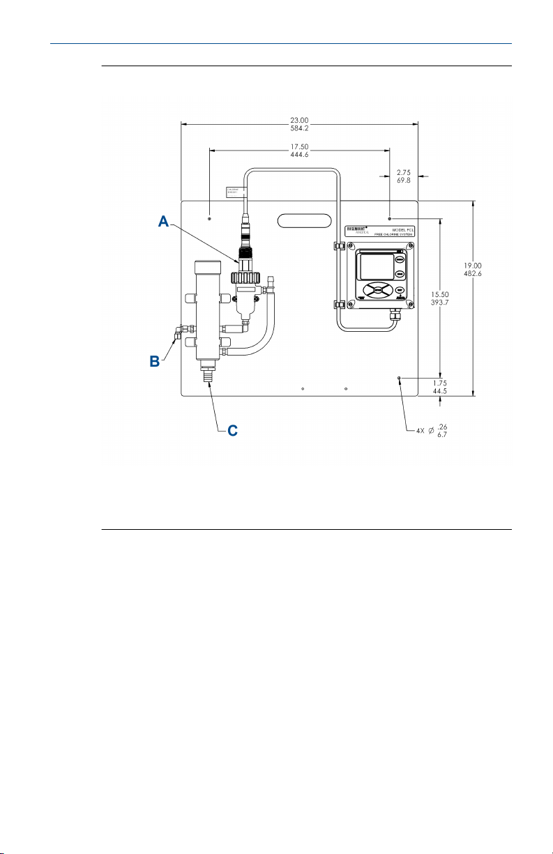
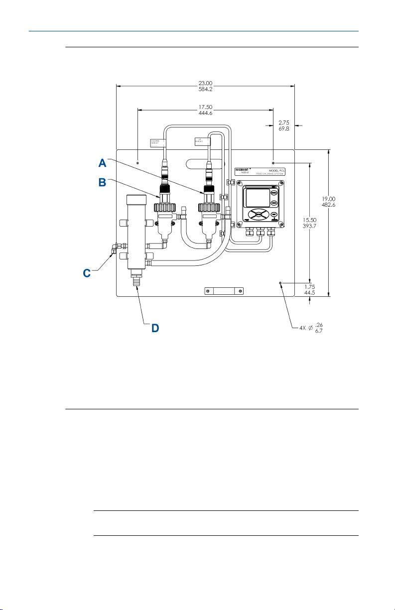
Refer to Figure 2-1 or Figure 2-2 for details. The sensor(s) screw into the flow
cell adapters as shown in the figures. For Rosemount FCL-02 (free chlorine
with continuous pH adjustment), you must also install the pH sensor.
8 Emerson.com/Rosemount
Page 9
January 2020 Quick Start Guide
Figure 2-1: Rosemount FCL-01
A. Chlorine sensor
B. Inlet
C. Drain
Quick Start Guide 9
Page 10
Quick Start Guide January 2020
Figure 2-2: Rosemount FCL-02
A. pH sensor
B. Chlorine sensor
C. Inlet
D. Drain
A ¼-in. OD tubing compression fitting is provided for the sample inlet. If
desired, you can remove the compression fitting and replace it with a barbed
fitting. The fitting screws into a ¼-in. FNPT check valve. The check valve
prevents the sensor flow cell from going dry if sample flow is lost.
The sample drains through a ¾-in. barbed fitting.
1. Attach a piece of soft tubing to the fitting and allow the waste to
drain to open atmosphere.
Important
Do not restrict the drain line.
10 Emerson.com/Rosemount
Page 11

January 2020 Quick Start Guide
2. Adjust the sample flow until the water level is even with the central
overflow tube and excess water is flowing down the tube.
3. Confirm that sample is flowing through the flow cells.
2.5 Install the sensor(s)
Emerson provides the Rosemount™ FCL with the sensor cable pre-wired to
the transmitter.
Procedure
1. Connect the chlorine sensor (Rosemount 499ACL-01-54-VP) to the
cable labeled CL.
2. Connect the pH sensor (Rosemount 3900-VP-02-10) to the cable
labeled pH.
The terminal end of the sensor is keyed to ensure proper mating with
the cable receptacle.
3. Once the key has slid into the mating slot, tighten the connection by
turning the knurled ring clockwise.
4. Screw the sensor(s) into the plastic fitting(s), which are held in the
flow cell(s) by the union nut.
Do not remove the protective cap on the sensor(s) until ready to put
the sensor(s) in service.
Quick Start Guide 11
Page 12

Quick Start Guide January 2020
3 Wire
3.1 Wire power
Wire AC mains power supply to the power supply board, which is mounted
on the left hand side of the transmitter enclosure beneath the gray plastic
cover.
WARNING
Electrical shock
Electrical installation must be in accordance with the National Electrical
Code (ANSI/NFPA-70) and/or any other applicable national or local codes.
Procedure
1. Unplug the connector from the board and wire the power cable to it.
Lead connections are marked on the connector. (L is live or hot; N is
neutral; the ground connection has the standard symbol.)
2. Provide a switch or breaker to disconnect the transmitter from the
main power supply.
3. Install the switch or breaker near the transmitter and label it as the
disconnecting device for the transmitter.
3.2
12 Emerson.com/Rosemount
Wire analog outputs
Four analog current outputs are located on the main circuit board, which is
attached to the inside of the enclosure door.
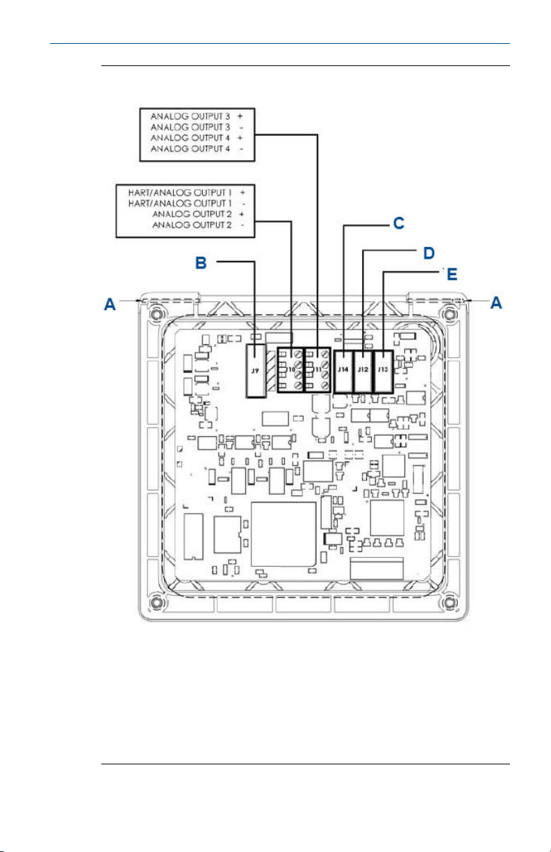
Figure 3-1 shows the locations of the terminals.
Page 13
January 2020 Quick Start Guide
Figure 3-1: Analog Output Connections
A. Hinge pin
B. To power supply PCB (ribbon cable)
C. To digital I/O communication board
D. To sensor 1 signal board
E. To sensor 2 signal board
The analog outputs are on the main board near the hinged end of the
enclosure door.
Quick Start Guide 13
Page 14

Quick Start Guide January 2020
For best EMI/RFI protection, use shielded output signal cable enclosed in
earth-grounded metal conduit.
Keep output signal wiring separate from power wiring. Do not run signal and
power or relay wiring in the same conduit or close together in a cable tray.
14 Emerson.com/Rosemount
Page 15
January 2020 Quick Start Guide
3.3 Wire alarm relays
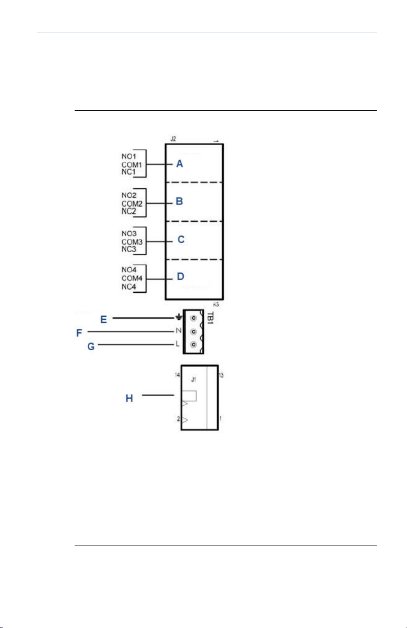
The alarm relay terminal strip is located on the power supply board, which is
mounted on the left hand side of the enclosure beneath the gray plastic
cover.
Figure 3-2: Alarm Relay Connections
A. Alarm relay 1
B. Alarm relay 2
C. Alarm relay 3
D. Alarm relay 4
E. Earth ground
F. Neutral
G. Line power
H. To main board (ribbon cable)
Quick Start Guide 15
Page 16

Quick Start Guide January 2020
Procedure
1. To remove the cover, grab it by the upper edges and pull straight
out.
The relay strip is at the top of the terminal board. See Figure 3-2.
2. Bring the relay wires through the rear conduit opening on the left
hand side of the enclosure and make connections to the terminal
strip.
3. Replace the cover.
The two tabs on the back edge of the cover fit into slots at the rear of
the enclosure, and the three small slots on the front of the cover snap
into the three tabs next to the relay terminal strip. See Figure 3-2.
Keep alarm wiring separate from signal wiring. Do not run signal and
power or relay wiring in the same conduit or close together in a tray.
3.4 Wire sensor
The Rosemount™ FCL is provided with sensor cables pre-wired to the
transmitter. If it is necessary to replace the sensor cable, refer to the
instructions below.
Procedure
1. Shut off power to the transmitter.
2. Loosen the four screws holding the front panel in place and let it drop
down.
3. Locate the appropriate signal board.
Slot 1 (left)
communication input 1 (chlorine) input 2 (optional)
Slot 2 (center) Slot 3 (right)
4. Loosen the gland fitting and carefully push the sensor cable up
through the fitting as you pull the board forward to gain access to the
wires and terminal screws.
5. Once the cable has been connected to the board, slide the board fully
into the enclosure while taking up the excess cable through the cable
gland.
6. Tighten the gland nut to secure the cable and ensure a sealed
enclosure.
16 Emerson.com/Rosemount
Page 17

January 2020 Quick Start Guide
3.5 Quick Start
Procedure
1. Once connections are secured and verified, apply power to the
transmitter.
When the transmitter is powered up for the first time, Quick Start
screens appear.
a. The cursor, shown by dark blue backlighting, is on the
language control box. To change the language, press the
ENTER/MENU key. A list of available languages, shown two at
a time, appears. Using the Up and Down keys, scroll (see ) to
display the choices. Press ENTER/MENU to select the desired
language. Press Down to move the cursor to the temperature
control box. To change units, press ENTER/MENU and scroll
to either °F or °C. Press ENTER/MENU to store the selection.
b. To move to the next screen, use the navigation keys to move
the cursor to NEXT and press ENTER/MENU.
2. The next screen lists navigation rules. Press ENTER/MENU for the
next screen.
3. Configure sensor 1.
Sensor 1 is the free chlorine sensor. The screen has three control
boxes.
a) For measurement, choose Free chlorine.
Important
Do not choose pH-independent free chlorine.
b) Choose the desired units, mg/L or ppm.
c) If you have a Rosemount™ FCL-02 (with pH sensor), the third
control box lets you choose between live/continuous or
manual pH correction.
If you choose live/continous (recommended), the transmitter
will use the pH measured by the pH sensor to correct the
chlorine reading for pH changes. If you choose manual (not
recommended), a fourth control box appears to let you enter
the manual pH, and the transmitter will use the entered value
to correct the chlorine reading.
d) If you have a Rosemount FCL-01 (no pH sensor), enter the pH
of the process liquid in the third control box.
e) Move the cursor to NEXT and press ENTER/MENU. If you have
a Rosemount FCL-01, the display changes to show some basic
Quick Start Guide 17
Page 18

Quick Start Guide January 2020
keypad operation guidelines. Press ENTER/MENU to show the
main display. If you have a Rosemount, go to the next step.
4. Configure sensor 2.
Sensor 2 is the pH sensor. The screen has two control boxes.
a) For measurement, choose pH.
b) For pre-amplifier location, choose analyzer.
c) Move the cursor to NEXT and press ENTER/MENU. The display
changes to show some basic keypad operation guidelines.
Press ENTER/MENU to show the main display.
The outputs, alarms, display configuration, and data logging are all assigned
to default values. The default value for data logging is disabled.
18 Emerson.com/Rosemount
Page 19
January 2020 Quick Start Guide
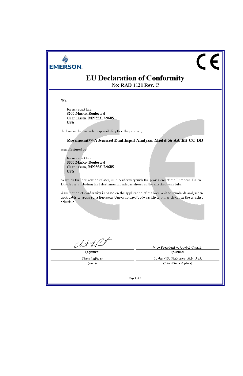
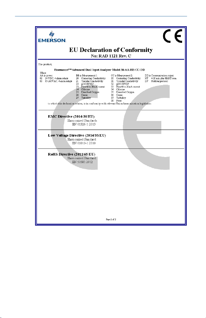
A EU Declaration of Conformity
Quick Start Guide 19
Page 20
Quick Start Guide January 2020
20 Emerson.com/Rosemount
Page 21
January 2020 Quick Start Guide
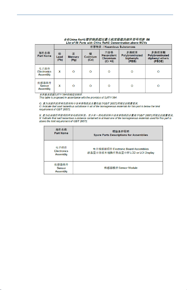
B China RoHS table
Quick Start Guide 21
Page 22

Quick Start Guide January 2020
22 Emerson.com/Rosemount
Page 23

January 2020 Quick Start Guide
Quick Start Guide 23
Page 24

GLOBAL HEADQUARTERS
6021 Innovation Blvd.
Shakopee, MN 55379
+1 866 347 3427
+1 952 949 7001
[email protected]
*00825-0200-3412*
Quick Start Guide
00825-0200-3412, Rev. AA
January 2020
NORTH AMERICA
Emerson Automation Solutions
8200 Market Blvd
Chanhassen, MN 55317
Toll Free +1 800 999 9307
F +1 952 949 7001
[email protected]
MIDDLE EAST AND AFRICA
Emerson Automation Solutions
Emerson FZE
Jebel Ali Free Zone
Dubai, United Arab Emirates, P.O. Box
17033
+971 4 811 8100
+971 4 886 5465
[email protected]
LinkedIn.com/company/Emerson-
Automation-Solutions
Twitter.com/rosemount_news
Facebook.com/Rosemount
Youtube.com/RosemountMeasurement
EUROPE
Emerson Automation Solutions
Neuhofstrasse 19a PO Box 1046
CH-6340 Baar
Switzerland
+41 (0) 41 768 6111
+41 (0) 41 768 6300
[email protected]
ASIA-PACIFIC
Emerson Automation Solutions
1 Pandan Crescent
Singapore 128461
Republic of Singapore
+65 6 777 8211
+65 6 777 0947
[email protected]
©
2020 Emerson. All rights reserved.
The Emerson logo is a trademark and service
mark of Emerson Electric Co. Rosemount is a
mark of one of the Emerson family of companies.
All other marks are the property of their
respective owners.
 Loading...