


Manual Supplement
00809-0700-4570, Rev AA
May 2016
Rosemount™ 5708 3D Solids Scanner
Integration with Ovation
Introduction . . . . . . . . . . . . . . . . . . . . . . . . . . . . . . . . . . . . . . . . . . . . . . . . . . . . . . . . . . . . . .page 1
Specifications . . . . . . . . . . . . . . . . . . . . . . . . . . . . . . . . . . . . . . . . . . . . . . . . . . . . . . . . . . . . . page 2
Hardware overview . . . . . . . . . . . . . . . . . . . . . . . . . . . . . . . . . . . . . . . . . . . . . . . . . . . . . . . . page 2
Wiring setup . . . . . . . . . . . . . . . . . . . . . . . . . . . . . . . . . . . . . . . . . . . . . . . . . . . . . . . . . . . . . . page 2
Network setup . . . . . . . . . . . . . . . . . . . . . . . . . . . . . . . . . . . . . . . . . . . . . . . . . . . . . . . . . . . . page 3
Configuring RS485 - to -TCP/IP converter . . . . . . . . . . . . . . . . . . . . . . . . . . . . . . . . . . . . . page 4
Configuring Rosemount 3DMultiVision software . . . . . . . . . . . . . . . . . . . . . . . . . . . . . . page 5
Configuring Rosemount 3DMultiVision software to be Modbus Master . . . . . . . . . . . page 8
Viewing the 3D image viewer from a graphic . . . . . . . . . . . . . . . . . . . . . . . . . . . . . . . . . .page 9
1.1 Introduction
This document indicates how to setup and configure Rosemount 5708 3D Solids Scanner with
Ovation using the Ethernet Link Controller (ELC) module. Configuration details are included for
the physical network, Ovation Developer Studio, ELC protocol configuration tool, and
Rosemount 3DMultiVision
discussed in this document; however the principle is the same. Refer to the Redundant Modbus
Interface User Guide for Ovation Windows Platform, CON_020, for more information.
™
Client. Ethernet data links not utilizing the ELC module is not
™
®
The ELC protocol configuration tool interfaces with the ELC module - a necessary component for
one of the setups which Ovation communicates with the Rosemount 3DMultiVision server
through. This software typically resides on the database server. Ovation configuration is
performed on the database server or any machine that has access to the Ovation Developer
Studio; Rosemount 3DMultiVision configuration is performed on an application station.
After the configuration is complete, Ovation and Rosemount 3DMultiVision Server/Client will be
able to run in parallel when using an ELC module. The level variables will be able to be accessed
by the controller for indication and used on control sheets/graphics in Ovation. The application
station will be able to use the Rosemount 3DMultiVision software to setup the Rosemount 3D
Solids Scanner, show detail curves, and monitor values.

Rosemount 5708 Integration with Ovation
May 2016
1.2 Specifications
The configuration presented here has been verified with the following specifications:
Ovation version 3.5.1
Ethernet Link Controller version 1.3
Rosemount 3DMultiVision version 2.3.020
The device can also be directly connected to an ELC or RLC module via 2-wire RS485 serial
connection. However, a serial connection prevents the Rosemount 3DMultiVision software
from being used in parallel.
1.3 Hardware overview
Figure 1-1 depicts a basic layout utilizing one Rosemount 3D Solids Scanner. The
RS485-to-TCP/IP converter, Rosemount 3DMultiVision Server, Database Server, and the ELC
module should all be connected to a switch. For simplicity sake, this example will connect all
of the Ethernet connections to one root switch; including the Ovation controllers. Based on
security or redundancy requirements, your configuration may differ.
Manual Supplement
00809-0700-4570, Rev AA
Although the Rosemount 3D Solids Scanner has a 2-wire RS485 serial connection, due to
the RS485-to-TCP/IP converter, Ovation will treat the communication as a Modbus Ethernet
link. On top of receiving the Rosemount 3D Solids Scanner data, the Rosemount
3DMultiVision Server will act as a Modbus Master. It will poll the Rosemount 3D Solids
Scanner and allow Modbus Slave Connections to read the Modbus registers from the
Rosemount 3DMultiVision Server. The ELC module in this configuration will act as a Modbus
Slave and will connect to the Rosemount 3DMultiVision Server's IP address, not the
RS485-to-TCP/IP’s IP address.
1.4 Wiring setup
Note
An external power supply is required to power the Rosemount 5708 3D Solids Scanner.
1. Connect the power to the terminations on the scanner labeled “PWR IN”.
A hard wired 4-20mA signal can be sent to an Ovation analog input module.
Specific details on how to assign and configure the hardwired point is not covered
in this document, however it should be mentioned that the point should be wired
for a FIELD powered device. This typically means moving the jumpers on the
Ovation analog input personality module.
The Rosemount 3D Solids Scanner has a 2-wire RS485 connection. Multiple
Rosemount 5708 may be connected together in parallel and still have one RS485
connection. The 3D Scanner Reference Manual provide specific information as to
how this is accomplished. As stated above, a RS485-to-TCP/IP converter is required
to use the points in Ovation and the Rosemount 3DMultiVision software in parallel.
2
Rosemount 5708 Integration with Ovation

Manual Supplement
RS-485
Ethernet
A
B
C
DE
F
00809-0700-4570, Rev AA
2. Connect the positive terminal on the scanner to the positive terminal on the
converter; and the negative terminal on the scanner to the negative terminal on the
converter.
Note
You must use a 120 Ω resistor at each end of the connection or the Modbus communication
will have errors.
1.5 Network setup
To be able to run Rosemount 3DMultiVision software simultaneously with Ovation, set up a
network switch connected to the Ovation controllers, the Ovation Database Server, the
Ovation Operator Station, and the ELC module. The Ovation Operator Station will be the
station running the Rosemount 3DMultiVision software.
Note
The Rosemount 3D Solids Scanner uses a serial communication link to the network. An
RS485 to TCP/IP converter is required to connect the device to the network switch. Again
depending on security requirements, a field LAN router may be needed in between the
converter and the root switch.
Rosemount 5708 Integration with Ovation
May 2016
In this example, we will assume the equipment is all in the 172.28.2.xxx range with the
subnet of 255.255.255.0.
Figure 1-1. Network Diagram
Rosemount 5708 Integration with Ovation
A. Ethernet switch
B. Ovation controllers
C. Ethernet link module
D. 120 Ω resistor
E. DB server
F. Operator station (running 3D Vision SW)
3

Rosemount 5708 Integration with Ovation
May 2016
Manual Supplement
00809-0700-4570, Rev AA
1.6 Configuring RS485 - to -TCP/IP converter
Note
Rosemount 5708 is recommending the CHIYU BF-430 as the RS485 to TCP/IP converter.
Other converters are compatible, but have not been tested.
1. Assign a static IP address, subnet, gateway, and port number for this connection.
Below is an example configuration.
Note
The IP address and port number. It will be needed when configuring the 3DMultiVision
Server.
2. Match the physical layer in the converter to the Rosemount 3D Solids Scanner.
Baud Rate = 115200
Data Bits = 8
Parity = None
Stop Bits = 1
4
Rosemount 5708 Integration with Ovation

Manual Supplement
00809-0700-4570, Rev AA
Rosemount 5708 Integration with Ovation
1.7 Configuring Rosemount 3DMultiVision software
Note
Consult the Commissioning section in the Rosemount 5708 Reference Manual
detailed information.
1. Install the Rosemount 3DMultiVision Server software that came with the
Rosemount 3D Solids Scanner.
If needed, you can install the Client software on other machines provided they are
on the same network.
2. Start the Rosemount 3DVision Server.
a. Double click the Rosemount 3DVision Server desktop icon to start the server
application.
May 2016
for more
b. The server application may need some time to initialize communications with
the scanners and clients. Ensure the server icon appears on the task bar as
shown.
The server should remain running. Manually running the server is required only if
the computer is restarted and the server does not start automatically.
When installing the server, it is added to the Windows Start Up files automatically.
3. Double click the Rosemount 3DVision Client icon to start the client application.
Rosemount 5708 Integration with Ovation
5

Rosemount 5708 Integration with Ovation
May 2016
The application opens and the Server Connection dialog box appears.
Manual Supplement
00809-0700-4570, Rev AA
4. On the first connection attempt, the Server Name and Server Address fields are
empty and the relevant details must be entered. The connection information is
kept for subsequent connections.
5. In the Server Name field, enter your own description for the system managed by that
server.
a. To activate the Server Name field, select Edit... then the Server Configuration
window appears.
b. In the Server Address field, enter the IP address of the computer running the
Rosemount 3DVision Server:
If both client and server applications are installed and running on the same
computer, enter the computer local IP address, or type IP 127.0.0.1 or type
localhost.
If the client application is running on a remote computer, enter the IP
address of the computer running the Rosemount 3DVision Server
application.
c. In the Server Port field, verify the server port is set to 22222.
6
Rosemount 5708 Integration with Ovation

Manual Supplement
00809-0700-4570, Rev AA
6. Select Stay Signed In to automatically sign in on the next execution of the
7. Select Slow Connection to increase timers and timeouts of various commands in
8. Select the Auto Reconnection after option to allow the Rosemount 3DVision
Rosemount 5708 Integration with Ovation
May 2016
Rosemount 3DVision Client application.
case of slow communication between the Rosemount 3DVision Server and the
scanners.
Client to automatically reconnect (with a delay of 20 seconds) to the Rosemount
3DVision Server.
9. Select Connect. The application connects and the Login dialog box appears.
10. Enter User Name and Password. The default username and password are both admin
(case sensitive).
Note
It is possible to sign out from the File menu under: File > Exit.
11. Select Connect after entering in the appropriate information. If this is connected
successfully, the Rosemount 3DMultiVision window should appear.
12. If necessary, create a new project and setup the device.
a. Specify the name of the project, number of sites, and select Next.
b. Set the Connection Type to TCP/IP.
c. Set the Server IP Address to the IP address of the RS485 to TCP/IP converter
connected to the Rosemount 3D Solids Scanner device (e.g. 172.28.2.90).
d. Set the Server IP Port to the port of the RS485 to TCP/IP converter (e.g. 50000).
Make sure the polling address in the scanner matched the polling address you are
connecting to.
You should now be able to connect to the Rosemount 3D Solids Scanner from the
Rosemount 3DMultiVision Client.
Consult the Reference Manual for instructions to set up the vessel(s) at your site.
Rosemount 5708 Integration with Ovation
7

Rosemount 5708 Integration with Ovation
May 2016
Manual Supplement
00809-0700-4570, Rev AA
1.8 Configuring Rosemount 3DMultiVision software to be Modbus Master
Supports Modbus RTU and Modbus TCP.
Not include 3D Picture option.
To conf igure SC ADA ports:
1. Inside the Rosemount 3DMultiVision Program go to Tools > Server Options… > Scada
Configuration.
2. Select the Scada Configuration option.
a. Select a Port Number (e.g. 7040).
Note
This port will be same for the Ovation ELC configuration.
b. Select Modbus RTU. The ELC Module does not communicate with the
Rosemount 3DMultiVision server via Modbus TCP.
c. 3D Image File Path: This path will hold the 3D Image file which the
VisualVision3DViewer will read from there (You can leave it empty, so it will use
the local default path). It's required to set a different path for each port. If the
directory (folder) does not exist, you will need to create it. In this example, we
will use C:\DirectoryFor3DImage, however you may need to set the path to be
on a mapped (Z:\) drive so that it may be accessed by all operators. When the
ELC module sends a request for register 49990, the Rosemount 3DMultiVision
server receives that request and generates a .enc file.
d. Confirm by selecting Apply button.
8
Rosemount 5708 Integration with Ovation

Manual Supplement
00809-0700-4570, Rev AA
Rosemount 5708 Integration with Ovation
May 2016
1.9 Viewing the 3D image viewer from a graphic
To display the viewer manually:
1. Open Command Line.
2. Write this command (according to the specific port you want to view):
The 3D Image File Path From Rosemount 3DVision Scada Configuration = The
3D Image File Path from the SCADA configuration screen in the Rosemount
3DVision.
If the path is empty, remove the The 3D Image File Path From Rosemount
3DVision Scada Configuration expression from the command.
ID_Num = Vessel Index (ID number from the device configuration)
(Win 7 - 64Bit)
“C:\Program Files (x86)\3DVisionEmrsn\binClient\bin\VisualVision3DViewer.exe” “The 3D
Image File Path From 3DVision Scada Configuration” ID_Num;
(Win XP)
“C:\Program Files\3DVisionEmrsn\binClient\bin\VisualVision3DViewer.exe” “The 3D Image
File Path From 3DVision Scada Configuration” ID_Num;
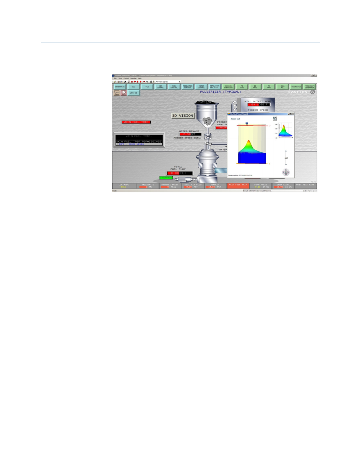
To display the viewer from an Ovation graphic:
A button or poke field can be configured in a graphic that will display the 3D image of the
vessel, however Ovation command line calls do not support parameters after the exe file. To
get around this a batch (.bat) file can be created.
1. Create a batch file.
a. Open Notepad and enter:
Start “” “C:\Program Files
(x86)\3DVisionEmrsn\binClient\bin\VisualVision3DViewer.exe”
C:\DirectoryFor3DImage 1
Exit
where C:\DirectoryFor3DImage = the path specified in the Rosemount
3DMultiVision Server Scada configuration and 1 = the vessel number.
b. Save the file as a .bat in C:\DirectoryFor3DImage (or the directory of your
choice). Example: 3dimage.bat
Note
This is the file the Ovation graphic will open.
2. Open the graphic in the graphic editor where you would like to create a button.
a. Select on the button icon to create a new button. This will bring up the button
configuration GUI.
Rosemount 5708 Integration with Ovation
9

Rosemount 5708 Integration with Ovation
May 2016
b. Configure the size, text, color in the appearance tab:
Manual Supplement
00809-0700-4570, Rev AA
c. Select the function tab,
i. Set Functionality to Poke.
ii. Set Poke Type to Application (9).
iii. In the Cmd Line, enter the path and file name of the batch file you created in
step 2.
10
d. Select Apply.
e. Position the button and select Save.
Rosemount 5708 Integration with Ovation
Manual Supplement
00809-0700-4570, Rev AA
3. Download the graphic in Ovation Developer Studio.
4. Test by opening the graphic and selecting the button.
Rosemount 5708 Integration with Ovation
May 2016
If an image does not display, verify the .enc file is being created and stored at the specified
location (e.g. C:\DirectoryFor3DImage).
Rosemount 5708 Integration with Ovation
11

Global Headquarters
Emerson Process Management
6021 Innovation Blvd.
Shakopee, MN 55379, USA
+1 800 999 9307 or +1 952 906 8888
+1 952 949 7001
RFQ.RMD-RCC@EmersonProcess.com
North America Regional Office
Emerson Process Management
8200 Market Blvd.
Chanhassen, MN 55317, USA
+1 800 999 9307 or +1 952 906 8888
+1 952 949 7001
RMT-NA.RCCRFQ@Emerson.com
Latin America Regional Office
Emerson Process Management
1300 Concord Terrace, Suite 400
Sunrise, FL 33323, USA
+1 954 846 5030
+1 954 846 5121
RFQ.RMD-RCC@EmersonProcess.com
Manual Supplement
00809-0700-4570, Rev AA
May 2016
Europe Regional Office
Emerson Process Management Europe GmbH
Neuhofstrasse 19a P.O. Box 1046
CH 6340 Baar
Switzerland
+41 (0) 41 768 6111
+41 (0) 41 768 6300
RFQ.RMD-RCC@EmersonProcess.com
Asia Pacific Regional Office
Emerson Process Management Asia Pacific Pte Ltd
1 Pandan Crescent
Singapore 128461
+65 6777 8211
+65 6777 0947
Enquiries@AP.EmersonProcess.com
Middle East and Africa Regional Office
Emerson Process Management
Emerson FZE P.O. Box 17033
Jebel Ali Free Zone - South 2
Dubai, United Arab Emirates
+971 4 8118100
+971 4 8865465
RFQ.RMTMEA@Emerson.com
Linkedin.com/company/Emerson-Process-Management
Twitter.com/Rosemount_News
Facebook.com/Rosemount
Youtube.com/user/RosemountMeasurement
Google.com/+RosemountMeasurement
Standard Terms and Conditions of Sale can be found at:
Emerson.com/en-us/pages/Terms-of-Use.aspx
The Emerson logo is a trademark and service mark of Emerson Electric Co.
Modbus is a registered trademark of Modicon, Inc.
Ovation, 3DMultiVision, Rosemount, and Rosemount logotype are trademarks
of Emerson Process Management.
All other marks are the property of their respective owners.
© 2016 Emerson Process Management. All rights reserved.
 Loading...