

Page 1
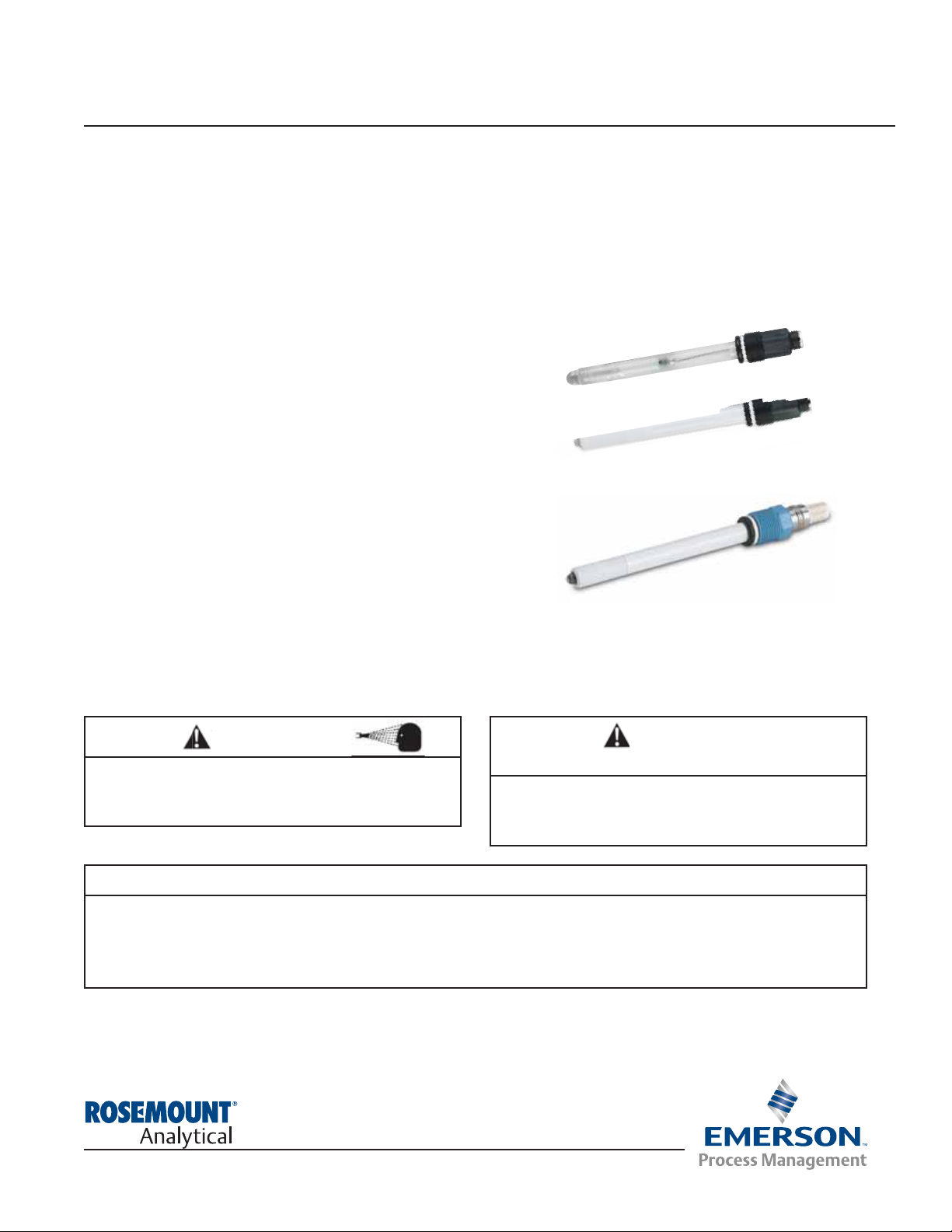
EuroSenzTMModel 371 pH/ORP Sensor and Model 370 pH Sensor
Low Maintenance pH Combination
Electrode
Instruction Sheet
PN 51A-371pH/rev.D
January 2011
SPECIFICATIONS
pH Range: 0-14 pH
ORP Range: ± 1500 mV
Glass Type: General Purpose Low Resistance (GPLR)
Percent Linearity: 96% @ 0-4 pH, 99% @ 4-12 pH,
97% @ 12-13 pH, 92% @ 13-14 pH
Temperature Range: 0° - 85°C (32° - 185°F)
Pressure Range: 100-790 kPa abs (0-100 psig)
Conductivity: >100mS/cm
Wetted Materials: Polypropylene, EP, and Glass
Process Connection: Standard PG 13.5 Thread
Cable Connection: Eurocab (-70); VP (-72)
S8 Cable: Single Pole Euro PN:9200338
VP8 Cable: PN: 24281-00
For additional information please visit our website at
www.emersonprocess.com/raihome/liquid/.
371-72 (VP sensor)
370 and 371-70 Eurocap
WARNING
Before removing the sensor, be absolutely certain
that the process pressure is reduced to 0 psig and
the process temperature is lowered to a safe level!
WARNING
The wetted sensor materials may not be compatible
with process com position and operating conditions.
Application compat ibility is entirely the
responsi-
bility of the user.
CAUTION
SENSOR/PROCESS APPLICATION COMPATIBILITY
ATEX DIRECTIVE
Special Conditions for safe use
1. All pH/ORP sensors have a plastic enclosure which must only be cleaned with a damp cloth to avoid the
danger due to a build up of an electrostatic charge.
2. All pH/ORP sensor Models are intended to be in contact with the process fluid and may not meet the 500V
r.m.s. a.c. test to earth. This must be taken into consideration at installation.
Page 2
2
STORAGE
1. It is recommended that electrodes be stored in their original shipping containers until needed.
2. Do not store at temperatures below -5°C (23°F).
3. Electrodes should be stored with a protective cap containing KCl solution (PN 9210342).
4. For overnight storage, immerse the sensor in tap water or 4 pH buffer solution.
5. A pH glass electrode has a limited shelf life of one year.
ELECTRODE PREPARATION
1. Remove electrode from shipping container.
2. Remove the protective boot covering the electrode bulb.
3. Rinse away salt film with clean water, then shake the electrode so that the internal solution fills the bulb, thus
removing any air trapped there.
NOTE
Do not allow lubricant to coat electrode bulb or reference junction. If it does, wipe it clean before installation.
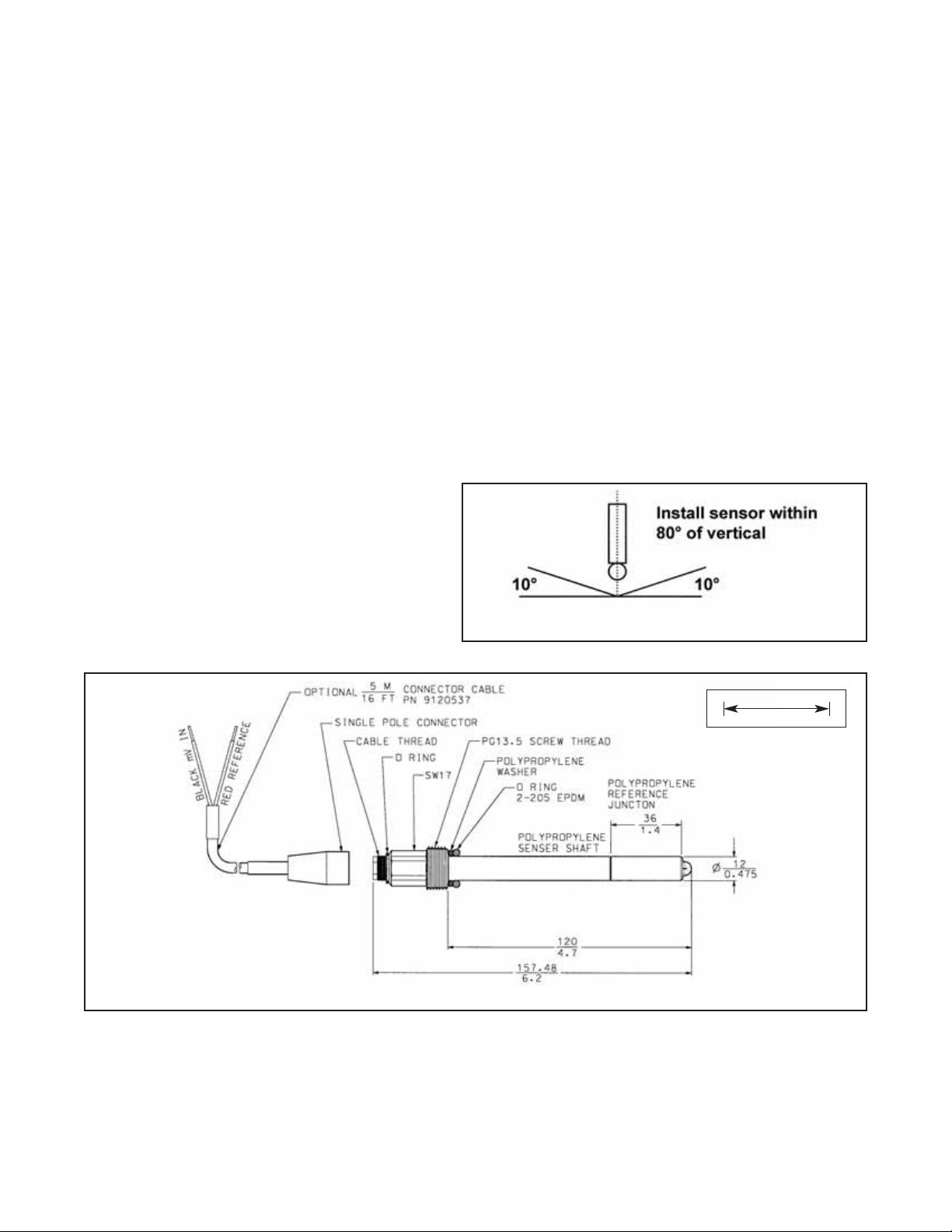
INSTALLATION
For sensor orientation, see Figure 1.
For wiring, see Figures 3 and 4.
FIGURE 1. Sensor Orientation
FIGURE 2. Sensor Dimensions
MILLIMETER
INCH
Page 3

3
RECOMMENDED pH SENSOR
STANDARDIZATION
For maximum accuracy, the sensor can be standardized on-line or with a process grab sample after a
buffer calibration has been performed and the sensor
has been conditioned to the process. Standardization
accounts for the sensor junction potential and other
interferences. Standardization will not change the sensor’s slope but will simply adjust the analyzer’s reading
to match that of the known process pH.
MAINTENANCE
Electrodes should respond rapidly. Sluggishness, offsets, and erratic readings are indicators that the electrodes may need cleaning or replacement.
1. To remove oil deposit, clean the electrode with a
mild non-abrasive detergent.
2. To remove scale deposits, soak electrodes for 30 to
60 minutes in a 5% hydrochloric acid solution.
3. Temperature effect on life expectancy: If glass electrode life expectancy is 100% @ 25°C (77°F), then
it will be approximately 25% @ 80°C (176°F), and
approximately 5% @ 120°C (248°F).
TWO POINT BUFFER CALIBRATION
Select two stable buffer solutions, preferably pH 4.0 and 10.0 (pH buffers other than pH 4.0 and pH 10.0 can be
used as long as the pH values are at least two pH units apart).
NOTE
A pH 7 buffer solution reads a mV value of approx. zero, and pH buffers read approximately ± 59.1
mV for each pH unit above or below pH 7. Check the pH buffer manufacturer specifications for millivolt values at various temperatures since it may affect the actual value of the buffer solution
mV/pH value.
1. Immerse sensor in the first buffer solution. Allow sensor to equilibrate to the buffer temperature (to avoid errors
due to temperature differences between the buffer solution and sensor temperature) and wait for reading to
stabilize. Value of buffer can now be acknowledged by analyzer/transmitter.
2. Once the first buffer has been acknowledged by the analyzer/transmitter, rinse the buffer solution off of the
sensor with distilled or deionized water.
3. Repeat steps 1 and 2 using the second buffer solution.
4. The theoretical slope value, according to the Nernst equation for calculating pH, is approximately 59.17 mV/pH.
Over time the sensor will age, both in the process and in storage, and will result in reduced slope values. To
ensure accurate readings, it is recommended that the electrode be replaced when the slope value falls below
47 to 49 mV/pH.
Page 4

FIGURE 5. VP8 Wiring to 1056 analyzer
FIGURE 6. VP8 Cable Wiring to 5081 analyzer
WIRING
FIGURE 3. VP8 Cable, instrument end
for Model 371 option (-72)
FIGURE 4. VP8 Cable, sensor end for
Model 371 option (-72)
4
371-72
371-72
VP8 Cable P/N 24281-XX
Page 5

5
FIGURE 7. VP8 Wiring to 54e analyzer
FIGURE 8. VP8 Cable Wiring to 6081 wireless transmitter
371-72
Page 6

FIGURE 9. VP8 Wiring to Xmt analyzer. Model 371-72
FIGURE 10. 371-72 wiring to Model 1055-01-10-22 single sensor wiring VP6 (28645-XX)
FIGURE 11. 371-72 Wiring to Model 1055-01-10-22-32 dual sensor wiring VP6 (28645-XX)
6
371-72
Page 7

7
FIGURE 12. S8 Cable Wiring to Models 1181, 1054A/B, 2081, 54, 81, 3081, 4081 and 5081.
Models 370 and 371-70
MODEL
54e
81
3081, 4081,
5081-P
FIGURE 13. S8 Cable Wiring to Model 1055-10-22-32. Models 370 and 371-70
Page 8

Credit Cards for U.S. Purchases Only.
The right people,
the right answers,
right now.
ON-LINE ORDERING NOW AVAILABLE ON OUR WEB SITE
http://www.raihome.com
Specifications subject to change without notice.
Emerson Process Management
2400 Barranca Parkway
Irvine, CA 92606 USA
Tel: (949) 757-8500
Fax: (949) 474-7250
http://www.raihome.com
© Rosemount Analytical Inc. 2011
PN
DESCRIPTION
9200338 Cable with single pole connector for Eurocap (option -70 and Model 370), coaxial connection, 5 m (16.4 ft)
9200339 Cable with single pole connector for Eurocap (option -70 and Model 370), coaxial connection, 10 m (33 ft)
9120550 Cable with VP 6.0 connector (option -72), coaxial connection with TC (option -72), 3 m (9.8 ft)
9160504 Cable with VP 6.0 connector (option -72), coaxial connection with TC (option -72), 5 m (16.4 ft)
9210012 Buffer solution, 4.01 pH, 500 ml (16 oz)
9210013 Buffer solution, 6.86 pH, 500 ml (16 oz)
9210014 Buffer solution, 9.18 pH, 500 ml (16 oz)
9120342 KCl electrolyte solution, 250 ml (8 oz)
R508-802 ORP standard solution, 460 mV, 500 ml (8 oz)
24281-00 15 ft. cable with mating VP8 connector
24281-01 25 ft. cable with mating VP8 connector
24281-02 2.5 ft. cable with mating VP8 connector
24281-03 50 ft. cable with mating VP8 connector
24281-04 100 ft. cable with mating VP8 connector
24281-05 4 ft. cable with mating VP8 connector
24281-06 10 ft. cable with mating VP8 connector
24281-07 20 ft. cable with mating VP8 connector
24281-08 30 ft. cable with mating VP8 connector
ACCESSORIES
PN
DESCRIPTION
9200338 Cable with single pole connector for Eurocap (option -70 and Model 370), coaxial connection, 5 m (16.4 ft)
9200339 Cable with single pole connector for Eurocap (option -70 and Model 370), coaxial connection, 10 m (33 ft)
9120550 Cable with VP 6.0 connector (option -72), coaxial connection with TC (option -72), 3 m (9.8 ft)
9160504 Cable with VP 6.0 connector (option -72), coaxial connection with TC (option -72), 5 m (16.4 ft)
9210012 Buffer solution, 4.01 pH, 500 ml (16 oz)
9210013 Buffer solution, 6.86 pH, 500 ml (16 oz)
9210014 Buffer solution, 9.18 pH, 500 ml (16 oz)
9120342 KCl electrolyte solution, 250 ml (8 oz)
R508-802 ORP standard solution, 460 mV, 500 ml (8 oz)
24281-00 15 ft. cable with mating VP8 connector; 371 sensor option (-72)
24281-01 25 ft. cable with mating VP8 connector; 371 sensor option (-72)
24281-02 2.5 ft. cable with mating VP8 connector; 371 sensor option (-72)
24281-03 50 ft. cable with mating VP8 connector; 371 sensor option (-72)
24281-04 100 ft. cable with mating VP8 connector; 371 sensor option (-72)
24281-05 4 ft. cable with mating VP8 connector; 371 sensor option (-72)
24281-06 10 ft. cable with mating VP8 connector; 371 sensor option (-72)
24281-07 20 ft. cable with mating VP8 connector; 371 sensor option (-72)
24281-08 30 ft. cable with mating VP8 connector; 371 sensor option (-72)
8
 Loading...