

Page 1

00809-0100-4754
English
Rev. BB
Model 333 HART®
Tri-Loop™ HART-to-Analog
Signal Converter
Page 2

Page 3

Product Manual
Model 333 HART
®
Tri-Loop
™
HART-to-Analog
Signal Converter
HART Tri-Loop Software Revision 1
HART Tri-Loop Configurator Software Revision 1.02
NOTICE
Read this manual before working with the product. For personal and system
safety, and for optimum product performance, make sure you thoroughly
understand the contents before installing, using, or maintaining this product.
Within the United States, Rosemount Inc. has two toll-free assistance numbers.
Customer Central: 1-800-999-9307 (
Technical support, quoting, and order-related questions.
North American 1-800-654-7768 (
Response Center: Equipment service needs.
For equipment service or support needs outside the United States, contact your
local Rosemount representative.
7:00 a.m. to 7:00 p.m. CST)
24 hours a day – Includes Canada)
Rosemount Inc.
8200 Market Boulevard
Chanhassen, MN 55317 USA
Tel 1-800-999-9307
Fax (612) 949-7001
© 1996, 1999 Rosemount, Inc.
http://www.rosemount.com
The products described in this document are NOT designed for nuclearqualified applications.
Using non-nuclear qualified products in applications that require nuclearqualified hardware or products may cause inaccurate readings.
For information on Rosemount nuclear-qualified products, contact your local
Rosemount Sales Representative.
SNF-0004
Rosemount and the Rosemount logotype are registered trademarks of Rosemount Inc.
Tri-Loop, Multivariable, MV, and Hot Backup are trademarks of Rosemount Inc.
HART is a registered trademark of the HART Communication Foundation.
Microsoft and Windows are registered trademarks of Microsoft Corp.
Cover Photo: 3095-005AB
Fisher-Rosemount satisfies all obligations coming from legislation
to harmonize product requirements in the European Union.
T
N
I
E
D
R
P
IN
U.
A.
S.
Page 4

Page 5

Table of Contents
SECTION 1
Introduction
SECTION 2
Installation
Using This Manual . . . . . . . . . . . . . . . . . . . . . . . . . . . . . . . . . . . . 1-1
System overview . . . . . . . . . . . . . . . . . . . . . . . . . . . . . . . . . . . . . . 2-2
Unpacking The HART Tri-loop . . . . . . . . . . . . . . . . . . . . . . . . . . 2-2
Initial Inspection . . . . . . . . . . . . . . . . . . . . . . . . . . . . . . . . . . 2-3
Model 3095 MV (or HART Multivariable Device) . . . . . . . . 2-3
Alarms . . . . . . . . . . . . . . . . . . . . . . . . . . . . . . . . . . . . . . . . . . 2-3
Failure Mode Alarm vs. Saturation Output Values . . . . . . . 2-3
Installation Considerations . . . . . . . . . . . . . . . . . . . . . . . . . . . . . 2-4
Mechanical Considerations . . . . . . . . . . . . . . . . . . . . . . . . . . 2-4
Electrical Considerations . . . . . . . . . . . . . . . . . . . . . . . . . . . 2-5
Power Supply . . . . . . . . . . . . . . . . . . . . . . . . . . . . . . . . . . . . . 2-5
Installation Equipment . . . . . . . . . . . . . . . . . . . . . . . . . . . . . . . . 2-6
Installation Procedure . . . . . . . . . . . . . . . . . . . . . . . . . . . . . . . . . 2-6
1. Review Installation Considerations . . . . . . . . . . . . . . . . . 2-6
2.Mount Tri-Loop on DIN Rail . . . . . . . . . . . . . . . . . . . . . . . 2-6
3. Wiring . . . . . . . . . . . . . . . . . . . . . . . . . . . . . . . . . . . . . . . . . 2-6
Configure the Model 3095 MV For Tri-loop Operation . . . . 2-8
Select Process Variables . . . . . . . . . . . . . . . . . . . . . . . . . . . . 2-8
Record Model 3095 MV Units . . . . . . . . . . . . . . . . . . . . . . . . 2-9
Set the Model 3095 MV to Burst Mode . . . . . . . . . . . . . . . 2-10
SECTION 3
Commissioning
Overview . . . . . . . . . . . . . . . . . . . . . . . . . . . . . . . . . . . . . . . . . . . . 3-1
Install The Tri-loop Configurator Software . . . . . . . . . . . . . . . . 3-1
Minimum Equipment and Software . . . . . . . . . . . . . . . . . . . 3-2
Installation Procedure . . . . . . . . . . . . . . . . . . . . . . . . . . . . . . 3-2
Configure the Tri-loop . . . . . . . . . . . . . . . . . . . . . . . . . . . . . . . . . 3-3
Help Files . . . . . . . . . . . . . . . . . . . . . . . . . . . . . . . . . . . . . . . . 3-3
Connect the PC to the Tri-Loop . . . . . . . . . . . . . . . . . . . . . . 3-3
Configuration Procedure . . . . . . . . . . . . . . . . . . . . . . . . . . . . 3-4
Menu Structure . . . . . . . . . . . . . . . . . . . . . . . . . . . . . . . . . . . . . . 3-6
iii
Page 6

SECTION 4
Troubleshooting
SECTION 5
Specifications and
Reference Data
Appendix A
Appendix B
Ordering Information . . . . . . . . . . . . . . . . . . . . . . . . . . . . . . . . . . 5-1
Specifications . . . . . . . . . . . . . . . . . . . . . . . . . . . . . . . . . . . . . . . . 5-1
Functional
Specifications . . . . . . . . . . . . . . . . . . . . . . . . . . . . . . . . . . . . . 5-1
Performance Specifications . . . . . . . . . . . . . . . . . . . . . . . . . . 5-2
Physical Specifications . . . . . . . . . . . . . . . . . . . . . . . . . . . . . 5-2
Configuration Data Sheet 00806-0100-4754 . . . . . . . . . . . . . . . 5-3
Overview . . . . . . . . . . . . . . . . . . . . . . . . . . . . . . . . . . . . . . . . . . . . A-1
Installation . . . . . . . . . . . . . . . . . . . . . . . . . . . . . . . . . . . . . . . . . . A-1
Commissioning the Transmitter . . . . . . . . . . . . . . . . . . . . . . . . . A-2
Set the Transmitter to Burst Mode . . . . . . . . . . . . . . . . . . . A-2
Set Process Variable Output Order . . . . . . . . . . . . . . . . . . . A-2
Special Considerations . . . . . . . . . . . . . . . . . . . . . . . . . . . . . A-3
Introduction . . . . . . . . . . . . . . . . . . . . . . . . . . . . . . . . . . . . . . . . . B-1
Communicating with a HART Tri-Loop . . . . . . . . . . . . . . . . . . . B-1
Online Menu . . . . . . . . . . . . . . . . . . . . . . . . . . . . . . . . . . . . . B-2
Connections and hardware . . . . . . . . . . . . . . . . . . . . . . . . . . . . . B-4
Communicator Keys . . . . . . . . . . . . . . . . . . . . . . . . . . . . . . . . . . . B-6
Action Keys . . . . . . . . . . . . . . . . . . . . . . . . . . . . . . . . . . . . . . B-6
Function Keys . . . . . . . . . . . . . . . . . . . . . . . . . . . . . . . . . . . . B-7
Alphanumeric and Shift Keys . . . . . . . . . . . . . . . . . . . . . . . . B-7
Fast Key Sequences . . . . . . . . . . . . . . . . . . . . . . . . . . . . . . . . B-8
Fast Key Sequence Conventions . . . . . . . . . . . . . . . . . . . . . B-8
Fast Key Sequence Example . . . . . . . . . . . . . . . . . . . . . . . . . B-8
Menus and Functions . . . . . . . . . . . . . . . . . . . . . . . . . . . . . . . . . . B-8
Main Menu . . . . . . . . . . . . . . . . . . . . . . . . . . . . . . . . . . . . . . B-8
Online Menu . . . . . . . . . . . . . . . . . . . . . . . . . . . . . . . . . . . . . B-9
Diagnostic Messages . . . . . . . . . . . . . . . . . . . . . . . . . . . . . . B-10
iv
Page 7

Section
1 Introduction
USING THIS MANUAL
Section 2
Section 3
Section 4
Section 5
This manual provides installation, configuration, and troubleshooting
instructions for the Model 333 HART
Signal Converter and for its operation with the HART Tri-Loop
Configurator Software. This manual also explains how to connect a
HART Tri-Loop to the Model 3095 MV Mass Flow Transmitter.
This manual consists of the following chapters:
Installation
explains how to install the HART Tri-Loop. This includes an
installation flowchart, installation considerations, and field
installation. This section also explains how to set up the Model 3095
MV to send HART burst commands.
Commissioning
explains how to install the HART Tri-Loop Configuration software, and
outlines the main steps to configure a HART Tri-Loop.
Troubleshooting
provides troubleshooting suggestions for the most common operating
problems.
Specifications and Reference Data
includes specification data for the HART Tri-Loop, ordering
information, and Configuration Data Sheet.
®
Tri-Loop™ HART-to-Analog
Appendix A
Appendix B
Model 3244MV
explains how to configure a Model 3244MV Smart Temperature
Transmitter for operation with a HART Tri-Loop.
HART®Communicator
explains how to use the Model 275 HART Communicator to
communicate with a HART Tri-Loop.
1-1
Page 8

HART Tri-Loop HART-to-Analog Signal Converter
1-2
Page 9
Section
2 Installation
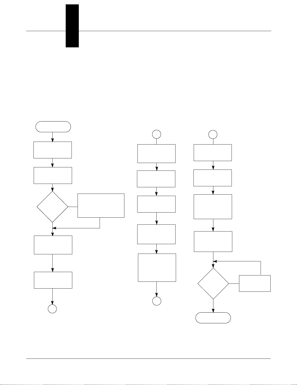
FIGURE 2-1. HART Tri-Loop
Installation Flowchart.
START
This section contains an installation flowchart, an overview of the
Model 333 HART Tri-Loop, and procedures for installation and wiring.
The suggested sequence of HART Tri-Loop installation and wiring is
shown in Figure 2-1.
A
B
Unpack the
HART Tri-Loop
Review the
HART Tri-Loop
Product Manual
Model
3095 MV
Installed?
Yes
Set the Model
3095MV Burst
Command Order
(page 2-8)
Set the Model
3095MV to Burst
HART Cmd 3
No
Install the
Model 3095 MV
(See Rosemount
Publication Number
00809-0100-4716)
INSTALL THE
HART TRI-LOOP
Review Installation
Considerations
(pages 2-4 to 2-5)
Mount the
Tri-Loop to
DIN Rail
Connect Channel
1 Wires from
Tri-Loop to
Control Room
(Optional)Connect
Channel 2 and/or
Channel 3 Wires
from Tri-Loop to
Control Room
COMMISSIONING
(Section 3)
Install HART Tri-
LoopConfigurator
onto Your PC
Configure
Tri-Loop to
Receive Model
3095 MV Burst
Commands
Connect wires
from Model 3095
MV to Tri-Loop
Burst Input
Pass
System
Test?
Check Trouble-
No
shooting
Procedures
B
A
Yes
DONE
2-1
Page 10
HART Tri-Loop HART-to-Analog Signal Converter
SYSTEM OVERVIEW
UNPACKING THE HART
TRI-LOOP
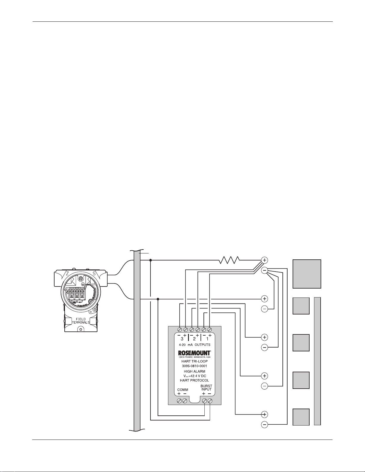
Figure 2-2 illustrates an installation where a Tri-Loop has been added
to a Model 3095 MV installation.
The Tri-Loop design allows three different rail mounting options:
asymmetrical 32mm G rail, symmetrical 35 3 7.5 mm top hat rail, and
symmetrical 35 3 15 mm top hat rail. Since the Tri-Loop is designed for
non-hazardous locations, the Tri-Loop can only be installed on the safe
side of an IS barrier.
In this type of installation, the Model 3095 MV is configured to output
HART Burst Command 3. The Tri-Loop converts each burst update to a
corresponding analog value for up to three process variables. Any of the
Model 3095 MV process variables can be provided via the Tri-Loop
(DP, AP, GP, PT, or flow).
For each desired analog output, a separate pair of wires is installed
from the Tri-Loop to the control room. However, Channel 1 wires must
be installed and powered for the Tri-Loop to operate.
The initial Model 3095 MV analog output is not altered by the Tri-Loop
installation.
When custom configuration Tri-Loops are shipped, the filled-out
configuration data sheet (CDS) is included in the box. If the CDS is
separated from the configured Tri-Loop, the serial number on the side
of the Tri-Loop can be matched with the serial number written on the
CDS. A label is also printed on the side of the Tri-Loop identifying
configuration information.
FIGURE 2-2. Example Tri-Loop
Installation Site.
Model 3095
NON-HAZARDOUS AREA
I.S. Barrier (See TransmitterManual
for I.S. Barrier Requirements)
250 Ω
Power
Supply
Pri-
mary
Sec-
ondary
Ter-
tiary
Control Inputs
2-2
Fourth
3095/3095_08A
Page 11
Installation
Initial Inspection
Model 3095 MV (or HART
Multivariable Device)
Alarms
1. Place the shipping containers on a secure bench and open them,
taking care not to damage the contents.
2. Review the packing list to verify that all equipment was received.
3. Inspect the equipment and report any shipping damage to the
carrier.
Before mounting the Tri-Loop in the control room, the Model 3095 MV
or HART Multivariable device must first be installed. Refer to the
Model 3095 MV product manual (00809-0100-4716) for information on
installing the Model 3095 MV.
Tri-Loops are configured with all channels to alarm in the same
direction. Alarm direction is configured at the factory, and cannot be
changed in the field. In addition, all Tri-Loop channels will alarm if a
Tri-Loop detects a sensor malfunction in the attached device.
Tri-Loops are ordered according to the desired alarm direction:
Tri-Loop Version Part Number
High Alarm Tri-Loop 03095-0810-0001
Low Alarm Tri-Loop 03095-0810-0002
High Alarm Tri-Loop, Custom
Configuration
Low Alarm Tri-Loop, Custom
Configuration
03095-0810-0003
03095-0810-0004
Failure Mode Ala rm vs.
Saturation Output Values
The failure mode alarm output levels differ from the output values that
occur when the measured value is outside the range points. When the
measured value is outside the range points, the analog output
continues to track the input value until reaching the saturation value
listed below; the output does not exceed the listed saturation value
regardless of the measured value. For example, for values outside the
4–20 range points, the output saturates at 3.9 mA or 20.8 mA.
When the Tri-Loop diagnostics detect a Tri-Loop failure or a Model
3095 MV malfunction, the analog outputs are set to an alarm value that
differs from the saturation value to allow for proper troubleshooting.
NOTE
The output values listed below can be altered by an analog output trim
procedure.
Level
Low 3.9 mA < 3.75 mA
High 20.8 mA > 21.75 mA
4–20 mA
Saturation Value
4–20 mA
Alarm Value
NOTE
If a Tri-Loop channel sets a range different than the attached device,
the Tri-Loop range will be used.
For example, if a Model 3095 MV sets the primary variable to DP with a
range of 0–250 inH
0, and the Tri-Loop Configurator sets
2
Tri-Loop channel 1 to receive this DP variable but enters a range of
0–100 inH20, the Tri-Loop will use the 0–100 inH20 range.
2-3
Page 12
HART Tri-Loop HART-to-Analog Signal Converter
INSTALLATION
CONSIDERATIONS
MECHANICAL
CONSIDERATIONS
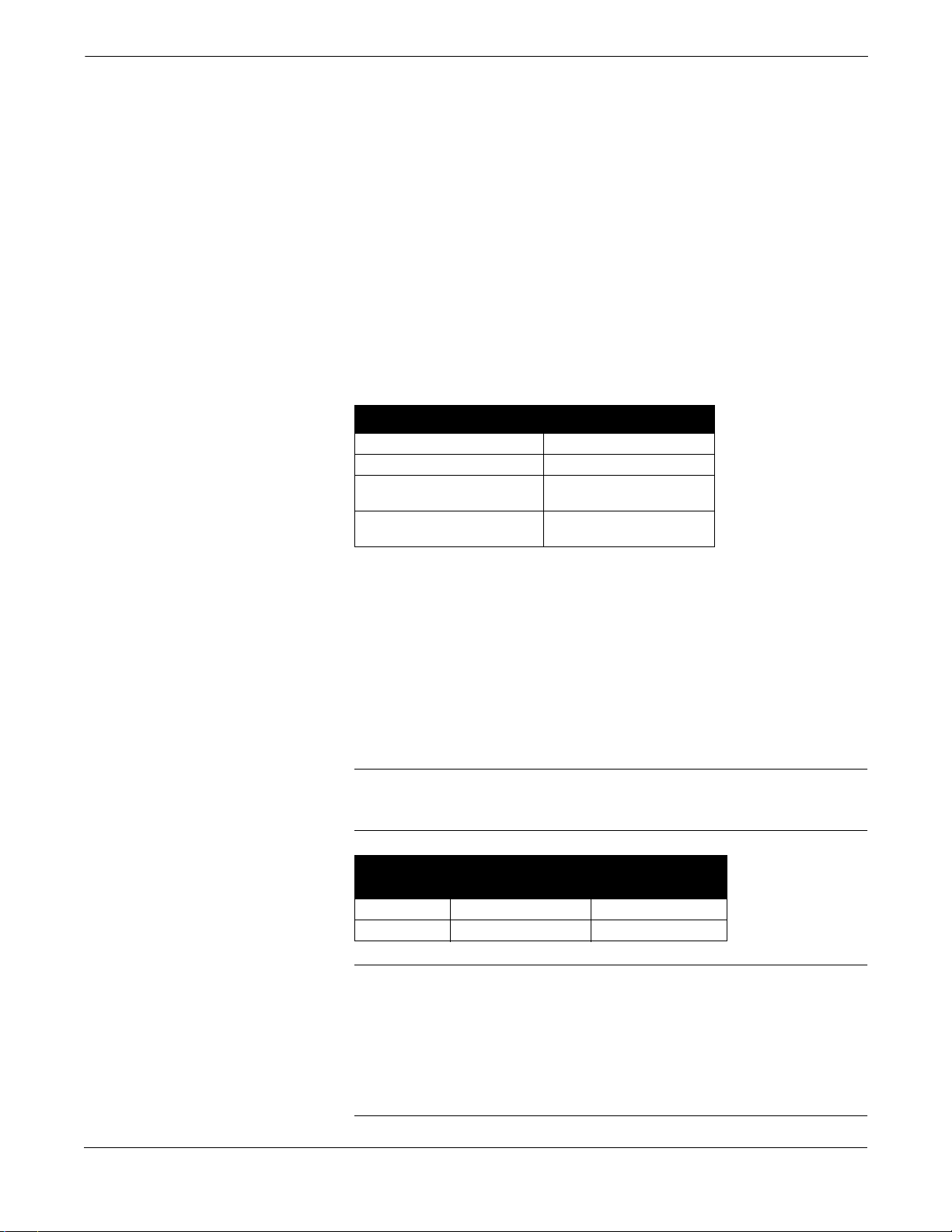
FIGURE 2-3. DIN Rail Mounting Options.
• Install the Tri-Loop in a location where it will be within the
operating temperature specification of 50 to 104 °F (10 to 40 °C).
NOT
• A Tri-Loop can
be installed in hazardous areas.
• Wiring need not be shielded, but twisted pairs should be used for
best results. Wiring should be between 24–12 AWG (solid or
stranded) and not exceed 1,000 feet (305 meters).
The Tri-Loop may be rail mounted on any of the DIN rails shown in
Figure 2-3. Simply snap the Tri-Loop onto the rail in the desired location.
3095-060AB
SYMMETRICAL 35 X 7.5 MM TOP HAT RAIL
ASYMMETRICAL 32MM G RAIL
3095-059AB
SYMMETRICAL 35 X 15 MM TOP HAT RAIL
3095-058AB
2-4
Page 13
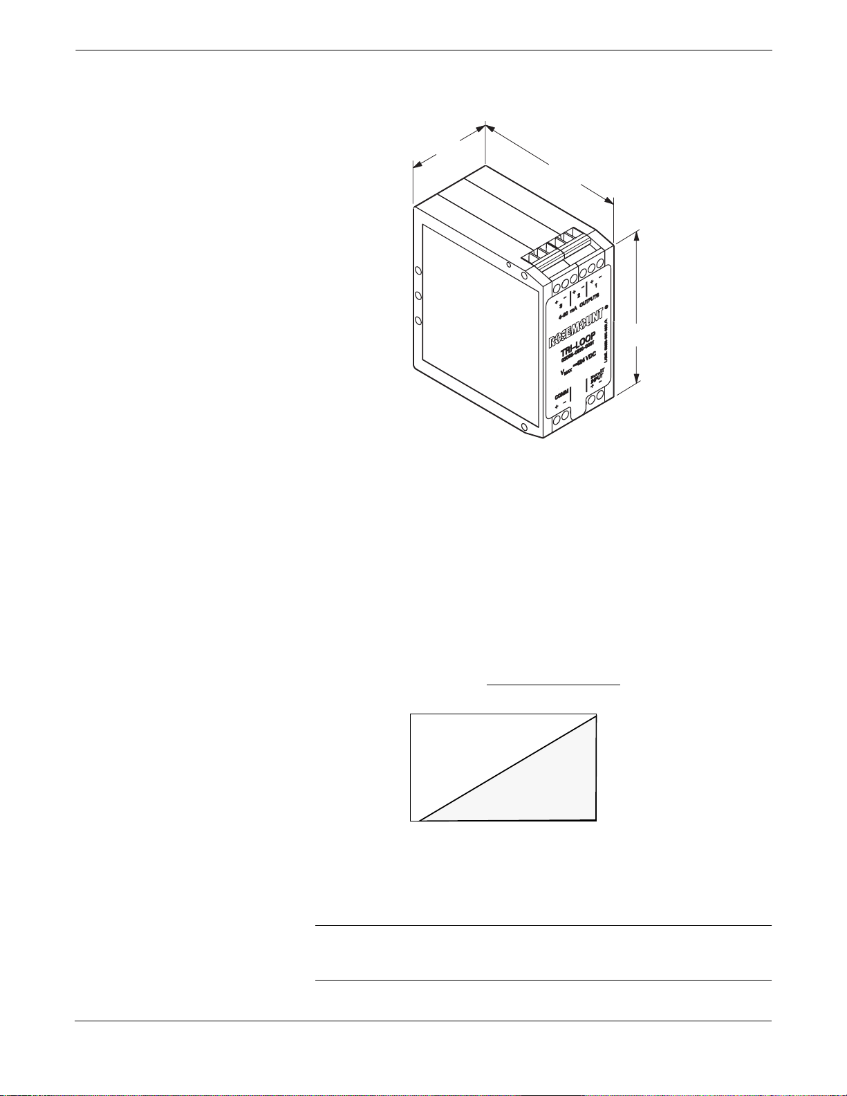
FIGURE 2-4. Tri-Loop Dimensions.
Installation
1.57
(40)
3.11
(79)
3.36
(86)
ELECTRICAL
CONSIDERATIONS
Po wer Supply
FIGURE 2-5. Power Supply
Load Limitations.
NOTE
Dimensions are in inches (millimeters).
3095-0810A01A
Figure 2-5 illustrates power supply load limitations for each channel of
the device. Each channel operates on terminal voltage of 11–42.4 V dc.
Channel 1 must be powered for Tri-Loop operation.
The dc power supply should provide power with less than 2% ripple.
The total resistance load is the sum of the resistance of the signal leads
and the load resistance of the controller, indicator, and related pieces.
Max. Loop Resistance = Power Supply Voltage–11.0
1800
1600
1400
1200
1000
800
600
400
Load (Ohms)
200
0
10 20
Power Supply Voltage, V dc
0.022
Operating Region
30
40
42.4
3051-0103A
NOTE
Wiring connections must be made in accordance with local or national
installation codes such as the NEC NFPA 70.
2-5
Page 14
HART Tri-Loop HART-to-Analog Signal Converter
INSTALLATION
EQUIPMENT
INSTALLATION
PROCEDURE
1. Review Installation
Considerations
2.Mount Tri-Loop on
DIN Rail
The following equipment and tools are not provided with the HART
Tri-Loop.
• Installation tools
• Wire between the control room and the Tri-Loop
• Wire between the Model 3095 MV and the Tri-Loop
• Power supply
• IS Barrier
1. Review the installation considerations described on pages 2-4
through 2-5 in this chapter to determine the location for the
HART Tri-Loop.
Explosions can cause death or serious injury. The HARTTriLoop is designed for installation in ordinary locations only.
Do NOT install the HART Tri-Loop in hazardous locations.
2. Mount the HART Tri-Loop on any of the following DIN rails:
• asymmetrical 32mm G rail,
• symmetrical 35 3 7.5 mm top hat rail
• symmetrical 35 3 15 mm top hat rail.
3. Wiring
3. Make wiring connections (see Figure 2-6).
NOTES
• Wiring need not be shielded, but twisted pairs should be used for
best results.
• To ensure communication, wiring should be between 24–12 AWG
(solid or stranded) and not exceed 1,000 feet (305 meters).
a. Run wire from Tri-Loop Channel 1 to control room, and secure
using screw clamps. Be sure to observe proper polarity. Include
proper loop resistance (see page 2-5).
b. (Optional) Run wire from Tri-Loop Channel 2 to control room,
and secure using screw clamps. Be sure to observe proper
polarity. Include proper loop resistance (see page 2-5).
c. (Optional) Run wire from Tri-Loop Channel 3 to control room,
and secure using screw clamps. Be sure to observe proper
polarity. Include proper loop resistance (see page 2-5).
d. Run wire from the Model 3095MV to BURST INPUT
connections, but do not complete connections at this time.
(See Figure 2-6).
NOTE
Tri-Loop commissioning will be much faster if the Tri-Loop does not
have to compete with the Model 3095 MV burst commands. We
therefore do not recommend completing the Burst Input connections
until the Tri-Loop is commissioned (Chapter 3).
2-6
Page 15
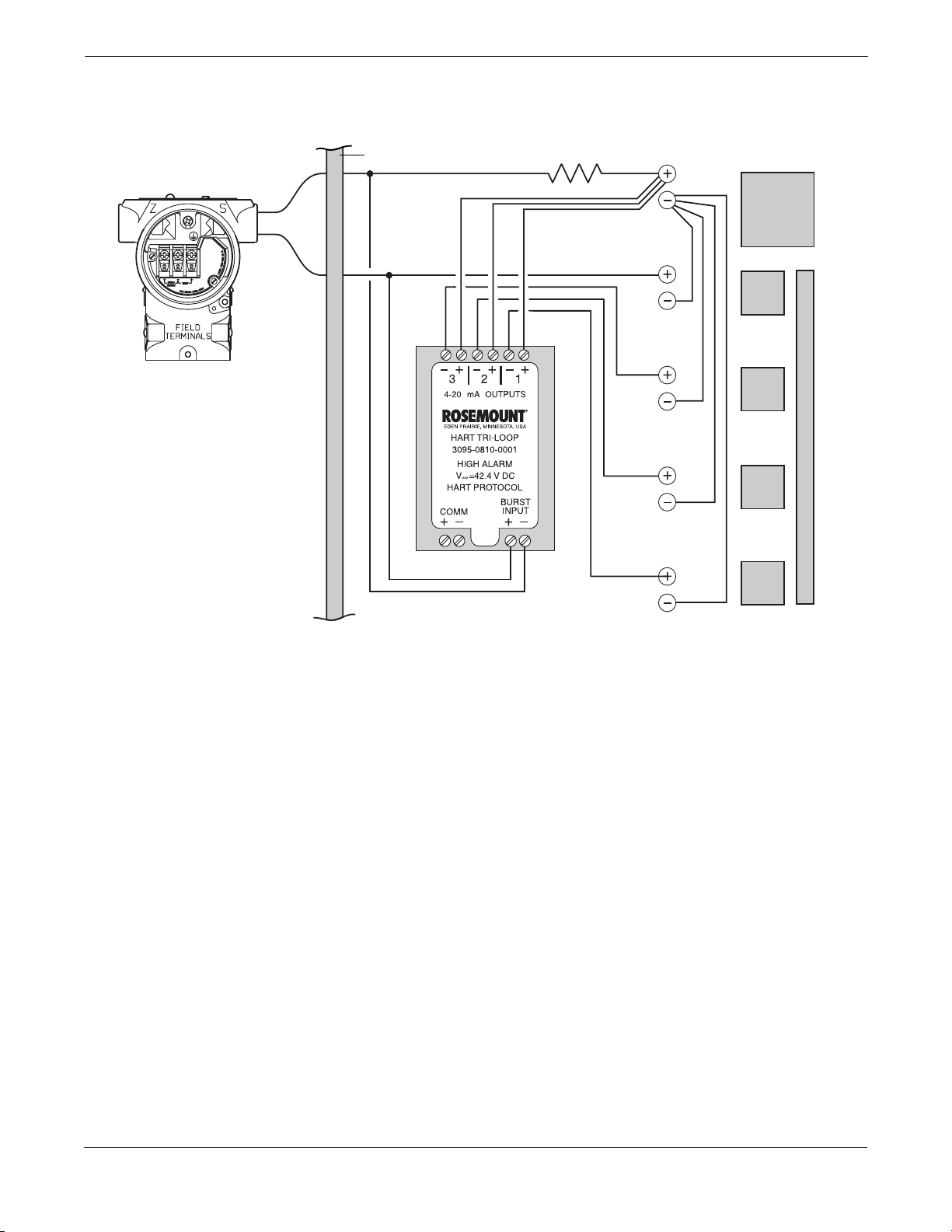
FIGURE 2-6. Tri-Loop Wiring
Connections (Parallel Wiring).
Installation
NON-HAZARDOUS AREA
I.S. Barrier (See Transmitter Manual
for I.S. Barrier Requirements)
Model 3095
250 Ω
Power
Supply
Pri-
mary
Sec-
ondary
Ter-
tiary
Fourth
Control Inputs
3095/3095_08A
2-7
Page 16

HART Tri-Loop HART-to-Analog Signal Converter
CONFIGURE THE MODEL
3095 MV FOR TRI-LOOP
OPERATION
Select Process Variables
Maintenance
A
nalog Output
R
ange Values...
FIGURE 2-7. Range Values Screen.
The following information is an abbreviated guide for using the Model
3095 MV Engineering Assistant (EA) to configure the Model 3095 MV
for operation with a HART Tri-Loop. For additional information on the
EA or the Model 3095 MV, refer to the Model 3095 MV product manual
(Rosemount publication number 00809-0100-4716).
This screen sets the range values for the primary variable, and also
allows for reassigning the process variable output order. This
determines both which process variables are burst by the Model 3095
MV, and in which order the variables are sent.
NOTE
The Primary Variable (Figure 2-7) is also assigned as the Model 3095
MV 4–20 mA analog output.
1. Using the Model 3095 MV EA, access the Range Values Screen
aintenance, Analog Output, Range Values...).
(M
2. Select Assign Variables, then set the desired variable order
(see Figure 2-8).
3. Record the selected process variables in Table 2-1.
FIGURE 2-8. Assign Variables Screen.
2-8
3095-30950116
Page 17

Record Model 3095 MV
Units
ransmitter
T
U
nits
FIGURE 2-9. Units Screen.
Installation
NOTE
The Tri-Loop will alarm if there is a unit mismatch between the Model
3095 MV and the Tri-Loop Channel.
To assist in Tri-Loop commissioning, (Section 3), we recommend that
you record the Model 3095 MV process variables and units in Table 2-1.
This screen sets the units for the five process variables:
Differential Pressure, Absolute Pressure, Gage Pressure, Process
Temperature, and Flow Applications.
1. Using the Model 3095 MV Engineering Assistant, access the
ransmitter, Units Screen.
T
2. If desired, change the displayed units. Modifying the information
on this screen and selecting OK immediately changes the
connected transmitter.
3. Record in Table 2-1 the selected units for each process variable.
TABLE 2-1. Table for entering Model 3095 MV Process Variables and Units.
Model 3095 MV
Process Variable
Primary
Secondary
Tertiary
Fourth
User-Assigned
Variables
User-Assigned
Units
3095-30950092
3095-30950097
2-9
Page 18

HART Tri-Loop HART-to-Analog Signal Converter
Set the Model 3095 MV to
Burst Mode
ransmitter
T
H
ART Output
B
urst Mode
FIGURE 2-10. Burst Mode Screen.
For the Tri-Loop to receive the process variables, the Model 3095 MV
must be set to Burst Command 3. Burst mode is compatible with use of
the analog signal. Burst mode applies only to the transmission of burst
data, and does not affect the way other Model 3095 MV data is
accessed.
1. Using the Model 3095 MV Engineering Assistant, access the
Burst Mode Screen.
2. If required, click on the Burst Mode Enabled box.
3. Select Dy
select OK.
namic Variables and Current (HART Cmd 3), then
2-10
3095-30950117
Page 19

Section
3 Commissioning
OVERVIEW
INSTALL THE TRI-LOOP
CONFIGURATOR
SOFTWARE
FIGURE 3-1. Tri-Loop Configurator
Software Equipment.
This section summarizes procedures needed to commission the HART
Tri-Loop HART-to-Analog Signal Converter.
The following tasks are described in this section:
• Install the Tri-Loop Configurator software
• Configure the Tri-Loop
• Complete Burst Input Connection
• Perform system test
The HART Tri-Loop Configurator software package is available with or
without the HART modem and connecting cables (see page 5-1 for part
numbers). The complete Configurator package contains four 3.5-in.
floppy disks, one HART modem, and a set of cables for connecting the
computer to the HART Tri-Loop (see Figure 3-1).
Laptop Computer
(not included)
Disk Containing HART
Tri-Loop Configurator
Software
HART Modem and Cables
3095.tif
3-1
Page 20

HART Tri-Loop HART-to-Analog Signal Converter
Minimum Equipment and
Software
• MS-DOS based 386 computer or above
• MS DOS
• 640K base RAM with 8 MB extended
• Microsoft
Windows 95
• Mouse or other pointing device (optional)
• Color computer display (optional)
• HART Tri-Loop Configurator Software, HART modem, set of
modem cables
®
5.0 or higher
®
Windows® 3.1, Windows for Workgroups 3.11, or
Installation Procedure
This procedure assumes that both DOS and Windows are already
installed.
NOTE
In this manual,
1. Power on the computer
2. After completion of boot-up procedures, verify that the computer
is in Microsoft Windows. If the computer is at the DOS prompt
(for example, C:\), type win
3. Insert the floppy disk containing the first HART Tri-Loop
Configurator Software into the personal computer disk drive.
4. Select F
the Run window. Depending on the disk drive, enter either
a: setup or b: setup, then click OK.
5. Follow the directions provided by the setup utility to install the
HART Tri-Loop Configurator Software. Setup may require 3 or 4
disks, depending on the computer operating system.
NOTE
The HART communications port can be either COM1 or COM 2. The
HART communications port must be different than the mouse port.
return
indicates to press the return or enter key.
return
to start Windows.
ile, then select Run from the Program Manager to display
3-2
Page 21

CONFIGURE THE
TRI-LOOP
Commissioning
NOTE
Close the Model 3095 MV Engineering Assistant before opening the
HART Tri-Loop Configurator Software. The Tri-Loop Configurator will
not communicate with a Tri-Loop if the EA is open or minimized.
Help Files
Connect the PC to the
Tri-Loop
The HART Tri-Loop Configurator Software contains a complete set of
on-line help instructions.
When the Tri-Loop software is running on your computer, these help
files are always available. To access these files, either click the Help
button on any Tri-Loop screen, press the F1 key, or select a topic from
the help menu.
When shipped from the factory, two quick-connect tabs are installed on
the Tri-Loop COMM ports.
1. Connect the computer to the HART Tri-Loop (see Figure 3-1 and
Figure 3-2).
a. Connect one end of the 9-pin to 9-pin cable to the HART
communications port on the personal computer.
b. Connect the other end of the 9-pin to 9-pin cable to the
HART modem.
c. Connect one end of the BNC cable to the HART modem.
d. Connect the mini-grabber cable to the other end of the BNC cable.
e. Connect the mini-grabbers to the two quick-connect tabs
installed on the Tri-Loop COMM ports as shown in Figure 3-2.
2. Power on the computer.
return
3. (If necessary) Type win
at the DOS prompt.
FIGURE 3-2. Connecting to the Tri-Loop.
Connect
Mini-grabber
Cables to
installed quick-
connect tabs
42.4 V DC
3-3
Page 22

HART Tri-Loop HART-to-Analog Signal Converter
Configuration Procedure
The following procedure outlines the major steps needed to configure a
Tri-Loop. For more detailed information, use the Configurator on-line
help screens.
1. Double click on the HART Tri-Loop Configurator Software icon.
2. Select T
ri-Loop, Connect to Tri-Loop to display the connect
screen, then connect to a Tri-Loop.
NOTE
If you are unable to connect to a Tri-Loop, see Table 4-1 on page 4-1 for
suggestions.
3. Select C
onfiguration, Configure Channels to display the HART
Tri-Loop Configuration Screen (Figure 3-3).
a. Click Channel 1, and select the process variable for this
exact
channel, desired range, and
Model 3095 MV units.
If required, click on the Enabled box so that the Tri-Loop
analog output will be enabled.
b. (Optional) Repeat step a for Channels 2 and 3.
c. Click device information, enter the desired tag, descriptor, and
message information, then select OK.
4. Select C
onfiguration, Save to Tri-Loop to send the configuration
to a Tri-Loop.
5. Select C
onfiguration, Open from Tri-loop to verify that the
configuration was correctly received. The Tri-Loop configuration
information will be displayed in the main window of the HART
Tri-Loop Configurator software.
6. If necessary, perform an analog output trim (T
ri-Loop, Trim
Outputs) for each enabled Tri-Loop analog output.
7. Complete the connection between the Model 3095 MV analog
output and the Tri-Loop Burst Input as illustrated in Figure 3-4.
8. Use a multimeter or the control room equipment to verify that
each new Tri-Loop channel is transmitting the Model 3095 MV
process variables.
FIGURE 3-3. HART Tri-Loop
ConfigurationScreen.
3-4
3095-30950702
Page 23

FIGURE 3-4. Tri-Loop Wiring Connections
Commissioning
NON-HAZARDOUS AREA
I.S. Barrier (See Transmitter Manual
for I.S. Barrier Requirements)
Model 3095
250 Ω
Power
Supply
Pri-
mary
Sec-
ondary
Ter-
tiary
Fourth
Control Inputs
3095/3095_08A
3-5
Page 24

HART Tri-Loop HART-to-Analog Signal Converter
MENU STRUCTURE
FIGURE 3-5. Configurator Menu Structure.
File Configuration Tri-Loop Diagnostics View Help
Figure 3-5 illustrates the complete menu structure for the HART
Tri-Loop Configurator Software. For information on any of these menu
items, refer to the Configurator on-line help files.
HART®Tri-Loop Configurator
Toolbar
Status Bar
Tri-Loop Infor mation
rror Info
E
eset
R
Tri-Loop Configurator Help Topics
About Tri-Loop Configurator...
Connect to Tri-Loop
isconnect from Tri-Loop
D
T
rim Outputs
ixed Outputs
F
ART Preambles
H
ecall Factory Default Trims
R
Configure Channels
Open from Tri-Loop
avetoTri-Loop
S
New Ctrl + N
Open... Ctrl + O
Save Ctrl + S
Save As...
1
filename.tlp
Exit
3-6
Page 25

Section
4 Troubleshooting
TABLE 4-1. Tri-Loop Troubleshooting
T able.
Table 4-1 provides troubleshooting suggestions for the most common
operating problems.
Symptom Corrective Action
No Communication
between the HART
Tri-Loop Configurator
Software and the Tri-Loop
Burst Commands not
received from Model3095
MV
Tri-Loop Channel is in
Alarm
Channel 1 operates
correctly, but Channel 2
(or Channel 3) does not
Win32S error
Runtime Error!
LOOP WIRING
• Close both EA software andTri-Loop Configurator software,
then restart the Tri-Loop Configurator software.
• HART protocol communication requires a loop resistance
value between250–1100 ohms, inclusive.
• Check foradequate voltageto theTri-Loop .(Channel1must be
powered for the Tri-Loop to operate.)
• Check for intermittentshorts,opencircuits, and multiple
grounds.
• Check for capacitanceacross the load resistor.Capacitance
should be less than 0.1 microfarad.
TRI-LOOP SOFTWARE INSTALLATION
• Verify computerreboot followed softwareinstallation.
• Verify correct COMM port selected.
• Verify laptopcomputer is not in low energy mode
(certain laptopsdisable allCOMMports in lowenergy mode).
• Did you install software onto Windows NT platform?
(Configurator softwarewillonlywork with Windows 3.1,
Windows forWorkgroups 3.11, or Windows 95.)
• Check ifHART driverwassubsequently over-written during a
Model 3095MVEngineering Assistant installation. If thishas
occurred, reinstalltheConfigurator software.
• Check the DEVICEHIGH statement in the CONFIG.SYS
statement as explained in the Configurator “readme” file.
• Verify the Model3095MVissettoBurst Command 3.
• Check foradequate voltageto theTri-Loop .(Channel1must be
powered for the Tri-Loop to operate.)
• Check for intermittentshorts,opencircuits, and multiple
grounds.
• HART protocol communication requires a loop resistance
value between 250–1100 ohms, inclusive. Typically, the
required resistanceisinstalled during the Model 3095 MV
installation.
• Use the HART Tri-Loop Configurator, and select
D
iagnostics, Error Info to determine the causeofthealarm.
For information on any error message, use theConfigurator
on-line help files.
• Check for properloop resistance for the channel.Each
channel must have it’s own powersupply and required loop
resistance (see page 2-5).
• If youreceive aWin32s orRuntime error, removeWin32s and
reinstall the Configuratorsoftware as explained in the
Configurator “readme”file.
4-1
Page 26

HART Tri-Loop HART-to-Analog Signal Converter
4-2
Page 27

Section
ORDERING
INFORMATION
5 Specifications and
Reference Data
This section contains the following reference data for the HART
Tri-Loop HART-to-Analog Signal Converter:
• Ordering information
• Specifications
• Configuration Data Sheet (00806-0100-4754)
Model No.
(Part No.)
Model 333U
(03095-0810-0001)
Model 333D
(03095-0810-0002)
Model 333UC2
(03095-0810-0003)
Model 333DC2
(03095-0810-0004)
03095-0821-0001 HART Tri-Loop Configurator Software–
03095-0820-0002 HART Tri-Loop Configurator Software–
03095-5105-0001 HART Modem and Cables.
High Alarm Tri-Loop, Standard Configuration.
Low Alarm Tri-Loop, Standard Configuration.
High Alarm Tri-Loop, Custom Configuration.
Requires a completed Configuration Data
Sheet (00806-0100-4754).
Low Alarm Tri-Loop, Custom Configuration.
Requires a completed Configuration Data
Sheet (00806-0100-4754).
Site License, HART Modem, Cables.
Site License.
Description
SPECIFICATIONS
Functional
Specifications
NOTE
There are no user-serviceable parts for the HART Tri-Loop.
Service
Accessory product for the Model 3095 MV and Model 3244MV.
Output
One, two, or three 4–20 mA output signals,
user-selectable for DP, AP, GP, PT, or flow.
Power Supply
External power supply required for each channel. Channel 1 must be
powered for Tri-Loop operation. Each channel operates on terminal
voltage of 11–42.4 V dc.
Turn-on Time
Analog signals will be within specifications five seconds after power is
applied to Tri-Loop.
Installation Locations
Approved for FM ordinary locations.
Approved for CSA ordinary locations.
5-1
Page 28

HART Tri-Loop HART-to-Analog Signal Converter
Load Limitations
Loop resistance is determined by the voltage level of the external power
supply, as described by:
Temperature Limits
Ambient
50 to 104 °F (10 to 40 °C).
Storage
–40 to 158 °F (–40 to 70 °C).
Humidity Limits
0–95% non-condensing relative humidity.
Failure Mode Alarm
If Tri-Loop diagnostics detect a transmitter malfunction or a Tri-Loop
failure, the analog signal will be driven either below 3.75 mA or above
21.75 mA to alert the user. The high or low alarm signal is selectable by
the Tri-Loop Model Number.
Max. Loop Resistance = Power Supply Voltage–11.0
1427
1200
1000
800
600
400
Load (Ohms)
200
0
10 20
Power Supply Voltage, V dc
0.022
Operating Region
30
40
42.4
Perf ormanc e
Specifications
Physical Specifications
NOTE
The performance specifications below are for the HART Tri-Loop only.
Reference Accuracy
±0.045% of span.
Ambient Temperature Effect per 50 °F (28 °C)
±0.15% of span.
Stability
±0.1% of span for 12 months.
Analog Output Update
Tri-Loop responds to every HART burst update.
(Typical transmitter burst update rate: 0.3 to 0.5 s.)
Tri-Loop Response Time (after each burst update)
Channel 1–120 ms; Channel 2–220 ms; Channel 3–320 ms.
Total Response Time
Typical response time from sensor change to transmitter to Tri-Loop
analog update: 0.7 to 1.0 s.
Electrical Connections
Screw clamps. Accepts 24-12 AWG solid or stranded wire.
Dimensions
1.57 3 3.11 3 3.36 in. (40 3 79 3 85,5 mm)
DIN Rail Mounting Options
Asymmetrical 32mm G rail, symmetrical 35 3 7.5 mm top hat rail, or
symmetrical 35 3 15 mm top hat rail.
Weight
0.27 lb (0,12 kg)
5-2
Page 29

Specifications and Reference Data
CONFIGURATION DATA
SHEET 00806-0100-4754
Complete this data sheet to define a custom configuration for the Madel 333 HART Tri-Loop.
Unless specified, the Tri-Loop will ship with the default values identified by the ★ symbol.
CONFIGURATION DATA SHEET
Customer: ______________________________________________________________________________
Customer P.O. No.: _____________________________________________________________________
Customer Line Item: _____________________________________________________________________
Model No. (select one) M High Alarm – Model No. 333UC2 M Low Alarm – Model No. 333DC2
(previously: 03095-0810-0003) (previously: 03095-0810-0004)
DEVICE INFORMATION (optional)
Tag: |___|___|___|___|___|___|___|___|
(8 characters)
Descriptor: |___|___|___|___|___|___|___|___|___|___|___|___|___|___|___|___|
(16 characters)
Message: |___|___|___|___|___|___|___|___|___|___|___|___|___|___|___|___|
|___|___|___|___|___|___|___|___|___|___|___|___|___|___|___|___|
(32 characters)
Date: |___|___| |___|___|___| |___|___|
(dd) (mmm) (yy)
CHANNEL 1
Channel Status (select one): M
Assigned Variable (select one)
(1)
Variable Range: Zero (4 mA) Value _________________________
Variable Units ________________________________________
(1) Verify process variable assignment for your instrument.
(2) This information must be completed for each enabled channel before the CDS can be accepted.
(3) Selected units must match device units or the Tri-Loop will alarm. Verify unit assignment for your instrument.
Enabled M Disabled ★
: M Primary Variable M Secondary Variable ★
M Ter tiar y Variable M Fourth Variable
Full Scale (20 mA) Value ____________________
For RMD internal use only:
House Order No: __________________________
Line Item No: __________________________
(2)
(2)
(2) (3)
Tri-Loop Serial No: __________________________
5-3
Page 30

HART Tri-Loop HART-to-Analog Signal Converter
CHANNEL 2
Channel Status (select one): M
Assigned Variable (select one)
(1)
Enabled M Disabled ★
: M Primary Variable M Secondary Variable
M Ter tiar y Variable ★ M Fourth Variable
Variable Range: Zero (4 mA) Value _________________________
Full Scale (20 mA) Value ____________________
Variable Units ________________________________________
(2)
(2)
(2) (3)
CHANNEL 3
Channel Status (select one): M Enabled M Disabled ★
Assigned Variable (select one)
(1)
: M Primary Variable M Secondary Variable
M Ter tiar y Variable M Fourth Variable ★
Variable Range: Zero (4 mA) Value _________________________
Full Scale (20 mA) Value ____________________
Variable Units ________________________________________
(1) Verify process variable assignment for your instrument.
(2) This information must be completed for each enabled channel before the CDS can be accepted.
(3) Selected units must match device units or the Tri-Loop will alarm. Verify unit assignment for your instrument.
(2)
(2)
(2) (3)
5-4
Page 31

Appendix
A Model 3244MV
OVERVIEW
This appendix outlines the procedures necessary to install and
commission a Model 3244MV Smart Temperature Transmitter for use
with a HART Tri-Loop.
Use the HART Tri-Loop in conjunction with a Model 3244MV in
operation with two sensors to acquire an independent 4–20 mA analog
output signal for each sensor input. During normal operation, the
3244MV outputs four digital process variables: sensor 1, sensor 2,
differential temperature, and transmitter terminal temperature. The
HART Tri-Loop divides the digital signal and outputs any or all of these
variables into as many as three separate 4–20 mA analog channels.
You can also use the Tri-Loop with the 3244MV configured for
differential temperature measurement or Hot Backup (see Special
Considerations on page A-3).
Installation
Figure A-1 basic installation information. For complete installation
information and procedures, refer to Section 2 Installation.
FIGURE A-1. HART Tri-Loop Installation Flowchart.
START
A
B
Unpack the
HART Tri-Loop
Review the
HART Tri-Loop
Product Manual
Model
3244MV
Installed
Yes
Set the Model
3244MV Burst
Command Order
Set the Model
3244MV to Burst
Mode
No
Model 3244MV
(See Rosemount
Publication Number
00809-0100-4724)
Install the
INSTALL THE
HART TRI-LOOP
(See Section 2)
Review Installation
Considerations
(Pages 2-4 to 2-5)
Mount the
Tri-Loop to
DIN Rail
Run Wires from
Model 3244MV
to Burst Input
Terminals
Install Channel 1
Wires from
Tri-Loop to the
Control Room
(Optional) Install
Channel 2 and/or
Channel 3 Wires
from Tri-Loop to
the Control Room
COMMISSIONING
(See Section 3)
Configure
Tri-Loop to
Receive 3244MV
Burst Commands
Pass
System
Test
Yes
DONE
Check Trouble-
No
shooting
Procedures
A
B
A-1
Page 32

HART Tri-Loop HART-to-Analog Signal Converter
COMMISSIONING THE
TRANSMITTER
Set the Transmitter to
Burst Mode
To prepare a Model 3244MV for use with a HART Tri-Loop, you must
configure the transmitter to Burst Command 3, and set the order of the
process variables. In burst mode, the transmitter provides digital
information for the analog current in mA to the Tri- Loop. The Tri-Loop
divides the signal into separate 4–20 mA loops for the primary,
secondary, tertiary, and fourth variables. When using the 3244MV in
conjunction with the Tri-Loop, you must also consider the configuration
of the differential temperature and hot backup features, if used. To
commission a Model 3244MV for use with a HART Tri-Loop, perform
the following procedures.
NOTE
These procedures assume that the sensor and transmitter are
connected, powered, and functioning properly, and that a Model 275
HART Communicator is connected to the transmitter control loop and
is communicating successfully. For information about connecting the
communicator to the transmitter, refer to the Models 3144 and 3244MV
Product Manual, Rosemount publication number 00809-0100-4724.
1. From the Home screen, Select 1 Device setup, 4 Detailed setup,
3 Output condition, 2 HART output, 4 Burst option to prepare to
set the transmitter to Burst Mode.
The communicator displays the Burst option screen.
2. Select Process vars/crnt.
The communicator returns to the HART output screen.
3. Select 3 Burst mode to prepare to enable Burst Mode.
The communicator displays the Burst mode screen.
4. Select On to enable burst mode.
The communicator returns to the HART output screen.
5. Select “SEND” to download the new configuration information
to the transmitter.
Set Process Variable
Output Order
A-2
A-2
1. From the Home screen, select 1 Device setup, 1 Process variables,
7 Variable re-map. Select “OK” to set the control loop to manual.
The communicator displays the Primary Variable screen.
2. Select the item you wish to set as the primary variable at the
“Select PV” prompt.
3. Repeat step 2 for the SV, TV, and QV.
The communicator displays the Variable mapping screen.
4. Select “OK” to accept the order to which the variables are
mapped, or “ABORT” to abort the entire procedure.
NOTE
Take careful note of the process variable output order. You must
configure the Tri-Loop to read the variables in the same order.
5. Select “OK” to return the control loop to automatic control.
Page 33

Appendix A
Special Considerations
To initiate operation between a Model 3244MV and the Tri-Loop, you
must consider the configuration of the both the Differential
Temperature and the Hot Backup features, if used. For complete
information regarding the Differential Temperature and Hot Backup
features, refer to the Models 3144 and 3244MV Product Manual,
Rosemount publication number 00809-0100-4724.
Differential Temperature Measurement
To enable the differential temperature measurement feature of a
3244MV operating in conjunction with the Tri-Loop, adjust the range
end points of the corresponding channel on the Tri-Loop to include zero.
For example, if you wish the secondary variable of the 3244MV to
report differential temperature, configure the transmitter accordingly
(see Set Process Variable Output Order on page A-2), and adjust
the corresponding channel of the Tri-Loop so one range end point is
negative and the other is positive.
Hot Backup
To enable the Hot Backup feature of a Model 3244MV operating in
conjunction with the Tri-Loop, ensure that the output units of the
sensors are the same as the units of the Tri-Loop. You may use any
combination of RTDs or thermocouples as long as the units of both
match the units of the Tri-Loop.
NOTE
When configured for Hot Backup, if sensor 1 (primary) fails, sensor 2
automatically becomes the primary. An alarm does not occur unless
sensor 2 also fails.
A-3
A-3
Page 34

HART Tri-Loop HART-to-Analog Signal Converter
A-4
Page 35

Appendix
B HART®Communicator
INTRODUCTION
COMMUNICATING WITH A
HART TRI-LOOP
This appendix provides basic communicator information on the HART
Communicator Model 275 when used with a Tri-Loop. Included in this
appendix are a menu tree, a table of fast key sequences, and
information on using the HART communicator.
For more complete information on the HART Communicator, refer to
the HART Communicator Product Manual 00809-0100-4275.
This brief appendix will familiarize you with the HART Communicator
but is not meant to replace the HART Communicator product manual.
The standard configuration for a Model 275 HART Communicator is to
search for devices with HART address 0. The HART Tri-Loop, which is
designed to work in conjunction with other HART devices, defaults to
HART address 1. Therefore, before a HART Communicator can
communicate with a HART Tri-Loop, you must first change a HART
Communicator setting from "always poll" to "digital poll."
1. Select "4" Utility.
2. Select "1" Configure Communication.
3. Select "1" Polling.
4. Select "Digital Poll."
B-1
Page 36

HART Tri-Loop HART-to-Analog Signal Converter
FIGURE B-1. HART Communicator Menu Tree for the Tri-Loop.
Online Menu
1 DEVICE SETUP
1 DIAGNOSTICS/
SERVICE
2 BASIC SETUP
1 TEST DEVICE
2 LOOP TEST
3 CALIBRATION
4 D/A TRIM
1Tag
2 CONFIGURE
CHANNELS
3DEVICE
INFORMATION
1 Status
2Reset
1 CH1
2 CH2
3 CH3
1 CONFIGURE
CHANNELS
2 RECALL FACTORY
TRIM
1 CH1
2 CH2
3 CH3
1 CONFIGURE CH1
2 CONFIGURE CH2
3 CONFIGURE CH3
1 Model
2DevID
3Tag
4Date
5Descriptor
6 Message
7 Final Asmbly Num
8 REVISION #s
14mA
2 20mA
3 Other
4End
1 CONFIGURE CH1
2 CONFIGURE CH2
3 CONFIGURE CH3
1 CH1
2 CH2
3 CH3
4All
1 Burst Variable
2Units
3LRV
4URV
5 Enabled
1 Universal Rev
2 Fld Dev Rev
3 Software Rev
1BurstVariable
2Units
3LRV
4URV
5 Enabled
3DETAILED
SETUP
4REVIEW
1OUTPUT
CONDITION
2DEVICE
INFORMATION
Model
Manufacturer
Dev ID
Tag
Descriptor
Messsage
Date
Final
Asmbly Num
Universal Rev
Fld Dev Rev
Software Rev
Poll Addr
Num Req Preams
1 ANALOG
OUTPUT
2 HART OUTPUT
1 Model
2DevID
3Tag
4Date
5 Descriptor
6 Message
7 Final Asmbly
Num
8 REVISION #s
1LOOPTEST
2 D/A TRIM
3 SCALED D/A
TRIM
1 Poll Addr
2 Num Req Preams
3NumRspPreams
1UniversalRev
2 Fld Dev Rev
3 Software Rev
1 CH1
2 CH2
3 CH3
1 CH1
2 CH2
3 CH3
1 CH1
2 CH2
3 CH3
14mA
220mA
3 Other
4End
1 Proceed
2 Change
B-2
Page 37

TABLE B-1. HART Fast Key
Sequences for the Tri-Loop.
Appendix B
Function
20 mA (Loop Test) 1, 2, 1, 2 Fld Dev Rev (Basic Setup) 2, 3, 8, 2
20 mA (Output Condition) 3, 1, 1, 1, 1, 2 Fld Dev Rev (Detailed Setup) 3, 2, 8, 2
4mA(LoopTest) 1,2,1,1 LRV(Calibration) 1,3,1,1,3
4 mA (Output Condition) 3, 1, 1, 1, 1, 1 LRV (Configure Channels) 2, 2, 1, 3
All (Calibration) 1, 3, 2, 4 Message (Basic Setup) 2, 3, 6
Burst Variable (Calibration) 1, 3, 1, 1, 1 Message (Detailed Setup) 3, 2, 6
Burst Variable (Configure Channels) 2, 2, 1, 1 Model (Basic Setup) 2, 3, 1
CH1 (Calibration) 1, 3, 2, 1 Model (Detailed Setup) 3, 2, 1
CH1(D/ATRIM) 1,4,1 NumReqPreams 3,1,2,2
CH1 (Output Condition) 3, 1, 1, 2, 1 Num Rsp Preams 3, 1, 2, 3
CH2 (Calibration) 1, 3, 2, 2 Other (Loop Test) 1, 2, 1, 3
CH2 (D/A TRIM) 1, 4, 2 Other (Output Condition) 3, 1, 1, 1, 1, 3
CH2 (Output Condition) 3, 1, 1, 2, 2 Poll Addr 3, 1, 2, 1
CH3 (Calibration) 1, 3, 2, 3 Proceed (Scaled D/A Trim) 3, 1, 1, 3, 1, 1
CH3 (D/A TRIM) 1, 4, 3 Reset 1, 1, 2
CH3 (Output Condition) 3, 1, 1, 2, 3 Software Rev (Basic Setup) 2, 3, 8, 3
Change (Scaled D/A Trim) 3, 1, 1, 3, 1, 2 Software Rev (Detailed
Date (Basic Setup) 2, 3, 4 Status 1, 1, 1
Date (Detailed Setup) 3, 2, 4 Tag 2, 1
Descriptor (Basic Setup) 2, 3, 5 Tag (Basic Setup) 2, 3, 3
Descriptor (Detailed Setup) 3, 2, 5 Tag (Detailed Setup) 3, 2, 3
Dev ID (Basic Setup) 2,3, 2 Units (Calibration) 1, 3, 1, 1, 2
Dev ID (Detailed Setup) 3, 2, 2 Units (Configure Channels) 2, 2, 1, 2
Enabled (Calibration) 1, 3, 1, 1, 5 Universal Rev (Basic Setup) 2, 3, 8, 1
Enabled (Configure Channels) 2, 2, 1, 5 Universal Rev (Detailed
End(LoopTest) 1,2,1,4 URV(Calibration) 1,3,1,1,4
End (Output Condition) 3, 1, 1, 1, 1, 4 URV (Configure Channels) 2, 2, 1, 4
Final Asmbly Num (Basic Setup) 2, 3, 7
Final Asmbly Num (Detailed Setup) 3, 2, 7
HART Communicator
Fast Key Sequences
Function HART Communicator
Fast Key Sequences
Setup)
Setup)
3, 2, 8, 3
3, 2, 8, 1
B-3
Page 38

HART Tri-Loop HART-to-Analog Signal Converter
CONNECTIONS AND
HARDWARE
FIGURE B-2. Rear Connection Panel
with Optional NiCad Recharger Pack.
The HART Communicator Model 275 can interface with a transmitter
from the control room, the instrument site, or any wiring termination
point in the loop through the rear connection panel as shown in Figure
B-2. To communicate, connect the HART Communicator in parallel
with the instrument or load resistor. The connections are non-polarized.
Explosions can result in death or serious injury. Do not
make connections to the serial port or NiCad recharger jack
in an explosive atmosphere.
Loop Connection Ports
Optional NiCad
Recharger Jack
Serial Port
Explosions can result in death or serious injury. Before
connecting the HART Communicator in an explosive
atmosphere, make sure the instruments in the loop are
installed in accordance with intrinsically safe or
nonincendive field wiring practices.
NOTE
The HART Communicator needs a minimum of 250 ohms resistance in
the loop to function properly. The HART Communicator does not
measure loop current directly.
275-008AB
B-4
Page 39

FIGURE B-3. Wiring Connections.
Appendix B
User-Provided
Power Supply
(see page 2-5)
HART COMMUNICATOR
3095-3095_2A
B-5
Page 40

HART Tri-Loop HART-to-Analog Signal Converter
COMMUNICATOR KEYS
FIGURE B-4. The HART Communicator.
The keys of the HART Commuincator include action, function,
alphanumeric, and shift keys
Function Keys
Action Keys
Alphanumeric Keys
Shift Keys
Action Keys As shown in Figure B-4, the action keys are the six blue, white, and
black keys located above the alphanumeric keys. The function of each
key is described as follows:
ON/OFF Key
Use this key to power the HART Communicator. When the
communicator is turned on, it searches for a transmitter on the 4–20
mA loop. If a device is not found, the communicator displays the
message, “No Device Found. Press OK.”
If a HART-compatible device is found, the communicator displays the
Online Menu with device ID and tag.
Directional Keys
Use these keys to move the cursor up, down, left, or right. The right
arrow key also selects menu options, and the left arrow key returns to
the previous menu.
HOT Key
Use this key to quickly access important, user-selectable options when
connected to a HART-compatible device. Pressing the Hot Key turns
the HART Communicator on and displays the Hot Key Menu.
See Customizing the Hot Key Menu in the HART Communicator
manual for more information.
275-011AB
B-6
Page 41

Appendix B
Function Keys Use the four software-defined function keys, located below the LCD, to
perform software functions. On any given menu, the label appearing
above a function key indicates the function of that key for the current
menu. As you move among menus, different function key labels appear
over the four keys. For example, in menus providing access to on-line
help, the label may appear above the F1 key. In menus providing
access to the Online Menu, the label may appear above the F3 key.
HELP
HOME
Simply press the key to activate the function. See your HART
Communicator manual for details on specific function key definitions.
Alphanumeric and Shift Keys The alphanumeric keys (Figure A-5) perform two functions: the fast
selection of menu options and data entry.
FIGURE B-5. HART Communicator
Alphanumeric and Shift Keys.
FIGURE B-6. Data Entry Key Sequence.
Data Entry
Some menus require data entry. Use the alphanumeric and shift keys to
enter all alphanumeric information into the HART Communicator. If
you press an alphanumeric key alone from within an edit menu, the
bold character in the center of the key appears. These large characters
include the numbers zero through nine, the decimal point (.), and the
dash symbol (—).
To enter an alphabetic character, first press the shift key that
corresponds to the position of the letter you want on the alphanumeric
key. Then press the alphanumeric key. For example, to enter the letter
“R,” press and release the right shift key, then press and release the “6”
key (see Figure B-6). Do not press these keys simultaneously.
B-7
Page 42

HART Tri-Loop HART-to-Analog Signal Converter
Fast Key Sequences
Fast Key Sequence Conventions The fast key sequences for the Model 275 use the following conventions
Fast Key Sequence Example HART fast key sequences are made up of the series of numbers
HART fast key sequences provide quick on-line access to transmitter
variables and functions. Instead of stepping your way through the menu
structure using the action keys, you can press a HART fast key sequence
to move from the Online Menu to the desired variable or function. Onscreen instructions guide you through the rest of the screens.
for their identification:
1 through 9–Refer to the keys located directly below the dedicated
keypad.
Left Arrow–Refers to the left arrow directional key.
corresponding to the individual options in each step of the menu
structure. For example, from the Online Menu you can change the Poll
Addr. Following the menu structure, press 1 to reach Device Setup,
press 3 for Detailed Setup, press 1 for Output Condition, press 2 for
HART Output, and 1 for Poll Addr. The corresponding HART fast
key sequence is 1, 3, 1, 2, 1.
HART fast keys are operational only from the Online Menu. If you use
them consistently, you will need to return to the Online Menu by
pressing (F3) when it is available. If you do not start at the Online
Menu, the HART fast key sequences will not function properly.
Use Table B-1, an alphabetical listing of every on-line function, to find
the corresponding HART fast key sequences. These codes are applicable
only to Level Controller and the HART Communicator.
HOME
MENUS AND FUNCTIONS
Main Menu
The HART Communicator is a menu driven system. Each screen
provides a menu of options that can be selected as outlined above, or
provides direction for input of data, warnings, messages, or other
instructions.
When the HART Communicator is turned on, one of two menus will
appear. If the HART Communicator is connected to an operating loop,
the communicator will find the device and display the Online Menu (see
below). If it is not connected to a loop, the communicator will indicate
that no device was found. When you press OK (F4), it will display the
Main menu.
The Main menu provides the following options:
• Offline–The Offline option provides access to offline configuration
data and simulation functions.
• Online–The Online option checks for a device and if it finds one,
brings up the Online Menu.
• Transfer–The Transfer option provides access to options for
transferring data either from the HART Communicator (memory)
to the transmitter (device) or vice versa. Transfer is used to move
off-line data from the HART Communicator to the transmitter, or
to retrieve data from a transmitter for off-line revision.
B-8
Page 43

Appendix B
NOTE
Online communication with the transmitter automatically loads the
current transmitter data to the HART Communicator. Changes in online data are made active by pressing SEND (F2). The transfer function
is used only for off-line data retrieval and sending.
• Frequency Device–The Frequency Device option displays the
frequency output and corresponding pressure output of currentto-pressure transmitters.
• Utility–The Utility option provides access to the contrast control
for the HART Communicator LCD screen and to the autopoll
setting used in multidrop applications.
Once selecting a Main menu option, the HART Communicator provides
the information you need to complete the operation. If further details
are required, consult the HART Communicator manual.
Online Menu
The Online Menu can be selected from the Main menu as outlined
above, or it may appear automatically if the HART Communicator is
connected to an active loop and can detect an operating transmitter.
NOTE
The Main menu can be accessed from the Online Menu. Press the left
arrow action key to deactivate the on-line communication with the
transmitter and to activate the Main menu options.
When configuration variables are reset in the on-line mode, the new
settings are not activated until the information is sent to the
transmitter. Press SEND (F2) when it is activated to update the process
variables of the transmitter.
On-line mode is used for direct evaluation of a particular meter, reconfiguration, changing parameters, maintenance, and other functions.
B-9
Page 44

HART Tri-Loop HART-to-Analog Signal Converter
Diagnostic Messages
The following pages contain a list of messages used by the HART
Communicator (HC) and their corresponding descriptions.
Variable parameters within the text of a message are indicated with
<variable>.
Reference to the name of another message is identified by
<message>.
Message Description
Add item for ALL device
typesoronlyforthisONE
device type.
Command Not
Implemented
Communication Error Either a device sends back a response indicating that the
Configuration memory
not compatible with
connected device
Device Busy The connected device is busy performing another task.
Device Disconnected Device fails to respond to a command.
Device write protected Device is in write-protect mode. Data can not be written.
Device write protected.
Do you still want to s hut
off?
Display value of variable
on hotkey menu?
Download da ta from
configuration memory to
device
Exceed field width Indicates that the field width for the current arithmetic variable
Exceed precision Indicates that the precision for the current arithmetic variable
Ignore next 50
occurrences of status?
Illegal character An invalid character for the variable type was entered.
Illegal date The day portion of the date is invalid.
Illegal month The month portion of the date is invalid.
Illegal year The year portion of the date is invalid.
Incomplete exponent The exponentof a scientific notation floating point variable is
Incomplete field The value entered is not complete for the variable type.
Looking for a device Pollingfor multidropped devices at addresses 1–15.
Asks the user whether the hot key item being added should be
added for all device types or only for the type of device that is
connected.
The connected device does not support this function.
message it received was unintelligible,or the HC cannot
understand the response from the device.
The configuration stored in memor y is incompatible with the
device to which a transfer has been requested.
Deviceis in write-protect mode. Press YES to turn the HC off and
lose the unsent data.
Asks whether the value of the variable should be displayed
adjacentto its labelon the hotkeymenu if the item being added to
the hotkey menu is a variable.
Promptsuser to press SEND softkeyto initiateamemory to device
transfer.
exceeds the device- specified description edit format.
exceeds the device- specified description edit format.
Asked after displaying device status. Softkey answer determines
whether next 50 occurrences of device status will be ignored or
displayed.
incomplete.
B-10
Page 45

Appendix B
Message Description
Mark as read only
variable on hotkey
menu?
No device configuration
in configuration memory
No Device Found Pollof address zero fails to find a device,or poll of all addresses
Nohotkey menuavailable
for this device.
No offline devices
available.
No simulation devices
available.
NoUPLOAD_VARIABLES
in ddl for this device
No Valid Items The selected menu or edit display contains no valid items.
OFF KEY DISABLED Appearswhen the user attempts to turn the HC off before sending
Online device
disconnected with
unsent data. RETRY or
OK to lose data.
Outofmemoryforhotkey
configuration. Delete
unnecessary items.
Overwrite existing
configuration memory
Press OK... PresstheOKsoftkey.This message usually appears after an error
Restore device value? The edited value that was sent to a device was not properly
Save data from device to
configuration memory
Saving data to
configuration memory.
Sending data to device. Data is being transferred from configuration memory to a device.
There are write only
variables which have not
been edited. Please edit
them.
Asks whether the user should be allowed to edit the variable from
the hotkey menu if the item being added to the hotkey menu is a
variable.
There is no configuration saved in memory available to reconfigure off-line or transfer to a device.
fails to find a device if auto-poll is enabled.
There is no menu named “hotkey” defined in the device
description for this device.
Thereare no device descriptions availableto be used to configure
adeviceoffline.
There are no device descriptions available to simulate a device.
Thereis no menu named “upload_variables”defined in the device
description for this device.This menu is required for offline
configuration.
modified data or before completing a method.
There is unsent data for a previously connected device. Press
RETRYto send data, or press OK to disconnect and lose unsent
data.
There is no more memory available to store additional hotkey
items. Unnecessary items should be deleted to make space
available.
Requests permission to overwrite existing configuration either by
a device-to-memory transfer or by an offline configuration. User
answers using the softkeys.
message from the application or as a result of HART
communications.
implemented.Restoring the device valuereturns the variableto its
original value.
Prompts user to press SAVE softkey to initiate a device-tomemory transfer.
Data is being transferred from a device to configurationmemory.
There are write-only variables which have not been set by the
user. These variables should be set or invalid values may be sent
to the device.
B-11
Page 46

HART Tri-Loop HART-to-Analog Signal Converter
Message Description
There is unsent data.
Send it before shutting
off?
Too few data bytes
received
Transmitter Fault Device returns a command response indicating a fault with the
Units for <variable> has
changed. Unit must be
sent before editing, or
invalid data will be sent.
Press YES to send unsent data and turn the HC off. Press N O to
turn the HC off and lose the unsent data.
Command returns fewerdata bytes than expected as determined
by the device description.
connected device.
The engineering units for this variable have been edited. Send
engineering units to the device before editing this variable.
Unsent data to online
device. SEND or LOSE
data
Use up/down arrows to
change contrast. Press
DONE when done.
Value out of range The user-entered value is either not within the range for the given
<message> occurred
reading/writing
<variable>
<variable>has an
unknown value. Unit
must be sent before
editing, or invalid data
will be sent.
Thereis unsent data for a previouslyconnected devicewhichmust
be sent or thrown away before connecting to another device.
Gives direction to change the contrast of the HC display.
typeand size of variable or not withinthe min/max specified by the
device.
Either a read/write command indicates too few data bytes
received,transmitter fault, invalidresponse code, invalidresponse
command, invalid reply data field, or failed pre- or post-read
method; or a response code of any class other than SUCCESS is
returned reading a particular variable.
A variablerelated to this variable has been edited. Send related
variable to the device before editing this variable.
B-12
Page 47

Page 48

Rosemount Inc.
8200 Market Boulevard
Chanhassen, MN 55317 USA
Tel 1-800-999-9307
Fax (612) 949-7001
© 1999 Rosemount, Inc.
http://www.rosemount.com
T
N
I
R
P
IN
U.
S.
Fisher-Rosemount Limited
Heath Place
Bognor Regis
West Sussex PO22 9SH
England
E
D
A.
Tel 44 (1243) 863 121
Fax 44 (1243) 867 5541
¢00809-0100-4754U¤
00809-0100-4754 Rev. BB 09/99
Fisher-Rosemount
Singapore Pte Ltd.
1 Pandan Crescent
Singapore 128461
Tel (65) 777-8211
Fax (65) 777-0947
 Loading...