

Page 1
Quick Start Guide
00825-0500-4530, Rev AC
February 2017
Rosemount™ VeriCase User Guide
Rosemount 3308 and 5300 Series Level Transmitters
with HART
®
and Modbus
®
Page 2
Quick Start Guide
Rosemount VeriCase
1.0 Rosemount VeriCase overview
The Rosemount VeriCase is a mobile verification tool for the Rosemount 3308
and 5300 Level Transmitter with HART and Modbus communications.
Rosemount VeriCase Accuracy: Within ±1mm
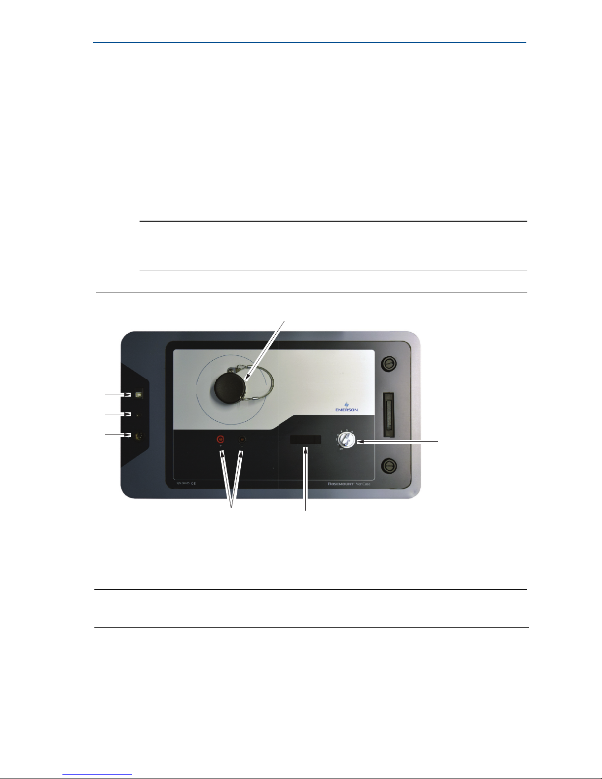
The picture below identifies the parts inside the case that the user should be
familiar with before performing verification.
Note
The Rosemount VeriCase does not have any hazardous approvals certifications and should
only be used outside of such classified areas.
Figure 1. Rosemount VeriCase
A
February 2017
G
F
E
B
A.Transmitter mount E. Power input
B. Terminal connections F. Ground connection
C. Cable switch G. USB cable connection
D. Temperature display
D
Contents
Rosemount VeriCase overview . . . . . . . . . . . . . . . . 2
Check Rosemount VeriCase and verification sheet 3
Performing a verification on a Rosemount 5300
transmitter . . . . . . . . . . . . . . . . . . . . . . . . . . . . . . . . . 4
Performing a verification on a Rosemount 3308
transmitter . . . . . . . . . . . . . . . . . . . . . . . . . . . . . . 6
Generating a report . . . . . . . . . . . . . . . . . . . . . . . 8
Appendix . . . . . . . . . . . . . . . . . . . . . . . . . . . . . . . . 9
C
2
Page 3

February 2017
Quick Start Guide
2.0 Check Rosemount VeriCase and verification
sheet
2.1 Check contents
Open the Rosemount VeriCase and check that it contains the following items;
USB stick containing
- User Instructions
-Microsoft
- Calibration certificate
- HART modem drivers
- Rosemount Radar Master (for Rosemount 5300 Level Transmitter)
- Rosemount Configuration Tool (for Rosemount 3308 Wireless Level
Tran smi tte r)
Printed calibration parameters
Printed certificate
110/220V Power Supply
12 VDC Power Cable
USB A-B cable
Two terminal connection cables with banana plugs and grippers
®
Excel® workbook
2.2 Check verification sheet
Open the Excel workbook found on the USB memory stick and check that the
following details in the workbook correspond to the printed certificate found
inside the Rosemount Vericase;
Serial number and calibration date
Cable lengths
Values for temperature correction table
2.3 Power-up the Rosemount VeriCase
The Rosemount VeriCase can be powered by either a 110V/220V power supply
or a 12VDC power adapter supplied with the Rosemount VeriCase. In order to
power-up the Rosemount VeriCase and connect to a transmitter head, follow
the steps below;
Connect the power cable
Screw the transmitter firmly onto the mount on the faceplate
Insert the terminal connectors in the '+' and '–' terminals on the faceplate and
attach the other ends to the terminals of the transmitter
Connect the USB A-B cable between your computer and the Rosemount
VeriCase.
In order to start the verification procedure the switch should be turned from
position '0' to position '1'.
3
Page 4

Quick Start Guide
February 2017
3.0 Performing a verification on a Rosemount 5300
transmitter
3.1 Before you start
Open Rosemount Radar Master and record the serial number and firmware
revision of the device to be tested in the verification data tab of the
workbook. This information can be found in the device properties window in
the 'device' menu in Rosemount Radar Master.
3.2 Verification procedure
Note
Inches or millimeters should be selected for measurement units (there is a possible
inaccuracy of 1.25mm (0,05-in.) when inches are used for the display).
Configure device for verification
1. Save a backup file of the current device (this will need to be reloaded once
the verification is complete) by selecting Device -> Save Config to File…
2. In the Ta nk window under the Setup menu, configure the following
parameters for the transmitter that will be tested:
-Probe type: User Defined
- Probe length: longest cable length +50cm (20-in)
-Probe Impedance: 100 Ω
- Reference Pulse Amplitude: 3000mV
Make sure that the below parameters are set with the following values
- Propagation Factor: 1,000
- Tank Connection Length: 0
- Remote housing: None
-Probe angle: 0
- Vapor DC: 1
- Measurement mode: Liquid product level, solid product level or
product level and interface level
4
Page 5

February 2017
Save these configuration changes and restart the device.
3.3 Verification test
1. Set the Cable Switch to position 1. Wait for the values to stabilize before
taking a reading from the Device Display window in Rosemount Radar Master.
Quick Start Guide
2. Record the distance value, internal temperature of transmitter and
Rosemount VeriCase temperature.
3. Repeat the procedure in 2 for all six cable lengths in the Rosemount VeriCase.
4. Once the verification is complete, restore the original configuration by
uploading the backup file to the transmitter. Select Device -> Upload Config
from File… and reload the file saved (see Configure device for verification ).
5. After the backup has been restored, disconnect power and communication
to the transmitter.
5
Page 6

Quick Start Guide
February 2017
4.0 Performing a verification on a Rosemount 3308
transmitter
4.1 Before you start
Record the serial number of the device from the nameplate located on top of
the transmitter. Open Radar Configuration Tools and record the software
revision of the device to be tested in the verification data tab of the workbook.
This information can be found in the setup window under the info tab.
4.2 Verification procedure
Note
Inches or millimeters should be selected for measurement units (there is a possible
inaccuracy of 1.25mm (0,05-in.) when inches are used for the display).
Configure device for verification
1. Save a memory map from the current device (this will need to be reloaded
once the verification is complete) by selecting Memory Map from the
left-hand menu. Select Receive. When the values have finished loading
select File and Save Memory.
Note
When reading a measurement value remember that the repeatability of a Rosemount
3308 is ± 2mm (0,08-in.)
2. In the Setup window under the Setup menu, configure the following
parameters for the transmitter that will be tested:
Probe type: User Defined
6
Page 7

February 2017
Probe length: longest cable length +50cm (20-in)
Probe Impedance: 100 Ω
Reference Pulse Amplitude: 30mV
Make sure that the below parameters are set with the following values
Propagation Factor: 1,000
Tank Connection Length: 0
Probe angle: 0
Vapor DC: 1
Measurement mode: Liquid product level or product level and interface
Quick Start Guide
level
- Save these configuration changes and restart the device.
4.3 Verification test
1. Set the Cable Switch to position 1. Open Monitor in the left-hand menu.
Select Product Distance and Electronics Temperature and press play. Wait
for the values to stabilize before taking a reading from the Device Display
window in Rosemount Radar Master.
2. Record the Product Distance value, Electronics Temperature and
Rosemount VeriCase temperature.
3. Repeat the procedure in 2 for all six cable lengths in the Rosemount VeriCase.
4. Once the verification is complete, restore the original configuration by
uploading the memory map to the transmitter. Select File from the top
menu and Open Memory Map. When the values have loaded select Send to
reload the configuration file saved (see Configure device for verification ).
7
Page 8

Quick Start Guide
February 2017
5. After the configuration has been restored, disconnect communication to the
transmitter.
5.0 Generating a report
Once testing is complete, a report can be generated from the Excel workbook. It
is possible to generate a verification report and/or a Q4 certificate by selecting
the corresponding generate report buttons located at the bottom of the
verification data tab and the Q4 data tab respectively. In order to generate a Q4
certificate the analog output of the transmitter under verification should be
tested at 4mA, 12mA and 20mA and the results saved in the Q4 data tab before
generating the certificate.
8
Page 9

February 2017
6.0 Appendix
6.1 FAQs
Q: Can verification of a FOUNDATION™ Fieldbus transmitter be performed using
the Rosemount VeriCase?
Quick Start Guide
A: Yes, but an external F
Explosion proof) will be required as a F
OUNDATION Fieldbus modem (and power supply if
OUNDATION Fieldbus modem is not built in
to the Rosemount VeriCase.
Q: What do I do if a device fails?
A: Check that the device is correctly configured and repeat the test. If the results
are the same, log a support request in the same way as you would with other
level instrumentation, providing all details of the testing, including results and
backup files.
Q: How do I know if a device has passed the test?
A: Refer to the Rosemount 5300 PDS for accuracy specifications. A device has
passed if the final result is inside the combined accuracy for the Rosemount 5300
and the Rosemount VeriCase as shown in the Excel workbook.
Q: What does the offset value in the results mean? Do I need to adjust anything
in the guided wave radar settings?
A: This is the offset generated from using the Rosemount VeriCase rather than a
probe. This is compensated for automatically and there is no need for manual
adjustments.
Q: Why is the transmitter rebooted every time I switch cable length?
A: This is so the measurement can be reset to lock on to a new value without
echo logic or filtering affecting the measurement.
Q: How often should Rosemount VeriCase be calibrated?
A: Once a year or if calibration seals have been broken.
Q: The calibration of the Rosemount VeriCase has expired. What do I do?
A: Every world area has an assigned administrator to coordinate recalibrations.
Contact your administrator for further instructions.
9
Page 10

Global Headquarters
Emerson Automation Solutions
6021 Innovation Blvd.
Shakopee, MN 55379, USA
+1 800 999 9307 or +1 952 906 8888
+1 952 949 7001
RFQ.RMD-RCC@Emerson.com
North America Regional Office
Emerson Automation Solutions
8200 Market Blvd.
Chanhassen, MN 55317, USA
+1 800 999 9307 or +1 952 906 8888
+1 952 949 7001
RMT-NA.RCCRFQ@Emerson.com
Latin America Regional Office
Emerson Automation Solutions
1300 Concord Terrace, Suite 400
Sunrise, FL 33323, USA
+1 954 846 5030
+1 954 846 5121
RFQ.RMD-RCC@Emerson.com
Europe Regional Office
Emerson Automation Solutions
Neuhofstrasse 19a P.O. Box 1046
CH 6340 Baar
Switzerland
+41 (0) 41 768 6111
+41 (0) 41 768 6300
RFQ.RMD-RCC@Emerson.com
*00825-0500-4530*
Quick Start Guide
00825-0500-4530, Rev AC
February 2017
Linkedin.com/company/Emerson-Automation-Solutions
Twitter.com/Rosemount_News
Facebook.com/Rosemount
Youtube.com/ user/RosemountMeasurement
Asia Pacific Regional Office
Emerson Automation Solutions
1 Pandan Crescent
Singapore 128461
+65 6777 8211
+65 6777 0947
Enquiries@AP.Emerson.com
Middle East and Africa Regional Office
Emerson Automation Solutions
Emerson FZE P.O. Box 17033
Jebel Ali Free Zone - South 2
Dubai, United Arab Emirates
+971 4 8118100
+971 4 8865465
RFQ.RMTMEA@Emerson.com
Google.com/+RosemountMeasurement
Standard Terms and Conditions of Sale can be found on the Ter ms
and Conditions of Sale page.
The Emerson logo is a trademark and service mark of Emerson
Electric Co.
Rosemount and Rosemount logotype are trademarks of Emerson.
HART is a registered trademark of the FieldComm Group.
Modbus is a registered trademark of Gould Inc.
FOUNDATION Fieldbus is a trademark of the FieldComm Group.
Excel and Microsoft are a registered trademarks of Microsoft
Corporation in the United States and other countries.
All other marks are the property of their respective owners.
© 2017 Emerson. All rights reserved.
 Loading...