

Page 1
Rosemount™ 3308 Series Wireless Guided Wave Radar, 3308A
Product Data Sheet
January 2018
00813-0100-4308, Rev DB
World’s first true wireless Guided Wave Radar based on field proven, market leading technologies
Accurate, direct level and interface measurements virtually unaffected by process conditions
Fast and simple commissioning with self-organizing wireless network, intuitive user interface and cut-to-fit
probes
Minimized maintenance with no wires, no moving parts, no re-calibration, long battery life and advanced
diagnostics for better process insight
Page 2
Rosemount 3308 Series
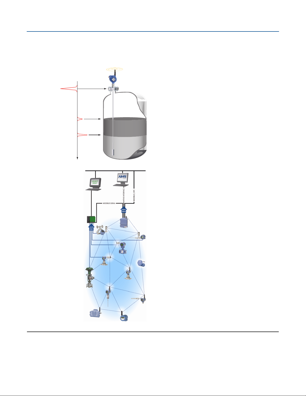
Product level
Interface level
Reference pulse
Introduction
January 2018
Guided wave radar
The Rosemount 3308 Series measurement is based on the Time
Domain Reflectometry (TDR) principle. Low power
nano-second-pulses are guided along a probe submerged in the
process media. When a pulse reaches the surface of the material
it is measuring, part of the energy is reflected back to the
transmitter, and the time difference between the generated and
reflected pulse is converted into a distance from which the total
level or interface level is calculated (see left).
The reflectivity of the product, its dielectric constant, is a key
parameter for measurement performance. A high dielectric
constant of the media gives better reflection and a longer
measuring range.
With innovative technologies inherited from other market
leading Rosemount guided wave radars, Rosemount 3308 Series
delivers reliable measurements without compromising a long
battery life.
Emerson™ Wireless
Emerson Wireless is a self-organizing network solution. Wireless
field instruments send data to a Gateway, directly or routed
through any of the wireless devices in the network. Multiple
communication paths are managed and analyzed in parallel to
assure optimal communication and sustained network reliability
even if obstructions are introduced.
Gateways interface with existing host systems using industry
standard protocols, and native integration into DeltaV
Ovation
Interference from other radios, Wi-Fi
avoided through Time Synchronized Channel Hopping and
Direct Sequence Spread Spectrum (DSSS). Also, a layered
security implementing industry standard Encryption,
Authentication, Verification, Anti-Jamming, and Key
Management ensures that data transmissions are secure and
received only by the Gateway.
The Rosemount 3308 Series is a member of the Emerson
Wireless portfolio, whose wireless network experience totals
billions of operating hours, hundreds of thousands field devices,
and tens of thousands of networks around the world.
™
is transparent and seamless.
®
, and EMC sources is
™
and
Contents
Ordering Information . . . . . . . . . . . . . . . . . . . . . . . . . . . . . 4
Specifications . . . . . . . . . . . . . . . . . . . . . . . . . . . . . . . . . . . 14
2
Product Certifications . . . . . . . . . . . . . . . . . . . . . . . . . . . .29
Dimensional Drawings . . . . . . . . . . . . . . . . . . . . . . . . . . . .32
Emerson.com/Rosemount
Page 3
January 2018
Oil
Oil
Water
Rosemount 3308 Series
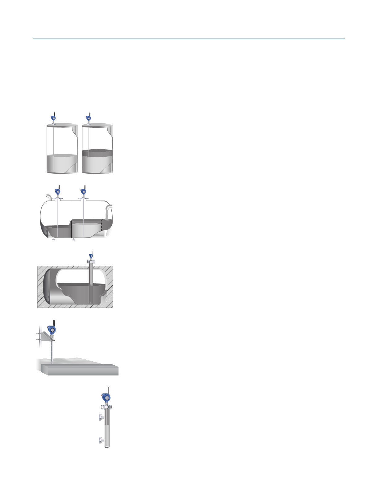
Application examples
The Rosemount 3308 Series Transmitter is suited for aggregate (total) level measurements on a wide range of liquids, semi-liquids,
and liquid/liquid interfaces.
The quick and easy installation of true wireless transmitters makes the Rosemount 3308 Series an ideal solution to automate
measurements in remote locations or where existing wiring is limited. Moreover, the reliable and accurate nature of guided wave
radar technology offers a versatile solution that is virtually unaffected by process conditions such as temperature, pressure, vapor gas
mixtures, density, turbulence, bubbling/boiling, varying dielectric media, pH, and viscosity.
Storage and buffer tanks
The Rosemount 3308 Series Transmitter is ideal for storage or buffer
tanks for almost any liquid, such as oil, gas condensate, water, or
chemicals.
Low pressure separators
The Rosemount 3308 Series Transmitter can measure both level and
interface level, such as for separator applications.
Waste tanks and sump pits
The Rosemount 3308 Series Transmitter is also a good choice for
waste tanks and underground tanks, such as sump pits.
Open applications—ponds, basins, sumps
The Rosemount 3308 Series Transmitter can be installed in open air
to measure liquids not contained in a tank.
Chamber applications
The Rosemount 3308 Series Transmitter is a good choice for both
chamber and pipe installations.
Emerson.com/Rosemount
3
Page 4
Rosemount 3308 Series
January 2018
Ordering Information
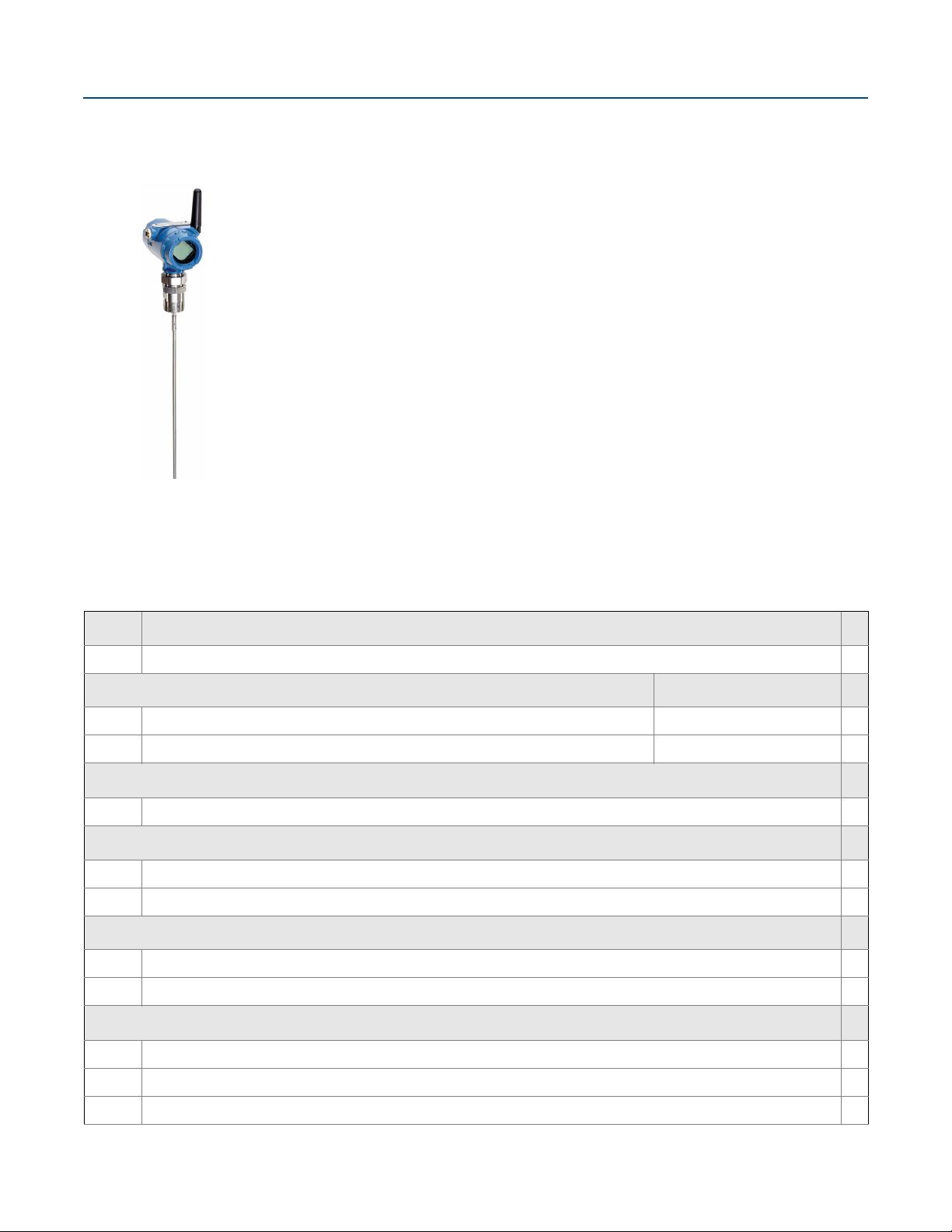
Rosemount 3308 Series Guided Wave Radar Level Transmitters are versatile and easy-to-use with
field proven, market leading technologies. Characteristics include:
• Intrinsically Safe
• Long battery life
®
• IEC 62591 (WirelessHART
• Compatible with AMS Device Manager and AMS Wireless Configurator packages for easy
commissioning and troubleshooting
Additional Information
Specifications: page 14
Interface Measurement: page 21
Mechanical Considerations: page 26
Chamber/Pipe Installations: page 27
Certifications: page 29
Dimensional Drawings: page 32
Specification and selection of product materials, options, or components must be made by the purchaser of the equipment.
See page 23 for more information on Material Selection.
) Communication
Table 1. Rosemount 3308 Series Level and/or Interface Measurements in Liquids Ordering Information
The starred offerings (★) represent the most common options and should be selected for best delivery. The non-starred offerings are subject
to additional delivery lead time.
Model Product description
3308A Guided Wave Radar Level Transmitter
★
Profile Reference accuracy
(1)(2)
U
S Standard ±0.25 in. (±6 mm)
High Performance ±0.12 in. (±3 mm)
★
★
Signal output (see page 19 for details)
X Wireless
★
Measurement type (see page 21)
2 Level and Interface Transmitter
1 Level or Interface Transmitter (Interface available for fully submerged probe)
★
Housing
D1 Wireless Dual Compartment Housing, Aluminum (with plugged ½-14 NPT conduits)
E1 Wireless Dual Compartment Housing, Stainless steel (with plugged ½-14 NPT conduits)
★
★
Hazardous locations certifications (see page 29-31)
I1 ATEX Intrinsic Safety
I2 INMETRO Intrinsic Safety
I3 NEPSI Intrinsic Safety
4
★
★
★
Emerson.com/Rosemount
Page 5

January 2018
Rosemount 3308 Series
Table 1. Rosemount 3308 Series Level and/or Interface Measurements in Liquids Ordering Information
The starred offerings (★) represent the most common options and should be selected for best delivery. The non-starred offerings are subject
to additional delivery lead time.
I4 TIIS Intrinsic Safety
★
I5 FM Intrinsically Safe
I6 Canadian Intrinsically Safe
I7 IECEx Intrinsic Safety
IM Technical Regulations Customs Union (EAC) Intrinsic Safety
KD ATEX and Canadian Intrinsic Safety
KE FM and Canadian Intrinsically Safe
KF ATEX and FM Intrinsic Safety
NA No Hazardous Locations Certifications
Operating temperature and pressure (see page 20)
S - 15 psig (-1bar) to 580 psig (40 bar) @ 302 °F (150 °C)
Material of construction; process connection/probe Probe type
1 316L SST (EN 1.4404) All
2 Alloy C-276 (UNS N10276). With plate design if flanged version. 3A, 3B, 4A, 4B, and 5A
3 Alloy 400 (UNS N04400). With plate design if flanged version. 3A, 3B, 4A, 4B, and 5A
7 PTFE covered probe and flange. With plate design. 4A and 5A
8 PTFE covered probe 4A and 5A
★
★
★
★
★
★
H Alloy C-276 (UNS N10276) process connection, flange, and probe 3A, 3B, 4A, 4B, and 5A
D Duplex 2205 (UNS S31803) process connection, flange, and probe 4B and 5A
Sealing O-ring material (see page 20)
V Viton® Fluoroelastomer
E Ethylene Propylene (EPDM)
K Kalrez® 6375 Perfluoroelastomer
B Nitrile Butadiene (NBR)
Process connection size (see Table 2 and Table 3 on page 10 for availability) Process connection type
5 1½-in. Thread/Tri Clamp
2 2-in./DN50/50A NPT Thread/Flange/Tri Clamp
3 3-in./DN80/80A Flange/Tri Clamp
4 4-in./DN100/100A Flange/Tri Clamp
P Proprietary Flanges Proprietary Flange
1 1-in. Thread
6 6-in./DN150/150A Flange
8 8-in./DN200/200A Flange
★
★
★
★
★
★
★
★
★
Emerson.com/Rosemount
5
Page 6
Rosemount 3308 Series
January 2018
Table 1. Rosemount 3308 Series Level and/or Interface Measurements in Liquids Ordering Information
The starred offerings (★) represent the most common options and should be selected for best delivery. The non-starred offerings are subject
to additional delivery lead time.
Process connection rating (see Tab le 2 and Table 3 on page 10 for availability)
NN For use with non-flange process connection type
ASME rating
AA ASME B16.5 Class 150 Flange
AB ASME B16.5 Class 300 Flange
EN rating
DA EN1092-1 PN16 Flange
DB EN1092-1 PN40 Flange
JIS rating
JA JIS B2220 10K Flange
JB JIS B2220 20K Flange
Proprietary
PF Proprietary Flange
Process connection type (see Tabl e 2 and Table 3 on page 10 for availability)
Thread
N NPT thread
G BSPP (G) thread
★
★
★
★
★
★
★
★
★
★
Flange faces
F Flat Face (FF) Flange, available for EN flanges
R Raised Face (RF) Flange, available for ASME and JIS flanges
Proprietary flanges (see page 39 for dimensions)
M Masoneilan™-Proprietary, 316 SST Torque Tube Flange, 316L
P Fisher™-Proprietary, 316 SST, (for 249B and 259B cages) Torque Tube Flange, 316L
Q Fisher-Proprietary, 316 SST, (for 249C cages) Torque Tube Flange, 316L
Tri Cla mp
C Tri Clamp
Probe type Process connection type Probe lengths
3B
Coaxial, perforated. For level and interface
measurement.
Flange/1-, 1½-, 2-in. Thread
4A Rigid Single Lead (d=0.3"/8 mm) Flange/1-, 1½-, 2-in. Thread/Tri Clamp
4B Rigid Single Lead (d=0.5"/13 mm) Flange/1½-, 2-in. Thread/Tri Clamp
5A
Flexible Single Lead (d=0.16"/4 mm).
Refer to page 8 to specify weight or chuck.
Flange/1-, 1½-, 2-in. Thread/Tri Clamp
Min.:1 ft. 4 in. (0.4 m)
Max.: 19 ft. 8 in. (6 m)
Min.:1 ft. 4 in. (0.4 m)
Max.: 9 ft. 10 in. (3 m)
Min.:1 ft. 4 in. (0.4 m)
Max.: 19 ft. 8 in. (6 m)
Min.:3 ft. 4 in. (1 m)
Max.: 55 ft. 9 in. (17 m)
★
★
★
★
★
★
(3)
★
★
(3)
★
6
Emerson.com/Rosemount
Page 7
January 2018
Rosemount 3308 Series
Table 1. Rosemount 3308 Series Level and/or Interface Measurements in Liquids Ordering Information
The starred offerings (★) represent the most common options and should be selected for best delivery. The non-starred offerings are subject
to additional delivery lead time.
2A Flexible Twin Lead with weight Flange/1½-, 2-in. Thread
Min.:3 ft. 4 in. (1 m)
Max.: 55 ft. 9 in. (17 m)
(4)
3A
Coaxial (for level measurement) Flange/1-, 1½-, 2-in. Thread
4S Segmented Rigid Single Lead (d=0.5"/13 mm) Flange/1½-, 2-in. Thread
Min.:1 ft. 4 in. (0.4 m)
Max.: 19 ft. 8 in. (6 m)
Min.: 1 ft. 4 in. (0.4 m)
Max: 32 ft. 9 in. (10 m)
Probe length units (see page 23 for total probe length)
E English (feet, inches)
M Metric (meters, centimeters)
Probe length (feet/meters)
XXX 0-55 feet or 0-17 meters
Probe length (inches/centimeters)
XX 0-11 inches or 0-99 Centimeters
Update rate, operating frequency and protocol
WA3 User Configurable Update Rate, 2.4 GHz, IEC 62591 (WirelessHART)
Omnidirectional wireless antenna and SmartPower™ solutions (see page 19 for functional specification)
WK1 External Antenna, Adapter for Intrinsically Safe Black Power Module (Power Module Sold Separately)
WN1
High Gain, Remote Antenna (see page 38 for dimensions), Adapter for Intrinsically Safe Black Power Module (Power
Module Sold Separately)
★
★
★
★
★
★
★
Note: Black Power Module must be shipped separately; order Model 701PBKKF (part number 00753-9220-0001).
Options (include with selected model number)
Display
M5 LCD Display (see page 19)
Hydrostatic testing
P1 Hydrostatic Testing, including certificate
Factory configuration
C1 Factory Configuration per Configuration Data Sheet
Special quality assurance
Q4 Calibration Data Certificate
Material traceability certification
(5)
Q8
Material Traceability Certification per EN 10204 3.1
★
★
★
★
★
Emerson.com/Rosemount
7
Page 8
Rosemount 3308 Series
January 2018
Table 1. Rosemount 3308 Series Level and/or Interface Measurements in Liquids Ordering Information
The starred offerings (★) represent the most common options and should be selected for best delivery. The non-starred offerings are subject
to additional delivery lead time.
Welding procedure qualification/specification
Q66 Welding Procedure Qualification Record Documentation
Q67 Welder Performance Qualification Record
Q68 Welding Procedure Specification
Special certifications
QG GOST Certification
Materials certification
(6)
Q15
NACE® material recommendation per NACE MR0175/ISO 15156
Installation options
LS Long Stud for Flexible Single Lead Probes, 25 cm (10 in.) (for use in tall nozzles)
BR Mounting Bracket for 1½-in. NPT Process Connection (see page 37)
Weight and anchoring options for flexible single probes (see page 32 for dimensions)
W1 Small Weight (for narrow tank openings less than 2 in. (50 mm)) (Required for PTFE covered probes)
W3 Heavy weight (for most applications)
W4 Chuck (to tie probe end to tank bottom)
W2 Short weight (when measuring close to the probe end)
Weight assembly options for flexible single probes
WU Weight or chuck not mounted on the probe
Extended product warranty
WR3 3-year limited warranty
WR5 5-year limited warranty
Plantweb™ diagnostic functionality
★
★
★
★
★
★
★
★
DA1 HART® Diagnostics (see page 19)
Centering disc (see page 28 for dimensions and size recommendation)
(8)
S2
S3
S4
2-in. Centering disc
(8)
3-in. Centering disc
(8)
4-in. Centering disc
P2 2-in. Centering disc PTFE
P3 3-in. Centering disc PTFE
P4 4-in. Centering disc PTFE
(8)
S6
S8
6-in. Centering disc
(8)
8-in. Centering disc
8
★
(7)
★
★
★
★
★
★
Emerson.com/Rosemount
Page 9
January 2018
Rosemount 3308 Series
Table 1. Rosemount 3308 Series Level and/or Interface Measurements in Liquids Ordering Information
The starred offerings (★) represent the most common options and should be selected for best delivery. The non-starred offerings are subject
to additional delivery lead time.
P6 6-in. Centering disc PTFE
P8 8-in. Centering disc PTFE
Assemble/consolidate to chamber (see page 27)
XC Consolidate to Chamber
★
Engineered solutions (see page 26)
Pxxxx Engineered Solutions beyond standard model codes. (Consult factory for details)
1. The Rosemount 3308A with profile code U has two performance modes: Standard and High Performance (default). The performance mode may be reconfigured in
field.
2. Available with hazardous locations certifications I1, I5, I6, and I7.
3. Minimum probe length is 4 ft. 11 in. (1.5 m) for PTFE covered probes (Material of Construction codes 7 and 8).
4. Requires model 3308Axx1.
5. Certificate includes all metallic pressure retaining wetted parts.
6. Available for Probe Type 3A, 3B, 4A, 4B, 4S, and PTFE-coated 5A.
7. Available for SST, Alloy C-276, Alloy 400, and Duplex 2205 probes, type 2A, 4A, 4B, 4S, and 5A. Not available with PTFE covered probes (Material of Construction
codes 7 and 8).
8. Centering disc in same material as probe material of construction.
Emerson.com/Rosemount
9
Page 10
Rosemount 3308 Series
January 2018
Table 2. Availability of Process Connections - Material of Construction Codes 1, 2, 3, 7, and 8
(Type vs. Size and Rating)
Process connection size Process connection rating
Thread/Tri Clamp ASME B16.5 flanges EN1092-1 flanges JIS B2220 flanges Proprietary
Class 150 Class 300 PN16 PN40 10K 20K
1-in. G
(2)
1½-in. C
2-in./DN50/50A C
, N
(2)
3-in./DN80/80A C
4-in./DN100/100A C
, N
(3)
, N
(2)
(2)
, G
(2)
(3)
N/A N/A N/A N/A N/A N/A N/A
N/A N/A N/A N/A N/A N/A N/A
RRF FRR N/A
RRF FRR N/A
RRF FRR N/A
(2)
(2)
6-in./DN150/150A N/A R R F F R R N/A
8-in./DN200/200A N/A R R F F R R N/A
Proprietary flanges N/A N/A N/A N/A N/A N/A N/A M, P, Q
1. Only available with material of construction codes 1, 7, and 8.
2. Only available with material of construction codes 1 and 8.
3. Only available with material of construction codes 1, 2, 3, and 8.
C = Tri Clamp (process connection type code C)
F = Flat Face (process connect ion type code F)
G = BSPP (G) thread (process connection type code G)
M = Maso neilan (pro cess connec tion typ e code M)
N = NPT thread (process connection type code N)
P = Fisher 249B/259B (process connection type code P)
Q = Fisher 249C (process connection type code Q)
R = Raised Face (process conn ection type code R)
flanges
(1)
Table 3. Availability of Process Connections - Material of Construction Codes H and D (Type vs. Size and Rating)
Process connection size Process connection rating
Thread/Tri Clamp ASME B16.5 flanges EN1092-1 flanges JIS B2220 flanges Proprietary
Class 150 Class 300 PN16 PN40 10K 20K
1-in. N/A N/A N/A N/A N/A N/A N/A N/A
1½-in. G, N N/A N/A N/A N/A N/A N/A N/A
2-in./DN50/50A N/A R R N/A N/A N/A N/A N/A
3-in./DN80/80A N/A R R N/A N/A N/A N/A N/A
4-in./DN100/100A N/A R R N/A N/A N/A N/A N/A
6-in./DN150/150A N/A R
(1)
N/A N/A N/A N/A N/A N/A
8-in./DN200/200A N/A N/A N/A N/A N/A N/A N/A N/A
Proprietary flanges N/A N/A N/A N/A N/A N/A N/A N/A
1. Only available with material of construction code H.
G = BSPP (G) thread (process connection type code G)
N = NPT thread (process connection type code N)
R = Raised Face (process conn ection type code R)
flanges
10
Emerson.com/Rosemount
Page 11

January 2018
Rosemount 3308 Series
Table 4. Accessories Ordering Information
The starred offerings (★) represent the most common options and should be selected for best delivery. The non-starred offerings are subject
to additional delivery lead time.
Centering discs for rigid single lead probe (d=0.3"/8 mm)
(1)(2)
Outer diameter
03300-1655-0001 Kit, 2-in. Centering Disc, SST 1.8 in. (45 mm)
03300-1655-0006 Kit, 2-in. Centering Disc, PTFE 1.8 in. (45 mm)
03300-1655-0002 Kit, 3-in. Centering Disc, SST 2.7 in. (68 mm)
03300-1655-0007 Kit, 3-in. Centering Disc, PTFE 2.7 in. (68 mm)
03300-1655-0003 Kit, 4-in. Centering Disc, SST 3.6 in. (92 mm)
03300-1655-0008 Kit, 4-in. Centering Disc, PTFE 3.6 in. (92 mm)
03300-1655-0004 Kit, 6-in. Centering Disc, SST 5.55 in. (141 mm)
03300-1655-0009 Kit, 6-in. Centering Disc, PTFE 5.55 in. (141 mm)
03300-1655-0005 Kit, 8-in. Centering Disc, SST 7.40 in. (188 mm)
03300-1655-0010 Kit, 8-in. Centering Disc, PTFE 7.40 in. (188 mm)
Centering discs for rigid single lead probe (d=0.5"/13 mm)
(1)(2)
Outer diameter
03300-1655-0301 Kit, 2-in. Centering Disc, SST 1.8 in. (45 mm)
03300-1655-0306 Kit, 2-in. Centering Disc, PTFE 1.8 in. (45 mm)
03300-1655-0302 Kit, 3-in. Centering Disc, SST 2.7 in. (68 mm)
03300-1655-0307 Kit, 3-in. Centering Disc, PTFE 2.7 in. (68 mm)
03300-1655-0303 Kit, 4-in. Centering Disc, SST 3.6 in. (92 mm)
★
★
★
★
★
★
★
★
★
★
★
03300-1655-0308 Kit, 4-in. Centering Disc, PTFE 3.6 in. (92 mm)
03300-1655-0304 Kit, 6-in. Centering Disc, SST 5.55 in. (141 mm)
03300-1655-0309 Kit, 6-in. Centering Disc, PTFE 5.55 in. (141 mm)
03300-1655-0305 Kit, 8-in. Centering Disc, SST 7.40 in. (188 mm)
03300-1655-0310 Kit, 8-in. Centering Disc, PTFE 7.40 in. (188 mm)
Centering discs for flexible single/twin lead probes
(1)(2)
Outer diameter
03300-1655-1001 Kit, 2-in. Centering disc, SST 1.8 in. (45 mm)
03300-1655-1006 Kit, 2-in. Centering disc, PTFE 1.8 in. (45 mm)
03300-1655-1002 Kit, 3-in. Centering disc, SST 2.7 in. (68 mm)
03300-1655-1007 Kit, 3-in. Centering disc, PTFE 2.7 in. (68 mm)
03300-1655-1003 Kit, 4-in. Centering disc, SST 3.6 in. (92 mm)
03300-1655-1008 Kit, 4-in. Centering disc, PTFE 3.6 in. (92 mm)
03300-1655-1004 Kit, 6-in. Centering disc, SST 5.55 in. (141 mm)
03300-1655-1009 Kit, 6-in. Centering disc, PTFE 5.55 in. (141 mm)
03300-1655-1005 Kit, 8-in. Centering disc, SST, 7.40 in. (188 mm)
03300-1655-1010 Kit, 8-in. Centering disc, PTFE 7.40 in. (188 mm)
★
★
★
★
★
★
★
Emerson.com/Rosemount
11
Page 12

Rosemount 3308 Series
January 2018
Table 4. Accessories Ordering Information
The starred offerings (★) represent the most common options and should be selected for best delivery. The non-starred offerings are subject
to additional delivery lead time.
Centering discs for mounting between segments (probe type 4S only) Outer diameter
03300-1656-1002 2-in. Centering Disc (1 pc), PTFE, Segmented Rigid Single Lead 1.8 in. (45 mm)
03300-1656-1003 3-in. Centering Disc (1 pc), PTFE, Segmented Rigid Single Lead 2.7 in. (68 mm)
03300-1656-1004 4-in. Centering Disc (1 pc), PTFE, Segmented Rigid Single Lead 3.6 in. (92 mm)
03300-1656-1006 6-in. Centering Disc (1 pc), PTFE, Segmented Rigid Single Lead 5.55 in. (141 mm)
03300-1656-1008 8-in. Centering Disc (1 pc), PTFE, Segmented Rigid Single Lead 7.40 in. (188 mm)
03300-1656-3002 2-in. Centering Disc (3 pcs), PTFE, Segmented Rigid Single Lead 1.8 in. (45 mm)
03300-1656-3003 3-in. Centering Disc (3 pcs), PTFE, Segmented Rigid Single Lead 2.7 in. (68 mm)
03300-1656-3004 4-in. Centering Disc (3 pcs), PTFE, Segmented Rigid Single Lead 3.6 in. (92 mm)
03300-1656-3006 6-in. Centering Disc (3 pcs), PTFE, Segmented Rigid Single Lead 5.55 in. (141 mm)
03300-1656-3008 8-in. Centering Disc (3 pcs), PTFE, Segmented Rigid Single Lead 7.40 in. (188 mm)
03300-1656-5002 2-in. Centering Disc (5 pcs), PTFE, Segmented Rigid Single Lead 1.8 in. (45 mm)
03300-1656-5003 3-in. Centering Disc (5 pcs), PTFE, Segmented Rigid Single Lead 2.7 in. (68 mm)
03300-1656-5004 4-in. Centering Disc (5 pcs), PTFE, Segmented Rigid Single Lead 3.6 in. (92 mm)
03300-1656-5006 6-in. Centering Disc (5 pcs), PTFE, Segmented Rigid Single Lead 5.55 in. (141 mm)
03300-1656-5008 8-in. Centering Disc (5 pcs), PTFE, Segmented Rigid Single Lead 7.40 in. (188 mm)
Segmented rigid single lead probe spare part kit
03300-0050-0001 15.2-in./385 mm Segment for Top connection (1 pc)
03300-0050-0002 31.5-in./800 mm Segment (1 pc)
03300-0050-0003 31.5-in./800 mm Segment (3 pcs)
03300-0050-0004 31.5-in./800 mm Segment (5 pcs)
03300-0050-0005 31.5-in./800 mm Segment (12 pcs)
Vented flanges
03300-1812-0092 Fisher 249B/259B
03300-1812-0093 Fisher 249C
03300-1812-0091 Masoneilan
(3)
(4)
Flushing connection rings
DP0002-2111-S6 2-in. ANSI, ¼-in. NPT connection
DP0002-3111-S6 3-in. ANSI, ¼-in. NPT connection
DP0002-4111-S6 4-in. ANSI, ¼-in. NPT connection
DP0002-5111-S6 DN50, ¼-in. NPT. connection
DP0002-8111-S6 DN80, ¼-in. NPT. connection
12
Emerson.com/Rosemount
Page 13

January 2018
Rosemount 3308 Series
Table 4. Accessories Ordering Information
The starred offerings (★) represent the most common options and should be selected for best delivery. The non-starred offerings are subject
to additional delivery lead time.
Other
03300-7004-0001 MACTek® VIATOR® HART Modem and cables (RS232 connection)
03300-7004-0002 MACTek VIATOR HART Modem and cables (USB connection)
1. If a centering disc is required for a flanged probe, the centering disc can be ordered with options Sx or Px on page 8 in the model code. If a centering disc is required
for a th read ed co nne cti on o r as a spar e pa rt, it s houl d be orde red usin g th e ite m num ber s li sted in t his t abl e. Ref er to Tab le 20 for centering disc size recommendation
for different pipe schedules.
2. To order a centering disc in a different material, consult the factory.
3. 1½-in. NPT threaded connection is required.
4. For pressure and temperature rating, see “Fisher and Masoneilan” on page 20.
★
★
Emerson.com/Rosemount
13
Page 14

Rosemount 3308 Series
00
±0.25 in.
(6 mm)
±0.98 in.
(25 mm)
33 ft. (10 m)
56 ft. (17 m)
Accuracy
Measuring distance
Specifications
January 2018
Performance specifications
General
Reference conditions
Probe: Flexible single lead
Vessel: 4-in. pipe
Measurement target: Water
Temperature: 68 to 77 °F (20 to 25 °C)
Relative humidity: 30-80%
Reference accuracy
High performance (profile code U):
±0.12 in. (±3 mm), when distance < 33 ft. (10 m)
±0.03% of measured distance, when distance > 33 ft. (10 m)
Standard (profile code S):
Ambient temperature effect
High performance (profile code U): ±0.08 in. (±2 mm)/10 K
Standard (profile code S): < 0.1% of measured distance per 10 K
Electromagnetic interference effect
External antenna (WK1 option): < ±0.25 in. (±6 mm)
Remote (WN1 option): < ±0.2 in. (±5 mm)
Power module battery life
High performance: 5 years at one minute update rate
Standard: 9 years at one minute update rate
(1)
(2)
(3)
Electromagnetic compatibility
Meets EN 61326-1:2013, EN 61326-2-3:2013, and
NE21:2012 if installed in metallic vessels or still pipes.
For optimal single lead probe performance in non-metallic
tanks, the probe must be mounted with a metal flange, or
screwed in to a metal sheet (d > 14 in./350 mm) if a threaded
version is used. See page 26 for more information.
Pressure Equipment Directive (PED)
Complies with 2014/68/EU article 4.3
Radio approvals
Radio Equipment Directive (RED) 2014/53/EU
Part 15 of the FCC Rules
Industry Canada RSS 211
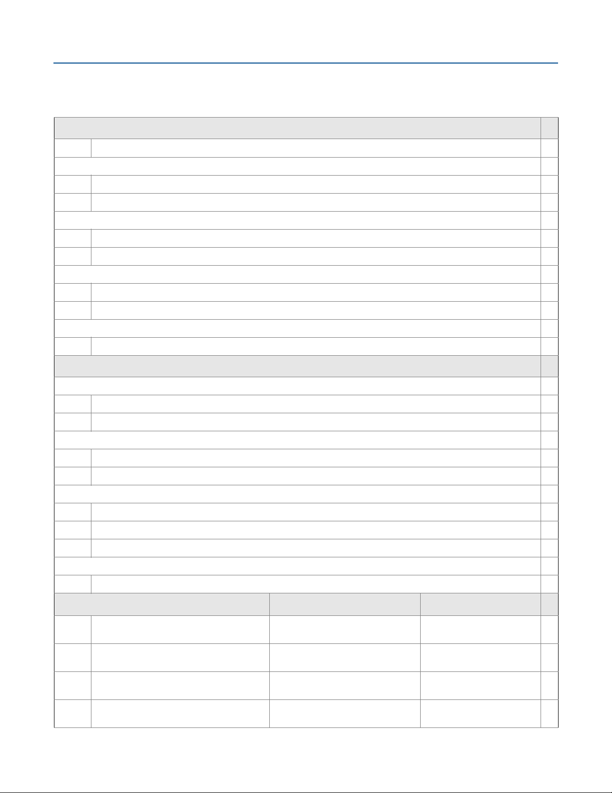
Interface measurement range
The maximum allowable upper product thickness/measuring
range is primarily determined by the dielectric constants of the
two liquids.
Typical applications include interfaces between oil/oil-like and
water/water-like liquids, with a low (<3) dielectric constant for
the upper product and a high (>20) dielectric constant for the
lower product. For such applications, the maximum measuring
range is limited by the length of the coaxial and rigid single lead
probes.
For flexible probes, the maximum measuring range is reduced
by the maximum upper product thickness, according to the
diagram below. However, characteristics may vary between the
different applications.
Environment
Vibration resistance
No effect when tested per the requirements of IEC60770-1
(1999): High Vibration Level - field or pipeline (10-60 Hz 0.21
mm displacement peak amplitude / 60-2000 Hz 3g).
1. Refer to the IEC 60770-1 standard for a definition of radar specific
performance parameters and if applicable corresponding test procedure.
2. Deviation through electromagnetic interference according to EN 61326.
3. Reference conditions are 70 °F (21 °C), and routing data for three
additional network devices.
14
Emerson.com/Rosemount
Page 15

January 2018
1
0
6.6 (2)
13.1 (4)
19.7 (6)
26.2 (8)
32.8 (10)
39.4 (12)
243
567
8910
11
80
80
40
20
10
10
Upper product dielectric constant
Maximum upper product thickness, ft. (m)
Lower product
dielectric constant
Example: With an upper product
dielectric constant of 2, and a
lower product dielectric constant
of 20, the maximum upper product
thickness is 25 ft. (7 m).
25 ft.
(7 m)
DC 2
DC 20
Figure 1. Maximum upper product thickness for
flexible probes
Rosemount 3308 Series
Table 5. Measuring Range and Minimum Dielectric Constant
Probe type Maximum measuring range Minimum dielectric constant
Flexible single lead 55.8 ft. (17 m)
Rigid single lead probe (0.3-in./8 mm) 9.8 ft. (3 m) 2.0
Rigid single lead probe (0.5-in./13 mm) 19.7 ft. (6 m) 2.0
Segmented rigid single lead 32.8 ft. (10 m) 2.0
Flexible twin lead 55.8 ft. (17 m)
Coaxial 19.7 ft. (6 m) 2.0
1. Minimum Dielectric Constant may be lower than 2.0 if one or mor e of the following conditions apply:
- Probe is installed in stilling well or chamber.
- Maximum measuring range is not utilized.
- Noise Threshold is manually adjusted to a lower level.
2. For temperatures above 140 °F (60 °C) manual adjustment of noise threshold may be required for products with low dielectric constant at or close to maximum
measuring range.
Table 6. Maximum Recommended Viscosity and Contamination/Build-up
2.0, when distance < 32.8 ft. (10 m)
10, when distance > 32.8 ft. (10 m)
2.0, when distance < 32.8 ft. (10 m)
10, when distance > 32.8 ft. (10 m)
Probe type Maximum viscosity Contamination/build-up
Single lead 8000 cP
Twin lead 1500 cP Thin build-up allowed, but no bridging
Coaxial 500 cP Not recommended
1. Consult your local Emerson representative in the case of agitation/turbulence and high viscous products.
2. For viscous or sticky applications, it is not recommended to use centering discs mounted along the probe.
Emerson.com/Rosemount
(1)(2)
Build-up allowed
(1)(2)
15
Page 16

Rosemount 3308 Series
Note
Measurements may not be possible in the Blind Zones, and
measurements close to the Blind Zones will have reduced
accuracy. Therefore, the alarm points should be configured
outside these zones.
Upper Blind Zone
Lower Blind Zone
Reduced accuracy
Reduced accuracy
±0.12 in.
(3 mm)
3.5 in. (9 cm)
14.6 in. (37 cm)
±1.18 in.
(30 mm)
±0.12 in.
(3 mm)
13.0 in. (33 cm)
±1.18 in.
(30 mm)
5.9 in. (15 cm)
4.3 in. (11 cm)
0.4 in. (1 cm)
8.7 in.
(22 cm)
2 in. (5 cm)
4.3 in.
(11 cm)
3.2 in. (8 cm)
3.2 in. (8 cm)
±0.25 in.
(6 mm)
±1.18 in.
(30 mm)
3.2 in. (8 cm)
9.8 in. (25 cm)
±0.25 in.
(6 mm)
±1.18 in.
(30 mm)
10.6 in. (27 cm)
5.1 in. (13 cm)
Accuracy
Water (DC = 80) Oil (DC = 2.2)
Blind Zone
Accuracy Accurac y
Standard (profile code S)
Water (DC = 80) Oil (DC = 2.2)
High performance (profile code U)
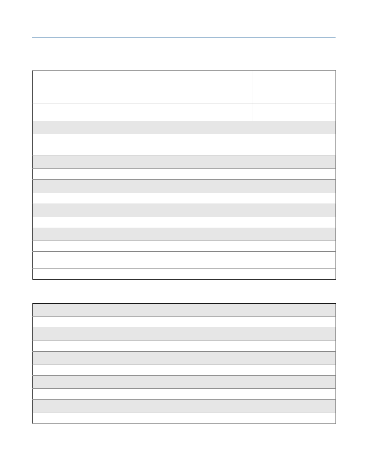
Accuracy over measuring range
The measuring range depends on probe type, dielectric
constant of the product and installation environment, and is
limited by the Blind Zones at the very top and bottom of the
probe. In the Blind Zones, the accuracy exceeds ±1.18 in. (30
mm), and measurements may not be possible. Measurements
close to the Blind Zones will have reduced accuracy.
The following conditions will impact the Blind Zones:
If the single lead probes or twin probes are installed in a
nozzle, the nozzle height shall be added to the specified
Upper Blind Zone.
The measuring range for the PTFE covered flexible single lead
probe includes the weight when measuring on a high
dielectric media.
Figure 2, Figure 3, Figure 4, and Figure 5 illustrate the accuracy
over measuring range at reference condition using the Trim Near
Zone function, with alternating probe types and varying
dielectric constant of the product.
January 2018
Figure 2. Accuracy over Measuring Range for Flexible Single Lead Probe
16
Emerson.com/Rosemount
Page 17

January 2018
3.5 in. (9 cm)
1.2 in. (3 cm)
3.9 in. (10 cm)
18.9 in. (48 cm)
±0.12 in.
(3 mm)
±1.18 in.
(30 mm)
3.9 in. (10 cm)
12.2 in. (31 cm)
0.8 in. (2 cm)
±0.12 in.
(3 mm)
±1.18 in.
(30 mm)
5.1 in.
(13 cm)
4.3 in. (11 cm)
2 in. (5 cm)
4.3 in.
(11 cm)
±0.25 in.
(6 mm)
±1.18 in.
(30 mm)
3.2 in. (8 cm)
9.8 in. (25 cm)
±0.25 in.
(6 mm)
±1.18 in.
(30 mm)
10.6 in. (27 cm)
5.1 in. (13 cm)
Accuracy
Water (DC = 80) Oil (DC = 2.2)
Blind Zone
Accuracy Accurac y
Standard (profile code S)
Water (DC = 80) Oil (DC = 2.2)
High performance (profile code U)
0.4 in. (1 cm)
3.5 in. (9 cm)
2 in. (5 cm)
2.8 in. (7 cm)
0.4 in. (1 cm)
7.9 in. (20 cm)
5.9 in. (15 cm)
9.5 in. (24 cm)
7.9 in.
(20 cm)
3.2 in. (8 cm)
7.9 in. (20 cm)
3.9 in. (10 cm)
12.6 in. (32 cm)
±0.12 in.
(3 mm)
±1.18 in.
(30 mm)
±0.12 in.
(3 mm)
±1.18 in.
(30 mm)
±0.25 in.
(6 mm)
±1.18 in.
(30 mm)
3.2 in. (8 cm)
7.9 in. (20 cm)
±0.25 in.
(6 mm)
±1.18 in.
(30 mm)
Accuracy
Water (DC = 80) Oil (DC = 2.2)
Blind Zone
Accuracy Accurac y
Standard (profile code S)
Water (DC = 80) Oil (DC = 2.2)
High performance (profile code U)
Rosemount 3308 Series
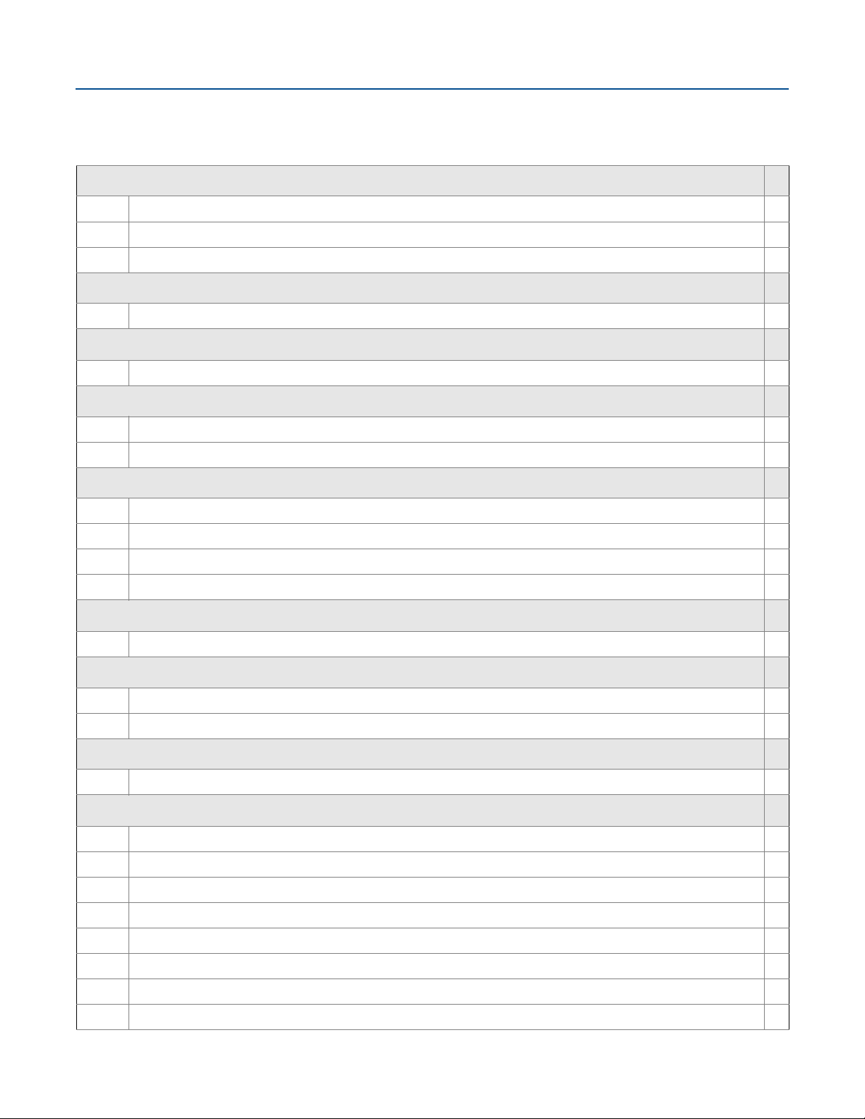
Figure 3. Accuracy over Measuring Range for Rigid Single Lead/Segmented Rigid Single Probes
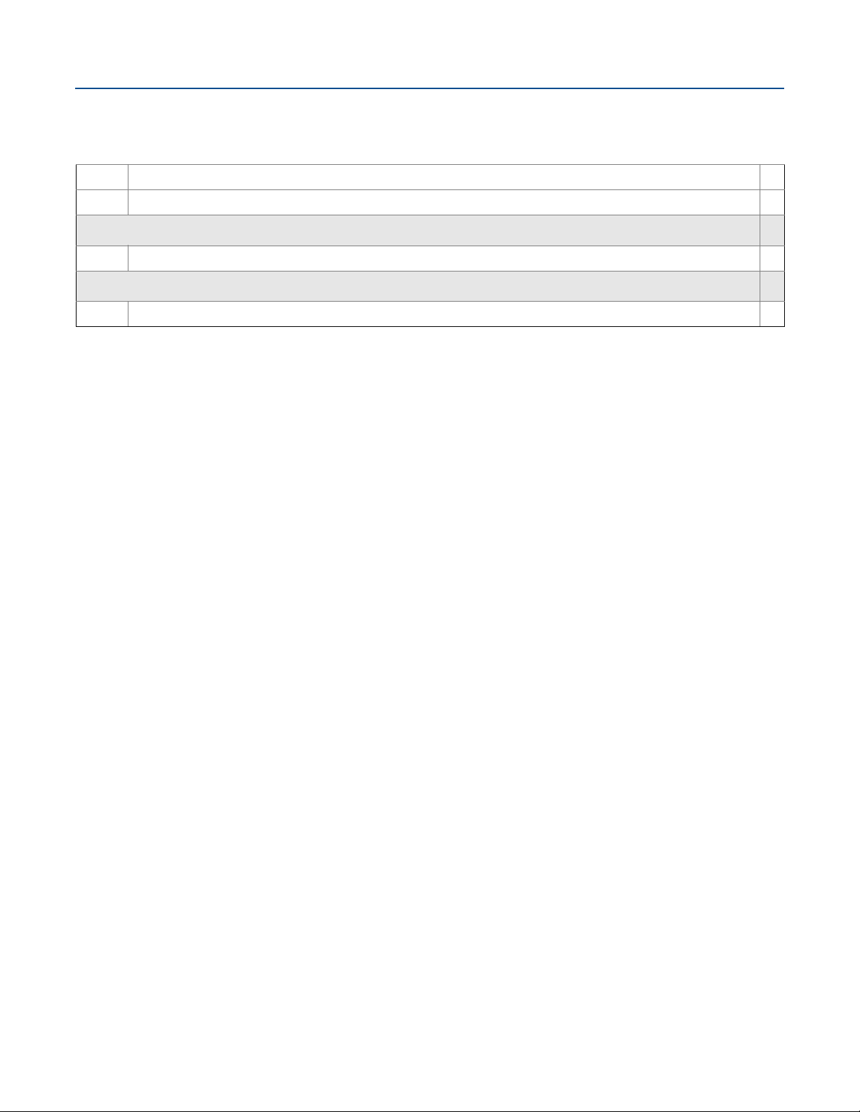
Figure 4. Accuracy over Measuring Range for Flexible Twin Lead Probe
Emerson.com/Rosemount
17
Page 18

Rosemount 3308 Series
5.5 in. (14 cm)
13.0 in. (33 cm)
5.1 in. (13 cm)
5.9 in. (15 cm)
7.1 in. (18 cm)
7.1 in. (18 cm)
2.0 in. (5 cm)
2.0 in.
(5 cm)
3.2 in. (8 cm)
2.8 in.
(7 cm)
±0.12 in.
(3 mm)
±1.18 in.
(30 mm)
±0.12 in.
(3 mm)
±1.18 in.
(30 mm)
±0.25 in.
(6 mm)
±1.18 in.
(30 mm)
6.3 in. (16 cm)
8.3 in. (21cm)
±0.25 in.
(6 mm)
±1.18 in.
(30 mm)
1.2 in. (3 cm)
2 in. (5 cm)
Accuracy
Water (DC = 80) Oil (DC = 2.2)
Blind Zone
Accuracy Accurac y
Standard (profile code S)
Water (DC = 80) Oil (DC = 2.2)
High performance (profile code U)
Figure 5. Accuracy over Measuring Range for Coaxial Probe
January 2018
18
Emerson.com/Rosemount
Page 19

January 2018
Rosemount 3308 Series
Functional specifications
General
Field of applications
Liquids and semi-liquids level or liquid/liquid interfaces
3308Axx1... for level or submerged probe interface
measurement
3308Axx2... for level and interface measurement
Measurement principle
Time Domain Reflectometry (TDR)
(See “Introduction” on page 2 for a description of how it works)
Microwave output power
Nominal 10 μw, Max <20 mW
Humidity limits
0 to 100% relative humidity
Wireless
Output
IEC 62591 (WirelessHART) 2.4 GHz
Transmit rate
User selectable, 4 seconds to 60 minutes
Frequency rate
2400 - 2483.5 MHz
Radio frequency output from antenna
External antenna (WK1 option): < 10 mW (+10dBm) EIRP
Remote (WN1 option): < 40mW (16dBm) EIRP
Modulation type
QPSK/iEEE 802.15.4 IEC 62591 (WirelessHART)
Number of channels
15
Channel spacing
5 MHz
Emission designation
G1D
Display and configuration
LCD display
Toggles between selected output variables
Shows diagnostic information (alerts)
Display updates at each wireless update
Figure 6. LCD Display
Output units
Level, Interface, and Distance: ft, inch, m, cm, or mm
Volume: ft
Tempera tur e: °F, °C
Table 7. Output Variables
Varia ble LCD display PV, SV, TV, QV
Level
Distance
Surface Signal Strength N/A
Total Volume
Interface Level
Interface Distance
Interface Signal Strength
Upper Product Thickness
Electronics Temperature
Signal Quality
Supply Voltage
% of Range
3
, inch3, US gals, Imp gals, barrels, yd3, m3, or liters
(1)
(1)
(1)
(3)
N/A
(2)
(2)
(2)
(2)
(2)
Emerson.com/Rosemount
1. For 3308Axx1, Interface measurement is only available for fully submerged
probe.
2. Not available as primary variable.
3. Only available with 3308Axx2.
19
Page 20

Rosemount 3308 Series
PTFE covered probe and
flange (model code 7)
Pressure psig (bar)
580 (40)
232 (16)
-14 (-1)
-40
(-40)
302
(150)
Tem per atu re ° F (°C)
January 2018
HART diagnostics
Signal Quality Metrics - Diagnostics package that monitors the
relations between surface, noise and threshold. The function
can be used to detect abnormal conditions in the process such
as probe contamination or sudden loss of signal strength. Signal
Quality is available as Output Variable and it comes with user
configurable alerts through AMS Wireless Configurator or Field
Communicator.
Temperature limits
Verify that the operating atmosphere of the transmitter is
consistent with the appropriate hazardous locations
certifications, see “Product Certifications” on page 29.
Table 8. Ambient Temperature Limits
Description Operating limit Storage limit
With LCD display
Without LCD display
1. LCD display may not be readable and device display updates will be slower at
temperatures below -4 °F (-20 °C).
-40 to 175 °F
(-40 to 80° C)
-40 to 185 °F
(-40 to 85° C)
(1)
-40 to 185 °F
(-40 to 85 °C)
-40 to 185 °F
(-40 to 85 °C)
Process temperature and pressure rating
Figure 7 gives the maximum process temperature (measured at
the lower part of the flange or threaded connection) and
pressure rating.
Table 9. Temperature Ranges for Standard Tank Seals
With Different O-ring Materials
O-ring material
Viton Fluoroelastomer 5 (-15) 302 (150)
Ethylene Propylene (EPDM) -40 (-40) 266 (130)
Kalrez 6375 Perfluoroelastomer 14 (-10) 302 (150)
Nitrile Butadiene (NBR) -31 (-35) 230 (110)
Temperature °F (°C) in air
Min. Max.
Note
Always check the chemical compatibility of the O-ring material
with your application. If the O-ring material is not compatible
with its chemical environment, the O-ring may eventually
malfunction.
Flange rating
ASME
316L SST flanges according to ASME B16.5 Table 2-2.3:
Max. 302 °F/580 psig (150 °C/40 bar)
Alloy C-276 (UNS N10276) flanges according to ASME B16.5
Table 2-3.8:
Max. 302 °F/580 psig (150 °C/40 bar)
Final rating depends on flange, material of construction, and
O-ring selection.
Figure 7. Max. Rating, Standard Tank Connections
Duplex 2205 (UNS S31803) flanges according to ASME B16.5
Table 2-2.8:
Max. 302 °F/580 psig (150 °C/40 bar)
EN
EN 1.4404 according to EN 1092-1 material group 13E0:
Max. 302 °F/580 psig (150 °C/40 bar)
Alloy C-276 (UNS N10276) flanges according to EN 1092-1
material group 12E0:
Max. 302 °F/580 psig (150 °C/40 bar)
Duplex 2205 (EN 1.4462) flanges according to EN 1092-1
material group 16E0:
Max. 580 psig (40 Bar), -22 °F (-30 °C) up to max 302 °F (150 °C)
JIS
316L SST Flanges according to JIS B2220 material group 2.3:
Max. 302 °F/580 psig (150 °C/40 bar)
Fisher and Masoneilan
316L SST Flanges according to ASME B16.5 Table 2-2.3:
Max. 302 °F/580 psig (150 °C/40 bar)
1. Minimum temperature limit due to EN13445-2.
(1)
20
Emerson.com/Rosemount
Page 21

January 2018
Product Level
Interface Level
Interface Level
Interface
measurement
Interface measurement with
fully submerged probe
Rosemount 3308 Series
Table 10. Tri Clamp Rating
Size Maximum pressure (bar)
1½-in. (37.5 mm) 16
2-in. (50 mm) 16
3-in. (75 mm) 10
4-in. (100 mm) 10
1. The final rating depends on the clamp and gasket.
(1)
Plate design
Certain models of flanged alloy and PTFE covered probes have a
tank connection design with a protective flange plate of the
same material as the probe and with a backing flange in 316L/EN
1.4404. The protective flange plate prevents the backing flange
from being exposed to the tank atmosphere.
Flange rating according to SST backing flange ASME B16.5 Table
2-2.3, EN 1092-1 material group 13E0, and JIS B2220 material
group 2.3.
PTFE protective plate:
Max. 302 °F/232 psig (150 °C/16 Bar)
Alloy C-276 and Alloy 400 protective plate:
Max. 302 °F/580 psig (150 °C/40 Bar)
The dielectric constant of the upper product must have a
lower dielectric constant than the lower product to have a
distinct reflection.
The difference between the dielectric constants for the two
products must be larger than 10.
Maximum dielectric constant for the upper product is 10 for
the coaxial probe, and 5 for the single lead and flexible twin
lead probes.
Minimum detectable upper product thickness is 4 in. (10 cm)
when the upper product is oil (DC=2.2) and the lower product
is water (DC=80).
For guidelines on emulsion, consult your local Emerson
representative.
For additional information, see the Guided Wave Radar Interface
Measurement Technical Not e
.
Interface measurements
The Rosemount 3308 Series is well suited for interface
measurements, including applications where the probe is fully
submerged in the liquid.
Figure 8. Interface Measurements
If interface is to be measured, follow these criteria:
The dielectric constant of the upper product should be known
and should not vary. The AMS Wireless Configurator and Field
Communicator have a built-in Dielectric Constant Guide to
assist the user in determining the dielectric constant of the
upper product.
Emerson.com/Rosemount
21
Page 22

Rosemount 3308 Series
January 2018
Conditions used for flange strength calculations
Table 11. 316L SST or Process Connection With Plate Design
Standard Bolting material Gasket Flange material Hub material
ASME Stainless steel SA193 B8M Class 2
EN, JIS EN 1515-1/-2 group 13E0, A4-70
Soft (1a) with min.
thickness 1.6 mm
Soft (EN 1514-1) with
min. thickness 1.6 mm
Stainless steel A182 Gr. F316L
and EN 10222-5-1.4404
Stainless steel SA479M
316L and
EN 10272-1.4404
Table 12. Alloy C-276
Standard Bolting material Gasket Flange material Hub material
ASME
EN, JIS
Soft (1a) with min.
thickness 1.6 mm
UNS N10276
Soft (EN 1514-1) with
min. thickness 1.6 mm
SB462 Gr. N10276 (solution
annealed condition) or
SB575 Gr. N10276 (solution
annealed condition)
SB574 Gr. N10276
Table 13. Duplex 2205
Standard Bolting material Gasket Flange material Hub material
ASME A193 B7 or A320 L7
®
EN, JIS Bumax
88
Soft (1a) with min.
thickness 1.6 mm
Soft (EN 1514-1) with
min. thickness 1.6 mm
Duplex stainless steel
SA/A182 F51 and
EN10222-5-1.4462
or SA/A240 Gr. S31803 and
EN10028-7-1.4462
Stainless steel SA479M
S31803 and
EN, JIS Bumax 88 EN
10272-1.4462
22
Emerson.com/Rosemount
Page 23

January 2018
Protective plate
PTFE covered probe
and protective plate
Alloy probe and
protective plate
Tot al P ro be L eng th
NPT BSPP (G) Flange
Upper
Reference
Point
Tri Clamp
Rosemount 3308 Series
Physical specifications
Material selection
Emerson provides a variety of Rosemount products with various
product options and configurations including materials of
construction that can be expected to perform well in a wide
range of applications. The Rosemount product information
presented is intended as a guide for the purchaser to make an
appropriate selection for the application. It is the purchaser’s
sole responsibility to make a careful analysis of all process
parameters (such as all chemical components, temperature,
pressure, flow rate, abrasives, contaminants, etc.), when
specifying product, materials, options and components for the
particular application. Emerson is not in a position to evaluate or
guarantee the compatibility of the process fluid or other process
parameters with the product, options, configuration or
materials of construction selected.
Tank connection
The tank connection consists of a tank seal, a flange, Tri Clamp,
or NPT or BSPP (G) threads. See “Dimensional Drawings” on
page 32.
Certain models of flanged alloy and PTFE covered probes have a
tank connection design with a protective plate of the same
material as the probe (see Figure 9). This is to prevent the
316L/EN 1.4404 SST flange from being exposed to the tank
atmosphere.
Probes
Probe versions
Flexible single lead, rigid single lead, segmented rigid single
lead, flexible twin lead, and coaxial.
Total probe length
This is defined from the Upper Reference Point to the end of the
probe (weight included, if applicable).
Figure 10. Total Probe Length
Figure 9. Probe and Protective Plate
Housing and enclosure
Ingress protection
IP66/67 and NEMA
Flange dimensions
Follows ASME B16.5, JIS B2220, and EN 1092-1 standards for
blind flanges. For Proprietary Fisher and Masoneilan flanges, see
“Proprietary Flanges” on page 39.
®
4X
Select the probe length according to the required measuring
range (the probe must be hung and fully extended through the
entire distance where level readings are desired).
Cut-to-fit probes
All probes can be cut in field except for the PTFE covered probe.
However, there are some restrictions for the coaxial probe: Probes
over 4.1 ft. (1.25 m) can be cut up to 2 ft. (0.6 m). Shorter probes
can be cut to the minimum length of 1.3 ft. (0.4 m).
Table 14. Minimum and Maximum Probe Length
Probe type Probe length
Flexible single lead 3.3 to 55.8 ft. (1 to 17 m)
Rigid single lead (0.3-in./8 mm) 1.3 to 9.8 ft. (0.4 to 3 m)
Rigid single lead (0.5-in./13 mm) 1.3 to 19.7 ft. (0.4 to 6 m)
Segmented rigid single lead 1.3 to 32.8 ft. (0.4 to 10 m)
Flexible twin lead 3.3 to 55.8 ft. (1 to 17 m)
Coaxial 1.3 to 19.7 ft. (0.4 to 6 m)
Probe angle
0 to 90 degrees from vertical axis
Emerson.com/Rosemount
23
Page 24

Rosemount 3308 Series
January 2018
Tensile strength
Flexible single lead SST: 2698 lb (12 kN)
Flexible single lead Alloy C-276: 1798 lb (8 kN)
Flexible single lead Alloy 400: 1124 lb (5 kN)
Flexible single lead Duplex 2205: 1349 lb (6 kN)
Flexible twin lead: 2023 lb (9 kN)
Collapse load
Flexible single lead SST: 3597 lb (16 kN)
Flexible single lead Alloy C-276: 2023 lb (9 kN)
Flexible single lead Alloy 400: 1349 lb (6 kN)
Flexible single lead Duplex 2205: 1574 lb (7 kN)
Sideway capacity
Rigid single lead/segmented rigid single lead:
4.4 ft. lbf, 0.44 lb at 9.8 ft. (6 Nm, 0.2 kg at 3 m)
Coaxial: 73.7 ft. lbf, 3.7 lb at 19.7 ft. (100 Nm, 1.67 kg at 6 m)
Material exposed to tank atmosphere
Material of
construction code
1
2
3
7 PTFE (1 mm PTFE cover)
8
H
D
1. For flexible single/twin lead probes only.
Material
316 SST
(1)
, 316L SST (EN 1.4404), PTFE,
PFA, and O-ring materials
Alloy C-276 (UNS N10276), PTFE, PFA,
and O-ring materials
Alloy 400 (UNS N04400), PTFE, PFA, and
O-ring materials
PTFE, 316L SST (EN 1.4404), and O-ring
materials
Alloy C-276 (UNS N10276), PTFE, PFA,
and O-ring materials
Duplex 2205 (UNS S31803/EN 1.4462),
Duplex 2507 (UNSS32750/EN 1.4410),
PTFE, PFA, and O-ring materials
Weight
Table 15. Flange and Probes
Item Weight
Flange Depends on flange size
Flexible single lead probe 0.05 lb/ft. (0.07 kg/m)
Rigid single lead probe
(0.3-in./8 mm)
Rigid single lead probe
(0.5-in./13 mm)
Segmented rigid single
lead probe
0.27 lb/ft. (0.4 kg/m)
0.71 lb/ft. (1.06 kg/m)
0.71 lb/ft. (1.06 kg/m)
Flexible twin lead probe 0.09 lb/ft. (0.14 kg/m)
Coaxial probe 0.67 lb/ft. (1 kg/m)
Table 16. End Weight
Item
Small weight (code W1)
Short weight (code W2) 0.88 lb (0.40 kg)
Heavy weight (code W3) 2.43 lb (1.10 kg)
Flexible twin lead probe 1.3 lb (0.60 kg)
Weight
SST probe: 0.88 lb (0.40 kg)
PTFE covered probe: 2.20 lb (1 kg)
End weight and anchoring options
There are in total four weight and anchoring options for flexible
single lead probes. See Figure 15 on page 32 for dimensions.
Small weight (code W1)
A small weight is recommended for narrow tank openings less
than 1.5 in. (38 mm). Required weight option for PTFE covered
probes.
Short weight (code W2)
A short weight is available for the single flexible stainless steel
probe. It is recommended for maximized measuring ranges with
measurements close to the probe end.
Heavy weight (code W3)
A heavy weight is the recommended choice for most
applications.
Chuck (code W4)
To tie probe end to tank bottom.
24
Emerson.com/Rosemount
Page 25

January 2018
Nozzle diameter
Nozzle height
Clearance to tank wall
Table 17. Minimum Clearance
Rosemount 3308 Series
Description Flexible single lead Rigid single lead/
Flexible twin lead Coaxial
segmented rigid single lead
Recommended
nozzle diameter
4 in. (100 mm) or more 4 in. (100 mm) or more 4 in. (100 mm) or more > probe diameter
1.5 in. (38 mm)
Min. nozzle
diameter
(1)
1.5 in. (38 mm)
for probe type 4A
2 in. (50 mm) > probe diameter
2 in. (50 mm)
for probe type 4B and 4S
Maximum nozzle
height
Min. clearance to
tank wall or
obstruction
Min. pipe/bypass
diameter
1. The Trim Near Zone (TNZ) function may be necessary or an Upper Null Zone (UNZ) setup may be required to mask the nozzle.
2. For nozzles taller than 4 in. (100 mm), the Long Stud version is recommended (option code LS) to prevent the flexible portion from tou ching the edge of the nozz le.
4 in. (100 mm) +
nozzle diameter
(2)
4 in. (100 mm) if smooth
metallic wall.
16 in. (400 mm) if
disturbing objects or
rugged metallic.
Consult your local Emerson
representative.
4 in. (100 mm) +
nozzle diameter
4 in. (100 mm) if smooth
metallic wall.
16 in. (400 mm) if disturbing
objects or rugged metallic.
2 in. (50 mm)
4 in. (100 mm) +
nozzle diameter
4 in. (100 mm) if smooth
metallic wall.
16 in. (400 mm) if
disturbing objects or
rugged metallic.
Consult your local Emerson
representative.
N/A
0 in. (0 mm)
1.5 in. (38 mm)
Figure 11. Mounting in Nozzles and Free Space Requirement
Emerson.com/Rosemount
25
Page 26

Rosemount 3308 Series
Metal flange Metal sheet
(d > 14 in./350 mm)
Flexible single lead
probe with chuck
January 2018
Installation in non-metallic tanks and open-air
applications
Avoid major sources of electrical disturbance in proximity of
the installation, e.g. electrical motors, stirrers, servo
mechanisms.
For clean liquids, use a coaxial probe to reduce effect of
potential electrical disturbances.
Other mechanical considerations
To get best possible performance, the following must be
considered before installing the transmitter:
Inlets should be kept at a distance in order to avoid product
filling on the probe.
Avoid physical contact between probes and agitators, as well
as applications with strong fluid movement unless the probe
is anchored.
Probe tie-down is recommended if the probe can move to
within 1 ft. (30 cm) of any object during operations.
In order to stabilize the probe for side forces, it is possible to
fix or guide the probe to the tank bottom
For optimal single lead probe performance in non-metallic
tanks, the probe must be mounted with a metal flange, or
screwed in to a metal sheet (d > 14 in./350 mm) if a threaded
version is used.
Make sure the nozzle does not extend into the tank.
See the Rosemount 3308 Series Wireless Guided Wave Radar,
3308A Reference Manual
for more mechanical installation
information.
Engineered solutions
When standard model codes are not sufficient to fulfill
requirements, please consult the factory to explore possible
Engineered Solutions. This is typically, but not exclusively,
related to the choice of wetted materials or the design of a
process connection. These Engineered Solutions are part of the
expanded offerings and may be subject to additional delivery
lead time. For ordering, factory will supply a special P-labeled
numeric option code that should be added at the end of the
standard model string.
26
Emerson.com/Rosemount
Page 27

January 2018
Centre-to-centre
Side-and-bottom
dimension
Side-and-side
dimension
Centre-to-centre
Replace chamber flange
Displacer
length
Probe
length
Rosemount 3308 Series
Chamber/pipe installations
General chamber considerations
A chamber or pipe installation is the preferred option due to the
increase in stability and performance of the transmitter. When
selecting a smaller diameter chamber or pipe (such as 2-in.) a
flexible probe is not suitable due to the chance of it coming into
contact with the walls, and relatively large side inlets may
interfere with the signal.
When gas lift and/or turbulence may occur (e.g. boiling
hydrocarbons), a 3- or 4-in. chamber/pipe diameter is
recommended for maximum measurement reliability. This is
especially true in high pressure and high temperature
installations.
Rosemount 9901 Chamber
Rosemount 9901 allows external mounting of process level
instrumentation. It supports a variety of process connections,
and optional drain and vent connections. The Rosemount 9901
chamber is designed to the ASME B31.3 standard, and is
Pressure Equipment Directive (PED) compliant. Use option code
XC to order together with the Rosemount 3308 Series
Transmitters.
Figure 12. Rosemount 9901 Chamber
For additional information, see the Rosemount 9901 Chamber
for Process Level Instrumentation Product Data Sheet
.
Existing chamber
A Rosemount 3308 Series Transmitter is the perfect
replacement in an existing displacer chamber. Proprietary
flanges are offered, enabling use of existing chambers to make
installation easy.
Figure 13. Existing Displacer Chamber
Considerations when changing to Rosemount 3308 Series:
The Rosemount 3308 Series flange choice and probe length
must be correctly matched to the chamber. Both standard
ANSI and EN (DIN), as well as proprietary chamber flanges, are
available. See “Proprietary Flanges” on page 39 to identify the
proprietary flanges.
See Table 20 on page 28 for guidelines on which disc size to use.
See Table 18 for guidelines on the required probe length.
The probe length to use for a Rosemount 9901 chamber can be
calculated with this formula:
Side-and-side dimension:
Probe length = Centre-to-centre dimension + 19 in. (48 cm)
Side-and-bottom dimension:
Probe length = Centre-to-centre dimension + 4 in. (10 cm)
Use a centering disc the same diameter as the chamber if the
probe length >3.3 ft. (1 m). See Table 20 on page 28 for which
disc to use.
Emerson.com/Rosemount
Table 18. Required Probe Length in Chambers
Chamber manufacturer Probe length
Major torque-tube manufacture
(249B, 249C, 249K, 249N, 259B)
Masoneilan (Torque tube
operated), proprietary flange
Other - torque tube
(2)
Displacer + 9 in. (229 mm)
Displacer + 8 in. (203 mm)
Displacer + 8 in. (203 mm)
Displacer + between
Magnetrol
®
(spring operated)
(3)
7.8 in. (195 mm) to 15 in.
(383 mm)
Others - spring operated
1. If flushing ring is used, add the ring height to the probe length.
2. For other manufac turers, there are small variations. This is an approximate
value, actual length should be verified.
3. Lengths vary depending on model, SG and rating, and should be verified.
(2)
Displacer +
19.7 in. (500 mm)
For additional information, see the Replacing Displacers with
Guided Wave Radar Tech nic al No te.
(1)
27
Page 28

Rosemount 3308 Series
D
January 2018
Probe type in chamber considerations
When installing a Rosemount 3308 in a chamber, the single lead
probe is recommended. The probe length determines if a single
rigid or single flexible probe should be used:
Less than 19.7 ft. (6.0 m):
Rigid single probe is recommended. Use a centering disc for
probe > 3.3 ft. (1 m). When mounting space is limited, use a
flexible single probe with a weight and centering disc.
More than 19.7 ft. (6.0 m):
Use flexible single probe with a weight and centering disc.
PTFE covered probes are not recommended for chamber/pipe
installations.
Centering discs
To prevent the probe from contacting the chamber or pipe wall,
centering discs are available for rigid single, flexible single, and
flexible twin lead probes. The disc is attached to the end of the
probe. Discs are made of stainless steel, Alloy C-276, Duplex
2205, or PTFE.
Figure 14. Actual Disc Diameter (D)
Table 20. Centering Disc Size Recommendation for
Different Pipe Schedules
Pipe size Pipe schedule
5s, 5 and
10s,10
2-in. 2-in. 2-in. N/A
3-in. 3-in. 3-in. N/A
4-in. 4-in. 4-in. 4-in. 3-in.
5-in. 4-in. 4-in. 4-in. 4-in.
6-in. 6-in. 6-in. 4-in. 4-in.
7-in. N/A
8-in. 8-in. 8-in. 6-in. 6-in.
1. Schedule is not available for pipe size.
2. No centering disc is available.
(1)
40s, 40 and
80s, 80
6-in. N/A
120 160
(1)
(1)
(1)
N/A
2-in.
N/A
(2)
(1)
For the segmented rigid single lead probe, up to five PTFE
centering discs can be mounted along the probe, but keep a
minimum distance of two segments between the discs.
Additionally, a disc in SST or PTFE (part number
03300-1655-xxxx) can be attached to the end of the probe.
When mounting a centering disc, it is important that it fits
correctly in the chamber/pipe. See Table 19 for Dimension D.
Table 20 shows which centering disc diameter to choose for a
particular pipe.
Table 19. Centering Disc Dimensions
Disc size Actual disc diameter (D)
2-in. 1.8 in. (45 mm)
3-in. 2.7 in. (68 mm)
4-in. 3.6 in. (92 mm)
6-in. 5.55 in. (141 mm)
8-in. 7.40 in. (188 mm)
28
Emerson.com/Rosemount
Page 29

January 2018
Product Certifications
Rosemount 3308 Series
European Union directive information
The EU Declaration of Conformity for all applicable European
directives for this product can be found on
Emerson.com/Rosemount. A hard copy may be obtained by
contacting your local sales representative.
Telecommunication compliance
All wireless devices require certification to ensure that they
adhere to regulations regarding the use of the RF spectrum.
Nearly every country requires this type of product certification.
Emerson is working with governmental agencies around the
world to supply fully compliant products and remove the risk of
violating country directives or laws governing wireless device
usage.
FCC and IC
This device complies with Part 15 of the FCC Rules. Operation is
subject to the following conditions: This device may not cause
harmful interference that may cause undesired operation
This device must be installed to ensure a minimum antenna
separation distance of 20 cm from all persons.
This radio transmitter has been approved by Industry Canada to
operate with the antenna types listed below with the maximum
permissible gain indicated. Antenna types not included in this
list, having a gain greater than the maximum gain indicated for
that type, are strictly prohibited for use with this device.
Antenna model
option
WK1 Integral Omni-directional 2
WN1 Remote Omni-directional 8
This device complies with Industry Canada license-exempt RSS
standard(s). Operation is subject to the following two
conditions: (1) This device may not cause interference, and (2)
this device must accept any interference, including any
interference that may cause undesired operation of the device.
Caution
Changes or modifications to the equipment not expressly approved by
Emerson could void the user’s authority to operate the equipment.
Antenna type Max gain
(dBi)
Ordinary location certification for FM
approvals
As standard, the transmitter has been examined and tested to
determine that the design meets basic electrical, mechanical,
and fire protection requirements by FM Approvals, a nationally
recognized testing laboratory (NRTL) as accredited by the
Federal Occupational Safety and Health Administration (OSHA).
Hazardous locations certificates
U.S.A.
I5 U.S.A Intrinsically Safe
Certificate: FM17US0014X
Standards: FM Class 3600 – 2011, FM Class 3610 – 2015,
FM Class 3810 – 2005, NEMA 250 – 2003,
ANSI/ISA 60079-0:2013,
ANSI/UL 60079-11:2014,
ANSI/ISA 60529:2004, ANSI/ISA 61010-1:2004
Markings: IS CL I, DIV 1, GP A, B, C, D:
IS CL I Zone 0, AEx ia IIC T4 Ga;
T4 Ta = -55 to +70 °C
Type 4X; IP66; IP67
WHEN INSTALLED PER ROSEMOUNT DRAWING
03308-1010
Special Conditions of Certification:
1. The Model 3308 transmitter housing contains aluminum;
protect the enclosure to avoid a potential risk of ignition
due to impact or friction.
2. The surface resistivity of the polymeric antenna is greater
than 1G. To avoid electrostatic charge buildup, it must
not be rubbed or cleaned with solvents or a dry cloth.
3. For use only with the Emerson Process Management Model
701PBKKF SmartPower Option or the Computational
Systems, Inc Model MHM-89004 battery module.
4. Only the Emerson Process Management 375 or 475 Field
Communicator is approved for use with this transmitter.
5. The maximum permitted operating temperature of the
Rosemount 3308A transmitter is 70 °C. To avoid the
effects of process temperature and other thermal effects
care shall be taken to ensure that the “Electronics
Temperature” does not exceed 70 °C.
Canada
I6 Canada Intrinsically Safe
Certificate: FM17CA0007X
Standards: CSA Std. C22.2 No. 61010-1:2004,
CSA Std. 22.2 No. 94-M91,
CAN/CSA-C22.2 NO. 60079-0:15,
CAN/CSA-C22.2 NO. 60079-11:14,
C22.2 No. 60529:2016
Emerson.com/Rosemount
29
Page 30

Rosemount 3308 Series
January 2018
Markings: INTRINSICALLY SAFE Ex ia
CLASS I, GP A, B, C, D;
CLASS I, Zone 0, Ex ia IIC T4 Ga;
TEMP CODE T4 (-55 °C
Type 4X; IP66; IP67
WHEN INSTALLED PER ROSEMOUNT DRAWING
03308-1010
Special Conditions of Certification:
1. The Model 3308 transmitter housing contains aluminum;
protect the enclosure to avoid a potential risk of ignition
due to impact or friction.
2. The surface resistivity of the polymeric antenna is greater
than 1G. To avoid electrostatic charge buildup, it must
not be rubbed or cleaned with solvents or a dry cloth.
3. For use with the Emerson Process Management 701PBKKF
SmartPower Option or the Computational Systems, Inc
Model MHM-89004 battery module only.
4. Only the Emerson Process Management 375 or 475 Field
Communicator is approved for use with this transmitter.
5. The maximum permitted operating temperature of the
Rosemount 3308A transmitter is 70 °C. To avoid the
effects of process temperature and other thermal effects
care shall be taken to ensure that the “Electronics
Temperature” does not exceed 70 °C.
Ta +70 °C)
Europe
I1 ATEX Intrinsic Safe
Certificate: FM 12ATEX0072X
Standards: EN 60079-0:2012+A11:2013, EN
60079-11:2012; EN 60529:1991+A2:2013
Markings: Category II 1 G, Ex ia IIC T4 Ga
(-55 °C
1180
2460
Special Conditions of Certification:
1. The Model 3308 transmitter housing contains aluminum;
protect the enclosure to avoid a potential risk of ignition
due to impact or friction.
2. The surface resistivity of the polymeric antenna is greater
than 1G. To avoid electrostatic charge buildup, it must
not be rubbed or cleaned with solvents or a dry cloth.
3. For use only with the ATEX certified
(Baseefa11ATEX0042X) Emerson Process Management
Model 701PBKKF SmartPower Option or the ATEX certified
(SIRA 15ATEX2332X) Computational Systems, Inc Model
MHM-89004 battery Module.
4. Only an ATEX certified (BVS03ATEXE347,
BVS09ATEXE023) Emerson Process Management 375 or
475 Field Communicator is approved for use with this
transmitter.
Ta +70 °C);
5. The maximum permitted operating temperature of the
Rosemount 3308A transmitter is 70 °C. To avoid the
effects of process temperature and other thermal effects
care shall be taken to ensure that the “Electronics
Temperature” does not exceed 70 °C.
International
I7 IECEx Intrinsic Safety
Certificate: IECEx FMG 12.0029X
Standards: IEC 60079-0: 2011, IEC 60079-11: 2011
Markings: Ex ia IIC T4 Ga (-55 °C
Special Conditions of Certification:
1. The Model 3308 transmitter housing contains aluminum;
protect the enclosure to avoid a potential risk of ignition
due to impact or friction.
2. The surface resistivity of the polymeric antenna is greater
than 1G. To avoid electrostatic charge buildup, it must
not be rubbed or cleaned with solvents or a dry cloth.
3. For use with only the an IECEx certified (IECEx FMG
12.0029X) Emerson Process Management Model
701PBKKF SmartPower Option or the IECEx certified (IECEx
CSA 15.0045X) Computational Systems, Inc Model
MHM-89004 battery pack.
4. Only the Emerson Process Management 375 or 475 Field
Communicator is approved for use with this transmitter.
5. The maximum permitted operating temperature of the
Rosemount 3308A transmitter is 70 °C. To avoid the
effects of process temperature and other thermal effects
care shall be taken to ensure that the “Electronics
Temperature” does not exceed 70 °C.
Ta +70 °C)
Brazil
I2 INMETRO Intrinsic Safety
Certificate: UL-BR 13.0463X
Standards: ABNT NBR IEC 60079-0:2008 + Errata 1:2011,
ABNT NBR IEC 60079-11:2009,
ABNT NBR IEC 60079-26:2008
Markings: Ex ia IIC T4 Ga (-55 °C <
Special Conditions of Certification:
1. The Model 3308 transmitter housing contains aluminium;
protect the enclosure to avoid a potential risk of ignition
due to impact or friction.
2. The surface resistivity of the polymeric antenna is greater
than 1 G. To avoid electrostatic charge buildup, it must
not be rubbed or cleaned with solvents or a dry cloth.
3. For use with the Emerson Process Management 701PB
SmartPower Option only.
4. Only the Emerson Process Management 375 or 475 Field
Communicator is approved for use with this transmitter.
T
amb
< +70 °C)
30
Emerson.com/Rosemount
Page 31

January 2018
Rosemount 3308 Series
5. The maximum permitted operating temperature of the
Rosemount 3308A transmitter is 70 °C. To avoid the
effects of process temperature and other thermal effects
care shall be taken to ensure that the “Electronics
Temperature” does not exceed 70 °C.
China
I3 NEPSI Intrinsic Safety
Certificate: GYJ13.1443X
Standards: GB 3836.1-2010, GB 3836.4-2010,
GB 3836.20-2010
Markings: Ex ia IIC T4 Ga (-55°C
Special Conditions of Certification:
See certificate for details.
+70°C)
~
Japan
I4 TIIS Intrinsic Safety
Certificate: TC20746
Markings: Ex ia IIC T4 -20°~+60°C
Special Conditions of Certification:
See certificate for details.
EAC – Belarus, Kazakhstan, Russia
IM Technical Regulation Customs Union (EAC) Intrinsic Safety
Certificate: RU C-US.Gb05.B.00530
Markings: 0Ex ia IIC T4 Ga X (-55°C
Special Conditions of Certification:
See certificate for details.
Ta +70 °C)
Combinations
KD ATEX and Canadian Intrinsic Safety
KE FM and Canadian Intrinsically Safe
KF ATEX and FM Intrinsic Safety
Other certifications
U1 Overfill protection
Certificate: Z-65.16-536
TÜV-tested and approved by DIBt for overfill protection
according to the German WHG regulations
Ta iwa n
注意!
依據 低功率電波輻射性電機管理辦法
第十二條
經型式認證合格之低功率射頻電機,非經
許可,公司、商號或使用者均不得擅自變更頻
率、加大功率或變更原設計之特性及功能。
第十四條
低功率射頻電機之使用不得影響飛航安全
及干擾合法通信;經發現有干擾現象時,應立
即停用,並改善至無干擾時方得繼續使用。
前項合法通信,指依電信法規定作業之無
線電通信。
低功率射頻電機須忍受合法通信或工業、科學
及醫療用電波輻射性電機設備之干擾。
Emerson.com/Rosemount
31
Page 32

Rosemount 3308 Series
12 (297.2)
3.9 (100.2)
2.8 (71.3)
External antenna
(option WK1)
L 56 ft.
(17 m)
Ø 0.16 (4): SST probe
Ø 0.28 (7): PTFE covered probe
5.5
(140)
Ø 0.9 (22)
BSPP (G) 1-in., s52
BSPP (G) 1½-in., s60
Short weight
(option W2)
2 (50)
Ø 1.5 (38)
Heavy weight
(option W3)
5.5
(140)
Ø 1.5 (38)
Chuck
(option W4)
Ø 1 (24.5)
1 (26)
4.3 (110)
7.8 (198)
Min. 8 (200)
Chamber/pipe
Min. Ø 2 (50)
The probe must be
in the center of the
probe/chamber
PTFE covered probe and
protective plate
Small weight
(option W1)
Weight for PTFE
covered probe
(option W1)
17.1
(435)
Ø 0.88 (22.5)
Thread sealing
NPT 1-in., s52
NPT 1½-in., s52
NPT 2-in., s60
Protective plate
2.4 (62)
1.9 (47)
2.4 (62)
3.4 (86)
Min. 4 (100) if smooth metallic wall.
Min. 16 (400) if disturbing objects or
rugged metallic wall.
H (Nozzle height)
H < 4 (100) + D
Tri Clamp
connection
12 (297.2)
4 (100): Standard length
10 (250): Long stud (option LS)
0.6 (15)
Alloy probe and
protective plate
Protective plate
Recommended: D > 4 (100)
Minimum: D=1.5 (38)
(1)
Ø D (Nozzle diameter)
Dimensional Drawings
Figure 15. Flexible Single Lead Probe
January 2018
1. The Trim Near Zone (TNZ) function may be necessary or an Upper Null Zone (UNZ) setup may be required to mask the nozzle.
Dimensions are in inches (millimeters).
32
Emerson.com/Rosemount
Page 33

January 2018
PTFE covered probe and
protective plate
Tri Clamp
connection
Recommended: D > 4 (100)
Minimum: D=1.5 (38) for probe type 4A
(1)
D=2 (50) for probe type 4B
(1)
Ø D (Nozzle diameter)
12 (297.2)
3.9 (100.2)2.8 (71.3)
External antenna
(option WK1)
Ø 0.31 (8) or Ø 0.51 (13): SST probe
Ø 0.47 (12): PTFE covered probe
BSPP (G) 1-in., s52
BSPP (G) 1½-in., s60
2.4 (62)
Thread sealing
Min. 8 (200)
Chamber/pipe
Min. Ø 2 (50)
NPT 1-in., s52
NPT 1½-in., s52
NPT 2-in., s60
1.9 (47)
2.4 (62)
3.4 (86)
4.3 (110)
L 10 ft. (3 m)
for Ø 0.31 (8)
L 20 ft. (6 m)
for Ø 0.51 (13)
Protective plate
Min. 0.2 (5)
The probe must be
in the center of the
probe/chamber
Min. 4 (100) if smooth metallic wall.
Min. 16 (400) if disturbing objects or
rugged metallic wall.
7.8 (198)
Nozzle height (H)
H < 4 (100) + D
12 (297.2)
Protective plate
Alloy probe and
protective plate
Figure 16. Rigid Single Lead Probe
Rosemount 3308 Series
1. The Trim Near Zone (TNZ) function may be necessary or an Upper Null Zone (UNZ) setup may be required to mask the nozzle.
Dimensions are in inches (millimeters).
Emerson.com/Rosemount
33
Page 34

Rosemount 3308 Series
Recommended: D > 4 (100)
Minimum: D=2 (50)
(1)
Ø D (Nozzle diameter)
12 (297.2)
3.9 (100.2)2.8 (71.3)
External antenna
(option WK1)
Ø 0.51 (13)
BSPP (G) 1½-in., s60
2.4 (62)
Thread sealing
Min. 8 (200)
Chamber/pipe
Min. Ø 2 (50)
NPT 1½-in., s52
NPT 2-in., s60
1.9 (47)
2.4 (62)
3.4 (86)
4.3 (110)
L 33 ft.
(10 m)
Min. 0.2 (5)
The probe must be
in the center of the
probe/chamber
Min. 4 (100) if smooth metallic wall.
Min. 16 (400) if disturbing objects or
rugged metallic wall.
7.8 (198)
Nozzle height (H)
H < 4 (100) + D
15.2 (385)
0.6 (15)
31.5 (800)
Optional:
PTFE centering disc
Optional:
Bottom centering disc (SST or PTFE)
Figure 17. Segmented Rigid Single Lead Probe
January 2018
1. The Trim Near Zone (TNZ) function may be necessary or an Upper Null Zone (UNZ) setup may be required to mask the nozzle.
Dimensions are in inches (millimeters).
34
Emerson.com/Rosemount
Page 35

January 2018
12 (297.2)
3.9 (100.2)2.8 (71.3)
External antenna
(option WK1)
Min. Ø 1.2 (30)
Metallic contact with
nozzle or tank allowed
Ø 1.1 (28)
Min. 0.2 (5)
1.1 (27)
BSPP (G) 1-in., s52
BSPP (G) 1½-in., s60
2.4 (62)
Thread sealing
Min. 8 (200)
Chamber/pipe
Min. Ø 1.3 (32)
NPT 1-in., s52
NPT 1½-in., s52
NPT 2-in., s60
1.9 (47)
2.4 (62)
3.4 (86)
4.3 (110)
L
20 ft.
(6 m)
Min. 0
to tank wall
7.8 (198)
Nozzle diameter
Protective plate
Alloy probe and
protective plate
Figure 18. Coaxial Probe
Rosemount 3308 Series
Dimensions are in inches (millimeters).
Emerson.com/Rosemount
35
Page 36

Rosemount 3308 Series
12 (299.5)
3.9 (100.2)2.8 (71.3)
External antenna
(option WK1)
Min. Ø 3 (75)
Ø 1.4 (35)
Min. 0.2 (5)
BSPP (G) 1½-in., s60
1.1 (27)
Thread sealing
Min. 8 (200)
Chamber/pipe
3.5 (90)
NPT 1½-in., s52
NPT 2-in., s60
1.1 (27)
1.8 (45)
3.5 (88)
4.3 (110)
L
56 ft.
(17 m)
Ø 0.16 (4)
Ø 0.16 (4)
Ø D (Nozzle diameter)
Recommended: D > 4 (100)
Minimum: D=2 (50)
(1)
1.8 (45)
Nozzle height (H)
H < 4 (100) + D
7.8 (198)
Min. 4 (100) if smooth metallic wall.
Min. 16 (400) if disturbing objects or
rugged metallic wall.
Figure 19. Flexible Twin Lead Probe
January 2018
1. The Trim Near Zone (TNZ) function may be necessary or an Upper Null Zone (UNZ) setup may be required to mask the nozzle.
Dimensions are in inches (millimeters).
36
Emerson.com/Rosemount
Page 37

January 2018
2.2
(57)
0.3 (7)
0.8 (20)
2.8
(70)
5.2
(133)
Pipe mounting
(vertical pipe)
Pipe mounting
(horizontal pipe)
Wall mounting
Pipe diameter,
max 2.5 in. (64 mm)
Hole pattern for wall mounting
NPT 1½-in.
Figure 20. Mounting Bracket (Option Code BR)
Rosemount 3308 Series
Dimensions are in inches (millimeters).
Emerson.com/Rosemount
37
Page 38

Rosemount 3308 Series
I
N
E
X
P
L
O
S
I
V
E
A
T
M
O
S
P
H
E
R
E
K
E
E
P
T
I
G
H
T
W
H
E
N
C
I
R
C
U
I
T
A
L
I
V
E
Antenna
Mounting bracket
RF lightning arrestor
25 ft. (7.6 m)
cable
Minimum drip loop
Ø12 (300)
5/16-18 UNC-2A
thread, 2PLS
U-bolt
Mounting bracket
Antenna
Mounting bracket
U-bolt
0.53 (13.5)
2.50 (63.5)
0.13 (3.3)
4.22 (107.2)
3.80 (96.5)
1.05 (26.7)
Ø 0.66 (16.7)
Ø 0.41 (10.4)
2.75 (69.9)
2.75 (69.9)
0.50 (12.7)
Ø 0.31 (7.9)
4.04 (102.7)
2.40 (61.0)
2.43 (61.7)
20.2 (513)
Ground connection
point
Figure 21. High Gain, Remote Antenna (Option Code WN1)
January 2018
Dimensions are in inches (millimeters).
38
Emerson.com/Rosemount
Page 39

January 2018
D
B
1
G
Raised face Recessed face
K
D: Outside diameter
B
1
: Flange thickness with gasket surface
B
2
: Flange thickness without gasket surface
F=B
1-B2
: Gasket surface thickness
G: Gasket surface diameter
# Bolts: Number of bolts
K: Bolt hole circle diameter
G
B
1
DK
B
2
B
2
#
Rosemount 3308 Series
Figure 22. Proprietary Flanges
Dimensions are in inches (millimeters).
Note
Dimensions may be used to aid in the identification of installed flanges. It is not intended for manufacturing use.
Table 21. Dimensions of Proprietary Flanges
Special flanges
Fisher 249B/259B
Fisher 249C
Masoneilan
1. These flanges are also available in a vented version.
2. Flange with raised face.
3. Flange with recessed face.
(1)
(2)
(3)
(2)
Complementary point level monitoring
An ideal complement to the Rosemount 3308, the Rosemount
2160 Wireless Level Detector provides reliable high/low level
alarms and overfill protection, wirelessly communicating output
and advanced instrument health.
With an update rate of up to one second, the Rosemount 2160
may be used in both monitoring and control applications.
See the Rosemount 2160 Product Data Sheet
Emerson.com/Rosemount
D B
1
B
2
F G # Bolts K
9.00 (228.6) 1.50 (38.2) 1.25 (31.8) 0.25 (6.4) 5.23 (132.8) 8 7.25 (184.2)
5.69 (144.5) 0.94 (23.8) 1.13 (28.6) -0.19 (-4.8) 3.37 (85.7) 8 4.75 (120.65)
7.51 (191.0) 1.54 (39.0) 1.30 (33.0) 0.24 (6.0) 4.02 (102.0) 8 5.87 (149.0)
.
39
Page 40

Rosemount 3308 Series
January 2018
40
Emerson.com/Rosemount
Page 41

January 2018
Rosemount 3308 Series
Emerson.com/Rosemount
41
Page 42

Rosemount 3308 Series
00813-0100-4308, Rev DB
Global Headquarters
Emerson Automation Solutions
6021 Innovation Blvd.
Shakopee, MN 55379, USA
+1 800 999 9307 or +1 952 906 8888
+1 952 949 7001
RFQ.RMD-RCC@Emerson.com
North America Regional Office
Emerson Automation Solutions
8200 Market Blvd.
Chanhassen, MN 55317, USA
+1 800 999 9307 or +1 952 906 8888
+1 952 949 7001
RMT-NA.RCCRFQ@Emerson.com
Latin America Regional Office
Emerson Automation Solutions
1300 Concord Terrace, Suite 400
Sunrise, FL 33323, USA
+1 954 846 5030
+1 954 846 5121
RFQ.RMD-RCC@Emerson.com
Product Data Sheet
January 2018
Linkedin.com/company/Emerson-Automation-Solutions
Europe Regional Office
Emerson Automation Solutions Europe GmbH
Neuhofstrasse 19a P.O. Box 1046
CH 6340 Baar
Switzerland
+41 (0) 41 768 6111
+41 (0) 41 768 6300
RFQ.RMD-RCC@Emerson.com
Asia Pacific Regional Office
Emerson Automation Solutions Asia Pacific Pte Ltd
1 Pandan Crescent
Singapore 128461
+65 6777 8211
+65 6777 0947
Enquiries@AP.Emerson.com
Middle East and Africa Regional Office
Emerson Automation Solutions
Emerson FZE P.O. Box 17033
Jebel Ali Free Zone - South 2
Dubai, United Arab Emirates
+971 4 8118100
+971 4 8865465
RFQ.RMTMEA@Emerson.com
Twitter.com/Rosemount_News
Facebook.com/Rosemount
Youtube.com/user/RosemountMeasurement
Google.com/+RosemountMeasurement
Standard Terms and Conditions of Sale can be found on the Term s an d
Conditions of Sale page.
The Emerson logo is a trademark and service mark of Emerson Electric
Co.
DeltaV, Fisher, Ovation, Plantweb, Rosemount, Rosemount logotype,
and SmartPower are trademarks of Emerson.
Bumax is a registered trademark of the Bufab Group.
HART and WirelessHART are registered trademarks of the FieldComm
Group.
Kalrez and Viton are registered trademarks of DuPont.
MACTek and VIATOR are registered trademarks of MACTek Corporation.
Magnetrol is a registered trademark of Magnetrol International,
Incorporated.
Masoneilan is a trademark of the General Electric Company.
NACE is a registered trademark of NACE International.
NEMA is a registered trademark and service mark of the National
Electrical Manufacturers Association.
Wi-Fi is a registered trademark of Wi-Fi Alliance.
All other marks are the property of their respective owners.
© 2018 Emerson. All rights reserved.
 Loading...