

Rosemount 248 Reference Manual

Reference Manual
00809-0100-4825, Rev BB
August 2005
Rosemount 248 Transmitter and
Temperature Monitoring Assembly
www.rosemount.com


Reference Manual
00809-0100-4825, Rev BB
August 2005
Rosemount 248
Rosemount 248 Transmitter and
Temperature Monitoring
Assembly
Rosemount 248 Hardware Revision
Headmount
Railmount
®
HART
Device Revision
HART Communicator Field Device Revision
NOTICE
Read this manual before working with the product. For personal and system safety, and for
optimum product performance, make sure to thoroughly understand the contents before
installing, using, or maintaining this product.
The United States has two toll-free assistance numbers and one international number.
Customer Central
1-800-999-9307 (7:00 a.m. to 7:00 P.M. CST)
National Response Center
1-800-654-7768 (24 hours a day)
Equipment service needs
International
1-(952) 906-8888
4
1
5.1
Dev v1, DD v1
The products described in this document are NOT designed for nuclear-qualified
applications.
Using non-nuclear qualified products in applications that require nuclear-qualified hardware
or products may cause inaccurate readings.
For information on Rosemount nuclear-qualified products, contact a Emerson Process
Management Sales Representative.
Rosemount 248 Temperature Monitoring Assembly may be protected by one or more U.S.
Patents pending. Other foreign patents pending.
www.rosemount.com


Reference Manual
00809-0100-4825, Rev BB
August 2005
Table of Contents
Rosemount 248
SECTION 1
Introduction
SECTION 2
Installation
Safety Messages . . . . . . . . . . . . . . . . . . . . . . . . . . . . . . . . . . . . . . . . . 1-1
Warnings . . . . . . . . . . . . . . . . . . . . . . . . . . . . . . . . . . . . . . . . . . . . 1-1
Overview . . . . . . . . . . . . . . . . . . . . . . . . . . . . . . . . . . . . . . . . . . . . . . . 1-2
Manual . . . . . . . . . . . . . . . . . . . . . . . . . . . . . . . . . . . . . . . . . . . . . . 1-2
Transmitter . . . . . . . . . . . . . . . . . . . . . . . . . . . . . . . . . . . . . . . . . . . 1-2
Considerations. . . . . . . . . . . . . . . . . . . . . . . . . . . . . . . . . . . . . . . . . . . 1-3
General. . . . . . . . . . . . . . . . . . . . . . . . . . . . . . . . . . . . . . . . . . . . . . 1-3
Commissioning . . . . . . . . . . . . . . . . . . . . . . . . . . . . . . . . . . . . . . . . 1-3
Mechanical . . . . . . . . . . . . . . . . . . . . . . . . . . . . . . . . . . . . . . . . . . . 1-3
Electrical . . . . . . . . . . . . . . . . . . . . . . . . . . . . . . . . . . . . . . . . . . . . . 1-3
Environmental. . . . . . . . . . . . . . . . . . . . . . . . . . . . . . . . . . . . . . . . . 1-3
Return of Materials . . . . . . . . . . . . . . . . . . . . . . . . . . . . . . . . . . . . . . . 1-4
Safety Messages . . . . . . . . . . . . . . . . . . . . . . . . . . . . . . . . . . . . . . . . . 2-1
Warnings . . . . . . . . . . . . . . . . . . . . . . . . . . . . . . . . . . . . . . . . . . . . 2-1
Mounting . . . . . . . . . . . . . . . . . . . . . . . . . . . . . . . . . . . . . . . . . . . . . . . 2-3
Installation . . . . . . . . . . . . . . . . . . . . . . . . . . . . . . . . . . . . . . . . . . . . . . 2-4
Typical European and Asia Pacific Installation. . . . . . . . . . . . . . . . 2-4
Typical North and South American Installation. . . . . . . . . . . . . . . . 2-5
Multichannel Installations. . . . . . . . . . . . . . . . . . . . . . . . . . . . . . . . . . . 2-8
Set the Switches . . . . . . . . . . . . . . . . . . . . . . . . . . . . . . . . . . . . . . . . . 2-8
Failure Mode. . . . . . . . . . . . . . . . . . . . . . . . . . . . . . . . . . . . . . . . . . 2-8
Wiring. . . . . . . . . . . . . . . . . . . . . . . . . . . . . . . . . . . . . . . . . . . . . . . . . . 2-8
Sensor Connections . . . . . . . . . . . . . . . . . . . . . . . . . . . . . . . . . . . . 2-9
Power Supply. . . . . . . . . . . . . . . . . . . . . . . . . . . . . . . . . . . . . . . . . . . 2-11
Surges/Transients . . . . . . . . . . . . . . . . . . . . . . . . . . . . . . . . . . . . 2-12
Ground the Transmitter . . . . . . . . . . . . . . . . . . . . . . . . . . . . . . . . 2-12
SECTION 3
Configuration
www.rosemount.com
Safety Messages . . . . . . . . . . . . . . . . . . . . . . . . . . . . . . . . . . . . . . . . . 3-1
Warnings . . . . . . . . . . . . . . . . . . . . . . . . . . . . . . . . . . . . . . . . . . . . 3-1
Commissioning . . . . . . . . . . . . . . . . . . . . . . . . . . . . . . . . . . . . . . . . . . 3-2
Setting the Loop to Manual. . . . . . . . . . . . . . . . . . . . . . . . . . . . . . . 3-2
AMS . . . . . . . . . . . . . . . . . . . . . . . . . . . . . . . . . . . . . . . . . . . . . . . . . . . 3-2
Apply AMS Changes . . . . . . . . . . . . . . . . . . . . . . . . . . . . . . . . . . . 3-2
375 Field Communicator . . . . . . . . . . . . . . . . . . . . . . . . . . . . . . . . . . . 3-3
HART Menu Tree . . . . . . . . . . . . . . . . . . . . . . . . . . . . . . . . . . . . . . 3-3
Fast Key Sequence . . . . . . . . . . . . . . . . . . . . . . . . . . . . . . . . . . . . 3-4
Review Configuration Data. . . . . . . . . . . . . . . . . . . . . . . . . . . . . . . 3-5
Check Output . . . . . . . . . . . . . . . . . . . . . . . . . . . . . . . . . . . . . . . . . 3-5
Configuration . . . . . . . . . . . . . . . . . . . . . . . . . . . . . . . . . . . . . . . . . 3-5
Information Variables . . . . . . . . . . . . . . . . . . . . . . . . . . . . . . . . . . . 3-8
Diagnostics and Service . . . . . . . . . . . . . . . . . . . . . . . . . . . . . . . . . 3-9
Multidrop Communication . . . . . . . . . . . . . . . . . . . . . . . . . . . . . . . . . 3-14

Rosemount 248
Reference Manual
00809-0100-4825, Rev BB
August 2005
SECTION 4
Operation and
Maintenance
APPENDIX A
Specifications and
Reference Data
APPENDIX B
Product Certifications
Safety Messages . . . . . . . . . . . . . . . . . . . . . . . . . . . . . . . . . . . . . . . . . 4-1
Warnings . . . . . . . . . . . . . . . . . . . . . . . . . . . . . . . . . . . . . . . . . . . . 4-1
Calibration . . . . . . . . . . . . . . . . . . . . . . . . . . . . . . . . . . . . . . . . . . . . . . 4-2
Trim the Transmitter . . . . . . . . . . . . . . . . . . . . . . . . . . . . . . . . . . . . 4-2
Hardware . . . . . . . . . . . . . . . . . . . . . . . . . . . . . . . . . . . . . . . . . . . . . . . 4-4
Maintenance . . . . . . . . . . . . . . . . . . . . . . . . . . . . . . . . . . . . . . . . . . 4-4
Diagnostic Messages. . . . . . . . . . . . . . . . . . . . . . . . . . . . . . . . . . . . . . 4-5
Hardware . . . . . . . . . . . . . . . . . . . . . . . . . . . . . . . . . . . . . . . . . . . . 4-5
375 Field Communicator . . . . . . . . . . . . . . . . . . . . . . . . . . . . . . . . 4-6
Transmitter Specifications . . . . . . . . . . . . . . . . . . . . . . . . . . . . . . . . . .A-1
Functional Specifications . . . . . . . . . . . . . . . . . . . . . . . . . . . . . . . . A-1
Physical Specifications . . . . . . . . . . . . . . . . . . . . . . . . . . . . . . . . . . A-3
Performance Specifications . . . . . . . . . . . . . . . . . . . . . . . . . . . . . . A-3
Sensor Specifications . . . . . . . . . . . . . . . . . . . . . . . . . . . . . . . . . . . . . A-6
Thermocouples – IEC 584 . . . . . . . . . . . . . . . . . . . . . . . . . . . . . . . A-6
Thermocouples – ASTM E- 230 . . . . . . . . . . . . . . . . . . . . . . . . . . . A-6
RTDs . . . . . . . . . . . . . . . . . . . . . . . . . . . . . . . . . . . . . . . . . . . . . . .A-7
Thermowells . . . . . . . . . . . . . . . . . . . . . . . . . . . . . . . . . . . . . . . . . . A-7
Dimensional Drawings . . . . . . . . . . . . . . . . . . . . . . . . . . . . . . . . . . . . . A-8
Ordering Information . . . . . . . . . . . . . . . . . . . . . . . . . . . . . . . . . . . . . A-10
Hazardous Locations Certifications . . . . . . . . . . . . . . . . . . . . . . . . . . . B-1
North American Approvals . . . . . . . . . . . . . . . . . . . . . . . . . . . . . . . B-1
European Approvals
Australian Approvals. . . . . . . . . . . . . . . . . . . . . . . . . . . . . . . . . . . . B-3
Brazilian Approval
Japanese Approvals
Combination Approvals
Installation Drawings . . . . . . . . . . . . . . . . . . . . . . . . . . . . . . . . . . . . . . B-3
(1)
. . . . . . . . . . . . . . . . . . . . . . . . . . . . . . . . . . B-2
(1)
. . . . . . . . . . . . . . . . . . . . . . . . . . . . . . . . . . . . B-3
(1)
. . . . . . . . . . . . . . . . . . . . . . . . . . . . . . . . . . B-3
(1)
. . . . . . . . . . . . . . . . . . . . . . . . . . . . . . . . B-3
TOC-2

Reference Manual
00809-0100-4825, Rev BB
August 2005
Rosemount 248
Section 1 Introduction
Safety Messages . . . . . . . . . . . . . . . . . . . . . . . . . . . . . . . . . page 1-1
Overview . . . . . . . . . . . . . . . . . . . . . . . . . . . . . . . . . . . . . . . page 1-2
Considerations . . . . . . . . . . . . . . . . . . . . . . . . . . . . . . . . . . page 1-3
Return of Materials . . . . . . . . . . . . . . . . . . . . . . . . . . . . . . . page 1-4
SAFETY MESSAGES Instructions and procedures in this section may require special precautions to
ensure the safety of the personnel performing the operations. Information that
potentially raises safety issues is indicated by a warning symbol ( ). Please
refer to the following safety messages before performing an operation
preceded by this symbol.
Warnings
Failure to follow these installation guidelines could result in death or
serious injury.
• Make sure only qualified personnel perform the installation.
Explosions could result in death or serious injury.
• Do not remove the connection head cover in explosive atmospheres when the
circuit is live.
• Before connecting a 375 Field Communicator in an explosive atmosphere, make
sure the instruments in the loop are installed in accordance with intrinsically safe or
non-intrinsic field wiring practices.
• Verify that the operating atmosphere of the transmitter is consistent with the
appropriate hazardous locations certifications.
• All connection head covers must be fully engaged to meet
explosion-proof requirements.
Process leaks could result in death or serious injury.
• Do not remove the thermowell while in operation.
• Install and tighten thermowells and sensors before applying pressure
Electrical shock could cause death or serious injury.
• Use extreme caution when making contact with the leads and terminals.
www.rosemount.com

Reference Manual
00809-0100-4825, Rev BB
Rosemount 248
August 2005
OVERVIEW
Manual This manual is designed to assist in the installation, operation, and
maintenance of the Rosemount 248 Temperature Monitoring Assembly.
Section 1: Introduction
• Transmitter and Manual Overview
• Things to considerations
• How to return the transmitter
Section 2: Installation
• How to mount the transmitter
• How to Install the transmitter
• How to set the switches to ensure proper use
• How to wire and power up the transmitter
Section 3: Configuration
• Commissioning to transmitter
• How to use the 375 Field Communicator to configure the transmitter
Section 4: Operation and Maintenance
• Calibration the transmitter
• Explanation of hardware maintenance and diagnostic messages
Section A: Specifications and Reference Data
• Transmitter and Sensor Specifications
• Dimensional drawings
• Ordering Information
Section B: Product Certifications
• Product Certifications/Hazardous Locations Certifications
• Installation Drawings
Transmitter Features of the Rosemount 248 include:
• Accepts inputs from a wide variety of RTD and thermocouple sensors
• Configuration using HART protocol
• Electronics that are completely encapsulated in epoxy and enclosed in
a plastic housing, making the transmitter extremely durable and
ensuring long-term reliability
• A compact size and three housing options allowing mounting flexibility
in the field
• Assembly including the transmitter, sensor, housing, thermowell, and
extension accessories that can be ordered in one model number
Refer to the following literature for additional connection heads, sensors, and
thermowells that may not be available in the Rosemount 248 model structure:
• Temperature Sensors and Assemblies Product Data Sheet, Volume 1
(document number 00813-0100-2654)
• Temperature Sensors and Assemblies Product Data Sheet, Volume 2
(document number 00813-0200-2654)
• Temperature sensors and Assemblies Product Data Sheet, Volume 3
(document number 00813-0301-2654)
1-2

Reference Manual
00809-0100-4825, Rev BB
August 2005
Rosemount 248
CONSIDERATIONS
General Electrical temperature sensors such as RTDs and thermocouples produce
low-level signals proportional to their sensed temperature. The Rosemount
248 converts the low-level sensor signal to a standard 4–20 mA dc signal that
is relatively insensitive to lead length and electrical noise. This current signal
is then transmitted to the control room via two wires.
Commissioning The transmitter can be commissioned before or after installation. It may be
useful to commission it on the bench, before installation, to ensure proper
operation and to become familiar with its functionality. Make sure the
instruments in the loop are installed in accordance with intrinsically safe or
non-incendive field wiring practices before connecting a HART communicator
in an explosive atmosphere. For more information, see “Commissioning” on
page 3-2.
Mechanical Location
When choosing an installation location and position, take into account the
need for access to the transmitter.
Special Mounting
Special mounting hardware is available for mounting a Rosemount 248 head
mount transmitter to a DIN rail.
Electrical Proper electrical installation is necessary to prevent errors due to sensor lead
resistance and electrical noise. For best results, shielded cable should be
used in electrically noisy environments. A resistance between 250 and 1100
ohms must be present in the loop for communication with a 375 Field
Communicator.
Make wiring connections through the cable entry in the side of the connection
head. Be sure to provide adequate clearance for cover removal.
Environmental The transmitter electronics module is permanently sealed within the housing,
resisting moisture and corrosive damage. Verify that the operating
atmosphere of the transmitter is consistent with the appropriate hazardous
locations certifications.
Temperature Effects
The transmitter will operate within specifications for ambient temperatures
between –40 and 185 °F (–40 and 85 °C). Heat from the process is
transferred from the thermowell to the transmitter housing. If the expected
process temperature is near or beyond specification limits, consider the use of
additional thermowell lagging, and extension nipple, or a remote mounting
configuration to isolate the transmitter from the process.
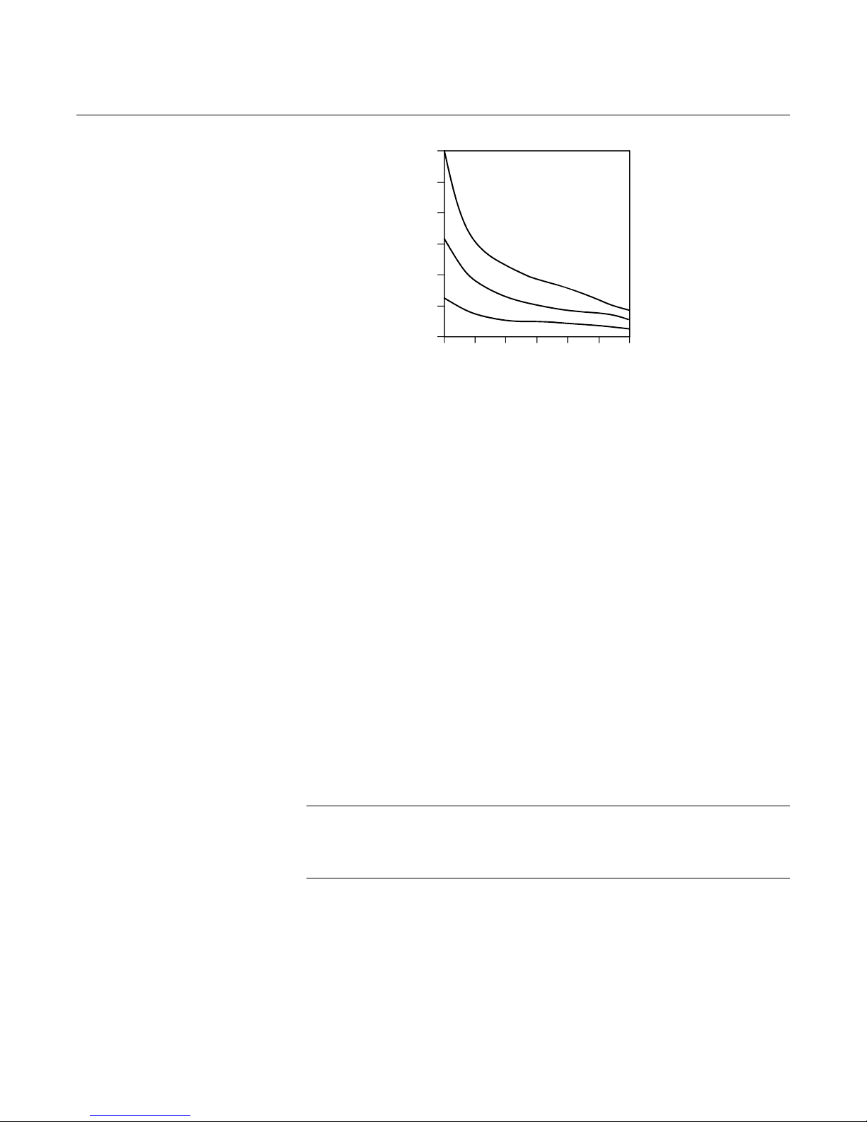
Figure 1-1 provides an example of the relationship between transmitter
housing temperature rise and extension length.
1-3
Rosemount 248
Reference Manual
00809-0100-4825, Rev BB
August 2005
Figure 1-1. Rosemount 248
Transmitter Connection Head
Temperature Rise vs. Extension
Length
60
50
40
30
20
10
0
Temperature Rise Above Ambient
8
1
5
5
°
4
C
0
P
75
°
2
5
0
r
C
100 125 150 175 200 225
o
c
e
s
P
r
oc
°
C
P
Extension Length (mm)
s
T
e
e
ss
r
o
c
e
mp
T
e
m
s
s
e
p
e
r
a
t
u
r
T
e
m
p
e
r
a
r
a
t
u
r
e
e
t
u
r
e
Example
The transmitter specification limit is 85 °C. If the ambient temperature is 55 °C
and the process temperature to be measured is 800 °C, the maximum
permissible connection head temperature rise is the transmitter specification
limit minus the ambient temperature (moves 85 to 55 °C), or 30 °C.
In this case, an extension of 100 mm meets this requirement, but 125 mm
provides a margin of 8 °C, thereby reducing any temperature effects in the
transmitter.
3044-0123A
RETURN OF MATERIALS To expedite the return process in North America, call the Emerson Process
Management National Response Center toll-free at 800-654-7768. This
center, available 24 hours a day, will assist you with any needed information
or materials.
The center will ask for the following information:
• Product model
• Serial numbers
• The last process material to which the product was exposed
The center will provide
• A Return Material Authorization (RMA) number
• Instructions and procedures that are necessary to return goods that
were exposed to hazardous substances
NOTE
If a hazardous substance is identified, a Material Safety Data Sheet (MSDS),
required by law to be available to people exposed to specific hazardous
substances, must be included with the returned materials.
Outside North America, contact a local Emerson Process Management
representative.
1-4

Reference Manual
00809-0100-4825, Rev BB
August 2005
Rosemount 248
Section 2 Installation
Safety Messages . . . . . . . . . . . . . . . . . . . . . . . . . . . . . . . . . page 2-1
Mounting . . . . . . . . . . . . . . . . . . . . . . . . . . . . . . . . . . . . . . . page 2-3
Installation . . . . . . . . . . . . . . . . . . . . . . . . . . . . . . . . . . . . . . page 2-4
Set the Switches . . . . . . . . . . . . . . . . . . . . . . . . . . . . . . . . . page 2-8
Wiring . . . . . . . . . . . . . . . . . . . . . . . . . . . . . . . . . . . . . . . . . . page 2-8
Power Supply . . . . . . . . . . . . . . . . . . . . . . . . . . . . . . . . . . . page 2-11
SAFETY MESSAGES Instructions and procedures in this section may require special precautions to
ensure the safety of the personnel performing the operations. Information that
potentially raises safety issues is indicated by a warning symbol ( ). Please
refer to the following safety messages before performing an operation
preceded by this symbol.
Warnings
Failure to follow these installation guidelines could result in death or
serious injury.
• Make sure only qualified personnel perform the installation.
Explosions could result in death or serious injury.
• Do not remove the connection head cover in explosive atmospheres when the
circuit is live.
• Before connecting a communicator in an explosive atmosphere, make sure the
instruments in the loop are installed in accordance with instrinsically safe or
non-incendive field wiring practices.
• Verify that the operating atmosphere of the transmitter is consistent with the
appropriate hazardous locations certifications.
• All connection head covers must be fully engaged to meet
explosion-proof requirements.
Process leaks could result in death or serious injury.
• Do not remove the thermowell while in operation.
• Install and tighten thermowells and sensors before applying pressure
Electrical shock could cause death or serious injury.
• Use extreme caution when making contact with the leads and terminals.
www.rosemount.com
Rosemount 248
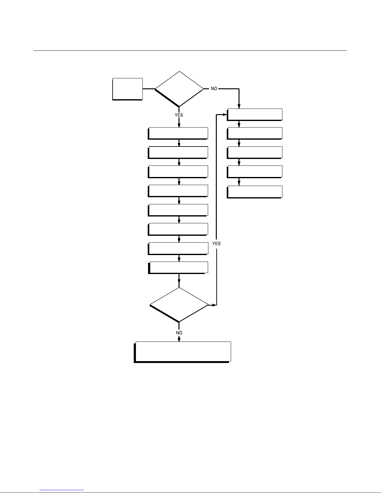
Figure 2-1. Installation Flowchart
Reference Manual
00809-0100-4825, Rev BB
August 2005
START
HERE
Bench
Calibration?
BASIC SETUP
Set Sensor Type
Set Number of Wires
Set Units
Set Range Values
Set Damping
VERIFY
FIELD INSTALL
Mount Transmitter
Wire Transmitter
Power Transmitter
FINISHED
Simulate Sensor Input
Within
Specifications?
Refer to Section 4: Operation and
Maintenance
244-244_03A
2-2

Reference Manual
00809-0100-4825, Rev BB
August 2005
Rosemount 248
MOUNTING Mount the transmitter at a high point in the conduit run to prevent moisture
from draining into the transmitter housing.
The Rosemount 248R installs directly to a wall or to a DIN rail.
The Rosemount 248H installs
• In a connection head or universal head mounted directly on a sensor
assembly
• Apart from a sensor assembly using a universal head
• To a DIN rail using an optional mounting clip
Mounting a Rosemount 248H to a DIN Rail
To attach a head mount transmitter to a DIN rail, assemble the appropriate rail
mounting kit (part number 00248-1601-0001) to the transmitter as shown in
Figure 2-2.
Figure 2-2. Assembling Rail Clip
Hardware to a Rosemount 248
Mounting
Hardware
Transmitter
Rail Clip
248_248-06A
2-3
Reference Manual
00809-0100-4825, Rev BB
Rosemount 248
August 2005
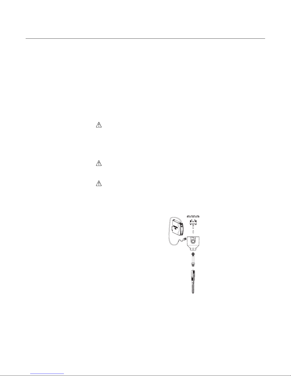
INSTALLATION The Rosemount 248 can be ordered assembled to a sensor and thermowell
or as a stand-alone unit. If ordered without the sensor assembly, use the
following guidelines when installing the transmitter with an integral sensor
assembly.
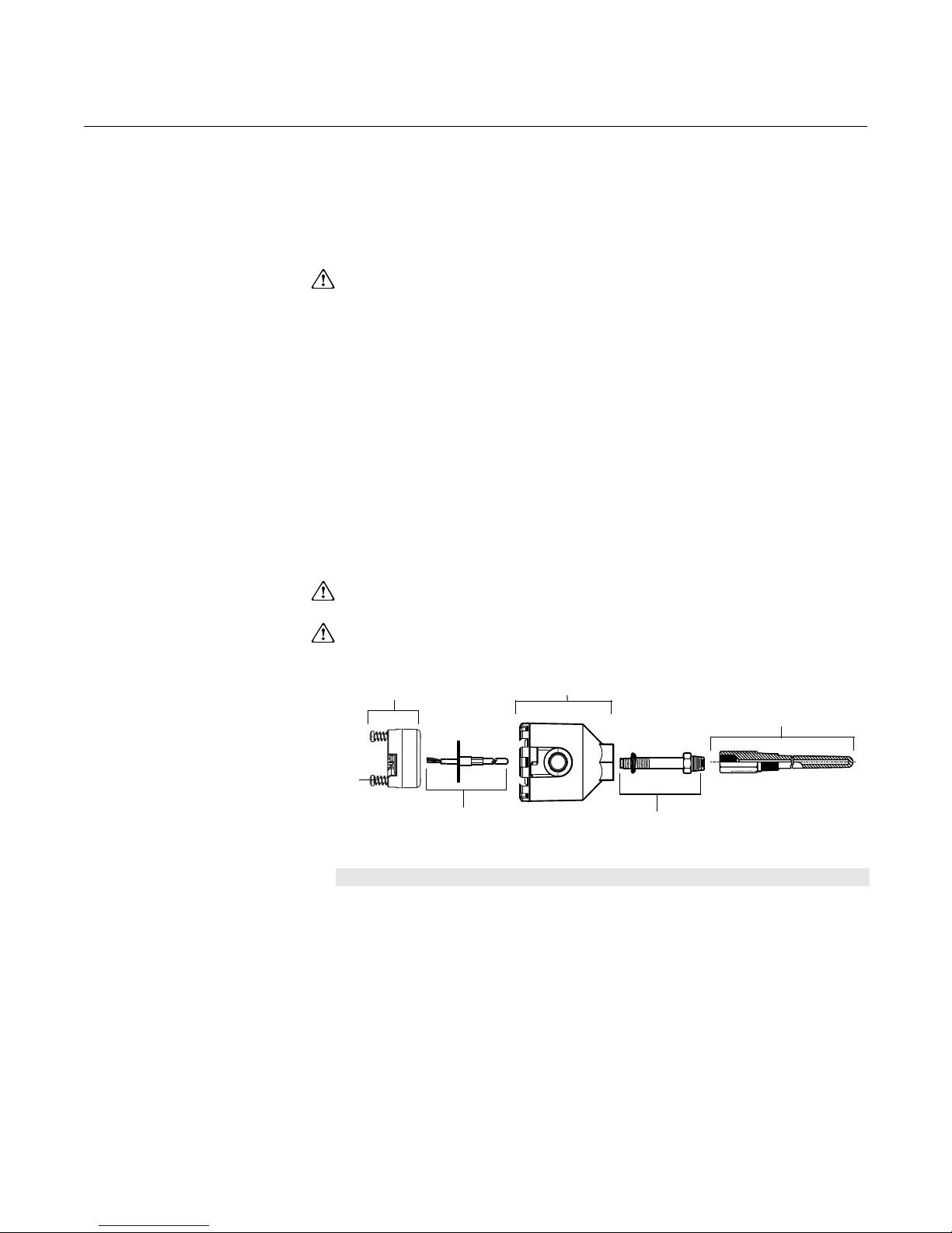
Typical European and
Asia Pacific Installation
Head Mount Transmitter with DIN Plate Style Sensor
1. Attach the thermowell to the pipe or process container wall. Install
and tighten the thermowell before applying process pressure.
2. Assemble the transmitter to the sensor. Push the transmitter
mounting screws through the sensor mounting plate and insert the
snap rings (optional) into the transmitter mounting screw groove.
3. Wire the sensor to the transmitter (see “Sensor Wiring Diagrams” on
page 2-10).
4. Insert the transmitter-sensor assembly into the connection head.
Thread the transmitter mounting screw into the connection head
mounting holes. Assemble the extension to the connection head.
Insert the assembly into the thermowell.
5. Slip the shielded cable though the cable gland
6. Attach a cable gland into the shielded cable.
7. Insert the shielded cable leads into the connection head through the
cable entry. Connect and tighten the cable gland.
8. Connect the shielded power cable leads to the transmitter power
terminals. Avoid contact with sensor leads and sensor connections.
9. Install and tighten the connection head cover. Enclosure covers must
be fully engaged to meet explosion-proof requirements.
A
B
C
2-4
D
E
A = Rosemount 248 Transmitter D = Transmitter Mounting Screws
B = Connection Head E = Integral Mount Sensor with Flying Leads
C = Thermowell F = Extension
F
3144-0433QIG
Reference Manual
00809-0100-4825, Rev BB
August 2005
Rosemount 248
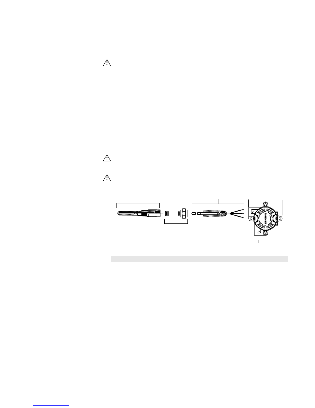
Typical North and South
American Installation
Head Mount Transmitter with Threaded Sensor
1. Attach the thermowell to the pipe or process container wall. Install
and tighten thermowells before applying process pressure.
2. Attach necessary extension nipples and adapters to the thermowell.
Seal the nipple and adapter threads with silicone tape.
3. Screw the sensor into the thermowell. Install drain seals if required for
severe environments or to satisfy code requirements.
4. Pull the sensor wiring leads through the universal head and
transmitter. Mount the transmitter in the universal head by threading
the transmitter mounting screws into the universal head mounting
holes.
5. Mount the transmitter-sensor assembly into the thermowell. Seal
adapter threads with silicone tape.
6. Install conduit for field wiring to the conduit entry of the universal
head. Seal conduit threads with silicone tape.
7. Pull the field wiring leads through the conduit into the universal head.
Attach the sensor and power leads to the transmitter. Avoid contact
with other terminals.
8. Install and tighten the universal head cover. Enclosure covers must
be fully engaged to meet explosion-proof requirements.
A
B
D
C
A = Threaded Thermowell D = Universal Head
B = Threaded Style Sensor E = Conduit Entry
C = Standard Extension
E
2-5
Rosemount 248
Reference Manual
00809-0100-4825, Rev BB
August 2005
Rail Mount Transmitter with Integral Mount Sensor
The least complicated assembly uses:
• an integral mount sensor with terminal block
• an integral DIN style connection head
• a standard extension
• a threaded thermowell
Refer to the Metric Product Data Sheet (document number 00813-0101-2654)
for complete sensor and mounting accessory information.
To complete the assembly, follow the procedure described below.
1. Attach the transmitter to a suitable rail or panel.
2. Attach the thermowell to the pipe or process container wall. Install
and tighten the thermowell before applying pressure.
3. Attach the sensor to the connection head and mount the entire
assembly to the thermowell.
4. Attach sufficient lengths of sensor lead wire to the sensor terminal
block.
5. Attach and tighten the connection head cover. Enclosure covers must
be fully engaged to meet explosion-proof requirements.
6. Run sensor lead wires from the sensor assembly to the transmitter.
7. Attach the sensor and power leads to the transmitter. Avoid contact
with leads and terminals.
Figure 2-3. Typical Rail Mount
Transmitter Mounting Configuration
Using Integral Mount Sensor
and Assembly
Rail Mount Transmitter
Sensor Leads
with Cable Gland
Integral Mount Sensor
with Terminal Block
Connection Head
Standard Extension
Threaded Thermowell
248-0000C04A
2-6

Reference Manual
00809-0100-4825, Rev BB
August 2005
Rosemount 248
Rail Mount Transmitter with Threaded Sensor
The least complicated assembly uses:
• a threaded sensor with flying heads
• a threaded sensor connection head
• a union and nipple extension assembly
• a threaded thermowell
Refer to Volume 1 of the Rosemount Sensors Product Data Sheet (document
number 00813-0100-2654) for complete sensor and mounting accessory
information.
To complete the assembly, follow the procedure described below.
1. Attach the transmitter to a suitable rail or panel.
2. Attach the thermowell to the pipe or process container wall. Install
and tighten the thermowell before applying pressure.
3. Attach necessary extension nipples and adapters. Seal the nipple
and adapter threads with silicone tape.
4. Screw the sensor into the thermowell. Install drain seals if required for
severe environments or to satisfy code requirements.
5. Screw the connection head to the sensor.
6. Attach the sensor lead wires to the connection head terminals.
7. Attach additional sensor lead wires from the connection head to the
transmitter.
8. Attach and tighten the connection head cover. Enclosure covers must
be fully engaged to meet explosion-proof requirements.
9. Attach the sensor and power leads to the transmitter. Avoid contact
with leads and terminals.
Figure 2-4. Typical Rail Mount
Transmitter Mounting Configuration
Using Threaded Style Sensor
and Assembly
Rail Mount
Transmitter
Threaded Sensor
Connection Head
Threaded
Style Sensor
Standard
Extension
Threaded
Thermowell
248-0000A04B
2-7

Rosemount 248
Reference Manual
00809-0100-4825, Rev BB
August 2005
MULTICHANNEL
INSTALLATIONS
Several transmitters can be connected to a single master power supply, as
shown in Figure 2-5. In this case, the system may be grounded only at the
negative power supply terminal. In multichannel installations where several
transmitters depend on one power supply and the loss of all transmitters
would cause operational problems, consider an uninterrupted power supply or
a back-up battery. The diodes shown in Figure 2-5 prevent unwanted
charging or discharging of the back-up battery.
Figure 2-5. Multichannel
Installations
R
Transmitter
No. 1
Transmitter
No. 2
Between 250 Ω and 1100 Ω if no load resistor.
R
R
Lead
Lead
Lead
Readout or
Controller No. 1
Readout or
Controller No. 2
Backup
Battery
dc
Power
Supply
To Additional
Transmitters
SET THE SWITCHES
Failure Mode As part of normal operation, each transmitter continuously monitors its own
performance. This automatic diagnostics routine is a timed series of checks
repeated continuously. If diagnostics detect an input sensor failure or a failure
in the transmitter electronics, the transmitter drives its output to low or high
alarm depending on the failure mode configuration. (Saturation levels are
3.90 mA for standard configuration (3.8 mA if configured for NAMURcompliant operation) on the low end and 20.5 mA for standard or NAMURcompliant configuration on the high end, if the sensor temperature is outside
of range limits.) These values are also custom configurable by the factory or
using the 375 Field Communicator or AMS. See “Alarm and Saturation” on
page 3-11 for instructions on how to change the alarm and saturation levels
with the 375 Field Communicator.
3044-0131A
WIRING All power to the transmitter is supplied over the signal wiring. Use ordinary
2-8
NOTE
Microprocessor failures cause high alarm regardless of alarm direction (high
or low) choice.
The values to which the transmitter drives its output in failure mode depend
on whether it is configured to standard, NAMUR-compliant, or custom
operation. See “Software Detected Failure Mode” on page A-2 for standard
and NAMUR-compliant operation parameters.
copper wire of sufficient size to ensure that the voltage across the transmitter
power terminals does not drop below 12.0 V dc. Verify that the operating
atmosphere of the transmitter is consistent with the appropriate hazardous
locations certifications. Use extreme caution when making contact with the
leads and terminals.

Reference Manual
00809-0100-4825, Rev BB
August 2005
Rosemount 248
If the sensor is installed in a high-voltage environment and a fault condition or
installation error occurs, the sensor leads and transmitter terminals could
carry lethal voltages. Use extreme caution when making contact with the
leads and terminals.
NOTE
Do not apply high voltage (e.g., ac line voltage) to the transmitter terminals.
Abnormally high voltage can damage the unit. (Sensor and transmitter power
terminals are rated to 42.4 V dc.) Use extreme caution when making contact
with the leads and terminals.
For multichannel installations, see above. The transmitters will accept inputs
from a variety of RTD and thermocouple types. Refer to Figure 2-7 on
page 2-10 when making sensor connections.
Use the following steps to wire the transmitter:
1. Remove the terminal block cover (if applicable).
2. Connect the positive power lead to the “+” terminal. Connect the
negative power lead to the “–” terminal (see Figure 2-6). Use extreme
caution when making contact with the leads and terminals.
3. Tighten the terminal screws.
4. Reattach and tighten the cover (if applicable). All connection head
covers must be fully engaged to meet explosion-proof requirements
5. Apply power (see “Power Supply”).
.
Figure 2-6. Rosemount 248
Wiring
Power, Communication and
Sensors Terminals
33 (1.3)
44.0 (1.7)
12.9 (0.51)
24.5 (0.97)
Note: Signal loop may be grounded at any single point or left ungrounded.
Note: A 375 Field Communicator may be connected at any termination point in the signal loop. The
signal loop must have between 250 and 1100 ohms load for communications.
Connecting a Communicator to a Transmitter Loop
250 ≤ RL ≤ 110 0
HART Communicator
Power
Supply
Sensor Connections The Rosemount 248 is compatible with a number of RTD and thermocouple
sensor types. Figure 2-7 shows the correct input connections to the sensor
terminals on the transmitter. To ensure a proper sensor connection, anchor
the sensor lead wires into the appropriate compression terminals and tighten
the screws. Use extreme caution when making contact with the leads and
terminals.
2-9

Rosemount 248
Figure 2-7. Sensor Wiring
Diagrams
Reference Manual
00809-0100-4825, Rev BB
August 2005
Rosemount 248 Sensor Connections Diagram
1
2-wire
RTD and
* Emerson Process Management provides 4-wire sensors for all single element RTDs. Use these
RTDs in 3-wire configurations by leaving the unneeded leads disconnected and insulated with electrical
tape.
3-wire*
RTD
and
1234234 12 34 1234
4-wire RTD
and
T/C
and mV
Thermocouple or Millivolt Inputs
The thermocouple can be connected directly to the transmitter. Use
appropriate thermocouple extension wire if mounting the transmitter remotely
from the sensor. Make millivolt input connections with copper wire. Use
shielding for long runs of wire.
RTD or Ohm Inputs
The transmitters will accept a variety of RTD configurations, including 2-wire,
3-wire and 4-wire designs. If the transmitter is mounted remotely from a
3-wire or 4-wire RTD, it will operate within specifications, without recalibration,
for lead wire resistances of up to 60 ohms per lead (equivalent to 6,000 feet of
20 AWG wire). In this case, the leads between the RTD and transmitter
should be shielded. If using only two leads, both RTD leads are in series with
the sensor element, so significant errors can occur if the lead lengths exceed
three feet of 20 AWG wire (approximately 0.05 °C/ft). For longer runs, attach a
third or fourth lead as described above.
Sensor Lead Wire Resistance Effect– RTD Input
When using a 4-wire RTD, the effect of lead resistance is eliminated and
has no impact on accuracy. However, a 3-wire sensor will not fully cancel
lead resistance error because it cannot compensate for imbalances in
resistance between the lead wires. Using the same type of wire on all
three lead wires will make a 3-wire RTD installation as accurate as
possible. A 2-wire sensor will produce the largest error because it directly
adds the lead wire resistance to the sensor resistance. For 2- and 3-wire
RTDs, an additional lead wire resistance error is induced with ambient
temperature variations. The table and the examples shown below help
quantify these errors.
248-0000B01C
Table 2-1. Examples of
Approximate Basic Error
2-10
Sensor Input Approximate Basic Error
4-wire RTD None (independent of lead wire resistance)
3-wire RTD ± 1.0 Ω in reading per ohm of unbalanced lead wire resistance
2-wire RTD 1.0
(Unbalanced lead wire resistance = maximum imbalance between
any two leads.)
Ω in reading per ohm of lead wire resistance

Reference Manual
00809-0100-4825, Rev BB
August 2005
Rosemount 248
Examples of Approximate Lead Wire Resistance Effect Calculations
Given:
Total cable length: 150 m
Imbalance of the lead wires at 20 °C: 0.5 Ω
Resistance/length (18 AWG Cu): 0.025 Ω/m °C
Temperature coefficient of Cu (αCu): 0.039 Ω/Ω °C
Temperature coefficient of Pt(α
Change in Ambient Temperature (ΔT
RTD Resistance at 0 °C (R
• Pt100 4-wire RTD: No lead wire resistance effect.
• Pt100 3-wire RTD:
Imbalance of Lead Wires
Basic Error
Error due to amb. temp. variation
------------------------------------------------------------------=
Lead wire imbalance seen by the transmitter = 0.5
Basic error
---------------------------------------------------------------------------------- 1.3 °C==
0.00385 Ω / Ω °C()100 Ω()×
): 0.00385 Ω/Ω °C
Pt
): 100 Ω (for Pt 100 RTD)
o
α
×()
PtRo
): 25 °C
amb
()ΔT
()× Imbalance of Lead Wires()×
α
Cu
-------------------------------------------------------------------------------------------------------------------------=
amb
()Ro()×
α
Pt
Ω
0.5 Ω
Error due to amb. temp. var. of 25 °C±
0.0039 Ω / Ω °C()25 ° C()× 0.5 Ω()×
------------------------------------------------------------------------------------------------------- 0.13°·C±==
0.00385 Ω / Ω °C()100Ω()×
• Pt100 2-wire RTD:
Basic Error
Error due to amb. temp. variation
Lead Wire Resistance
----------------------------------------------------------=
α
×()
PtRo
α
()ΔT
Cu
-----------------------------------------------------------------------------------------------------------------=
()× Lead Wire Resistance()×
amb
()Ro()×
α
Pt
Lead wire resistance seen by the transmitter = 150 m × 2 wires ×
0.025
Ω/m = 7.5 Ω
Basic error
Error due to amb. temp. var. of 25 °C±
0.0039 Ω / Ω °C()25 ° C()× 7.5 Ω()×
------------------------------------------------------------------------------------------------------- 1.9 °C±==
---------------------------------------------------------------------------------- 19.5 °C==
0.00385 Ω / Ω °C()100 Ω()×
0.00385 Ω / Ω °C()100Ω()×
7.5 Ω
POWER SUPPLY To communicate with a transmitter, an 18.1 V dc minimum power supply is
required. The power supplied to the transmitter should not drop below the
transmitter lift-off voltage (see Figure 2-8). If the power drops below the lift-off
voltage while the transmitter is being configured, the transmitter may interpret
the configuration information incorrectly.
The dc power supply should provide power with less than 2 percent ripple.
The total resistance load is the sum of the resistance of the signal leads and
the load resistance of any controller, indicator, or related pieces of equipment
in the loop. Note that the resistance of intrinsic safety barriers, if used, must
be included.
2-11

Rosemount 248
Reference Manual
00809-0100-4825, Rev BB
August 2005
Figure 2-8. Load Limits
Maximum Load = 40.8 x (Supply Voltage – 12.0)
1322
1100
1000
750
500
Load (Ohms)
250
0
4–20 mA dc
Operating
Region
10
20 30 40 42.4
12.0
Supply Voltage (V dc)
Surges/Transients The transmitter will withstand electrical transients of the energy level
encountered in static discharges or induced switching transients. However,
high-energy transients, such as those induced in wiring from nearby lightning
strikes, welding, heavy electrical equipment, or switching gears, can damage
both the transmitter and the sensor. To protect against high-energy transients,
install the transmitter into a suitable connection head with the Rosemount 470
Transient Protector. Refer to the Rosemount 470 Transient Protector Product
Data Sheet (document number 00813-0100-4191) for more information.
Ground the Transmitter The transmitter will operate with the current signal loop either floating or
grounded. However, the extra noise in floating systems affects many types of
readout devices. If the signal appears noisy or erratic, grounding the current
signal loop at a single point may solve the problem. The best place to ground
the loop is at the negative terminal of the power supply. Do not ground the
current signal loop at more than one point.
644_08A
The transmitter is electrically isolated to 500 V ac rms (707 V dc), so the input
circuit may also be grounded at any single point. When using a grounded
thermocouple, the grounded junction serves as this point.
NOTE
Do not ground the signal wire at both ends.
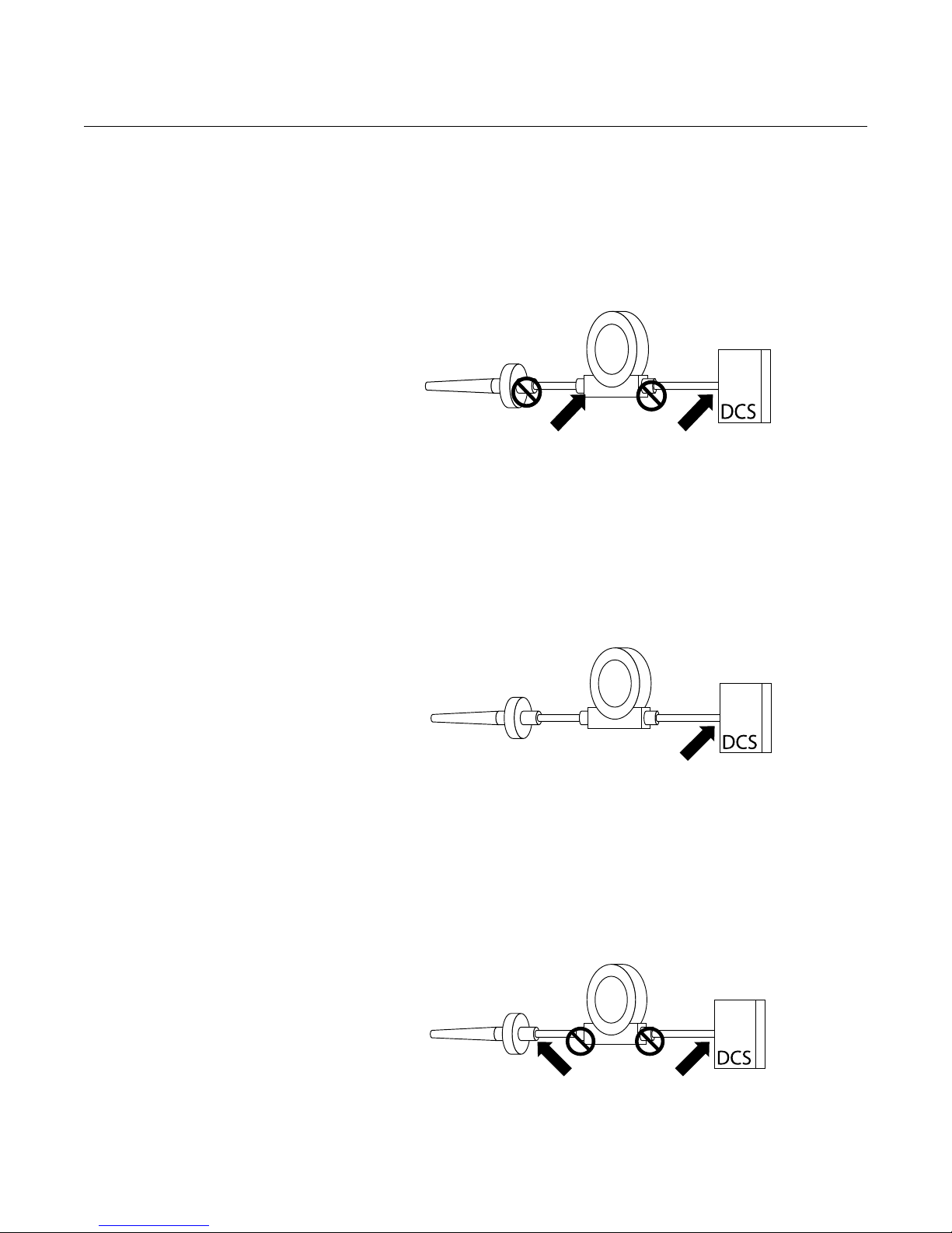
Ungrounded Thermocouple, mV, and RTD/Ohm Inputs
Each process installation has different requirements for grounding. Use the
grounding options recommended by the facility for the specific sensor type, or
begin with grounding Option 1 (the most common).
2-12
Reference Manual
00809-0100-4825, Rev BB
August 2005
Rosemount 248
Option 1:
1. Connect sensor wiring shield to the transmitter housing (only if the
housing is grounded).
2. Ensure the sensor shield is electrically isolated from surrounding
fixtures that may be grounded.
3. Ground signal wiring shield at the power supply end.
Transmitter
Sensor Wires
Shield ground point
Option 2 (for ungrounded housing):
1. Connect signal wiring shield to the sensor wiring shield.
2. Ensure the two shields are tied together and electrically isolated from
the transmitter housing.
3. Ground shield at the power supply end only.
4. Ensure that the sensor shield is electrically isolated from the
surrounding grounded fixtures.
4–20 mA loop
Transmitter
4–20 mA loop
Sensor Wires
Shield ground point
Connect shields together, electrically isolated from the transmitter
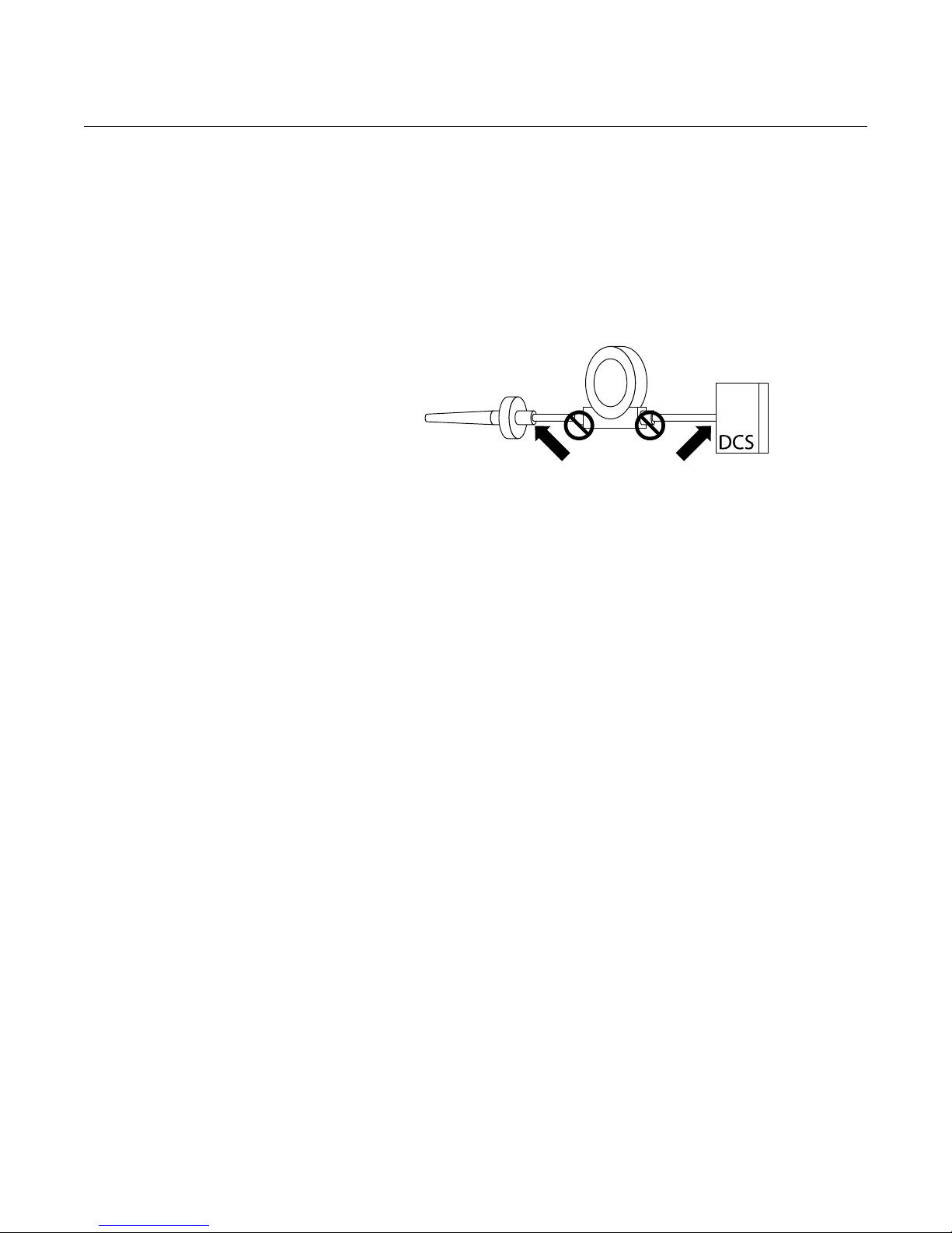
Option 3:
1. Ground sensor wiring shield at the sensor, if possible.
2. Ensure that the sensor wiring and signal wiring shields are electrically
isolated from the transmitter housing.
3. Do not connect the signal wiring shield to the sensor wiring shield.
4. Ground signal wiring shield at the power supply end.
Transmitter
4–20 mA loopSensor Wires
Shield ground point
2-13
Rosemount 248
Reference Manual
00809-0100-4825, Rev BB
August 2005
Grounded Thermocouple Inputs
Option 4
1. Ground sensor wiring shield at the sensor.
2. Ensure that the sensor wiring and signal wiring shields are electrically
isolated from the transmitter housing.
3. Do not connect the signal wiring shield to the sensor wiring shield.
4. Ground signal wiring shield at the power supply end.
Transmitter
Sensor Wires
Shield ground point
4–20 mA loop
2-14
 Loading...