

Page 1
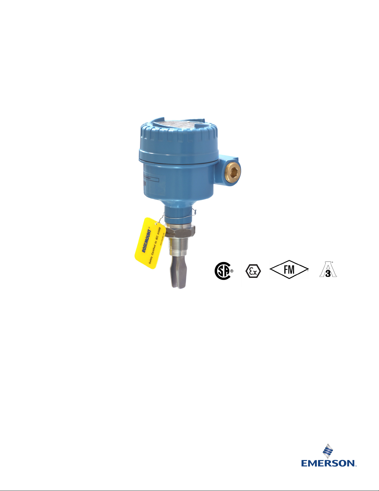
Rosemount™ 2120 Level Switch
Vibrating Fork
Product Data Sheet
December 2017
00813-0100-4030, Rev HC
Designed for operation in process
temperatures of –40 to 302 °F (–40 to 150 °C)
Electronic self-checking and condition
monitoring
Increased safety, SIL2-certified to IEC 61508
as required by IEC 61511 and SIL3 capable
Adjustable switching delay for turbulent or
splashing applications
“Fast drip” fork design gives a quicker response
time, especially with viscous liquids
General area, explosion-proof/flameproof, and
intrinsically safe options
Hygienically certified to 3-A
and complies with FDA and ASME-BPE
®
and EHEDG,
Page 2
Rosemount 2120 Level Switch
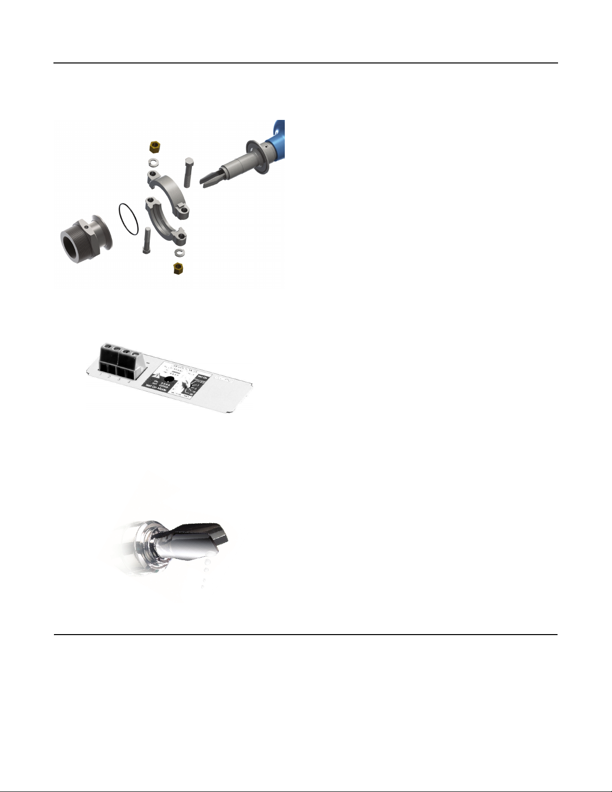
‘Fast drip’ forks
There is a variety of plug-in electronics options, with
each having an adjustable mode and switching delay
(see “Electrical connections” on page 12)
The Quick Release kit is a new optional set of accessories.
It makes inspection, proof-testing, and servicing easier than ever
(see Table 2 on page 9 for accessories)
Overview of the Rosemount 2120 Level Switch
Measurement principle
The Rosemount 2120 is designed using the principle of a tuning fork.
A piezo-electric crystal oscillates the forks at their natural frequency.
Changes to this frequency are continuously monitored. The frequency
of the vibrating fork sensor changes depending on the medium in
which it is immersed. The denser the liquid, the lower the frequency.
When used as a low level alarm, the liquid in the tank or pipe drains
down past the fork, causing a change of natural frequency that is
detected by the electronics and switches the output state.
When the Rosemount 2120 is used as a high level alarm, the liquid
rises in the tank or pipe, making contact with the fork which then
causes the output state to switch.
Key features and benefits
December 2017
Function virtually unaffected by flow, bubbles, turbulence, foam,
vibration, solids content, coating products, liquid properties, and
product variations
The Rosemount 2120 is designed for operation in process
temperatures from –40 to 302 °F (–40 to 150 °C)
A ‘heartbeat’ LED indicates its operating state. The LED also flashes
when the switch output is ‘off’ and is constantly lit when 'on'
Adjustable switching delay prevents false switching in turbulent or
splashing applications
‘Fast drip’ fork design gives quicker response time, especially with
viscous liquids. Rapid wet-to-dry and dry-to-wet time setting for
highly responsive switching
Fork shape is optimized for polishing to meet hygienic
requirements. Mechanical- and electro-polishing options.
Magnetic test point makes functional test easy
No moving parts or crevices for virtually no maintenance
Contents
Overview of the Rosemount 2120 Level Switch . . page 2 Specifications . . . . . . . . . . . . . . . . . . . . . . . . . . . .page 10
Ordering Information . . . . . . . . . . . . . . . . . . . . . . . . page 4 Product Certifications . . . . . . . . . . . . . . . . . . . . .page 14
Spare Parts and Accessories . . . . . . . . . . . . . . . . . . . page 9 Dimensional Drawings . . . . . . . . . . . . . . . . . . . .page 16
2 Emerson.com/Rosemount
Page 3
December 2017
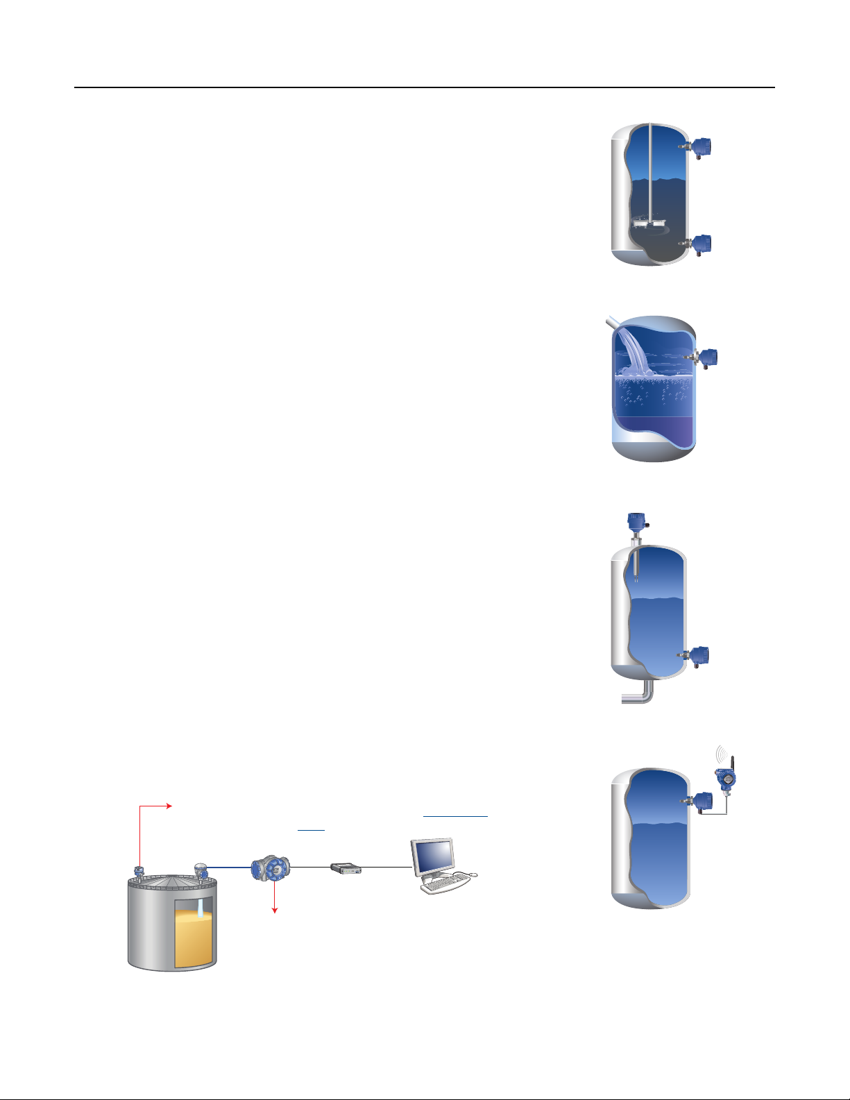
High and low level alarm
High-temperature applications
Pump control / limit detection
Wireless applications using a
Rosemount 702 Discrete Transmitter
In tank gauging systems, a Rosemount 2120
high level alarm switch can be used as an
alternative to a radar level gauge. See the
Rosemount Tank Gauging Product Data
Sheet for additional information.
Point Level Alarm
Rosemount
2120
Rosemount
5900S
Level
High level alarm: two separate
and configurable relay outputs
Fit and forget
Once installed, the Rosemount 2120 is ready to go.
It needs no calibration and requires minimum installation
The ‘heartbeat’ LED gives an instant visual indication that the unit is operational
Functional testing of the instrument and system is easy with a magnetic test point
You can install, and forget it
Superior performance
The Rosemount 2120 is a popular choice for high and low level alarm and pump
control duties for its simplicity, ease of use, and reliability
Functionality is virtually unaffected by flow, turbulence, bubbles, foam, or vibration
The ‘fast drip’ design allows the liquid to be quickly drawn away from the fork tip
when mounted horizontally, making the Rosemount 2120 quicker and more
responsive in high density or viscous liquid applications
Rosemount 2120 Level Switch
With a user-selectable time delay feature, the risk of false switching is minimized in
turbulent or splashing applications
Applications
Overfill protection
High and low point level alarms
Pump control or limit detection
Run dry or pump protection
Hygienic applications
High-temperature applications
Wireless applications
r
a
d
a
R
k
n
a
T
t
n
u
o
m
e
s
o
R
f
f
O
-
M
R
E
T
n
O
i
H
Rx
-
N
I
Tx
A
G
o
L
USB
RS-232
Ext. pwr
0
8
1
2
M
B
F
3Emerson.com/Rosemount
Page 4
Rosemount 2120 Level Switch
December 2017
Ordering Information
Specification and selection of product materials, options, or components must be made by the purchaser of the equipment.
See page 10 for more information on Material Selection.
Table 1. Rosemount 2120 Ordering Information
The starred options (★) represent the most common options and should be selected for best delivery. The non-starred offerings are
subject to additional delivery lead time.
Model Product description
2120 Vibrating Fork Liquid Level Switch / –40…302 °F (–40...150 °C)
Materials of construction: process connection/fork
D 316/316L Stainless Steel (1.4401/1.4404) dual certified
(1)
F
C Alloy C (UNS N10002), Alloy C-276 (UNS N10276), Solid
ECTFE copolymer, coated 316/316L SST (1.4401/1.4404)
Process connection size / type
0A
0B
0D
1A 1-in. BSPT (R) Thread
1B 1-in. BSPP (G) Thread
1D 1-in. NPT Thread
1P 1-in. BSPP (G), O-ring
5R 11/2-in. (38 mm) Tri Clamp
2R 2-in. (51 mm) Tri Clamp
1G 1-in. ASME B16.5 Class 150 Raised Face (RF) Flange
1H 1-in. ASME B16.5 Class 300 Raised Face (RF) Flange
1J 1-in. ASME B16.5 Class 600 Raised Face (RF) Flange
5G 11/2-in. ASME B16.5 Class 150 Raised Face (RF) Flange
5H 11/2-in. ASME B16.5 Class 300 Raised Face (RF) Flange
2G 2-in. ASME B16.5 Class 150 Raised Face (RF) Flange
2H 2-in. ASME B16.5 Class 300 Raised Face (RF) Flange
3G 3-in. ASME B16.5 Class 150 Raised Face (RF) Flange
3H 3-in. ASME B16.5 Class 300 Raised Face (RF) Flange
4G 4-in. ASME B16.5 Class 150 Raised Face (RF) Flange
4H 4-in. ASME B16.5 Class 300 Raised Face (RF) Flange
1K DN25, EN1092 PN 10/16 Flange
1L DN25, EN1092 PN 25/40 Flange
1M DN25, EN1092 PN 63 Flange
1N DN25, EN1092 PN 100 Flange
5K DN40, EN1092 PN 10/16 Flange
5L DN40, EN1092 PN 25/40 Flange
3
/4-in. BSPT (R) Thread
3
/4-in. BSPP (G) Thread
3
/4-in. NPT Thread
★
★
★
★
★
★
★
★
★
★
★
★
★
★
★
★
★
★
★
★
★
★
★
★
★
★
★
4
Emerson.com/Rosemount
Page 5

December 2017
Rosemount 2120 Level Switch
Table 1. Rosemount 2120 Ordering Information
The starred options (★) represent the most common options and should be selected for best delivery. The non-starred offerings are
subject to additional delivery lead time.
2K DN50, EN1092 PN 10/16 Flange
2L DN50, EN1092 PN 25/40 Flange
7K DN65, EN1092 PN 10/16 Flange
7L DN65, EN1092 PN 25/40 Flange
3K DN80, EN1092 PN 10/16 Flange
3L DN80, EN1092 PN 25/40 Flange
4K DN100, EN1092 PN 10/16 Flange
4L DN100, EN1092 PN 25/40 Flange
5J 11/2-in. ASME B16.5 Class 600 Raised Face (RF) Flange
2J 2-in. ASME B16.5 Class 600 Raised Face (RF) Flange
3J 3-in. ASME B16.5 Class 600 Raised Face (RF) Flange
4J 4-in. ASME B16.5 Class 600 Raised Face (RF) Flange
5M DN40, EN1092 PN 63 Flange
5N DN40, EN1092 PN 100 Flange
2M DN50, EN1092 PN 63 Flange
2N DN50, EN1092 PN 100 Flange
7M DN65, EN1092 PN 63 Flange
7N DN65, EN1092 PN 100 Flange
3M DN80, EN1092 PN 63 Flange
3N DN80, EN1092 PN 100 Flange
4M DN100, EN1092 PN 63 Flange
4N DN100, EN1092 PN 100 Flange
SA 25A, 10K, JIS B2220 Flange
SB 25A, 20K, JIS B2220 Flange
TA 40A, 10K, JIS B2220 Flange
TB 40A, 20K, JIS B2220 Flange
UA 50A, 10K, JIS B2220 Flange
UB 50A, 20K, JIS B2220 Flange
VA 80A, 10K, JIS B2220 Flange
VB 80A, 20K, JIS B2220 Flange
ZA 100A, 10K, JIS B2220 Flange
ZB 100A, 20K, JIS B2220 Flange
(2)
XX
Customer Specific
★
★
★
★
★
★
★
★
Emerson.com/Rosemount
5
Page 6
Rosemount 2120 Level Switch
December 2017
Table 1. Rosemount 2120 Ordering Information
The starred options (★) represent the most common options and should be selected for best delivery. The non-starred offerings are
subject to additional delivery lead time.
Electronic type
Available certifications
T Direct load switching (Mains 2-wire) 20 to 264 Vac 50/60Hz, 20 to 60 Vdc NA, E1, E5, E6, E7, EM, G5, G6
G PNP/PLC (3-wire) 20 to 60 Vdc NA, E1, E5, E6, E7, EM, G5, G6
V Relay DPCO, 20 to 264 Vac 50/60Hz, 20 to 60 Vdc NA, E1, E5, E6, E7, EM, G5, G6
E Relay DPCO, 9...30 Vdc E5 and G5
K NAMUR All
H 8/16 mA All
Surface finish
Available
connections
Available
housings
1 Standard surface finish All All
(3)
2
(4)
3
(4)
4
(4)
7
(4)
8
Product certifications
NA
G5
G6
Hand polished (Ra < 0.4 μm) Tri Clamp only All
Ra < 0.76 μm, hygienically approved Tri Clamp only A, X
Electro-polished to 0.76 μm, hygienically approved Tri Clamp only A, X
Mechanically-polished to Ra < 0.1 μm, hygienically approved Tri Clamp only A, X
Electro-polished to Ra < 0.38 μm, hygienically approved Tri Clamp only A, X
Electronic
types allowed
(5)
No Hazardous Locations Certifications All except option E All
(6)
FM Ordinary Locations (unclassified, safe area) All Y, T
(7)
CSA Ordinary Locations (unclassified, safe area) All except option E Y, T
Available
housings
E1 ATEX Flameproof All except option E X, S
(6)
E5
E6
(7)
FM Explosion-proof All Y, T
CSA Explosion-proof All except option E Y, T
E7 IECEx Explosion-proof All except option E X, S
EM Technical Regulation Customs Union (EAC), Flameproof All except option E X, S
I1 ATEX Intrinsic Safety K, H All
I5 FM Intrinsic Safety K, H All
I6 CSA Intrinsically Safe K, H All
I7 IECEx Intrinsic Safety K, H All
IM Technical Regulation Customs Union (EAC), Intrinsic. Safe K, H All
★
★
★
★
★
★
★
★
★
★
★
★
★
★
★
★
★
★
★
★
★
★
★
★
★
Housing
Available certifications
A Glass Filled Nylon, M20 conduits/cable threads NA, I1, I5, I6, and I7
D Glass Filled Nylon, 1/2-in. ANPT conduits/cable threads NA, I1, I5, I6, and I7
X Aluminum Alloy, M20 conduits/cable threads All except G5, G6, E5, E6
Y Aluminum Alloy, 3/4-in. ANPT conduits/cable threads All except E1, E7, and EM
S Stainless Steel, M20 conduits/cable threads All except G5, G6, E5, E6
T Stainless Steel 3/4-in. ANPT conduits/cable threads All except E1, E7, and EM
6
Emerson.com/Rosemount
★
★
★
★
★
★
Page 7
December 2017
Rosemount 2120 Level Switch
Table 1. Rosemount 2120 Ordering Information
The starred options (★) represent the most common options and should be selected for best delivery. The non-starred offerings are
subject to additional delivery lead time.
Fork length
Available connection
A Standard length 1.7 in. (44 mm) All except flanged options
(8)
H
(9)
E
(9)
M
Standard length flange 4.0 in. (102 mm) All flanged options
Extended, customer specified length in tenths of inches All except 1-in. BSPP O-ring (1P)
Extended, customer specified length in millimeters All except 1-in. BSPP O-ring (1P)
Specific extended fork length
0000 Factory default length (only if Fork Length A or H is selected)
(9)
XXXX
Specific customer specified length in tenths of inches or millimeters (XXX.X inches or XXXX mm)
Typical Model Number: 2120 D 0A K 1 I1 A 0000
Options (include with the selected model number)
Calibration data certification
Q4 Certificate of functional test
Material traceability certification
(8)(10)
Q8 Material traceability certification per EN 10204 3.1
Material certification
(8)(10)
Q15 NACE® MR0175 / ISO 15156
Q25 NACE MR0103
Safety certification
(11)
★
★
★
★
★
★
★
★
★
★
QS Prior-use certificate of FMEDA Data
(12)
QT
Special procedures
Safety certificate to IEC61508
(13)
P1 Hydrostatic testing with certificate
Hygienic certifications
(14)
QA 3-A certificate
QE EHEDG certificate
ASME-BPE statement
(14)
QB ASME-BPE statement
Food Drug Administration statement
(14)
QH FDA statement
Surface finish certification
(14)
Q16 Surface finish certificate
Example of options included with the model number: 2120 D 0A K 1 I1 A 0000 Q8
1. ECTFE copolymer coating is only available for a flanged Rosemount 2120 but excludes 1-in./DN25/25A flanges.
Flanges are dual certified 316 and 316L Stainless Steel (1.4401 and 1.4404).
★
★
★
★
★
★
★
★
Emerson.com/Rosemount
7
Page 8

Rosemount 2120 Level Switch
2. Other process connections available upon request.
3. Hand-polished for hygienic connections to better than 0.4 μm Ra such that there are no pits, folds, crevices o r cracks discernible to the naked eye (i.e. no features
larger than 75 micrometers based on resolving 1/60 degree at a distance of 250 mm).
4. Not available for explosion-proof or flameproof product certifications.
5. Includes the Technical Regulation Customs Union (EAC) ordinary location mark.
6. See “Product Certifications” on page 14. E5 includes G5 requirements. G5 is for use in unclassified, safe area locations only.
7. See “Product Certifications” on page 14. E6 includes G6 requirements. G6 is for use in unclassified, safe area locations only.
8. Not available for hand polished wet side.
9. Minimum length available for
and for Tri Clamp, it is 4.1 in. (105 mm). Maximum length is 157.5 in. (4000 mm), except for ECTFE copolymer coating and polished process where the maximum
length is 59.1 in. (1500 mm) and 39.4 in. (1000 mm) respectively. Examples: Code E1181 is 118.1 inches. Code M3000 is 3000 millimeters.
10. Only available for process-wetted parts.
11. Not available for Direct Load or Relay (option code E) switching electronics.
12. Not available with Relay (option code V) switching electronics.
13. Option limited to units with extended lengths up to 59.1-in. (1500 mm). Option is not available for ECTFE coating.
14. Available only for a Rosemount 2120 with a Tri Clamp fitting, Product Certification code NA, G*, or I*, and Surface Finish code 3, 4, 7, or 8.
3
/4-in. threaded connection is 3.8 in. (95 mm); for 1-in. threaded, it is 3.7 in. (94 mm); for flanged, it is 3.5 in. (89 mm);
December 2017
Safety Integrity Level (SIL) certification option
The Rosemount 2120 has been independently certified to IEC 61508 as required by IEC 61511. Certification was conducted by
Exida. If required, add “QT” to the end of the model code. For example, 2120 D 0A K E1 X A0000 QT.
(Note that you can have one or more OPTIONS codes at the end).
Visit the Rosemount 2120 web page for additional information.
Overfill approval option
The Rosemount 2120 has been TÜV-tested and approved for overfill protection according to the German DIBt/WHG regulations.
This option is not selectable in the ordering information table. If required, add “R2259” to the end of the model code.
For example, 2120 D 0A K E1 X A0000 R2259. (Note that you can have one or more OPTIONS codes at the end).
8
Emerson.com/Rosemount
Page 9

December 2017
Rosemount 2120 Level Switch
Spare Parts and Accessories
Table 2. Spare Parts and Accessories
Specification and selection of product materials, options, or components must be made by the purchaser of the equipment.
See page 10 for more information on Material Selection.
Spares and accessories
(1)(2)
02100-1000-0001 Seal for 1-in. BSPP (G1A). Material: Non-asbestos BS7531 grade X carbon fiber with rubber binder
02100-1040-0001 Seal for 3/4-in. BSPP (G3/4A). Material: Non-asbestos BS7531 grade X carbon fiber with rubber binder
02100-1010-0001 Adaptor boss 1-in. BSPP to 11/2-in. (38mm) Tri-Clamp. Material: 316 SST fitting. FPM/FKM O-ring
02100-1020-0001
(3)
2-in. (51 mm) Tri Clamp kit (vessel fitting, clamp ring, and seal). Material: 316 SST, NBR Nitrile
02100-1030-0001 Telescopic test magnet
02120-7000-0001
02120-7000-0002
02120-7000-0003
02120-7000-0004
02120-7000-0005
02120-7000-0007
02100-1060-0001
1. Check the Electronic Type and Product Certification sections in Table 1 on page 4 for availability conditions.
2. Intrinsically Safe (IS) approved cassettes can only be replaced with the same type of IS cassette. Non-IS cassette types can be interchanged with other non-IS
cassettes, but the new label must be fitted and the original part number transferred to the new label.
3. This is not approved to be used with a 3-A or EHEDG approved products and is not assessed for use with FDA or ASME-BPE compliant products.
4. This replacement cassette is for versions of the Rosemount 2120 shipped since June 2013.
5. The Quick Release kit is a set of accessories requiring a Rosemount 2120 with the 2-in. Tri Clamp option and an existing 2-in. NPT process connection on the vessel.
For additional information, see Rosemount 2120 Quick Release kit – Quick Start Guide
(4)
Replacement Cassette: Direct load switching (2 Wire) (Red)
(4)
Replacement Cassette: PNP/PLC, 20 to 60 Vdc (Yellow)
(4)
Replacement Cassette: NAMUR (Light Blue)
(4)
Replacement Cassette: Relay (DPCO), standard version (Green)
(4)
Replacement Cassette: 8/16 mA output (Dark Blue)
(4)
Replacement Cassette: Relay (DPCO), 9...30 Vdc (12 Vdc nominal) version (Green)
(3)(5)
Quick Release kit (contains 2-in. Tri Clamp, seal, and quick release device for 2-in. NPT process connection)
.
★
★
★
★
★
★
★
★
★
★
★
Emerson.com/Rosemount
9
Page 10

Rosemount 2120 Level Switch
December 2017
Specifications
General
Product
Rosemount 2120 Level Switch
Measuring principle
Vibrating fork technology
Applications
Most liquids including coating liquids, aerated liquids, and
slurries.
Mechanical
Housing / Enclosure
Table 3. Housing / Enclosure Specifications
Housing code
Housing
material
Rotational Yes No No
Housing paint
LED window Nylon PA12 None None
Conduit entry M20
Ingress
protection
A D X Y S T
Nylon PA66
30%GF
Not
applicable
1
ANPT
IP66/67 to
EN60529
/2-in.
Al alloy ASTM
B85 A360.0
Polyurethane
paint
3
M20
/4-in.
ANPT
IP66/67 to
EN60529,
®
NEMA
4X
316C12 SST
Not
applicable
M20
IP66/67 to
EN60529,
NEMA 4X
3
/4-in.
ANPT
Dimensional drawings
See “Dimensional Drawings” on page 16.
Material selection
Emerson™ provides a variety of Rosemount product with various
product options and configurations including materials of
construction that can be expected to perform well in a wide
range of applications. The Rosemount product information
presented is intended as a guide for the purchaser to make an
appropriate selection for the application. It is the purchaser’s
sole responsibility to make a careful analysis of all process
parameters (such as all chemical components, temperature,
pressure, flow rate, abrasives, contaminants, etc.), when
specifying product, materials, options and components for the
particular application.
Emerson is not in a position to evaluate or guarantee the
compatibility of the process fluid or other process parameters
with the product, options, configuration or materials of
construction selected.
Process connection materials
316/316L stainless steel (1.4401/1.4404 dual certified).
Alloy C (UNS N10002) and Alloy C-276 (UNS N10276)
– available for flanged, and BSPT and NPT threaded process
connections (
ECTFE co-polymer coated 316/316L Stainless Steel
(1.4401/1.4404 dual certified) – only available for a flanged
Rosemount 2120 but excludes 1-in./DN25/25A flanges.
Gasket material for
BS7531 Grade X carbon fiber with rubber binder.
3
/4- and 1-in. BSPT (R), and 3/4- and 1-in. NPT).
3
/4- and 1-in. BSPP (G) is non-asbestos
Connections
Threaded, Tri Clamp, and flanged process connections.
See “Process connection size / type” on page 4 for a full list.
Extended lengths
The maximum extended length is 157.5 in. (4000 mm) except
for ECTFE copolymer coating and mechanically-polishe d process
connection options which have a maximum length of 59.1 in.
(1500 mm) and 39.4 in. (1000 mm) respectively.
Table 4. Minimum Extended Lengths
Process connection Minimum extended length
3
/4–in. threaded 3.8 in. (95 mm)
1–in. threaded 3.7 in. (94 mm)
Flanged 3.5 in. (89 mm)
Tri Clamp 4.1 in. (105 mm)
10
Transmissible Spongiform Encephalopathy (TSE)
Declaration
Emerson™ certifies no process wetted components used in this
product contain substances of animal origin. Materials used in
the production or processing of wetted components for this
product meet the requirements stated in EMA/410/01 Rev. 3
and ISO 22442-1:2015. Wetted components in this product are
considered free of TSE.
This declaration is applicable to Tri Clamp connections,
1
/2-in. (38 mm) or 2-in. (51 mm) sizes when ordered with
i.e. 1
Surface Finish option codes: 3, 4, 7 and 8.
Emerson.com/Rosemount
Page 11

December 2017
1450 (100)
1160 (80)
-14.5 (-1.0)
-40
(-40)
122
(50)
302
(150)
Process
Temperature °F (°C)
Process Pressure psig (barg)
0 (0)
32
(0)
176 (80)
140
(60)
-40 (-40)
-40
(-40)
302
(150)
Process Temperature °F (°C)
Ambient Temperature °F (°C)
122 (50)
32 (0)
32
(0)
Rosemount 2120 Level Switch
Functional
Maximum operating altitude
6562 ft. (2000 m)
Maximum operating pressure
The final rating depends on the selected process connection.
Threaded connection: see Figure 1 for operating pressures
Tri Clamp connection: 435 psig (30 bar g).
Flanged connection:
See Figure 1 or Table 5 (whichever gives the lowest pressure).
Figure 1. Process Pressure
Minimum and maximum operating
temperatures
See Figure 2 for operating temperatures.
Clamp glands 02120-2000-0001 and 02120-2000-0002
(page 9) limit the maximum temperature to 257 °F (125 °C).
The ambient temperature for a 8/16 mA cassette is limited to
158 °F (70 °C) in dust applications.
Figure 2. Operating Temperatures
Table 5. Maximum Flange Pressure Rating
Standard Class/Rating SST flanges
ASME B16.5 Class 150 275 psig
ASME B16.5 Class 300 720 psig
ASME B16.5 Class 600 1440 psig
EN1092-1 PN 10/16 16 barg
EN1092-1 PN 25/40 40 barg
EN1092-1 PN 63 63 barg
EN1092-1 PN 100 100 barg
JIS B2220 10K 14 barg
JIS B2220 20K 34 barg
1. At 100 °F (38 °C), the rating decreases with an increasing process
temperature.
2. At 122 °F (50 °C), the rating decreases with an increasing process
temperature.
3. At 248 °F (120 °C), the rating decreases with an increasing process
temperature.
Emerson.com/Rosemount
(2)
(2)
(2)
(3)
(3)
(1)
(1)
(2)
(1)
Liquid density requirement
Minimum of 37.5 lb/ft3 (600 kg/m3).
Liquid viscosity range
Up to 10000 cP (centiPose).
Solids content and coating
Maximum recommended diameter of solid particles in the liquid
is 0.2 in. (5 mm).
For a coating product, avoid bridging of forks.
Switching delay
User selectable 0.3, 1, 3, 10, 30 seconds delay for dry-to-wet and
wet-to-dry switching.
Clean-In-Place (CIP) cleaning
Withstands cleaning routines up to 160 °F (71 °C).
Steam-In-Place (SIP) cleaning
Withstands cleaning routines up to 275 °F (135 °C).
NACE
NACE compliance to MR0175 / ISO 15156 or MR0103,
depending on the option code selected for the model number.
11
Page 12

Rosemount 2120 Level Switch
December 2017
Performance
Hysteresis (water)
±0.039-in. (±1 mm) nominal.
Switching point (water)
0.5 in. (13 mm) from tip (vertical) / from edge (horizontal) of
fork (this will vary with different liquid densities).
Electrical
Switching mode
User selectable switching mode (Dry=on or Wet=on).
Protection
Polarity insensitive
– on Relay (except 12 Vdc version) and Direct Load electronics
Over-current protection
– on Direct Load and PNP/PLC electronics
Short-circuit protection
– on Direct Load and PNP/PLC electronics
Load-missing protection
– on Direct Load and PNP/PLC electronics
Surge protection (to IEC61326)
– available on all versions of the Rosemount 2120
Heartbeat LED
The Rosemount 2120 has a status-indicating ‘heartbeat’ LED,
which can be seen at all times and from all angles through a lens
in the cover (no lens in metal housings).
Grounding
The Rosemount 2120 must always be grounded either through
the terminals or using the external ground connection provided.
Conduit plugs/cable gland
Metal housing:
Conduit entries for explosion-proof areas are shipped with one
Exd plug (loose in bag) and two dust caps fitted. Use suitably
rated cable glands. Unused conduit entries must be sealed with
a suitably rated blanking plug.
Glass-filled nylon housing with direct load, PNP/PLC and IS
(1)
electronics are shipped with one PA66
cable gland and one
blanking plug.
Glass-filled nylon housing with relay electronics are shipped with
two PA66
(1)
cable glands.
Electrical connections
Direct load switching (mains two wire) cassette
LOAD
123
PE
(Ground)
Neutral
0V
LINE
R
I
L
Fuse 2A(T)
DPST
Live
+V
OPERATION MODE
Dry On Mode
Wet On Mode
Dry On Wet On
Dry
Wet
0.3 0.3
1
3
10
Dry
Wet
30
Seconds Delay
R = External load (must be fitted )
U = 20 - 264 V ~ (ac) ( 50/60Hz )
< 4
mA
I
OFF
=
20 - 500
mA
I
L
I
PK
= 5 A, 40 ms (inrush)
U = 20 - 60 V ( dc))
< 4 mA
I
OFF
IL =
20 - 500 mA
I
PK
= 5 A, 40 ms (inrush)
Direct Load
Switching
1
WARNING
3
10
Isolate Supply
30
Before Removing
The LED flashes when the output is ‘off’ and is constantly lit
when it is ‘on’. The LED gives a constant indication that the
Rosemount 2120 is functioning correctly (different flash rates
are used to indicate a product malfunction) and gives a local
indication of the process state.
Magnetic test point
A magnetic test point is located on the side of the housing,
allowing a functional test of the Rosemount 2120 and a system
connected to it. By holding a magnet to the target, the output
changes state for as long as the magnet is held there.
Terminal connection (wire diameter)
Minimum 26 AWG, Maximum 14 AWG (0.13 to 2.5 mm2).
Note national regulations.
12
NAMUR (light blue) cassette
OPERATION MODE
Dry On Wet On
Dry
Wet
0.3 0.3
1
3
10
Dry
Wet
30
Seconds Delay
Ex
Ex
+-
8V
dc
12
-
Dry On Mode
Wet On Mo de
ION= 2.2 ... 2.5 mA
= 0.8 ... 1.0 mA
I
OFF
I
< 1.0 mA
FAULT
+
A certified intrinsically safe
isolating amplifier to IEC 60947-5-6
1. Cable diameter 0.2 to 0.3 in. (5 to 8 mm)
EN 50227 / NAMUR
1
3
10
30
Emerson.com/Rosemount
Page 13

December 2017
OPERATION MODE
Dry On Mode
Dry
Wet
Wet OnMode
Dry
Wet
Dry On WetOn
Seconds Delay
0.3 0.3
3
30
10
1
3
30
10
1
8/16 mA
12
3
+
Drives 4-20 mA Analog Input
I
ON
=
I
OFF
=
+
-
+
A certified intrinsically safe barrier
must be used to meet IS requirements
Ex
Ex
15 ... 17 mA
7.5 ... 8.5 mA
-
PE
(Ground)
U
=
24 Vdc Nominal
I
FAULT
< 3.7 mA
NC
C
NO
NC NO
789
NOCNC
RELAY
123
LN
45
6
NOCNC
OPERATION MODE
Dry On
Dry
Wet
Wet On
Dry
Wet
Dry On
Wet On
Seconds Delay
30
10
3
1
0.3 0.3
30
10
3
1
Isolate Supply Before Removing
Warnin g
C
Resistive Load
cos φ = 1 ;
L/R = 0 ms
ac
dc
Inductive L oad
Fuse 0.5 (T)PE
(Ground)
DPST
N
0V
+V
Live
U = 20...264 V ~ (ac)
(50/60 Hz)
U = 20...60 V (dc)
I < 6 mA
I < 6 mA
I
MAX
= 5 A
U
MAX
= 250 V
P
MAX
= 1250 VA
U
MAX
= 30 V
P
MAX
= 240 W
cos φ = 0.4 ;
L/R = 7 ms
ac
dc
I
MAX
= 3.5 A
U
MAX
= 250 V
P
MAX
= 875 VA
U
MAX
= 30 V
P
MAX
= 170 W
OPERATION MODE
Dry On Mode
Dry
Wet
Wet On Mode
Dry
Wet
Dry On Wet On
Seconds Delay
0.3 0.3
3
30
10
1
3
30
10
1
12
3
OUT
+
-
4
PLC/PNP
Isolate Supply
Before Removing
PE
(Ground)
0VO/P
U = 20 - 60 V (dc)
I < 4 mA + I
L
I
L (MAX)
= 0 - 500mA
U
OUT(ON)
= U -
2.5 V
I
L (OFF)
< 100A
+V
Fuse 2A(T)
= 5 A, 40 ms (inrush)
IPK
Rosemount 2120 Level Switch
8/16 mA (dark blue) cassette
DPCO dual relay cassette (standard version)
DPCO dual relay cassette (12 Vdc nominal version)
Dry On
Wet On
Isolate Supply Before Removing12 VDC NOM.
NOCNC
45
C
NC NO
Resistive Load
cos φ = 1 ;
L/R = 0 ms
I
= 2 A
MAX
ac:
= 125 V
U
MAX
P
= 62.5 VA
MAX
dc:
= 30 V
U
MAX
P
= 60 W
MAX
6
789
C
NC
Inductive L oad
cos φ = 0.4 ;
L/R = 7 ms
I
MAX
ac:
= 125 V
U
MAX
P
= 37.5 VA
MAX
dc:
= 30 V
U
MAX
P
= 30 W
MAX
(Ground)
+
123
0V
OPERATION MODE
Seconds Delay
Dry On
0.3 0.3
1
3
10
30
Fuse 0.5 (T)PE
DPST
U = 9...30 V (dc)
I < 4 mA
+V
Wet On
Dry
Wet
1
3
10
Dry
30
Wet
Solid state PNP output for direct interface to a PLC
NOCNC
RELAY
NO
= 1 A
Note
The external DPST switch that is shown in the wiring diagrams is an optional local disconnect (customer supplied).
Emerson.com/Rosemount
13
Page 14

Rosemount 2120 Level Switch
Product Certifications
European directive information
December 2017
The EU declaration of conformity for all applicable European
directives for this product can be found at
Emerson.com/Rosemount
NAMUR approval
NAMUR NE95 type test report is available upon request.
Complies with NAMUR NE21.
Overfill approval
Certificate: Z-65.11-522
TÜV-tested and approved for overfill protection according to the
German DIBt/WHG regulations. Certified under safety devices
for tanks and piping related to water pollution control.
Hygienic certifications and
compliances
(surface finish codes 3, 4, 7, and 8)
3-A Authorization 3496
EHEDG Certificate: 102016
ASME-BPE and FDA compliant.
Ordinary location certification for FM
G5 Project ID: 3021776
The switch has been examined and tested to determine
that the design meets basic electrical, mechanical, and fire
protection requirements by FM, a nationally recognized
testing laboratory (NRTL) as accredited by the Federal
Occupational Safety and Health Administration (OSHA)
Ordinary location certification for CSA
G6 Certificate Number: 06 CSA 1805769
The switch has been examined and tested to determine
that the design meets basic electrical, mechanical, and fire
protection requirements by CSA, a nationally recognized
testing laboratory as accredited by the Standards Council
of Canada (SCC). Single process seal.
Safety Integrity Level (SIL) certification
The Rosemount 2120 is SIL2-certified, and is also SIL3 capable.
It has been independently certified to IEC 61508 as required by
IEC 61511. Certification was conducted by Exida.
If required, add “QT” to the end of the model code.
For example, 2120 D 0A K E1 X A0000 QT.
Drinking water approval
Rosemount Measurement Limited, Slough, UK confirms that the
wetted parts of the Rosemount type 2120 vibrating level
switches are suitable and approved for use in potable water.
The wetted parts of the vibrating level switches executed in:
Stainless steel (option code D) and Alloy C / Alloy C-276 (option
code C) with Flanged, NPT thread, BSPT(R) thread, or Tri Clamp
process connections, are in accordance with the requirements
of DVGW - Worksheet W270.The materials used are classified as
toxicologically and microbiologically safe.
Marine approvals
ABS American Bureau of Shipping
GL Germanischer Lloyd
SRS Russian Maritime Registered Shipping (RMRS)
SIL certifications are not available for all switching electronics.
See Table 1 on page 4 for exclusions.
Canadian Registration Number
CRN 0F04227.2C
The requirements of CRN are met when a Rosemount 2120
CSA-approved vibrating fork level switch model is configured
with 316/316L stainless steel (1.4401/1.4404) process-wetted
parts and either NPT threaded or 2 to 4-in. ASME B16.5 flanged
process connections.
14
Emerson.com/Rosemount
Page 15

December 2017
Hazardous locations certifications
Note
A certified isolating amplifier or barrier must be used for intrinsic safety.
Rosemount 2120 Level Switch
North American approvals
Factory Mutual (FM) explosion-proof approval
E5 Project ID: 3012658
Explosion-proof for Class I, Div. 1, Groups A, B, C, and D
Temperature Class: T6 (T
Enclosure: Type 4X
Factory Mutual (FM)
intrinsically safe approval and non-incendive
I5 Project ID: 3011456
Intrinsically Safe for Class I, Div. 1, Groups A, B, C, and D
Class I, Zone 0, AEx ia IIC
Non-incendive for Class I, Div. 2, Groups A, B, C, and D
Class I, Zone 2, IIC
Temperature Code: T5 (T
Control Drawing: 71097/1154 (with NAMUR electronics)
Control Drawing: 71097/1314 (with 8/16 mA electronics)
–40 to 75 °C)
amb
–40 to 80 °C, Tproc < 80 °C)
amb
Canadian approvals
Canadian Standards Association (CSA) explosion-proof
E6 Project ID: 1786345
Explosion-proof for Class I, Div. 1, Groups A, B, C, and D
Temperature Class: T6 (T
Enclosure: Type 4X
Single process seal
Canadian Standards Association (CSA)
intrinsically safe and non-incendive
I6 Certificate Number: 06 CSA 1786345
Intrinsically Safe for Class I, Div. 1, Groups A, B, C, and D
Class 1, Zone 0, Ex ia IIC
Non-Incendive for Class I, Div. 2, Groups A, B, C, and D
Temperature Code: T5 (T
Control Drawing: 71097/1179 (with NAMUR electronics)
Control Drawing: 71097/1315 (with 8/16 mA electronics)
Single process seal
–40 to 75 °C)
amb
–40 to 80 °C, Tproc < 80 °C)
amb
European approvals
ATEX flameproof and dust-proof approval
E1 Certificate: Sira 05ATEX1129X
Flameproof and dust-proof:
ATEX Marking II 1/2 GD
Ex db IIC T6...T2 Ga/Gb
Ex tb IIIC T85 °C...T265 °C Db
ATEX intrinsically safe approval
I1 Certificate: Sira 05ATEX2130X
Intrinsic Safety for gas and dust environments:
ATEX Marking II 1 GD
Ex ia IIC T5...T2 Ga
Ex ia IIIC T85 °C...T265 °C Da
International approvals
International Electrotechnical Commission (IEC)
flameproof and dust-proof approval
E7 Certificate: IECEx SIR 06.0051X
Flameproof and dust-proof:
Ex db IIC T6...T2 Ga/Gb
Ex tb IIIC T85°C...T265°C Db
International Electrotechnical Commission (IEC)
intrinsically safe approval
I7 Certificate: IECEx SIR 06.0070X
Intrinsically Safe for gas and dust environments:
Ex ia IIC T5...T2 Ga
Ex ia IIIC T85 °C...T265 °C Da
Technical Regulation Customs Union (EAC) approvals
EM Certificate: TC RU C-GB.BH02.B.00175
Flameproof:
1Exd IIC T6...T3 X
Ta (see table in the certificate)
Emerson.com/Rosemount
IM Certificate: TC RU C-GB.BH02.B.00175
Intrinsic Safety:
0Exia IIC T5...T3 X
Ta (see table in the certificate)
15
Page 16

Rosemount 2120 Level Switch
0.5 (13) switchpoint
(when mounted horizontally)
0.5 (13) switchpoint
(when mounted vertically)
5
(127)
3.5 (90)
1.7
(44)
A
2.7
(69
Allow 1.2 (30)
to remove cover
Glass-filled nylon housing
Aluminum/stainless steel housing
Allow 1.2 (30)
to remove cover
4.7 (120)
5.9
(151)
2.7
(69)
1.7
(44)
0.5 (13) switchpoint
(when mounted vertically)
0.5 (13) switchpoint
(when mounted horizontally)
B
C
D
C
D
4 (102)
Dimensional Drawings
Figure 3. 3/4- and 1-in. Threaded Mounting (Standard Length)
December 2017
A. Cable entry M20 x 1.5 or 1/2-in. ANPT C. 1.6 (40) A/F hexagon
B. Cable entry M20 x 1.5 or
Dimensions are in inches (millimeters). See the Rosemount 2120 web page
3
/4-in. ANPT D. 3/4- or 1-in. thread
for all 1-in. BSPP threaded dimension drawings.
16
Emerson.com/Rosemount
Page 17

December 2017
D
E(M)
1.7
(44)
0.5 (13)
switchpoint (when
mounted horizontally)
0.5 (13) switchpoint
(when mounted vertically)
5.9
(151)
Allow 1.2 (30)
to remove cover
Ø1.14 (29) for 1-in. thread
Ø0.9 (23) for
3
/4-in. thread
4.7 (120)
B
Allow 1.2 (30)
to remove cover
6.7
(171)
C
D
Ø1.14 (29) for 1-in. thread
Ø0.9 (23) for
3
/4-in. thread
0.5 (13) switchpoint
(when mounted vertically)
0.5 (13)
switchpoint (when
mounted horizontally)
1.7
(44)
E(M)
C
A
3.5 (90)
4 (102)
Glass-filled nylon housing
Aluminum/stainless steel housing
Figure 4. 3/4- and 1-in. Thread Mounting (Extended Length)
Rosemount 2120 Level Switch
A. Cable entry M20 x 1.5 or 1/2-in. ANPT C. 1.6 (40) A/F hexagon
B. Cable entry M20 x 1.5 or
Dimensions are in inches (millimeters). See the Rosemount 2120 web page
Table 6. Fork Length for 3/4- and 1-in. Threaded Rosemount 2120
3
/4-in. ANPT D. 3/4- or 1-in. thread
Process
connection
3
/4-in. thread 1.7 in. (44 mm) 3.75 in. (95 mm) 157.5 in. (4000 mm)
Standard length
fork length code A
1-in. thread 1.7 in. (44 mm) 3.74 in. (94 mm) 157.5 in. (4000 mm)
for all 1-in. BSPP threaded dimension drawings.
Minimum length
fork length code E (M)
Maximum length
fork length code E (M)
Emerson.com/Rosemount
17
Page 18

Rosemount 2120 Level Switch
0.5 (13) switchpoint
(when mounted horizontally)
0.5 (13) switchpoint
(when mounted vertically)
5.2
(132)
3.5 (90)
1.7
(44)
A
2.5
(64)
Allow 1.2 (30)
to remove cover
Glass-filled nylon housing
(and not hygienically approved)
Aluminum/stainless steel housing
(and not hygienically approved)
Allow 1.2 (30)
to remove cover
4.7 (120)
6.1
(155)
2.5
(64)
1.7
(44)
0.5 (13) switchpoint
(when mounted vertically)
0.5 (13) switchpoint
(when mounted horizontally)
B
C
C
D
4 (102)
D
Ø0.9 (23)
Ø0.9 (23)
0.5 (13) switchpoint
(when mounted horizontally)
0.5 (13) switchpoint
(when mounted vertically)
5.2
(132)
3.5 (90)
1.7
(44)
A
2.5
(64)
Allow 1.2 (30)
to remove cover
Ø1.65 (42)
D
4 (102)
Glass-filled nylon housing
(and hygienically approved)
Aluminum steel housing
(and hygienically approved)
Allow 1.2 (30)
to remove cover
4.7 (120)
6.1
(155)
2.5
(64)
1.7
(44)
0.5 (13) switchpoint
(when mounted vertically)
0.5 (13) switchpoint
(when mounted horizontally)
B
D
Ø1.65 (42)
Ø0.9 (23)
Ø0.9 (23)
Figure 5. Tri Clamp Mounting (Standard Length, Surface Finish Codes 1 and 2)
December 2017
A. Cable entry M20 x 1.5 or 1/2-in. ANPT C. 1.6 (40) A/F hexagon
B. Cable entry M20 x 1.5 or
Dimensions are in inches (millimeters).
3
/4-in. ANPT D. 11/2-in. (38 mm) or 2-in. (51 mm) Tri Clamp, surface finish codes 1 and 2
Figure 6. Tri Clamp Mounting (Standard Length, Surface Finish Codes 3, 4, 7, and 8)
A. Cable entry M20 x 1.5 or 1/2-in. ANPT C. 1.6 (40) A/F hexagon
B. Cable entry M20 x 1.5 or
Dimensions are in inches (millimeters).
18
3
/4-in. ANPT D. 11/2-in. (38 mm) or 2-in. (51 mm) Tri Clamp, surface finish codes 3, 4, 7, and 8
Emerson.com/Rosemount
Page 19

December 2017
E(M)
1.7
(44)
0.5 (13) switchpoint
(when mounted horizontally)
0.5 (13) switchpoint
(when mounted vertically)
5.2
(132)
Allow 1.2 (30)
to remove cover
Ø1.14 (29)
4.7 (120)
B
Allow 1.2 (30)
to remove cover
6.4
(162)
C
Ø1.14 (29)
0.5 (13) switchpoint
(when mounted vertically)
0.5 (13) switchpoint
(when mounted
horizontally)
1.7
(44)
E(M)
C
A
3.5 (90)
4 (102)
Glass-filled nylon housing
(and not hygienically approved)
Aluminum/stainless steel housing
(and not hygienically approved)
Ø1.61 (41)
Ø1.6 (41)
Figure 7. Tri Clamp Mounting (Extended Length, Surface Finish Codes 1 and 2)
Rosemount 2120 Level Switch
A. Cable entry M20 x 1.5 or 1/2-in. ANPT C. 11/2-in. (38 mm) or 2-in. (51 mm) Tri Clamp, surface finish codes 1 and 2
B. Cable entry M20 x 1.5 or
Dimensions are in inches (millimeters).
Table 7. Fork Lengths for Tri Clamp Rosemount 2120 (Not Hygienically Approved)
Process
connection
Tri Clamp
(surface finish code 1)
Tri Clamp
(surface finish code 2)
Emerson.com/Rosemount
3
/4-in. ANPT
Standard length
fork length code A
1.7 in. (44 mm) 4.13 in. (105 mm) 157.5 in. (4000 mm)
1.7 in. (44 mm) 4.13 in. (105 mm) 157.5 in. (1000 mm)
Minimum length
fork length code E (M)
Maximum length
fork length code E (M)
19
Page 20

Rosemount 2120 Level Switch
E(M)
1.7
(44)
0.5 (13) switchpoint
(when mounted horizontally)
0.5 (13) switchpoint
(when mounted vertically)
5.2
(132)
Allow 1.2 (30)
to remove cover
Ø0.9 (23)
4.7 (120)
B
Allow 1.2 (30)
to remove cover
6.1
(155)
C
Ø0.9 (23)
0.5 (13) switchpoint
(when mounted vertically)
0.5 (13) switchpoint
(when mounted horizontally)
1.7
(44)
E(M)
C
A
3.5 (90)
4 (102)
Glass-filled nylon housing
(and hygienically approved)
Aluminum housing
(and hygienically approved)
Ø1.65 (42)
Ø1.65 (42)
Figure 8. Tri Clamp Mounting (Extended Length, Surface Finish Codes 3, 4, 7, and 8)
December 2017
A. Cable entry M20 x 1.5 or 1/2-in. ANPT C. 11/2-in. (38 mm) or 2-in. (51 mm) Tri Clamp, surface finish codes 3, 4, 7, and 8
B. Cable entry M20 x 1.5 or
Dimensions are in inches (millimeters).
Table 8. Fork Length for Tri Clamp Rosemount 2120 (Hygienically Approved)
(surface finish codes 3, 4, 7, and 8)
20
Process
connection
Tri Clamp
3
/4-in. ANPT
Standard length
fork length code A
fork length code E (M)
Minimum length
Maximum length
fork length code E (M)
1.7 in. (44 mm) 4.13 in. (105 mm) 157.5 in. (1000 mm)
Emerson.com/Rosemount
Page 21

December 2017
4.8
(121)
1.7
(44)
0.5 (13)
switchpoint (when
mounted horizontally)
Ø1.14 (29) for 1
1
/2 in. or larger flange;
Ø0.9 (23) for up to 1 in. flange;
Ø1.18 (30) for ECTFE-coated flanges
0.5 (13)
switchpoint (when
mounted vertically)
Allow 1.2 (30)
to remove cover
4.7 (120)
B
Allow 1.2 (30)
to remove cover
6
(154)
4.0
(102)
1.7
(44)
0.5 (13)
switchpoint (when
mounted horizontally)
0.5 (13)
switchpoint (when
mounted vertically)
Ø1.14 (29) for 1
1
/2 in. or larger flange;
Ø0.9 (23) for 1 in. flange;
Ø1.18 (30) for ECTFE-coated flanges
A
3.5 (90)
4 (102)
4
(102)
Glass-filled nylon housing
Aluminum/stainless steel housing
Figure 9. Flange Mounting (Standard Length)
Rosemount 2120 Level Switch
A. Cable entry M20 x 1.5 or 1/2-in. ANPT
B. Cable entry M20 x 1.5 or
Dimensions are in inches (millimeters).
Emerson.com/Rosemount
3
/4-in. ANPT
21
Page 22

Rosemount 2120 Level Switch
1.7
(44)
4.8
(121)
E(M)
0.5 (13)
switchpoint (when
mounted horizontally)
Ø1.1 (28) for 1
1
/2 in. or larger flange;
Ø0.9 (23) for up to 1 in. flange;
Ø1.18 (30) for ECTFE-coated flanges
0.5 (13)
switchpoint (when
mounted vertically)
Allow 1.2 (30)
to remove cover
4.7 (120)
Allow 1.2 (30)
to remove cover
0.5 (13)
Switchpoint (when
mounted horizontally)
0.5 (13) switchpoint
(when mounted vertically)
Ø1.14 (29)) for 1
1
/2 in. or larger flange;
Ø0.9 (23) for up to 1 in. flange;
Ø1.18 (30) for ECTFE-coated flanges
6
(154)
E(M)
3.5 (90)
4 (102)
B
A
1.7
(44)
Glass-filled nylon housing
Aluminum/stainless steel housing
Figure 10. Flange Mounting (Extended Length)
December 2017
A. Cable entry M20 x 1.5 or 1/2-in. ANPT
B. Cable entry M20 x 1.5 or
Dimensions are in inches (millimeters).
Table 9. Fork Length for Flanged Rosemount 2120
Process connection material
ECTFE co-polymer coated 4 in. (102 mm) 3.5 in. (89 mm) 59.1 in. (1500 mm)
22
Minimum length
model code E (M)
Maximum length
model code E (M)
3
/4-in. ANPT
Standard length
model code H
Stainless steel 4 in. (102 mm) 3.5 in. (89 mm) 157.5 in. (4000 mm)
Alloy C and Alloy C-276 4 in. (102 mm) 3.5 in. (89 mm) 157.5 in. (4000 mm)
Emerson.com/Rosemount
Page 23

December 2017
Rosemount 2120 Level Switch
Emerson.com/Rosemount
23
Page 24

Rosemount 2120 Level Switch
00813-0100-4030, Rev HC
Global Headquarters
Emerson Automation Solutions
6021 Innovation Blvd.
Shakopee, MN 55379, USA
+1 800 999 9307 or +1 952 906 8888
+1 952 949 7001
RFQ.RMD-RCC@Emerson.com
North America Regional Office
Emerson Automation Solutions
8200 Market Blvd.
Chanhassen, MN 55317, USA
+1 800 999 9307 or +1 952 906 8888
+1 952 949 7001
RMT-NA.RCCRFQ@Emerson.com
Latin America Regional Office
Emerson Automation Solutions
1300 Concord Terrace, Suite 400
Sunrise, FL, 33323, USA
+1 954 846 5030
+1 954 846 5121
RFQ.RMD-RCC@Emerson.com
Product Data Sheet
December 2017
Europe Regional Office
Emerson Automation Solutions Europe GmbH
Neuhofstrasse 19a P.O. Box 1046
CH 6340 Baar
Switzerland
+41 (0) 41 768 6111
+41 (0) 41 768 6300
RFQ.RMD-RCC@Emerson.com
Asia Pacific Regional Office
Emerson Automation Solutions Asia Pacific Pte Ltd
1 Pandan Crescent
Singapore 128461
+65 6777 8211
+65 6777 0947
Enquiries@AP.Emerson.com
Middle East and Africa Regional Office
Emerson Automation Solutions
Emerson FZE P.O. Box 17033,
Jebel Ali Free Zone - South 2
Dubai, United Arab Emirates
+971 4 8118100
+971 4 8865465
RFQ.RMTMEA@Emerson.com
Linkedin.com/company/Emerson-Automation-Solutions
Twitter.com/Rosemount_News
Facebook.com/Rosemount
Youtube.com/user/RosemountMeasurement
Google.com/+RosemountMeasurement
Standard Terms and Conditions of Sale can be found at:
www.Emerson.com/en-us//Terms-of-Use
The Emerson logo is a trademark and service mark of Emerson Electric Co.
Rosemount and Rosemount logotype are trademarks of Emerson.
3-A is a trademark of 3-A Sanitary Standards, Inc.
NEMA is the registered trademark and service mark of the National
Electrical Manufacturers Association.
All other marks are the property of their respective owners.
© 2017 Emerson. All rights reserved.
 Loading...