

Page 1

Reference Manual
00809-0100-4690, Rev FC
June 2011
Rosemount 2088, 2090P, and 2090F
Pressure Transmitters
with 4-20 mA HART and 1-5 Vdc Low Power Protocol
www.rosemount.com
Page 2

Page 3

Reference Manual
NOTICE
00809-0100-4690, Rev FC
June 2011
Rosemount 2088 and 2090
Rosemount 2088, 2090F, and
2090P Pressure Transmitters
Read this manual before working with the product. For personal and system safety, and for
optimum product performance, make sure you thoroughly understand the contents before
installing, using, or maintaining this product.
For technical assistance, contacts are listed below:
Customer Central
Technical support, quoting, and order-related questions.
United States - 1-800-999-9307 (7:00 am to 7:00 pm CST)
Asia Pacific- 65 777 8211
Europe/ Middle East/ Africa - 49 (8153) 9390
North American Response Center
Equipment service needs.
1-800-654-7768 (24 hours—includes Canada)
Outside of these areas, contact your local Emerson Process Management representative.
The products described in this document are NOT designed for nuclear-qualified
applications. Using non-nuclear qualified products in applications that require
nuclear-qualified hardware or products may cause inaccurate readings.
For information on Rosemount nuclear-qualified products, contact your local Emerson
Process Management Sales Representative.
www.rosemount.com
Page 4

Page 5

Reference Manual
00809-0100-4690, Rev FC
June 2011
Table of Contents
Rosemount 2088 and 2090
SECTION 1
Introduction
SECTION 2
Installation
Using this Manual . . . . . . . . . . . . . . . . . . . . . . . . . . . . . . . . . . . . . . . . 1-1
Service Support . . . . . . . . . . . . . . . . . . . . . . . . . . . . . . . . . . . . . . . . . . 1-1
Models Covered. . . . . . . . . . . . . . . . . . . . . . . . . . . . . . . . . . . . . . . . . . 1-2
Rosemount 2088 Pressure Transmitter . . . . . . . . . . . . . . . . . . 1-2
Rosemount 2090F Hygienic Pressure Transmitter . . . . . . . . . . 1-2
Rosemount 2090P Pulp & Paper Pressure Transmitter . . . . . . 1-2
Product Recycling/Disposal . . . . . . . . . . . . . . . . . . . . . . . . . . . . . . . . . 1-2
Overview . . . . . . . . . . . . . . . . . . . . . . . . . . . . . . . . . . . . . . . . . . . . . . . 2-1
Safety Messages . . . . . . . . . . . . . . . . . . . . . . . . . . . . . . . . . . . . . . . . . 2-1
General Considerations . . . . . . . . . . . . . . . . . . . . . . . . . . . . . . . . . . . . 2-3
Mechanical Considerations . . . . . . . . . . . . . . . . . . . . . . . . . . . . . . . . . 2-3
Environmental Considerations. . . . . . . . . . . . . . . . . . . . . . . . . . . . . . . 2-3
HART Installation Flowchart . . . . . . . . . . . . . . . . . . . . . . . . . . . . . . . . 2-4
Installation Procedures . . . . . . . . . . . . . . . . . . . . . . . . . . . . . . . . . . . . 2-5
Rosemount 2088 . . . . . . . . . . . . . . . . . . . . . . . . . . . . . . . . . . . . 2-5
Rosemount 2090P. . . . . . . . . . . . . . . . . . . . . . . . . . . . . . . . . . . 2-5
Rosemount 2090F. . . . . . . . . . . . . . . . . . . . . . . . . . . . . . . . . . . 2-5
Terminal Side of Electronics Housing . . . . . . . . . . . . . . . . . . . . 2-5
Circuit Side of Electronics Housing . . . . . . . . . . . . . . . . . . . . . . 2-5
Cover Installation. . . . . . . . . . . . . . . . . . . . . . . . . . . . . . . . . . . . 2-5
Mounting Brackets. . . . . . . . . . . . . . . . . . . . . . . . . . . . . . . . . . . 2-5
Rosemount 2088 . . . . . . . . . . . . . . . . . . . . . . . . . . . . . . . . . . . . 2-6
Rosemount 2090P (1
Mounting Requirements . . . . . . . . . . . . . . . . . . . . . . . . . . . . . . 2-9
Rosemount 2090P. . . . . . . . . . . . . . . . . . . . . . . . . . . . . . . . . . 2-11
Weld Spud. . . . . . . . . . . . . . . . . . . . . . . . . . . . . . . . . . . . . . . . 2-11
Transmitter . . . . . . . . . . . . . . . . . . . . . . . . . . . . . . . . . . . . . . . 2-12
Rosemount 2090F. . . . . . . . . . . . . . . . . . . . . . . . . . . . . . . . . . 2-14
Configure Security and Alarm . . . . . . . . . . . . . . . . . . . . . . . . . . . . . . 2-15
Write Protect . . . . . . . . . . . . . . . . . . . . . . . . . . . . . . . . . . . . . . 2-15
Configuring Transmitter Security and Alarm Jumper . . . . . . . 2-16
Without a display installed. . . . . . . . . . . . . . . . . . . . . . . . . . . . 2-17
With a display installed . . . . . . . . . . . . . . . . . . . . . . . . . . . . . . 2-17
Electrical Considerations . . . . . . . . . . . . . . . . . . . . . . . . . . . . . . . . . . 2-18
Power Supply for 1-5 Vdc HART Low Power . . . . . . . . . . . . . 2-18
Signal Wiring . . . . . . . . . . . . . . . . . . . . . . . . . . . . . . . . . . . . . . 2-21
Transmitter Case. . . . . . . . . . . . . . . . . . . . . . . . . . . . . . . . . . . 2-21
Hazardous Locations Certifications . . . . . . . . . . . . . . . . . . . . . . . . . . 2-21
1
/2-in.) Flush Mount . . . . . . . . . . . . . . . . . 2-6
TOC-1
Page 6

Rosemount 2088 and 2090
Reference Manual
00809-0100-4690, Rev FC
June 2011
SECTION 3
Configuration
Overview . . . . . . . . . . . . . . . . . . . . . . . . . . . . . . . . . . . . . . . . . . . . . . . 3-1
Safety Messages . . . . . . . . . . . . . . . . . . . . . . . . . . . . . . . . . . . . . . . . . 3-1
Warnings . . . . . . . . . . . . . . . . . . . . . . . . . . . . . . . . . . . . . . . . . . . . . . . 3-1
Commissioning . . . . . . . . . . . . . . . . . . . . . . . . . . . . . . . . . . . . . . . . . . 3-2
Configuration Data Review . . . . . . . . . . . . . . . . . . . . . . . . . . . . . . . . . 3-4
Field Communicator . . . . . . . . . . . . . . . . . . . . . . . . . . . . . . . . . 3-4
AMS Device Manager . . . . . . . . . . . . . . . . . . . . . . . . . . . . . . . . 3-4
Field Communicator Menu Tree . . . . . . . . . . . . . . . . . . . . . . . . . . . . . 3-5
Fast key Sequence . . . . . . . . . . . . . . . . . . . . . . . . . . . . . . . . . . . . . . . 3-7
Check Output. . . . . . . . . . . . . . . . . . . . . . . . . . . . . . . . . . . . . . . . . . . . 3-8
Field Communicator . . . . . . . . . . . . . . . . . . . . . . . . . . . . . . . . . 3-8
Basic Setup . . . . . . . . . . . . . . . . . . . . . . . . . . . . . . . . . . . . . . . . . . . . . 3-8
Field Communicator . . . . . . . . . . . . . . . . . . . . . . . . . . . . . . . . . 3-8
Field Communicator . . . . . . . . . . . . . . . . . . . . . . . . . . . . . . . . . 3-8
Method 1: Rerange with a Field Communicator
or AMS Device Manager . . . . . . . . . . . . . . . . . . . . . . . . . . . . . . 3-9
Field Communicator . . . . . . . . . . . . . . . . . . . . . . . . . . . . . . . . . 3-9
Method 2: Rerange Using the Communicator
and a Pressure Source or Process Pressure . . . . . . . . . . . . . . 3-9
Method 3: Rerange Using the Local Zero and Span Buttons
and a Pressure Source or Process Pressure . . . . . . . . . . . . . 3-10
Disabling the Zero and Span Adjustments . . . . . . . . . . . . . . . 3-10
Field Communicator . . . . . . . . . . . . . . . . . . . . . . . . . . . . . . . . 3-11
LCD Display. . . . . . . . . . . . . . . . . . . . . . . . . . . . . . . . . . . . . . . . . . . . 3-11
Field Communicator . . . . . . . . . . . . . . . . . . . . . . . . . . . . . . . . 3-12
AMS. . . . . . . . . . . . . . . . . . . . . . . . . . . . . . . . . . . . . . . . . . . . . 3-12
Detailed Setup . . . . . . . . . . . . . . . . . . . . . . . . . . . . . . . . . . . . . . . . . . 3-14
Field Communicator . . . . . . . . . . . . . . . . . . . . . . . . . . . . . . . . 3-15
Field Communicator . . . . . . . . . . . . . . . . . . . . . . . . . . . . . . . . 3-16
Diagnostics and Service . . . . . . . . . . . . . . . . . . . . . . . . . . . . . . . . . . 3-16
Field Communicator . . . . . . . . . . . . . . . . . . . . . . . . . . . . . . . . 3-16
Field Communicator . . . . . . . . . . . . . . . . . . . . . . . . . . . . . . . . 3-16
Multidrop Communication . . . . . . . . . . . . . . . . . . . . . . . . . . . . . . . . . 3-17
Field Communicator . . . . . . . . . . . . . . . . . . . . . . . . . . . . . . . . 3-18
Field Communicator . . . . . . . . . . . . . . . . . . . . . . . . . . . . . . . . 3-18
Field Communicator . . . . . . . . . . . . . . . . . . . . . . . . . . . . . . . . 3-18
TOC-2
Page 7

Reference Manual
00809-0100-4690, Rev FC
June 2011
Rosemount 2088 and 2090
SECTION 4
Operation and
Maintenance
SECTION 5
Troubleshooting
Overview . . . . . . . . . . . . . . . . . . . . . . . . . . . . . . . . . . . . . . . . . . . . . . . 4-1
Safety Messages . . . . . . . . . . . . . . . . . . . . . . . . . . . . . . . . . . . . . . . . . 4-1
Calibration Overview . . . . . . . . . . . . . . . . . . . . . . . . . . . . . . . . . . . . . . 4-2
Sample Calculation For A Standard 2088. . . . . . . . . . . . . . . . . 4-4
Analog Output Trim . . . . . . . . . . . . . . . . . . . . . . . . . . . . . . . . . . . . . . . 4-5
Field Communicator . . . . . . . . . . . . . . . . . . . . . . . . . . . . . . . . . 4-5
AMS . . . . . . . . . . . . . . . . . . . . . . . . . . . . . . . . . . . . . . . . . . . . . 4-6
Field Communicator . . . . . . . . . . . . . . . . . . . . . . . . . . . . . . . . . 4-7
AMS . . . . . . . . . . . . . . . . . . . . . . . . . . . . . . . . . . . . . . . . . . . . . 4-7
Field Communicator . . . . . . . . . . . . . . . . . . . . . . . . . . . . . . . . . 4-7
AMS . . . . . . . . . . . . . . . . . . . . . . . . . . . . . . . . . . . . . . . . . . . . . 4-7
Sensor Trim . . . . . . . . . . . . . . . . . . . . . . . . . . . . . . . . . . . . . . . . . . . . . 4-8
Field Communicator . . . . . . . . . . . . . . . . . . . . . . . . . . . . . . . . . 4-9
AMS . . . . . . . . . . . . . . . . . . . . . . . . . . . . . . . . . . . . . . . . . . . . . 4-9
Field Communicator . . . . . . . . . . . . . . . . . . . . . . . . . . . . . . . . . 4-9
AMS . . . . . . . . . . . . . . . . . . . . . . . . . . . . . . . . . . . . . . . . . . . . 4-10
Field Communicator . . . . . . . . . . . . . . . . . . . . . . . . . . . . . . . . 4-10
AMS . . . . . . . . . . . . . . . . . . . . . . . . . . . . . . . . . . . . . . . . . . . . 4-10
Overview . . . . . . . . . . . . . . . . . . . . . . . . . . . . . . . . . . . . . . . . . . . . . . . 5-1
Safety Messages . . . . . . . . . . . . . . . . . . . . . . . . . . . . . . . . . . . . . . . . . 5-1
Warnings . . . . . . . . . . . . . . . . . . . . . . . . . . . . . . . . . . . . . . . . . . . . . . . 5-1
Diagnostic Messages . . . . . . . . . . . . . . . . . . . . . . . . . . . . . . . . . . . . . 5-3
Error . . . . . . . . . . . . . . . . . . . . . . . . . . . . . . . . . . . . . . . . . . . . . 5-3
FAIL. . . . . . . . . . . . . . . . . . . . . . . . . . . . . . . . . . . . . . . . . . . . . . 5-3
FAIL MODULE . . . . . . . . . . . . . . . . . . . . . . . . . . . . . . . . . . . . . 5-3
FAIL ELECT . . . . . . . . . . . . . . . . . . . . . . . . . . . . . . . . . . . . . . . 5-3
FAIL CONFIG . . . . . . . . . . . . . . . . . . . . . . . . . . . . . . . . . . . . . . 5-3
Warnings . . . . . . . . . . . . . . . . . . . . . . . . . . . . . . . . . . . . . . . . . . 5-3
PRESS LIMIT . . . . . . . . . . . . . . . . . . . . . . . . . . . . . . . . . . . . . . 5-4
CURR FIXED . . . . . . . . . . . . . . . . . . . . . . . . . . . . . . . . . . . . . . 5-4
CURR SATURD . . . . . . . . . . . . . . . . . . . . . . . . . . . . . . . . . . . . 5-4
LOOP TEST . . . . . . . . . . . . . . . . . . . . . . . . . . . . . . . . . . . . . . . 5-4
XMTR INFO . . . . . . . . . . . . . . . . . . . . . . . . . . . . . . . . . . . . . . . 5-4
Operation . . . . . . . . . . . . . . . . . . . . . . . . . . . . . . . . . . . . . . . . . 5-4
ZERO PASS . . . . . . . . . . . . . . . . . . . . . . . . . . . . . . . . . . . . . . . 5-4
ZERO FAIL . . . . . . . . . . . . . . . . . . . . . . . . . . . . . . . . . . . . . . . . 5-4
SPAN PASS . . . . . . . . . . . . . . . . . . . . . . . . . . . . . . . . . . . . . . . 5-4
LOCAL DSBLD . . . . . . . . . . . . . . . . . . . . . . . . . . . . . . . . . . . . . 5-4
WRITE PROTECT . . . . . . . . . . . . . . . . . . . . . . . . . . . . . . . . . . 5-5
Field Communicator Diagnostics . . . . . . . . . . . . . . . . . . . . . . . 5-5
Disassembly Procedures. . . . . . . . . . . . . . . . . . . . . . . . . . . . . . . . . . . 5-8
Reassembly Procedures . . . . . . . . . . . . . . . . . . . . . . . . . . . . . . . . . . . 5-9
TOC-3
Page 8

Rosemount 2088 and 2090
Reference Manual
00809-0100-4690, Rev FC
June 2011
APPENDIX A
Reference Data
Performance Specifications . . . . . . . . . . . . . . . . . . . . . . . . . . . . . . . . . A-1
Reference Accuracy . . . . . . . . . . . . . . . . . . . . . . . . . . . . . . . . . A-1
Ambient Temperature Effect . . . . . . . . . . . . . . . . . . . . . . . . . . . A-1
Stability . . . . . . . . . . . . . . . . . . . . . . . . . . . . . . . . . . . . . . . . . . . A-1
Vibration Effect . . . . . . . . . . . . . . . . . . . . . . . . . . . . . . . . . . . . . A-2
Power Supply Effect . . . . . . . . . . . . . . . . . . . . . . . . . . . . . . . . . A-2
Mounting Position Effect . . . . . . . . . . . . . . . . . . . . . . . . . . . . . . A-2
RFI Effect . . . . . . . . . . . . . . . . . . . . . . . . . . . . . . . . . . . . . . . . . A-2
Transient Protection (Option Code T1) . . . . . . . . . . . . . . . . . . . A-2
IEEE 587 Category B . . . . . . . . . . . . . . . . . . . . . . . . . . . . . . . . A-2
IEEE 472 . . . . . . . . . . . . . . . . . . . . . . . . . . . . . . . . . . . . . . . . . . A-2
General Specifications . . . . . . . . . . . . . . . . . . . . . . . . . . . . . . . A-2
Functional Specifications . . . . . . . . . . . . . . . . . . . . . . . . . . . . . . . . . . . A-2
Service . . . . . . . . . . . . . . . . . . . . . . . . . . . . . . . . . . . . . . . . . . . A-2
Ranges for Rosemount 2088 . . . . . . . . . . . . . . . . . . . . . . . . . . A-3
Ranges for Rosemount 2090F . . . . . . . . . . . . . . . . . . . . . . . . . A-3
Ranges for Rosemount 2090P . . . . . . . . . . . . . . . . . . . . . . . . . A-3
Load Limitations . . . . . . . . . . . . . . . . . . . . . . . . . . . . . . . . . . . . A-3
Zero Elevation and Suppression . . . . . . . . . . . . . . . . . . . . . . . . A-4
Overpressure Limits . . . . . . . . . . . . . . . . . . . . . . . . . . . . . . . . . A-4
Temperature Limits . . . . . . . . . . . . . . . . . . . . . . . . . . . . . . . . . . A-4
Humidity Limits . . . . . . . . . . . . . . . . . . . . . . . . . . . . . . . . . . . . . A-5
Volumetric Displacement. . . . . . . . . . . . . . . . . . . . . . . . . . . . . . A-5
Failure Mode . . . . . . . . . . . . . . . . . . . . . . . . . . . . . . . . . . . . . . . A-5
Physical Specifications . . . . . . . . . . . . . . . . . . . . . . . . . . . . . . . . . . . . A-5
Electrical Connection. . . . . . . . . . . . . . . . . . . . . . . . . . . . . . . . . A-5
Process Connection . . . . . . . . . . . . . . . . . . . . . . . . . . . . . . . . . A-5
Process Wetted Parts . . . . . . . . . . . . . . . . . . . . . . . . . . . . . . . . A-5
Non-wetted Parts. . . . . . . . . . . . . . . . . . . . . . . . . . . . . . . . . . . . A-6
Accessory Block and Bleed Valve (S5 Option) . . . . . . . . . . . . . A-6
Spare Parts . . . . . . . . . . . . . . . . . . . . . . . . . . . . . . . . . . . . . . . . . . . . . A-7
Ordering Information . . . . . . . . . . . . . . . . . . . . . . . . . . . . . . . . . . . . . A-10
APPENDIX B
Approval Information
APPENDIX C
Glossary
TOC-4
Overview . . . . . . . . . . . . . . . . . . . . . . . . . . . . . . . . . . . . . . . . . . . . . . . B-1
ATEX Directive (94/9/EC) . . . . . . . . . . . . . . . . . . . . . . . . . . . . . B-1
European Pressure Equipment Directive (PED) (97/23/EC) . . . B-1
Electro Magnetic Compatibility (EMC) (2004/108/EC) . . . . . . . B-1
North American Certifications . . . . . . . . . . . . . . . . . . . . . . . . . . B-1
European Certifications . . . . . . . . . . . . . . . . . . . . . . . . . . . . . . . B-2
Japanese Certifications . . . . . . . . . . . . . . . . . . . . . . . . . . . . . . . B-3
Australian Certifications. . . . . . . . . . . . . . . . . . . . . . . . . . . . . . . B-4
Page 9

Reference Manual
00809-0100-4690, Rev FC
June 2011
Rosemount 2088 and 2090
Section 1 Introduction
Using this Manual . . . . . . . . . . . . . . . . . . . . . . . . . . . . . . . . page 1-1
Service Support . . . . . . . . . . . . . . . . . . . . . . . . . . . . . . . . . page 1-1
Models Covered . . . . . . . . . . . . . . . . . . . . . . . . . . . . . . . . . page 1-2
USING THIS MANUAL The sections in this manual provide information on installing, operating, and
maintaining Rosemount 2088, 2090F, and 2090P pressure transmitters with
®
HART
protocol. The sections are organized as follows:
• Section 2: Installation contains mechanical and electrical installation
instructions.
• Section 3: Configuration provides instruction on commissioning and
operating Rosemount 2088, 2090F, and 2090P transmitters.
Information on software functions, configuration parameters, and online
variables is also included.
• Section 4: Operation and Maintenance contains operation and
maintenance techniques.
• Section 5: Troubleshooting provides troubleshooting techniques for
the most common operating information.
• Appendix A: Reference Data supplies reference and specification
data, as well as ordering information.
• Appendix B: Approval Information contains intrinsic safety approval
information, European ATEX directive information, and approval
drawings.
• Appendix C: Glossary
SERVICE SUPPORT To expedite the return process outside of the United States, contact the
nearest Emerson Process Management representative.
Within the United States, call the Emerson Process Management Instrument
and Valves Response Center using the 1-800-654-RSMT (7768) toll-free
number. This center, available 24 hours a day, will assist you with any needed
information or materials.
www.rosemount.com
Page 10

Reference Manual
00809-0100-4690, Rev FC
Rosemount 2088 and 2090
The center will ask for product model and serial numbers and will provide a
Return Material Authorization (RMA) number. The center will also ask for the
process material to which the product was last exposed.
Individuals who handle products exposed to a hazardous substance can avoid injury if they
are informed of and understand the hazard. If the product being returned was exposed to a
hazardous substance as defined by OSHA, a copy of the required Material Safety Data Sheet
(MSDS) for each hazardous substance identified must be included with the returned goods.
Emerson Process Management Instrument and Valves Response Center
representatives will explain the additional information and procedures
necessary to return goods exposed to hazardous substances.
June 2011
MODELS COVERED The following Rosemount Pressure Transmitters are covered by this manual:
Rosemount 2088 Pressure Transmitter
2088G - Gage Pressure Transmitter
Measures gage pressure up to 4000 psi (275,8 bar)
PRODUCT RECYCLING/DISPOSAL
2088A - Absolute Pressure Transmitter
Measures absolute pressure up to 4000 psi (275,8 bar)
Rosemount 2090F Hygienic Pressure Transmitter
2090FG - Gage Pressure Transmitter
Measures gage pressure up to 300 psi (20,7 bar)
2090FA - Absolute Pressure Transmitter
Measures absolute pressure up to 300 psi (20,7 bar)
Rosemount 2090P Pulp & Paper Pressure Transmitter
2090PG - Gage Pressure Transmitter
Measures gage pressure up to 300 psi (20,7 bar)
2090PA - Absolute Pressure Transmitter
Measures absolute pressure up to 300 psi (20,7 bar)
Recycling of equipment and packaging should be taken into consideration
and disposed of in accordance with local and national legislation/regulations.
1-2
Page 11

Reference Manual
00809-0100-4690, Rev FC
June 2011
Rosemount 2088 and 2090
Section 2 Installation
Overview . . . . . . . . . . . . . . . . . . . . . . . . . . . . . . . . . . . . . . . page 2-1
Safety Messages . . . . . . . . . . . . . . . . . . . . . . . . . . . . . . . . . page 2-1
General Considerations . . . . . . . . . . . . . . . . . . . . . . . . . . . page 2-3
Mechanical Considerations . . . . . . . . . . . . . . . . . . . . . . . .page 2-3
Environmental Considerations . . . . . . . . . . . . . . . . . . . . . page 2-3
HART Installation Flowchart . . . . . . . . . . . . . . . . . . . . . . .page 2-4
Installation Procedures . . . . . . . . . . . . . . . . . . . . . . . . . . . page 2-5
Configure Security and Alarm . . . . . . . . . . . . . . . . . . . . . . page 2-15
Electrical Considerations . . . . . . . . . . . . . . . . . . . . . . . . . . page 2-18
Hazardous Locations Certifications . . . . . . . . . . . . . . . . .page 2-21
OVERVIEW The information in this section covers installation considerations for the
Rosemount 2088, 2090F, and 2090P transmitters with HART protocols. A
Quick Installation Guide (document number 00825-0100-4690) is shipped
with every transmitter to describe basic pipe-fitting and wiring procedures for
initial installation.
Field Communicator and AMS Device Manager instructions are given to
perform configuration functions. For convenience, Field Communicator fast
key sequences are labeled “Fast Keys” for each software function below the
appropriate headings.
SAFETY MESSAGES Instructions and procedures in this section may require special precautions to
ensure the safety of the personnel performing the operations. Information that
raises potential safety issues is indicated by a warning symbol ( ). Refer to
the following safety messages before performing an operation preceded by
this symbol.
www.rosemount.com
Page 12

Rosemount 2088 and 2090
Warnings
Explosions could result in death or serious injury:
Installation of this transmitter in an explosive environment must be in accordance with
the appropriate local, national, and international standards, codes, and practices.
Please review the approvals section of the reference manual for any restrictions
associated with a safe installation.
• Before connecting a Field Communicator in an explosive atmosphere, ensure
the instruments in the loop are installed in accordance with intrinsically safe or
non-incendive field wiring practices.
• In an Explosion-Proof/Flameproof installation, do not remove the transmitter
covers when power is applied to the unit.
Process leaks may cause harm or result in death.
• Install and tighten process connectors before applying pressure.
Electrical shock can result in death or serious injury.
• Avoid contact with the leads and terminals. High voltage that may be present
on leads can cause electrical shock.
Conduit/Cable Entries.
• Unless marked, the conduit/cable entries in the transmitter housing use a
1
compatible thread form when closing these entries.
Reference Manual
00809-0100-4690, Rev FC
June 2011
/2-14 NPT thread form. Only use plugs, adapters, glands, or conduit with a
Electrical shock can result in death or serious injury.
• Avoid contact with the leads and terminals.
Process leaks could result in death or serious injury.
• Install and tighten all four flange bolts before applying pressure.
• Do not attempt to loosen or remove flange bolts while the transmitter is
in service.
Replacement equipment or spare parts not approved by Emerson Process
Management for use as spare parts could reduce the pressure retaining
capabilities of the transmitter and may render the instrument dangerous.
• Use only bolts supplied or sold by Emerson Process Management as spare
parts.
• Refer to page A-7 for a complete list of spare parts.
Use appropriately rated sanitary clamps and gaskets during installation of the 2090F.
The maximum working pressure of the clamp and gasket must be greater than or
equal to the working pressure range of the transmitter. Failure to use proper clamps
and gaskets can cause process leaks and can result in death or serious injury.
2-2
Page 13

Reference Manual
00809-0100-4690, Rev FC
June 2011
Rosemount 2088 and 2090
GENERAL CONSIDERATIONS
MECHANICAL CONSIDERATIONS
ENVIRONMENTAL CONSIDERATIONS
Measurement accuracy depends on proper installation of the transmitter and
impulse piping. Mount the transmitter close to the process and use a
minimum of impulse piping to achieve the best accuracy. Also, consider the
need for easy access, personnel safety, practical field calibration, and a
suitable transmitter environment. Install the transmitter to minimize vibration,
shock, and temperature fluctuation.
IMPORTANT
Install the enclosed pipe plug (found in the box) in unused conduit opening
with a minimum of five threads engaged to comply with explosion-proof
requirements.
For material compatibility considerations, see document number
00816-0100-3045 on www.emersonprocess.com/rosemount.
NOTE
For steam service or for applications with process temperatures greater than
the limits of the transmitter, do not blow down impulse piping through the
transmitter. Flush lines with the blocking valves closed and refill lines with
water before resuming measurement.
Best practice is to mount the transmitter in an environment that has minimal
ambient temperature change. The transmitter electronics temperature
operating limits are -40 to 185 °F (-40 to 85 °C). Refer to Appendix A:
Reference Data which lists the sensing element operating limits. Mount the
transmitter so that it is not susceptible to vibration and mechanical shock and
does not have external contact with corrosive materials.
2-3
Page 14

Rosemount 2088 and 2090
START HERE
Bench
Calibration?
Field Install
No
Set Units
(page 3-8)
Set Range
Points
(page 3-9)
Set Output
Type
(page 3-8)
Set Damping
(page 3-11)
Verify
Apply Pressure
Yes
Within
Specifications
?
Yes
No
Refer to
Section 4:
Operation and
Maintenance
Configure
Security and
Alarm
(page 2-15)
Mount
Transmitter
(page 2-5)
Wire Transmitter
(page 2-18)
Power
Transmitter
(page 2-18)
Check Process
Connection
Trim Transmitter
for Mounting
Effects
(page 2-5)
Done
Review
Transmitter
Configuration
(page 3-4)
Confirm
Transmitter
Configuration
(page 3-4)
Configure
HART INSTALLATION FLOWCHART
Figure 2-1. HART Installation Flowchart
Reference Manual
00809-0100-4690, Rev FC
June 2011
2-4
Page 15

Reference Manual
00809-0100-4690, Rev FC
June 2011
INSTALLATION PROCEDURES
Mount the Transmitter Rosemount 2088
The Rosemount 2088 Transmitter weighs approximately 2.44 lb. (1,11 kg). In
many cases, its compact size and light weight makes it possible to mount the
2088 directly to the impulse line without using an additional mounting bracket.
When this is not desirable, mount directly to a wall, panel, or two-inch pipe
using the optional mounting bracket (see Figure 2-3).
The 2088 offers several process connections. Use your plant-approved
thread sealant to ensure a leak-proof connection.
Rosemount 2090P
The Rosemount 2090P is designed to be mounted directly to the process pipe
using a weld spud (see Figure 2-7). Mount the transmitter using an existing
weld spud or install a new one using the instructions on page 2-11.
Rosemount 2090F
Rosemount 2088 and 2090
The Rosemount 2090F is designed to be mounted directly to the process pipe
using a standard sanitary fitting (see Figure 2-8). The transmitter is available
with either a 1
NOTE
Most transmitters are calibrated in the horizontal position. Mounting the
transmitter in any other position will shift the zero point to the equivalent
amount of liquid head pressure caused by the varied mounting position. To
reset zero point, refer to “Sensor Trim” on page 4-8.
Terminal Side of Electronics Housing
Mount the transmitter so the terminal side is accessible. Clearance of 0.75-in.
(19 mm) is required for cover removal. Use a conduit plug on the unused side
of the conduit opening.
Circuit Side of Electronics Housing
Provide 0.75 in. (19 mm) of clearance for units without an LCD display.
Provide 3 in. (76 mm) of clearance for units installed with an LCD display.
Cover Installation
Always ensure a proper seal by installing the electronics housing covers so
that metal contacts metal. Use Rosemount supplied o-rings.
Mounting Brackets
1
/2- or 2-inch Tri-Clamp® connection.
Rosemount 2088/2090 Transmitters may be panel-mounted or pipe-mounted
through an optional mounting bracket. See Figure 2-3 on page 2-8 for
dimensional and mounting configurations.
2-5
Page 16

Rosemount 2088 and 2090
* M20 1.5 Female and G
1
/2 Female (PF 1/2) also available as options.
†
DIN 16288 G
1
/2 Male, RC 1/2 Female (PT 1/2), and M20 1.5 Male also available.
2 ½–14 NPT*
Conduit
Connection
Terminal
Connections
5.1 (130)
Optional Display Cover
Transmitter Circuitry
Certifications Tag
2 ¼–20 UNC-2B
Mounting Holes
½–14 NPT
Female† Process Connection
4.3 (110) Max.
3.9 (100)
0.75 (20)
Clearance for
Cover Removal
4.7
(120)
5.75
(146)
Rosemount 2088
2.38
(60)
5.1 (130)
Optional Display Cover
Transmitter Circuitry
Terminal
Connections
M44 1.25
Weld Spud
2
1
/4–20 UNC–2BX
Depth 0.60
Mounting Holes
0.82
(21)
Certification Tag
4.3 (110)
Rosemount 2090P (11/2-in.) Flush Mount
Vessel Wall
NOTE: Dimensions are in. (mm).
Weld Spud
4.7
(120)
5.1(130)
Typical
3.9 (100)
Dimensional Drawings
Figure 2-2. Transmitter Dimensional Drawings
Reference Manual
00809-0100-4690, Rev FC
June 2011
2-6
Page 17

Reference Manual
Nameplate
3.9
(100)
2X
1
/4–20 UNC–2BX 0.60 Deep
Mounting Bracket Holes
4.7 (140)
Terminal
Connections
Transmitter Circuitry Side
Optional Display Cover
5.1 (130)
Weld Spud
1.0 (25.4)
Vessel Wall
4.3 (110)
1.05 (26.6)
1.32 (33,4)
5.75 (146)
3X
5
/16–18 UNC
Mounting Holes for
Rotational Mounting
0.7 (17,8)
O-ring (Viton
®
standard)
External Zero/Span (under Nameplate)
1.03 (26.2)
Rosemount 2090P (1-in. Flush Mount)
11/2 or 2-in. Tri-Clamp Connection
2
1
/4–20 UNC–2BX 0.60
Deep Mounting Holes
4.7
(120)
3.9 (100)
* M20 1.5 Female also available.
NOTE: Dimensions are in inches (millimeters).
Optional Display
Cover
Transmitter Circuitry Side
Terminal
Connections
5.0 (125)
4.3 (110)
Certifications Tag
Rosemount 2090F
00809-0100-4690, Rev FC
June 2011
Rosemount 2088 and 2090
2-7
Page 18

Rosemount 2088 and 2090
2-inch U-Bolt
for Pipe Mounting
NOTE
Dimensions are in. (mm).
1.30 (33)
2.81 (71)
PIPE MOUNTING
PANEL MOUNTING
Mounting bracket ordering code B4, and optional block and bleed valve.
5
/16 × 1½ Bolts
for Panel Mounting
(not supplied)
5
/16× 1½ Bolts
for Panel Mounting
(not supplied)
3.9 (100)
5.0 (125)
4.3 (110)
6.0 (150)
2.5
(63)
3.6
(90)
5.0
(139)
1.25 (32)
HEX
3.0 (80)
3.9
(100)
6.2
(160)
2.8
(70)
4.75 (120)
7.0 (175)
Figure 2-3. Transmitter
Mounting Configurations with
Optional Bracket.
Reference Manual
00809-0100-4690, Rev FC
June 2011
2-8
Page 19

Reference Manual
00809-0100-4690, Rev FC
June 2011
Rosemount 2088 and 2090
Impulse Piping The piping between the process and the transmitter must accurately transfer
the pressure to obtain accurate measurements. There are six possible
sources of impulse piping error: pressure transfer, leaks, friction loss
(particularly if purging is used), trapped gas in a liquid line, liquid in a gas line,
and density variations between the legs.
The best location for the transmitter in relation to the process pipe is
dependent on the process. Use the following guidelines to determine
transmitter location and placement of impulse piping:
• Keep impulse piping as short as possible.
• For liquid service, slope the impulse piping at least 1 in./foot (8 cm/m)
upward from the transmitter toward the process connection.
• For gas service, slope the impulse piping at least 1 in./foot (8 cm/m)
downward from the transmitter toward the process connection.
• Avoid high points in liquid lines and low points in gas lines.
• Make sure both impulse legs are the same temperature.
• Use impulse piping large enough to avoid friction effects and blockage.
• Vent all gas from liquid piping legs.
• When using a sealing fluid, fill both piping legs to the same level.
• When purging, make the purge connection close to the process taps
and purge through equal lengths of the same size pipe. Avoid purging
through the transmitter.
• Keep corrosive or hot (above 250 °F [121 °C]) process material out of
direct contact with the sensor module and flanges.
• Prevent sediment deposits in the impulse piping.
• Maintain equal leg of head pressure on both legs of the impulse piping.
• Avoid conditions that might allow process fluid to freeze within the
process flange.
Mounting Requirements
Impulse piping configurations depend on specific measurement conditions.
Refer to Figure 2-4 for examples of the following mounting configurations:
Liquid Flow Measurement
• Place taps to the side of the line to prevent sediment deposits on the
process isolators.
• Mount the transmitter beside or below the taps so gases vent into the
process line.
• Mount drain/vent valve upward to allow gases to vent.
Gas Flow Measurement
• Place taps in the top or side of the line.
• Mount the transmitter beside or above the taps so to drain liquid into
the process line.
2-9
Page 20

Rosemount 2088 and 2090
GAS
SERVICE
STEAM SERVICE
LIQUID SERVICE
Steam Flow Measurement
• Place taps to the side of the line.
• Mount the transmitter below the taps to ensure that impulse piping will
remain filled with condensate.
• In steam service above 250 °F (121 °C), fill impulse lines with water to
prevent steam from contacting the transmitter directly and to ensure
accurate measurement start-up.
NOTE
For steam or other elevated temperature services, it is important that
temperatures at the process connection do not exceed the transmitter’s
process temperature limit, which is 250 °F (121 °C).
Figure 2-4. Installation
Examples
Reference Manual
00809-0100-4690, Rev FC
June 2011
2-10
Page 21

Reference Manual
00809-0100-4690, Rev FC
June 2011
Process Connections Rosemount 2090P
Installing the Rosemount 2090P transmitter involves attaching a weld spud to
the tapped process vessel, attaching the transmitter to the weld spud, and
making electrical connections. If you intend to use an existing weld spud,
proceed to the transmitter section of this installation procedure (page 2-12).
NOTE
The Rosemount 2090P isolating diaphragm can be mounted flush with the
inside diameter of any vessel larger than three inches in diameter.
Installation of the weld spud should be performed by a skilled welder using a TIG welder.
Improper installation may result in weld spud distortion.
Weld Spud
Rosemount 2088 and 2090
1. Using the appropriate size hole saw, cut a hole in the process vessel
to accept the weld spud. The diameter for a weld spud with heat
isolator groove is 2.37 in. (60 mm); when compatible with 1-in. PMC
process connection style spud, diameter is 1.32 in. (33,4 mm). The
hole should produce a tight, uniform fit when coupled with the weld
spud.
2. Bevel the edge of the vessel hole to accept filler material (see Figure
2-5).
3. Remove the weld spud from the transmitter and remove the PTFE
gasket from the weld spud.
Excessive heat will distort the weld spud. Weld in sections, as shown in Figure 2-5,
cooling each section with a wet cloth. Allow adequate cooling between passes.
To reduce the chances of distorting the weld spud (for 1.5-in. connection), use a heat
sink—Rosemount Part Number 02088-0196-0005.
4. Position the weld spud in the vessel hole, place heat sink and tack
spud in place using the welding sequence shown in Figure 2-5. Cool
each section with a wet cloth before proceeding to the next section.
5. Weld the spud in place using 0.030 to 0.045 in. (0,762 to 1,143 mm)
stainless steel rod as filler in the bevelled area. Using between 100
and 125 amps., adjust the amperage for 0.080 in. (2,032 mm)
penetration.
®
2-11
Page 22

Rosemount 2088 and 2090
Transmitter
1. After the weld spud has cooled, remove the heat sink and install the
PTFE gasket into the weld spud. Ensure that the gasket is properly
positioned within the weld spud; improper placement could cause a
process leak (see Figure 2-6).
2. Position the transmitter into the spud and begin to engage the
threads. Rotate the transmitter prior to seating the threads completely
to enable access to the housing compartments, the conduit entry, and
the LCD Display.
3. Hand tighten the transmitter using the knurled retaining ring, then
snug an additional
IMPORTA NT
Do not over-tighten the retaining ring. A spanner wrench hole is located on the
knurled portion of the retaining ring to assist in transmitter removal if it is
over-tightened.
00809-0100-4690, Rev FC
1
/8 turn with adjustable pliers.
Reference Manual
June 2011
2-12
Page 23

Reference Manual
PREPARING THE VESSEL HOLE
4
6
8
1
3
5
7
2
Process
Vessel
Bevelled
Edge
Weld Spud
100–125 Amps
recommended
308L SST
2.37 (60)
Code “C” in Model Structure or
P/N 02088-0195-0005
WELDING SEQUENCE
Heat Isolation
Grooves
PTFE Gasket
Nameplate
2 ¼–20
UNC–2BX
Depth 0.60
Mounting
Holes
Bevelled Edge
Vessel
Wall
Weld Spud
DETAIL OF WELD SPUD
Vessel Wall
100–125 Amps
recommended
Weld Spud
00809-0100-4690, Rev FC
June 2011
Figure 2-5. PTFE Installing the Weld Spud.
Figure 2-6. PTFE Gasket Placement.
Rosemount 2088 and 2090
Figure 2-7. Rosemount 2090P Mounting Configuration Using a Weld Spud.
2-13
Page 24

Rosemount 2088 and 2090
Nameplate
1.5- or 2-in.
Tri-Clamp
Connection
1.1 (28)
Typical
User Supplied
Gasket and
Clamp
B
A
DETAIL OF SANITARY
CONNECTION
Standard Sanitary Clamp Models
Clamp Model
psi @ 70 °F
(kPa @ 21 °C)
psi @ 250 °F
(kPa @ 121 °C)
Recommended
Torque
13 MHHM 1.5-inch
13 MHHM 2-inch
450 (3 103)
500 (3 448)
250 (1 724)
250 (1 724)
25 in-lb. (2.8 N•m)
13 MHHS 1.5-inch
13 MHHS 2-inch
600 (4 138)
550 (3 793)
300 (2 069)
275 (1 896)
25 in-lb. (2.8 N•m)
13 MHP 1.5-inch
13 MHP 2-inch
1500 (10 345)
1000 (6 896)
1200 (8 276)
800 (5 517)
20 ft-lb (27 N•m)
CONNECTION SIZE
* Dimensions are in inches (millimeters)
Connection
Size*
A B
1.50 (38) 1.99 (50) 1.71 (43)
2.00 (51) 2.52 (64) 2.22 (56)
Mounting
Hole
Rosemount 2090F
The Rosemount 2090F hygienic pressure transmitter is designed to be
installed directly to a sanitary fitting. The transmitter is available with either a
1
/2- or 2-in. clamp connection.
1
When installing the transmitter to the sanitary fitting, it is important to use the
proper sanitary clamp and gasket (user-supplied). Check the clamp and
gasket specifications before installing. Refer to Standard Sanitary Clamp
Models in Figure 2-8 for a list of standard sanitary clamps, their respective
maximum pressure ranges, and the recommended torque to be applied when
mounting.
Figure 2-8. Rosemount 2090F Mounting Configuration Using a Sanitary Fitting.
Reference Manual
00809-0100-4690, Rev FC
June 2011
2-14
Page 25

Reference Manual
Electronics
Housing
Process
Connection
00809-0100-4690, Rev FC
June 2011
Do not apply torque directly to the electronics housing. Rotation between the electronics housing and the
process connection can damage the electronics. To avoid damage, apply torque only to the hex-shaped
process connection. Use a backup wrench on Process Connection when installing an adapter.
CONFIGURE SECURITY AND ALARM
Rosemount 2088 and 2090
Write Protect
There are three security methods in the Rosemount 2088/2090 transmitter:
1. Security Jumper: prevents all writes to transmitter configuration.
2. Local Keys (Local Zero and Span) Software Lock Out: prevents
changes to transmitter range points via local zero and span
adjustment keys. With local keys security enabled, changes to
configuration are possible via HART.
3. Physical removal of Local Keys (Local Zero and Span) Magnetic
Buttons: removes ability to use local keys to make transmitter range
point adjustments. With removing local keys, changes to
configuration are possible via HART.
You can prevent changes to the transmitter configuration data with the write
protect jumper. Security is controlled by the security (write protect) jumper
located on the electronics board or LCD display. Position the jumper on the
transmitter circuit board in the “ON” position to prevent accidental or
deliberate change of configuration data.
If the transmitter write protection is in the “ON” position, the transmitter will not
accept any “writes” to its memory. Configuration changes, such as digital trim
and reranging, cannot take place when the transmitter security is on.
2-15
Page 26

Rosemount 2088 and 2090
NOTE
If either the alarm or security jumper is dislodged or removed from its position,
the transmitter reverts to default alarm or security settings of: Alarm: Output
high; Security: Off
Configuring Transmitter Security and Alarm Jumper Procedure
To reposition the jumpers, follow the procedure described below.
1. Do not remove the transmitter covers in explosive atmospheres when
the circuit is live. If the transmitter is live, set the loop to manual and
remove power.
2. Remove the housing cover opposite the field terminal side. Do not
remove the transmitter covers in explosive atmospheres when the
circuit is live.
3. Reposition the jumpers as desired.
• Figure 2-9 shows the jumper positions for the 4-20 mA HART
Transmitter and 1-5 Vdc Low Power Transmitter.
4. Reattach the transmitter cover. Always ensure a proper seal by
installing the electronics housing covers so that metal contacts metal
to meet explosion-proof requirements.
Reference Manual
00809-0100-4690, Rev FC
June 2011
2-16
Page 27

Reference Manual
Security
Alarm
Alarm
Security
Alarm
Security
Alarm
Security
00809-0100-4690, Rev FC
June 2011
Rosemount 2088 and 2090
Figure 2-9. Transmitter Alarm
and Security Jumper Locations
Without LCD Display Low Power without LCD Display
With LCD Display Low Power with LCD Display
.
Without a display installed
The failure mode alarm jumper is located on the front side of the electronics
module just inside the electronics housing cover and is labeled ALARM (See
Figure 2-9). Do not remove the transmitter cover in explosive atmospheres
when the circuit is alive. Both covers must be fully engaged to meet
explosion-proof requirements.
With a display installed
The failure mode alarm jumper is located on the LCD faceplate in the
electronics module side of the transmitter housing and is labeled ALARM
(See Figure 2-9). Do not remove the transmitter cover in explosive
atmospheres when the circuit is alive. Both covers must be fully engaged to
meet explosion proof requirements.
2-17
Page 28

Rosemount 2088 and 2090
Voltage (Vdc)
Load (Ohms)
Operating
Region
1387
1000
500
0
10.5 20 30
42.4
Reference Manual
00809-0100-4690, Rev FC
June 2011
ELECTRICAL CONSIDERATIONS
The wiring terminations on the Rosemount 2088/2090 are located in the side
of the transmitter housing marked “FIELD TERMINALS.” Access to these
terminations is required during installation and may be necessary during
periodic calibration of the transmitter.
NOTE
Make sure all electrical installation is in accordance with national and local
code requirements.
Power Supply The dc power supply should provide power to the transmitter with less than
one percent ripple. The total loop resistance load is the sum of the resistance
of the signal wires and the resistance load of the controller, indicator, and
other pieces of equipment in the loop. Note that the resistance of intrinsic
safety barriers, if used, must be included. Figure 2-10 shows the transmitter
power supply load limitations.
Figure 2-10. Load Limitation
Maximum Loop Resistance = 43.5 * (Power Supply Voltage – 10.5)
The Field communicator requires a minimum loop resistance of 250
for communication.
Power Supply for 1-5 Vdc HART Low Power
Low power transmitters operates on 6-14 Vdc. The dc power supply should
provide power with less than two percent ripple. The V
load should be 100
out
kor greater.
2-18
Page 29

Reference Manual
00809-0100-4690, Rev FC
June 2011
Wiring
Rosemount 2088 and 2090
Do not connect the power signal wiring to the test terminals. Voltage may burn out
the reverse-polarity protection diode in the test connection.
NOTE
Use shielded twisted pairs to yield best results. To ensure proper
communication, use 24 AWG or larger wire, and do not exceed 5000 feet
(1500 meters).
All power to the transmitter is supplied over the signal wiring. Signal wiring
need not be shielded, but use twisted pairs for best results. Do not run
unshielded signal wiring in conduit or open trays with power wiring, or near
heavy electrical equipment. For high EMI/RFI environments, shielded twisted
pair cable should be used. To power the transmitter, connect the positive
power lead to the terminal marked “PWR/COMM+” and the negative power
lead to the terminal marked “–” (see Figure 2-11). Tighten the terminal screws
to ensure that proper contact is made. Avoid contact with the leads and the
terminals. No additional power wiring is required for transmitters with “S”
output. For “N” output code transmitters, connect positive signal lead to “test
+” and negative signal lead to terminal marked “-.”
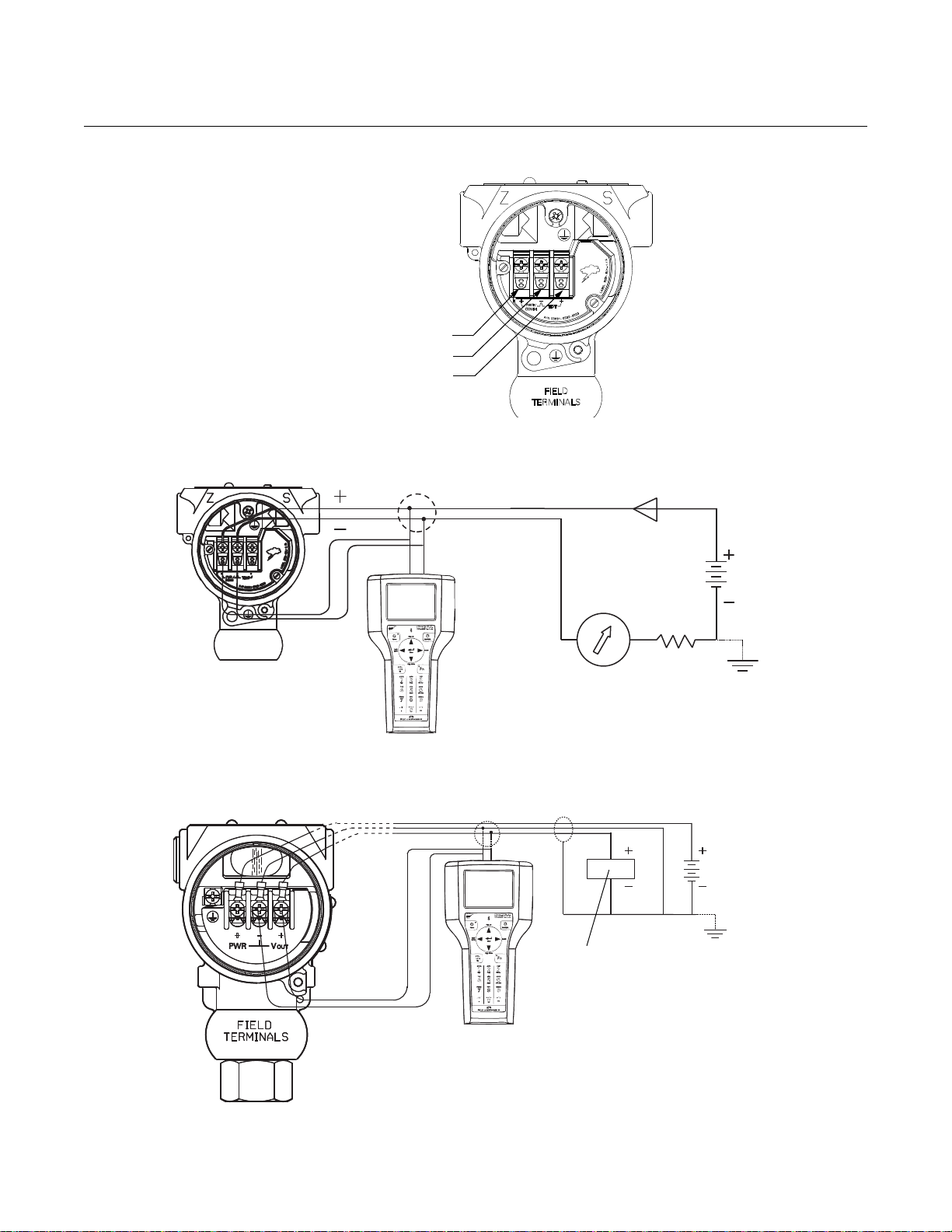
To connect test equipment for monitoring the output of the Rosemount
2088/2090 transmitter during maintenance procedures, connect one lead to
the terminal labeled “TEST+” and the other lead to the terminal labeled “–”
(see Figure 2-11). Avoid contact with the leads and the terminals.
Signal wiring may be grounded at any one point on the measurement loop, or
it may be left ungrounded. The negative side of the power supply is a
recommended grounding point. The transmitter case may be grounded or left
ungrounded.
Conduit connections at the transmitter should be sealed to prevent moisture
accumulating in the field terminal side of the transmitter housing. Also, install
wiring with a drip loop with the bottom of the drip loop lower than the conduit
connection of the transmitter housing.
2-19
Page 30
Rosemount 2088 and 2090
Positive
Negative
Test
Power
Supply
RL250
Power
Supply
Voltmeter
Figure 2-11. Rosemount 2088/2090 Transmitter Signal Wiring Terminals
Figure 2-12. 4-20 mA HART Transmitter Wiring Diagram
Reference Manual
00809-0100-4690, Rev FC
June 2011
Figure 2-13. 1-5 mA Vdc HART Low Power Transmitter Wiring
2-20
Page 31

Reference Manual
00809-0100-4690, Rev FC
June 2011
Rosemount 2088 and 2090
T ransient Protection
Terminal Block
The transmitter will withstand electrical transients of the energy level usually
encountered in static discharges or induced switching transients. However,
high-energy transients, such as those induced in wiring from nearby lightning
strikes, can damage the transmitter.
The transient protection terminal block can be ordered as an installed option
(Option Code T1 in the transmitter model number) or as a spare part to retrofit
existing 2088 transmitters in the field. See “Spare Parts” on page A-7 for
spare part numbers.
NOTE
The transient protection terminal block does not provide transient protection
unless the transmitter case is properly grounded. Use the guidelines to
ground the transmitter case.
Do not run the transient protection ground wire with signal wiring as the
ground wire may carry excessive current if a lightning strike occurs.
Grounding Use the following techniques to properly ground the transmitter signal wiring
and case:
Signal Wiring
Do not run signal wiring in conduit or open trays with power wiring or near
heavy electrical equipment. It is important that the instrument cable shield be:
• Trimmed close and insulated from touching the transmitter housing
• Connected to the next shield if cable is routed through a junction box
• Connected to a good earth ground at the power supply end
HAZARDOUS LOCATIONS CERTIFICATIONS
For 4-20 mA HART output, the signal wiring may be grounded at any one
point on the signal loop or may be left ungrounded. The negative terminal of
the power supply is a recommended grounding point.
For 1-5 Vdc HART Low Power output, the power wires may be grounded at
only one point or left ungrounded. The negative terminal of the power supply
is a recommended grounding point.
Transmitter Case
Always ground the transmitter case in accordance with national and local
electrical codes. The most effective transmitter case grounding method is a
direct connection to earth ground with minimal impedance. Methods for
grounding the transmitter case include:
• Internal Ground Connection: The Internal Ground Connection screw
is inside the FIELD TERMINALS side of the electronics housing. This
screw is identified by a ground symbol ( ). The ground connection
screw is standard on all Rosemount 2088 transmitters.
Individual transmitters are clearly marked with a tag indicating the approvals
they carry. Transmitters must be installed in accordance with all applicable
codes and standards to maintain these certified ratings. Refer to “Hazardous
Locations Certifications” on page B-1 for information on these approvals.
2-21
Page 32

Rosemount 2088 and 2090
Reference Manual
00809-0100-4690, Rev FC
June 2011
2-22
Page 33

Reference Manual
00809-0100-4690, Rev FC
June 2011
Rosemount 2088 and 2090
Section 3 Configuration
Overview . . . . . . . . . . . . . . . . . . . . . . . . . . . . . . . . . . . . . . . page 3-1
Safety Messages . . . . . . . . . . . . . . . . . . . . . . . . . . . . . . . . . page 3-1
Commissioning . . . . . . . . . . . . . . . . . . . . . . . . . . . . . . . . . . page 3-2
Configuration Data Review . . . . . . . . . . . . . . . . . . . . . . . . page 3-4
Field Communicator Menu Tree . . . . . . . . . . . . . . . . . . . .page 3-5
Fast Key Sequence . . . . . . . . . . . . . . . . . . . . . . . . . . . . . . . page 3-7
Check Output . . . . . . . . . . . . . . . . . . . . . . . . . . . . . . . . . . . page 3-8
Basic Setup . . . . . . . . . . . . . . . . . . . . . . . . . . . . . . . . . . . . .page 3-8
LCD Display . . . . . . . . . . . . . . . . . . . . . . . . . . . . . . . . . . . . .page 3-11
Detailed Setup . . . . . . . . . . . . . . . . . . . . . . . . . . . . . . . . . . .page 3-14
Diagnostics and Service . . . . . . . . . . . . . . . . . . . . . . . . . . page 3-16
Multidrop Communication . . . . . . . . . . . . . . . . . . . . . . . . .page 3-17
OVERVIEW This section contains information on commissioning and tasks that should be
performed on the bench prior to installation.
Field Communicator and AMS Device Manager instructions are given to
perform configuration functions. For convenience, Field Communicator fast
key sequences are labeled “Fast Keys” for each software function below the
appropriate headings.
SAFETY MESSAGES Procedures and instructions in this section may require special precautions to
ensure the safety of the personnel performing the operations. Information that
raises potential safety issues is indicated by a warning symbol. Refer to the
following safety messages before performing an operation preceded by this
symbol.
Explosions could result in death or serious injury:
Installation of this transmitter in an explosive environment must be in accordance with
the appropriate local, national, and international standards, codes, and practices.
Please review the approvals section of the 2051 reference manual for any restrictions
associated with a safe installation.
• Before connecting a Field Communicator in an explosive atmosphere, ensure
the instruments in the loop are installed in accordance with intrinsically safe or
non-incendive field wiring practices.
• In an Explosion-Proof/Flameproof installation, do not remove the transmitter
covers when power is applied to the unit.
Process leaks may cause harm or result in death.
• Install and tighten process connectors before applying pressure.
Electrical shock can result in death or serious injury.
• Avoid contact with the leads and terminals. High voltage that may be present
on leads can cause electrical shock.
www.rosemount.com
Page 34

Reference Manual
00809-0100-4690, Rev FC
Rosemount 2088 and 2090
June 2011
COMMISSIONING Commissioning consists of testing the transmitter and verifying transmitter
configuration data. The Rosemount 2088/2090 can be commissioned either
before or after installation. Commissioning the transmitter on the bench before
installation using a Field Communicator or AMS Device Manager ensures that
all transmitter components are in working order.
To commission on the bench, required equipment includes a power supply, a
milliamp meter, and a Field Communicator or AMS Device Manager. Wire
equipment as shown in Figure 3-1 and Figure 3-2. To ensure successful
communication, a resistance of at least 250 ohms must be present between
the Field Communicator loop connection and the power supply. Connect the
Field Communicator leads to the terminals labeled “COMM” on the terminal
block. Set all transmitter hardware adjustments during commissioning to
avoid exposing the transmitter electronics to the plant environment after
installation.
When using a Field Communicator, any configuration changes made must be
sent to the transmitter by using the “Send” key. AMS Device Manager
configuration changes are implemented when the “Apply” button is clicked.
Setting the Loop to
Manual
Whenever sending or requesting data that would disrupt the loop or change
the output of the transmitter, set the process application loop to manual. The
Field Communicator or AMS Device Manager will prompt you to set the loop
to manual when necessary. Acknowledging this prompt does not set the loop
to manual. The prompt is only a reminder; set the loop to manual as a
separate operation.
Wiring Diagrams Connect the equipment as shown in Figure 3-1 for 4-20 mA HART or
Figure 3-2 for 1-5 Vdc HART Low Power. To ensure successful
communication, a resistance of at least 250 ohms must be present between
the Field Communicator loop connection and the power supply. The Field
Communicator or AMS Device Manager may be connected at “COMM” on the
transmitter terminal block or across the resistor. Connecting across the
“TEST” terminals will prevent successful communication for the 4-20 mA
HART output.
Turn on the Field Communicator by pressing the ON/OFF key or log into AMS
Device Manager. The Field Communicator or AMS Device Manager will
search for a HART-compatible device and indicate when the connection is
made. If the Field Communicator or AMS Device Manager fail to connect, it
indicates that no device was found. If this occurs, refer to Section 5:
Troubleshooting.
3-2
Page 35

Reference Manual
Power
Supply
RL250
Power
Supply
Voltmeter
00809-0100-4690, Rev FC
June 2011
Figure 3-1. 4-20 mA HART
Transmitter Wiring Diagram
Figure 3-2. 1-5 Vdc HART Low
Power Transmitter Wiring
Rosemount 2088 and 2090
3-3
Page 36

Rosemount 2088 and 2090
Reference Manual
00809-0100-4690, Rev FC
June 2011
CONFIGURATION DATA REVIEW
NOTE
Information and procedures in this section that make use of Field
Communicator fast key sequences and AMS Device Manager assume that
the transmitter and communication equipment are connected, powered, and
operating correctly.
The following is a list of factory default configurations. These can be reviewed
by using the Field Communicator or AMS Device Manager
Field Communicator
4-20 mA Fast Keys
1, 5
Enter the fast key sequence to view the configuration data.
Ta g Range
Date Descriptor
Message Minimum and Maximum Sensor Limits
Minimum Span Units
4 and 20 mA points Output (linear or sq. root)
Damping Alarm Setting (high, low)
Security Setting (on, off) Local Zero/Span Keys (enabled,
Integral Display Sensor Fill
Isolator Material Flange (type, material)
O-Ring Material Drain/Vent
Remote Seal (type, fill fluid, isolator material,
number)
Address Sensor S/N
disabled)
Transmitter S/N
AMS Device Manager
Right click on the device and select “Configuration Properties” from the menu.
Select the tabs to review the transmitter configuration data.
3-4
Page 37

Reference Manual
Pressure
Percent Range
Analog Output
1 Tag
2 Unit
3 RANGE VALUES
4 DEVICE INFO
5 Damp
6 DISPLAY
OPTIONS
1 Self test
2 Status
1 Keypad Input
2 Apply Values
1 Loop Test
2 Digital-to-Analog Trim
3 Scaled D/A Trim
4 AO Alarm Type
1 Poll Address
2 Number of Req.
Pream.
3 Burst Mode
4 Burst Option
1 Digital-to-Analog Trim
2 Scaled D/A Trim
1 Zero Trim
2 Lower Sensor Trim
3 Upper Sensor Trim
4 Sensor T rim Cal Type
5 Sensor Trim Points
1 Date
2 Descriptor
3 Message
4 Write Protect
1 Keypad Input
2 Apply Values
1 Pressure
2 Percent Range
1 Keypad Input
2 Apply Values
1 Pressure
2 Percent Range
3 Analog Output
1 FIELD DEVICE INFO
2 SENSOR INFO
3 Self Test
4 DIAPHRAGM
SEALS INFO
1 DEVICE SETUP
2 PV
3 AO
4 LRV
5 URV
PROCESS
VARIABLES
DIAGNOSTICS
AND SERVICE
BASIC SETUP
DETAILED
SETUP
REVIEW
1 TEST DEVICE
2 Loop Test
3 CALIBRATION
1 RERANGE
2 ANALOG
OUTPUT TRIM
3 SENSOR TRIM
1 Pressure
2 % Range
1 PROCESS
VARIABLES
2 SENSOR
TRIM
3 Unit
Online Menu
1 PRESSURE
SNSR
1 SENSORS
2 SIGNAL
CONDITION
3 OUTPUT
CONDITION
4 DEVICE
INFORMATION
1 Tag
2 Date
3 Descriptor
4 Message
5 Model
6 Write Protect
7 Local Keys
8 REVISION #s
9 Final Assy #
Device ID
Distributor
1 Measurement Type
2 Isolator Material
3 Fill Type
4 Proc. Conn. Type
5 Proc. Conn.
Material
1 Display Type
2 CUSTOM
DISPLAY
SETUP
1 PROCESS
VARIABLES
2 RANGE VALUES
3 Unit
4 Damp
1 PROCESS
VARIABLES
2 ANALOG
OUTPUT
3 HART OUTPUT
4 METER
OPTIONS
1 Diaph. Seal Type
2 Diaph. Seal Fill
Fluid
3 Diaph. Seal
Material
1 Display Type
2 CUSTOM
DISPLAY SETUP
3 Custom Display
Value
1 Select Dec. Pt. Pos.
2 CM Upper Value
3 CM Lower V alue
4 CM Units
1 Univ. Rev.
2 Fld. Dev.
Rev.
3 S/W Rev.
00809-0100-4690, Rev FC
June 2011
Rosemount 2088 and 2090
FIELD COMMUNICATOR MENU TREE
Figure 3-3. Rosemount 2088/2090 HART menu tree for 4-20 mA HART
3-5
Page 38

Rosemount 2088 and 2090
1 DEVICE
SETUP
2PV
3AO
4LRV
5URV
1 PROCESS
VAR IAB LE
2 DIAGNOSTICS
AND SERVICE
3 BASIC SETUP
4 DETAILED
SETUP
5Review
1 Pressure
2 Percent Range
3 Analog Output
4 Sensor
Temperature
1 TEST DEVICE
2 Loop Test
3CALIBRATION
1Self Test
2Status
1RERANGE
2TRIM ANALOG
OUTPUT
3SENSOR TRIM
1SENSORS
2SIGNAL
CONDITION
3OUTPUT
CONDITION
4DEVICE
INFORMATION
1 Keypad Input
2 Apply Values
1 Digital-to-Analog Trim
2 Scaled D/A Trim
1 Zero Trim
2 Lower Sensor Trim
3 Upper Sensor Trim
4 Sensor Trim Points
1 Keypad Input
2 Apply Values
1Date
2Descriptor
3 Message
4 Write Protect
5 Meter Type
1Tag
2Unit
3 RANGE VALUES
4 DEVICE INFO
5 Transfer Function
6Damp
1 PRESSURE
SENSOR
2 TEMP SENSOR
1 Sensor Temp
2 Sensor Temp Unit
1 PROCESS VARIABLE
2 SENSOR SERVICE
3Unit
1Pressure
2% Range
3Sensor Temp
1 SENSOR
TRIM
1Zero Trim
2 Lower
Sensor Trim
3 Upper
Sensor Trim
4 Sensor Trim
Points
1 PROCESS
VARIABLE
2RANGE
VAL UES
3Unit
4Transfer Func
5Damp
1 PROCESS
VARIABLES
2ANALOG
OUTPUT
3 AO Alarm Type
4 HART OUTPUT
1FIELD DEVICE
INFO
2SENSOR INFO
3 Meter Type
4Self Test
1 Pressure
2 % Range
3 Snsr Temp
1Keypad Input
2 Apply Values
1 Pressure
2 % Range
3 Analog Output
4 Sensor Temp
1 Loop Test
2 Digital-to-Analog Trim
3 Scaled D/A Trim
4 AO Alarm Type
1 Poll Address
2 Nos. of Req. Pream.
3 Burst Mode
4 Burst Option
1 Measurement Type
2 Mod. Config. Type
3 Isolator Material
4 Fill Fluid
5 Flange Type
6 Proc. Conn. Material
7 Flange Material
8 Drain/Vent Material
9 # of Diaphr. Seals
Diaphr. Seal Type
Diaphr. Material
1Tag
2Date
3 Descriptor
4 Message
5 Model
6 Write Protect
7 Local Keys
8REVISION #S
9Final Assy #
Device ID
Distributor
1Univ. Rev.
2 Fid. Dev. Rev.
3S/W Rev.
Figure 3-4. Rosemount 2088 HART Menu Tree for 1-5 Vdc Low Power
Reference Manual
00809-0100-4690, Rev FC
June 2011
3-6
Page 39

Reference Manual
00809-0100-4690, Rev FC
June 2011
Rosemount 2088 and 2090
FAST KEY SEQUENCE
Table 3-1. HART Fast Key Sequences for the Rosemount 2088/2090.
A check () indicates the basic configuration parameters. At minimum, these parameters should be verified as part of the
configuration and startup procedure
Function HART Fast Key Sequence
Analog Output Alarm 1, 4, 3, 2, 4
Burst Mode Control 1, 4, 3, 3, 3
Burst Option 1, 4, 3, 3, 4
Calibration 1, 2, 3
Damping 1, 3, 5
Date 1, 3, 4, 1
Descriptor 1, 3, 4, 2
Digital To Analog Trim (4–20 mA Output) 1, 2, 3, 2, 1
Disable Local Span/Zero Adjustment 1, 4, 4, 1, 7
Field Device Info 1, 4, 4, 1
Keypad Input 1, 2, 3, 1, 1
Loop Test 1, 2, 2
Lower Range Value 4, 1
Lower Sensor Trim 1, 2, 3, 3, 2
Message 1, 3, 4, 3
Meter Type 1, 3, 6, 1
Number of Requested Preambles 1, 4, 3, 3, 2
Output Trim 1, 2, 3, 2
Percent Range 1, 1, 2
Poll Address 1, 4, 3, 3, 1
Range Values 1, 3, 3
Rerange 1, 2, 3, 1
Scaled D/A Trim (4–20 mA Output) 1, 2, 3, 2, 2
Self Test (Transmitter) 1, 2, 1, 1
Sensor Info 1, 4, 4, 2
Sensor Trim (Full Trim) 1, 2, 3, 3
Sensor Trim Points 1, 2, 3, 3, 5
Status 1, 2, 1, 2
Ta g 1, 3, 1
Transmitter Security (Write Protect) 1, 3, 4, 4
Units (Process Variable) 1, 3, 2
Upper Range Value 5, 2
Upper Sensor Trim 1, 2, 3, 3, 3
Zero Trim 1, 2, 3, 3, 1
3-7
Page 40

Reference Manual
00809-0100-4690, Rev FC
Rosemount 2088 and 2090
June 2011
CHECK OUTPUT Before performing other transmitter on-line operations, review the digital
output parameters to ensure that the transmitter is operating properly and is
configured to the appropriate process variables.
Process Variables
The process variables for the Rosemount 2088/2090 provide the transmitter
output, and are continuously updated. The Process Variables menu displays
the following process variables:
• Pressure
• Percent Range
• Analog Output
Field Communicator
4-20 mA Fast Keys
1, 1
BASIC SETUP From the Basic Setup menu you can configure the transmitter for certain
basic variables. In many cases, all of these variables are pre-configured at the
factory. Configuration may be required if your transmitter is not configured or if
the configuration variables need revision.
Tag The Tag variable is the easiest way to identify and distinguish between
transmitters in multi-transmitter environments. Use this variable to label
transmitters electronically according to the requirements of your application.
The tag you define is automatically displayed when a Field Communicator
establishes contact with the transmitter at power-up. The tag may be up to
eight characters long and has no impact on the primary variable readings of
the transmitter.
Field Communicator
4-20 mA Fast Keys
1, 3, 1
Set Units The Unit command sets the desired primary variable units. Set the transmitter
output to one of the following engineering units:
inH20 g/cm
inHg kg/cm
ftH20 Pa
mmH20 kPa
psi torr
bar atm
mbar mmH20 @ 4 °C
nH2O @ 4 °C
Field Communicator
4-20 mA Fast Keys
2
2
1, 3, 2
3-8
NOTE
After changing units, press SEND so the microprocessor will recalculate the
associated variables (4–20 mA points, for example). The Rosemount
2088/2090 recalculates all variables that depend on units. After the
transmitter recalculates the variables, you may change any of the remaining
parameters.
Page 41

Reference Manual
00809-0100-4690, Rev FC
June 2011
Rosemount 2088 and 2090
Rerange The Range Values command sets each of the lower and upper range analog
values (4 and 20 mA points and 1 and 5 Vdc points) to a pressure. The lower
range point represents 0% of range and the upper range limit represents
100% of range. Setting the range values to the limits of expected readings
maximizes transmitter performance; the transmitter is most accurate when
operated within the expected pressure ranges for your application. In practice,
you may reset the transmitter range values as often as necessary to reflect
changing process conditions.
NOTE
Transmitters are shipped from Emerson Process Management fully calibrated
per request or by the factory default of full scale (zero to upper range limit).
NOTE
Regardless of the range points, the Rosemount 2088/2090 will measure and
report all readings within the digital limits of the sensor. For example, if the 4
and 20 mA points are set to 0 and 10 inH
pressure of 25 inH
percent of span reading.
0, it digitally outputs the 25 inH20 reading and a 250
2
0, and the transmitter detects a
2
You may use one of three methods to rerange the transmitter. Each method is
unique; examine all three closely before deciding which method to use.
Method 1: Rerange with a Field Communicator or AMS Device Manager
This is the easiest and most popular way to rerange the transmitter. This
method changes the values of the analog 4 and 20 mA points (1 and 5 Vdc
points) independently without a pressure input. This means that when you
change either the 4 or 20 mA setting, you also change the span.
To rerange using only the communicator enter the fast-key sequence above,
select 1 Keypad input, and follow the on-line instructions or enter the values
directly from the HOME screen.
Field Communicator
4-20 mA Fast Keys
Method 2: Rerange Using the Communicator and a Pressure Source or
Process Pressure
Reranging using the communicator and a pressure source or process
pressure is a way of reranging the transmitter when specific 4 and 20 mA
points (1 and 5 Vdc points) are not known.
NOTE
The span is maintained when the 4 mA point (1 Vdc point) is set. The span
changes when the 20 mA point (5 Vdc point) is set. If the lower range point is
set to a value that causes the upper range point to exceed the sensor limit,
the upper range point is automatically set to the sensor limit, and the span is
adjusted accordingly.
1, 3, 3
To rerange using the communicator and a pressure source or process
pressure, enter the fast-key sequence above, select 2 Apply values, and
follow the on-line instructions.
3-9
Page 42

Rosemount 2088 and 2090
Span and Zero Adjustment Buttons
Method 3: Rerange Using the Local Zero and Span Buttons
and a Pressure Source or Process Pressure
The Rosemount 2088/2090 is equipped with local zero and span adjustment
buttons. The buttons are located on the top of the transmitter beneath the
certifications label. Use the zero and span adjustments to set the 4 and 20 mA
output points.
To rerange the transmitter using the span and zero buttons, perform the
following procedure.
1. Loosen the screw holding the nameplate on top of the transmitter
housing and rotate the nameplate to expose the zero and span
buttons (see Figure 3-5).
2. Using a pressure source with an accuracy three to ten times the
desired calibrated accuracy, apply a pressure equivalent to the lower
range value.
3. To set the 4 mA point, press and hold the zero button for at least two
seconds, then verify that the output is 4 mA. If a display is installed, it
will display ZERO PASS.
4. Apply a pressure equivalent to the upper range value.
5. To set the 20 mA point, press and hold the span button for at least two
seconds, then verify that the output is 20 mA. If a display is installed, it
will display SPAN PASS.
Reference Manual
00809-0100-4690, Rev FC
June 2011
Figure 3-5. Local Zero
and Span Adjustments
NOTE
If the transmitter security jumper is in the “ON” position, or if the local zero and
span adjustments are disabled through the software, you will not be able to
make adjustments to the zero and span using the local buttons. Refer to
Figure 2-9 on page 2-17 for the proper placement of the transmitter security
jumper.
Disabling the Zero
and Span Adjustments
After you rerange the transmitter using the span and zero adjustments, you
may wish to disable the adjustments to prevent further reranging. To disable
the span and zero adjustments, activate the transmitter security jumper.
3-10
Page 43

Reference Manual
00809-0100-4690, Rev FC
June 2011
Rosemount 2088 and 2090
Damping The Damping command changes the response time of the transmitter to
smooth variations in output readings caused by rapid changes in input.
Determine the appropriate damping setting based on the necessary response
time, signal stability, and other requirements of the loop dynamics of your
system. The default damping value is 0.50 seconds and can be reset in fixed
increments of 0.05, 0.10, 0.20, 0.40, 0.80, 1.60, 3.20, 6.40, 12.8, or 25.6
seconds.
Field Communicator
4-20 mA Fast Keys
1, 3, 5
LCD DISPLAY The LCD display connects directly to the interface board which maintains
direct access to the signal terminals. The display indicates output and
abbreviated diagnostic messages. A display cover is provided to
accommodate the display.
For 4-20 mA HART output, the LCD display features a two-line display. The
first line of five characters displays the actual measured value. The second
line of six characters displays the engineering units. The LCD can also display
diagnostic messages. Refer to Figure 3-6.
Figure 3-6. LCD Display
4-20 mA HART 1-5 Vdc HART Low Power
For 1-5 Vdc HART Low Power output, the LCD display features a single-line
display with four characters that display the actual value. The LCD can also
display diagnostic messages. Refer to Figure 3-6.
3-11
Page 44

Rosemount 2088 and 2090
See “Safety Messages” on page 3-1 for complete warning information.
Reference Manual
00809-0100-4690, Rev FC
June 2011
LCD Display
Configuration for 4-20
mA HART only
The factory default is Percent of Range (M5 option) or Engineering Units (M7
option). The LCD Display Configuration command allows customization of the
LCD display to suit application requirements. The LCD display will alternate
between the selected items:
• Eng. Units only • Alternate Eng. Units & % of Range
• % of Range only • Alternate Eng. Units & Custom Display
• Custom Display only • Alternate % of Range & Custom Display
Field Communicator
4-20 mA Fast Keys
To change the standard default to one of the above options, follow these
steps:
1. From the communicators main menu select (1) Device Setup (3)
Basic Setup, (7) Meter Options.
2. Select (1) Meter Type. Using the up or down arrows scroll up or down
until the desired display has been highlighted. Press ENTER, SEND,
and HOME.
AMS
Right click on the device and select “Configuration Properties” from the menu.
1. In the “Local Display” tab, locate the “Meter Type” area. Select the
desired options to suit your application needs, click Apply.
2. An “Apply Parameter Modification” screen appears. Enter desired
information and click OK.
3. After carefully reading the warning provided, select OK.
1, 3, 7
Custom Display
Configuration 4-20 mA
HART only
The user-configurable scale is a feature that enables the LCD display to
display flow, level, or custom pressure units. With this feature you can define
the decimal point position, the upper range value, the lower range value, the
engineering units, and the transfer function.The display can be configured
using a Field Communicator or AMS.
The user-configurable scale feature can define:
• decimal point position
• upper range values
• lower range values
• engineering units
• transfer function
To configure the display with a Field Communicator, perform the following
procedure:
1. Change the Meter Type to “Custom Meter” by using the Fast Key
sequence under “LCD Display Configuration for 4-20 mA HART only”
on page 3-12.
2. Next, from the ONLINE screen, Select 1 Device Setup, 3 Basic
Setup, 7 Meter Options, 2 Meter Options, 2 Custom Meter Setup.
3-12
Page 45

Reference Manual
00809-0100-4690, Rev FC
June 2011
Rosemount 2088 and 2090
To specify decimal point position:
a. Select 1 Sel dec pt pos. Choose the decimal point representation
that will provide the most accurate output for your application. For
example, when outputting between 0 and 75 GPM, choose
XX.XXX or use the decimal point examples below:
XXXXX
XXXX.X
XXX.XX
XX.XXX
X.XXXX
NOTE:
Make sure the selection has been sent and the decimal point has changed
before proceeding to the next step.
b. SEND
3. To specify a custom upper range value:
a. Select 2 CM Upper Value. Type the value that you want the
transmitter to read at the 20 mA point.
b. SEND
4. To specify a custom lower range value:
a. Select 3 CM Lower Value. Type the value that you want the
transmitter to read at the 4 mA point.
b. SEND
5. To define custom units:
a. Select 4 CM Units. Enter the custom units (five characters
maximum) that you want the display to display.
b. SEND
6. To choose the transmitter transfer function for the display:
a. Select 5 CM xfer fnct. Enter the transmitter transfer function for the
display. Select sq root to display flow units. The custom meter
transfer function is independent of the analog output transfer
function.
7. Select SEND to upload the configuration to the transmitter.
3-13
Page 46

Rosemount 2088 and 2090
DETAILED SETUP
Reference Manual
00809-0100-4690, Rev FC
June 2011
Failure Mode Alarm and
Saturation
Table 3-2. 4-20 mA HART
Alarm and Saturation Values
Table 3-3. NAMUR-Compliant
Alarm and Saturation Values
As part of normal operation, the Rosemount 2088/2090 Pressure Transmitter
continuously monitors its own operation. This automatic diagnostic routine is
a timed series of checks repeated continuously. If the diagnostic routine
detects a failure in the transmitter, the transmitter drives its output either
below or above specific values depending on the position of the failure mode
jumper or switch.
The values to which transmitters drive their output in failure mode depend on
whether they are factory-configured to standard or NAMUR-compliant
operation. The values for each are as follows:
Level 4–20 mA Saturation 4–20 mA Alarm
Low 3.9 mA 3.75 mA
High 20.8 mA 21.75 mA
Level 4–20 mA Saturation 4–20 mA Alarm
Low 3.8 mA 3.6 mA
High 20.5 mA 22.5 mA
Table 3-4. 1-5 Vdc HART
Low-Power Alarm and
Saturation Values
Level 1–5 V Saturation 1–5 V Alarm
Low 0.97 V 0.95 V
High 5.20 V 5.4 V
To determine the failure mode configuration of your transmitter, review the
failure mode options using a Field Communicator.
NOTE
The failure mode configuration, whether standard or NAMUR-compliant, is
configured at the factory and can not be changed in the field.
3-14
Page 47

Reference Manual
00809-0100-4690, Rev FC
June 2011
Rosemount 2088 and 2090
Burst Mode Burst Mode sets the transmitter to maintain digital contact with a Digital
Control System that has custom software to support burst mode. When the
Rosemount 2088 transmitter is configured for burst mode, it provides faster
digital communication from the transmitter to the control system by eliminating
the time required for the control system to request information from the
transmitter.
Burst mode is compatible with use of the analog signal. Because HART
protocol features simultaneous digital and analog data transmission, the
analog value can drive other equipment in the loop while the control system is
receiving the digital information. Burst mode applies only to the transmission
of dynamic data (pressure and temperature in engineering units, pressure in
percent of range, and/or analog output in mA), and does not affect the way
other transmitter data is accessed.
Field Communicator
4-20 mA Fast Keys
Access to information other than dynamic transmitter data is obtained through
the normal poll/response method of HART communication. A Field
Communicator or the control system may request any of the information that
is normally available while the transmitter is in burst mode. Between each
message sent by the transmitter, a short pause allows the Field
Communicator or a control system to initiate a request. The transmitter will
receive the request, process the response message, and then continue
“bursting” the data approximately three times per second.
1, 4, 3, 3, 3
®
Alarm and Saturation
Levels for Burst Mode
Alarm and Saturation
Values for Multidrop
Mode
Transmitters set to burst mode handle saturation and alarm conditions
differently.
Alarm Conditions:
• Analog output switches to alarm value
• Primary variable is burst with a status bit set
• Percent of range follows primary variable
• Temperature is burst with a status bit set
Saturation:
• Analog output switches to saturation value
• Primary variable is burst normally
• Temperature is burst normally
Transmitters set to multidrop mode handle saturation and alarm conditions
differently.
Alarm Conditions:
• Primary variable is sent with a status bit set
• Percent of range follows primary variable
• Temperature is sent with a status bit set
Saturation:
• Primary variable is sent normally
• Temperature is sent normally
3-15
Page 48

Reference Manual
00809-0100-4690, Rev FC
Rosemount 2088 and 2090
June 2011
Alarm Level Verification If the transmitter electronics board, sensor module, or LCD display is repaired
or replaced, verify the transmitter alarm level before returning the transmitter
to service. This feature is also useful in testing the reaction of the control
system to a transmitter in an alarm state. To verify the transmitter alarm
values, perform a loop test and set the transmitter output to the alarm value.
Save, Recall, or Clone
Configuration Data
Data that was entered off-line can be stored in the communicator memory and
downloaded to other transmitters later. Data also can be copied from a
transmitter in order to be sent to other transmitters in a process known as
“cloning.” This is especially useful if you work with a large number of
transmitters that require the same configuration data.
Field Communicator
4-20 mA Fast Keys
left arrow, 3 (note)
DIAGNOSTICS AND SERVICE
Test Device The Test Device command initiates a more extensive diagnostic routine than
that performed continuously by the transmitter. The transmitter test routine
can identify an electronics failure. If the transmitter test detects a problem, the
communicator displays messages to indicate the source of the problem.
Field Communicator
4-20 mA Fast Keys
1, 2, 1, 1
Loop Test The Loop Test command verifies the output of the transmitter, the integrity of
the loop, and the operations of any recorders or similar devices installed in the
loop. To initiate a loop test, perform the following procedure:
Field Communicator
4-20 mA Fast Keys
1, 2, 2
3-16
1. Connect a reference meter to the transmitter. To do so, either connect
the meter to the test terminals on the transmitter terminal block, or
shunt the power to the transmitter through the meter at some point in
the loop.
2. From the HOME screen, Select 1 Device Setup, 2 Diagnostics and
Service, 2 Loop Test, to prepare to perform a loop test.
3. Select “OK” after you set the control loop to manual.
The communicator displays the loop test menu.
4. Select a discreet milliamp level for the transmitter to output. At the
“Choose analog output” prompt, select 1 4mA, 2 20mA, or select 3
other to manually input a value between 4 and 20 mA.
5. Check the current meter installed in the test loop to verify that it reads
the value you commanded the transmitter to output. If the readings do
not match, the transmitter requires an output trim or the current meter
is malfunctioning.
After completing the test procedure, the display returns to the loop test screen
and allows you to choose another output value.
Page 49

Reference Manual
HART
Modem
Power
Supply
00809-0100-4690, Rev FC
June 2011
Rosemount 2088 and 2090
MULTIDROP COMMUNICATION
Figure 3-7. Typical
Multidrop Network.
Multidropping transmitters refers to the connection of several transmitters to a
single communications transmission line. Communication between the host
and the transmitters takes place digitally with the analog output of the
transmitters deactivated. Many of the Rosemount transmitters can be
multidropped. With the HART communications protocol, up to 15 transmitters
can be connected on a single twisted pair of wires or over leased phone lines.
Note that Burst Mode Operation is not compatible with multidrop
communications.
The application of a multidrop installation requires consideration of the update
rate necessary from each transmitter, the combination of transmitter models,
and the length of the transmission line. Multidrop installations are not
recommended where intrinsic safety is a requirement. Communication with
the transmitters can be accomplished with commercially available HART
modems and a host implementing the HART protocol. Each transmitter is
identified by a unique address (1-15) and responds to the commands defined
in the HART protocol.
Figure 3-7 shows a typical multidrop network. This figure is not intended as an
installation diagram. Contact Rosemount product support with specific
requirements for multidrop applications.
HART-based communicators can test, configure, and format a multidropped
transmitter the same way as a transmitter in a standard point-to-point
installation.
NOTE
The transmitter is set to address 0 at the factory, allowing it to operate in the
standard point-to-point manner with a 4–20 mA output signal. To activate
multidrop communication, you must change the transmitter address to a
number from 1 to 15. This change deactivates the 4–20 mA analog output,
locking it to 4 mA. It also disables the failure mode alarm signal, which is
controlled by the upscale/downscale jumper position.
3-17
Page 50

Rosemount 2088 and 2090
Reference Manual
00809-0100-4690, Rev FC
June 2011
Changing a Transmitter
Address
Communicating with a
Multidropped
Transmitter
Polling a Multidropped
Loop
To change the address of a multidropped transmitter, follow these fast key
sequences. To activate multidrop communication, the transmitter address
must be changed to a number from 1 to 15.
Field Communicator
4-20 mA Fast Keys
To communicate with a multidropped transmitter for the purpose of testing,
configuring, or formatting.
Field Communicator
4-20 mA Fast Keys
Polling a multidropped loop determines the model, address, and number of
transmitters on the given loop.
Field Communicator
4-20 mA Fast Keys
1, 4, 3, 3, 1
1, 4, 3, 3, 2
Left Arrow, 4, 1, 1
3-18
Page 51

Reference Manual
00809-0100-4690, Rev FC
June 2011
Rosemount 2088 and 2090
Section 4 Operation and Maintenance
Overview . . . . . . . . . . . . . . . . . . . . . . . . . . . . . . . . . . . . . . . page 4-1
Safety Messages . . . . . . . . . . . . . . . . . . . . . . . . . . . . . . . . . page 4-1
Calibration Overview . . . . . . . . . . . . . . . . . . . . . . . . . . . . . page 4-2
Analog Output Trim . . . . . . . . . . . . . . . . . . . . . . . . . . . . . . page 4-5
Sensor Trim . . . . . . . . . . . . . . . . . . . . . . . . . . . . . . . . . . . . . page 4-8
OVERVIEW This section contains information on calibrating and diagnostics messages on
the Rosemount 2088/2090 Pressure Transmitters.
Field Communicator and AMS instructions are given to perform configuration
functions. For convenience, Field Communicator fast key sequences are
labeled “Fast Keys” for each software function below the appropriate
headings.
SAFETY MESSAGES Procedures and instructions in this section may require special precautions to
ensure the safety of the personnel performing the operations. Information that
raises potential safety issues is indicated by a warning symbol ( ). Refer to the
following safety messages before performing an operation preceded by this
symbol.
Explosions could result in death or serious injury:
Installation of this transmitter in an explosive environment must be in accordance with the
appropriate local, national, and international standards, codes, and practices. Please review
the approvals section of the reference manual for any restrictions associated with a safe
installation.
• Before connecting a Field Communicator in an explosive atmosphere, ensure the
instruments in the loop are installed in accordance with intrinsically safe or
non-incendive field wiring practices.
• In an Explosion-Proof/Flameproof installation, do not remove the transmitter covers
when power is applied to the unit.
Process leaks may cause harm or result in death.
• Install and tighten process connectors before applying pressure.
Electrical shock can result in death or serious injury.
Avoid contact with the leads and terminals. High voltage that may be present on leads can
•
cause electrical shock.
www.rosemount.com
Page 52

Rosemount 2088 and 2090
Reference Manual
00809-0100-4690, Rev FC
June 2011
CALIBRATION OVERVIEW
Calibration is defined as the process required to optimize transmitter accuracy
over a specific range by adjusting the factory sensor characterization curve
located in the microprocessor. Possible procedures are:
• Reranging: Setting the lower and upper range points (4 and 20 mA or 1
and 5 Vdc) points at required pressures. Reranging does not change the
factory sensor characterization curve. Refer to page 3-9.
• Analog Output Trim: Adjusts the transmitter’s analog characterization
curve to match the plant standard of the control loop. There are two types
of digital-to-analog output trims. Refer to page 4-5.
• Digital-to-Analog Output Trim on 4-20 mA HART output (page 4-5)
• Digital-to-Analog Output Trim on 4-20 mA HART output Using Other
Scale (page 4-6)
• Sensor Trim: Adjusts the position of the factory sensor characterization
curve due to a change in the sensor characteristics over time or a change
in test equipment. Trimming has two steps, zero and sensor trims. Refer to
page 4-8.
• Zero Trim (page 4-9)
• Sensor Trim (page 4-9)
Figure 4-1 Illustrates the Rosemount 2088/2090 data flow. This data flow can
be summarized in four major steps:
1. A change in pressure is measured by a change in the sensor output
(Sensor Signal).
2. The sensor signal is converted to a digital format that can be
understood by the microprocessor (Analog-to-Digital Signal
Conversion).
3. Corrections are performed in the microprocessor to obtain a digital
representation of the process input (Digital PV).
4. The Digital PV is converted to an analog value
(Digital-to-Analog Signal Conversion).
4-2
Page 53

Reference Manual
Transmitter Electronics Module
Microprocessor
Digital PV
Sensor
Input Device
Output Device
20.00 mA
2088s:PT-4763
1 ➡Device Setup
Online
2PV100.00 inH2O
3AO20.00 mA
4LRV0.00 inH2O
5URV100.00 inH2O
Transmitter Ranged 0 to 100 inH2O
Input
Pressure
Sensor
Signal
Analog Output
Field
Communicator
NOTE
Value on PV line should equal
the input pressure. Value on
AO line should equal the
output device reading.
00809-0100-4690, Rev FC
June 2011
Figure 4-1. Transmitter Data
Flow with Calibration Options
Rosemount 2088 and 2090
Determining Calibration
Frequency
NOTE
The 2088/2090 has been carefully calibrated at the factory. Trimming adjusts
the position of the factory characterization curve. It is possible to degrade
performance of the transmitter if any trim is done improperly or with
inaccurate equipment.
Calibration frequency can vary greatly depending on the application,
performance requirements, and process conditions. Use the following
procedure to determine calibration frequency that meets the needs of your
application.
1. Determine the performance required for your application.
2. Determine the operating conditions.
3. Calculate the Total Probable Error (TPE).
4. Calculate the stability per month.
5. Calculate the calibration frequency.
4-3
Page 54

Rosemount 2088 and 2090
ReferenceAccuracy
2
TemperatureEffect
2
StaticPressureEffect
2
++
0.15% URL 0.15% of span+per 50 F 0.3% of span=
Stability 0.100 URL% of span for 1 year 0.0083% of span per month==
Cal. Freq.
Req. Performance TPE–
Stability per Month
---------------------------------------------------------------------- -
0.5% 0.316%–
0.0083%
--------------------------------------------- 22 m o n t h s===
Sample Calculation For A Standard 2088
Step 1: Determine the performance required for your application.
Required Performance: 0.50% of span
Step 2: Determine the operating conditions.
Transmitter: 2088G, Range 1 [URL=30 psi (2,1 bar)]
Calibrated Span: 30 psi (2,1 bar)
Ambient Temperature Change: ± 50 °F (28 °C)
Step 3: Calculate total probable error (TPE).
TPE = = 0.316% of span
Where:
Reference Accuracy = ± 0.10% of span
Ambient Temperature Effect =
Reference Manual
00809-0100-4690, Rev FC
June 2011
Choosing a Trim
Procedure
Step 4: Calculate the stability per month.
Step 5: Calculate calibration frequency.
To decide which trim procedure to use, you must first determine whether the
analog-to-digital section or the digital-to-analog section of the transmitter
electronics need calibration. Refer to Figure 4-1 and perform the following
procedure:
1. Connect a pressure source, a Field Communicator or AMS, and a digital
readout device to the transmitter.
2. Establish communication between the transmitter and the Field
Communicator.
3. Apply pressure equal to the upper range point pressure.
4. Compare the applied pressure to the pressure process variable valve on
the Process Variables menu on the Field Communicator or the Process
Variables screen in AMS. For instructions on how to access process
variables, see page 3-8 of Section 3: Configuration.
a. If the pressure reading does not match the applied pressure (with
high-accuracy test equipment), perform a sensor trim. See “Sensor
Trim Overview” on page 4-8 to determine which trim to perform.
5. Compare the Analog Output (AO) line, on the Field Communicator or
AMS, to the digital readout device.
4-4
If the AO reading does not match the digital readout device (with
high-accuracy test equipment), perform an analog output trim. See “Analog
Output Trim” on page 4-5.
Page 55

Reference Manual
00809-0100-4690, Rev FC
June 2011
Rosemount 2088 and 2090
ANALOG OUTPUT TRIM The Analog Output Trim commands allow you to adjust the transmitter’s
current output at the 4 and 20 mA (1 and 5 Vdc) points to match the plant
standards. This command adjusts the digital to analog signal conversion.
Figure 4-2. Output Trim
Digital-to-Analog Trim Field Communicator
4-20 mA Fast Keys
To perform a digital-to-analog trim with a Field Communicator, perform the
following procedure.
1. From the HOME screen, enter the fast key sequence “Digital-to-Analog
Trim.” Select OK after setting the control loop to manual, see “Setting the
Loop to Manual” on page 3-2.
2. a. For 4-20 mA HART output, connect a reference meter to the
transmitter by either connecting the meter to the test terminals on the
terminal block, or shunting transmitter power through the meter at some
point in the loop.
b. For 1-5 Vdc Low Power HART output, connect a reference meter to
the V
3. Select OK after connecting the reference meter.
4. Select OK at the SETTING FLD DEV OUTPUT TO 4 MA (1 Vdc)
prompt. The transmitter outputs 4.0 mA.
5. Record the actual value from the reference meter, and enter it at the
ENTER METER VALUE prompt. The Field Communicator prompts you
to verify whether or not the output value equals the value on the
reference meter.
6. Select 1: Yes, if the reference meter value equals the transmitter output
value, or 2: No, if it does not.
7. Select OK at the SETTING FLD DEV OUTPUT TO 20 MA (5 Vdc)
prompt, and repeat Steps 5 and 6 until the reference meter value equals
the transmitter output value.
8. Select OK after the control loop is returned to automatic control.
terminal.
out
a. If 1 is selected: Yes, proceed to Step 7.
b. If 2 is selected: No, repeat Step 5.
1, 2, 3, 2, 1
4-5
Page 56

Rosemount 2088 and 2090
AMS
Right click on the device and select “Calibrate,” then “D/A Trim” from the
.
menu
1. Click Next after setting the control loop to manual.
2. Click Next after connecting the reference meter.
3. Click Next at the “Setting fld dev output to 4 mA (1 Vdc)” screen.
4. Record the actual value from the reference meter, and enter it at the
“Enter meter value” screen and click Next.
5. Select Yes, if the reference meter value equals the transmitter output
value or No, if it does not. Click Next.
a. If Yes is selected, proceed to Step 6.
b. If No is selected, repeat Step 4.
6. Click Next at the “Setting fld dev output to 20 mA (5 Vdc)” screen.
7. Repeat Step 4 - Step 5 until the reference meter equals the transmitter
output value.
8. Select Next to acknowledge the loop can be returned to automatic
control.
9. Select Finish to acknowledge the method is complete.
Reference Manual
00809-0100-4690, Rev FC
June 2011
Digital-to-Analog Trim
Using Other Scale
The Scaled D/A Trim command matches the 4 and 20 mA (1 and 5 Vdc)
points to a user selectable reference scale other than 4 and 20 mA (for
example, 2 to 10 volts if measuring across a 500 ohm load, or 0 to
100 percent if measuring from a Distributed Control System (DCS)). To
perform a scaled D/A trim, connect an accurate reference meter to the
transmitter and trim the output signal to scale, as outlined in the Output Trim
procedure.
NOTE
Use a precision resistor for optimum accuracy. If you add a resistor to the
loop, ensure that the power supply is sufficient to power the transmitter to a
20 mA output with additional loop resistance. Refer to “Power Supply” on
page 2-18.
4-6
Page 57

Reference Manual
00809-0100-4690, Rev FC
June 2011
Rosemount 2088 and 2090
Field Communicator
4-20 mA Fast Keys
AMS
Right click on the device and select “Calibrate,” then “Scaled D/A trim” from
the menu
1. Click Next after setting the control loop to manual.
2. Select Change to change scale, click Next.
3. Enter Set scale-Lo output value, click Next.
4. Enter Set scale-Hi output value, click Next.
5. Click Next to proceed with Trim.
6. Click Next after connecting the reference meter.
7. Click Next at the “Setting fld dev output to 4 mA” screen.
8. Record the actual value from the reference meter, enter it at the “Enter
9. Select Yes, if the reference meter value equals the transmitter output
10. Click Next at the “Setting fld dev output to 20 mA” screen.
11. Repeat Step 8 - Step 9 until the reference meter equals the transmitter
12. Select Next to acknowledge the loop can be returned to automatic
13. Select Finish to acknowledge the method is complete.
.
meter value” screen, and click Next.
value or No, if it does not. Click Next.
a. If Yes is selected, proceed to Step 10.
b. If No is selected, repeat Step 8.
output value.
control.
1, 2, 3, 2, 2
Recall Factory Trim—
Analog Output
The Recall Factory Trim—Analog Output command allows the restoration of
the as-shipped factory settings of the analog output trim. This command can
be useful for recovering from an inadvertent trim, incorrect Plant Standard, or
faulty meter. This command is only available with 4-20 mA output.
Field Communicator
4-20 mA Fast Keys
AMS
Right click on the device and select “Calibrate,” then “Recall Factory Trim”
from the menu
1. Click Next after setting the control loop to manual.
2. Select “Analog output trim” under “Trim to recall” and click Next.
3. Click Next to acknowledge restoration of trim values is complete.
4. Select Next to acknowledge the loop can be returned to automatic
control.
5. Select Finish to acknowledge the method is complete.
.
1, 2, 3, 4, 2
4-7
Page 58

Reference Manual
00809-0100-4690, Rev FC
Rosemount 2088 and 2090
June 2011
SENSOR TRIM
Sensor Trim Overview Trim the sensor using either sensor or zero trim functions. Trim functions vary
in complexity and are application-dependent. Both trim functions alter the
transmitter’s interpretation of the input signal.
Zero trim is a single-point offset adjustment. It is useful for compensating for
mounting position effects and is most effective when performed with the
transmitter installed in its final mounting position. Since this correction
maintains the slope of the characterization curve, it should not be used in
place of a sensor trim over the full sensor range.
When performing a zero trim, ensure that the equalizing valve is open and all
wet legs are filled to the correct levels.
NOTE
Do not perform a zero trim on Rosemount 2088/2090 Absolute pressure
transmitters. Zero trim is zero based, and absolute pressure transmitters
reference absolute zero. To correct mounting position effects on an Absolute
Pressure Transmitter, perform a low trim within the sensor trim function. The
low trim function provides an offset correction similar to the zero trim function,
but it does not require zero-based input.
Figure 4-3. Sensor Trim
Sensor trim is a two-point sensor calibration where two end-point pressures
are applied, and all output is linearized between them. Always adjust the low
trim value first to establish the correct offset. Adjustment of the high trim value
provides a slope correction to the characterization curve based on the low
trim value. The trim values allow you to optimize performance over your
specified measuring range at the calibration temperature.
4-8
Page 59

Reference Manual
00809-0100-4690, Rev FC
June 2011
Zero Trim NOTE
The transmitter must be within three percent of true zero (zero-based) in order
to calibrate with zero trim function.
Field Communicator
Rosemount 2088 and 2090
4-20 mA Fast Keys
Calibrate the sensor with a Field Communicator using the zero trim function
as follows:
1. Vent the transmitter and attach a Field Communicator to the
2. From the HOME screen, follow the fast key sequence “Zero Trim.”
3. Follow the commands provided by the Field Communicator to complete
AMS
Right click on the device and select “Calibrate,” then “Zero trim” from the
menu
1. Click Next after setting the control loop to manual.
2. Click Next to acknowledge warning.
3. Click Next after applying appropriate pressure to sensor.
4. Select Next to acknowledge the loop can be returned to automatic
5. Select Finish to acknowledge the method is complete.
Sensor Trim NOTE
Use a pressure input source that is at least three times more accurate than
the transmitter, and allow the input pressure to stabilize for ten seconds
before entering any values.
1, 2, 3, 3, 1
measurement loop.
the zero trim adjustment.
.
control.
Field Communicator
4-20 mA Fast Keys
To calibrate the sensor with a Field Communicator using the sensor trim
function, perform the following procedure:
1. Assemble and power the entire calibration system including a
transmitter, Field Communicator, power supply, pressure input source,
and readout device.
2. From the HOME screen, enter the fast key sequence under “Sensor
Trim.”
3. Select 2: Lower sensor trim. The lower sensor trim value should be the
sensor trim point that is closest to zero.
Examples:
Calibration: 0 to 100 inH
Calibration: -100 to 0 inH
Calibration: -100 to 100 inH
upper trim = -100 or 100
1, 2, 3, 3
O - lower trim = 0, upper trim = 100
2
O - lower trim = 0, upper trim = -100
2
O - lower trim = -100 or 100,
2
4-9
Page 60

Rosemount 2088 and 2090
NOTE
Select pressure input values so that lower and upper values are equal to or
outside the 4 and 20 mA (1 and 5 Vdc) points. Do not attempt to obtain
reverse output by reversing the high and low points. This can be done by
going to “Rerange” on page 3-9 of Section 3: Configuration. The transmitter
allows approximately five percent deviation.
4. Follow the commands provided by the Field Communicator to complete
the adjustment of the lower value.
5. Repeat the procedure for the upper value, replacing 2: Lower sensor trim
with 3: Upper sensor trim in Step 3.
AMS
Right click on the device and select “Calibrate,” then “Sensor trim” from the
.
menu
1. Select “Lower sensor trim.” The lower sensor trim value should be the
sensor trim point that is closest to zero.
2. Click Next after setting the control loop to manual.
3. Click Next after applying appropriate pressure to sensor.
4. Select Next to acknowledge the loop can be returned to automatic
control.
5. Select Finish to acknowledge the method is complete.
6. Right click on the device and select “Calibrate.” Select “Sensor trim” from
the menu
7. Select “Upper sensor trim” and repeat steps 2-5.
Reference Manual
00809-0100-4690, Rev FC
June 2011
.
Recall Factory Trim—
Sensor Trim
The Recall Factory Trim—Sensor Trim command allows the restoration of the
as-shipped factory settings of the sensor trim. This command can be useful
for recovering from an inadvertent zero trim of an absolute pressure unit or
inaccurate pressure source. This command is only available with 4-20 mA
output.
Field Communicator
4-20 mA Fast Keys
AMS
Right click on the device and select “Calibrate,” then “Recall Factory Trim”
from the menu
1. Click Next after setting the control loop to manual.
2. Select “Sensor trim” under “Trim to recall” and click Next.
3. Click Next to acknowledge restoration of trim values is complete.
4. Select Next to acknowledge the loop can be returned to automatic
control.
5. Select Finish to acknowledge the method is complete.
.
1, 2, 3, 4, 1
4-10
Page 61

Reference Manual
00809-0100-4690, Rev FC
June 2011
Rosemount 2088 and 2090
Section 5 Troubleshooting
Overview . . . . . . . . . . . . . . . . . . . . . . . . . . . . . . . . . . . . . . . page 5-1
Safety Messages . . . . . . . . . . . . . . . . . . . . . . . . . . . . . . . . . page 5-1
Warnings . . . . . . . . . . . . . . . . . . . . . . . . . . . . . . . . . . . . . . . page 5-1
Diagnostic Messages . . . . . . . . . . . . . . . . . . . . . . . . . . . . . page 5-3
Disassembly Procedures . . . . . . . . . . . . . . . . . . . . . . . . . . page 5-8
Reassembly Procedures . . . . . . . . . . . . . . . . . . . . . . . . . .page 5-9
OVERVIEW Table 5-1 provides summarized maintenance and troubleshooting suggestions for
the most common operating problems.
If you suspect malfunction despite the absence of any diagnostic messages on
the Field Communicator display, consider using Table 5-1 on page 5-2 to identify
any potential problem.
SAFETY MESSAGES Procedures and instructions in this section may require special precautions to
ensure the safety of the personnel performing the operations. Information that
raises potential safety issues is indicated by a warning ( ). Refer to the following
safety messages before performing an operation preceded by this symbol.
WARNINGS
Explosions could result in death or serious injury:
Installation of this transmitter in an explosive environment must be in accordance with
the appropriate local, national, and international standards, codes, and practices.
Please review the approvals section of the reference manual for any restrictions
associated with a safe installation.
• Before connecting a Field Communicator in an explosive atmosphere, ensure
the instruments in the loop are installed in accordance with intrinsically safe or
non-incendive field wiring practices.
• In an Explosion-Proof/Flameproof installation, do not remove the transmitter
covers when power is applied to the unit.
Process leaks may cause harm or result in death.
• Install and tighten process connectors before applying pressure.
Electrical shock can result in death or serious injury.
• Avoid contact with the leads and terminals. High voltage that may be present
on leads can cause electrical shock.
www.rosemount.com
Page 62

Reference Manual
00809-0100-4690, Rev FC
Rosemount 2088 and 2090
Table 5-1. Rosemount 2088/2090Troubleshooting for 4-20 mA output.
Symptom Corrective Actions
Transmitter milliamp reading is zero Verify power is applied to signal terminals
Check power wires for reversed polarity
Verify terminal voltage is 10.5 to 42.4 Vdc
Check for open diode across test terminal
Transmitter Not Communicating with
Field Communicator
Transmitter milliamp reading is low or high Verify applied pressure
Transmitter will not respond to changes in
applied pressure
Digital Pressure Variable reading is low or high Check test equipment (verify accuracy)
Digital Pressure Variable reading is erratic Check application for faulty equipment in pressure line
Milliamp reading is erratic Verify power source to transmitter has adequate voltage and current
Verify the output is between 4 and 20 mA or saturation levels
Verify terminal voltage is 10.5 to 42.4 Vdc
Verify clean DC Power to transmitter (Max AC noise 0.2 volts peak to peak)
Check loop resistance, 250 minimum (PS voltage -transmitter voltage/loop current)
Have Field Communicator poll for all addresses
Verify 4 and 20 mA range points
Verify output is not in alarm condition
Verify if 4 – 20 mA output trim is required
Check test equipment
Check impulse piping or manifold for blockage
Verify the transmitter is not in multidrop mode
Verify applied pressure is between the 4 and 20 mA set points
Verify output is not in alarm condition
Verify transmitter is not in Loop Test mode
Check impulse piping for blockage or low fill in wet leg
Verify transmitter is calibrated properly
Verify pressure calculations for application
Verify transmitter is not reacting directly to equipment turning on/off
Verify damping is set properly for application
Check for external electrical interference
Verify transmitter is properly grounded
Verify shield for twisted pair is only grounded at one end
June 2011
5-2
Page 63

Reference Manual
00809-0100-4690, Rev FC
June 2011
Rosemount 2088 and 2090
DIAGNOSTIC MESSAGES
In addition to the output, the LCD displays abbreviated operation, error, and
warning messages for troubleshooting the transmitter. Messages appear
according to their priority, with normal operating messages appearing last. To
determine the cause of a message, use a Field Communicator to further
interrogate the transmitter. A description of each LCD diagnostic message
follows.
Error
Error messages appear on the LCD display to inform you of serious problems
affecting the operation of the transmitter. The display displays an error
message until the error condition is corrected, and the analog output is driven
to the specified alarm level. No other transmitter information is displayed
during an alarm condition.
FAIL
The transmitter CPU board and the sensor module are incompatible.
FAIL MODULE
The sensor module is disconnected or is malfunctioning. Verify that the
sensor module ribbon cable is connected to the back of the electronics board.
If the ribbon cable is not disconnected, there is a problem within the sensor
module. Possible sources of problems include:
• Pressure or temperature updates are not being received in the sensor
module.
• A non-volatile memory fault that will affect transmitter operation has
been detected in the module by the memory verification routine.
FAIL ELECT
The transmitter electronics module is malfunctioning. Possible causes
include:
• Internal fault
• A non-volatile memory fault that will affect transmitter operation has
been detected in the module by the memory verification routine
Neither problem is repairable; the electronics board must be replaced.
FAIL CONFIG
A non-volatile memory fault has been detected in the transmitter memory by
the memory verification routine. The memory fault is in a location that could
affect transmitter operation, and is user-accessible. To correct this problem,
use a Field Communicator to interrogate and reconfigure the appropriate
portion of the transmitter memory.
Warnings
Warnings appear on the LCD display to alert you of user-repairable problems
with the transmitter, or current transmitter operations. Warnings appear
alternately with other transmitter information until the warning condition is
corrected or the transmitter completes the operation that triggered the
warning message.
5-3
Page 64

Rosemount 2088 and 2090
PRESS LIMIT
The process variable read by the transmitter is outside of sensor range limits.
CURR FIXED
The transmitter is in multidrop mode. The analog output is not tracking
pressure changes.
CURR SATURD
The pressure read by the module is outside of the specified range, and the
analog output has been driven to saturation levels (see “Transient Protection
Terminal Block” on page 2-21).
LOOP TEST
A loop test is in progress. During a loop test or 4–20 mA trim, the analog
output is set to a fixed value. The display alternates between the current
selected in milliamps and “LOOP TEST.”
XMTR INFO
A non-volatile memory fault has been detected in the transmitter memory by
the memory verification routine. The memory fault is in a location containing
transmitter information. To correct this problem, use a Field Communicator to
interrogate and reconfigure the appropriate portion of the transmitter memory.
This warning does not affect the transmitter operation.
Reference Manual
00809-0100-4690, Rev FC
June 2011
Operation
Normal operation messages appear on the LCD display to confirm actions or
inform you of transmitter status. Operation messages are displayed with other
transmitter information, and warrant no action to correct or alter the
transmitter settings.
ZERO PASS
The zero value, set with the local zero adjustment button, has been accepted
by the transmitter, and the output should change to 4 mA.
ZERO FAIL
The zero value, set with the local zero adjustment button, exceeds the
maximum rangedown allowed for a particular range, or the pressure sensed
by the transmitter exceeds the sensor limits.
SPAN PASS
The span value, set with the local span adjustment button, has been accepted
by the transmitter and the output should change to 20 mA.
LOCAL DSBLD
This message appears during reranging with the integral zero and span
buttons and indicates that the transmitter local zero and span adjustments
have been disabled. The adjustments may have been disabled by the
transmitter security jumper on the transmitter circuit board or through software
commands from the Field Communicator. Refer to “Transient Protection
Terminal Block” on page 2-21 for information on the position of the security
jumper, and for information on the software lockout.
5-4
Page 65

Reference Manual
00809-0100-4690, Rev FC
June 2011
Table 5-2. Field Communicator
Messages
Rosemount 2088 and 2090
WRITE PROTECT
The write protect (SECURITY) jumper is set to disable changes to the
transmitter configuration data. Refer to “Transient Protection Terminal Block”
on page 2-21 for more information on the security jumper.
Field Communicator Diagnostics
Table 5-2 is a list of messages used by the Field Communicator (HC) and
their corresponding descriptions.
Variable parameters within the text of a message are indicated with
<variable parameter>.
Reference to the name of another message is identified by
[another message].
Message Description
1k snsr EEPROM
error-factory ON
1k snsr EEPROM
error-user-no out ON
1k snsr EEPROM
error-user ON
4k micro EEPROM
error-factory ON
4k micro EEPROM
error-user-no out ON
4k micro EEPROM
error-user ON
4k snsr EEPROM
error-factory ON
4k snsr EEPROM
error-user ON
Add item for ALL device types
or only for this ONE device type.
Command Not Implemented The connected device does not support this function.
Communication Error The communicator and the device are not communicating
Configuration memory not
compatible with connected
device
CPU board not initialized ON The electronics board is not initialized.
CPU EEPROM write failure ON Message sent to electronics board from HART signal
Device Busy The connected device is busy performing another task.
Device Disconnected The device failed to respond to a command. Check all
Device write protected Device is in write-protect mode. Data can not be written.
Replace the transmitter
Use the Field Communicator to reset the following
parameters: remote seal isolator, remote seal fill fluid,
flange material, o-ring material, transmitter type, remote
seal type, flange type, meter type, number of remote
seals.
Perform a full trim to recalibrate the transmitter.
Replace the electronics board.
Use the Field Communicator to reset the message field.
Use the Field Communicator to reset the following
parameters: units, range values, damping, analog output,
transfer function, tag, scaled meter values. Perform a D/A
trim to ensure that the error is corrected.
Replace the transmitter.
Use the Field Communicator to reset the temperature
units and the calibration type.
Asks the user whether the hot key item being added
should be added for all device types or only for the type of
device that is connected.
correctly. Check all connections between the Field
Communicator and the device and resend the
information.
The configuration stored in memory is incompatible with
the device to which a transfer has been requested.
Replace the electronics board.
failed. Replace the electronics board.
connections between the Field Communicator and the
device and resend the command.
5-5
Page 66

Rosemount 2088 and 2090
Message Description
Device write protected. Do you
still want to
shut off?
Display value of variable on
hotkey menu?
Download data from
configuration memory to device
Exceed field width Indicates that the field width for the current arithmetic
Exceed precision Indicates that the precision for the current arithmetic
Ignore next 50 occurrences of
status?
Illegal character An invalid character for the variable type was entered.
Illegal date The day portion of the date is invalid.
Illegal month The month portion of the date is invalid.
Illegal year The year portion of the date is invalid.
Incompatible CPU board and
module ON
Incomplete exponent The exponent of a scientific notation floating point
Incomplete field The value entered is not complete for the variable type.
Looking for a device Polling for multidropped devices at addresses 1–15.
Local buttons operator error ON Illegal pressure applied during zero or span operation.
Mark as read only variable on
hotkey menu?
Module EEPROM write failure
ON
No device configuration in
configuration memory
No Device Found Poll of address zero fails to find a device, or poll of all
No hotkey menu available for
this device.
No pressure updates ON No pressure updates being received from the sensor
No offline devices available. There are no device descriptions available to be used to
No simulation devices available. There are no device descriptions available to simulate a
No temperature updates ON No temperature updates being received from the sensor
No UPLOAD_VARIABLES in ddl
for this device
No Valid Items The selected menu or edit display contains no valid items.
OFF KEY DISABLED Appears when the user attempts to turn the HC off before
Online device disconnected
with unsent data. RETRY or OK
to lose data.
Reference Manual
00809-0100-4690, Rev FC
June 2011
Device is in write-protect mode. Press YES to turn the
Field communicator off and lose the unsent data.
Asks whether the value of the variable should be
displayed adjacent to its label on the hotkey menu if the
item being added to the hotkey menu is a variable.
Press the SEND softkey to transfer information from the
communicator memory to the device.
variable exceeds the device-specified description edit
format.
variable exceeds the device-specified description edit
format.
Select YES to ignore the next 50 occurrences of device
status, or select no to display every occurrence.
Upgrade the electronics board or the sensor module to
the current revision.
variable is incomplete.
Repeat the process after verifying the correct pressures.
Asks whether the user should be allowed to edit the
variable from the hotkey menu if the item being added to
the hotkey menu is a variable.
Message sent to the module from the HART signal failed.
Replace the transmitter.
There is no configuration saved in memory available to
re-configure off-line or transfer to a device.
addresses fails to find a device if auto-poll is enabled.
There is no menu named “hotkey” defined in the device
description for this device.
module. Verify that the sensor module ribbon cable is
attached correctly. Or replace the transmitter.
configure a device offline.
device.
module. Verify that the sensor module ribbon cable is
attached correctly. Or replace the transmitter.
There is no menu named “upload_variables” defined in
the device description for this device. This menu is
required for offline configuration.
sending modified data or before completing a method.
There is unsent data for a previously connected device.
Press RETRY to send data, or press OK to disconnect
and lose unsent data.
5-6
Page 67

Reference Manual
00809-0100-4690, Rev FC
June 2011
Rosemount 2088 and 2090
Message Description
Out of memory for hotkey
configuration. Delete
unnecessary items.
Overwrite existing configuration
memory
Press OK... Press the OK softkey. This message usually appears after
Restore device value? The edited value that was sent to a device was not
ROM checksum error ON Checksum of transmitter software has detected a fault.
Save data from device to
configuration memory
Saving data to configuration
memory.
Sending data to device. Data is being transferred from configuration memory to a
Sensor board not initialized ON The sensor module electronics board is not initialized.
There are write only variables
which have not been edited.
Please edit them.
There is unsent data. Send it
before shutting off?
Too few data bytes received Command returns fewer data bytes than expected as
Transmitter Fault Device returns a command response indicating a fault
Units for <variable label> has
changed. Unit must be sent
before editing, or invalid data
will be sent.
Unsent data to online device.
SEND or LOSE data
Upgrade 475 software to access
XMTR function.
Continue with old description?
Use up/down arrows to change
contrast. Press DONE when
done.
Value out of range The user-entered value is either not within the range for
<message> occurred
reading/writing <variable label>
<variable label> has an
unknown value. Unit must be
sent before editing, or invalid
data will be sent.
There is no more memory available to store additional
hotkey items. Unnecessary items should be deleted to
make space available.
Requests permission to overwrite existing configuration
either by a device-to-memory transfer or by an offline
configuration. User answers using the softkeys.
an error message from the application or as a result of
HART communications.
properly implemented. Restoring the device value returns
the variable to its original value.
Replace the electronics board.
Prompts user to press SAVE softkey to initiate a
device-to-memory transfer.
Data is being transferred from a device to configuration
memory.
device.
Replace the transmitter.
There are write-only variables which have not been set by
the user. These variables should be set or invalid values
may be sent to the device.
Press YES to send unsent data and turn the HC off. Press
NO to turn the HC off and lose the unsent data.
determined by the device description.
with the connected device.
The engineering units for this variable have been edited.
Send engineering units to the device before editing this
variable.
There is unsent data for a previously connected device
which must be sent or thrown away before connecting to
another device.
The communicator does not contain the most recent 2051
Device Descriptors (DDs). Select YES to communicate
using the existing DDs. Select NO to abort
communication.
Gives direction to change the contrast of the HC display.
the given type and size of variable or not within the
min/max specified by the device.
Either a read/write command indicates too few data bytes
received, transmitter fault, invalid response code, invalid
response command, invalid reply data field, or failed preor post-read method; or a response code of any class
other than SUCCESS is returned reading a particular
variable.
A variable related to this variable has been edited. Send
related variable to the device before editing this variable.
5-7
Page 68

Rosemount 2088 and 2090
See “Safety Messages” on page 5-1 for complete warning information.
Reference Manual
00809-0100-4690, Rev FC
June 2011
DISASSEMBLY PROCEDURES
Do not remove the instrument cover in explosive atmospheres when the
circuit is live.
Remove from Service Follow these steps:
• Follow all plant safety rules and procedures.
• Isolate and vent the process from the transmitter before removing the
transmitter from service.
• Remove all electrical leads and disconnect conduit.
• Remove the transmitter from the process connection.
• The Rosemount 2088 transmitter is attached to the process by a
single hex nut process connection. Loosen the hex nut to
separate the transmitter from the process. Do not wrench on neck
of transmitter.
• Do not scratch, puncture, or depress the isolating diaphragms.
• Clean isolating diaphragms with a soft rag and a mild cleaning solution
and rinse with clear water.
Remove Terminal Block Electrical connections are located on the terminal block in the compartment
labeled “FIELD TERMINALS.”
1. Remove the housing cover from the field terminal side.
2. Loosen the two small screws located on the assembly in the 9 o’clock
and 3 o’clock positions.
3. Pull the entire terminal block out to remove it.
Remove the Electronics
Board
The transmitter electronics board is located in the compartment opposite the
terminal side. To remove the electronics board perform the following
procedure:
1. Remove the housing cover opposite the field terminal side.
2. If you are disassembling a transmitter with an LCD display, loosen the
two captive screws that are visible on the right and left side of the meter
display.
3. Loosen the two captive screws that anchor the board to the housing. The
electronics board is electrostatically sensitive; observe handling
precautions for static-sensitive components. Use caution when removing
the LCD as there is an electronic pin connector that interfaces between
the LCD and electronics board. The two screws anchor the LCD display
to the electronics board and the electronics board to the housing.
4. Using the two captive screws, slowly pull the electronics board out of the
housing. The sensor module ribbon cable holds the electronics board to
the housing. Disengage the ribbon cable by pushing the connector
release.
5-8
Page 69

Reference Manual
See “Safety Messages” on page 5-1 for complete warning information.
00809-0100-4690, Rev FC
June 2011
REASSEMBLY PROCEDURES
Rosemount 2088 and 2090
Attach the Electronics
Board
1. Remove the cable connector from its position inside of the internal black
cap and attach it to the electronics board.
2. Using the two captive screws as handles, insert the electronics board
into the housing. Make sure the posts from the electronics housing
properly engage the receptacles on the electronics board. Do not force.
The electronics board should slide gently on the connections.
3. Tighten the captive mounting screws.
4. Replace the electronics housing cover. The transmitter covers must be
engaged metal-to-metal to ensure a proper seal and to meet
Explosion-Proof requirements.
Install the Terminal Block 1. Gently slide the terminal block into place, making sure the two posts from
the electronics housing properly engage the receptacles on the terminal
block.
2. Tighten the captive screws.
3. Replace the electronics housing cover. The transmitter covers must be
fully engaged to meet Explosion-Proof requirements.
5-9
Page 70

Rosemount 2088 and 2090
Reference Manual
00809-0100-4690, Rev FC
June 2011
5-10
Page 71

Reference Manual
00809-0100-4690, Rev FC
June 2011
Rosemount 2088 and 2090
Appendix A Reference Data
Performance Specifications . . . . . . . . . . . . . . . . . . . . . . . page A-1
Functional Specifications . . . . . . . . . . . . . . . . . . . . . . . . . page A-2
Physical Specifications . . . . . . . . . . . . . . . . . . . . . . . . . . . page A-5
Spare Parts . . . . . . . . . . . . . . . . . . . . . . . . . . . . . . . . . . . . .page A-7
Ordering Information . . . . . . . . . . . . . . . . . . . . . . . . . . . . . page A-10
PERFORMANCE SPECIFICATIONS
Conformance To
Specification (±3
(Sigma))
For zero based spans, reference conditions, silicone fill fluid, SST materials,
digital trim values range points. Applies to 4-20 mA HART output only unless
otherwise noted.
Technology leadership, advanced manufacturing techniques, and statistical
process control ensure specification conformance to at least ±3.
Reference Accuracy
2088
±0.10% of calibrated span. Includes combined effects of linearity,
hysteresis, and repeatability.
+/-0.075% of calibrated span (high accuracy option P8)
2090
+/- 0.20% of calibrated span. Includes combined effects of linearity,
hysteresis, and repeatability.
+/- 0.10% of calibrated span (high accuracy option P8)
Ambient Temperature Effect
2088
Expressed as a total effect per 50 °F (28 °C). Total effect includes zero and
span effects.
+/- (0.15% URL + 0.15% of span) from -40 to 185 °F (-40 to 85 °C)
www.rosemount.com
2090
Expressed as a total effect per 100 °F (56 °C).
± (0.3% URL + 0.3% of span) from –40 to 185 °F (–40 to 85 °C).
Stability
±0.10% of upper range limit for 12 months.
Page 72

Rosemount 2088 and 2090
Vibration Effect
Less than ±0.1% of upper range limit when subjected to vibration of: peak to
peak constant displacement of 4 mm (5–15 Hz) and constant acceleration of
2 g (15–150 Hz) and 1 g (150–2000 Hz).
Power Supply Effect
Less than 0.01% of calibrated span per volt.
Mounting Position Effect
Zero shift of up to 1.2 inH
effect.
RFI Effect
Less than ±0.25% of upper range limit from 20–1000 MHz at 30 V/m with
leads in conduit. Less than ±0.25% of upper range limit at 10 V/m with
unshielded twisted pair (no conduit).
Trans ient Protection (Option Code T1)
IEEE 587 Category B
6 kV Crest (1.2 50 s)
3 kA Crest (8 20 s)
6 kV Crest (0.5 s by 100 kHz)
Reference Manual
00809-0100-4690, Rev FC
June 2011
O (3 0.3 kPa), which can be calibrated out. No span
2
FUNCTIONAL SPECIFICATIONS
IEEE 472
SWC 2.5 kV Crest,1 MHz waveform
General Specifications
Tested to IEC 801-3.
Service
Rosemount 2088
Liquid, gas, and vapor applications.
Rosemount 2090P
Liquid, gas, vapor, and high-viscosity applications.
Rosemount 2090F
Liquid, gas, vapor, and hygienic applications.
Rangedown
20 to 1
A-2
Page 73

Reference Manual
Load (ohms)
Operating
Region
Voltage (Vdc)
Max. Loop Resistance = 43.5 (Power Supply Voltage – 10.5)
1387
1000
500
0
10.5
20 30
42.4
The Field communicator requires a minimum loop
resistance of 250
for communication.
00809-0100-4690, Rev FC
June 2011
Rosemount 2088 and 2090
Ranges for Rosemount 2088
Range Minimum Span URL/Max.span/Sensor Limit
1 1.5 psi (103 mbar) 30 psi (2,1 bar)
2 7.5 psi (517 mbar) 150 psi (10,3 bar)
3 40 psi (2,76 bar) 800 psi (55,2 bar)
4 200 psi (13,8 bar) 4000 psi (275,8 bar)
Ranges for Rosemount 2090F
Range Minimum Span URL/Max.span/Sensor Limit
1 1.5 psi (103 mbar) 30 psi (2,1 bar)
2 7.5 psi (517 mbar) 150 psi (10,3 bar)
3 40 psi (2,76 bar) 300 psi (20,7 bar)
Ranges for Rosemount 2090P
Range Minimum Span URL/Max.span/Sensor Limit
1 1.5 psi (103 mbar) 30 psi (2,1 bar)
2 7.5 psi (517 mbar) 150 psi (10,3 bar)
3 40 psi (2,76 bar) 300 psi (20,7 bar)
Protocols 4–20 mA HART (Output Code S)
Output
Two-wire 4–20 mA, user-selectable for linear or square root output. Digital
process variable superimposed on 4–20 mA signal, available to any host
that conforms to the HART protocol.
Power Supply
External power supply required. Standard transmitter operates on 10.5 to
42.4 Vdc with no load.
Turn-On Time
Performance within specifications less than 2.0 seconds after power is
applied to the transmitter.
Load Limitations
Maximum loop resistance is determined by the power supply voltage, as
described by:
A-3
Page 74

Rosemount 2088 and 2090
1-5 Vdc HART Low Power (Output Code N)
Output
Three wire 1–5 Vdc output, user-selectable for linear or square root output.
Digital process variable superimposed on voltage signal, available to any
host conforming to the HART protocol.
Power Supply
External power supply required. Standard transmitter operates on 9 to 28
Vdc with no load.
Power Consumption
3.0 mA, 27–84 mW
Output Load
100 k or greater
Turn-On Time
Performance within specifications less than 2.0 seconds after power is
applied to the transmitter.
Reference Manual
00809-0100-4690, Rev FC
June 2011
Zero Elevation and Suppression
Zero can be suppressed between atmosphere for gage transmitters, or 0 psia
for absolute transmitters, and upper range limit, provided the calibrated span
is equal to or greater than the minimum span, and the upper range value does
not exceed the upper range limit. Vacuum calibrations are allowed on the
Rosemount 2088G, 2090FG, and 2090PG transmitters.
Overpressure Limits
Range 1: 120 psig max.
All other ranges: twice the upper range limit.
Temperature Limits
Process
Rosemount 2088 Silicone fill sensor: –40 to 250 °F (–40 to 121 °C).
Inert fill sensor: –22 to 250 °F (–30 to 121 °C).
Rosemount 2090P –4 to 250 °F (–20 to 121 °C).
Rosemount 2090F –4 to 284 °F (–20 to 140 °C).
Process temperatures above 185 °F (85 °C) require derating the ambient
limits by a 1.5:1 ratio. For example, for process temperature of 195 °F (91
°C), new ambient temperature limit is equal to 170 °F (77 °C). This can be
determined as follows: (195 °F - 185 °F) x 1.5 = 15 °F, 185 °F - 15 °F = 170
°F
Ambient
Rosemount 2088 –40 to 185 °F (–40 to 85 °C).
–4 to 175 °F (–20 to 80 °C) with LCD display.
(1)
A-4
Rosemount 2090P –4 to 185 °F (–20 to 85 °C).
Rosemount 2090F –4 to 185 °F (–20 to 85 °C).
Page 75

Reference Manual
00809-0100-4690, Rev FC
June 2011
Rosemount 2088 and 2090
Storage
Rosemount 2088 –50 to 230 °F (–46 to 110 °C).
–40 to 185 °F (–40 to 85 °C) with LCD display.
Rosemount 2090P –50 to 185 °F (–45 to 85 °C).
Rosemount 2090F –22 to 185 °F (–30 to 85 °C).
(1) LCD display may not be readable and LCD updates will be slower at
temperatures below -4 °F (-20 °C).
Humidity Limits
0–100% relative humidity.
Volumetric Displacement
Less than 0.00042 cm
Failure Mode
If self-diagnostics detect a sensor or microprocessor failure, the analog
signal is driven either high or low to alert the user. High or low failure mode
is user-selectable with a jumper on the transmitter. The values to which the
transmitter drives its output in failure mode depend on whether it is
factory-configured to standard or NAMUR-compliant operation. The values
for each are as follows:
3
.
(1)
PHYSICAL SPECIFICATIONS
Standard Operation
Output Code Linear Output Fail High Fail Low
S 3.9 I 20.8 I 21.75 mA I 3.75 mA
N 0.97 V 5.2 V 5.4 V V 0.95 V
N with Code C2 0.78 V 3.44 V 4.0 V V 0.77 V
NAMUR-Compliant
Operation
Output Code S 3.8 I 20.5 I 22.5 mA I 3.6 mA
Linear Output Fail High Fail Low
Electrical Connection
Rosemount 2088
1
/2–14 NPT, M20 x 1.5 or G 1/2 female (PF 1/2 female) conduit entry.
Rosemount 2090
1
/2–14 NPT or M20 x 1.5 conduit entry
Process Connection
Rosemount 2088
1
/2–14 NPT female, DIN 16288 G 1/2 male, RC 1/2 female (PT 1/2 female),
M20 x1.5 male.
Rosemount 2090P
M44 x 1.25 male, compatible with a 1-in. PMC
®
process connection.
Rosemount 2090F
1
/2-inch or 2-inch Tri-Clamp Connection
1
Process Wetted Parts
Isolating Diaphragm
A-5
Page 76

Rosemount 2088 and 2090
Rosemount 2088 316L stainless steel or Alloy C-276.
Rosemount 2090P 316L stainless steel.
Rosemount 2090F 316L stainless steel.
Process Connector
Rosemount 2088 316L stainless steel or Alloy C-276.
Rosemount 2090P 316L stainless steel.
Rosemount 2090F 316L stainless steel.
Non-wetted Parts
Electronics Housing
Low-copper aluminum, NEMA 4X, IP65, IP67, CSA enclosure Type 4X.
Paint
Polyurethane.
Cover O-rings
Buna-N.
Fill Fluid
Rosemount 2088 Silicone or inert fill
Rosemount 2090P Silicone
Rosemount 2090F Neobee M20
Weight
Rosemount 2088 Approximately 2.44 lb. (1,11 kg).
Rosemount 2090P Approximately 2.96 lb. (1,34 kg).
Rosemount 2090F Approximately 2.74 lb. (1,24 kg).
Reference Manual
00809-0100-4690, Rev FC
June 2011
TFE process connector gasket.
Accessory Block and Bleed Valve (S5 Option)
For information on Rosemount 306 Integral Manifold (pre-assembled to
transmitter and leak checked), refer to Product Data Sheet 00813-0100-4733.
A-6
Page 77

Reference Manual
4
3
2
7
8
Figure A-1. Replacement Parts for
the Rosemount 2088.
6
5
LCD Display Cover Assembly
includes LCD Cover and O-ring
1
2
1
00809-0100-4690, Rev FC
June 2011
SPARE PARTS .
Rosemount 2088 and 2090
Item No. Part Description Part Number Spares Category
Transmitters (Output Code S)
1, 2
6 LCD Display Cover Assembly 03031-0193-0002 B
2 Cover O-rings 03031-0232-0001 B
3
3
4
5, 6
5
7 Local Zero and Span Kit 3031-0293-0002 A
8
8
(1) One spare part is recommended for every 25 transmitters in category A, and one spare part for every 50 transmitters in
category B.
Electronics Cover (with O-ring) 03031-0292-0001 —
Electronics Board Kits
S Output (4–20 mA/Digital HART Protocol)
S Output (NAMUR Compliant Operation)
Optional Mounting Bracket
(with 2-inch U-Bolt for Pipe Mounting) 02088-0071-0001 —
LCD Display Kit with Cover
LCD Display Kit without Cover
Standard Terminal Block
Transient Protection Block
(1)
02088-0306-0002
02088-0306-0003
03031-0193-0101
03031-0193-0103
03031-0332-0011
03031-0332-0012
A
A
—
A
B
B
A-7
Page 78

Rosemount 2088 and 2090
LCD Display Cover Assembly
includes LCD Cover and O-ring
9
10
11
Item No. Part Description Part Number
1,2
Transmitters (Output Code S)
Electronics Cover (with O-ring) 03031-0292-0001
10 LCD Display Cover Assembly 03031-0193-0002
2 Cover O-rings 03031-0232-0001
3
3
Electronics Boards
S Output (4–20 mA/Digital HART Protocol)
S Output (NAMUR Compliant Operation)
02088-0306-0002
02088-0306-0003
4
Optional Mounting Bracket
(with 2-inch U-Bolt for Pipe Mounting) 02088-0071-0001
9, 10
9
LCD Display Kit with Cover
LCD Display Kit without Cover
03031-0193-0101
03031-0193-0103
8 Calibration Adapter 02088-0197-0001
5 PTFE Gaskets (package of 12) 02088-0078-0001
6
7
316 SST Weld Spud with Heat Isolator Groove
316 SST Plug/Heat Sink
02088-0295-0003
02088-0196-0001
11
11
Standard Terminal Block
Transient Terminal Block
03031-0332-0011
03031-0332-0012
1-in. Flush Mount Weld Spud 02088-0285-0001
1-in. Flush Mount Calibration Adapter 02088-0198-0002
1
1
/2-in. Threaded Weld Spud Kit 02088-0295-0003
8
4
1
2
3
5
6
7
Figure A-2. Replacement Parts for the Rosemount 2090P.
Reference Manual
00809-0100-4690, Rev FC
June 2011
A-8
Page 79

Reference Manual
LCD Display Cover Assembly
includes LCD Cover and O-ring
4
5
NOTE: Sanitary clamp and gasket to be supplied by user.
Item No. Part Description Part Number
1
Transmitters (Output Code S)
Electronics Cover (with O-ring) 03031-0292-0001
5 LCD Display Cover Assembly 03031-0193-0002
2 O-rings 03031-0232-0001
3
3
Electronics Boards
S Output (4–20 mA/Digital HART Protocol)
S Output (NAMUR Compliant Operation)
02088-0306-0002
02088-0306-0003
7
Optional Mounting Bracket
(with 2-inch U-Bolt for Pipe Mounting) 02088-0071-0001
4, 5
4
LCD Display Kit with Cover
LCD Display Kit without Cover
03031-0193-0101
03031-0193-0103
6
6
Calibration Adapter, 1
1
/2 inch
Calibration Adapter, 2 inch
02088-0197-0011
02088-0197-0012
8
8
Standard Terminal Block
Transient Terminal Block
03031-0332-0011
03031-0332-0012
6
1
2
3
7
8
00809-0100-4690, Rev FC
June 2011
Figure A-3. Replacement Parts for the Rosemount 2090F.
Rosemount 2088 and 2090
A-9
Page 80

Reference Manual
00809-0100-4690, Rev FC
Rosemount 2088 and 2090
June 2011
ORDERING INFORMATION
Table A-1. Rosemount 2088 Ordering Information
★ The Standard offering represents the most common options. The starred options (★) should be selected for best delivery.
__The Expanded offering is manufactured after receipt of order and is subject to additional delivery lead time.
Model Product description
2088 Pressure Transmitter
Transmitter Type
Standard Standard
A Absolute ★
G Gage ★
Pressure Ranges
Standard Standard
2088G 2088A
1 -14.7 to 30 psi /(-1,01 to 2,1 bar) 0 to 30 psi (0 to 2,1 bar) ★
2 -14.7 to 150 psi (-1,01 to 10,3 bar) 0 to 150 psi (0 to 10,3 bar) ★
3 -14.7 to 800 psi (-1,01 to 55,2 bar) 0 to 800 psi (0 to 55,2 bar) ★
4 -14.7 to 4,000 psi(-1,01 to 275,8 bar) 0 to 4,000 psi (0 to 275,8 bar) ★
Transmitter Output
Standard Standard
S 4–20 mA dc/Digital HART® Protocol ★
N 1-5 Vdc Low Power/ Digital HART protocol ★
Materials of Construction
Standard Standard
Process connection Isolating diaphragm Fill Fluid
(1)
22
33
Expanded
2B
Process Connection
Standard Standard
A ½–14 NPT Female ★
B
(2)(3)
D
Expanded
(2)(3)
C
Conduit Entry
Standard Standard
1 ½–14 NPT ★
2
Expanded
4
316L SST 316L SST Silicone ★
(1)
Alloy C-276 Alloy C-276 Silicone ★
(1)
316L SST 316L SST Inert
(2)
DIN 16288 G ½ Male ★
M20 1.5 Male ★
RC ½ Female (PT ½ Female)
(2)
M20 1.5 Female ★
(2)
G ½ Female (PF ½ Female)
Options (Include with selected model number)
Diaphragm seal assemblies
Standard Standard
(4)(5)
S1
Display and Interface Options
Standard Standard
M5 LCD display, configured for percent of range ★
M7 LCD display, configured for engineering units ★
A-10
Assemble to one Rosemount 1199 diaphragm seal ★
Page 81

Reference Manual
00809-0100-4690, Rev FC
June 2011
Table A-1. Rosemount 2088 Ordering Information
★ The Standard offering represents the most common options. The starred options (★) should be selected for best delivery.
__The Expanded offering is manufactured after receipt of order and is subject to additional delivery lead time.
Mounting Brackets
Standard Standard
B4 SST mounting bracket with SST Bolts ★
Product Certifications
Standard Standard
C6 CSA Explosion-Proof, Intrinsically Safe, and non-Incendive ★
E2 INMETRO Flameproof ★
E3 China Flameproof ★
(2)(6)
E4
E5 FM Explosion-Proof, Dust Ignition-proof ★
E7 IECEx Flameproof ★
ED ATEX Flameproof ★
I1
I2 INMETRO Intrinsic Safety ★
I3 China Intrinsic Safety ★
I5 FM Intrinsically safe, Division 2 ★
I7 SAA Intrinsic Safety ★
K1 ATEX Flameproof, Intrinsic Safety, Type n, Dust ★
K5 FM Explosion-Proof, Dust Ignition-proof, Intrinsically Safe, Division 2 ★
K6
K7 SAA Intrinsic Safety and Type n; IECEx Flameproof and Dust ★
KB FM and CSA Explosion-proof, Dust Ignition-proof, Intrinsically Safe, Division 2 ★
KH
N1
N3 China Type n ★
N7 SAA Type n ★
ND
NK IECEx Dust ★
Shipboard Approvals
Standard Standard
SBS American Bureau of Shipping (ABS) Type Approval ★
SBV Bureau Veritas (BV) Type Approval ★
SDN Det Norske Veritas (DNV) Type Approval ★
SLL Lloyd's Register (LR) Type Approval ★
Pressure Testing
Expanded
P1 Hydrostatic testing
Terminal Block
Standard Standard
T1 Transient protection ★
Special Cleaning
Expanded
P2 Cleaning for special service
Calibration Certificate
Standard Standard
Q4 Calibration certificate ★
Quality Traceability Certification
Standard Standard
Q8 Material Traceability Certification per EN 10204 3.1B ★
TIIS Flameproof ★
(2)
ATEX Intrinsic Safety ★
(2)
ATEX and CSA Explosion-Proof, Dust Ignition-proof, Intrinsically Safe, Division 2 ★
(2)
FM Approvals and ATEX Explosion-Proof and Intrinsically Safe ★
(2)
ATEX Type n ★
(2)
ATE X D ust ★
Rosemount 2088 and 2090
A-11
Page 82

Reference Manual
00809-0100-4690, Rev FC
Rosemount 2088 and 2090
Table A-1. Rosemount 2088 Ordering Information
★ The Standard offering represents the most common options. The starred options (★) should be selected for best delivery.
__The Expanded offering is manufactured after receipt of order and is subject to additional delivery lead time.
Digital Signal
Standard Standard
(2)
C4
CN
Configuration
Standard Standard
C9 Software configuration ★
Manifold Assemblies
Standard Standard
S5
Calibration Accuracy
Standard Standard
P8
Water Approval
Standard Standard
DW
Low Output for Low Power
Expanded
C2 0.8 - 3.2 Vdc output with HART protocol, Output code N only.
Surface Finish
Standard Standard
Q16 Surface finish certification for sanitary remote seals ★
Toolkit Total System Performance Reports
Standard Standard
QZ Remote Seal System Performance Calculation Report ★
Typical Model Number: 2088 G 2 S 22 A 1 B4 M5
(1) Materials of Construction comply with recommendations per NACE MR0175/ISO 15156 for sour oil field production environments. Environmental limits
apply to certain materials. Consult latest standard for details. Selected mat erials also conform to NACE MR0103 for sour refining environments.
(2) Not available with low-power Output code N.
(3) Not available with
(4) Use
(5) “Assemble-to” items are specified separately and require a completed model number.
(6) Only available with Conduit Thread code 4.
(7) Available with Output code S, stainless steel isolators, and silicone fill.
(8) Requires Materials of Construction code 22 with Proc ess Connection code A.
NAMUR alarm and saturation levels, high alarm ★
(2)
NAMUR alarm and saturation levels, low alarm ★
(4)(5)
Assemble to Rosemount 306 integral manifold ★
(7)
0.075% accuracy to 10:1 turndown ★
(8)
NSF drinking water approval ★
1
/2 - 14 NPT Female Process Connection code A.
Alloy C-276, Materials of Construction code 33.
June 2011
A-12
Page 83

Reference Manual
00809-0100-4690, Rev FC
June 2011
Table A-2. Rosemount 2090P Ordering Information
★ The Standard offering represents the most common options. The starred options (★) should be selected for best delivery.
__The Expanded offering is manufactured after receipt of order and is subject to additional delivery lead time.
Model Product Description
2090P Pulp & Paper Pressure Transmitter
Transmitter Type
Standard Standard
A Absolute ★
G Gage ★
Pressure Ranges
Range
Standard Standard
1 0–30 psi (0–2.1 bar) ★
2 0–150 psi (0–10.3 bar) ★
3 0–300 psi (0–20.7 bar) ★
Output
Standard Standard
S 4–20 mA dc/Digital HART Protocol ★
Material of Construction
Process Connection Isolating Diaphragm Fill Fluid
Standard Standard
22 316L SST 316L SST Silicone ★
Process Connection
Standard Standard
A 1 1/2-in. Threaded, No Weld Spud, 1 1/2-in. PTFE Gasket ★
C 1 1/2-in. Threaded, 316L SST Weld Spud with Stress Isolation and PTFE Gasket ★
D 1-in. Flush Mount ★
G 1-in. Flush Mount with weld-on nipple ★
Conduit Entry
Standard Standard
1
1
2 M20 1.5 ★
/2–14 NPT ★
Rosemount 2088 and 2090
Options (Include with selected model number)
Digital Display
Standard Standard
M5 LCD display, configured for percent of range ★
M7 LCD display, configured for engineering units ★
Mounting Brackets
Standard Standard
B4 SST mounting bracket with SST Bolts ★
Product Certifications
Standard Standard
E5 FM Explosion-Proof, Dust Ignition-proof ★
ED ATEX Flameproof ★
I5 FM Intrinsically safe, Division2 ★
K5 FM Explosion-Proof, Dust Ignition-proof, Intrinsically Safe, Division 2 ★
I1 ATEX Intrinsic Safety ★
N1 ATEX Type n ★
C6 CSA Explosion-Proof, Intrinsically Safe, and Non-incendive ★
KB FM and CSA Explosion-Proof, Dust Ignition-proof, Intrinsically Safe, Division 2 ★
KH FM Approvals and ATEX Explosion-Proof and Intrinsically Safe ★
ND ATEX Dust ★
A-13
Page 84

Reference Manual
00809-0100-4690, Rev FC
Rosemount 2088 and 2090
Table A-2. Rosemount 2090P Ordering Information
★ The Standard offering represents the most common options. The starred options (★) should be selected for best delivery.
__The Expanded offering is manufactured after receipt of order and is subject to additional delivery lead time.
NK IECEx Dust ★
K7 SAA Flameproof, Dust Ignition-proof, Intrinsic Safety, Type n; IECEx Flameproof and Dust ★
K1 ATEX Flameproof, Intrinsic Safety, Type n, Dust ★
K6 CSA and ATEX Explosion-Proof and Intrinsically Safe Approvals ★
I3 China Intrinsic Safety ★
E3 China Flameproof ★
Terminal Blocks
Standard Standard
T1 Transient Protection ★
Special Certificate
Standard Standard
Q4 Calibration Certificate ★
Alarm Limit
Standard Standard
C4 NAMUR alarm and saturation levels, high alarm ★
CN NAMUR alarm and saturation levels, low alarm ★
Wetted O-ring Material
Standard Standard
W2 Buna-N ★
W3 Ethylene-Propylene ★
Special Procedures
Expanded
P2 Cleaning for Special Service
Calibration Accuracy
Standard Standard
P8 0.1% Accuracy to 10:1 Turndown ★
P Specials
Standard Standard
PXXXX Special that needs to be created ★
Typical Model Number: 2090PG 2 S 22 A 1
June 2011
A-14
Page 85

Reference Manual
00809-0100-4690, Rev FC
June 2011
Table A-3. Rosemount 2090F Ordering Information
★ The Standard offering represents the most common options. The starred options (★) should be selected for best delivery.
__The Expanded offering is manufactured after receipt of order and is subject to additional delivery lead time.
Model Product Description
2090F Hygienic Pressure Transmitter
Transmitter Type
Standard Standard
A Absolute ★
G Gage ★
Pressure Ranges
Range
Standard Standard
1 0–30 psi (0–2 bar) ★
2 0–150 psi (0–10.3 bar) ★
3 0–300 psi (0–20.7 bar) ★
Output
Standard Standard
S 4–20 mA dc/Digital HART Protocol ★
Material of Construction
Process Connection Isolating Diaphragm Oil Fill
Standard Standard
2D 316L SST 316L SST Neobee ★
Code Process Connection
Standard Standard
E 1
F 2–in. Tri-Clamp Connection ★
Conduit Entry
Standard Standard
1
2 M20 1.5 ★
1
/2–in. Tri-Clamp Connection ★
1
/2–14 NPT ★
Rosemount 2088 and 2090
Options (Include with selected model number)
Digital Display
Standard Standard
M5 LCD display, configured for percent of range ★
M7 LCD display, configured for engineering units ★
Mounting Brackets
Standard Standard
B4 SST mounting bracket with SST Bolts ★
Product Certifications
Standard Standard
E5 FM Explosion-Proof, Dust Ignition-proof ★
ED ATEX Flameproof ★
I5 FM Intrinsically safe, Division2 ★
K5 FM Explosion-Proof, Dust Ignition-proof, Intrinsically Safe, Division 2 ★
I1 ATEX Intrinsic Safety ★
N1 ATEX Type n ★
C6 CSA Explosion-Proof, Intrinsically Safe, and Non-incendive ★
KB FM and CSA Explosion-Proof, Dust Ignition-proof, Intrinsically Safe, Division 2 ★
KH FM Approvals and ATEX Explosion-Proof and Intrinsically Safe ★
ND ATEX Dust ★
NK IECEx Dust ★
K7 SAA Flameproof, Dust Ignition-proof, Intrinsic Safety, Type n; IECEx Flameproof and Dust ★
A-15
Page 86

Reference Manual
00809-0100-4690, Rev FC
Rosemount 2088 and 2090
Table A-3. Rosemount 2090F Ordering Information
★ The Standard offering represents the most common options. The starred options (★) should be selected for best delivery.
__The Expanded offering is manufactured after receipt of order and is subject to additional delivery lead time.
K1 ATEX Flameproof, Intrinsic Safety, Type n, Dust ★
K6 CSA and ATEX Explosion-Proof and Intrinsically Safe Approvals ★
I3 China Intrinsic Safety ★
E3 China Flameproof ★
Terminal Blocks
Standard Standard
T1 Transient Protection ★
Special Certificate
Standard Standard
Q4 Calibration Certificate ★
Alarm Limit
Standard Standard
C4 NAMUR alarm and saturation levels, high alarm ★
CN NAMUR alarm and saturation levels, low alarm ★
Wetted O-ring Material
Standard Standard
W2 Buna-N ★
W3 Ethylene-Propylene ★
Special Procedures
Expanded
P2 Cleaning for Special Service
Calibration Accuracy
Standard Standard
P8 0.1% Accuracy to 10:1 Turndown ★
P Specials
Standard Standard
PXXXX Special that needs to be created ★
Typical Model Number: 2090FG 2 S 2D E 1
June 2011
A-16
Page 87

Reference Manual
00809-0100-4690, Rev FC
June 2011
Rosemount 2088 and 2090
Appendix B Approval Information
OVERVIEW This Appendix contains information on approved manufacturing locations,
European directive information. Ordinary Location certification, Hazardous
Locations Certifications and approval drawings.
Approved Manufacturing
Locations
European Directive
Information
Hazardous Locations
Certifications
Rosemount Inc. — Chanhassen, Minnesota USA
Emerson Process Management GmbH & Co. — Wessling, Germany
Emerson Process Management Asia Pacific Private Limited — Singapore
Beijing Rosemount Far East Instrument Co., LTD — Beijing, China
The EC declaration of conformity for all applicable European directives for this
product can be found on the Rosemount website at www.rosemount.com. A
hard copy may be obtained by contacting our local sales office.
ATEX Directive (94/9/EC)
Emerson Process Management complies with the ATEX Directive.
European Pressure Equipment Directiv e (PED ) (9 7/ 23 /EC)
2088/2090 Pressure Transmitters
— Sound Engineering Practice
Electro Magnetic Compatibility (EMC) (2004/108/EC)
All Model 2088/2090 Pressure Transmitter:
EN 61326-1:2006
North American Certifications
Factory Mutual (FM)
E5 Explosion-proof for Class I, Division 1, Groups B, C, and D.
Dust-Ignition-Proof for Class II, Division 1, Groups E, F, G, Class III,
Division 1, indoor and outdoor (NEMA 4X) hazardous locations; factory
sealed. Temperature Class T5 Ta = 85 °C.
I5 Intrinsically safe for use in Class I, Division 1, Groups A, B, C, D; Class II,
Division 1, Groups E, F, and G; and Class III, Division 1 when connected
in accordance with Rosemount drawing 02088-1018. Non-incendive for
Class I, Division 2, Groups A, B, C, and D. Temperature Class T4 Ta = 85
°C; indoor and outdoor (NEMA 4X) hazardous locations.
For input parameters see control drawing 02088-1018.
www.rosemount.com
Canadian Standards Association (CSA)
2088 CSA hazardous approved transmitters are certified per ANSI/ISA
12.27.01-2003.
Page 88

Rosemount 2088 and 2090
C6 Explosion-proof for Class I, Division 1, Groups B, C, and D.
Dust-Ignition-Proof for Class II, Division 1, Groups E, F, G, Class III, indoor
and outdoor hazardous locations. CSA enclosure Type 4X; factory sealed.
Suitable for Class I, Division 2, Groups A, B, C, and D. 2088 is Single Seal.
Intrinsically Safe for Class I, Division 1, Groups A, B, C, and D. Temp. Code
T3C. Intrinsically safe when connected with approved barriers in accordance
with Rosemount drawing 02088-1024. 2088 is Single Seal.
For input parameters see control drawing 02088-1024.
European Certifications
I1 BASEEFA ATEX Intrinsic Safety
Certificate No.: BAS00ATEX1166X II 1 G
Ex ia IIC T5 (–55 °C T
Ex ia IIC T4 (–55 °C T
1180
Table B-1. Input Parameters
Loop/Power
Ui = 30 Vdc
Ii = 200 mA
Pi = 0.9 W
Ci = 0.012 F
40 °C)
amb
70 °C)
amb
Reference Manual
00809-0100-4690, Rev FC
June 2011
Special Conditions for Safe Use (x):
When the optional transient protection terminal block is installed, the
apparatus is not capable of withstanding a 500 V r.m.s. test to case. This
must be taken into account on any installation in which it is used, for example
by assuring that the supply to the apparatus is galvanically isolated.
N1 BASEEFA ATEX Type n
Certification No.: BAS00ATEX3167X II 3 G
Ex nA nL IIC T5 (-40 °C T
= 50 Vdc max
U
i
amb
70 °C)
Special Conditions for Safe Use (x):
When the optional transient protection terminal block is installed, the
apparatus is not capable of withstanding a 500 V r.m.s. test to case. This
must be taken into account on any installation in which it is used, for
example, by assuring that the supply to the apparatus is galvanically isolated.
ND BASEEFA ATEX Dust
Certificate No.: BAS01ATEX1427X II 1 D
Ex tD A20 T105°C (-20 °C T
amb
85 °C)
IP66
1180
Vmax = 36 Vdc
B-2
Page 89

Reference Manual
00809-0100-4690, Rev FC
June 2011
Rosemount 2088 and 2090
Special Conditions for Safe Use (x):
1. The user must ensure that the maximum rated voltage and current
(36 volts, 24 mA, D.C.) are not exceeded. All connections to other
apparatus or associated apparatus shall have control over this
voltage and current equivalent to a category “ib” circuit according to
EN50020.
2. Cable entries must be used which maintain the ingress protection of
the enclosure to at least IP66.
3. Unused cable entries must be filled with suitable blanking plugs which
maintain the ingress protection of the enclosure to at least IP66.
4. Cable entries and blanking plugs must be suitable for the ambient
range of the apparatus and capable of withstanding a 7J impact test.
5. The 2088/2090 sensor module must be securely screwed in place to
maintain the ingress protection of the enclosure.
ED KEMA ATEX Flameproof
Certification No.: KEMA97ATEX2378X II 1/2 G
Ex d IIC T6 (-40 °C T
T4 (-40 °C T
1180
Vmax = 36 Vdc (with Output Code S)
Vmax = 14 Vdc (with Output Code N)
80 °C)
amb
40 °C)
amb
Special Conditions for Safe Use (x):
1. The cable and conduit entry devices shall be of a certified flameproof
type Ex d, suitable for the conditions of use and correctly installed.
2. With the use of conduit entries a sealing device shall be provided
immediately on the entrance thereto.
3. Unused apertures shall be closed with suitable Ex d certified blanking
elements.
4. Suitable heat-resisting cables shall be used when the ambient
temperature at the cable or conduit entries exceed 65 ˚C.
5. This device contains a thin wall diaphragm. Installation, maintenance,
and use shall take into account the environmental conditions to which
the diaphragm will be subjected. The manufacturer's instructions for
installation and maintenance shall be followed in detail to assure
safety during its expected lifetime.
6. For information on the dimensions of the flameproof joints the
manufacturer shall be contacted.
Japanese Certifications
E4 TIIS Flameproof
Ex d IIC T6 (T
= 85 °C)
amb
B-3
Page 90

Rosemount 2088 and 2090
Certificate Description
TC15874 2088 with Alloy C-276 wetted parts (with display)
TC15873 2088 with Alloy C-276 wetted parts (no display)
TC15872 2088 with SST wetted parts (with display)
TC15871 2088 with SST wetted parts (no display)
Australian Certifications
I7 SAA Intrinsic Safety
Certification No.: AUS Ex 1249X
Ex ia IIC T4 (T
Ex ia IIC T5 (T
IP66
When connected per Rosemount drawing 03031-1026
amb
amb
Reference Manual
00809-0100-4690, Rev FC
June 2011
= 70 °C)
= 40 °C)
Table B-2. Input Parameters
Loop/Power
U
= 30 V
max
I
= 200 mA
max
P
= 0.9 W
max
Ci = 0.01 F
Li = 10 H
Special Conditions for Safe Use (X):
Observe barrier/entity parameters during installation. A passive current
limited power source must be used. The power source must be such that
Po (Uo * Io)/4. For modules using transient protection in the terminal
assembly (T1 transient protection models), the apparatus enclosure is to
be electrically bonded to the protective earth. The conductor used for the
connection shall be equivalent to a copper conductor of 4mm
cross-sectional area.
N7 SAA Type n (Non-Sparking)
Certificate No.: AUS Ex 1249X
Ex n IIC T4 (T
Ex n IIC T5 (T
= 70 °C)
amb
= 40 °C)
amb
IP66
Special Conditions for Safe Use (X):
Where the equipment is installed such that there is an unused conduit
entry, it must be sealed with a suitable blanking plug to maintain the IP66
degree of protection. Any blanking plug used with the equipment shall be
of a type which requires the use of a tool to effect its removal. Voltage
source shall not exceed 60 Vac or 75 Vdc.
NK IECEx Dust Ignition Proof
IECEx Certificate number: IECEx KEM 06.0021X
Ex tD A22 IP66 T90°C (-20 °C T
80 °C)
amb
Vmax = 55 Vdc
Ii = 23 mA
2
minimum
B-4
Page 91

Reference Manual
00809-0100-4690, Rev FC
June 2011
Rosemount 2088 and 2090
Special Conditions for Safe Use (X):
1. The device contains a thin wall diaphragm. Installation, maintenance,
and use shall take into account the environmental conditions to which
the diaphragm will be subjected. The manufacturer’s instructions for
installation and maintenance shall be followed in detail to assure
safety during its expected lifetime.
2. Cable entries must be used which maintain the ingress protection of
the enclosure to at least IP66.
3. Unused cable entries must be used which maintain the ingress
protection of the enclosure to at least IP66.
4. Cable entries and blanking plugs must be suitable for the ambient
range of the apparatus and capable of withstanding a 7J impact.
5. The 2088/2090 sensor module must be securely screwed in place to
maintain the ingress protection of the enclosure.
E7 KEMA IECEx Flameproof
Certification No.: IECEx KEM 06.0021X
Ex d IIC T4 (-40 °C T
1180
Vmax = 36 Vdc (with Output Code S)
Vmax = 14 Vdc (with Output Code N)
80 °C)
amb
Brazil Certifications
I2 INMETRO Intrinsic Safety
Certification No.: CEPEL-Ex-063/97-1X
BR-Ex ia IIC T5/T4
Special Conditions for Safe Use (X):
Only the sensor piezo-resistive can be installed in Zone 0. The
transmitter must be installed in Zone 1 or 2.
E2 INMETRO Flameproof
Certification No.: CEPEL-Ex-076/97-1
BR-Ex d IIC T6/T5
China Certifications
I3 China (NEPSI) Intrinsic Safety
NEPSI Certificate No. (2088 manufactured in Chanhassen, MN):
GYJ111063X
NEPSI Certificate No. (2088 manufactured in Beijing, China):
GYJ071129
NEPSI Certificate No. (2088 manufactured in Singapore): GYJ111063X
NEPSI Certificate No. (2090 Manufactured in Beijing, China):
GYJ071131
2090 RTC & SMMC Certificate No. GYJ111065X
Ex ia IIC T4
B-5
Page 92

Rosemount 2088 and 2090
Special Conditions for Safe Use
1. Symbol “X” is used to denote specific conditions of use:
• This apparatus is not capable of withstanding the 500 V r.m.s.
insulation test required by Clause 6.4.12 of GB3836.4-2000.
2. The ambient temperature range is:
3. Intrinsically safe parameters:
Maximum
input voltage:
4. The pressure transmitter should be used with Ex-certified linear
associated apparatus to establish explosion protection system that
can be used in explosive gas atmospheres. Wiring and terminals
should comply with the instruction manual of the pressure transmitter
and associated apparatus.
5. The cable between the pressure transmitter and associated
apparatus should be insulated, shielded cable. The cable shield must
be grounded in a non-hazardous area.
6. End users are not permitted to change internal components. Contact
the manufacturer to avoid damaging the pressure transmitter.
7. During installation, use, and maintenance of the pressure transmitter,
observe the following standards:
Reference Manual
00809-0100-4690, Rev FC
T Code Ambient Temperature
T5 -55°C Ta 40 °C
T4 -55°C Ta 70 °C
Maximum
(V)
U
i
30 200 0.9 112 0
input current:
(mA)
I
i
Maximum
input power:
(W)
P
i
Maximum Internal Parameters
Ci(nF) Li (mH)
June 2011
a. GB3836.13-1997 “Electrical apparatus for explosive gas
atmospheres Part 13: Repair and overhaul for apparatus used in
explosive gas atmospheres”
b. GB3836.15-2000 “Electrical apparatus for explosive gas
atmospheres Part 15: Electrical installations in hazardous area (other
than mines)”
c. GB3836.16-2006 “Electrical apparatus for explosive gas
atmospheres Part 16: Inspection and maintenance of electrical
installation (other than mines)”
d. GB50257-1996 “Code for construction and acceptance of electric
device for explosion atmospheres and fire hazard electrical equipment
installation engineering”
B-6
Page 93

Reference Manual
00809-0100-4690, Rev FC
June 2011
Rosemount 2088 and 2090
E3 China (NEPSI) Flameproof
NEPSI Certificate No. (2088 manufactured in Chanhassen, MN):
GYJ111062
NEPSI Certificate No. (2088 manufactured in Beijing, China):
GYJ071128
NEPSI Certificate No. (2090 manufactured in Beijing, China):
GYJ071130
2090 RTC & SMMC Certificate No. GYJ111065X
NEPSI Certificate No. (2088 manufactured in Singapore): GYJ111062
Ex d IIB+H2 T4/T5
Special Conditions for Safe Use
1. The ambient temperature range is:
T Code Ambient Temperature
T6 -20°C Ta 40 °C
T4 -20°C Ta 80 °C
2. The earth connection facility on the enclosure should be connected
reliably.
3. During installation in a hazardous location, use cable glands,
conduits, and blanking plugs that are certified by state-appointed
inspection bodies with Ex d IIC type protection.
4. During installation, use, and maintenance in explosive gas
atmospheres, observe the warning, “Do not open when energized.”
5. During installation, there should be no mixture harm to flameproof
housing.
6. End users are not permitted to change internal components. Contact
the manufacturer to avoid damaging the pressure transmitter.
7. Maintenance should be done in non-hazardous locations.
8. During installation, use, and maintenance of the pressure transmitter,
observe the following standards:
a. GB3836.13-1997 “Electrical apparatus for explosive gas
atmospheres Part 13: Repair and overhaul for apparatus used in
explosive gas atmospheres”
b. GB3836.15-2000 “Electrical apparatus for explosive gas
atmospheres Part 15: Electrical installations in hazardous area (other
than mines)”
c. GB3836.16-2006 “Electrical apparatus for explosive gas
atmospheres Part 16: Inspection and maintenance of electrical
installation (other than mines)”
d. GB50257-1996 “Code for construction and acceptance of electric
device for explosion atmospheres and fire hazard electrical equipment
installation engineering”
B-7
Page 94

Rosemount 2088 and 2090
N3 China Type n Non - Sparking
NEPSI Cert No. (2088 manufactured in Beijing, China): GYJ101126X
Ex nA nL IIC T5
Special Conditions for Safe Use (x)
1. Symbol “X” is used to denote specific conditions of use: The
apparatus is not capable of withstanding the 500 V test to earth for
one minute. This must be taken into consideration during installation.
2. The ambient temperature range of the device is: -40 °C ≤ Ta ≤ 70 °C.
3. Minimum input voltage is 50 V.
4. Metal cable glands, conduit, or blanking plugs, certified by NEPSI
with Ex e or Ex n protection type should be used on external
connections and redundant cable entries.
5. Maintenance should be done in non-hazardous locations.
6. End users are not permitted to change any internal components.
7. During installation, use, and maintenance of the pressure transmitter,
observe the following standards:
Reference Manual
00809-0100-4690, Rev FC
June 2011
a. GB3836.13-1997 “Electrical apparatus for explosive gas
atmospheres Part 13: Repair and overhaul for apparatus used in
explosive gas atmosphere”
b. GB3836.15-2000 “Electrical apparatus for explosive gas
atmospheres Part 15: Electrical installations in hazardous area (other
than mines)”
c. GB3836.16-2006 “Electrical apparatus for explosive gas
atmospheres Part 16: Inspection and maintenance of electrical
installation (other than mines)”
d. GB50257-1996 “Code for construction and acceptance of electric
device for explosion atmospheres and fire hazard electrical equipment
installation engineering”
Combinations of Certifications
Stainless steel certification tag is provided when optional approval is
specified. Once a device labeled with multiple approval types is installed, it
should not be reinstalled using any other approval types. Permanently mark
the approval label to distinguish it from unused approval types.
KB K5 and C6 combination
KH K5, ED, and I1 combination
K5 E5 and I5 combination
K6 C6, I1, and ED combination
K7 I7, N7, E7, and NK combination
K1 I1, N1, ED, and ND combination
B-8
Page 95

Reference Manual
00809-0100-4690, Rev FC
June 2011
Figure B-1. F.M. Intrinsically Safe Approvals for Rosemount 2088 and 2090
Rosemount 2088 and 2090
B-9
Page 96

Rosemount 2088 and 2090
Reference Manual
00809-0100-4690, Rev FC
June 2011
B-10
Page 97

Reference Manual
00809-0100-4690, Rev FC
June 2011
Rosemount 2088 and 2090
B-11
Page 98

Rosemount 2088 and 2090
Reference Manual
00809-0100-4690, Rev FC
June 2011
B-12
Page 99

Reference Manual
00809-0100-4690, Rev FC
June 2011
Rosemount 2088 and 2090
B-13
Page 100

Rosemount 2088 and 2090
Reference Manual
00809-0100-4690, Rev FC
June 2011
B-14
 Loading...