

Rosemount 2051L Specifications
Product Data Sheet
00813-0100-4016, Rev RG
November 2018
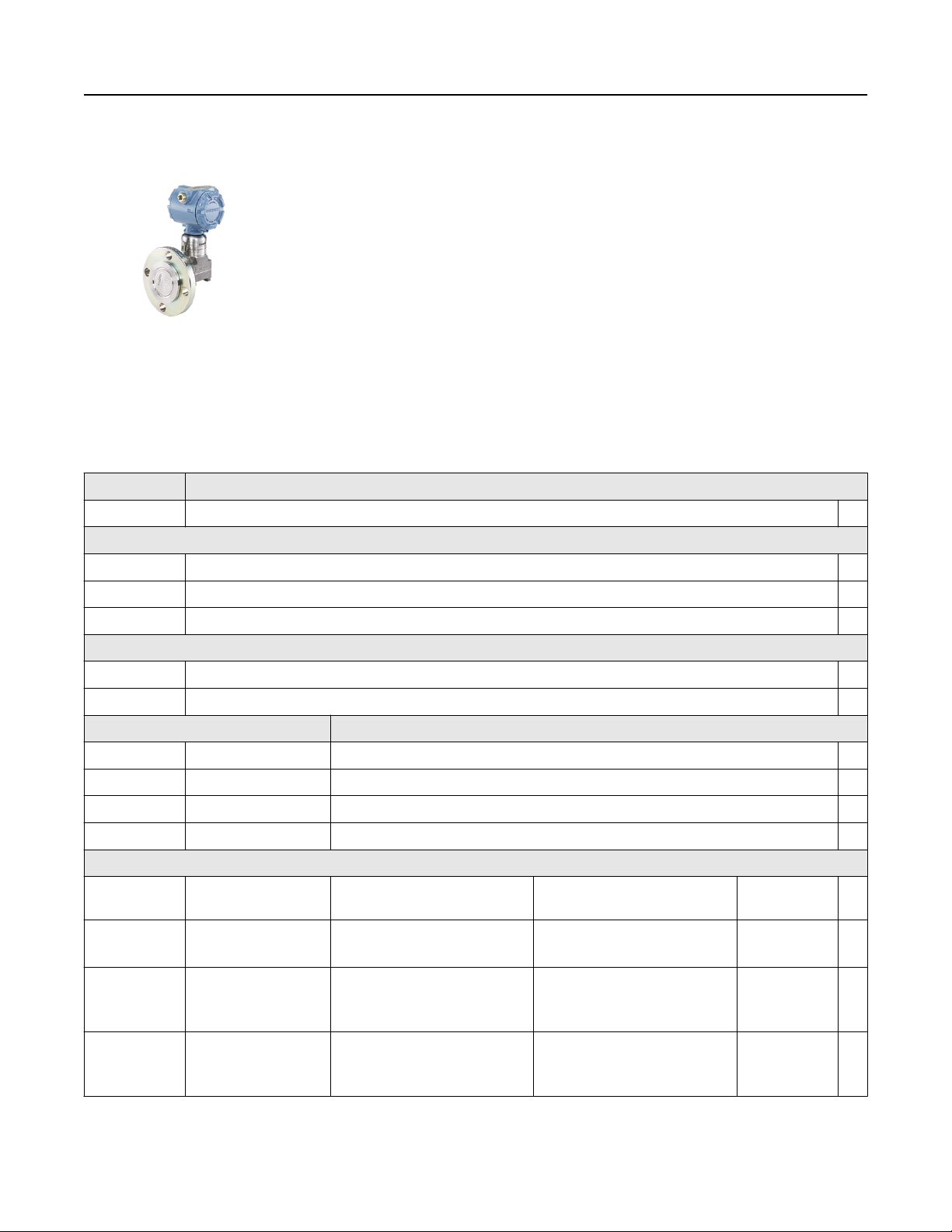
Rosemount™ DP Level Transmitters and 1199
Diaphragm Seal Systems
Applications
■
Level, flow, pressure, interface, density
■
Extreme hot and cold temperatures
■
Corrosive, clogging, or viscous processes
■
Hygienic requirements
■
Special process connections

November 2018
Proven, reliable, and innovative DP Level technologies
To meet your application requirements, Rosemount™ DP Level technologies deliver an unsurpassed product offering that is easy to
specify, order, and install. The offering includes a wide variety of process connections, direct mount or capillary connections, and
materials of construction to address almost any application. If you don’t see what you need listed here, ask us. We can create a
custom engineered solution to meet your needs.
Rosemount Level Transmitters
Level transmitters combine world-class Rosemount pressure instrumentation with direct-mount seals, all in a single integrated
model number.
Rosemount 3051SAL, 3051L, and 2051L Level Transmitters
■
Achieve best-in-class system reliability with all welded systems
■
Wireless configurations provide new data access
■
Connect to virtually any process with a comprehensive offering of
process connections, fill fluids, direct mount or capillary connections,
and materials
■
Quantify and optimize total system performance with QZ option
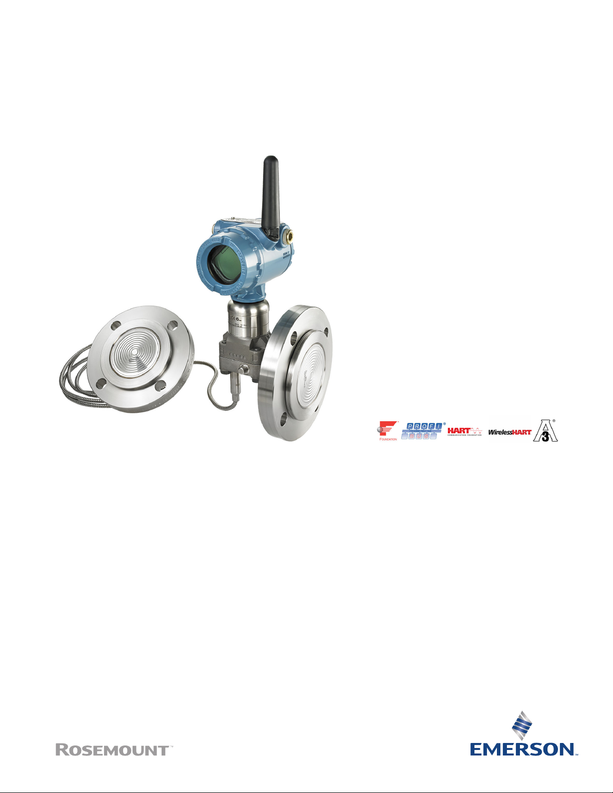
Rosemount Tuned-System™ Assemblies optimize results
Rosemount Tuned-System Assemblies utilize a direct mount seal on the high pressure connection and a remote mount (Capillary)
connection on the low pressure connection. This improves overall performance and installation compared to a traditional Balanced
Seal System.
Contents
Proven, reliable, and innovative DP Level technologies ..................................................................................................................... 2
Rosemount 3051S Electronic Remote Sensor (ERS) System...............................................................................................................5
Rosemount 3051S Scalable™ Level Transmitter................................................................................................................................22
Rosemount™ 3051L Level Transmitter............................................................................................................................................. 51
Rosemount™ 2051L Liquid Level Transmitter................................................................................................................................... 58
Rosemount™ 1199 Direct Mount Seal Systems................................................................................................................................ 65
Rosemount 1199 Remote Mount Seal Systems............................................................................................................................... 71
Flanged seals................................................................................................................................................................................... 77
Threaded seals.................................................................................................................................................................................94
Hygienic seals..................................................................................................................................................................................98
Specialty seals............................................................................................................................................................................... 108
Specifications................................................................................................................................................................................ 113
Product certifications.................................................................................................................................................................... 133
Dimensional Drawings...................................................................................................................................................................175
2 Emerson.com/Rosemount
November 2018
■
Reduce installed costs by 20 percent by eliminating excess capillary and
transmitter mounting hardware
■
Improve performance by up to 30 percent
■
Increase response time by up to 80 percent
■
Reduce risk with up-front quantified performance reports
A. Balanced system with two equal lengths of
capillary
B. Tuned-system assembly with direct mount plus
capillary
Rosemount 3051S Electronic Remote Sensor (ERS)™ System
The Rosemount 3051S ERS System is a digital DP Level architecture that links two Rosemount 3051S Pressure Sensors together
electronically. The pressure sensors are synchronized on a single power loop where the differential pressure, level, and volume are
calculated and transmitted using a standard two-wire 4–20 mA HART® signal.
A digital upgrade to a proven technology
■
■
■
■
Simplified installations and maintenance routines
■
■
■
■
Rosemount 1199 Seal Systems
90 percent improvement in time response
Elimination of temperature effects and measurement drift
Multivariable capabilities including DP, PLO, PHI, volume, and level
Proven Rosemount 3051S Sensor technology
Elimination of wet legs or dry legs
Easy installations without need for heat tracing and insulation
Proactive maintenance and troubleshooting with sensor alerts and diagnostics
Simplified inventories with sensors and standard cable
Seal systems provide a reliable process pressure measurement and
prevent the process medium from contacting the transmitter
diaphragm. Transmitter/diaphragm seal systems should be considered
when:
■
Process temperature is outside of the operating ranges of the
transmitter.
■
Process is corrosive and/or requires specific exotic materials of
construction.
■
Process contains suspended solids or is viscous and is prone to
plugging of connections.
Product Data Sheet 3

November 2018
■
Application requires the use of flush-mount hygienic connections
that facilitates CIP/SIP service.
■
There is a requirement for easier cleaning of the process from the
connections to avoid contamination between batches.
Application flexibility
■
Flanged, threaded, and hygienic process connections
■
Meets industry standards such as EN 1092-1, ANSI/ASME B16.5, JIS B2238, ANSI/ASME B1.20.1, EN 10226-1, GOST 33259-15,
ISO 228-1
■
Variety of fill fluids applications including cold temperature, hot temperature, and hygienic and food grade
■
Three different capillary diameters allow for optimization of accuracy and time response
Reliable system construction
■
Welded design with no threaded connections
■
100 percent helium leak tested
■
Advanced manufacturing techniques ensure air-free, leak-tight system that is stable over time
■
Reliable operation in full vacuum applications
Robust seal design
■
Backup convolutions on the diaphragm protect seal integrity
■
Recessed diaphragms reduce potential for handling damage
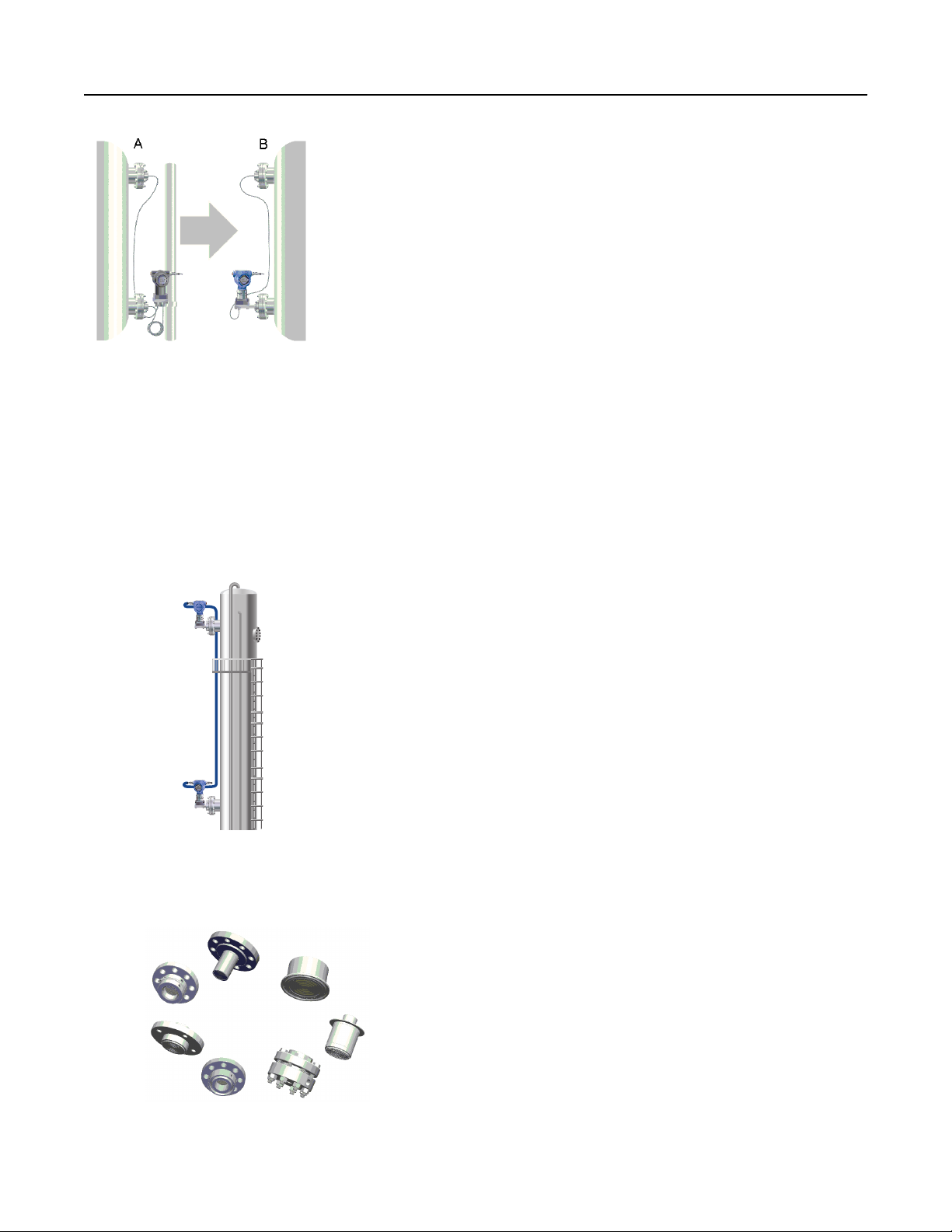
Seal system construction options
Figure 1: Welded-Repairable Construction
■
All connection points welded except gasket between sensor module and transmitter flange
■
Transmitter can be re-used if repair work is required
Figure 2: All Welded (Vacuum) Construction
■
All connection points welded including welded disk over sensor module isolators
■
Ideal for vacuum applications (< 6 psia, 400 mbar-a)
■
Seal system and transmitter are not repairable
4 Emerson.com/Rosemount
November 2018
Rosemount 3051S Electronic Remote Sensor (ERS) System
The Rosemount 3051S ERS System is a flexible, 2-wire 4-20 mA HART architecture that calculates
differential pressure (DP) electronically using two pressure sensors that are linked together with
a non-proprietary electrical wire.
Ideal applications for the Rosemount 3051S ERS System include tall vessels and distillation
columns that have traditionally required long lengths of capillary or impulse piping. When used
in these types of applications, the Rosemount 3051S ERS System can deliver:
■
More accurate and repeatable DP measurements
■
Faster time response
■
Simplified installations
■
Reduced maintenance
How to order
Procedure
1. Choose two Rosemount 3051S ERS Transmitter models. These may be any combination of Rosemount 3051SAM and
Rosemount 3051SAL models.
Example
Rosemount 3051SAM
Coplanar
In-line
Example
Rosemount 3051SAL
Coplanar
In-line
2. Decide which model will be the ERS Primary (4–20 mA loop termination and optional LCD display) and which will be the ERS
Secondary. This will be specified by the “Configuration Type” code in each model number.
Product Data Sheet 5
Example
A. Secondary
B. Primary
3. Specify two full model numbers per the desired configuration.
Example
3051SAL1PG4AA1A1020DFF71DA00M5
3051SAM1ST2A2E11A2A
November 2018
Rosemount 3051SAM Transmitter for ERS Applications
■
Coplanar and in-line sensor module platforms
■
Variety of process connections including threaded NPT, flanges, manifolds, and Rosemount
1199 Remote Seals
■
Available with 15-year stability and 15-year limited warranty
Specification and selection of product materials, options, or components must be made by the
purchaser of the equipment. See Material selection for more information.
Table 1: Rosemount 3051SAM Transmitter for ERS Applications Ordering Information
The starred offerings (★) represent the most common options and should be selected for best delivery. The non-starred offerings
are subject to additional delivery lead time.
Model Transmitter type
3051SAM Scalable ERS Measurement Transmitter
Performance class
1 Ultra: 0.025% span accuracy, 200:1 rangedown, 15-year stability, 15-year limited warranty ★
2 Classic: 0.035% span accuracy, 150:1 rangedown, 15-year stability ★
(1)
4 Enhanced ERS System performance, 15-year stability, 15-year limited warranty ★
6 Emerson.com/Rosemount

November 2018
Table 1: Rosemount 3051SAM Transmitter for ERS Applications Ordering Information (continued)
Configuration type
P ERS - primary ★
S ERS - secondary ★
Pressure module type Pressure sensor type
G Coplanar Gage ★
T In-Line Gage ★
E In-Line Absolute ★
A Coplanar Absolute
Pressure range
(2)
Coplanar gage In-line gage In-line absolute Coplanar absolute
1A N/A –14.7 to 30 psig
(–1,01 to 2,06 bar)
2A –250 to 250 inH2O
(–621,60 to 621,60
–14.7 to 150 psig
(–1,01 to 10,34 bar)
mbar)
3A –393 to 1000 inH2O
(–0,97 to 2,48 bar)
4A –14.2 to 300 psig
(–0,97 to 20,68 bar)
5A –14.2 to 2000 psig
(–0,97 to 137,89
–14.7 to 800 psig
(–1,01 to 55,15 bar)
–14.7 to 4000 psig
(–1,01 to 275,79 bar)
–14.7 to 10000 psig
(–1,01 to 689,47 bar)
bar)
Isolating diaphragm
(3)(4)
2
3
4
5
6
7
(3)
(3)(4)
(4)(5)
(3)(4)
(3)(4)
316L stainless steel (SST) ★
Alloy C-276 ★
Alloy 400
Tantalum
Gold-plated Alloy 400 (includes graphite-filled PTFE O-Ring)
Gold-plated 316L SST
0 to 30 psia
(0 to 2,06 bar)
0 to 150 psia
(0 to 10,34 bar)
0 to 800 psia
(0 to 55,15 bar)
0 to 4000 psia (0 to 275,79
bar)
0 to 10000 psia
(0 to 689,47 bar)
0 to 30 psia
(0 to 2,06 bar)
0 to 150 psia
(0 to 10,34 bar)
0 to 800 psia
(0 to 55,15 bar)
0 to 4000 psia
(0 to 275,79 bar)
N/A ★
★
★
★
★
Process connection
Coplanar module type In-line module type
(6)
A11
A12
A15
(6)
(6)
Assemble to Rosemount 305 Manifold Assemble to Rosemount 306 Manifold ★
Assemble to Rosemount 304 or AMF Manifold with
SST traditional flange
Assemble to Rosemount 304 or AMF manifold to SST
Assemble AMF Manifold to ½-14 NPT female process
connection
N/A ★
★
traditional flange with alloy C-276 drain vents
(6)
A22
Assemble to Rosemount 304 or AMF manifold to SST
N/A ★
coplanar flange
Product Data Sheet 7

November 2018
Table 1: Rosemount 3051SAM Transmitter for ERS Applications Ordering Information (continued)
(6)(7)
B11
Assemble to one Rosemount 1199 Remote
Diaphragm Seal with SST transmitter flange
Assemble to one Rosemount 1199 Remote
Diaphragm
E11 Coplanar flange (CS), ¼–18 NPT, 316 SST drain vents ½ –14 NPT female ★
★
E12 Coplanar flange (SST), ¼–18 NPT, 316 SST drain
N/A ★
vents
(3)
E13
Coplanar flange (Cast C-276), ¼–18 NPT, Alloy C-276
N/A ★
drain vents
E14 Coplanar flange (Cast Alloy 400), ¼–18 NPT, Alloy
N/A ★
400/K-500 drain vents
(3)
E15
Coplanar flange (SST), ¼–18 NPT, Alloy C-276 drain
N/A ★
vents
(3)
E16
Coplanar flange (CS), ¼–18 NPT, Alloy C-276 drain
N/A ★
vents
E21 Coplanar flange (CS), RC ¼, 316 SST drain vents N/A ★
E22 Coplanar flange (SST), RC ¼, 316 SST drain vents N/A ★
(3)
E23
Coplanar flange (Cast C-276), RC ¼, Alloy C-276 drain
N/A ★
vents
E24 Coplanar flange (Cast Alloy 400), RC ¼, alloy 400/
N/A ★
K-500 drain vents
(3)
E25
(3)
E26
F12 Traditional flange (SST), ¼–18 NPT, 316 SST drain
Coplanar flange (SST), RC ¼, Alloy C-276 drain vents N/A ★
Coplanar flange (CS), RC ¼, Alloy C-276 drain vents N/A ★
N/A ★
vents
(3)
F13
Traditional flange (Cast C-276), ¼–18 NPT, Alloy
N/A ★
C-276 drain vents
F14 Traditional flange (Cast Alloy 400), ¼–18 NPT, Alloy
N/A ★
400/K-500 drain vents
(3)
F15
Traditional flange (SST), ¼–18 NPT, Alloy C-276 drain
N/A ★
vents
F22 Traditional flange (SST), RC ¼, 316 SST drain vents N/A ★
(3)
F23
Traditional flange (Cast C-276), RC¼, Alloy C-276
N/A ★
drain vents
F24 Traditional flange (Cast Alloy 400), RC¼, Alloy 400/
N/A ★
K500 drain vents
(3)
F25
Traditional flange (SST), RC ¼, Alloy C-276 drain
N/A ★
vents
F52 DIN-compliant traditional flange (SST), ¼–18 NPT,
N/A ★
316 drain vents, 7 to 16-in. bolting
G11 Vertical mount level flange (SST), 2-in. ANSI Class
G½ A DIN 16288 male (range 1–4 only) ★
150, 316 SST drain vents
G12 Vertical mount level flange (SST), 2-in. ANSI Class
N/A ★
300, 316 SST drain vents
8 Emerson.com/Rosemount

November 2018
Table 1: Rosemount 3051SAM Transmitter for ERS Applications Ordering Information (continued)
G21 Vertical mount level flange (SST), 3-in. ANSI Class
150, 316 SST drain vents
G22 Vertical mount level flange (SST), 3-in. ANSI Class
300, 316 SST drain vents
G31 Vertical mount level flange (SST), DIN-DN 50 PN 40,
316 SST drain vents
G41 Vertical mount level flange (SST), DIN-DN 80 PN 40,
316 SST drain vents
P11 N/A Level flange (SST), 2-in. ANSI Class 150 ★
P12 N/A Level flange (SST), 2-in. ANSI Class 300 ★
P21 N/A Level flange (SST), 3-in. ANSI Class 150 ★
P22 N/A Level flange (SST), 3-in. ANSI Class 300 ★
P31 N/A Level flange (SST), DIN-DN 50 PN 40 ★
F11 Traditional flange (CS), ¼–18 NPT, 316 SST drain
vents
F32 Bottom vent traditional flange (SST), ¼–18 NPT, 316
SST drain vents
F42 Bottom vent traditional flange (SST), RC¼, 316 SST
drain vents
F62 DIN-compliant traditional flange (316 SST), ¼–18
NPT, 316 drain vents, M10 bolting
N/A ★
N/A ★
N/A ★
N/A ★
Non-threaded instrument flange (I-Flange)
N/A
N/A
N/A
F72 DIN-compliant traditional flange (316 SST), ¼–18
NPT, 316 drain vents, M12 bolting
Transmitter output
A 4–20 mA with digital signal based on HART protocol ★
Housing style Material Conduit entry size
Housings for ERS primary - configuration type code P
1A Plantweb™ housing Aluminum ½–14 NPT ★
1B Plantweb housing Aluminum M20 x 1.5 (CM 20) ★
1J Plantweb housing SST ½–14 NPT ★
1K Plantweb housing SST M20 x 1.5 (CM 20) ★
2E Junction box with remote display
output
2F Junction box with remote display
output
2M Junction box with remote display
output
1C Plantweb housing Aluminum G½
1L Plantweb housing SST G½
2G Junction box with remote display
output
Aluminum ½–14 NPT ★
Aluminum M20 x 1.5 (CM 20) ★
SST ½–14 NPT ★
Aluminum G½
N/A
Product Data Sheet 9

November 2018
Table 1: Rosemount 3051SAM Transmitter for ERS Applications Ordering Information (continued)
Housings for ERS secondary - configuration type code S
2A Junction box Aluminum ½–14 NPT ★
2B Junction box Aluminum M20 x 1.5 (CM 20) ★
2J Junction box SST ½–14 NPT ★
2C Junction box Aluminum G½
Options (include with selected model number)
Extended product warranty
WR3 3-year limited warranty ★
WR5 5-year limited warranty ★
ERS connection cable
R02 25 ft. (7,62 m) of ERS cable (gray color)
R05 50 ft. (15,2 m) of ERS cable (gray color) ★
R10 100 ft. (30,5 m) of ERS cable (gray color) ★
R15 150 ft. (45,72 m) of ERS cable (gray color) ★
(8)
R20
R22
(9)
200 ft. (60,96 m) of ERS cable (gray color)
225 ft. (68,58 m) of ERS cable (gray color)
R30 300 ft. (91,44 m) of ERS cable (gray color)
R40 400 ft. (121,92 m) of ERS cable (gray color)
R50 500 ft. (152,4 m) of ERS cable (gray color)
H02 25 ft. (7,62 m) of ERS cable (blue color)
H05 50 ft. (15,2 m) of ERS cable (blue color)
H10 100 ft. (30,5 m) of ERS cable (blue color)
H15 150 ft. (45,7 m) of ERS cable (blue color)
(8)
H20
H22
(9)
200 ft. (60,96 m) of ERS cable (blue color)
225 ft. (68,58 m) of ERS cable (blue color)
J02 25 ft. (7,62 m) of ERS armored cable
J05 50 ft. (15,2 m) of ERS armored cable
J07 75 ft. (22,8 m) of ERS armored cable
J10 100 ft. (30,5 m) of ERS armored cable
(9)
J12
125 ft. (38,1 m) of ERS armored cable
Mounting bracket
(4)
B1
B2
B3
(4)
(4)
Traditional flange bracket, CS, 2-in. pipe ★
Traditional flange bracket, CS, panel ★
Traditional flange flat bracket, CS, 2-in. pipe ★
B4 Bracket, all SST, 2-in. pipe and panel ★
(4)
B7
Traditional flange bracket, B1 with SST bolts ★
10 Emerson.com/Rosemount

November 2018
Table 1: Rosemount 3051SAM Transmitter for ERS Applications Ordering Information (continued)
(4)
B8
B9
BA
BC
(4)
(4)
(4)
Traditional flange bracket, B2 with SST bolts ★
Traditional flange bracket, B3 with SST bolts ★
Traditional flange bracket, B1, all SST ★
Traditional flange bracket, B3, all SST ★
Special configuration (software)
(10)
C1
Customer software configuration (Configuration Data Sheet must be completed) ★
C3 Gage pressure calibration on Rosemount 3051SAM A4 only ★
(10)
C4
C5
C6
C7
C8
(10)
(10)
(10)
(10)
NAMUR alarm and saturation levels, high alarm ★
NAMUR alarm and saturation levels, low alarm ★
Custom alarm and saturation levels, high alarm (requires C1 and Configuration Data Sheet) ★
Custom alarm and saturation levels, low alarm (requires C1 and Configuration Data Sheet) ★
Low alarm (standard Rosemount alarm and saturation levels) ★
Special configuration (hardware)
(11)
D2
D4
D5
D7
D9
(12)
(11)
(11)
(11)
¼–14 NPT flange adapters ★
External ground screw assembly ★
Delete transmitter drain/vent valves (install plugs) ★
Coplanar flange without drain/vent ports
RC ½ flange adapters
Product certifications
E1 ATEX Flameproof ★
I1 ATEX Intrinsic Safety ★
N1 ATEX Type n ★
K1 ATEX Flameproof and Intrinsically Safe, Type n, Dust ★
ND ATEX Dust ★
E4 TIIS Flameproof ★
E5 FM Explosion-proof, Dust Ignition-proof ★
I5 FM Intrinsically Safe, Division 2 ★
K5 FM Explosion-proof, Dust Ignition-proof, Intrinsically Safe, Division 2 ★
(13)
E6
CSA Explosion-proof, Dust Ignition-proof, Division 2 ★
I6 CSA Intrinsically Safe ★
(13)
K6
CSA Explosion-proof, Dust Ignition-proof, Intrinsically Safe, Division 2 ★
E7 IECEx Flameproof ★
I7 IECEx Intrinsic Safety ★
N7 IECEx Type n ★
K7 IECEx Flameproof, Intrinsic Safety, Type n ★
E2 INMETRO Flameproof ★
Product Data Sheet 11

November 2018
Table 1: Rosemount 3051SAM Transmitter for ERS Applications Ordering Information (continued)
I2 INMETRO Intrinsically Safe ★
K2 INMETRO Flameproof, Intrinsic Safety, Type n ★
E3 China Flameproof ★
I3 China Intrinsic Safety, Dust Ignition-proof ★
EP Korea Flameproof ★
IP Korea Intrinsic Safety ★
KP Korea Flameproof, Intrinsic Safety ★
EM Technical Regulations Customs Union (EAC) Flameproof ★
IM Technical Regulations Customs Union (EAC) Intrinsic Safety ★
KM Technical Regulations Customs Union (EAC) Flameproof, Intrinsic Safety ★
(13)
KA
KB
(13)
ATEX and CSA Flameproof, Intrinsically Safe, Division 2 ★
FM and CSA Explosion-proof, Dust Ignition-proof, Intrinsically Safe, Division 2 ★
KC FM and ATEX Explosion-proof, Intrinsically Safe, Division 2 ★
(13)
KD
FM, CSA, and ATEX Explosion-proof, Intrinsically Safe ★
Shipboard approvals
SBS American Bureau of Shipping (ABS) Type Approval ★
SBV Bureau Veritas (BV) Type Approval ★
SDN Det Norske Veritas (DNV) Type Approval ★
SLL Lloyds Register (LR) Type Approval ★
Calibration certification
Q4 Calibration certificate ★
QP Calibration certificate and tamper evident seal ★
Material traceability certification
Q8 Material traceability certification per EN 10204 3.1 ★
Quality certification for safety
QS Prior-use certificate of FMEDA Data ★
QT Safety certified to IEC 61508 with certificate of FMEDA data ★
Surface finish certification
Q16 Surface finish certification for hygienic remote seals ★
Toolkit performance reports
(14)
QZ Remote seal system performance calculation report ★
Terminal blocks
(15)
T1 Transient terminal block ★
Sensor fill fluid
(16)
L1 Inert sensor fill fluid ★
12 Emerson.com/Rosemount

November 2018
Table 1: Rosemount 3051SAM Transmitter for ERS Applications Ordering Information (continued)
O-ring
L2 Graphite-filled PTFE O-ring ★
Bolting material
(11)
L4 Austenitic 316 SST bolts ★
(3)
L5
ASTM A 193, Grade B7M bolts ★
L6 Alloy K-500 bolts ★
(3)
L7
ASTM A 453, Class D, Grade 660 bolts ★
L8 ASTM A 193, Class 2, Grade B8M bolts ★
Display type (ERS primary only)
(10)
M5 Plantweb LCD display ★
(17)
M7
Remote mount LCD display and interface, Plantweb housing, no cable, SST bracket ★
M8 Remote mount LCD display and interface, Plantweb housing, 50 ft. (15,2 m) cable, SST bracket ★
M9 Remote mount LCD display and interface, Plantweb housing, 100 ft. (30,5 m) cable, SST bracket ★
Pressure testing
P1 Hydrostatic testing with certificate
Special cleaning
(11)
P2 Cleaning for special services
P3 Cleaning for less than 1 PPM Chlorine/Fluorine
NACE® certificate
(3)
Q15 Certificate of compliance to NACE MR0175/ISO 15156 for wetted materials ★
Q25 Certificate of compliance to NACE MR0103 for wetted materials ★
Typical model number: 3051SAM 1 S T 2A 2 E11 A 2A
See “Specifications” section for more detail. The Rosemount 3051S ERS System offers three performance class options; Classic, Ultra, and
(1)
Enhanced ERS system performance. The Classic and Ultra performance classes are suited to lower static pressure and stable temperature
conditions. The Enhanced ERS system performance class provides better performance across temperature (–40 to 185 °F) with improved
performance at higher static pressure.
The pressure range should be specified based on the maximum static pressure, not differential pressure.
(2)
Materials of construction comply with metallurgical requirements highlighted within NACE MR 0175/ISO 15156 for sour oil field production
(3)
environments. Environmental limits apply to certain materials. Consult latest standard for details. Selected materials also conform to NACE MR
0103 for sour refining environments. Order with Q15 or Q25 to receive a NACE certificate.
Not available with pressure sensor/module codes T or E.
(4)
Tantalum diaphragm material is only available with Pressure Sensor/Module code G.
(5)
“Assemble to” items are specified separately and require a completed model number.
(6)
Consult an Emerson™ representative for performance specifications.
(7)
Maximum cable distance for SIS installations. See Rosemount 3051S ERS Reference Manual for more information.
(8)
Maximum cable distance for IS (Intrinsically safe) installations. Other options may not be valid at longer distances.
(9)
Not available with Configuration Type code S.
(10)
Not available with Process Connection code A11.
(11)
This assembly is included with options E1, N1, K1, ND, E4, E7, N7, K7, E2, KA, KC, KD, K2, T1, EP, and KP.
(12)
Not available with M20 or G½ conduit entry size.
(13)
The QZ report quantifies the performance of the entire ERS system. One report is provided per ERS system. The QZ option is specified on the
(14)
primary transmitter (configuration type code P).
Not available with configuration type code S.
(15)
Silicone fill fluid is standard.
(16)
See the Rosemount 3051S Reference Manual for cable requirements. Contact an Emerson representative for additional information.
(17)
Product Data Sheet 13
November 2018
Rosemount 3051SAL Transmitter for ERS Applications
■
Integrated transmitter and direct mount seal in a single model number
■
Variety of process connections including flanged, threaded, and hygienic remote seals
■
Available with 15-year limited warranty
Specification and selection of product materials, options, or components must be made by the
purchaser of the equipment. See Material selection for more information .
A Rosemount 3051SAL Scalable ERS Level Transmitter consists of three parts. First, specify the transmitter model codes found in
Table 2 . Then, specify a direct mount seal found here: Diaphragm seals for Rosemount 3051SAL. Finish the model number by
specifying all desired options from the "Options" section of Table 2.
Table 2: Rosemount 3051SAL Transmitter for ERS Applications Ordering Information
The starred offerings (★) represent the most common options and should be selected for best delivery. The non-starred offerings
are subject to additional delivery lead time.
Model Transmitter type
3051SAL Scalable level transmitter
Performance class
(1)
1 Ultra: 0.055% span accuracy, 150:1 rangedown, 15-year limited warranty ★
2 Classic: 0.065% span accuracy, 150:1 rangedown ★
4 Enhanced ERS system performance, 15-year limited warranty ★
Configuration type
P ERS - primary ★
S ERS - secondary ★
Pressure module type Pressure sensor type
G Coplanar Gage ★
T In-line Gage ★
E In-line Absolute ★
A Coplanar Absolute
Pressure range
Coplanar gage In-line gage In-line absolute Coplanar
1A N/A –14.7 to 30 psig (–1,01 to 2,06
2A –250 to 250 inH2O (–
(2)
621,60 to 621,60
mbar)
bar)
–14.7 to 150 psig (–1,01 to
10,34 bar)
absolute
0 to 30 psia (0 to 2,06 bar) 0 to 30 psia (0
to 2,06 bar)
0 to 150 psia (0 to 10,34 bar) 0 to 150 psia
(0 to 10,34
bar)
★
★
3A –393 to 1000 inH2O
(–0,97 to 2,48 bar)
–14.7 to 800 psig (–1,01 to
55,15 bar)
0 to 800 psia (0 to 55,15 bar) 0 to 800 psia
(0 to 55,15
bar)
★
14 Emerson.com/Rosemount
November 2018
Table 2: Rosemount 3051SAL Transmitter for ERS Applications Ordering Information (continued)
4A –14.2 to 300 psig(–
0,97 to 20,68 bar)
–14.7 to 4000 psig (–1,0 to
275,79 bar)
0 to 4000 psia (0 to 275,79 bar) 0 to 4000 psia
(0 to 275,79
bar)
5A –14.2 to 2000 psig (–
0,97 to 137,89 bar)
–14.7 to 10000 psig (–1,01 to
689,47 bar)
0 to 10000 psia (0 to 689,47
bar)
N/A ★
Transmitter output
A 4–20 mA with digital signal based on HART Protocol ★
Housing style Material Conduit entry size
Housings for ERS primary - configuration type code P
1A Plantweb housing Aluminum ½–14 NPT ★
1B Plantweb housing Aluminum M20 x 1.5 (CM 20) ★
1J Plantweb housing SST ½–14 NPT ★
1K Plantweb housing SST M20 x 1.5 (CM 20) ★
2E Junction box with remote display
Aluminum ½–14 NPT ★
output
2F Junction box with remote display
Aluminum M20 x 1.5 (CM 20) ★
output
2M Junction box with remote display
SST ½–14 NPT ★
output
★
1C Plantweb housing Aluminum G½
1L Plantweb housing SST G½
2G Junction box with remote display
Aluminum G½
output
Housings for ERS secondary - configuration type code S
2A Junction box Aluminum ½–14 NPT ★
2B Junction box Aluminum M20 x 1.5 (CM 20) ★
2J Junction box SST ½–14 NPT ★
2C Junction box Aluminum G½
Seal system type
(3)
Coplanar pressure module type
1 Single direct mount
Welded-repairable ★
seal system
2 Single direct mount
All welded ★
seal system
In-line pressure module type
1 Single direct mount
All welded ★
seal system
High side connection type
Single direct mount seal system (between transmitter and remote seal)
0 No extension ★
Product Data Sheet 15
November 2018
Table 2: Rosemount 3051SAL Transmitter for ERS Applications Ordering Information (continued)
2 2-in. (50 mm) extension ★
4 4-in. (100 mm) extension ★
(4)
5
6
7
(5)
(5)(6)
Thermal Optimizer ★
Thermal Range Expander - Silicone 200 secondary fill fluid ★
Thermal Range Expander - SYLTHERM™ XLT secondary fill fluid ★
Low side connection type (reference pressure connection)
Single direct mount seal system
00 None (In-line style sensor) ★
20 316L SST isolator/SST transmitter flange ★
30 Alloy C-276 isolator/SST transmitter flange ★
Seal fill fluid Specific
gravity at 77
°F (25 °C)
Temperature limits
No extension 2-in. (50 mm)
(7)(8)
extension
4-in. (100
mm)
Thermal Range
Expander
(9)
extension
D Silicone 200 0.934 –49 to 401 °F (–45 to 205 °C) N/A ★
F Silicone 200 for
vacuum applications
0.934 For use in vacuum applications below 14.7 psia (1 bar-a), refer to
vapor pressure curves in Rosemount DP Level Fill Fluid
Specification Technical Note.
(10)
J
(10)
Q
Tri-Therm 300 0.795 –40 to 401 °F
(–40 to 205 °C)
Tri-Therm 300 for
vacuum applications
0.795 For use in vacuum applications below 14.7 psia (1 bar-a), refer to
vapor pressure curves in Rosemount DP Level Fill Fluid
–40 to 464 °F
(–40 to 240 °C)
–40 to 572 °F
(–40 to 300 °C)
N/A ★
Specification Technical Note.
L Silicone 704 1.07 32 to 401 °F (0
to 205 °C)
C Silicone 704 for
vacuum applications
1.07 For use in vacuum applications below 14.7 psia (1 bar-a), refer to
vapor pressure curves in Rosemount DP Level Fill Fluid
32 to 464 °F (0
to 240 °C)
32 to 572 °F (0
to 300 °C)
Up to 599 °F
(315 °C)
Specification Technical Note.
R Silicone 705 1.09 68 to 401 °F
(20 to 205 °C)
V Silicone 705 for
vacuum applications
1.09 For use in vacuum applications below 14.7 psia (1 bar-a), refer to
vapor pressure curves in Rosemount DP Level Fill Fluid
68 to 464 °F
(20 to 240 °C)
68 to 572 °F
(20 to 300 °C)
Up to 698 °F
(370 °C)
Specification Technical Note.
A SYLTHERM XLT 0.85 –157 to 293 °F (–105 to 145 °C) N/A ★
H Inert (Halocarbon) 1.85 –49 to 320 °F (–45 to 160 °C) N/A ★
(10)(11)
G
(10)
N
Glycerin and water 1.13 5 to 203 °F (–15 to 95 °C) N/A ★
Neobee® M-20 0.94 5 to 401 °F (–
5 to 437 °F (–15 to 225 °C) N/A ★
15 to 205 °C)
(10)(11)
P
Propylene glycol and
1.02 5 to 203 °F (–15 to 95 °C) N/A ★
water
(12)
Y
UltraTherm™ 805 1.20 N/A Up to 770 °F
( 410 °C)
(13)
★
★
★
★
★
★
★
16 Emerson.com/Rosemount
November 2018
Table 2: Rosemount 3051SAL Transmitter for ERS Applications Ordering Information (continued)
(12)
Z
UltraTherm 805 for
vacuum applications
1.20 For use in vacuum applications below 14.7 psia (1 bar-a), refer to
vapor pressure curves in Rosemount DP Level Fill Fluid
Specification Technical Note.
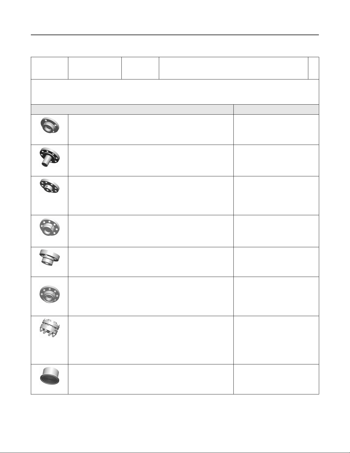
Continue specifying a completed model number by choosing a remote seal type below:
Seal style Process connections
FF Flush Flanged Seal 2-in./DN 50/50A
3-in./DN 80/80A
4-in./ DN 100/100A
EF Extended Flanged Seal 3-in./DN 80/80A
4-in./DN 100/100A
RF Remote Flanged Seal ½-in.
¾-in
1-in./DN 25/25A
1½-in./DN 40/40A
★
PF Pancake Seal 2-in./DN 50/50A
3-in./DN 80/80A
FC Flush Flanged Seal - Ring Type Joint (RTJ) gasket surface 2-in.
3-in.
RC Remote Flanged Seal - Ring Type Joint (RTJ) gasket surface ½-in.
¾-in
1-in.
1½-in.
RT Remote Threaded Seal ¼ –18 NPT
½ –14 NPT
¾ –14 NPT
1–11.5 NPT
1¼–11.5 NPT
SC Hygienic Tri-Clamp Seal 1½-in.
2-in.
3-in.
Product Data Sheet 17
November 2018
Table 2: Rosemount 3051SAL Transmitter for ERS Applications Ordering Information (continued)
SS Hygienic Tank Spud Seal 4-in.
Options (include with selected model number)
Extended product warranty
WR3 3-year limited warranty ★
WR5 5-year limited warranty ★
ERS connection cable
(14)
R02 25 ft. (7,62 m) of ERS cable (gray color)
R05 50 ft. (15,2 m) of ERS cable (gray color) ★
R10 100 ft. (30,5 m) of ERS cable (gray color) ★
R15 150 ft. (45,72 m) of ERS cable (gray color) ★
(15)
R20
R22
(16)
200 ft. (60,96 m) of ERS cable (gray color)
225 ft. (68,58 m) of ERS cable (gray color)
R30 300 ft. (91,44 m) of ERS cable (gray color)
R40 400 ft. (121,92 m) of ERS cable (gray color)
R50 500 ft. (152,4 m) of ERS cable (gray color)
H02 25 ft. (7,62 m) of ERS cable (blue color)
H05 50 ft. (15,2 m) of ERS cable (blue color)
H10 100 ft. (30,5 m) of ERS cable (blue color)
H15 150 ft. (45,7 m) of ERS cable (blue color)
(15)
H20
H22
(16)
200 ft. (60,96 m) of ERS cable (blue color)
225 ft. (68,58 m) of ERS cable (blue color)
J02 25 ft. (7,62 m) of armored ERS cable
J05 50 ft. (15,2 m) of armored ERS cable
J07 75 ft. (22,8 m) of armored ERS cable
J10 100 ft. (30,5 m) of armored ERS cable
(16)
J12
Software configuration
125 ft. (38,1 m) of armored ERS cable
(17)
C1 Custom software configuration (requires Configuration Data Sheet) ★
Gage pressure calibration
C3 Gage pressure calibration on Rosemount 3051SAL A4 only ★
Alarm limit
(17)
C4 NAMUR alarm and saturation levels, high alarm ★
C5 NAMUR alarm and saturation levels, low alarm ★
18 Emerson.com/Rosemount

November 2018
Table 2: Rosemount 3051SAL Transmitter for ERS Applications Ordering Information (continued)
C6 Custom alarm and saturation levels, high alarm (requires C1 and Configuration Data Sheet) ★
C7 Custom alarm and saturation levels, low alarm (requires C1 and Configuration Data Sheet) ★
C8 Low alarm (standard Rosemount alarm and saturation levels) ★
Ground screw
(18)
D4 External ground screw assembly ★
Conduit plug
DO 316 SST conduit plug ★
Product certifications
E1 ATEX Flameproof ★
I1 ATEX Intrinsic Safety ★
N1 ATEX Type n ★
K1 ATEX Flameproof and Intrinsically Safe, Type n, Dust ★
ND ATEX Dust ★
E4 TIIS Flameproof ★
E5 FM Explosion-proof, Dust Ignition-proof ★
I5 FM Intrinsically Safe, Division 2 ★
K5 FM Explosion-proof, Dust Ignition-proof, Intrinsically Safe, Division 2 ★
(19)
E6
CSA Explosion-proof, Dust Ignition-proof, Division 2 ★
I6 CSA Intrinsically Safe ★
(19)
K6
CSA Explosion-proof, Dust Ignition-proof, Intrinsically Safe, Division 2 ★
E7 IECEx Flameproof ★
I7 IECEx Intrinsic Safety ★
N7 IECEx Type n ★
K7 IECEx Flameproof, Intrinsic Safety, Type n ★
E2 INMETRO Flameproof ★
I2 INMETRO Intrinsically Safe ★
K2 INMETRO Flameproof, Intrinsic Safety, Type n ★
EP Korea Flameproof ★
E3 China Flameproof ★
I3 China Intrinsic Safety, Dust Ignition-proof ★
IP Korea Intrinsic Safety ★
KP Korea Flameproof, Intrinsic Safety ★
EM Technical Regulations Customs Union (EAC) Flameproof ★
IM Technical Regulations Customs Union (EAC) Intrinsic Safety ★
IN Technical Regulations Customs Union (EAC) FISCO Intrinsic Safety ★
KM Technical Regulations Customs Union (EAC) Flameproof, Intrinsic Safety ★
Product Data Sheet 19

November 2018
Table 2: Rosemount 3051SAL Transmitter for ERS Applications Ordering Information (continued)
(19)
KA
KB
(19)
ATEX and CSA Flameproof, Intrinsically Safe, Division 2 ★
FM and CSA Explosion-proof, Dust Ignition-proof, Intrinsically Safe, Division 2 ★
KC FM and ATEX Explosion-proof, Intrinsically Safe, Division 2 ★
(19)
KD
FM, CSA, and ATEX Explosion-proof, Intrinsically Safe ★
Shipboard approvals
SBS American Bureau of Shipping (ABS) Type Approval ★
SBV Bureau Veritas (BV) Type Approval ★
SDN Det Norske Veritas (DNV) Type Approval ★
SLL Lloyds Register (LR) Type Approval ★
Sensor fill fluid
(20)
L1 Inert sensor fill fluid ★
O-ring
L2 Graphite-filled PTFE O-ring ★
Bolting material
L4 Austenitic 316 SST bolts ★
Display type (ERS primary only)
(17)
M5 Plantweb LCD display ★
(21)
M7
Remote mount LCD display and interface, Plantweb housing, no cable, SST bracket ★
M8 Remote mount LCD display and interface, Plantweb housing, 50 ft. (15,2 m) cable, SST bracket ★
M9 Remote mount LCD display and interface, Plantweb housing, 100 ft. (30,5 m) cable, SST bracket ★
Pressure testing
P1 Hydrostatic testing with certificate
Special cleaning
P2 Cleaning for special services
P3 Cleaning for Less than 1 PPM Chlorine/Fluorine
Calibration certification
Q4 Calibration certificate ★
QP Calibration certificate with tamper evident seal ★
Material traceability certification
Q8 Material traceability certification per EN 10204 3.1 ★
Quality certification for safety
QS Prior-use certificate of FMEDA Data ★
QT Safety certified to IEC 61508 with certificate of FMEDA data ★
Toolkit performance reports
(22)
QZ Remote seal system performance calculation report ★
20 Emerson.com/Rosemount

November 2018
Table 2: Rosemount 3051SAL Transmitter for ERS Applications Ordering Information (continued)
Transient protection
(17)
T1 Transient terminal block ★
NACE® certificate
(23)
Q15 Certificate of compliance to NACE MR0175/ISO 15156 for wetted materials ★
Q25 Certificate of compliance to NACE MR0103 for wetted materials ★
Typical model number: 3051SAL 1 P G 4A A 1A 1 0 20 D FF 7 1 DA 0 0 M5
See “Specifications” section for more detail. The Rosemount 3051S ERS System offer three performance class options; Classic, Ultra, and
(1)
Enhanced ERS system performance. The Classic and Ultra performance classes are suited to lower static pressure and stable temperature
conditions. The Enhanced ERS system performance class provides better performance across temperature (–40 to 185 °F) with improved
performance at higher static pressure.
Not suitable for vacuum applications.
(2)
See Seal system type in Rosemount DP Level Product Data Sheet for more detail.
(3)
Maximum working pressure (MWP) of the Thermal Optimizer is 4000 psi (275 bar). See Figure 6, Figure 7, or Table 52 for Thermal Optimizer
(4)
temperature limits.
Maximum working pressure (MWP) of the Thermal Range Expander is 3750 psi (258,6 bar).
(5)
Thermal Range Expander with SYLTHERM XLT secondary fill fluid is not recommended for use in vacuum applications below 6 psia (400 mbar-a).
(6)
At ambient pressure of 14.7 psia (1 bar-a) and ambient temperature of 70 °F (21 °C). Temperature limits are reduced in vacuum service and may
(7)
be limited by seal selection.
Due to heat transfer to the transmitter, the maximum process temperature of the transmitter will be de-rated if ambient or process temperatures
(8)
exceed 185 °F (85 °C). Consult Instrument Toolkit™ to verify the application.
For complete process and ambient temperature limits, see Thermal Range Expander temperature operating range.
(9)
This is a food grade fill fluid.
(10)
Not suitable for vacuum applications.
(11)
Only available with Thermal Range Expander.
(12)
UltraTherm 805 supports maximum design temperature of 454 °C (850 °F). Design temperature rating is for non-continuous use with a
(13)
cumulative exposure time less of than 12 hours.
The pressure range should be specified based on the maximum static pressure, not differential pressure.
(14)
Maximum cable distance for SIS installations. See "Safety Instrumented Systems (SIS) Certification" section of Rosemount 3051S ERS Reference
(15)
Manual for more information.
Maximum cable distance for IS (Intrinsically safe) installations. Other options may not be valid at longer distances.
(16)
Not available with configuration type code S.
(17)
This assembly is included with options EP, KP, E1, N1, K1, ND, E4, E7, N7, K7, E2, KA, KC, KD, K2, T1, E3, EM, KM.
(18)
Not available with M20 or G½ conduit entry size.
(19)
Silicone fill fluid is standard.
(20)
See the Rosemount 3051S Reference Manual for cable requirements. Contact an Emerson representative for additional information.
(21)
The QZ report quantifies the performance of the entire ERS system. One report is provided per ERS system. The QZ option is specified on the
(22)
primary transmitter (configuration type code P).
Materials of construction comply with metallurgical requirements highlighted within NACE MR 0175/ISO 15156 for sour oil field production
(23)
environments. Environmental limits apply to certain materials. Consult latest standard for details. Selected materials also conform to NACE MR
0103 for sour refining environments. UltraTherm 805 supports maximum design temperature of 850 °F (454 °C). Design temperature rating is for
non-continuous use with a cumulative exposure time less of than 12 hours.
Product Data Sheet 21

November 2018
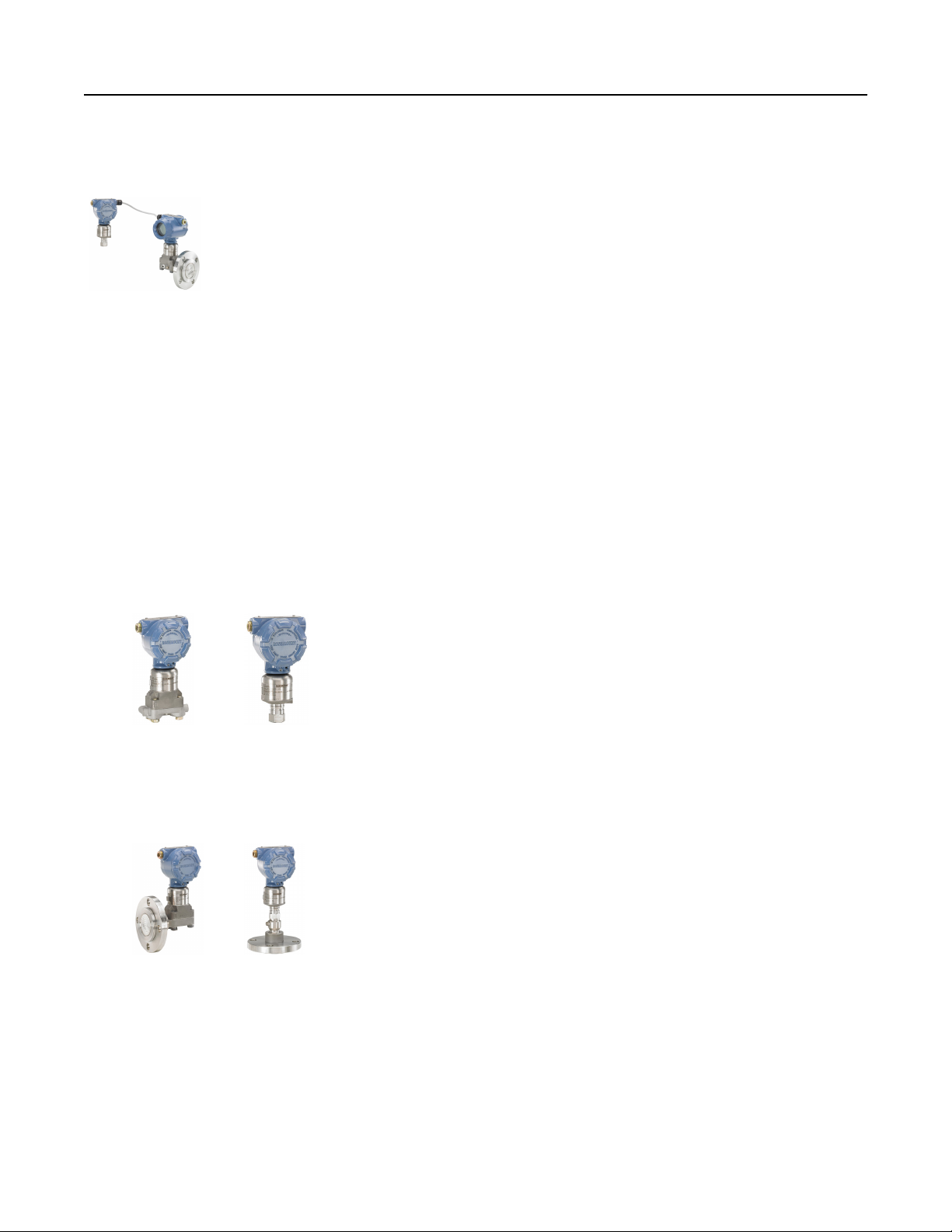
Rosemount 3051S Scalable™ Level Transmitter
Rosemount 3051S Scalable Level Transmitters combine the features and benefits of a high-performance Rosemount 3051S with
the durability and reliability of diaphragm seals all in a single model number.
Rosemount
3051SAL In-line
with “FF” Flanged
Seal
Product features and capabilities include:
■
Variety of process connections including flanged, threaded, and hygienic seals
■
Quantified performance for the entire transmitter/seal assembly (QZ option)
■
HART, FOUNDATION™ Fieldbus, and wireless protocols
Rosemount
3051SAL Coplanar
with “SS” Hygienic
Tank Spud Seal
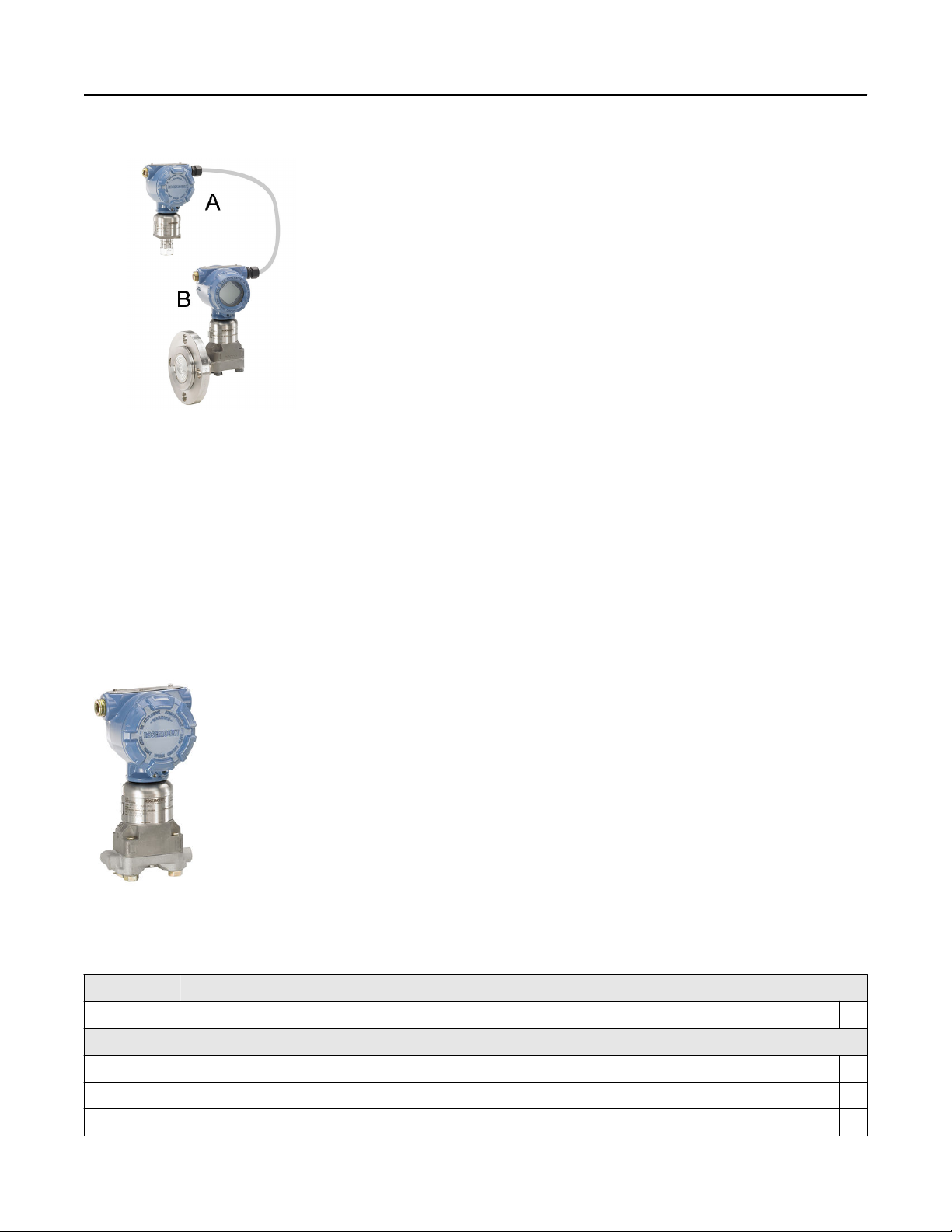
Rosemount 3051SAL Tuned-System
™
Assembly with Thermal Range Expander
Rosemount 3051SAL Balanced System
Rosemount 3051SAL Scalable Level Transmitter
Specification and selection of product materials, options, or components must be made by the purchaser of the equipment. See
Material selection for more information.
A Rosemount 3051SAL Transmitter consists of three parts. First, specify the transmitter model codes found in Table 3. Then, specify
a direct mount seal found here: Diaphragm seals for Rosemount 3051SAL. Finish the model number by specifying all desired
options from the "Options" section of Table 3.
Table 3: Rosemount 3051SAL Scalable Level Transmitter Ordering Information
The starred offerings (★) represent the most common options and should be selected for best delivery. The non-starred offerings
are subject to additional delivery lead time.
Model Transmitter type
3051SAL Scalable level transmitter
Performance class
(1)
1 Ultra: 0.055% span accuracy, 150:1 rangedown, 15-year limited warranty ★
2 Classic: 0.065% span accuracy, 150:1 rangedown ★
Configuration type
C Liquid level transmitter ★
Pressure module type
D Coplanar Differential ★
G Coplanar Gage ★
22 Emerson.com/Rosemount
November 2018
Table 3: Rosemount 3051SAL Scalable Level Transmitter Ordering Information (continued)
T In-line Gage ★
E In-line Absolute ★
A Coplanar Absolute
Pressure range
Coplanar DP Coplanar Gage In-line Gage In-line Absolute Coplanar Absolute
1A N/A N/A –14.7 to 30
psig (–1,01 to
0 to 30 psia (0
to 2,06 bar)
0 to 30 psia (0 to 2,06 bar) ★
2,06 bar)
2A –250 to 250
inH2O (–
621,60 to
621,60 mbar)
3A –1000 to 1000
inH2O (–2,48
to 2,48 bar)
4A –300 to 300 psi
(–20,68 to
20,68 bar)
5A –2000 to 2000
psi (–137,89 to
137,89 bar)
–250 to 250
inH2O (–
621,60 to
621,60 mbar)
–393 to 1000
inH2O (–0,97
to 2,48 bar)
–14.2 to 300
psig (–0,97 to
20,68 bar)
–14.2 to 2000
psig (–0,97 to
137,89 bar)
–14.7 to 150
psig (–1,01 to
10,34 bar)
–14.7 to 800
psig (–1,01 to
55,15 bar)
–14.7 to 4000
psig (–1,01 to
275,79 bar)
–14.7 to 10000
psig (–1,01 to
689,47 bar)
0 to 150 psia (0
to 10,34 bar)
0 to 800 psia (0
to 55,15 bar)
0 to 4000 psia
(0 to 275,79
bar)
0 to 10000 psia
(0 to 689,47
bar)
0 to 150 psia (0 to 10,34 bar) ★
0 to 800 psia (0 to 55,15 bar) ★
0 to 4000 psia (0 to 275,79 bar) ★
N/A ★
Transmitter output
A 4–20 mA with digital signal based on HART protocol ★
(2)
F
(3)
X
FOUNDATION Fieldbus™ protocol ★
Wireless (requires wireless options and wireless Plantweb housing) ★
Housing style Material Conduit entry
1A Plantweb housing Aluminum ½–14 NPT ★
1B Plantweb housing Aluminum M20 x 1.5 ★
1J Plantweb housing SST ½–14 NPT ★
1K Plantweb housing SST M20 x 1.5 ★
2A Junction box housing Aluminum ½–14 NPT ★
2B Junction box housing Aluminum M20 x 1.5 ★
2E Junction box with output for remote interface Aluminum ½–14 NPT ★
2F Junction box with output for remote interface Aluminum M20 x 1.5 ★
2J Junction box housing SST ½–14 NPT ★
(4)
5A
5J
7J
(4)
(5)
Wireless Plantweb housing Aluminum ½–14 NPT ★
Wireless Plantweb housing SST ½–14 NPT ★
Quick connect (a size mini, 4-pin male
SST N/A ★
termination)
1C Plantweb housing Aluminum G½
Product Data Sheet 23
November 2018
Table 3: Rosemount 3051SAL Scalable Level Transmitter Ordering Information (continued)
1L Plantweb housing 316L SST G½
2C Junction box housing Aluminum G½
2G Junction box with output for remote interface Aluminum G½
Seal system type
Coplanar pressure module type In-line pressure module type
1 Direct mount single seal system Welded-
repairable
Direct mount single seal
system
Welded- repairable ★
2 Direct mount single seal system All welded N/A N/A ★
(6)
3
Tuned-system assembly - one
direct mount and one remote
Weldedrepairable
N/A N/A ★
mount seal with capillary
(6)
4
Tuned-system assembly - one
All welded N/A N/A ★
direct mount and one remote
mount seal with capillary
(6)
5
Balanced system - two remote
mount seals with equal lengths
Weldedrepairable
N/A N/A ★
of capillary
(6)
6
Balanced system - two remote
All welded N/A N/A ★
mount seals with equal lengths
of capillary
7 Remote mount single seal
system with capillary - 316L low
Weldedrepairable
Remote mount single seal
system with capillary
All welded ★
side transmitter isolator
8 Remote mount single seal
All welded N/A N/A ★
system with capillary - 316L low
side transmitter isolator
9 Remote mount single seal
system with capillary - Alloy
Weldedrepairable
N/A N/A ★
C-276 low side transmitter
isolator
A Remote mount single seal
All welded N/A N/A ★
system with capillary - Alloy
C-276 low side transmitter
isolator
High side connection type (select based on seal system type chosen)
Single seal system Dual seal system
Direct mount Remote mount with capillary Tuned-
Balanced system
system
assembly
Coplanar In-line Coplanar In-line Coplanar Coplanar
0 No extension Standard Standard No
Standard ★
extension/
Standard
24 Emerson.com/Rosemount

November 2018
Table 3: Rosemount 3051SAL Scalable Level Transmitter Ordering Information (continued)
2 2-in. (50 mm)
extension
N/A N/A N/A 2-in. (50
mm)
N/A
extension
4 4-in. (100 mm)
extension
4-in. (100 mm)
extension
(7)
N/A N/A 4-in. (100
mm)
N/A ★
extension
5 N/A Thermal
N/A N/A N/A N/A ★
optimizer
(8)
6
Thermal Range Expander Silicone 200 secondary fill
Thermal Range Expander Silicone 200 secondary fill fluid
Thermal Range Expander - Silicone 200
secondary fill with low side capillary
single capillary
(8)
7
Thermal Range Expander SYLTHERM™ XLT secondary fill
fluid
Thermal Range Expander SYLTHERM XLT secondary fill
fluid single capillary
Thermal Range Expander - SYLTHERM XLT
secondary fill with low side capillary
Low side connection type or capillary I.D.
Material for low side reference
Capillary I.D.
connection
Direct mount Remote mount with capillary Tuned-
Balanced system
system
assembly
Coplanar In-line Coplanar or In-line Coplanar Coplanar
0 N/A No reference
N/A N/A N/A ★
connection
(9)(10)
1
Assemble to
N/A N/A N/A N/A ★
one
Rosemount
1199 remote
seal
★
★
★
2 316L SST
N/A N/A N/A N/A ★
isolator and
SST transmitter
flange
3 Alloy C-276
N/A N/A N/A N/A ★
isolator and
SST transmitter
flange
B N/A N/A 0.03-in. (0,711 mm) ID capillary 0.03-in.
(0,711
0.03-in. (0,711 mm) ID
capillary
★
mm) ID
capillary
C N/A N/A 0.04-in. (1,092 mm) ID capillary 0.04-in.
(1,092
0.04-in. (1,092 mm) ID
capillary
★
mm) ID
capillary
D N/A N/A 0.075-in. (1,905 mm) ID capillary 0.075-in.
(1,905
0.075-in. (1,905 mm) ID
capillary
★
mm) ID
capillary
Product Data Sheet 25

Table 3: Rosemount 3051SAL Scalable Level Transmitter Ordering Information (continued)
(11)
E
N/A N/A 0.03-in. (0,711 mm) ID capillary,
PVC coated with closed end
0.03-in.
(0,711
mm) ID
capillary,
PVC
coated
with closed
end
(11)
F
N/A N/A 0.04-in. (1,092 mm) ID capillary,
PVC coated with closed end
0.04-in.
(1,092
mm) ID
capillary,
PVC
coated
with closed
end
(11)
G
N/A N/A 0.075-in. (1,905 mm) ID
capillary, PVC coated with closed
end
0.075-in.
(1,905
mm) ID
capillary,
PVC
coated
with closed
end
Capillary length
(12)
November 2018
0.03-in. (0,711 mm) ID
capillary, PVC coated with
closed end
0.04-in. (1,092 mm) ID
capillary, PVC coated with
closed end
0.075-in. (1,905 mm) ID
capillary, PVC coated with
closed end
★
★
★
0 No capillary (required for direct mount single seal system) ★
A 1 ft. (0,3 m) ★
B 5 ft. (1,5 m) ★
C 10 ft. (3,0 m) ★
D 15 ft. (4,5 m) ★
E 20 ft. (6,1 m) ★
F 25 ft. (7,6 m) ★
G 30 ft. (9,1 m) ★
H 35 ft. (10,7 m) ★
J 40 ft. (12,2 m) ★
K 45 ft. (13,7 m) ★
L 50 ft. (15,2 m) ★
M 1.6 ft. (0,5 m) ★
N 3.3 ft. (1,0 m) ★
P 4.9 ft. (1,5 m) ★
R 6.6 ft. (2,0 m) ★
T 8.2 ft. (2,5 m) ★
U 9.8 ft. (3,0 m) ★
V 11.5 ft. (3,5 m) ★
26 Emerson.com/Rosemount

November 2018
Table 3: Rosemount 3051SAL Scalable Level Transmitter Ordering Information (continued)
W 13.1 ft. (4,0 m) ★
Y 16.4 ft. (5,0 m) ★
Z 19.7 ft. (6,0 m) ★
1 23 ft. (7,0 m) ★
2 26.2 ft. (8,0 m) ★
3 29.5 ft. (9,0 m) ★
4 32.8 ft. (10,0 m) ★
5 36.1 ft. (11,0 m) ★
6 39.4 ft. (12,0 m) ★
7 42.6 ft. (13,0 m) ★
8 45.9 ft. (14,0 m) ★
9 49.2 ft. (15,0 m) ★
Seal fill fluid Specific
gravity at 77 °F
(25 °C)
Temperature limits
No extension 2-in. (50 mm)
(13)(14)
extension
4-in. (100
mm)
Thermal range
expander
(15)
Capillary
extension
D Silicone 200 0.934 –49 to 401 °F (–45 to 205 °C) N/A –49 to 401
°F
(–45 to
205 °C)
F Silicone 200 for
vacuum
applications
(16)
J
Tri-Therm 300 0.795 –40 to 401 °F (–
0.934 For use in vacuum applications below 14.7 psia (1 bar-a), refer to vapor
pressure curves in Rosemount DP Level Fill Fluid Specification Technical
Note.
40 to 205 °C)
–40 to 464 °F (–
40 to 240 °C)
–40 to 572
°F (–40 to
300 °C)
N/A -40 to 572
°F
(-40 to 300
°C)
(16)
Q
L Silicone 704 1.07 32 to 401 °F (0
Tri-Therm 300
for vacuum
applications
0.795 For use in vacuum applications below 14.7 psia (1 bar-a), refer to vapor
pressure curves in Rosemount DP Level Fill Fluid Specification Technical
Note.
to 205 °C)
32 to 464 °F (0
to 240 °C)
32 to 572
°F (0 to 300
°C)
Up to 599 °F
( 315 °C)
-32 to 599
°F
(0 to 315
°C)
C Silicone 704 for
vacuum
applications
R Silicone 705 1.09 68 to 401 °F (20
1.07 For use in vacuum applications below 14.7 psia (1 bar-a), refer to vapor
pressure curves in Rosemount DP Level Fill Fluid Specification Technical
Note.
to 205 °C)
68 to 464 °F (20
to 240 °C)
68 to 572
°F (20 to
300 °C)
Up to 698 °F
( 370 °C)
68 to 698
°F
(20 to 370
°C)
★
★
★
★
★
★
★
Product Data Sheet 27
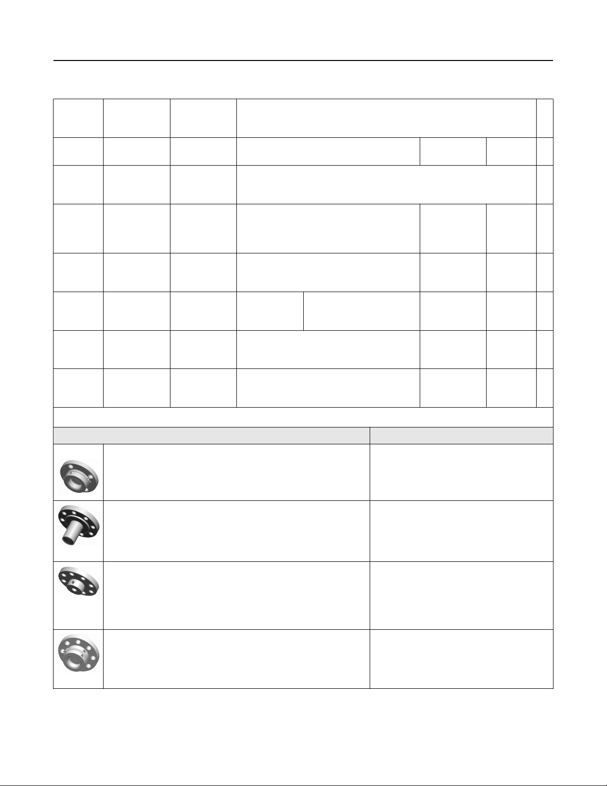
Table 3: Rosemount 3051SAL Scalable Level Transmitter Ordering Information (continued)
November 2018
V Silicone 705 for
vacuum
applications
(17)
Y
UltraTherm
805
(17)
Z
UltraTherm
805 for vacuum
applications
1.09 For use in vacuum applications below 14.7 psia (1 bar-a), refer to vapor
pressure curves in Rosemount DP Level Fill Fluid Specification Technical
Note.
™
1.20 N/A Up to 770 °F
( 410 °C)
1.20 For use in vacuum applications below 14.7 psia (1 bar-a), refer to vapor
pressure curves in Rosemount DP Level Fill Fluid Specification Technical
Note.
(18)
N/A ★
A SYLTHERM XLT 0.85 –157 to 293 °F (–105 to 145 °C) N/A -157 to
293 °F
(-105 to
145 °C)
H Inert
(Halocarbon)
1.85 –49 to 320 °F (–45 to 160 °C) N/A -49 to 320
°F (-45 to
160 °C)
(16)
N
Neobee® M-20 0.94 5 to 401 °F (–15
to 205 °C)
5 to 437 °F (–15 to 225 °C) N/A 5 to 437 °F
(-15 to 225
°C)
(10)(16)
G
Glycerin and
water
1.13 5 to 203 °F (–15 to 95 °C) N/A 5 to 437 °F
(-15 to 225
°C)
(10)(16)
P
Propylene
glycol and
water
1.02 5 to 203 °F (–15 to 95 °C) N/A 5 to 203 °F
(-15 to 95
°C)
★
★
★
★
★
★
★
Continue specifying a completed model number by choosing a remote seal type below:
Seal style Process connections
FF Flush Flanged Seal
2-in./DN 50/ 50A
3-in./DN 80/80A
4 in./DN 100/100A
EF Extended Flanged Seal 3-in./DN 80/80A
4-in./DN 100/100A
Remote Flanged (RF) Seal ½-in.
¾-in.
1-in./DN 25/25A
1½-in./DN 40/40A
PF Pancake Seal 2-in./DN 50/50A
3-in./DN 80/80A
28 Emerson.com/Rosemount
November 2018
Table 3: Rosemount 3051SAL Scalable Level Transmitter Ordering Information (continued)
FC Flush Flanged Seal - Ring Type Joint (RTJ) gasket surface 2-in.
3-in.
RC Remote Flanged Seal - Ring Type Joint (RTJ) gasket surface ½-in.
¾-in.
1 in.
1½-in.
RT Remote Threaded Seal ¼–18 NPT
½–14 NPT
¾–14 NPT
1–11.5 NPT
1¼–11.5 NPT
SC Hygienic Tri-Clamp Seal 1½-in.
2-in.
3-in.
SS Hygienic Tank Spud Seal 4-in.
Wireless options (requires option code X and wireless Plantweb housing)
Update rate
(4)
WA User configurable update rate ★
Operating frequency and protocol
3 2.4 GHz DSSS, IEC 62591 (WirelessHART) ★
Omni-directional wireless antenna
(4)
WK
WM
(4)
External antenna ★
Extended range, external antenna ★
WN High-gain, remote antenna
™
SmartPower
(19)(20)
1 Adapter for Black Power Module (I.S. Power Module sold separately) ★
Other options (include with selected model number)
HART Revision configuration (requires HART Protocol output code A)
HR7 Configured for HART Revision 7 ★
Product Data Sheet 29

November 2018
Table 3: Rosemount 3051SAL Scalable Level Transmitter Ordering Information (continued)
Extended product warranty
WR3 3-year limited warranty ★
WR5 5-year limited warranty ★
Plantweb control functionality
(20)(21)(22)
A01 FOUNDATION Fieldbus advanced control function block suite ★
Diagnostics suite
(20)(21)
D01
DA2
(23)
FOUNDATION Fieldbus diagnostics suite (Process Intelligence, Plugged Impulse Line diagnostic) ★
Advanced HART diagnostics suite (Process Intelligence, Loop Integrity, Plugged Impulse Line diagnostic, Process
Alerts, Service Alerts, Variable Log, Event Log)
Mounting bracket
B4 Bracket, all SST, 2-in. pipe panel ★
BE Bracket, 316 SST, B4-style with 316 SST bolting ★
Software configuration
(24)
C1 Custom software configuration (requires Configuration Data Sheet) ★
Gage pressure calibration
★
C3 Gage pressure calibration on Rosemount 3051SAL_ _A4 only ★
Alarm limit
(21)(24)
C4 NAMUR alarm and saturation levels, high alarm ★
C5 NAMUR alarm and saturation levels, low alarm ★
C6 Custom alarm and saturation signal levels, high alarm (requires C1 and Configuration Data Sheet) ★
C7 Custom alarm and saturation signal levels, low alarm (requires C1 and Configuration Data Sheet) ★
C8 Low alarm (standard Rosemount alarm and saturation levels) ★
Hardware adjustments
(24)(25)(26)
D1 Hardware adjustments (zero, span, alarm, security) ★
Flange adapter
D2 ½–14 NPT flange adapter ★
D9 RC½ SST flange adapter
Ground screw
(27)
D4 External ground screw assembly ★
Drain/vent valve
D5 Delete transmitter drain/vent valves (install plugs) ★
Conduit plug
(28)
DO 316 SST conduit plug ★
Product certifications
(29)
E1 ATEX Flameproof ★
I1 ATEX Intrinsic Safety ★
30 Emerson.com/Rosemount
 Loading...