

Rosemount 2051CF Series, 2051 Quick Start Manual

Quick Start Guide
00825-0100-4107, Rev DC
February 2019
Rosemount™ 2051 Pressure Transmitter
and Rosemount 2051CF Series
Flowmeter
with 4–20 mA HART® and 1–5Vdc Low
Power HART Protocol (Revision 5 and 7)

Safety messages
NOTICE
Read this manual before working with the product. For personal and system safety, and for optimum
product performance make sure you thoroughly understand the contents before installing, using, or
maintaining this product.
For technical assistance, contacts are listed below:
Customer Central
Technical support, quoting, and order-related questions. United States - 1-800-999-9307
(7:00 am to 7:00 pm CST) Asia Pacific- 65 777 8211Europe/Middle East/Africa - 49 (8153) 9390
North American Response Center
Equipment service needs.
1-800-654-7768 (24 hours—includes Canada)
Outside of these areas, contact your local Emerson™ representative.
CAUTION
The products described in this document are NOT designed for nuclear-qualified applications. Using
non-nuclear qualified products in applications that require nuclear-qualified hardware or products may
cause inaccurate readings.For information on Rosemount nuclear-qualified products, contact your
local Emerson Sales Representative.
WARNING
Explosions could result in death or serious injury.
Installation of this transmitter in an explosive environment must be in accordance with the appropriate
local, national, and international standards, codes, and practices. Review the approvals section of this
manual for any restrictions associated with a safe
• Before connecting a Field Communicator in an explosive atmosphere, ensure the instruments in
the loop are installed in accordance with intrinsically safe or non-incendive field wiring practices.
• In an explosion-proof/flameproof installation, do not remove the transmitter covers when power
is applied to the unit.
Process leaks may cause harm or result in death.
• Install and tighten process connectors before applying pressure.
• Do not attempt to loosen or remove flange bolts while the transmitter is in service.
Electrical shock can result in death or serious injury.
• Avoid contact with the leads and terminals. High voltage that may be present on leads can cause
electrical shock.
Quick Start Guide February 2019
2 Rosemount 2051 Pressure Transmitter Quick Start Guide

WARNING
• Before connecting a HART® communicator in an explosive atmosphere, ensure the instruments in
the loop are installed in accordance with intrinsically safe or non-incendive field wiring practices.
• In an Explosion-Proof/Flameproof installation, do not remove the transmitter covers when power
is applied to the unit.
Process leaks may cause harm or result in death.
• Install and tighten process connectors before applying pressure.
WARNING
Replacement equipment or spare parts not approved by Emerson for use as spare parts could reduce
the pressure retaining capabilities of the transmitter and may render the instrument dangerous.
• Use only bolts supplied or sold by Emerson as spare parts.
• Refer to page 208 for a complete list of spare parts.
Improper assembly of manifolds to traditional flange can damage sensor module.
• For safe assembly of manifold to traditional flange, bolts must break back plane of flange web
(i.e., bolt hole) but must not contact sensor module housing.
Contents
System readiness........................................... 5
Mount the transmitter................................... 7
Housing rotation..........................................14
Set the switches...........................................15
Connect the wiring and power up................ 16
Verify configuration..................................... 19
Trim the transmitter.................................... 23
Safety instrumented systems.......................26
Rosemount™ 2051 Product Certifications.....27
February 2019 Quick Start Guide
Quick Start Guide 3

Quick Start Guide February 2019
4 Rosemount 2051 Pressure Transmitter Quick Start Guide

1 System readiness
1.1 Confirm HART Revision capability
• If using HART based control or asset management systems, confirm the
HART capability of those systems prior to transmitter installation. Not all
systems are capable of communicating with HART Revision 7 protocol.
This transmitter can be configured for either HART Revision 5 or 7.
• For instructions on how to change the HART Revision of your transmitter,
see Switch HART Revision mode.
1.2 Confirm correct device driver
• Verify the correct device driver (DD/DTM™) is loaded on your systems to
ensure proper communications.
• Download the correct device driver at your host vendor download site,
EmersonProcess.com or Fieldbus.org.
1.2.1 Rosemount 2051 device revisions and drivers
Table 1-1 provides the information necessary to ensure you have the correct
device driver and documentation for your device.
Table 1-1: Rosemount 2051 Foundation Fieldbus Device Revisions and
Files
Device
Revision
(1)
Host Device driver
(DD)
(2)
Obtain at Device driver
(DTM)
Manual
Document
Number
2 All DD4: DD Rev1Fieldbus.org EmersonProce
ss.com
00809-0200-4
101,
Rev BA or
newer
All DD5: DD Rev1Fieldbus.org
Emerson AMS™ Device
Manager V
10.5 or
higher: DD
Rev 2
EmersonProce
ss.com
Emerson AMS Device
Manager V 8
to 10.5: DD
Rev 1
EmersonProce
ss.com
Emerson 375/475: DD
Rev 2
FieldCommun
icator.com
February 2019 Quick Start Guide
Quick Start Guide 5
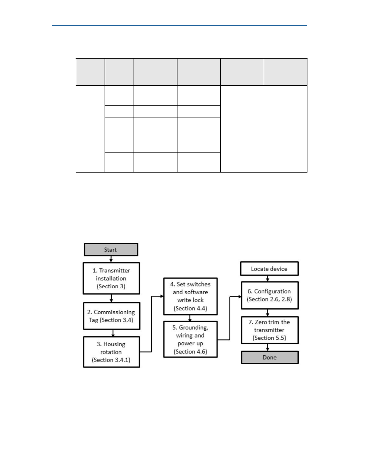
Table 1-1: Rosemount 2051 Foundation Fieldbus Device Revisions and
Files (continued)
Device
Revision
(1)
Host Device driver
(DD)
(2)
Obtain at Device driver
(DTM)
Manual
Document
Number
1 All DD4: DD Rev4Fieldbus.org EmersonProce
ss.com
00809-0200-4
101,
Rev AA
All DD5: NA N/A
Emerson AMS Device
Manager V
8or higher:
DD Rev 2
EmersonProce
ss.com
Emerson 375/475: DD
Rev 2
FieldCommun
icator.com
(1) Foundation Fieldbus device revision can be read using a Foundation Fieldbus
capable configuration tool.
(2) Device driver file names use device and DD revision. To access functionality, the
correct device driver must be installed on your control and asset management
hosts, and on your configuration tools.
Figure 1-1: Installation Flowchart
Quick Start Guide February 2019
6 Rosemount 2051 Pressure Transmitter Quick Start Guide
2 Mount the transmitter
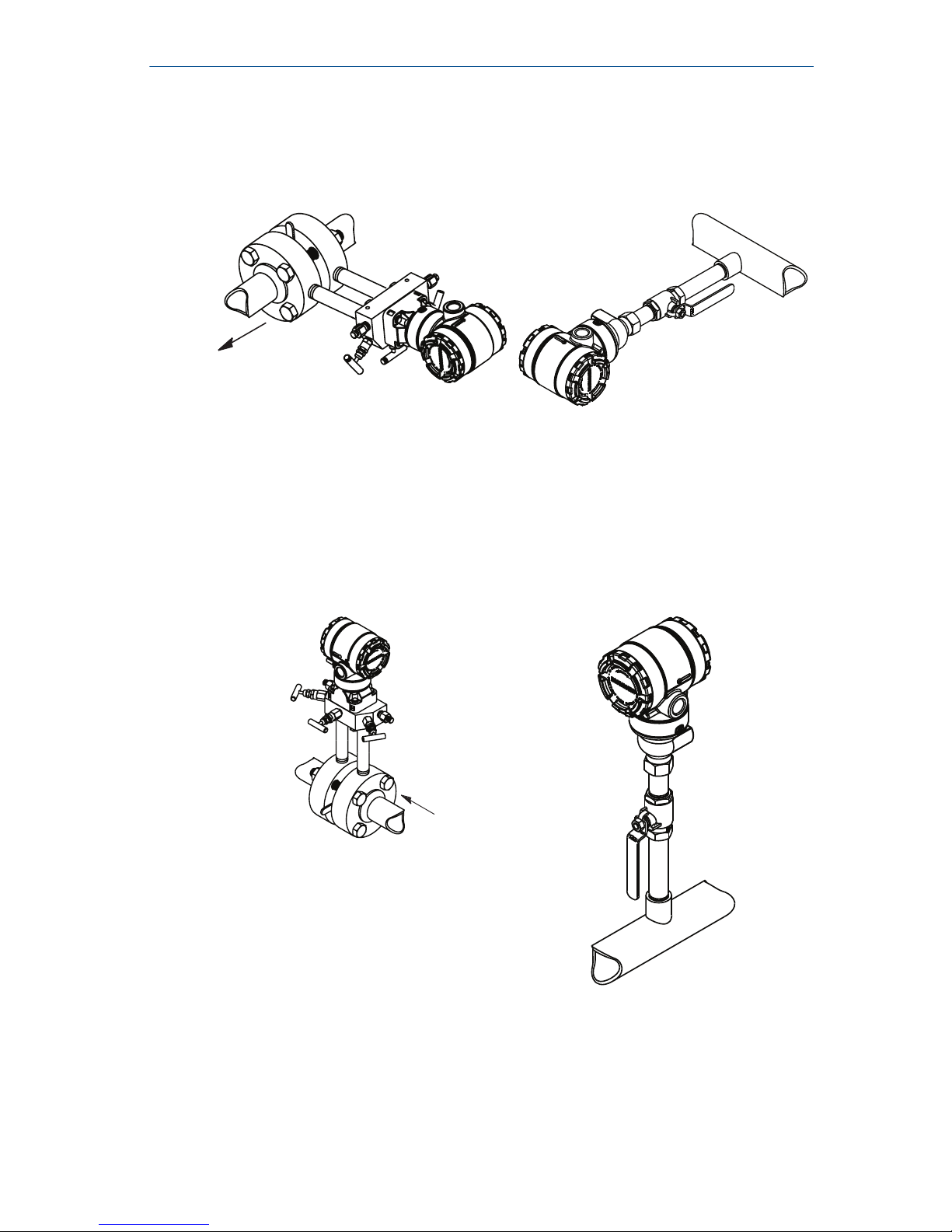
2.1 Liquid applications
Procedure
1. Place taps to the side of the line.
2. Mount beside or below the taps.
3. Mount the transmitter so the drain/vent valves are oriented upward.
2.2 Gas applications
Procedure
1. Place taps in the top or side of the line.
2. Mount beside or above the taps.
February 2019 Quick Start Guide
Quick Start Guide 7
2.3 Steam applications
Procedure
1. Place taps to the side of the line.
2. Mount beside or below the taps.
3. Fill impulse lines with water.
Example
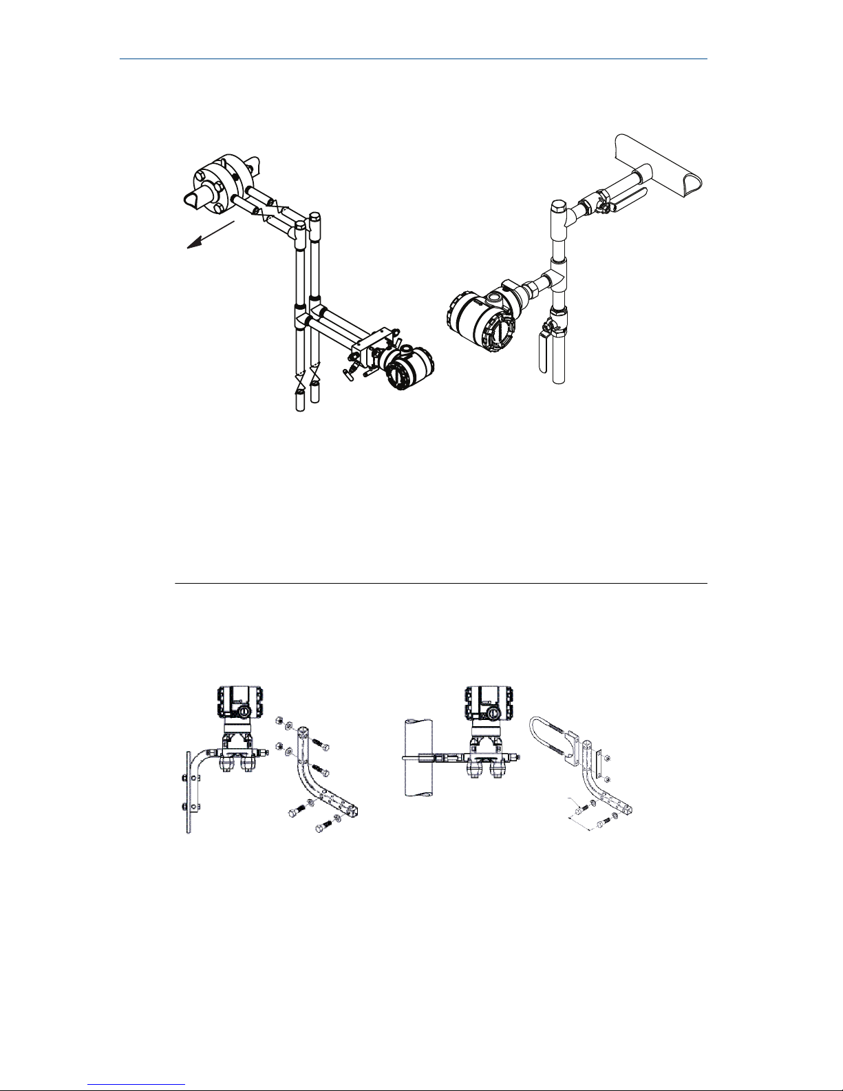
Figure 2-1: Panel and Pipe Mounting
Panel mount
(1)
Pipe mount
Coplanar flange
Traditional flange
Quick Start Guide February 2019
8 Rosemount 2051 Pressure Transmitter Quick Start Guide
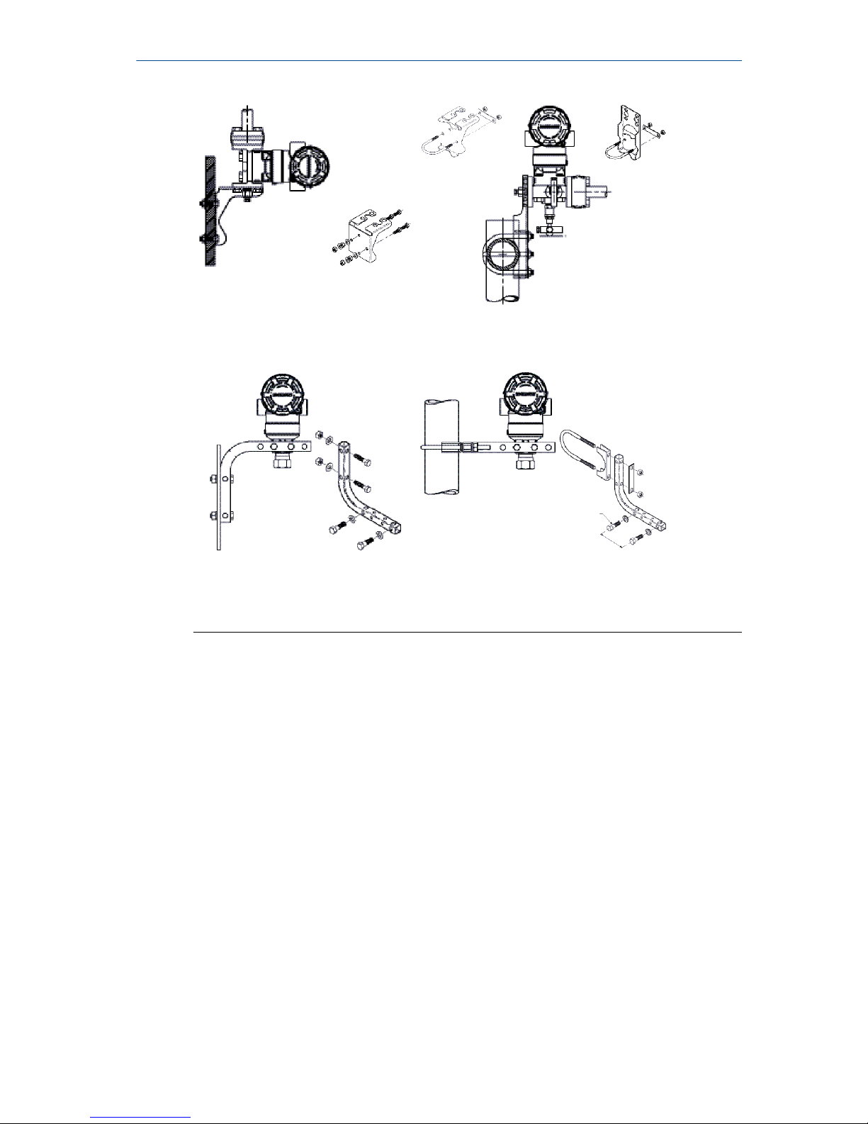
Rosemount 2051T
(1) × 1 panel bolts are customer supplied.
2.4
Bolting considerations
If the transmitter installation requires assembly of the process flanges,
manifolds, or flange adapters, follow the assembly guidelines to ensure a tight
seal for optimal performance characteristics of the transmitters. Use only
bolts supplied with the transmitter or sold by Emerson™ as spare parts. Figure
2-2 illustrates common transmitter assemblies with the bolt length required
for proper transmitter assembly.
February 2019 Quick Start Guide
Quick Start Guide 9
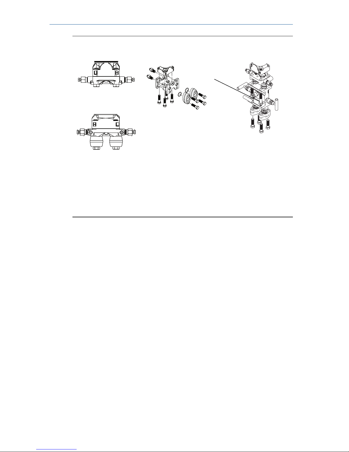
Figure 2-2: Common Transmitter Assemblies
A
4 × 1.75-in.
(44 mm)
D
4 × 1.75-in.
(44 mm)
4 × 2.25-in.
(57 mm)
C
4 × 1.75-in.
(44 mm)
4
× 1.50-in.
(38 mm)
B
4 × 2.88-in.
(73 mm)
A. Transmitter with coplanar flange
B. Transmitter with coplanar flange and optional flange adapters
C. Transmitter with traditional flange and optional flange adapters
D. Transmitter with coplanar flange and optional manifold and flange
adapters
Bolts are typically carbon steel or stainless steel. Confirm the material by
viewing the markings on the head of the bolt and referencing Table 2-1. If bolt
material is not shown in Table 2-1, contact a local Emerson Process
Management representative for more information.
Carbon steel bolts do not require lubrication and the stainless steel bolts are
coated with a lubricant to ease installation. However, no additional lubricant
should be applied when installing either type of bolt.
Use the following bolt installation procedure:
Procedure
1. Finger tighten the bolts.
2. Torque the bolts to the initial torque value using a crossing pattern.
See Table 2-1 for initial torque value.
3. Torque the bolts to the final torque value using the same crossing
pattern. See Table 2-1 for final torque value.
4. Verify the flange bolts are protruding through the sensor module bolt
holes before applying pressure.
Quick Start Guide February 2019
10 Rosemount 2051 Pressure Transmitter Quick Start Guide
Example
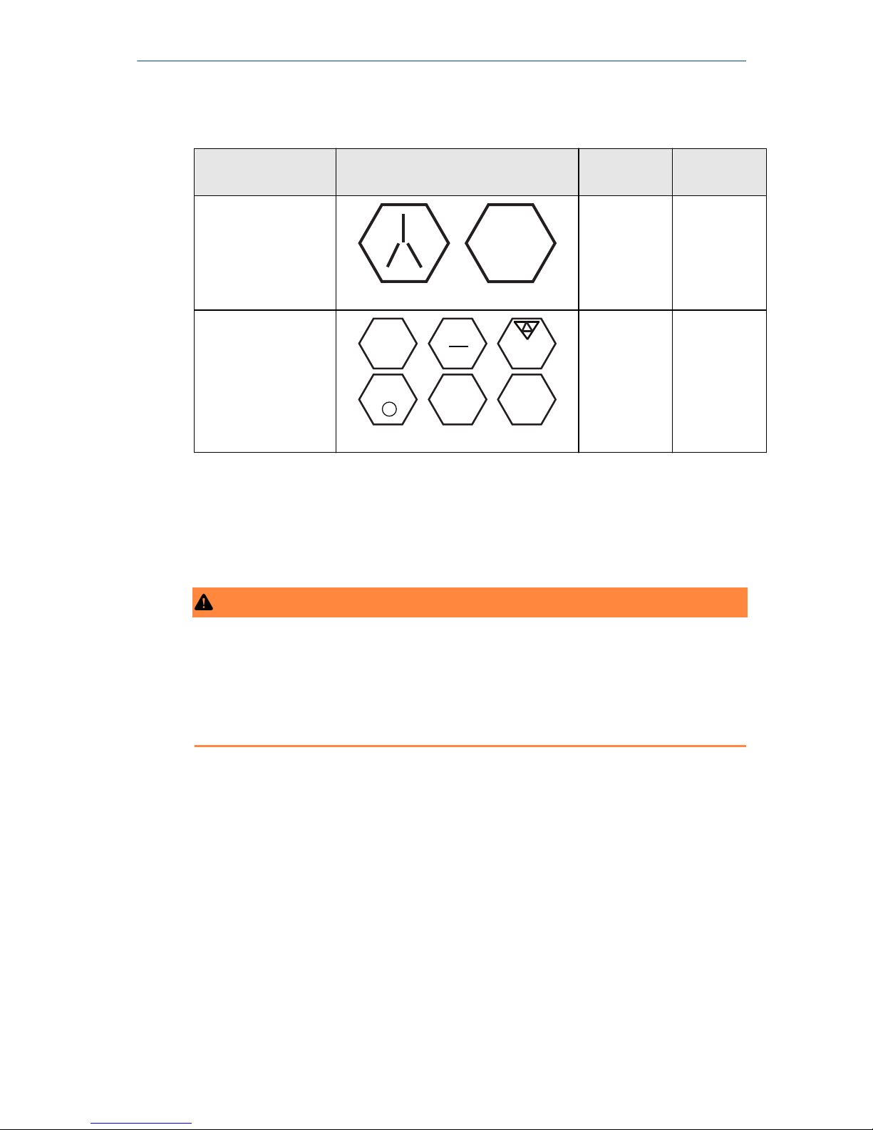
Table 2-1: Torque Values for the Flange and Flange Adapter Bolts
Bolt material Head markings Initial
torque
Final torque
Carbon Steel (CS)
B7M
300 in-lb 650 in-lb
Stainless Steel (SST)
316
316
316
SW
316
STM
316
R
B8M
150 in-lb 300 in-lb
2.5 O-rings
The two styles of Rosemount flange adapters (Rosemount 1151 and
Rosemount 3051/2051/2024/3095) each require a unique O-ring (see Figure
2-3). Use only the O-ring designed for the corresponding flange adapter.
WARNING
Failure to install proper flange adapter O-rings may cause process leaks, which
can result in death or serious injury. The two flange adapters are distinguished
by unique O-ring grooves. Only use the O-ring that is designed for its specific
flange adapter, as shown below. When compressed, PTFE O-rings tend to cold
flow, which aids in their sealing capabilities.
February 2019 Quick Start Guide
Quick Start Guide 11
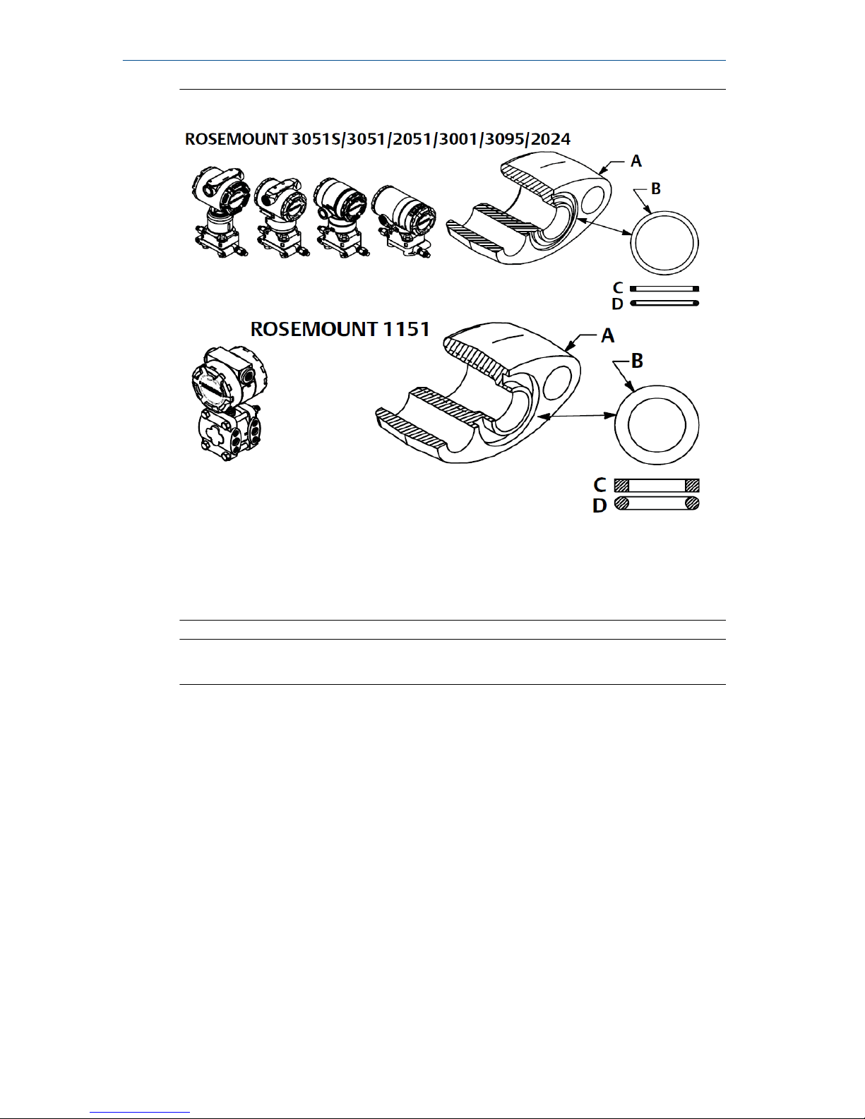
Figure 2-3: O-rings
A. Flange adapter
B. O-ring
C. PFTE based
D. Elastomer
Note
You should replace PTFE O-rings if you remove the flange adapter.
2.6
Environmental seal for housing
Thread sealing (PTFE) tape or paste on male threads of conduit is required to
provide a water/dust tight conduit seal and meets requirements of NEMA
®
Type 4X, IP66, and IP68. Consult factory if other Ingress Protection ratings are
required.
For M20 threads, install conduit plugs to full thread engagement or until
mechanical resistance is met.
2.7
In-line gage transmitter orientation
The low side pressure port (atmospheric reference) on the in-line gage
transmitter is located in the neck of the transmitter, behind the housing. The
vent path is 360° around the transmitter between the housing and sensor.
(See Figure 2-4.)
Quick Start Guide February 2019
12 Rosemount 2051 Pressure Transmitter Quick Start Guide

Keep the vent path free of any obstruction, including but not limited to paint,
dust, and lubrication by mounting the transmitter so fluids can drain away.
Figure 2-4: In-line Gage Low Side Pressure Port
A
A. Pressure port location
February 2019 Quick Start Guide
Quick Start Guide 13
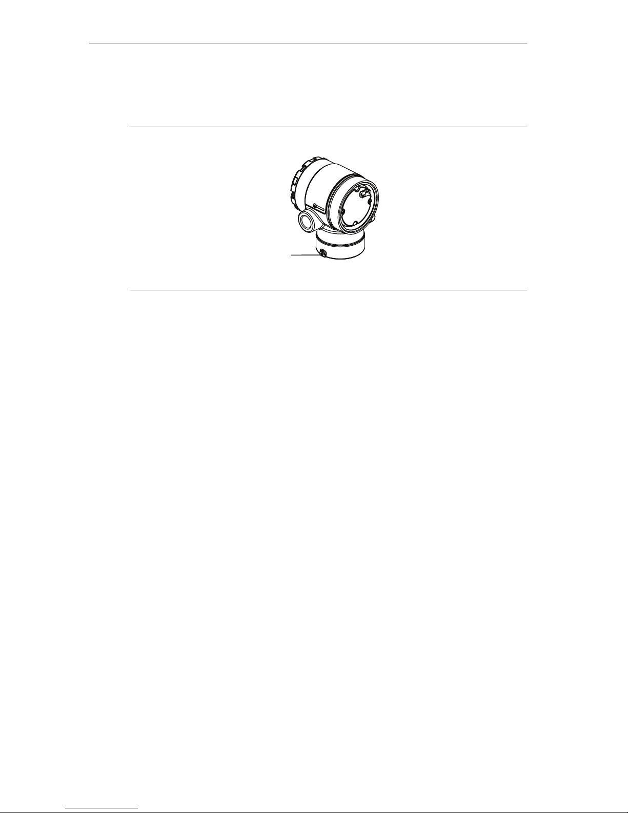
3 Housing rotation
To improve field access to wiring or to better view the optional LCD display:
Figure 3-1: Housing Rotation
A
A. Housing Rotation Set Screw (5/64-inch)
Procedure
1. Loosen the housing rotation set screw using a 5/64 -in. hex wrench.
2. Rotate the housing clockwise to the desired location.
3. If the desired location cannot be achieved due to thread limit, rotate
the housing counterclockwise to the desired location (up to 360° from
thread limit).
4. Re-tighten the housing rotation set screw to no more than 7 in-lbs
when desired location is reached.
Quick Start Guide February 2019
14 Rosemount 2051 Pressure Transmitter Quick Start Guide
 Loading...