

Page 1
Product Data Sheet
00813-0100-4101, Rev MA
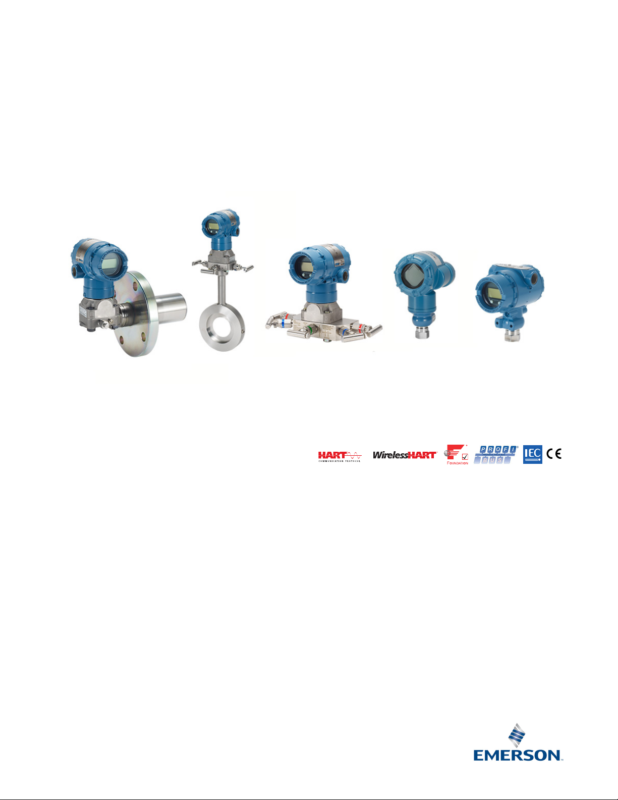
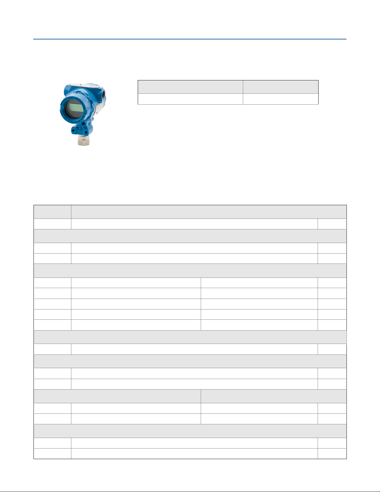
Rosemount™ 2051 Pressure Transmitter
February 2017
Rosemount Coplanar
™
platform enables integration of primary elements, manifolds, and remote seal
solutions
Best in Class performance with up to 0.05% high accuracy option
IEC 62591 (WirelessHART
Local Operator Interface (LOI) offers easy to use configuration capabilities at the transmitter
Protocols available include HART
®
) Protocol enables cost effective installations
®
4–20 mA, FOUNDATION™ Fieldbus, PROFIBUS® PA, HART 1–5 Vdc Low
Power
Selectable HART Revision prepares your plant for the latest HART capabilities while ensuring seamless
integration with today's systems
SIL2/3 safety certification to IEC 61508 is available with the full 4–20 mA HART offering to simplify
compliance
Page 2
Rosemount 2051
February 2017
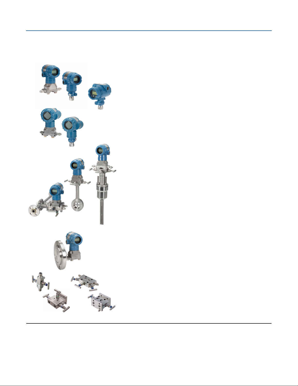
Rosemount 2051 Pressure Transmitter product offering
Foundation of reliable measurement
Differential, gage, and absolute pressure measurement
Select from an extensive offering of DP Flowmeters, liquid level, manifolds
and flanges
Available with variety of protocols and materials
Best-in-class capabilities extended to IEC 62591 (WirelessHART)
Cost effectively implement wireless on the industry's most proven platform
Optimize safety with the industry's only intrinsically safe power module
Eliminate wiring design and construction complexities to lower costs by
40–60 percent
Quickly deploy new pressure, level, and flow measurements in 70 percent
less time
Innovative, integrated DP Flowmeters
Fully assembled and leak tested for out-of-the-box installation
Reduce straight pipe requirements, lower permanent pressure loss, and
achieve accurate measurement in small line sizes
Up to two percent volumetric flow accuracy at 5:1 turndown
Proven, reliable, and innovative DP Level technologies
Connect to virtually any process with a comprehensive offering of process
connections, fill fluids, direct mount or capillary connections and materials.
Quantify and optimize total system performance with QZ option.
Optimize level measurement with cost efficient Tuned-System
™
Assemblies
Instrument manifolds — quality, convenient, and easy
Designed and engineered for optimal performance with Rosemount
transmitters
Save installation time and money with factory assembly
Offers a variety of styles, materials, and configurations
Contents
Rosemount 2051C Coplanar Pressure Transmitter . . . . . . . . . . 3
Rosemount 2051T In-line Pressure Transmitter . . . . . . . . . . . . 10
Rosemount 2051G In-Line Pressure Transmitter . . . . . . . . . . . 16
Rosemount 2051L Liquid Level Transmitter . . . . . . . . . . . . . . . 40
2
Specifications . . . . . . . . . . . . . . . . . . . . . . . . . . . . . . . . . . . . . . . . . 47
Product certifications . . . . . . . . . . . . . . . . . . . . . . . . . . . . . . . . . . 59
Dimensional drawings . . . . . . . . . . . . . . . . . . . . . . . . . . . . . . . . . . 69
Options . . . . . . . . . . . . . . . . . . . . . . . . . . . . . . . . . . . . . . . . . . . . . . 84
Emerson.com/Rosemount
Page 3
February 2017
Rosemount 2051
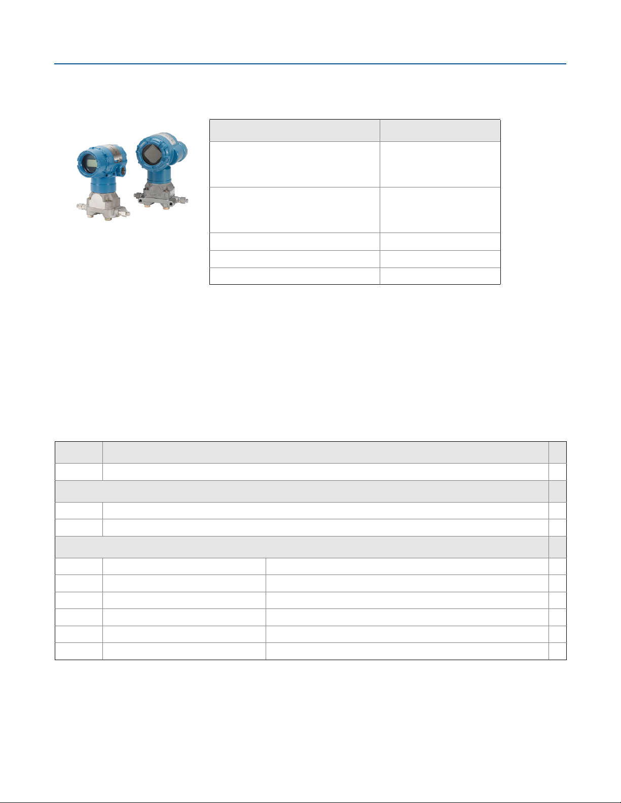
Rosemount 2051C Coplanar Pressure Transmitter
Configuration
4–20 mA HART
Rosemount 2051
Rosemount 2051 with Selectable HART
Lower Power
Rosemount 2051
Rosemount 2051 with Selectable HART
Rosemount 2051C Coplanar
Pressure Transmitter
Specification and selection of product materials, options, or components must be made by the purchaser of the equipment.
See page 56 for more information on material selection.
FOUNDATION Fieldbus F
PROFIBUS W
Wireless X
1. The 4-20 mA with Selectable HART device can be ordered with transmitter output option
code A plus any of the following options codes: M4, QT, DZ, CR, CS, CT, HR5, HR7.
Additional information
Specifications: page 47
Certifications: page 59
Dimensional Drawings: page 69
Transmitter output code
A
(1)
M
(1)
Table 1. Rosemount 2051C Coplanar Pressure Transmitters Ordering Information
The starred offerings (★) represent the most common options and should be selected for best delivery. The non-starred offerings are subject
to additional delivery lead time.
Model Transmitter type
2051C Coplanar Pressure Transmitter
Measurement type
D Differential ★
G Gage ★
Pressure range
Rosemount 2051CD Rosemount 2051CG
1 –25 to 25 inH2O (–62,2 to 62,2 mbar) –25 to 25 inH2O (–62,2 to 62,2 mbar) ★
2 –250 to 250 inH2O (–623 to 623 mbar) –250 to 250 inH2O (–623 to 623 mbar) ★
3 –1000 to 1000 inH2O (–2,5 to 2,5 bar) –393 to 1000 inH2O (–0,98 to 2,5 bar) ★
4 –300 to 300 psi (–20,7 to 20,7 bar) –14.2 to 300 psi (–0,98 to 20,7 bar) ★
5 –2000 to 2000 psi (–137,9 to 137,9 bar) –14.2 to 2000 psi (–0,98 to 137,9 bar) ★
Emerson.com/Rosemount
3
Page 4

Rosemount 2051
February 2017
Table 1. Rosemount 2051C Coplanar Pressure Transmitters Ordering Information
The starred offerings (★) represent the most common options and should be selected for best delivery. The non-starred offerings are subject
to additional delivery lead time.
Transmitter outp ut
(1)
A
4–20 mA with digital signal based on HART Protocol ★
F FOUNDATION Fieldbus Protocol ★
W PROFIBUS PA Protocol ★
X Wireless ★
M Low Power, 1–5 Vdc with digital signal based on HART Protocol
Materials of construction
Process flange type Flange material Drain/vent
2 Coplanar SST SST ★
(2)
3
5 Coplanar Plated CS SST ★
(2)
7
(2)
8
0 Alternate process connection ★
Coplanar Cast C-276 Alloy C-276 ★
Coplanar SST Alloy C-276 ★
Coplanar Plated CS Alloy C-276 ★
Isolating diaphragm
(2)
2
3
5
(2)
(3)(4)
316L SST ★
Alloy C-276 ★
Ta nt a l u m
O-ring
A Glass-filled PTFE ★
B Graphite-filled PTFE ★
Sensor fill fluid
1 Silicone ★
(4)
2
Inert ★
Housing material Conduit entry size
A Aluminum
B Aluminum M20 ⫻ 1.5 ★
J SST
(5)
K
(6)
P
SST M20 ⫻ 1.5 ★
Engineered polymer No conduit entries ★
D Aluminum G1/2
(5)
M
SST G1/2
1
/2–14 NPT ★
1
/2–14 NPT ★
4
Emerson.com/Rosemount
Page 5

February 2017
Rosemount 2051
Table 1. Rosemount 2051C Coplanar Pressure Transmitters Ordering Information
The starred offerings (★) represent the most common options and should be selected for best delivery. The non-starred offerings are subject
to additional delivery lead time.
Wireless options (requires wireless output code X and engineered polymer housing code P)
Wireless transmit rate, operating frequency and protocol
WA3 User configurable transmit rate, 2.4 GHz WirelessHART ★
Antenna and SmartPower
WP5 Internal antenna, compatible with green power module (I.S. power module sold separately) ★
™
Options (include with selected model number)
Extended product warranty
WR3 3-year limited warranty ★
WR5 5-year limited warranty
HART revision configuration
(7)
HR5
HR7
(8)
Configured for HART Revision 5 ★
Configured for HART Revision 7 ★
(18)
★
PlantWeb control functionality
A01 FOUNDATION Fieldbus advanced control function block suite ★
Alternate flange
H2 Traditional flange, 316 SST, SST drain/vent ★
(2)
H3
(2)
H7
HJ DIN compliant traditional flange, SST, 7/16-in. adapter/manifold bolting ★
FA Level flange, SST, 2-in., ANSI Class 150, vertical mount ★
FB Level flange, SST, 2-in., ANSI Class 300, vertical mount ★
FC Level flange, SST, 3-in., ANSI Class 150, vertical mount ★
FD Level flange, SST, 3-in., ANSI Class 300, vertical mount ★
FP DIN level flange, SST, DN 50, PN 40, vertical mount ★
FQ DIN level flange, SST, DN 80, PN 40, vertical mount ★
Alternate flange
(10)
HK
HL DIN compliant traditional flange, SST, 12 mm adapter/manifold bolting
Manifold assembly
(9)
Traditional flange, Cast C-276, Alloy C-276 drain/vent ★
Traditional flange, 316 SST, Alloy C-276 drain/vent ★
(9)
DIN compliant traditional flange, SST, 10 mm adapter/manifold bolting
(10)(11)
S5 Assemble to Rosemount 305 Integral Manifold ★
S6 Assemble to Rosemount 304 Manifold or connection system ★
Integral mount primary element
(12)
S4
Assemble to Rosemount 405A, 485, or 585 Annubar™ Primary Element or 1195 Integral Orifice Primary Element
(10)(11)
S3 Assemble to Rosemount 405C or 405P Compact Orifice Plate
Emerson.com/Rosemount
★
★
5
Page 6

Rosemount 2051
February 2017
Table 1. Rosemount 2051C Coplanar Pressure Transmitters Ordering Information
The starred offerings (★) represent the most common options and should be selected for best delivery. The non-starred offerings are subject
to additional delivery lead time.
Seal assemblies
(13)
S1
(14)
S2
(11)
Assemble to one Rosemount 1199 Diaphragm Seal ★
Assemble to two Rosemount 1199 Diaphragm Seals ★
Mounting brackets
B1 Traditional flange bracket for 2-in. pipe mounting, CS bolts ★
B2 Traditional flange bracket for panel mounting, CS bolts ★
B3 Traditional flange flat bracket for 2-in. pipe mounting, CS bolts ★
B4 Coplanar flange bracket for 2-in. pipe or panel mounting, all SST ★
B7 B1 bracket with Series 300 SST bolts ★
B8 B2 bracket with Series 300 SST bolts ★
B9 B3 bracket with Series 300 SST bolts ★
BA SST B1 bracket with Series 300 SST bolts ★
BC SST B3 bracket with Series 300 SST bolts ★
Product certifications
(5)
E1
(5)
E2
(5)
E3
(5)
E4
E5 USA Explosion-proof, Dust Ignition-proof
E6 Canada Explosion-proof, Dust Ignition-proof, Division 2
(5)
E7
EW India (CCOE) Flameproof Approval
(5)
I1
(5)
I2
(5)
I3
(5)(6)
I4
I5 USA Intrinsically Safe, Division 2
I6 Canada intrinsically Safe
(5)
I7
(15)
IA
(15)
IE
(15)
IF
(15)
IG
(5)
IW
(5)
K1
K2 INMETRO Flameproof and Intrinsic Safety ★
ATE X Flameproof ★
INMETRO Flameproof ★
China Flameproof ★
TIIS Flameproof
IECEx Flameproof
ATEX Intrinsic Safety
INMETRO Intrinsically Safe
China Intrinsic Safety
TIIS Intrinsic Safety
IECEx Intrinsic Safety
ATEX FISCO Intrinsic Safety
USA FISCO Intrinsically Safe ★
Canada FISCO Intrinsically Safe ★
IECEx FISCO Intrinsically Safe ★
India (CCOE) Intrinsically Safe ★
ATEX Flameproof, Intrinsic Safety, Type n, Dust ★
★
★
★
★
★
★
★
★
★
★
★
★
★
6
Emerson.com/Rosemount
Page 7

February 2017
Rosemount 2051
Table 1. Rosemount 2051C Coplanar Pressure Transmitters Ordering Information
The starred offerings (★) represent the most common options and should be selected for best delivery. The non-starred offerings are subject
to additional delivery lead time.
K5 USA Explosion-proof, Dust Ignition-proof, Intrinsically Safe, Division 2 ★
K6 Canada Explosion-proof, Dust Ignition-proof, Intrinsically Safe, Division 2 ★
(5)
K7
(5)
KA
KB USA and Canada Explosion-proof, Dust Ignition-proof, Intrinsically Safe, Division 2 ★
(5)
KC
(5)
KD
(5)
N1
(5)
N7
(5)
ND
EM Technical Regulations Customs Union (EAC) Flameproof ★
IM Technical Regulations Customs Union (EAC) Intrinsic Safety ★
KM Technical Regulations Customs Union (EAC) Flameproof and Intrinsic Safety ★
IECEx Flameproof, Intrinsic Safety, Type n and Dust ★
ATEX and Canada Flameproof, Intrinsically Safe, Division 2 ★
USA and ATEX Explosion-proof, Intrinsically Safe, Division 2 ★
USA, Canada, and ATEX Explosion-proof, Intrinsically Safe ★
ATEX Type n ★
IECEx Type n ★
ATE X Dust ★
Drinking water approval
(16)
DW
Shipboard approvals
NSF drinking water approval ★
(4)
SBS American Bureau of Shipping (ABS) type approval ★
SBV Bureau Veritas (BV) type approval ★
SDN Det Norske Veritas (DNV) type approval ★
SLL Lloyds Register (LR) type approval ★
Bolting materials
L4 Austenitic 316 SST bolts ★
L5 ASTM A 193, Grade B7M bolts ★
L6 Alloy K-500 bolts ★
L8 ASTM A 193 Class 2, Grade B8M bolts ★
Display and interface options
(17)
M4
LCD display with local operator interface ★
M5 LCD display ★
Hardware adjustments
(18)
D4
(19)
DZ
Flange adapters
DF
Conduit plug
Zero and span configuration buttons ★
Digital zero trim ★
(20)
1
/2–14 NPT flange adapters ★
(4)(21)
DO 316 SST conduit plug ★
Emerson.com/Rosemount
7
Page 8

Rosemount 2051
February 2017
Table 1. Rosemount 2051C Coplanar Pressure Transmitters Ordering Information
The starred offerings (★) represent the most common options and should be selected for best delivery. The non-starred offerings are subject
to additional delivery lead time.
RC 1/4 RC 1/2 process connection
D9 RC 1/4 flange with RC 1/2 flange adapter - SST
Ground screw
V5 External ground screw assembly ★
Performance
P8 High performance option ★
Transient protection
T1 Transient protection terminal block ★
Software configuration
(4)(23)
(24)
(4)(25)
(19)
(22)
C1
Alarm limit
(26)
C4
(26)
CN
Custom Software Configuration (Completed Rosemount 2051Configuration Data Sheet or Rosemount 3051
Configuration Data Sheet
(18)
for Wireless required with order)
NAMUR alarm and saturation levels, high alarm ★
NAMUR alarm and saturation levels, low alarm ★
CR Custom Alarm and saturation signal levels, high alarm (requires C1 and Configuration Data Sheet) ★
CS Custom Alarm and saturation signal levels, low alarm (requires C1 and Configuration Data Sheet) ★
CT Low Alarm (standard Rosemount alarm and saturation levels) ★
Pressure testing
P1 Hydrostatic testing with certificate
Cleaning process area
P2 Cleaning for special service
P3 Cleaning for < 1 PPM Chlorine/Flourine
Maximum static line pressure
P9 4500 psig (310 bar) static pressure limit (2051CD Ranges 2–5 only) ★
Calibration certification
Q4 Calibration certificate ★
QG Calibration certificate and GOST verification certificate ★
QP Calibration certification and tamper evident seal ★
★
Material traceability certification
Q8 Material traceability certification per EN 10204 3.1 ★
Quality certification for safety
QS Prior-use certificate of FMEDA data ★
8
(27)
Emerson.com/Rosemount
Page 9

February 2017
Rosemount 2051
Table 1. Rosemount 2051C Coplanar Pressure Transmitters Ordering Information
The starred offerings (★) represent the most common options and should be selected for best delivery. The non-starred offerings are subject
to additional delivery lead time.
QT Safety certified to IEC 61508 with certificate of FMEDA ★
Surface finish
Q16 Surface finish certification for sanitary remote seals ★
Toolkit total system performance reports
QZ Remote seal system performance calculation report ★
Conduit electrical connection
(4)
GE M12, 4-pin, male connector (eurofast®) ★
GM A size mini, 4-pin, male connector (minifast®) ★
NACE certificate
(28)
Q15 Certificate of compliance to NACE® MR0175/ISO 15156 for wetted materials ★
Q25 Certificate of compliance to NACE MR0103 for wetted materials ★
Typical model number: 2051C D 2 A 2 2 A 1 A B4 M5
1. HART Revision 5 is the default HART output. The Rosemount 2051 with Selectable HART can be factory or field configured to HART Revision 7.
To order HART Revision 7 factory configured, add option code HR7.
2. Materials of Construction comply with recommendations per NACE MR0175/ISO 15156 for sour oil field production environments. Environmental limits apply to
certain materials. Consult latest standard for details. Selected materials also conform to NACE MR0103 for sour refining environments. Order with Q15 or Q25 to
receive a NACE certificate.
3. Available in Ranges 2–5 only.
4. Not available with output code X.
5. Not available with low power output code M.
6. Only available with output code X.
7. Configures the HART output to HART Revision 5. The device can be field configured to HART Revision 7 if needed.
8. Configures the HART output to HART Revision 7. The device can be field configured to HART Revision 5 if needed.
9. Requires 0 code in Materials of Construction for alternate process connection.
10. Not valid with optional code P9 for 4500 psi static pressure.
11. “Assemble-to” items are specified separately and require a completed model number.
12. Process flange limited to coplanar (codes 2, 3, 5, 7, 8) or traditional (H2, H3, H7).
13. Not valid with optional code D9 for RC
14. Not valid with optional codes DF or D9 for adapters.
15. Only valid with F
16. Not available with Alloy C-276 isolator (3 code), tantalum isolator (5 code), all cast C-276 flanges, all plated CS flanges, all DIN flanges, all Level flanges, assemble-to
manifolds (S5 and S6 codes), assemble-to seals (S1 and S2 codes), assemble-to primary elements (S3 and S 4 codes), surface finish certification (Q16 code), and
remote seal system report (QZ code).
17. Not available with F
18. Only Available with HART 4–20 mA (output codes A and M).
19. Only available with HART 4–20 mA output(output codes A) and wireless output (code X).
20. Not valid with alternate process connection options S3, S4, S5, S6.
21. Transmitter is shipped with 316 SST conduit plug (uninstalled) in place of standard carbon steel conduit plug.
22. Not available with alternate process connection: DIN flanges and Level flanges.
23. The V5 option is not needed with the T1 o ption; external ground screw assembly is included with the T1 option.
24. Available with 4–20 mA HART output code A, wireless output code X, F
Ranges 1–4, SST and Alloy C 276 diaphragms and silicone fill fluid. High performance option includes 0.05% reference accuracy, and five year stability. See
Performance specifications for details.
25. The T1 option is not needed with FISCO Product Cer tifications; transient protection is included in the FISCO product certification codes IA and IE.
26. NAMUR-Compliant operation is pre-set at the factory and cannot be changed to standard operation in the field.
27. Only available with HART 4–20 mA output (code A).
28. NACE-Compliant wetted materials are identified by Footnote 2.
OUNDATION Fieldbus output code F.
OUNDATION Fieldbus output code F or wireless output code X.
1
/2 adapters.
OUNDATION Fieldbus output code F, Rosemount 2051C Ranges 2–5 or Rosemount 2051T
Emerson.com/Rosemount
9
Page 10
Rosemount 2051
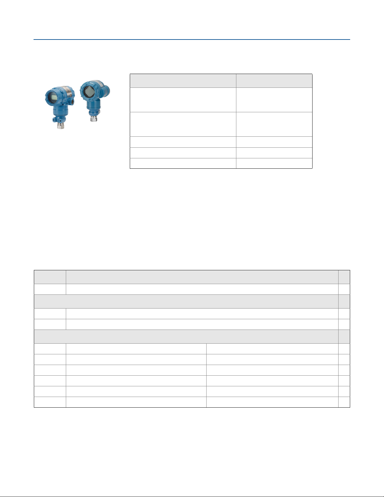
Rosemount 2051T In-line Pressure Transmitter
February 2017
Configuration
4–20 mA HART
Rosemount 2051
Rosemount 2051 with Selectable HART
Lower Power
Rosemount 2051
Rosemount 2051 with Selectable HART
Rosemount 2051T In-line
Wireless Pressure Transmitter
Specification and selection of product materials, options, or components must be made by the purchaser of the equipment.
See page 56 for more information on material selection.
FOUNDATION Fieldbus F
PROFIBUS W
Wireless X
1. The 4–20mA with Selectable HART device can be ordered with transmitter output option code
A plus any of the following options codes: M4, QT, DZ, CR, CS, CT, HR5, HR7.
Additional information
Specifications: page 47
Certifications: page 59
Dimensional Drawings: page 69
Transmitter output code
A
(1)
M
(1)
Table 2. Rosemount 2051T In-line Pressure Transmitter Ordering Information
★ The Standard offering represents the most common options. The starred options (★) should be selected for best delivery.
The Expanded offering is subject to additional delivery lead time.
Model Transmitter type
2051T In-line Pressure Transmitter ★
Pressure type
G Gage ★
(1)
A
Absolute ★
Pressure range
Rosemount 2051TG Rosemount 2051TA ★
1 -14.7 to 30 psi (–1,0 to 2,1 bar) 0 to 30 psi (0 to 2,1 bar) ★
2 –14.7 to 150 psi (–1,0 to 10,3 bar) 0 to 150 psi (0 to 10,3 bar) ★
3 –14.7 to 800 psi (–1,0 to 55 bar) 0 to 800 psi (0 to 55 bar) ★
4 –14.7 to 4000 psi (–1,0 to 276 bar) 0 to 4000 psi (0 to 276 bar) ★
5 –14.7 to 10000 psi (–1,0 to 689 bar) 0 to 10000 psi (0 to 689 bar) ★
10
Emerson.com/Rosemount
Page 11
February 2017
Rosemount 2051
Table 2. Rosemount 2051T In-line Pressure Transmitter Ordering Information
★ The Standard offering represents the most common options. The starred options (★) should be selected for best delivery.
The Expanded offering is subject to additional delivery lead time.
Transmitter outp ut
(2)
A
4–20 mA with Digital Signal Based on HART Protocol ★
F FOUNDATION Fieldbus Protocol ★
W PROFIBUS PA Protocol ★
X Wireless ★
M Low-Power, 1–5 Vdc with Digital Signal Based on HART Protocol
Process connection style
2B
2C
2F
(3)
(4)
1
/2–14 NPT female ★
G1/2 A DIN 16288 male ★
Coned and threaded, compatible with autoclave type F-250-C (Range 5 only)
Isolating diaphragm Process connection wetted parts material
(5)
2
(5)
3
316L SST 316L SST ★
Alloy C-276 Alloy C-276 ★
Sensor fill fluid
1 Silicone ★
(4)
2
Inert ★
Housing material Conduit entry size
A Aluminum
B Aluminum M20 x 1.5 ★
J SST
(6)
K
(7)
P
SST M20 x 1.5 ★
Engineered polymer No conduit entries ★
D Aluminum G1/2
(6)
M
SST G1/2
1
/2–14 NPT ★
1
/2–14 NPT ★
Wireless options (requires wireless output code X and engineered polymer housing code P)
Wireless transmit rate, operating frequency and protocol
WA3 User configurable transmit rate, 2.4 GHz WirelessHART ★
Antenna and SmartPower
WP5 Internal antenna, compatible with green power module (I.S. power module sold separately) ★
Options (include with selected model number)
Extended product warranty
WR3 3-year limited warranty ★
Emerson.com/Rosemount
11
Page 12

Rosemount 2051
February 2017
Table 2. Rosemount 2051T In-line Pressure Transmitter Ordering Information
★ The Standard offering represents the most common options. The starred options (★) should be selected for best delivery.
The Expanded offering is subject to additional delivery lead time.
WR5 5-year limited warranty ★
HART revision configuration
(8)
HR5
HR7
(9)
Configured for HART Revision 5 ★
Configured for HART Revision 7 ★
(18)
PlantWeb control functionality
A01 FOUNDATION Fieldbus advanced control function block suite ★
Manifold assemblies
(10)
S5 Assemble to Rosemount 306 Integral Manifold ★
Seal assemblies
(10)
S1
(10)
Assemble to one Rosemount 1199 Diaphragm Seal ★
Mounting bracket
B4 Bracket for 2-in. pipe or panel mounting, All SST ★
Product certifications
(6)
E1
(6)
E2
(6)
E3
(6)
E4
E5 USA Explosion-proof, Dust Ignition-proof ★
E6 Canada Explosion-proof, Dust Ignition-proof, Division 2 ★
(6)
E7
(6)
EW
(6)
I1
(6)
I2
(6)
I3
(6)(7)
I4
I5 USA Intrinsically Safe, Division 2 ★
I6 Canada Intrinsically Safe ★
(6)
I7
(13)
IA
(11)
IE
(11)
IF
(11)
IG
(6)
IW
(6)
K1
ATE X Flameproof ★
INMETRO Flameproof ★
China Flameproof ★
TIIS Flameproof ★
IECEx Flameproof ★
India (CCOE) Flameproof Approval ★
ATEX Intrinsic Safety ★
INMETRO Intrinsically Safe ★
China Intrinsic Safety ★
TIIS Intrinsic Safety ★
IECEx Intrinsic Safety ★
ATEX FISCO Intrinsic Safety ★
USA FISCO Intrinsically Safe ★
Canada FISCO Intrinsically Safe ★
IECEx FISCO Intrinsically Safe ★
India (CCOE) Intrinsic Safety Approval ★
ATEX Flameproof, Intrinsic Safety, Type n, Dust ★
12
Emerson.com/Rosemount
Page 13

February 2017
Rosemount 2051
Table 2. Rosemount 2051T In-line Pressure Transmitter Ordering Information
★ The Standard offering represents the most common options. The starred options (★) should be selected for best delivery.
The Expanded offering is subject to additional delivery lead time.
K5 USA Explosion-proof, Dust Ignition-proof, Intrinsically Safe, Division 2 ★
K6 Canada Explosion-proof, Dust Ignition-proof, Intrinsically Safe, Division 2 ★
(6)
K7
(6)
KA
KB USA and Canada Explosion-proof, Dust Ignition-proof, Intrinsically Safe, Division 2 ★
(6)
KC
(6)
KD
(6)
N1
(6)
N7
(6)
ND
EM Technical Regulations Customs Union (EAC) Flameproof ★
IM Technical Regulations Customs Union (EAC) Intrinsic Safety ★
KM Technical Regulations Customs Union (EAC) Flameproof and Intrinsic Safety ★
Drinking water approval
IECEx Flameproof, Intrinsic Safety, Type n, Dust ★
ATEX and Canada Flameproof, Intrinsically Safe, Division 2 ★
USA and ATEX Explosion-proof, Intrinsically Safe, Division 2 ★
USA, Canada, and ATEX Explosion-proof, Intrinsically Safe ★
ATEX Type n ★
IECEx Type n ★
ATE X Dust ★
(12)
DW NSF drinking water approval ★
Shipboard approvals
(4)
SBS American Bureau of Shipping (ABS) type approval ★
SBV Bureau Veritas (BV) type approval ★
SDN Det Norske Veritas (DNV) type approval ★
SLL Lloyds Register (LR) type approval ★
Display and interface options
(13)
M4
LCD display with local operator interface ★
M5 LCD display ★
Hardware adjustments
(14)
D4
(15)
DZ
Wireless SST sensor module
WSM Wireless SST sensor module ★
Conduit plug
DO 316 SST conduit plug ★
Ground screw
Zero and span configuration buttons ★
Digital zero trim ★
(7)
(4)(16)
(4)(17)
V5 External ground screw assembly ★
Performance
(18)
P8 High performance option ★
Emerson.com/Rosemount
13
Page 14
Rosemount 2051
February 2017
Table 2. Rosemount 2051T In-line Pressure Transmitter Ordering Information
★ The Standard offering represents the most common options. The starred options (★) should be selected for best delivery.
The Expanded offering is subject to additional delivery lead time.
Terminal b locks
T1 Transient protection terminal block ★
Software configuration
(4)(19)
(15)
C1
Alarm limits
(20)
C4
(21)
CN
Custom Software Configuration (Completed Rosemount 2051Configuration Data Sheet or Rosemount 3051
Configuration Data Sheet
(14)
for Wireless required with order)
Analog output levels compliant with NAMUR recommendation NE 43, alarm high ★
Analog output levels compliant with NAMUR recommendation NE 43, alarm low ★
CR Custom alarm and saturation signal levels, high alarm (requires C1 and Configuration Data Sheet) ★
CS Custom alarm and saturation signal levels, low alarm (requires C1 and Configuration Data Sheet) ★
CT Low alarm (standard Rosemount alarm and saturation levels) ★
Pressure testing
P1 Hydrostatic testing with certificate
Cleaning process area
(22)
P2 Cleaning for special service
P3 Cleaning for <1 PPM Chlorine/Fluorine
Calibration certification
Q4 Calibration certificate ★
QG Calibration certificate and GOST verification certificate ★
QP Calibration certificate and tamper evident seal ★
★
Material traceability certification
Q8 Material traceability certification per EN 10204 3.1 ★
Quality certification for safety
(21)
QS Prior-use certificate of FMEDA data ★
QT Safety certified to IEC 61508 with certificate of FMEDA ★
Surface finish
Q16 Surface finish certification for sanitary remote seals ★
Toolkit total system performance reports
QZ Remote seal system performance calculation report ★
Conduit electrical connector
GE M12, 4-pin, male connector (eurofast) ★
GM A size mini, 4-pin, male connector (minifast) ★
14
(4)
Emerson.com/Rosemount
Page 15

February 2017
Rosemount 2051
Table 2. Rosemount 2051T In-line Pressure Transmitter Ordering Information
★ The Standard offering represents the most common options. The starred options (★) should be selected for best delivery.
The Expanded offering is subject to additional delivery lead time.
NACE certificate
(23)
Q15 Certificate of compliance to NACE MR0175/ISO 15156 for wetted materials ★
Q25 Certificate of compliance to NACE MR0103 for wetted materials ★
Typical model number: 2051T G 3 A 2B 2 1 A B4 M5
1. Wireless output (code X) only available in absolute measurement type (code A) in range 1–5 with 1/2–14 NPT process connection (code 2B), and housing (code P).
2. HART Revision 5 is the default HART output. The Rosemount 2051 with Selectable HART can be factory or field configured to HART Revision 7. To order HART
Revision 7 factory configured, add option code HR7.
3. Wireless output (code X) only available in G
fluid (code 1), and housing (code P).
4. Not available with output code X.
5. Materials of Construction comply with recommendations per NACE MR0175/ISO 15156 for sour oil field production environments. Environmental limits apply to
certain materials. Consult latest standard for details. Selected materials also conform to NACE MR0103 for sour refining environments. Order with Q15 or Q25 to
receive a NACE certificate.
6. Not available with low power output code M.
7. Only available with output code X.
8. Configures the HART output to HART Revision 5. The device can be field configured to HART Revision 7 if needed.
9. Configures the HART output to HART Revision 7. The device can be field configured to HART Revision 5 if needed.
10. “Assemble-to” items are specified separately and require a completed model number.
11. Only valid with F
12. Not available with coned and threaded connection (2F code), assemble-to manifold (S5 code), assemble-to seal (S1 code), surface finish certification (Q16 code),
remote seal system report (QZ code).
13. Not available with F
14. Only Available with HART (output codes A and M).
15. Only available with HART 4–20 mA output (code A) and wireless output (code X).
16. Transmitter is shipped with 316 SST conduit plug (uninstalled) in place of standard carbon steel conduit plug.
17. The V5 option is not needed with the T1 o ption; external ground screw assembly is included with the T1 option.
18. Available with 4–20 mA HART output code A, wireless output code X, F
Ranges 1–4, SST and Alloy C 276 diaphragms and silicone fill fluid. High performance option includes 0.05% reference accuracy, and five year stability. See
Performance specifications for details.
19. The T1 option is not needed with FISCO Product Cer tifications; transient protection is included in the FISCO product certification codes IA and IE.
20. NAMUR-Compliant operation is pre-set at the factory and cannot be changed to standard operation in the field.
21. Only available with HART 4–20 mA output (code A).
22. Not valid with alternate process connection S5.
23. NACE Compliant wetted materials are identified by Footnote 5.
OUNDATION Fieldbus output code F.
OUNDATION Fieldbus output code F or wireless output code X.
1
/2 A DIN 16288 Male process connection (code 2C) with range 1–4, 316 SST isolating diaphragm (code 2), silicone fill
OUNDATION Fieldbus output code F, Rosemount 2051C Ranges 2–5 or Rosemount 2051T
Emerson.com/Rosemount
15
Page 16
Rosemount 2051
Rosemount 2051G In-Line
Pressure Transmitter
Rosemount 2051G In-Line Pressure Transmitter
February 2017
Configuration
4–20 mA HART A
Additional Information
Specifications: page 47
Certifications: page 59
Dimensional Drawings: page 69
Transmitter output code
Table 3. Rosemount 2051G In-Line Pressure Transmitter Ordering Information
★ The Standard offering represents the most common options. The starred options (★) should be selected for best delivery.
The Expanded offering is subject to additional delivery lead time.
Model Transmitter t ype
2051G In-line pressure transmitter
Pressure type
P Gage ★
A Absolute ★
Pressure range
Rosemount 2051GP Rosemount 2051GA ★
1 -14.7 to 30 psi (-1.0 to 2.1 bar) 0 to 30 psi (0 to 2.1 bar) ★
2 -14.7 to 150 psi (-1.0 to 10.3 bar) 0 to 150 psi (0 to 10.3 bar) ★
3 -14.7 to 800 psi (-1.0 to 55 bar) 0 to 800 psi (0 to 55 bar) ★
4 -14.7 to 4000 psi (-1.0 to 276 bar) 0 to 4000 psi (0 to 276 bar) ★
Transmitter output
A 4–20 mA with Digital Signal Based on HART Protocol ★
Process connection style
2B
2C G1/2 DIN 16288 male ★
Isolating diaphragm
2 316L SST 316L SST ★
3 Alloy C-276 Alloy C-276 ★
1
/2–14 NPT female ★
(1)
Process connection wetted parts material
Sensor fill fluid
1 Silicone ★
2 Inert ★
16
Emerson.com/Rosemount
Page 17

February 2017
Rosemount 2051
Table 3. Rosemount 2051G In-Line Pressure Transmitter Ordering Information
★ The Standard offering represents the most common options. The starred options (★) should be selected for best delivery.
The Expanded offering is subject to additional delivery lead time.
Housing material Conduit entry size
A Aluminum ½–14 NPT ★
B Aluminum M20 × 1.5 ★
D Aluminum G 1/2 ★
Options (Include with selected model number)
Integral manifold assembly
S5 Assemble to Rosemount 306 Integral Manifold ★
Seal assemblies
(2)
(2)
S1 Assemble to one Rosemount 1199 Diaphragm Seal
Mounting bracket
B4 Bracket for 2-in. pipe or panel mounting, All SST ★
BE 316 SST B4 Bracket with 316 SST Bolts ★
Product certifications
E1 ATEX Fla mep roof
E2 INMETRO Flameproof
E3 China Flameproof
E5 USA Explosion-proof, Dust Ignition-proof
E6 Canada Explosion-proof, Dust Ignition-proof, Division 2
E7 IECEx Flameproof
EM Technical Regulations Customs Union (EAC) Flameproof
EP Republic of Korea Flameproof
EW India (CCOE) Flameproof
(3)
(4)
★
I1 ATEX Intrinsic Safety
I2 INMETRO Intrinsic Safety
I3 China Intrinsic Safety
I5 USA Intrinsic Safety, Nonincendive
I6 Canada Intrinsic Safety
I7 IECEx Intrinsic Safety
IM Technical Regulations Customs Union (EAC) Intrinsic Safety
IP Republic of Korea Intrinsic Safety
IW India (CCOE) Intrinsic Safety
K1 ATEX Flame-proof, Intrinsic Safety, Type n, Dust (combination of E1, I1 and N1)
K2 INMETRO Flameproof, Intrinsic Safety
K3 China Flameproof, Intrinsic Safety
Emerson.com/Rosemount
17
Page 18

Rosemount 2051
Table 3. Rosemount 2051G In-Line Pressure Transmitter Ordering Information
★ The Standard offering represents the most common options. The starred options (★) should be selected for best delivery.
The Expanded offering is subject to additional delivery lead time.
K5 USA Explosion-proof, Dust Ignition-proof, Intrinsic Safety, and Nonincendive
K6 Canada Explosion-proof, Dust Ignition-proof, Intrinsic Safety, and Division 2
K7 IECEx Flameproof, Dust Ignition-proof, Intrinsic Safety, and Type n (combo of I7, E7, N7 and NK)
KA Canada and ATEX Explosion proof, Dust Ignition-proof, Intrinsically Safety, division
KB
KD USA, Canada and ATEX Explosion proof, Intrinsically Safety (combination of K5, K6 I1 and E1)
KM Technical Regulations Customs Union (EAC) Flame-proof, Intrinsic Safety
KP Republic of Korea Flame-proof, Intrinsic Safety
N1 ATEX Type n
N3 China Type n
N7 IECEx Type n
ND ATEX Dust
NK IECEx Dust
Drinking water approval
USA and Canada Explosion-proof, Dust Ignition-proof, Intrinsic Safety,
and Division 2 (combo of K5 and K6)
(5)
February 2017
DW NSF drinking water approval
Pressure testing
P1 Hydrostatic testing with certificate
Cleaning process area
(6)
P2 Cleaning for special service
P3 Cleaning for <1PPM Chlorine/Flourine
Calibration certification
Q4 Calibration certificate ★
QG Calibration certificate and GOST verification certificate ★
QP Calibration certificate and tamper evident seal ★
Material traceability certification
Q8
Material traceability certification per EN 10204 3.1
Quality certification for safety
QT Safety certified to IEC 61508 with certificate of FMEDA ★
QS Prior-use certificate of FMEDA data ★
★
★
★
★
★
Configuration buttons
D4 Analog zero and span ★
DZ Digital zero trim ★
18
Emerson.com/Rosemount
Page 19

February 2017
Rosemount 2051
Table 3. Rosemount 2051G In-Line Pressure Transmitter Ordering Information
★ The Standard offering represents the most common options. The starred options (★) should be selected for best delivery.
The Expanded offering is subject to additional delivery lead time.
Conduit plug
DO 316 SST conduit plug ★
(7)
Ground screw
V5 External ground screw assembly ★
Performance
P8 High performance option ★
Display and interface options
M4 LCD display and Local Operator Interface ★
M5 LCD display ★
(8)
(9)
(10)
Transient terminal block
T1 Transient protection terminal block ★
Software configuration
C1 Custom Software Configuration (requires Configuration Data Sheet) ★
Alarm levels
C4 Analog output levels compliant with NAMUR recommendation NE 43, high alarm ★
CN Analog output levels compliant with NAMUR recommendation NE 43, low alarm ★
CR Custom alarm and saturation signal levels, high alarm (requires C1 and Configuration Data Sheet) ★
CS Custom alarm and saturation signal levels, low alarm (requires C1 and Configuration Data Sheet) ★
CT Low alarm (standard Rosemount alarm and saturation levels) ★
Extended product warranty
WR3 3-year warranty
WR5 5-year warranty
HART revision configuration
(11)
HR5
HR7
(12)
Configured for HART Revision 5 ★
Configured for HART Revision 7 ★
Surface finish
Q16 Surface finish certification for sanitary remote seals ★
Toolkit total system performance reports
QZ
Remote seals system performance calculation report ★
Emerson.com/Rosemount
19
Page 20

Rosemount 2051
Table 3. Rosemount 2051G In-Line Pressure Transmitter Ordering Information
★ The Standard offering represents the most common options. The starred options (★) should be selected for best delivery.
The Expanded offering is subject to additional delivery lead time.
Conduit electrical connection
February 2017
GE
GM
M12, 4-pin, male connector (eurofast
A size mini, 4-pin, male connector (minifast
NACE certificate
Q15
Q25
Certificate of compliance to NACE
Certificate of compliance to NACE MR0103 for wetted materials ★
(13)
(R)
) ★
(R)
) ★
(R)
MR0175/ISO 15156 for wetted materials ★
Stainless steel tagging
Y2
316SST Nameplates, Labels, Tags, and Fasteners
Typical model number: 2051G P 5 F 2A 2 1 A HR5 B4
1. Materials of Construction comply with recommendations per NACE MR0175/ISO 15156 for sour oil field production environments. Environmental limits apply to
certain materials. Consult latest standard for details. Selected materials also conform to NACE MR0103 for sour refining environments.
2. “Assemble-to” items are specified separately and require a completed model number.
3. Panel mounting bolts are not supplied.
4. Consult an Emerson Representative for availability of Product Certifications.
5. Not available with coned and threaded connection (2F code), assemble-to manifold (S5 code), assemble-to seal (S1 code), surface finish certification (Q16 code),
remote seal system report (QZ code).
6. Not valid with alternate process connection S5.
7. Transmitter is shipped with 316 SST conduit plug (uninstalled) in place of standard carbon steel conduit plug.
8. The V5 option is not needed with the T1 option; external ground screw assembly is included with the T1 option.
9. High performance option includes 0.15% reference accuracy, and seven years stability. See Performance specifications for details.
10. Select Configuration Buttons (option code D4 or DZ) if local configuration buttons are required.
11. Configures the HART output to HART Revision 5. The device can be field configured to HART Revision 7 if needed.
12. Configures the HART output to HART Revision 7. The device can be field configured to HART Revision 5 if needed.
13. NACE Compliant wetted materials are identified by Footnote 1.
20
Emerson.com/Rosemount
Page 21
February 2017
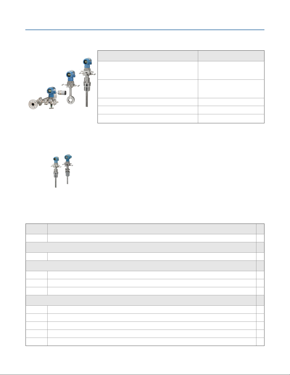
Rosemount 2051CF Flowmeters
Rosemount 2051
Configuration
4–20 mA HART
Rosemount 2051
Rosemount 2051 with Selectable HART
Lower Power
Rosemount 2051
Rosemount 2051 with Selectable HART
FOUNDATION Fieldbus F
PROFIBUS W
Wireless X
1. The 4–20 mA with Selectable HART device can be ordered with transmitter output option code A plus any of the
following options codes: M4, QT, DZ, CR, CS, CT, HR5, HR7.
Rosemount 2051CFA Annubar Flowmeter
Additional information
Specifications: page 47
Certifications: page 59
Dimensional Drawings: page 69
Transmitter output code
A
(1)
M
(1)
Specification and selection of product materials, options, or components must be made by the purchaser of the equipment.
See page 56 for more information on material selection.
Table 4. Rosemount 2051CFA Annubar Flowmeter Ordering Information
★ The Standard offering represents the most common options. The starred options (★) should be selected for best delivery.
The Expanded offering is subject to additional delivery lead time.
Model Product description
2051CFA Annubar Flowmeter
Measurement type
D Differential pressure ★
Fluid type
L Liquid ★
G Gas ★
S Steam ★
Line size
020 2-in. (50 mm) ★
025 21/2-in. (63,5 mm) ★
030 3-in. (80 mm) ★
035 31/2-in. (89 mm) ★
040 4-in. (100 mm) ★
Emerson.com/Rosemount
21
Page 22

Rosemount 2051
February 2017
Table 4. Rosemount 2051CFA Annubar Flowmeter Ordering Information
★ The Standard offering represents the most common options. The starred options (★) should be selected for best delivery.
The Expanded offering is subject to additional delivery lead time.
050 5-in. (125 mm) ★
060 6-in. (150 mm) ★
070 7-in. (175 mm) ★
080 8-in. (200 mm) ★
100 10-in. (250 mm) ★
120 12-in. (300 mm) ★
Pipe I.D. range
C Range C from the pipe I.D. table ★
D Range D from the pipe I.D. table ★
A Range A from the pipe I.D. table
B Range B from the pipe I.D. table
E Range E from the pipe I.D. table
Z Non-standard pipe I.D. range or line sizes greater than 12-in.
(1)
Pipe material/mounting assembly material
C Carbon steel (A105) ★
S 316 stainless steel ★
(2)
0
G Chrome-Moly Grade F-11
N Chrome-Moly Grade F-22
J Chrome-Moly Grade F-91
No mounting (customer supplied)
Piping orientation
H Horizontal piping ★
D Vertical piping with downwards flow ★
U Vertical piping with upwards flow ★
Annubar type
P Pak-Lok ★
F Flanged with opposite side support ★
Sensor material
S 316 stainless steel ★
Sensor size
1 Sensor size 1 — line sizes 2-in. (50 mm) to 8-in. (200 mm) ★
2 Sensor size 2 — line sizes 6-in. (150 mm) to 96-in. (2400 mm) ★
3 Sensor size 3 — line sizes greater than 12-in. (300 mm) ★
Mounting type
T1 Compression or threaded connection ★
22
Emerson.com/Rosemount
Page 23

February 2017
Rosemount 2051
Table 4. Rosemount 2051CFA Annubar Flowmeter Ordering Information
★ The Standard offering represents the most common options. The starred options (★) should be selected for best delivery.
The Expanded offering is subject to additional delivery lead time.
A1 Class 150 RF ANSI ★
A3 Class 300 RF ANSI ★
A6 Class 600 RF ANSI ★
D1 DN PN16 flange ★
D3 DN PN40 flange ★
D6 DN PN100 flange ★
R1 Class 150 RTJ flange
R3 Class 300 RTJ flange
R6 Class 600 RTJ flange
Opposite side support or packing gland
0 No opposite side support or packing gland (required for Pak-Lok and Flange-Lok models) ★
Opposite side support (required for flanged models)
C NPT threaded opposite support assembly — extended tip ★
D Welded opposite support assembly — extended tip ★
Isolation valve for Flo-Tap models
(2)
0
Not applicable or customer supplied ★
Temperature measurement
T Integral RTD – not available with flanged model greater than Class 600 ★
0 No temperature sensor ★
R Remote thermowell and RTD
Transmitter connection platform
3 Direct mount, Integral 3-valve manifold — not available with flanged model greater than Class 600 ★
5 Direct mount, 5-valve manifold — not available with flanged model greater than Class 600 ★
7 Remote mount NPT connections (1/2-in. FNPT) ★
8 Remote mount SW connections (1/2-in.)
Differential pressure range
1 0 to 25 in H2O (0 to 62,3 mbar) ★
2 0 to 250 in H2O (0 to 623 mbar) ★
3 0 to 1000 in H2O (0 to 2,5 bar) ★
Transmitter outp ut
(3)
A
F FOUNDATION Fieldbus Protocol ★
W PROFIBUS PA Protocol ★
X Wireless ★
4–20 mA with digital signal based on HART Protocol ★
Emerson.com/Rosemount
23
Page 24

Rosemount 2051
February 2017
Table 4. Rosemount 2051CFA Annubar Flowmeter Ordering Information
★ The Standard offering represents the most common options. The starred options (★) should be selected for best delivery.
The Expanded offering is subject to additional delivery lead time.
M Low-Power, 1–5 Vdc with digital signal based on HART Protocol
Transmitter housing material Conduit entry size
A Aluminum
B Aluminum M20 x 1.5 ★
J SST
(4)
K
(5)
P
SST M20 x 1.5 ★
Engineered polymer No conduit entries ★
D Aluminum G1/2
(4)
M
SST G1/2
1
/2–14 NPT ★
1
/2–14 NPT ★
Transmitter per formance class
1 2.0% flow rate accuracy, 5:1 flow turndown, 2-year stability ★
Wireless options (requires wireless output code X and engineered polymer housing code P)
Wireless transmit rate, operating frequency and protocol
WA3 User configurable transmit rate, 2.4 GHz WirelessHART ★
Antenna and SmartPower
WP5 Internal antenna, compatible with green power module (I.S. power module sold separately) ★
Options (include with selected model number)
Extended product warranty
WR3 3-year limited warranty ★
WR5 5-year limited warranty
Special cleaning
P2 Cleaning for special services
PA Cleaning per ASTM G93 Level D (Section 11.4)
Material testing
V1 Dye penetrant exam
Material examination
V2 Radiographic examination
Special inspection
(4)
(4)
(4)
(4)
★
QC1 Visual and dimensional inspection with certificate ★
QC7 Inspection and performance certificate ★
Surface finish
(4)
RL Surface finish for low pipe Reynolds number in gas and steam ★
24
Emerson.com/Rosemount
Page 25

February 2017
Rosemount 2051
Table 4. Rosemount 2051CFA Annubar Flowmeter Ordering Information
★ The Standard offering represents the most common options. The starred options (★) should be selected for best delivery.
The Expanded offering is subject to additional delivery lead time.
RH Surface finish for high pipe Reynolds number in liquid ★
Material traceability certification
Q8 Material traceability certification per EN 10474:2004 3.1 ★
Code conformance
(4)
J2 ANSI/ASME B31.1
J3 ANSI/ASME B31.3
Materials conformance
(4)(6)
J5 NACE MR-0175/ISO 15156
Country certification
(4)
J6 European Pressure Directive (PED) ★
J1 Canadian registration
Instrument connections for remote mount options
(4)(6)
(4)
G2 Needle valves, stainless steel ★
G6 OS&Y gate valve, stainless steel ★
G1 Needle valves, carbon steel
G3 Needle valves, Alloy C-276
G5 OS&Y gate valve, carbon steel
G7 OS&Y gate valve, Alloy C-276
Special shipment
(4)
Y1 Mounting hardware shipped separately ★
Product certifications
(4)
E1
(4)
E2
(4)
E3
E5 USA Explosion-proof, Dust Ignition-proof ★
E6 Canada Explosion-proof, Dust Ignition-proof, Division 2 ★
(4)
E7
(4)
I1
(4)
I2
(4)
I3
I5 USA Intrinsically Safe, Division 2 ★
I6 Canada Intrinsically Safe ★
(4)
I7
(4)(6)
IA
ATE X Flameproof ★
INMETRO Flameproof ★
China Flameproof ★
IECEx Flameproof ★
ATEX Intrinsic Safety ★
INMETRO Intrinsically Safe ★
China Intrinsic Safety ★
IECEx Intrinsic Safety ★
ATEX FISCO Intrinsic Safety; for FOUNDATION Fieldbus protocol only ★
Emerson.com/Rosemount
25
Page 26

Rosemount 2051
February 2017
Table 4. Rosemount 2051CFA Annubar Flowmeter Ordering Information
★ The Standard offering represents the most common options. The starred options (★) should be selected for best delivery.
The Expanded offering is subject to additional delivery lead time.
(4)(6)
IE
(4)(6)
IF
(4)(6)
IG
(4)
K1
K5 USA Explosion-proof, Dust Ignition-proof, Intrinsically Safe, Division 2 (combination of E5 and I5) ★
K6 Canada Explosion-proof, Dust Ignition-proof, Intrinsically Safe, Division 2 (combination of E6 and I6) ★
(4)
K7
(4)
KA
KB
(4)
KC
(4)
KD
(4)
N1
(4)
N7
(4)
ND
Sensor fill fluid and O-ring options
(7)
L1
USA FISCO Intrinsically Safe ★
Canada FISCO Intrinsically Safe ★
IECEx FISCO Intrinsically Safe ★
ATEX Flameproof, Intrinsic Safety, Type n, Dust ★
IECEx Flameproof, Dust Ignition-proof, Intrinsic Safety, Type n (combination of E7, I7, and N7) ★
ATEX and Canada Flameproof, Intrinsically Safe, Division 2 ★
USA and Canada Explosion-proof, Dust Ignition-proof, Intrinsically Safe,
Division 2 (combination of E5, E6, I5, and I6)
USA and ATEX Explosion-proof, Intrinsically Safe, Division 2 ★
USA, Canada, and ATEX Explosion-proof, Intrinsically Safe (combination of E5, I5, E6, I6, E1, and I1) ★
ATEX Type n ★
IECEx Type n ★
ATE X Dust ★
(4)
Inert sensor fill fluid ★
★
L2 Graphite-filled (PTFE) O-ring ★
(7)
LA
Display and interface options
(8)
M4
Inert sensor fill fluid and graphite-filled (PTFE) O-ring ★
(4)
LCD display with local operator interface ★
M5 LCD display ★
Transmitter calibration certification
(4)
Q4 Calibration certificate for transmitter ★
Quality certification for safety
(9)
QS Prior-use certificate of FMEDA data ★
QT Safety certified to IEC 61508 with certificate of FMEDA ★
Transient protection
(4)(7)(10)
T1 Transient terminal block ★
Manifold for remote mount option
(4)
F2 3-valve manifold, stainless steel ★
F6 5-valve manifold, stainless steel ★
F1 3-valve manifold, carbon steel
F5 5-valve manifold, carbon steel
26
Emerson.com/Rosemount
Page 27

February 2017
Rosemount 2051
Table 4. Rosemount 2051CFA Annubar Flowmeter Ordering Information
★ The Standard offering represents the most common options. The starred options (★) should be selected for best delivery.
The Expanded offering is subject to additional delivery lead time.
PlantWeb control functionality
A01 FOUNDATION Fieldbus advanced control function block suite ★
Hardware adjustments
(11)
D4
(12)
DZ
Alarm limit
(13)
C4
(13)
CN
CR Custom alarm and saturation signal levels, high alarm (requires C1 and Configuration Data Sheet) ★
CS Custom alarm and saturation signal levels, low alarm (requires C1 and Configuration Data Sheet) ★
CT Low alarm (standard Rosemount alarm and saturation levels) ★
Ground screw
Zero and span hardware adjustments ★
Digital zero trim ★
(4)(11)
NAMUR alarm and saturation levels, high alarm ★
NAMUR alarm and saturation levels, low alarm ★
(4)(7)(14)
(4)
(4)(6)
V5 External ground screw assembly ★
HART revision configuration
(15)
HR5
HR7
Configured for HART Revision 5 ★
(16)
Configured for HART Revision 7 ★
(4)(11)
Typical model number: 2051CFA D L 060 D C H P S 2 T1 0 0 0 3 2A A 1A 3
1. See the Rosemount DP Flowmeters and Primary Elements Product Data Sheet for Pipe I.D. table.
2. Provide the “A” dimension for flanged (page 79) and Pak-Lok (page 79).
3. HART Revision 5 is the default HART output. The Rosemount 2051 with Selectable HART can be factory or field configured to HART Revision 7. To order HART
Revision 7 factory configured, add option code HR7.
4. Not available with low power output code M.
5. Only available with output code X.
6. Only valid with F
7. Not available with output code X.
8. Not available with F
9. Only available with 4–20 mA HART (output code A).
10. Not available with housing code 00, 5A or 7J. The T1 option is not needed with FISCO Product Certifications, transient protection is included with the FISCO Product
Certification code IA .
11. Only available with 4–20 mA HART (output codes A and M).
12. Only available with HART 4–20 mA output (codes A and M) and wireless output (code X).
13. NAMUR-Compliant operation is pre-set at the factory and cannot be changed to standard operation in the field.
14. The V5 option is not needed with the T1 o ption; external ground screw assembly is included with the T1 option.
15. Configures the HART output to HART Revision 5. The device can be field configured to HART Revision 7 if needed.
16. Configures the HART output to HART Revision 7. The device can be field configured to HART Revision 5 if needed.
OUNDATION Fieldbus output code F.
OUNDATION Fieldbus (output code F) or wireless (output code X).
Emerson.com/Rosemount
27
Page 28

Rosemount 2051
February 2017
Rosemount 2051CFC Compact Flowmeter
Additional information
Specifications: page 47
Certifications: page 59
Dimensional Drawings: page 69
Specification and selection of product materials, options, or components must be made by the purchaser of the equipment.
See page 56 for more information on material selection.
Table 5. Rosemount 2051CFC Compact Flowmeter Ordering Information
★ The Standard offering represents the most common options. The starred options (★) should be selected for best delivery.
The Expanded offering is subject to additional delivery lead time.
Model Product description
2051CFC Compact Flowmeter
Measurement type
D Differential pressure ★
Primary element technology
A Annubar averaging pitot tube
C Conditioning orifice plate ★
P Orifice plate ★
Material type
S 316 SST ★
Line size
(1)
005
(1)
010
(1)
015
020 2-in. (50 mm) ★
030 3-in. (80 mm) ★
040 4-in. (100 mm) ★
060 6-in. (150 mm) ★
080 8-in. (200 mm) ★
(2)(3)
100
(2)(3)
120
1
/2-in. (15 mm) ★
1-in. (25 mm) ★
11/2-in. (40 mm) ★
10-in. (250 mm) ★
12-in. (300 mm) ★
Primary element type
N000 Annubar sensor size 1 ★
N040 0.40 Beta ratio ★
N050 0.50 Beta ratio ★
(4)
N065
28
0.65 Beta ratio ★
Emerson.com/Rosemount
Page 29

February 2017
Rosemount 2051
Table 5. Rosemount 2051CFC Compact Flowmeter Ordering Information
★ The Standard offering represents the most common options. The starred options (★) should be selected for best delivery.
The Expanded offering is subject to additional delivery lead time.
Temperature measurement
0 No temperature sensor ★
(5)
T
Integral RTD
R Remote thermowell and RTD
Transmitter connection platform
3 Direct mount ★
7 Remote mount, NPT connections ★
Differential pressure range
1 0 to 25 in H2O (0 to 62,3 mbar) ★
2 0 to 250 in H2O (0 to 623 mbar) ★
3 0 to 1000 in H2O (0 to 2,5 bar) ★
Transmitter outp ut
(6)
A
F FOUNDATION Fieldbus Protocol ★
4–20 mA with digital signal based on HART Protocol ★
W PROFIBUS PA Protocol ★
X Wireless ★
M Low-Power, 1–5 Vdc with Digital Signal Based on HART Protocol
Transmitter housing material Conduit entry size
A Aluminum
B Aluminum M20 x 1.5 ★
J SST
(7)
K
(8)
P
SST M20 x 1.5 ★
Engineered polymer No conduit entries ★
D Aluminum G1/2
(7)
M
SST G1/2
1
/2–14 NPT ★
1
/2–14 NPT ★
Transmitter per formance class
1 up to ±2.25% flow rate accuracy, 5:1 flow turndown, 2-year stability ★
Wireless options (requires wireless output code X and engineered polymer housing code P)
Wireless transmit rate, operating frequency and protocol
WA3 User configurable transmit rate, 2.4 GHz WirelessHART ★
Antenna and SmartPower
WP5 Internal antenna, compatible with green power module (I.S. power module sold separately) ★
Emerson.com/Rosemount
29
Page 30

Rosemount 2051
February 2017
Table 5. Rosemount 2051CFC Compact Flowmeter Ordering Information
★ The Standard offering represents the most common options. The starred options (★) should be selected for best delivery.
The Expanded offering is subject to additional delivery lead time.
Options (include with selected model number)
Extended product warranty
WR3 3-year limited warranty ★
WR5 5-year limited warranty
Installation accessories
(7)
★
AB ANSI alignment ring (Class 150) [only required for 10-in. (250 mm) and 12-in. (300 mm) line sizes] ★
AC ANSI alignment ring (Class 300) [only required for 10-in. (250 mm) and 12-in. (300 mm) line sizes] ★
AD ANSI alignment ring (Class 600) [only required for 10-in. (250 mm) and 12-in. (300 mm) line sizes] ★
DG DIN alignment ring (PN16) ★
DH DIN alignment ring (PN40) ★
DJ DIN alignment ring (PN100) ★
JB JIS alignment ring (10K)
JR JIS alignment ring (20K)
JS JIS alignment ring (40K)
Remote adapters
(7)
FE Flange adapters 316 SST (1/2-in. NPT) ★
High temperature application
HT Graphite valve packing (T
Flow calibration
(7)(9)
(7)
= 850 °F)
max
WC Flow calibration, 3 Pt, conditioning orifice option C (all pipe schedules)
WD Flow calibration, 10 Pt, conditioning option C (all schedules), Annubar option A (Schedule 40)
Pressure testing
(7)
P1 Hydrostatic Testing with certificate
Special cleaning
(7)
P2 Cleaning for special services
PA Cleaning per ASTM G93 Level D (Section 11.4)
Special inspection
(7)
QC1 Visual and dimensional inspection with certificate ★
QC7 Inspection and performance certificate ★
Transmitter calibration certification
(7)
Q4 Calibration certificate for Transmitter ★
Quality certification for safety
(7)(10)(13)(15)
QS Prior-use certificate of FMEDA data ★
QT Safety certified to IEC 61508 with certificate of FMEDA ★
30
Emerson.com/Rosemount
Page 31

February 2017
Rosemount 2051
Table 5. Rosemount 2051CFC Compact Flowmeter Ordering Information
★ The Standard offering represents the most common options. The starred options (★) should be selected for best delivery.
The Expanded offering is subject to additional delivery lead time.
Material traceability certification
(7)
Q8 Material traceability certification per EN 10204:2004 3.1 ★
Code conformance
(7)
J2 ANSI/ASME B31.1
J3 ANSI/ASME B31.3
J4 ANSI/ASME B31.8
Materials conformance
(7)(11)
J5 NACE MR-0175/ISO 15156
Country certification
(7)
J1 Canadian registration
Product certifications
(7)
E1
(7)
E2
(7)
E3
E5 USA Explosion-proof, Dust Ignition-proof ★
E6 Canada Explosion-proof, Dust Ignition-proof, Division 2 ★
(7)
E7
(7)
I1
(7)
I2
(7)
I3
I5 USA Intrinsically Safe, Division 2 ★
I6 Canada Intrinsically Safe ★
(7)
I7
(7)(12)
IA
(7)(12)
IE
(7)(12)
IF
(7)(12)
IG
(7)
K1
ATE X Flameproof ★
INMETRO Flameproof ★
China Flameproof ★
IECEx Flameproof ★
ATEX Intrinsic Safety ★
INMETRO Intrinsically Safe ★
China Intrinsic Safety ★
IECEx Intrinsic Safety ★
ATEX FISCO Intrinsic Safety; for FOUNDATION Fieldbus Protocol only ★
USA FISCO Intrinsically Safe ★
Canada FISCO Intrinsically Safe ★
IECEx FISCO Intrinsically Safe ★
ATEX Flameproof, Intrinsic Safety, Type n, Dust ★
K5 USA Explosion-proof, Dust Ignition-proof, Intrinsically Safe, Division 2 (combination of E5 and I5) ★
K6 Canada Explosion-proof, Dust Ignition-proof, Intrinsically Safe, Division 2 (combination of E6 and I6) ★
(7)
K7
KA
KB
KC
KD
(7)
(7)
(7)
IECEx Flameproof, Dust Ignition-proof, Intrinsic Safety, Type n (combination of E7, I7, and N7) ★
ATEX and CSA Flameproof, Intrinsically Safe, Division 2 ★
USAM and Canada Explosion-proof, Dust Ignition-proof, Intrinsically Safe, Division 2 (combination of E5, E6, I5,
and I6)
USA and ATEX Explosion-proof, Intrinsically Safe, Division 2 ★
USA, Canada, and ATEX Explosion-proof, Intrinsically Safe (combination of E5, I5, E6, I6, E1, and I1) ★
Emerson.com/Rosemount
★
31
Page 32

Rosemount 2051
February 2017
Table 5. Rosemount 2051CFC Compact Flowmeter Ordering Information
★ The Standard offering represents the most common options. The starred options (★) should be selected for best delivery.
The Expanded offering is subject to additional delivery lead time.
(7)
N1
(7)
N7
(7)
ND
Sensor fill fluid and O-ring options
(13)
L1
L2 Graphite-filled (PTFE) O-ring ★
(13)
LA
Display and interface options
(10)
M
M5 LCD display ★
Transient protection
T1 Transient terminal block ★
Manifold for remote mount option
ATEX Type n ★
IECEx Type n ★
ATE X Dust ★
(7)
Inert sensor fill fluid ★
Inert sensor fill fluid and graphite-filled (PTFE) O-ring ★
(7)
LCD display with local operator interface ★
(7)(13)(14)
(7)
F2 3-valve manifold, stainless steel ★
F6 5-valve manifold, stainless steel ★
Alarm limit
(16)
C4
(16)
CN
(7)(15)
NAMUR alarm and saturation levels, high alarm ★
NAMUR alarm and saturation levels, low alarm ★
CR Custom alarm and saturation signal levels, high alarm (requires C1 and Configuration Data Sheet) ★
CS Custom alarm and saturation signal levels, low alarm (requires C1 and Configuration Data Sheet) ★
CT Low alarm (standard Rosemount alarm and saturation levels) ★
PlantWeb control functionality
(7)(12)
A01 FOUNDATION Fieldbus advanced control function block suite ★
Hardware adjustments
(15)
D4
(17)
DZ
Ground screw
Zero and span hardware adjustments ★
Digital zero trim ★
(7)(13)(18)
(7)
V5 External ground screw assembly ★
HART revision configuration
(19)
HR5
HR7
(20)
Configured for HART Revision 5 ★
Configured for HART Revision 7 ★
(7)(15)
Typical model number: 2051CFC D C S 060 N 065 0 3 2 A A 1 WC E5 M5
1. Not available for Primary Element Technology C.
2. For the 10-in. (250 mm) and 12-in. (300 mm) line size, the alignment ring must be ordered (installation accessories).
32
Emerson.com/Rosemount
Page 33

February 2017
3. 10-in. (250 mm) and 12-in. (300 mm) line sizes not available with Primary Element Technology A.
4. For 2-in. (50 mm) line sizes the Primary Element type is 0.6 for Primary Element Technology code C.
5. Available with Primary Element Technology A only.
6. HART Revision 5 is the default HART output. The Rosemount 2051 with Selectable HART can be factory or field configured to HART Revision 7. To order HART Revision
7 factory configured, add option code HR7.
7. Not available with low power output code M.
8. Only available with output code X.
9. Not available with Primary Element Technology P.
10. Not available with F
11. Materials of Construction comply with metallurgical requirements within NACE MR0175/ISO for sour oil field production environments. Environmental limits apply
to certain materials. Consult latest standard for details. Selected materials also conform to NACE MR0103 for sour refining environments.
12. Only valid with F
13. Not available with output code X.
14. Not available with housing code 00, 5A, or 7J. The T1 option is not needed with FISCO Product Certifications, tran sient protection is included with the FISCO Product
Certification code IA .
15. Only available with 4–20 mA HART (output codes A and M).
16. NAMUR-Compliant operation is pre-set at the factory and cannot be changed to standard operation in the field.
17. Only available with HART 4–20 mA (output codes A and M) and wireless (output code X).
18. The V5 option is not needed with the T1 o ption; external ground screw assembly is included with the T1 option.
19. Configures the HART output to HART Revision 5. The device can be field configured to HART Revision 7 if needed.
20. Configures the HART output to HART Revision 7. The device can be field configured to HART Revision 5 if needed.
OUNDATION Fieldbus (output code F) or wireless (output code X).
OUNDATION Fieldbus output code F.
Rosemount 2051
Emerson.com/Rosemount
33
Page 34

Rosemount 2051
February 2017
Rosemount 2051CFP Integral Orifice Flowmeter
Additional information
Specifications: page 47
Certifications: page 59
Dimensional Drawings: page 69
Specification and selection of product materials, options, or components must be made by the purchaser of the equipment.
See page 56 for more information on material selection.
Table 6. Rosemount 2051CFP Integral Orifice Flowmeter Ordering Information
★ The Standard offering represents the most common options. The starred options (★) should be selected for best delivery.
The Expanded offering is subject to additional delivery lead time.
Model Product description
2051CFP Integral Orifice Flowmeter
Measurement type
D Differential pressure ★
Material type
S 316 SST ★
Line size
005
010 1-in. (25 mm) ★
015 11/2-in. (40 mm) ★
1
/2-in. (15 mm) ★
Process connection
T1 NPT female body (not available with thermowell and RTD) ★
(1)
S1
P1 Pipe ends: NPT threaded ★
P2 Pipe ends: beveled ★
D1 Pipe ends: flanged, DIN PN16, slip-on ★
D2 Pipe ends: flanged, DIN PN40, slip-on ★
D3 Pipe ends: flanged, DIN PN100, slip-on ★
W1 Pipe ends: flanged, RF, ANSI Class 150, weld-neck ★
W3 Pipe ends: flanged, RF, ANSI Class 300, weld-neck ★
W6 Pipe ends: flanged, RF, ANSI Class 600, weld-neck ★
A1 Pipe ends: flanged, RF, ANSI Class 150, slip-on
Socket weld body (not available with thermowell and RTD) ★
A3 Pipe ends: flanged, RF, ANSI Class 300, slip-on
A6 Pipe ends: flanged, RF, ANSI Class 600, slip-on
34
Emerson.com/Rosemount
Page 35

February 2017
Rosemount 2051
Table 6. Rosemount 2051CFP Integral Orifice Flowmeter Ordering Information
★ The Standard offering represents the most common options. The starred options (★) should be selected for best delivery.
The Expanded offering is subject to additional delivery lead time.
R1 Pipe ends: flanged, RTJ, ANSI Class 150, slip-on
R3 Pipe ends: flanged, RTJ, ANSI Class 300, slip-on
R6 Pipe ends: flanged, RTJ, ANSI Class 600, slip-on
Orifice plate material
S 316 SST ★
Bore size option
0066 0.066-in. (1,68 mm) for 1/2-in. pipe ★
0109 0.109-in. (2,77 mm) for 1/2-in. pipe ★
0160 0.160-in. (4,06 mm) for 1/2-in. pipe ★
0196 0.196-in. (4,98 mm) for 1/2-in. pipe ★
0260 0.260-in. (6,60 mm) for 1/2-in. pipe ★
0340 0.340-in. (8,64 mm) for 1/2-in. pipe ★
0150 0.150-in. (3,81 mm) for 1-in. pipe ★
0250 0.250-in. (6,35 mm) for 1-in. pipe ★
0345 0.345-in. (8,76 mm) for 1-in. pipe ★
0500 0.500-in. (12,70 mm) for 1-in. pipe ★
0630 0.630-in. (16,00 mm) for 1-in. pipe ★
0800 0.800-in. (20,32 mm) for 1-in. pipe ★
0295 0.295-in. (7,49 mm) for 11/2-in. pipe ★
0376 0.376-in. (9,55 mm) for 11/2-in. pipe ★
0512 0.512-in. (13,00 mm) for 11/2-in. pipe ★
0748 0.748-in. (19,00 mm) for 11/2-in. pipe ★
1022 1.022-in. (25,96 mm) for 11/2-in. pipe ★
1184 1.184-in. (30,07 mm) for 11/2-in. pipe ★
0010 0.010-in. (0,25 mm) for 1/2-in. pipe
0014 0.014-in. (0,36 mm) for 1/2-in. pipe
0020 0.020-in. (0,51 mm) for 1/2-in. pipe
0034 0.034-in. (0,86 mm) for 1/2-in. pipe
Transmitter connection platform
D3 Direct mount, 3-valve manifold, SST ★
D5 Direct mount, 5-valve manifold, SST ★
R3 Remote mount, 3-valve manifold, SST ★
R5 Remote mount, 5-valve manifold, SST ★
Differential pressure ranges
1 0 to 25 in H2O (0 to 62,3 mbar) ★
Emerson.com/Rosemount
35
Page 36

Rosemount 2051
February 2017
Table 6. Rosemount 2051CFP Integral Orifice Flowmeter Ordering Information
★ The Standard offering represents the most common options. The starred options (★) should be selected for best delivery.
The Expanded offering is subject to additional delivery lead time.
2 0 to 250 in H2O (0 to 623 mbar) ★
3 0 to 1000 in H2O (0 to 2,5 bar) ★
Transmitter outp ut
(2)
A
4–20 mA with digital signal based on HART Protocol ★
F FOUNDATION Fieldbus Protocol ★
W PROFIBUS PA Protocol ★
X Wireless ★
M Low-Power, 1–5 Vdc with digital signal based on HART Protocol
Transmitter housing material Conduit entry size
A Aluminum
B Aluminum M20 x 1.5 ★
J SST
(3)
K
(4)
P
SST M20 x 1.5 ★
Engineered polymer No conduit entries ★
1
/2–14 NPT ★
1
/2–14 NPT ★
D Aluminum G1/2
(3)
M
SST G1/2
Transmitter per formance class
1 up to ±2.25% flow rate accuracy, 5:1 flow turndown, 2-year stability ★
Wireless options (requires wireless output code X and engineered polymer housing code P)
Wireless transmit rate, operating frequency and protocol
WA3 User configurable transmit rate, 2.4 GHz WirelessHART ★
Antenna and SmartPower
WP5 Internal antenna, compatible with green power module (I.S. power module sold separately) ★
Options (include with selected model number)
Extended product warranty
WR3 3-year limited warranty ★
WR5 5-year limited warranty
Temperature sensor
RT Thermowell and RTD
Optional connection
(3)(5)
(3)
★
G1 DIN 19213 transmitter connection ★
Pressure testing
(3)(6)
P1 Hydrostatic testing with certificate
36
Emerson.com/Rosemount
Page 37

February 2017
Rosemount 2051
Table 6. Rosemount 2051CFP Integral Orifice Flowmeter Ordering Information
★ The Standard offering represents the most common options. The starred options (★) should be selected for best delivery.
The Expanded offering is subject to additional delivery lead time.
Special cleaning
P2 Cleaning for special services
PA Cleaning per ASTM G93 Level D (Section 11.4)
Material testing
V1 Dye penetrant exam
Material examination
V2 Radiographic examination
Flow calibration
WD Discharge coefficient verification
Special inspection
QC1 Visual and dimensional inspection with certificate ★
QC7 Inspection and performance certificate ★
Material traceability certification
(3)
(3)
(3)
(3)(7)
(3)
(3)
Q8 Material traceability certification per EN 10204:2004 3.1 ★
Code conformance
(3)(8)
J2 ANSI/ASME B31.1
J3 ANSI/ASME B31.3
J4 ANSI/ASME B31.8
Materials conformance
(3)(9)
J5 NACE MR-0175/ISO 15156
Country certification
(3)
J6 European Pressure Directive (PED) ★
J1 Canadian registration
Transmitter calibration certification
(3)
Q4 Calibration certificate for transmitter ★
Quality certification for safety
(3)(10)(12)(13)
QS Prior-use certificate of FMEDA data ★
QT Safety certified to IEC 61508 with certificate of FMEDA ★
Product certifications
(3)
E1
E2
E3
(3)
(3)
ATE X Flameproof ★
INMETRO Flameproof ★
China Flameproof ★
E5 USA Explosion-proof, Dust Ignition-proof ★
Emerson.com/Rosemount
37
Page 38

Rosemount 2051
February 2017
Table 6. Rosemount 2051CFP Integral Orifice Flowmeter Ordering Information
★ The Standard offering represents the most common options. The starred options (★) should be selected for best delivery.
The Expanded offering is subject to additional delivery lead time.
E6 Canada Explosion-proof, Dust Ignition-proof, Division 2 ★
(3)
E7
(3)
I1
(3)
I2
(3)
I3
I5 USA Intrinsically Safe, Division 2 ★
I6 Canada Intrinsically Safe ★
(3)
I7
(3)(10)
IA
(3)(10)
IE
(3)(10)
IF
(3)(10)
IG
(3)(10)
K1
K5 USA Explosion-proof, Dust Ignition-proof, Intrinsically Safe, Division 2 (combination of E5 and I5) ★
K6 Canada Explosion-proof, Dust Ignition-proof, Intrinsically Safe, Division 2 (combination of E6 and I6) ★
(3)
K7
(3)
KA
KB
(3)
KC
(3)
KD
(3)
N1
(3)
N7
(3)
ND
Sensor fill fluid and O-ring options
(11)
L1
IECEx Flameproof ★
ATEX Intrinsic Safety ★
INMETRO Intrinsically Safe ★
China Intrinsic Safety ★
IECEx Intrinsic Safety ★
ATEX FISCO Intrinsic Safety; for FOUNDATION Fieldbus Protocol only ★
USA FISCO Intrinsically Safe ★
Canada FISCO Intrinsically Safe ★
IECEx FISCO Intrinsically Safe ★
ATEX Flameproof, Intrinsic Safety, Type n, Dust ★
IECEx Flameproof, Dust Ignition-proof, Intrinsic Safety, Type n (combination of E7, I7, and N7) ★
ATEX and CSA Flameproof, Intrinsically Safe, Division 2 ★
USA and Canada Explosion-proof, Dust Ignition-proof, Intrinsically Safe, Division 2 (combination of E5, E6, I5,
and I6)
USA and ATEX Explosion-proof, Intrinsically Safe, Division 2 ★
USA, Canada, and ATEX Explosion-proof, Intrinsically Safe (combination of E5, I5, E6, I6, E1, and I1) ★
ATEX Type n ★
IECEx Type n ★
ATE X Dust ★
(3)
Inert sensor fill fluid ★
★
L2 Graphite-filled (PTFE) O-ring ★
(11)
LA
Display and interface options
(12)
M4
Inert sensor fill fluid and graphite-filled (PTFE) O-ring ★
(3)
LCD display with local operator interface ★
M5 LCD display ★
Transient protection
(3)(11)(12)
T1 Transient terminal block ★
38
Emerson.com/Rosemount
Page 39

February 2017
Rosemount 2051
Table 6. Rosemount 2051CFP Integral Orifice Flowmeter Ordering Information
★ The Standard offering represents the most common options. The starred options (★) should be selected for best delivery.
The Expanded offering is subject to additional delivery lead time.
Alarm limit
(14)
C4
(14)
CN
CR Custom alarm and saturation signal levels, high alarm (requires C1 and Configuration Data Sheet) ★
CS Custom alarm and saturation signal levels, low alarm (requires C1 and Configuration Data Sheet) ★
CT Low alarm (standard Rosemount alarm and saturation levels) ★
PlantWeb control functionality
A01 FOUNDATION Fieldbus advanced control function block suite ★
Hardware adjustments
(13)
D4
(15)
DZ
Ground screw
(3)(13)
NAMUR alarm and saturation levels, high alarm ★
NAMUR alarm and saturation levels, low alarm ★
(3)(10)
(3)
Zero and span hardware adjustments ★
Digital zero trim ★
(3)(11)(16)
V5 External ground screw assembly ★
HART revision configuration
(17)
HR5
HR7
(18)
Configured for HART Revision 5 ★
Configured for HART Revision 7 ★
(3)(13)
Typical model number: 2051CFP D S 010 W1 S 0500 D3 2 A A 1 E5 M5
1. To improve pipe perpendicularity for gasket sealing, socket diameter is smaller than standard pipe O.D.
2. HART Revision 5 is the default HART output. The Rosemount 2051 with Selectable HART can be factory or field configured to HART Revision 7. To order HART
Revision 7 factory configured, add option code HR7.
3. Not available with low power output code M.
4. Only available with output code X.
5. Thermowell Material is the same as the body material.
6. Does not apply to process connection codes T1 and S1.
7. Not available for bore sizes 0010, 0014, 0020, or 0034.
8. Not available with DIN process connection codes D1, D2, or D3.
9. Materials of Construction comply with metallurgical requirements within NACE MR0175/ISO for sour oil field production environments. Environmental limits apply
to certain materials. Consult latest standard for details. Selected materials also conform to NACE MR0103 for sour refining environments.
10. Only valid with F
11. Not available with output code X.
12. Not available with housing code 00, 5A, or 7J. The T1 option is not needed with FISCO Product Certifications, transient protection is included with the FISCO Product
Certification code IA .
13. Only available with 4–20 mA HART (output codes A).
14. NAMUR-Compliant operation is pre-set at the factory and cannot be changed to standard operation in the field.
15. Only available with HART 4–20 mA (output codes A and M) and wireless (output code X).
16. The V5 option is not needed with the T1 o ption; external ground screw assembly is included with the T1 option.
17. Configures the HART output to HART Revision 5. The device can be field configured to HART Revision 7 if needed.
18. Configures the HART output to HART Revision 7. The device can be field configured to HART Revision 5 if needed.
OUNDATION Fieldbus output code F.
Emerson.com/Rosemount
39
Page 40

Rosemount 2051
Rosemount 2051L Liquid Level Transmitter
February 2017
Configuration
Transmitter output code
4–20 mA HART
Rosemount 2051
Rosemount 2051 with Selectable HART
(1)
A
Lower Power
Rosemount 2051
Rosemount 2051 with Selectable HART
(1)
M
FOUNDATION Fieldbus F
PROFIBUS W
Rosemount 2051L Liquid Level
Tra ns m it te r
Wireless X
1. The 4–20mA with Selectable HART device can be ordered with transmitter output option code A plus any of the
following options codes: M4, QT, DZ, CR, CS, CT, HR5, HR7.
Additional information
Specifications: page 47
Certifications: page 59
Dimensional Drawings: page 69
Table 7. Rosemount 2051L Liquid Level Transmitter Ordering Information
★ The Standard offering represents the most common options. The starred options (★) should be selected for best delivery.
The Expanded offering is subject to additional delivery lead time.
Model Transmi tter type
2051L Liquid Level Transmitter ★
Pressure range
2 –250 to 250 inH2O (–0,6 to 0,6 bar) ★
3 –1000 to 1000 inH2O (–2,5 to 2,5 bar) ★
4 –300 to 300 psi (–20,7 to 20,7 bar) ★
Transmitter outp ut
(1)
A
4–20 mA with digital signal based on HART Protocol ★
F FOUNDATION Fieldbus Protocol ★
W PROFIBUS PA Protocol ★
X Wireless ★
M Low-Power, 1–5 V dc with digital signal based on HART Protocol
Process connection size, diaphragm material (high side)
Process connection size Diaphragm
(2)
G
(2)
H
J 2-in./DN 50 Tan t a lu m ★
(2)
A
(2)
B
2-in./DN 50 316L SST ★
2-in./DN 50 Alloy C-276 ★
3-in./DN 80 316L SST ★
4-in./DN 100 316L SST ★
40
Emerson.com/Rosemount
Page 41

February 2017
Rosemount 2051
Table 7. Rosemount 2051L Liquid Level Transmitter Ordering Information
★ The Standard offering represents the most common options. The starred options (★) should be selected for best delivery.
The Expanded offering is subject to additional delivery lead time.
(2)
C
(2)
D
3-in./DN 80 Alloy C-276 ★
4-in./DN 100 Alloy C-276 ★
E 3-in./DN 80 Ta n ta l u m ★
F 4-in./DN 100 Ta n ta l um ★
Extension length (high side)
0 None, flush mount ★
2 2-in./50 mm ★
4 4-in./100 mm ★
6 6-in./150 mm ★
Mounting flange size, rating, material (high side)
Size Rating Material
M 2-in. ANSI/ASME B16.5 Class 150 CS ★
A 3-in. ANSI/ASME B16.5 Class 150 CS ★
B 4-in. ANSI/ASME B16.5 Class 150 CS ★
N 2-in. ANSI/ASME B16.5 Class 300 CS ★
C 3-in. ANSI/ASME B16.5 Class 300 CS ★
D 4-in. ANSI/ASME B16.5 Class 300 CS ★
(2)
X
(2)
F
(2)
G
(2)
Y
(2)
H
(2)
J
Q DN50 PN 10-40 per EN 1092-1 CS ★
R DN80 PN 40 per EN 1092-1 CS ★
(2)
K
(2)
T
2-in. ANSI/ASME B16.5 Class 150 SST ★
3-in. ANSI/ASME B16.5 Class 150 SST ★
4-in. ANSI/ASME B16.5 Class 150 SST ★
Displayed ANSI/ASME B16.5 Class 300 SST ★
3-in. ANSI/ASME B16.5 Class 300 SST ★
4-in. ANSI/ASME B16.5 Class 300 SST ★
DN50 PN 10-40 per EN 1092-1 SST ★
DN80 PN 40 per EN 1092-1 SST ★
Temperature limits
(ambient temperature of
70 °F [21 °C])
Seal fill fluid (high side)
Specific gravity at
77 °F (25 °C)
A SYLTHERM™ XLT 0.85 –102 to 293 °F (–75 to 145 °C) ★
C Silicone 704 1.07 32 to 401 °F (0 to 205 °C) ★
D Silicone 200 0.93 –49 to 401 °F (–45 to 205 °C) ★
F
Silicone 200 for vacuum applications limits: For use in vacuum applications below 14.7 psia (1 bar-a), refer to
vapor pressure curves in Rosemount DP Level Fill Fluid Specification Techn ical Not e
.
H Inert (halocarbon) 1.85 5 to 401 °F (–15 to 205 °C) ★
G Glycerin and water 1.13 –49 to 320 °F (–45 to 160 °C) ★
Emerson.com/Rosemount
41
Page 42

Rosemount 2051
February 2017
Table 7. Rosemount 2051L Liquid Level Transmitter Ordering Information
★ The Standard offering represents the most common options. The starred options (★) should be selected for best delivery.
The Expanded offering is subject to additional delivery lead time.
L
Silicone 704 for Vacuum Applications Limits: For use in vacuum applications below 14.7 psia (1 bar-a), refer to
vapor pressure curves in Rosemount DP Level Fill Fluid Specification Techn ical Not e.
N Neobee® M-20 0.92 5 to 401 °F (–15 to 205 °C) ★
P Propylene glycol and water 1.02 5 to 203 °F (–15 to 95 °C) ★
Sensor module configuration, flange adapter (low side)
Configuration Flange adapter
1 Gage SST ★
2 Differential SST ★
(3)
3
Tuned-System with remote seal None ★
Sensor module diaphragm material, sensor fill fluid (low side)
Diaphragm material Sensor fill fluid
1 316L SST Silicone ★
2 Alloy C-276 (SST valve seat) Silicone ★
7 Alloy C-276 (Alloy C-276 valve seat) Silicone ★
(4)
A
B
G
(2)(4)
(4)
316L SST Inert (halocarbon) ★
Alloy C-276 (SST valve seat) Inert (halocarbon) ★
Alloy C-276 (Alloy C-276 valve seat) Inert (halocarbon) ★
O-ring
A Glass-filled PTFE ★
Housing material Conduit entry size
A Aluminum
B Aluminum M20 x 1.5 ★
J SST
(5)
K
(6)
P
SST M20 x 1.5 ★
Engineered polymer No conduit entries ★
D Aluminum G1/2
(5)
M
SST G1/2
1
/2–14 NPT ★
1
/2–14 NPT ★
Wireless options (requires wireless output code X and engineered polymer housing code P)
Wireless transmit rate, operating frequency and protocol
WA3 User configurable transmit rate, 2.4 GHz WirelessHART ★
Antenna and SmartPower
WP5 Internal antenna, compatible with green power module (I.S. power module sold separately) ★
42
Emerson.com/Rosemount
Page 43

February 2017
Rosemount 2051
Table 7. Rosemount 2051L Liquid Level Transmitter Ordering Information
★ The Standard offering represents the most common options. The starred options (★) should be selected for best delivery.
The Expanded offering is subject to additional delivery lead time.
Options (include with selected model number)
Extended product warranty
WR3 3-year limited warranty ★
WR5 5-year limited warranty
PlantWeb control functionality
A01 FOUNDATION Fieldbus advanced control function block suite ★
Seal assemblies
(8)
S1 Assemble to one Rosemount 1199 Seal (requires 1199M) ★
Product certifications
(5)
E1
(5)
E2
(5)
E3
E4 TIIS Flameproof ★
E5 USA Explosion-proof, Dust Ignition-proof ★
E6 Canada Explosion-proof, Dust Ignition-proof, Division 2 ★
(5)
E7
(5)
EW
(5)
I1
(5)
I2
(5)
I3
(5)(6)
I4
I5 USA Intrinsically Safe, Division 2 ★
I6 Canada Intrinsically Safe ★
(5)
I7
(7)
IA
(7)
IE
(7)
IF
(7)
IG
(5)
IW
(5)
K1
K2 INMETRO Flameproof and Intrinsic Safety ★
K5 USA Explosion-proof, Dust Ignition-proof, Intrinsically Safe, Division 2 ★
K6 Canada Explosion-proof, Dust Ignition-proof, Intrinsically Safe, Division 2 ★
(5)
K7
(5)
KA
KB USA and Canada Explosion-proof, Dust Ignition-proof, Intrinsically Safe, Division 2 ★
ATE X Flameproof ★
INMETRO Flameproof ★
China Flameproof ★
IECEx Flameproof ★
India (CCOE) Flameproof Approval ★
ATEX Intrinsic Safety ★
INMETRO Intrinsically Safe ★
China Intrinsic Safety ★
TIIS Intrinsic Safety ★
IECEx Intrinsic Safety ★
ATEX FISCO Intrinsic Safety ★
USA FISCO Intrinsically Safe ★
Canada FISCO Intrinsically Safe ★
IECEx FISCO Intrinsically Safe ★
India (CCOE) Intrinsically Safety Approval ★
ATEX Flameproof, Intrinsic Safety, Type n, Dust ★
IECEx Flameproof, Intrinsic Safety, Type n and Dust ★
ATEX and Canada Flameproof, Intrinsically Safe, Division 2 ★
(7)
★
Emerson.com/Rosemount
43
Page 44

Rosemount 2051
February 2017
Table 7. Rosemount 2051L Liquid Level Transmitter Ordering Information
★ The Standard offering represents the most common options. The starred options (★) should be selected for best delivery.
The Expanded offering is subject to additional delivery lead time.
(5)
KC
(5)
KD
(5)
N1
(5)
N7
(5)
ND
EM Technical Regulations Customs Union (EAC) Flameproof ★
IM Technical Regulations Customs Union (EAC) Intrinsic Safety ★
KM Technical Regulations Customs Union (EAC) Flameproof and Intrinsic Safety ★
Shipboard approvals
SBS American Bureau of Shipping (ABS) type approval ★
SBV Bureau Veritas (BV) type approval ★
SDN Det Norske Veritas (DNV) type approval ★
SLL Lloyds Register (LR) type approval ★
USA and ATEX Explosion-proof, Intrinsically Safe, Division 2 ★
USA, Canada, and ATEX Explosion-proof, Intrinsically Safe ★
ATEX Type n ★
IECEx Type n ★
ATE X Dust ★
(4)
Display and interface options
(9)
M4
LCD display with local operator interface ★
M5 LCD display ★
Hardware adjustments
(10)
D4
(11)
DZ
Flange adapters
DF
Conduit plug
DO 316 SST conduit plug ★
Ground screw
V5 External ground screw assembly ★
Transient protection
T1 Transient terminal block ★
Software configuration
C1 Custom software configuration (requires completed Configuration Data Sheet) ★
Alarm limit
(16)
C4
(16)
CN
CR Custom alarm and saturation signal levels, high alarm (requires C1 and Configuration Data Sheet) ★
CS Custom alarm and saturation signal levels, low alarm (requires C1 and Configuration Data Sheet) ★
CT Low alarm (standard Rosemount alarm and saturation levels) ★
Zero and span configuration buttons ★
Digital zero trim ★
(12)
1
/2–14 NPT flange adapters ★
(4)(13)
(4)(14)
(4)(15)
(11)
(10)
NAMUR alarm and saturation levels, high alarm ★
NAMUR alarm and saturation levels, low alarm ★
44
Emerson.com/Rosemount
Page 45

February 2017
Rosemount 2051
Table 7. Rosemount 2051L Liquid Level Transmitter Ordering Information
★ The Standard offering represents the most common options. The starred options (★) should be selected for best delivery.
The Expanded offering is subject to additional delivery lead time.
Calibration certification
Q4 Calibration certificate ★
QG Calibration certificate and GOST verification certificate ★
GP Calibration certificate and tamper evident seal ★
Material traceability certification
Q8 Material traceability certification per EN 10204 3.1 ★
Quality certification for safety
(17)
QS Prior-use certificate of FMEDA data ★
QT Safety certified to IEC 61508 with certificate of FMEDA ★
Toolkit total system performance reports
QZ Remote seal system performance calculation report ★
Conduit electrical connector
(4)
GE M12, 4-pin, male connector (eurofast) ★
GM A size mini, 4-pin, male connector (minifast) ★
NACE certificate
(18)
Q15 Certificate of compliance to NACE MR0175/ISO 15156 for wetted materials ★
Q25 Certificate of compliance to NACE MR0103 for wetted materials ★
Lower housing flushing connection options
Ring material Number Size (NPT)
F1 316 SST 1
F2 316 SST 2
(19)
F3
F4
(19)
Alloy C-276 1
Alloy C-276 2
F7 316 SST 1
F8 316 SST 2
F9 Alloy C-276 1
F0 Alloy C-276 2
1
/4–18 NPT ★
1
/4–18 NPT ★
1
/4–18 NPT ★
1
/4–18 NPT ★
1
/2–14 NPT ★
1
/2–14 NPT ★
1
/2–14 NPT ★
1
/2–14 NPT ★
Typical model number: 2051L 2 A A0 X D 21 A A B4 M5 F1
1. HART Revision 5 is the default HART output. The Rosemount 2051 with Selectable HART can be factory or field configured to HART Revision 7 . To order HA RT Revisi on
7 factory configured, add option code HR7.
2. Materials of Construction comply with metallurgical requirements highlighted within NACE MR0175/ISO 15156 for sour oil field production environments.
Environmental limits apply to certain materials. Consult latest standard for details. Selected materials also conform to NACE MR0103 for sour refining environments.
Order with Q15 or Q25 to receive a NACE certificate.
3. Requires option code S1.
4. Not available with output code X.
5. Not available with low power output code M.
6. Only available with output code X.
7. Only valid with F
OUNDATION Fieldbus output code F.
Emerson.com/Rosemount
45
Page 46

Rosemount 2051
8. “Assemble-to” items are specified separately and require a completed model number.
9. Not valid with F
10. Only available with 4–20 mA HART (output codes A and M).
11. Only available with HART 4–20 mA output (codes A) and wireless output (code X).
12. Not available with remote mount seal assembly option S1.
13. Transmitter is shipped with 316 SST conduit plug (uninstalled) in place of standard carbon steel conduit plug.
14. The V5 option is not needed with the T1 o ption; external ground screw assembly is included with the T1 option.
15. The T1 option is not needed with FISCO Product Cer tifications; transient protection is included in the FISCO product certification codes IA, IE, IF, and IG.
16. NAMUR-Compliant operation is pre-set at the factory.
17. Only available with HART 4–20 mA output (code A).
18. NACE Compliant wetted materials are identified by Footnote 2.
19. Not available with option codes A0, B0, and G0.
OUNDATION Fieldbus output code F and wireless output code X.
February 2017
46
Emerson.com/Rosemount
Page 47

February 2017
0.025 0.005+
URL
Span
--------------
% of span±
0.025 0.005+
URL
Span
--------------
% of span±
0.015 0.005+
URL
Span
--------------
% of span±
0.025 0.005+
URL
Span
--------------
% of span±
0.015 0.005+
URL
Span
--------------
% of span±
0.0075
URL
Span
--------------
% of span±
0.0075
URL
Span
--------------
% of span±
0.0075
URL
Span
--------------
% of span±
0.025 0.005+
URL
Span
--------------
% of span±
Rosemount 2051
Specifications
Performance specifications
This product data sheet covers HART, Wireless, FOUNDATION Fieldbus, and PROFIBUS PA Protocols unless specified.
Conformance to specification (±3σ [sigma])
Technology leadership, advanced manufacturing techniques, and statistical process control ensure specification conformance to at
least ±3σ.
Reference accuracy
Stated reference accuracy equations include terminal based linearity, hysteresis, and repeatability. For Wireless, FOUNDATION Fieldbus,
and PROFIBUS PA devices, use calibrated range in place of span.
Models Standard High performance option, P8
Rosemount 2051C
±0.10% of span
Range 1
For spans less than 15:1, accuracy =
N/A N/A
±0.065% of span
Ranges 2–4
For spans less than 10:1, accuracy =
±0.075% of span
Range 5
For spans less than 10:1, accuracy=
Rosemount 2051T, 2051G
±0.065% of span
Ranges 1–4
For spans less than 10:1, accuracy =
±0.075% of span
Range 5
(2)
For spans less than 10:1, accuracy =
Rosemount 2051L
±0.075% of span
Ranges 2–4
For spans less than 10:1, accuracy =
High accuracy option, P8
±0.05% of span
Ranges 2–4
For spans less than 10:1
High performance option, P8
±0.065% of span
Range 5
For spans less than 10:1, accuracy=
High accuracy option, P8
±0.05% of span
Ranges 1–4
For spans less than 10:1
N/A N/A
N/A N/A
(1)
, accuracy =
(1)
, accuracy =
1. For protocol code F, accuracy specification is for spans less than 7:1. Not available with output code W.
2. Rosemount 2051G is not available with Range 5.
Emerson.com/Rosemount
47
Page 48

Rosemount 2051
Flow performance
February 2017
Flow reference accuracy
Rosemount 2051CFA Annubar Flowmeter
Ranges 2–3
±2.00% of flow rate at
5:1 flow turndown
Rosemount 2051CFC_A Compact Annubar
Flowmeter — Annubar option A
Standard
Ranges 2–3
Calibrated
±2.60% of flow rate at
5:1 flow turndown
±2.30% of flow rate at
5:1 flow turndown
Rosemount 2051CFC Compact Orifice Flowmeter —
conditioning option C
β = 0.4
Ranges 2–3
β = 0.65
±2.25% of flow rate at
5:1 flow turndown
±2.45% of flow rate at
5:1 flow turndown
Rosemount 2051CFC Compact Orifice Flowmeter —
orifice type option P
β =0.4
Ranges 2–3
β =0.65
(1)
±2.50% of flow rate at
5:1 flow turndown
±2.50% of flow rate at
5:1 flow turndown
(6,9 MPa) line pressure.
Models Standard
Rosemount 2051C
Range 1 (CD) ±0.2% of URL for 1 year
Ranges 2–5
Rosemount 2051T, 2051G
Ranges
(1)
1–5
1. Rosemount 2051G is not available with range 5.
±0.125% of URL for 5
years
±0.125% of URL for 5
years
High performance
option, P8
±0.175% of URL for
7 years
±0.15% of URL for
7 years
Rosemount 2051CFP Integral Orifice Flowmeter
Bore < 0.1
0.1 < Bore < 0.2
Ranges 2–3
0.2 < Bore < 0.6
0.6 < Bore < 0.8
1. For smaller line sizes, see Rosemount Compact Orifice.
Long-term stability
±50 °F (28 °C) temperature changes and up to 1000 psi
±3.10% of flow rate at
5:1 flow turndown
±2.75% of flow rate at
5:1 flow turndown
±2.25% of flow rate at
5:1 flow turndown
±3.00% of flow rate at
5:1 flow turndown
48
Emerson.com/Rosemount
Page 49

February 2017
Pressure released
TdT
c
Transmitter Output vs. Time
100%
36.8%
0%
Time
63.2% of total
step change
= Dead time
= Time constant
T
d
T
c
Response time =
T
d
+
T
c
Dynamic performance
Rosemount 2051
4–20 mA HART
1–5 Vdc HART Low Power
(1)
FOUNDATION Fieldbus and
PROFIBUS PA Protocols
(2)
Typical HART transmitter response
time
Total response time (Td + Tc):
Rosemount 2051C
Range 3–5:
Range 1:
Range 2:
2051T and 2051G:
2051L:
Dead time (T
Update rate
1. Dead time and update rate apply to all models and ranges; analog output only.
2. Transducer block response time, Analog Input block execution time not included.
3. Nominal total response time at 75 °F (24 °C) reference conditions.
4. Does not apply to wireless (output code X). See “Wireless (output code X)” on page 53 for wireless update rate.
d
(4)
Line pressure effect per 1000 psi (6,9 MPa)
For line pressures above 2000 psi (13,7 MPa) and Ranges 4–5,
see Rosemount 2051 Reference Manual
2051 Reference Manual
Reference Manual
2051 Reference Manual PROFIBUS PA.
115 ms
270 ms
130 ms
100 ms
See Instrument Toolkit
) 60 ms (nominal
™
(3)
)
152 ms
307 ms
152 ms
152 ms
See Instrument Toolkit
97 ms
22 times per second 22 times per second
for HART, Rosemount
for WirelessHART, Rosemount 2051
for FOUNDATION Fieldbus, and Rosemount
Ambient temperature effect per 50 °F (28 °C)
Models Ambient temperature effect
Rosemount 2051C, 2051CF
Ranges 2–5
±(0.025% URL + 0.125% span) from 1:1 to 5:1
±(0.05% URL + 0.25% span) from 5:1 to 100:1
Models Line pressure effect
Rosemount
2051CD, 2051CF
Range 1
Zero Error
±0.25% of URL/
1000 psi (68,9 bar)
±0.05% of URL/
1000 psi (68,9 bar)
Ranges 2–3
for line pressures
from 0 to 2000 psi
(0 to 13,7 MPa)
1. Can be calibrated out at line pressure.
(1)
Span Error
±0.4% of reading/
1,000 psi (68,9 bar)
±0.1% of reading/
1,000 psi (68,9 bar)
Range 1 ±(0.1% URL + 0.25% span) from 1:1 to 30:1
Rosemount 2051T, 2051G
Range 2–4
Range 1
Range 5
Rosemount
2051L
1. Rosemount 2051G is not available with range 5.
±(0.05% URL + 0.25% span) from 1:1 to 10:1
±(0.07% URL + 0.125% span) from 10:1 to 100:1
±(0.05% URL + 0.25% span) from 1:1 to 5:1
±(0.10% URL + 0.125% span) from 5:1 to 100:1
(1)
±(0.1% URL + 0.15% span)
See Instrument Toolkit (TM)
Emerson.com/Rosemount
49
Page 50

Rosemount 2051
February 2017
Mounting position effects
Models Mounting position effects
Rosemount
2051C
Rosemount
2051T and
2051G
Rosemount
2051L
Vibration effect
Less than ±0.1% of URL when tested per the requirements of
IEC60770-1 field or pipeline with high vibration level (10–60 Hz
0.21mm displacement peak amplitude/60–2000 Hz 3g).
Zero shifts up to ±1.25 inH2O (3,1 mbar), which
can be calibrated out. No span effect.
Zero shifts up to ±2.5 inH2O (6,2 mbar), which
can be calibrated out. No span effect.
With liquid level diaphragm in vertical plane,
zero shift of up to 1 inH
O (2,49 mbar). With
2
diaphragm in horizontal plane, zero shift of up
to 5 inH
O (12,43 mbar) plus extension length
2
on extended units. Zero shifts can be calibrated
out. No span effect.
Power supply effect
Less than ±0.005% of calibrated span per volt.
Electromagnetic compatibility (EMC)
Meets all industrial environment requirements of EN61326 and
NAMUR NE-21
disturbance
1. NAMUR NE-21 does not apply to Low-Power (Transmitter output option
code M) and Wireless (Transmitter output code X).
2. During surge event device may exceed maximum EMC deviation limit or
reset; however, device will self-recover and return to normal operation
within specified star t-up time.
(1)
. Maximum deviation < 1% span during EMC
(2)
.
Transient protection (option code T1)
Meets IEEE C62.41, category location B
6 kV crest (0.5 μs–100 kHz)
3 kA crest (8 ⫻ 20 microseconds)
6 kV crest (1.2 ⫻ 50 microseconds)
50
Emerson.com/Rosemount
Page 51

February 2017
Max. Loop Resistance = 43.5 (Power Supply Voltage – 10.5)
Communication requires a minimumloop resistance of 250 ohms.
Load (Ωs)
1387
1000
500
0
10.5 20
30
42.4
(1)
1. For Canada approval, power supply must not exceed 42.4 V.
Operating
Region
Voltage (Vdc)
Functional specifications
Range and sensor limits
Table 8. Range and Sensor Limits for Rosemount 2051CD, 2051CF, 2051CG, 2051L models
Lower (LRL)
Rosemount 2051
Minimum span Upper (URL)
Range
1
2
3
4
5
1. Assumes atmospheric pressure of 14.7 psig.
0.5 inH2O
(1,2 mbar)
2.5 inH2O
(6,2 mbar)
10 inH2O
(24,9 mbar)
3 psi
(0,207 bar)
20 psi
(1,38 bar)
25 inH2O
(62,3 mbar)
250 inH2O
(0,62 bar)
1000 inH2O
(2,49 bar)
300 psi
(20,7 bar)
2000 psi
(137,9 bar)
Rosemount
2051C Differential,
2051CF flowmeters
–25 inH2O
(–62,1 mbar)
–250 inH2O
(–0,62 bar)
–1000 inH2O
(–2,49 bar)
–300 psi
(–20,7 bar)
–2000 psi
(–137,9 bar)
Rosemount
2051C Gage
–25 inH2O
(–62,1 mbar)
–250 inH2O
(–0,62 bar)
–393 inH2O
(–979 mbar)
–14.2 psig
(–979 mbar)
–14.2 psig
(–979 mbar)
Rosemount 2051L
(1)
Differential
N/A N/A
–250 inH2O
(–0,62 bar)
–1000 inH2O
(–2,49 bar)
–300 psi
(–20,7 bar)
N/A N/A
Rosemount
2051L Gage
–250 inH2O
(–0,62 bar)
–393 inH2O
(–979 mbar)
–14.2 psig
(–979 mbar)
Table 9. Range and Sensor Limits for Rosemount 2051T and 2051G model
Minimum
Range
1 0.3 psi (20,7 mbar) 30 psi (2,07 bar) 0 psia (0 bar) –14.7 psig (–1,01 bar)
2 1.5 psi (0,103 bar) 150 psi (10,3 bar) 0 psia (0 bar) –14.7 psig (–1,01 bar)
3 8 psi (0,55 bar) 800 psi (55,2 bar) 0 psia (0 bar) –14.7 psig (–1,01 bar)
span
Upper
(URL)
Lower
(LRL)(Abs)
(LRL)(Gage)
Lower
(1)
(1)
4 40 psi (2,76 bar) 4000 psi (275,8 bar) 0 psia (0 bar) –14.7 psig (–1,01 bar)
(2)
5
1. Assumes atmospheric pressure of 14.7 psig.
2. Rosemount 2051G is not available with Range 5.
2,000 psi (137,9 bar) 10,000 psi (689,5 bar) 0 psia (0 bar) –14.7 psig (–1,01 bar)
Service
Liquid, gas, and vapor applications
Protocols
4–20 mA HART (output code A)
Power supply
External power supply required. Standard transmitter operates
on 10.5 to 42.4 Vdc with no load.
Emerson.com/Rosemount
Load limitations
Maximum loop resistance is determined by the voltage level of
the external power supply, as described by:
51
Page 52

Rosemount 2051
February 2017
Indication
Optional two line LOI/LCD display
Zero and span adjustment requirements
Zero and span values can be set anywhere within the range
limits stated in Tabl e 8 and Tab le 9.
Span must be greater than or equal to the minimum span stated
in Table 8 and Tab le 9.
Output
Two-wire 4–20mA, user selectable for linear or square root
output. Digital process variable superimposed on 4–20 mA
signal, available to any host that conforms to HART Protocol.
Rosemount 2051
Digital communications based on HART Revision 5 Protocol.
Rosemount 2051 with Selectable HART
The Rosemount 2051 with Selectable HART comes with
Selectable HART Revisions. Digital communications based on
HART Revision 5 (default) or Revision 7 (option code HR7)
Protocol can be selected. The HART revision can be switched in
the field using any HART based configuration tool or the
optional LOI.
LOI
The LOI utilizes a two-button menu with internal and external
configuration buttons. Internal buttons are always configured
for LOI. External buttons can be configured for either LOI,
(option code M4), analog zero and span (option code D4) or
digital zero trim (option code DZ). See Rosemount 2051 with
Selectable HART Reference Manual
for LOI configuration menu.
FOUNDATION Fieldbus (output code F)
Power supply
External power supply required; transmitters operate on 9.0 to
32.0 Vdc transmitter terminal voltage for non-I.S. applications,
9.0 to 30 Vdc for entity model intrinsically safe applications and
9.0 to 17.5 Vdc for FISCO intrinsically safe applications.
Current draw
17.5 mA for all configurations (including LCD display option)
FOUNDATION Fieldbus function block
Execution times
Block Execution time
Resource N/A
Tr an sd u ce r N/A
LCD display block N/A
Analog input 1, 2 20 milliseconds
PID 25 milliseconds
Arithmetic 20 milliseconds
Input selection 20 milliseconds
Signal characterizer 20 milliseconds
Integrator 20 milliseconds
Output splitter 20 milliseconds
Control selector 20 milliseconds
F
OUNDATION Fieldbus parameters
Schedule entries 7 (max.)
Links 25 (max.)
Virtual communications relationships (VCR) 20 (max.)
Standard function blocks
Resource block
The resource block contains diagnostic, hardware and
electronics information. There are no linkable inputs or
outputs to the resource block.
Sensor transducer block
The sensor transducer block contains sensor information
including the sensor diagnostics and the ability to trim the
pressure sensor or recall factory calibration.
LCD display transducer block
The LCD display transducer block is used to configure the
LCD display meter.
Analog input block
The Analog input (AI) function block processes the
measurements from the sensor and makes them available to
other function blocks. The output value from the AI block is
in engineering units and contains a status indicating the
quality of the measurement. The AI block is widely used for
scaling functionality.
Indication
Optional two-line LCD display
52
Note
The channel, Set XD_Scale, Set L_Type, and sometimes Set
Out_Scale are typically configured by instrument personnel.
Other AI block parameters, block links, and schedule are
typically configured by the control systems configuration
engineer.
Emerson.com/Rosemount
Page 53

February 2017
Rosemount 2051
Input selector block
The input selector (ISEL) function block can be used to select
the first good, Hot Backup
average of as many as eight input values and place it at the
output. The block supports signal status propagation.
Integrator block
The integrator (INT) function block integrates one or two
variables over time. The block compares the integrated or
accumulated value to pre-trip and trip limits and generates
discrete output signals when the limits are reached.
The Integrator Block is used as a totalizer. This block will
accept up to two inputs, has six options how to totalize the
inputs, and two trip outputs.
Arithmetic block
The arithmetic (ARTH) function block provides the ability to
configure a range extension function for a primary input. It
can also be used to compute nine different arithmetic
functions including flow with partial density compensation,
electronic remote seals, hydrostatic tank gauging, ratio
control and others.
Signal characterizer block
The signal characterizer (SGCR) function block characterizes
or approximates any function that defines an input/output
relationship. The function is defined by configuring as many
as twenty X,Y coordinates. The block interpolates an output
value for a given input value using the curve defined by the
configured coordinates. Two separate analog input signals
can be processed simultaneously to give two corresponding
separate output values using the same defined curve.
PID block
The PID function block combines all of the necessary logic to
perform proportional/integral/derivative (PID) control. The
block supports mode control, signal scaling and limiting,
feed forward control, override tracking, alarm limit
detection, and signal status propagation.
Control selector block
The control selector function block selects one of two or
three inputs to be the output. The inputs are normally
connected to the outputs of PID or other function blocks.
One of the inputs would be considered Normal and the other
two overrides.
Output splitter block
The output splitter function block provides the capability to
drive two control outputs from a single input. It takes the
output of one PID or other control block to control two
valves or other actuators.
™
, maximum, minimum, or
Backup link active scheduler (LAS)
The transmitter can function as a LAS if the current link master
device fails or is removed from the segment.
PROFIBUS PA (output code W)
Profile version
3.02
Power supply
External power supply required; transmitters operate on 9.0 to
32.0 Vdc transmitter terminal voltage for non-I.S. applications,
9.0 to 30 Vdc for entity model intrinsically safe applications and
9.0 to 17.5 Vdc for FISCO intrinsically safe applications.
Current draw
17.5 mA for all configurations (including LCD display option)
Output update rate
Four times per second
Standard function blocks
Analog Input (AI block)
The AI function block processes the measurements and
makes them available to the host device. The output value
from the AI block is in engineering units and contains a
status indicating the quality of the measurement.
Physical block
The physical block defines the physical resources of the
device including type of memory, hardware, electronics, and
diagnostic information.
Transducer block
Contains actual sensor measurement data including the
sensor diagnostics and the ability to trim the pressure sensor
or recall factory defaults.
Indication
Optional two-line LCD display
LOI
Optional external configuration buttons
Wireless (output code X)
Output
IEC 62591 (WirelessHART), 2.4 GHz DSSS
Wireless radio (internal antenna, WP5 option)
Frequency: 2.400–2.485 GHz
Channels: 15
Modulation: IEEE 802.15.4 compliant DSSS
Transmission: maximum of 10 dBm EIRP
Emerson.com/Rosemount
53
Page 54

Rosemount 2051
February 2017
Local display
The optional three-line, seven-digit LCD display can display
user-selectable information such as primary variable in
engineering units, scaled variable, percent of range, sensor
module temperature, and electronics temperature. The display
updates based on the wireless update rate.
Digital zero trim
Digital zero trim (option DZ) is an offset adjustment to
compensate for mounting position effects, up to 5% of URL.
Update rate
User selectable 1 second to 60 minutes
Wireless sensor module for in-line transmitters
The Rosemount 2051 Wireless Transmitter requires the
engineered polymer housing to be selected. The standard
sensor module will come with aluminum material. If stainless
steel is required, the option WSM must be selected.
Power module
Field replaceable, keyed connection eliminates the risk of
incorrect installation, Intrinsically Safe Lithium-thionyl chloride
Power Module with PBT/PC enclosure. Ten-year life at one
minute update rate.
1. Reference conditions are 70 °F (21 °C), and routing data for three additional
network devices.
Note: Continuous exposure to ambient temperature limits of –40 °F to
185 °F (–40 °C to 85 °C) may reduce specified life by less than 20%.
(1)
LOI
The LOI utilizes a two-button menu with internal and external
configuration buttons. Internal buttons are always configured
for LOI. External buttons can be configured for either LOI,
(option code M4), analog zero and span (option code D4) or
digital zero trim (option code DZ). See Rosemount 2051 with
Selectable HART Reference Manual
for LOI configuration menu.
Power supply
External power supply required. Standard transmitter operates
on 9 to 28 Vdc with no load.
Power consumption
3.0 mA, 27–84 mW
Output load
100 kΩ or greater (meter input impedance)
Turn-on time
Performance within specifications less than two seconds after
power is applied to the transmitter.
Overpressure limits
Transmitters withstand the following limits without damage:
Rosemount 2051C, 2051CF
Ranges 2–5: 3,626 psig (250 bar)
4,500 psig (310,3 bar) for option code P9
Range 1: 2,000 psig (137,9 bar)
HART 1–5 Vdc Low Power (output code M)
Output
Three-wire 1–5 Vdc output, user-selectable for linear or square
root output. Digital process variable superimposed on voltage
signal, available to any host conforming to the HART Protocol.
Rosemount 2051
Digital communications based on HART Revision 5 Protocol.
Rosemount 2051 with Selectable HART
The Rosemount 2051 with Selectable HART comes with
Selectable HART Revisions. Digital communications based on
HART Revision 5 (default) or Revision 7 (option code HR7)
Protocol can be selected. The HART revision can be switched in
the field using any HART based configuration tool or the
optional LOI.
Rosemount 2051T, 2051G
Range 1: 750 psi (51,7 bar)
Range 2: 1,500 psi (103,4 bar)
Range 3: 1,600 psi (110,3 bar)
Range 4: 6,000 psi (413,7 bar)
Range 5: 15,000 psi (1034,2 bar)
1. The Rosemount 2051G is not available with Range 5.
(1)
54
Emerson.com/Rosemount
Page 55

February 2017
Rosemount 2051
Rosemount 2051L
Limit is flange rating or sensor rating, whichever is lower
(See Tabl e 10).
Table 10. Rosemount 2051L Flange Rating
Standard Ty pe CS rating SST rating
ANSI/ASME Class 150 285 psig 275 psig
ANSI/ASME Class 300 740 psig 720 psig
At 100 °F (38 °C), the rating decreases
with increasing temperature, per ANSI/ASME B16.5.
DIN PN 10–40 40 bar 40 bar
DIN PN 10/16 16 bar 16 bar
At 248 °F (120 °C), the rating decreases
with increasing temperature, per DIN 2401.
Static pressure limit
Rosemount 2051CD, 2051CF
Operates within specifications between static line pressures
of –14.2 psig (0,034 bar) and 3626 psig (250 bar)
For Option Code P9, 4500 psig (310,3 bar)
Range 1: 0.5 psia to 2000 psig (34 mbar and 137,9 bar)
Burst pressure limits
Rosemount 2051C, 2051CF coplanar or traditional process
flange
10,000 psig (689.5 bar)
Rosemount 2051T in-line
Ranges 1–4: 11000 psi (758,4 bar)
Range 5: 26000 psi (1792,6 bar)
Temperature limits
Ambient
–40 to 185 °F (–40 to 85 °C)
(1)(2)
With LCD display
Storage
(1)
–50 to 230 °F (–46 to 110 °C)
With LCD display: –40 to 185 °F (–40 to 85 °C)
With Wireless output: –40 °F to 185 °F (–40 °C to 85 °C)
: –40 to 175 °F (–40 to 80 °C)
Process
At atmospheric pressures and above. See Table 11.
Table 11. Process Temperature Limits
Rosemount 2051C, 2051CF
Silicone fill sensor
with coplanar flange –40 to 250 °F (–40 to 121 °C)
with traditional flange –40 to 300 °F (–40 to 149 °C)
with level flange –40 to 300 °F (–40 to 149 °C)
with Rosemount 305
Integral Manifold
Inert fill sensor
(1)
(2)
(2)(3)
(2)
–40 to 300 °F (–40 to 149 °C)
(1)
–40 to 185 °F (–40 to 85 °C)
(2)
(3)
Rosemount 2051T (process fill fluid)
Silicone fill sensor
Inert fill sensor
(1)
(1)
–40 to 250 °F (–40 to 121 °C)
–22 to 250 °F (–30 to 121 °C)
(2)
(2)
Rosemount 2051L low side temperature limits
Silicone fill sensor
Inert fill Sensor
(1)
(1)
–40 to 250 °F (–40 to 121 °C)
–40 to 185 °F (–40 to 85 °C)
(2)
(2)
Rosemount 2051L high side temperature limits
(process fill fluid)
SYLTHERM XLT –102 to 293 °F (–75 to 145°C)
Silicone 704 32 to 401 °F (0 to 205 °C)
Silicone 200 –49 to 401 °F (–45 to 205 °C)
Inert –49 to 320 °F (–45 to 160 °C)
Glycerin and water 5 to 203 °F (–15 to 95 °C)
Neobee M-20 5 to 401 °F (–15 to 205 °C)
Propylene glycol and water 5 to 203 °F (–15 to 95 °C)
1. Process temperatures above 185 °F (85 °C) require derating the ambient
limits by a 1.5:1 ratio.
2. 220 °F (104 °C) limit in vacuum service; 130 °F (54 °C) for pressures below
0.5 psia.
3. 160 °F (71 °C) limit in vacuum service.
Humidity limits
0–100% relative humidity
Volumetric displacement
1. Rosemount 2051 LCD display may not be readable and LCD display
updates may be slower at temperatures below –22
2. Wireless LCD display may not be readable and LCD display updates will
be slower at temperatures below –4
°F (–20 °C).
°F (–30 °C).
Emerson.com/Rosemount
Less than 0.005 in3 (0,08 cm3)
55
Page 56

Rosemount 2051
February 2017
Damping
4–20 mA HART
Rosemount 2051 with selectable HART
Analog output response to a step input change is
user-enterable from 0 to 60 seconds for one time constant.
This software damping is in addition to sensor module
response time.
Rosemount 2051
Analog output response to a step input change is
user-selectable from 0.4 to 60 seconds for one time
constant. This software damping is in addition to sensor
module response time.
F
OUNDATION Fieldbus
Transducer block: User configurable
AI block: User configurable
PROFIBUS PA
AI block only: User configurable
Failure mode alarm
HART 4–20 mA (output code A)
Physical specifications
Material selection
Emerson provides a variety of Rosemount product with various
product options and configurations including materials of
construction that can be expected to perform well in a wide
range of applications. The Rosemount product information
presented is intended as a guide for the purchaser to make an
appropriate selection for the application. It is the purchaser’s
sole responsibility to make a careful analysis of all process
parameters (such as all chemical components, temperature,
pressure, flow rate, abrasives, contaminants, etc.), when
specifying product, materials, options and components for the
particular application. Emerson Process Management is not in a
position to evaluate or guarantee the compatibility of the
process fluid or other process parameters with the product,
options, configuration or materials of construction selected.
Electrical connections
1
/2–14 NPT, G1/2, and M20 x 1.5 conduit
Process connections
If self-diagnostics detect a sensor or microprocessor failure, the
analog signal is driven either high or low to alert the user. High or
low failure mode is user-selectable with a jumper on the
transmitter. The values to which the transmitter drives its
output in failure mode depend on whether it is
factory-configured to standard or NAMUR-compliant operation.
The values for each are as follows:
Table 12. Standard Operation
Output code Linear output Fail high Fail low
A 3.9 ≤ I ≤ 20.8 I ≥ 21.75 mA I ≤ 3.75 mA
M 0.97 ≤ V ≤ 5.2 V ≥ 5.4 V V ≤ 0.95 V
Table 13. NAMUR-Compliant Operation
Output code Linear output Fail high Fail low
A3.8 ≤ I ≤ 20.5 I ≥ 22.5 mA I ≤ 3.6 mA
Output code F and X
If self-diagnostics detect a gross transmitter failure, that
information gets passed as a status along with the process
variable.
Rosemount 2051C
1
/4–18 NPT on 21/8-in. centers
1
/2–14 NPT and RC 1/2 on 2-in. (50,8 mm), 21/8-in. (54,0 mm),
1
/4-in. (57,2 mm) centers (process adapters)
or 2
Rosemount 2051T, 2051G
1
/2–14 NPT female
1
G
/2 A DIN 16288 male
(available in SST for Range 1–4 transmitters only)
Autoclave type F-250-C (pressure relieved
1
thread;
/4 O.D. high pressure tube 60° cone; available in SST
9
/16–18 gland
for Range 5 transmitters only)
Rosemount 2051L
High pressure side: 2-in.(50,8 mm), 3-in. (72 mm), or 4-in.
(102 mm), ASME B 16.5 (ANSI) Class 150 or 300 flange;
50, 80, or 100 mm, DIN 2501 PN 40 or 10/16 flange
Low pressure side:
1
/4–18 NPT on flange, 1/2–14 NPT on
process adapter
56
Emerson.com/Rosemount
Page 57

February 2017
Rosemount 2051
Rosemount 2051CF
For Rosemount 2051CFA wetted parts, see Rosemount DP
Flowmeters and Primary Elements Product Data Sheet
485 section
For Rosemount 2051CFC wetted parts, see Rosemount DP
Flowmeters and Primary Elements Product Data Sheet
405 section
For Rosemount 2051CFP wetted parts, see Rosemount DP
Flowmeters and Primary Elements Product Data Sheet in the
1195 section
in the
in the
Rosemount 2051C process wetted parts
Drain/vent valves
316 SST or Alloy C-276
Process flanges and adapters
Plated carbon steel, SST CF-8M (cast version of 316 SST, material
per ASTM-A743), or CW2M (cast version of Alloy C)
Wetted O-rings
Glass-filled PTFE or graphite-filled PTFE
Process isolating diaphragms
316L SST, Alloy C-276, or Tantalum
Rosemount 2051T process wetted parts
Process connections
316L SST or Alloy C-276
Process Isolating diaphragms
316L SST or Alloy C-276
Rosemount 2051L Process wetted parts
Flanged process connection (transmitter high side)
Process diaphragms, including process gasket surface
316L SST, Alloy C-276, or Tantalum
Extension
CF-3M (Cast version of 316L SST, material per ASTM-A743),
or Cast C-276. Fits schedule 40 and 80 pipe.
Mounting flange
Zinc-cobalt plated CS or SST
Reference process connection (transmitter low side)
Isolating diaphragms
316L SST or Alloy C-276
Reference flange and adapter
CF-8M (cast version of 316 SST, material per ASTM-A743)
Non-wetted parts for Rosemount 2051C, 2051T, 2051L, 2051G
Electronics housing
Low-copper aluminum or CF-8M (cast version of 316 SST)
®
Enclosures meet NEMA
installed.
Housing material code P: PBT/PC with NEMA 4X and IP66/67/68
Paint for aluminum housing
Polyurethane
Coplanar sensor module housing
CF-3M (cast version of 316L SST)
Bolts
ASTM A449, Type 1 (zinc-cobalt plated carbon steel)
ASTM F593G, Condition CW1 (Austenitic 316 SST)
ASTM A193, Grade B7M (zinc plated alloy steel)
Alloy K-500
Sensor module fill fluid
Silicone or inert halocarbon
In-line series uses Fluorinert
Process fill fluid (2051L only)
SYLTHERM XLT, Silicone 704, Silicone 200, inert, glycerin and
water, Neobee M-20, or propylene glycol and water
Cover O-rings
Buna-N
Silicone (for wireless option code X)
Power module
Field replaceable, keyed connection eliminates the risk of
incorrect installation, Intrinsically Safe Lithium-thionyl chloride
power module with PBT enclosure.
Type 4X, IP66, and IP68 when properly
®
FC-43
Shipping weights
Table 14. Transmitter Weights without Options
Tra ns mi tt er
Rosemount 2051C 4.9 (2.2) 3.9 (1,8)
Rosemount 2051L See Ta ble 15 See Table 1 5
Rosemount 2051T 3.1 (1.4) 1.9 (0,86)
Rosemount 2051G 2.4 (1,1) N/A
1. Transmitter weights include the sensor module and housing only
(aluminum for standard Rosemount 2051 and polymer for wireless).
Standard
lb (kg)
(1)
Wireless
lb (kg)
Emerson.com/Rosemount
57
Page 58

Rosemount 2051
Table 15. Rosemount 2051L Weights without Options
February 2017
Flange
2-in., Class 150 12.5 (5,7) N/A N/A N/A
3-in., Class 150 17.5 (7,9) 19.5 (8,8) 20.5 (9,3) 21.5 (9,7)
4-in., Class 150 23.5 (10,7) 26.5 (12,0) 28.5 (12,9) 30.5 (13,8)
2-in., Class 300 17.5 (7,9) N/A N/A N/A
3-in., Class 300 22.5 (10,2) 24.5 (11,1) 25.5 (11,6) 26.5 (12,0)
4-in., Class 300 32.5 (14,7) 35.5 (16,1) 37.5 (17,0) 39.5 (17,9)
DN 50/PN 40 13.8 (6,2) N/A N/A N/A
DN 80/PN 40 19.5 (8,8) 21.5 (9,7) 22.5 (10,2) 23.5 (10,6)
DN 100/PN 10/16 17.8 (8,1) 19.8 (9,0) 20.8 (9,5) 21.8 (9,9)
DN 100/PN 40 23.2 (10,5) 25.2 (11,5) 26.2 (11,9) 27.2 (12,3)
Flush
lb (kg)
2-in. ext.
lb (kg)
4-in. ext.
lb (kg)
6-in. ext.
lb (kg)
Table 16. Transmitter Options Weights
Code Option
J, K, L, M Stainless steel housing 3.9 (1,8)
M5 LCD display for aluminum housing 0.5 (0,2)
M5 LCD display for wireless output 0.1 (0,04)
B4 SST mounting bracket for coplanar flange 1.0 (0,5)
B1, B2, B3 Mounting bracket for traditional flange 2.3 (1,0)
Add
lb (kg)
B7, B8, B9 Mounting bracket for traditional flange 2.3 (1,0)
BA, BC SST bracket for traditional flange 2.3 (1,0)
H2 Traditional flange 2.6 (1,2)
H3 Traditional flange 3.0 (1,4)
H4 Traditional flange 3.0 (1,4)
H7 Traditional Flange 2.7 (1,2)
FC Level flange—3-in., Class 150 12.7 (5,8)
FD Level flange—3-in., Class 300 15.9 (7,2)
FA Level flange—2-in., Class 150 8.0 (3,6)
FB Level flange—2-in., Class 300 8.4 (3,3)
FP DIN Level flange, SST, DN 50, PN 40 7.8 (3,5)
FQ DIN Level flange, SST, DN 80, PN 40 12.7 (5,8)
WSM SST sensor module 1.0 (0,45)
Power module (701PGNKF) 0.4 (0,18)
58
Emerson.com/Rosemount
Page 59

February 2017
Product certifications
Rosemount 2051C/T/L
Rev 1.5
European Directive Information
A copy of the EU Declaration of Conformity can be found at the
end of the Quick Start Guide. The most recent revision of the EU
Declaration of Conformity can be found at
Emerson.com/Rosemount
Ordinary Location Certification
As standard, the transmitter has been examined and tested to
determine that the design meets the basic electrical,
mechanical, and fire protection requirements by a nationally
recognized test laboratory (NRTL) as accredited by the Federal
Occupational Safety and Health Administration (OSHA).
North America
E5 USA Explosionproof (XP) and Dust-Ignitionproof (DIP)
Certificate: FM16US0232
Standards: FM Class 3600 – 2011, FM Class 3615 – 2006,
FM Class 3616 – 2011, FM Class 3810 – 2005,
ANSI/NEMA 250 – 2008. ANSI/IEC 60529 2004
Markings: XP CL I, DIV 1, GP B, C, D; DIP CL II, DIV 1, GP E,
F, G; CL III; T5(–50 °C
Factory Sealed; Type 4X
I5 USA Intrinsic Safety (IS) and Nonincendive (NI)
Certificate: FM16US0231X
Standards: FM Class 3600 – 2011, FM Class 3610 – 2010,
FM Class 3611 – 2004, FM Class 3810 – 2005,
ANSI/NEMA 250 – 2008
Markings: IS CL I, DIV 1, GP A, B, C, D; CL II, DIV 1, GP E, F,
G; Class III; DIV 1 when connected per
Rosemount drawing 02051-1009; Class I, Zone
0; AEx ia IIC T4; NI CL 1, DIV 2, GP A, B, C, D;
T4(–50 °C
Special Condition for Safe Use (X):
1. The Model 2051 transmitter housing contains aluminum
and is considered a potential risk of ignition by impact or
friction. Care must be taken into account during
installation and use to prevent impact and friction.
IE USA FISCO
Certificate: FM16US0231X
Standards: FM Class 3600 – 2011, FM Class 3610 – 2010,
FM Class 3611 – 2004, FM Class 3810 – 2005
Markings: IS CL I, DIV 1, GP A, B, C, D when connected per
Rosemount drawing 02051-1009
(–50 °C ≤ Ta ≤ +60 °C); Type 4X
.
≤ T
≤ +70 °C); Type 4X
a
≤ T
≤ +85 °C);
a
Rosemount 2051
E6 Canada Explosion-Proof, Dust Ignition Proof
Certificate: 2041384
Standards: CAN/CSA C22.2 No. 0-10,
CSA Std C22.2 No. 25-1966,
CSA Std C22.2 No. 30-M1986,
CAN/CSA-C22.2 No. 94-M91,
CSA Std C22.2 No.142-M1987,
CAN/CSA-C22.2 No.157-92,
CSA Std C22.2 No. 213-M1987,
CAN/CSA-E60079-0:07,
CAN/CSA-E60079-1:07,
CAN/CSA-E60079-11-02,
CAN/CSA-C22.2 No.60529:05,
ANSI/ISA-12.27.01–2003
Markings: Explosion-Proof for Class I, Divisions 1, Groups
B, C, and D. Dust-Ignition Proof for Class II and
Class III, Division 1, Groups E, F, and G. Suitable
for Class I, Division 2; Groups A, B, C, and D for
indoor and outdoor hazardous locations. Class
I Zone 1 Ex d IIC T5. Enclosure type 4X, factory
sealed. Single Seal.
I6 Canada Intrinsic Safety
Certificate: 2041384
Standards: CSA Std. C22.2 No. 142 - M1987,
CSA Std.C22.2 No. 213 - M1987,
CSA Std. C22.2 No.157 - 92,
CSA Std. C22.2 No. 213 - M1987,
ANSI/ISA 12.27.01 – 2003,
CAN/CSA-E60079-0:07,
CAN/CSA-E60079-11:02
Markings: Intrinsically safe for Class I, Division 1, Groups
A,B, C, and D when connected in accordance
with Rosemount drawing 02051-1008. Ex ia IIC
T3C. Single Seal. Enclosure Type 4X
Europe
E1 ATE X Flameproof
Certificate: KEMA 08ATEX0090X
Standards: EN 60079-0:2012 + A11:2013, EN
60079-1:2014, EN 60079-26:2015
Markings: II 1/2 G Ex db IIC Ga/Gb T6(–60 °C
+70 °C), T4/T5 (–60 °C
≤ T
≤
+80 °C)
a
≤ T
≤
a
Emerson.com/Rosemount
59
Page 60

Rosemount 2051
February 2017
Table 17. Process Connection Temperature
Temperature
class
T6 –60 °C to +70 °C –60 °C to +70 °C
T5 –60 °C to +80 °C –60 °C to +80 °C
T4 –60 °C to +120 °C –60 °C to +80 °C
Special Conditions for Safe Use (X):
1. Appropriate cable, glands and plugs need to be suitable for
a temperature of 5 °C greater than maximum specified
temperature for location where installed.
2. Non- standard paint options may cause risk from
electrostatic discharge. Avoid installations that could
cause electrostatic build-up on painted surfaces, and only
clean the painted surfaces with a damp cloth. If paint is
ordered through a special option code, contact the
manufacturer for more information.
3. The device contains a thin wall diaphragm less than 1 mm
thickness that forms a boundary between zone 0 (process
connection) and zone 1 (all other parts of the equipment).
The model code and data sheet are to be consulted for
details of the diaphragm material. Installation,
maintenance and use shall take into account the
environmental conditions to which the diaphragm shall be
subjected. The manufacturer's instructions for installation
and maintenance shall be followed in detail to assure
safety during its expected lifetime.
4. Flameproof joints are not intended for repair.
I1 ATEX Intrinsic Safety
Certificate: Baseefa08ATEX0129X
Standards: EN60079-0:2012, EN60079-11:2012
Markings: II 1 G Ex ia IIC T4 Ga (–60 °C
Process
temperature
Ambient
temperature
≤ T
≤ +70 °C)
a
Table 18. Input Parameters
Parameter
Voltage U
Current l
Power P
Capacitance C
Inductance L
Special Condition for Safe Use (X):
1. If the equipment is fitted with an optional 90 V transient
suppressor, it is incapable of withstanding the 500 V
isolation from earth test and this must be taken into
account during installation.
2. The enclosure may be made of aluminum alloy and given a
protective polyurethane paint finish; however care should
be taken to protect it from impact and abrasion when
located in Zone 0.
i
i
i
HART Fieldbus/PROFIBUS
30 V 30 V
200 mA 300 mA
1.0 W 1.3 W
0.012 μF 0 μF
i
0 mH 0 mH
i
Certificate: Baseefa08ATEX0129X
Standards: EN60079-0:2012, EN60079-11:2012
Markings: II 1 G Ex ia IIC T4 Ga (–60 °C
≤ T
≤ +60 °C)
a
Table 19. Input Parameters
≤ T
≤ +85 °C)
a
FISCO
17.5 V
380 mA
5.32 W
0 μF
0 mH
≤ T
105 °C Da
500
≤ +70 °C)
a
Parameter
Voltage U
Current l
Power P
Capacitance C
Inductance L
Special Conditions for Safe Use (X):
1. If the equipment is fitted with an optional 90 V transient
suppressor, it is incapable of withstanding the 500 V
isolation from earth test and this must be taken into
account during installation.
2. The enclosure may be made of aluminum alloy and given a
protective polyurethane paint finish; however care should
be taken to protect it from impact and abrasion when
located in Zone 0.
N1 ATEX Type n
Certificate: Baseefa08ATEX0130X
Standards: EN60079-0:2012, EN60079-15:2010
Markings: II 3G Ex nA IIC T4 Gc (–40 °C
Special Condition for Safe Use (X):
1. If the equipment is fitted with an optional 90 V transient
suppressor, it is incapable of withstanding the 500 V
electrical strength test as defined in clause 6.5.1 of by EN
60079-15:2010. This must be taken into account during
installation.
ND ATE X Dust
Certificate: Baseefa08ATEX0182X
Standards: EN60079-0:2012, EN60079-31:2009
Markings: II 1 D Ex ta IIIC T95 °C T
Special Condition for Safe Use (X):
1. If the equipment is fitted with an optional 90 V transient
suppressor, it is incapable of withstanding the 500 V
isolation from earth test and this must be taken into
account during installation.
i
i
i
i
i
(–20 °C
International
E7 IECEx Flameproof
Certificate: IECExKEM08.0024X
Standards: IEC 60079-0:2011, IEC 60079-1:2014-06, IEC
60079-26:2014-10
Markings: Ex db IIC T6...T4 Ga/Gb; T6(–60 °C
+70 °C), T4/T5(–60 °C ≤ Ta ≤ +80 °C)
≤ T
≤
a
IA ATEX FISCO
60
Emerson.com/Rosemount
Page 61

February 2017
Rosemount 2051
Table 20. Process Connection Temperature
Temperature
class
T6 –60 °C to +70 °C –60 °C to +70 °C
T5 –60 °C to +80 °C –60 °C to +80 °C
T4 –60 °C to +120 °C –60 °C to +80 °C
Special Conditions for Safe Use (X):
1. The device contains a thin wall diaphragm less than 1 mm
thickness that forms a boundary between zone 0 (process
connection) and zone 1 (all other parts of the equipment).
The model code and data sheet are to be consulted for
details of the diaphragm material. Installation,
maintenance and use shall take into account the
environmental conditions to which the diaphragm shall be
subjected. The manufacturer's instructions for installation
and maintenance shall be followed in detail to assure
safety during its expected lifetime.
2. Appropriate cable, glands and plugs need to be suitable for
a temperature of 5 °C greater than maximum specified
temperature for location where installed.
3. Flameproof joints are not intended for repair.
4. Non-standard paint options may cause risk from
electrostatic discharge. Avoid installations that could
cause electrostatic build-up on painted surfaces, and only
clean the painted surfaces with a damp cloth. If paint is
ordered through a special option code, contact the
manufacturer for more information.
I7 IECEx Intrinsic Safety
Certificate: IECExBAS08.0045X
Standards: IEC60079-0:2011, IEC60079-11:2011
Markings: Ex ia IIC T4 Ga (–60 °C
Process
temperature
Ambient
temperature
≤ T
≤ +70 °C)
a
Table 21. Input Parameters
Parameter
Voltage U
Current l
Power P
Capacitance C
Inductance L
Special Condition for Safe Use (X):
1. If the equipment is fitted with an optional 90 V transient
suppressor, it is incapable of withstanding the 500 V
isolation from earth test and this must be taken into
account during installation.
2. The enclosure may be made of aluminum alloy and given a
protective polyurethane paint finish; however care should
be taken to protect it from impact and abrasion when
located in Zone 0.
i
i
i
HART Fieldbus/PROFIBUS
30 V 30 V
200 mA 300 mA
1.0 W 1.3 W
0.012 μF 0 μF
i
0 mH 0 mH
i
IG IECEx FISCO
Certificate: IECExBAS08.0045X
Standards: IEC60079-0:2011, IEC60079-11:2011
Markings: Ex ia IIC T4 Ga (–60 °C
≤ T
≤ +60 °C)
a
Table 22. Input Parameters
Parameter
Voltage U
Current l
Power P
Capacitance C
Inductance L
Special Condition for Safe Use (X):
1. If the equipment is fitted with an optional 90 V transient
suppressor, it is incapable of withstanding the 500 V
isolation from earth test and this must be taken into
account during installation.
2. The enclosure may be made of aluminum alloy and given a
protective polyurethane paint finish; however care should
be taken to protect it from impact and abrasion when
located in Zone 0.
N7 IECEx Type n
Certificate: IECExBAS08.0046X
Standards: IEC60079-0:2011, IEC60079-15:2010
Markings: Ex nA IIC T4 Gc (–40 °C
Special Condition for Safe Use (X):
1. If fitted with a 90 V transient suppressor, the equipment is
not capable of withstanding the 500 V electrical strength
test as defined in clause 6.5.1 of IEC60079-15:2010. This
must be taken into account during installation.
i
i
i
i
i
FISCO
17.5 V
380 mA
5.32 W
0 μF
0 mH
≤ T
≤ +70 °C)
a
Brazil
E2 INMETRO Flameproof
Certificate: UL-BR 14.0375X
Standards: ABNT NBR IEC60079-0:2008 + Errata 1:2011,
ABNT NBR IEC 60079-1:2009 + Errata
1:2011,ABNT NBR IEC 60079-26:2008 + Errata
1:2009
Markings: Ex d IIC T6/T5 Gb IP66, T6(–50 °C
≤ T
T5(–50 °C
≤ +80 °C)
a
≤ T
≤ +65 °C),
a
Emerson.com/Rosemount
61
Page 62

Rosemount 2051
February 2017
Special Condition for Safe Use (X):
1. The device contains a thin wall diaphragm. Installation,
maintenance and use shall take into account the
environmental conditions to which the diaphragm will be
subjected. The manufacturer’s instructions for installation
and maintenance shall be followed in detail to assure
safety during its expected lifetime.
2. The Ex d blanking elements, cable glands, and wiring shall
be suitable for a temperature of 90 °C
3. In case of repair, contact the manufacturer for information
on the dimensions of the flameproof joints.
I2 INMETRO Intrinsic Safety
Certificate: UL-BR 14.0759X
Standards: ABNT NBR IEC 60079-0:2008 + Errata 1:2011;
ABNT NBR IEC 60079-11:2009
Markings: Ex ia IIC T4 Ga (–60 °C
≤ T
≤ +70 °C)
a
Table 23. Input Parameters
Parameter
Voltage U
Current l
Power P
Capacitance C
Inductance L
Special Conditions for Safe Use (X):
1. If the equipment is fitted with an optional 90 V transient
suppressor, it is incapable of withstanding the 500 V
insulation from earth test and this must be taken into
account during installation.
2. The enclosure may be made of aluminium alloy and given
a protective polyurethane paint finish; however care
should be taken to protect it from impact and abrasion
when located in atmospheres that require ELP Ga.
IB INMETRO FISCO
Certificate: UL-BR 14.0759X
Standards: ABNT NBR IEC 60079-0:2008 + Errata 1:2011;
Markings: Ex ia IIC T4 Ga (–60 °C
i
i
i
i
i
ABNT NBR IEC 60079-11:2009
HART Fieldbus/PROFIBUS
30 V 30 V
200 mA 300 mA
1 W 1.3 W
0.012 μF 0 μF
0 mH 0 mH
≤ T
≤ +60 °C)
a
Table 24. Input Parameters
Parameter
Voltage U
Current l
Power P
Capacitance C
Inductance L
i
i
i
i
i
FISCO
17.5 V
380 mA
5.32 W
0 μF
0 mH
Special Condition for Safe Use (X):
1. If the equipment is fitted with an optional 90 V transient
suppressor, it is incapable of withstanding the 500 V
insulation from earth test and this must be taken into
account during installation.
2. The enclosure may be made of aluminium alloy and given
a protective polyurethane paint finish; however care
should be taken to protect it from impact and abrasion
when located in atmospheres that require ELP Ga.
China
E3 China Flameproof
Certificate: GYJ13.1386X; GYJ5.1366X [Flowmeters]
Standards: GB3836.1-2010, GB3836.2-2010,
GB3836.20-2010-2010
Markings:
Pressure Transmitter: Ex d IIC Gb, T6(–50 °C
T5(–50 °C ≤ Ta ≤ +80 °C)
Flowmeter: Ex d IIC Ga/Gb,
T6(–50 °C
≤ T
≤ +65 °C),
a
T5(–50 °C ≤ Ta ≤ +80 °C)
Special Conditions for Safe Use (X):
1. Symbol “X” is used to denote specific conditions of use:
The Ex d blanking elements, cable glands, and wiring
shall be suitable for a temperature of 90 °C.
This device contains a thin wall diaphragm.
Installation, maintenance and use shall take into
account the environment conditions to which the
diaphragm will be subjected.
2. The relation between T code and ambient temperature
range is:
T
a
Temperature class
–50 °C ≤ Ta ≤ +80 °C T5
–50 °C ≤ Ta ≤ +65 °C T6
3. The earth connection facility in the enclosure should be
connected reliably.
4. During installation, use and maintenance of the product,
observe the warning “Don’t open the cover when the
circuit is alive.”
5. During installation, there should be no mixture harmful to
flameproof housing
6. Cable entry and conduit, certified by NEPSI with type of
protection Ex d IIC and appropriate thread form, should be
applied when installed in a hazardous location. Blanking
elements should be used on the redundant cable entries.
7. End users are not permitted to change any internal
components, but to settle the problem in conjunction with
the manufacturer to avoid damage to the product.
8. Maintenance should be done in a non-hazardous location.
9. During installation, use and maintenance of this product,
observe the following standards: GB3836.13-2013,
GB3836.15-2000, GB3836.16-2006, GB50257-2014.
≤ T
≤ +65 °C),
a
62
Emerson.com/Rosemount
Page 63

February 2017
I3 China Intrinsic Safety
Certificate: GYJ12.1295X; GYJ15.1365X [Flowmeters]
Standards: GB3836.1-2010, GB3836.4-2010,
GB3836.20-2010
Markings: Ex ia IIC T4 Ga (–60 °C
Special Conditions for Safe Use (X):
1. Symbol “X” is used to denote specific conditions of use:
a. If the apparatus is fitted with an optional 90 V transient
suppressor, it is not capable of withstanding the 500 V
insulation test for
1 minute. This must be taken into account when
installing the apparatus.
b. The enclosure may be made of aluminum alloy and
given a protective polyurethane paint finish; however,
care should be taken to protect it from impact or
abrasion if located in Zone 0.
2. The relation between T code and ambient temperature
range is:
Model
T code Temperature range
HART, Fieldbus,
PROFIBUS, and
Low Power
3. Intrinsically safe parameters:
Parameter
Voltage U
Current l
Power P
Capacitance C
Inductance L
i
i
i
HART
30 V 30 V 17.5 V
200 mA 300 mA 380 mA
1 W 1.3 W 5.32 W
0.012 μF 0 μF 0 nF
i
0 mH 0 mH 0 μF
i
≤ T
≤ +70 °C)
a
T4 –60 °C ≤ Ta ≤ +70 °C
Fieldbus/
PROFIBUS
FISCO
Rosemount 2051
6. End users are not permitted to change any internal
components, and needs to settle the problem in
conjunction with the manufacturer to avoid damage to the
product.
7. During installation, use and maintenance of this product,
observe the following standards: GB3836.13-2013,
GB3836.15-2000, GB3836.16-2006, GB3836.18-2010,
GB50257-2014.
Japan
E4 Japan Flameproof
Certificate: TC20598, TC20599, TC20602, TC20603
[HART]; TC20600, TC20601, TC20604,
TC20605 [Fieldbus]
Markings: Ex d IIC T5
Technical Regulations Customs Union (EAC)
EM EAC Flameproof
Certificate: RU C-US.GB05.B.01199
Markings: Ga/Gb Ex d IIC T5/T6 X, T5(–50 °C ≤ Ta ≤ +80 °C),
T6(–50 °C ≤ Ta ≤ +65 °C)
Special Condition for Safe Use (X):
1. See certificate for special conditions.
IM EAC Intrinsically Safe
Certificate: RU C-US.GB05.B.01199
Markings: 0Ex ia IIC T4 Ga X (–60 °C
Special Condition for Safe Use (X):
1. See certificate for special conditions.
Combinations
≤ T
≤ +70 °C)
a
Note 1: FISCO parameters comply with the requirements
for FISCO field devices in GB3836.19-2010.
Note 2: [For Flowmeters] When Rosemount 644
Temperature Transmitter is used, the transmitter should
be used with Ex-certified associated apparatus to establish
explosion protection system that can be used in explosive
gas atmospheres. Wiring and terminals should comply
with the instruction manual of both Rosemount 644 and
associated apparatus. The cables between Rosemount 644
and associated apparatus should be shielded cables (the
cables must have insulated shield). The shielded cable has
to be grounded reliably in a non-hazardous area.
4. The product should be used with Ex-certified associated
apparatus to establish explosion protection system that
can be used in explosive gas atmospheres. Wiring and
terminals should comply with the instruction manual of
the product and associated apparatus.
5. The cables between this product and associated apparatus
should be shielded cables (the cables must have insulated
shield). The shielded cable has to be grounded reliably in a
non-hazardous area.
Emerson.com/Rosemount
K1 Combination of E1, I1, N1, and ND
K2 Combination of E2 and I2
K5 Combination of E5 and I5
K6 Combination of E6 and I6
K7 Combination of E7, I7, N7 and IECEx Dust
IECEx Dust
Certificate: IECExBAS08.0058X
Standards: IEC60079-0:2011, IEC60079-15:2010
Markings: Ex nA IIIC T95 °C T
(–20 °C
≤ T
≤ +85 °C)
a
105 °C Da
500
63
Page 64

Rosemount 2051
Special Condition for Safe Use (X):
1. If the equipment is fitted with an optional 90 V transient
suppressor, it is incapable of withstanding a 500 V isolation
from earth test and this must be taken into account during
installation.
KA Combination of E1, I1, and K6
KB Combination of K5 and K6
KC Combination of E1, I1, and K5
KD Combination of K1, K5, and K6
KM Combination of EM and IM
Additional Certifications
SBS American Bureau of Shipping (ABS) Type Approval
Certificate: 09-HS446883B-3-PDA
Intended Use: Marine and Offshore Applications
Measurement of either Gauge or Absolute
Pressure for Liquid, Gas, and Vapor
ABS Rules: 2013 Steel Vessels Rules 1-1-4/7.7,
1-1-Appendix 3, 4-8-3/1.7, 4-8-3/13.1
February 2017
SBV Bureau Veritas (BV) Type Approval
Certificate: 23157/B0 BV
BV Rules: Bureau Veritas Rules for the Classification of
Steel Ships
Application: Class notations: AUT-UMS, AUT-CCS,
AUT-PORT and AUT-IMS; Pressure
transmitter type 2051 cannot be installed
on diesel engines.
SDN Det Norske Veritas (DNV) Type Approval
Certificate: TAA00004F
Intended Use: DNV GL Rules for Classification — Ships and
offshore units
Application:
Locations classes
Typ e 2051
Tem pe ra tu re D
Humidity B
Vibration A
EMC B
Enclosure D
SLL Lloyds Register (LR) Type Approval
Certificate: 11/60002
Application: Environmental categories ENV1, ENV2, ENV3,
and ENV5
64
Emerson.com/Rosemount
Page 65

February 2017
Rosemount 2051G
Rosemount 2051
Rev 1.0
European Directive Information
A copy of the EU Declaration of Conformity can be found at the
end of the Quick Start Guide. The most recent revision of the EU
Declaration of Conformity can be found at
Emerson.com/Rosemount
.
Europe
E1 ATE X Flameproof
Certificate: KEMA97ATEX2378X
Standards: EN 60079-0:2012 + A11:2013,
EN60079-1:2014, EN60079-26:2015
Markings: Ex II
Table 25. Process Connection Temperature
Temperature
class
T6 –60 °C to +70 °C –60 °C to +70 °C
T5 –60 °C to +80 °C –60 °C to +80 °C
T4 –60 °C to +120 °C –60 °C to +80 °C
Special Conditions for Safe Use (X):
1. This device contains a thin wall diaphragm less than 1 mm
thickness that forms a boundary between zone 0 (process
connection) and zone 1 (all other parts of the equipment).
The model code and data sheet are to be consulted for
details of the diaphragm material. Installation,
maintenance and use shall take into account the
environmental conditions to which the diaphragm will be
subjected. The manufacturer's instructions for installation
and maintenance shall be followed in detail to assure
safety during its expected lifetime.
2. Flameproof joints are not intended for repair.
3. Non-standard paint options may cause risk from
electrostatic discharge. Avoid installations that could
cause electrostatic build-up on painted surfaces, and only
clean the painted surfaces with a damp cloth. If paint is
ordered through a special option code, contact the
manufacturer for more information.
4. Appropriate cable, glands and plugs need to be suitable for
a temperature of 5°C greater than maximum specified
temperature for location where installed.
1
/2 G Ex db IIC T6.T4 Ga/Gb,
T6(–60 °C
T5/T4 (–60 °C ≤ Ta ≤ +80 °C)
≤ T
≤ +70°C)),
a
Process
connection
temperature
Ambient
temperature
I1 ATE X Flameproof
Certificate: BAS00ATEX1166X
Standards: EN60079-0:2012 + A11:2013,
EN60079-11:2012
≤ T
Markings: Ex II 1 G Ex ia IIC T4 Ga (–55°C
≤ +70°C)
a
Table 26. Input Parameters
HART
Voltage U
Current I
Power P
Capacitance C
Special Conditions for Safe Use (X):
1. The apparatus is not capable of withstanding the 500 V
insulation test required by EN60079-11. This must be
taken into account when installing the apparatus.
2. The enclosure may be made of aluminum alloy and given a
protective polyurethane paint finish; however, care should
be taken to protect it from impact or abrasion if located in
a Zone 0 environment.
i
i
i
i
30 V
200 mA
0.9 W
0.012 μF
International
E7 IECEx Flameproof
Certificate: IECEx KEM 06.0021X
Standards: IEC 60079-0:2011, IEC 60079-1:2014,
IEC 60079-26:2014
Markings: Ex db IIC T6…T4 Ga/Gb
T6(–60 °C
T5/T4(–60 °C
Table 27. Process Connection Temperature
Temperature
class
T6 –60 °C to +70 °C –60 °C to +70 °C
T5 –60 °C to +80 °C –60 °C to +80 °C
T4 –60 °C to +120 °C –60 °C to +80 °C
≤ T
≤ +70 °C),
a
≤ T
≤ +80 °C)
a
Process
connection
temperature
Ambient
temperature
Emerson.com/Rosemount
65
Page 66

Rosemount 2051
Special Conditions for Safe Use (X):
1. This device contains a thin wall diaphragm less than 1 mm
thickness that forms a boundary between zone 0 (process
connection) and zone 1 (all other parts of the equipment).
The model code and data sheet are to be consulted for
details of the diaphragm material. Installation,
maintenance and use shall take into account the
environmental conditions to which the diaphragm will be
subjected. The manufacturer's instructions for installation
and maintenance shall be followed in detail to assure
safety during its expected lifetime.
2. Flameproof joints are not intended for repair.
3. Non-standard paint options may cause risk from
electrostatic discharge. Avoid installations that could
cause electrostatic build-up on painted surfaces, and only
clean the painted surfaces with a damp cloth. If paint is
ordered through a special option code, contact the
manufacturer for more information.
4. Appropriate cable, glands and plugs need to be suitable for
a temperature of 5°C greater than maximum specified
temperature for location where installed.
I7 IECEx Intrinsic Safety
Certificate: IECEx BAS 12.0071X
Standards: IEC60079-0:2011, IEC60079-11:2011
≤ T
Markings: Ex ia IIC T4 Ga (-55°C
Table 28. Input Parameters
Voltage U
i
30 V
≤+70°C)
a
ATEX Flameproof and Increased Safety
Certificate: FM13ATEX0076X
Standards: EN60079-0:2012, EN60079-1:2007,
IEC60079-7:2007
Markings: II 2 G Ex d e IIC Gb
Table 29. Conduit Plug Thread Sizes
Thread Identification Mark
M20 x 1.5 M20
1
/2 - 14 NPT
1
G
/2 G 1/2
1
/2 NPT
Table 30. Thread Adapter Thread Sizes
Male Thread Identification Mark
M20 x 1.5 – 6H M20
1
/2 - 14 NPT
3
/4 - 14 NPT
1
/2 - 14 NPT
3
/4 - 14 NPT
Female Thread Identification Mark
M20 x 1.5 – 6H M20
1
/2 - 14 NPT
1
/2 G1/2
G
1
/2 - 14 NPT
February 2017
Current I
Power P
i
i
Capacitance C
i
200 mA
0.9 W
0.012 μF
Special Conditions for Safe Use (X):
1. When fitted with a transient suppression terminal block,
the Model 2088 is incapable of passing the 500V isolation
test. This must be taken into account during installation.
2. The enclosure may be made of aluminum alloy and given a
protective polyurethane paint finish; however, care should
be taken to protect it from impact or abrasion if located in
a Zone 0 environment.
Conduit Plugs and Adapters
IECEx Flameproof and Increased Safety
Certificate: IECEx FMG 13.0032X
Standards: IEC60079-0:2011, IEC60079-1:2007,
IEC60079-7:2006-2007
Markings: Ex d e IIC Gb
Special Conditions for Safe Use (X):
1. When the thread adapter or blanking plug is used with an
enclosure in type of protection increased safety “e” the
entry thread shall be suitably sealed in order to maintain
the ingress protection rating (IP) of the enclosure.
2. The blanking plug shall not be used with an adapter.
3. Blanking Plug and Threaded Adapter shall be either NPT or
Metric thread forms. G
1
/2 thread forms are only acceptable
for existing (legacy) equipment installations.
66
Emerson.com/Rosemount
Page 67

February 2017
Rosemount 2051 Wireless
Rosemount 2051
Rev 1.2
European Directive Information
A copy of the EU Declaration of Conformity can be found at the
end of the Quick Start Guide. The most recent revision of the EU
Declaration of Conformity can be found at
Emerson.com/Rosemount
.
Telecommunication compliance
All wireless devices require certification to ensure that they
adhere to regulations regarding the use of the RF spectrum.
Nearly every country requires this type of product certification.
Emerson is working with governmental agencies around the
world to supply fully compliant products and remove the risk of
violating country directives or laws governing wireless device
usage.
FCC and IC
This device complies with Part 15 of the FCC Rules. Operation is
subject to the following conditions: This device may not cause
harmful interference. This device must accept any interference
received, including interference that may cause undesired
operation. This device must be installed to ensure a minimum
antenna separation distance of 20 cm from all persons.
Ordinary Location Certification
As standard, the transmitter has been examined and tested to
determine that the design meets the basic electrical,
mechanical, and fire protection requirements by a nationally
recognized test laboratory (NRTL) as accredited by the Federal
Occupational Safety and Health Administration (OSHA).
Installing in North America
The US National Electrical Code® (NEC) and the Canadian
Electrical Code (CEC) permit the use of Division marked
equipment in Zones and Zone marked equipment in Divisions.
The markings must be suitable for the area classification, gas,
and temperature class. This information is clearly defined in the
respective codes.
USA
I5 U.S.A. Intrinsically Safe (IS)
Certificate: FM 3046325
Standards: FM Class 3600 – 2011,
FM Class 3610 – 2010,
FM Class 3810 – 2005,
ANSI/ISA 60079-0 – 2009,
ANSI/ISA 60079-11 – 2009,
NEMA 250 – 2003, ANSI/IEC 60529
Markings: IS CL I, DIV 1, GP A, B, C, D T4;
CL 1, Zone 0 AEx ia IIC T4;
T4(–40 °C
Rosemount drawing 03031-1062;
Type 4X/IP66/IP68
Special Conditions for Safe Use (X):
1. The Rosemount 2051 Wireless Pressure Transmitter shall
only be used with the 701PGNKF Rosemount SmartPower
Battery Pack.
2. The in-line pressure sensor may contain more than 10%
aluminum and is considered a potential risk of ignition by
impact or friction. Care must be taken into account during
installation and used to prevent impact and friction.
3. The surface resistivity of the transmitter housing is greater
than one gigaohm. To avoid electrostatic charge build-up,
it must not be rubbed or cleaned with solvents or a dry
cloth.
≤ T
≤ +70 °C) when installed per
a
Canada
I6 Canada Intrinsically Safe
Certificate: CSA 2526009
Standards: CAN/CSA C22.2 No. 0-M91,
CAN/CSA C22.2 No. 94-M91,
CSA Std C22.2 No. 142-M1987,
CSA Std C22.2 No. 157-92,
CSA Std C22.2 No. 60529:05
Markings: Intrinsically Safe for Class I, Division 1,
Groups A, B, C, D, T4 when installed per
Rosemount drawing 03031-1063;
Type 4X/IP66/IP68
Europe
I1 ATEX Intrinsic Safety
Certificate: Baseefa12ATEX0228X
Standards: EN 60079-0:2012, EN 60079-11:2012
Markings: II 1 G Ex ia IIC T4 Ga,
T4(–40 °C
≤ T
≤ +70 °C) IP66/IP68
a
Emerson.com/Rosemount
67
Page 68

Rosemount 2051
Special Conditions for Safe Use (X):
1. The plastic enclosure may constitute a potential
electrostatic ignition risk and must not be rubbed or
cleaned with a dry cloth.
2. The Rosemount 701PGNKF Power Module may be
replaced in a hazardous area. The power module has a
surface resistivity greater than 1 GΩ and must be properly
installed in the wireless device enclosure. Care must be
taken during transportation to and from the point of
installation to prevent electrostatic charge build-up.
International
Japan
I4 TIIS Intrinsic Safety
Certificate: TC22022X (2051C/L)
TC22023X (2051T)
TC22024X (2051CFx)
Markings: Ex ia IIC T4 Ga, T4(–20
Special Condition for Safe Use (X):
1. See certificate for special conditions.
+60 °C)
~
February 2017
I7 IECEx Intrinsic Safety
Certificate: IECEx BAS 12.0124X
Standards: IEC 60079-0:2011, IEC 60079-11:2011
Markings: Ex ia IIC T4 Ga, T4(–40 °C
IP66/IP68
Special Conditions for Safe Use (X):
1. The plastic enclosure may constitute a potential
electrostatic ignition risk and must not be rubbed or
cleaned with a dry cloth.
2. The Rosemount 701PGNKF Power Module may be
replaced in a hazardous area. The power module has a
surface resistivity greater than 1 GΩ and must be properly
installed in the wireless device enclosure. Care must be
taken during transportation to and from the point of
installation to prevent electrostatic charge build-up.
≤ T
≤ +70 °C)
a
Brazil
I2 INMETRO Intrinsic Safety
Certificate: UL-BR 13.0534X
Standards: ABNT NBR IEC 60079-0:2008 + Errata 1:2011,
ABNT NBR IEC 60079-11:2009
Markings: Ex ia IIC T4 IP66 Ga,
T4(–40 °C
≤ T
≤ +70 °C)
a
EAC - Belarus, Kazakhstan, Russia
IM Technical Regulation Customs Union (EAC) Intrinsic Safety
Certificate: RU C-US.ГБ05.B.00390
Markings: 0Ex ia IIC T4 Ga X;
Special Condition for Safe Use (X):
1. See certificate for special conditions.
Korea
IP Korea Intrinsic Safety
Certificate: 13-KB4BO-0295X
Markings: Ex ia IIC T4 (–40 °C
Special Condition for Safe Use (X):
1. See certificate for special conditions.
≤ T
≤ +70 °C)
a
Special Condition for Safe Use (X):
1. See certificate for special conditions.
China
I3 China Intrinsic Safety
Certificate: GYJ12.1295X
GYJ15.1365X [Flowmeters]
Standards: GB3836.1-2010, GB3836.4-2010,
GB3836.20-2010
Markings: Ex ia IIC Ga T4, –40
Special Condition for Safe Use (X):
1. See certificate for special conditions.
68
~ +70 °C
Emerson.com/Rosemount
Page 69

February 2017
A
B
C
D
E
F
G
H
I
O
N
M
L
K
J
P
Dimensional drawings
Figure 1. Rosemount 2051C Exploded View
Rosemount 2051
A. Cover
B. Cover O-ring
C. Terminal block
D. Electronics housing
E. Local configuration buttons
F. Na me plate
G. Electronics board
H. Housing rotation set screw
(180° maximum housing rotation without further disassembly)
1. Span and zero adjustment buttons are optional with 4–20 mA and 1–5 Vdc HART Protocol. LOI buttons are optional for PROFIBUS PA Protocol. Local configuration
buttons are not available with F
(1)
OUNDATION Fieldbus.
I. Sensor module
J. Process O-ring
K. Flange adapter O-ring
L. Flange alignment screw (not pressure retaining)
M. Flange bolts
N. Flange adapters
O. Drain/vent valve
P. Coplanar flange
Emerson.com/Rosemount
69
Page 70

Rosemount 2051
3.85 (98)
7.04 (179)
(
)
4.20 (107)
5.49 (139)
7.41 (188)
3.85 (98)
6.19 (157)
7.44 (189)
5.00 (127)
max open
A
Figure 2. Rosemount 2051C Coplanar Flange
A
5.66 (144)
5.20 (132)
February 2017
4.36 (111)
D
C. Transmitter circuitry
D. Terminal connections
A. Fieldbus display cover
B. HART display cover
B
C
166
6.53
Dimensions are in inches (millimeters).
Figure 3. Rosemount 2051 Wireless Housing with Coplanar Platform
Dimensions are in inches (millimeters).
Figure 4. Rosemount 2051C Coplanar with Rosemount 305 Three-Valve Coplanar Integral Manifold
5.66 (144)
5.20 (132)
4.36 (111)
C
D
E
D. HART display cover
E. Transmitter circuitry
Emerson.com/Rosemount
A. Drain/Vent valve
B. Terminal connections
C. Fieldbus display cover
Dimensions are in inches (millimeters).
70
B
9.20 (234)
max open
Page 71

February 2017
2.82
(72)
4.36
(111)
2.18
(55)
7.03
(178)
6.15
(156)
2.81
(71)
4.73
(120)
(89)
)
Rosemount 2051
Figure 5. Coplanar Flange Mounting Configurations with Optional Bracket (B4) for 2-in. Pipe or Panel Mounting
Panel mounting Pipe mounting
6.25 (159
2.8 (71)
B
3.51
A. 3/8–16 ⫻ 11/4 bolts for mounting to transmitter
5
B.
/16 ⫻ 11/2 bolts for panel mounting (not supplied)
C. 2-in. U-bolt for pipe mounting
Dimensions are in inches (millimeters).
A
C
3.4 (85)
Emerson.com/Rosemount
71
Page 72

Rosemount 2051
3.85 (98)
7.76 (197)
A
B
1.10 (28)
3.40 (86)
1.16 (29)
5.66 (144)
5.20 (132)
4.36 (111)
C
D
E
F
1.626 (41,3)
2.13
(54)
Figure 6. Rosemount 2051C Coplanar with Traditional Flange
February 2017
A. 1/2–14 NPT flange adapter (optional)
B. Drain/vent valve
C. Terminal connections
Dimensions are in inches (millimeters).
D. Fieldbus display cover
E. HART display cover
F. Tr ansmi tter circuit ry
72
Emerson.com/Rosemount
Page 73

February 2017
6.19 (157)
5.32 (135)
3.56 (90)
max open
4. 85
(123)
11.51 (292)
3.50 (89)
1.10 (28)
1.94
(49)
6.76 (172)
3.56 (90)
max open
1.10 (28)
3.50 (89)
2.62 (67)
0.93
(24)
Rosemount 2051
Figure 7. Rosemount 2051C Coplanar with Rosemount 305 Three-Valve Traditional Integral Manifold
5.66 (144)
3.85 (98)
5.20 (132)
4.36 (111)
D
6.19
(157)
B
3.75 (95)
max open
1.05
(27)
A. 1/2–14 NPT flange adapter (optional)
B. Drain/vent valve
C. Terminal connections
Dimensions are in inches (millimeters).
3.50
(89)
A
1.10
(28)
C
6.20 (158)
max open
2.126
(54)
8.90 (226)
max open
D. Fieldbus display cover
E. HART display cover
F. Transmitter circuitry
E
F
1.626 (41,3)
2.70 (69)
max open
Figure 8. Traditional Flange Mounting Configurations with Optional Brackets for 2-in. Pipe or Panel Mounting
Panel mount
(bracket option B2/B8)
9.18 (233)
2.62
(67)
(bracket option B3/B9/BC)
Pipe mount
Pipe mount
(bracket option B1/B7/BA)
6.19 (157)
Dimensions are in inches (millimeters).
Emerson.com/Rosemount
73
Page 74

Rosemount 2051
3.85 (98)
7.19 (182,7)
5.66 (144)
5.20 (132)
4.36 (111)
A
B
C
D
Figure 9. Rosemount 2051T
February 2017
A. Fieldbus display cover
B. HART display cover
Dimensions are in inches (millimeters).
Figure 10. Rosemount 2051G with Optional Display
5.13
(130)
A
A. Digital display cover
C. Transmitter circuitry
D. Terminal connections
74
Emerson.com/Rosemount
Page 75

February 2017
A
B
C
D
4.29
(109)
4.26
(108)
A
C
B
3.85
(98)
1.30
(33)
Figure 11. Rosemount 2051G Process Connection
Rosemount 2051
A. Field terminals
B. Conduit connection
1. RC 1/2 female (PT 1/2 female), and M20 female also available as options.
C. Transmitter electronics
1
D.
/2–14 NPT female connection
(1)
Figure 12. Rosemount 2051G Nameplate and Labels
A. Bracket mounting holes (1/4–20 UNC)
B. Nameplate
C. Certification label (located on side)
Emerson.com/Rosemount
75
Page 76

Rosemount 2051
A
B
5.97
(152)
2.97
(75)
B
4.78
(121)
A
2.81
(71)
6.15
(156)
Figure 13. Rosemount 2051G with Optional Pipe Mounting Bracket
A. 2–in. U-bolt for pipe mounting (clamp shown)
1
B.
/4 x 1 1/4 bolts for transmitter mounting
Dimensions are in inches (millimeters).
February 2017
Figure 14. Rosemount 2051G with Optional Mounting Bracket
A. 1/4 x 1 1/4 bolts for transmitter mounting
5
B.
/16 x 1/2 bolts for panel mounting (not supplied)
Dimensions are in inches (millimeters)
76
Emerson.com/Rosemount
Page 77

February 2017
Figure 15. Rosemount 2051 Wireless Housing with In-line Platform
4.20 (106,6)
A
B
A. U-Bolt bracket
1
B.
/2–14 NPT female or G1/2 A DIN 16288 make process connection
Dimensions are in inches (millimeters).
5.49 (139,3)
7.56 (192,1)
Rosemount 2051
Emerson.com/Rosemount
77
Page 78

Rosemount 2051
5.66 (144)
5.20 (132)
4.36 (111)
A
B
C
D
4.40
(112)
6.21 (158)
3.49
(89)
Figure 16. Rosemount 2051T with Rosemount 306 Two-Valve Integral Manifold
3.85 (98)
7.19 (182,7)
4.85
(123)
February 2017
6.25 (159)
max open
A. Fieldbus display cover
B. HART display cover
Dimensions are in inches (millimeters).
C. Transmitter circuitry
D. Terminal connections
Figure 17. Rosemount 2051T Typical Mounting Configurations with Optional Mounting Bracket
Pipe mounting Panel mounting
3.85 (98)
5.16 (131)
2.81 (71)
1.99 (51)
Dimensions are in inches (millimeters).
78
4.72 (120)
6.90 (175)
Emerson.com/Rosemount
Page 79

February 2017
A
B
D
C
Rosemount 2051
Figure 18. Rosemount 2051CFA Pak-Lok Annubar Flowmeter
Front view Side view Top view
(1)
Table 31. Rosemount 2051CFA Pak-Lok Annubar Flowmeter Dimensional Data
Sensor size A (max) B (max) C (max) D (max)
1 8.50 (215.9) 14.55 (369.6) 9.00 (228.6) 6.00 (152.4)
2 11.00 (279.4) 16.30 (414.0) 9.00 (228.6) 6.00 (152.4)
3 12.00 (304.8) 19.05 (483.9) 9.00 (228.6) 6.00 (152.4)
Dimensions are in inches (millimeters).
1. The Pak-Lok Annubar model is available up to Class 600 ANSI (1,440 psig at 100 °F [99 bar at 38 °C]).
Emerson.com/Rosemount
79
Page 80

Rosemount 2051
B
A
1.125 (28,58)
D
C
B
A
1.125 (28,58)
D
Figure 19. Rosemount 2051CFC Compact Orifice Flowmeter
Orifice plate side view Orifice plate front view Orifice plate top view
Compact orifice plate
(Primary element type code P)
February 2017
Conditioning orifice plate
(Primary element type code C)
Table 32. Rosemount 2051CFC Dimensional Data
Primary
element type
A B
Tra ns mitt er
height
C
C D
Type P and C 5.62 (143) Transmitter Height + A 6.27 (159)
Dimensions are in inches (millimeters).
80
7.75 (197) - closed
8.25 (210) - open
6.00 (152) - closed
6.25 (159) - open
Emerson.com/Rosemount
Page 81

February 2017
8.8 (223,46)
B.D.
K
Downstream
J
Upstream
Figure 20. Rosemount 2051CFP Integral Orifice Flowmeter
Side view
Bottom view Front view
Rosemount 2051
10.2
(258,28)
6.2
(156,51)
5.3
(134,51)
Dimensions are in inches (millimeters).
Table 33. Rosemount 2051CFP Dimensional Data
Line size
Dimension
J (beveled/threaded pipe ends) 12.54 (318.4) 20.24 (514,0) 28.44 (722,4)
J (RF slip-on, RTJ slip-on, RF-DIN slip on) 12.62 (320,4) 20.32 (516,0) 28.52 (724,4)
J (RF Class 150, weld neck) 14.37 (364,9) 22.37 (568,1) 30.82 (782,9)
J (RF Class 300, weld neck) 14.56 (369,8) 22.63 (574,7) 31.06 (789,0)
J (RF Class 600, weld neck) 14.81 (376,0) 22.88 (581,0) 31.38 (797,1)
K (beveled/threaded pipe ends) 5.74 (145,7) 8.75 (222,2) 11.91 (302,6)
K (RF slip-on, RTJ slip-on, RF-DIN slip on)
K (RF Class 150, weld neck) 7.57 (192,3) 10.88 (276,3) 14.29 (363,1)
K (RF Class 300, weld neck) 7.76 (197,1) 11.14 (282,9) 14.53 (369,2)
K (RF Class 600, weld neck) 8.01 (203,4) 11.39 (289,2) 14.85 (377,2)
B.D. (bore diameter) 0.664 (16,87) 1.097 (27,86) 1.567 (39,80)
Dimensions are in inches (millimeters).
(1)
1
/2-in. (15 mm) 1-in. (25 mm) 11/2-in. (40 mm)
5.82 (147,8) 8.83 (224,2) 11.99 (304,6)
1. Downstream length shown here includes plate thickness of 0.162-in. (4.11 mm).
Emerson.com/Rosemount
81
Page 82

Rosemount 2051
3.85 (98)
A
H
5.66 (144)
5.20 (132)
4.36 (111)
K
L
M
N
6.60
(68)
7.02
(178)
8.12
(206)
G
E
F
J
B
C
Figure 21. Rosemount 2051L Liquid Level
2-in. flange configuration
(flush mount only)
February 2017
3- and 4-in. flange configuration
3.85 (98)
E
D
A
I
H
Optional flushing connection ring
(lower housing)
A–H. Refer to Tab le 34
I. 2-, 4-, or 6-in. extension (50.8, 101.6, 152.4)
J. Flushing connection
Dimensions are in inches (millimeters).
Diaphragm assembly and
mounting flange
K. Terminal connections
L. Fieldbus display cover
M. HART display cover
N. Transmitter circuitry
82
Emerson.com/Rosemount
Page 83

February 2017
Table 34. 2051L Dimensional Specifications
Rosemount 2051
(1)
Class
ASME B16.5 (ANSI) 150
ASME B16.5 (ANSI) 300
DIN 2501 PN 10–40 DN 50 20 mm 125 mm 165 mm 4 18 mm N/A 4.0 (102)
DIN 2501 PN 25/40
Dimensions are in inches (millimeters).
(1)
Class
ASME B16.5 (ANSI) 150
Pipe
size
2 (51) 0.69 (18) 4.75 (121) 6.0 (152) 4 0.75 (19) N/A 3.6 (92)
3 (76) 0.88 (22) 6.0 (152) 7.5 (191) 4 0.75 (19) 2.58 (66) 5.0 (127)
4 (102) 0.88 (22) 7.5 (191) 9.0 (229) 8 0.75 (19) 3.5 (89) 6.2 (158)
2 (51) 0.82 (21) 5.0 (127) 6.5 (165) 8 0.75 (19) N/A 3.6 (92)
3 (76) 1.06 (27) 6.62 (168) 8.25 (210) 8 0.88 (22) 2.58 (66) 5.0 (127)
4 (102) 1.19 (30) 7.88 (200) 10.0 (254) 8 0.88 (22) 3.5 (89) 6.2 (158)
DN 80 24 mm 160 mm 200 mm 8 18 mm 66 mm 5.4 (138)
DN 100 24 mm 190 mm 235 mm 8 22 mm 89 mm 6.2 (158)
Pipe
size
2 (51) 2.12 (54) 0.97 (25) 1.31 (33) 5.65 (143)
3 (76) 3.6 (91) 0.97 (25) 1.31 (33) 5.65 (143)
4 (102) 3.6 (91) 0.97 (25) 1.31 (33) 5.65 (143)
Flange
thickness
A
Process
side
F
Bolt circle
diameter
Outside
diameter
B
Lower housing G
1
/4 NPT1/2 NPT
No. of
C
bolts
Bolt hole
diameter
Extension
diameter
D
O.D. gasket
(1)
surface
E
H
2 (51) 2.12 (54) 0.97 (25) 1.31 (33) 5.65 (143)
ASME B16.5 (ANSI) 300
DIN 2501 PN 10–40 DN 50 2.4 (61) 0.97 (25) 1.31 (33) 5.65 (143)
DIN 2501 PN 25/40
Dimensions are in inches (millimeters).
1. Tolerances are –0.020 and +0.040 (–0,51 and +1,02).
3 (76) 3.6 (91) 0.97 (25) 1.31 (33) 5.65 (143)
4 (102) 3.6 (91) 0.97 (25) 1.31 (33) 5.65 (143)
DN 80 3.6 (91) 0.97 (25) 1.31 (33) 5.65 (143)
DN 100 3.6 (91) 0.97 (25) 1.31 (33) 5.65 (143)
Emerson.com/Rosemount
83
Page 84

Rosemount 2051
Options
February 2017
Standard configuration
Unless otherwise specified, transmitter is shipped as follows:
Engineering units inH2O (Ranges 1, 2, and 3)
Differential/Gage psi (Ranges 4–5)
2051TA psi (all ranges)
4 mA (1 Vdc)
20 mA (5 Vdc)
Output: Linear
Flange type Specified model code option
Flange material Specified model code option
O-ring material Specified model code option
Drain/vent: Specified model code option
LCD display Installed or none
Alarm
Software tag (Blank)
1. Not applicable to FOUNDATION Fieldbus, PROFIBUS PA, or Wireless.
Custom configuration
If option code C1 is ordered, the customer may specify the
following data in addition to the standard configuration
parameters.
Output information
Transmitter information
LCD display configuration
Hardware selectable information
Signal selection
Wireless information
Scaled variable
and more
(1)
(1)
: Upper range limit
(1)
0 (engineering units)
High
(1)
Tag may be wired to the transmitter nameplate upon request,
85 characters maximum.
Tag may be stored in transmitter memory. Character limit is
dependent on Protocol.
HART Revision 5: 8 characters
HART Revision 7 and Wireless: 32 characters
FOUNDATION Fieldbus: 32 characters
PROFIBUS PA: 32 characters
Commissioning tag
A temporary commissioning tag is attached to all transmitters.
The tag indicates the device ID and allows an area for writing the
location.
1. Only applicable to FOUNDATION Fieldbus.
(1)
Optional Rosemount 304, 305, or 306 Integral manifolds
Factory assembled to Rosemount 2051C, 2051T, and 2051G
Transmitters. Refer to the Rosemount Manifolds Product Data
Sheet for additional information.
Other seals
Refer to the Rosemount DP Level Transmitters and 1199 Seal
Systems Product Data Sheet
for additional information.
Refer to the Rosemount 2051 Configuration Data Sheet
Rosemount 2051 Wireless Configuration Data Sheet
1. Not applicable to FOUNDATION Fieldbus or PROFIBUS PA Protocols.
.
Tagging (3 options available)
Standard SST hardware tag is permanently affixed on
transmitter. Tag character height is 0.125-in. (3,18 mm),
84 characters maximum.
84
and the
Emerson.com/Rosemount
Page 85

February 2017
Rosemount 2051
Output information
Output range points must be the same unit of measure.
Available units of measure include:
Pressure
atm mmH2O @ 4 °C
mbar ftH2O psi
bar inH2O @ 60 °F
inH2O Psf
inHg g/cm
(1)
hPa
mHg @ 0 °C
inH2O @ 4 °C
(1)
(1)
kg/cm
kPa mHg @ 0 °C
mmH2O MPa
mmHg kg/m
Flow
bbl kg cm
3
ft
gal L ton
Level
% ft cm
in mm
1. Available with enhanced 2051 and wireless.
2. Available on PROFIBUS PA.
3. All flow units are available per second, minute, hour or day.
(1)
(1)
(1)
2
2
ftH2O @ 4 °C
torr
cmH2O @ 4 °C
cmHg @ 0 °C
ftH2O @ 60 °F
Pa mH2O @ 4 °C
(1)(2)
2(1)
(2)(3)
lb m
(3)
hPa
3
Display and interface options
M4 Digital display with LOI
Available for 4–20 mA HART, 4–20 mA HART Low Power,
and PROFIBUS PA
M5 Digital display
2-line, 5-digit LCD display for 4–20 mA HART
2-line, 5-digit LCD display for 1–5 Vdc HART Low Power
2-line, 8-digit LCD display for FOUNDATION Fieldbus and
PROFIBUS PA
(1)
(1)
(1)
(1)
(1)
(1)
(1)
3-line, 7-digit LCD display for wireless
Direct reading of digital data for higher accuracy
Displays user-defined flow, level, volume, or pressure
units
Displays diagnostic messages for local troubleshooting
90-degree rotation capability for easy viewing
Configuration buttons
(1)
Rosemount 2051 requires option D4 (analog zero and span),
DZ (digital trim), M4 (LOI) for local configuration buttons.
Transient protection
3
T1 Integral transient protection terminal block
Meets IEEE C62.41, category location B
6 kV crest (0.5 μs–100 kHz)
3 kA crest (8 ⫻ 20 microseconds)
6 kV crest (1.2 ⫻ 50 microseconds)
Bolts for flanges and adapters
Standard material is plated carbon steel per ASTM A449, type 1
L4 Austenitic 316 stainless steel bolts
L5 ASTM A 193, Grade B7M bolts
L6 Alloy K-500 bolts
L8 ASTM A 193 Class 2, Grade B8M bolts
Conduit plug
Emerson.com/Rosemount
DO 316 SST conduit plug
Single 316 SST conduit plug replaces carbon steel plug
Rosemount 2051C coplanar flange and 2051T bracket option
B4 Bracket for 2-in. pipe or panel mounting
For use with the standard coplanar flange configuration
Bracket for mounting of transmitter on 2-in. pipe or panel
Stainless steel construction with stainless steel bolts
85
Page 86

Rosemount 2051
Rosemount 2051C traditional flange bracket options
B1 Bracket for 2-in. pipe mounting
For use with the traditional flange option
Bracket for mounting on 2-in. pipe
Carbon steel construction with carbon steel bolts
Coated with polyurethane paint
B2 Bracket for panel mounting
For use with the traditional flange option
Bracket for mounting transmitter on wall or panel
Carbon steel construction with carbon steel bolts
Coated with polyurethane paint
B3 Flat bracket for 2-in. pipe mounting
For use with the traditional flange option
Bracket for vertical mounting of transmitter on 2-in. pipe
Carbon steel construction with carbon steel bolts
Coated with polyurethane paint
February 2017
B7 B1 bracket with SST bolts
Same bracket as the B1 option with Series 300 stainless
steel bolts
B8 B2 bracket with SST bolts
Same bracket as the B2 option with Series 300 stainless
steel bolts
B9 B3 bracket with SST bolts
Same bracket as the B3 option with Series 300 stainless
steel bolts
BA Stainless steel B1 bracket with SST bolts
B1 bracket in stainless steel with Series 300 stainless steel
bolts
BC Stainless steel B3 bracket with SST bolts
B3 bracket in stainless steel with Series 300 stainless steel
bolts
86
Emerson.com/Rosemount
Page 87

Rosemount 2051
00813-0100-4101, Rev MA
Global Headquarters
Emerson Automation Solutions
6021 Innovation Blvd.
Shakopee, MN 55379, USA
+1 800 999 9307 or +1 952 906 8888
+1 952 949 7001
RFQ.RMD-RCC@Emerson.com
North America Regional Office
Emerson Automation Solutions
8200 Market Blvd.
Chanhassen, MN 55317, USA
+1 800 999 9307 or +1 952 906 8888
+1 952 949 7001
RMT-NA.RCCRFQ@Emerson.com
Latin America Regional Office
Emerson Automation Solutions
1300 Concord Terrace, Suite 400
Sunrise, FL 33323, USA
+1 954 846 5030
+1 954 846 5121
RFQ.RMD-RCC@Emerson.com
Europe Regional Office
Emerson Automation Solutions Europe GmbH
Neuhofstrasse 19a P.O. Box 1046
CH 6340 Baar
Switzerland
+41 (0) 41 768 6111
+41 (0) 41 768 6300
RFQ.RMD-RCC@Emerson.com
Product Data Sheet
February 2017
Linkedin.com/company/Emerson-Automation-Solutions
Twitter.com/Rosemount_News
Facebook.com/Rosemount
Youtube.com/user/RosemountMeasurement
Asia Pacific Regional Office
Emerson Automation Solutions Asia Pacific Pte Ltd
1 Pandan Crescent
Singapore 128461
+65 6777 8211
+65 6777 0947
Enquiries@AP.Emerson.com
Middle East and Africa Regional Office
Emerson Automation Solutions
Emerson FZE P.O. Box 17033,
Jebel Ali Free Zone - South 2
Dubai, United Arab Emirates
+971 4 8118100
+971 4 8865465
RFQ.RMTMEA@Emerson.com
Google.com/+RosemountMeasurement
Standard Terms and Conditions of Sale can be found on the Ter ms a nd
Conditions of Sale page.
The Emerson logo is a trademark and service mark of Emerson Electric
Co.
Rosemount and Rosemount logotype are trademarks of Emerson.
Annubar, Coplanar, Hot Backup, Instrument Toolkit, SmartPower,
F
OUNDATION Fieldbus is a trademark of the FieldComm Group.
HART and WirelessHART are registered trademarks of the FieldComm
Group.
PROFIBUS is a registered trademark of PROFINET International (PI).
eurofast and minifast are registered trademarks of TURCK.
Fluorinert is a trademark of 3M.
NACE is a registered trademark of NACE International.
National Electrical Code is a registered trademark of National Fire
Protection Association, Inc.
NEMA is a registered trademark and service mark of the National
Electrical Manufacturers Association.
Neobee is a registered trademark of Stepan Specialty Products, LLC.
SYLTHERM is a trademark of Dow Corning Corporation.
All other marks are the property of their respective owners.
© 2017 Emerson. All rights reserved.
 Loading...