

Page 1

XSD-1000 Scrap Monitoring System
Users Guide
Page 2

Notices............................................................................................................................................................ 2
Overview ........................................................................................................................................................ 3
Operational Overview .............................................................................................................................. 5
Main Screen.................................................................................................................................................... 7
Log File Viewing............................................................................................................................................ 9
User Setup .................................................................................................................................................... 11
Detector Names/Status ........................................................................................................................... 12
Events Logging ....................................................................................................................................... 13
Time Constant......................................................................................................................................... 14
Select Printers ......................................................................................................................................... 15
Manual System Verification .................................................................................................................. 17
Auto System Verification............................................................................................................................. 19
Verify Detectors...................................................................................................................................... 20
Verify Photo-Eyes................................................................................................................................... 22
Verify Relays........................................................................................................................................... 23
Analyzer ....................................................................................................................................................... 24
Administrative Options ................................................................................................................................ 26
History Files ............................................................................................................................................ 27
Log Files Creation .................................................................................................................................. 28
Password Maintenance .......................................................................................................................... 29
Save Current Settings to Disk File ........................................................................................................ 30
Restore Settings from Disk File............................................................................................................. 31
Restore Safe Default Settings................................................................................................................. 32
Background Mode .................................................................................................................................. 33
Detectors.................................................................................................................................................. 34
Detector Locations.................................................................................................................................. 35
Photo-eyes................................................................................................................................................ 37
Relay Output Options ............................................................................................................................ 40
Background Alarms ............................................................................................................................... 42
Speed Alarms .......................................................................................................................................... 43
Quality Assessment ...................................................................................................................................... 46
Reports – Events by Type ...................................................................................................................... 48
Reports – Detector Sensitivity Checks.................................................................................................. 49
Replace Detector..................................................................................................................................... 52
Replace Test Source ............................................................................................................................... 53
No Remote I/O Modules Found............................................................................................................. 58
Remote I/O Failure................................................................................................................................. 59
Detector Failure...................................................................................................................................... 60
Photo-Eye Failure ................................................................................................................................... 61
Adding/Replacing a Remote I/O Module ............................................................................................. 64
Remote I/O Module Addressing................................................................................................................... 65
Printer ........................................................................................................................................................... 68
Events........................................................................................................................................................... 69
Passwords ..................................................................................................................................................... 70
Alarms .......................................................................................................................................................... 71
Appendix ...................................................................................................................................................... 72
Operating System Configuration .......................................................................................................... 72
1
Page 3

Notices
NOTICE
It is illegal to run Microsoft Office Automation and Personal Computing
Functions on this system, except for network/Internet browsing functionality.
2
Page 4
Overview
The Ronan XSD-1000 Series Scrap Detectors are designed to be the most sensitive units
on the market. The units will self-calibrate to the background radiation during power up
and require little maintenance thereafter.
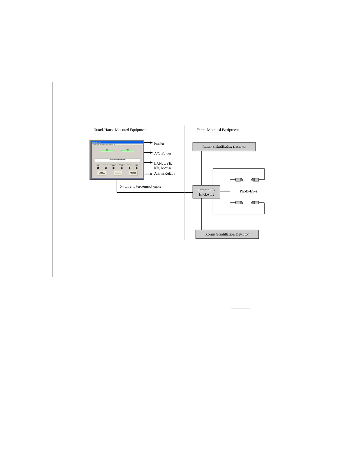
The picture above defines the major components of the Ronan XSD-1000 System:
Monitor Panel – This is the computer, display screen, touch panel, alarm relay, and
communications panel. The touch screen is for acknowledging alarms and performing a
System Verify function. Setup and options selection is via a keyboard and mouse and
requires key-lock access.
6-Wire Interconnect Cable – This cable supplies power and communications to the
Remote I/O modules, detectors, and photo-eyes.
Remote I/O Enclosure – This is a small NEMA 4 enclosure that houses the Remote I/O
modules. There is one module for each detector, and one or two digital modules for the
photo-eyes (depending on how many photo-eyes you have), and one or two relay output
modules for optional controls.
Scintillator Detectors – These are the large, crystal and electronics packages. They detect
nuclear radiation and report the results to the Scintillation Input Remote I/O modules.
3
Page 5

Photo-Eyes – These are in pairs. Each pair has one Transmitter and one Receiver.
Typical systems have two pairs of photo-eyes, one pair at each end of the Scintillation
Detectors. They are wired to the Digital Input Remote I/O modules.
4
Page 6

Operational Overview
The XSD-1000 Monitoring System executes on a Microsoft Windows XP Embedded-
based operating system. The embedded software is intended for use strictly as a
monitoring device. The hard disk is divided into two partitions: one for the operating
system and associated programs (Drive C) and one for the XDS-1000 data files (Log,
Configuration, and History files, Drive D). The primary partition (operating system and
associated program files) is typically write-protected. This ensures that unauthorized reconfiguration of the operating system or unauthorized driver installation will be discarded
at the next system boot (power off and on cycle).
If you wish to configure the system see the appendix section Operating System
Configuration for hard disk access (Drive C: is write-protected and contains Windows
and the XDS-1000 program files). This access will permit you to configure the system
(LAN/WAN connections, Windows printer selection, etc.), then reboot to save your
configuration settings and re-enable the disk-write protection function. For security
reasons, this appendix should be removed and stored separately from the manual to
prevent unauthorized writes to your hard disk.
The system is designed for a no-logon-required boot, and to auto-start the XSD-1000
software. Configuration changes to the XSD-1000 system do not require that the above
procedure be performed, as the configuration settings for the XSD-1000 are stored on the
non-write protected partition. A password is required to exit the XSD-1000 software.
The data files for the XSD-1000 (Log Files, and AssetMgmt file) are stored on the D:
drive of your system. These files are Microsoft Access (.MDB) standard files. If you
plan to access these files over your local network, you may want to configure the D: drive
(and/or just the Log sub-directory) as a shared drive/directory. This will allow you to
consolidate any number of XSD-1000 files into a host system running Microsoft Access.
Make sure you use a unique System ID (set in the XSD-1000 menus) for each system to
identify the file source.
When updates to your XSD-1000 system become available, you will be notified by email. They will be made accessible on the Ronan web site. Following is a typical
scenario for updating your system.
• You will need to download the file (typical file name: Update mm-dd-yy.exe) from
the Ronan web site into the directory: ‘C:\XSD-1000Update’ on the XSD-1000
system.
• Once downloaded, make sure you exit the XSD-1000 software and that no other
programs are running.
• Browse to the C:\XSD-1000Update directory and click on the file you just
downloaded. This will cause the downloaded file to self-extract the contained files.
Allow the system to extract the files into the current directory.
• Exit the extraction windows and explorer.
5
Page 7

• Within one minute, the system will recognize the files, display a prompt, save the
current files, perform the update, then re-boot the system.
• At this point, the XSD-1000 system has been updated and restarted.
Instructions for obtaining a particular update will appear in the e-mail, and be posted on
the web site.
A number of printer support files are included with the system. The XSD-1000 system
will use the printers selected in your Windows setup. Should you need to load additional
printer drivers, follow the instructions in the appendix to first disable the write-protection
manager, then install your files and re-boot the system to re-enable the write-protection
manager.
6
Page 8
Main Screen
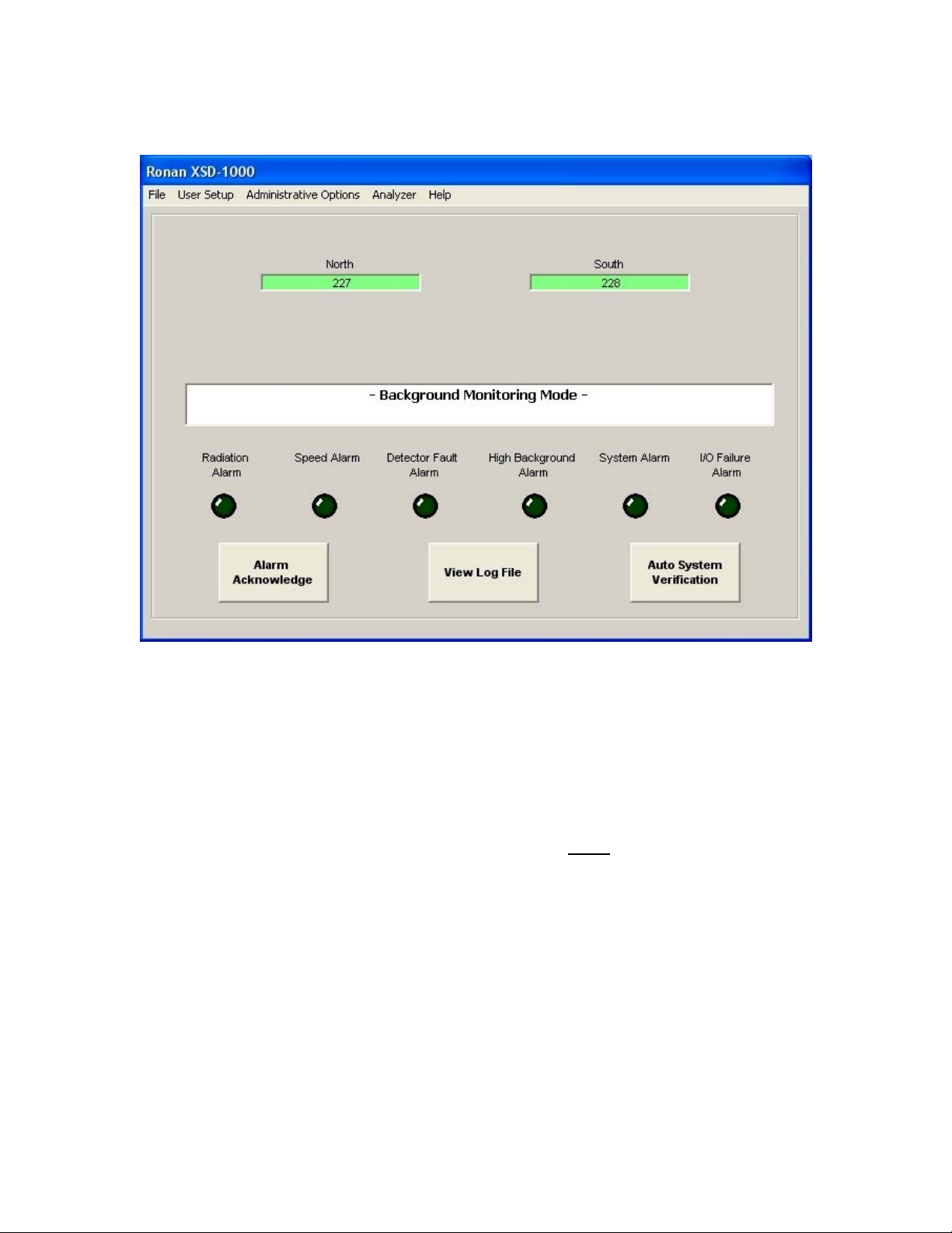
The System Title is displayed at the very top. Below the title is the Main Screen Menu
Bar. This menu bar is only displayed if the key-locked access switch is off. Clicking on
the active menu bar items grants access to the options and software setup.
Below the Menu Bar is the Detector Status box. There is a green box in this area
available for each detector position (up to 12). If a detector is enabled and functional, the
associated box will be green with the average counts displayed during Background mode
or the raw counts during Truck Present mode. If a detector is enabled, but fails, the box
will turn red with a message ‘I/O Failure’, and trigger an alarm. If you disable a detector,
its associated box will display yellow with the message ‘Disabled’ in it.
Below the Detector Status box is the System Status Bar. This bar displays the current
mode (Background or Truck Present), status, error messages, etc. It also acts as a
progress bar during startup and detector stabilization.
7
Page 9
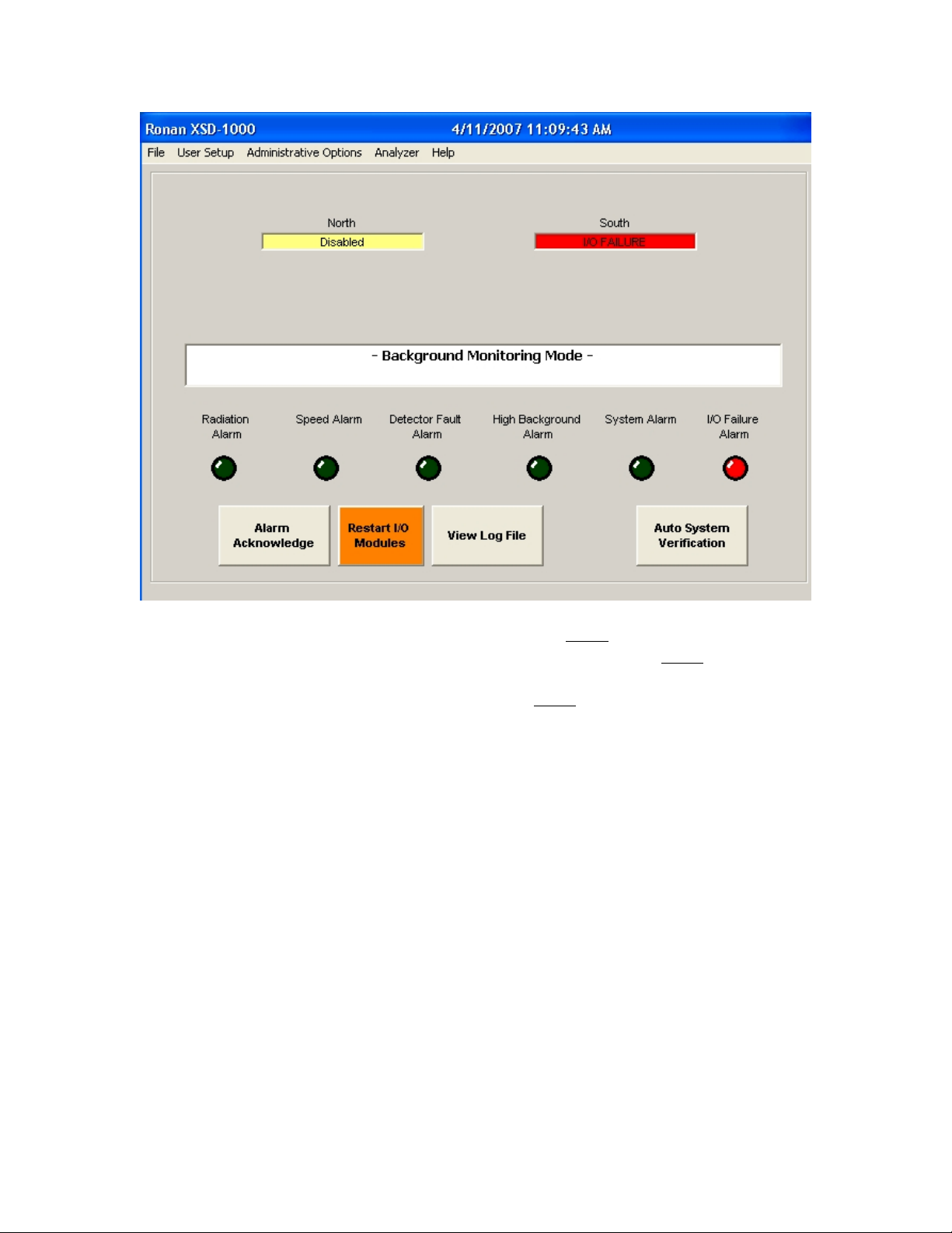
Below the System Status Bar are the Alarm LEDs. If an alarm is triggered, the associated
LED will turn red. Touch the Alarm Acknowledge button to turn the alarm off. Some
alarms, such as Detector Failure, will re-trigger on the next communications cycle, and
will require that you disable that detector to stop the alarm.
The button next to the Alarm Acknowledge is the Restart I/O Modules button. This
button will appear on an I/O failure to permit restarting the communications when the
failure is remedied.
Next is the View Log File. Pressing this button will bring up the current Log File. To
view other Log Files, use the mouse to access the File – View Log File menu item.
The last button is the Auto System Verification touch button. This is for activating the
Automatic System Verification function periodically and performing integrity tests on the
detectors, photo-eyes and alarm relays. This Auto System Verification function will
automatically progress through the tests (if each one is successful) for one-man operation.
8
Page 10
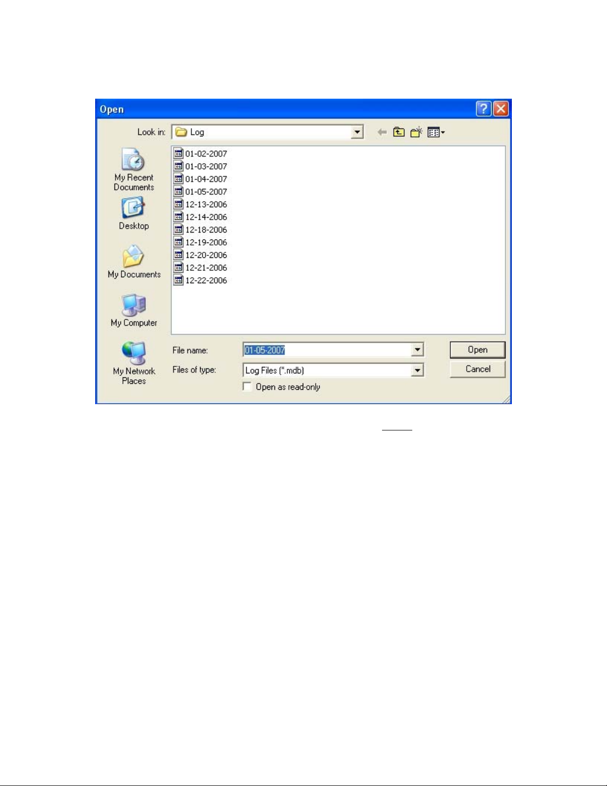
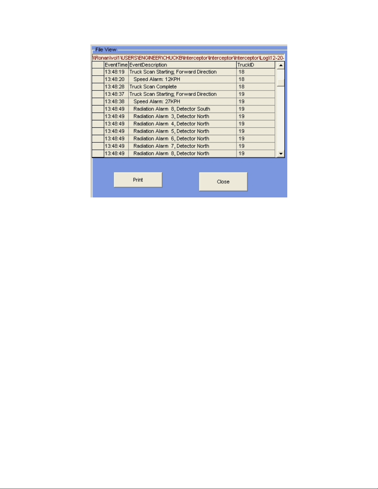
Log File Viewing
The Log File is a hard disk file that is written to based on the events you have enabled in
the User Setup-Events Logging options. All selected events will be written to the file if
and when they occur. This is a Microsoft Access file that can be printed, viewed
outside the XSD-1000 software, and/or sent over a communications line to another
computer.
Selecting the File-View Log File menu entry brings up the above display of all log files
stored on your system. You can select which file to display.
If you select the View Log File hot button on the main screen, only the current active log
file will be displayed.
9
Page 11
The current Log File name will be the current system date. For example: 05-25-
2006.mdb. The file will be created when the system is initially powered up, and when
the expiration time elapses. The expiration time is set up in the Administrative Options –
File – Log Files Creation menu.
If the system is powered down, then powered back up in the same day, the system will reopen the same file and append to it. The current Log File is the default.
Use the scroll bar on the right side of the display to view events beyond what the screen
is displaying. If you have the Image Capture option, there will be a window to the right
of the data display. This window is for viewing captured images from a camera when a
particular alarm event has been selected.
If an alarm condition is listed for a particular Truck ID, you can click (or touch) the
Truck Scan Starting entry to display the Approximate Source Location picture as
displayed after a Truck Present Cycle when an alarm occurs.
10
Page 12

User Setup
This set of menus allows non-password protected options. These options (other than the
Detector Status) typically do not affect local system operation.
11
Page 13
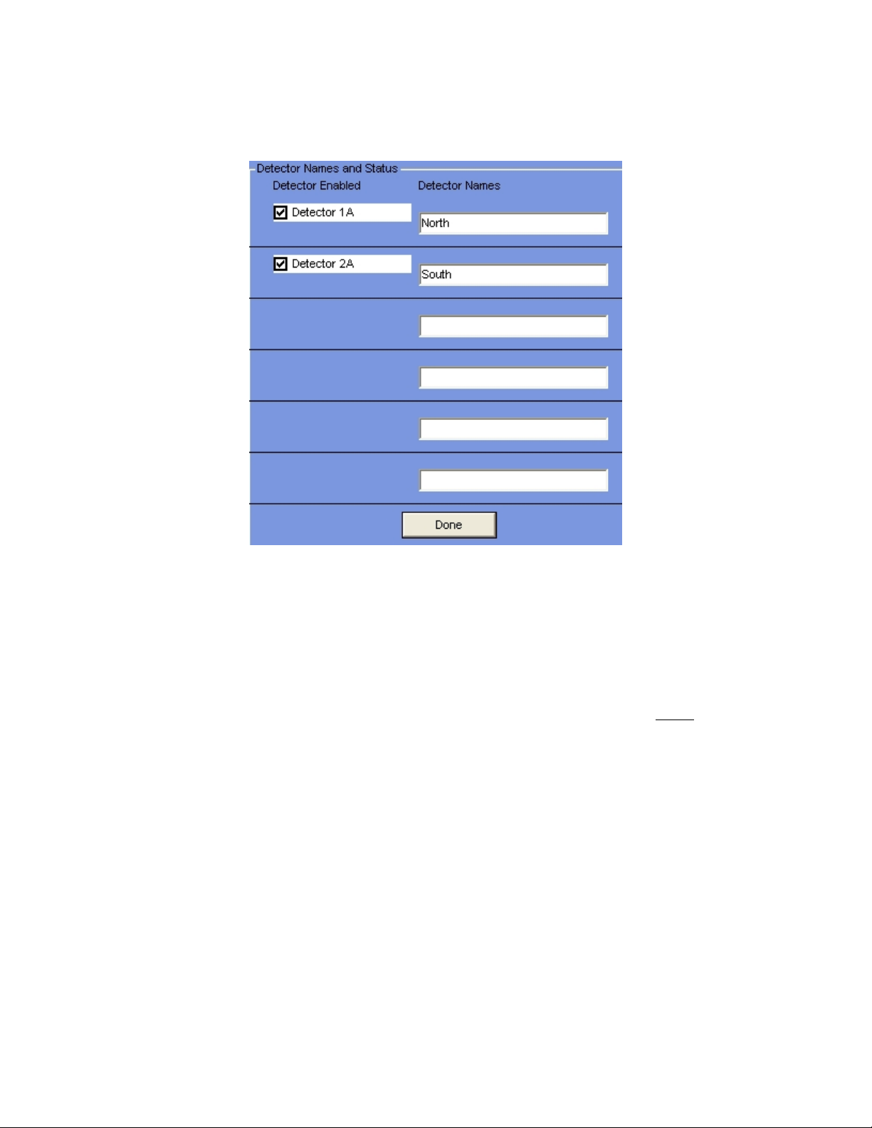
Detector Names/Status
NOTE: the number of detectors displayed here is defined in the Administration Menus
under Configure – Detectors. This should be done before enabling any detectors.
Enter the names of each detector for clarity (North, Top, etc.), and each detector’s status
(Enabled/Disabled). Each detector should have a unique name for identification
purposes. The names you select will appear over the green box displaying that detector’s
averaged counts during Background mode, and the raw counts for that detector during
Truck Present mode. The names will also appear in the Log File report if an alarm occurs
for that detector. To change the Detector Names, highlight the name in the box, and type
in the new name.
All operational detectors’ status should be ‘Enabled’. Use the ‘Disable’ function if a
detector fails in order to disable constantly triggering the I/O Failure Alarm, until the
detector problem is resolved.
To change a detector’s status (Enabled/Disabled), click on the box. A check mark means
Enabled, a blank box means Disabled.
The detector values next to each check-box under the ‘Detector Enabled’ column are the
names used to wire the detectors to the proper Remote I/O modules (1A, 2A, etc.).
12
Page 14
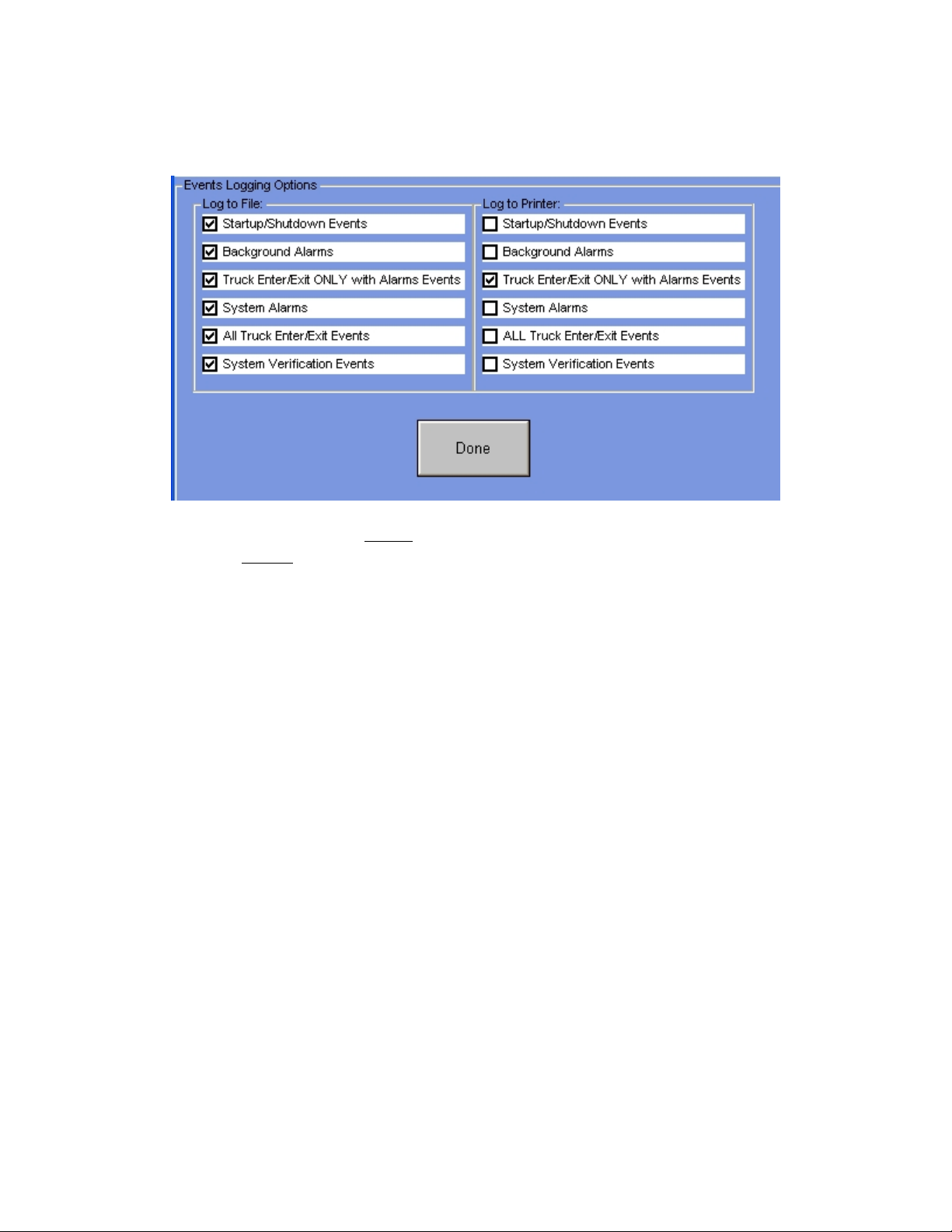
Events Logging
Use this menu to setup which events are to be logged to the Log File and which are to be
logged to the Printer. To change your choices, click on the boxes next to each choice.
A checked box enables logging the selected event to the device.
13
Page 15
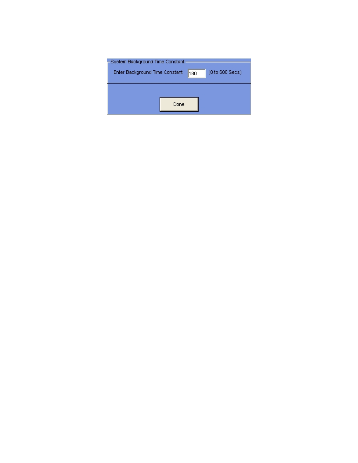
Time Constant
This is the Time Constant for Background Averaging. This number is usually about 180
seconds (3 minutes). Background radiation changes are slight and slow, and a long time
constant is required to reduce the statistical noise.
It acts as a digital filter on the raw counts to establish the baseline for all detection
activities. The long time constant value filters the raw signal, yet permits the system to
constantly calibrate itself through background changes between day/night and seasons.
14
Page 16
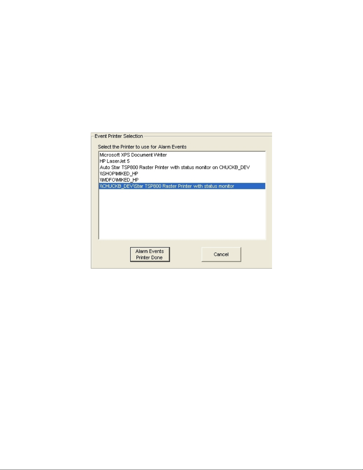
Select Printers
In this menu you can select the printer to be used for Alarm Events, typically during a
Truck Present cycle. This could be a ticket-style printer since each truck event can have
its own ticket. A separate printer can also be selected for your reports. Either of these
selections can use local or networked printers.
At power up, if no printers have been selected or your previous selection is not available,
the system will assign the printer(s) to the Windows default printer. A warning block
will appear at startup if your previous selection is no longer available.
On the first frame, you select the printer to use for Alarm Events. This includes all alarm
events enabled in the Events Logging user menu. Click on your choice and then click on
the Alarm Events Printer Done button to continue. Clicking on the Cancel button aborts
with no action being taken.
The same menu will appear and but now expect you to select the printer for reporting.
15
Page 17
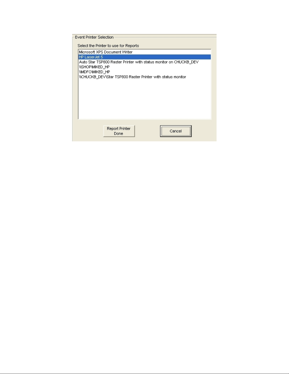
You can select any printer from the list (including the same one used for Alarm Event
printing). Click on one of the selections in the list then click on the Report Printer Done
button to save your selection.
This selection is used for reports such as the Log Files, Analyzer graphs, and the reports
available in the Quality Assessment section.
16
Page 18
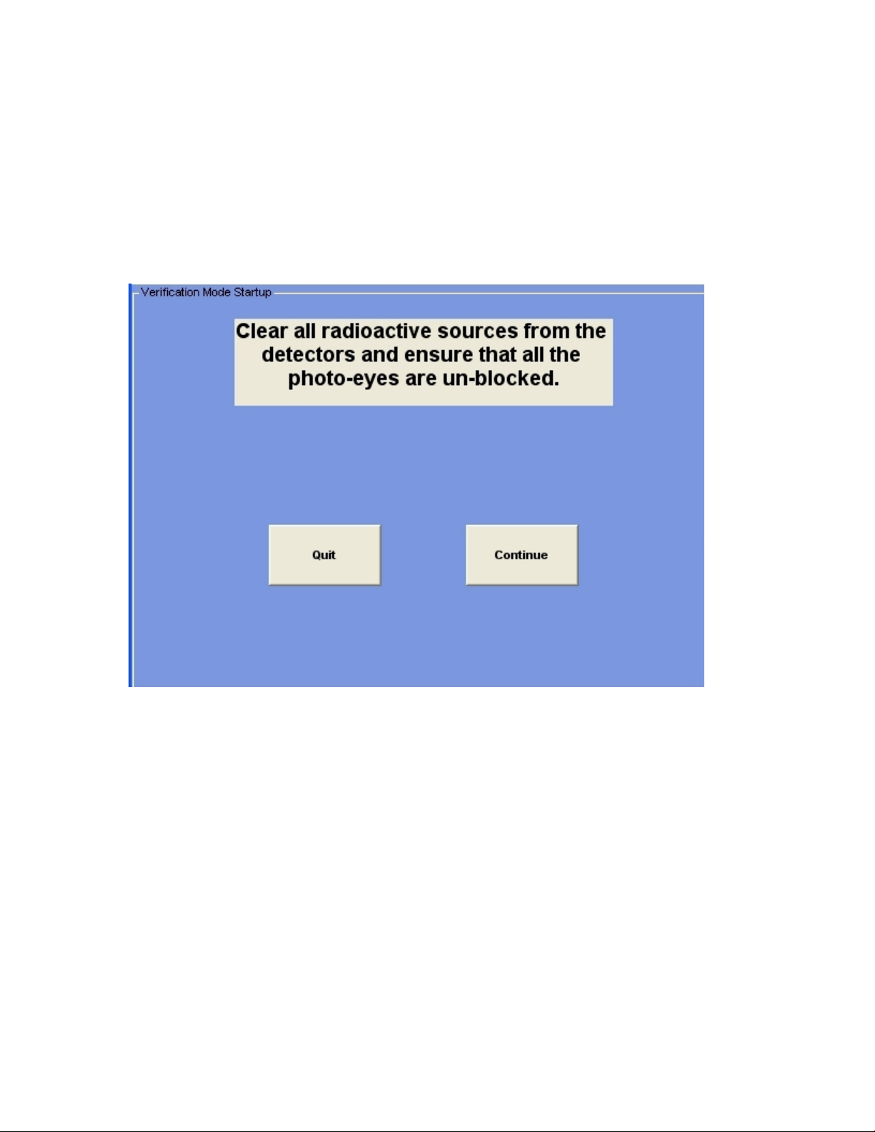
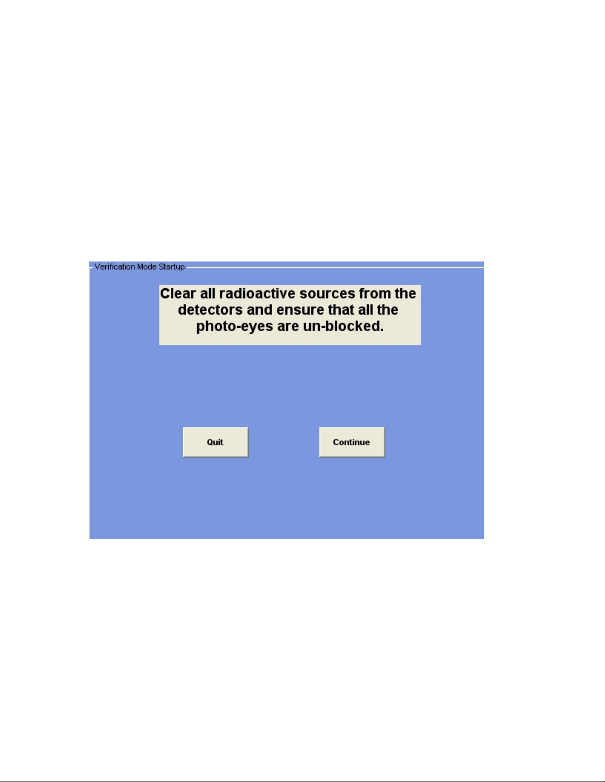
Manual System Verification
The major components of the system can be periodically checked with this function. It
should be performed regularly to ensure the integrity of the monitoring system. This
selection allows you to select the parts of the system you wish to verify:
• Detectors
• Photo-eyes
• Relays and internal beeper
The first screen you encounter is the above with preparation instructions. Clicking on the
Quit option will abort the function.
17
Page 19
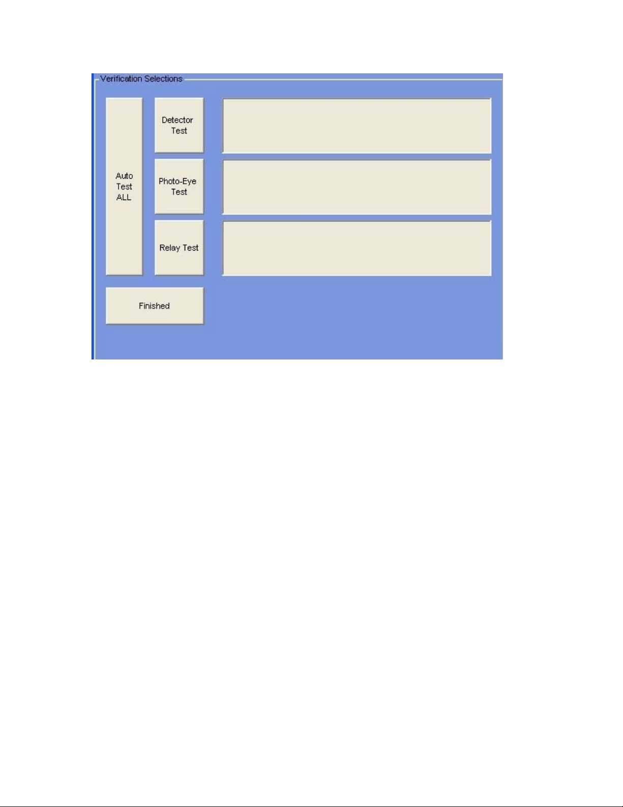
This is the selection screen. You can select the parts of the system you wish to verify
here. Each selection will test one of the three functions. Clicking on the Auto Test ALL
button will run an Auto-Test on all three functions (the same as the touch-button
AutoVerify” on the Main Screen).
18
Page 20
Auto System Verification
When you select the Auto Verification function (right-most touch-button on the Main
Screen), the system will auto-finish the Detector and Photo-Eye Verifications if all
functions in these categories pass. This allows you to start the Verification, go to the
Truck Path, test each detector, test each photo-eye, then return to the Monitor Panel, test
the Alarm Relays, and ensure that each function passed.
An optional relay output at the detector frame is available when the detector frame is not
located conveniently to the Monitor Panel. This output will energize for a few seconds
when all detectors have passed, and when all photo-eyes have passed (in Auto
Verification mode), to allow an audible or visual indication of the Auto Verification
process. This output is on the Relay Output Remote I/O Module, Output Number 1.
This screen allows you to continue or abort the Auto Verification process. If you click
(or touch) the Continue button, the system will begin the Detector Stabilization process,
then start the Detector Verification process.
19
Page 21
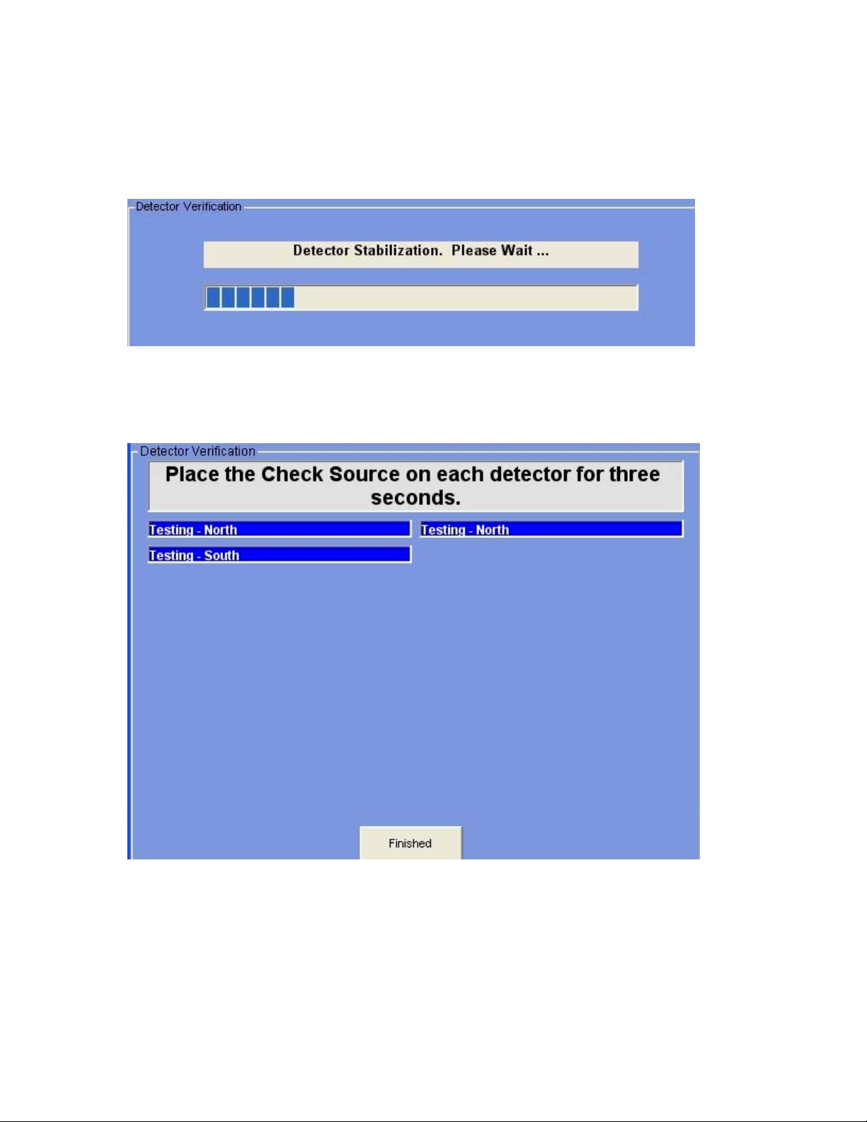
Verify Detectors
When you select Verify Detectors from the Manual Verify screen, or press the
AutoVerify button on the Main Screen, you will be presented with the following screen:
In order to perform any detector test, the system must get a stabilized value from each
detector. The progress bar will inform you of the time remaining before testing can
begin.
Once the stabilization has completed, each detector that has been activated and is enabled
will be available for testing. You must place the Test Source supplied with your system
on each detector for three seconds. If the detector is working correctly, the displayed box
for that detector will change to a green color and read “Passed”. In Manual Verification,
you must click on the Finished button to continue, when all detectors have been tested.
In Auto Verification, if all detectors Pass, the system will continue to the Photo-Eye
20
Page 22

Verification automatically. The results of the verifications will also be recorded in the
Log File and Printer if selected in the Events Logging menu.
21
Page 23
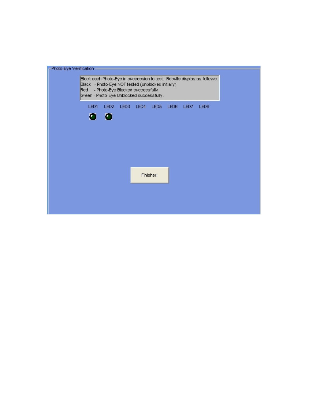
Verify Photo-Eyes
This function ensures the correct operation for each of the Photo-Eyes in your system.
As you walk through the Truck Path, each photo-eye will be blocked, then unblocked.
The blocking and unblocking will be recorded on this screen. When a photo-eye is
blocked, its associated LED on the screen will turn Red. After being blocked, when a
photo-eye is unblocked, its associated LED on the screen will turn Green.
If you are Manually verifying the system, click on the Finish button when done. If you
have selected Auto Verification, the system will move on to the Relay Verification
automatically after toggling the Verification Annunciator relay for a second or two, if all
photo-eyes pass (turn Red, then Green).
22
Page 24
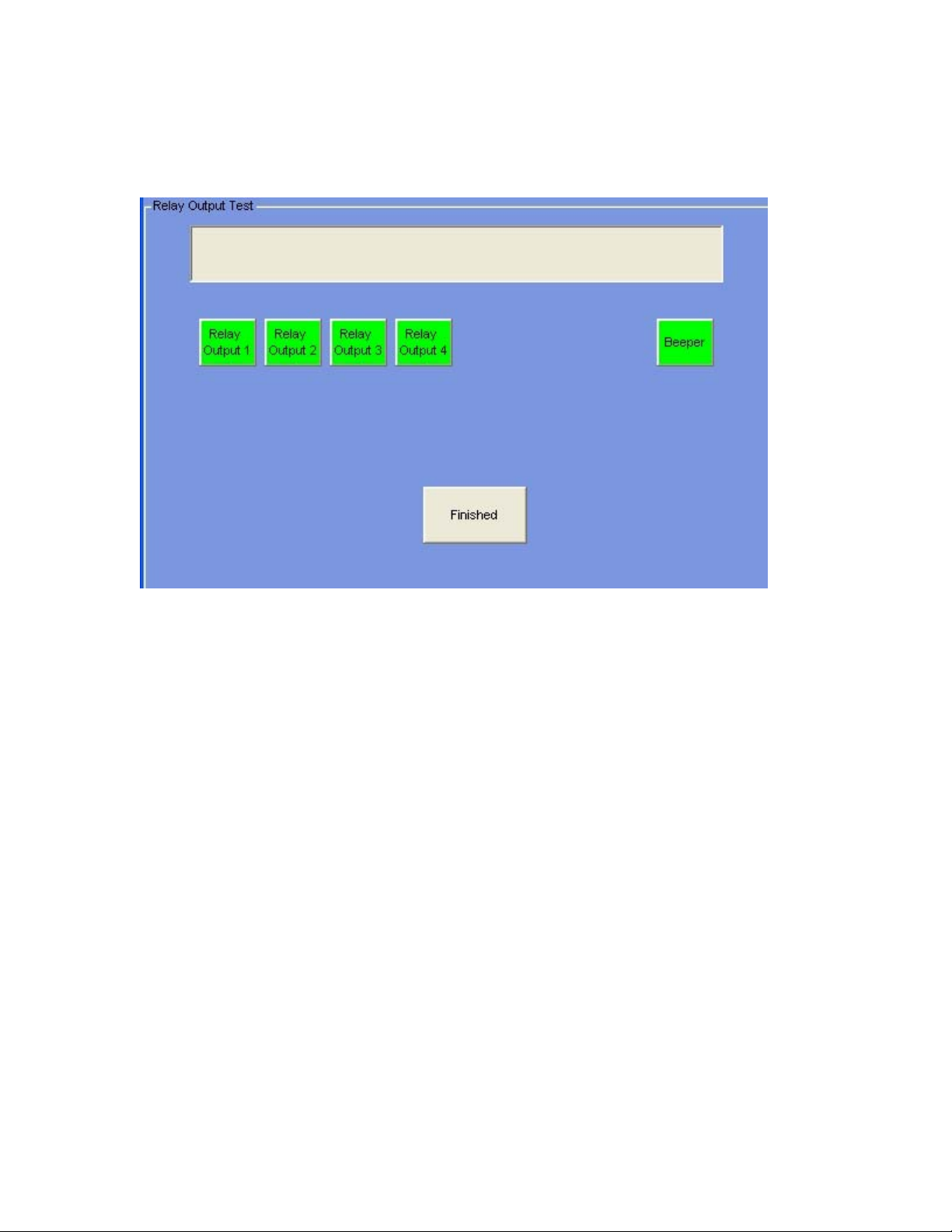
Verify Relays
This verification function will allow you to test each of the relay outputs.
Each Green relay (or beeper) box you click on will initially turn Red (and energize the
relay or internal beeper). Any annunciators you have tied to the relay should also be
activated. Clicking on a Red box will turn the relay (or beeper) box to Green (and deenergize the relay or beeper).
Whether you have selected Manual Verification or Auto Verification, you will need to
click (or touch) the Finished button here to complete the Verification Process (or return to
the Manual Selection screen).
23
Page 25
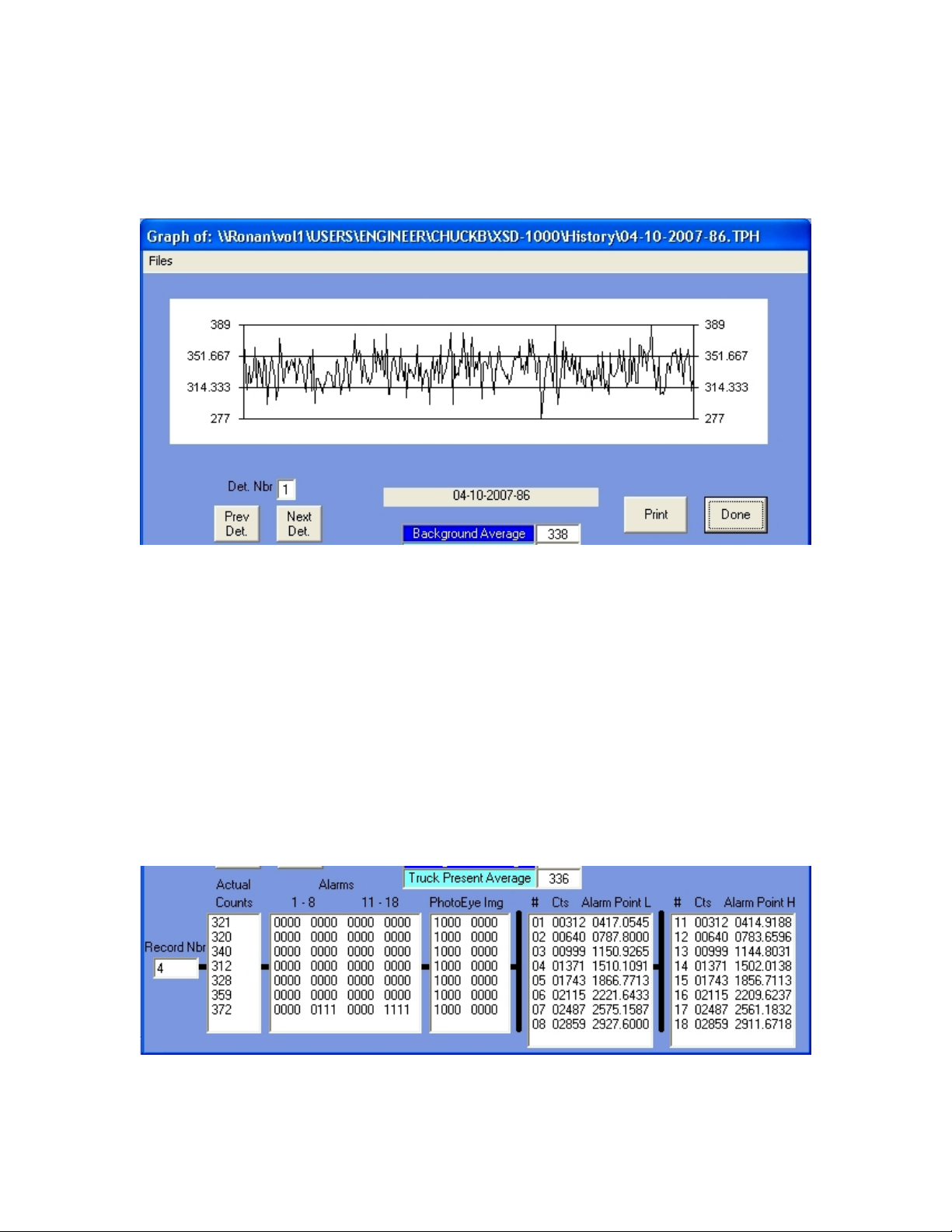
Analyzer
The Analyzer function allows you to graphically view the Truck Present cycle counts
from the detectors. This is primarily used for system tuning on special applications.
When a file is opened (if the Truck Present History is enabled) or the previous Truck
Present cycle is viewed, the counts from the detector (default is Detector 1) are
graphically displayed.
By clicking on specific points on the graph, the bottom list boxes will scroll to that point
(as indicated by the horizontal bar next to the lists). When you click on a point in the
graph, notice the second list box from the left. If any alarms occurred on that point, a ‘1’
will appear under the appropriate alarm (1-8 or 11-18). You can select other detectors by
selecting the Previous Detector button or the Next Detector button. The graph can also
be printed by clicking on the Print button.
There is a natural attenuation in counts due to the truck bed blocking the background
counts, so a Truck Present Average is generally lower than the Background Average.
24
Page 26

As you select different points on the graph, the record number in the far left of the bottom
portion will change. A record represents one sample period of time. The actual counts
for this detector is listed next.
There are 16 possible alarms per detector. The first 8 alarms are based on the
Background Average, and the next 8 are based on the Truck Present Average. A ‘1’ in
any row in the Alarms box represents the level of alarm in that column.
The next box represents the photo-eye image from the photo-eyes. A ‘1’ in a column
represents that photo-eye being blocked, and a ‘0’ represents the photo-eye unblocked.
The leftmost digit is photo-eye number 1.
The last box lists the alarm number (1-8 and 11-18), the counts from the detector (and the
summed counts over time for alarms greater than 1 or 11), and the alarm point for each
alarm. Obviously, a count greater than its alarm point is an alarm condition.
25
Page 27

Administrative Options
These menus are password protected. Entering a valid password will gain you access to
the Administrative options.
These options are primarily used for initial setup or system upgrades. Once setup, there
is little need for future access.
The Administrative Options permit changing the number of detectors, photo-eye
configuration, background and truck present alarm functions, passwords, speed alarm
options and the Quality Assessment functions. The history sampling can also be changed
from the Administrative Options menus.
One important function in the Administrative Options is saving your current
configuration. After setting up the User Options and the Administrative Options, you
should access the Administrative Options – File – Save Current Settings to Disk File and
save the current configuration settings. This can be important for later use in upgrades,
repairs, restoration, etc.
The default passwords for the Administrative Functions are:
• admin
• password
• access
These can be changed and managed in the Administrative Options menus.
26
Page 28

History Files
These selections determine if the system will record the files of counts received during
Background and/or Truck Present mode. This is normally a diagnostic function used by
field service in the event of a problem. Enabling these options will require substantial
disk space over time. Click on the box to enable (checked) or disable (unchecked) the
option.
If you do not know if you need these options, disable them. If you plan to use the
Analyzer function described elsewhere, you will need the Truck Present History function
enabled. With the Truck Present History function disabled, you can still use the Analyzer
function, but you can only display the last Truck Present cycle activity. When the next
Truck Present cycle begins, the previous contents will be lost.
27
Page 29

Log Files Creation
You can select when the system should create new log files here. If you select:
• Never – the system will create a Log File at initial startup, and never create another as
long as the original one exists. Note: this file can get very large over time.
• Day – a new Log File will be created daily.
• Week – a new Log File will be created weekly
• Month – a new Log file will be created at a change of month.
• Year – a new Log file will be created at a change of year.
28
Page 30

Password Maintenance
This menu allows you to set up to 3 passwords for Administrative Options access and up
to 3 passwords for user-logout (system shutdown). The passwords can be letters and/or
numbers and can be up to 15 characters long. The passwords are case sensitive and must
be input exactly as listed in the password boxes above.
The Log Out passwords permit the user to exit the XSD-1000 software package (File –
Exit), and the Administrative passwords permit access to the Administrative Options in
the menus.
The passwords listed in the example above are the system default passwords.
29
Page 31

Save Current Settings to Disk File
This menu permits you to store your current User and Administrative options to a disk
file. Once saved, you can use the File – Restore Settings from Disk File menu item to
retrieve these settings.
You can save multiple configurations by using unique file names for each one.
Note: Do NOT overwrite the Factory.CFG file. This is the factory setup file and allows
you to recover the safe values stored by the factory.
30
Page 32

Restore Settings from Disk File
This function will restore a previously saved configuration from a disk file. Caution: the
current settings in the system will be overwritten by these values.
The Factory.CFG file contains the settings for the system that was set at the Ronan
Facility before being shipped to you.
31
Page 33

Restore Safe Default Settings
Use this option if all else fails. Initially, try restoring the settings you saved. If this fails,
restore the factory settings (Factory.CFG file). If the Factory.CFG file is not present or
fails, you can use this option (Safe Defaults).
Caution: this option will over-write any settings you have changed including the Factory
settings.
32
Page 34

Background Mode
You set the Power Up Stabilization Time here. When you start up the XSD-1000
software, the system will average the detector counts for a period of time. This is the
Power Up Stabilization Period that the system calibrates to. This value should be at least
3 minutes (180 seconds) to allow proper statistical averaging and a stable value for each
detector.
The Number of .2 Second Period Samples value should NOT be changed unless you
consult the factory first. This value represents how often the system samples the detector
readings. This value also affects the overall detector sensitivity and the number of
‘looks’ the detector has during a Truck Present cycle.
33
Page 35

Detectors
You can select which detectors you have in your system with this screen. Each detector
number is associated with a Remote I/O Module Address. If you activate a detector that
has no Remote I/O Module currently active, the system will warn you. Unless you are
upgrading your system, you should not activate detectors with no Remote I/O Module
present.
The Dual Option means that you have two detectors at that position. This is normally a
special detector with two electronic heads that act as one (or two detectors end-to-end).
Do not enable this option if you do not have actual Dual Detectors with your system.
34
Page 36

Detector Locations
In this menu, you position the detectors as they are mounted around the Truck Path. This
will permit the system to approximate where on the truck a Radiation Alarm occurred.
Initially, the detectors are listed in the upper left corner of the screen. As you view the
back of a truck in the ‘Incoming’ direction through the Truck Path. Move the mouse over
one of the detector boxes, hold down the left mouse button, and ‘drag’ the detector to its
position around the truck. It is not important how close to the truck you get (stay within
the dotted boxes). If you have a two detector system, try to get the detector boxes as
close to the vertical center of the dotted box as possible. For top or bottom-mounted
detectors, try to get as close as you can horizontally to the center of the box. A four
detector system will mean that you should try to get each detector box about 1/3 of the
way away from the top or bottom of the dotted boxes.
The following is an illustration of a two detector system:
35
Page 37

36
Page 38

Photo-eyes
The top section of this menu has three options. The first is the Total Number of pairs of
Photo-eyes (remember that photo-eyes come in pairs: one transmitter and one receiver
per pair). Most systems have 2: one at each end of the detectors. Up to 8 photo-eye pairs
can be accommodated.
The next option is the distance between the photo-eye pairs. This distance is in Feet (if
MPH speed is selected in the Admin – Alarms Setup - Speed Alarms Menu) or Meters (if
Km/Hr is selected) and is measured along the vehicle path (not across it). The typical
distance is 6 - 10 feet.
The final option at the top is the selection of Unidirectional or Bi-directional operation.
If you are only checking vehicles in one direction (for instance: coming into the facility
only), then select unidirectional. If you plan to check vehicles in both directions (for
instance: entering and exiting the facility), then select bi-directional. Note: if you have
only one photo-eye pair, do not select Bi-directional. The system cannot distinguish both
directions with a single photo-eye pair.
You must now determine your directions for clarity. If you selected a unidirectional
system, the right side of the above display will be blank. Facing the XSD-1000 Frame
and Detectors from the Monitor Panel location, determine which direction vehicles will
pass through the system and define a name for that direction (ie: Incoming, Entrance,
etc). For instance, as you face the XSD-1000 Frame and Detectors, if vehicles enter the
system from left to right as they enter your facility, you could call this direction
‘Entrance’, or ‘Forward’. Whatever name you choose will be used on-screen and in the
Log Files and Printer Logs to determine the direction of a Truck Present cycle.
37
Page 39

There are 5 boxes below the photo-eyes that display the functions of the photo-eyes. The
first one is highlighted initially. To select other functions, click on the definition boxes
and the photo-eyes enabled for that function will be shown.
The number of photo-eyes you selected previously determines how many lights are
available below the name you select. Each light represents a photo-eye. A ‘black’ light
means it is not selected; a ‘green’ light means it is selected. The light with the box
around it represents photo-eye number 1. The others are numbered from left to right. As
you click on the boxes below the lights, the lights will change to show the ones selected
and unselected. To change a photo-eye from selected to unselected or unselected to
selected, click on the photo-eye you wish to change. The photo-eye numbers on the
screen match the numbers on the Remote I/O Digital Input card. If you wired the leftmost photo-eye into Input #1, then number one on the screen represents the left-most
photo-eye.
You must determine which photo-eyes perform the following functions:
• Truck Present Photo-Eye: Only one light should be green here and should be an ‘end’
light (first or last). The direction the vehicle travels for the Forward Direction Name
cycle will determine which photo-eye starts the Truck Present cycle. The first photoeye blocked by the truck will start the Truck Present cycle. Click on any light to
toggle it from on to off to on.
• Photo-Eye(s) ON to Maintain Truck Presence: These are the photo-eyes that must be
on to maintain the Truck Present cycle. If any of the lights defined here remain
blocked, the Truck Present cycle will continue. All the photo-eyes selected here must
be off during a Truck Present Cycle to end a Truck Present cycle.
• Photo-Eyes for Speed Checking: Any photo-eye not used to start the Truck Present
cycle for this direction should be used for speed checking.
• Photo-Eye at Starting end of Detector: This could be the same photo-eye that starts a
Truck Present cycle (if you only have two photo-eyes on your system). There is one
photo-eye at each end of the detector. The one the vehicle will block first in this
direction should be selected here. This gives the system the knowledge it needs to
calculate the Alarm Points properly.
• Photo-Eye at Far End of Detector: This is the photo-eye at the other end of the
detector used for Alarm Point calculations.
If you have a bi-directional system, you will need to set the Reverse Direction Name
section up like you did the Forward Direction Name section. Keep in mind that the
vehicle is now moving in the opposite direction, and the photo-eye settings for the
Forward section should be a mirror image of this section.
38
Page 40

Now you must select the picture that represents which way the vehicle will be moving in
the Forward Direction Name direction. Click below the picture to change the direction.
This picture will be displayed in the event of a vehicle alarm, and an approximate
location of any source material will be displayed.
39
Page 41

Relay Output Options
You have 4 relays and an internal beeper available on each XSD-1000 system. This
option allows you to select the relay that will trip on the alarm specified. You can select
the same relay for all alarms, or split them up. Click on a blank box to check it, or on a
check mark to deselect it. Any relay can be set to activate on any, all, or none of the
events listed.
Each relay is a Form ‘C’ type contact arrangement (N.O., N.C., Common).
The beeper (located on the underside of the Monitor Panel) can also be programmed to
alarm on any, all, or none of the events.
40
Page 42

System ID
This is the title displayed at the top of the main screen. It is also used in the
communications function to identify this XSD-1000 system. If you have multiple XSD1000 systems communicating to a host (or server), the System Identification for each
must be unique.
The value here can be anything you decide, up to a maximum of 50 characters.
The Log Files from each XSD-1000 system can be uploaded to a host system over the
Ethernet link and ‘linked’ into a Microsoft Access file. The unique System ID will
help organize this combined file.
41
Page 43

Background Alarms
The default values for this menu should not be changed without consulting the factory.
The Detector Low Count Failure is the lowest number of counts you can receive from an
active detector. This value is typically 1.
The Consecutive Failures till Alarm ensures that you do not get false alarms in a very low
background radiation area.
The High Background Alarm Multiplier should always be 3. If the detector counts
suddenly peak above the background average by this amount (3 times background
average), then the detector will fault after the Consecutive Number of Faults. This alarm
is to ensure that radioactivity introduced to the detectors during Background mode does
not affect the sensitivity or calibration of the system.
The Consecutive Failures till Alarm behaves the same as above, except here it applies to
a High Background Alarm.
42
Page 44

Speed Alarms
The top item in this menu is the speed units. Select either MPH or KPH for your use.
Notice that the Maximum Speed will be automatically changed based on your selection.
After your units selection, type in the correct speed in the second section.
The maximum speed for vehicles is typically 5 MPH (8 KPH). Unless otherwise
instructed by Ronan factory personnel, this value should remain at 5 MPH (8 KPH).
Speed detection is performed using photo-eyes. In a single photo-eye pair system, speed
checking cannot be performed.
43
Page 45

Truck Present Alarms
The first box defines whether alarms are enabled during a Truck Present cycle. This
option should always be selected.
The Truck Present ‘ON’ Delay is for delaying the start of Truck Present cycles and is
primarily for applications where trucks may stop on a weight scale after triggering the
Truck Present Photo-eye. This value will delay the start of the cycle. Normally, the
value here is zero.
The Maximum Truck Present Time should always be 60 seconds. This value minimizes
false alarms due to the statistical algorithms used.
The Truck Present ‘OFF’ Delay value is used to maintain a Truck Present cycle when the
photo-eyes may become unblocked between the cab and trailer of a truck. If the gap
between a cab and trailer exceeds the distance between your photo-eyes, use this value to
compensate such that at least one photo-eye is blocked during the truck cycle.
44
Page 46

The bottom section should never be changed except under factory direction. The Sigma
Values and Reduction Factors directly control the sensitivity of the XSD-1000 system.
45
Page 47

Quality Assessment
The Quality Assessment functions of the XSD-1000 is intended for users requiring
periodic assessment of the system’s functionality for ISO or insurance purposes. This
functionality will allow you to track initial installation of the detectors and their output
values, then track them periodically and compare any differences. The system will
automatically calculate a valid differential from period to period including the Test
Source decay.
Multiple reports are available to check all replacement activities and dates of detectors
and Test Sources.
If you plan to use this feature, you should ensure that immediately after installation and
before commissioning the system, that your detectors and Test Source are listed in the
activity report. This information will be required after the first period to enable the
system to compare the results and determine the validity of the detectors.
You also need to set up the interval for this periodic test. After the interval time elapses,
a warning box will appear on the Main Screen reminding you that your periodic
assessment is due.
46
Page 48

Reports – Events by Date
This report will list all Detector or Test Source replacements (or installments) and all
Detector Sensitivity Checks by the date they were performed. The data is identical to the
report of Events by Type, except arranged by date.
There are three event types that can be presented:
• Replace Detector
• Replace Check Source
• Detector Sensitivity Check
47
Page 49

Reports – Events by Type
This report will list all Detector or Test Source replacements (or installments) and all
Detector Sensitivity Checks by the Event Type. The data is identical to the report of
Events by Type, except the event types are grouped together.
There are three event types that can be presented:
• Replace Detector
• Replace Check Source
• Detector Sensitivity Check
48
Page 50

Reports – Detector Sensitivity Checks
This report will list the last Sensitivity Check performed compared to the one previous to
it, and give an assessment of pass or fail by comparing the percent difference between
these two readings. The ‘First’ value will also be listed as a reference.
Note that if you replace a detector, it becomes the current with no history when a
Detector Sensitivity Check is performed. Immediately after replacing a detector, a
Sensitivity Check should be done for that detector to establish a reference for the normal
periodic Sensitivity Check to determine its validity.
The report has two halves: the left half is based on background averages (or Norm).
This test verifies the low-level sensitivity of the detector. The right half is an assessment
with your Test Source, and validates the gain of the detector. It is important to perform a
‘Replace Test Source’ at system installation so the system can determine the amount of
source decay to apply when performing the periodic Sensitivity checks.
The above report shows that only one Detector Sensitivity Check has been performed.
Therefore, there is no ‘Delta%’ nor ‘Allow%’ nor ‘Passed?’.
49
Page 51

Note the above Detector Sensitivity Report has 2 entries for each detector. You can see
slight differences between the Now and the Prev values on the Test Source half of the
report (Now is the last Detector Sensitivity Check). The Delta% if the percent difference
between the Now and Prev readings. The Allow% is the allowance percentage difference
the Now and Prev readings. In the P? (Passed?) column, both detectors passed both the
Background and Test Source Checks.
If your checks produce an N value (not passed), call Ronan Service to get the detector in
question serviced. The Passed? Column has the following possibilities:
• Y = Yes, this detector passed both the current test, and the longevity test
• N = No, this detector failed the current test (Now compared to Prev)
• ? = Not enough data to evaluate this detector
• R = The detector has failed the longevity test. Contact Ronan Engineering to get this
detector Refurbished.
50
Page 52

Set Sensitivity Check Interval
This menu allows you to establish your periodic interval for the Detector Sensitivity
Checks. After the number of Days from the Start Date, the system will prompt you (on
the Main Screen) daily as a reminder to perform the Detector Sensitivity Check. When
you perform the Detector Sensitivity Check, the Start Date will automatically be updated
to that date.
51
Page 53

Replace Detector
At initial installation, or when a detector is replaced (new or after service), you should
perform a Replace Detector function. The detectors available according to the
Administrative Options – Configure Detectors setup will determine which detectors are
listed. Note that on initial installation, you may not have Serial Numbers listed for the
detectors. This is normal.
To log replacing (or installing) a detector, you click on one of the detectors in the left
box, and it will be displayed in the box under the ‘Replace’ label. You must then supply
the Serial Number (or S.O. number) listed on the detector. Next supply your initials and
click the ‘Done’ button and this detector will then be added to the Quality Assessment
Events, and will be used (instead of the replaced detector) for future Detector Sensitivity
Checks.
52
Page 54

Replace Test Source
To initially install (or eventually replace) a Test Source, you use this menu. Typically,
the information required here is listed on a tag on the Test Source. This information is
necessary for the system to determine the amount of source activity decay between
Detector Sensitivity Checks to determine a proper Allowance Percent for the check.
• Click on the arrow (on the top box) and select the type (isotope) of Test Source you
are installing (or replacing with).
• Type in the Test Source Field Strength in uCi (micro-Curies).
• Enter the date on the Test Source.
• Enter the Serial Number from the label on the Test Source.
• Finally, enter your initials, then click on the ‘Done’ button
The information you entered will be entered into the Quality Assessment Event log.
53
Page 55

Perform Detector Sensitivity Check
The Detector Sensitivity Check is a check on the quality of the measurement and the
sensitivity of the detectors in your system. Tracability and performance checks are
typically required by ISO and insurance organizations. The Detector Sensitivity Check
function will check the detectors attached to your system and maintain a log of the checks
performed for tracability.
The first screen is informational only. If you choose to Continue, the next screen will
appear.
On the second screen, a list of enabled detectors is presented. You may select any or all
of the detectors to perform the Sensitivity Check on. If done on the interval specified in
the Set Sensitivity Check Interval menu, all detector should be checked. If you have just
54
Page 56

Replaced a Detector, you can select only the one you just replaced. If you click the ‘All’
box, all detectors will be selected automatically.
You must enter your initials before the system will accept the Continue button. Note:
clicking on the ‘Quit’ or ‘Abort’ button at any screen during the Detector Sensitivity
Check function will quit the function and write nothing to the Quality Assessment Event
log file.
After selecting the detector(s) to check, click on the Continue button and the next screen
will appear.
The system is preparing to perform a Background Radiation test on the detector(s) you
selected. Ensure that the Test Source and any vehicles or trucks are not near the detectors
before clicking on the Continue button.
During this time, the system is obtaining a Background Radiation average for each
detector you selected previously. Upon completion, the next screen will appear
automatically.
55
Page 57

The system will automatically select the detector to check. Place the Test Source on the
target on the selected detector (the one with the arrow pointing to it), and press the
Continue button. The check for this detector will run. At the conclusion of that test, the
next detector will be selected, and you then move the Test Source to the newly selected
detector. This procedure will repeat until all detectors you selected have been checked.
After the last detector has been checked, a message will appear telling you that all tests
are complete, and to press the Continue button. Pressing the Continue button will cause
the system to write the test results to the Quality Assessment Event log file and display
the Detector Sensitivity report on the screen. Today’s date will also replace the previous
date in the Sensitivity Check Interval.
56
Page 58

TroubleShooting Guide
This troubleshooting guide will help you troubleshoot problems based on the failure you
receive from the system. Refer to the Overview section for system component definitions
such as Monitor Panel, Remote I/O Enclosure, etc, as the Troubleshooting Guide will use
these definitions to refer to the components of the system
57
Page 59

No Remote I/O Modules Found
Normally when starting the XSD-1000 System, the System Status bar reads ‘Verifying
Connected I/O Modules’ for a few seconds, then starts the ‘Power Up Stabilization’. If
during the initial verification function, the system cannot locate any Remote I/O
Modules, a large orange button appears and asks you to check the modules and cabling,
then click the orange button to restart.
• Check the voltage on TB-2 terminals 4 & 5 on the bottom of the Monitor Panel. It
should read between 4.75 VDC and 5.25 VDC. If not, remove the wire from pins 4 &
5, and recheck the voltage at the terminals. If the voltage is between 4.75 VDC and
5.25 VDC, check the cable for a short or miswiring (see diagram below). Click on
the large orange button on the screen, and verify that the green LED on the bottom of
the Monitor Panel is flashing while the “Verifying Connected I/O Modules” status is
displayed. If not, disconnect the Remote I/O Cable from TB-2 terminals 2 & 3 and
re-check the green LED (you will probably have to click on the Orange ‘Restart’
button on the screen). If the LED is then flashing, there is a short in the Remote I/O
Cable, an open wire in the Cable, is miswired, or there is a problem in the Remote I/O
Enclosure. If the LED is still not flashing, replace the Communications board in the
Montor Panel.
• The following wiring diagram illustrates the correct wiring between the Monitor
Panel and the Remote I/O Enclosure:
58
Page 60

Remote I/O Failure
There is one I/O module for each detector in your system, plus one module for photoeyes 1 – 4, and another for photo-eyes 5 – 8. For instance, if you have 2 detectors and 2
photo-eyes (typical system), you will have 4 Remote I/O Modules (the fourth is the Relay
Output for Auto Verification Notification). The Remote I/O Module numbers listed in
the Log File are defined in the Remote I/O Module Addressing section.
• Check the Monitor Panel screen and the current Log File to determine if only one
Remote I/O Module has failed, or if ALL Remote I/O Modules have failed. If all have
failed, go to Step 1 in the ‘No Remote I/O Modules Found’ section.
• Open the Remote I/O Enclosure and notice the red LED’s on each of the Remote I/O
Modules. Any that are NOT flashing, but are on, are NOT communicating. Any
LED’s that are constantly off have lost power, have totally failed, or have an address
conflict. If you have recently added or replaced a Remote I/O Module, refer to the
‘Remote I/O Module Addressing’ section to verify the module’s address.
• Make sure the terminal screws on the Remote I/O Modules are tight and there are no
loose wires.
• Remove the power from the Monitor Panel for about 5 seconds, then restore it. All
LED’s on Remote I/O Modules should begin flashing within a few seconds.
• If a Module (or Modules) still cannot communicate or power up, replace the Remote
I/O Module. Refer to the ‘Remote I/O Module Addressing’ section for proper
addressing.
59
Page 61

Detector Failure
Detector Failures can come from two areas:
• Actual detector failure
• Failure of Scintillator Input Remote I/O Module power supply
(You can refer to the chart in the ‘Remote I/O Module Addressing’ for the correct I/O
Module address if you are not sure which I/O Module to look for).
• Check the Scintillator Input Remote I/O Module in the Remote I/O Enclosure to
ensure its red LED is flashing. If not, refer to the ‘Remote I/O Failure’ section.
Check the voltage at the Remote I/O Modules pins +24V & Com. You should see at
least 15VDC at these terminals. If so, proceed to the section ‘Troubleshooting the
Detector’.
• If there is no voltage at these pins, disconnect the wires to the +24V and Com
terminals and recheck the voltage.
• If you read a low voltage (less than 15VDC) or have no voltage, replace the
Scintillator Input Module.
• If the voltage is greater than 15VDC, proceed to the ‘Troubleshooting the Detector’
section.
60
Page 62

Photo-Eye Failure
Check the 12VDC (TB-2 terminals 6 & 7) on the bottom of the Monitor Panel. If there is
no voltage at these pins, remove the Remote I/O Cable from TB-2 terminals 6 & 7, and
recheck the voltage at the terminals. If there is now 12VDC at the terminals, then the
Remote I/O Cable is miswired or broken and needs replaced. If there is voltage on the
terminals, check the wires at the terminal block on the Communications board inside the
Monitor Panel. If they are intact, replace the 12VDC power supply.
To use the system with a failed Photo-eye (assuming you have more than two Photo-eyes
on your system), do the following:
If you have more than 2 photo-eyes, and a failure occurred on a photo-eye at the
beginning or end of the detector, replace it with one of the others such that the photo-eyes
at both ends of the detector are functional. Go to the Administrative Options – Configure
– PhotoEyes, click on each of the photo-eye configuration boxes, and click off the photoeye you took out. This, in effect, disables that photo-eye until you can get the failed one
repaired or replaced.
Note that it will help if you first go to Administrative Options – File – Save Current
Settings to Disk File and save your settings first. Then when the failed photo-eye is
repaired/replaced, you can go to Administrative Options – File – Restore Settings from
Disk File and retrieve you last setup before the photo-eye configuration was changed.
If you only have 2 photo-eyes, you will need to switch the system to Uni-Directional in
the Administrative Options – Configure – PhotoEyes menu. If the failed photo-eye is the
Truck Present Start photo-eye for the direction you need, you can physically swap the
photo-eyes on the frame. Unfortunately, with only one photo-eye available, the system’s
sensitivity it affected and you may get an increase in false alarms. It is imperative that
you get the photo-eye repaired/replaced as soon as possible.
As above, the failed photo-eye can be turned off using the Administrative Options –
Configure – PhotoEyes menu. Click on each of the photo-eye configuration boxes and
click off the failed photo-eye, until it is repaired/replaced.
61
Page 63

Relay Failure
This failure will probably become apparent during a System Verify (Manual or
Automatic). If a failure occurs with an Alarm Relay, go to the Administrative Options –
Configure – Configure Relay Output Assignments, and re-assign the failed relay to
another working relay. The Alarm Relays are located in the Monitor Panel and will
require repair/replacement of the printed circuit board inside the unit.
If the relay failure is a Verification Notification relay, Speed Notification relay, or a Gate
Control relay, these are located on the frame in the Remote I/O Enclosure. See the
section on Remote I/O Failure for help here.
62
Page 64

Troubleshooting the Detector
NOTE: Make sure the wiring from the detector to the Scintillator Input Remote I/O
Module is correct. If you have just replaced (or added) a Scintillator Input Remote I/O
Module when the Detector Failure occurred, refer to the Remote I/O Module Addressing
section to ensure you have properly addressed the Remote I/O Module.
• Remove the cable from the detector. This is a military style twist-off connector
located at the top of the detector.
• Make sure the Remote I/O Modules are powered up; the red LED on the Scintillator
Remote I/O Modules needs to be On or Flashing.
• Check the voltage at pins A & J of the twist-off connector. If you have greater than
14VDC at these pins, the detector needs to be repaired or replaced. Otherwise,
replace or repair the detector cable.
63
Page 65

Adding/Replacing a Remote I/O Module
When replacing a Remote I/O Module, there are two important things to check:
• Replace with the same module type (Scintillator Input, 3-30VDC Input, etc.)
• Make sure the address on the new board is correct.
You do not have to remove the field wiring to replace a Remote I/O Module, unless the
module’s connector is faulty. Pull the connector up, press the plastic release tab on the
I/O Module, remove the module and replace with a new one, and push on the connector.
When upgrading (adding additional features, detectors, etc.) follow the installation
instructions for proper addressing and wiring.
NOTE: If two Remote I/O Modules have the same address, either one or both will not
communicate properly! See the section on ‘Remote I/O Module Addressing’.
64
Page 66

Remote I/O Module Addressing
In the following illustrations, the slider on each switch position 1 – 7, should match the
black portion of each switch. For instance:
in this illustration, switch position 1 is On (up), positions 2 through 7 are Off (down).
This chart illustrates the proper addressing for each Remote I/O Module:
Module
Module Type Description Switch Positions
Address
1 3-30VDC Input Photo-eyes 1 - 4
2 3-30VDC Input Photo-eyes 5 - 8
5 Relay Output Auto Verification
Annunciator
7 Scintillator Input Detector 1A
8 Scintillator Input Detector 2A
9 Scintillator Input Detector 3A
10 Scintillator Input Detector 4A
11 Scintillator Input Detector 5A
65
Page 67

12 Scintillator Input Detector 6A
13 Scintillator Input Detector 7A
14 Scintillator Input Detector 8A
15 Scintillator Input Detector 9A
16 Scintillator Input Detector 10A
17 Scintillator Input Detector 11A
18 Scintillator Input Detector 12A
19 Scintillator Input Detector 1B (Dual
Detector ONLY)
20 Scintillator Input Detector 2B (Dual
Detector ONLY)
21 Scintillator Input Detector 3B (Dual
Detector ONLY)
22 Scintillator Input Detector 4B (Dual
Detector ONLY)
23 Scintillator Input Detector 5B (Dual
Detector ONLY)
66
Page 68

24 Scintillator Input Detector 6B (Dual
Detector ONLY)
25 Scintillator Input Detector 7B (Dual
Detector ONLY)
26 Scintillator Input Detector 8B (Dual
Detector ONLY)
27 Scintillator Input Detector 9B (Dual
Detector ONLY)
28 Scintillator Input Detector 10B
(Dual Detector
ONLY)
29 Scintillator Input Detector 11B
(Dual Detector
ONLY)
30 Scintillator Input Detector 12B
(Dual Detector
ONLY)
67
Page 69

Printer
You have the option to select which events will be printed to the printer. These options
are found in the User Setup - Events Logging menu. The same events available for the
Log File are available for the Printer. Any event checked, if it occurs, will be printed.
You may select different events for the Printer and Log File.
The optional printer supplied by Ronan is a thermal 4” wide printer with graphics
capability. Its primary purpose is to log alarm events on hard copy. Truck Present Alarm
events will be printed on an individual ‘ticket’ of paper, while other system and
background alarms will be printed when a truck arrives or when the system is shut down.
The cable interface at the monitor panel is a 25-pin male D-sub-style connector.
68
Page 70

Events
The following events can be selected for printing or logging in the User Setup menus:
• Startup/Shutdown Events: XSD-1000 program startup/shutdown
• Background Alarms: Alarms occurring during Background Mode. These include
High Background Alarms, Detector Failure Alarms.
• Truck Present Alarms: Alarms occurring during Truck Present Mode. Including
Radiation Alarms, Vehicle Speed Alarms. The Truck ID will also be printed with
these events.
• System Alarms: Program failure, Remote I/O Module failure, Communications
failure.
• Truck Enter/Exit Events: Vehicles triggering the Truck Present photo-eye(s), and
exiting the system. The Truck ID will also be printed with these events.
• System Verification Events: Summary when the System Verification is performed
either manually or automatically.
69
Page 71

Passwords
The XSD-1000 system requires a password to access the Administrative menus, and to
shut down the software. There are three passwords for each function. The default
Administrative access password is ‘admin’. Once accessed, the Administrative
Passwords should be changed for security reasons.
The default Exit password (to shut down the XSD-1000 software) is ‘exit’. This
password should also be changed during the Administrative session.
70
Page 72

Alarms
Radiation Alarm – These alarms are only detected during a Truck Present cycle. If a
radioactive source has been detected in a vehicle during a Truck Present cycle or the
vehicle has blocked the photo-eyes for longer than the Maximum Truck Present Time
(defined in Administrative Options – Alarms Setup – Truck Present Alarms), this alarm
will be activated.
Speed Alarm – This alarm is only detected during a Truck Present cycle. The Photo-Eyes
for Speed Checking (defined in Administrative Options – Configuration – PhotoEyes)
will detect the vehicle’s speed and report any speed violations. A speed violation
requires that the vehicle be re-scanned through the system. Numerous speed violations
could mean that a photo-eye has failed and the system thinks it is blocked, causing
spurious speed violations. Periodically run the System Verification to check for proper
photo-eye operation.
Truck Present Time-Out Alarm – This alarm is only detected during a Truck Present
cycle and triggers a Radiation Alarm. (See Radiation Alarm above). If you receive a
Truck Present Time-Out Alarm and the vehicle had already exited the system, run the
System Verification to check the photo-eye operation. A failed photo-eye can look like a
blocked photo-eye to the system.
Detector Fault Alarm – This alarm is triggered by the counts (value displayed in the
green boxes on the Main Screen for each detector) received by a detector being below the
Detector Low Count Failure value defined in the Administrative Options – Alarms Setup
– Background Alarms menu. The box under this setting is the consecutive number of
times this condition must be met before actually issuing the alarm. This value should
always be 3. The Low Count Failure value is normally set to 1.
High Background Alarm – This alarm can occur only during Background Mode (when no
photo-eyes are blocked). If a large radioactive source is exposed to the detectors, the
instantaneous counts are compared against the background average (displayed during
Background Mode in the green boxes on the Main Screen). If the instantaneous counts
exceed the background average by a factor defined in the High Background Alarm
Multiplier (Administrative Options – Alarms Setup – Background Alarm menu), and it
occurs on consecutive samples (as defined by the High Background Consecutive Failures
till Alarm menu), this alarm will be triggered. If this alarm occurs, the background
averaging will cease until the condition is remedied.
I/O Failure Alarm
– These alarms can occur anytime a Remote I/O Module fails to
communicate properly.
71
Page 73

Appendix
Operating System Configuration
It may be necessary to reconfigure your Windows XP operating system from time to
time. These reasons can be adding printers, configuring your LAN access, setting up
shared directories, etc. The system will allow this, but will discard any changes the next
time it boots. The reconfiguration mentioned here is to the operating system stored on
Drive C. Changes you make in the menus of the XSD-1000 are stored on Drive D, which
is NOT write-protected.
Also note that there is no typical ‘Shut Down’ function on the Windows menu. This
feature is not required normally since the hard disk is write-protected. For normal
shutdown, you can simply unplug the unit.
There are two methods for disabling the write-protection on Drive C: temporary and
permanent. Is it advised to NEVER use the permanent write-protect disable function
unless you are the owner and operator of the system, or you have qualified personnel
operating the system. This system can have access to your LAN/WAN, internet, and
numerous other sites. The system also depends on minimal network traffic to maintain
its communications speed to the Remote I/O modules and maintain its sensitivity.
The two methods are described here. To temporarily disable the write-protect feature of
Drive C, select the Start button, then the Run function. In the Open: box, type
‘ProtectionOff.bat’, then click on the OK button. This will disable the write-protection
function until you reboot the system. After reboot, the write-protection function will
automatically be enabled. To reboot the system after making any changes, you should
again select the Start button, then the Run function. In the Open: box, type ‘Restart.bat’
and the OK button. This will ensure that any settings you have made are saved before
actually shutting down.
The second method is similar to the first. Select the Start button, then the Run function.
In the Open: box, type ‘PProtectionOff.bat’, then click on the OK button. This
permanently disables the write-protection function, even after rebooting. If at some point
later you decide to re-enable the write-protect function, do the following: Select the Start
button, then the Run function. In the Open: box, type ‘ProtectionOn.bat’, then click the
OK button. The system must be rebooted to enable the write protect function. This need
not be immediately, but keep in mind that you are not protected until you reboot. This is
done by selecting the Start button, then the Run function. In the Open: box, type
‘Restart.bat’ and click the OK button.
72
Page 74

Electrical
Environmental
Mechanical
Electrical
Environment
Mechanical
Computer
XSD-1000 Specifications
Frame Components
Supply + 5 VDC @ 7.5A max
+12 VDC @ 4.5A max
Optional 120 VAC @ 6A max /220 VAC @3A max
Signal RS-485 Communications
Connections 6 Position Terminal Block for cable from Monitor
Panel (See chart for maximum cable lengths)
All scintillator/photo-eye connections local to frame.
Operating Temp -20C to +60C normal
-40C to +60C with Heaters
Storage Temp -40C to +60C
Humidity 0 – 100%
Classifications NEMA 4
Frame Material Steel – Painted
Frame Weight
Detector Mat’l Steel – Painted
Detector Weight
Options Detectors – 1 to 12 (Single or Dual)
Photo-eyes – 1 to 8
Monitor Panel Components
Supply 85 – 265 VAC @ 2A max, 50/60Hz
Signal RS-485 Communications to/from Frame,
Ethernet, USB
Connections AC Power, 6 Position Terminal block for
Power/Communications to Frame, 4 Alarm Relays
(Form ‘A’), Beeper, Keyboard, Mouse, Printer,
Ethernet, USB.
Operating Temp 0C to +50C
Storage Temp -20C to +60C
Humidity 0% to 95% non-condensing
Classification None
Material Steel – Painted enclosure
Glass – Touch Screen
Aluminum – Screen Bezel, Terminal Cover
Size Enclosure – 300mm x 300mm x 120mm
LCD Panel – 8.4” Color w/Touch-screen
Weight 20 lbs., 9.07 kgs
Type Fan-less Single Board VIA 733 MHZ with Low
Power C3 Processor
Operating Sys.
Hard Disk 40G hard disk for file storage
Windows XP Embedded
Page 75

Options
System Options
Remote Camera Capturing Vehicle Images when Alarms Occur
RFID Reader Capturing Rail Car identification when Alarms
Occur
Ticket Printer Thermal ticket printer for alarm notifications
SNM Detection Special Nuclear Materials detection includes
Gamma and Neutron detection
Isotope
Identification
Permits the identification of isotopes detected and
reduces nuisance alarms
Page 76

Max Cable Lengths (feet) for XSD-1000 Monitor Panel to Remote I/O Panel
Supply
Nbr of
Remote I/O
Cards
3-11
Voltage from
Monitor Panel
1
(VDC)
22 ga - Max
Length
20 ga - Max
Length
3 12 426.1 673.4
4 12 319.6 505.1
5 12 255.6 404.0
6 12 213.0 336.7
7 12 182.6 288.6
8 12 159.8 252.5
9 12 142.0 224.5
10 12 127.8 202.0
11 12 116.2 183.7
6
5 + 12 N/A 25 25 25 25
18 ga - Max
Length
1065.2 1378.5
798.9 1033.9
639.1 827.1
532.6 689.2
456.5 590.8
399.4 516.9
355.1 459.5
319.6 413.5
290.5 376.0
16 ga - Max
Length
14 ga - Max
Length
Notes:
1. Minimum is 3 cards: 1 Digital Input for Photo-eyes, 2 Scintillator Input cards.
2. All new installations will require a 4-wire cable with overall shield and a 12VDC to 5VDC
Power supply
5
in the Remote I/O Panel.
3. Cable lengths are calculated using wire resistances for 19/?? stranding.
4. 18 AWG and 16 AWG are the standard wire gages for XSD-1000 systems.
5. For retrofits of Interceptor 500, if cable length is < 25 ft., use 6 wire cable without power
supply card.
2169.8
1627.4
1301.9
1084.9
929.9
813.7
723.3
651.0
591.8
Page 77

- New Installation User Software Setup XDS-1000 Monitoring System
07 June 2007
These steps, at a minimum must be performed to use the XSD-1000 System:
Administrative Options – File – Log File Creation
Set the interval for Log File Creation. (‘Daily’ will create a new Log File every day, etc.)
Administrative Options – Configure – Detectors
Select the number of detectors and their availability here. This menu determines the total
number of detectors for your system, and their basic configuration (Single/Dual).
User Setup – Detector Names Status
Type the names of each detector to identify them (North, East, Top-Left, etc.)
Administrative Options – Configure – Detector Locations
Move the detector boxes around the truck at their appropriate locations. Remember that
Detector 1 is tied to Remote I/O Module Address 7, Detector 2 is tied to Address 8, etc.
Administrative Options – Configure - System ID
Type in a unique ID for this system. If you are using multiple systems linked together
over your LAN system, each system MUST have a unique ID (Lower Gate, North
Entrance, etc).
Perform the following if you plan to use the Quality Assessment Package:
Administrative Options – Quality Assessment – Replace Components – Set
Sensitivity Check Interval
Normally this is 365 days, but can be whatever you set as your standard (a value of 0
disables the warning).
Administrative Options – Quality Assessment – Replace Components – Replace
Detectors
You will need to ‘replace’ (first time is install) the detectors to put them into the
database.
Administrative Options – Quality Assessment – Replace Components – Replace Test
Source
This also must be done to determine the Sensitivity Check Allowances.
Administrative Options – Quality Assessment – Replace Components – Perform
Detector Sensitivity Check
This must be done to establish a reference base of values for future Sensitivity Checks.
Page 78

Microsoft Software License Terms for:
Windows® XP Embedded Runtime
These license terms are an agreement between you and Ronan Engineering Company. Please read them.
They apply to the software included on this device. The software also includes any separate media on which
you received the software.
The software on this device includes software licensed from Microsoft Corporation or its affiliate.
The terms also apply to any Microsoft
• Updates,
• Supplements,
• Internet-based services, and
• Support services
for this software, unless other terms accompany those items. If so, those terms apply. If you obtain
updates or supplements directly from Microsoft, then Microsoft, and not Ronan Engineering Company,
licenses those to you.
As described below, using some features also operates as your consent to the transmission of certain
standard computer information for Internet-based services.
By using the software, you accept these terms. If you do not accept them, do not use or copy the
software. Instead, contact Ronan Engineering Company to determine its return policy for a refund or
credit.
If you comply with these license terms, you have the rights below.
1. Use Rights.
You may use the software on the device with which you acquired the software.
2. Additional Licensing Requirements and/or Use Rights.
a. Specific Use.
the software for that use.
b. Other Software. You may use other programs with the software as long as the other programs
• Directly support the manufacturer’s specific use for the device, or
• Provide system utilities, resource management, or anti-virus or similar protection.
Software that provides consumer or business tasks or processes may not be run on the device. This
includes email, word processing, spreadsheet, database, scheduling and personal finance software.
The device may use terminal services protocols to access such software running on a server.
c. Device Connections.
• You may use terminal services protocols to connect the device to another device running
• You may allow up to ten other devices to access the software to use
Ronan Engineering Company
business task or processes software such as email, word processing, scheduling or
spreadsheets.
designed this device for a specific use. You may only use
• File Services,
•Print Services,
• Internet Information Services, and
Page 79

• Internet Connection Sharing and Telephony Services.
The ten connection limit applies to devices that access the software indirectly through
“multiplexing” or other software or hardware that pools connections. You may use unlimited
inbound connections at any time via TCP/IP.
3. Scope of License. The software is licensed, not sold. This agreement only gives you some rights to use
the software. Ronan Engineering Company and Microsoft reserve all other rights. Unless applicable
law gives you more rights despite this limitation, you may use the software only as expressly
permitted in this agreement. In doing so, you must comply with any technical limitations in the
software that allow you to use it only in certain ways. For more information, see the software
documentation or contact Ronan Engineering Company. Except and only to the extent permitted by
applicable law despite these limitations, you may not:
• Work around any technical limitations in the software;
• Reverse engineer, decompile or disassemble the software;
• Make more copies of the software than specified in this agreement;
• Publish the software for others to copy;
• Rent, lease or lend the software; or
• Use the software for commercial software hosting services.
Except as expressly provided in this agreement, rights to access the software on this device do not give
you any right to implement Microsoft patents or other Microsoft intellectual property in software or
devices that access this device.
You may use remote access technologies in the software such as Remote Desktop to access the software
remotely from another device. You are responsible for obtaining any licenses required for use of these
protocols to access other software.
• Remote Boot Feature. If the Ronan Engineering Company enabled the device Remote Boot feature of
the software, you may
(i) use the Remote Boot Installation Service (RBIS) tool only to install one copy of the software on
your server and to deploy the software on licensed devices as part of the Remote Boot process;
and
(ii) use the Remote Boot Installation Service only for deployment of the software to devices as part
of the Remote Boot process; and
(iii) download the software to licensed devices and use it on them.
For more information, please refer to the device documentation or contact Ronan Engineering
Company.
• Internet-Based Services. Microsoft provides Internet-based services with the software. Microsoft
may change or cancel them at any time.
a. Consent for Internet-Based Services. The software features described below connect to
Microsoft or service provider computer systems over the Internet. In some cases, you will not
receive a separate notice when they connect. You may switch off these features or not use them.
For more information about these features, visit
http://www.microsoft.com/windowsxp/downloads/updates/sp2/docs/privacy.mspx.
By using these features, you consent to the transmission of this information. Microsoft does not
use the information to identify or contact you.
b. Computer Information. The following features use Internet protocols, which send to the
appropriate systems computer information, such as your Internet protocol address, the type of
operating system, browser and name and version of the software you are using, and the language
code of the device where you installed the software. Microsoft uses this information to make the
Internet-based services available to you.
Page 80

• Web Content Features. Features in the software can retrieve related content from
Microsoft and provide it to you. To provide the content, these features send to Microsoft
the type of operating system, name and version of the software you are using, type of
browser and language code of the device where the software was installed. Examples of
these features are clip art, templates, online training, online assistance and Appshelp.
These features only operate when you activate them. You may choose to switch them off or
not use them.
• Digital Certificates. The software uses digital certificates. These digital certificates
confirm the identity of Internet users sending X.509 standard encrypted information. The
software retrieves certificates and updates certificate revocation lists. These security
features operate only when you use the Internet.
• Auto Root Update. The Auto Root Update feature updates the list of trusted certificate
authorities. You can switch off the Auto Root Update feature.
• Windows Media Player. When you use Windows Media Player, it checks with Microsoft for
• Compatible online music services in your region;
• New versions of the player; and
• Codecs if your device does not have the correct ones for playing content. You can
switch off this feature. For more information, go to:
http://microsoft.com/windows/windowsmedia/mp10/privacy.aspx.
• Windows Media Digital Rights Management. Content owners use Windows Media digital
rights management technology (WMDRM) to protect their intellectual property, including
copyrights. This software and third party software use WMDRM to play and copy WMDRMprotected content. If the software fails to protect the content, content owners may ask
Microsoft to revoke the software’s ability to use WMDRM to play or copy protected content.
Revocation does not affect other content. When you download licenses for protected
content, you agree that Microsoft may include a revocation list with the licenses. Content
owners may require you to upgrade WMDRM to access their content. Microsoft software
that includes WMDRM will ask for your consent prior to the upgrade. If you decline an
upgrade, you will not be able to access content that requires the upgrade. You may switch
off WMDRM features that access the Internet. When these features are off, you can still
play content for which you have a valid license.
c. Misuse of Internet-based Services. You may not use these services in any way that could harm
them or impair anyone else’s use of them. You may not use the services to try to gain
unauthorized access to any service, data, account or network by any means.
4. Windows Update Agent (also known as Software Update Services). The software on the device
includes Windows Update Agent (“WUA”) functionality that may enable your device to connect to and
access updates (“Windows Updates”) from a server installed with the required server component.
Without limiting any other disclaimer in this Micrososoft Software License Terms or any EULA
accompanying a Windows Update, you acknowledge and agree that no warranty is provided by MS,
Microsoft Corporation or their affiliates with respect to any Windows Update that you install or attempt
to install on your device.
5. Product Support. Contact Ronan Engineering Company for support options. Refer to the support
number provided with the device.
6. Backup Copy. You may make one backup copy of the software. You may use it only to reinstall the
software on the device.
7. Proof Of License. If you acquired the software on the device, or on a disc or other media, a genuine
Certificate of Authenticity label with a genuine copy of the software identifies licensed software. To be
valid, this label must be affixed to the device, or included on or in Ronan Engineering Company’s
software packaging. If you receive the label separately, it is not valid. You should keep the label on the
device or packaging to prove that you are licensed to use the software. To identify genuine Microsoft
software, see http://www.howtotell.com.
Page 81

8. Transfer to a Third Party. You may transfer the software only with the device, the Certificate of
Authenticity label, and these license terms directly to a third party. Before the transfer, that party
must agree that these license terms apply to the transfer and use of the software. You may not retain
any copies of the software including the backup copy.
9. Not Fault Tolerant. The software is not fault tolerant. Ronan Engineering Company installed the
software on the device and is responsible for how it operates on the device.
10. Restricted Use. The Microsoft software was designed for systems that do not require fail-safe
performance. You may not use the Microsoft software in any device or system in which a malfunction of
the software would result in foreseeable risk of injury or death to any person. This includes operation of
nuclear facilities, aircraft navigation or communication systems and air traffic control.
11. No Warranties for the Software. The software is provided “as is”. You bear all risks of using it.
Microsoft gives no express warranties, guarantees or conditions. Any warranties you receive
regarding the device or the software do not originate from, and are not binding on, Microsoft or its
affiliates. When allowed by your local laws, Ronan Engineering Company and Microsoft exclude
implied warranties of merchantability, fitness for a particular purpose and non-infringement.
12. Liability Limitations. You can recover from Microsoft and its affiliates only direct damages up to
two hundred fifty U.S. Dollars (U.S. $250.00). You cannot recover any other damages, including
consequential, lost profits, special, indirect or incidental damages.
This limitation applies to:
• Anything related to the software, services, content (including code) on third party internet
sites, or third party programs; and
• Claims for breach of contract, breach of warranty, guarantee or condition, strict liability,
negligence, or other tort to the extent permitted by applicable law.
It also applies even if Microsoft should have been aware of the possibility of the damages. The
above limitation may not apply to you because your country may not allow the exclusion or
limitation of incidental, consequential or other damages.
13. Export Restrictions. The software is subject to United States export laws and regulations. You must
comply with all domestic and international export laws and regulations that apply to the software.
These laws include restrictions on destinations, end users and end use. For additional information, see
www.microsoft.com/exporting.
 Loading...