

Page 1
Instructions
and
Operating Manual
X96S
DENSITY GAGE
60%
Ronan Engineering
Process Setup
Filtering
Low Alarm
High Alarm
Empty Clamp
Linearization
Temp.
Press.
Page 2

Table of Contents
OVERVIEW......................................................................................................................... 1
Advantages 1
Gamma's Advantages..................................................................................................................................................... 1
X96S Advantages........................................................................................................................................................... 1
BASIC CONCEPTS............................................................................................................2
Communications 2
4-20 MA......................................................................................................................................................................... 2
HART............................................................................................................................................................................. 2
Variables 2
Communications Variables............................................................................................................................................2
Device Variables............................................................................................................................................................ 2
THEORY .............................................................................................................................3
Theory of Radiation Gaging 3
Principles of Operation 3
PASSWORD....................................................................................................................... 5
MENUS/OPERATION......................................................................................................... 6
Menu Trees 6
Root Menu 12
Variables Menu............................................................................................................................................................ 12
Variable Mapping Menu ..........................................................................................................................................12
Status Display Menu ....................................................................................................................................................13
Configuration Menu..................................................................................................................................................... 13
Operation Menu ....................................................................................................................................................... 14
Filtering Menu .....................................................................................................................................................14
Empty Clamp Menu............................................................................................................................................. 15
Detector Fault Menu ............................................................................................................................................15
Linearization Menu .............................................................................................................................................. 15
Config Linearize Menu .................................................................................................................................... 15
Temp Comp Menu ............................................................................................................................................... 16
Pressure Comp Menu ........................................................................................................................................... 16
D1 Config Menu ......................................................................................................................................................17
% Solids Variables Menu..................................................................................................................................... 18
% Acids Variables Menu .....................................................................................................................................18
D2 Config Menu ......................................................................................................................................................18
% Solids Variables Menu..................................................................................................................................... 19
% Acids Variables Menu .....................................................................................................................................19
Proc Temp Config Menu.......................................................................................................................................... 19
Pressure Config Menu.............................................................................................................................................. 20
Head Temp Config Menu.........................................................................................................................................20
Alarms...................................................................................................................................................................... 20
Hardware Menu .......................................................................................................................................................21
Source Type Menu............................................................................................................................................... 22
Usr Def Source Menu ..........................................................................................................................................22
Analog Out Config................................................................................................................................................... 22
HART Output Menu ........................................................................................................................................... 23
Density Gage Manual 012407
i
Page 3

Com1 Protocol Menu....................................................................................................................................... 23
HART Menu ............................................................................................................................................................23
System Menu ...........................................................................................................................................................23
Digital Outputs Menu 24
Relay and TTL Menus .................................................................................................................................................25
Digital Inputs Menu 25
Input 1 Menu................................................................................................................................................................ 25
Calibration Menu 26
Ref Constants Menu..................................................................................................................................................... 26
Loop Config Menu....................................................................................................................................................... 27
Aux Loop Cfg Menu.................................................................................................................................................... 27
Calibrate Menu............................................................................................................................................................. 28
Low Reference Menu............................................................................................................................................... 28
High Calibrate Menu................................................................................................................................................ 28
Temp Reference Menu............................................................................................................................................. 28
Pressure Reference Menu......................................................................................................................................... 29
Auto Reference Menu .............................................................................................................................................. 29
Diagnostics............................................................................................................................................................... 29
X96S Local Display 30
Navigating Menus 30
Editing Values 31
Editing Fixed Point Numbers....................................................................................................................................... 31
Editing Floating Point Numbers...................................................................................................................................31
Editing Text Strings ..................................................................................................................................................... 31
Editing Enumerated Values .........................................................................................................................................31
X96 Local Display Vs 275 Calibrator 31
INSTALLATION................................................................................................................ 32
Caution......................................................................................................................................................................... 32
Specific License 32
(SA or GS Series)............................................................................................................................................. 32
General License 32
(RLL Source Holder) ....................................................................................................................................... 32
Unpacking 32
Storage 32
Mechanical Mounting 35
Electrical Installation of Interconnect Wiring 36
Microprocessor Verification 37
Power-up 38
PASSWORD..................................................................................................................... 39
QUICK START REFERENCE – CALIBRATING DENSITY .............................................40
QUICK START REFERENCE – CALIBRATING DENSITY............................................... 41
QUICK START REFERENCE – CALIBRATING DENSITY .............................................43
QUICK START REFERENCE – CALIBRATING DENSITY .............................................44
CALIBRATION .................................................................................................................45
Density Gage Manual 012407
ii
Page 4

Reference Modes 45
Types of Calibration 45
Calibration ................................................................................................................................................................... 45
Low Reference (Single Point Calibration) ............................................................................................................... 45
Calibration Constant ................................................................................................................................................46
Calibration Curve..................................................................................................................................................... 46
High Calibration (Dual Point Calibration) ...............................................................................................................47
Preparation for Calibration........................................................................................................................................... 47
Dual-Point Calibration Procedure................................................................................................................................ 47
Single-Point Calibration Procedure.............................................................................................................................. 48
Temperature Compensation .........................................................................................................................................48
Documentation 49
CONFIGURATION............................................................................................................50
DETECTOR ......................................................................................................................51
Scintillator Detector 51
ION Chamber 53
ELECTRONICS ................................................................................................................58
X96-2001PL 58
X96-2003-01PL 58
X96-2003-02PL 58
X96-2003-03PL 58
X96-2003-04PL 58
X96-2003-05PL 58
X96-2004PL 58
X96-2005PL 58
X96-2008PL 58
X96-2009PL1 59
X96-2009PL2 59
X96-2009PL3 59
X96-2029PL 59
X96C148 59
X96C148-2 59
X96C148-4 59
X96S Mechanical Chassis & LCD Part Numbers 60
X96S Electronic Module Part Numbers 60
Density Gage Manual 012407
iii
Page 5

Overview
The X96S is a family of measurement products that is intended to replace the current X96N and X99 product families. These
products:
• use nuclear measurement techniques,
• support all features of the current X96N and X99 products,
• support up to 32 scintillation or ionization detectors,
• optional HART interface,
• improved user interface options
• more user functionality, and
• more product flexibility.
Advantages
• Mounts external to existing pipe
• Displays in customers units
• Most applications can be solved with low-energy sources
• Not affected by:
-extreme temperatures
-caustic processes
-violent product flour
-sterile processes
-variable product flow velocity
Gamma's Advantages
1
,
• Mounts external to pipe or vessel (no components exposed to process material)
• Passes through process material
• Does not make material radioactive
• Does not change the material
• Can be shielded by lead
X96S Advantages
• HART Communications
• Identical interface on local display as via HART
• Blind transmitter in detector on self contained design
• Custom configuration of display
• Surface, panel or rack mount available
• Field mountable
• Push button calibration
• Empty pipe monitor
1
This includes the ability to have a simple or complex user interface a remote user interface or even no user interface.
Density Gage Manual 012407
1
Page 6

Basic Concepts
Communications
The Ronan X96S Density gage provides both 4-20 mA current loop and HART communications.
4-20 MA
For many years, the field communication standard for process automation equipment has been a 4-20 mA current loop signal. The
current varies in proportion to the process variable being represented. In typical applications, a signal of 4mA will correspond to
the lower limit (0%) of the calibrated range and 20mA will correspond to the upper limit (100%) of the calibrated range. Thus, if
the system is calibrated for 1 to 3 SGU, then an analog current of 12mA (50% of range) will correspond to a density of 2 SGU.
HART
HART Field Communications Protocol extends the 4-20mA current loop standard to enhance communication with smart field
instruments. The HART protocol was designed specifically for use with intelligent measurement and control instruments, which
traditionally communicate using 4-20mA analog signals. HART preserves the 4-20mA signal and enables two-way digital
communications to occur without disturbing the integrity of the 4-20mA signal. Unlike other digital communication technologies,
the HART protocol maintains compatibility with existing 4-20mA systems, and in doing so, provides users with a backward
compatible solution. HART Communication Protocol is well established as the "de facto" industry standard for digitally enhanced
4-20mA-field communication.
The enhanced communications capability of intelligent field instruments employing the HART protocol, offers significantly
greater functionality and improved performance over traditional 4-20mA analog devices. The HART protocol permits the process
variable to continue to be transmitted by the 4-20mA analog signal and additional information pertaining to other variable,
parameters, device configuration, calibration, and device diagnostics to be transmitted digitally at the same time. Thus, a wealth of
additional information related to plant operation is available to central control or monitoring systems through HART
communications.
Variables
There are two types of variables, communications variables and device variables.
Communications Variables
HART defines four device variables, PV (Primary Variable), SV (Secondary Variable), TV, and QV. PV is assigned to the primary
4-20 ma loop. HART is also communicated over this loop. SV is assigned to an optional secondary 4-20 mA loop.
Device Variables
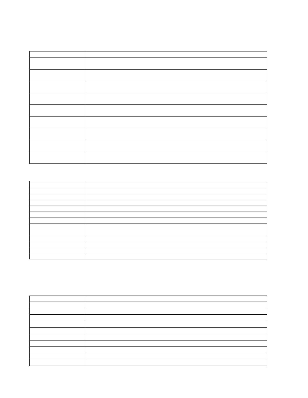
The Ronan X96S Density gage has 5 device variables:
Device Variable Value
D1 Density
D2 Density in alternate units
Proc Temp Process Temperature
Pressure Process Pressure
Head Temp Head Temperature
Density Gage Manual 012407
2
Page 7

Theory
Theory of Radiation Gaging
Radiation gages operate on the principle of radiation absorption and transmission.
A beam of gamma radiation is directed from the source holder, through the pipe (or vessel) and its process material, and onto the
surface of the detector.
Some amount of radiation is absorbed by the material through which it passes, and some of the radiation is transmitted to the
surface of the detector.
Process measurement is possible because the amount of radiation absorbed and transmitted is predictable.
The absorbed radiation is directly related to the density (or mass) of process in the pipe while the transmitted radiation is inversely
related to the density (or mass) of process in the pipe.
Therefore, an increased process density results in a decrease of transmitted radiation.
Since the radiation that's not being absorbed is being transmitted, the process density can be inferred by measuring the amount of
radiation reaching the detector at any point in time. The detector's output signal, in counts, also varies inversely to the process
density.
When the process is light (low density) the detector is exposed to a maximum amount of radiation which produces a HIGH output
of counts. When the process is heavy (high density) the process material "shields" the detector and prevents radiation from
reaching the detector, producing a LOW output of counts.
Ronan’s Density Monitor is used to replace the lab sampling process since the gage output, when accurately calibrated, will
correlate to the density values of process taken from samples near the gage location.
The X96S Microprocessor converts the detector signal to user's measurement units of SGU, percent solids, Baume H, Baume L,
API, or percent steam. The X96S Microprocessor is capable of simultaneously displaying density in two different sets of units.
These different representations of the density value are called density 1 and density 2.
The X96S displays the output measurement range in the selected user units. Channel 1 and Channel 2 can be set independently.
For both channels, the "zero" of the measurement range represents the lowest density of interest, while the "span" of the
measurement range represents the highest density of interest.
Reduction of the signal "noise" due to radiation statistics is handled in the stage of signal processing known as digital filtering.
Digital filtering is a form of statistical averaging used to smooth, or dampen, random radiation as well as process-related noise.
Increasing the digital filter’s “time constant” decreases signal noise.
Dynamic tracking permits the gage response to temporarily by-pass the digital filter. This is helpful in some processes where
sudden or drastic step changes in process must be observed in their true, or unfiltered, state.
Software also compensates for the decay of the radioactive source activity. On-going adjustments are made automatically for the
rate of decay, or source half-life.
Principles of Operation
The detector's raw output signal is processed through several stages of software in the X96S.
Some of the more significant stages of signal processing are:
• Units Conversion – conversion of density (SpG) into user-selected units
• Measurement Range – 4-20 mA output defined by the user-selected range in user-selected units.
Density Gage Manual 012407
3
Page 8

• Digital Filtering – signal smoothing to reduce statistical radiation noise
• Dynamic Tracking – quick gage response to quick process changes.
• Source Decay Compensation – automatic compensation for the radioisotope decay
• Calibration (Referencing) – calibration of gage to user process.
The Calibration (or Referencing) procedure relates detector output (in counts) to numeric values that accurately represent the actual
process density.
The density algorithm (or curve) used by the X96S software is an exponential function. That is, the relationship between the
detector output and the process density is mathematically expressed as:
Id = Ioe
-ut(d-do)
Where:
Id = detector signal with process density (d)
= detector signal with reference density (do) in pipe
Io
u = the absorption coefficient
t = pipe internal diameter
d = density usually expressed in SpG
d
= reference density
o
The "calibration constant" (1/ut) is used by the X96S software to calculate process density.
Density Gage Manual 012407
4
Page 9

Password
Notice:
To access the Programming Menu, the Password is 101010.
Step 1: Power Up – You should now be on the Status Screen.
Step 2: Press F3 to go back.
Step 3: Now enter the password. (All digits are set at 000000 at this point.)
Press to get the digit to be # one
Press 2 times (The third digit should be highlighted.)
Press to get the digit to be # one
Press 2 times (The fifth digit should be highlighted.)
Press to get the digit to be # one
Press F4 (enter)
Note: If the wrong password was entered, press F1 (ALL0) to set all the digits to the number 0 and
you can begin re-entering the password from the beginning. Pressing F2 (RST0) will set the
individual digit that is highlighted back to the number 0.
Note: For security reasons, each digit will always be displayed as an asterisk.
Density Gage Manual 012407
5
Page 10
Menus/Operation
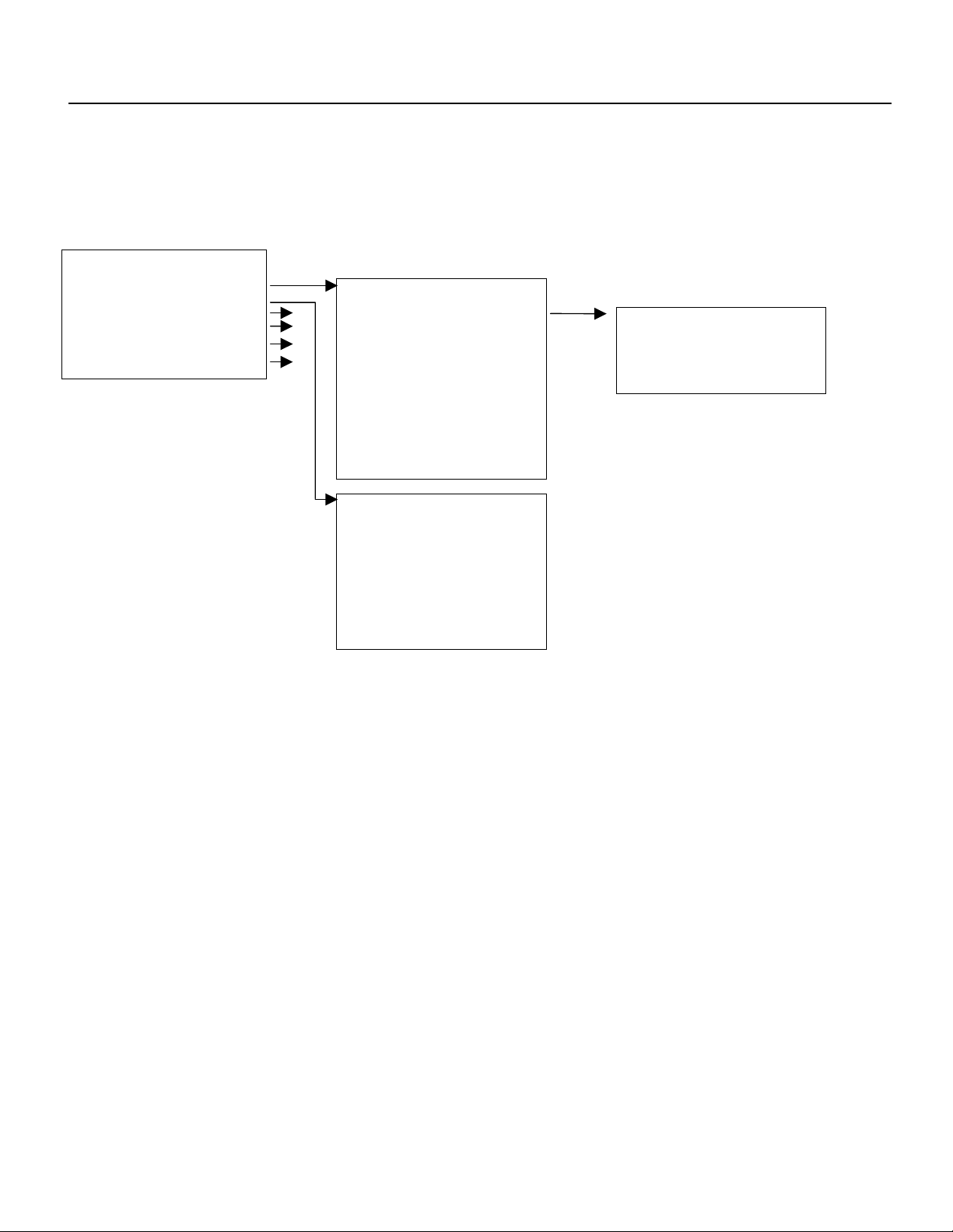
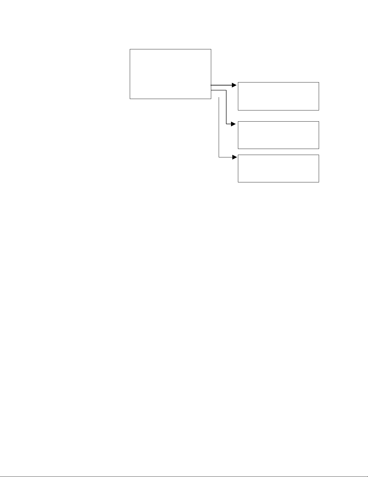
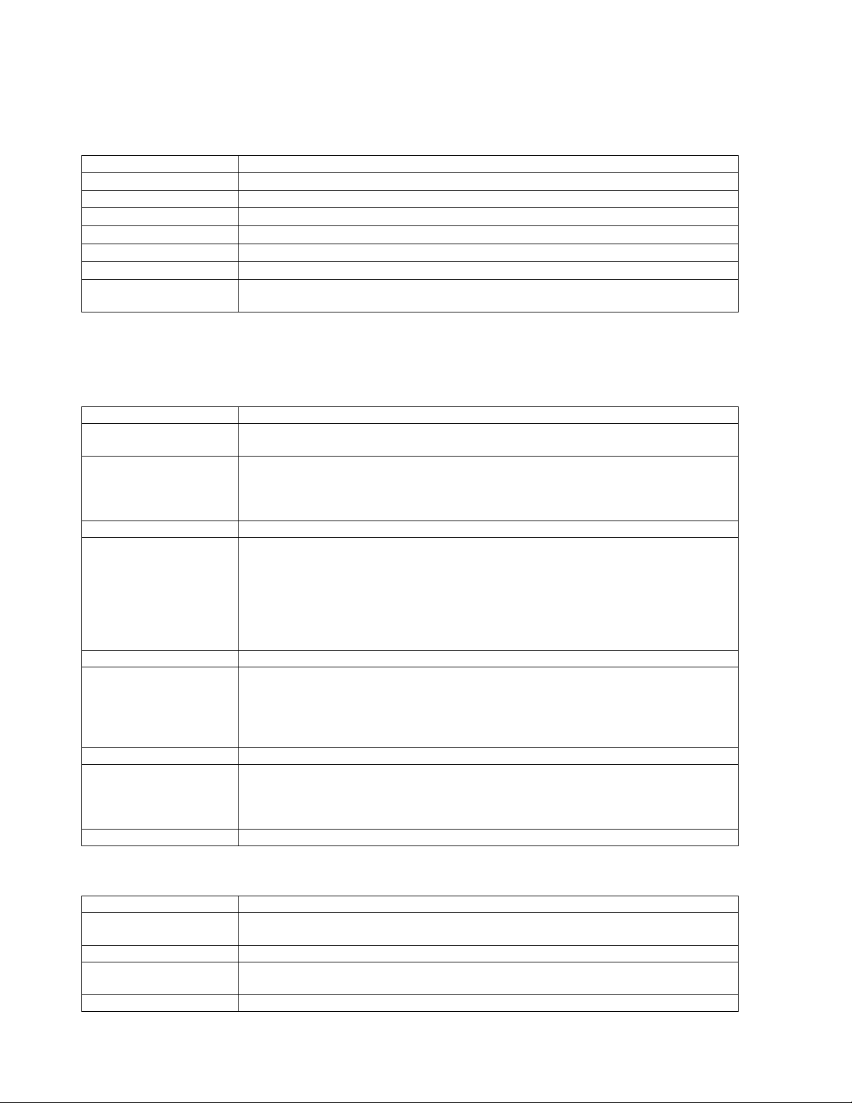
Menu Trees
The Ronan X96S Density Gage uses a tree structured menu system.
Ronan X96S - Density
Variables Variables
Status Display
Configuration 2 Variable Mapping Variable Mapping
Digital Outputs 4 PV [value units]
Digital Inputs 4 SV [value units] PV is [var mapped to PV]
Calibration 5 TV [value units] SV is [var mapped to SV]
Diagnostic QV [value units] TV is [var mapped to TV]
D1 [value units] QV is [var mapped to TV]
D2 [value units]
Proc Temp [value units]
Pressure [value units]
Head Temp [value units]
Raw Cnts [value]
Filt Cnts [value]
Status Display
Analog Bar [enable]
Line 1: [var]
Line 2: [var]
Line 3: [var]
Line 4: [var]
Line 5: [var]
Line 6: [var]
Line 7: [var]
Line 8: [var]
Figure 3-1 – Root, Variables and Displays Menus
Density Gage Manual 012407
6
Page 11
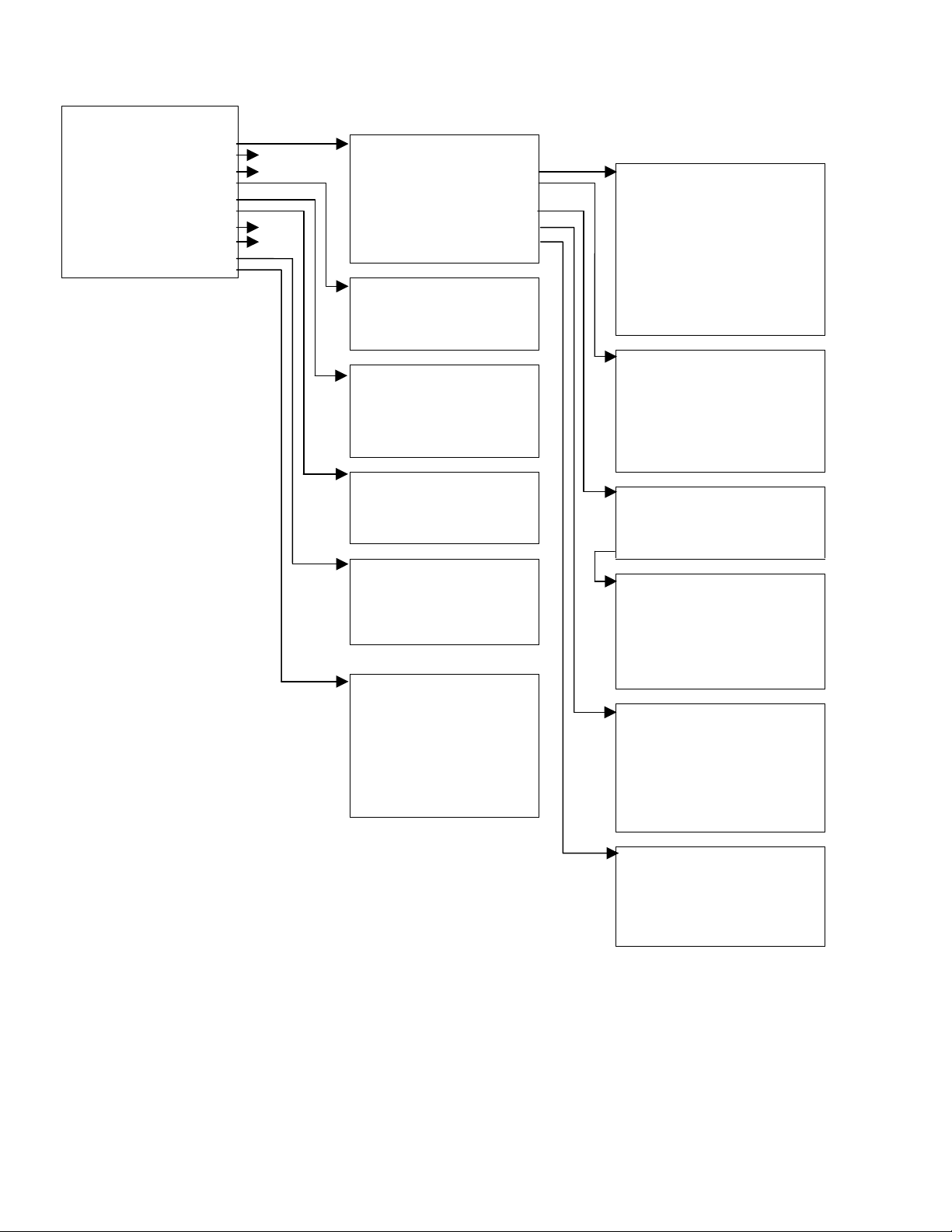
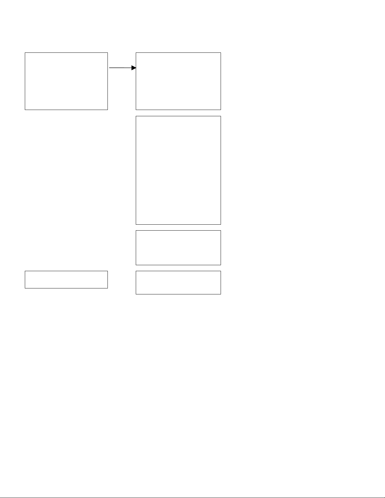
Configuration
Operation Operation
D1 Config 3
D2 Config 3 Filtering Filtering
Proc Temp Config Empty Clamp
Pressure Config Detector Fault Type RC
Head Temp Config Linearization Dyn Track [enable/disable]
Alarms 3 Temp Comp Sigma [value]
Hardware 3 Pressure Comp Fast TC [s]
HART Scan Time [ms] Fast Counter [value]
System Medium TC [s]
Proc Temp Config Slow Counter [value]
Temp Units [°C/F/R/Kelvin] Noise Filter [value]
Low Range [value] Monitor [track value]
High Range[value]
Pressure Config
Pressure Units
[psi;bar;g/Sqcm;kg/Sqcm;pa;kPa
;atm]
Low Range [value] Rcvry Time [seconds]
High Range [value] Min Counts [value]
Head Temp Config
Temp Units [°C/F/R/Kelvin]
Low Range [value] Linearize [enable/disable]
High Range [value] Clear Table
HART
Tag Name [name]
MultiDrop [addr] Table Entry # [number]
Univ Rev [rev] Entry Used [indicator]
Spec Rev [rev] Measured [value]
System Remove Entry
Slow TC [s]
Empty Clamp
Empty Clamp [enable/disable]
Off Time [seconds]
Max Counts [value]
Linearization
Config Linearize
Config Linearize
Actual [value]
Set Entry
Serial # [number] Temp Comp
Hardware Rev [rev]
Software Rev [rev] Temp Comp [enable/disable]
Date [date] Temp Units [units]
Hour (0-23) [hour] A Coeff [value]
Minute [min] B Coeff [value]
Password Enter Temp
Date/Time Format [sel]
Temp Auto Cap [enable/disable]
Last Ref. Temp [°F]
Pressure Comp
Pres Comp [enable/disable]
Pressure Units [units]
A Coeff [value]
Enter Pressure [value]
Pres Auto Cap [enable/disable]
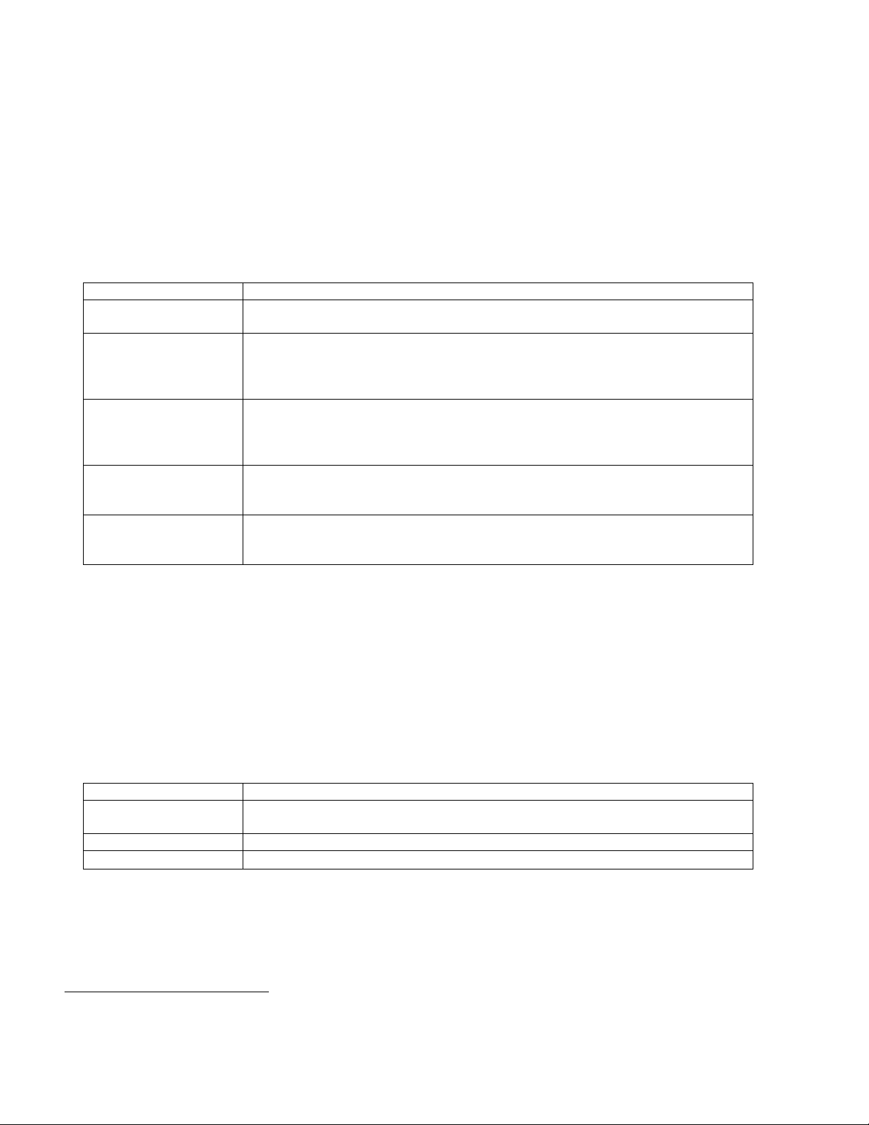
Figure 3-2 – Configuration Menus (1 of 3)
Density Gage Manual 012407
7
Page 12
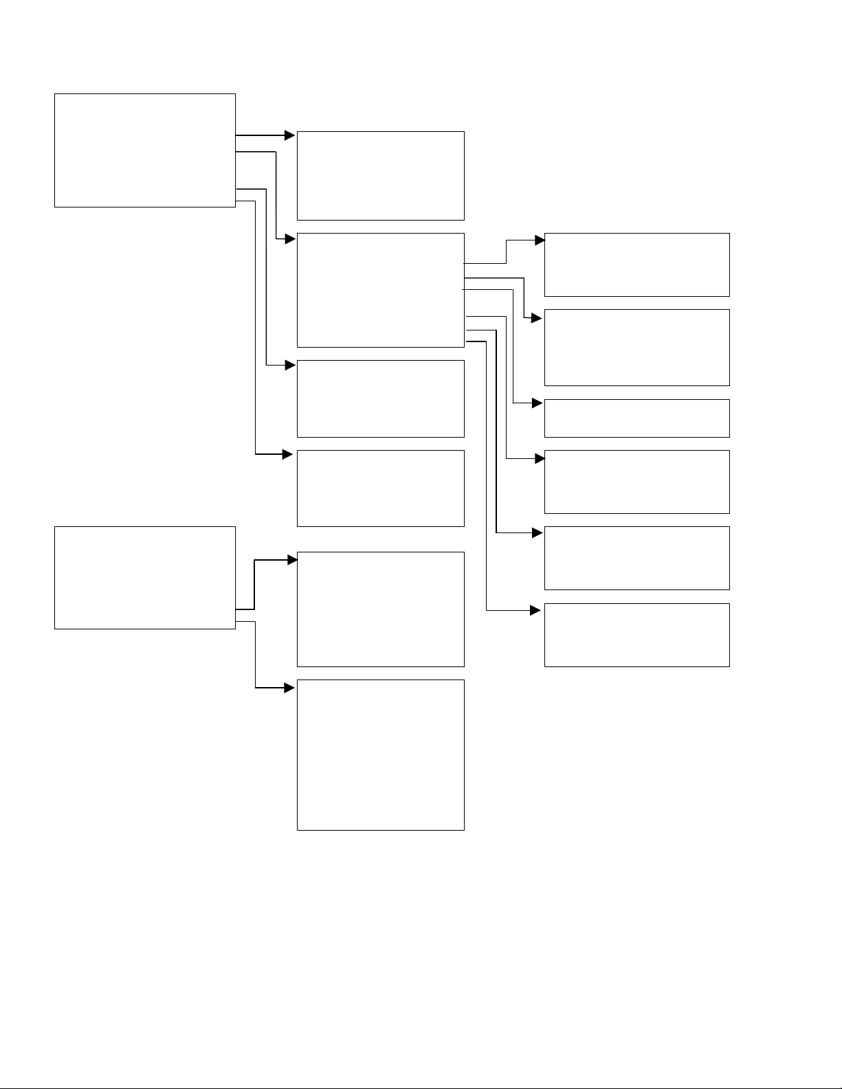
Configuration (Cont’d) Density 1 Config % Solids Variables
D1 Config D1 Units [units] Carrier [value]
D2 Config Low Range [value] Solids [value]
Alarms High Range [value]
Hardware % Solids Variables
% Acids Variables % Acids Variables
Density 2 Config Algorithm
Same Options as Density 1
D2 Units [units] Parameter B
Low Range [value] Parameter C
High Range [value]
% Solids Variables
% Acids Variables
Parameter A
Alarm 1 Alarm (number)
Alarm 2
Alarm 3 Source [variable]
Alarm 4 Alarm Type [variable]
Alarm 5 Setpoint [SGU]
Alarm 6 Setpoint 2 [SGU]
Alarm 7 Hysterisis [%]
Alarm 8
Alarm on 4-20 mA Alarm on 4-20mA
System Hardware System Hardware
Proc Temp [variable] CPU Card [type]
Source Type Slot 1 Details
Pressure Slot 2
Analog Out Config Slot 2 Details
HART Output X96S-20 Slot 3
Com1 Protocol Ronan Slot 3 Details
Alarms
None
Underrange
Overrange
Hardware Freeze
Slot 4
Slot 4 Details
Slot 5
Slot 5 Details
Slot 6
Slot 6 Details
Slot 7
Slot 7 Details
Slot 8
Slot 8 Details
Display X96-2000PL
Display Details
HART X96-2005PL
HART DB Details
Density Gage Manual 012407
Slot Details
Status
Serial Number
SW Major Rev
SW Minor Rev
HW Rev
Source Type
Source Type [type]
User Def Source
Next Reference[date]
Next Wipe Test
Next Shutter Test
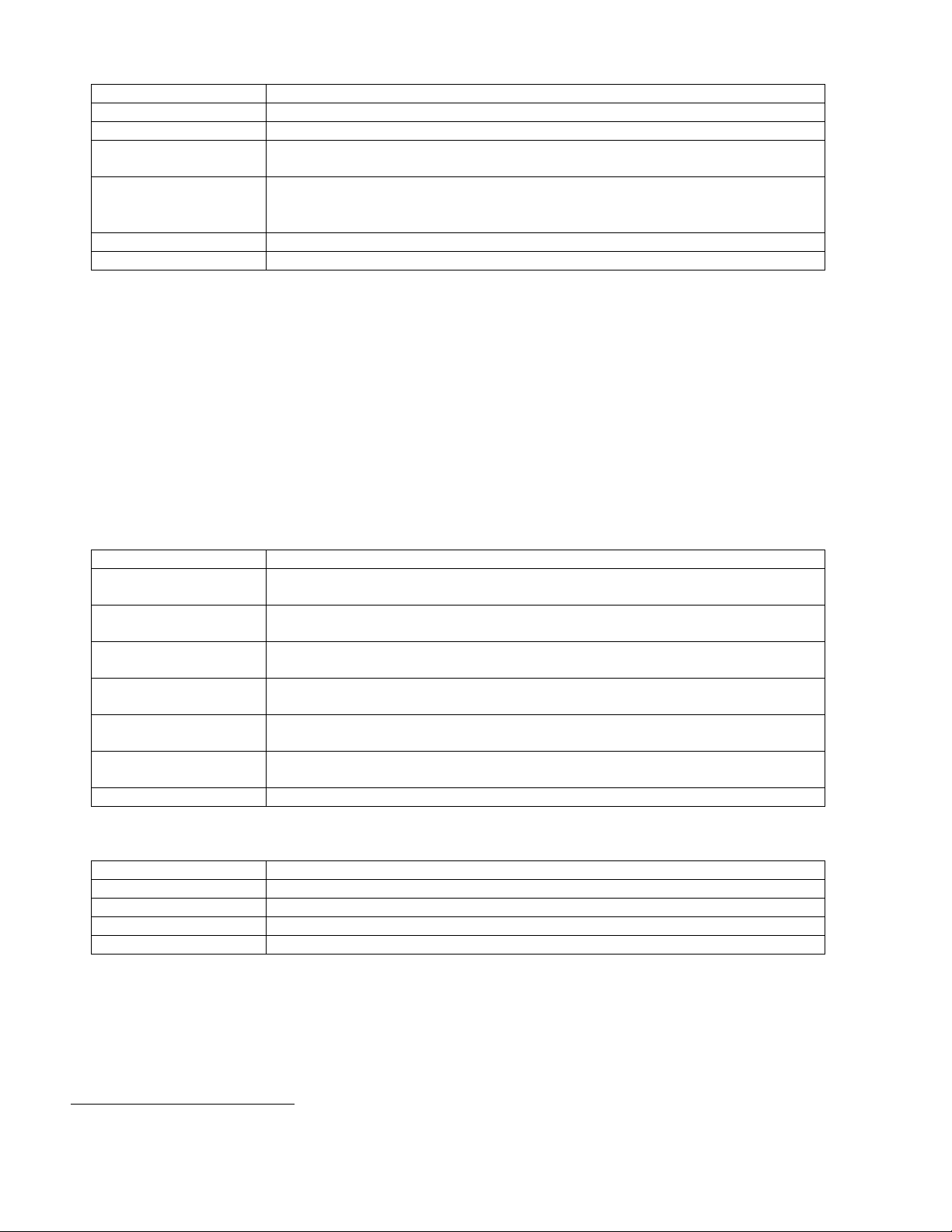
Figure 3-2 – Configuration Menus (2 of 3)
8
Page 13
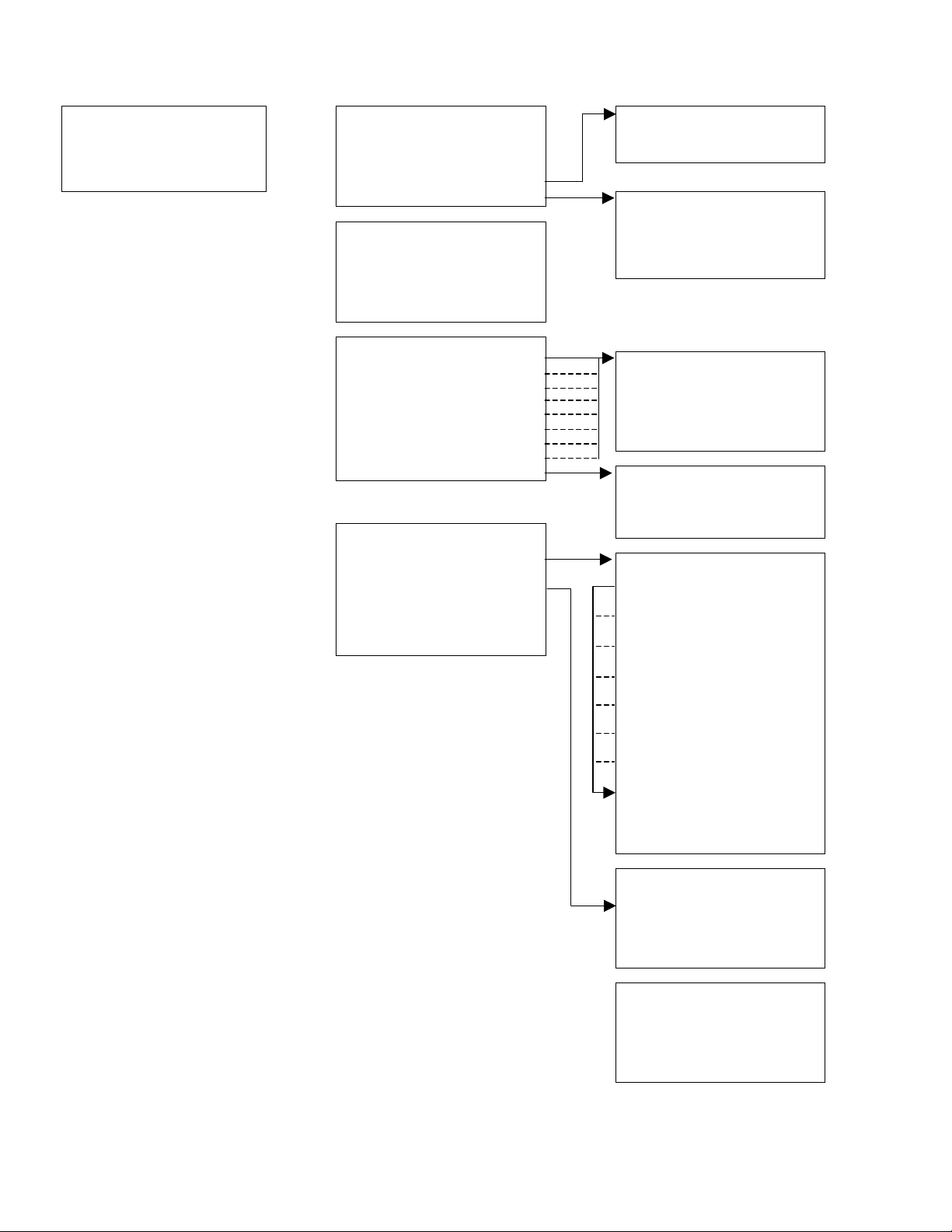
Configuration (Cont’d) Hardware (Cont’d)
Hardware (Cont’d) System Hardware
Proc Temp [variable]
Source Type
Pressure
Analog Out Config Analog Out Config
HART Output Loop 1 (PV) [variable]
Com1 Protocol Ronan Loop 2 (SV) [variable]
Figure 3-2 – Configuration Menus (3 of 3)
Loop 3 (TV) [variable]
Power Source [int/ext]
HART Output
None
X96S-2005
Ser. Port 1
Com1 Protocol
None
Hart
Ronan Setup
Density Gage Manual 012407
9
Page 14
Digital Outputs Output
Output [Relay 1-4/TTL 1-4] Relay 1
Select Sources [variable] Relay 2
Polarity [variable] Relay 3
Relay 4
TTL 1
TTL 2
TTL 3
TTL 4
Output [selected relay or TTL]
Alarm 1 [yes/no]
Alarm 2 [yes/no]
Alarm 3 [yes/no]
Alarm 4 [yes/no]
Alarm 5 [yes/no]
Alarm 6 [yes/no]
Alarm 7 [yes/no]
Alarm 8 [yes/no]
Auto Cal Ref [yes/no]
Auto Cal Err [yes/no]
Ref Prompt [yes/no]
Wipe Test [yes/no]
Shutter Test [yes/no]
Empty Clamp [yes/no]
Detector Flt [yes/no]
System Alarm [yes/no]
Select Sources
Polarity
No/Not Driven
NC/Driven
Open/Not Driven
Closed/Driven
Digital Inputs Input 1
Input 1 Use [not used/auto ref]
Polarity [high/low]
Figure 4-1– Digital Output and Digital Input Menus
Density Gage Manual 012407
10
Page 15
Calibration
State [state]
Ref Constants Ref Constants
Calibrate
Last Ref Date [date] Ref Mode [variable]
Last Ref Time [time] Calibr. Mode [variable]
Loop Config Ref Time [time]
Aux Loop Cfg Min Ref Cnts [counts]
Max Ref Cnts [counts]
Calibrate Low Reference
Low Reference Reference
High Calibrate Ref Density [value units]
Manual Entry Ref Cap [counts]
Clear Ref/Cal
Temp Ref High Calibrate
Pressure Ref
Auto Reference Calibrate
Loop Config Cal Cap [counts]
PV is [variable]
Loop test Manual Entry
Damping
D/A trim 1/uT [slope]
Aux Loop Config Temp Reference
SV is [variable] Temp Ref
Aux 1 Test Temp Cap Low [counts]
Aux 1 Trim Temp Cap High [counts]
TV is [variable]
Diagnostic Pressure Reference
Cal Density [value units]
1/uT [slope]
Raw Counts Ref/Cal Data Pressure Ref
Filt. Counts Pres Cap Low [counts]
Raw Dens. Last Ref Date [date] Pres Cap High [counts]
Current Ref Density 0
Ref/Cal Data Cal Density 2 Auto Reference
Alarms Ref Cap
Cal Cap Auto Ref [enable]
Last Ref Temp Ref Delay [s]
1/uT Auto Ref Density [SGU]
Alarms
Sys. Alarm
Empty Clamp
Det. Fault
AutoCal Ref
AutoCal Error
Ref. Prompt
Wipe Test
Shutter Test
Alarms
Output
Density Gage Manual 012407
Figure 3-5 – Calibration Menus
11
Page 16
Root Menu
The root menu is titled “Ronan X96S – Density”. It contains the following items:
ITEM FUNCTION
Variables
Displays
Configuration
Digital Outputs
Digital Inputs
Calibration
Diagnostic
Variables Menu
The menu titled “Variables” contains the following items:
ITEM FUNCTION
Variable Mapping
PV
SV
TV
QV
D1
D2
Proc Temp
Pressure
Head Temp
Raw Counts
Filt Counts
Selecting this takes the user to the Variables menu
Selecting this takes the user to the Displays menu
Selecting this takes the user to the Configuration menu
Selecting this takes the user to the Digital Outputs menu
Selecting this takes the user to the Digital Inputs menu
Selecting this takes the user to the Calibration menu
Selecting this takes the user to the Diagnostic menu
Selecting this takes the user to the Variable Mapping menu
Shows the current value of PV (the Primary Variable)
Shows the current value of SV (the Secondary Variable)
Shows the current value of TV (the Third Variable)
Shows the current value of QV (the Fourth Variable)
Shows the current value of D1 (the Density Variable)
Shows the current value of D2 (the Density Variable in alternate units)
Shows the current value of Proc Temp (the Process Temperature)
Shows the current value of Pressure (the Process Pressure)
Shows the current value of Head Temp (the Head Temperature)
Shows the current Raw Counts value from the detector
Shows the current Filtered Counts value from the detector
Variable Mapping Menu
The “Variable Mapping” menu allows the user to select the device variable to be mapped to PV, SV, TV, and QV. It contains
the following items:
ITEM FUNCTION
PV is
SV is
TV is
QV is
Each PV, SV, TV, and QV may each select one of the following:
SELECTION
D1
D2
Proc Temp
Pressure
Head Temp
Not Assigned
Density Gage Manual 012407
Shows the device variable assigned to PV and allows the user to change the selection
Shows the device variable assigned to SV and allows the user to change the selection
Shows the device variable assigned to TV and allows the user to change the selection
Shows the device variable assigned to QV and allows the user to change the selection
MEANING
Density represented in units that are used locally
Density represented in alternate units
Process temperature
Process pressure (if available)
Head temperature (if available)
Blank line
12
Page 17
Status Display Menu
The menu titled “Status Display” is used to configure the device status display. It contains the following items
ITEM FUNCTION
Analog Bar
Line 1:
Line 2:
Line 3:
Line 4:
Line 5:
Line 6:
Line 7:
Line 8:
Each line can select one of the following:
Shows the current state of the analog bar display (enabled or disabled) and allows the
user change the state.
Shows the data to be displayed on line 1 of the status display and allows the user to
change the selection
Shows the data to be displayed on line 2 of the status display and allows the user to
change the selection
Shows the data to be displayed on line 3 of the status display and allows the user to
change the selection
Shows the data to be displayed on line 4 of the status display and allows the user to
change the selection
Shows the data to be displayed on line 5 of the status display and allows the user to
change the selection
Shows the data to be displayed on line 6 of the status display and allows the user to
change the selection
Shows the data to be displayed on line 7 of the status display and allows the user to
change the selection
Shows the data to be displayed on line 8 of the status display and allows the user to
change the selection
SELECTION
D1
D2
Proc Temp
Pressure
Head Temp
4-20 mA
Raw Cnts
Filt. Cnts
Date & Time
Diagnostic
Not Assigned
MEANING
Density represented in units that are used locally
Density represented in alternate units,
Process temperature
Process pressure (if available)
Head temperature (if available)
4-20 mA output level
Raw counts (from scintillation detector) or raw analog measurement (from ionization
detector
Filtered counts (from scintillation detector) or (from ionization detector)
Current date and time
Selecting this takes the user to the Diagnostic Menu
Blank line
Configuration Menu
The Configuration menu is used to access area configuration menus. It contains the following items:
ITEM FUNCTION
Operation
D1 Config
D2 Config
Proc Temp Config
Pressure Config
Head Temp Config
Alarms
Hardware
HART
System
Selecting this takes the user to the Operation menu
Selecting this takes the user to the D1 Config menu
Selecting this takes the user to the D2 Config menu
Selecting this takes the user to the Proc Temp Config menu
Selecting this takes the user to the Pressure Config menu
Selecting this takes the user to the Head Temp Config menu
Selecting this takes the user to the Alarm menu
Selecting this takes the user to the Hardware menu
Selecting this takes the user to the HART menu
Selecting this takes the user to the System menu
Density Gage Manual 012407
13
Page 18
Operation Menu
The Operation menu is used to access the menus and variables that control the processing of the density data. It contains the
following items:
ITEM FUNCTION
Filtering
Empty Clamp
Detector Fault
Linearization
Temp Comp
Pressure Comp
Scan Time
Selecting this takes the user to the Filtering menu
Selecting this takes the user to the Empty Clamp menu
Selecting this takes the user to the Detector Fault menu
Selecting this takes the user to the Linearization menu
Selecting this takes the user to the Temp Comp menu
Selecting this takes the user to the Pressure Comp menu
Shows the amount of time to accumulate each density sample and allows the user
change the time value.
Filtering Menu
The Filtering menu is used to configure the parameters associated with the mold level measurement filter, utilizing the
standard scan rate. It contains the following items:
ITEM FUNCTION
Dyn Track
Sigma
Fast TC
Fast Counter
Medium TC
Slow Counter
Slow TC
Noise Filter
Monitor
Shows the current state of the dynamic tracking filter (enabled or disabled) and allows
the user to change the state
Shows the (sigma) multiplier used to determine maximum number of raw count
variation (for scintillation) or raw analog value (for ion chamber) that the input can
vary from the current filtered counts before changing to the dynamic filter. Sigma is
the square root of the current filtered counts. Also allows user to change this number.
Fast Time Constant value to be used when the Fast Counter reaches zero
Shows the fast count down counter value. If gage has been in dynamic tracking long
enough to be using Medium filter and the raw counts continued to exceed the sigma
value, the fast counter value is decreased each consecutive scan. The Fast counter
value resets and returns back to the original value if the raw counts do not continue to
exceed the sigma value. Once the Fast TC is triggered, it will continue to be used until
the counts are within the sigma value for the Fast counter number of times
consecutively. Also allows user to change this number
Medium Time Constant value to be used when the Slow Counter reaches zero
Shows the slow count down counter value. If gage is in dynamic tracking, and the raw
counts continue to exceed the sigma value, the slow counter value is decreased each
consecutive scan. The Slow counter value resets and returns back to the original value
if the raw counts do not continue to exceed the sigma value. Also allows user to
change this number
Slow Time Constant value to be used if the Slow Counter has not reached zero
Shows the maximum number of potentially erroneous measurements in a row to
bridge before deciding that a step change has occurred in the mold level value. Also
allows user to change this number. Erroneous measurement is defined when the raw
signal is 4 times the pre-selected sigma multiplier
Shows the current state of the filtering mechanism
Monitor (filter state) one of the following:
ITEM
ERROR
FILL
TRACK
REFILL
Density Gage Manual 012407
MEANING
Filter is not initialized (this state should not occur during normal operation of the
X96S Density Gage)
The walking average buffer is filling
The walking average buffer is filled and the filter is tracking changes in the density
value
A step change has occurred and the walking average buffer is refilling
14
Page 19
Empty Clamp Menu
The X96S uses a mechanism called empty clamp to protect detectors (particular scintillation detectors) from saturation conditions.
i.e.: Material being processed is lower than detector range, causing too much radiation to reach the detector, possibly damaging
the electronics. The Min Counts and the Max Counts parameters set the threshold (in raw counts
2
) for activation of the empty
clamp function. These Count values should be set above (Max Counts) the Reference Counts, and below (Min Counts) the
Calibrate Counts, and beyond your normal measurement range.
The Empty Clamp menu is used to configure the parameters associated with the mechanism that shuts off power to the detector
if the detector receives more radiation than it is capable of measuring. It contains the following items:
ITEM FUNCTION
Empty Clamp
Shows the current state of the empty clamp mechanism (enabled or disabled) and
allows the user change the state.
Off Time
Shows and allows the user to change the number of seconds that power to the detector
be shut off when the empty clamp mechanism activates before turning the detector on
to see if the radiation level has dropped to a value that the detector is capable of
measuring. Typical value ranges from 15 to 30 minutes.
Rcvry Time
Shows and allows the user to change the number of seconds that power will be applied
to the detector when the empty clamp mechanism has activated to see if the radiation
level has dropped to a value that the detector is capable of measuring. Typical value
here is 30 seconds.
Min Counts
Shows and allows the user to change the number minimum number of counts that are
used to determine that the detector is saturated (exposed to more radiation than it is
capable of measuring).
Max Counts
Shows and allows the user to change the number maximum number of counts that are
used to determine that the detector is exposed to more radiation than it is capable of
measuring.
Detector Fault Menu
The Detector Fault menu is used to configure a window in which the detector counts must fall within, in order to complete a
reference/calibration.
Linearization Menu
The X96S is capable of performing a multi-point linearization of the density data when required by an application. The
linearization table contains ten entries, numbered 1 through 10. Each entry consists of a measured value, an actual value, and a flag
that indicates if the entry is used
The Linearization menu is used to control the linearization mechanism. It contains the following items:
ITEM FUNCTION
Linearize
Clear Table
Config Linearize
Config Linearize Menu
The Config Linearize menu is used to configure the parameters associated with linearization of the measured data. It contains
the following items:
2
The threshold is in raw counts since the overload is a function of the radiation effect on the detector and not related to any
corrected or converted data.
3
Not all of the entries need to be used and the entries do not need to be used in any particular order.
3
.
Shows the current state of the Linearization mechanism (enabled or disabled) and
allows the user change the state.
This invokes a method that clears all entries in the linearization table
Selecting this takes the user to the Config Linearize menu
Density Gage Manual 012407
15
Page 20
ITEM FUNCTION
Table Entry #
Entry Used
Measured
Shows and allows the user to select an entry in the linearization table
Shows if the entry is used or not.
Shows and allows the user to set the measured value associated with this linearization
table entry. This is a value calculated by the X96S.
Actual
Shows and allows the user to set the actual value associated with this linearization
table entry. This value is the result of a lab sample, and compares to the Measured
value above.
Set Entry
Remove Entry
This invokes a method that sets a table entry
This invokes a method that removes a table entry
Temp Comp Menu
Temperature compensation in the X96s is calculated as a quadratic function4. If temperature compensation is to be used, the
process temperature can be captured automatically for you during Referencing by enabling Temp Auto Cap. If you choose to
enter the temperature manually, the entered value should be the temperature of the process material during the Referencing
function.
Process temperature is typically read via platinum or nickel, 2 or 3-wire RTD attached to the X96S. In these cases, the X96S needs
no temperature calibration. You can optionally feed a 0-10volt or 4-20mA signal into the X96S from another source that
represents the range of temperature for your process. In this case, you will need to perform a Temp Ref to set the range of
measurement. You will also need to define the type of temperature device you are using in the Hardware Menu, Proc Temp
menus.
The Temp Comp menu is used to control the temperature compensation mechanism
ITEM FUNCTION
Temp Comp
Shows the current state of the temperature compensation mechanism (enabled or
disabled) and allows the user change the state.
Temp Units
Shows and allows the user to set the temperature units used to by the temperature
compensation mechanism.
A Coeff
Shows and allows the user to set the “A” coefficient that relates temperature to
changes in density.
B Coeff
Shows and allows the user to set the “B” coefficient that relates temperature to
changes in density.
Enter Temp
Shows and allows the user to set the process temperature at the time that the gage was
Referenced (if Auto Cap was ‘enabled’ during Referencing).
Temp Auto Cap
This invokes a method that captures the process temperature automatically during gage
Referencing.
Last Ref Temp
Shows the temperature of the process at the time the last reference was completed
Temp Units is one of the following:
ITEM MEANING
degC
degF
degR
Kelvin
degrees Celsius
degrees Fahrenheit
degrees Rankine
degrees Kelvin
4
. It contains the following items:
Pressure Comp Menu
Pressure compensation is calculated based on the pressure input. The pressure-input range is selected in the Pressure Config
Menu, Hardware Menu, and the Pressure Reference Menu.
The Pressure Comp menu is used to control pressure compensation mechanism
4
compensated density = uncompensated density + (A Coeff * temperature delta) + (B Coeff * temperature delta2)
5
compensated density = uncompensated density + (A Coeff * pressure delta)
Density Gage Manual 012407
16
5
. It contains the following items:
Page 21
ITEM FUNCTION
Pres Comp
Pressure Units
A Coeff
Enter Pressure
Pres Auto Cap
Scan Time
Pressure Units is one of the following:
ITEM MEANING
PSI
Bar
G/Sqcm
Kg/Sqcm
Pa
KPa
atm
Shows the current state of the pressure compensation mechanism (enabled or disabled)
and allows the user change the state
Shows and allows the user to se, the pressure units used to by the pressure
compensation mechanism
Shows and allows the user to set the “A” coefficient that relates pressure to changes in
density
Shows, and allows the user to set, the process pressure at the time that the gage was
Referenced (if Auto Cap was ‘enabled’ during Referencing).
This invokes a method that captures the process temperature automatically during gage
Referencing
Shows the amount of time to accumulate each density sample and allows the user to
change the time value
Pounds per square inch
Bar
Grams/square centimeter
Kilograms/square centimeter
Pascal
Kilopascal
Atmosphere
D1 Config Menu
The D1 Config menu is used to configure the parameters associated with the density measurement. It contains the following
items:
ITEM FUNCTION
D1 Units
D1 Low Range
D1 High Range
% Solids
Variables
% Acids
Variables
D1 Units is one of the following:
ITEM MEANING
SGU
degTwad
degBrix
degBaum_hv
degBaum_lt
degAPI
Percent_sol_wt
degBall
percent_StmQual
% Acids
Shows and allows the user to set the density units used
Shows and allows the user to set the density value to be mapped to 4ma on the current
loop output, if D1 is selected to control that current loop.
Shows and allows the user to set the density value to be mapped to20ma on the current
loop output, if D1 is selected to control that current loop.
Selecting this takes the user to the % Solids Variables menu
Selecting this takes the user to the % Acids Variables menu
specific gravity
degrees twaddle
degrees brix
degrees baume heavy
degrees baume light
degrees API
percent solids by weight
degrees balling
percent steam quality
percent acids
Density Gage Manual 012407
17
Page 22

% Solids Variables Menu
The % Solids Variables menu is used to configure the parameters associated with the percent of solids measurement. It
contains the following items:
ITEM FUNCTION
Carrier
Solids
Shows and allows the user to set the density of the carrier
Shows and allows the user to set the density of the solids
% Acids Variables Menu
The % Acids Variables menu is used to configure the parameters associated with the percent of acids measurement. It
contains the following items:
ITEM FUNCTION
Algorithm
Parameter A
Parameter B
Parameter C
Allows the user to select the desired algorithm
Allows the user to adjust the Parameter A value
Allows the user to adjust the Parameter B value
Allows the user to adjust the Parameter C value
Algorithm Menu
The Algorithm menu allows the user to select the calculation associated with the percent of acids measurement.
ITEM MEANING
Linear
Log
Quadratic pos/neg
None
A (Y) + B
In (Y) + A
A (Y)^2 + B (Y) + C
Not used
D2 Config Menu
The D2 Config menu is used to configure the parameters associated with the alternate representation of the density
measurement. It contains the following items:
ITEM FUNCTION
D2 Units
D2 Low Range
D2 High Range
% Solids
Variables
% Acids
Variables
D2 Units is one of the following:
ITEMS MEANING
SGU
degTwad
degBrix
degBaum_hv
degBaum_lt
degAPI
Percent_sol_wt
Shows and allows the user to set the density units used for the alternate representation
of the density measurement
Shows and allows the user to set the density value to be mapped to 4ma on the current
loop output, if D2 is selected to control that current loop.
Shows and allows the user to set the density value to be mapped to20ma on the current
loop output, if D2 is selected to control that current loop.
Selecting this takes the user to the % Solids Variables menu
Selecting this takes the user to the % Acids Variables menu
specific gravity
degrees twaddle
degrees brix
degrees baume heavy
degrees baume light
degrees API
percent solids by weight
Density Gage Manual 012407
18
Page 23

ITEMS MEANING
degBall
Percent_StmQual
Percent Acids
degrees balling
percent steam quality
percent acids
% Solids Variables Menu
The % Solids Variables menu is used to configure the parameters associated with the percent of solids measurement. It
contains the following items:
ITEM FUNCTION
Carrier
Solids
Shows and allows the user to set the density of the carrier
Shows and allows the user to set the density of the solids
% Acids Variables Menu
The % Acids Variables menu is used to configure the parameters associated with the percent of acids measurement. It
contains the following items:
ITEM
Algorithm
Parameter A
Parameter B
Parameter C
FUNCTION
Allows the user to select the desired algorithm
Allows the user to adjust the Parameter A value
Allows the user to adjust the Parameter B value
Allows the user to adjust the Parameter C value
Algorithm Menu
The Algorithm menu allows the user to select the calculation associated with the percent of acids measurement.
ITEM MEANING
Linear
Log
Quadratic
positive/negative
None
A (Y) + B
In (Y) + A
A (Y)^2 + B (Y) + C
Not used
Proc Temp Config Menu
The Proc Temp Config menu is used to configure the parameters associated with the process temperature measurement. It
contains the following items:
ITEM FUNCTION
Temp Units
Low Range
High Range
Shows and allows the user to set the units to be used for process temperature
Shows and allows the user to set the temperature value to be mapped to 4ma on the
current loop output, if process temperature is selected to control that current loop.
Shows and allows the user to set the temperature value to be mapped to20ma on the
current loop output, if process temperature is selected to control that current loop.
Temp Units is one of the following:
ITEM MEANING
degC
degF
degR
Kelvin
Density Gage Manual 012407
degrees Celsius
degrees Fahrenheit
degrees Rankine
degrees Kelvin
19
Page 24

Pressure Config Menu
The Pressure Config menu is used to configure the parameters associated with the process pressure measurement. It contains
the following items:
ITEM FUNCTION
Pressure Units
Low Range
High Range
Pressure Units is one of the following:
ITEM MEANING
PSI
Bar
G/Sqcm
Kg/Sqcm
Pa
KPa
atm
Shows and allows the user to set the units to be used for process pressure
Shows and allows the user to set the pressure value to be mapped to 4ma on the
current loop output, if process pressure is selected to control that current loop.
Shows and allows the user to set the pressure value to be mapped to20ma on the
current loop output, if process pressure is selected to control that current loop.
Pounds per square inch
Bar
Grams/square centimeter
Kilograms/square centimeter
Pascal
Kilopascal
Atmosphere
Head Temp Config Menu
The Head Temp Config menu is used to configure the parameters associated with the detector electronics temperature
measurement. It contains the following items:
ITEM FUNCTION
Temp Units
Low Range
High Range
Shows and allows the user to set the units to be used for head temperature
Shows and allows the user to set the temperature value to be mapped to 4ma on the
current loop output, if head temperature is selected to control that current loop.
Shows and allows the user to set the temperature value to be mapped to20ma on the
current loop output, if head temperature is selected to control that current loop.
Alarms
The Alarms menu is used to configure the parameters associated with the analog alarms. This applies to alarms 1-8 as well as the
4-20mA alarm.
ITEM FUNCTION
Alarm Type
Setpoint
Setpoint2
Hysterisis
Alarm Type is one of the following:
ITEM
None
Low
High
Range
Shows and allows the user to set the alarm type
Shows and allows the user to set the alarm set point
Shows and allows the user to set the second alarm set point
Shows and allows the user to set the alarm hysterisis percent
MEANING
Alarm not yet set
Alarm when the source is equal to or lower than Setpoint
Alarm when the source is equal to or higher than Setpoint
Alarm when the source is equal to or lower than Setpoint OR the source is equal
to or higher than Setpoint2
6
6
The second alarm set point is only used when the alarm type is range.
Density Gage Manual 012407
20
Page 25

Hardware Menu
The Hardware menu is used to define the type of hardware used to provide measurements and radiation. It contains the
following items:
ITEM FUNCTION
System Hardware
Proc Temp
Source Type
Pressure
Analog Out Config
HART Output
Com1 Protocol
The System Hardware menu takes the user to a list of the hardware modules in the system and the status of these modules:
ITEM FUNCTION
CPU Card
CPU Status
DIO Card
DIO Status
Slot 3 Card
Slot 3 Status
Slot 4 Card
Slot 4 Status
Slot 5 Card
Slot 5 Status
Slot 6 Card
Slot 6 Status
Slot 7 Card
Slot 7 Status
Slot 8 Card
Slot 8 Status
Display X96-2002
Display Status
HART X96-2005
HART Status
Shows the user the list of hardware modules in the system and the status of these
modules
Shows and allows the user to set the type of device used to read process temperature
Selecting this item takes the user to the Source Type menu
Shows and allows the user to set the type of device used to read process pressure
Shows and allows the user to set the source of power as internal or external
Shows and allows the user to adjust the HART output functions
Shows and allows the user to adjust the Com1 Protocols [None/Hart/Ronan Setup]
Shows the type of CPU card installed (in slot 1)
Status of the CPU card
Shows the type of DIO (Digital Input/Output) card installed (in slot 2)
Status of the DIO card
Shows the type of card (if any) installed in slot 3
If a card is installed in slot 3, shows the status of the card, else shows None
Shows the type of card (if any) installed in slot 4
If a card is installed in slot 4, shows the status of the card, else shows None
Shows the type of card (if any) installed in slot 5
If a card is installed in slot 5, shows the status of the card, else shows None
Shows the type of card (if any) installed in slot 6
If a card is installed in slot 6, shows the status of the card, else shows None
Shows the type of card (if any) installed in slot 7
If a card is installed in slot 7, shows the status of the card, else shows None
Shows the type of card (if any) installed in slot 8
If a card is installed in slot 8, shows the status of the card, else shows None
Shows the type of display module (if any attached)
Shows the status of the display module if attached, or else shows None
Shows the type of the HART interface (if any) present
Shows the status of the HART interface, if the interface is present, else shows None
Proc Temp is one of the following:
ITEM
None
pt100_a_385
pt100_a_392
ni120
0-10 volts
4-20 ma
Density Gage Manual 012407
MEANING
No temperature measurement device configured
Platinum RTD with an alpha of 885 (commonly used in USA)
Platinum RTD with an alpha of 892 (commonly used in Europe)
Nickel RTD
Temperature measurement device that provides a 0 to 10 volt signal
Temperature measurement device that provides a 4-20 ma signal
21
Page 26

Source Type Menu
The Source Type menu is used to define the type of radiation source used. It contains the following items:
ITEM FUNCTION
Source Type
Usr Def Source
Next Reference
Next Wipe Test
Next Shutter
Test
Source Type is one of the following:
Shows and allows the user to set the source type
Selecting this takes the user to the Usr Def Source menu
Shows the date of when the next Reference should be completed
Shows the date of when the next Wipe Test should be completed
Shows the date of when the next Shutter Test should be completed
ITEM
Unknown
co_60
cs_137
am_241
Usr Def
MEANING
Source type not known
Cobalt 60
Cesium 137
Americium 241
Any source type other than the ones listed above OR a source of the nominal type
listed above with a different half-life
Usr Def Source Menu
The Usr Def Source menu is used to define the type of radiation source used. It contains the following items:
ITEM FUNCTION
Name
Half Life
Pressure is one of the following:
ITEM
None
0-10 volts
4-20 ma
Shows, and allows the user to set, the source type name
Shows, and allows the user to set, the source half life
MEANING
No pressure measurement device configured
Pressure measurement device that provides a 0 to 10 volt signal
Pressure measurement device that provides a 4-20 ma signal
Analog Out Config
The analog Out Config menu is used to set where the source of power is. It contains the following items:
ITEM FUNCTION
Loop 1
Loop 2
Loop 3
Power Source
Loops 1-3 contain the following selections:
ITEM FUNCTION
X96S-2005
X96S-2004, chan 1
X96S-2004, chan 2
None
Density Gage Manual 012407
Shows and allows the user to assign a source to Loop 1
Shows and allows the user to assign a source to Loop2
Shows and allows the user to assign a source to Loop 3
Shows and allows the user to set whether the source of power is internal or
external, to power the AO modules outputs
Selecting this will assign the HART card to the desired loop
Selecting this will allow the user to assign channel 1 to the desired loop
Selecting this will allow the user to assign channel 2 to the desired loop
No card selected
22
Page 27

HART Output Menu
The HART Output menu is used to define the type of HART Output desired.
ITEM FUNCTION
X96S-2005
Serial Port 1
None
Selecting this will assign the HART card
Selecting this will allow the user to use Serial Port 1
No HART Output desired
Com1 Protocol Menu
Com1 Protocol contains the following items:
ITEM MEANING
HART HART protocol
Ronan Setup Ronan Setup protocol
HART Menu
The Hardware menu is used to provide information about the HART interface. It contains the following items:
ITEM FUNCTION
Tag Name
MultiDrop
Univ Rev
Spec Rev
Shows and allows the user to set the device tag name
Shows and allows the user to set the multi-drop address for a device (or 0 if the device
is not used on a multi-drop loop)
Shows the HART universal command revision to which this device is conferment
Shows the HART specification revision to which this device is conferment
System Menu
The System menu is used to provide information about the X96S. It contains the following items:
ITEM FUNCTION
Serial #
Hardware Rev
Software Rev
Date
Hour (0-23)
Minute
Password
Date/Time Format
Date/Time Format is one of the following:
ITEM
mm/dd/yy hh:mm:ss
mm/dd/yyyy hh:mm:ss
mm/dd/yy hh:mm:ss
am/pm
dd-mm-yy hh:mm:ss
dd-mm-yyyy hh:mm:ss
dd/mm/yy hh:mm:ss
dd/mm/yyyy hh:mm:ss
Shows the device serial number
Shows the device hardware revision
Shows the device software revision
Shows and allows the user to set the date
Shows and allows the user to set the hour
Shows and allows the user to set the minute
Shows and allows the user to set a password from the main display to allow access to
all menus
Shows and allows the user to set the date/time format used on the status display
MEANING
North American date and 24 hour time
North American Y2K date and 24 hour time,
North American date and 12 hour time with am/pm indication
European date and 24 hour time,
European Y2K date and 24 hour time
European date and 24 hour time
European Y2K date and 24 hour time
Density Gage Manual 012407
23
Page 28

Digital Outputs Menu
This menu is used to view and configure the digital outputs. It contains the following items:
ITEM FUNCTION
Output
Select Sources
Polarity
Select Sources has the following option to assign:
ITEM FUNCTION
Alarm 1 [yes/no]
Alarm 2 [yes/no]
Alarm 3 [yes/no]
Alarm 4 [yes/no]
Alarm 5 [yes/no]
Alarm 6 [yes/no]
Alarm 7 [yes/no]
Alarm 8 [yes/no]
Auto Cal Ref [yes/no]
Auto Cal Err [yes/no]
Ref Prompt [yes/no]
Wipe Test [yes/no]
Shutter Test [yes/no]
Empty Clamp [yes/no]
Detector Flt [yes/no]
System Alarm [yes/no]
Shows and allows the user to select and configure a specific digital output
TTL 1-4)
Selecting this allows the user to assign an array sources to the above digital output
Shows and allows the user to set the above digital output
Allows the user to assign Alarm 1 to the selected digital output
Allows the user to assign Alarm 2 to the selected digital output
Allows the user to assign Alarm 3 to the selected digital output
Allows the user to assign Alarm 4 to the selected digital output
Allows the user to assign Alarm 5 to the selected digital output
Allows the user to assign Alarm 6 to the selected digital output
Allows the user to assign Alarm 7 to the selected digital output
Allows the user to assign Alarm 8 to the selected digital output
Allows the user to assign Auto Cal Ref to the selected digital output
Allows the user to assign Auto Cal Err to the selected digital output
Allows the user to assign Ref Prompt to the selected digital output
Allows the user to assign Wipe Test to the selected digital output
Allows the user to assign Shutter Test to the selected digital output
Allows the user to assign Empty Clamp to the selected digital output
Allows the user to assign Detector Flt to the selected digital output
Allows the user to assign System Alarm to the selected digital output
(Relay 1-4 or
Polarity has the following option to assign:
ITEM FUNCTION
NO/Not Driven
NC/Driven
Open/Not Driven
Allows the user to configure the selected digital output as non-fail safe mode
Allows the user to configure the selected digital output as fail safe mode
Allows the user to force the selected digital output open or not driven (relay deenergized) or driven (TTL not driven) regardless of the state of the source
Closed/Driven
Allows the user to force the selected digital output closed (relay energized) or driven
(TTL driven) regardless of the state of the source
Density Gage Manual 012407
24
Page 29

Relay and TTL Menus
The Relay and TTL menus are used to configure the X96S Relay Outputs and the 4 TTL Outputs. The Relay and TTL menus
show the settings of the corresponding 4 Relay Outputs and 4 TTL Outputs, allowing the characteristics of the outputs to be
changed. Each menu contains the following items:
Output (Cont’d.)
ITEM FUNCTION
Relay 1
Relay 2
Relay 3
Relay 4
TTL 1
TTL 2
TTL 3
TTL 4
Selecting this takes the user to the Relay 1 menu
Selecting this takes the user to the Relay 2 menu
Selecting this takes the user to the Relay 3 menu
Selecting this takes the user to the Relay 4 menu
Selecting this item takes the user to the TTL 1 menu
Selecting this takes the user to the TTL 2 menu
Selecting this takes the user to the TTL 3 menu
Selecting this takes the user to the TTL 4 menu
Digital Inputs Menu
This menu is used to view and configure the digital input(s). It contains the following item:
ITEM FUNCTION
Input 1
Selecting this takes the user to the Input 1 menu
Input 1 Menu
The Input 1 menus (is used to configure the X96S digital input. It contains the following items:
ITEM FUNCTION
Use
Polarity
Use is one of the following:
ITEM
Not Used
Auto Ref
Polarity is one of the following:
ITEM
Low
High
Shows, and allows the user to set, the use of the digital input
Shows, and allows the user to set, the active state of the digital input
MEANING
This digital input is not used
A “true” on this digital input indicates that the X96S should perform the auto reference
procedure
MEANING
A “true” is represented by a low signal on the digital input
A “true” is represented by a high signal on the digital input
Density Gage Manual 012407
25
Page 30

Calibration Menu
This menu is used to view and control the calibration of the X96S Density Gage. It contains the following items:
ITEM FUNCTION
State
Ref Constants
Calibrate
Last Ref Date
Last Ref Time
Loop Config
Aux Loop Cfg
State is one of the following:
Shows the state of the density configuration process
Selecting this takes the user to the Ref Constants menu
Selecting this takes the user to the Calibrate menu
Shows the date on which the gage was most recently Low Referenced.
Shows the time on which the gage was most recently Low Referenced
Selecting this takes the user to the Loop Config menu
Selecting this takes the user to the Aux Loop Cfg menu
ITEM
Uncalibrated
Referenced
Partial Cal
Need Ref Density
Need Cal Density
Fully Calibrated
Invalid Data
MEANING
Needs reference and calibrate or slope.
Needs calibrate or slope
Needs reference or slope
Reference density must be entered
Calibration density must be entered
Calibration complete
Reference and calibrate data is inconsistent
Ref Constants Menu
This menu is used to view and control the reference constants used in the reference and calibration procedures. It contains the
following items:
ITEM FUNCTION
Ref Mode
Calib. Mode
Ref Time
MinRefCnts
MaxRefCnts
Shows and allows the user to set the reference mode
Shows and allows the user to set the Calibrate Mode
Shows and allows the user to set the number of seconds of data to collect for a
reference or calibrate sample
Shows and allows the user to set the minimum raw value to use for a reference or
calibrate sample
Shows and allows the user to set the maximum raw value to use for a reference or
calibrate sample
Ref Mode and Calib. Mode has to be selected to one of the following:
ITEM
Empty
Water
Process
Absorber
Density Gage Manual 012407
MEANING
Nothing (just air) in measuring area.
Measuring area filled with water.
Process material in measuring area (density must be provided).
Absorber placed in radiation path.
26
Page 31

Loop Config Menu
This menu is used to access the primary 4-20ma loop calibration procedures. It contains the following items:
ITEM FUNCTION
PV
Loop test
Damping
D/A trim
The PV menu allows you to select one of the following:
Shows and allows the user to set the variable assigned to the primary 4-20ma current
loop
This invokes a method that performs a test on the primary 4-20ma current loop
Shows and allows the user to set the damping constant for the primary 4-20ma current
loop
This invokes a method that performs the D/A trimming of the primary 4-20ma current
loop
ITEM
D1 Density represented in units that are used locally
D2 Density represented in alternate units
Proc Temp Process temperature
Pressure Process pressure (if available)
Head Temp Head temperature (if available)
Not Assigned Blank line
MEANING
Aux Loop Cfg Menu
This menu is used to access the secondary 4-20ma loop calibration procedures. It contains the following items:
ITEM FUNCTION
SV is
Aux 1 Test
Aux 1 Trim
TV is
Aux 2 Test
Aux 2 Trim
Shows and allows the user to set the variable assigned to the SV (secondary variable)
4-20ma current loop
This invokes a method that performs a test on the secondary 4-20ma current loop
This invokes a method that performs the D/A trimming of the secondary 4-20ma
current loop
Shows and allows the user to set the variable assigned to the TV (the Third Variable)
4-20ma current loop
This invokes a method that performs a test on the TV 4-20ma current loop
This invokes a method that performs the D/A trimming of the TV 4-20ma current loop
Density Gage Manual 012407
27
Page 32

Calibrate Menu
This menu is used to access the various calibration procedures. It contains the following items:
ITEM FUNCTION
Low Reference
High Calibrate
Manual Entry
Clear Ref/Cal
Temp Ref
Pressure Ref
Auto Reference
Low Reference Menu
This menu is used to perform the low reference procedure. It contains the following items:
ITEM FUNCTION
Reference
Ref Density
Ref Cap
High Calibrate Menu
Selecting this takes the user to the Low Reference menu
Selecting this takes the user to the High Calibrate menu
Shows and allows the user to set the density slope value
This invokes a method that clears the density reference
This invokes a method that performs the process temperature calibration
This invokes a method that performs the process pressure calibration
Selecting this takes the user to the Auto Reference menu
This invokes a method that performs the low reference procedure
Shows and allows the user to set the reference density value
Shows the raw captured density counts
This menu is used to perform the high calibrate procedure. It contains the following items:
ITEM FUNCTION
Calibrate
Cal Density
Cal Cap
1/uT
This invokes a method that performs the high calibrate procedure
Shows and allows the user to set, the calibrate density value
Shows the raw captured density counts
Shows the calculated slope value (Same value as in Calibrate Menu, Manual Entry)
Temp Reference Menu
(This menu is ONLY used if the Hardware Menu, Proc Temp value is set for 0-10 volts or 4-20 ma.)
This menu is used to perform the process temperature reference procedure. It contains the following items:
ITEM FUNCTION
Temp LoRef
Temp HighCal
Temp Cal Low
Temp Cal High
Temp Cap Low
Temp Cap High
RTD Slope
RTD Offset
This invokes a method that performs the low temp reference
This invokes a method that performs the high temp calibration
Temperature value during the Temp Lo Ref procedure
Temperature value during the Temp High Cal procedure
Shows the raw captured temperature counts during the low temp reference
Shows the raw captured temperature counts during the high temp calibration
Factory value for RTD Slope
Factory value for RTD Offset
Density Gage Manual 012407
28
Page 33

Pressure Reference Menu
This menu is used to perform the process pressure reference procedure. You will be asked to provide real or simulated pressure
input conditions, and then enters the pressures relating to these conditions. It contains the following items:
ITEM FUNCTION
Pressure Ref
Pres Cap Low
Pres Cap High
This item invokes a method that performs the two point process pressure reference
procedure
Shows the raw captured pressure counts for the first calibration point
Shows the raw captured pressure counts for the second calibration point
Auto Reference Menu
This menu is used to setup the auto reference mechanism. It contains the following items:
ITEM FUNCTION
Auto Ref Shows and allows the user to set the enable/disable flag that controls the auto reference
mechanism
Ref Delay Shows and allows the user to set the delay between auto-reference signal and starting
the reference measurement
Auto Ref Density Shows and allows the user to set the density for the auto-reference function
Diagnostics
ITEM FUNCTION
Raw Counts Non-filtered counts from the detector
Filt Counts X96S filtered counts from the detector
Raw Dens. Displays the real time raw density value
Current Displays the real time 4-20ma value
Ref/Cal Data Displays the information on the reference/calibration data
Alarms Information available for trouble shooting the alarms
Density Gage Manual 012407
29
Page 34

X96S Local Display
X96S
QQQQ
X96S Mold Level Gage
Menu Title
Menu line 1
Menu line 2
Menu line 3 <value>
Menu line 4
Menu line 5
….
Menu line 11
F1 F2 F3 F4
30%
Ronan Engineering
C
The X96S Local Display consists of 8 lines by 21-character
display and a 10 key keypad. The top line of the display is
reserved for the analog bar, if enabled. The next line is used for
the Ronan logo. Line #3 shows the device model line. Line #4
displays the specific screen title. That title is typically a screen
description or required action. The remainder of lines, with the
exception of the last line, is screen or action dependent. The
last line displays the active function keys labels.
Directly beneath the display is a keypad. The keypad is divided
into two parts:
• a 4 key function key section and
• a 6 key (2 rows of 3 keys) cursor control section
Navigating Menus
The menu and the display screen are one or more lines, each consisting of a line label (name of the entry) and optional value and
units. In most cases the menu navigation is exactly following the Rosemount 275 Configurator’s user interface.
The first column is reserved for direction keys if the number of lines does not fit the physical display. The second column will
show a right arrow character when the cursor is on this line and there is sub-menu or some other screen or action assigned to this
line. If the menu is not at the top level, the end of the menu title line will show left arrow to indicate it, and to remind that the user
could ‘go back’ to the previous menu by pressing left arrow.
If the line length is longer than the physical display, a right arrow will be displayed, and if the right arrow key is pressed, the value
will be displayed in a screen, similar to the editing one, but with editing disabled.
Depending on the type of the function assigned to the line a different screen will be shown when the user presses the right arrow
key.
If this line is a sub-menu, another menu opens.
Density Gage Manual 012407
30
Page 35

Editing Values
The editing of different types of values is designed around the use of the four direction keys and up to 4 function keys. The left and
right arrow keys are used to position the cursor to the letter/digit to be edited, and up and down arrow keys are used to scroll
between the possible values for this position.
In all editing functions, the edited value is displayed below the current value.
Editing Fixed Point Numbers
Using left and right arrow keys, position the cursor at the desired position and scroll the digit at this position using up and down
arrow keys. When the value rolls up or down a carry/borrow occurs from the next/previous digits. When done, press F4. To discard
changes and abort, press F3.
Editing Floating Point Numbers
Using left and right arrow keys, position the cursor at the desired position and scroll the digit at this position using up and down
arrow keys. When the value rolls up or down a carry/borrow occurs from the next/previous digits. When done, press F4. To discard
changes and abort, press F3.
The difference to the fixed point editing is that the decimal point is automatically skipped when moving the cursor left or right.
Editing Text Strings
Using left and right arrow keys position the cursor at the desired position and scroll the character at this position using up and
down arrow keys. The characters are rotated between blank and ‘z’. When done, press F4. To discard changes and abort, press F3.
When the string value is a password, it always starts with * for every character to avoid seeing the password.
Editing Enumerated Values
The enumerated values are displayed as menu items below the current value. The up and down arrow keys are used to select the
desired choice, and F4 is used to confirm it. F3 is used to abort the editing and leave the value unchanged.
X96 Local Display Vs 275 Calibrator
The local display user interface is very similar to the 275 Calibrator, but there are some differences. One of the major ones is the
fact that the X96 local display lacks a numeric keypad. This automatically means that the shortcuts are not supported, as also the
value editing is done using only the cursor keys.
Another difference is the fact that all values in the local display are immediately updated, and there is no need to use SEND action
whenever a value is changed. Also, the flashing ‘heart’ character indicating that the configurator is exchanging data through HART
communication is not needed and thus not presented on the local display.
When there is a value to be displayed and the line length doesn’t fit the display, the 275 Configurator displays the label only and
lets the user see the value using the right arrow key. X96 local display will display whatever could fit the display, thus indicating to
the user that there is more to be displayed and the right arrow sign is not indicating a new menu.
Density Gage Manual 012407
31
Page 36

Installation
Caution
Specific License
(SA or GS Series)
General License
(RLL Source Holder)
Ronan's Mold Level Gage uses a sealed radioactive
cesium (Cs-137 ) or cobalt (CO-60) source which is
safe if handled properly.
If your gage is equipped with the SA or GS series source
holder, you are required to obtain a specific license. Your
company's specific license will name a Radiation Safety
Officer (RSO) or Radiation Protection Officer (RPO). The
RSO for your company must be notified immediately upon
receipt of the gage. DO NOT proceed with unpacking,
storage, or installation without the RSO's authorization.
If your gage is equipped with the RLL series source holder,
you are not required to obtain a specific license. Your
company should assign a responsible party to maintain
records and supervise the installation and commission of the
source holder.
Ronan’s field service personnel are available for advice or
assistance. (859) 342-8500.
Unpacking
Storage
All equipment manufactured by Ronan is carefully
packaged to prevent shipping damage. Unpack the
equipment in a clean, dry area.
Examine the contents and compare them to the packing list.
Immediately report any discrepancy or damage to Ronan,
the company’s RSO, and the carrier. File a claim with the
carrier.
If it is necessary to store this equipment before mounting,
the RSO or responsible party will assign a safe and secure
location with no personnel access.
During storage avoid temperatures below freezing, and
areas with excessive humidity, moisture, or dirt.
Density Gage Manual 012407
32
Page 37

Inspection The source holder is equipped with an ON/OFF mechanism.
During shipment and storage the
mechanism MUST BE SECURED in the OFF position
with a padlock.
Radiation Label
If the padlock is damaged, broken, or missing, contact the
RSO immediately.
Handle Padlocked OFF
General License Label
(if applicable)
Radiation Label General License Label
(if applicable)
Plunger Padlocked OFF
Rod Padlocked OFF
Radiation Label
(if applicable)
General License Label
Lock Tag
------- WARNING -------
THIS DEVICE MAY BE MOUNTED IN PLACE
INITIALLY BY ANY PERSON PROVIDED THE
SHUTTER REMAINS LOCKED IN THE OFF
POSITION. ONLY A SPECIFICALLY LICENSED
PERSON MAY PLACE THE DEVICE IN SERVICE
BY INITIALLY OPENING THE SHUTTER AND
MAKING THE REQUIRED LEAK TEST, TESTING
FOR PROPER OPERATION OF THE ON-OFF
MECHANISM AND INDICATOR AND MAKING
THE RADIATION SURVEY.
Density Gage Manual 012407
33
Page 38

Safety Precautions
During installation the RSO will provide guidelines to
assure safety. Consider the information presented in the
Regulation/Safety Chapter of this manual, as well as the
following general guidelines:
The source holder must remain padlocked in the OFF position
until installation is complete.
Take all necessary precautions to assure that the source holder
is not dropped or damaged.
A specifically licensed individual MUST inspect the
installation prior to placing the source holder in the ON
position.
Always turn the source holder to the OFF position when
working around it, the detector, or the area between these two
components which is referred to as the "measuring gap."
When the source holder is placed in the ON position, avoid the
"active beam."
Density Gage Manual 012407
34
Page 39

Mechanical Mounting
Drawings:
Configuration
Installation
Drawings
Review the Configuration Drawing, which is included in the
Drawing Chapter of this manual.
Please reference the dimensional drawings located in
the Drawing Chapter of this manual when installing
the equipment.
Consider the following general guidelines when
mounting the sensor and detector:
Avoid internal vessel obstructions such as baffles, agitators,
man-ways, heater/cooler tubes, etc. which could interfere with
the transmission through the vessel of the radiation's "active beam."
The source and detector must be rigidly mounted so they do not move
with respect to each other. Such movement will destroy the system's
calibration and/or its measurement.
Insulation must be used at the point of installation IF:
- the temperature of the process pipe at that spot exceeds
o
131
F (55oC), or
- the voltage transmission through the pipe could interfere
with the signal transmission from the source to the detector.
Density Gage Manual 012407
35
Page 40

Electrical Installation of Interconnect Wiring
N
DO NOT APPLY POWER until wiring is carefully checked.
Wire the equipment according to the detailed interconnect
drawing which is included in the Drawing Chapter of
this manual.
Follow local and national electrical codes for all
interconnections.
Consider the following guidelines before making any
Drawings:
Interconnect
electrical connections:
Use continuous conduit runs and protect housing junction
boxes from dripping of condensed moisture off of conduit.
Plug unused conduit holes to prevent entry of dirt and
moisture.
Run the interconnect cable in a separate conduit. Feed the
cable through the conduit starting at the detector end and
terminate at the microprocessor end.
LOCAL CODE
NATIONAL CODE
POWER INPUT
DO NOT run AC power cable in the same conduit with any
of the low-level cables (signal, mV, mA, etc.)
Maintain transient-free AC power sources between 105-130
VAC for the microprocessor. DO NOT use a line that is
connected to a large motor, welding equipment, solenoids,
etc.
WITH POWER OFF - - Connect cable pre-wired MS connector to detector.
Immediately replace lid of detector housing to keep out
water and dirt.
Check connections at microprocessor chassis terminals.
H
Verify that all wires are fully inserted in terminal sockets
and the screws firmly tightened.
G
Density Gage Manual 012407
36
Page 41

Microprocessor Verification
p
Rotate latch clockwise to open the enclosure door. Next
remove the computer front cover by sliding the black tabs
down. Check each board to see if they are fully seated into
the motherboard. Identify the CPU and other major boards
from the drawing below. Optional configurations are
possible.
SERIAL
PORT 1
SERIAL
PORT 2
Power Supply Board
REMOTE
LCD
Input Board
LCD
1
1
1
2
2
2
3
3
3
4
4
4
5
5
5
6
6
6
7
7
7
8
8
8
9
9
9
10
10
10
11
12
13
14
15
16
17
11
11
12
12
13
13
14
14
15
15
16
16
17
17
NOTE:
These boards are not
interchangeable in
the frame’s slots.
Input Board
Output Board
Digital Input/Output
CPU Board
FUSE
0.5 A
HIGH VOLTAGE
CAUTION:
1
2
3
4
5
6
7
8
9
10
11
12
13
14
15
16
17
2
2
3
3
4
4
5
5
6
6
7
7
8
8
9
9
10
10
11
11
12
12
13
13
14
14
15
15
16
16
17
17
1234 5678
2
2
3
3
4
4
5
5
6
6
7
7
8
8
9
9
10
10
11
11
12
12
13
13
14
14
15
15
16
16
17
17
1
1
1
1
Some Hardware
Options:
1 Input Board
ut Boards
2 In
Identification/ The Ronan X96S Microprocessor can be programmed for a
Documentation variety of applications and configurations. The specific
application supplied with each system is determined by the
combination of software and the unique hardware
configuration used to support the software. .
.
Density Gage Manual 012407
37
Page 42

Power-up
p
X96S
Ronan Engineering
Please, wait….
F1 F2
F3
C
Before applying power, ensure all boards are fully seated
in frame’s slots. Close front door of the X96S and secure
the door...
When power is applied the X96S runs a self-diagnostic
rogram.
First display appears for just a second.
F4
X96S
Ronan Engineering
X96S Density Gauge
Ronan X96S – Density
Variables
Displays
Configuration
Digital Outputs
Digital Inputs
Calibration
F1 F2
F3
C
The main display appears next as shown.
From this screen you can navigate
through your system’s configuration. To
view the status screen, you can press the
Hot Key >>> on the keypad.
F4
Density Gage Manual 012407
38
Page 43

Password
Notice:
To access the Programming Menu, the Password is 101010.
Step 1: Power Up – You should now be on the Status Screen.
Step 2: Press F3 to go back.
Step 3: Now enter the password. (All digits are set at 000000 at this point.)
Press to get the digit to be # one
Press 2 times (The third digit should be highlighted.)
Press to get the digit to be # one
Press 2 times (The fifth digit should be highlighted.)
Press to get the digit to be # one
Press F4 (enter)
Note: If the wrong password was entered, press F1 (ALL0) to set all the digits to the number 0 and
you can begin re-entering the password from the beginning. Pressing F2 (RST0) will set the
individual digit that is highlighted back to the number 0.
Note: For security reasons, each digit will always be displayed as an asterisk.
Density Gage Manual 012407
39
Page 44

Quick Start Reference – Calibrating Density
What type of calibration is needed?
Two types of calibration are available for Ronan’s density gage.
1. Single-point calibration
This requires an accurate laboratory analysis of a truly representative sample of one process density. Single-Point
Calibration is used as an alternative method when it is not physically or economically practical to vary the process
density. In these cases, a second point is estimated based on the mathematical formula for radiation
transmission/absorption.
2. Dual-point calibration
This requires an accurate laboratory analysis of truly representative samples of two process densities. Dual-Point
Calibration is preferred when the process can be varied to obtain two process densities (one at each end of the
measurement range).
Important facts to remember –
• Equipment should be running at normal environmental conditions – temperature, pressure, process
flow, etc.
• Final gage measurements can only be as accurate as your sampling and analysis technique.
• Remember to document all changes made to the factory parameters that are active in your system.
Density Gage Manual 012407
40
Page 45

Quick Start Reference – Calibrating Density
Step 1 Start at the Status Display
From the Status Display Screen, Press the F3 Key to display the
Password Screen (or the Main Menus if the password is disabled).
Step 2 Password Menu
With the left most character * highlighted (All digits are set at
000000 at this point), enter in the password ‘101010’.
Press the ↑ key 1 time to make the left most character equal to 1.
Press the → key 2 times to move to the third character.
Press the ↑ key 1 time to make the third character equal to 1.
Press the → key 2 times to move to the fifth character.
Press the ↑ key 1 time to make the fifth character equal to 1.
Press the F4 key (enter) to accept the password.
This will take you to the Main Menu.
Ronan Engineering
X96S Density Gage
Status Display
D1 12.1860 % sol-wt
D2 1.1860 SGU
Proc Temp 50.00 deg
Raw Counts 12000
Filt.Counts 12000
Time 04/20/05 08:05
Diagnostics
BACK
F1 F2 F3 F4
C
Ronan Engineering
X96S Density Gage
Enter Password:
******
EXIT
All0 RST0
ENTER
Note: If the wrong password was entered, press the F1 (All0) to set
all the characters back to a value of 000000. You can begin to reenter the password from the beginning. Pressing the F2 (RST0) will
set the individual character that is highlighted back to the value 0.
Note: For security reasons, each character will always be displayed
as an asterisk
*.
F1 F2 F3 F4
C
Density Gage Manual 012407
41
Page 46

Quick Start Reference – Calibrating Density
(For Completion of a Single Point Reference)
Step 3 ‘Low Reference Density’ Calibration
(Have the process ready filled with water)
Scroll down ↓ to “Calibration” Press → to enter menu
Scroll down ↓ to “Calibrate” Press the → to enter menu
Scroll down ↓ to “Low Reference” Press the → to enter menu
Select “Reference” press → to enter menu
Read the next 3 screens carefully and acknowledge each screen by
pressing the F4 Key until you see the reference procedure was a
success. (This may take several minutes) Press the F4 Key again.
Ronan Engineering
X96S Density Gage
Main Menu
Variables
Status Display
Configuration
Digital Outputs
Digital Inputs
→
Calibration .
Diagnostics
F1 F2 F3 F4
Scroll down ↓ to “Ref Density” Press → to enter menu
Notice the value that is displayed.
Use ← Key and → Key to toggle back and forth between digits.
Change the value using ↑ or ↓
Enter the value of the process (Example 0.0000 %Solids for water).
Press The F4 Key to enter and store the value.
Press the F3 Key (Home) to return to the Main Menu.
Ronan Engineering
X96S
Density Gage
Calibration
State Fully Calibra
Ref Constants
Calibrate .
→
Last Ref.Date 03/22
Last Ref.Time 0912
Loop Config
Aux Loop Cfg
F1 F2 F3 F4
HOME
C
Ronan Engineering
X96S
Density Gage
Calibrate
Reference .
Low
→
High Calibrate
Manual Entry
Clear Ref/Cal
Temp Reference
Pressure Ref
Auto Reference
F1 F2 F3 F4
HOME
C
Ronan Engineering
X96S
Low Reference
→
Reference
Ref Density 0.0000
Ref Cap 20000
F1 F2 F3 F4
Density Gage
HOME
C
C
Ronan Engineering
X96S
Density Gage
Low Reference
.
WARNING – Remove
loop from automatic
control before doing
reference procedure
ABORT OK
F1 F2 F3 F4
C
Ronan Engineering
X96S
Density Gage
Low Reference
Verify that source
is on, detector
output is correct,
and process is in
reference condition
ABORT OK
Density Gage Manual 012407
F1 F2 F3 F4
Ronan Engineering
X96S
Density Gage
Low Reference
Performing reference
procedure ... take
grab sample now
F1 F2 F3 F4
Ronan Engineering
X96S
Density Gage
Low Reference
Reference procedure
SUCCESS. Remember to
enter sample
density.
42
F1 F2 F3 F4
ABORT OK.
Ronan Engineering
X96S
Density Gage
Low Reference
Reference
→
Ref Density 0.0000
Ref Cap 18754
F1 F2 F3 F4
HOME
Page 47

Quick Start Reference – Calibrating Density
(For adjusting the 1/uT or Transmission Constant)
Step 4 High Cal Density Calibration (Manual Entry)
Scroll down ↓ to “Calibration” Press → to enter menu
Scroll down ↓ to “Calibrate” Press → to enter menu
Scroll down ↓ to “Manual Entry” Press → to enter menu
Select “1/uT” press → to enter menu
Notice a value is displayed.
The transmission constant can be manually calculated and entered
using the following formula: 1/uT
Where: u = absorption coefficient = 0.16 (using RLL Sourceholder)
T = pipe diameter in inches
Example: 6” pipe ___1___
(.16) (6) = 1.041666
Use ← Key and → Key to toggle back and forth between digits.
Change the value using ↑ or ↓
Enter the calculated 1/uT value - (example above 1/uT = 1.041666)
Press the F4 Key to enter and store the value.
Ronan Engineering
X96S Density Gage
Main Menu
Variables
Status Display
Configuration
Digital Outputs
Digital Inputs
→
Calibration .
Diagnostics
F1 F2 F3 F4
C
Now press the >>> Key to show your status display.
Ronan Engineering
X96S
Density Gage
Calibration
State Fully Calibra
Ref Constants
Calibrate .
→
Last Ref.Date 03/22
Last Ref.Time 0912
Loop Config
Aux Loop Cfg
F1 F2 F3 F4
HOME
C
Ronan Engineering
X96S
Density Gage
Calibrate
Low Reference
High Calibrate
Manual
→
Clear Ref/Cal
Temp Reference
Pressure Ref
Auto Reference
F1 F2 F3 F4
Entry .
HOME
C
Ronan Engineering
X96S Density Gage
Manual Entry
→
1/
uT 0.8250 .
F1 F2 F3 F4
C
The quick start calibration is now complete. For further help and
instructions with calibration please refer to the calibration section or
troubleshooting guide in you manual.
HOME
Ronan Engineering
X96S Density Gage
1/uT
0.8250000
0
416667
1.
ESC
ENTER
F1 F2 F3 F4
C
Density Gage Manual 012407
43
Page 48

Quick Start Reference – Calibrating Density
(For Completing a Dual-Point Calibration)
Step 4 ‘High Density’ Calibration
(Have the process ready in the calibrate condition)
Scroll down ↓ to “Calibration” Press → to enter menu
Scroll down ↓ to “Calibrate” Press → to enter menu
Scroll down ↓ to “High Calibrate” Press → to enter menu
Select “Calibrate” Press → to enter menu
Read the next 3 screens carefully and acknowledge each screen by
pressing the F4 Key until you see the calibrate measurement taken.
(This may take several minutes)
Press the F4 Key again.
Scroll down ↓ to “Cal Density” Press → to enter menu
Notice the value that is displayed.
Use ← Key and → Key to toggle back and forth between digits.
Change the value using ↑ or ↓
Enter the value of the process (Example 1.1000 SG).
Press The F4 Key to enter and store the value.
Ronan Engineering
X96S Density Gage
Main Menu
Variables
Status Display
Configuration
Digital Outputs
Digital Inputs
→
Calibration .
Diagnostics
F1 F2 F3 F4
C
Press ←Key
Ronan Engineering
X96S
Density Gage
Calibration
State Fully Calibra
Ref Constants
→
Calibrate .
Last Ref.Date 03/22
Last Ref.Time 0912
Loop Config
Aux Loop Cfg
F1 F2 F3 F4
TWO TIMES to get back to the Calibration Menu.
C
Ronan Engineering
X96S
Density Gage
High Calibrate
Verify that source
is on, detector
output is correct,
and process is in
calibrate condition
Ronan Engineering
X96S
Density Gage
Calibrate
Low Reference
High
Calibrate
→
Manual Entry
Clear Ref/Cal
Temp Reference
Pressure Ref
Auto Reference
F1 F2 F3 F4
.
HOME
C
Ronan Engineering
X96S
Density Gage
High Calibrate
Performing calibrate
procedure ... take
grab sample now
Ronan Engineering
X96S
Density Gage
High Calibrate
→
Calibrate
Cal Density 2.0000
Cal Cap 10000
1/uT 0.825000
F1 F2 F3 F4
HOME
.
C
Ronan Engineering
X96S
Density Gage
High Calibrate
Calibrate
measurement taken.
Remember to enter
sample density.
Ronan Engineering
X96S
Density Gage
High Calibrate
WARNING – Remove
loop from automatic
control before doing
reference procedure
ABORT OK
F1 F2 F3 F4
C
Ronan Engineering
X96S
Density Gage
High Calibrate
Calibrate
→
Cal
Density 2.0000
Cal Cap 10549
1/uT 0.857430
ABORT OK
F1 F2 F3 F4
Density Gage Manual 012407
F1 F2 F3 F4
F1 F2 F3 F4
44
ABORT OK.
HOME
F1 F2 F3 F4
Page 49

Calibration
Calibration correlates the X96S's output to your actual process density. It instructs the microprocessor to read and store the
detector counts for a low and high density of process. Once the system is conditioned to recognize the low and high density, it
will provide a 4-20 mA output over the entire range of interest.
Reference Modes
One of your first tasks will be to calibrate the system. The first step in the calibration procedure is to "reference" the gage on some
known value. The steps involved in the referencing procedure will vary slightly depending upon the mode selected as the constant.
One of these four REFERENCE MODES will be active on your system:
• Referencing EMPTY (SpG = 0)
• Referencing with WATER (SpG = 1)
• Referencing with PROCESS OF KNOWN DENSITY
• Referencing with ABSORBER
Most applications use the "Reference with Water" or the "Reference with Process" Mode.
Types of Calibration
Two types of Calibration are available for Ronan's Density Monitor.
Dual-Point Calibration requires an accurate laboratory analysis of truly representative samples of two process densities.
Dual-Point Calibration is preferred when the process can be varied to obtain two process densities (one at each end of the
measurement range).
Single-Point Calibration requires an accurate laboratory analysis of a truly representative sample of one process density.
Single-Point Calibration is used as an alternative method when it is not physically or economically practical to vary the
process density. In these cases, a second point is estimated based on the mathematical formula for radiation
transmission/absorption.
Calibration
Low Reference (Single Point Calibration)
The simplest calibration technique is the "Single Point Calibration" where ONE reference sample is taken from a convenient or
easily obtained process condition. This initial reference sample can be any process density in the range of interest.
The conveniently drawn process sample is analyzed in the lab so the known density value can be entered into the X96S as the
reference density (d
Next, the manually calculated calibration constant (1/ut) value, from a table like the one below, is entered into the X96S software.
).
o
Density Gage Manual 012407
45
Page 50

Calibration Constant
The two values, the reference density (do) and the calibration constant (1/ut), are used by the X96N algorithm to calculate process
density (d).
tut1/ut
2" 0.4 2.5
3" 0.6 1.6
4" 0.8 1.25
5" 1.0 1.0
6" 1.2 0.825
8" 1.6 0.625
10" 2.0 0.5
t = mat'l thickness (pipe I.D.)
u = absorption coefficient
= 0.2 for Cs137
1/ut = calibration constant
Transmission/Absorption Table
Calibration Curve
The first curve below shows the relationship for a single-point calibration between the Low Reference, the Calibration constant,
and the X96S output value.
The calibration curve below depicts a two-point calibration and the relationship between the Low Reference, High Calibrate, and
the X96S output value.
Density Gage Manual 012407
46
Page 51

High Calibration (Dual Point Calibration)
An alternate calibration technique is the "Dual Point Calibration" where samples of TWO different process densities (do1 and
d
) are drawn, analyzed, and entered into X96S software.
o2
With the addition of a second known density (d
uses to determine the process density.
The calibration procedure also reverses the relationship between detector counts and actual process density. Now, a direct
relationship exists, so that as the process density changes from light to heavy, the X96S's display screen indicates an increase in
user units from minimum to maximum - (example: 1.1 SpG to 1.25 SpG.)
The transmitter output signal also increases from minimum to maximum - (usually 4 to 20 mA).
The exponential algorithm used by the X96S software ensures an accurate measurement and eliminates the need for linearization
through a separate stage of signal processing.
) the X96S software can now compute very accurately the value of 1/ut, which it
o2
Preparation for Calibration
WHAT type of process sample is needed?
Any conveniently obtained process density that is within the range of interest can be used. For example, water-based slurries could
use water as the reference sample. Sub-water slurries could use an empty pipe for the reference condition.
WHAT type of sampling procedure is needed?
The sampling procedure will depend upon your own process. You will have to do what is necessary to obtain a truly representative
sample of the density(ies) on which you are calibrating. Pull a minimum of three samples of each density. (This means at least
three samples of one density for single-point calibration, and at least three samples of two densities for dual-point calibration).
Take necessary precautions to preserve the integrity of each sample.
WHAT type of laboratory analysis is required?
Precise laboratory analysis will produce the most accurate and useful results. If the results are temperature compensated, you will
need to enter the uncompensated values(s) into the X96S software.
Final gage measurements can be only as accurate as your sampling and analysis technique and level of accuracy.
EQUIPMENT SHOULD BE RUNNING AT NORMAL ENVIRONMENTAL CONDITIONS - TEMPERATURE, PRESSURE,
PROCESS FLOW, ETC.
Dual-Point Calibration Procedure
The dual-point calibration uses two separate modules in the X96S software. First you will REFERENCE the system at some
known low density, and then you will CALIBRATE the system at some higher density.
The second part of the dual-point calibration will permit your system to calculate a "calibration constant" (1/uT) for your process.
This can be done through the CALIBRATION module sequence, which is located in the customer-programmable functions.
Density Gage Manual 012407
47
Page 52

Single-Point Calibration Procedure
As an alternative, the single-point calibration can be used. In that case, the results of the first sampling procedure are used in
conjunction with a manually- calculated calibration constant where:
1 = 1 .
µT (0.2) (pipe I.D.)
(pipe diameter in inches)
The calculated result is entered into the system through the Calibrate Menu, Manual Entry Menu. In this alternate method, the
CALIBRATION module sequence is NOT used.
Temperature Compensation
If temperature compensation is required for your measurement accuracy, you will want to enable that feature before doing the
calibration.
WHY is Temperature Compensation Used?
Process temperature variation will cause a change in process density. If the change in density due to temperature variation is
significant, the measurement could be influenced. In those cases, temperature compensation is used to offset the influence.
WHEN is Temperature Compensation Needed?
In general, WIDE temperature variations over NARROW measurement spans usually require temperature compensation.
For example, a 25ºC change in process temperature over a measurement span of 0.6 SpG would NOT require temperature
compensation. However, a 25ºC change in process temperature over a measurement span of 0.1 SpG would require temperature
compensation.
As a rule-of-thumb, follow this guideline:
If your change in process temperature (in ºC) is greater than 50 times your density span, you will need to use temperature
compensation.
EXAMPLE:
IF: /\ T = 25º C
AND: Density Span = 0.6
THEN: 50 * 0.6= 30 > 25
THEREFORE:
Temp comp IS NOT needed.
HOWEVER:
IF: /\ T = 25º C
AND: Density Span = 0.1
THEN: 50 * 0.1= 5 < 25
THEREFORE:
Temp comp IS needed
Density Gage Manual 012407
48
Page 53

Documentation
For future reference, document these items:
(a) Environmental/process conditions (densities, temperatures, etc.) that influence the reference/ calibration. The next time a
calibration is performed, you will need to duplicate the conditions, or account for the differences.
(b) All changes made to factory-default settings such as time constant, reference constants, gain, etc.
(c) The information from the status displays. A record of "counts" being received from the detector may assist with future
troubleshooting efforts.
Density Gage Manual 012407
49
Page 54

Configuration
Ronan ships the Density Monitor System with factory-default software settings. Those settings are responsible for the information
that initially appears on the status displays.
After installation at your site, you may need to reconfigure the system to fit your application. The goal is to correlate the X96S
output with your lab sampling, so the X96S density monitor can replace the time-consuming task of constant manual lab sampling.
The list below summarizes the activities that are detailed in the remainder of this chapter:
- Check the factory-default settings to be sure they are appropriate for your circumstances. IF NOT, make the
necessary changes and document those changes for future reference.
- Enable and setup temperature compensation before doing the calibration, if required.
- Perform an initial calibration to correlate the X96S’s output to the actual process density as determined by
laboratory sampling.
- Document detector output counts at calibrated values to assist in troubleshooting. Also, record changes you
make to factory-default settings. Keep this information for future reference.
Density Gage Manual 012407
50
Page 55

Detector
Scintillator Detector
Description The Ronan scintillation detector consists of three main
Scintillation Crystal The crystal used for the Continuous Level Monitor
components: The plastic scintillation crystal, the
photomultiplier tube (PMT), and the associated
electronics.
System is polyvinyl toluene (PVT) plastic. The crystal
produces light pulses which are proportional to the
incident radiation events striking it.
Typically mounted in s stainless steel shell the entire
crystal assembly is sealed against moisture and dirt and
is non-repairable. An integral flange serves to mount
the crystal to the PMT. A special silicone membrane
serves as an optical coupling medium between the
crystal and the PMT.
____________________________________________
Photomultiplier Tube The PMT is a light sensitive vacuum tube with a
photosensitive layer that converts the light pulses to an
electrical current. Light pulses from the crystal strike
the photosensitive layer and release electrons. A high
voltage power supply connected to the photosensitive
layer accelerates the electrons through stages of current
amplification.
The PMT and its associated components are housed in a
special magnetic shield. The tube is shock-mounted
internally, with an interface plate at the top, which also
mounts the electronics and the outer shell.
____________________________________________
_
Electronics Four boards, housed in a stainless steel shell, comprise
the electronics and their functions.
High Voltage Power Supply
Preamplifier
Discriminator
Pulse Output
Density Gage Manual 012407
51
Page 56

Detector Service the critical components of the electronic circuit and the
PMT/Crystal Assembly are aligned before leaving the
factory. If any component of the Scintillation Detector
is adjusted or replaced, the performance of the entire
system will be adversely affected and will require
realignment before continued use is possible.
Therefore, the scintillation detector IS NOT field
serviceable. Should a problem arise with the detector,
the entire Detector Assembly should be returned to
Ronan for repair/replacement.
Density Gage Manual 012407
52
Page 57

ION Chamber
Detector/Amplifier Ronan’s ion chamber detector is filled with an inert
Assembly high-pressure gas. It uses low-voltage (-15VDC) bias
(DET-7471-XXX) generated is on the order of 10 A, so an electrometer
Circuit Description by the ion chamber, is fed into the inverting input
Reference:
B-6409-K
B-9742-K
and generates a low-level current proportional to the
gamma radiation incident on the detector. The current
amplifier is required to convert the current to a lowimpedance, high-level voltage signal. The signal is
then measured by the X96S Microprocessor, which
converts the voltage signal to a level (or density) output
of 4-20mA for a specified measuring range.
Refer to drawing B-6409-K. The current (I), generated
terminal of the electrometer amplifier, (IC1). The
electrometer amplifier output is filtered by R2C4 (a
microphonic, low-pass filter) and fed into a follower
amplifier. The output of IC2 is proportionally fed back
to the inverting terminal to provide a closed-loop gain
based on the value of the gain resistance potentiometer
(R2) on the X96S input board. (B-9742-K).
Density Gage Manual 012407
The detector’s gain is adjusted whenever the signal
output of the detector is too high and may saturate the
input of the X96S, which is approximately 3.5VDC.
The output must be less than 3.0VDC with an empty
vessel.
An offset zero control (R6), used to null the offset
voltage of the electrometer amplifier, is factory
adjusted and glyptal coated. R6 is adjusted to make the
output, (TP1), zero with Rf shorted. (TP2 is circuit
common.)
The most important components of the amplifier are the
operational amplifier (IC1), feedback resistor (Rf), and
feedback capacitor (Cf). If these components are
substituted, the performance of the system will be
adversely affected.
53
Page 58

Servicing the Detector The ion-chamber detector contains pressurized inert
gas. The ion chamber itself is not serviceable and must
be returned to the factory for service. Instructions
follow for “Detector Removal/Replacement.”
However, a qualified technician can troubleshoot and
service the detector’s amplifier assembly. Instructions
follow for that procedure as well. Some precautions are
needed when handling the detector/amplifier assembly.
It is important to keep the interior of the
detector/amplifier dry. Moisture on the high-impedance
components will cause leakage currents. If the
amplifier lid is opened, it is important to see that warm,
dry air is introduced into the amplifier before replacing
the gasket lid.
Density Gage Manual 012407
54
Page 59

Detector Removal/
p
Replacement
Detector Housing
Ca
Detector Housing
Cable Connector
Detector
1) Check NOTES below for illustrations and cautions
that apply to your specific equipment.
2) Unscrew cap on detector housing.
3) Unscrew connector on top of detector.
4) Remove detector from housing.
5) Carefully install replacement detector in housing.
6) Screw connector back onto detector.
7) Immediately replace detector-housing cap.
8) Follow instruction to REFERENCE or
CALIBRATE new detector.
ELONGATED DETECTORS NOTES:
To avoid damage in shipment or installation, the
elongated detectors are packaged separate from the
housing. Avoid subjecting detectors to mechanical
shock. Avoid supporting detector by its chain handle,
or other lifting devices, for prolonged periods of time.
Density Gage Manual 012407
When detector is properly seated on the bottom of the
housing, the hold-down clamp “tab” will engage and
the extension rod screw can be adjusted to tighten
detector assembly into housing.
DETECTOR HOUSING/
BRACKET ASSEMBLY NOTES:
Many detectors are shipped inside the housing/bracket
assembly. Bolts at the top and bottom of the C-Clamp
are used to adjust the assembly around a pipe.
55
Page 60

Removing the Detector
g
Amplifier Circuit Board
(CBAY-6102)
Follow this procedure to remove the electrometer amplifier circuit
board:
1. Remove the amplifier cover by unscrewing the hex socket head
cap screws.
2. Remove the MS connector
from the amplifier cover.
3. Remove the two 6-32
binding head screws, which
secure the amplifier board to
the detector.
4. Using a low power (60W)
iron unsolder the detector
leads to the printed circuit
board standoffs.
CAUTION: Excessive twisting
or bending can damage the
detector leads.
CAUTION: DO NOT over heat
the detector leads. Using longnose pliers as a heatsink will
avoid melting the solder at the
detector feed-throu
h.
5. Lift the
board/
connector
assembly
from the
interior of
the detector
housing.
Density Gage Manual 012407
56
Page 61

Replacing the Detector
Circuit Board/Connector
Assembly
Reference:
B-6102-K
If installing a new electrometer amplifier board, refer to drawing
B-6102-K for internal connector wiring and connections to the
detectors.
Be sure the detector leads are straightened to clear the holes in the
new circuit board.
Follow this procedure. CAUTION: Excessive twisting or bending
can damage the detector leads.
1. Carefully straighten the detector leads to clear the holes in the
new circuit board.
2. Place the new circuit board/connector assembly in the detector
housing.
3. Using the two 6-32 binding head screws with a light coating of
gyptal, secure the board to the detector housing.
4. Taking care the detector leads do not touch the printed circuit
board, solder the detector leads to the standoffs.
5. Replace the MS connector into the amplifier cover.
6. Ensure the flat gasket in the amplifier cover is in place and
undamaged.
7. Using a light coating of glyptal on the hex socket head screws,
replace the amplifier cover.
Density Gage Manual 012407
57
Page 62

Electronics
X96-2001PL
X96-2001PL is the CPU module
X96-2003-01PL
X96-2003-01PL is the Ionization Chamber Input
X96-2003-02PL
X96-2003-02PL is the PCB assembly, analog input, 0-5 volt on both channels
X96-2003-03PL
X96-2003-03PL is the PCB assembly, analog input, 0-20mA on both channels
X96-2003-04PL
X96-2003-04PL is the PCB assembly, analog input, two wire transmitter
X96-2003-05PL
X96-2003-05PL is the analog input, 0-15 volt on both channels
X96-2004PL
X96-2004PL is the 2-Channel Analog Output Module. This optional module has two isolated analog outputs each of which can be
independently configured as a:
• 4-20 mA current loop,
• a source of 0 to 10 volts, or
• a sink of 0 to 20 mA.
X96-2005PL
X96-2005PL is the HART Daughter Module. This module provides both a 4-20 mA current loop and a HART slave interface.
X96-2008PL
X96-2008PL is the Digital Input/Output Module. A total of 16 bits of digital I/O and wetting/encoder power is provided by the
module.
8 isolated digital inputs are provided. These inputs can be configured for use as:
• dry
• quadrature encoder
• pulse counter.
2
input isolation is not maintained.
3
volts to 20 volts are recognized as logic one.
4
2
or live3 contact monitoring,
When used with dry contacts, jumpers shall be used on the connector block to provide the wetting voltage. When used in this mode, input to
When used with live contacts, each input shall be able to accept up to 30 volts DC. Zero volts to 0.8 volts are recognized as a logic zero and 2.5
The interface to the quadrature encoder shall consist of two inputs, 15 volts DC at 200 mA (described in a later section), and common.
4
, or
Density Gage Manual 012407
58
Page 63

4 relay (2 Amp capacity) output points are provided. Form “C” outputs are brought out to the connector (three connections per
relay).
4 isolated open collector output points are provided. These outputs are capable of switching 4.5 to 30 Volts (externally supplied) at
a maximum of 50 mA.
24 volts DC is provided to be used as a wetting voltage when needed.
An isolated 15 volt DC power supply capable of providing 200 mA is also provided. The primary use of this power supply is to
power a quadrature encoder but can be used for other purposes if it is not required for this purpose.
X96-2009PL1
X96-2009PL1 is the Scintiallation Detector Interface Module. This optional5 module provides:
• 1 isolated scintillation input (pulse counter, max signal 0-12
• 1 head temperature input (1 uA per deg K)
• 1 non-isolated RTD (3-wire) input
• isolated power for the scintillation detector 24 V 40 mA supply
6
V, threshold 0.6 V)
7
.
X96-2009PL2
X96-2009PL2 is the Scintillation Board with ch. 2 modified for 0-20 mA input instead of RTD
X96-2009PL3
X96-2009PL3 is the Scintillation Board with ch. 2 modified for 0-10Vdc input instead of RTD
X96-2029PL
X96-2029PL is the Mold Level Module (board) for scintillation detector, with two digital inputs, two analog outputs and two
digital outputs (1 relay, 1 TTL).
X96C148
X96C148 is the 85 to 230 Volt power supply module
X96C148-2
X96C148-2 is the 24 Volt DC power supply module
X96C148-4
X96C148-4 is the 12 Volt DC “in”, 24 Volt DC “out” power supply module
5
At least one detector interface module is required.
6
8.6 V nominal.
7
The power supply has the ability to control the power to the scintillation detector:
• when commanded by the CPU module,
• when the processor on the module detects a condition that could harm the scintillation detector,
• when the watchdog timer generates a reset.
Density Gage Manual 012407
59
Page 64

Options
X96S Mechanical Chassis & LCD Part Numbers
PART NUMBER DESCRIPTION
CHAS-0511-6 X96S-N4-1, NEMA 4 Enclosure, 6 Position, W/O LCD Display
CHAS-0512-9 X96S-N4-2, NEMA 4 Enclosure, 9 Position, W/O LCD Display
CHAS-0513-6-SS X96S-N4X, NEMA 4X, 6 Position, W/O LCD Display, Stainless
CHAS-0514-9-SS X96S-N4X, NEMA 4X, 9 Position, W/O LCD Display, Stainless
CHAS-0515-6-SSW X96S-N4X, NEMA 4X, 6 Position, W/O LCD Display, With Window
CHAS-0516-9-SSW X96S-N4X, NEMA 4X, 9 Position, W/O LCD Display, With Window
X96C143-1 LCD Display Assembly “Local” for X96S
X96C143-2 LCD Display Assembly “Remote” for X96S
X96C429-1 “NEW” LCD Display Assembly “Local” for X96S
X96S Electronic Module Part Numbers
PART NUMBER DESCRIPTION
X96-2001PL X96S CPU Module
X96-2003-01PL X96S Ionization Chamber Input
X96-2003-2PL PCB Assembly, Analog Input, 0-5 Volt on both channels
X96-2003-3PL PCB Assembly, Analog Input, 0-20mA on both channels
X96-2003-4PL PCB Assembly, Analog Input, Two wire transmitter
X96-2003-5PL PCB Assembly, analog Input, 0-15 volt on both channels
X96-2004PL X96S 2-Channel 4-20 mA Analog Output Module
X96-2005PL X96S HART Daughter Module
X96-2008PL X96S 8-Channel Digital Input Module, 8-Channel Digital Output Module (4 Transistors + 4
Relays)
X96-2009PL1 X96S Scintillation Detector Board with modification (Cap -11004 & 1018)
X96-2009PL2 X96S Scintillation Detector Board modified for 0-20mA input instead of RTD
X96-2009PL3 X96S Scintillation Detector Board modified for 0-10 Vdc input instead of RTD
X96-2029PL PCB Board, Mold Level, Input/Output for Scintillation
X96C148 X96S 85V to 230V Power Supply Module
X96C148-2 X96S 24 V DC Power Supply Module
X96C148-4 X96S 12V DC “in”, 24 V DC “out”, 50 watt Power Supply Module
Density Gage Manual 012407
60
Page 65

SPECIFICATIONS
MODEL X96S
Process Computer: Microprocessor-based unit wit a liquid crystal display, push-button interface,
HART
®
Communications, process control outpus, process condition inputs, serial
communications.
Chassis: 19” Rack Mount, Surface Mount or Panel Mount
Enclosure: Standard NEMA-4
Stainless Steel NEMA-4X
Explosion Proof
Electrical: Power inputs: 90 to 24 VAC +/- 15%, 50/60 Hz; 24 VDC +/- 15%
Environmental: Ambient Temperature Range: 0° to 140° F° (-18° to 60° C)
Hunidity: 90% Non-Condensing
Electronics: Processor: Embedded 80 x 86 Compatible Processor
Memory: Flash, Static RAM, battery Backup RAM
A/D Converters: 16-bit, Dual Slope, Auto-Zeroing
Display: Graphic LCD, Fluorescent Back-lit
Inputs:
(Optional)
Tachometer: 0-10 VDC, 4-20 mA, or Pulse Rate TTL Load
Detector: 0.42-2.4 VDC or Pulse TTL
Temperature Compensation: 100 Ohm Pt, 120 Ohm Ni, or 4-20 mA
(Mass Flow or Density)
Outputs:
(Optional)
Three 4-20 mA; One assigned to each Channel
Four Single Set-point SPDT Relays: 3 Amp at 28 VDC or 240 VAC
Remote Totalizer Pulse: 20 msec Pulse, Open Collector 50 mA at 24 VDC
Display Units: (Engineering Units per Gage)
Level: in, ft, mm, cm, or m
Density: % Solids; SpG, Baume H, Baume L, API, Brix, Ball, or Twaddell
Mass Flow: lb/mn, kg/min, mT/min, mT/hr, sT/min, sT/hr, IT/min or IT/hr
Weight: lb/min, kg/min, mT/hr, sT/hr, IT/hr, kg/hr or oz/min
Computer Interface: HART
Density Gage Manual 012407
®
and Communications
61
Page 66

SERIES X96S-N4
X96S
F1CF2 F3 F4
Density Gage Manual 012407
62
Page 67

RONAN ENGINEERING COMPANY
m
21200 Oxnard Street
Woodland Hills, California 91367 U.S.A.
(800) 327-6626 • FAX (818) 992-6435
E-Mail: sales@ronan.com
Web Site: http//www.ronan.co
RONAN ENGINEERING COMPANY
Measurements Division
8050 Production Drive
Florence, KY 41042 U.S.A.
(859) 342-8500 • (859) 342-6426
E-mail: ronan@ronanmeasure.com
Web Site:http//www.ronanmeasure.com
Density Gage Manual 012407
63
 Loading...