

Page 1
Instructions
and
Operating Manual
SERIES X76CTM
CONTINUOUS T ANK
MONITORING SYSTEM
Page 2

1
TABLE OF CONTENTS
1.0 Introduction . . . . . . . . . . . . . . . . . . . . . . . . . . . . . . . . . . . . . . . . . . . . . . . . . . . . . . . . . . . . . . . . 3
2.0 General Description . . . . . . . . . . . . . . . . . . . . . . . . . . . . . . . . . . . . . . . . . . . . . . . . . . . . . . . . . . 3
3.0 Safety Rules . . . . . . . . . . . . . . . . . . . . . . . . . . . . . . . . . . . . . . . . . . . . . . . . . . . . . . . . . . . . . . . . 3
3.1 Intrinsic Safety . . . . . . . . . . . . . . . . . . . . . . . . . . . . . . . . . . . . . . . . . . . . . . . . . . . . . . . . . . . . . . 3
3.2 General Safety . . . . . . . . . . . . . . . . . . . . . . . . . . . . . . . . . . . . . . . . . . . . . . . . . . . . . . . . . . . . . . 4
3.3 Intrinsic Safety Check for Warranty Registration and Checkout . . . . . . . . . . . . . . . . . . . . . . . . . . 4
3.4 Tank Setup Warranty Registration and Checkout . . . . . . . . . . . . . . . . . . . . . . . . . . . . . . . . . . . . . 5
3.5 Printer Paper Replacement . . . . . . . . . . . . . . . . . . . . . . . . . . . . . . . . . . . . . . . . . . . . . . . . . . . . . 5
4.0 Keypad External Push-button Functions . . . . . . . . . . . . . . . . . . . . . . . . . . . . . . . . . . . . . . . . . . . 6
4.1 Alarm/Test and Sil/Test Keypads . . . . . . . . . . . . . . . . . . . . . . . . . . . . . . . . . . . . . . . . . . . . . . . . . 6
4.2 Data Entry Keypad . . . . . . . . . . . . . . . . . . . . . . . . . . . . . . . . . . . . . . . . . . . . . . . . . . . . . . . . . . . 6
4.3 Command Keypad . . . . . . . . . . . . . . . . . . . . . . . . . . . . . . . . . . . . . . . . . . . . . . . . . . . . . . . . . . . 6
5.0 User Login/Logout . . . . . . . . . . . . . . . . . . . . . . . . . . . . . . . . . . . . . . . . . . . . . . . . . . . . . . . . . . . 7
6.0 Editing Parameters . . . . . . . . . . . . . . . . . . . . . . . . . . . . . . . . . . . . . . . . . . . . . . . . . . . . . . . . . . . 7
6.1 Editing Numeric Parameters . . . . . . . . . . . . . . . . . . . . . . . . . . . . . . . . . . . . . . . . . . . . . . . . . . . . 7
6.2 Editing Text Values . . . . . . . . . . . . . . . . . . . . . . . . . . . . . . . . . . . . . . . . . . . . . . . . . . . . . . . . . . . 7
7.0 Default Display . . . . . . . . . . . . . . . . . . . . . . . . . . . . . . . . . . . . . . . . . . . . . . . . . . . . . . . . . . . . . . 8
8.0 Setting Tank Data . . . . . . . . . . . . . . . . . . . . . . . . . . . . . . . . . . . . . . . . . . . . . . . . . . . . . . . . . . . . 8
9.0 Browsing and Printing Event History . . . . . . . . . . . . . . . . . . . . . . . . . . . . . . . . . . . . . . . . . . . . . . 8
10.0 Function Codes . . . . . . . . . . . . . . . . . . . . . . . . . . . . . . . . . . . . . . . . . . . . . . . . . . . . . . . . . . . . . 9
10.1 Setting the User PIN Number . . . . . . . . . . . . . . . . . . . . . . . . . . . . . . . . . . . . . . . . . . . . . . . . . . . 19
10.2 Modbus Support . . . . . . . . . . . . . . . . . . . . . . . . . . . . . . . . . . . . . . . . . . . . . . . . . . . . . . . . . . . . . 20
11.0 Specifications . . . . . . . . . . . . . . . . . . . . . . . . . . . . . . . . . . . . . . . . . . . . . . . . . . . . . . . . . . . . . . . 21
11.1 Model X76CTM System . . . . . . . . . . . . . . . . . . . . . . . . . . . . . . . . . . . . . . . . . . . . . . . . . . . . . . . 21
11.2 Gauging Probes, Models 95040XB and 95140XB . . . . . . . . . . . . . . . . . . . . . . . . . . . . . . . . . . . . 21
11.3 Leak Sensors, Models LS-3, LS-3s, and LS-3ss . . . . . . . . . . . . . . . . . . . . . . . . . . . . . . . . . . . . . 21
11.4 Tank Leak Sensors, Models LS-7, and LS-7s . . . . . . . . . . . . . . . . . . . . . . . . . . . . . . . . . . . . . . . 21
11.5 Hydrostatic Leak Sensor, Model LS-30 . . . . . . . . . . . . . . . . . . . . . . . . . . . . . . . . . . . . . . . . . . . .21
11.6 Tank Leak Sensor Models JT-2P and 2V . . . . . . . . . . . . . . . . . . . . . . . . . . . . . . . . . . . . . . . . . . . 22
12.0 Drawings . . . . . . . . . . . . . . . . . . . . . . . . . . . . . . . . . . . . . . . . . . . . . . . . . . . . . . . . . . . . . . . . . . 23
X76CTM Internal Wiring Diagram . . . . . . . . . . . . . . . . . . . . . . . . . . . . . . . . . . . . . . . . . . . . . . . . 23
X76CTM Assembly Drawing . . . . . . . . . . . . . . . . . . . . . . . . . . . . . . . . . . . . . . . . . . . . . . . . . . . . 24
X76CTM Typical Installation Drawing . . . . . . . . . . . . . . . . . . . . . . . . . . . . . . . . . . . . . . . . . . . . . 26
X76CTM System Wiring Information . . . . . . . . . . . . . . . . . . . . . . . . . . . . . . . . . . . . . . . . . . . . . . 27
X76CTM Modem and Serial Cable Assemblies . . . . . . . . . . . . . . . . . . . . . . . . . . . . . . . . . . . . . . 28
X76CTM 9 Pin and 25 Pin Cable Assemblies to Host RS232 Cable . . . . . . . . . . . . . . . . . . . . . . 29
Page 3

2
TABLE OF CONTENTS (CONT.)
12.0 Drawing (Cont.)
Tank Leak Sensors, Models LS-3, LS-3s, and LS-3ss . . . . . . . . . . . . . . . . . . . . . . . . . . . . . . . . . 30
Tank Leak Sensors, Models LS-7 and LS-7s . . . . . . . . . . . . . . . . . . . . . . . . . . . . . . . . . . . . . . . . 31
Tank Leak Sensor, Model LS-30 . . . . . . . . . . . . . . . . . . . . . . . . . . . . . . . . . . . . . . . . . . . . . . . . . 32
Tank Leak Sensors, Models JT-2P and JT-2V . . . . . . . . . . . . . . . . . . . . . . . . . . . . . . . . . . . . . . . 33
X76CTM Ribbon and Paper Replacement . . . . . . . . . . . . . . . . . . . . . . . . . . . . . . . . . . . . . . . . . . 34
Checkout Form, Part 1 . . . . . . . . . . . . . . . . . . . . . . . . . . . . . . . . . . . . . . . . . . . . . . . . . . . . . . . . 35
Warranty Registration Form, Part 2 . . . . . . . . . . . . . . . . . . . . . . . . . . . . . . . . . . . . . . . . . . . . . . .36
Page 4

1.0 INTRODUCTION
The X76CTM Continuous Electronic Tank Monitoring System is designed to tighten inventory control of fuels and other liquids stored in underground
and aboveground tanks. The probe, controller and
sensors form a system that measures fuel height,
fuel temperature, water height, and leakage.It will
also provide information on gross and net fuel volume, leak alarms, and time and date of the leak.
Information acquired automatically provides faster
shift changes by eliminating the need to manually
stick the tanks and generate manual reports.This
reduces human error and makes it possible to spot
losses by theft, leaks, or meter miscalibration.The
system provides a highly reliable tool for a sound
inventory management practice.
2.0 GENERAL DESCRIPTION
The X76CTM features a 2 line by 24 character
alphanumeric LCD that provides instant information
for each tank including: product volume and level,
product temperature, water level, and time and
date.The X76CTM also provides reports, alarm
warnings (utilizing the LCD display), an alarm LED,
a printer, and output relays.
The X76CTM performs in-tank leak detection testing through a continuous statistical leak detection
algorithm, which eliminates the need for unnecessary and costly station shutdown for in-tank tests.
Once the power-up and configuration of the
X76CTM System are complete, the operation of the
controller is automatic. Check to make sure that the
paper is locked into the printer feeder.The system
is ready for user login and monitoring.
IMPORTANT: Information provided by the X76CTM
should be used as part of a conscientious inventory
control program. If loss of product is identified by
the Leak Detect Test, call for a precision tank test.
Do not excavate tanks or take other remedial action
based solely on X76CTM inventory or leak detection reports. While the X76CTM is capable of
detecting leaks as small as 0.1 gallons per hour,
the system is testing only that portion of the tank
containing product at the time of the test. Call for a
precision tank test to confirm a suspected leak.
NOTE: If an ‘overfill tank tightness test’ is to be
performed to confirm a suspected tank leak, the
95040XB Gauge Probe must be removed from the
tank.The system warranty will not cover damage to
the probe resulting from an overfill condition.
3
3.0 SAFETY RULES
3.1 Intrinsic Safety
Hazardous atmospheric mixtures include all
explosive or ignitable air mixtures involving
gases or vapor at an atmospheric pressure
and with ambient temperatures between zero
and 120°F. The order of ignitable materials
generally corresponds to the National Electrical Code groupings.The wor kable categories
and test materials used typically for each are:
Group A: Acetylene (8.7% by volume)
Group B: Hydrogen (21.0% by volume)
Group C: Ethylene (7.8% by volume)
Group D: Methane (8.2% by volume)
The ignition capability of an electrical circuit is
determined by the electrical energy available
and the manner in which such energy is
released. Energy may be released in the form
of a spark, by resistive heating effects or a
combination of the two.There are three basic
mechanisms by which electrical energy may
be released in the form of spark discharge:
discharge of a capacitive circuit, interruption of
current in an inductive circuit, and make-break
of a resistive circuit.The minimum ignition
energy for any flammable mixture is the smallest amount of energy released as a spark and
sufficient to ignite the mixture at 0 psig.
The most easily ignited air mixture is that
mixture of flammable material in air which
requires the minimum amount of energy for
ignition.The flammable material is usually
designated in percentage by volume in air.
Normal operating conditions include maximum
supply voltage and the extreme environmental
conditions that fall within the ratings given for
the specific equipment under investigation.
Abnormal operating conditions usually refer to
any two mechanical or electrical faults occurring in combination.The faults are independent
and include accidental damage to, and failure
of, components or wiring.
Intrinsically safe electrical equipment and
associated wiring are incapable of releasing
sufficient electrical or thermal energy under
normal or abnormal operating conditions to
cause ignition of a specific hazardous mixture
in its most easily ignited concentration in air.
The flammable material may be a gas or
vapor.
Underwriter’s Laboratories, Inc.approvals are
based on examination and test of samples of
Page 5

4
and operating this product according to the
instructions and warnings that follow. Failure
to do so could create danger to life and property and result in voiding all warranties connected with this product.
WARNING:
1. Conduits or wiring troughs from probes and
sensors to the controller must not contain
other foreign wires.No other wiring is permitted with the probe wires and leak sensors in the intrinsically safe area of the
system.
2. The conduit run from the probe to the controller must not exceed 2,500 feet. See
Installation diagram X76D518.
3. All conduits must enter the controller
through the threaded hubs provided.
4. Do not install the controller in a volatile,
combustible, or explosive atmosphere.
5. The X76CTM System must be installed
in an environment that is within the operating specifications of the system.
NOTE: The controller must be located in a
general purpose environment with a minimum temperature of 32°F. Check the system specifications for further information or
call Ronan Engineering for assistance.
6. All external equipment used with the system must comply with the National
Electrical Code for the area where the
equipment is being installed.This is particularly important when selecting external
horns, push buttons and relays to be used
with the X76CTM System.
Failure to comply with these warnings
could result in serious injury, property loss
and equipment damage.
3.3 Intrinsic Safety Check for Warranty
Registration & Checkout
Refer to the installation drawings in the back of
this manual for details.
1. Check to be sure that probe wires are con-
tained in a separate, dedicated rigid conduit.The conduit and wiring troughs from
the probe or liquid sensors to the controller
must not contain any other wires.
2. Make sure the probe to controller wiring
does not exceed 2,500 feet.See the instalation drawing for proper wiring requirements. All conduits must enter the controller
through the threaded hubs provided.
production quality equipment and inspection of
manufacturing and quality control facilities. Of
particular consideration are the adequacy of
design and workmanship, uniformity and
dependability of production, effectiveness of
quality control, functional suitability, assurance
of availability of service, and replacement of
parts.
Installation of intrinsically safe monitors makes
it mandatory to maintain complete isolation
between the field contact wiring and any other
potential source of voltage.
To be completely assured of an intrinsically
safe installation of the X76CTM, all equipment
used must be installed by a Ronan Authorized
Service Contractor.The installation, including
the wiring, plus all the contact inputs, must
meet requirements of isolation to avoid any failures that may occur in the system.
3.1.1 CAUTION
The X76CTM monitor enclosure must be
mounted in a general-purpose area as defined
by the National Electrical Code.
All wiring to sensors (i.e., Level Gauge Probes
95040XB, 95140XB; Level Sensors LS-1, LS-3,
LS-3s, LS-3ss, LS-7, LS-7s, LS-30, LS-100,
HVA; Pressure Switch JT-2P; and Vacuum
Switch JT-2V), must be installed in a separate,
dedicated conduit, to comply with intrinsically
safe requirements.
All wiring to auxiliary relays must be kept separate from the probe and sensor input wiring.
The X76CTM chassis must be properly
grounded including the intrinsically safe ground.
NOTE: Ronan Engineering Company does
not accept the responsibility for the installation of the intrinsically safe equipment.
3.2 General Safety
***Please read before beginning setup***
This product has been installed and will operate in a highly combustible environment of a
gasoline storage tank. It is essential that you
carefully read and follow the warnings and
instructions in this manual to protect yourself
and others from serious injury, explosion, or
electrical shock.
For safety reasons, we have taken particular
care in the design of this product to limit power
in the wiring to the fuel tanks and to keep that
wiring physically separated from other wiring.
It is your responsibility to maintain the effectiveness of these safety features by starting up
Page 6

3. Locate the intrinsic safety barrier cover
inside the controller cabinet and remove
the screws; open the cover.
a) Locate the power supply terminals and
verify that an earth ground has been
provided, using a #12 AWG wire.
b) Verify that the power supply terminals
are wired correctly and are secure.
c) Verify that the system power is properly
wired to a separate, dedicated breaker
and common phase with dispensers.
d) Verify that all probe and liquid sensor
connections have been made properly
and are secure.
e) If any discrepancies are found in the
X76CTM wiring or installation, refer to
the installation procedures and correct
the discrepancies.
f) Replace the intrinsic safety barrier cover
and front cover of the controller.
Do not apply power to the system until all
aspects of the installation have been checked
and found to be in accordance with the instructions outlined in this instructions and operating
manual.The installation of this system must
comply with The National Electrical Code,
federal, state, local codes, and other applicable safety codes.
To validate the warranty, the system start-up
must be completed by a certified ASC (Authorized Service Contractor) trained on the X76CTM
System.The warranty and checkout forms must
be completed, including the certification number,
and returned to:
Ronan Engineering Company
Warranty Department Manager
21200 Oxnard Street
Woodland Hills, California 91367
3.4 Tank Setup,Warranty and
Checkout Forms
The Warranty and Checkout Forms are located
at the back of this manual. A copy of these
forms must be completed and returned to
Ronan Engineering Company to validate the
warranty.The Checkout Form, Part 1, includes
the Tank Setup Information. Attach a copy of
the tank statistics printout (F-64) to this form
before returning it to Ronan. Before returning the
forms, make sure that the following materials
and information are included:
1. Warranty & Checkout Forms.
2. Tank specifications including tank material,
volume, diameter, and Manufacturer Height
to Volume Conversion Char t.
3. Tank tilt information (if the tank is tilted).
4. Fuel height readings at fill riser and probe
riser, and their distances from the center of
the tank.This reading would have been
taken at the time of probe installation and
recorded on the Warranty & Checkout Form,
Part 1, Setup Information.
If the tank tilt indicated a difference in the fuel
height readings, enter “YES” on the Setup
Information Sheet.The X76CTM will calculate
the tank tilt from this information.
3.5 Printer Paper Replacement
The X76CTM uses a special order paper roll.
Check with your local Ronan distributor or
call Ronan for assistance at 1-800-327-6626.
See drawing on page 34.
1. Unscrew the nut and pull the printer door
toward you.
2. Remove the empty paper roll and discard it.
Save the roll shaft.
3. Insert the roll shaft into the new roll of paper.
4. Rest the new paper roll in slot on bracket.
5. Insert the paper between the green board
and the black printer mechanism. Press the
small push button located on the right side
of the printer mechanism to advance the
paper forward.
6. Select [PRINT] to check the printer operation. If there are no visible characters, then
remove the paper by tearing the paper off at
the back of the printer, and remove the excess
paper through the front of the printer.Install
new printer ribbon. Repeat steps 1 through 5.
3.5.1 CAUTION
1. To avoid paper jams, gently tear the printout in the clockwise direction.
2. Repair any printer jam r ight away before
moving to the next operation.Repair printer
jams by removing all foreign objects from
the printer area. DO NOT pry or scratch the
print head.
3. Always pull excess paper from front panel.
4. Never tear the paper while printer is running.
5
Page 7
6
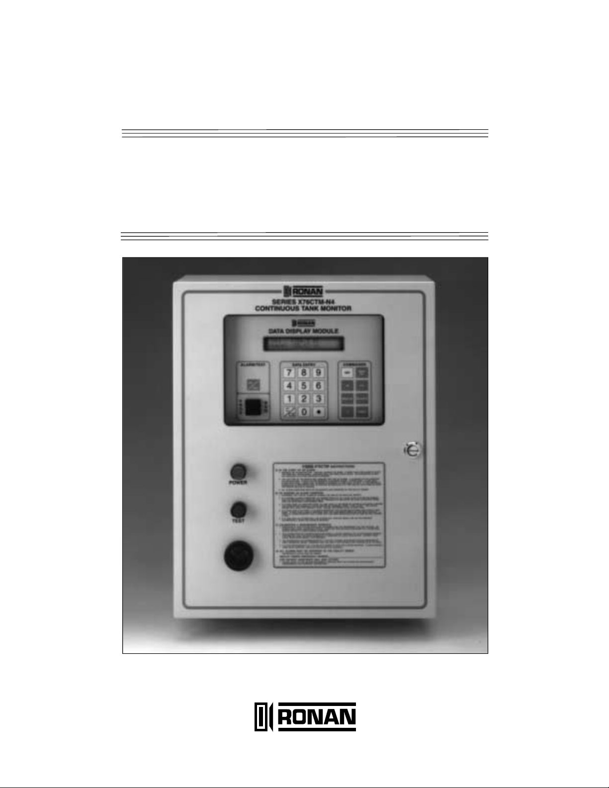
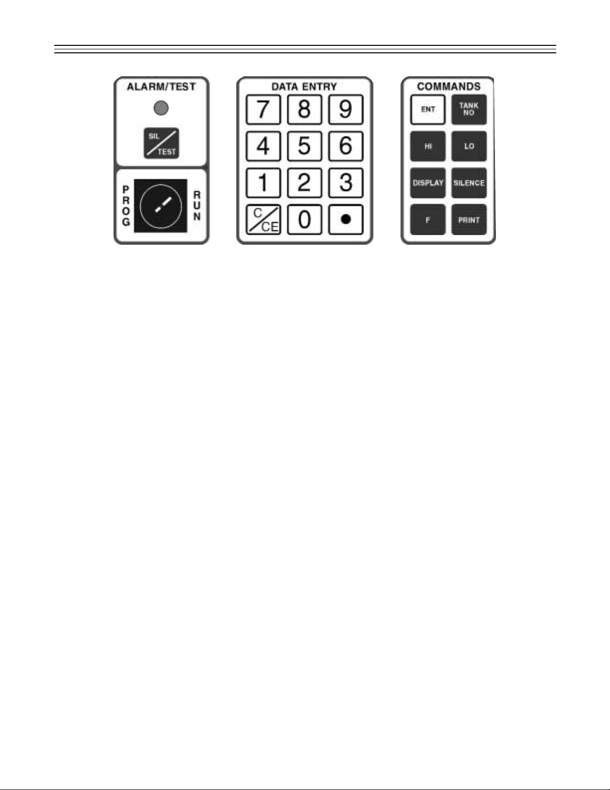
Figure 1: Keypad Push-button Layout.
4.0 KEYPAD EXTERNAL PUSHBUTTON FUNCTIONS
A TEST push button and a green POWER indicator
are provided in the external layer of the panel. Any
incoming alarms can be silenced through the TEST
push button. Under normal conditions, press this
push button to test the system horn. If the test is
successful, the external horn as well as the internal
horn will be heard. Open the cover to access the
X76CTM’s alphanumeric LCD that will display tank
and alarm information. The Display and Data Entry
Keypad are used to program the system and will
prompt you through the initial setup.The keypad is
shown above as it appears on the unit.Keypad
entries are divided into the following four types:
4.1 Alarm/Test and Sil/Test Keypad
The purpose of the SIL /TEST key is to
acknowledge alarms (reset).To test the internal audible and visual alarms press the
[SIL/TEST] push button.
When in the default display screen, it is possible to test the alarm light and horn by pressing the SIL/TEST or SILENCE keys. The horn
and light will be active for 5 seconds.
4.2 Data Entry Keypad
The numeric [0] - [9] keys provide quick and
easy numerical information input. Clear/Clear
Entry Key [C/CE] will clear or correct data
entry. It is also used for alphabetical information input.This key is used to scroll through
the alphabetical characters from right to left.
The Decimal Key [l] is used to enter a decimal point, colon, slash, or scroll through the
alphabetical characters from the left to right.
See Section 6.0 for editing parameters and
advanced keyboard functions.
4.3 Commands Keypad
Enter Key [ENT]. Used for data entry.
Tank Number Key [TANK NO]. Prompts user
to select tanks 1 through 8. It can also be used
to advance the tank number by depressing the
key twice.
High Level Key [HI]. Displays the set point of
the High Level Alarm in gallons for the tank
number displayed.It also scrolls through function codes available for configuration settings.
Low Level Key [LO]. Displays the set point of
the Low Level Alar m in gallons for the tank
number displayed.It also scrolls through function codes available for configuration settings.
Display Key [DISPLAY]. Changes the LCD
format from inches and gallons to temperature
and water level, time and date, and input
annunciator windows.
Function Key [F]. Pressed prior to function
codes.
Print Key [PRINT]. Pr ints a hard copy of the
following report selections:
1. Active Alarms Report. Pr ints all alar ms
that are currently active (all active contact
inputs and exceeded tank level set points).
2. Inventory Report. Prints the current level,
volume, and temperatures for all active
tanks.
3. Shift Report. Similar to the inventory
report, but also includes the net change of
the volumes and the temperature since the
last time this report was printed. Normally
it is printed every time the shift changes.
The date and time of the last report are
also printed.
Page 8

7
4. Daily Sales Report. Prints the amount of
product sold per tank for the last 24 hours
(from midnight to midnight) and includes
the number of days of available inventory
at current usage rate.
5. CSLD (Continuous Statistical Leak
Detection) Report. Prints the average
leak rate, the error range, the 95% confidence leak rate, and the conclusion
(passed, failed, inconclusive) for the current tank.The system allows selection of
time intervals for which the report is to be
generated.
6. Tank Setup. Prints the general tank informa-
tion: shape, size, types of product, probe
data, length, wire speed, repetition rate (for
Magnetek 7030), as well as the alarm setting for the tank, level, and limit alarms. Use
the [HI] and [LO] keys to toggle options.
7. Tank Chart Report. Prints the tank char t at
one inch level increments.
8. Annunciator Settings. Prints the current
setting for the annunciator: type of event,
relay assigned, horn enable/disable, as well
as scripts to be run at normal and alar m
conditions.
9. Contacts Settings. Prints the contact set-
tings: type (nor mally open/nor mally
closed), current state (alarm/normal), and
the relay to be activated depending on the
contact state.This report prints the setting
for all contacts, including the level gauge
probe inputs.
10. Relays Settings. Prints the current settings
for the X76CTM relays. For each relay
(total of 4 relays) the current state, logic
(normally open/normally closed), and the
time-out is reported. If the time-out is 0, the
relay will stay in this state until changed.
The time-out option is for unattended
stations to increase the external horn life, if
attached, or in applications in which a
pulse is required for remote alarm indication of multiple alarms (reflash).
5.0 USER LOGIN/LOGOUT
To operate and configure the X76CTM, the user
must log in using a PIN preconfigured by the
administrator.There are 10 predefined users: User 19 and User 0 (ADMIN). Only ADMIN is allowed to
change the system settings, as well as the Person-
nal Identification Number (PIN) for the other users.
Any user can change their own PIN at any time.
The procedure for changing the PIN is described in
Section 10.
When the X76CTM is in one of the default displays,
press any key (0-9) to identify the user to be
logged in.The X76CTM prompts for the PIN entry
of the user.The PIN is up to 6 digits long and during the process of entering the digits are substituted with asterisks (*) on the display. After entering
all the digits, press [ENT]. If the PIN entered
matches the number assigned to the user, the user
will be logged in. If the number does not match, an
error message will appear.
6.0 EDITING PARAMETERS
6.1 Editing Numeric Parameters
When editing a number, follow these rules:
a) If the first key pressed is a digit (0-9), the
current value is erased and the digit is
accepted.
b) Every digit entered (including the decimal
point) is shifted from right to left.
c) Press the [C/CE] key to delete the last digit
entered and shift the display to the right.
d) If the last digit is deleted, the display shows
a reading of 0.
6.2 Editing T ext Functions
When editing text, use the following functions:
[HI] [LO] Keys. Move the cursor left and right.
[C/CE] and [ l ] Keys. Scroll the letter under
the cursor.
[TANK NO] Key. Changes the case of the
letter under the cursor.
It is possible to enter a letter without scrolling
through all letters.This is achieved by assigning the letters to the numbers, as it is done on
a telephone keypad.Pressing once, the digit
is put under the cursor.Pressing the same
number up to 3 times will scroll through the
assigned letters for this number. The letters
are assigned as follows:
&-/ Assigned on 0
ABC Assigned on 1
DEF Assigned on 2
GHI Assigned on 3
JKL Assigned on 4
Page 9

8
MNO Assigned on 5
PRS Assigned on 6
TUV Assigned on 7
YZl Assigned on 8
Press the [TANK NO] key to toggle letter case.
7.0 DEFAULT DISPLAY
There are 4 real-time displays that can be used to
show different parameters continuously:
1.Level and volume for the current tank.
2. Water level and product temperature of the
current tank.
3.Date and time.
4.Tank and contact status.
The default display is selected by pressing the
[DISPLAY] key. Each time the key is pressed it
scrolls to the next of the four available displays.
When the Tank and Contact Status Display is
selected, the following characters are used to show
the status:
[ . ] Represents normal state of the contact.This is
applicable also if the unused probe inputs are
used for contacts.The nor mal state of the contact can be programmed to be either normally
open or normally closed.
[nn] Displays contact in alarm.
[Q] Tank is in quiet mode.In this mode, the tank is
inactive.However, the conditions do not exist
to enter a leak test.
[T] Tank is in leak test mode.
[D] Tank is in delivery mode (i.e., a delivery is tak-
ing place).
[S] Tank is in sale mode (i.e., a product is being
withdrawn).
[C] Tank is closed, but the probe terminal is not
used as a contact.
8.0 SETTING T ANK DAT A
The configuration of the X76CTM is designed to be
performed in sequential steps. Because every step
uses the data from the previous step (particularly
for tank parameter settings), it is important to follow
the steps below:
1.Configure tank geometry.
2.Configure the probes.
3.Configure the product.
4.Configure initial product levels.
5.Configure tank-based alarms: low, low-low,
high, high-high and maximum water level alarm.
Configuration of the station’s name and address, the
contacts, relays, the annunciator, and the product
information is order independent and can be done at
any time.
9.0 BROWSING & PRINTING
EVENT HISTORY
The X76CTM uses flash memory to store all of the
events. The event storage capacity is approximately
3000 events. In the event of overflow, the oldest
events are discarded.For typical station use, this is
about 2 years usage.Each event is time-stamped
and identified including users logged in at the time.
The X76CTM stores the following types of events:
Power Up. Each time the X76CTM is powered up, it
stores the date and time of power up.
User Login or Logout. User name and the date
and time of the event is logged in.
Contact Event. Contact number and state (alarm or
normal).
Tank Volume and Level Events.Low, low-low, high,
high-high, and high water stored, as well as the
state (alarm or normal).
Leak Test Results. When a leak test is completed,
records the test duration, leak rate measured, and
date and time of the test. Leak tests are star ted
automatically during quiescent conditions.The
X76CTM stores all of the results, and uses them for
Continuous Statistical Leak Detection (CSLD).
To browse the event history, use Function 100.It
always starts with the last event.Scroll through the
events using [HI, LO] keys. Press the [PRINT] key
and the X76CTM will print the event displayed on
the screen. If [PRINT] is pressed again, the
X76CTM prints the next 20 events. After pr inting the
events, the X76CTM will wait for [PRINT] to be
pressed again for the next 20 events, or [HI, LO] to
continue scrolling.
Events can be filtered by type, date and time. This
feature enables the user to make customized
reports. To select the type of events to be seen, use
Function 101. Select the type of event by using [HI,
LO] keys.Press [ENT.]. Select the start and end
times.The start time is by default the current time
minus 24 hours, and the end time is the current
time. Once changed to different values, the settings
will remain in effect. If C/CE is pressed while editing
Page 10

the times, the time is cleared and assumed not to
be used for filtering. If the event is tank specific, a
prompt for selecting the tank will be displayed
(some events like contact, login, and logout are not
tank related). After selecting the filter, the filtered
events will be browsed the same as F100.
10.0 FUNCTION CODES
The functions available for the X76CTM are listed in
Figure 2 by function number, description, and page
location for detailed programming information.
However, Section 10.0 has been outlined in the
proper programming sequence.
To execute a function, press the
.
key.The follow-
ing message appears:
Select function
Or scroll with (HI, LO) key
Enter the function code (if known) or use [HI] and
[LO] keys to scroll through the available functions.
The function appears with the description on the
second line of the LCD. When the desired function
is selected, press [ENT.].
Use the [DISPLAY] key at any time to cancel the
action and return to the current default display.
..
7021, Beginning Initial Programming
Each X76CTM is factory tested prior to shipping.
During the testing process many of the systems
functions are programmed. If this information is not
erased or reprogrammed, it may effect the performance of the system. It is suggested that the memory be cleared prior to programming the system for
the first time or if making substantial changes to the
system’s programming.
..
94, Station Name
This function sets the station name.The station
specific data is the station name, city, and address.
The device is programmed at the factory with the
manufacturer’s name, address, and city.
Station Name
Ronan Engineering Company
..
95, Station Address
Sets the station address.
Station address
21200 Oxnard St.
Function Description Page No.
Delivery Threshold
Set Up Contact [HI, LO]
Select Probe Type
Date & Time Format
[HI, LO]
Enter Tank Ullage %
Enter RTD-S Number
58 Software Version
62 Enter Code For:
63 Set Up Communications
66 Display Tank and
Contact Status
68 Manifolds to #12345678
72 Initial Product Level
73 Initial Water Level
74 Tank Model [HI, LO]
75 Leak Detect Threshold
76 High Water Level Alarm
78 Select Product [HI, LO]
79 Theft Detect Threshold
81 Set Up Relay [HI, LO]
82 Set Up Tank Alar m
84 High-High V olume Alarm
91 Enter Date & Time:
92 Enter Product Expansion
93 Select Units to Use
94 Station Name
95 Station Address
96 Station City
97 Enter Product Name
100 Browse Events
101 Event Query Filter
103 Print Report: [HI, LO]
184 Low-Low Volume Alarm
290 Disable Tank
291 Enable Tank
292 Enable Theft Monitor
7021 Beginning Initial Programming
Figure 2: Function Codes.
9
43
44
45
46
47
48
12
14
11
10
12
11
11
11
10
12
13
12
13
10
11
10
9
9
9
12
16
16
16
14
11
11
19
9
14
13
14
15
15
15
13
..
96, Station City
Sets the stations city, state and zip code.
Station City
Woodland Hills CA 91367
Page 11

10
..
46, Date & Time Format [HI, LO]
(Y2K Compliant)
Use this function to set up the time and date format. Use the [HI] and [LO] keys to scroll through
the selections.
Date & time format (HI,LO): 1
mm/dd/yy hh:mm:ss AM/PM
The X76CTM can operate with date and time in
different formats, to adapt for different countries.
The formats supported are:
1.mm/dd/yy hh:mm:ss US style
2.mm/dd/yyyy hh:mm:ss Displays full year,
US style
3.mm/dd/yy hh:mm:ss AM/PM, US style
4.dd-mm-yy hh:mm:ss European style
5.dd-mm-yyyy hh:mm:ss Displays full year,
European style
6.dd/mm/yy hh:mm:ss European style
7.dd/mm/yyyy hh:mm:ss Displays full year,
European style
..
91, Enter Date & Time
To set the time and date, use Function 91.With
the X76CTM, both the date and time can be
entered using this function.When entering the
time, it must be entered in military format (24
hours). Use the [HI] and [LO] keys to advance
the cursor to the corresponding digit.
Enter the date & time
03/02/98 15:18:49
..
93, Select Units to Use
The X76CTM defaults to US units.To change the
unit type, use Function 93. Enter the digit corresponding to the following choices:
Select units to use
1-US 2-Imperial 3-Metric
..
74,Tank Model [HI, LO]
The X76CTM has a predefined table of most of
the industry standard tanks strap charts (OwensCorning and Xerxes models). Press Function 74,
[ENT.] to generate the strap chart table.
Tank Model (HI,LO)_1
0/C2 (4) 1000 Owens-Corning
The X76CTM displays the following strap chart table.
User defined
0/C2 (4) 1000 Owens-Corning
0/C2 (6) 2500 Owens-Corning
0/C2 (6) 4000 Owens-Corning
0/C2 (6) 6000 Owens-Corning
0/C2 (8) 6000 Owens-Corning
0/C2 (8) 8000 Owens-Corning
0/C2 (8) 10000 Owens-Corning
0/C2 (8) 12000 Owens-Corning
0/C2 (10) 15000 Owens-Corning
0/C2 (10) 20000 Owens-Corning
0/C2 (10) 25000 Owens-Corning
0/C2 (10) 30000 Owens-Corning
X2 (4) 1000 Xerxes
X2 (6) 2500 Xerxes
X2 (6) 4000 Xerxes
X2 (6) 6000 Xerxes
X2 (8) 8000 Xerxes
X2 (8) 10000 Xerxes
X2 (8) 12000 Xerxes
X2 (10) 15000 Xerxes
X2 (10) 20000 Xerxes
X2 (10) 25000 Xerxes
X2 (10) 30000 Xerxes
For standard tanks where the strap table is known,
select 6, User Types.
Select shape (HI,LO)_6
User types
For non-standard tanks select from the following
shapes at the User Defined option:
1-Flat-end (for steel tanks)
2-Round-end (for fiberglass)
3-Vert. cyl
4-Spherical
5-Rectangular
Upon this selection, the strap table editing function
automatically begins.
1.Enter the tank internal diameter.
2.Enter the actual capacity.
3.Select one of the 2 choices for the tank tilt using
[C/CE].
4.If the tank is tilted, enter the probe location (1
for probe between the fill opening and the
center, 2 for fill opening between the probe and
the center).
5.Enter the distance between the probe and the
fill openings.
6.Enter the distance between the probe opening
and the center of the tank.
Page 12

11
7.Enter the dipstick level at the probe opening.
8.Enter the dipstick level at the fill opening.
..
45, Select Probe Type
Use this function to select the type of the probe,
and also to set up the probe parameters. Scroll
through the list of supported probes with [HI] and
[LO]. Select the desired model with [ENT.].
Select probe type:
Mt7100
Depending on the probe model, the X76CTM asks
for different parameters: serial number, wire speed,
and repetition rate (for Patriot’s 7030 probe only).
Entering the serial number is recommended, since
it is written in the flash memory for maintenance
purpose.
Enter probe serial #
2569273
Enter the probe’s wire speed (shown on the upper
end of probe), and press [ENT.] In the case of the
7030 probe, the X76CTM will prompt for the
probe’s repetition rate.
Enter speed of wire
9.250 ms/inch
NOTE: The speed of wire is located on the top of
the probe and should be recorded on the setup
sheet.The speed of wire must be entered before
initial product and initial water levels, otherwise
incorrect temperatures and levels will result.
Enter the probe length in inches. By default, the
probe’s length is calculated based on the tank
diameter and probe type.
Probe length
in
Enter the offset from the bottom of the tank, in
case the probe is not touching the bottom.
Offset from bottom
in
The option to disregard the water signal is used in
applications where the water level is not monitored.
Disregard water: NO
Use C/CE to toggle
Inventory only is used in applications where fast
polling of the probes is critical, and running leak
tests is not needed. Once the inventory only
option is confirmed, the X76CTM will not run leak
tests for the selected tanks.The inventory only
selection is recorded in the event log.
Inventory only: NO
Use C/CE to toggle
iWARNING:The tank parameters are changed
using Function 74. For the tank diameter, the length
of the probe will automatically recalculate to reflect
the new diameter. If the probe length is not matched
with the recalculated length, it must be changed
again.
..
48, Enter RTD-S Number
Use Function 48 to change the number of RTD’s in
the probe from the default number for that probe.
..
290/291, Disable/Enable T ank
These functions are used to enable/disable the
probe poling and tank calculations. It is recommended to close the tank before entering settings.
Enable the tank after the new settings are entered.
To open a tank for poling, use Function 291.To
close (disable) a tank, use Function 290.
..
72, Initial Product Level
The configuration setting of the initial levels are
required to calibrate the probe to the real level of
the product (Function 72) and water (Function 73)
in the tank.These settings are always overwritten
when the probe data type is changed and must be
re-entered.
Press Function 72 to set up the initial product (fuel).
Enter the fuel level in inches, and press [ENT.].
Initial product level
22.86 in
NOTE: Use a gauge stick and Kolor Kut™ paste
(or similar) to determine the initial level. If the tank
is tilted, measure the level at the probe riser.
..
73, Initial Water Level
Use Function 73 for initial water level. Enter inches
of water and press [ENT.].
Initial water level
0.00 in
NOTE: Before entering initial water level, take an
accurate reading of the water level in the tank using
Kolor Kut™ water finding paste or a similar product.
Failure to do so will result in false or inaccurate
water readings.
..
92, Enter Product Expansion
If Function 97 (Product Name) has been entered, a
coefficient of thermal expansion will be needed for
that product. Press Function 92, [ENT.] to enter a
coefficient of thermal expansion.
Page 13

12
Enter product expansion
0.00065
Enter coefficient of expansion and press [ENT.].
Function 92 is used when the product name cannot
be found in product codes.The coefficient can be
viewed or changed with this function. It is not necessary to enter the decimal point.
..
78, Select Product [HI, LO]
The X76CTM has predefined the most common
hydrocarbon fuel products.To select a product, use
Function 78.
Select product (HI,LO)_1
Use the [HI] and [LO] keys to scroll through the predefined list and select the chosen product.
0 = None
1 = Regular
2 = Premium
3 = Super
4 = Diesel
5 = Kerosene
6 = Toluene
7 = Hydraulic Oil
8 = #2 Heating Oil
9 = Turbine Oil
10 = Xylene
11 = Jet Fuel
12 = AV Gas
13 = Water
If the product is not listed, enter the product name
(to appear in reports) using Function 97, and its
coefficient of expansion using Function 92.
..
97, Enter Product Name
If a product is not listed in the predefined list
(Function 78), a new product name can be added
by using Function 97 and its corresponding expansion coefficient, using Function 92.
..
47, Enter Tank Ullage %
Press Function 47, [ENT.] for programmable ullage.
Message will display:
Enter tank ullage 95%
Enter the % and press [ENT.].
..
43, Delivery Threshold
When a product is delivered to a tank, the X76CTM
senses it and writes the date, time, amount, and
temperature of the delivered product.Sometimes, a
small amount of product pouring back in the tank
during transfer is not considered as delivery.To minimize confusion, the user can set up a value that
will eliminate the small levels. The default threshold
is 200 gallons. Use Function 43 to change the
delivery threshold and press [ENT.] to save.
Delivery threshold
100.0 gl
..
75, Leak Detect Threshold
X76CTM has 4 leak-related alarms: Quick Test,
Precise Test, High Leak, and CSLD (Continuous
Statistical Leak Detection).The function for each of
these alarms may be programmed independently
using F82.
The Quick Test is star ted automatically after a predefined, probe-dependent interval following a delivery (1 hour for X76MP, 7100, MTS-UST and
Veeder-Root MAG2).The result is compared to a
probe-specific threshold and, if a failure has
occurred, an alarm is generated.Testing immediately after a delivery is not precise, although still
within the EPA requirements. Ronan recommends
this result only as a leak indication, not as a basis
for programming station shutdown.
The Precise Test is run after a longer waiting period
following the deliver y.It guarantees more accurate
results and a lower number of false alar ms. Two
thresholds are possible for this test corresponding
to the 0.1 and 0.2 gallons/hour EPA requirements.
The thresholds are set automatically, and are probe
dependent. Normally, a station shutdown procedure
is specified for this alarm.
The High Leak alarm is activated whenever a gross
leak is detected.The leak must be higher than
9 gph, and lower than the minimal pump throughput. High Leaks occur when a pipe is broken, or the
tank is physically damaged.The High Leak detection alarm time is shor ter than a leak test, typically
less than 30 minutes.
The CSLD alarm is activated when long-term data
shows possible tank leakage.It is useful for busy
stations that do not have time to run a full test.
Since the result of the CSLD test is based on the
database compiled by short tests, it cannot be used
to confirm a leak. If a CSLD alar m occurs, the tank
must be shutdown and a full test, preferably a
Precise Test, has to be run.
To set up the leak test parameters, select F75.
Pressing [ENT.] at ever y parameter confir ms the
current value.
Leak scatter is a very important parameter, since it
defines when the tank is quiescent, and a test can
Page 14

13
..
68, Manifolds to t# 12345678
The X76CTM allows for the combining of two or
more tanks to generate the combined product volume of physically manifolded tanks. If tank 2 is
manifolded to tank 1, the reports for tank 1 will
contain the manifolded volumes, while those for
tank 2 will not.The same applies to the leak test.
The leak test for tank 1 will use the combined
product volume, while tank 2 will be independent.
Manifolding tanks is performed with Function 68.
The display has 8 characters for every tank where
the current tank is marked with a black block.
Manifolds to t# 12345678
1-8 to set/clr: ...* ...
Press the key, corresponding to the tank number to
be manifolded, to toggle the status of the tank (i.e.,
if tank is not manifolded, it will manifold and vice
versa). Pressing the digit that corresponds to the
current tank does not cause a change.To end
manifolding, press [DISPLAY].
..
76, High-Water Level Alarm
The high water alarm is set using Function 76.
High water level alarm
3.5 in
The high water alarm warns when the water level
has exceeded a preset level. When this set point is
exceeded, an audible/visual alarm is generated followed by a printout of the alarm.The high water
alarm can be programmed to an external output
relay (Function 81). Information on the last water
alarm warning for each tank is stored in memory.
..
79,Theft Detect Threshold
Use Function 79 to set up the theft detect threshold. A message will be displayed:
Theft detect threshold
10.0 gl
Enter the number of gallons loss that will make the
theft gallon alarm active and press [ENT.].
NOTE: This function is only active when in THEFT
DETECT MODE (Function 292).
..
82, Set Up Tank Alarm
The X76CTM can be configured to perform different actions when an alarm occurs. For each event,
a relay can be assigned.The events supported
are:
be conducted.The higher it is, the easier it is to
enter a leak test, but the data could be noisier and
the results incorrect
.
Leak scatter
0.2 gl
The activity threshold is used to distinguish tank
leakage from real activity - delivery of sale. It can
be increased to the minimal throughput of the dispenser pump.By default this is 9 gl/h.
Activity threshold
9.0 gl
Temperature scatter controls what temperature
slope is acceptable to start a test.
Temp scatter
0.2 deg/h
Minimum test duration sets the minimum acceptable test time to be used by the CSLD database.
Min test duration
15 min
A maximum test duration of 120 minutes is sufficient for tanks up to 20,000 gallons.Increasing this
duration usually will not improve the result and
degrade the response time.
Max test duration
120 min
Precise wait after delivery can be entered to increase the test precision, although it is not needed
in most cases.
Precise wait after delivery
360 min
This parameter allows the X76CTM to use a lower
threshold for the Precise Test. Generally, this
increases the probability of false alarms, but allows
for early warning of possible tank leak.
0.1 gph test? No
The minimum CSLD duration sets a minimum combined test time for the CSLD algorithm to make its
conclusions. Generally, the longer it is, the better.
Min CSLD duration
8 hours
The minimum history parameter sets the maximum
number of days to be used by CSLD to acquire the
minimal test duration. If there is not enough tests
for this period, increasing the number of days is
recommended. If it is not possible to acquire the
data for one month, the tank should be shutdown
and a normal test conducted.
Min CSLD history
14 days
Page 15

14
Edit the relay name, and press [ENT.]. (By default,
the relays are named RELAY1-4).
Enter relay name
Relay 1
Enter the relay time-out (0-255 s), and press
[ENT.]. Entering 0 means that there is no time-out.
Enter relay time-out
25 s
Select the relay logic (1 for normally open, 2 for
normally closed) using [C/CE].
Select relay logic
1-NormOpen 2-NormClose
..
44, Set Up Contact [HI, LO]
The X76CTM can have up to 16 contacts, depending on the number of active probes.Each contact is
enabled and set up individually. If some or all probe
terminals are not used with a probe, they can be
used as a contact input.
Scroll through the contacts using [HI] and [LO].
When the desired contact number and name is displayed, press [ENT.].
Set up contact (HI,LO)-1
INPUT 01
The X76CTM asks whether you want to enable the
contact. If the contact is not enabled, the function
ends without changes. If the contact is enabled, the
display prompts for the contact name. Enter or confirm the contact name.
Enable contact YES
Use C/CE to toggle
The next prompt allows you to select the contact’s
logic, either N.O.(normally open) or N.C. (normally
closed). Select the desired polarity using [C/CE].
Contact logic (use C/CE)
Norm. Open
Select the relay that will be energized when the
contact is in active (alarm) state. Select 0 for
NONE.
Select alarm relay (HI, LO) 0
NONE
After selecting the alarm relay, press [ENT.].
For the horn to sound while the contact is in alarm
state, the option must be entered using [C/CE].
Horn on alarm
use C/CE to toggle
The system will prompt to set up contacts names.
By default, all contacts have the name INPUT01 INPUT16.
Leak Detected. This event is made active when a
test with a maximal duration was ended, the probability of leak detection is higher than 95%, and the
leak detected was higher than the threshold (typically 0.2 gph).
High Leak Detected. This event is activated when
a maximal duration leak test is completed and the
leak detected is higher than the High Leak
threshold.
Low V olume Alarm. The volume of the product in
the tank is below the threshold.
Low-Low Volume.
High V olume Alarm. The volume of the product in
the tank is above the threshold.
High-High V olume.
High Water . The water level is above the threshold.
Probe Alarm. A probe failed or was restored.
To setup an event, select Function 82. Select the
type of the event to be programmed. Select the
relay to be assigned, or press [C/CE] to remove an
assignment. Select the horn activation flag by toggling the current selection using [C/CE].
..
84, High-High V olume Alarm
Use Function 84 to enter the High-High Volume
Alarm.
High-high volume alarm
9241.60 gl
Enter the number of gallons that will activate the
alarm and press [ENT.].
..
184, Low-Low Volume Alarm
Use Function 184 to enter the Low-Low Volume
Alarm.
Low-low volume alarm
924.16 gl
Enter the number of gallons that will activate the
alarm, and press [ENT.].
..
81, Set Up Relay [HI, LO]
The X76CTM has 4 user programmable relays. The
relays can be set up to respond to alarm conditions, or be controlled by commands in user
scripts.The name, logic, and time-out can be set
for every relay. To program a relay, use Function 81
and the [HI] and [LO] key.
Set up relay
Relay 1
Page 16

15
Setup contact (HI,LO)_1
Input01
Use [HI] and [LO] keys to scroll through the available contact listings.Press [ENT.] at the selected
contact and start editing.
Enter contact name:
Contact01
F63, Set Up Communications
The X76CTM has two serial ports that can be
assigned to support different protocols.They are
not totally interchangeable.Com 1 (J1) is used primarily as a remote access setup port. The only
exception to this use is when the port is being used
as a Ronan X110 interface.The second por t Com 2
(J3) is designed to support various protocols.
To set up ports, select Function 63. Select the por t
to be configured using the [HI] and [LO] keys.
Set up comport 0
Com 1
Select the port protocol. The X76CTM will assume
the default values for the next parameters, but it is
possible to change them.
Select the connection type:
Connection type 1
The three possible choices are:
1. Computer.This means connection will be made
with null modem cable and no hardware handshake
will be applied.
2. Modem. If chosen, the X76CTM will try to initialize the modem.
3. RS485. This assumes the Ronan supplied
RS485 adapters are present, and a multidrop connection will be used.
Select the baud rate using the [HI], [LO] keys.
Speed 9600 bps
HI,LO
Select the bits per character.Only 7 and 8 are
available.
Character bits 8
Select the parity using the [HI], [LO] keys.Choices
are odd, even, or none.
Parity = None
HI, LO
If the protocol selected is for daisychaining multiple
X76CTM’s, like MODBUS™, or TM2000 emulation,
enter the network address of the X76CTM.
..
62, Enter Current Code For:
To make a change to the PIN code, use Function
62. For security purposes, the X76CTM is designed
so that only the administrator can change user
codes.To change the code of another user, the
administrator must first log in. At the default display,
press the user number to be changed. A message
will appear requesting the PIN code of the specific
user.Ignore this message.
Enter PIN code for:
User 4 >_
To change, press Function 62 again, and a prompt
for entering the new PIN code will appear. For
security purposes, during the new entry, the real
digits are substituted with asterisks (*) on the display.The requirement for the PIN code entr y is
numeric only. Up to six digits can be entered. Press
[ENT.] to make the changes active.
New PIN code for:
User 4 >******_
..
58, Software Ver sion
Use this function to display the current version of
the software and the corresponding date and time.
X76CTM version 1.0
Built 02/16/98, 14:24:21
..
66, Display Tank and Contact Status
When the Tank and Contact Status Displays are
selected, the following characters are used to show
the status.
[ . ] Represents normal state of the contact.This is
applicable also if the unused probe inputs are
used for contacts.The nor mal state of the contact can be programmed to be either normally
open or normally closed.
[nn] Displays contact in alarm.
[Q] Tank is in quiet mode.In this mode, the tank is
inactive.However, the conditions do not exist
to enter a leak test.
[T] Tank is in leak test mode.
[D] Tank is in delivery mode (i.e., a delivery is tak-
ing place).
[S] Tank is in sale mode (i.e., a product is being
withdrawn).
[C] Tank is closed, but the probe terminal is not
used as a contact.
Page 17

16
Report 1: Active Alarms. Report 2: Inventory Repor t.
..
100, Browse Events
This function is used for unconditional and unfiltered display of the events
from the event log, always beginning
with the most recent event.
To browse the event history, use
Function 100.This display defaults to
the last event.To scroll through the
list of events use the [HI] and [LO]
keys.Pressing the [PRINT] key
prompts the X76CTM to print the
event that is on the screen.If
[PRINT] is pressed again, the next
20 events will be printed.After printing those events, if [PRINT] is
pressed again an additional 20
events will print, or [HI] and [LO] can
be used to continue scrolling through
the event history.
..
101, Event Filter Query
Use this function to selectively display events from the event log, filtered by type, start/end times, and
tank. Browse the list of available
event types. Select the event type
with [HI] and [LO]. Use 255 for all
event types.
Event query 255 filter
All
Enter start and end times to select a
specific range of events. The end
time (the most recent event) is displayed first.If an end time is not
entered, the system defaults to 24
hours from the start time:
Query event: start
9/18/99 13:00:00
Query event: til
9/19/99 13:00:00
If a query by start/end time is not
required, press the clear key [C/CE]
to bypass this filter.
The system will prompt for tank filter
if the event type is per tank based.
Filter by tank
All
The events can be browsed and
printed the same as in Function 100.
..
103, Print Report [HI, LO]
Function 103 prints a hard copy of the following report selections:
1. Active Alarms Report. Prints all alar ms that are currently
active (all active contacts and tank level limit set points).
2. Inventory Report. Prints the current level, volume, and tem-
peratures for all active tanks.
3. Shift Report. Similar to the inventory report, but also includes
the net change of the volumes and the temperature since the
last time this report was printed. Normally it is printed every
time the shift changes.The date and time of the last report are
also printed.
4. Daily Sales Report. Prints the average daily sales for each
day of the week for the last month, as well as the number of
days remaining until the tank reaches low level, based on the
average sales.
5. CSLD (Continuous Statistical Leak Detection) Report.
Prints the average leak rate, the error range, the 95% confi
dence leak rate, and the conclusion (passed, failed, inconclu
sive) for the current tank.The system allows selection of time
intervals for which the report is to be generated.
6. Tank Setup. Prints the general tank information: shape, size,
types of product, probe data, length wire speed, repetition rate
(for Magnetek 7030), as well as the alarm setting for the tank,
level, and volume alarms.
7. Print T ank Chart. Prints the tank char t at one-inch level
increments.
8. Annunciator Settings.
Prints the current setting for
the annunciator: type of
event, relay assigned, horn
enable/disable, as well as
scripts to be run at normal
and alarm conditions.
Page 18

17
Report 4: Daily Sales Repor t.
Report 3: Shift Repor t.
Report 5: CSLD Repor t.
9. Contacts Settings. Prints
the contact settings: type
(normally open/normally
closed), current state alarm/
normal), and the relay to be
activated depending on the
Page 19

18
Report 6: Tank Setup. Report 7: Tank Chart Report. Report 8: Annunciator Settings.
prints the settings for all contacts, including the level
gauge probe inputs.
10. Relays Settings. Prints
the current settings for the
76CTM relays.For each relay
(total of 4 relays) the current
state, logic (normally open/
Ronan Engineering LDM
21200 Oxnard Street
Woodland Hills CA 91367
Annunciator settings
** 08/06/99 10:29:08 **
on Contact
Relay: none
Horn: Yes
Scripts:
Normal: none
Alarm: none
X110: 0
* Settings for tank 3 *
----------------------on Probe
Relay: RemoteCTA
Horn: No
Scripts:
Normal: none
Alarm: none
X110: 1
on Low
Relay: RemoteCTA
Horn: No
Scripts:
Normal: none
Alarm: none
X110: 2
on LowLow
Relay: RemoteCTA
Horn: No
Scripts:
Normal: none
Alarm: none
X110: 3
on High
Relay: RemoteCTA
Horn: No
Scripts:
Normal: none
Alarm: none
X110: 4
on HighHigh
Relay: RemoteCTA
Horn: No
Scripts:
Normal: none
Alarm: none
X110: 5
on HiWater
Relay: RemoteCTA
Horn: No
Scripts:
Normal: none
Alarm: none
X110: 6
on Theft
Relay: RemoteCTA
(Continued)
Page 20

19
Report 8 (Cont.)
Report 9: Contacts Settings.
Report 10: Relays Settings.
Horn: No
Scripts:
Normal: none
Alarm: none
X110: 7
on QuickTest
Relay: none
Horn: Yes
Scripts:
Normal: none
Alarm: none
X110: 8
on PreciseTest
Relay: none
Horn: Yes
Scripts:
Normal: none
Alarm: none
X110: 8
on HiLeak
Relay: none
Horn: Yes
Scripts:
Normal: none
Alarm: none
X110: 8
on Csld
Relay: none
Horn: Yes
Scripts:
Normal: none
Alarm: none
X110: 8
Ronan Engineering LDM
21200 Oxnard Street
Woodland Hills CA 91367
** Contacts settings **
** 08/06/99 10:29:20 **
1 SupPipeSump
State: Normal
Logic: Norm.Open
Relay: SuperPSD
2 SupFullSump
State: Normal
Logic: Norm.Open
Relay: SuperPSD
3 SupAnnular
State: Normal
Logic: Norm.Open
Relay: SuperPSD
4 RegPipeSump
State: Normal
Logic: Norm.Open
Relay: UnleadedPSD
5 RegFullSump
State: Normal
Logic: Norm.Open
Relay: UnleadedPSD
6 RegAnnular
State: Normal
Logic: Norm.Open
Relay: UnleadedPSD
7 RegPipeSump
State: Normal
Logic: Norm.Open
Relay: RegularPSD
8 RegFullSump
State: Normal
Logic: Norm.Open
Relay: RegularPSD
9 Probe input
10 Probe input
11 Probe input
12 RegAnnular
State: Normal
Logic: Norm.Open
Relay: RegularPSD
13 Disp#1
State: Normal
Logic: Norm.Open
Relay: none
14 Disp#2
State: Normal
Logic: Norm.Open
Relay: none
15 Disp#3
State: Normal
Logic: Norm.Open
Relay: none
16 Spare
State: Normal
Logic: Norm.Open
Relay: none
Ronan Engineering LDM
21200 Oxnard Street
Woodland Hills CA 91367
*** Relays settings ***
** 08/06/99 10:29:27 **
1 SuperPSD
State: Open
Logic: Norm.Open
Timeout: 0 s
2 UnleadedPSD
State: Open
Logic: Norm.Open
Timeout: 0 s
3 RegularPSD
State: Open
Logic: Norm.Open
Timeout: 0 s
4 RemoteCTA
State: Closed
Logic: Norm.Closed
Timeout: 30 s
normally closed), current
state (alarm/normal), and
the relay to be activated
depending on the contact
state.This report prints the
settings for all contacts,
including the level gauge
probe inputs.
10. Relays Settings. Prints
the current settings for the
76CTM relays.For each relay (total of 4 relays) the
current state, logic (normally open/normally closed)
and the time-out is reported. If the time-out is 0, the
relay will stay in this state
until changed.The time-out
option is for unattended
stations, to increase the
external horn life, if
attached or in applications
where a plulse is required
for remote alarm indication
of multiple alarms (reflash).
..
292, Enable Theft
Monitor
The theft alarm is defined as
the activity of the tank (sale or
withdrawal) when the tank is
declared as inactive.To star t
theft monitoring, use Function
292.The current net volume is
recorded and the system monitors the net volume for changes.
If the net volume decreases
more than the threshold value
(default 10 gal), a theft alarm is
generated.The net volume
change will be recorded. For
every occurrence, the amount is
recorded, until the function is
disabled.The theft monitoring
can be disabled using Function
291.
10.1 Setting the User Pin
For security purposes,
the X76CTM is designed
so that only the adminis-
Page 21

20
Register Parameter Name Dimension Data Style
1
Product Level. Inches Floating Point
2
3
Water Level. Inches Floating Point
4
5
Product Gross Volume. Gallons Floating Point
6
7
Total Gross Volume. Gallons Floating Point
8
9 Product Average Temperature.The average of the submerged
°F Floating Point
10 thermistor temperature.
11 Product Net Volume.The volume calculated when the product
Gallons Floating Point
12 temperature is 60°F.
13 Current CSLD (Continuous Statistical Leak Detection) Leak Rate. Gallons
Floating Point
14 Rate is based on at least one month test history. per Hour
15 Last Completed Leak Test Rate.A test that has not been canceled Gallons
Floating Point
16 before the scheduled test duration has expired. Per Hour
17 Time of Last Completed Test.Time is in UNIX format (32 bit
Seconds
Unsigned Long
18 integer, number of seconds since January 1, 1970). Number
19 Tank Status. A field with different flags that correspond to tank Unsigned Long
20 alarms. Number
21
Scaled Product Level. 0.001 Inches
Unsigned Long
22 Number
23
Scaled Water Level. 0.001 Inches
Unsigned Long
24 Number
25
Scaled Product Gross Volume. 0.001 Gallons
Unsigned Long
26 Number
27
Scaled Total Gross Volume. 0.001
Unsigned Long
28 Number
29 Scaled Product Average Temperature.The average of the sub-
0.001°F
Unsigned Long
30 merged thermistor temperatures. Number
31 Scaled Product Net Volume.The calculated volume when the
0.001 Gallons
Unsigned Long
32 product temperature is 60°F. Number
33 Scaled Current CSLD (Continuous Statistical Leak Detection) 0.001 Gallons Unsigned Long
34 Leak Rate. Based on a least one month test history. per Hour Number
35 Scaled Last Completed Leak Test Rate.A test that has not been 0.001 Gallons Unsigned Long
36 canceled before the scheduled test duration expired. per Hour Number
37-50 Reserved.
Modbus™ Register Allocations
trator can access and alter the user codes.
Function 62 is used to change the PIN codes.
During new code entry, the numbers are substituted with asterisks (*) on the display for
additional security. The administrator should
first log in, then enter the new user number.
This starts the login procedure for the new
user.When Function 62 is pressed, a prompt
for entering the user’s PIN will appear.
For example:To change the PIN for user 4,
log in as administrator, pressing 0.Enter the
PIN code for administrator.The default display will appear. Press 4.The X76CTM will
prompt to enter the user 4 PIN number.Disregard prompt and press Function 62.The
system will prompt again for the new user 4
PIN number. Enter the new code.
10.2 Modbus™ Support
The X76CTM supports Modbus™ protocol in
both ASCII and RTU modes.The mode is
selectable via the front panel or the text terminal interface.For constant reading of the
tank information, the RTU mode is recommended because of the small data overhead.
10.2.1 Register Allocation. The system data
accessible through Modbus™, is on a per
tank basis.The variables are sent in IEEE
4 bit floating point format or as 4 bit scaled
integer long numbers, for devices that do not
Page 22

21
support the floating point format. Although
the Modbus™ register in the Read Multiple
Registers Command (03) is 16 bit wide,
each floating point or unsigned long number
will occupy 2 registers.The register allocations for the tanks are shown in the table
on page 20.
The last registers are reserved for future
use.The data for the next tanks occupy the
next 350 registers at 50 registers per tank,
with the same register allocations
11.0 SPECIFICATIONS
11.1 Model X76CTM System
Power Requirements: 115/230 Vac,
50/60 Hz ±10%.
Power Consumption: 50 VA.
Operating Temp.: 32 to 125°F (0 to 52°C).
Mounting: NEMA 4, indoor or outdoor area,
wall mount.
Display: Alphanumeric LCD, 2 lines x 24
characters per line.
Probe Inputs: One (1) to eight (8).
Sensor Inputs: Up to 16 passive inputs
24 Vdc, 12 mA.
Remote Communication Ports: Two (2)
RS232C Serial Interface Por ts.
Auxiliary Relay Outputs: Four (4) SPDT,
120 Vac max., 7.5 A max.
Data Entry Keypad: Three section mem-
brane.
Printer: Alphanumeric paper, impact, 2¼ in.
wide x 75 ft. (24 characters wide).
Dimensions: 12 in. W x 15½ in.H x
6-3/32 in. D.
Alarms: LED & Sonaler t; 80db @ 10 ft.
(115 V ac power only).
Approvals: UL 48RO.
11.2 Gauging Probe, Model 95040XB
and Model 95140XB
Power Requirements: 24 Vdc intrinsically
safe, pulsed, supplied by control chassis.
Operating Temperature: -40 to 130°F
(-40 to 54°C) (consult factory for other
temperature ranges).
Probe Material: 316 stainless steel (consult
factory for other material types).
Float Material: Ceon-D, X95040XB;316SS,
95140XB.
Repeatability: .02% or full range.
Accuracy: .05% of full range.
Resolution: ± .001 in.
Site Characteristics: 4 in. schedule 40 riser.
Wiring: Two (2) conductor shielded cables,
max. length 2500 ft.
Approvals: UL Listed 48RO, intrinsically safe
for use in hazardous locations, Class I, Div.
1, Groups C & D; Class II, Div.1, Groups E,
F, & G; Class III, Div. 1.
11.3 Leak Sensor, Models LS-3, LS-3s,
and LS-3ss
Housing: 304 stainless steel.
Mounting: ½ in. NPT male thread.
Switch:
Type: SPST, N.O.or N.C.
Rating: 10 V A.
Float Material: Buna-N (LS-3, LS-3s).
316 stainless steel (LS-3ss).
Pressure: 50 psi maximum.
Leads: 20 AWG.
Test Mechanism: Stainless steel cable
(LS-3s).
Application: Ver tical position liquid detection.
Approvals: UL Listed 48RO.
11.4 Tank Leak Sensor, Model LS-7,
and LS-7s
Housing: PVC.
Liquid Specific Gravity: 70 minimum.
Switch:
Type: SPST, N.C.
Rating: 10 V A.
Float Material: PVC.
Pressure: 50 psi maximum.
Leads: 20 AWG.
Test Mechanism: Stainless steel cable
(LS-7s).
Application: Horizontal position liquid
detection.
Approvals: UL Listed 48RO.
11.5 Hydrostatic Leak Sensor,
Model LS-30
Housing: 304 stainless steel.
Mounting: ½ in. NPT male thread.
Page 23

22
Switch:
Type: DPDT, N.C.top, N.O. bottom.
Rating: 10 V A.
Float Material: Polysulfone.
Pressure: 50 psi maximum.
Leads: 20 AWG.
Application: Ver tical position high/low level.
detection, 4 in. separation.
Approvals: UL Listed 48RO.
11.6 Tank Leak Sensor Models JT-2P & 2V
Sensor Housing: Aluminum body with ¼ in.
stainless steel inlet, explosion proof, hermetically sealed, NEMA types 7 and 9.
Manifold: Brass, 1 in.NPT male thread
(JT-2P, JT-2V).
Classification: Class I, Groups A, B, C, and
D; Class II, Groups E, F, and G.
Switch:
Type: SPDT, N.O.(shelf condition).
Rating: 10 V A.
Electrical Connection: ½ in. NPT with PVC
insulated 18 AWG color coded leads.
Pressure:
Connection: ¼ in. NPT.
Adjustment: Allen wrench through port.
Proof Pressure: 299 psi.
Gauge: 0-30 psi (JT-2P), 0-20 in. Hg (JT-2V).
Temp.Range: -40 to 180°F (-40 to 82°C).
Approvals: UL Listed 48RO.
Page 24

23
X76CTM INTERNAL
WIRING DIAGRAM
POWER
LIGHT
B
RECEPTACLE
16 AWG.
BOTTOM
VIEW
BLK
H
N
GRN
WHT
G
18 AWG.
V+
WHT
A
TEST
SWITCH
2
a
b
1
HORN
16 AWG.
LINE
FILTER
BLK
BLK
BLK
BLK
V-
#6 RING RUGSTYP.
GRN
12 AWG.
BLK
WHT
RED
BLK
18 AWG.
BLU
16 AWG.
RED
J2
J4
RED
XIN2
XIN1
COM
GND
HI
LO
M
5
C
O
4
L
X
1
AUX4
AUX3
AUX2
AUX1
FROM DOOR
OF ENCLOSURE
PRINTER
CABLE DWG.
X76B470-2
2
1
3
14
L
L
L
X
X
X
2
3
4
J5
CONTROLLER
X76-5005A
TYPICAL WIRING
-1 THRU -4
-1 & -3
115 VAC INPUT
NOTES:
1. All wiring to be UL1430, 300V, 105°C.
2. J4 (2 thru 5) & J2 (XIN2, XIN1 & COM) wires are 30 inches long.
3. Cut 64 inches from the end.
4. Reference Ronan Engineering Drawing Number X76D655.
PCB
FROM DOOR
OF ENCLOSURE
CABLE DWG.
1
1
DISPLAY
X76B470-2
TO
MODEM KIT
1
6
2
7
3
8
4
9
5
J6
25
7
J3
3
2
14
1
25
J1
7
3
2
14
1
SERIAL
3
2
TO
PORT
5
SEE SERIAL
CABLE
ASSEMBLY
DWG.X76C669
3
5
2
TO
MODEM
PORT
SEE MODEM
CABLE ASSEMBLY
DWG.X76C668
TO MODEM KIT
16 AWG.
-2 WITHOUT MODEM
POWER SUPPLY
MODEM
POWER
SUPPLY
SEE NOTE 3
GRN
BLK
LINE
FILTER
WHT
N
G
H
-2 & -4
220 VAC INPUT
12 AWG.
BLK
WHT
#6 RING
RUGSTYP.
GRN
BRN
BLU
P1
16 AWG.
GND
HI
LO
Page 25

24
13.500”
(342.90 mm)
15.500”
(397.70 mm)
1.000”
(25.40 mm)
0.312” Dia.
(7.67 mm) 4 Plcs.
DATA DISPLAY MODULE
ALARM/TEST
DATA ENTRY
7
4
P
R
O
G
12.000” (304.80 mm)
1
R
U
C
N
CE
8.000” (203.00 mm)
A
11
20
37
43
6
33
3
8
5
2
COMMANDS
9
6
3
0
39
44
1
4
17
18
39
44
5.625” Dia.
(142.88 mm)
13
38
14
15
32
39
44
19
16
25
27
29
24
26
28
7
A
12
22
23
33
SECT A-A
10
37
30
43
AC POWER INPUT
AUX.OUTPUT
I.S.FIELD INPUT
8
31
35
34
MODEM PORT (COM 1)
SERIAL PORT (COM 2)
35
34
9
31
Page 26

X76CTM
ASSEMBLY DRAWING
Item Model No. Description
X76D640-1 X76CTM-1 Assembly (115 Vac)
X76D640-2 X76CTM-2 Assembly (220 Vac)
X76D640-3 X76CTM-3 Assembly
(115 Vac with Modem)
X76D640-4 X76CTM-4 Assembly
(220 Vac with Modem)
1 X76D641-1 Enclosure Assembly
2 X76D648-1 Controller PCB Assembly
X76D648-2 Controller PCB Assembly
3 X76C334 Data Display Module Assembly
4 X76C331 Pr inter Assembly
5 X76C650-1 Mounting Panel Assembly
X76C650-2 Mounting Panel Assembly
X76C670-1 Mounting Panel Assembly
X76C670-2 Mounting Panel Assembly
6 X76C470-1 Display Cable Assembly
7 X76C470-2 Printer Cable Assembly
8 X76C668 Modem Cable Assembly
9 X76C669 Ser ial Cable Assembly
10 X76C332 Mounting Plate
11 X76C338 Enclosure Cover
12 X76B469 Washer, Horn
13 X76B653 Modem Mounting Plate
14 X76B663 Clamp, Right
15 X76B664 Clamp, Left
16 X76C654-1 Instruction Label
17 X76C654-2 Instruction Label
18 X76C654-3 Instruction Label
19 X76C647 Mounting Plate
20 X76B705 Flush Latch Modification
21
22 SC628 Horn
23 BNR-1 Ring, Horn
24 51-435.036 Push Button, Lighted
25 51-030.005 Indicator, Power
26 51-931.2 Lens, Red
27 51-931.5 Lens, Green
Item Model No. Description
28 31-968.2.2 LED, Red
29 31-968.2.5 LED, Green
30 ST-2 Hub
31 94F720 Weathertight Connector Cap
32 PKT-14.4/EXT Modem (External)
33 FCC-A-CB Flat Cable Mounts
34 ABMM-A-C Tie-Wrap Mount
35 FCC-D8 Tie-Wrap
36
37 0632 x 0086 6 - 32 x 1/4 PH RD HD MS
PHPHMS
38 0632 x 0086 6 - 32 x 1/4 PH Flat HD MS
PHFHMS
39 0440 X 0086 4 - 40 x 1/4 PH RD HD MS
PHPHMS
40
41 8 - 32 Hex Nut
42 #8 Intertooth Lockwasher
43 #6 Intertooth Lockwasher
44 #4 Intertooth Lockwasher
NOTES:
1. For wiring diagram reference Ronan Engineering Drawing
Number X76D655.
2. For sub assembly drawings reference Ronan Engineering
Drawing Numbers X76D48 and X76C650.
25
Page 27

26
X76CTM TYPICAL
INSTALLATION DRAWING
SERIES
X76CTM-4X
INSIDE WALL
WIRE CONDUIT
WIRE FROM
PROBE
WATERTIGHT
WIRE
CONNECTOR
SHIELD
GROUND
WIRE CONDUIT
JUNCTION BOX
(COVER
REMOVED)
OPTIONAL WIRE
TO NEXT PROBE
PRODUCT
WATER
TANK
VAPOR
SEAL
CABLE
GRIP
OUTSIDE
WALL
GROUND LEVEL
MANHOLE
PROBE WIRE
CABLE GRIP
950 CAP
4" PIPE RISER
4" TANK
BUSHING
16" MIN.
950 4"TOP
SEAL ADAPTOR
PROBE CODE
REP.RATE/SPEED
OF WIRE
950-___B
951-___B
PROBE
NON-HAZARDOUS HAZARDOUS
"WATERPROOF JUNCTION"
DETAIL A
WATERPROOF
JUNCTION BOX
(SEE DETAIL A)
NOTE: Reference Ronan Engineering
Drawing Number X76D510.
Page 28

27
LS-3
N.O.OR N.C.
CONTACTS
LS-7
N.C.
CONTACTS
JT-2P
JT-2V
N.O.OR N.C.
CONTACTS
LS-30
N.C.
CONTACT
N.O.
CONTACT
TYPICAL CONTACT SENSORS
950xxxB OR 951xxxB PROBE
U.L.LISTED INSTRINSICALLY SAFE
FOR USE IN HAZARDOUSLOCATIONS
CLASS I, DIV.1, GRPS.C&D;
CLASS II, DIV.1, GRPS.E,F&G;
CLASS III, DIV.1
APPROVEDSEAL
IE: EXPLOSION PROOF
CONDUIT SEAL
CONDUIT
SHIELDED CABLE
(SEE CABLE NOTE)
SEALED JUNCTION BOX
G
_
+
CONTACT
CLOSURES
HAZARDOUS LOCATION
NON HAZARDOUS LOCATION
TO ADDITIONAL
PROBES
AS REQUIRED
WIRE IDENTICAL
AS ABOVE
TO ADDITIONAL
CONTACT
AS REQUIRED
WIRE IDENTICAL
AS ABOVE
WHITE
COM
COM
XIN1
XIN2
COM
COM
COM
NC
NC
NC
NC
NC
NO
NO
NO
NO
RELAY#4
RELAY#3
RELAY#2
RELAY#1
INSTRINSICALLY
SAFE PROBE
TERMINALS
OPTIONAL RELAY
CONTACT OUTPUTS
120 VACMAX.
7.5 AMP MAX.
TO DOOR OF ENCLOSURE
DISPLAYCONNECTOR
PRINTER
CONNECTOR
INTRINSICALLY SAFEOUTPUTS
CONTACTS
PROBES
RS232
B CHANNEL
CONNECTOR
RS232
A CHANNEL
CONNECTOR
FOR WIRING
DETAILS
SEE DRW.
X76D474-1
FOR WIRING DETAILS
SEE DRW.X76D474-1
INSTRINSICALLY
SAFE CONTACT
TERMINALS
+
1
2
3
3
1
1
3
3
4
4
5
5
6
6
7
7
8
8
2
2
2
1
_
_
_
_
_
_
_
_
_
_
_
_
_
_
_
_
_
_
_
_
_
_
+
+
+
+
+
+
+
+
+
+
+
+
+
+
+
+
+
+
+
+
+
BLACK
LINE
NOISE
FILTER
120 VAC
0.4 AMP
60 Hz
GND
HI (H)
LO (N)
C
O
M
L
X
1
L
X
2
L
X
3
L
X
4
X76CTM-4X
TANK MONITOR
GROUNDING NOTES
CABLE NOTES
INTRINSICALLY SAFETERMINAL NOTES
1.The resistance between the ground screwand the system
earth ground must be < 1 Ohm.
2.The transducer ground wire shall be connected to drain wire
or shield wire of cabling.Do not terminate drain wire at panel.
1. Probe terminals may only be connected to U.L. listed 950xxxB
model probes (xxx = probe length).
2. Contact terminals may only be connected to passive contacts.
3.Wiring shield covermust be installed securely in place prior to
applying operating power.
1. Cable sets that run together must be installed per ISA
Standard #RP126.
2. For transducer cable lengths up to 1000 ft., shielded cable
(#8441 Belden or equivalent) or heavier gauge can be used,
cable capacitance shall be < 60 pF per foot.Cable
inductance shall be < 0.2 H per foot.m
3. For contact cablelengths up to 1000 ft., unshielded twisted
pair cables are recommended. Cable capacitance shall be
<60pFperfoot. Cable inductance shall be < 0.2 H per foot.
4. For transducer and/or contact cable lengths exceeding 1000 ft.
and up to 2500 ft., twin axial Belden cable #9182 (U.L. 2606)
must be used.
m
X76CTM SYSTEM
WIRING INFORMATION
NOTE: Reference Ronan Engineering
Drawing Number X76D515.
X76CTM
TANK MONITOR
Page 29

28
X76CTM MODEM & SERIAL
CABLE ASSEMBLIES
1
1
1
2
2
2
3
3
4
5
3
7
BLUE
BLUE
BLACK
BROWN
BROWN
BLACK
SHIELD
DB25S
7282-6SG-300
DE9P
5
CABLE WIRING
4
6
1
2
5
3
1
TO J1
CONTROLLER
BOARD
COM 1
TO
MODEM KIT
MODEM
PORT
COM 1
PIN 1
PIN 1
PIN 1
1.00”TYP.
± .50
11.00”
13.00”
PART NUMBER
BOTH
ENDS
1
1
2
2
3
3
BLUE
BROWN
BLACK
SHIELD
7282-6SG-300
DB25S
7
5
4
2
1
3
4
1
SERIAL
PORT
COM 2
PIN 1
PIN 1
TO J3
CONTROLLER
BOARD
COM 2
1.00”TYP.
± .50
15.00”
BOTH ENDS
PART NUMBER
CABLE WIRING
Modem Cable Assembly
Serial Cable Assembly
Item Model No. Description
1 9536 Cable
2 7282-6SG-300 Connector
3 DE9P Connector, 9 Pin, D-Type (Female)
4 DB25S Connector, 25 Pin, D-Type (Female)
5 DDM090003BSK1 Back Shell with Hardware
6 DDM250003SK1 Back Shell with Hardware
Item Model No. Description
1 9536 Cable
2 7282-6SG-300 Connector
3 DB25S Connector, 25 Pin, D-Type (Female)
4 DDM250003SK1 Back Shell with Hardware
NOTES: Unless otherwise specified.
1 Jacket strip Length is 1.000 inch.
Reference Ronan Engineering Drawing Number X76C668.
NOTES: Unless otherwise specified.
1 Jacket strip Length is 1.000 inch.
Reference Ronan Engineering Drawing Number X76C669.
Page 30

X76CTM 9 PIN AND 25 PIN
CABLE ASSEMBLIES
TO HOST RS232 CABLE
5
1
2
3
4
HOST
DE9S
NU
2
2
3
3
5
5
X76CTM
6282-6PG-3XX
3
PINS
13
THRU
1
PINS
25
THRU
14
7
2
3
NU
2
3
5
1
2
X76CTM
6282-6PG-3XX
HOST
DE25P
4
1
6
5
4
3
2
1
6282-6PG-3XX
PIN LOCATION
VIEW FROM
WIRING SIDE
DE25P
PIN LOCATION
VIEW FROM
WIRING SIDE
9 PIN CONNECTOR CABLE ASSEMBLY
25 PIN CONNECTOR CABLE ASSEMBLY
NOTE: Cable length per customer order.
Maximum length 25 ft.
NOTE: Cable length per customer order.
Maximum length 25 ft.
29
9 Pin Cable Assembly
25 Pin Cable Assembly
Item Model No. Description
1 9536 Cable
2 6282-6PG-3XX Connector
3 DE9S Connector, 9 Pin (Female)
4 DDM090003BSKI Back Shell
5 DB110963-1 Cover
Item Model No. Description
1 9536 Cable
2 6282-6PG-3XX Connector
3 745496-2 Connector, 25 Pin IDE (Male)
4 745173-3I Shell with Hardware
Page 31

30
TANK LEAK SENSORS
MODEL LS-3, LS-3S, AND LS-3SS
BLACK
INSTALLATION INSTRUCTIONS
FOR STEEL DOUBLE WALL TANKS
Lower sensor on cable until it rests on bottom of tank annulus in a ver tical
position. Pull the remaining cable into the junction box and cut off the excess
length. Secure cable to prevent slipping into the tank annulus. Connect leads
to wire from the tank monitor input terminal strip.
OTHER APPLICATIONS
High level alarm for overfill prevention in the tank sump leak sensor. Piping
sump leak sensor.Secondar y containment liquid level monitor.Pump
start/pump stop level sensor.
NOTE: Reference Ronan Engineering
Drawing Number X76B545
RED
®
LISTED 48RO
3/4 NPT
CONNECTION
SWITCH
FLOAT
.875 in.
3.000 in.
1.310 in.
Page 32

31
TANK LEAK SENSOR
MODEL LS-7 AND LS-7S
WIRE
WIRE
INSTALLATION
CABLE
1.500 in.
0.125 in.
2.376 in.
0.375 in.
0.125 in.
FLOAT
INTERNAL
SWITCH
TYPICAL INSTALLATION
IN DOUBLE WALLTANK
LISTED 48RO
®
INSTALLATION INSTRUCTIONS
FOR FIBERGLASS TANKS
1. Insert fish tape through annulus space.
2. Attach pull-str ing to LS-7 (LS-7s).
3. Tag signal cable and pull string each 18 feet from LS-7
(LS-7s).Typical for 8 foot diameter tank.
4. Attach fish tape to pull str ing.
5. Pull LS-7 (LS-7s) through tank annulus.
6. Match tag mar k on signal cable and pull string.
7. LS-7 (LS-7s) is now positioned at the tank bottom,
centerline.
NOTE: Reference Ronan Engineering
Drawing Number X76B546
Page 33

32
GREEN
INSTALLATION INSTRUCTIONS LS-30
FOR DOUBLE WALL FIBERGLASS TANKS WITH INTEGRAL RESERVOIR
Lower sensor on cable until half* of sensor is submerged in liquid.Pull remaining cable into junction
box and cut off excess cable length. Secure cable to prevent slipping into tank annulus.Connect leads
to wire from tank monitor terminal strip.
OTHER APPLICATIONS
High/High, Low/Low, or High/Low level sensor.
NOTE: Bottom float, Red and Black wires.Top float, White and Green wires. For single alarm return
White and Black wires to panel, jump Green and Red. For dual alarm return all four wires to panel.
Reference Ronan Drawing Number X76B542.
*
TANK LEAK SENSOR
MODEL LS-30
The sensor position is dependent upon the product level. If
the tank is 3/4 full the sensor should be submerged 3/4 of its
range. If the tank is 1/4 full the sensor should be submerged
1/4 of its range.The interstice liquid should always be below
the reservoir riser.
WHITE
BLACK
RED
1/2 NPT
CONNECTION
SWITCH
FLOAT
FLOAT
0.875 in.
7.750 in.
TO CONTROL PANEL
RISER CAP
RISER
RESERVOIR
TANK
WALL
TYPICAL LS-30 POSITIONING
®
LISTED 48RO
INTERSTICE
LIQUID
1.310 in.
Page 34

33
TANK LEAK SENSORS
MODELS JT-2P & JT-2V
6.25 in.
INSTALLATION INSTRUCTIONS
Install the JT-2P Positive Pressure Leak Sensor or
JT-2V Positive Vacuum Leak Sensor on the tank
interstice riser.All other tank ports must be sealed
with #150 class pipe fittings.Teflon paste type
sealer is suggested for all threaded joints.
Provide electrical conduit, two each #18 AWG
wires to sensor input terminals of the Models
X76S, X76VS, X76LVC, X76LVCS, X76ETM, or
X76CTM tank monitors. Contact the brown and
blue sensor wires (N.O. position). Intrinsically safe
wiring must be in a dedicated conduit only. No 115
Vac or other wiring is allowed in the same conduit.
Pressurize the tank interstice with compressed air
or nitrogen, (DO NOT USE OXYGEN), or evacuate
the tank interstice through the JT-2P or V fill and
relief valve manifold (provided with the sensor) to
2.9 psig or 10 inches Hg.When the pressure or
vacuum has been applied, the system alarm will
return to normal.
NOTE: When filling the tank annulus with compressed air or nitrogen, the sensor fill and relief
manifold MUST be used. Never exceed 3 psig or
the tank warranty may be void.
WARNING: The red wire, (N.C. position) MUST be
capped off to prevent a short circuit to ground.
NOTE: Reference Ronan Engineering
Drawing Number X76B556
RELIEF
VAL VE
GREEN
GREEN
RED (CAPPED WIRE)
GREEN
1/2 in. NPT ELECTRICAL
CONNECTION
LISTED 48RO
®
PRESSURE SWITCH
5.00 in.
1 in. MALE NPT
Page 35

34
X76CTM PRINTER RIBBON
AND PAPER REPLACEMENT
NOTE: Reference Ronan Engineering
Drawing Number X76C712
PRINTER REPLACEMENT AND PAPER
REPLACEMENT INSTRUCTIONS
Ribbon Replacement.
1.Loosen captive screws to access printer ribbon.
2.Gently pull printer ribbon upward.
3.When reinstalling ribbon, it is impor tant that the
ribbon itself be lined up between the print head
and the impact plate.
Paper Replacement.
1. Remove paper roll from spindle.
2.Place new paper roll on spindle.
3.Gently feed paper into the feed slot while depressing
the feed button, until paper begins to feed through.
4.Close the printer and tighten captive screws.
Page 36

CHECKOUT FORM, PART 1
Serial Number _________________
Installation Location
Date ______________________________________________
Facility Name _______________________________________
Street _____________________________________________
City ____________________ State _______ Zip ___________
Phone Number ______________________________________
Owner/Manager _____________________________________
Date ______________________________________________
Facility Name _______________________________________
Street _____________________________________________
City ____________________ State _______ Zip ___________
Phone Number ______________________________________
InstallationSupervisor_________________________________
Installed By
Distributor
Date ______________________________________________
Facility Name _______________________________________
Street _____________________________________________
City ____________________ State _______ Zip ___________
Phone Number ______________________________________
Tank/System Setup Information
State 1 2345678
Product Label
Probe Serial Number
Speed of Wire
Tank Manufactureand Model
Tank Wall - Steel or Fiberglass
If Steel,Diameter in Inches
Tank Capacity - Gallons Full
If Fiberglass, 1/4 Height Gallons
Tank Tilt
Distance of Probe Riserto Center of Tank
Distance Between Fill Riser and ProbeRiser
Product Heightat Fill Riser
Product Heightat Probe Riser
Manifolded Tanks
Initial Water Level
Initial Product Level
High Level Alarm Limit(Gallons)
Hi Hi Level Alarm Limit (Gallons)
Low Level Alarm Limit (Gallons)
High Water Alarm (Inches)
Theft Gallon Limit
Leak Detect Threshold(Tanks)
Leak Detect StartTime (Tanks)
Leak Detect StopTime (Tanks)
Leak Detect Theshold(Lines)
Leak Detect StartTime (Lines)
Leak Detect StopTime (Lines)
Relay #1
Relay #2
Relay #3
Relay #4
Contact Inputs
To validate warranty, return one copy of Part 1 and one copy of WARRANTY REGISTRATION (Part 2) to: RONAN ENGINEERINGCOMPANY, 21200 Oxnard Street, Woodland Hills, CA 91367
Page 37

WARRANTY REGISTRATION FORM, PART 2
WARNING! Failure to return the Warranty Registration Form will void any and all WARRANTY CLAIMS.
Installing (Company) _____________________________________________________________________________
Company Address _______________________________________________________________________________
Company Phone ______________________________
Facility Name ___________________________________________________________________________________
Site Address or I.D. ______________________________________________________________________________
Site Phone ___________________________________
Controller Serial No. ___________________________ Date of Service _____________________________________
PLEASE FILL OUT PROBE INFORMATION:
Number of Tank Level Probes _____________________
PROBE SERIAL OR MODEL NUMBERS:
Probe#1_____________________________________ Channel#1 ________________________________________
Probe #2 _____________________________________ Channel #2 ________________________________________
Probe #3 _____________________________________ Channel #3 ________________________________________
Probe #4 _____________________________________ Channel #4 ________________________________________
Probe #5 _____________________________________ Channel #5 ________________________________________
Probe #6 _____________________________________ Channel #6 ________________________________________
Probe #7 _____________________________________ Channel #7 ________________________________________
Probe #8 _____________________________________ Channel #8 ________________________________________
INSTALLER:
I hereby certify that the system has been installed and set up in accordance with the procedures that are specified in
Ronan’s X76CTM Instruction and Operations Manual. I have also read all the warnings and certify that there are no
InstrinsicSafetyviolations due to improperinstallationof this system.Ihave provided the facilityownerwithan Operations
Manual and demonstrated the operation of this equipment to facility personnel on-site.
Company _______________________________________________________ Date __________________________
Signature ______________________________________________________________________________________
Comments _____________________________________________________________________________________
______________________________________________________________________________________________
______________________________________________________________________________________________
______________________________________________________________________________________________
WARRANTY: Ronan Engineering warrants equipment of its own manufacturing to be free from defects in material and
workmanship under normal conditions of use and service, and will repair any component found to be defective, on its return,
transportation charges prepaid, within one year of its original purchase. This warranty carries no liability, either expressed or
implied, beyond our obligation to replace the unit which carries the warranty.
TO VALIDATE WARRANTY YOU MUST RETURN ORIGINAL COPY TO RONAN ENGINEERING COMPANY:
21200 Oxnard Street, Woodland Hills, CA 91367. Phone (800) 327-6626 (818) 883-5211 FAX (818) 992-6435
Page 38

RONAN ENGINEERING COMPANY RONAN ENGINEERING LIMITED U.K. RONAN ENGINEERING LIMITED
21200 Oxnard Street 1 Tilley Road 32 Bermondsey Road
Woodland Hills, CA 91367 U.S.A. Crowther Industrial Estate Toronto, Ontario, Canada M4B1Z5
(800) 327-6626 w FAX (818) 992-6435 Washington, Tyne and Wear (416) 752-0310 w FAX (416) 752-8072
E-mail: info@ronan.com United Kingdom, NE38-OEA
Web Site: http//www.ronan.com (191) 416-1689 w FAX (191) 416-5856
X76CTM / REV. 0 Printed in U.S.A.
 Loading...