

Page 1
Page 2
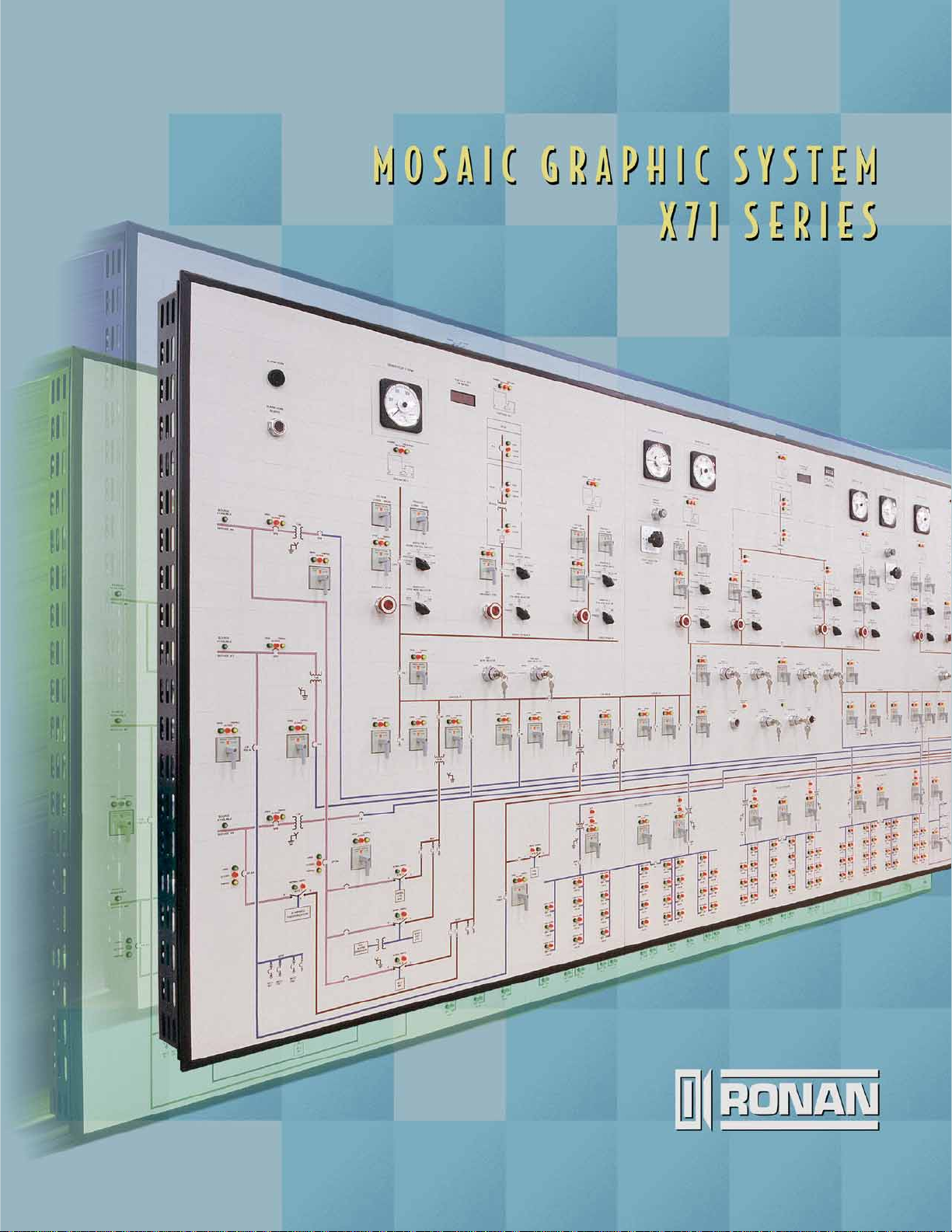
The Ronan Series X71 Mosaic Graphic System is ideally suited for
the graphic display of industrial processes, power distribution networks,
security and fire alarm of buildings in aerial layout, airport runways and
luggage handling facilities, etc. The graphic layout generally includes
status or alarm LED indication, selector and push-button switches,
analog meters, digital and bargraph readouts, annunciators and time
clocks, etc.
The X71 Mosaic Graphic is best suited where applications require
frequent modifications due to plant expansions or process changes.
The surface of the mosaic tiles is silk-screened or engraved with the
customized layout depicting the process or facilities. The panel or wall
mounted graphic provides for a very functional and aesthetically
Plant Security & Fire Alarm Systems
HVAC Systems
Power Plants & Switchyards
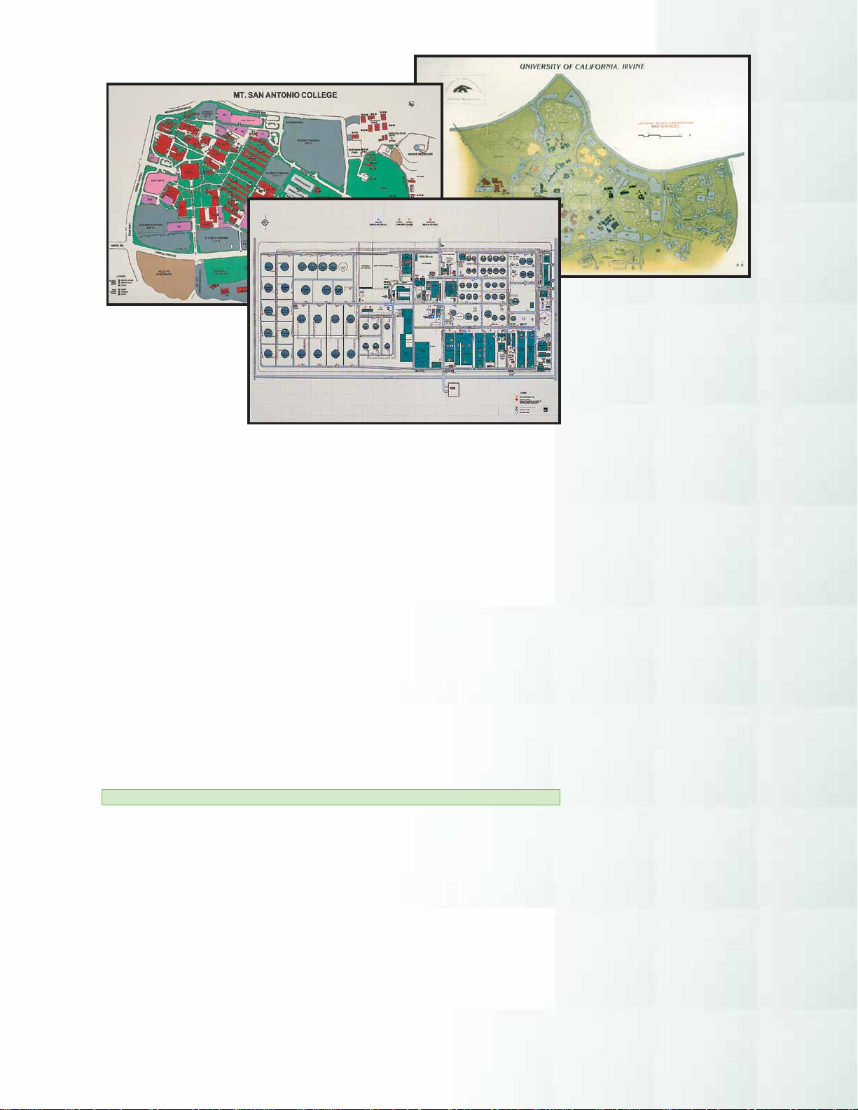
Geographical Maps
Industrial Process Plants
Water Treatment & Power Plants
Power Distribution Networks
Information Systems & Data Highway
Gas Distribution Plants
pleasing process or facility annunciator/control system.
Mass Transit & Subway Systems
FEATURES
•High Strength Structural
Mounting Frame
•1″ (25.40 mm) and 2″ (50.80 mm)
Square Tiles
•Multicolor Split Indicators
2
•Conventional and Serial Input
Annunciators
•Smaller and Larger Depth Frames
Available
•Large Number of Colors Available
•Through or Behind Tile Indicators
•Lamp Displays
•Glass Filled Nylon Grid for
Maximum Strength
•Translucent Tiles for Rear-Lit Symbols
•Multifunction Switches and
Push Buttons
•Custom Equipment Integration
•Multicolor Process Lines Outlined
and Non-Outlined
•UL Listed
Three Dimensional Plant Layouts
Airport Luggage Handling Facilities
Material Handling & Conveyor Systems
Emergency Power Switching Systems
Traffic Control Metering
Page 3
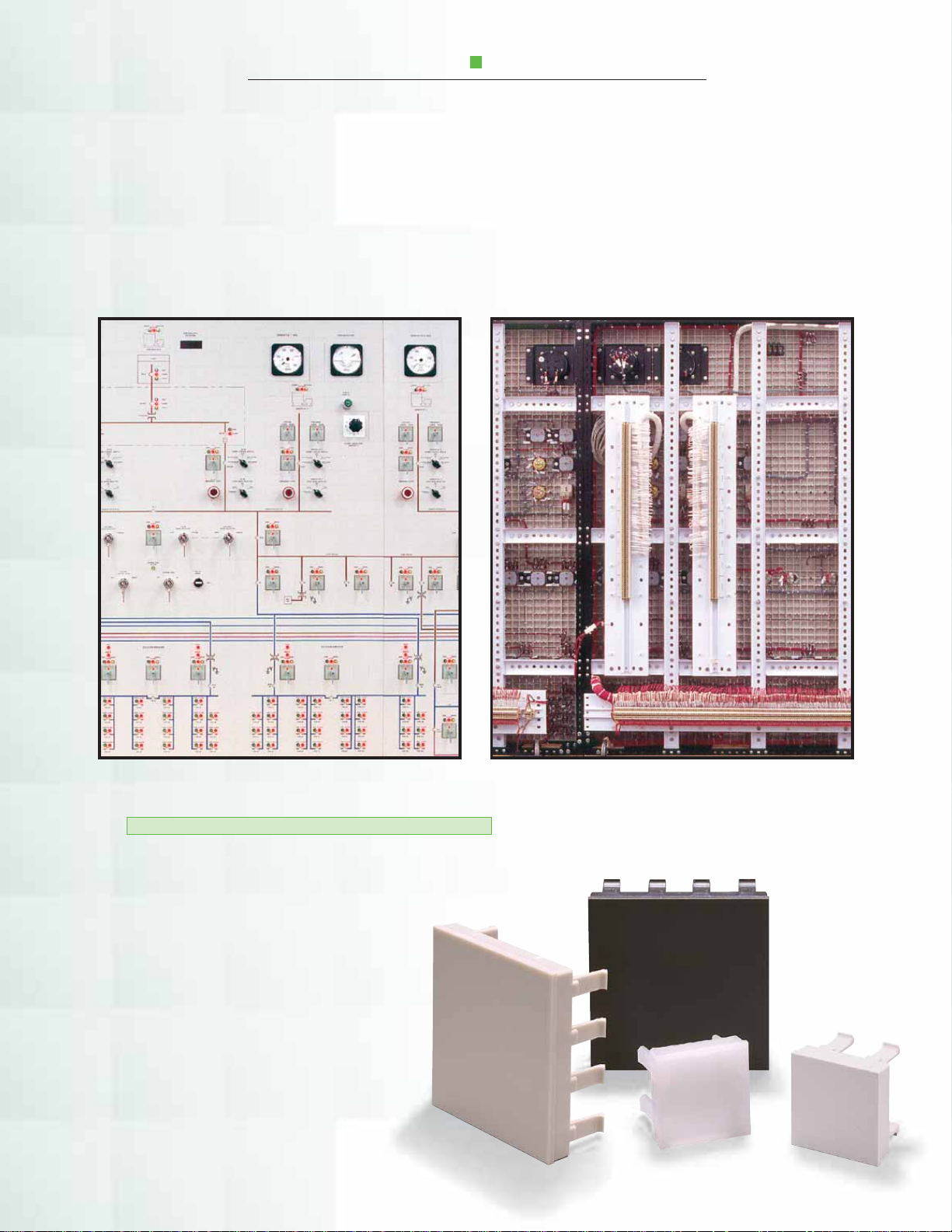
MOSAIC TILES AND GRID
The grid and tile construction allows the highest
flexibility in regard to overall sizing, modification of
display layout and addition or omission of indicators,
control devices, and equipment without the use of
special tools or training. The tile assembly is customized to the specific requirement of an application in
multiples of a single tile size increment. The grid is
supported from the peripheral framework and cross
beam structure for maximum stability. The graphic
assembly is installed through a single panel cutout of
the control panel and secured with clamps provided.
Front View Rear View
TILES AND GRID MATRIX
The high precision 12″ x 12″ (304.80 mm x 304.80 mm)
standard grid is molded from glass-filled nylon 6/6 flameretardant 94V-0 material. The grid is cut in 1″ (25.40 mm)
increments and is assembled to meet size
requirements.
The tiles are molded from polycarbonate
flame-retardant 94V-0 material and are selfextinguishing, highly resistant to ultraviolet
rays, and meet ASTMD648 heat deflection
temperatures of 280° F. The tiles are available
in 1″ x 1″(25.40 mm x 25.40 mm) and
2″ x 2″ (50.80 mm x 50.80 mm). The two
sizes may be mixed on the same grid, with 2″ x 2″
(50.80 mm x 50.80 mm) tiles suitable for larger graphics.
3
Page 4
AUTO RUNNING
MANUAL
M
1600AF
1600AT
ARCHITECTURAL
Mechanical Closet
3
2
1
.1
MOSAIC
200A
PU-801
HI-LO
PRESSURE
GRAPHIC LAYOUT
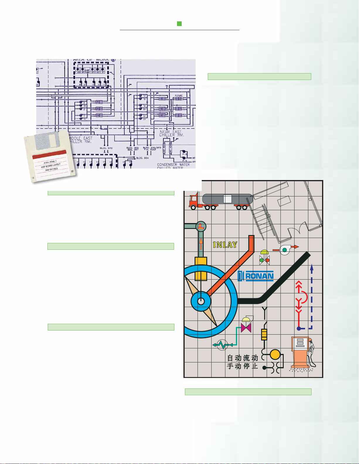
LINES
The process line width should be selected based
on the graphic’s overall size and is available outlined
or not outlined (solid). Care should be taken in the
selection of color for contrast in text/process outlines.
DOCUMENTATION
The graphic layout is best transferred via
computer file. If not available, an actual size
drawing will reduce customer approval time
for layouts. Ronan factory personnel will
verify compliance with tile and grid layout
requirements and optional mounting facilities
for special equipment. The customer is requested to select the color for lines, symbols,
and tile background from the color chart.
(See back page)
4
TEXT/LETTERING
The recommended standard lettering style is
gothic, with many other computer generated styles
available. The letters should be sized for easy readability by the operator. Recommended sizes are from
7/16″ (11.11 mm) to 1/2″ (12.70 mm) high. The lettering is centered on symbols or tiles with adjustments
to minimize screening across tile separation.
SYMBOLS AND CUSTOM LOGO
A large number of standard symbols is available.
These can be sized to fit on a single tile or a number
of tiles and placed symmetrically for the best visual
appearance. The standard symbols are available from
Ronan on Auto CAD files to simplify the graphic
layout for the customer. Custom symbols may be generated for specific applications, including customer’s
logo in the graphic layout.
PROTECTIVE COATING
The final graphic display is coated with a nonglare UV resistant acrylic spray for a long-lasting, soil
resistant appearance. The protective coating allows for
cleaning with mild cleaners or soap solution.
Page 5
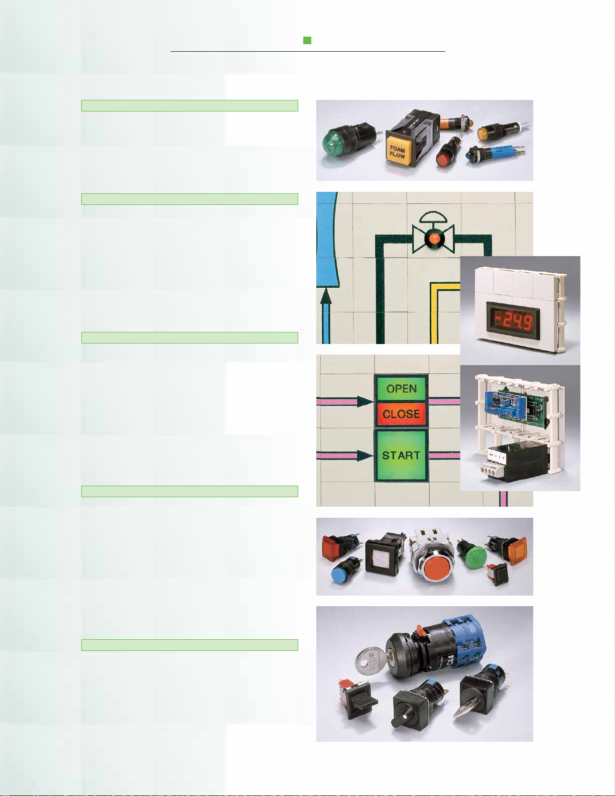
LIGHTS AND SWITCHES
INDICATOR LIGHTS
All indicator lights utilized are LED type (Light
Emitting Diodes) with current limiting to provide
greater than 100,000 hours of life. The indicators are
available in through-the-tile or behind-the-tile versions.
THROUGH THE TILE
Typical through-the-tile LED indicators are available
in various diameters and light intensity. The size of the
indicators should be based on the size and density of
the graphic. Single or dual color indicators available.
If the customer does not state a preference, Ronan
will select the appropriate type, based on the client’s
application.
BEHIND THE TILE
The Ronan Series X71 LED indicator is a 1″ x 1″
(25.40 mm x 25.40 mm) assembly which attaches to
the grid from the rear behind a translucent tile. The
translucent tile is typically screened with a process
symbol or outline. The X71s are available in single or
multiple colors (up to 3 colors), e.g. green, red or
amber. The three colors are typical for motor or valve
status indication.
PUSH BUTTONS
Push buttons are available in many different sizes
and may occupy a single tile or multiple tiles. The
number of poles and contact ratings are application
based and must be specified by the customer.
Illuminated (LED type) and non-illuminated push
buttons are available with round, square, and rectangular buttons. Momentary or ON/OFF functions with
single or multi-poles are available.
SWITCHES
Proper selection of switches should be made by the
customer based on the application, taking into consideration power requirements, number of poles,
positions (maintain or spring return), actuator (key or
handle), and size. Ronan’s product specialists are
available for technical support.
5
Page 6
ANNUNCIATION AND PROCESS PARAMETER
DISPLAYS
SERIAL INPUT ANNUNCIATORS
The most suitable approach for a larger number
ANNUNCIATORS
The X71 graphic may include conventional
window annunciators mounted into the grid with
special mounting facilities. Due to the annunciators’
inherent heavy weight, there are limitations to their
size. For applications where large numbers of
windows are required, a combination of lamp cabinet,
incandescent or LED type, with remote annunciator
logic is recommended.
of windows or indicators is to utilize the Ronan X110
Serial Input Annunciator Controller driven from a host
such as a PLC, Ronan X120 Field Multiplexer, or an
X500E Sequence of Events Recorder. Each X110
controller provides for 48 outputs with individually
selectable alarm sequence per output. The X110s are
typically mounted in the graphic enclosure or integral
to the rear of the graphic assembly.
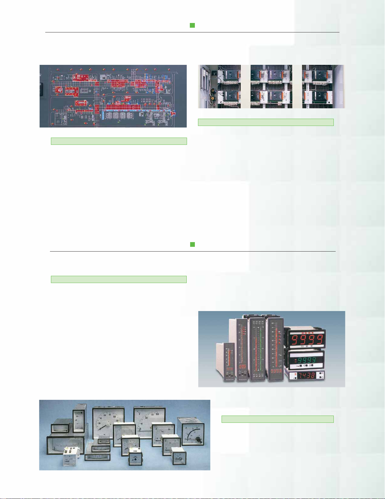
DIGITAL/ANALOG METERS AND DISPLAYS
DIGITAL DISPLAYS/BARGRAPHS
Digital Indicators are available in many sizes and
should be selected based on the application. Typical
requirements are AC or DC currents and voltage,
Watt and VAR, frequency, time clock, and process
loop indicators. Typical indicators come with different
size LEDs or LCDs, with any number of digits as
specified by the customer. Digital Indicators typically
span multiple tiles with Ronan providing custom
mounting facilities.
Bargraphs can be utilized as process value indica-
tors with 4-20 mA input and are available with single
or dual channel LED display, with digital indicators
optionally. The bargraphs may be horizontally or
vertically mounted onto Ronan supplied plates.
6
ANALOG DISPLAYS
Analog Meters for specific custom requirements can be supplied. Selection should be
made by the customer with Ronan to supply
special mounting plates sized to the meter’s
dimensions.
Page 7

SPECIFICATIONS
MECHANICAL
The X71 Mosaic Graphic System is assembled from
12″ x 12″(304.80 mm x 304.80 mm) reinforced fiberglass matrix grids to the customer’s specified size. The
assembled grids are mounted into a heavy steel frame
with cross beam support on each corner of each 12″
(304.80 mm) matrix grid. The steel frame is selected
from the two available depths based on the overall size
of the graphic. The accurate panel cutout dimensions
are supplied with the process layout approval drawings
to allow preparation of the control or display panel.
MOUNTING
The X71 graphic assembly is fed through the panel
cutout from the front of the panel and clamped from
the rear with the furnished removable clamp assemblies. The maximum panel thickness allowed with the
standard clamping assemblies is 1″(25.40 mm).
Clearance behind the graphic is based on the depth
of the custom equipment mounted in the graphic as
well as optional termination facilities, connectors, or
serial input annunciators.
3.65"
A Overall
B Cutout
B
Cutout
A
Overall
H Graphic Width
A Overall = Graphic H or W x .0015″ (.0381 mm) + Graphic H or W + 1.50″ (38.10 mm)
B
Cutout
A
Overall
B Cutout = A Overall – .62″ (15.75 mm)
A Overall
B Cutout
(92.71 mm)
H
Graphic
Height
(143.51 mm)
H
Graphic
Height
5.65"
A
A
ELECTRICAL
The indicators, control switches, push buttons,
parameter displays, or other equipment required may
be factory wired to terminals mounted to the rear of
the mechanical structure. The indicators and/or
window type lamp cabinets may be controlled from
conventional solid state alarm logic or X110 Serial
Input Annunciator Controller(s). The X110 may be
integral mounted to the rear of the graphic and factory
wired to the indicators. Optionally, Ronan may provide
multiconductor cables wired to the indicators in the
graphic, and multi-pin connectors for interface to the
remote mounted X110 controllers.
SPECIAL ENCLOSURES
The X71 graphic may be mounted into custom
fabricated enclosures. The enclosures are manufactured
from stainless steel or from cold-rolled steel and
painted to customer specified color. They are sized to
accommodate the graphic, termination facilities and/
or serial input annunciator controllers.
.38" (9.65 mm)
Maximum Thickness
Mounting Panel
Frame
Extrusion
Tile
Grid
H Graphic Width
Mounting Clamp Assembly
Maximum 12.00" (304.80 mm)
Spacing
Detail A
7
Page 8

ORDERING INFORMATION
Color and number selector for symbols and flow lines
100
103
104
106
108
109
114
115
116
117
118
161
162
163
119
120
121
122
123
127
124
125
126
129
130
131
164
165
132
133
134
135
137
138
166
136
139
140
141
142
143
146
144
145
147
150
152
153
154
155
159
160
Complete the information below when
ordering your X71 Mosaic Graphic
Layout Size:
Height ______ Inches ______ (mm)
Width ______ Inches ______ (mm)
Tile Size:
❏ 1″ x 1″ (25.40 mm x 25.40 mm)
❑ 2″ x 2″ (50.80 mm x 50.80 mm)
Tile Color:
❑ Beige ❑ White
❑ Light Gray ❑ Charcoal Gray
Process Layout:
❑ Sketch ❑ Drawing ❑ Auto Cad
❑ 5 Colors or Less ❑ Additional Colors
Indicators:
❑ Through Tile, Number of LEDs _________
❑ Behind Tile, Number of Assemblies ____
(Standard Voltage 24 Vdc, Current 20 mA.
Other Lamp Voltages Available)
Number of Clocks _____________________
Number of Lamp Cabinets _____ Size ______
Number of Annunciators _____ Size _______
❑ Serial Input Annunciator Controller X110
(48 Outputs per Unit)
❑ Terminals: Weidmueller SAK2.5
❑ Terminals with Dual Gating Diodes:
Weidmueller DK4D (Required for Lamp Test)
❑ Analog Display, Model No. ____________
❑ Bargraphs, Model No. _______________
❑ Digital Display, Model No. _____________
Push-Button and Rotary Switches:
Number of Switches ___________________
Number of Poles ______________________
Number of Positions ___________________
Voltage _____ Current Requirement _______
X71 Rev.1 08/01
THREE–YEAR WARRANTY
Ronan warrants equipment of its own manufacture to be free from defects in material and workmanship,
under normal conditions of use and service, and will repair or replace any component found to be defective, on its
return, transportation charges prepaid, within three (3) years of its original purchase. This warranty carries no
liability, either expressed or implied, beyond our obligations to replace the unit which carries the warranty.
RONAN ENGINEERING COMPANY
Display Products Division
21200 Oxnard Street, Woodland Hills, CA 91367 U.S.A. • 800-327-6626 • Fax 818-992-6435
1 Tilley Road, Crowther Industrial Estate, Washington, Tyne & Wear U.K., NE38 OAE • 191-416-1689 • Fax 191-416-5856
32 Bermondsey Road, Toronto, Ontario, Canada M4B 1Z5 • 416-752-0310 • Fax 416-752-8072
http://www.ronan.com E-Mail: sales@ronan.com
Printed in U.S.A.
 Loading...