

Page 1
ISO 9001
REGISTERED
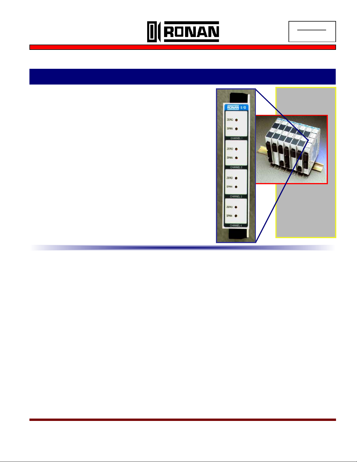
4-20 mA Signal Repeater/Isolator Transmitters - DIN Rail Mounting
X54-3224 Four (4) Channel Input Loop Powered I to I Isolator (mA transmitter)
♦ High Density Four (4) Channel Packaging
♦ Input Loop Powered
♦ Low Input Loop Burden (<6 vdc @ 250 ohm load)
♦ Ideal for High Density I-to-I Isolator Requirements
♦ Max. Output Loop Load = 500 ohms
♦ Full Input/Output/Power and Channel Isolation
♦ Standard 35 mm DIN Rail Mounting
DESCRIPTION: The X54-3224 is a four channel current-to-
current repeater/isolator transmitter powered by the input 4-20 mA current loops. Features include: two piece plug-in connectors for easy wiring and maintenance; full 1000 vac isolation; and front panel access to
ZERO and SPAN Adjustments. Dual output options per channel allows for matching load requirements and Input loop burden. RFI protection, wide operating temperature, and high accuracy are standard
features.
SPECIFICATIONS:
Inputs:
4-20 mA (input loop burden is <6 vdc drop+(IloadXRload))
Outputs:
Output #1 = 4-20 mA into 0 to 99 ohm load (3 vdc)
Output #2 = 4-20 mA into 100 to 500 ohm load (10 vdc)
Span Adjustment:
Front-accessible, multi-turn, infinite resolution potentiometer
permits minimum +/- 5% adjustment.
Zero Adjustment:
Front-accessible, multi-turn, infinite resolution potentiometer
permits minimum +/- 5% adjustment
Calibrated Accuracy: +/- 0.1% of span
Isolation: 1,000 vac between channels, input and output.
Common Mode Rejection: > 120 dB, DC at 60 Hz.
Common Mode Voltage:
1000 volts peak AC maximum without damage.
Ambient Temperature Coefficient:
Ambient temperature range: 32 to 158 F (0 to 70 C).
Gain: < +/- 0.01 %/ F.
Zero: < +/- 0.005 %/ F.
Ambient Temperature Range:
Operating: -20 to 158 F (-25 to 70 C).
Storage: -40 to 158 F ( -40 to 70 C).
Radio Frequency Effects:
< 0.4 mV (referred to input) + 0.2% of span (referred to output) when exposed to 5W transmitter with frequency range
20-460 MHz at a distance of meter.
Terminals:
High temperature polyester type, wire size 12 AWG max., 10
A max., 300 V max.
A Family of
Products!!!
Transmitters
Alarm Trips
I/I Isolators
Page 1 of 2
Specifications apply at 23 +/- 2°C (74 +/- 2°F) unless otherwise specified, and are subject to change without notice,
Ronan Engineering Company
Ph: 800-327-6626 Fax: 818-992-6435 E-mail: sales@ronan.com Web: www.ronan.com
Rev. 0
Page 2
X54-3224 Four (4) Channel Input Loop Powered I to I Isolator (continued)
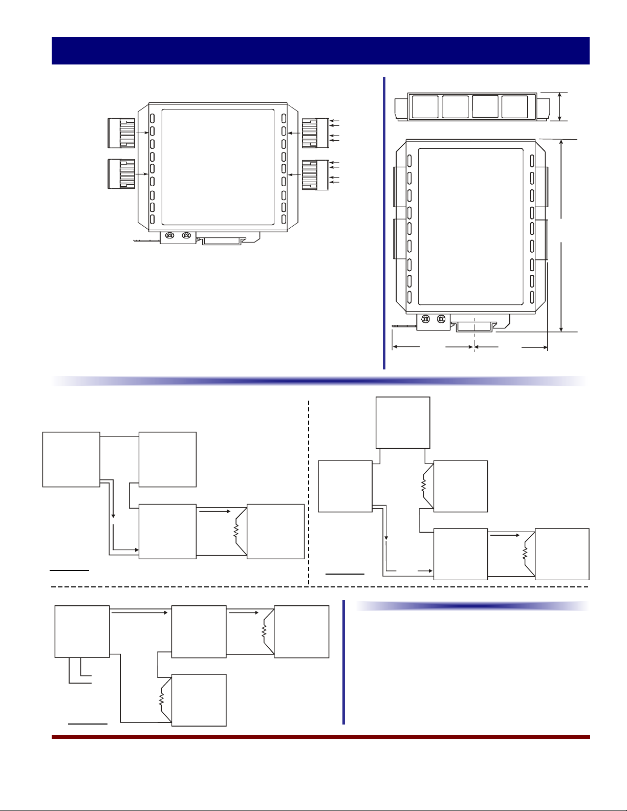
TERMINAL ARRANGEMENT:
Outputs
Ch1
Ch2
Ch3
Ch4
J2*J2*
+
1
-
2
NC
3
+
4
-
5
NC
6
J4*
+
1
-
2
NC
3
+
4
-
5
NC
6
*
1.) Plug-in connector design simplifies installation and
maintenance.
2.) Use up to 12 awg wiring.
3.) When inserted, case back cover provides a mechanical
cover for connector screws (as required by European
standards).
J1*
J3*
1
2
3
4
5
6
1
2
3
4
5
6
4-20 mA
Inputs
+
Ch1
-
+
Ch2
-
+
Ch3
-
+
Ch4
-
MECHANICAL DETAIL:
2.47”
62.7mm
C
DIN Rail
2.23”
54.6mm
L
0.850”
21.6mm
5.80”
147.3mm
TYPICAL WIRING EXAMPLES:
+
PLC Powered
Sig
J1-2
- +
4-20 mA
+ -
J1-1
4-20 mA
Loop
J2-1
4-20 mA
X54-3224
J2-2
J1-1
+ +
X54-3224
- -
J1-2
+
Load
#1
Loop Powered
2W
Trans mitter
Example #1
4 Wire
Tran smit ter
with Powered
Output L oop
+
-
24 VDC
Power
+
-
+
-
J2-1
4-20 mA
J2-2
Load
#2
+
Load
#2
-
Loop Powered
2W
Tran smitt er
Example #2
24 VDC
Pwr
+ -
+
-
4-20 mA
-
Load
#1
+
J1-2
- +
X54-3224
+ -
J1-1
J2-1
4-20 mA
J2-2
+
Load
#2
-
ORDERING INFORMATION:
X54 -3224
Accessories:
D2-35X7.5 35mm X 7.5mm “U” style rail
Example #3
Page 2 of 2
-
Ronan Engineering Company
Ph: 800-327-6626 Fax: 818-992-6435 E-mail: sales@ronan.com Web: www.ronan.com
Rev. 0
 Loading...