

Page 1

X500/X1000 Product Family
Model X501NET
Document Number X1000-3104-IOM
Manual Rev. 1.0
X501 NET
SYSTEM CONFIGURATION MANUAL
2008
RONAN ENGINEERING COMPANY
21200 Oxnard Street
Woodland Hills, CA 91367
http://www.ronan.com
.
© Copyright 2008 Ronan Engineering Company. All rights reserved. This document may not be
reproduced or transmitted in any form, electronic or mechanical, including photocopying,
recording, storing in an information retrieval system, or translating, in whole or part, without the
prior written permission of Ronan Engineering Company.
Page 2

REVISION LOG
Rev # Description Date By Eng Appr QA
0.1 First rough draft for engineering review 1/11/2008 Tobol
0.2 Second draft for engineering review (all sections
complete)
1.0 First release version 1/23/2008 Tobol
1/15/2008 Tobol
X501NET Hardware Configuration Manual © 2008 Ronan Engineering Company
Page 3

Table of Contents
Table of Contents
CHAPTER 1 – INTRODUCTION.............................................................................................................................1
1.1 OVERVIEW...........................................................................................................................................................1
1.1.1 X501NET.....................................................................................................................................................1
1.1.2 Master Station.............................................................................................................................................2
1.1.3 Database Server..........................................................................................................................................2
1.1.4 User Workstation ........................................................................................................................................2
1.1.5 Window Annunciator...................................................................................................................................2
1.1.6 Network Connection (LAN/WAN)...............................................................................................................2
1.2 GETTING STARTED...............................................................................................................................................2
1.3 X501 HARDWARE DESCRIPTION..........................................................................................................................3
1.4 GLOSSARY...........................................................................................................................................................3
1.5 DOCUMENTATION CONVENTIONS ........................................................................................................................4
CHAPTER 2 – INTERFACE.....................................................................................................................................6
2.1 COMMON ELEMENTS ...........................................................................................................................................6
2.1.1 Common Buttons.........................................................................................................................................6
2.1.2 Results Pages..............................................................................................................................................7
2.1.2.1 Success Page..................................................................................................................................................... 7
2.1.2.2 No Rights Page.................................................................................................................................................. 8
2.2 MAIN MENU PAGE..................................................................................................................................................8
2.2.1 Main Menu Page Buttons..........................................................................................................................9
2.2.2 Status and Reports.......................................................................................................................................9
2.2.2.1 Points Status Link............................................................................................................................................. 9
2.2.2.2 Events History Link..........................................................................................................................................9
2.2.3 Configuration............................................................................................................................................10
2.2.3.1 General Configuration Link.......................................................................................................................... 10
2.2.3.2 Input Cards Link..............................................................................................................................................10
2.2.3.3 Points Configuration Link............................................................................................................................. 10
2.2.3.4 Network Link ....................................................................................................................................................10
2.2.3.5 IEC 60870-5-104 Link...................................................................................................................................... 10
2.2.3.6 X110 Connection Configuration Link......................................................................................................... 10
2.2.3.7 Users Link......................................................................................................................................................... 11
2.2.3.8 User Notes Link............................................................................................................................................11
2.2.3.9 Configuration File Link..................................................................................................................................11
2.3 LOGIN PAGE.......................................................................................................................................................11
2.3.1 Login Page Buttons................................................................................................................................12
2.3.2 User ID and Password............................................................................................................................12
2.4 POINT STATUS PAGE ..........................................................................................................................................12
2.4.1 Point Status Page Buttons.................................................................................................................13
2.4.2 Point List...................................................................................................................................................14
2.4.2.1 Point .................................................................................................................................................................. 14
2.4.2.2 LogAddr............................................................................................................................................................ 14
2.4.2.3 Tag.....................................................................................................................................................................14
2.4.2.4 State Legend.................................................................................................................................................... 14
2.4.2.5 Polarity..............................................................................................................................................................14
2.5 EVENT HISTORY PAGE ........................................................................................................................................14
2.5.1 Event History Page Buttons...............................................................................................................15
2.5.2 History.......................................................................................................................................................16
2.5.2.1 Event ID.............................................................................................................................................................16
2.5.2.2 mm/dd/yyyy ..................................................................................................................................................... 16
2.5.2.3 hh:mm:ss.ms................................................................................................................................................... 16
2.5.2.4 Addr/Msg.......................................................................................................................................................... 16
2.5.2.5 Key..................................................................................................................................................................... 16
X501NET System Configuration Manual © 2008 Ronan Engineering Company i
Page 4

Table of Contents
2.5.2.6 Tag/Message.................................................................................................................................................... 17
2.5.2.7 Legend/Description .......................................................................................................................................17
2.6 GENERAL CONFIGURATION PAGE........................................................................................................................17
2.6.1 General Configuration page Buttons............................................................................................18
2.6.2 Basic Multiplexer Configuration...............................................................................................................18
2.6.2.1 Mux ID (Physical Address) Field.................................................................................................................. 18
2.6.2.2 Keep Logical=Physical Check Box............................................................................................................... 18
2.6.2.3 Mux Node Logical Address Field.................................................................................................................19
2.6.2.4 All Points Same Logical Address Check Box............................................................................................ 19
2.6.2.5 Points Display Offset Field ........................................................................................................................... 19
2.6.2.6 Mux Tag Field......................................................................................................................... .......................... 19
2.6.3 Time Configuration...................................................................................................................................19
2.6.3.1 NTP Servers Field............................................................................................................................................ 19
2.6.3.2 Time Zone Field ............................................................................................................................................... 20
2.6.3.3 NTP Acquisition Interval Fields.................................................................................................................... 20
2.6.3.4 NTP Switch Timeout Field............................................................................................................................. 20
2.6.3.5 Preferred Time Source Field......................................................................................................................... 20
2.6.3.6 IRIG-B mode Field ...........................................................................................................................................21
2.7 INPUT CARDS PAGE............................................................................................................................................21
2.7.1 Input Cards Page Buttons ...................................................................................................................22
2.7.2 Card Configuration...................................................................................................................................23
2.7.2.1 Global Test Interval Field............................................................................................................................... 23
2.7.2.2 Card Field..........................................................................................................................................................23
2.7.2.3 Enabled Field.................................................................................................................................................... 23
2.7.2.4 Model Field........................................................................................................................................................ 23
2.7.2.5 Status Field....................................................................................................................................................... 23
2.7.2.6 Test Field........................................................................................................................................................... 24
2.7.2.7 Interval Field.....................................................................................................................................................24
2.8 POINTS CONFIGURATION PAGE...........................................................................................................................24
2.8.1 Points Configuration Page Buttons..............................................................................................25
2.8.2 Point Parameters......................................................................................................................................26
2.8.2.1 Physical Address Field ..................................................................................................................................26
2.8.2.2 Current State Field.......................................................................................................................................... 26
2.8.2.3 Logical Address Field ....................................................................................................................................26
2.8.2.4 Tag Field............................................................................................................................................................ 26
2.8.2.5 Alarm Legend Field......................................................................................................................................... 27
2.8.2.6 Normal Legend Field ......................................................................................................................................27
2.8.2.7 Toggle Legend Field....................................................................................................................................... 27
2.8.2.8 Polarity Field..................................................................................................................................................... 27
2.8.2.9 In Service Field................................................................................................................................................. 27
2.8.2.10 Filter Type Field............................................................................................................................................. 27
2.8.2.10.1 Consecutive Filter..................................................................................................................................... 27
2.8.2.10.2 Integrating Filter....................................................................................................................................... 28
2.8.2.10.3 Filter Time Constants................................................................................................................................28
2.8.2.11 Alarm Time Constant Field.........................................................................................................................30
2.8.2.12 Normal Time Constant Field....................................................................................................................... 30
2.8.2.13 Debounce Time Constant Field..................................................................................................................30
2.8.2.14 Toggling Interval [ms] Field........................................................................................................................ 30
2.8.2.15 Toggling Trips Field...................................................................................................................................... 30
2.9 NETWORK PAGE...................................................................................................................................................30
2.9.1 Network page Buttons............................................................................................................................31
2.9.2 DHCP........................................................................................................................................................32
2.9.3 Static Address............................................................................................................................................32
2.9.3.1 IP Address Field...............................................................................................................................................32
2.9.3.2 IP Network Mask Field......................................................................................................................... ........... 32
2.9.3.3 Default Gateway Field .................................................................................................................................... 33
2.9.3.4 Name Server Field........................................................................................................................................... 33
2.10 IEC 60870-5-104 PAGE.............................................................................................................................33
2.10.1 IEC 60870-5-104 page Buttons........................................................................................................34
X501NET System Configuration Manual © 2008 Ronan Engineering Company ii
Page 5

Table of Contents
2.10.2 Parameters..............................................................................................................................................35
2.10.2.1 Protocol/Disabled Field................................................................................................................................35
2.10.2.2 Device ID Field ...............................................................................................................................................35
2.10.2.3 Device Name Field......................................................................................................................................... 35
2.10.2.4 Device Password Field.................................................................................................................................35
2.10.2.5 IEC60870 Servers Field................................................................................................................................ 35
2.10.2.6 TCP Port Field ................................................................................................................................................36
2.10.2.7 Initial Discovery Port Field..........................................................................................................................36
2.10.2.8 Common ASDU Address Field...................................................................................................................36
2.10.2.9 Originator Address Field............................................................................................................................. 36
2.10.2.10 Confirmation Timeout Field...................................................................................................................... 36
2.10.2.11 Termination Timeout Field........................................................................................................................ 36
2.10.2.12 Window Size (K) Field................................................................................................................................. 36
2.10.2.13 Window Size (W) Field................................................................................................................................ 36
2.10.2.14 Timeout T0 Field.......................................................................................................................................... 37
2.10.2.15 Timeout T1 Field.......................................................................................................................................... 37
2.10.2.16 Timeout T2 Field.......................................................................................................................................... 37
2.10.2.17 Timeout T3 Field.......................................................................................................................................... 37
2.10.2.18 Status Point Address Field.......................................................................................................................37
2.10.2.19 Transmit Queue Size Field........................................................................................................................37
2.10.2.20 Sync on TimeSync Command Field........................................................................................................ 37
2.11 X110 CONNECTION CONFIGURATION PAGE.......................................................................................................37
2.11.1 X110 Connection Configuration Page Buttons........................................................................38
2.11.2 Connections.............................................................................................................................................39
2.11.2.1 Node Field .......................................................................................................................................................39
2.11.2.2 Protocol Field................................................................................................................................................. 39
2.11.2.3 IP Address Field.............................................................................................................................................39
2.11.2.4 Port Field .........................................................................................................................................................39
2.12 USERS PAGE.....................................................................................................................................................39
2.12.1 Users Page Buttons ..............................................................................................................................40
2.12.2 User Names and Passwords....................................................................................................................41
2.12.3 User Rights..............................................................................................................................................41
2.12.3.1 Administrator................................................................................................................................................... 41
2.12.3.2 Operator........................................................................................................................................................... 41
2.12.3.3 Guest................................................................................................................................................................ 41
2.13 USER NOTES PAGE............................................................................................................................................41
2.13.1 User Notes Page Buttons....................................................................................................................42
2.14 CONFIGURATION FILE PAGE.............................................................................................................................43
2.14.1 Configuration File Page Buttons.................................................................................................44
2.14.2 Configuration File Content.....................................................................................................................44
CHAPTER 3 – INITIAL CONFIGURATION.......................................................................................................45
3.1 FIRST LOGIN ......................................................................................................................................................45
3.2 NETWORK CONFIGURATION...............................................................................................................................45
3.3 USER CONFIGURATION ......................................................................................................................................45
3.4 GENERAL CONFIGURATION................................................................................................................................46
3.5 CARD AND POINT CONFIGURATION ...................................................................................................................46
3.6 IEC 60870 CONFIGURATION .............................................................................................................................46
3.7 X110 CONFIGURATION .....................................................................................................................................46
CHAPTER 4 – PROCEDURES...............................................................................................................................47
4.1 LOGGING IN.......................................................................................................................................................47
4.2 VIEWING POINT STATE ......................................................................................................................................47
4.3 VIEWING EVENT HISTORY .................................................................................................................................47
4.4 DISABLING/ENABLING A POINT .........................................................................................................................47
4.5 ADJUSTING POINT PARAMETERS........................................................................................................................47
4.6 ADDING/REMOVING MULTIPLEXER CARDS .......................................................................................................48
4.7 ADDING/REMOVING USERS ...............................................................................................................................48
X501NET System Configuration Manual © 2008 Ronan Engineering Company iii
Page 6

Table of Contents
CHAPTER 5 – TROUBLESHOOTING CONFIGURATION PROBLEMS.......................................................49
5.1 CONFLICTS WITH DHCP SERVER......................................................................................................................49
5.2 NETWORK ADDRESS CONFLICTS........................................................................................................................49
5.3 NETWORK TRAFFIC ISSUES................................................................................................................................49
5.4 LOST PASSWORD ...............................................................................................................................................49
APPENDIX A – SAMPLE CONFIGURATION FILE..........................................................................................50
X501NET System Configuration Manual © 2008 Ronan Engineering Company iv
Page 7
Chapter 1 - Introduction
CHAPTER 1 – INTRODUCTION
The X501NET is a network device. It has no local display or keyboard. It is configured through
the same local area network (LAN) connection that it uses to pass the data it collects.
The X501NET has a built-in web server and uses the HTTP protocol for configuration. No
special software is required. Any computer attached to the same LAN as the X501NET can use a
JavaScript enabled web browser (e.g. Internet Explorer, Mozilla, FireFox, etc) to configure the
X501NET.
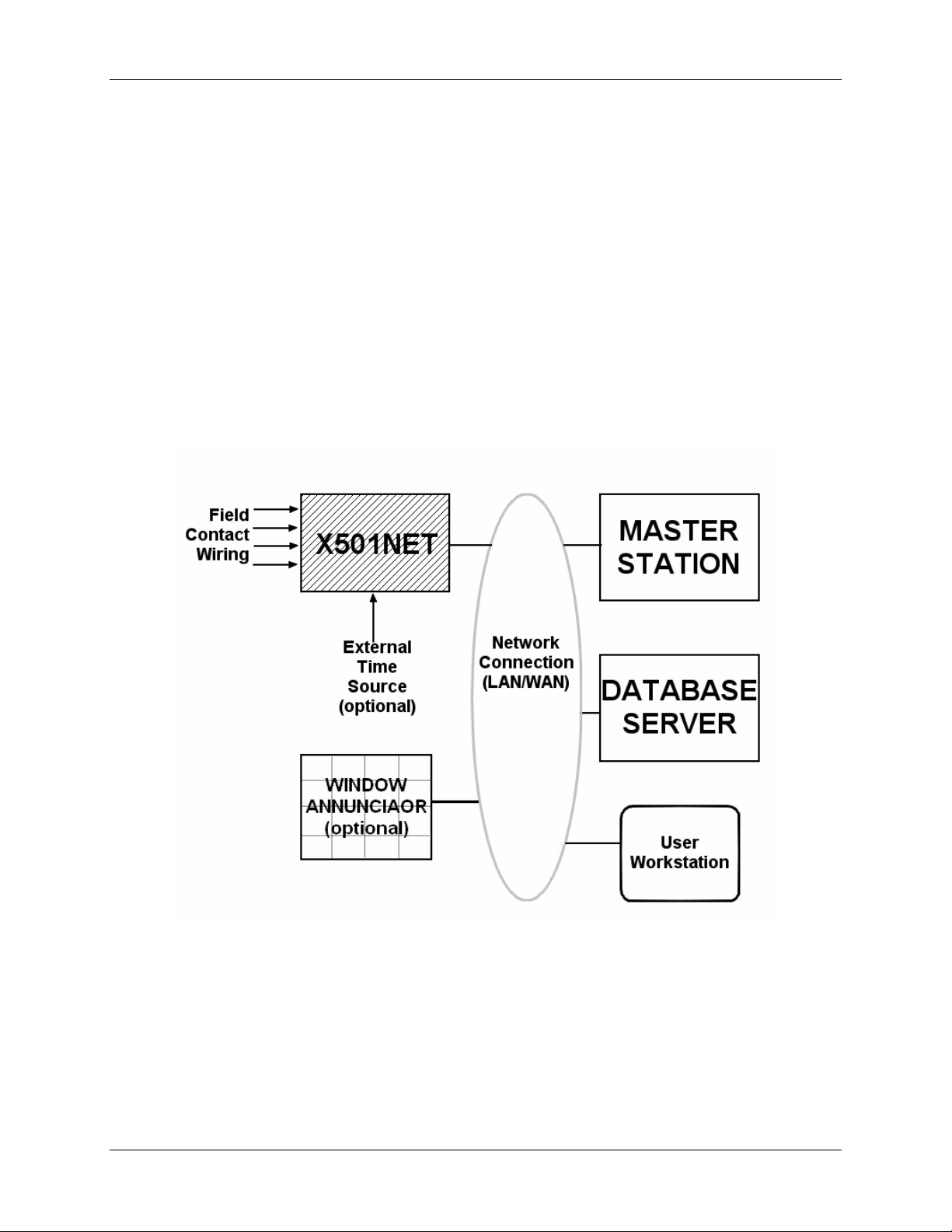
1.1 Overview
The X501NET is a component of Ronan’s Sequence of events Recorder (SER) system. An SER
is an electronic system which monitors external inputs and records the time and sequence of the
changes of the inputs.
SER Functional Diagram
1.1.1 X501NET
The X501NET Multiplexers is an event acquisition device. It:
• monitors field contacts,
• detects changes in signals,
• time-stamps the signals changes as events,
X501NET System Configuration Manual © 2008 Ronan Engineering Company 1
Page 8

Chapter 1 - Introduction
• maintains a copy of the most recent 8000 events,
• sends the events to master station(s),
• optionally sends the events to window annunciator(s), and
1
• optionally generate IRIG-B
One or more event acquisition device(s) are always part of an SER system.
1.1.2 Master Station
The master station(s):
• receives events
2
from the event acquisition devices (e.g. X501NET),
• stores the events on the database server, and
• provides a user interface to the SER system.
1.1.3 Database Server
The database server maintains the event history. It is written to by the master station(s) can be
accessed by the master station(s) and user work station(s).
1.1.4 User Workstation
User workstations allow plant personnel access to the event status and history. They also provide
a interface to configure the X501NET(s),
1.1.5 Window Annunciator
A window annunciator (such as the Ronan X110) is a display device that shows events and
process status by lighting individual windows. A window annunciator provides plant operators
with an instantly identifiable view of plant status and can save critical seconds when problems
occur.
1.1.6 Network Connection (LAN/WAN)
The network connects all of the parts of the SER system. Logically, the network is always the
same, it simply passed messages between the components of the SER system. In physical
implementation, the network is the most variable part of the SER system. It can be as simple a
single LAN or as complex as a set of LANs interconnected by the both public (e.g. world wide
web) and private data networks.
1.2 Getting Started
To get started using the X501NET configuration program you need a computer with web
3
browser
1
IRIG-B120.
2
This function is called an Event Producer by IEC 60870.
attached to the same LAN as the X501NET. Put the address4 of the X501NET that you
X501NET System Configuration Manual © 2008 Ronan Engineering Company 2
Page 9

Chapter 1 - Introduction
wish to configure into the address bar of the browser and hit return. Then click the Login button,
enter your user name and password5 and you should be able to start using the configuration
program.
1.3 X501 Hardware Description
The X501NET Multiplexers, designed for industrial application, are available for rack mount or
surface mount NEMA (IP) enclosures. Each multiplexer houses single or dual power supplies for
field contact and logic voltage capable of accepting single or dual power sources such as 115/235
Vac or 115 Vac/125 Vdc or 24, 48 Vdc. The single or dual multiplexer-controller provides for
input card status interrogation, time tagging of events to 1 ms resolution, storing of up to 8,000
events, queuing of events, and transfer of events via several popular configurable communication
protocols (IEC 60870, DNP 3.0, TCP/IP) over 10 Mbs 10baseT communication layer to the
respective subscribers of events present on the network.
Four version6 of the controller card for the X501NET are available:
• Two versions that include an GPS time receiver with simple cable/antenna interface and
IRIG-B generator output input (models PL1 and PL3), and
• Two versions support IRIG-B input (models PL2 and PL4)
Additional standard features are temperature controlled precision oscillator, NTP (Network Time
Protocol) for backup synchronization and complete web server for simple browser interface
configuration and monitoring facilities. Up to 8,000 event local data storage, hardware/software
diagnostic, field contact input test that includes the opto-isolator input circuit. The sixteen input
modules, each serving eight input contacts, are microprocessor controlled for input status
interrogation, status change queuing, digital filters by individual inputs for alarm, return-tonormal, debounce, and normally open/normally closed field contact logic. This multiplexer is a
self-sustained event acquisition, recorder, and producer unit.
1.4 Glossary
Term Definition
IEC International Electrotechnical Commission – an international
organization responsible for creating standards for the process control
and SCADA industries.
IEC 60870-5 Provides a communication profile for sending basic telecontrol messages
between two systems, which uses permanent directly connected data
circuits between the systems. The IEC Technical Committee 57
3
Almost any web browser will work providing JavaScript and cookies is enabled. Having the web browser security
setting at their default settings will virtually always assure that JavaScript is enabled. To all cookies, the browser’s
privacy settings may need to be set to low.
4
See section 4.1 if needed for more information about logging in.
5
The default user name is User1 and the default password is pwd1.
6
For a complete description of the features of all versions of the X501NET controller card, see the X501NET
Hardware Manual.
X501NET System Configuration Manual © 2008 Ronan Engineering Company 3
Page 10

Chapter 1 - Introduction
Term Definition
(Working Group 03) have developed a protocol standard for Telecontrol,
Teleprotection, and associated telecommunications for electric power
systems.
IEC 60870-5-104 Transmission Protocols that define network access for IEC 60870-5-101
using standard transport profiles.
JavaScript JavaScript is an interpreted programming or script language widely used
on the web.
LAN Local Area Network - A group of computers and other devices dispersed
over a relatively limited area and connected by a communications link
that enables any device to interact with any other on the network.
NTP Network Time Protocol as defined by the RFC 1305 standard.
SCADA Supervisory Control And Data Acquisition - A process control
application that collects data from sensors and machines on the shop
floor or in remote locations and sends them to a central computer for
management and control.
SNTP Simple Network Time Protocol. SNTP is simplified version of NTP.
SNTP can be used when the ultimate performance of the full NTP
implementation is not needed or justified.
SER Sequence of Events Recorder
TCP/IP Transmission Control Protocol/Internet Protocol - A communications
protocol developed under contract from the U.S. Department of Defense
to internetwork dissimilar systems. Invented by Vinton Cerf and Bob
Kahn, this de facto Unix standard is the protocol of the Internet and the
global standard for communications.
Web Browser The program that serves as your front end to the Web on the Internet.
1.5 Documentation Conventions
This documentation uses some typographical conventions to highlight the points of interaction
between the user and the configuration system.
Item Example Font/Format
Button
Field Names
Field Values
X501NET System Configuration Manual © 2008 Ronan Engineering Company 4
Save
User ID
User1
Arial Black.
Arial bold.
Arial.
Page 11

Chapter 1 - Introduction
Item Example Font/Format
Links
Page Name
TCP/IP Address
Points Status
Main Menu
192.168.1.235
Arial bold underlined.
Courier New bold. Spaces between
words Times New Roman bold.
Courier New Bold
X501NET System Configuration Manual © 2008 Ronan Engineering Company 5
Page 12
Chapter 2 - Interface
CHAPTER 2 – INTERFACE
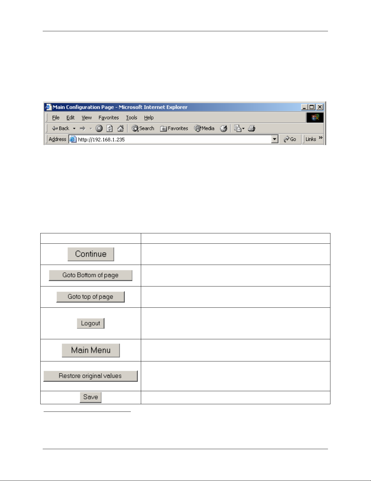
The X501NET configuration interface is a series of web pages that can be accessed through any
web browser. Access to this interface is accomplished by putting the TCP/IP address of the
device to be configured into web browser’s address bar and pressing the enter key.
The above picture shows using Internet Explorer to access an X501NET at address7
192.168.1.235.
2.1 Common Elements
The X501NET configuration uses common elements as much as possible to make the interface
consistent and easy to use.
2.1.1 Common Buttons
Button Action
Pressing the Continue button takes the user to the previous
page.
Pressing the Goto Bottom of page button takes the user
to the bottom of the current page.
Pressing the Goto top of page button takes the user to
the top of the current page.
Pressing the Logout button logs out the current user. After
pressing the Logout button it is necessary for a user to login
before any other menu pages can be accessed.
Pressing the Main Menu button takes the user to the Main
Menu page.
Pressing the Restore original values button restores
the last saved values for all parameters on the page. Note: it
does NOT restore the values to original factory settings.
7
When an X501NET is manufactured it programmed with the default TCP/IP address of 192.168.1.234. Before
it is shipped to the customer it is configured to the specific TCP/IP address required for the customer installation.
Typically, MUX1 has TCP/IP address 192.168.1.234, MUX2 has TCP/IP address 192.168.1.235, and so on.
Pressing the Save button causes the changes made by the
X501NET System Configuration Manual © 2008 Ronan Engineering Company 6
Page 13
Chapter 2 - Interface
Button Action
user on the page to be saved (if the user has sufficient access
rights – see section 2.12.3) and then takes the user to the
appropriate results page (see section 2.1.2).
2.1.2 Results Pages
Whenever a user attempts to perform an action (e.g. Save), they are taken to a results page to
inform the user if the action was successful or if the action failed. In addition, results pages (e.g.
the No Rights page) is reached if a user attempts to go a page that thy are not permitted to
access.
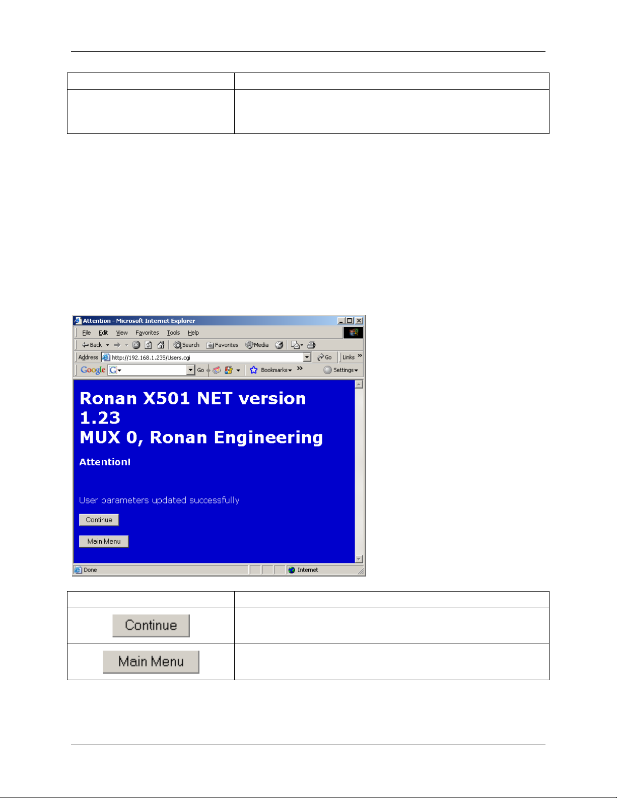
2.1.2.1 Success Page
The Success page is reached when a user performs an action (e.g. Save) that is successfully
completed.
Button Action
Pressing the Continue button takes the user to the previous
X501NET System Configuration Manual © 2008 Ronan Engineering Company 7
page.
Pressing the Main Menu button takes the user to the Main
Menu page.
Page 14
Chapter 2 - Interface
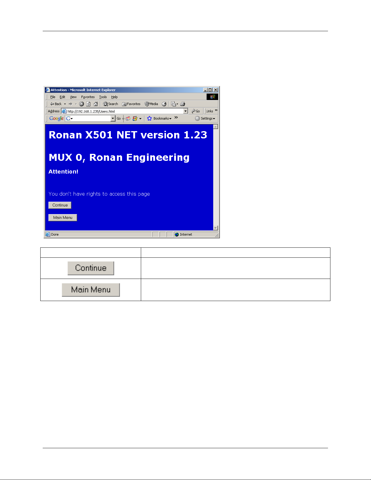
2.1.2.2 No Rights Page
The No Rights page is reached when a user attempts to go to a page or perform an action (e.g.
Save) that is not permitted by the user’s access rights (see section 2.12.3).
Button Action
Pressing the Continue button takes the user to the previous
2.2 Main Menu Page
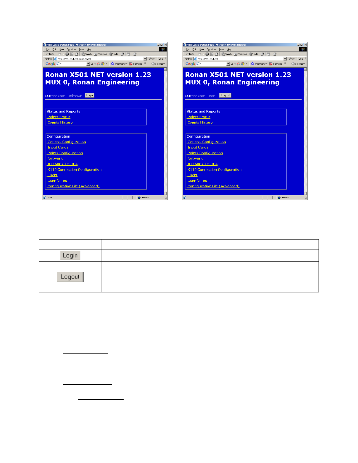
The Main Menu page displays login status and the menu for accessing the status and
configuration pages. In order to access any of those pages the user must login (see section 4.1).
The Login page will be displayed automatically if the user attempts to access any page without
being logged in.
page.
Pressing the Main Menu button takes the user to the Main
Menu page.
X501NET System Configuration Manual © 2008 Ronan Engineering Company 8
Page 15
Chapter 2 - Interface
Main Menu – Not Logged In Main Menu –Logged In
2.2.1 Main Menu Page Buttons
Button Action
2.2.2 Status and Reports
The Status and Report portion of the Main Menu page contains links that are used to view
operational information (current point state and history). These links can be accessed by all users
(Administrators, Operators, and Guests).
2.2.2.1 Points Status Link
Clicking the Point Status
Pressing the Login button takes the user to the Login page.
Pressing the Logout button logs out the current user. After pressing the
Logout button it is necessary for a user to login before any other pages
can be accessed.
link takes the user to the Point Status page (see section 2.4).
2.2.2.2 Events History Link
Clicking the Event History
X501NET System Configuration Manual © 2008 Ronan Engineering Company 9
link takes the user to the Event History page (see section 2.5).
Page 16

Chapter 2 - Interface
2.2.3 Configuration
The Configuration portion of the Main Menu page contains links that are used to view or
change configuration information. These links can only be accessed by users that have
Administrator or Operator access rights.
2.2.3.1 General Configuration
Clicking the General Configuration
page (see section 2.6). This page shows the device’s physical and logical addresses, and time
subsystem parameters. This page also allows these parameters to be changed if the user has
Administrator access rights.
2.2.3.2 Input Cards Link
Clicking the Input Cards Link takes the user to the Input Cards page (see section 2.7). This
page displays the status of all input cards and can be used by an Administrator to enable/disable
and configure input cards.
2.2.3.3 Points Configuration Link
Clicking the Points Configuration Link takes the user to the Points Configuration
page (see section 2.8). The Points Configuration page provides a means to view and/or
configure the parameters of each input point of the X501NET, as well as a means to navigate
through the points.
2.2.3.4 Network Link
Link
Link takes the user to the General Configuration
Clicking the Network Link takes the user to the Network page (see section 2.9). The
Network page provides a means to view and configure the parameters of the TCP/IP protocol
used by the X501NET.
2.2.3.5 IEC 60870-5-104
Clicking the IEC 60870-5-104
section 2.10). The IEC 60870-5-104 page allows the user to view/modify the parameters of
the IEC 60870-104-5 Protocol. This Protocol is used for communication between the X501NET
and IEC60870 master stations.
2.2.3.6 X110 Connection Configuration
Clicking the X110 Connection Configuration
Connection Configuration page (see section 2.11). The X110 Connection
Configuration page is used to setup the Ethernet communication with up to four X110
annunciators.
X501NET System Configuration Manual © 2008 Ronan Engineering Company 10
Link
Link takes the user to the IEC 60870-5-104 page (see
Link
Link takes the user to the X110
Page 17
Chapter 2 - Interface
2.2.3.7 Users Link
Clicking the Users link takes the user to the Users page (see section 2.12). The Users page
can only be accessed by administrators. It enables administrators to permit up to 10 users to
access the X501NET configuration pages and to assign to each user appropriate access rights.
2.2.3.8 User Notes
Link
Clicking the User Notes link takes the user to the User Notes page (see section 2.13). The
User Notes page allows the user to enter plain text notes
8
and to modify/delete the previous
notes.
2.2.3.9 Configuration File Link
Clicking the Configuration File link takes the user to the Configuration File page (see
section 2.14). The Configuration File page can only be accessed by administrators. It
displays the entire content of the X501NET’s configuration file and allows administrators to
change any parameter.
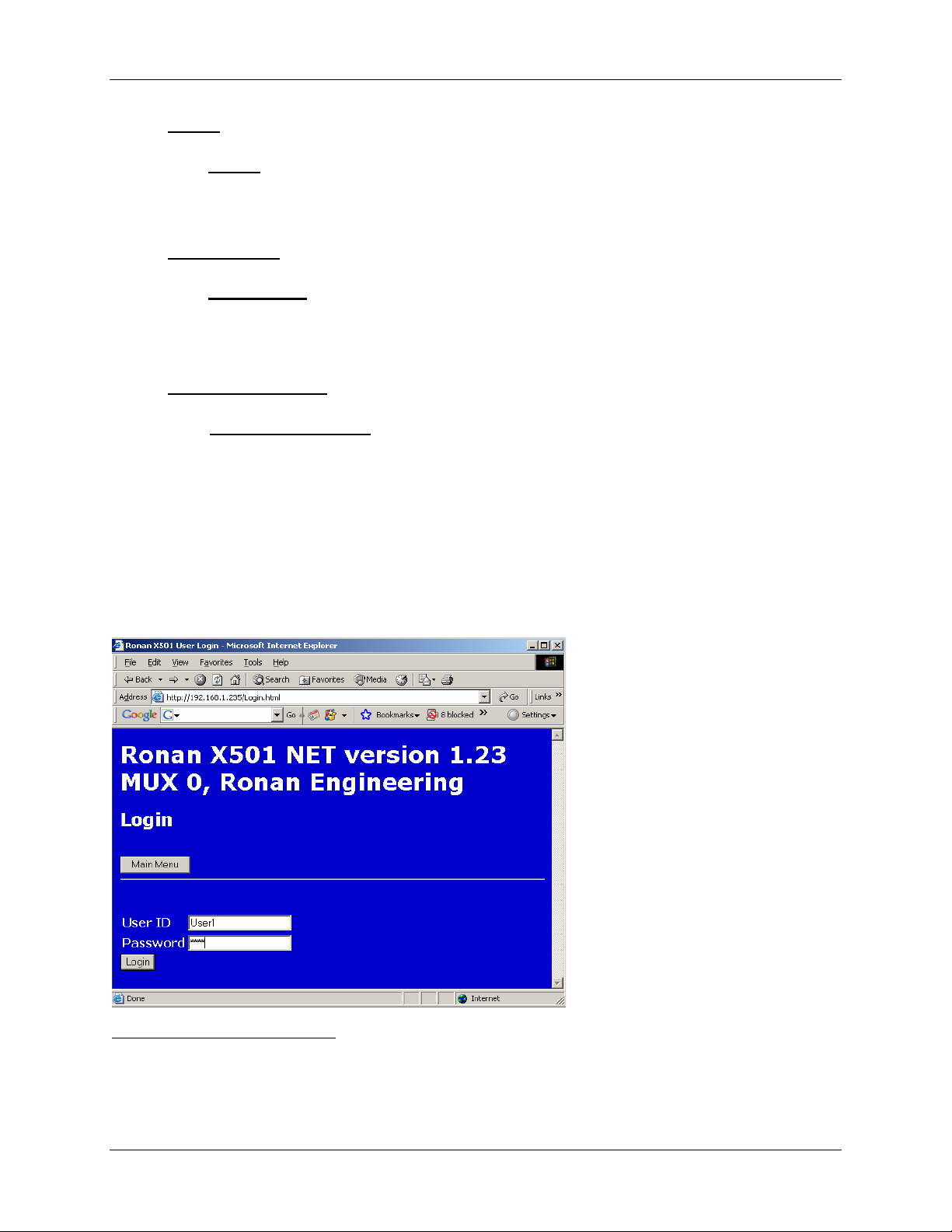
2.3 Login Page
To prevent unauthorized personnel from accessing the X501NET configuration, all users must
login9 before any menu items can be selected.
8
The X501NET can store to 999 bytes of notes.
9
User can log out by clicking the Logout button found on almost every page. Users are also automatically logged
out when they have been inactive for longer than the inactivity timer (about 20 minute if cookies are enabled, only
about 1 minute if they are not).
X501NET System Configuration Manual © 2008 Ronan Engineering Company 11
Page 18
Chapter 2 - Interface
To login in, the user is required to enter User ID (User1 in the example screen shown above),
Password (asterisks automatically replaces characters typed in the password field to help
maintain system security) and press the Login button.
2.3.1 Login Page Buttons
Button Action
Pressing the Login button causes the User ID and
2.3.2 User ID and Password
Both User IDs and Passwords are case sensitive (i.e. A is not the same as a). See Section 4.8
for information on how add users to the system.
Password entered to be checked and, if valid, the
appropriate access level is granted.
Pressing the Main Menu button takes the user to the Main
Menu page.
2.4 Point Status Page
The Point Status page displays the status of every input point in the X501NET. As a result
the page is very long. To assist in page navigation, there are buttons at the top and bottom of the
page to jump from top to bottom.
This page does not allow for direct modifications of the point configuration parameters.
However, each row displays a link to the corresponding Point Configuration page.
X501NET System Configuration Manual © 2008 Ronan Engineering Company 12
Page 19

Chapter 2 - Interface
Top of Point Status Page Botton of Point Status Page
2.4.1 Point Status Page Buttons
Button Action
Pressing the Goto Bottom of page button takes the user
to the bottom of the Point Status page.
Pressing the Goto top of page button takes the user to
the top of the Point Status page.
Pressing the Logout button logs out the current user. After
pressing the Logout button it is necessary for a user to login
before any other menu pages can be accessed.
Pressing the Main Menu button takes the user to the Main
Menu page.
Pressing the Refresh button reloads the page with the
current status of all points.
X501NET System Configuration Manual © 2008 Ronan Engineering Company 13
Page 20

Chapter 2 - Interface
Button Action
Pressing a button with a number in it takes the user to the
thru
2.4.2 Point List
The point list is a table where each line contains information about a point. The information in
the table is current when the page is generated but it is NOT automatically updated while the
page is viewed. Pressing the Refresh button will cause the page to be regenerated to provide a
new snapshot of point status.
2.4.2.1 Point
The Point column of the point list contains a button with the number of the point (0 to 127).
Pressing this button takes the user to the Point Configuration page (see section 2.7.2) for
that number point (if the user has sufficient access rights – see section 2.12.3).
Point Configuration page (see section 2.7.2) for that
number point (if the user has sufficient access rights – see
section 2.12.3).
2.4.2.2 LogAddr
The LogAddr column of the point list contains the Logical Address of the point as defined in
the Point Configuration page for that point.
2.4.2.3 Tag
The Tag column of the point list contains the Tag of the point as defined in the Point
Configuration page for that point.
2.4.2.4 State Legend
The State Legend column of the point list contains the legend (defined in the Point
Configuration page for that point) that corresponds to the current state of the point.
2.4.2.5 Polarity
The Polarity column of the point list contains the Polarity of the point as defined in the Point
Configuration page for that point.
2.5 Event History Page
The Event History page displays a window into the most recent events (up to 8000) that are
present in the X501NET’s event buffer.
X501NET System Configuration Manual © 2008 Ronan Engineering Company 14
Page 21

Chapter 2 - Interface
2.5.1 Event History Page Buttons
Button Action
Pressing the Goto Bottom of page button takes the user
to the bottom of the current page.
Pressing the Goto top of page button takes the user to the
top of the current page.
Pressing the Logout button logs out the current user. After
pressing the Logout button it is necessary for a user to login
before any other menu pages can be accessed.
Pressing the Main Menu button takes the user to the Main
Menu page.
Pressing the << button cause the page to display events
starting with the earliest events in the event buffer.
Pressing the < button cause the page to display the previous
page of events in the event buffer.
X501NET System Configuration Manual © 2008 Ronan Engineering Company 15
Page 22

Chapter 2 - Interface
Button Action
Pressing the > button cause the page to display the next page
2.5.2 History
Each event history line contains the information captured by the multiplexer about a single event.
2.5.2.1 Event ID
The Event ID field is a sequential hexadecimal number assigned to the specific event.
2.5.2.2 mm/dd/yyyy
The mm/dd/yyyy field is the date of the event represented as a two digit day, a slash, a two
digit month, a slash, and a four digit year.
of events in the event buffer.
Pressing the >> button cause the page to display events
starting with the most recent events in the event buffer.
2.5.2.3 hh:mm:ss.ms
The hh:mm:ss.ms field is the time of the event represented as a two digit hour10, a colon, a
two digit minute, a colon a 2 digit second, a period and a 3 digit millisecond.
2.5.2.4 Addr/Msg
The Addr/Msg field contains either a point number or a message identifier.
Message identifiers can be distinguished from point numbers by the prefix M that precedes the
message number (e.g. M274 is the message identifier for Network Line ok). All messages
include a plain text description in Tag/Message field of the condition that caused to message to
be generated.
2.5.2.5 Key
The Key field contains:
Key
AC
AO
MUX
NC
NO
TO
10
Hours are in 24 hour form. 0 is 12 midnight, 12 is 12 noon, 23 is 11 PM.
Meaning
Point is configured as normally open and it is in alarm.
Point is configured as normally closed and it is in alarm.
Event is generated by the X501NET, not by a point.
Point is configured as normally closed and it is not in alarm.
Point is configured as normally open and it is not in alarm.
Point is toggling (an alarm condition) and has entered limit mode.
X501NET System Configuration Manual © 2008 Ronan Engineering Company 16
Page 23

Chapter 2 - Interface
2.5.2.6 Tag/Message
The Tag/Message field contains either a tag name assigned to the point or the Message if the
event is generated by the X501NET (see section 2.5.2.4).
2.5.2.7 Legend/Description
The Legend/Description field contains either a legend associated with the current point state
or the description associated with the event generated by the X501NET (see section 2.5.2.4).
2.6 General Configuration Page
The General Configuration page shows the device’s physical and logical addresses, and
time subsystem parameters. This page also allows these parameters to be changed if the user has
Administrator access rights.
X501NET System Configuration Manual © 2008 Ronan Engineering Company 17
Page 24

Chapter 2 - Interface
2.6.1 General Configuration page Buttons
Button Action
Pressing the Logout button logs out the current user. After
pressing the Logout button it is necessary for a user to login
before any other menu pages can be accessed.
Pressing the Main Menu button takes the user to the Main
Menu page.
Pressing the Restore original values button restores
the last saved values for all parameters on the page. Note: it
does NOT restore the values to original factory settings.
Pressing the Save button causes the changes made by the
user on the page to be saved (if the user has sufficient access
rights – see section 2.12.3) and then takes the user to the
appropriate results page (see section 2.1.2).
Pressing the SetNV Time button sets the time of the builtin real-time clock11 (if the user has sufficient access rights –
see section 2.12.3) and then takes the user to the appropriate
results page (see section 2.1.2). Note: this feature is only for
systems that do not have SNTP, IRIG or GPS time sources
available.
2.6.2 Basic Multiplexer Configuration
These fields set the basic multiplexer configuration. They deal with addressing and identification
of the X501NET and the events generated by the X501NET. The configuration of these fields is
dependent on the type of configuration (non-redundant vs. redundant) and the desired mapping
of logical to physical addresses.
2.6.2.1 Mux ID (Physical Address) Field
Each X501NET must be assigned a unique physical address (typically in the range of 1 through
50).
2.6.2.2 Keep Logical=Physical Check Box
Check the Keep Logical=Physical box if the X501NET is being used in a non-redundant
12
configuration
11
The built-in real-time contains a battery backup that allows it to maintain time accurate within ?? ms even if the
X501NET is not connected to power for ?? days.
12
The X501NET can be use in both non-redundant and redundant configurations. When the X501NET is in a non-
redundant configuration, it typically uses the same logical address as the physical address.
.
X501NET System Configuration Manual © 2008 Ronan Engineering Company 18
Page 25

Chapter 2 - Interface
2.6.2.3 Mux Node Logical Address Field
The Mux Node Logical Address field is used to assign the same logical to both of the
devices that make up the redundant pair.
2.6.2.4 All Points Same Logical Address Check Box
For cases where the X501NET Multiplexer is redundant, and the logical address is the same for
all points, but different than the physical, change the X501NET Multiplexer Node parameter and
check the box All Points Same Logical Address.
For redundant configurations where each point could have any logical addressm the All Points
Same Logical Address must be left unchecked and each of the points must be assigned to the
appropriate logical address using the point configuration screen.
2.6.2.5 Points Display Offset Field
By default all points in the X501 are zero based, i.e. the first point is number 0. There are
applications where the customer may want to see them starting from 1, or even another
number13. The Point Display Offset is used for this purpose. It is important to note that setting
this field to a value different than zero will not affect the communication with other devices
(except the X11014) and is used only to offset the display of the point on the X501NET
Multiplexer local pages (e.g. the Points Status and Point Configuration pages).
2.6.2.6 Mux Tag Field
The X501NET Mux Tag parameter is displayed on each page by this configuration interface.
2.6.3 Time Configuration
Time stamping events with the accurate time of occurrence is one of the main tasks of the
X501NET. Since this is such an important function, the X501NET supports many options to
assure that it can have as accurate a time stamp as possible15.
2.6.3.1 NTP Servers Field
The X501NET is able to receive the time using SNTP protocol. The time received from the NTP
servers can be:
• the primary time source for the X501NET, or
• a fall-back time source that is used in case any better quality16 time source is not
available.
13
Valid values for this field are 0 through 65525.
14
This parameter is also used to offset the points for X110 communication.
15
Within the limits of the time sources provided.
16
The NTP precision is about ±10 ms in most of the local networks.
X501NET System Configuration Manual © 2008 Ronan Engineering Company 19
Page 26

Chapter 2 - Interface
If the SNTP protocol is to be used to obtain time, the NTP Servers field must contain a list of
the TCP/IP addresses NTP servers. Up to four TCP/IP server addresses can be listed, separated
by semicolons.
2.6.3.2 Time Zone Field
The Time Zone field is used to add a signed offset to the time obtained through GPS or SNTP.
In the case of using IRIG-B for synchronization, the time is directly set without taking into
account the time zone.
2.6.3.3 NTP Acquisition Interval Fields
This field, NTP Acquisition Interval, and the following field, NTP Switch Timeout, are
used to control the frequency of polling the time server and the timeout after which to switch to
NTP in the case of the loss of a better quality time17 source18 (i.e. GPS or IRIG-B).
The NTP Acquisition Interval field is used to control how often (in seconds) an NTP server is
polled when that server is being used as the time source.
2.6.3.4 NTP Switch Timeout Field
The NTP Switch Timeout field is used to determine how long (in seconds) the X501NET will
wait after losing a higher quality time server before it starts to get time form an NTP server (also
see section 2.6.3.3).
2.6.3.5 Preferred Time Source Field
The Preferred Time Source field displays, and allows an Administer to change, the primary
time source to be used by the X501NET.
Preferred
Time
Source Description
None
No external time source is available, see the description of the SetNV
Time button in section 2.6.1 for information on setting the internal
real-time clock.
GPS
IRIG-B
SNTP
Use an external GPS receiver as the primary time source.
Use an external IRIG-B time code generator as the primary time source.
Use a network time server as the primary time source.
17
Higher accuracy or more reliable.
18
In many cases the X501NET MULTIPLEXER could temporarily lose the satellite connection (GPS) or the IRIGB synchronization and since the timing subsystem will continue to run on the last known good settings it is
undesirable to switch immediately to NTP. The default value is 60 seconds, but values up to one hour (3600 s) could
be acceptable.
X501NET System Configuration Manual © 2008 Ronan Engineering Company 20
Page 27

Chapter 2 - Interface
Note, if an IRIG-B is connected as a time source, do not select None. This can cause the year to
be unreliable.
2.6.3.6 IRIG-B mode Field
If an IRIG-B time code generator is connected to the X501NET, this field must be set to select to
mode19 of operation of the IRIG-B20 interface.
IRIG-B mode Description
Standard
Ronan enhanced
Use with standard (non-Ronan) IRIG-B time generators
Use Ronan enhanced time code generators that provide year in addition
the standard IRIG-B information.
Auto-sensing
Automatically21 select the correct IRIG-B mode.
Setting this field is very important. If a Ronan enhanced IRIG-B is not attached (either a
standard IRIG-B or no IRIG-B) the field must be set to Standard to avoid a risk of having the
year change due to noise on the IRIG-B port.
2.7 Input Cards Page
The Input Cards page displays the status of all input cards, and can be used by an
Administrator to enable/disable and configure input cards.
19
Since the standard IRIG-B frame doesn’t carry information about the year, Ronan Engineering has developed a
proprietary extension of the IRIG-B protocol that passed the year as additional frame validation information.
20
Specifically IRIG-B120.
21
Since the automatic selection of IRIG-B mode can not be guaranteed compatible with all non-Ronan time code
generators, this mode should not be used unless it is not possible to determine what type of IRIG-B generator is
connected to the X501NET.
X501NET System Configuration Manual © 2008 Ronan Engineering Company 21
Page 28

Chapter 2 - Interface
2.7.1 Input Cards Page Buttons
Button Action
Pressing the Goto Bottom of page button takes the user
to the bottom of the current page.
Pressing the Goto top of page button takes the user to
X501NET System Configuration Manual © 2008 Ronan Engineering Company 22
the top of the current page.
Pressing the Logout button logs out the current user. After
pressing the Logout button it is necessary for a user to login
before any other menu pages can be accessed.
Page 29

Chapter 2 - Interface
Button Action
Pressing the Main Menu button takes the user to the Main
2.7.2 Card Configuration
The X501NET configuration displays input card type and status and input cards operation to be
controlled.
2.7.2.1 Global Test Interval Field
Menu page.
Pressing the Refresh button reloads the page with the
current status of all cards.
Pressing the Save button causes the changes made by the
user on the page to be saved (if the user has sufficient access
rights – see section 2.12.3) and then takes the user to the
appropriate results page (see section 2.1.2).
In most cases it is preferred to use the same test interval for all cards. If the Global Test
Interval to a number different than 0 all input cards (capable of running an input test) are tested
at that interval22.
2.7.2.2 Card Field
The Card field is read-only. It identifies the card slot (1 through 16) associated with the row of
fields.
2.7.2.3 Enabled Field
If the card is present but not required to report data, it can be disabled by clearing the check in
the Enabled column.
2.7.2.4 Model Field
The Model field is read-only. It contains the model name (e.g. X501-312) of the card in the slot
(1 through 16) associated with the row.
2.7.2.5 Status Field
The Status field is read-only. It contains the status of the card in the slot (1 through 16)
associated with the row:
Status Enabled Card in Slot
Normal
Not Configured and Present
checked yes
not checked yes
22
Individual Interval settings are ignored.
X501NET System Configuration Manual © 2008 Ronan Engineering Company 23
Page 30

Chapter 2 - Interface
Status Enabled Card in Slot
Configured and missing
Not Available
checked no
not checked no
2.7.2.6 Test Field
The Test field allows input card test to be enabled23 (field checked) or disabled (field not
checked) on an individual card basis.
2.7.2.7 Interval Field
The Interval field allows interval between tests card test to be assigned24 on an individual card
basis.
Regardless that it is possible to assign an individual loop test interval for each card, in most cases
it is preferred to use single and same for all cards intervals. By setting Global Loop Test interval
to a number different than 0 the individual intervals are disregarded
2.8 Points Configuration Page
The Points Configuration page provides a means to view and/or configure the
parameters of each input point of the X501NET, as well as a means to navigate through the
points.
23
Not all input cards (e.g. X501-307N) have hardware capabilities for performing this test. If a is enabled and the
card can not perform the test, the test will not be run on the card.
24
Although that it is possible to assign an individual loop test interval for each card, in most cases it is preferred to
use single and same for all cards intervals. If the Global Test Interval to a value different than 0 the individual
Intervals are disregarded.
X501NET System Configuration Manual © 2008 Ronan Engineering Company 24
Page 31

Chapter 2 - Interface
2.8.1 Points Configuration Page Buttons
Button Action
Pressing the First button cause the page to display the first
point.
Pressing the Last button cause the page to display the last
point.
Pressing the Logout button logs out the current user. After
pressing the Logout button it is necessary for a user to login
before any other menu pages can be accessed.
Pressing the Main Menu button takes the user to the Main
Menu page.
Pressing the Next button cause the page to display the first
point.
X501NET System Configuration Manual © 2008 Ronan Engineering Company 25
Page 32

Chapter 2 - Interface
Button Action
2.8.2 Point Parameters
Pressing the Point List button takes the user to the Point
Status page.
Pressing the Prev button cause the page to display the
previous point.
Pressing the Refresh button reloads the page with the
current status of all cards.
Pressing the Restore original values button restores
the last saved values for all parameters on the page. Note: it
does NOT restore the values to original factory settings.
Pressing the Save button causes the changes made by the
user on the page to be saved (if the user has sufficient access
rights – see section 2.12.3) and then takes the user to the
appropriate results page (see section 2.1.2).
All point parameters are displayed on this page.
2.8.2.1 Physical Address Field
The Physical Address field is read-only on this page. This parameter can be changed on the
General Configuration page or by modifying the configuration file.
2.8.2.2 Current State Field
The Current State field is read-only and represents the point’s status at the time the Point
Points Configuration page was displayed25.
2.8.2.3 Logical Address Field
The Logical Address field contains the logical address for the point (see sections 2.6.2.3,
2.6.2.4 and 2.6.2.5 for information on how the logical address is composed).
2.8.2.4 Tag Field
The Tag field contains the name26 of the point.
25
Note that the state does not stay current and the Refresh button needs to be pressed to re-
display the page to see what, if any, change has occurred to point status.
26
User defined name of point.
X501NET System Configuration Manual © 2008 Ronan Engineering Company 26
Page 33

Chapter 2 - Interface
2.8.2.5 Alarm Legend Field
The Alarm Legend Field contains the text to be displayed when the point is in the alarm state.
This legend is displayed as the State Legend on the Points Status page and Current
State on the Point Setup page when the point is in the alarm state.
2.8.2.6 Normal Legend Field
The Normal Legend Field contains the text to be displayed when the point is in the normal
state. This legend is displayed as the State Legend on the Points Status page and
Current State on the Point Setup page when the point is in the normal state.
2.8.2.7 Toggle Legend Field
The Toggle Legend Field contains the text to be displayed when the point is toggling (see
section 2.8.2.14 for a explanation of the criteria for a point to toggling). This legend is displayed
as the State Legend on the Points Status page and Current State on the Point Setup
page when the point is toggling.
2.8.2.8 Polarity Field
The Polarity field is a pull-down menu. The choices in the menu for this field are Normally
open or Normally closed. The value selected represents the state the point is normal27.
2.8.2.9 In Service Field
The In Service field is a pull-down menu. The choices in the menu for this field are Yes or No.
Yes enables the point, No disables the point.
2.8.2.10 Filter Type Field
The Filter Type field is a pull-down menu. The choices in the menu for this field are 1, 2, 3, 4,
5, 6, 7, 8, 9, or 10. Each number represents a type of filter. The filter types 1 through 5 are
consecutive filters. The filter types 6 through 10 are integrating filters.
2.8.2.10.1 Consecutive Filter
The consecutive type filter employs a counter for the input, which is activated when the
monitoring system samples the point contact. The contact is scanned every millisecond (1/1000
of a second). The counter begins to tally when a change in the point contact is first detected. If
the specified number of consecutive scans reflect this change, an event is recorded. Should the
point sample return to the original state before the specified number of consecutive scans
elapses, the count returns to zero. The Alarm Time Constant (see section 2.8.2.11) specifies
the count required to enter the alarm condition and the Normal Time Constant (see section
2.8.2.12) specifies the count required to return to normal.
27
When the point is in the opposite state it is in alarm.
X501NET System Configuration Manual © 2008 Ronan Engineering Company 27
Page 34

Chapter 2 - Interface
2.8.2.10.2 Integrating Filter
The integrating type filter method is similar to the consecutive filtering approach, except an
up/down counter is used to track the status of the point contact. The process begins in the same
manner as the consecutive filter. The counter begins to tally when a change in the point’s input
contact is first detected. During each scan in which the new contact status is maintained, the
count is incremented by one. The event is recorded when the specified count is reached. (Each
count equals one millisecond.) The difference is that an input sample that shows a return to the
original state merely causes one to be subtracted from the count, rather than resetting the counter
to zero. If the next scan reflects a change, the counter is again increased. Should the count be
reduced to zero after the initial state has been maintained for a specified number of counts, the
counter will remain at zero until a new change has been detected. The Alarm Time Constant
(see section 2.8.2.11) specifies the count required to enter the alarm condition and the Normal
Time Constant (see section 2.8.2.12) specifies the count required to return to normal.
2.8.2.10.3 Filter Time Constants
In addition to determining the type of filter (integrating or consecutive), th e selected filter type
also determines the group of constants available for:
• alarm time,
• return to normal, and
• de-bounce time.
The following table shows which group of time constants is associated with each filter type for
each of the three time parameters of the filter.
Filter Type
Selected
Type of
Filter
Alarm Time
Constant Group
Return to Normal
Constant Group
De-Bounce28 Time
Constant Group
1 Integrating Low Low 0 or Low
2 Integrating Low Medium 0
3 Integrating Medium Medium Low
4 Integrating Medium Equal to Alarm 0
5 Integrating High Equal to Alarm 0
6 Consecutive Low Low 0 or Low
7 Consecutive Low Medium 0
8 Consecutive Medium Medium Low
9 Consecutive Medium Equal to Alarm 0
10 Consecutive High Equal to Alarm 0
28
For both the integrating or consecutive type of filter, the debounce time allows the user to specify a time period
which must elapse before either the consecutive state or integrating filter methods are activated.
X501NET System Configuration Manual © 2008 Ronan Engineering Company 28
Page 35

Chapter 2 - Interface
If an entry in the table specifies “0” or “Equal to Alarm”, then there is no choice of this filter
parameter. The parameter is automatically set to 0 or the same value as selected for the alarm
time constant, respectively.
2.8.2.10.3.1 Low Time Constants Group
The low time constant group allows a choice of times between 1 ms and 255 ms in 1 ms steps.
When a time constant is specified in the table above as “0 or Low”, the range of choices allowed
is 0 ms to 255 ms in 1 ms steps.
2.8.2.10.3.2 Medium Time Constants Group
The medium time group allows the following choices:
Selected Value Time in Milliseconds Approx. Time in Seconds
256 ms 256 256
512 ms 512 512
1K ms 1024 1.024
2K ms 2048 2.048
4K ms 4096 4.096
8K ms 8192 8.192
16K ms 16384 16.384
32K ms 32768 32.768
2.8.2.10.3.3 High Time Constants Group
The high time group allows the following choices:
Selected Value Time in Milliseconds Approx. Time in Minutes
64K ms (1.09 min) 65,536 1.09
128K ms (2.18 min) 131,072 2.18
256K ms (4.37 min) 262,144 4.37
512K ms (8.74 min) 524,288 8.74
1M ms (17.48 min) 1,048,576 17.48
2M ms (34.95 min) 2,097,152 34.95
4M ms (69.90 min) 4,194,304 69.90
8M ms (139.81 min) 8,388,608 139.81
X501NET System Configuration Manual © 2008 Ronan Engineering Company 29
Page 36

Chapter 2 - Interface
2.8.2.11 Alarm Time Constant Field
The Alarm Time Constant Field is a pull down menu. The possible values of this parameter
change depending on the on the filter type selected (see 2.8.2.10).
2.8.2.12 Normal Time Constant Field
The Normal Time Constant Field is a pull down menu. The possible values of this parameter
change depending on the on the filter type selected (see 2.8.2.10).
2.8.2.13 Debounce Time Constant Field
The Debounce Time Constant Field is a pull down menu. The possible values of this
parameter change depending on the on the filter type selected (see 2.8.2.10). The time constant
set by this field is used to filter noise and is applied to the data before the data is filtered.
2.8.2.14 Toggling Interval [ms] Field
The toggling (also called limit) mode is a mode that introduces another state for a point –
toggling. For points that change their state (alarm or normal) too often, either because of sensor
malfunction or the nature of the signal itself, like level switches in a tank with waves, it is
sometimes preferred to report this state only once instead of overfilling the events history with
multiple transitions.
The parameter that controls the toggling mode is the interval during which a number of state
transitions have occurred. The interval is entered in milliseconds and could be up 65536
milliseconds (65 seconds). The number of state changes (trips) is limited to 16.
Once the point enters a toggling mode it will be reported only once and the point will stay in this
state as long as the condition exists, i.e. the number of state trips for the last Toggling Interval
milliseconds is equal or greater than the programmed value. If the condition disappears the point
will be reported to its real state. Of course, if the point still changes state but with lower
frequency all changes will be reported.
2.8.2.15 Toggling Trips Field
See section 2.8.2.14.
2.9 Network Page
The Network page provides a means to view and configure the parameters of the TCP/IP
protocol used by the X501NET.
X501NET System Configuration Manual © 2008 Ronan Engineering Company 30
Page 37

Chapter 2 - Interface
By default the factory29 settings are:
• Static configuration
• IP address: 192.168.1.234
• IP Network Mask: 255.255.255.0
• Default gateway: 192.168.1.1
• Name Server: 192.168.1.1
Note: changes to the IP configuration do not take effect until the X501NET is rebooted.
2.9.1 Network page Buttons
Button Action
Pressing the Logout button logs out the current user. After
29
Before January 14, 2008, the factory settings were DHCP and on fail to use the static address. The X501NETs
with these setting are at risk of losing communication with the Ronan Master Station (e.g. AlarmX) if:
• that setting is not changed,
• a DHCP server is added to the local area network with the X501NET, and
• the X501NET is restarted (e.g. power fail).
pressing the Logout button it is necessary for a user to login
before any other menu pages can be accessed.
X501NET System Configuration Manual © 2008 Ronan Engineering Company 31
Page 38

Chapter 2 - Interface
Button Action
Pressing the Main Menu button takes the user to the Main
2.9.2 DHCP
Although the X501NET supports the use of a DHCP server30, all of the current Ronan SERs
expect to find the X501NET via a static IP address. Never check the box Configure through
DHCP unless you are sure that all portions of the SER system that must communicate with the
X501NET are compatible with this feature.
Menu page.
Pressing the Restore original values button restores
the last saved values for all parameters on the page. Note: it
does NOT restore the values to original factory settings.
Pressing the Save button causes the changes made by the
user on the page to be saved (if the user has sufficient access
rights – see section 2.12.3) and then takes the user to the
appropriate results page (see section 2.1.2). However, changes
made do not take effect until the X501NET is rebooted.
2.9.3 Static Address
The X501NET is typically connected to a network that only has devices associated with the SER
system. In this case a DHCP server is typically not present on the network. It the X501NET is
attached to a network that had non-Ronan devices attached, you MUST coordinate with the
network administrator to assure that the static addresses assigned to the X501NET are also
controlled by the network’s DHCP server.
2.9.3.1 IP Address Field
When an X501NET is manufactured it is programmed with the default TCP/IP address of
192.168.1.234. Before it is shipped to the customer it is configured to the specific TCP/IP
address required for the customer installation. Typically, MUX1 has TCP/IP address
192.168.1.234, MUX2 has TCP/IP address 192.168.1.235, and so on.
2.9.3.2 IP Network Mask Field
If the X501NET is connected to a network that only has devices associated with the SER system,
the IP Network Mask is typically 255.255.255.0. If the X501NET is attached to a
30
The X501NET can be configured to obtain its IP address and the other TCP/IP parameters dynamically through
the DHCP protocol or to use static values. Since revision 1.8 it is possible to select DHCP configuration and, if the
DHCP fails or times out, to set X501NET to the static settings. This is very convenient when configuring the device
at the office where DHCP is normally present and without reconfiguring it back to be used later at an installation
where fixed IP addresses are used.
X501NET System Configuration Manual © 2008 Ronan Engineering Company 32
Page 39

Chapter 2 - Interface
network that has non-Ronan devices attached, the IP Network Mask must be the same as the
mask used on the other network devices.
2.9.3.3 Default Gateway Field
If the X501NET is connected to a network that only has devices associated with the SER system,
the Default Gateway is typically 192.168.1.1. It the X501NET is attached to a network
that has non-Ronan devices attached, the Default Gateway should be the same as the network
gateway used by the other network devices.
2.9.3.4 Name Server Field
If the X501NET is connected to a network that only has devices associated with the SER system,
the Name Server is typically 192.168.1.1. It the X501NET is attached to a network that
has non-Ronan devices attached, the Name Server should be the same as the name server used
by the other network devices.
2.10 IEC 60870-5-104 Page
The IEC 60870-5-104 page allows the user to view and modify the parameters of the IEC
60870-104-5 Protocol31.
31
This Protocol is used for communication between the X501NET and master stations such as the IEC60870
Producer that is part of the AlarmX software product.
X501NET System Configuration Manual © 2008 Ronan Engineering Company 33
Page 40

Chapter 2 - Interface
Note: changes to the IEC60870 configuration do not take effect until the X501NET is rebooted.
2.10.1 IEC 60870-5-104 page Buttons
Button Action
Pressing the Logout button logs out the current user. After
X501NET System Configuration Manual © 2008 Ronan Engineering Company 34
pressing the Logout button it is necessary for a user to login
before any other menu pages can be accessed.
Pressing the Main Menu button takes the user to the Main
Menu page.
Pressing the Restore original values button restores
Page 41

Chapter 2 - Interface
Button Action
the last saved values for all parameters on the page. Note: it
does NOT restore the values to original factory settings.
Pressing the Save button causes the changes made by the
user on the page to be saved (if the user has sufficient access
2.10.2 Parameters
These parameters are typically set by Ronan. DO NOT CHANGE ANY OF THESE
PARAMETERS UNLESS YOU COMPLETELY UNDERSTAND IEC 60870 AND HOW
CHANGES CAN AFFECT THE ENTIRE SER SYSTEM.
Changes to these parameters do not take effect until the X501NET is rebooted.
The configuration parameters are:
rights – see section 2.12.3) and then takes the user to the
appropriate results page (see section 2.1.2). However,
changes made do not take effect until the X501NET is
rebooted.
2.10.2.1 Protocol/Disabled Field
The Protocol/Disabled field is a pull-down menu. It should not be changed from its default
value of Profile A.
2.10.2.2 Device ID Field
The Device ID field is a read-only field on this page32. This is an integer number by which the
X501NET MULTIPLEXER is identified within the system.
2.10.2.3 Device Name Field
The Device Name field contains the name of the X501NET that is used for display purposes.
2.10.2.4 Device Password Field
The Device Password field contains the password used by the X501NET to login to the
IEC60870 master station33.
2.10.2.5 IEC60870 Servers Field
The IEC60870 Servers field can be used to limit the IEC60870 communications between the
X501NET and IEC60870 master station to an IEC60870 master station fixed IP address (or set
of IEC60870 master stations at fixed IP addresses).
32
This field can be changed on the General Configuration page.
33
Also known as the IEC 60870 Producer.
X501NET System Configuration Manual © 2008 Ronan Engineering Company 35
Page 42

Chapter 2 - Interface
2.10.2.6 TCP Port Field
The TCP Port field contains the TCP port number used by the X501NET to listen for incoming
connections from the IEC60870 master station.
2.10.2.7 Initial Discovery Port Field
The Initial Discovery Port field contains the UDP port number on which the X501NET
broadcasts the Initial Discovery Datagram34 when no connection exists between it and an
IEC60870 master station. This datagram is broadcast repeatedly until a connection is established.
The datagram contains enough information for an eventual IEC60870 master station to connect
to the X501NET via the IEC60870 protocol.
2.10.2.8 Common ASDU Address Field
The value of this parameter is used for the ASDU Address field of the IEC 60870-5-104 protocol
frames sent from the X501NET to the IEC60870 master station.
2.10.2.9 Originator Address Field
The value of this parameter is used for the Originator Address field of the IEC 60870-5-104
protocol frames sent from the X501NET to the IEC60870 master station.
2.10.2.10 Confirmation Timeout Field
This parameter is the maximum delay in milliseconds for the X501NET to send an activation
confirmation (ACTCON) following an activation request (ACT).
2.10.2.11 Termination Timeout Field
This parameter is the maximum delay in milliseconds for the X501NET to send an activation
termination (ACTTERM) following an activation request (ACT).
2.10.2.12 Window Size (K) Field
Size in KB of the TCP transmit window.
2.10.2.13 Window Size (W) Field
Max number of TCP frames which can be received without the transmission of an ACK frame.
34
This datagram has to be broadcasted because the X501NET doesn’t know in advance the IP address of its
IEC60870 master station.
X501NET System Configuration Manual © 2008 Ronan Engineering Company 36
Page 43

Chapter 2 - Interface
2.10.2.14 Timeout T0 Field
The Timeout T0 field is the controls the T0 delay as defined in the IEC 60870-5-104 standard.
The T0 delay is the timeout interval in seconds for connection establishment.
2.10.2.15 Timeout T1 Field
The Timeout T1 field is the controls the T1 delay as defined in the IEC 60870-5-104 standard.
The T1 delay is the timeout interval in seconds for function confirmations.
2.10.2.16 Timeout T2 Field
The Timeout T2 field is the controls the T2 delay as defined in the IEC 60870-5-104 standard.
The T2 delay is the timeout interval in seconds for ACK receptions.
2.10.2.17 Timeout T3 Field
The Timeout T3 field is the controls the T3 delay as defined in the IEC 60870-5-104 standard.
The T3 delay is the maximum inactivity timeout interval in seconds.
2.10.2.18 Status Point Address Field
The Status Point Address field displays the virtual point address of the X501NET’s status
word and allows this point address to be changed by administrators.
2.10.2.19 Transmit Queue Size Field
This parameter specifies the size of the event buffer.
2.10.2.20 Sync on TimeSync Command Field
This parameter specifies whether to accept the time sync command from and IEC60870 server,
since this synchronization is not precise.
2.11 X110 Connection Configuration Page
The X110 Connection Configuration page is used to setup the Ethernet communication
with up to four X110 Annunciators via TCP or an unlimited number of X110 Annunciators
attached to the same LAN of a UDP broadcast connection.
X501NET System Configuration Manual © 2008 Ronan Engineering Company 37
Page 44

Chapter 2 - Interface
2.11.1 X110 Connection Configuration Page Buttons
Button Action
Pressing the Logout button logs out the current user. After
X501NET System Configuration Manual © 2008 Ronan Engineering Company 38
pressing the Logout button it is necessary for a user to login
before any other menu pages can be accessed.
Page 45

Chapter 2 - Interface
Button Action
2.11.2 Connections
Up to 4 nodes can be configured.
2.11.2.1 Node Field
Pressing the Main Menu button takes the user to the Main
Menu page.
Pressing the Restore original values button restores
the last saved values for all parameters on the page. Note: it
does NOT restore the values to original factory settings.
Pressing the Save button causes the changes made by the
user on the page to be saved (if the user has sufficient access
rights – see section 2.12.3) and then takes the user to the
appropriate results page (see section 2.1.2).
The Node field is read-only. It identifies the the row of fields.
2.11.2.2 Protocol Field
Select the Protocol to use for a node:
• Select Disabled if this node is not in use.
• Select TCP to be able to communicate over both LANs and WANs.
• Select UDP if the communication is only over the same LAN as the X501NET and if
broadcast communication if desired (a broadcast address to be used that to communicate
with an unlimited number of X110s attached to the same LAN).
2.11.2.3 IP Address Field
The IP Address field is to the:
• IP Address of the X110 when TCP is selected as the Protocol
• The broadcast address 255.255.255.255 when UDP is selected.
2.11.2.4 Port Field
The default value for the Port field is 4001. Do not change this value.
2.12 Users Page
The Users page allows administrators to allow up to 10 users to access the X501NET
configuration pages and to assign appropriate access rights to each user.
X501NET System Configuration Manual © 2008 Ronan Engineering Company 39
Page 46

Chapter 2 - Interface
2.12.1 Users Page Buttons
Button Action
Pressing the Goto Bottom of page button takes the user
to the bottom of the current page.
Pressing the Goto top of page button takes the user to
the top of the current page.
Pressing the Logout button logs out the current user. After
pressing the Logout button it is necessary for a user to login
before any other menu pages can be accessed.
Pressing the Main Menu button takes the user to the Main
Menu page.
Pressing the Refresh button reloads the page with the
current status of all users.
X501NET System Configuration Manual © 2008 Ronan Engineering Company 40
Page 47

Chapter 2 - Interface
Button Action
Pressing the Restore original values button restores
the last saved values for all parameters on the page. Note: it
does NOT restore the values to original factory settings.
Pressing the Save button causes the changes made by the
user on the page to be saved (if the user has sufficient access
2.12.2 User Names and Passwords
For each user a Full Name must be entered, as well a Login name and Password.
Warning: If a Full name is not entered the account is automatically disabled.
2.12.3 User Rights
There are currently defined 3 groups: Administrator, Operator and Guest.
rights – see section 2.12.3) and then takes the user to the
appropriate results page (see section 2.1.2).
2.12.3.1 Administrator
A user that has Administrator rights has full access to all menus and the ability to change all
parameters. Administrators can also see and modify the other users’ settings. It is recommended
to keep the number of users with administrator rights as low as possible, preferably one.
2.12.3.2 Operator
A user that has Operator access rights has permission to:
• view all menu pages except the User and the Configuration File pages and
• make changes to the User Notes page.
A user that has Operator access rights can not make any changes to parameters.
2.12.3.3 Guest
A user that has Guest access rights only has permission to:
• view the Point Status page and
• view the Event History page.
A user that has Guest access rights can not modify any settings in the X501NET multiplexer.
2.13 User Notes Page
The User Notes page allows a user to enter plain text notes (up to a limit of 999 characters)
and to modify or delete the previous notes. The notes are kept in the X501NET non-volatile
memory.
X501NET System Configuration Manual © 2008 Ronan Engineering Company 41
Page 48

Chapter 2 - Interface
2.13.1 User Notes Page Buttons
Button Action
Pressing the Logout button logs out the current user. After
pressing the Logout button it is necessary for a user to login
before any other menu pages can be accessed.
Pressing the Main Menu button takes the user to the Main
Menu page.
Pressing the Restore original values button restores
the last saved values for all parameters on the page. Note: it
does NOT restore the values to original factory settings.
Pressing the Save button causes the changes made by the
user on the page to be saved (if the user has sufficient access
rights – see section 2.12.3) and then takes the user to the
appropriate results page (see section 2.1.2).
X501NET System Configuration Manual © 2008 Ronan Engineering Company 42
Page 49

Chapter 2 - Interface
2.14 Configuration File Page
The Configuration File page can only be accessed by administrators. It displays the entire
35
content of the X501NET’s configuration file
and allows an administrator to change any
parameter.
35
The Configuration Agent in the master station (typically AlarmX or some other version of X1000 software)
usually loads this file into the X501NET through a subset of FTP. However, this page provides an alternative way
to view/modify the entire file. Please note that if the file is modified using this page, the file in the master station and
the file in the X501NET may be different.
X501NET System Configuration Manual © 2008 Ronan Engineering Company 43
Page 50

Chapter 2 - Interface
2.14.1 Configuration File Page Buttons
Button Action
Pressing the Logout button logs out the current user. After
pressing the Logout button it is necessary for a user to login
before any other menu pages can be accessed.
Pressing the Main Menu button takes the user to the Main
Menu page.
Pressing the Reset Device button cause the X501NET to
do a hardware reset (if the user has sufficient access rights –
see section 2.12.3) or takes the user to the appropriate results
page (see section 2.1.2) if the user does not have sufficient
access rights.
Pressing the Restore original values button restores
the last saved values for all parameters on the page. Note: it
does NOT restore the values to original factory settings.
Pressing the Save button causes the changes made by the
2.14.2 Configuration File Content
Anytime the X501NET configuration file (see appendix A for and example) is be modified
through the web interface, the X501NET will update its configuration parameters accordingly
and will generate appropriate events. These events will then be sent to the Event Server.
Depending on the parameter type, the new values may take effect immediately or may require
the X501NET to be rebooted before they take effect.
user on the page to be saved (if the user has sufficient access
rights – see section 2.12.3) and then takes the user to the
appropriate results page (see section 2.1.2).
X501NET System Configuration Manual © 2008 Ronan Engineering Company 44
Page 51

Chapter 3 –Initial Configuration
CHAPTER 3 – INITIAL CONFIGURATION
3.1 First Login
When an X501NET is manufactured, it is programmed with the default TCP/IP address of
192.168.1.23436. Before it is shipped to the customer it is configured to the specific TCP/IP
address required for the customer installation. Typically, MUX1 has TCP/IP address
192.168.1.234, MUX2 has TCP/IP address 192.168.1.235, and so on.
Put the address37 of the X501NET that you wish to configure into the address bar of the browser and
press the Enter key. Next, click the Login button on the X501NET Main Menu page. This will take
you to the Login page. Enter your user name and password
Login button on this page. If the user name and password are correct, you will be taken back to the
Main Menu page and be logged in.
3.2 Network Configuration
38
on the Login page and click the
Setting the network address should be the first step in configuring an X501NET. Click on the
Network
link on the Main Menu page to get to the network configuration menu. Check the box
marked Static Configuration39. Fill in the desired network address information (IP address, etc.)
and click SAVE.
Restart the X501NET40. Put the address that you just configured into the address bar of the browser
and press the Enter key. You should see the X501NET Main Menu page again and be able to login.
3.3 User Configuration
The next step is to configure the users of the X501NET. This is very important for security if the
network where the X501NET is not physically secure or where the SER used any public network as
part of its network connection.
Most users do not require Administrator access rights. You should give these rights to as few people as
possible. Keep a copy of a user name/password combination in a safe location. If the administrator
36
This is the same address that is usually used for MUX1. To add a new X501NET to an existing SER, it is necessary to
configure the TCP/IP address before attaching the X501NET to the LAN that is part of the SER. This can be accomplish by
having a user workstation or laptop computer attached to a hub that is not part of the SER LAN and connection the
X501NET to this mini-LAN for configuration before attaching it to the LAN that is part of the SER.
37
See section 4.1 if needed for more information about logging in.
38
The default user name is User1 and the default password is pwd1.
39
Do not select Configure through DHCP and Use the Static IP if the DHCP fails even it there is no DHCP server
on the LAN with the X501NET. Configuring an X501NET in this way can cause the SER to fail if a DHCP server is ever
added to the LAN.
40
The change to the TCP/IP address does not take effect until the X501NET is restarted.
X501NET System Configuration Manual – © 2008 Ronan Engineering Company 45
Page 52

Chapter 3 –Initial Configuration
password(s) is lost, the X501NET controller boards must be returned to Ronan to be reprogrammed to factory defaults.
3.4 General Configuration
The data on the General Configuration page is totally system dependent. Refer to your system
documentation to configure to values on this page.
3.5 Card and Point Configuration
The card and point configuration is typically downloaded to the X501NET by the master station.
3.6 IEC 60870 Configuration
Most systems do not require and IEC 60870 configuration. The only exceptions are systems that use a
public network as part of their network configuration. These systems should configure the IEC 60870
Servers field on the IEC 60870-5-104 Configuration page to only accept connection from
the master stations that are part of your SER.
3.7 X110 Configuration
If the SER system includes X110 Window Annunciators, please refer the SER system documentation
for the specific configuration information.
X501NET System Configuration Manual – © 2008 Ronan Engineering Company 46
Page 53

Chapter 5 –Troubleshooting Configuration Problems
CHAPTER 4 – PROCEDURES
Since X501NET configuration is not an everyday procedure, the following descriptions are included as
a quick reference for some of the more common tasks that may be required.
4.1 Logging In
To login to the X501NET configuration program you need a computer with web browser41 attached to
42
the same LAN as the X501NET. Put the address
of the X501NET that you wish to configure into the
address bar of the browser and hit the Enter key.
Next, click the Login button on the X501NET Main Menu page. This will take you the Login page.
Enter your user name and password
43
on the Login page and click the Login button on this page. If
the user name and password are correct, you will be taken back to the Main Menu page and be logged
in and able to access all menu functions permitted by your user rights.
4.2 Viewing Point State
Login (see section 4.1). Click on Points Status link on the Main Menu page.
4.3 Viewing Event History
Login (see section 4.1). Click on Event History link on the Main Menu page.
4.4 Disabling/Enabling a Point
Login (see section 4.1) as an administrator. Click on Points Status link on the Main Menu page.
Use the scroll buttons on the Points Status page to navigate to the desired point. Click the button
with the number of the point to be enabled/disabled. This will take you to the Point Setup page for
this point. Change the In Service field to enabled or disabled the point. Yes enables the point, No
disables the point.
4.5 Adjusting Point Parameters
Login (see section 4.1) as an administrator. Click on Points Status
link on the Main Menu page.
Use the scroll buttons on the Points Status page to navigate to the desired point. Click the button
with the number of the point to be enabled/disabled. This will take you to the Point Setup page for
this point. Change the parameters as required.
41
Almost any web browser will work providing JavaScript and cookies is enabled. Having the web browser security setting
at their default settings will virtually always assure that JavaScript is enabled. To all cookies, the browser’s privacy settings
may need to be set to low.
42
See section 4.1 if needed for more information about logging in.
43
The default user name is User1 and the default password is pwd1.
X501NET System Configuration Manual – © 2008 Ronan Engineering Company 47
Page 54

Chapter 5 –Troubleshooting Configuration Problems
4.6 Adding/Removing Multiplexer Cards
Login (see section 4.1) as an administrator. Click on Input Cards link on the Main Menu page. This
takes you to the Input Cards page. Click the check box on the line for the correct input card in the
Enabled column to toggle between enabling and disabling the card.
4.7 Adding/Removing Users
Login (see section 4.1) as an administrator. Click on Users
you to the Users page. Make any changes required and click the Save button.
Note that it is essential that there always be at least one user that has administrator rights on the
list of users. If you remove the all administrators or lose the user name/password combination
for the administrator(s) you will not be able to correct the problem and the X501NET controller
boards will need be returned to Ronan to be re-programmed to factory defaults.
link on the Main Menu page. This takes
X501NET System Configuration Manual – © 2008 Ronan Engineering Company 48
Page 55

Chapter 5 –Troubleshooting Configuration Problems
CHAPTER 5 – TROUBLESHOOTING CONFIGURATION PROBLEMS
The X501NET is a simple device to configure. Most configuration problems are caused by errors in
network configuration.
5.1 Conflicts With DHCP Server
If there is a DHCP server attached to the same LAN as X501NETs, it is necessary to configure the
DHCP server to exclude the TCP/IP addressed used by the X501NETs for the addresses that it
managed. FAILURE TO DO THIS CAN RESULT IN DUPLICATE ADDRESS ASSIGNMENT
AND CAUSE THE SER TO STOP WORKING CORRECTLY!
5.2 Network Address Conflicts
The X501NET is comes factory configured with address 192.168.1.234. This is the same address
that is usually used for MUX1. To add a new X501NET to an existing SER, it is necessary to
configure the TCP/IP address before attaching the X501NET to the LAN that is part of the SER. This
can be accomplish by having a user workstation or laptop computer attached to a hub that is not part of
the SER LAN and connect the X501NET to this mini-LAN for configuration before attaching it to the
LAN that is part of the SER.
5.3 Network Traffic Issues
Normally the X501NETs are on a LAN dedicated to the SER. Network traffic is virtually never an
issue in this case. Sometimes it is necessary to share this LAN with other network devices. If there is a
great deal of traffic from these devices (video, large file transfers, etc.) it can impact the performance
of the SER system. If this is the case, the LAN should be split into multiple LANs with filtering
bridges or routers between the LANs and the devices that are the source and destination of high traffic
transfers put onto a different LAN.
5.4 Lost Password
DO NOT LOSE THE ADMINISTRATOR PASSWORD! If the administrator password(s) is lost,
the X501NET controller boards must be returned to Ronan to be re-programmed to factory defaults.
X501NET System Configuration Manual – © 2008 Ronan Engineering Company 49
Page 56

Appendix A – Sample Configuration File
APPENDIX A – SAMPLE CONFIGURATION FILE
[DEVICE]
Version 1
MuxTag Ronan Engineering
MuxNumber 2
MuxNode 2
SamePhysLogAddr 1
AllPointsSameLogAddr 1
PointDisplayOffset 0
IpAddress 192.168.1.235
IpNetMask 255.255.255.0
DefaultGateway 192.168.1.1
NameServer 192.168.1.1
UseStaticIpFallback 1
HttpPort 80
FtpPort 21
NtpPort 123
IrigInput 1
IrigType 0
PreferedTimeSource 0
CardTestInterval 60
Timezone 0
NtpServer 192.168.1.98;192.43.244.18;207.46.130.100;216.204.156.2
NtpInterval 15
NtpSwitchTimeout 60
RtuBroadcastPort 8738
[X110]
1 0,0.0.0.0,4001
2 0,0.0.0.0,4001
3 0,0.0.0.0,4001
4 0,0.0.0.0,4001
[IEC_60870]
Protocol 1
DeviceId 0
IecServers
TcpPort 2404
BroadcastPort 10100
CommonAsduAddress 1
OriginatorAddress 0
ConfTimeout 10000
TermTimeout 30000
WindowsSizeK 12
WindowsSizeW 8
Timeout0 30
X501NET System Configuration Manual – © 2008 Ronan Engineering Company 50
Page 57

Appendix A – Sample Configuration File
Timeout1 15
Timeout2 10
Timeout3 20
StatusWordAddr 510
ConfigCrcAddress 1001
ObjQueueSize 2000
AllowSync 1
[USERS]
User1,pwd1,User1,0
User2,pwd2,User2,1
User3,pwd3,User3,2
User4,pwd4,User4,0
User5,pwd5,User5,0
User6,pwd6,User6,0
User7,pwd7,User7,0
User8,pwd8,User8,0
User9,pwd9,User9,0
User10,pwd10,User10,0
[CARDS]
1 1,1,60
2 1,1,60
3 1,1,60
4 1,1,60
5 1,1,60
6 1,1,60
7 1,1,60
8 1,1,60
9 1,1,60
10 1,1,60
11 1,1,60
12 1,1,60
13 1,1,60
14 1,1,60
15 1,1,60
16 1,1,60
[POINTS]
0 2,0,0,0,10,10,5,1,POINT 0,ALARM,NORMAL,TOGGLE,0,0
1 2,1,0,0,10,10,5,1,POINT 1,ALARM,NORMAL,TOGGLE,0,0
2 2,2,0,0,10,10,5,1,POINT 2,ALARM,NORMAL,TOGGLE,0,0
3 2,3,0,0,10,10,5,1,POINT 3,ALARM,NORMAL,TOGGLE,0,0
4 2,4,0,0,10,10,5,1,POINT 4,ALARM,NORMAL,TOGGLE,0,0
5 2,5,0,0,10,10,5,1,POINT 5,ALARM,NORMAL,TOGGLE,0,0
6 2,6,0,0,10,10,5,1,POINT 6,ALARM,NORMAL,TOGGLE,0,0
7 2,7,0,0,10,10,5,1,POINT 7,ALARM,NORMAL,TOGGLE,0,0
8 2,8,0,0,10,10,5,1,POINT 8,ALARM,NORMAL,TOGGLE,0,0
9 2,9,0,0,10,10,5,1,POINT 9,ALARM,NORMAL,TOGGLE,0,0
X501NET System Configuration Manual – © 2008 Ronan Engineering Company 51
Page 58

Appendix A – Sample Configuration File
10 2,10,0,0,10,10,5,1,POINT 10,ALARM,NORMAL,TOGGLE,0,0
11 2,11,0,0,10,10,5,1,POINT 11,ALARM,NORMAL,TOGGLE,0,0
12 2,12,0,0,10,10,5,1,POINT 12,ALARM,NORMAL,TOGGLE,0,0
13 2,13,0,0,10,10,5,1,POINT 13,ALARM,NORMAL,TOGGLE,0,0
14 2,14,0,0,10,10,5,1,POINT 14,ALARM,NORMAL,TOGGLE,0,0
15 2,15,0,0,10,10,5,1,POINT 15,ALARM,NORMAL,TOGGLE,0,0
16 2,16,0,0,10,10,5,1,POINT 16,ALARM,NORMAL,TOGGLE,0,0
17 2,17,0,0,10,10,5,1,POINT 17,ALARM,NORMAL,TOGGLE,0,0
18 2,18,0,0,10,10,5,1,POINT 18,ALARM,NORMAL,TOGGLE,0,0
19 2,19,0,0,10,10,5,1,POINT 19,ALARM,NORMAL,TOGGLE,0,0
20 2,20,0,0,10,10,5,1,POINT 20,ALARM,NORMAL,TOGGLE,0,0
21 2,21,0,0,10,10,5,1,POINT 21,ALARM,NORMAL,TOGGLE,0,0
22 2,22,0,0,10,10,5,1,POINT 22,ALARM,NORMAL,TOGGLE,0,0
23 2,23,0,0,10,10,5,1,POINT 23,ALARM,NORMAL,TOGGLE,0,0
24 2,24,0,0,10,10,5,1,POINT 24,ALARM,NORMAL,TOGGLE,0,0
25 2,25,0,0,10,10,5,1,POINT 25,ALARM,NORMAL,TOGGLE,0,0
26 2,26,0,0,10,10,5,1,POINT 26,ALARM,NORMAL,TOGGLE,0,0
27 2,27,0,0,10,10,5,1,POINT 27,ALARM,NORMAL,TOGGLE,0,0
28 2,28,0,0,10,10,5,1,POINT 28,ALARM,NORMAL,TOGGLE,0,0
29 2,29,0,0,10,10,5,1,POINT 29,ALARM,NORMAL,TOGGLE,0,0
30 2,30,0,0,10,10,5,1,POINT 30,ALARM,NORMAL,TOGGLE,0,0
31 2,31,0,0,10,10,5,1,POINT 31,ALARM,NORMAL,TOGGLE,0,0
32 2,32,0,0,10,10,5,1,POINT 32,ALARM,NORMAL,TOGGLE,0,0
33 2,33,0,0,10,10,5,1,POINT 33,ALARM,NORMAL,TOGGLE,0,0
34 2,34,0,0,10,10,5,1,POINT 34,ALARM,NORMAL,TOGGLE,0,0
35 2,35,0,0,10,10,5,1,POINT 35,ALARM,NORMAL,TOGGLE,0,0
36 2,36,0,0,10,10,5,1,POINT 36,ALARM,NORMAL,TOGGLE,0,0
37 2,37,0,0,10,10,5,1,POINT 37,ALARM,NORMAL,TOGGLE,0,0
38 2,38,0,0,10,10,5,1,POINT 38,ALARM,NORMAL,TOGGLE,0,0
39 2,39,0,0,10,10,5,1,POINT 39,ALARM,NORMAL,TOGGLE,0,0
40 2,40,0,0,10,10,5,1,POINT 40,ALARM,NORMAL,TOGGLE,0,0
41 2,41,0,0,10,10,5,1,POINT 41,ALARM,NORMAL,TOGGLE,0,0
42 2,42,0,0,10,10,5,1,POINT 42,ALARM,NORMAL,TOGGLE,0,0
43 2,43,0,0,10,10,5,1,POINT 43,ALARM,NORMAL,TOGGLE,0,0
44 2,44,0,0,10,10,5,1,POINT 44,ALARM,NORMAL,TOGGLE,0,0
45 2,45,0,0,10,10,5,1,POINT 45,ALARM,NORMAL,TOGGLE,0,0
46 2,46,0,0,10,10,5,1,POINT 46,ALARM,NORMAL,TOGGLE,0,0
47 2,47,0,0,10,10,5,1,POINT 47,ALARM,NORMAL,TOGGLE,0,0
48 2,48,0,0,10,10,5,1,POINT 48,ALARM,NORMAL,TOGGLE,0,0
49 2,49,0,0,10,10,5,1,POINT 49,ALARM,NORMAL,TOGGLE,0,0
50 2,50,0,0,10,10,5,1,POINT 50,ALARM,NORMAL,TOGGLE,0,0
51 2,51,0,0,10,10,5,1,POINT 51,ALARM,NORMAL,TOGGLE,0,0
52 2,52,0,0,10,10,5,1,POINT 52,ALARM,NORMAL,TOGGLE,0,0
53 2,53,0,0,10,10,5,1,POINT 53,ALARM,NORMAL,TOGGLE,0,0
54 2,54,0,0,10,10,5,1,POINT 54,ALARM,NORMAL,TOGGLE,0,0
55 2,55,0,0,10,10,5,1,POINT 55,ALARM,NORMAL,TOGGLE,0,0
X501NET System Configuration Manual – © 2008 Ronan Engineering Company 52
Page 59

Appendix A – Sample Configuration File
56 2,56,0,0,10,10,5,1,POINT 56,ALARM,NORMAL,TOGGLE,0,0
57 2,57,0,0,10,10,5,1,POINT 57,ALARM,NORMAL,TOGGLE,0,0
58 2,58,0,0,10,10,5,1,POINT 58,ALARM,NORMAL,TOGGLE,0,0
59 2,59,0,0,10,10,5,1,POINT 59,ALARM,NORMAL,TOGGLE,0,0
60 2,60,0,0,10,10,5,1,POINT 60,ALARM,NORMAL,TOGGLE,0,0
61 2,61,0,0,10,10,5,1,POINT 61,ALARM,NORMAL,TOGGLE,0,0
62 2,62,0,0,10,10,5,1,POINT 62,ALARM,NORMAL,TOGGLE,0,0
63 2,63,0,0,10,10,5,1,POINT 63,ALARM,NORMAL,TOGGLE,0,0
64 2,64,0,0,10,10,5,1,POINT 64,ALARM,NORMAL,TOGGLE,0,0
65 2,65,0,0,10,10,5,1,POINT 65,ALARM,NORMAL,TOGGLE,0,0
66 2,66,0,0,10,10,5,1,POINT 66,ALARM,NORMAL,TOGGLE,0,0
67 2,67,0,0,10,10,5,1,POINT 67,ALARM,NORMAL,TOGGLE,0,0
68 2,68,0,0,10,10,5,1,POINT 68,ALARM,NORMAL,TOGGLE,0,0
69 2,69,0,0,10,10,5,1,POINT 69,ALARM,NORMAL,TOGGLE,0,0
70 2,70,0,0,10,10,5,1,POINT 70,ALARM,NORMAL,TOGGLE,0,0
71 2,71,0,0,10,10,5,1,POINT 71,ALARM,NORMAL,TOGGLE,0,0
72 2,72,0,0,10,10,5,1,POINT 72,ALARM,NORMAL,TOGGLE,0,0
73 2,73,0,0,10,10,5,1,POINT 73,ALARM,NORMAL,TOGGLE,0,0
74 2,74,0,0,10,10,5,1,POINT 74,ALARM,NORMAL,TOGGLE,0,0
75 2,75,0,0,10,10,5,1,POINT 75,ALARM,NORMAL,TOGGLE,0,0
76 2,76,0,0,10,10,5,1,POINT 76,ALARM,NORMAL,TOGGLE,0,0
77 2,77,0,0,10,10,5,1,POINT 77,ALARM,NORMAL,TOGGLE,0,0
78 2,78,0,0,10,10,5,1,POINT 78,ALARM,NORMAL,TOGGLE,0,0
79 2,79,0,0,10,10,5,1,POINT 79,ALARM,NORMAL,TOGGLE,0,0
80 2,80,0,0,10,10,5,1,POINT 80,ALARM,NORMAL,TOGGLE,0,0
81 2,81,0,0,10,10,5,1,POINT 81,ALARM,NORMAL,TOGGLE,0,0
82 2,82,0,0,10,10,5,1,POINT 82,ALARM,NORMAL,TOGGLE,0,0
83 2,83,0,0,10,10,5,1,POINT 83,ALARM,NORMAL,TOGGLE,0,0
84 2,84,0,0,10,10,5,1,POINT 84,ALARM,NORMAL,TOGGLE,0,0
85 2,85,0,0,10,10,5,1,POINT 85,ALARM,NORMAL,TOGGLE,0,0
86 2,86,0,0,10,10,5,1,POINT 86,ALARM,NORMAL,TOGGLE,0,0
87 2,87,0,0,10,10,5,1,POINT 87,ALARM,NORMAL,TOGGLE,0,0
88 2,88,0,0,10,10,5,1,POINT 88,ALARM,NORMAL,TOGGLE,0,0
89 2,89,0,0,10,10,5,1,POINT 89,ALARM,NORMAL,TOGGLE,0,0
90 2,90,0,0,10,10,5,1,POINT 90,ALARM,NORMAL,TOGGLE,0,0
91 2,91,0,0,10,10,5,1,POINT 91,ALARM,NORMAL,TOGGLE,0,0
92 2,92,0,0,10,10,5,1,POINT 92,ALARM,NORMAL,TOGGLE,0,0
93 2,93,0,0,10,10,5,1,POINT 93,ALARM,NORMAL,TOGGLE,0,0
94 2,94,0,0,10,10,5,1,POINT 94,ALARM,NORMAL,TOGGLE,0,0
95 2,95,0,0,10,10,5,1,POINT 95,ALARM,NORMAL,TOGGLE,0,0
96 2,96,0,0,10,10,5,1,POINT 96,ALARM,NORMAL,TOGGLE,0,0
97 2,97,0,0,10,10,5,1,POINT 97,ALARM,NORMAL,TOGGLE,0,0
98 2,98,0,0,10,10,5,1,POINT 98,ALARM,NORMAL,TOGGLE,0,0
99 2,99,0,0,10,10,5,1,POINT 99,ALARM,NORMAL,TOGGLE,0,0
100 2,100,0,0,10,10,5,1,POINT 100,ALARM,NORMAL,TOGGLE,0,0
101 2,101,0,0,10,10,5,1,POINT 101,ALARM,NORMAL,TOGGLE,0,0
X501NET System Configuration Manual – © 2008 Ronan Engineering Company 53
Page 60

Appendix A – Sample Configuration File
102 2,102,0,0,10,10,5,1,POINT 102,ALARM,NORMAL,TOGGLE,0,0
103 2,103,0,0,10,10,5,1,POINT 103,ALARM,NORMAL,TOGGLE,0,0
104 2,104,0,0,10,10,5,1,POINT 104,ALARM,NORMAL,TOGGLE,0,0
105 2,105,0,0,10,10,5,1,POINT 105,ALARM,NORMAL,TOGGLE,0,0
106 2,106,0,0,10,10,5,1,POINT 106,ALARM,NORMAL,TOGGLE,0,0
107 2,107,0,0,10,10,5,1,POINT 107,ALARM,NORMAL,TOGGLE,0,0
108 2,108,0,0,10,10,5,1,POINT 108,ALARM,NORMAL,TOGGLE,0,0
109 2,109,0,0,10,10,5,1,POINT 109,ALARM,NORMAL,TOGGLE,0,0
110 2,110,0,0,10,10,5,1,POINT 110,ALARM,NORMAL,TOGGLE,0,0
111 2,111,0,0,10,10,5,1,POINT 111,ALARM,NORMAL,TOGGLE,0,0
112 2,112,0,0,10,10,5,1,POINT 112,ALARM,NORMAL,TOGGLE,0,0
113 2,113,0,0,10,10,5,1,POINT 113,ALARM,NORMAL,TOGGLE,0,0
114 2,114,0,0,10,10,5,1,POINT 114,ALARM,NORMAL,TOGGLE,0,0
115 2,115,0,0,10,10,5,1,POINT 115,ALARM,NORMAL,TOGGLE,0,0
116 2,116,0,0,10,10,5,1,POINT 116,ALARM,NORMAL,TOGGLE,0,0
117 2,117,0,0,10,10,5,1,POINT 117,ALARM,NORMAL,TOGGLE,0,0
118 2,118,0,0,10,10,5,1,POINT 118,ALARM,NORMAL,TOGGLE,0,0
119 2,119,0,0,10,10,5,1,POINT 119,ALARM,NORMAL,TOGGLE,0,0
120 2,120,0,0,10,10,5,1,POINT 120,ALARM,NORMAL,TOGGLE,0,0
121 2,121,0,0,10,10,5,1,POINT 121,ALARM,NORMAL,TOGGLE,0,0
122 2,122,0,0,10,10,5,1,POINT 122,ALARM,NORMAL,TOGGLE,0,0
123 2,123,0,0,10,10,5,1,POINT 123,ALARM,NORMAL,TOGGLE,0,0
124 2,124,0,0,10,10,5,1,POINT 124,ALARM,NORMAL,TOGGLE,0,0
125 2,125,0,0,10,10,5,1,POINT 125,ALARM,NORMAL,TOGGLE,0,0
126 2,126,0,0,10,10,5,1,POINT 126,ALARM,NORMAL,TOGGLE,0,0
127 2,127,0,0,10,10,5,1,POINT 127,ALARM,NORMAL,TOGGLE,0,0
X501NET System Configuration Manual – © 2008 Ronan Engineering Company 54
 Loading...