

Page 1

Series X16PDM
Computer Annunciators
Hardware Manual
REVISION: 1.0
DOCUMENT NUMBER: X16PDM-3002
DATE: 1/6/03
EDITOR: Nana Lee, Mark Layos Ronan Engineering Company
APPROVED: __V.J.____________________________________ __1-14-03_______
APPROVED: __R.H.____________________________________ __1-14-03_______
APPROVED: __A.G.____________________________________ __1-14-03_______
Ronan Engineering
21200 Oxnard Street, Woodland Hills, CA 91367
TEL (818) 883-5211 FAX (818) 992-6435
Direct urgent problems to: 1-800-327-6626
Copyright 2002 Ronan Engineering Company. All rights reserved. This document may not be
reproduced or transmitted in any form, electronic or mechanical, including photocopying,
recording, storing in an information retrieval system, or translating, in whole or in part, without
the prior written permission of Ronan Engineering Company.
Project Manager
Engineering Manager
QA
Date
Date
Date
Page 2

Rev 1.0 Series X11CA Common Alarm Annunciator Systems Operating Manual:
Revision Log
REVISION LOG
Rev #
1.0
Description Date
1/14/03
By
nLEE VJ RH AG
Eng Appr QA
Hardware Control-© 2002 Ronan Engineering i
Page 3

Rev 1.0 Series X11CA Hardware Manual:
Table of Contents
1. OVERVIEW..........................................................................................................................1
1.1 Abbreviations.....................................................................................................................................................................2
1.2 Revision History................................................................................................................................................................3
1.3 References ........................................................................................................................................................................... 3
1.4 Specifications and Power Requirements .......................................................................................................................3
1.4.1 System Voltage..........................................................................................................................................................3
1.4.2 Power Source (System External)............................................................................................................................3
1.4.3 Temperature Range..................................................................................................................................................4
1.4.4 Inputs...........................................................................................................................................................................4
1.4.5 Response Time ...........................................................................................................................................................4
1.4.6 EMI/RFI Compatibility............................................................................................................................................4
1.4.7 Outputs........................................................................................................................................................................4
1.4.8 Controls......................................................................................................................................................................4
1.4.9 Diagnostic..................................................................................................................................................................4
1.4.10 Communications.......................................................................................................................................................5
1.4.11 Serial Protocols ........................................................................................................................................................5
1.4.12 Network Protocols...................................................................................................................................................5
1.4.13 Serial..........................................................................................................................................................................5
1.4.14 Special Feature........................................................................................................................................................5
1.4.15 System Size................................................................................................................................................................5
1.4.16 System Weight...........................................................................................................................................................5
1.4.17 Warranty....................................................................................................................................................................5
1.4.18..Approvals(Pending).................................................................................................................................................5
2. X11CA HARDWARE...........................................................................................................6
2.1 X11CA Annunciator Display Modules..........................................................................................................................6
2.1.6 Quadalarm Module: Part NO: X11CA-4000.....................................................................................................10
2.2 X11CA Alarm Module: Part NO. X11 -1047 .............................................................................................................. 11
2.2.1 Power Sources..........................................................................................................................................................11
2.2.2 Field Contact Inputs................................................................................................................................................12
2.2.3 Micro controller (U2) ..............................................................................................................................................12
2.2.4 Outputs.......................................................................................................................................................................12
2.2.5 RS485 Network.........................................................................................................................................................13
2.2.6 Input Response Time................................................................................................................................................13
2.2.7 Summary of Jumper Settings ..................................................................................................................................13
2.3 Auxiliary Contact Module: Part NO. X11 -1049 ........................................................................................................ 14
2.4 Cables ................................................................................................................................................................................15
2.4.1 X11CA to X11CA-IM without PB.........................................................................................................................15
2.4.2 X11CA-IM (P2) to PC (RS232)............................................................................................................................16
2.5 Mounting...........................................................................................................................................................................16
2.5.1 Mounting the Modules in the Alarm Cabinet.....................................................................................................16
2.5.2 Mounting the Alarm Cabinet to the Pane l..........................................................................................................16
2.6 Wiring Instructions..........................................................................................................................................................19
2.6.2 X11CA-4000 Rear Terminal Arrangement and Wiring ....................................................................................20
2.7. Power Up ........................................................................................................................................................................... 24
Hardware Control-© 2002 Ronan Engineering ii
Page 4

Rev 1.0 Series X11CA Hardware Manual:
Table of Contents
2.8 Troubleshooting...............................................................................................................................................................25
2.8.1 General.....................................................................................................................................................................25
2.8.2. Non-operating Alarm System...............................................................................................................................25
2.9 Dimension.........................................................................................................................................................................25
2.9.1 . Models X11CA-RelayRack Mounted Series- 4000 ......................................................26
3. EVENT SEQUENCES........................................................................................................28
3.1 Options..............................................................................................................................................................................28
3.2 Basic Sequence Types....................................................................................................................................................29
3.3 First-out Sequence...........................................................................................................................................................30
3.4 Sequences of X11CA......................................................................................................................................................31
3.4.1 A-1 .............................................................................................................................................................................31
3.4.2 F1A-1 ........................................................................................................................................................................32
3.4.3 F1M-1 .......................................................................................................................................................................33
3.4.4 F2A -1 .......................................................................................................................................................................34
3.4.5 F2M-1 .......................................................................................................................................................................35
3.4.6 F3A-1 ........................................................................................................................................................................36
3.4.7 F3M-1 .......................................................................................................................................................................37
3.4.8 M-1 ............................................................................................................................................................................38
4. APPENDIX A: LIST OF FIGURES .................................................................................39
5. APPENDIX B: DATA CON VERSION (BIN TO DEC) TABLE................................... 40
6. INDEX..................................................................................................................................47
Hardware Control-© 2002 Ronan Engineering iii
Page 5

Rev 1.0 Series X11CA Hardware Manual
1. Overview
1. Overview
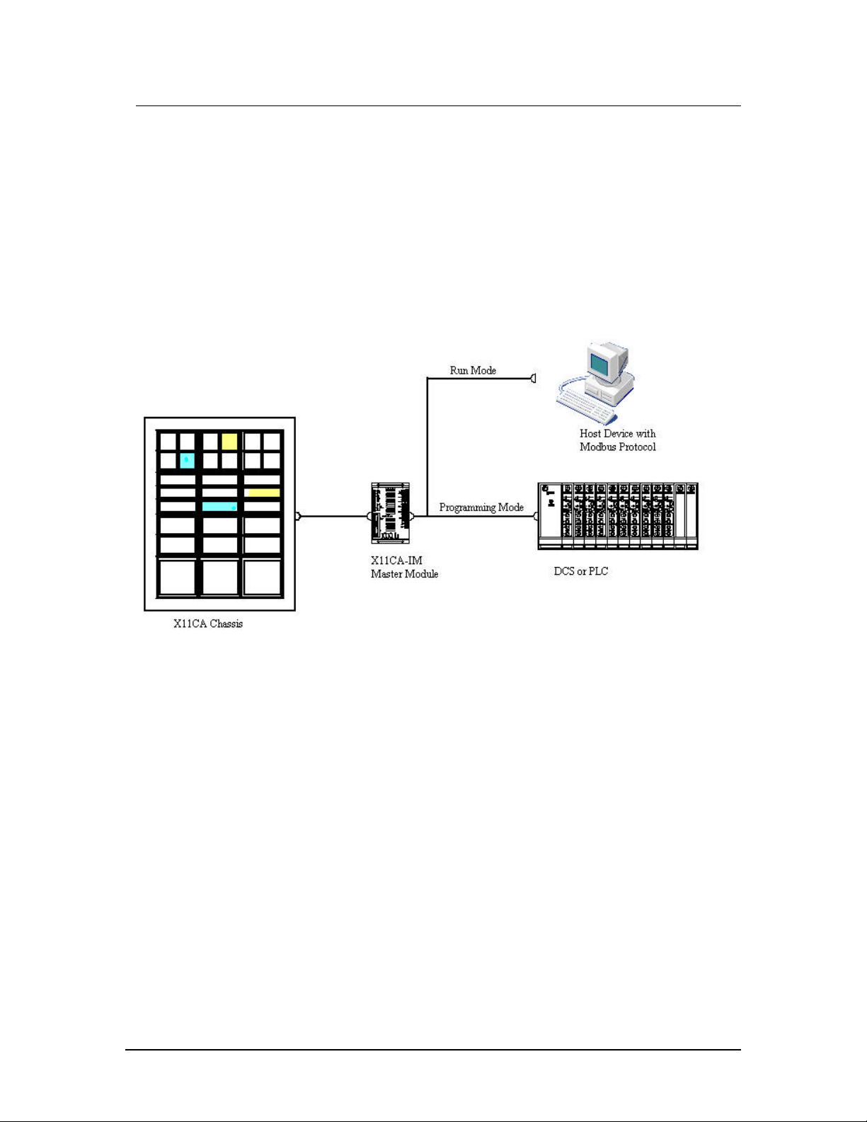
The RONAN Series X11CA Computer Annunciator system is a state of art annunciator
group system, designed to provide the most advanced data acquisition and monitoring
system that meet the requirement of the process and power industries in the most
economic way.
The X11CA-Interface Module of the system provides advanced communication
protocols to interface the external host computer, local network or plant network. For
field contact repeater or remote group alarms it utilizes common trouble alarm and
auxiliary relay outputs.
The followings are some of its key features.
§ The system is offered in both the Window Annunciator model and the Remote
Chassis model.
§ The Window Annunciator model feature Monalarm, Binalarm, Trialarm and
Quadalarm within Ronan’s standard 3.5 inch (89mm) by 3.5-inch (89mm)
mechanical cabinet modules.
§ The Remote Logic system features high density input field contact capacity with
remote light indicators.
§ Each single plug-in module is internally expandable from one to four input
channels and Monalarm, Bialarm, Trialarm and Quadalarm display units.
§ It utilizes the state of art technology, Philips micro-controller.
§ It holds up to four input alarm circuitry of high-speed conventional CMOS
integrated circuit solid-state design with maximum noise immunity and reliability.
§ The polarity of each field contact is set as normally open or closed using jumper
switch for each channel.
§ The most popular industry-wide sequences of ISA, such as A-1, A-4, A-5, A-6,
F1A, F1M-1, F2A-1, F2M-1, F3A-1, and M-1 are available.
§ It is powered by external 24VDC power supply.
Hardware Control-© 2002 Ronan Engineering 1
Page 6
Rev 1.0 Series X11CA Hardware Manual
1. Overview
§ The maximum of 256 modules are allowed per system.
§ Microprocessor Based system
§ High noise immunity
§ Field proven off-the shelf worldwide
§ Serial input/output
§ Comprehensive user configuration with standard windows software
1.1 Abbreviations
GF : Global Function
CTA /CA : Common Trouble Alarm
FC : Field Contact
MEIN : First Out
AUX : Auxiliary Relay
TO : Transistor Output
H1 : Horn 1
H2 : Horn 2
NC
TCP : Transport Control Protocol.
IP : Internet Protocol
DWG NO : Drawing Number
Figure 1-1 X11CA System
: Not Connected
Hardware Control-© 2002 Ronan Engineering 2
Page 7
Rev 1.0 Series X11CA Hardware Manual
1. Overview
1.2 Revision History
Revision 0.1 : First Draft
Revision 0.2 : Second Draft
Revision 1.0 : First approved and released document
1.3 References
QA400 : Design Control
QA4000
QA4500
X11CA-3000
X11CA-3001-IOM
1.4 Specifications and Power Requirements
1.4.1 System Voltage
: Design Development Quality Assurance Plan
: Project Archive
: X11CA-IM Master Modules
: X11CA Configuration Software User’s Manual
§ Lamps, Logic – 24 Vdc ± 20%
§ Field contacts – 24 Vdc, 48 Vdc, 125 Vdc, 115 Vac, or 240 Vac
1.4.2 Power Source (System External)
§ Power Supply – 115 Vac 50/60 Hz; 240 Vac 50/60 Hz
§ Converter – 24 Vdc, 48 Vdc, or 125 Vdc
To specify the correct power supply, count the number of alarm modules
you need to power from the supply. Calculate the total requirements as
follows.
Total Watts = Number of Modules x Factor F + (F Aux.) + P (IM)
F Aux.
Model F Lamps F LEDs
Relay
Adder
P (IM)
X16PDM 10.5 W 7.0 W 4 W 10 W
Match the total wattage with the next higher power rating of the Power
Supply or Converter listed.
Hardware Control-© 2002 Ronan Engineering 3
Page 8

Rev 1.0 Series X11CA Hardware Manual
1. Overview
1.4.3 Temperature Range
§ Operating – 0° to 60° C (32° to 140° F)
§ Storage - -40° to +85° C (-40° to + 185° F)
1.4.4 Inputs
§ Contact – Dry or Live; Normally Open / Normally Closed
§ Field Selectable
§ Interrogation Voltage – 24 Vdc, 48 Vdc, 125 Vdc, 115 Vac, or 240
Vac
1.4.5 Response Time
§ 20 Milliseconds by default. It can be modified using the X11CA
Configuration software.
1.4.6 EMI/RFI Compatibility
§ CE Compliant
1.4.7 Outputs
§ Visual – Fast Flash, Slow Flash, Steady ON, Intermittent Fast Flash
§ Audible – Dual, Selectable by Cabinet Module
§ Auxiliary Relays – Form C, Selectable Form A or B; Normally not
Energized or Normally Energized
§ Contact Rating – General Purpose: 1 Amps @ 28 Vdc; 0.65 Amp @
115 Vac
§ Common System Trouble – Form C, 2 Amps @ 28 Vdc; 0.65 Amp @
115 Vac – Open Collector Transistor Output 200 mA @ 28 Vac
§ Common System Reflash – Form C, 2 Amps @ 28 Vdc; 0.65 Amp @
115 Vac – Open Collector Transistor Output 200 mA @ 28 Vac
1.4.8 Controls
§ Momentary Push Button: Integral or Remote; Single Pole
§ Normally Open; +V Switched; Silence; Acknowledge; Reset, Test,
GP1, GP2
1.4.9 Diagnostic
§ System Trouble Alarm (RUN) – Form C, 2 Amps @ 28 Vdc; 0.65
Amp @ 115 Vac
§ System Trouble Alarm (RUN) – Indicating LED Green
§ Communication Diagnostic (ERROR) – Indicating LED Red
§ Transmit/Receiver LED Pair
Hardware Control-© 2002 Ronan Engineering 4
Page 9

Rev 1.0 Series X11CA Hardware Manual
1. Overview
1.4.10 Communications
§ Serial – RS485 (P1) to External Host
§ Network – RJ45 (TCP/IP) to External Host
1.4.11 Serial Protocols
§ MODBUS RTU, Allen Bradley, DF1, DNP 3.0, Ronan Proprietary
1.4.12 Network Protocols
§ TCPIP (OPC)
1.4.13 Serial
§ RS232 (P2) – System Sequence and Option Programming via Laptop
or Computer
§ Software – Ronan X11CA Configuration
1.4.14 Special Feature
§ Alarm Storage – 256 Alarm modules with four alarm points each
§ GP1, GP2 – Special Function Push-button Interface
1.4.15 System Size
§ Basic Cabinet Module – 3.50 inch (88.90 mm) x 3.50 inch (88.90 mm)
1.4.16 System Weight
§ Per Cabinet Module – 1.75 pounds (0.79 kg), Not Including Power
Supply
1.4.17 Warranty
§ Three years
1.4.18..Approvals(Pending)
§ UL: Underwriters Laboratories
§ CE: Cenelec
• CUL: Canadian Underwriters Laboratories
Hardware Control-© 2002 Ronan Engineering 5
Page 10

Rev 1.0 Series X11CA Hardware Manual
2. X11CA Hardware Setup
2. X11CA Hardware
The RONAN X11CA Computer Annunciator System with microprocessor based
electronics is assembled from basic 3.50 inch (88.90 mm) by 3.50 inch (88.90 mm)
modules to make up the overall size requirements and number of windows required.
The mechanical modules assembled from aluminum castings and extrusions provide
excellent heat dissipation for a continuously lit annunciator system and feature the
structural strength required in industrial applications.
The rear terminal is designed as a single piece molded plastic assembly per window
for durability. A small 4.00 inch (101.60 mm) wide x 6.00 inch (152.40 mm) deep x
1.00 inch (25.40 mm) high module (interface module) is provided to connect the
system to an external host.
2.1 X11CA Annunciator Display Modules
The X11CA Annunciator module allows field programmable selections of all
commonly used ISA sequences from a host computer.
The lamp display of each module can have single, dual, triple or quad alarm
channel alarm logic displays, and field contact polarity of each channel is selected
by setting the jumpers on the board.
2.1.1 Display and Name Plates
The colored nameplates can be supplied in five standard colors, (red, green,
amber, white, and blue) to distinguish such functions as fire alarm or shut
down…etc.
The Sandwich nameplates, an option exclusive to RONAN Visual Annunciator,
are generally supplied with white front lenses and colored back lenses. This
lens combination displays all windows white in non-lit status, changing to the
selected color in OFF normal condition. The Sandwich nameplates are for
lamps only.
Each lamp cell uses dual bulbs with 1 watt each, except Quadalarm.
Hardware Control-© 2002 Ronan Engineering 6
Page 11

Rev 1.0 Series X11CA Hardware Manual
2. X11CA Hardware Setup
Page Intentionaly Left Blank
Hardware Control-© 2002 Ronan Engineering 7
Page 12

Rev 1.0 Series X11CA Hardware Manual
2. X11CA Hardware Setup
Page Intentionaly Left Blank
Hardware Control-© 2002 Ronan Engineering 8
Page 13

Rev 1.0 Series X11CA Hardware Manual
2. X11CA Hardware Setup
Page Intentionaly Left Blank
Hardware Control-© 2002 Ronan Engineering 9
Page 14

Rev 1.0 Series X11CA Hardware Manual
2. X11CA Hardware Setup
2.1.6 Quadalarm Module: Part NO: X11CA-4000
The four windows Quadalarm Module represent the highest density of
annunciation in the X11CA series. The 1.40 inch (35.56 mm) high by 1.40
inch wide window is illuminated by two 1-watt lamps or LED indicators.
Hardware Control-© 2002 Ronan Engineering 10
Page 15
Rev 1.0 Series X11CA Hardware Manual
2. X11CA Hardware Setup
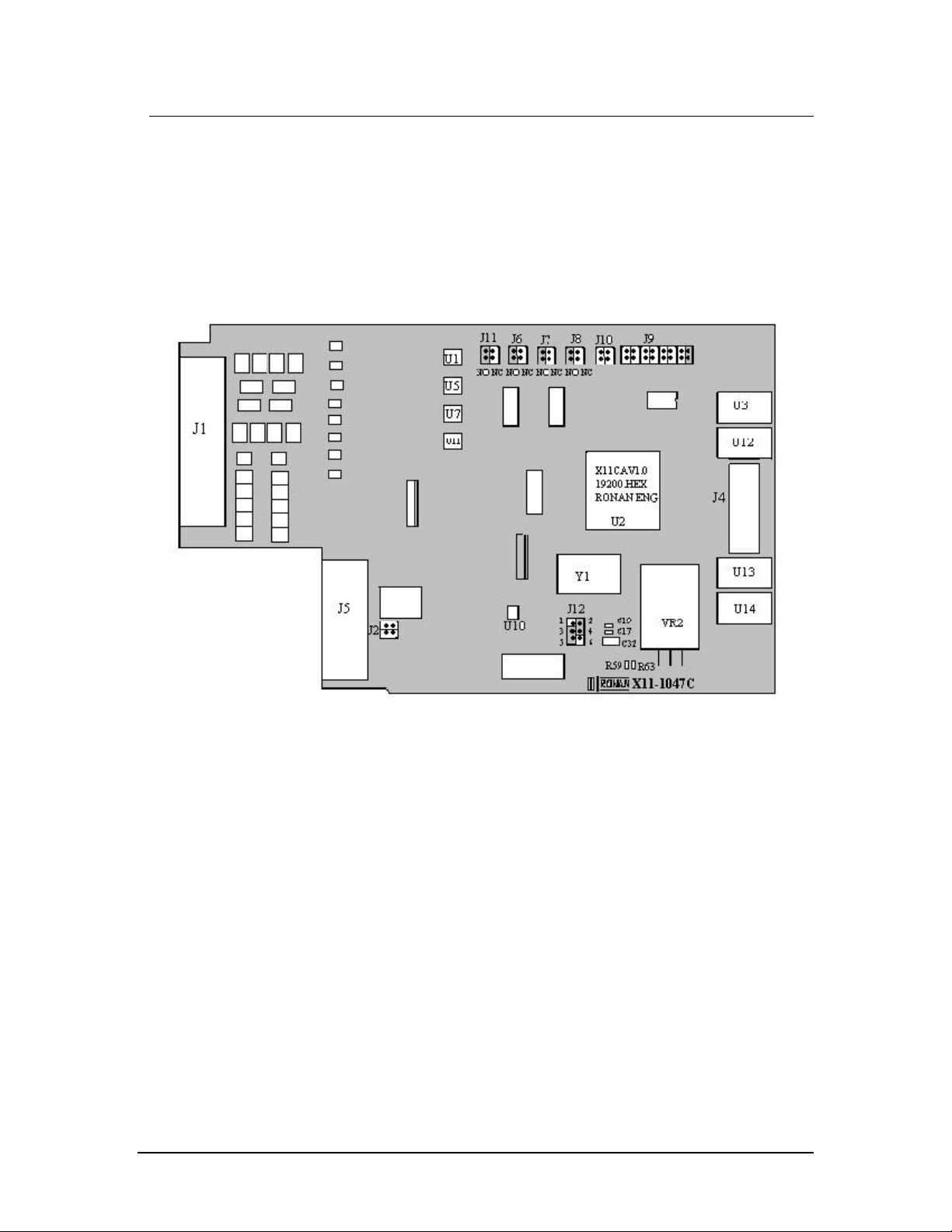
2.2 X11CA Alarm Module: Part NO. X11-1047
Figure 2-7 X11-1047C Module
2.2.1 Power Sources
The external 24 VDC power is supplied to the V+ jumper connector J5 (pin
7,15) and to the V- jumper connector J5 (pin 8,16) on the PC board.
The voltage regulator, VR2, and two resistors, R59 and R63, on the board
reduce the voltage down to 5 VDC.
The electrolytic capacitor, C32, and two ceramic capacitors, C17 and C19,
keep the voltage constant for load variations and voltage transients.
Hardware Control-© 2002 Ronan Engineering 11
Page 16

Rev 1.0 Series X11CA Hardware Manual
2. X11CA Hardware Setup
2.2.2 Field Contact Inputs
Field contacts can be set as normally open or normally closed by setting
jumper switches (J11, J6, J7, and J8) either as NO or NC on each alarm
module.
• Dry contact – The system internal interrogation powered 24 Vdc.
• Live contact – 0pto-isolated inputs. The opto-couplers, U1, U5, U7 and
U11, provide 2,500-volt isolation.
• 24 Vdc, 48 Vdc, 125 Vdc or 115 Vac, 240 Vac
2.2.3 Micro controller (U2)
U2 is a Single-Chip 8-Bit Micro controller manufactured in advanced CMOS process
and is a derivative of the 80C51 flash micro controller family.
The device contains a non-volatile 32KB Flash program memory that is serial In
Application programmable. That means the micro controller fetches a new program
code and reprograms itself while the applicat ion is running in the system.
After the serial connection is made between the host computer and the X11-1047
Alarm module via the X11CA -IM (Refer to the Figure 2-17 X11CA-2000 Rear
Terminal Wiring Diagram), the X11CA configuration software on the host computer
uses IAP for the remote programming to erase and reprogram the content of the Flash
Memory. (For reprogramming the Micro controller see X11CA Software Manual).
It is synchronized by the clock generator (Y1) that generates 18,432 MHz oscillations.
2.2.4 Outputs
• Auxiliary Output Signals:
These signals provide open collector outputs to the energized relays on the
auxiliary modules, and it is programmable for various system functions.
• Transistor Output: Transistor output provides an open collector output
(pulling to V), and it is programmable for various system functions. A
typical application is to drive an auxiliary relay following the field contact
or lamp logic.
• Lamp Drivers (U3, U12, U13, U14): Lamp drivers are designed to operate
at 70V (1A) with over voltage, over temperature and short circuit
protection.
Hardware Control-© 2002 Ronan Engineering 12
Page 17

Rev 1.0 Series X11CA Hardware Manual
2. X11CA Hardware Setup
2.2.5 RS485 Network
The X11CA Annunciator uses a typical RS-485 four-wire multidrop
configuration system. All slave modules communicate with the master module,
X11CA IM only, and the address of each slave module is selectable by the
jumper, J9, using the binary code.
Jumper 9
Each X11CA module board must have a unique binary address to
communicate with the X11CA Configuration program and the X11CAIM. This address is determined by setting the jumper, J9.
Refer to the conversion table on page 40 to convert from 000000012 to
1111 1111
Jumper 9 of Appendix B: Data Conversion (Bin to Dec)
10.
Table shows the switch setting for 00000001
The RS485 driver, U10, is used as a RS485 to TTL converter.
2.
2.2.6 Input Response Time
The default response time of each point is 20 milliseconds, but it can be
modified using the X11CA operating software.
2.2.7 Summary of Jumper Settings
Jumper
NO.
J1 Connector to the Terminal board (Module No. X11C451)
J2 RS485 terminator. If both top and bottom pins are
J3 Not Available
J4 Connector to the front panel of the Lamp board (Module No.
J5 Connector to the Communication module (Module No. X11-
J6 Polarity of field input contact B. Either Normally Open or
J7 Polarity of field input contact C. Either Normally Open or
J8 Polarity of field input contact D. Either Normally Open or
Description Default
connected, RS485 termination will be enabled.
X11-1038)
1033)
Normally Closed.
Normally Closed.
Normally Closed.
Settings
No connection
except the first
alarm module
NO or NC.
NO or NC.
NO or NC.
Hardware Control-© 2002 Ronan Engineering 13
Page 18

Rev 1.0 Series X11CA Hardware Manual
2. X11CA Hardware Setup
J9 Address of the alarm modul e. Each alarm module must have
a unique address number.
For the address setting, refer to the Appendix B: Data
J10 Used for activating the boot trap loader during the first
programming time into the firmware
J11 Polarity of field input contact A. Either Normally Open or
Normally Closed.
J12 Converter from R485 to TTL for Receiver and
Transmission.
§ Receiver: If pin 1 and 3 are connected, the
converter is enabled by the micro-controller (U2).
If pin 3 and 5 are connected, it is always enabled.
§ Transmission: If pin 2 and 4 are connected, the
converter is enabled by the micro-controller (U2).
If pin 4 and 6 are connected, it is always enabled.
Figure 2-8 Summary of the X11-1047 Jumper Settings
Conversion (Bin to Dec) Table on page 40.
See the
Appendix B:
Data
Conversion
(Bin to Dec)
Table
Not connected
NO or NC
Receiver: pin 3
and 5 are
connected.
Transmission:
pin 2 and 4 are
connected.
2.3 Auxiliary Contact Module: Part NO. X11-1049
The auxiliary contact module is available with a single, dual, triple, or quad relay
circuit, accommodating the window density selected. The modules can be plugged in
the front of the system and may be purchased initially or added later. The terminals
for the contact outputs are furnished as a part of the system. Each relay provides a
selectable form A or B type contact with a rating of 2A at 28 Vdc. Normally open
(Type A) or normally closed (Type B) contact is available for each alarm point at
their respective rear terminal block terminals 5 and 6. The normal operation (NO/NC)
can be changed on the auxiliary contact module at headers marked AUX1, AUX2,
AUX3, or AUX4.
WARNING:
Before setting up the X11CA system, make sure that power to the system is
completely off.
Hardware Control-© 2002 Ronan Engineering 14
Page 19

Rev 1.0 Series X11CA Hardware Manual
2. X11CA Hardware Setup
2.4 Cables
Figure 2-9 Jumper Setting on the Quad Relay Circuit
2.4.1 X11CA to X11CA-IM without PB
Figure 2-10 Cable for X11CA to X11CA-IM Connection
2.4.2 X11CA-IM (P2) to PC (RS232)
Hardware Control-© 2002 Ronan Engineering 15
Page 20

Rev 1.0 Series X11CA Hardware Manual
2. X11CA Hardware Setup
Figure 2-11 RS232 Cable from Host PC to X11CA-IM Connection
2.5 Mounting
Refer the mounting diagrams on the enclosed CD ROM, X11CA Drawings and
Sequence Chart, for detail.
2.5.1 Mounting the Modules in the Alarm Cabinet
The annunciator is shipped with all of the alarm/lamp modules, auxiliary
contact module(s) and flasher module(s) installed in the cabinet, as specified
by purchase order.
External horn relay(s), reflash relay, common alarm relay, relay sockets are
packed separately.
2.5.2 Mounting the Alarm Cabinet to the Panel
1. Position the X11CA alarm cabinet into the cutout hole on the panel.
Figure 2-12 Cutout area of the panel
Hardware Control-© 2002 Ronan Engineering 16
Page 21

Rev 1.0 Series X11CA Hardware Manual
2. X11CA Hardware Setup
Page Intentionaly Left Blank
Hardware Control-© 2002 Ronan Engineering 17
Page 22

Rev 1.0 Series X11CA Hardware Manual
2. X11CA Hardware Setup
Page Intentionaly Left Blank
Hardware Control-© 2002 Ronan Engineering 18
Page 23

Rev 1.0 Series X11CA Hardware Manual
2. X11CA Hardware Setup
2.6 Wiring Instructions
The following diagrams show rear terminal arrangement and wiring for the X11CA2000 system and the X11CA-4000 system. For other wiring diagrams, refer to the
wiring diagrams on the CD.
2.6.1 X11CA-2000 Rear Terminal Arrangement and Wiring
Figure 2-17 X11CA-2000 Rear Terminal Wiring Diagram
Hardware Control-© 2002 Ronan Engineering 19
Page 24

Rev 1.0 Series X11CA Hardware Manual
2. X11CA Hardware Setup
2.6.2 X11CA-4000 Rear Terminal Arrangement and Wiring
Figure 2-18 X11CA-4000 Rear Terminal Wiring Diagram
Hardware Control-© 2002 Ronan Engineering 20
Page 25

Rev 1.0 Series X11CA Hardware Manual
:
:
:
:
:
:
:
:
:
:
:
:
:
:
:
:
2. X11CA Hardware Setup
Figure 2-19 Typical transistor input (DWG NO: X11C497)
(H)
(FC)
(ME)
Field contact voltage for dry contact
Field contact return
Connect all First out windows in a
group.
(TO)
AUX OUT
Transistor output driver.
Auxiliary output - N.O./N.C. selectable
T.O.: A1, A2, CTA, RFL, RUN for
transistor driver
A1, A2, CTA, RFL, RUN for auxiliary
output
NO
COM
NC
A1
A2
CTA
RFL
RUN
GP1, GP2
Normally opened
Common
Normally closed.
Horn 1
Horn 2.
Common Trouble Alarm
Reflash
X11CA-IM power indication
Programmable inhibit function.
Hardware Control-© 2002 Ronan Engineering 21
Page 26

Rev 1.0 Series X11CA Hardware Manual
2. X11CA Hardware Setup
Alarm Terminal Inputs
Two basic types of terminal contacts are available.
i. Dry contact.
Figure 2-20. With 24Vdc
system power
Figure 2-21. With 48Vdc,
5Vdc, 10Vdc, 125Vdc FC
Source
FC source must be common to
the system FC.
ii. Opto-Coupled (Live contact)
Figure 2-22. With FC source
24 Vdc/Vac, 48Vdc/Vac,
120/Vac
Each active alarm input must be wired to a customer’s sensing device to set
its alarm condition as either open or closed. The terminals on the alarm
system for each alarm input are marked H and FC. The H terminal in the
standard alarm system is the main system voltage that is supplied via a pullup resistor on each alarm point. Each alarm input module is provided with a
separate H terminal. When using a common H, it is important to jumper
together the H terminals of the respective alarm cabinet modules to provide
the correct amount of current source to the field contact.
Hardware Control-© 2002 Ronan Engineering 22
Page 27

Rev 1.0 Series X11CA Hardware Manual
2. X11CA Hardware Setup
The return wire from the field contact is wired to the FC terminal on each
respective alarm module. Since the alarm system provides the power to the
field contacts, it is important to verify that no other voltage source is present
on either the H or FC terminals.
NOTE:
Please refer to the transmitter drawing on the enclosed CD.
In general, the solid-state alarm system is a floating system. The V+ and Vshould be verified as ungrounded
Power Supply
Verify the polarity of connection to the alarm systems.
In large systems, verify that the wire sizes are efficient for high current use
of the power leading to the alarm cabinets. To protect the larger alarm
chassis, it is common to provide more than one input to the cabinet in
which each section is provided with a separate filter, fuse and supply input
terminals.
Converters
1.. DC to DC Converter
Model - Power Failure,
Circuit Breaker, Power ON
Light, Diode Gated
125-125-125--
24/125
24/125
24/125
24/125
48--
24/125
48-48
24/125
--
DC Voltage In
-- 150SCP
-- 300SCP
-- 600SCP
-- 150SCP
-- 300SCP
600
--
DC Voltage Out
SCP
Power Output Watts
Hardware Control-© 2002 Ronan Engineering 23
Page 28

Rev 1.0 Series X11CA Hardware Manual
2. X11CA Hardware Setup
2.. AC to DC Converter
115 - 24 - 125
115 - 24 - 250
115 - 24 - 375
116 - 24 - 500
115 - 24 - 750
220 - 24 - 125
220 - 24 - 250
220 - 24 - 375
220 - 24 - 500
220 - 24 - 750
115 - 24/125 - 125
115 - 24/125 - 250
115 - 24/125 - 375
115 - 24/125 - 500
115 - 24/125 - 750
115 - 24 - 250DA
115 - 24 - 375DA
115 - 24 - 500DA
115 - 24 - 750DA
Diode Grated Output
Power Output Watts
DC Voltage Out
AC Voltage In
In case of multiple supply of input, make the parallel V+ and Vconnections.
2.7. Power Up
Inspect the hookup wiring to insure conformity with the schematic provided. Verify
that ME terminals are connected to other ME terminals only.
Turn the power on.
Hardware Control-© 2002 Ronan Engineering 24
Page 29

Rev 1.0 Series X11CA Hardware Manual
2. X11CA Hardware Setup
Upon the power application, the flasher module within the system will automatically
initiate reset cycle. If all the associated field contacts are in normal condition, the
system should then be in a quiescent state with the horn(s) off and no lamps flashing.
Press the TEST button.
(Refer to the sequence charts on the CD for the expected results.)
2.8 Troubleshooting
2.8.1 General
§ No light – Check for the burned out, broken or improperly seated bulbs.
§ Not functioning alarm points – Make sure that the alarm modules are
properly seated in their connector.
§ Power supply fuse blows each time power is applied.
a. Check the Power Supply Parts List or the unit instrument tag for
proper fuse size.
b. Remove the alarm system from the supply and try again. If fuse
holds, double check polarity and reconnect. If the fuse still blows,
remove all alarm modules and flasher and try again. If the fuse blows
at this point, the problem has been isolated to a short in the internal
wiring.
2.8.2. Non-operating Alarm System
§ Verify that the power source is functioning properly/
§ The plus to minus voltage on the rear terminals is in the range of 18V to
28V.
§ Verity each polarity.
2.9 Dimension
Refer to the files saved on the enclosed CD ROM, X11CA Drawings and Sequence
Chart, for other dimensions.
Hardware Control-© 2002 Ronan Engineering 25
Page 30

Rev 1.0 Series X11CA Hardware Manual
2. X11CA Hardware Setup
2.9.1 . Models X11CA-RelayRack Mounted Series-4000
Figure 2-23 X11CA-RR
Hardware Control-© 2002 Ronan Engineering 26
Page 31

Rev 1.0 Series X11CA Hardware Manual
2. X11CA Hardware Setup
Figure 2-24 Dimensional Information of X11CA RR-4000
(DWG NO. X11C513)
Hardware Control-© 2002 Ronan Engineering 27
Page 32

Rev 1.0 Series X11CA Hardware Manual
3. Event Sequences
3. Event Sequences
Typical alarm sequence specification for the X11CA is as follows.
Figure 3-1 Typical Alarm Sequence Specifications.
3.1 Options
The following list has the types of options used for the X11CA.
Hardware Control-© 2002 Ronan Engineering 28
Page 33

Rev 1.0 Series X11CA Hardware Manual
3. Event Sequences
Options Descriptions
1. Silence Pushbutton:
A separate pushbutton is added to allow silencing the alarm audible
device without affecting the visual displays.
4 No Lock-in:
5 No Flashing:
6 No Alarm Audible
No outputs on Terminals A1 and A2.
Figure 3-2 Silence Pushbutton Option
Figure 3-3 No Lock-in Option
3.2 Basic Sequence Types
The descriptions of the basic sequence types are listed below. Variations in the
basic sequences are defined by adding the options numbers to the basic sequences.
Hardware Control-© 2002 Ronan Engineering 29
Page 34

Rev 1.0 Series X11CA Hardware Manual
3. Event Sequences
A Automatic Reset:
The sequence returns to the normal state automatically, after the event
returns to normal and acknowledged.
M Manual Reset:
The sequence returns to the normal state, after the event returns normal,
acknowledged, and reset.
3.3 First-out Sequence
First out sequences indicate which one of a group of alarm points operated first.
To accomplish this, the visual display of the first alarm event must be different
from the visual display of the subsequent alarm events in that group. Only one
first out alarm event can exist in the group. The first out sequences are designated
by a combination of the first out designation, the basic sequence letter, and the
option numbers.
F1 No subsequent Alarm State:
The F1 family of sequences differentiates the first alarm event of the
group from the subsequent events by flashing its lamp and activating its
horn. Clearing of the first alarm event allows the system to accept the
next alarm in the group as the First out.
F2 No subsequent Alarm Flashing:
The F2 family resets the first out alarms with the operation of the
Acknowledge pushbutton. The first out alarm and subsequent alarms
operate as the F1 family. Clearing of the first alarm event allows the
system to accept the next alarm in the group as the First out.
F3 First Out Flashing and Reset Pushbutton:
Additional types of flashing are added to identify new and
acknowledged first alarms. A first out reset pushbutton is added to reset
the first alarms, whether the event has returned to normal or not.
Hardware Control-© 2002 Ronan Engineering 30
Page 35

Rev 1.0 Series X11CA Hardware Manual
3. Event Sequences
3.4 Sequences of X11CA
3.4.1 A-1
Automatic Reset
The audible device is silenced and flashing stops when acknowledged.
Acknowledgement of the alarm resets automatically when the event returns to
normal.
Hardware Control-© 2002 Ronan Engineering 31
Page 36

Rev 1.0 Series X11CA Hardware Manual
3. Event Sequences
3.4.2 F1A-1
First Out with Automatic Reset
The First Alarm operates as a basic sequence A. Subsequent alarms operate as a
status lamp. The visual display of the subsequent alarms is steady on until the
events return to normal, at which time the lamplights go off.
Key applications:
1. If First out is the only alarm of importance.
2. Current status of the subsequences is of interest.
3. Minimum operator action is preferred for the subsequent alarms.
4. Subsequent alarms must lock-in and be annunciated by audible and
visual flashing, see sequence F3A.
Hardware Control-© 2002 Ronan Engineering 32
Page 37

Rev 1.0 Series X11CA Hardware Manual
3. Event Sequences
3.4.3 F1M-1
First out with manual reset
The first alarm operates as a basic sequence M. Subsequent alarms operate as a
status lamp that locks in until the events return to normal and Reset is initiated.
Hardware Control-© 2002 Ronan Engineering 33
Page 38

Rev 1.0 Series X11CA Hardware Manual
3. Event Sequences
3.4.4 F2A -1
First out automatic reset.
The first alarm operates as a basic Sequence A. subsequent alarms operate as a
status lamp and also activates the audible devices. Option 1 must be used to
enable the apparent operation of the audible for subsequent alarms. Subsequent
alarms are locked-in and cannot return to the normal state until the Acknowledge
pushbutton is activated, resetting the first out-alarm. After the inputs return to
normal and acknowledgement, all input points return to the normal sequence state
automatically.
Key applications:
1. First-out Alarm is of prime importance.
2. Subsequent alarms must lock-in and resound the audible if it has been
silenced.
3. If Option 1 is used, the number of concurrent alarms expected is small
enough that flashing is not required to locate each new subsequent
alarm when the audible sounds.
Hardware Control-© 2002 Ronan Engineering 34
Page 39

Rev 1.0 Series X11CA Hardware Manual
3. Event Sequences
3.4.5 F2M-1
First Out Manual Reset
The First out alarm operates as a basic sequence M. Subsequent alarms operate as
a status lamp and also operate the audible. Before acknowledging the First out
alarm, sequence F2M operates the same as sequence F2A. After
acknowledgement, sequence F2M differs by requiring a Reset to return to normal
even though the events have returned to normal.
Hardware Control-© 2002 Ronan Engineering 35
Page 40

Rev 1.0 Series X11CA Hardware Manual
3. Event Sequences
3.4.6 F3A-1
First out.
Displaying the visual device in intermittent flashing pattern and activating the
audible devices until the first function is reset distinguish the first alarm. The
acknowledged first alarm is distinguished by changing the visual display as slow
flashing. Subsequent alarms follow the basic sequence A. Because the Reset
pushbutton is used to reset the first out function, Acknowledge can be used to
sequence the subsequent alarms through a standard sequence. This makes it
possible to distinguish the new subsequent alarms from the previously
acknowledg ed subsequent alarms. Also the subsequent alarms lock in until they
are acknowledged. Once acknowledged, they can automatically return to normal
state when the input points return to normal.
Hardware Control-© 2002 Ronan Engineering 36
Page 41

Rev 1.0 Series X11CA Hardware Manual
3. Event Sequences
3.4.7 F3M-1
First out manual reset.
The first out alarm in a group is distinguished by unique display until the first out
function is reset. Because Acknowledge is not used to reset the first out function,
the new first alarm and subsequent alarms can be acknowledged so that the new
alarms can be distinguished from the previously acknowledged alarms. The
subsequent alarms return to normal state only if they are in the normal state when
the Reset is operated and the first out group has been reset.
Hardware Control-© 2002 Ronan Engineering 37
Page 42

Rev 1.0 Series X11CA Hardware Manual
3. Event Sequences
3.4.8 M-1
Manual Reset
Sequence M is a basic alarm sequence (Horn on with Flashing Visual) with
Manual Reset that retains acknowledged alarms until the process input conditions
return to normal and the manual Reset pushbutton is activated. In some
applications, Sequence M may have a disadvantage since new alarms that occur
while the Acknowledge Pushbutton is being operated appear in the steady on
condition. Any alarm occurring during the Acknowledge pushbutton operation
may be confused with existing acknowledged alarms. In order to reset alarms,
sequence M requires that the Reset pushbutton be operated repeatedly to
determine if the process input conditions have returned to normal. Use of Options
1 and 2 improves the sequence of for reviewing new incoming alarms.
Hardware Control-© 2002 Ronan Engineering 38
Page 43

Rev 1.0 Series X11CA H ardware Manual
4. Appendix A: List of Figures
4. Appendix A: List of Figures
FIGURE 1-1 X11CA SYSTEM ............................................................................................... 2
FIGURE 2-6 QUADALARM PLUG IN MODULE....................................................................... 11
FIGURE 2-7 X11-1047C MODULE ..................................................................................... 11
FIGURE 2-8 SUMMARY OF THE X11-1047 JUMPER SETTINGS ............................................ 14
FIGURE 2-9 JUMPER SETTING ON THE QUAD RELAY CIRCUIT............................................ 15
FIGURE 2-10 CABLE FOR X11CA TO X11CA-IM CONNECTION........................................ 15
FIGURE 2-11 RS232 CABLE FROM HOST PC TO X11CA-IM CONNECTION....................... 16
FIGURE 2-12 CUTOUT AREA OF THE PANEL........................................................................ 16
FIGURE 2-13 THE FRONT VIEW OF THE CABINET.............................................................. 17
FIGURE 2-14 ASSEMBLING THE CLAMP PARTS.................................................................. 17
FIGURE 2-15 INSERTING THE C LAMP INTO THE TOP CENTER OF THE CABINET GROOVE.... 17
FIGURE 2-16 DETAIL A ...................................................................................................... 18
FIGURE 2-18 X11CA-4000 REAR TERMINAL WIRING DIAGRAM...................................... 20
FIGURE 2-19 TYPICAL TRANSISTOR IN PUT (DWG NO: X11C497).................................... 21
FIGURE 2-20. WITH 24VDC SYSTEM POWER ...................................................................... 22
FIGURE 2-21. WITH 48VDC, 5VDC, 10VDC, 125VDC FC SOURCE.................................... 22
FIGURE 2-22. WITH FC SOURCE 24 VDC/VAC, 48VDC/VAC, 120/VAC............................. 22
FIGURE 2-23 X11CA-RR .................................................................................................. 26
FIGURE 2-24 DIMENSIONAL INFORMATION OF X11CA RR-4000...................................... 27
FIGURE 3-1 TYPICAL ALARM SEQUENCE SPECIFICATIONS................................................. 28
FIGURE 3-2 SILENCE PUSHBUTTON OPTION....................................................................... 29
FIGURE 3-3 NO LOCK-IN OPTION....................................................................................... 29
Hardware Control-© 2002 Ronan Engineering 39
Page 44

Rev 1.0 Series X11CA Hardware Manual
5. Appendix B: Data Conversion (Bin to Dec) Table
5. Appendix B: Data Conversion (Bin to Dec) Table
The following list shows numbers from 0000 00012 (110) to 1111 11112 (255
SW8 SW7 SW6 SW5 SW4 SW3 SW2 SW1 Binary Address
OFF OFF OFF OFF OFF OFF OFF ON 0000 0001 1
OFF OFF OFF OFF OFF OFF ON OFF 0000 0010 2
OFF OFF OFF OFF OFF OFF ON ON 0000 0011 3
OFF OFF OFF OFF OFF ON OFF OFF 0000 0100 4
OFF OFF OFF OFF OFF ON OFF ON 0000 0101 5
OFF OFF OFF OFF OFF ON ON OFF 0000 0110 6
OFF OFF OFF OFF OFF ON ON ON 0000 0111 7
OFF OFF OFF OFF ON OFF OFF OFF 0000 1000 8
OFF OFF OFF OFF ON OFF OFF 0N 0000 1001 9
OFF OFF OFF OFF ON OFF ON OFF 0000 1010 10
OFF OFF OFF OFF ON OFF ON ON 0000 1011 11
OFF OFF OFF OFF ON ON OFF OFF 0000 1100 12
OFF OFF OFF OFF ON ON OFF ON 0000 1101 13
OFF OFF OFF OFF ON ON ON OFF 0000 1110 14
OFF OFF OFF OFF ON ON ON ON 0000 1111 15
OFF OFF OFF ON OFF OFF OFF OFF 0001 0000 16
OFF OFF OFF ON OFF OFF OFF ON 0001 0001 17
10).
Decimal
Equivalent
OFF OFF OFF ON OFF OFF ON OFF 0001 0010 18
OFF OFF OFF ON OFF OFF ON ON 0001 0011 19
OFF OFF OFF ON OFF ON OFF OFF 0001 0100 20
OFF OFF OFF ON OFF ON OFF ON 0001 0101 21
OFF OFF OFF ON OFF ON ON OFF 0001 0110 22
OFF OFF OFF ON OFF ON ON ON 0001 0111 23
OFF OFF OFF ON ON OFF OFF OFF 0001 1000 24
OFF OFF OFF ON ON OFF OFF 0N 0001 1001 25
OFF OFF OFF ON ON OFF ON OFF 0001 1010 26
OFF OFF OFF ON ON OFF ON ON 0001 1011 27
OFF OFF OFF ON ON ON OFF OFF 0001 1100 28
OFF OFF OFF ON ON ON OFF ON 0001 1101 29
OFF OFF OFF ON ON ON ON OFF 0001 1110 30
Hardware Control-© 2002 Ronan Engineering 40
Page 45

Rev 1.0 Series X11CA Hardware Manual
5. Appendix B: Data Conversion (Bin to Dec) Table
SW8 SW7 SW6 SW5 SW4 SW3 SW2 SW1 Binary Address
OFF OFF OFF ON ON ON ON ON 0001 1111 31
OFF OFF ON OFF OFF OFF OFF OFF 0010 0000 32
OFF OFF ON OFF OFF OFF OFF ON 0010 0001 33
OFF OFF ON OFF OFF OFF ON OFF 0010 0010 34
OFF OFF ON OFF OFF OFF ON ON 0010 0011 35
OFF OFF ON OFF OFF ON OFF OFF 0010 0100 36
OFF OFF ON OFF OFF ON OFF ON 0010 0101 37
OFF OFF ON OFF OFF ON ON OFF 0010 0110 38
OFF OFF ON OFF OFF ON ON ON 0010 0111 39
OFF OFF ON OFF ON OFF OFF OFF 0010 1000 40
OFF OFF ON OFF ON OFF OFF 0N 0010 1001 41
OFF OFF ON OFF ON OFF ON OFF 0010 1010 42
OFF OFF ON OFF ON OFF ON ON 0010 1011 43
OFF OFF ON OFF ON ON OFF OFF 0010 1100 44
OFF OFF ON OFF ON ON OFF ON 0010 1101 45
OFF OFF ON OFF ON ON ON OFF 0010 1110 46
OFF OFF ON OFF ON ON ON ON 0010 1111 47
OFF OFF ON ON OFF OFF OFF OFF 0011 0000 48
OFF OFF ON ON OFF OFF OFF ON 0011 0001 49
OFF OFF ON ON OFF OFF ON OFF 0011 0010 50
OFF OFF ON ON OFF OFF ON ON 0011 0011 51
OFF OFF ON ON OFF ON OFF OFF 0011 0100 52
OFF OFF ON ON OFF ON OFF ON 0011 0101 53
OFF OFF ON ON OFF ON ON OFF 0011 0110 54
OFF OFF ON ON OFF ON ON ON 0011 0111 55
OFF OFF ON ON ON OFF OFF OFF 0011 1000 56
OFF OFF ON ON ON OFF OFF 0N 0011 1001 57
OFF OFF ON ON ON OFF ON OFF 0011 1010 58
OFF OFF ON ON ON OFF ON ON 0011 1011 59
OFF OFF ON ON ON ON OFF OFF 0011 1100 60
OFF OFF ON ON ON ON OFF ON 0011 1101 61
OFF OFF ON ON ON ON ON OFF 0011 1110 62
OFF OFF ON ON ON ON ON ON 0011 1111 63
OFF ON OFF OFF OFF OFF OFF OFF 0100 0000 64
OFF ON OFF OFF OFF OFF OFF ON 0100 0001 65
OFF ON OFF OFF OFF OFF ON OFF 0100 0010 66
OFF ON OFF OFF OFF OFF ON ON 0100 0011 67
OFF ON OFF OFF OFF ON OFF OFF 0100 0100 68
OFF ON OFF OFF OFF ON OFF ON 0100 0101 69
OFF ON OFF OFF OFF ON ON OFF 0100 0110 70
OFF ON OFF OFF OFF ON ON ON 0100 0111 71
Decimal
Equivalent
Hardware Control-© 2002 Ronan Engineering 41
Page 46

Rev 1.0 Series X11CA Hardware Manual
5. Appendix B: Data Conversion (Bin to Dec) Table
SW8 SW7 SW6 SW5 SW4 SW3 SW2 SW1 Binary Address
OFF ON OFF OFF ON OFF OFF OFF 0100 1000 72
OFF ON OFF OFF ON OFF OFF 0N 0100 1001 73
OFF ON OFF OFF ON OFF ON OFF 0100 1010 74
OFF ON OFF OFF ON OFF ON ON 0100 1011 75
OFF ON OFF OFF ON ON OFF OFF 0100 1100 76
OFF ON OFF OFF ON ON OFF ON 0100 1101 77
OFF ON OFF OFF ON ON ON OFF 0100 1110 78
OFF ON OFF OFF ON ON ON ON 0100 1111 79
OFF ON OFF ON OFF OFF OFF OFF 0101 0000 80
OFF ON OFF ON OFF OFF OFF ON 0101 0001 81
OFF ON OFF ON OFF OFF ON OFF 0101 0010 82
OFF ON OFF ON OFF OFF ON ON 0101 0011 83
OFF ON OFF ON OFF ON OFF OFF 0101 0100 84
OFF ON OFF ON OFF ON OFF ON 0101 0101 85
OFF ON OFF ON OFF ON ON OFF 0101 0110 86
OFF ON OFF ON OFF ON ON ON 0101 0111 87
OFF ON OFF ON ON OFF OFF OFF 0101 1000 88
OFF ON OFF ON ON OFF OFF 0N 0101 1001 89
OFF ON OFF ON ON OFF ON OFF 0101 1010 90
OFF ON OFF ON ON OFF ON ON 0101 1011 91
OFF ON OFF ON ON ON OFF OFF 0101 1100 92
OFF ON OFF ON ON ON OFF ON 0101 1101 93
OFF ON OFF ON ON ON ON OFF 0101 1110 94
OFF ON OFF ON ON ON ON ON 0101 1111 95
OFF ON ON OFF OFF OFF OFF OFF 0110 0000 96
OFF ON ON OFF OFF OFF OFF ON 0110 0001 97
OFF ON ON OFF OFF OFF ON OFF 0110 0010 98
OFF ON ON OFF OFF OFF ON ON 0110 0011 99
OFF ON ON OFF OFF ON OFF OFF 0110 0100 100
OFF ON ON OFF OFF ON OFF ON 0110 0101 101
OFF ON ON OFF OFF ON ON OFF 0110 0110 102
OFF ON ON OFF OFF ON ON ON 0110 0111 103
OFF ON ON OFF ON OFF OFF OFF 0110 1000 104
OFF ON ON OFF ON OFF OFF 0N 0110 1001 105
OFF ON ON OFF ON OFF ON OFF 0110 1010 106
OFF ON ON OFF ON OFF ON ON 0110 1011 107
OFF ON ON OFF ON ON OFF OFF 0110 1100 108
OFF ON ON OFF ON ON OFF ON 0110 1101 109
OFF ON ON OFF ON ON ON OFF 0110 1110 110
OFF ON ON OFF ON ON ON ON 0110 1111 111
OFF ON ON ON OFF OFF OFF OFF 0111 0000 112
Decimal
Equivalent
Hardware Control-© 2002 Ronan Engineering 42
Page 47

Rev 1.0 Series X11CA Hardware Manual
5. Appendix B: Data Conversion (Bin to Dec) Table
SW8 SW7 SW6 SW5 SW4 SW3 SW2 SW1 Binary Address
OFF ON ON ON OFF OFF OFF ON 0111 0001 113
OFF ON ON ON OFF OFF ON OFF 0111 0010 114
OFF ON ON ON OFF OFF ON ON 0111 0011 115
OFF ON ON ON OFF ON OFF OFF 0111 0100 116
OFF ON ON ON OFF ON OFF ON 0111 0101 117
OFF ON ON ON OFF ON ON OFF 0111 0110 118
OFF ON ON ON OFF ON ON ON 0111 0111 119
OFF ON ON ON ON OFF OFF OFF 0111 1000 120
OFF ON ON ON ON OFF OFF 0N 0111 1001 121
OFF ON ON ON ON OFF ON OFF 0111 1010 122
OFF ON ON ON ON OFF ON ON 0111 1011 123
OFF ON ON ON ON ON OFF OFF 0111 1100 124
OFF ON ON ON ON ON OFF ON 0111 1101 125
OFF ON ON ON ON ON ON OFF 0111 1110 126
OFF ON ON ON ON ON ON ON 0111 1111 127
ON OFF OFF OFF OFF OFF OFF OFF 1000 0000 128
ON OFF OFF OFF OFF OFF OFF ON 1000 0001 129
ON OFF OFF OFF OFF OFF ON OFF 1000 0010 130
ON OFF OFF OFF OFF OFF ON ON 1000 0011 131
ON OFF OFF OFF OFF ON OFF OFF 1000 0100 132
ON OFF OFF OFF OFF ON OFF ON 1000 0101 133
ON OFF OFF OFF OFF ON ON OFF 1000 0110 134
ON OFF OFF OFF OFF ON ON ON 1000 0111 135
ON OFF OFF OFF ON OFF OFF OFF 1000 1000 136
ON OFF OFF OFF ON OFF OFF 0N 1000 1001 137
ON OFF OFF OFF ON OFF ON OFF 1000 1010 138
ON OFF OFF OFF ON OFF ON ON 1000 1011 139
ON OFF OFF OFF ON ON OFF OFF 1000 1100 140
ON OFF OFF OFF ON ON OFF ON 1000 1101 141
ON OFF OFF OFF ON ON ON OFF 1000 1110 142
ON OFF OFF OFF ON ON ON ON 1000 1111 143
ON OFF OFF ON OFF OFF OFF OFF 1001 0000 144
ON OFF OFF ON OFF OFF OFF ON 1001 0001 145
ON OFF OFF ON OFF OFF ON OFF 1001 0010 146
ON OFF OFF ON OFF OFF ON ON 1001 0011 147
ON OFF OFF ON OFF ON OFF OFF 1001 0100 148
ON OFF OFF ON OFF ON OFF ON 1001 0101 149
ON OFF OFF ON OFF ON ON OFF 1001 0110 150
ON OFF OFF ON OFF ON ON ON 1001 0111 151
ON OFF OFF ON ON OFF OFF OFF 1001 1000 152
ON OFF OFF ON ON OFF OFF 0N 1001 1001 153
Decimal
Equivalent
Hardware Control-© 2002 Ronan Engineering 43
Page 48

Rev 1.0 Series X11CA Hardware Manual
5. Appendix B: Data Conversion (Bin to Dec) Table
SW8 SW7 SW6 SW5 SW4 SW3 SW2 SW1 Binary Address
ON OFF OFF ON ON OFF ON OFF 1001 1010 154
ON OFF OFF ON ON OFF ON ON 1001 1011 155
ON OFF OFF ON ON ON OFF OFF 1001 1100 156
ON OFF OFF ON ON ON OFF ON 1001 1101 157
ON OFF OFF ON ON ON ON OFF 1001 1110 158
ON OFF OFF ON ON ON ON ON 1001 1111 159
ON OFF ON OFF OFF OFF OFF OFF 1010 0000 160
ON OFF ON OFF OFF OFF OFF ON 1010 0001 161
ON OFF ON OFF OFF OFF ON OFF 1010 0010 162
ON OFF ON OFF OFF OFF ON ON 1010 0011 163
ON OFF ON OFF OFF ON OFF OFF 1010 0100 164
ON OFF ON OFF OFF ON OFF ON 1010 0101 165
ON OFF ON OFF OFF ON ON OFF 1010 0110 166
ON OFF ON OFF OFF ON ON ON 1010 0111 167
ON OFF ON OFF ON OFF OFF OFF 1010 1000 168
ON OFF ON OFF ON OFF OFF 0N 1010 1001 169
ON OFF ON OFF ON OFF ON OFF 1010 1010 170
ON OFF ON OFF ON OFF ON ON 1010 1011 171
ON OFF ON OFF ON ON OFF OFF 1010 1100 172
ON OFF ON OFF ON ON OFF ON 1010 1101 173
ON OFF ON OFF ON ON ON OFF 1010 1110 174
ON OFF ON OFF ON ON ON ON 1010 1111 175
ON OFF ON ON OFF OFF OFF OFF 1011 0000 176
ON OFF ON ON OFF OFF OFF ON 1011 0001 177
ON OFF ON ON OFF OFF ON OFF 1011 0010 178
ON OFF ON ON OFF OFF ON ON 1011 0011 179
ON OFF ON ON OFF ON OFF OFF 1011 0100 180
ON OFF ON ON OFF ON OFF ON 1011 0101 181
ON OFF ON ON OFF ON ON OFF 1011 0110 182
ON OFF ON ON OFF ON ON ON 1011 0111 183
ON OFF ON ON ON OFF OFF OFF 1011 1000 184
ON OFF ON ON ON OFF OFF 0N 1011 1001 185
ON OFF ON ON ON OFF ON OFF 1011 1010 186
ON OFF ON ON ON OFF ON ON 1011 1011 187
ON OFF ON ON ON ON OFF OFF 1011 1100 188
ON OFF ON ON ON ON OFF ON 1011 1101 189
ON OFF ON ON ON ON ON OFF 1011 1110 190
ON OFF ON ON ON ON ON ON 1011 1111 191
ON ON OFF OFF OFF OFF OFF OFF 1100 0000 192
ON ON OFF OFF OFF OFF OFF ON 1100 0001 193
ON ON OFF OFF OFF OFF ON OFF 1100 0010 194
Decimal
Equivalent
Hardware Control-© 2002 Ronan Engineering 44
Page 49

Rev 1.0 Series X11CA Hardware Manual
5. Appendix B: Data Conversion (Bin to Dec) Table
SW8 SW7 SW6 SW5 SW4 SW3 SW2 SW1 Binary Address
ON ON OFF OFF OFF OFF ON ON 1100 0011 195
ON ON OFF OFF OFF ON OFF OFF 1100 0100 196
ON ON OFF OFF OFF ON OFF ON 1100 0101 197
ON ON OFF OFF OFF ON ON OFF 1100 0110 198
ON ON OFF OFF OFF ON ON ON 1100 0111 199
ON ON OFF OFF ON OFF OFF OFF 1100 1000 200
ON ON OFF OFF ON OFF OFF 0N 1100 1001 201
ON ON OFF OFF ON OFF ON OFF 1100 1010 202
ON ON OFF OFF ON OFF ON ON 1100 1011 203
ON ON OFF OFF ON ON OFF OFF 1100 1100 204
ON ON OFF OFF ON ON OFF ON 1100 1101 205
ON ON OFF OFF ON ON ON OFF 1100 1110 206
ON ON OFF OFF ON ON ON ON 1100 1111 207
ON ON OFF ON OFF OFF OFF OFF 1101 0000 208
ON ON OFF ON OFF OFF OFF ON 1101 0001 209
ON ON OFF ON OFF OFF ON OFF 1101 0010 210
ON ON OFF ON OFF OFF ON ON 11101 0011 211
ON ON OFF ON OFF ON OFF OFF 11101 0100 212
ON ON OFF ON OFF ON OFF ON 11101 0101 213
ON ON OFF ON OFF ON ON OFF 11101 0110 214
ON ON OFF ON OFF ON ON ON 11101 0111 215
ON ON OFF ON ON OFF OFF OFF 11101 1000 216
ON ON OFF ON ON OFF OFF 0N 11101 1001 217
ON ON OFF ON ON OFF ON OFF 11101 1010 218
ON ON OFF ON ON OFF ON ON 11101 1011 219
ON ON OFF ON ON ON OFF OFF 11101 1100 220
ON ON OFF ON ON ON OFF ON 11101 1101 221
ON ON OFF ON ON ON ON OFF 11101 1110 222
ON ON OFF ON ON ON ON ON 11101 1111 223
ON ON ON OFF OFF OFF OFF OFF 11110 0000 224
ON ON ON OFF OFF OFF OFF ON 11110 0001 225
ON ON ON OFF OFF OFF ON OFF 11110 0010 226
ON ON ON OFF OFF OFF ON ON 11110 0011 227
ON ON ON OFF OFF ON OFF OFF 11110 0100 228
ON ON ON OFF OFF ON OFF ON 11110 0101 229
ON ON ON OFF OFF ON ON OFF 11110 0110 230
ON ON ON OFF OFF ON ON ON 11110 0111 231
ON ON ON OFF ON OFF OFF OFF 11110 1000 232
ON ON ON OFF ON OFF OFF 0N 11110 1001 233
ON ON ON OFF ON OFF ON OFF 11110 1010 234
ON ON ON OFF ON OFF ON ON 11110 1011 235
Decimal
Equivalent
Hardware Control-© 2002 Ronan Engineering 45
Page 50

Rev 1.0 Series X11CA Hardware Manual
5. Appendix B: Data Conversion (Bin to Dec) Table
SW8 SW7 SW6 SW5 SW4 SW3 SW2 SW1 Binary Address
ON ON ON OFF ON ON OFF OFF 11110 1100 236
ON ON ON OFF ON ON OFF ON 11110 1101 237
ON ON ON OFF ON ON ON OFF 11110 1110 238
ON ON ON OFF ON ON ON ON 11110 1111 239
ON ON ON ON OFF OFF OFF OFF 11111 0000 240
ON ON ON ON OFF OFF OFF ON 11111 0001 241
ON ON ON ON OFF OFF ON OFF 11111 0010 242
ON ON ON ON OFF OFF ON ON 11111 0011 243
ON ON ON ON OFF ON OFF OFF 11111 0100 244
ON ON ON ON OFF ON OFF ON 11111 0101 245
ON ON ON ON OFF ON ON OFF 11111 0110 246
ON ON ON ON OFF ON ON ON 11111 0111 247
ON ON ON ON ON OFF OFF OFF 11111 1000 248
ON ON ON ON ON OFF OFF ON 11111 1001 249
ON ON ON ON ON OFF ON OFF1 11111 1010 250
ON ON ON ON ON OFF ON ON 11111 1011 251
ON ON ON ON ON ON OFF OFF 11111 1100 252
ON ON ON ON ON ON OFF ON 11111 1101 253
ON ON ON ON ON ON ON OFF 11111 1110 254
ON ON ON ON ON ON ON ON 11111 1111 255
Decimal
Equivalent
Hardware Control-© 2002 Ronan Engineering 46
Page 51

Rev 1.0 Series X11CA Hardware Manual
6. INDEX
6. INDEX
A
Abbreviations · 2
Auxiliary Contact · 14
C
Cable
X11CA-IM (P2) to PC (RS232) · 15
Cables
X11CA to X11CA-IM without PB ·
15
D
Dimension · 25
M
Mounting · 16
Specifications · 28
Specifications
Communications · 5
System Specifications
Approvals · 5
Communications · 5
Controls · 4
Diagnostic · 4
EMI/RFI Compatibility · 4
Inputs · 4
Outputs · 4
Power source · 3
Response time · 4
Serial · 5
Special Feature · 5
System Size · 5
system voltage · 3
System Weight · 5
Temperature Range · 4
Warranty · 5
System Specifications · 3
P
Part NO. X11-1047 · 11
Part NO. X11-1049 · 14
W
Wiring
Transistor input · 21
X11CA-2000 Rear Terminal · 19, 20
S
X
Sequence
A-1 · 31
F1A-1 · 32
F1M-1 · 33
F2A-1 · 34
X11CA Alarm Module · 11
Jumper settings · 13
X11CA Annunciator
Quadalarm Module · 10
F2M-1 · 35
F3A-1 · 36
F3M-1 · 37
M-1 · 38
Hardware Control-© 2002 Ronan Engineering 47
Page 52

Rev 1.0 Series X11CA Hardware Manual
6. INDEX
Hardware Control-© 2002 Ronan Engineering 48
Page 53

Rev 1.0 Series X11CA Hardware Manual
6. INDEX
Hardware Control-© 2002 Ronan Engineering 49
 Loading...