

Page 1
Instructions
and
Operating Manual
SERIES X11SN
WINDOW ANNUNCIATOR
SYSTEMS
Page 2

TABLE OF CONTENTS
1.0 General Description . . . . . . . . . . . . . . . . . . . . . . . . . . . . . . . . . . . . . . . . . . . . . . . . . . . . . . . . . . 2
2.0 Specifications . . . . . . . . . . . . . . . . . . . . . . . . . . . . . . . . . . . . . . . . . . . . . . . . . . . . . . . . . . . . . . . 2
3.0 Expansion . . . . . . . . . . . . . . . . . . . . . . . . . . . . . . . . . . . . . . . . . . . . . . . . . . . . . . . . . . . . . . . . . 2
4.0 Auxiliary Contacts . . . . . . . . . . . . . . . . . . . . . . . . . . . . . . . . . . . . . . . . . . . . . . . . . . . . . . . . . . . . 2
5.0 Mounting . . . . . . . . . . . . . . . . . . . . . . . . . . . . . . . . . . . . . . . . . . . . . . . . . . . . . . . . . . . . . . . . . . 3
6.0 Power Up and Test Procedure . . . . . . . . . . . . . . . . . . . . . . . . . . . . . . . . . . . . . . . . . . . . . . . . . . 4
6.1 Wiring Inspection . . . . . . . . . . . . . . . . . . . . . . . . . . . . . . . . . . . . . . . . . . . . . . . . . . . . . . . . . . . . 4
7.0 Troubleshooting . . . . . . . . . . . . . . . . . . . . . . . . . . . . . . . . . . . . . . . . . . . . . . . . . . . . . . . . . . . . . 5
7.1 General . . . . . . . . . . . . . . . . . . . . . . . . . . . . . . . . . . . . . . . . . . . . . . . . . . . . . . . . . . . . . . . . . . . 5
7.2 Nonoperating Alarm System . . . . . . . . . . . . . . . . . . . . . . . . . . . . . . . . . . . . . . . . . . . . . . . . . . . . 5
7.3 Step-by-step Procedures . . . . . . . . . . . . . . . . . . . . . . . . . . . . . . . . . . . . . . . . . . . . . . . . . . . . . . 6
8.0 Alarm Modules . . . . . . . . . . . . . . . . . . . . . . . . . . . . . . . . . . . . . . . . . . . . . . . . . . . . . . . . . . . . . . 6
8.1 Integral/Push-button Flasher Modules . . . . . . . . . . . . . . . . . . . . . . . . . . . . . . . . . . . . . . . . . . . . .6
8.2 Alarm Sequence/Display Module . . . . . . . . . . . . . . . . . . . . . . . . . . . . . . . . . . . . . . . . . . . . . . . .7
8.3 Output Features . . . . . . . . . . . . . . . . . . . . . . . . . . . . . . . . . . . . . . . . . . . . . . . . . . . . . . . . . . . . . 9
9.0 Standard Sequences . . . . . . . . . . . . . . . . . . . . . . . . . . . . . . . . . . . . . . . . . . . . . . . . . . . . . . . . . 10
9.1 A, Automatic Reset . . . . . . . . . . . . . . . . . . . . . . . . . . . . . . . . . . . . . . . . . . . . . . . . . . . . . . . . . . . 10
9.2 M, Manual Reset . . . . . . . . . . . . . . . . . . . . . . . . . . . . . . . . . . . . . . . . . . . . . . . . . . . . . . . . . . . . 10
9.3 F3A, Automatic Reset First Out with First Out Flashing and Reset Push Button . . . . . . . . . . . . . . 11
9.4 R, Ringback
(Ronan ID RD) . . . . . . . . . . . . . . . . . . . . . . . . . . . . . . . . . . . . . . . . . . . . . . . . . . . . . . 11
9.5 F2A, Automatic Reset First Out with No Subsequent Alarm Flashing
(Ronan ID FS) . . . . . . . . . . . . 12
9.6 F2M, Manual Reset First Out with No Subsequent Alarm Flashing
(Ronan ID FSM) . . . . . . . . . . . . 12
10.0 Dimension and Wiring Drawings . . . . . . . . . . . . . . . . . . . . . . . . . . . . . . . . . . . . . . . . . . . . . . . . . 13
10.1 Monalarm Dimensional Drawings . . . . . . . . . . . . . . . . . . . . . . . . . . . . . . . . . . . . . . . . . . . . . . . .13
10.2 Binalarm Dimensional Drawings . . . . . . . . . . . . . . . . . . . . . . . . . . . . . . . . . . . . . . . . . . . . . . . . . 14
10.3 Trialarm Dimensional Drawings . . . . . . . . . . . . . . . . . . . . . . . . . . . . . . . . . . . . . . . . . . . . . . . . . . 15
10.4 Quadalarm Dimensional Drawings . . . . . . . . . . . . . . . . . . . . . . . . . . . . . . . . . . . . . . . . . . . . . . .16
10.5 Standard Rear Terminal Arrangements and Wiring . . . . . . . . . . . . . . . . . . . . . . . . . . . . . . . . . . . 17
10.6 Rear Terminal Arrangements and Wiring for 125 Vdc Field Contact . . . . . . . . . . . . . . . . . . . . . . . 18
10.7 Rear Terminal Arrangements and Wiring for Transistor Input . . . . . . . . . . . . . . . . . . . . . . . . . . . . 19
10.8 Rear Terminal Arrangements and Wiring for Opto-coupled Input . . . . . . . . . . . . . . . . . . . . . . . . . 20
THREE-YEAR WARRANTY: Ronan warrants equipment of its own manufacture to be free from defects in material
and workmanship, under normal conditions of use and service, and will repair or replace any component found to be
defective, on its return, transportation charges prepaid, within three (3) years of its original purchase. This warranty
carries no liability, either expressed or implied, beyond our obligations to replace the unit which carries the warranty.
1
Page 3

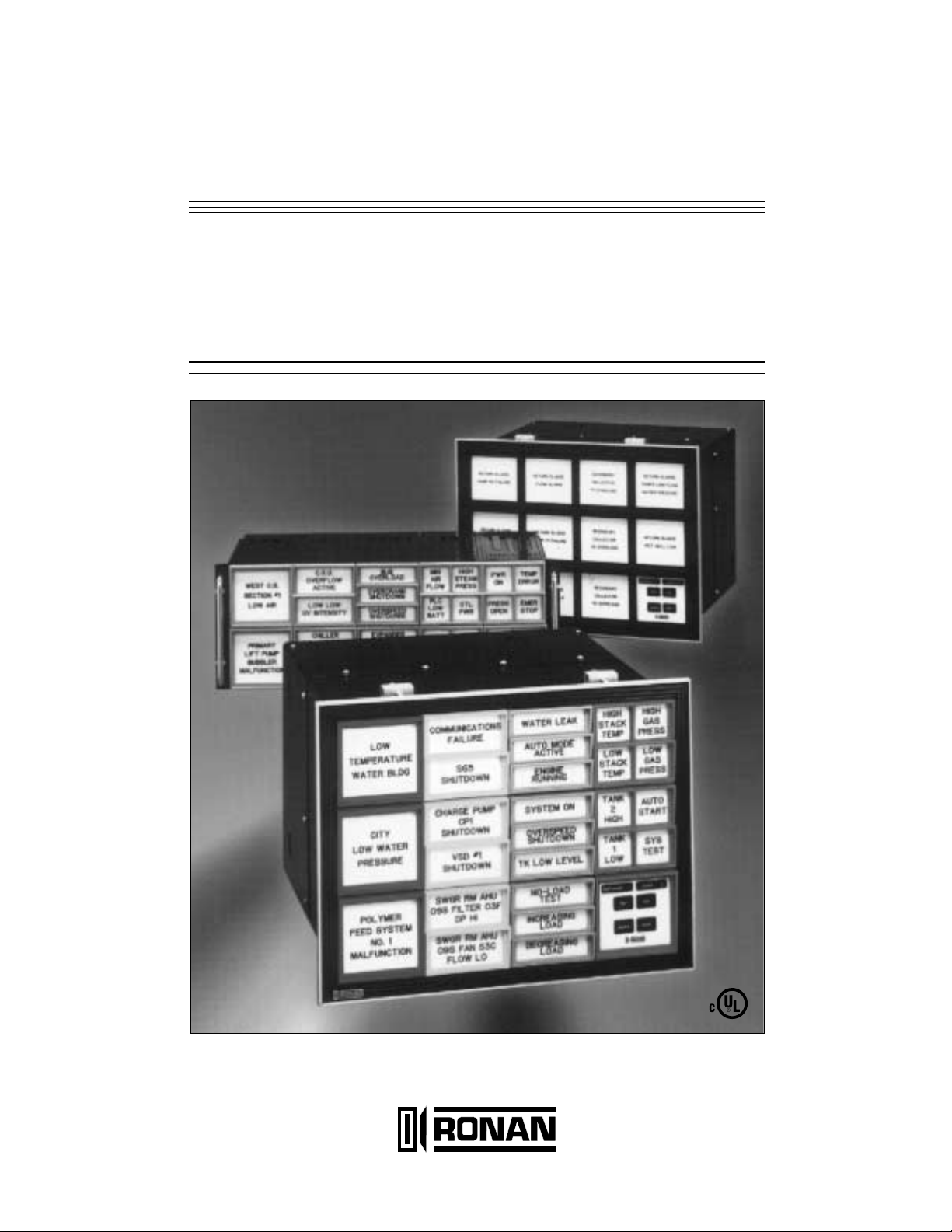
1.0 GENERAL DESCRIPTION
The Ronan Series X11SN Window Annunciator
Systems feature Monalarm, Binalarm, Trialarm and
Quadalarm displays within Ronan’s standard 3.5
inch (89 mm) by 3.5 inch (89 mm) mechanical cabinet modules. The single plug-in module construction
contains single or multipoint alarm circuitry with
maximum noise immunity and reliability. The most
popular ISA sequences, A, M, F2A, F2M, F3A, and
R are readily available. For other special
sequences, consult factory. For higher noise immunity and specific field contact time applications, a
programmable field contact time delay board is an
available option. Normally open/normally closed field
contact logic for each individual channel is jumper
switch-selectable on the single-board design. A system common trouble alarm (CTA) may be utilized for
remote group alarms. The system's CTA and reflash transistor outputs may be connected directly or
via interface relays to provide inputs to remote
annunciators.
2.0 SPECIFICATIONS
System Voltage:
Logic, Lamps: 24 Vdc ± 20%.
Field Contact Options: 24 Vdc Dry Contact, 48, 125,
250 Vdc ± 20% live input or opto-isolated 115, 240
Vac two-wire input (H and N).
Temperature Range:
Storage: -40 to 85°C (-40 to +185°F).
Operating: -40 to +60°C (-40 to +140°F).
Consult factory for extended ranges.
Power Sources:
External Power Supplies or Inverters Available for:
120 Vac ± 20%, 60 Hz; 240 Vac ± 20%, 50/60 Hz;
Converter 24, 48 or 125 Vdc ± 20%.
Power Requirements: To specify the correct power
supply, count the number of alarm modules to be
powered from the supply. Calculate the total requirements with the following equation:
Total Watts = No. of Modules x (Display Factor F + F Aux.)
F Aux.
Model F Lamps F LEDs Relay Adder
X11SN (1000 Series) 5.3 W 7.1 W 1 W
X11SN (2000 Series) 9.3 W 7.1 W 2 W
X11SN (3000 Series) 13.3 W 5.6 W 3 W
X11SN (4000 Series) 9.3 W 7.1 W 4 W
Inputs: 24 Vdc dry contact, 48, 125, 250 Vdc ±
20% live input or opto-isolated 115, 240 Vac twowire input (H and N).
Outputs:
Lamp Outputs: Fast flash, slow flash, steady on,
intermittent fast flash.
Alarm: Single audible.
Auxiliary Relay: Field selectable Form Aor B.
Contact Rating: 2A @ 28 Vdc, General Purpose or
Hermetically Sealed.
Common Trouble Alarm: Output follows FC NDE.
Reflash Option: Output on rear terminal block
point F4.
Response Time: 20 msec nominal.
Surge Withstand Capability (SWC):
All Logic Tested to: ANSI/IEEE C37.90-1989.
Controls: Integral or Remote Silence, Acknowledge, Reset, and Test: Momentary push button,
single pole, normally open.
System Size:
Multiple of Cabinet Module: 3.5 inch (89 mm) x 3.5
inch (89 mm). See dimensional information drawings for detailed dimensions.
System Weight Per Cabinet Module: 2 lbs. (909
grams) not including power supply.
3.0 EXPANSION
The Series X11SN Window Annunciator Systems
are built for expandability. This allows field expansion of the Monalarm System to either Binalarm,
Trialarm or Quadalarm, and the Binalarm to
Trialarm or Quadalarm, by simply replacing the
alarm/lamp modules and the appropriate bezels.
CAUTION: The last position of each chassis can
not be more than two alarm positions due to the
flasher, so it will only expand to Binalarm.
4.0 AUXILIARY CONTACTS
The auxiliary contact outputs may be purchased initially or added later in the field. The single, dual,
triple or quad relay circuit module plugs in from the
front of the system. The receiving multipin printed
circuit connector and the terminals for the contact
outputs are furnished with the system. Each relay
follows the selected alarm board auxiliary behavior
and provides a selectable Form A or B type contact.
The relays are available in General Purpose or
Hermetically Sealed models.
2
Page 4
5.0 MOUNTING
A. The annunciator is shipped with all of the alarm/
lamp modules, auxiliary contact module(s) and
flasher module(s) installed in the cabinet, as
specified by purchase order.
B. External horn relay(s), reflash relay, common
alarm relay, relay sockets, horns, bells, push buttons and power supply are packed separately.
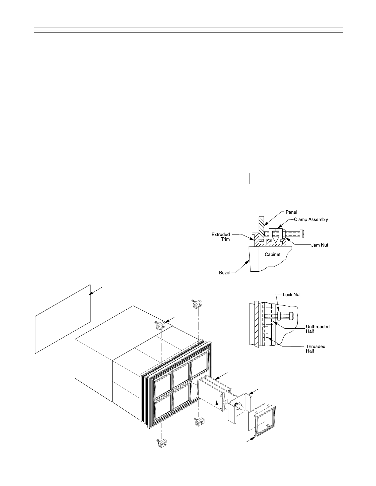
C. Install the alarm cabinet from the front of the
panel.
1. Position the cabinet in the cutout so that the
cabinet rests on the front extruded trim, see
detail A, Figure 1. Make sure that the front rim
is firmly against the panel, both top and bottom.
2. From the rear view of the panel, insert the two
halves of the clamp assembly (one half
threaded and the other half unthreaded) in the
groove of the front trim, see detail C below.
3. Slide the clamps together until both holes
align, see detail B below.
4. Insert the jack screw and tighten to secure the
cabinet in the panel. Install all the clamps the
same way and be sure to tighten evenly.
5. Tighten up the lock nuts on each jack screw.
3
Clamp
Assembly
Flasher Module
Alarm Lamp Module
Auxiliary
Contact
Module
Bezel
Rear Cover
Detail A
Detail B
Figure 1: X11SN Assembly Drawing
Detail C
D. Systems purchased with NEMA12 or NEMA4
Doors require mounting of the door before Step
C1. After removal of the mounting clamp assemblies, the system can be inserted through the
open door, sandwiching the door between the
panel and the system’s extruded trim (gasket is
furnished with door). Continue with Steps C1
through C5. Note: The panel cutout is the same
as specified in standard flush mounted alarm
systems.
E. Mount all external relays, horns and/or bells,
push buttons and power supply on the panel or
in the rear of the annunciator cabinet, where
possible.
F. Wire system’s inputs and support equipment as
shown under System’s Support Wiring.
Before turning on power read Power Up and Test
Procedure.
CAUTION
Page 5

6.0 POWER UP AND TEST PROCEDURE
It is important to review all external equipment,
including the alarm system, before turning on
power and proceeding with testing. Before
installing, verify that each component meets the
area and environment standard required by the
National Electrical Code. Particular attention must
be paid to reviewing push buttons, horn relays,
horns and bells, to see that they meet the right
classification of the electrical code.
6.1 Wiring Inspection
6.1.1 Alarm Inputs. Each active alarm input
must be wired to customer’s sensing device
that provides an opening or closing on alarm
condition. The terminals on the alarm system
for each alarm input are marked 1 and are
supplied via a pull-up resistor on each alarm
module point. This resistor is used in the V+
source to each field contact to reduce the
effect of large transients entering the alarm
chassis. Each alarm input module is provided
with a separate terminal 1. However, it is
common practice to run one common wire
from terminal 1 to many field contacts to
reduce the number of field wires required.
When using common wiring, it is important to
jumper together terminal 1 of the respective
alarm cabinet modules to provide the correct
amount of current source to the field contact.
The return wire from the field contact is wired
to terminal 2 for each respective alarm module. Since the alarm system provides the
power to the field contacts, it is important to
verify that no other voltage source appears
on either terminal 1 or terminal 2.
Note: On alarm systems where the alarm
inputs are supplied from transistor switch outputs, the V- of both systems has to be common. If the system under test has this feature, it must be verified by reviewing the electrical drawing, particularly the alarm module
schematic.
In general, the solid state alarm system is a
floating system. The V+ and V- should be
verified as ungrounded.
6.1.2 Push-button Wiring. Verify that the
push-button wires are correctly wired to all of
the push buttons, including the push-button
contacts. Refer to pages 13 through 20 for
outlined dimensions and rear terminal
4
arrangements. Insure that normally open contacts are used. For example, if the wrong contacts (normally closed) are used, this is the
same as having the operator pushing the push
button continuously, which obviously will drastically affect the operation of the alarm system.
Alarm systems using multiple alarm cabinets
may use a common set of push buttons to control the total system. A detailed check for proper installation is recommended, including diode
type isolation, if specified on the electrical
drawings.
6.1.3 Horn and Bell Wiring. Terminals H1, H2,
and CA use short circuit protected drivers to
drive associated relays and horns. The suggested minimum turn-on current of connected elements should be greater than 10
mA. The maximum horn current should not
exceed 500 mA. If electronic horns are used,
the horns can be directly connected to the
audible output terminals (H1, H2). Systems
using the conventional AC or DC horns and
bells, must use a horn relay with suitable contact rating. On multiple alarm cabinet systems
where individual power input is preferred, a
horn relay must be used with each cabinet to
maintain electrical isolation.
6.1.4 Power Supply. Verify the correct polarity
of connection to the alarm systems. In the larger system, it is important to verify the wire
sizes of the power leads to the alarm cabinets.
To protect the larger alarm chassis, it is common to provide more than one input to the cabinet in which each section is provided with a
separate filter, fuse and supply input terminals.
In systems with multiple supply input, it is necessary for the customer to make V- connections common.
6.1.5 Normally Open/Normally Closed Field
Contacts.All alarm modules are equipped for
operation with normally open or normally
closed field contacts. This is accomplished by
using a jumper switch on each alarm module,
identified as NO and NC for the normally open
and normally closed position respectively.
When the complete system is in operation, the
field contact that opens with an alarm condition
is termed a “normally closed” alarm input; conversely, the field contact that closes with an
alarm condition is termed a “normally open”
alarm input.
6.1.6 Power Up. Carefully inspect the hookup
wiring to insure conformity with the furnished
schematic. Pay particular attention to power
source polarity and verify that terminal 3 is
CAUTION
Page 6

connected common for first alert sequence
groups. Now remove the alarm modules one
at a time and determine whether or not the
normally closed/normally open switch is in the
proper position and reinsert the card firmly,
seating it in the connector. Power may now be
applied to the system.
Upon power application, the flasher module
within the system will automatically initiate a
reset cycle. The system should then be in a
quiescent state with the horn(s) off and no
lamps flashing. Some lamps may, however, be
on if their associated field contacts are in an
abnormal condition.
Depression of TEST should cause all extinguished lamps to come on flashing and the
audible alarm to sound. From this point, refer
to the particular Sequence Charts to obtain
normal system operation. When testing an installed system, be alert to the possibility that
an actual alarm may initiate during the test
procedure and appear to give conflicting
results.
7.0 TROUBLESHOOTING
7.1 General
Simple attention to the obvious can often
solve what appears to be a problem in the
system.
A.Burned out, broken, or improperly seated
bulbs will not light.
B.Alarm modules not properly seated in their
connector will prevent alarm point(s) from
functioning.
C.Alarm point pull-up resistors could be
burned providing no voltage at terminal 1.
7.2 Nonoperating Alarm System
A.Verify that the power source is operating
and that the V+ to V- voltage on the rear
terminals is in the range of 18 V to 28 V.
(Below 18 V, operation may prove erratic.)
Be sure to verify polarity.
B.If the power supply fuse blows each time
power is applied:
1. Check the Power Supply Parts List for
proper fuse size.
2. Remove Alarm System from the supply
and try again. If fuse holds, double
5
check polarity and reconnect. If fuse still
blows, remove all alarm modules and
flasher and try again. If the fuse blows at
this point, the problem has been isolated
to a short in the internal wiring.
C. If power remains on, but any or all push but-
tons (SILENCE, TEST, RESET, ACKNOWLEDGE) do not appear to function:
1. Verify proper wiring by measuring the
voltage at terminal T, A, S and/or R as
applicable. Voltage measurements are
taken with respect to the V- terminal and
should in all cases be zero volts with the
button released and V+ (20-28 Vdc) with
the button depressed.
2. If the problem persists, the Flasher
Module is suspect. Replace the Flasher
Module and try again.
3. Be alert to the possibility that a single
board can, under unique conditions,
cause what appears to be a system malfunction. The following is a typical example:
a) If a large group of F3A points comes
on fast flashing rather than intermittent flashing during TEST, one board
can be sending a signal to all of the
others. Afailure of the flasher or the
test circuit is not necessarily indicated.
b) In the above case, remove Alarm
Modules sequentially and repeat testing until the trouble clears.
c) As a general rule, common sense in
isolating the trouble will prevail. If one
or more alarm boards appear to be
malfunctioning, remove them from the
system entirely before continuing. Fill
their positions with boards from the
upper left or lower right of the system
so as to concentrate known good
modules, and then proceed with diagnostic and analysis of the remainder.
Working with several scattered
diverse problems simultaneously is
nearly always self-defeating.
d)Refer to the section on Step-by-step
Procedures for further information.
Page 7

6
7.3 Step-by-step Procedures
A. Check the system voltage and verify polar-
ity of supply input voltage and that the system voltage lines are not grounded.
B. Isolate all external devices except the input
power connections.
C. Unseat all alarm/lamp modules except the
No. 1 alarm module. At this point the only
items plugged into the alarm chassis are
one alarm module and flasher horn driver
module. Jumper the push-button input terminals on the master module to simulate
the correct connections for operations of
the alarm system (since only normally open
push-button contacts are used for all pushbutton functions, no connections will be
made for normal operation).
D. Connect a simulating set of devices to
replace the field contact as shown on the
electrical schematics on terminals 1 and 2.
E. Using the simulated field contacts and fol-
owing the test procedure instructions, check
the sequence operation of the annunciator.
F. If the first alarm module does not operate
correctly, replace the flasher module to
eliminate the possibility of a faulty flasher
module. Once established that the flasher
is functional, the fault will probably lie in
one of the following areas:
1. A faulty alarm/lamp module.
2. No +24 Vdc at terminal 1.
3. Chassis wiring fault such as a short or
cold solder joint.
G.After checking for proper operation of termi-
nal 1 output, remove the No. 1 alarm module and insert the No. 2 alarm module in
the No. 1 chassis position. If the No. 2
alarm module operates correctly, this indicates that the No. 1 alarm module is faulty.
Should the No. 2 alarm module not function in the No. 1 chassis position, the fault
lies in the chassis wiring.
H. If the failure is isolated in the chassis
wiring, remove each alarm input terminal
plate and inspect for foreign objects which
might cause a short. Review for any damaged wiring or broken connections to the
printed circuit board connector. Finally, if
the above procedure does not produce a
solution to the fault, a thorough review of all
solder joints is recommended.
I. Should No. 1 alarm function correctly, con-
tinue with the same procedure for checking
all alarm/lamps modules by seating each
module and using a simulating field contact
switch at each alarm point. After the testing,
should all the alarm/lamp modules function
correctly, it must be assumed that the entire
alarm system and modules are not faulty.
At this point, the error is now confined to the
external wiring, possible push button or
external equipment miswiring, or a short in
the field contact wiring.
J. To avoid further damage to new alarm mod-
ules, do not place another alarm module
into an alarm position that has produced circuit board trace failures. Adetailed review of
the trace failure will determine the reason
for the failure. In most cases, damage can
be the result of high voltage inputs or shorting in the chassis.
8.0 ALARM MODULES
8.1 Integral/Push-button Flasher Modules
The X11SN System can operate with either an
integral flasher or push-button flasher module.
These flasher modules function to provide slow
and fast flashing signals and filter the pushbutton signals to a V- active mode for the
alarm cards. The integral flasher is identified
by a red handle. The push-button flasher module is identified by the membrane switch and
MAINTENANCE and POWER LED indication.
The flasher module has the following specific
field selectable options:
A.Slave or master flashing module control.
B.ISA options 2 and/or 3.
C. Normally energized/deenergized common
trouble alarm output.
D. Time selectable auto-silence on Horn 1.
E.Normally open/closed contact on mainte-
nance required relay.
F. Normally open/closed contacts on alarm
point auxiliary relays (integral modules
only).
Slave (S) or Master (M) Flashing module is
controlled by slide switch SW1. In the M position, the flasher will provide slow and fast
flashing rates for all synchronized chassis.
Chassis flashing is synchronized by connecting similar rear terminals F1, F2, and V-.
Page 8

7
These terminals are located in the rear, lower
left corner of the chassis. There can only be
one master flasher in any synchronized chain.
All other system flashers must be placed in
the S position. Single system flashers must be
placed in the M position for proper alarm
sequence operation.
ISA option 2 provides an interlock to require
operation of the silence push button before
alarms can be acknowledged. This control is
located at the selectable header location
ISA2. In position 2, ISA option 2 is enabled.
Otherwise, the system can be acknowledged
at any time with ISA2 in the nonlabeled position. Push-button flasher modules that do not
have a silence push button are permanently
configured in the nonlabeled position.
ISA option 3 provides an interlock to require
operation of the acknowledge push button
before alarms can be reset by the reset push
button. This interlock control is located at the
selectable header location ISA3. In position 3,
ISA option 3 is enabled. The nonlabeled position will allow system reset at anytime.
Common Trouble Alarm operation is determined by the group alarm bus/CTA. This bus
feeds the flasher as an input and is available
to the user as an active low output at rear terminal CA. This terminal is located in the rear,
lower left corner of the chassis. This output
can be controlled as normally energized/deenergized at header location CTA.
In the NO position, the CA output will follow
the alarm card CTA designation. For example,
an alarm that follows the the field contacts
NDE (normally deenergized) will provide an
active V- output at CAwhen any field contact
is abnormal and the flasher CTA selection is
NO. The user could configure this particular
system as normally energized CA following
field contacts by putting the CTA switch in the
NC position.
Users who elect to have the automatic horn
silence option on Horn 1 configure the horn
time at header locations TADJ (time adjustment) and TRNG (time range). The available
horn time ranges are 1 and 10 minutes.
These ranges are selected at the TRNG
header in the respective 1 and 10 positions.
Half-time and full time is selected at header
location TADJ in the respective L (low) and
H(high) positions. For example; 30 second
Horn 1 auto-silence is selected by placing
TRNG in position 1 and TADJ in position L.
The other available configurations are shown
in the table below.
Horn 1
TRNG TADJ Auto Silence
1 L 30 sec.
1 H 1 min.
10 L 5 min.
10 H 10 min.
All flashers have a maintenance required
relay that energizes on flasher failure or when
24 volts is applied at terminal block F3 in the
rear, lower left corner of the chassis. Flasher
failure occurs when either the fast or slow
flash signals are not available to the alarm
card bus. The relay contact is available to the
user on terminals F5 and F6. The Normally
open or closed status can be selected on the
flasher card at the header selector switch
MAIN as NO and NC respectively. Push-button flashers have an additional red MAINTENANCE front panel LED that can additionally
follow the CTA or AL2 bus. This LED behavior
is permanently selected during initial ordering. The green POWER LED indicates when
24 volts is applied to system power.
Systems that occupy the flasher cabinet with
alarm points can specify up to two auxiliary
relays on the integral flasher card. Header
selector switches (RLYA, RLYB) are also on
the flasher card to determine the normally
open or closed status.
8.2 Alarm Sequence/Display Module
The module X11SN is offered in two separate
sequences as described in ANSI/ISAS18.11979 (R1985). On PCB X11-1013C and X111020, the operating sequence is selected as
labeled at respective headers SEQA-SEQD.
On the programmable version (PCB X111019B), the sequence selection is made at
slide switch SEQ. Switches 1-4 are connected for field contacts FCA-FCD respectively.
J5 and J6 of PCB X11-1019B are used when
the field contact selectable time delay board
is ordered. The time delay selects 1 of 32 different time responses using switch TIME.
Each field contact can bypass this selection
using switch BYPASS. BYPASS switch positions 1-4 correspond to field contacts FCAFCD respectively and will have the nominal
20 ms. response when selected. Otherwise,
Page 9

Bypass Switch Selection
Channel A(1) and Channel C(3) in ON position bypasses the time selected by TIME. The FC response
for Channel Aand Channel C will be 20 ms. nominal.
Channel B(2) and Channel D(4) in off position selects
the field contact response selected by TIME, in this
case, 3.0 seconds.
Time Switch Selection
The table below shows that with switches 2 and 3 in
the ON position and 1, 4, and 5 in the OFF position,
3.0 seconds is selected for field contact response.
Detail A: Time Board Operation Example.
the field contact response will be the time
selected by switch TIME. See Figure 2, Detail
A for a time board operation example.
Dual horn selection is offered as an option to
choose the active horn bus HORN1 and
HORN2. This option should be used when the
user needs to separate module groups by
activating different horns. On PCBs X111013C and X11-1020, the horn selection is
made at headers HORNA-HORND. These
refer to associated field contacts FCA-FCD.
The programmable version uses a slide switch
labeled HORN. The OFF position selects
HORN1 and the ON position selects HORN2.
Switches 1-4 are connected for field contacts
FCA-FCD respectively.
Although ordering auxiliary relay boards is not
mandatory, the X11SN system is designed so
that auxiliary relay behavior must be selected.
The basic options available choose between
Normally Energized/Deenergized following the
field contact or alarm cycle behavior. The specific options available can be consulted in the
X11SN sales brochure. When selectable auxiliary behavior is chosen, an on board selector
switch is located at SW1 on PCBs X11-1013C
and X11-1020. PCB X11-1019B uses selector
switch AUX. See specific sequence charts for
specific auxiliary relay behavior. NOTE:
Unless otherwise specified, the standard auxiliary relay option is normally non-energized follow field contact.
PCB X11-1019B (programmable) has an additional header J7 and slideswitch GEN. The
header J7 is used for parallel port programming of the device located at U6. This header
should remain unconnected and without any
additional connected shunts during normal circuit operation. The slideswitch GEN is provided when unusual or non-standard circuit performance or configuration is necessary.
Normally, most assemblies do not populate
slideswitch GEN. See Figure 3 (see page 9),
Details B and C for header and switch locations of PCB X11-1019B.
The combination display/alarm module contains a single, dual, triple, or quad alarm channel circuit with the appropriate lamp display
constructed as a single plug-in module. The
modules are removable from the front of the
system without the interference to the remaining channels of the
8
Figure 2: X11-1024 PCB Switch Locations.
Switch Time Time Switch Time Time
12345 Delay 12345 Delay
00000 50 msec. 00001 45 sec.
10000 100 msec. 10001 1 min.
01000 300 msec. 01001 90 sec.
11000 0.5 sec. 11001 2 min.
00100 1.0 sec. 00101 3 min.
10100 2.0 sec. 10101 4 min.
01100 3.0 sec. 01101 5 min.
11100 4.0 sec. 11101 6 min.
00010 5.0 sec. 00011 7 min.
10010 6.0 sec. 10011 8 min.
01010 7.0 sec. 01011 9 min.
11010 8.0 sec. 11011 10 min.
00110 9.0 sec. 00111 15 min.
10110 10.0 sec. 10111 30 min.
01110 15.0 sec. 01111 45 min.
1111 0 30.0 sec. 11111 60 min.
Page 10

system. The window display areas are contained within Ronan’s standard coloredbezels, allowing multiline engraving on single or sandwich lenses. The alarm logic may
interface with a normally open or normally
closed field contact. The field contacts are
interrogated by the system’s 24 Vdc logic
supply, or optionally, with 125 Vdc from a
dual output power supply, if so specified. In
addition, the module’s input circuit is
designed to accept a logic voltage without
external components.
9
C30
C29
R46
R30
R31
C21
J4
J5
C2
R6
Z1
R7Z2
C5
R4
D1
C3
R8
C6
R9
R10
COMPONENT SIDE
C9
C10
NO
NO
NO
NO
FCA
NC
FCB
NC
FCC
NC
FCD
NC
C16
R29
R69
R66
R56
R64
C24
C20
C15
C7
R14
R26
J3
B
A
J1
R43
R24
R12
R12
C1
R2
Z3
Z4
Z7
Z8
J2
Z16
Z15
Z14
Z13
Z12
Z11
Z10
Z9
U6
R80
R81
VR1
J7
R76
U11
J6
Q8
Q6
Q5
Q4
Q3
Q2
Q1
C23
D3
D4
D5
D6
D7
D8
D9
D10
D2
R20
R19
C11
Q7
U7
C44
C45
R84
U12
U8
Q9
GEN
AUX
HORN
SEQ
C33
C32
C34
C35
D14
R73
R74
R75
U10
C28
R62
R51
R52
R34
R35
R36
C17
R37
R38
Z5
Z6
R53
R54
R21
R39
C13
C18
C14
C19
R22
R40
R23
R55
PBA
PBB
PBC
PBD
C12
C4
R18
R63
R83
R82
R77
L5
L7
L6
L4
L3
L1
L2
L8
D13
D12
D11
U9
U13
U14
C31
R79
R78
R72
U4
C22
R61
R58
C26
R15
R11
R1
R27
R16
R28
R44
R67
R68
R57
R25
R13
R41
R42
R65
R45
U5
U1
C8
C25
R60
R59
R71
R70
C36
C37
C38
C39
C40
C41
C42
C43
C27
R49
R32
R48
R47
R50
R33
R3
R17
R5
U2
U3
Figure 3: X11-1019B PCB Switch Locations.
SEQ Switch Selection
Channel A(1) and Channel B(2) in ON position
selects M Sequence. Channel C(3) and Channel
D(4) in OFF position selects ASequence.
Horn Switch Selection (Optional)
Channel A(1) and Channel C(3) in OFF position
selects Horn1. Channel B(2) and Channel D(4) in
ON position selects Horn2.
FCA
NC
NO
NO
NO
NO
FCB
NC
FCC
NC
FCD
NC
Field Contact Switch Selection
FCA and FCB set in the positions shown select
Normally Open Field Contacts. FCC and FCD set in
the positions shown, select Normally Closed Field
Contacts.
Detail C: Field Contact Switch Selection Example.
Detail B: Example X11SN4MA0122* Card Switch Selection.
Sequence “M” Manual Reset or “A” Automatic Reset.
* See X11SN Window Annunciator Systems sales brochure for
* alarm card assembly numbers.
ON
1
SEQ
2
GEN
3
4
AUX
HORN
ON
1
2
3
4
Page 11

9.2 M, Manual Reset
1. Acknowledge, reset and test push
buttons.
2. Alarm audible device.
3. Lock-in momentary alarms until
acknowledged.
4. The audible device is silenced and
flashing stops when acknowledged.
5. Manual reset of acknowledged alarm
indications after process conditions
return to normal.
6. Operational test.
8.3 Output Features
The X11SN System provides the following features on the terminal located in the lower, left,
rear terminal plate.
8.3.1 Common Trouble Alarm. This output is
at terminal CA and follows the field contacts A
24 Vdc relay wired between CA and V+ will
energize whenever a point is abnormal (in
alarm) and the relay will stay energized until
all points in the system return to normal.
8.3.2 Reflash. This output is at terminal F4
and follows the field contacts. A 24 Vdc relay
wired between F4 and V+ will energize whenever a point is abnormal (in alarm). If a second point goes abnormal (in alarm) while the
first point is still abnormal, the reflash module
briefly returns to normal then goes abnormal
until all points return to normal.
8.3.3 Auxiliary Contact Module. The auxiliary
contact module is available with a single, dual,
triple or quad relay circuit, accommodating the
window density selected. The modules plug in
from the front of the system and may be purchased initially or added later in the field. The
terminals for the contact outputs are furnished as
part of the system. Each relay provides a selectable Form A or B type contact with a rating of 2
A at 28 Vdc. Relays are available in either
Hermetically Sealed or General Purpose types.
Normally open (Type A) or normally closed (Type
B) contact is available for each alarm point at
their respective rear terminal block terminals 5
and 6. The normal operation (NO/ NC) can be
changed on the auxiliary contact module at headers marked AUX1, AUX2, AUX3, or AUX4.
8.3.4 Transistor Output
Terminal 4 (TO) of each alarm I/O terminal strip
provides an open collector output (pulling to -V)
programmable for various system functions. A
typical application is to drive an auxiliary relay
following the field contact or lamp logic.
10
9.0 STANDARD SEQUENCES (For other special sequences consult factory)
9.1 A, Automatic Reset
1. Acknowledge and test push buttons.
2. Alarm audible device.
3. Lock-in of momentary alarms until
acknowledged.
4. The audible device is silenced and
flashing stops when acknowledged.
5. Automatic reset of acknowledged
alarm indications when process
conditions return to normal.
6. Operational test.
Page 12

PROCESS
PROCESS
PROCESS
PROCESS
PROCESS
ABNORMAL OR
NORMAL
NORMAL
ABNORMAL
ABNORMAL OR
NORMAL
ABNORMAL OR
NORMAL
FIRST OUT
RESET
FIRST ABNORMAL
RETURN TO
NORMAL
FIRST OUT RESET
WHILE NORMAL
SUB ALARM
NORMAL
SUB
ACKNOWLEDGED
FIRST OUT RESET
WHILE ABNORMAL
FIRST
ACKNOWLEDGED
SLOW
FLASHING
FIRST ALARM
ACKNOWLEDGE
WHILE NORMAL
SUBSEQUENT
ABNORMAL
ACKNOWLEDGE
WHILE
ABNORMAL
FAST FLASH
OFF
ON
INTERMITTENT
FLASHING
SEQUENCE
SEQUENCE
SEQUENCE
SEQUENCE
SEQUENCE
VISUAL
VISUAL
VISUAL
VISUAL
VISUAL
AUDIBLE
AUDIBLE
AUDIBLE
AUDIBLE
AUDIBLE
AUDIBLE
SILENT
SILENT
SILENT
ACKNOWLEDGE
AUDIBLE
SEQUENCE DIAGRAM
9.3 F3A, Automatic Reset First
Out with First Out Flashing
and Reset Push Button
1. Acknowledge, first-out reset
and test push buttons.
2. Alarm audible device.
3. Lock-in of momentary alarms
until acknowledged.
4. First-out flashing different from
subsequent flashing.
5. First-out reset push button to
change the first out visual
indication to be the same as
subsequent visual indications.
6. Automatic reset of acknowledge alarm indications when
process conditions return to
normal.
7. Operational test.
9.4 R, Ringback (Ronan ID RD)
1. Acknowledge, reset, and test
push buttons.
2. Alarm and ringback audible
devices.
3. Lock-in of momentary alarms
until acknowledged.
4. The audible device is silenced
and fast flashing stops when
acknowledged.
5. Ringback visual and audible
indications when process
conditions return to normal.
6. Manual reset of ringback
indications.
7. Operational test.
11
9.0 SEQUENCES (CONT.)
PROCESS
PROCESS
PROCESS
PROCESS
ABNORMAL
NORMAL
NORMAL
ABNORMAL OR
NORMAL
RESET
TO ABNORMAL
RETURN
TO NORMAL
RETURN TO ABNORMAL
ACKNOWLEDGE
WHILE ABNORMAL
ACKNOWLEDGE
WHILE NORMAL
ACKNOWLEDGED
RINGBACK
NORMAL
ALARM
ON
SLOW FLASHING
OFF
FAST FLASHING
RINGBACK
AUDIBLE
RINGBACK
AUDIBLE
RINGBACK
AUDIBLE
RINGBACK
AUDIBLE
ALARM
AUDIBLE
ALARM
AUDIBLE
ALARM
AUDIBLE
ALARM
AUDIBLE
SEQUENCE
SEQUENCE
SEQUENCE
SEQUENCE
VISUAL
VISUAL
VISUAL
VISUAL
SILENT
SILENT
SILENT
AUDIBLE
SILENT
AUDIBLE
SILENT
SILENT
SEQUENCE DIAGRAM
Page 13

PROCESS
PROCESS
PROCESS PROCESS
NORMAL
ABNORMAL OR
NORMAL
ABNORMAL OR
NORMAL
ABNORMAL OR
NORMAL
SUBSEQUENT TO
ABNORMAL
ACKNOWLEDGE
WHILE NORMAL
SUBSEQUENT
ALARM
ACKNOWLEDGE WHILE ABNORMAL
NORMAL
ACKNOWLEDGED
FIRST ALARM
ACKNOWLEDGE
(FIRST OUT RESET)
FIRST TO
ABNORMAL
RETURN TO
NORMAL
ON
OFF
ON
SLOW FLASHING
SEQUENCE
SEQUENCE
SEQUENCE SEQUENCE
VISUAL
VISUAL
VISUAL VISUAL
AUDIBLE
AUDIBLE
AUDIBLE AUDIBLE
AUDIBLE
SILENT
SILENT AUDIBLE
SEQUENCE DIAGRAM
9.5 F2A, Automatic Reset First Out
with No Subsequent Alarm
Flashing
(Ronan ID FS)
1. Acknowledge, reset, and test push
buttons.
2. Alarm audible device.
3. Lock-in of momentary alarms until
acknowledged.
4. Flashing indication for first alarm only.
New subsequent alarms have the
same visual indication as acknowledged alarms.
5. First out indication is reset when
acknowledged.
6. Automatic reset of acknowledged
alarm indications when process
conditions return to normal.
7. Operational test.
9.6 F2M, Manual Reset First Out with
No Subsequent Alarm Flashing
(Ronan ID FSM)
1. Acknowledge, reset, and test push
buttons.
2. Alarm audible device.
3. Lock-in of momentary alarms until
acknowledged.
4. Flashing indication for first alarm only.
New subsequent alarms have the
same visual indication as acknowledged alarms.
5. First out indication is reset when
acknowledged.
6. Manual reset of acknowledged alarm
indications after process conditions
return to normal.
7. Operational test.
12
9.0 SEQUENCES (CONT.)
PROCESS
PROCESS
PROCESS PROCESS
NORMAL
ABNORMAL OR
NORMAL
ABNORMAL OR
NORMAL
ABNORMAL OR
NORMAL
SUBSEQUENT TO
ABNORMAL
SUBSEQUENT
ALARM
ACKNOWLEDGE
NORMAL
ACKNOWLEDGED
FIRST ALARM
ACKNOWLEDGE
(FIRST OUT RESET)
FIRST TO
ABNORMAL
RESET WHILE
NORMAL
ON
OFF
ON
SLOW FLASHING
SEQUENCE
SEQUENCE
SEQUENCE SEQUENCE
VISUAL
VISUAL
VISUAL VISUAL
AUDIBLE
AUDIBLE
AUDIBLE AUDIBLE
AUDIBLE
SILENT
SILENT AUDIBLE
SEQUENCE DIAGRAM
Page 14

10.1Monalarm Dimensional Drawings
13
A Overall
A Overall
B Cutout
B Cutout
2.75” (69.85 mm) High x
3.00” (76.20 mm) Wide
Alarm Window
Optional Push-button
Flasher Module or
Front Accessible
Flasher Module
14.12” (358.78 mm)
0.56” (14.22 mm)
2.00”
(50.80 mm)
Removable
Rear Cover
with Captive
Fasteners
A
0.75” (19.05 mm)
Conduit Knock-out
Flush-mount - Front View
X11SN-1000 & X11SNLR-1000
Relay Rack-mount - Front and Side View X11SNRR-1000
Flush-mount - Side View
X11SN-1000
Flush-mount - Side View
X11SNLR-1000
11.75” (298.45 mm)
0.56” (14.22 mm)
Max. Panel Thickness
Field Wiring
Terminal
Rear Cover
Removed
Fuse
A
Less Rear
Detail A
19.00” (482.60 mm) Overall
A
Overall
17.75” (450.85 mm) Rack Opening
2.75” (69.85 mm) High x 3.00” (76.20 mm) Wide Alarm Window
11.75” (298.45 mm)
Fuse
Field
Contact
Terminals
No. of Windows A Overall B Cutout
High or Wide Inches mm Inches mm
1 5.00 127.00 4.38 111.25
2 8.50 215.90 7.88 200.15
3 12.00 304.80 11.38 289.05
4 15.50 393.70 14.88 377.95
5 19.00 482.60 18.38 466.85
6 22.50 571.50 21.88 555.75
7 26.00 660.40 25.38 644.65
8 29.50 749.30 28.88 733.55
9 33.00 838.20 32.50 825.50
10 36.50 927.10 36.00 914.40
11 40.00 1016.00 39.50 1003.30
12 43.50 1104.90 43.00 1092.20
Number of Number of A Overall
Windows High Windows Wide Inches mm
1* 5** 3.50 88.90
2* 5** 7.00 177.80
3* 5** 10.50 266.70
4* 5** 14.00 355.60
**Not limited to 2 high.
**Limited to 5 wide only. 19.00” (482.60) mm rack.
Also available 6 wide. 24.00” (609.60 mm) rack.
A
A
Page 15

10.2Dualarm Dimensional Drawings
19.00” (482.60 mm) Overall
A
Overall
17.75” (450.85 mm) Rack Opening
1.44” (35.56 mm) High x 3.00” (76.20 mm) Wide Alarm Window
Flush-mount - Front View
X11SN-2000 & X11SNLR-2000
Relay Rack-mount - Front and Side View X11SNRR-2000
Flush-mount - Side View
X11SN-2000
Flush-mount - Side View
X11SNLR-2000
11.75” (298.45 mm)
0.56” (14.22 mm)
Max. Panel Thickness
Field Wiring
Terminal
Rear Cover
Removed
Fuse
A
Less Rear
Detail A
11.75” (298.45 mm)
Fuse
Field
Contact
Terminals
No. of Windows A Overall B Cutout
High Wide Inches mm Inches mm
2 6 5.00 127.00 4.38 111.25
4 2 8.50 215.90 7.88 200.15
6 3 12.00 304.80 11.38 289.05
8 4 15.50 393.70 14.88 377.95
10 5 19.00 482.60 18.38 466.85
12 6 22.50 571.50 21.88 555.75
14 7 26.00 660.40 25.38 644.65
16 8 29.50 749.30 28.88 733.55
18 9 33.00 838.20 32.50 825.50
20 10 36.50 927.10 36.00 914.40
22 11 40.00 1016.00 39.50 1003.30
24 12 43.50 1104.90 43.00 1092.20
Number of Number of A Overall
Windows High Windows Wide Inches mm
1* 5** 3.50 88.90
2* 5** 7.00 177.80
3* 5** 10.50 266.70
4* 5** 14.00 355.60
**Not limited to 2 high.
**Limited to 5 wide only. 19.00” (482.60) mm rack.
Also available 6 wide. 24.00” (609.60 mm) rack.
A Overall
A Overall
B Cutout
B Cutout
1.44” (69.85 mm) High x
3.00” (76.20 mm) Wide
Alarm Window
Optional Push-button
Flasher Module or
Front Accessible
Flasher Module
14
A
B
A
B
14.12” (358.78 mm)
0.56” (14.22 mm)
Max. Panel Thickness
A
2.00”
(50.80 mm)
Removable
Rear Cover
with Captive
Fasteners
0.75” (19.05 mm)
Conduit Knock-out
Page 16

10.3 Trilarm Dimensional Drawings
15
A Overall
A Overall
B Cutout
B Cutout
.86” (69.85 mm) High x
3.00” (76.20 mm) Wide
Alarm Window
Optional Push-button
Flasher Module or
Front Accessible
Flasher Module
14.12” (358.78 mm)
0.56” (14.22 mm)
2.00”
(50.80 mm)
Removable
Rear Cover
with Captive
Fasteners
A
0.75” (19.05 mm)
Conduit Knock-out
Flush-mount - Front View
X11SN-3000 & X11SNLR-3000
Relay Rack-mount - Front and Side View X11SNRR-3000
Flush-mount - Side View
X11SN-3000
Flush-mount - Side View
X11SNLR-3000
11.75” (298.45 mm)
0.56” (14.22 mm)
Max. Panel Thickness
Field Wiring
Terminal
Rear Cover
Removed
Fuse
A
Less Rear
Detail A
19.00” (482.60 mm) Overall
A
Overall
17.75” (450.85 mm) Rack Opening
.86” (21.84 mm) High x 3.00” (76.20 mm) Wide Alarm Window
11.75” (298.45 mm)
Fuse
Field
Contact
Terminals
No. of Windows A Overall B Cutout
High Wide Inches mm Inches mm
3 1 5.00 127.00 4.38 111.25
6 2 8.50 215.90 7.88 200.15
9 3 12.00 304.80 11.38 289.05
12 4 15.50 393.70 14.88 377.95
15 5 19.00 482.60 18.38 466.85
18 6 22.50 571.50 21.88 555.75
21 7 26.00 660.40 25.38 644.65
24 8 29.50 749.30 28.88 733.55
27 9 33.00 838.20 32.50 825.50
30 10 36.50 927.10 36.00 914.40
33 11 40.00 1016.00 39.50 1003.30
36 12 43.50 1104.90 43.00 1092.20
Number of Number of A Overall
Windows High Windows Wide Inches mm
1* 5** 3.50 88.90
2* 5** 7.00 177.80
3* 5** 10.50 266.70
4* 5** 14.00 355.60
**Not limited to 2 high.
**Limited to 5 wide only. 19.00” (482.60) mm rack.
Also available 6 wide. 24.00” (609.60 mm) rack.
A
B
C
A
B
C
Page 17

10.4 Quadalarm Dimensional Drawings
16
A Overall
A Overall
B Cutout
B Cutout
1.44” (35.56 mm) High x
1.44” (35.56 mm) Wide
Alarm Window
Optional Push-button
Flasher Module or
Front Accessible
Flasher Module
14.12” (358.78 mm)
0.56” (14.22 mm)
2.00”
(50.80 mm)
Removable
Rear Cover
with Captive
Fasteners
A
0.75” (19.05 mm)
Conduit Knock-out
Flush-mount - Front View
X11SN-4000 & X11SNLR-4000
Relay Rack-mount - Front and Side View X11SNRR-4000
Flush-mount - Side View
X11SN-4000
Flush-mount - Side View
X11SNLR-4000
11.75” (298.45 mm)
0.56” (14.22 mm)
Max. Panel Thickness
Field Wiring
Terminal
Rear Cover
Removed
Fuse
A
Less Rear
Detail A
19.00” (482.60 mm) Overall
A
Overall
17.75” (450.85 mm) Rack Opening
1.44” (35.56 mm) High x 1.44” (35.56 mm) Wide Alarm Window
11.75” (298.45 mm)
Fuse
Field
Contact
Terminals
No. of Windows A Overall B Cutout
High or Wide Inches mm Inches mm
2 5.00 127.00 4.38 111.25
4 8.50 215.90 7.88 200.15
6 12.00 304.80 11.38 289.05
8 15.50 393.70 14.88 377.95
10 19.00 482.60 18.38 466.85
12 22.50 571.50 21.88 555.75
14 26.00 660.40 25.38 644.65
16 29.50 749.30 28.88 733.55
18 33.00 838.20 32.50 825.50
20 36.50 927.10 36.00 914.40
22 40.00 1016.00 39.50 1003.30
24 43.50 1104.90 43.00 1092.20
Number of Number of A Overall
Windows High Windows Wide Inches mm
1* 5** 3.50 88.90
2* 5** 7.00 177.80
3* 5** 10.50 266.70
4* 5** 14.00 355.60
**Not limited to 2 high.
**Limited to 5 wide only. 19.00” (482.60) mm rack.
Also available 6 wide. 24.00” (609.60 mm) rack.
A
B
C
D
A
B
C
D
Page 18

17
10.5 Standard Rear Terminal Arrangements and Wiring - 24 Vdc
Monalarm X11SN-1000
Binalarm X11SN-2000
Trialarm X11SN-3000
Quadalarm X11SN-4000
AB
ABAB
1
2
3
G
CA
V-V
+
V
+
V
+
24 Vdc Input
Electronic
Horn
AC Horn
Horn 1 Relay
Ack
Silence
Test
Reset
Horn 2 Relay
7
7
72
3
1
31
2
2
K1
K2
K1 or K2
Common
Trouble
K3
K3
V
+
V-
DETAIL A
DETAIL B
DETAIL C
FUSE
Typical Field Contact Wiring
For All Alarm Positions
*
*
*
*
T
S
A
R
H1
H2
AB
AB
C
C
AB
1
2
3
G
CA
V-V
+
V
+
V
+
24 Vdc Input
Electronic
Horn
AC Horn
Horn 1 Relay
Ack
Silence
Test
Reset
Horn 2 Relay
7
7
72
3
1
31
2
2
K1
K2
K1 or K2
Common
Trouble
K3
K3
V
+
V-
DETAIL A
DETAIL B
DETAIL C
FUSE
Typical Field Contact Wiring
For All Alarm Positions
*
*
*
*
T
S
A
R
H1
H2
AB
AB
C
C
D
ADB
1
2
3
G
CA
V-V
+
V
+
V
+
24 Vdc Input
Electronic
Horn
AC Horn
Horn 1 Relay
Ack
Silence
Test
Reset
Horn 2Relay
7
7
72
3
1
31
2
2
K1
K2
K1 or K2
Common
Trouble
K3
K3
V
+
V-
DETAIL A
DETAIL B
DETAIL C
FUSE
Typical Field Contact Wiring
For All Alarm Positions
*
*
*
*
T
S
A
R
H1
H2
Detail A
1. (F1, F2) flasher sync. connect for
multi chassis applications.
2. (F3) apply +24 Vdc to activate
maintenance required LED and
relay.
3. (F5/F6) maintenance required relay
contact output.
4. In last position (3) of Trialarm and
Quadalarm units, the flasher occupies positions “C” and “D”, therefore, only positions “A” and “B” are
available.
Notes:
Detail B
5. (ME) Used to form first alert groups.
6. Auxiliary output NO/NC selectable.
7. (TO) Transistor Output.
Detail C
8. (CA) common trouble alarm transistor driver output.
Flasher Sync
for Multichassis
Applications
Reflash Output or
Lamp Inhibit +24Vdc
Maintenance
Required Dry Contact
F1
F2
24 Vdc Input
to Activate
F3
Maintenance
F4
Required Relay
and LED
F5
F6
V+
CA
V+
To Push-button
Wiring
Common
Trouble
2
7
K3
3
1
K3
Page 19

18
10.6 Rear Terminal Arrangements and Wiring for 125 Vdc Field Contact
Monalarm X11SN-1000
Binalarm X11SN-2000
Trialarm X11SN-3000
Quadalarm X11SN-4000
A
A
B
B
A
B
1
2
3
G
CA
V-V
+
V
+
V
+
24 Vdc
Input
125 Vdc
Field
Contact
Input
Electronic
Horn
AC Horn
Horn 1 Relay
Ack
Silence
Test
Reset
Horn 2 Relay
7
7
72
3
1
31
2
2
K1
K2
K1 or K2
+
Common
Trouble
K3
K3
V
+
V-
-
DETAIL A
DETAIL B
DETAIL C
FUSE
Typical Field Contact Wiring
For All Alarm Positions
*
*
*
*
T
S
A
R
H1
H2
A
A
B
C
C
B
A
B
1
2
3
G
CA
V-V
+
V
+
V
+
24 Vdc
Input
125 Vdc
Field
Contact
Input
Electronic
Horn
AC Horn
Horn 1 Relay
Ack
Silence
Test
Reset
Horn 2 Relay
7
7
72
3
1
31
2
2
K1
K2
K1 or K2
+
Common
Trouble
K3
K3
V
+
V-
-
DETAIL A
DETAIL B
DETAIL C
FUSE
Typical Field Contact Wiring
For All Alarm Positions
*
*
*
*
T
S
A
R
H1
H2
A
A
B
C
CD
D
B
A
B
1
2
3
G
CA
V-V
+
V
+
V
+
24 Vdc
Input
125 Vdc
Field
Contact
Input
Electronic
Horn
AC Horn
Horn 1 Relay
Ack
Silence
Test
Reset
Horn 2 Relay
7
7
72
3
1
31
2
2
K1
K2
K1 or K2
+
Common
Trouble
K3
K3
V
+
V-
-
DETAIL A
DETAIL B
DETAIL C
FUSE
Typical Field Contact Wiring
For All Alarm Positions
*
*
*
*
T
S
A
R
H1
H2
Detail A
1. (F1, F2) flasher sync. connect for
multi chassis applications.
2. (F3) apply +24 Vdc to activate
maintenance required LED and
relay.
3. (F5/F6) maintenance required relay
contact output.
4. In last position (3) of Trialarm and
Quadalarm units, the flasher occupies positions “C” and “D”, therefore, only positions “A” and “B” are
available.
Notes:
Detail B
5. (ME) Used to form first alert groups.
6. Auxiliary output NO/NC selectable.
7. (TO) Transistor Output.
Detail C
8. (CA) common trouble alarm transis-
tor driver output.
Flasher Sync
for Multichassis
Applications
Reflash Output or
Lamp Inhibit +24Vdc
Maintenance
Required Dry Contact
F1
F2
24 Vdc Input
to Activate
F3
Maintenance
F4
Required Relay
and LED
F5
F6
V+
CA
V+
To Push-button
Wiring
Common
Trouble
2
7
K3
3
1
K3
Page 20

10.7 Rear Terminal Arrangements and Wiring for Transistor Input
Binalarm X11SN-2000
Trialarm X11SN-3000
Quadalarm X11SN-4000
Detail A
1. (F1, F2) flasher sync. connect for
multi chassis applications.
2. (F3) apply +24 Vdc to activate
maintenance required LED and
relay.
3. (F5/F6) maintenance required relay
contact output.
4. In last position (3) of Trialarm and
Quadalarm units, the flasher occupies positions “C” and “D”, therefore, only positions “A” and “B” are
available.
Notes:
Detail B
5. (ME) Used to form first alert groups.
6. Auxiliary output NO/NC selectable.
7. (TO) Transistor Output.
Detail C
8. (CA) common trouble alarm transistor driver output.
19
DETAIL A
2
2
K1
K2
T
S
A
R
7
H1
H2
7
31
Common
Trouble
CA
Test
Silence
Ack
Reset
Horn 1 Relay
Horn 2 Relay
AC Horn
Electronic
Horn
K1 or K2
+
V
72
K3
3
1
K3
+
V
DETAIL C
DETAIL B,Typical for
All Alarm Positions
G
+
V-V
3
24 Vdc Input
FUSE
V-
+
V
Flasher Sync
for Multichassis
Applications
Reflash Output or
Lamp Inhibit +24Vdc
Maintenance
Required Dry Contact
F1
F2
24 Vdc Input
to Activate
F3
Maintenance
F4
Required Relay
and LED
F5
F6
BA
2
1
DETAIL A
2
2
K1
K2
T
S
A
R
7
H1
H2
7
31
Common
Trouble
CA
72
1
V+V
K3
K3
+
3
Test
Silence
Ack
Reset
Horn 1 Relay
Horn 2 Relay
AC Horn
Electronic
Horn
K1 or K2
DETAIL A
2
2
K1
K2
T
S
A
R
7
H1
H2
7
31
Common
Trouble
CA
72
1
K3
+
+
V
V
K3
3
Test
Silence
Ack
Reset
Horn 1 Relay
Horn 2 Relay
AC Horn
Electronic
Horn
K1 or K2
DETAIL B,Typical for
3
DETAIL C
24 Vdc Input
DETAIL B,Typical for
3
DETAIL C
24 Vdc Input
All Alarm Positions
G
+
V-V
FUSE
2
V-
+
V
All Alarm Positions
G
+
V-V
FUSE
2
V-
+
V
CB A
1
DCBA
1
V+
CA
V+
To Push-button
Wiring
Common
Trouble
2
7
K3
3
1
K3
Page 21

20
10.8 Rear Terminal Arrangements and Wiring for Opto-coupled Input
115 Vac, 24 Vdc, 48 Vdc, 125 Vdc
Monalarm X11SN-1000
Binalarm X11SN-2000
Trialarm X11SN-3000
Quadalarm X11SN-4000
AB
A
AB
B
1
2
3
G
CA
V-V
+
V
+
V
+
24 Vdc Input
Electronic
Horn
AC Horn
Horn 1 Relay
Ack
Silence
Test
Reset
Horn 2 Relay
7
7
72
3
1
31
2
2
K1
K2
K1 or K2
Common
Trouble
K3
K3
V
+
V-
DETAIL A
DETAIL C
DETAIL B
FUSE
Typical Field Contact
NO or NC
+++
+
++
*
*
*
*
Input Voltage
T
S
A
R
H1
H2
ABC
A
ABB
C
T
S
A
R
H1
1
2
3
H2
G
CA
V-V
+
V
+
V
+
24 Vdc Input
Electronic
Horn
AC Horn
Horn 1 Relay
Ack
Silence
Test
Reset
Horn 2 Relay
7
7
72
3
1
31
2
2
K1
K2
K1 or K2
Common
Trouble
K3
K3
V
+
V-
DETAIL A
DETAIL C
DETAIL B
FUSE
Typical Field Contact
NO or NC
++
+
+
+
+
++
*
*
*
*
Input Voltage
ABC
ADD
ABB
C
T
S
A
R
H1
1
2
3
H2
G
CA
V-V
+
V
+
V
+
24 Vdc Input
Electronic
Horn
AC Horn
Horn 1 Relay
Ack
Silence
Test
Reset
Horn 2 Relay
7
7
72
3
1
31
2
2
K1
K2
K1 or K2
Common
Trouble
K3
K3
V
+
V-
DETAIL A
DETAIL B
DETAIL C
FUSE
Typical Field Contact
NO or NC
++
+
+
+
+++++
*
*
*
*
Input Voltage
Detail A
1. (F1, F2) flasher sync. connect for
multi chassis applications.
2. (F3) apply +24 Vdc to activate
maintenance required LED and
relay.
3. (F5/F6) maintenance required relay
contact output.
4. In last position (3) of Trialarm and
Quadalarm units, the flasher occupies positions “C” and “D”, therefore, only positions “A” and “B” are
available.
Notes:
Detail B
5. (ME) Used to form first alert groups.
6. Auxiliary output NO/NC selectable.
7. (TO) Transistor Output
Detail C
8. (CA) common trouble alarm transistor driver output.
Flasher Sync
for Multichassis
Applications
Reflash Output or
Lamp Inhibit +24 Vdc
Maintenance
Required Dry Contact
F1
F2
24 Vdc Input
to Activate
F3
Maintenance
F4
Required Relay
and LED
F5
F6
V+
CA
V+
To Push-button
Wiring
Common
Trouble
2
7
K3
3
1
K3
Page 22

X11SN FLASHER
SWITCH/JUMPER OPTIONS
DRAWING NUMBER
X11C387
REV
0
21
Page 23

RONAN ENGINEERING RONAN ENGINEERING RONAN ENGINEERING
COMPANY LIMITED U.K. LIMITED .
21200 Oxnard Street 1 Tilley Road 32 Bermondsey Road
Woodland Hills Crowther Industrial Estate Toronto, Ontario
California 91367 U.S.A. Washington, Tyne and Wear Canada M4B 1Z5
(800) 327-6626 • FAX (818) 992-6435 United Kingdom, NE38 OAE (416) 752-0310 • FAX (416) 752-8072
E-Mail: info@ronan.com (191) 416-1689 • FAX (191) 416-5856
Web Site: http//www.ronan.com
X11SNI&O / Rev. 2 Printed in U.S.A.
 Loading...