


Series X11CA/X16PDM
Computer Annunciators/ Programmable Digital Monitors
Configuration Software
User’s Manual
REVISION: |
1.3 |
|
DOCUMENT NUMBER: |
X11CA-3001-IOM |
|
DATE: |
3/13/2003 |
|
EDITOR: |
Nana Lee, Mark Layos Ronan Engineering Company |
|
APPROVED: |
_Vassil__Jotev___________________________ _3/13/03_ |
|
|
Project Manager |
Date |
APPROVED: |
__Razmik Haftvai ________________________ |
__3/13/03_ |
|
Engineering Manager |
Date |
APPROVED: |
___Tony Gasca___________________________ |
__3/13/03_ |
|
Q.A. |
Date |
ã Copyright 2003 Ronan Engineering Company. All rights reserved. This document may not be reproduced or transmitted in any form, electronic or mechanical, including photocopying, recording, storing in an information retrieval system, or translating, in whole or in part, without the prior written permission of Ronan Engineering Company.

Rev 1.3 Series X11CA Computer Annunciators: X11CA Configuration Software User’s Manual
Revision Log
REVISION LOG
Rev |
Description |
Date |
Editor |
Proj |
Eng |
QA |
|
# |
|
|
|
mgr |
mgr |
|
|
|
|
|
|
|
|
|
|
1.0 |
|
11/15/02 |
NL |
VJ |
RH |
AG |
|
1.1 |
Changed the title from’Common Alarm Annunciator |
2/24/03 |
NL |
VJ |
RH |
AG |
|
|
System’ to ‘Computer Annunciators’. Software was |
|
|
|
|
|
|
|
upgraded from v2.0 to v2.0.50: ECO# 11774 |
|
|
|
|
|
|
1.2 |
Title was changed:Added X16PDM: Sec 4.5. User has |
3/4/03 |
NL |
VJ |
RH |
AG |
|
|
to save the configuration into CFG file to make a report |
|
|
|
|
|
|
|
ECO#11786 |
|
|
|
|
|
|
1.3 |
Grammar: p21, added a noun ECO: 11823 |
3/13/03 |
NL |
VJ |
RH |
AG |
|
|
|
|
|
|
|
|
|
|
|
|
|
|
|
|
|
Hardware Control-© 2003 Ronan Engineering |
i |

Rev 1.3 Series X11CA Computer Annunciators: X11CA Configuration Software User’s Manual
Table of Contents
1. OVERVIEW.............................................................................................................. |
1 |
|
1.1 |
Abbreviations ......................................................................................................... |
2 |
1.2 |
Revision History..................................................................................................... |
3 |
1.3 |
References ............................................................................................................. |
3 |
2. |
REQUIREMENTS .................................................................................................... |
4 |
||
3. SOFTWARE INSTALLATION AND UN-INSTALLATION.............................. |
5 |
|||
|
3.1 |
Installing the Configuration Software Software......................................................... |
5 |
|
|
3.2 |
Uninstalling the Configuration Software Software .................................................... |
7 |
|
4. |
CONFIGURATION SOFTWARE OPERATION................................................. |
8 |
||
|
4.1 |
Loading the Configuration Program....................................................................... |
10 |
|
|
4.2 |
The Main Window ................................................................................................ |
10 |
|
|
4.2.1 |
|
The Title Bar ........................................................................................................................................ |
11 |
|
4.2.2 |
|
The Menu Bar ...................................................................................................................................... |
11 |
|
4.2.3 |
|
The Tool Bar ........................................................................................................................................ |
15 |
|
4.2.4 |
|
System Display Field .......................................................................................................................... |
16 |
|
4.2.5 |
|
Status Bar ............................................................................................................................................. |
19 |
|
4.3 |
Configuring Communication Properties ................................................................. |
19 |
|
|
4.3.1 Setting the Communication Port .......................................................................................................... |
19 |
||
|
4.4 |
Setting System and Module Properties for Logical Modules .................................... |
20 |
|
|
4.4.1 |
|
Setting System Properties .................................................................................................................. |
21 |
|
4.4.2 |
|
Setting Module Properties................................................................................................................. |
28 |
|
4.4.3 Copying Properties from One Module to the Other Modules..................................................... |
40 |
||
|
4.4.4 Saving System and Module Properties............................................................................................ |
41 |
||
|
4.4.5 Viewing File Access Information...................................................................................................... |
41 |
||
|
4.4.6 Creating a New Configuration File ................................................................................................. |
42 |
||
|
4.4.7 Retrieving Properties from a Configuration File.......................................................................... |
42 |
||
|
4.5 |
Setting a Print Report............................................................................................ |
43 |
|
|
4.5.1 Creating a New Report File .............................................................................................................. |
44 |
||
|
4.5.2 |
|
Printing a Report................................................................................................................................. |
44 |
|
4.6 |
Connecting to Physical Alarm Modules.................................................................. |
45 |
|
|
4.7 |
Stopping Physical Modules from Running.............................................................. |
47 |
|
|
4.8 |
Programming Alarm Module Properties................................................................. |
48 |
|
|
4.9 |
Retrieving Alarm Module Properties...................................................................... |
51 |
|
|
4.9.2 Retrieving from All Modules ............................................................................................................. |
52 |
||
|
4.9.3 Retrieving from a Single Alarm Module ......................................................................................... |
52 |
||
|
4.10 |
Running Modules in Program Mode ...................................................................... |
52 |
|
|
4.11 |
Testing Alarm Modules......................................................................................... |
53 |
|
|
4.11.1 |
Testing A Single Module............................................................................................................... |
54 |
|
|
4.11.2 |
Testing All Modules At Once ....................................................................................................... |
54 |
|
|
4.12 |
Changing Password .............................................................................................. |
57 |
|
|
4.13 |
Disconnecting from Physical Modules ................................................................... |
57 |
|
|
4.14 |
Exiting from the Configuration Software................................................................ |
57 |
|
5. |
APPENDIX A: LIST OF TABLES ....................................................................... |
58 |
||
6. |
APPENDIX B: LIST OF FIGURES ..................................................................... |
59 |
||
Hardware Control-© 2003 Ronan Engineering |
ii |

Rev 1.3 Series X11CA Computer Annunciators: X11CA Configuration Software User’s Manual
Table of Contents
7. INDEX...................................................................................................................... |
61 |
Hardware Control-© 2003 Ronan Engineering |
iii |

Rev 1.3 Series X11CA Computer Annunciators: X11CA Configuration Software User’s Manual
1.Overview
1. Overview
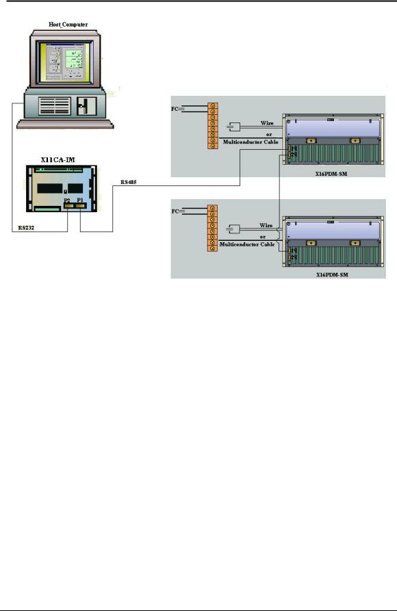
The Configuration Software runs on a host computer to make it easy for an operator to program and test the X11CA/X16PDM alarm modules.
A basic system consists of three devices: a host computer, X11CA-IM, and X11CA/X16PDM chassis. The serial port of the host computer is connected to the port 2 (P2) of X11CA Interface Module via RS232 serial connection, and the port2 (P2) of the X11CA-IM is connected to the X11CA/X16PDM port via RS484 serial connection.
An X11CA/X16PDM system can have up to 255 modules, and each module must have a unique address set on its J9 switch. However, the maximum number of modules that can be configured by the Configuration Software is 225 at this time.
The X11CA-IM has a switch to set its mode as either PRGM(Program) or Run. When the switch is set to Program mode, the Configuration Software bypasses the X11CA-IM to program and test the module properties in the X11CA/X16PDM chassis. In Run mode, the X11CA-IM takes full control of the X11CA/X16PDM Annunciator modules.
For the hardware settings of the X11CA-IM and the X11CA/X16PDM Annunciator system, refer to the documents, Series X11CA Hardware Manual or Series X16PDM Hardware Manual and X11CA-IM Master Modules.
Figure 1-1 X11CA System
Hardware Control-© 2003 Ronan Engineering |
1 |
Rev 1.3 Series X11CA Computer Annunciators: X11CA Configuration Software User’s Manual
1.Overview
Figure 1-2 X16PDM System
1.1 Abbreviations
AUX |
: Auxiliary Relay |
CTA /CA |
: Common Trouble Alarm |
FC |
: Field Contact |
GF |
: General Function |
H1 |
: Horn 1 |
H2 |
: Horn 2 |
IP |
: Internet Protocol |
NC |
: Not Connected |
PDM |
: Programmable Digital Monitors |
TCP |
: Transport Control Protocol |
TO |
: Transistor Output |
Hardware Control-© 2003 Ronan Engineering |
2 |

Rev 1.3 Series X11CA Computer Annunciators: X11CA Configuration Software User’s Manual
1.Overview
1.2Revision History
Revision 1.0 : First approved and released document
Revision 1.1 : Updated due to software update from V2.0 to
V2.0.50: ECO# 11774
Revision 1.2 : Title includes X16PDM:Added X16PDM: Sec 4.5.
|
user has to save the configuration into CFG file to make |
|
a report ECO#11786 |
Revision 1.3 : Corrected grammar ECO#11823 |
|
1.3 References |
|
QA400 |
: Design Control |
QA4000 |
: Design Development Quality Assurance |
|
Plan |
QA4500 |
: Project Archive |
X11CA-3000 |
: X11CA-IM Master Modules |
X11CA-3002 |
: X11CA Hardware Manual for X11CA |
Or |
system or X16PDM Hardware Manual for |
X16PDM-100-IOM |
16PDM system |
Purchase Order |
|
Hardware Control-© 2003 Ronan Engineering |
3 |

Rev 1.2 Series X11CA Computer Annunciators: X11CA Configuration Software User’s Manual
3. X11CA Installation and Un-installation
2. Requirements
The following is a list of system requirements for installing and running the Configuration Software.
?Windows 95/98/NT/XP Operating System
?The most recent firmware of unit 16 on the X11CA-IM: checksum
?The most recent firmware of unit 2 on each module (part number: X11-1047PL-
1 R1): X11CAV1.0 19200.HEX
Hardware Control-© 2003 Ronan Engineering |
4 |
Rev 1.3 Series X11CA Computer Annunciators: X11CA Configuration Software User’s Manual
3. X11CA Installation and Un-installation
3.Software Installation and Un-installation
3.1Installing the Configuration Software Software
1)Turn on the power to the computer.
2)Close all the other running programs.
3)Insert the Installation CD into the CD driver.
4)Double-click on the My Computer icon on the desktop.
5)Double-click on the CD ROM drive that has the installation disk.
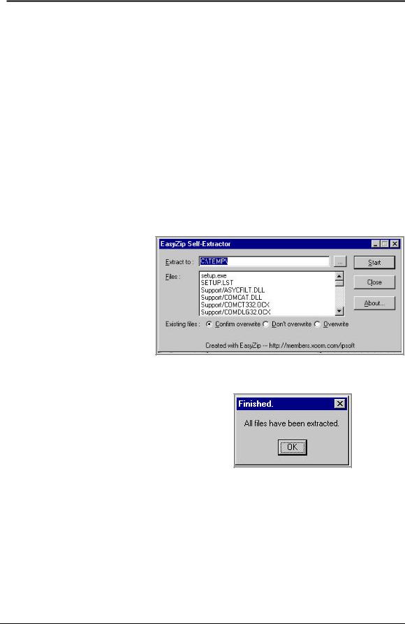
6)Double-click on the X11CA 2 50.EXE zip file. On the EasyZip SelfExtractor window, click on the Start button.
Figure 3-1
Extraction of the
Installation File
When the Finished window opens, click on the OK button.
Figure 3-2 Finished Extraction
When the X11CA Setup window displays, click on the OK button.
7)Double-click on the SETUP icon . The installation program will load installation files. Follow the instructions on the installation CD. When
the X11CA Setup window displays, click on the OK button.
8)The next window will display the destination directory where the software will be loaded.
Hardware Control-© 2003 Ronan Engineering |
5 |
Rev 1.3 Series X11CA Computer Annunciators: X11CA Configuration Software User’s Manual 3. X11CA Installation and Un-installation
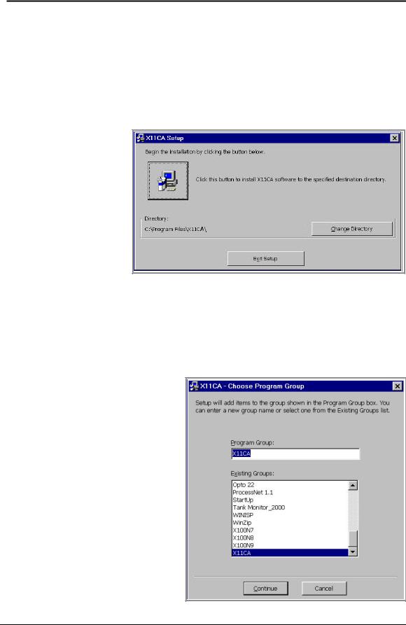
If you want to change the directory, click on the Change Directory button to select a destination directory as shown in Figure 3-3
When you are ready to continue the installation, click on the installation
icon button in the middle of the window to continue the installation. If you do not want the installation at this time, click on the Exit Setup button at the bottom of the window to stop the installation.
Figure 3-3
X11CA
Setup
Window
9)The next window is the X11CA Choose Program Group window (Figure 3-4) where you can set the program name to be displayed in the Programs menu. The default name is ‘X11CA’, but you can either set a new name or choose one from the list of the program names. Press the Continue button to continue with the installation.
Figure 3-4. X11CA-
Choose Program Group
Hardware Control-© 2003 Ronan Engineering |
6 |
Rev 1.3 Series X11CA Computer Annunciators: X11CA Configuration Software User’s Manual
3.X11CA Installation and Un-installation
10)The installation program will install the software. When the X11CA Setup is completed successfully, click on the OK button.
3.2Uninstalling the Configuration Software Software
1)Left-click on the Start button on the desktop.
2)Select the Settings.
3)Select the Control Panel.
4)Double click on the Add/Remove Programs icon.
5)Left-click on the program group name (Example, X11CA) in the list box.
6)Left-click on the Add/Remove button.
7)Follow the instructions on the screen.
Hardware Control-© 2003 Ronan Engineering |
7 |

Rev 1.3 Series X11CA Computer Annunciators: X11CA Configuration Software User’s Manual
4. X11CA Software Operation
4. Configuration Software Operation
The main function of the Configuration Software is easy configuration and testing of the alarm modules in the X11CA/X16PDM chassis. This function involves two types of modules: physical module and logical module.
A physical module is an alarm module in the X11CA/X16PDM chassis. Each physical module has a micro-controller, firmware and a unique system address.
A logical module is a module created dynamically by Configuration Software on the host computer. Because each logical module is configured for its corresponding physical module, its address must be same as its physical module. The logical modules and their properties exist only in the Configuration Software environment where they were created. Therefore, it is better to save them into a CFG file( *.cfg file) before you exit out of the Configuration Software environment.
However, logical modules do not have any affect on physical modules until properties of the logical modules are programmed into their physical modules.
When you request programming a module, the Configuration Software checks your password. After authentication, it sends the logical module properties to the target physical module via X11CA-IM. The micro-controller on the target module saves the properties in its firmware.
When you request retrieving from a physical module, the Configuration Software requests the target physical module to send its properties. After receiving the address and module properties from the physical module via X11CA-IM, it places the properties into the logical module buffer with the matching address.
Once the properties are programmed into the physical module firmware, you can test the properties of the physical modules by setting the logical module into Run mode, and then clicking the push buttons on the Main window of the Configuration Software.
To pass control over the physical modules and other devices from Configuration Software to X11CA-IM, set the switch on X11CA-IM to run mode.
Hardware Control-© 2003 Ronan Engineering |
8 |

Rev 1.3 Series X11CA Computer Annunciators: X11CA Configuration Software User’s Manual
4. X11CA Software Operation
 Example: Figure 4-1 (Module1:3 channels, Module2:4 channels)
Figure 4-1 shows a X11CA system with two physical modules. Each physical module has a unique address. The first module has three channels and the second module has four channels.
Figure 4-1 System Setup
 This example will continue throughout this document. When you see an example that
starts with  icon, you will know that it is the continuation of the example with the same system set up as Fig 4-1.
Hardware Control-© 2003 Ronan Engineering |
9 |
Rev 1.3 Series X11CA Computer Annunciators: X11CA Configuration Software User’s Manual
4.X11CA Software Operation
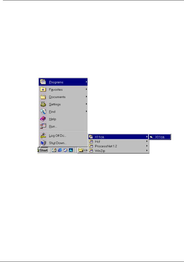
4.1Loading the Configuration Program
1.Click on the Start button.
2.Select Programs.
3.Click on the program name you have selected during the installation process.
The following example shows the program name as X11CA.
Figure 4-2. Starting Configuration Software
4.2The Main Window
After the software is loaded, the Main window opens. It consists of five main areas: Title Bar, Tool Bar, Menu Bar, System-Display area, and Status area.
Hardware Control-© 2003 Ronan Engineering |
10 |

Rev 1.3 Series X11CA Computer Annunciators: X11CA Configuration Software User’s Manual
4. X11CA Software Operation
Figure 4-3 Main Window
4.2.1The Title Bar
The first line at the top of the Main window is the Title area. It displays two names: the Configuration Software name and the configuration file name.
Example: The title bar on Figure 4-3 shows that the name of the program is ‘X11CA’ and the configuration file name is ‘untitled’.
4.2.2The Menu Bar
The second line from the top of the Main window is the Menu area. It has five menus and each menu has its own submenus. Figure 4-4 shows the menus in bold characters and submenus in plain characters.
Hardware Control-© 2003 Ronan Engineering |
11 |

Rev 1.3 Series X11CA Computer Annunciators: X11CA Configuration Software User’s Manual
4. X11CA Software Operation
|
.File |
|
|
Module |
|
|
System |
|
|
Setup |
|
|
Help |
|
|
|
(ALT+F) |
|
|
(ALT+M) |
|
|
(ALT+S) |
|
|
(ALT+E) |
|
|
(ALT+H) |
|
|
|
New |
|
|
Config |
|
|
Config |
|
|
Commport |
|
|
About |
|
|
|
Open (Ctrl+O) |
|
|
|
|
|
|
|
|
Password |
|
|
|
|
|
|
Save (Ctrl+S) |
|
|
Run |
|
|
Connect |
|
|
|
|
|
|
|
|
|
Save As |
|
|
Stop |
|
|
Disconnect |
|
|
|
|
|
|
|
|
|
Access Info |
|
|
Receive |
|
|
Run |
|
|
|
|
|
|
|
|
|
Exit |
|
|
Program |
|
|
Stop |
|
|
|
|
|
|
|
|
|
|
|
|
|
|
|
Receive |
|
|
|
|
|
|
|
|
|
|
|
|
|
|
|
Program |
|
|
|
|
|
|
|
|
|
|
|
|
|
|
|
SaveReportAs |
|
|
|
|
|
|
|
|
|
|
|
|
|
|
|
PrintReport |
|
|
|
|
|
|
|
|
|
|
|
|
|
|
|
|
|
|
|
|
|
|
|
|
Figure 4-4. Menu Bar
File (ALT+F) menu
|
|
|
|
Submenus |
|
Description |
|
New |
|
Opens a new configuration file with default settings. |
|
Open |
|
Displays a list of files to choose from. When a configuration file |
|
|
|
opens, logical modules are set up with the properties saved in the file. |
|
Save |
|
Saves the current system and module properties into the currently |
|
|
|
configuration file. |
|
Save As |
|
Saves current system and module properties into a user-specified file. |
|
Acess Info |
|
Displays information of the current configuration file. |
|
|
|
§ Path and name of the file |
|
|
|
§ Date and time it was created |
|
|
|
§ Date and time it was last accessed |
|
|
|
§ Date and time it was last modified |
|
|
|
(See Figure 4-29 File Access Info Window.) |
|
Exit |
|
Closes Configuration software to return to the desktop. |
|
|
|
Table 4-1 File Menu and Its Submenus |
|
Module (ALT+M) menu
Module menu applies to a single module. Before clicking on the Module menu, click once in a logical module cell on the Main window to select it.
The following is a list of submenus and the results of pressing them.
Hardware Control-© 2003 Ronan Engineering |
12 |

Rev 1.3 Series X11CA Computer Annunciators: X11CA Configuration Software User’s Manual 4. X11CA Software Operation
|
|
|
|
|
|
|
Submenus |
|
|
Description |
|
|
|
|
|
|
|
|
Config |
|
|
Opens Module Properties window. |
|
|
|
|
(See Figure 4-14. Module Properties Window.) |
|
|
|
|
|
|
|
|
|
|
|
|
The highlighted logical module cell on the Main window that has |
|
|
|
|
|
communication with its physic al module becomes green and displays |
|
|
|
|
|
‘Run’ message. |
|
|
|
|
|
(See Figure 4-33. Modules in Run Mode.) |
|
|
Run |
|
|
If connection to the physical modules is active, the physical module is |
|
|
|
|
|
ready to be tested. |
|
|
|
|
|
The logical module that fails to establish communication with its |
|
|
|
|
|
physical module displays the message, ‘NoComm’ displays on its |
|
|
|
|
|
white cell. |
|
|
|
|
|
The highlighted logical module cell on the Main window displays |
|
|
|
|
|
‘Stop’ message over the red background. |
|
|
|
|
|
(See Figure 4-34 Modules in Stop Mode.) |
|
|
|
|
|
If connection to the physical modules is active, its physical module is |
|
|
Stop |
|
|
ready for programming or for sending a copy of its properties to its |
|
|
|
|
|
logical module. |
|
|
|
|
|
The logical module that fails to establish communication with its |
|
|
|
|
|
physical module displays the message, ‘NoComm’ displays on its |
|
|
|
|
|
white cell. |
|
|
|
|
|
If connected and the highlighted logical module is in Stop mode, it |
|
|
|
|
|
receives properties from its physical module. |
|
|
Receive |
|
|
The logical module that fails to establish communication with its |
|
|
|
|
|
|
|
|
|
|
|
physical module displays the message, ‘NoComm’ displays on its |
|
|
|
|
|
white cell. |
|
|
|
|
|
If connected, and the highlighted logical module is in Stop mode, an |
|
|
|
|
|
authorized user can program properties of a logical module into its |
|
|
Program |
|
|
physical module. |
|
|
|
|
The logical module that fails to establish communication with its |
|
|
|
|
|
|
|
|
|
|
|
|
physical module displays the message, ‘NoComm’ displays on its |
|
|
|
|
|
white cell. |
|
|
|
|
Table 4-2 Module Menu and Its Submenus |
|
|
SYSTEM (ALT+S) menu
Unlike the Module menu, the System menu applies to all the modules in the system.
Hardware Control-© 2003 Ronan Engineering |
13 |

Rev 1.3 Series X11CA Computer Annunciators: X11CA Configuration Software User’s Manual 4. X11CA Software Operation
|
|
Submenu |
Description |
Config |
Opens Module Properties window. |
|
(See Figure 4-14. Module Properties Window.) |
|
This function is same as the Config submenu of Module menu. |
Connect |
Makes connection between the logical modules and the physical |
|
modules. |
Disconnect |
Disconnects from the physical modules. |
Run |
Each logical module cell on the Main window that has communication |
|
with its physical module becomes green and displays ‘Run’ message. |
|
(See Figure 4-33. Modules in Run Mode.) |
|
If connection to the physical modules is active, the physical module is |
|
ready to be tested. |
|
The logical module that fails to establish communication with its |
|
physical module displays the message, ‘NoComm’ displays on its |
|
white cell. |
Stop |
Each logical module cell on the Main window displays ‘Stop’ message |
|
over the red background. |
|
(See Figure 4-34 Modules in Stop Mode.) |
|
If connection to the physical modules is active, its physical module is |
|
ready for programming or for sending a copy of its properties to its |
|
logical module. |
|
The logical module that fails to establish communication with its |
|
physical module displays the message, ‘NoComm’ displays on its |
|
white cell. |
Receive |
If connected, the logical modules that are in Stop mode receive copies |
|
of properties from their physical modules. |
|
The logical module that fails to establish communication with its |
|
physical module displays the message, ‘NoComm’ displays on its |
|
white cell. |
Program |
If connected, and the logical modules are in Stop mode, an authorized |
|
user can program properties of the logical modules into their |
|
corresponding physical modules. |
|
The logical module that fails to establish communication with its |
|
physical module displays the message, ‘NoComm’ displays on its |
|
white cell. |
SaveReportAs |
Opens a Save As window where the system report file name can be |
|
changed. |
PrintReport |
Sends the content of currently open report file to the default printer. |
|
Table 4-3 System Submenu |
Hardware Control-© 2003 Ronan Engineering |
14 |
Rev 1.3 Series X11CA Computer Annunciators: X11CA Configuration Software User’s Manual
4. X11CA Software Operation
SETUP (ALT+E) menu
|
|
|
|
Submenu |
|
Description |
|
CommPort |
|
Opens Setup window where you can set up the communication port |
|
|
|
and its baud rate. |
|
|
|
(See Figure 4-9 Communication Port Window.) |
|
Password |
|
Opens Set Password window where you can change the password for |
|
|
|
programming the micro-controllers. (See Figure 4-40. Set Password |
|
|
|
Window.) |
|
|
|
Table 4-4 Setup Submenu |
|
HELP (ALT+H) menu
|
Submenu |
|
|
Description |
|
|
About |
|
|
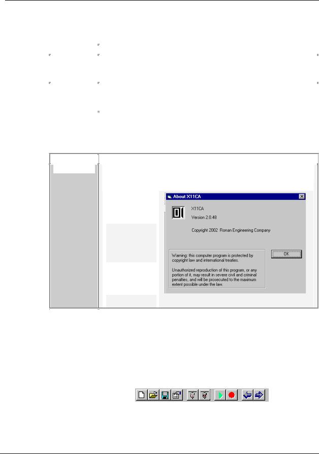
Opens About X11CA window that displa ys the information about the |
|
|
|
|
|
software, such as the version number. |
|
|
|
|
|
|
|
Figure 4-5
About
Submenu
Table 4-5 Help Submenu
4.2.3The Tool Bar
The third line from the top of the Main window is the tool bar.
Figure 4-6 Icons
Hardware Control-© 2003 Ronan Engineering |
15 |

Rev 1.3 Series X11CA Computer Annunciators: X11CA Configuration Software User’s Manual
4. X11CA Software Operation
If you place the cursor underneath each icon, its name will display under the icon.
|
|
|
|
|
|
|
Name |
|
|
Description |
|
|
New |
|
|
Opens a new configuration file. Pressing this button also resets the |
|
|
|
|
Configuration Software. |
|
|
|
Open |
|
|
Opens a window that has a list of existing files to be selected from. |
|
|
|
|
|
|
|
|
|
|
|
Saves the current properties into the currently open configuration |
|
|
Save |
|
|
file. |
|
|
Properties |
|
|
Opens a Module Properties window of the selected logical |
|
|
|
|
module. See Figure 4-14. Module Properties Window. |
|
|
|
|
|
|
|
|
|
Connect |
|
|
Makes connection between logical modules and their |
|
|
|
|
corresponding physical alarm modules. The logical module that |
|
|
|
|
|
|
failed to establish communication with its physical module |
|
|
|
|
|
displays ‘NoComm’ message in its cell. |
|
|
Disconnect |
|
|
Disconnects logical modules from their physical alarm modules. |
|
|
|
|
|
|
|
|
|
|
|
|
|
|
Run |
|
|
Same as the Run submenu of System menu. |
|
|
|
|
|
|
|
|
Stop |
|
|
Same as the Stop submenu of System menu. |
|
|
|
|
|
|
|
|
Program |
|
|
Same as the Program submenu of the Module menu. |
|
|
|
|
|
|
|
|
Receive |
|
|
Same as the Receive submenu of the Module menu |
|
|
|
|
|
|
|
|
|
|
|
Table 4-6 Tool Bar |
|
4.2.4System Display Field
The System Display area is composed of three fields.
§Module Display table field
§Module Status field
§Push Button Field
Example: Figure 4-7 System Display Field shows System Display area with 225 logical modules. The number in each cell is its logical module addresses. When the logical module cell number 225 is selected, its module number, its status, and sequence types of its channels display on the Module Status area.
Hardware Control-© 2003 Ronan Engineering |
16 |
 Loading...