

Page 1
Page 2

Page 3
WARNING: To reduce the risk of fire or electric shock, do not expose this apparatus to rain or moisture.
CAUTION
RISK OF ELECTRIC SHOCK
DO NOT OPEN
ATTENTION: RISQUE DE CHOC ELECTRIQUE NE PAS OUVRIR
CAUTION: TO REDUCE THE RISK OF ELECTRIC SHOCK,
DO NOT REMOVE COVER (OR BACK).
NO USER-SERVICEABLE PARTS INSIDE.
REFER SERVICING TO QUALIFIED SERVICE PERSONNEL.
The lightning flash with arrowhead symbol, within an
equilateral triangle, is intended to alert the user to the
presence of uninsulated “dangerous voltage” within the
product’s enclosure that may be of sufficient magnitude to
constitute a risk of electric shock to persons.
The exclamation point within an equilateral triangle is
intended to alert the user to the presence of important
operating and maintenance (servicing) instructions in the
literature accompanying the product.
INSTRUCTIONS PERTAINING TO A RISK OF FIRE, ELECTRIC SHOCK, OR INJURY TO PERSONS.
IMPORTANT SAFETY INSTRUCTIONS
SAVE THESE INSTRUCTIONS
WARNING - When using electric products, basic precautions should always be followed, including the following:
1. Read these instructions.
2. Keep these instructions.
3. Heed all warnings.
4. Follow all instructions.
5. Do not use this apparatus near water.
6. Clean only with a dry cloth.
7. Do not block any of the ventilation openings. Install in
accordance with the manufacturers instructions.
8. Do not install near any heat sources such as radiators,
heat registers, stoves, or other apparatus (including
amplifiers) that produce heat.
9. Do not defeat the safety purpose of the polarized or
grounding-type plug. A polarized plug has two blades with
one wider than the other. A grounding type plug has two
blades and a third grounding prong. The wide blade or the
third prong are provided for your safety. If the provided plug
does not fit into your outlet, consult an electrician for
replacement of the obsolete outlet.
10. Protect the power cord from being walked on or pinched
particularly at plugs, convenience receptacles, and the
point where they exit from the apparatus.
11. Only use attachments/accessories specified by the
manufacturer.
12. Use only with the cart, stand, tripod, bracket,
or table specified by the manufacturer, or
sold with the apparatus. When a cart is used,
use caution when moving the cart/apparatus
combination to avoid injury from tip-over.
13. Unplug this apparatus during lightning storms or when
unused for long periods of time.
14. Refer all servicing to qualified service personnel. Servicing
is required when the apparatus has been damaged in any
way, such as power-supply cord or plug is damaged, liquid
has been spilled or objects have fallen into the apparatus,
the apparatus has been exposed to rain or moisture, does
not operate normally, or has been dropped.
For the U.K.
WARNING:
IMPORTANT:
As the colours of the wires in the mains lead of this apparatus may not correspond with the coloured markings identifying
the terminals in your plug, proceed as follows:
The wire which is coloured GREEN-AND-YELLOW must be connected to the terminal in the plug which is marked by the
letter E or by the safety earth symbol or coloured GREEN or GREEN-AND-YELLOW.
The wire which is coloured BLUE must be connected to the terminal which is marked with the letter N or coloured BLACK.
The wire which is coloured BROWN must be connected to the terminal which is marked with the letter L or coloured RED.
Before using this unit, carefully read the sections entitled: “IMPORTANT SAFETY INSTRUCTIONS”, “USING THE UNIT
SAFELY” (p. 4), and “IMPORTANT NOTES” (p. 6). These sections provide important information concerning the proper
operation of the unit. Additionally, in order to feel assured that you have gained a good grasp of every feature provided by
your new unit, this owner’s manual should be read in its entirety. The manual should be saved and kept on hand as a
convenient reference.
Copyright © 2010 ROLAND CORPORATION
All rights reserved. No part of this publication may be reproduced in any form without the written permission of ROLAND CORPORATION.
Roland is a registered trademark of ROLAND CORPORATION in the United States and/or other countries.
THIS APPARATUS MUST BE EARTHED
THE WIRES IN THIS MAINS LEAD ARE COLOURED IN ACCORDANCE WITH THE FOLLOWING CODE.
GREEN-AND-YELLOW: EARTH, BLUE: NEUTRAL, BROWN: LIVE
Page 4
USING THE UNIT SAFELY
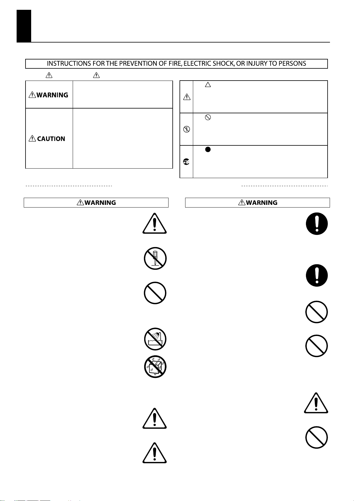
About WARNING and CAUTION Notices
Used for instructions intended to alert the
user to the risk of death or severe injury
should the unit be used improperly.
Used for instructions intended to alert the
user to the risk of injury or material
damage should the unit be used
improperly.
* Material damage refers to damage or
other adverse effects caused with
respect to the home and all its
furnishings, as well to domestic animals
or pets.
ALWAYS OBSERVE THE FOLLOWING
•
Connect mains plug of this model to a mains socket
outlet with a protective earthing connection.
..................................................................................................................................
• Do not open or perform any internal modifications on
the unit.
..................................................................................................................................
•
Do not attempt to repair the unit, or replace parts
within it (except when this manual provides specific
instructions directing you to do so). Refer all servicing
to your retailer, the nearest Roland Service Center, or an
authorized Roland distributor, as listed on the
“Information” page.
..................................................................................................................................
• Never install the unit in any of the following locations.
• Subject to temperature extremes (e.g., direct
sunlight in an enclosed vehicle, near a heating duct,
on top of heat-generating equipment); or are
• Damp (e.g., baths, washrooms, on wet floors); or are
• Exposed to steam or smoke; or are
• Subject to salt exposure; or are
• Humid; or are
• Exposed to rain; or are
• Dusty or sandy; or are
• Subject to high levels of vibration and shakiness.
..................................................................................................................................
This unit should be used only with a stand that is
•
recommended by Roland.
..................................................................................................................................
The unit should be connected to a power supply only
•
of the type described as marked on the rear side of
unit.
About the Symbols
The symbol alerts the user to important instructions or
warnings.The specific meaning of the symbol is
determined by the design contained within the triangle. In
the case of the symbol at left, it is used for general
cautions, warnings, or alerts to danger.
The symbol alerts the user to items that must never be
carried out (are forbidden). The specific thing that must
not be done is indicated by the design contained within
the circle. In the case of the symbol at left, it means that
the unit must never be disassembled.
The symbol alerts the user to things that must be
carried out. The specific thing that must be done is
indicated by the design contained within the circle. In the
case of the symbol at left, it means that the power-cord
plug must be unplugged from the outlet.
•
When using the unit with a stand recommended by
Roland, the rack or stand must be carefully placed so it
is level and sure to remain stable. If not using a rack or
stand, you still need to make sure that any location you
choose for placing the unit provides a level surface that
will properly support the unit, and keep it from
wobbling.
..................................................................................................................................
•
Use only the attached power-supply cord. Also, the
supplied power cord must not be used with any other
device.
..................................................................................................................................
• Do not excessively twist or bend the power cord, nor
place heavy objects on it. Doing so can damage the
cord, producing severed elements and short circuits.
Damaged cords are fire and shock hazards!
..................................................................................................................................
This unit, either alone or in combination with an
•
amplifier and headphones or speakers, may be capable
of producing sound levels that could cause permanent
hearing loss. Do not operate for a long period of time at
a high volume level, or at a level that is uncomfortable.
If you experience any hearing loss or ringing in the ears,
you should immediately stop using the unit, and
consult an audiologist.
..................................................................................................................................
In households with small children, an adult should
•
provide supervision until the child is capable of
following all the rules essential for the safe operation
of the unit.
..................................................................................................................................
Protect the unit from strong impact.
•
(Do not drop it!)
..................................................................................................................................
..................................................................................................................................
4
Page 5
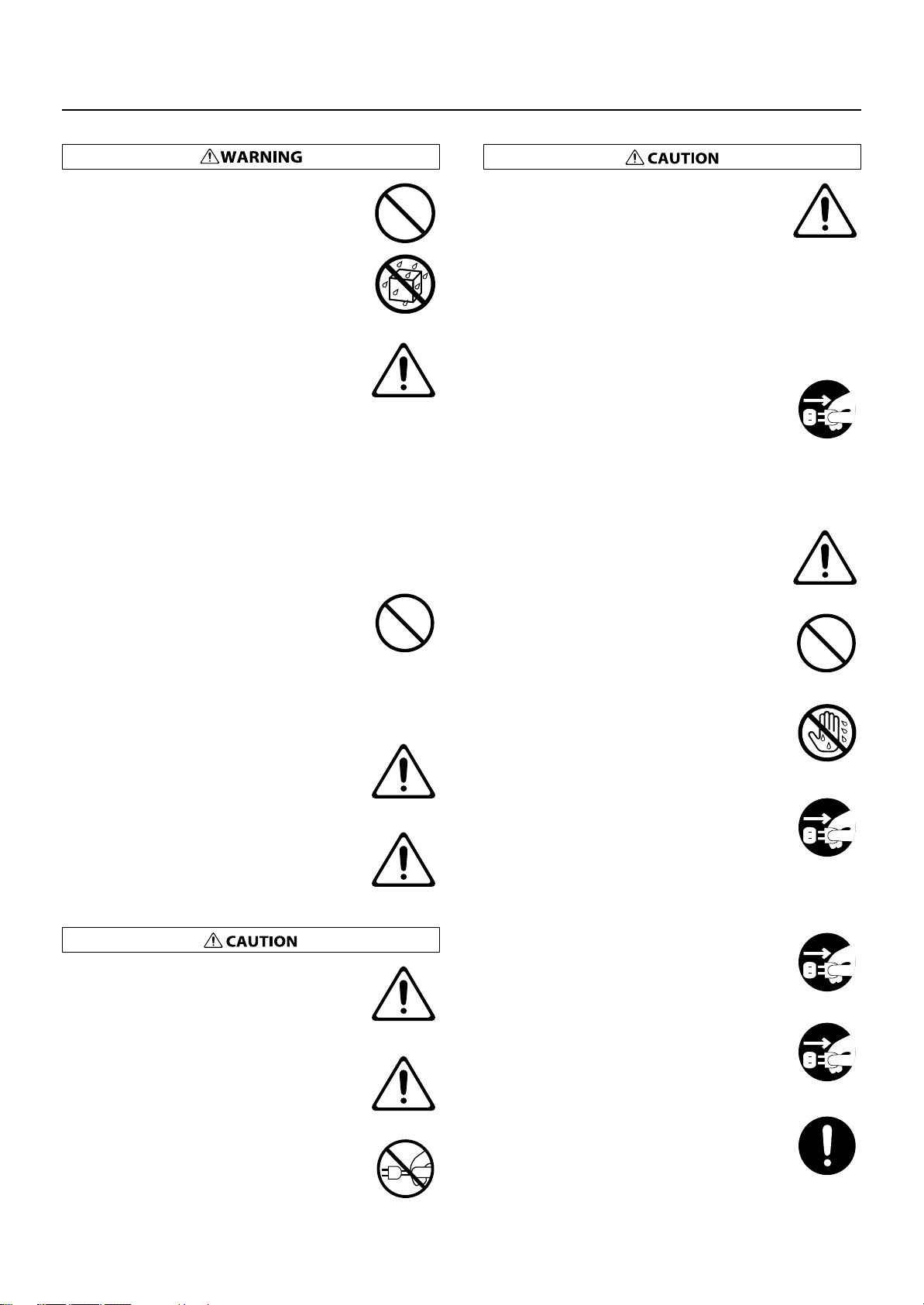
USING THE UNIT SAFELY
Do not allow any objects (e.g., flammable material,
•
coins, pins); or liquids of any kind (water, soft drinks,
etc.) to penetrate the unit.
..................................................................................................................................
Immediately turn the power off, remove the power
•
cord from the outlet, and request servicing by your
retailer, the nearest Roland Service Center, or an
authorized Roland distributor, as listed on the
“Information” page when:
• The power-supply cord or the plug has been
damaged; or
• If smoke or unusual odor occurs
• Objects have fallen into, or liquid has been spilled
onto the unit; or
• The unit has been exposed to rain (or otherwise has
become wet); or
• The unit does not appear to operate normally or
exhibits a marked change in performance.
..................................................................................................................................
Do not force the unit’s power-supply cord to share an
•
outlet with an unreasonable number of other devices.
Be especially careful when using extension cords—the
total power used by all devices you have connected to
the extension cord’s outlet must never exceed the
power rating (watts/amperes) for the extension cord.
Excessive loads can cause the insulation on the cord to
heat up and eventually melt through.
..................................................................................................................................
Before using the unit in a foreign country, consult with
•
your retailer, the nearest Roland Service Center, or an
authorized Roland distributor, as listed on the
“Information” page.
..................................................................................................................................
•
Do not put anything that contains water (e.g., flower
vases) on this unit. Also, avoid the use of insecticides,
perfumes, alcohol, nail polish, spray cans, etc., near the
unit. Swiftly wipe away any liquid that spills on the unit
using a dry, soft cloth.
• The unit should be located so that its location or
position does not interfere with its proper ventilation.
..................................................................................................................................
This (VR-700) for use only with Roland stand KS-G8. Use
•
with other stands is capable of resulting in instability
causing possible injury.
..................................................................................................................................
Always grasp only the plug on the power-supply cord
•
when plugging into, or unplugging from, an outlet or
this unit.
..................................................................................................................................
Please be sure to read and adhere to the cautionary
•
notices contained in the instructions that came with
this product.
Please note that, depending on the manner in which
keyboard performances are carried out, you may
encounter situations where the keyboard falls off the
stand or the stand topples over, even though you have
followed all of the instructions and advice contained
within the product’s manual. For this reason, you
should always perform a safety check each time you
use the stand.
..................................................................................................................................
At regular intervals, you should unplug the power plug
•
and clean it by using a dry cloth to wipe all dust and
other accumulations away from its prongs. Also,
disconnect the power plug from the power outlet
whenever the unit is to remain unused for an extended
period of time. Any accumulation of dust between the
power plug and the power outlet can result in poor
insulation and lead to fire.
..................................................................................................................................
Try to prevent cords and cables from becoming
•
entangled. Also, all cords and cables should be placed
so they are out of the reach of children.
..................................................................................................................................
Never climb on top of, nor place heavy objects on the
•
unit.
..................................................................................................................................
Never handle the power cord or its plugs with wet
•
hands when plugging into, or unplugging from, an
outlet or this unit.
..................................................................................................................................
•
If you need to move the instrument, disconnect the
power cord and all cords coming from external devices.
At least two persons are required to safely lift and move
the unit. It should be handled carefully, all the while
keeping it level. Make sure to have a firm grip, to
protect yourself from injury and the instrument from
damage.
..................................................................................................................................
•
Before cleaning the unit, turn off the power and unplug
the power cord from the outlet (p. 18).
..................................................................................................................................
•
Whenever you suspect the possibility of lightning in
your area, pull the plug on the power cord out of the
outlet.
..................................................................................................................................
Should you remove music rest attachment screws, keep
•
them in a safe place out of children’s reach, so there is
no chance of them being swallowed accidentally.
..................................................................................................................................
5
Page 6

IMPORTANT NOTES
Power Supply
• Do not connect this unit to same electrical outlet that is being used by
an electrical appliance that is controlled by an inverter (such as a
refrigerator, washing machine, microwave oven, or air conditioner), or
that contains a motor. Depending on the way in which the electrical
appliance is used, power supply noise may cause this unit to
malfunction or may produce audible noise. If it is not practical to use a
separate electrical outlet, connect a power supply noise filter between
this unit and the electrical outlet.
• Before connecting this unit to other devices, turn off the power to all
units. This will help prevent malfunctions and/or damage to speakers
or other devices.
• Although the LEDs are switched off when the POWER switch is
switched off, this does not mean that the unit has been completely
disconnected from the source of power. If you need to turn off the
power completely, first turn off the POWER switch, then unplug the
power cord from the power outlet. For this reason, the outlet into
which you choose to connect the power cord’s plug should be one
that is within easy reach and readily accessible.
Placement
• Using the unit near power amplifiers (or other equipment containing
large power transformers) may induce hum. To alleviate the problem,
change the orientation of this unit; or move it farther away from the
source of interference.
• This device may interfere with radio and television reception. Do not
use this device in the vicinity of such receivers.
• Noise may be produced if wireless communications devices, such as
cell phones, are operated in the vicinity of this unit. Such noise could
occur when receiving or initiating a call, or while conversing. Should
you experience such problems, you should relocate such wireless
devices so they are at a greater distance from this unit, or switch them
off.
• Do not expose the unit to direct sunlight, place it near devices that
radiate heat, leave it inside an enclosed vehicle, or otherwise subject it
to temperature extremes. Also, do not allow lighting devices that
normally are used while their light source is very close to the unit (such
as a piano light), or powerful spotlights to shine upon the same area of
the unit for extended periods of time. Excessive heat can deform or
discolor the unit.
• When moved from one location to another where the temperature
and/or humidity is very different, water droplets (condensation) may
form inside the unit. Damage or malfunction may result if you attempt
to use the unit in this condition. Therefore, before using the unit, you
must allow it to stand for several hours, until the condensation has
completely evaporated.
Maintenance
• To clean the unit, use a dry, soft cloth; or one that is slightly dampened.
Try to wipe the entire surface using an equal amount of strength,
moving the cloth along with the grain of the wood. Rubbing too hard
in the same area can damage the finish.
• Never use benzine, thinners, alcohol or solvents of any kind, to avoid
the possibility of discoloration and/or deformation.
Repairs and Data
• Please be aware that all data contained in the unit’s memory may be
lost when the unit is sent for repairs. Important data should always be
backed up on a USB memory, or written down on paper (when
possible). During repairs, due care is taken to avoid the loss of data.
However, in certain cases (such as when circuitry related to memory
itself is out of order), we regret that it may not be possible to restore
the data, and Roland assumes no liability concerning such loss of data.
Before Using USB Memories
• Carefully insert the USB memory all the way in—until it is firmly in
place.
• Never touch the terminals of the USB memory. Also, avoid getting the
terminals dirty.
• USB memories are constructed using precision components; handle
the USB memories carefully, paying particular note to the following.
• To prevent damage to the USB memories from static electricity, be
sure to discharge any static electricity from your own body before
handling the USB memories.
• Do not touch or allow metal to come into contact with the contact
portion of the USB memories.
• Do not bend, drop, or subject USB memories to strong shock or
vibration.
• Do not keep USB memories in direct sunlight, in closed vehicles, or
other such locations.
• Do not allow USB memories to become wet.
• Do not disassemble or modify the USB memories.
• Do not allow rubber, vinyl, or similar materials to remain on the unit for
long periods of time. Such objects can discolor or otherwise harmfully
affect the finish.
• Do not allow objects to remain on top of the keyboard. This can be the
cause of malfunction, such as keys ceasing to produce sound.
• Do not paste stickers, decals, or the like to this instrument. Peeling
such matter off the instrument may damage the exterior finish.
• Depending on the material and temperature of the surface on which
you place the unit, its rubber feet may discolor or mar the surface.
You can place a piece of felt or cloth under the rubber feet to prevent
this from happening. If you do so, please make sure that the unit will
not slip or move accidentally.
6
Page 7
Additional Precautions
• Please be aware that the contents of memory can be irretrievably lost
as a result of a malfunction, or the improper operation of the unit. To
protect yourself against the risk of loosing important data, we
recommend that you periodically save a backup copy of important
data you have stored in the unit’s memory on a USB memory.
• Unfortunately, it may be impossible to restore the contents of data
that was stored on a USB memory, or in the unit’s memory once it has
been lost. Roland Corporation assumes no liability concerning such
loss of data.
• Use a reasonable amount of care when using the unit’s buttons,
sliders, or other controls; and when using its jacks and connectors.
Rough handling can lead to malfunctions.
• When connecting / disconnecting all cables, grasp the connector
itself—never pull on the cable. This way you will avoid causing shorts,
or damage to the cable’s internal elements.
• A small amount of heat will radiate from the unit during normal
operation.
• To avoid disturbing your neighbors, try to keep the unit’s volume at
reasonable levels. You may prefer to use headphones, so you do not
need to be concerned about those around you (especially when it is
late at night).
• When you need to transport the unit, package it in the box (including
padding) that it came in, if possible. Otherwise, you will need to use
equivalent packaging materials.
• Do not apply undue force to the music stand while it is in use.
• Use only the specified expression pedal (EV-5 or EV-7; sold separately).
By connecting any other expression pedals, you risk causing
malfunction and/or damage to the unit.
IMPORTANT NOTES
• The usable range of D Beam controller will become extremely small
when used under strong direct sunlight. Please be aware of this when
using the D Beam controller outside.
• The sensitivity of the D Beam controller will change depending on the
amount of light in the vicinity of the unit. If it does not function as you
expect, adjust the sensitivity as appropriate for the brightness of your
location.
* is either registered trademark or trademark of Roland
Corporation in the United States and/or other countries.
* MPEG Layer-3 audio compression technology is licensed
from Fraunhofer IIS Corporation and THOMSON Multimedia
Corporation.
* MMP (Moore Microprocessor Portfolio) refers to a patent
portfolio concerned with microprocessor architecture, which
was developed by Technology Properties Limited (TPL).
Roland has licensed this technology from the TPL Group.
* All product names mentioned in this document are
trademarks or registered trademarks of their respective
owners.
7
Page 8

Contents
USING THE UNIT SAFELY ................................................................................4
IMPORTANT NOTES ........................................................................................6
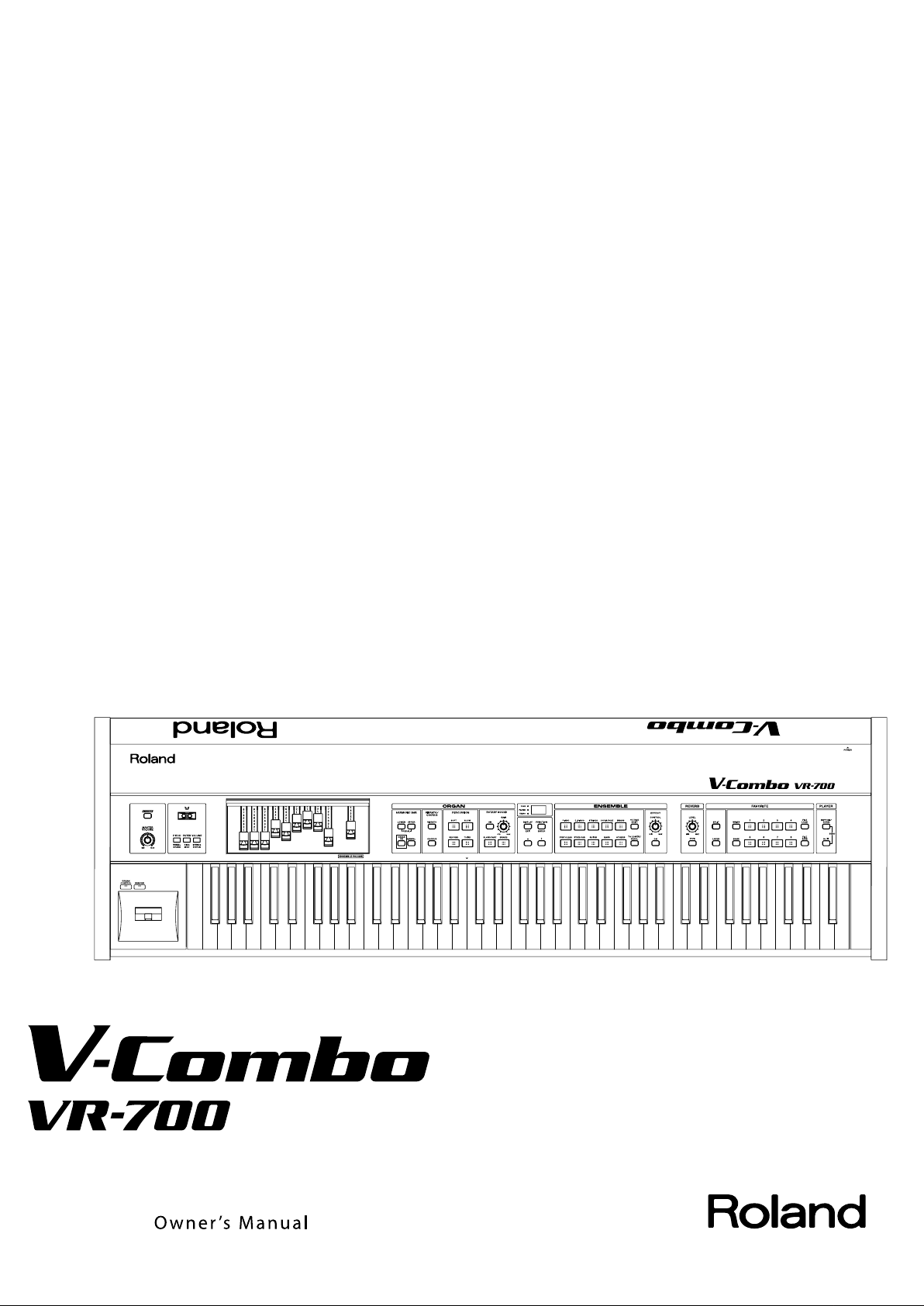
Features of the VR-700 ................................................................................ 12
Names of Things and What They Do .......................................................... 14
Top Panel....................................................................................................................................................................................14
Rear Panel...................................................................................................................................................................................17
Getting Ready .............................................................................................. 18
Placing the VR-700 on the KS-G8 Stand ..........................................................................................................................18
Connecting the Power Cord................................................................................................................................................18
Turning the Power On/Off....................................................................................................................................................19
Turning the Power On..............................................................................................................................................19
Turning the Power Off..............................................................................................................................................19
Connecting Pedals ..................................................................................................................................................................20
Connecting a Pedal Keyboard...............................................................................................................................20
Connecting an Expression Pedal and Damper Pedal ...................................................................................20
Connecting Playback Equipment......................................................................................................................................21
Connecting an Amp and Speakers......................................................................................................................21
Connecting Headphones........................................................................................................................................21
Connecting USB Memory .....................................................................................................................................................22
Attaching the Music Rest......................................................................................................................................................22
Adjusting the Volume............................................................................................................................................................23
Listening to the Demo Songs..............................................................................................................................................23
Indications in the Display .....................................................................................................................................................24
Disabling Panel Operations (Lock Function) .................................................................................................................25
Controls That can be Operated Even While Locked......................................................................................25
Turning the Lock Function On/Off ......................................................................................................................25
Restoring the Factory Settings (Factory Reset).............................................................................................................26
Playing the VR-700 ...................................................................................... 27
About the VR-700’s Parts ......................................................................................................................................................27
Upper Part ....................................................................................................................................................................27
Lower Part.....................................................................................................................................................................27
Pedal Part......................................................................................................................................................................28
Organ Sounds and Ensemble Sounds..............................................................................................................................28
Playing Organ Sounds and Ensemble Sounds Together (Layer)............................................................................29
Layering Ensemble Sounds....................................................................................................................................29
Layering Two Ensemble Sounds ..........................................................................................................................30
Playing Organ Sounds or Ensemble Sounds Individually.........................................................................................33
Playing Only an Ensemble Sound........................................................................................................................33
Playing Only the Organ Sound .............................................................................................................................33
Playing the Sounds of Two Parts on the Keyboard (Split) ........................................................................................34
Boundary Between Upper and Lower Parts (Split Point) ............................................................................35
Using the D Beam Controller to Modify the Sound ....................................................................................................36
D Beam Effects ............................................................................................................................................................36
8
Page 9

Creating Organ Sounds............................................................................... 38
About Virtual Tonewheel Sound Generators ................................................................................................................38
Varying the Sound in Real Time (Harmonic Bars) ........................................................................................................38
Using the Harmonic Bars to Create Sounds .....................................................................................................39
Harmonic Bars and Overtones ..............................................................................................................................39
Using Percussion to add a Sense of Attack ....................................................................................................................41
Adding Modulation to the Sound (Vibrato and Chorus)...........................................................................................42
Turning on Vibrato or Chorus................................................................................................................................42
Changing the Vibrato or Chorus Type ...............................................................................................................42
Adding Rotary Speaker Modulation .................................................................................................................................43
Making the Sound Distort.......................................................................................................................................44
Adding Reverberation (Reverb)..........................................................................................................................................44
Changing the Reverb Type.....................................................................................................................................44
Using a Pedal to Adjust the Volume.................................................................................................................................45
Playing Ensemble Sounds........................................................................... 46
Selecting an Ensemble Sound ............................................................................................................................................46
Octave Shift ...............................................................................................................................................................................46
Effects for the Ensemble Sound .........................................................................................................................................46
Storing Your Favorite Settings (Favorites)................................................ 47
Selecting a Favorite ................................................................................................................................................................47
Saving the Current Settings as a Favorite.......................................................................................................................47
Initializing the Favorites........................................................................................................................................................47
Backing up Favorites to USB Memory..............................................................................................................................48
Restoring from USB Memory...............................................................................................................................................48
Playing Rhythms and Songs (Player Functions)........................................ 49
Playing Internal Rhythms......................................................................................................................................................49
Playing Songs from USB Memory......................................................................................................................................50
Changing the Tempo .............................................................................................................................................................50
Various Settings (Function mode).............................................................. 51
Operations in Function Mode.............................................................................................................................................51
Editing Parameter Values .....................................................................................................................................................51
Confirming System Parameters..........................................................................................................................................51
Parameter List...........................................................................................................................................................................52
Organ Sound Parameters........................................................................................................................................52
Percussion Parameters.............................................................................................................................................52
Rotary Parameters .....................................................................................................................................................53
Ensemble Sound Parameters ................................................................................................................................53
Equalizer Settings ......................................................................................................................................................54
Pedal, Bend Lever, and Foot Controller Settings............................................................................................54
Player Parameters......................................................................................................................................................56
MIDI Input/Output Settings ...................................................................................................................................57
System Settings..........................................................................................................................................................59
V-LINK Settings ...........................................................................................................................................................60
Deleting Favorite Sets, Formatting USB Memory, Initializing the System............................................60
Deleting a Favorite Backup..................................................................................................................................................61
Formatting USB Memory ......................................................................................................................................................62
9
Page 10

Appendix ..............................................................................63
Using V-LINK to Control Video Equipment................................................ 64
Connection Example..............................................................................................................................................................64
Turning V-LINK On/Off...........................................................................................................................................................64
Connecting MIDI Equipment ...................................................................... 65
The VR-700’s Internal Structure..........................................................................................................................................65
Sound Generator Section........................................................................................................................................65
MIDI Routing................................................................................................................................................................65
Connecting an External MIDI Keyboard..........................................................................................................................66
Playing a Desired Part (Factory Settings) ..........................................................................................................66
Playing the Upper Part or Lower Part.................................................................................................................66
Connecting an External MIDI Sequencer........................................................................................................................66
Local Control Setting................................................................................................................................................66
Connecting your Computer.................................................................................................................................................67
Local Control Setting................................................................................................................................................67
Ensemble Sound List ................................................................................... 68
Internal Rhythm Pattern List ...................................................................... 71
List of Effects for the Ensemble Sounds..................................................... 72
List of the Factory Installed Favorites........................................................ 75
Troubleshooting .......................................................................................... 77
Error Messages............................................................................................. 79
Specifications............................................................................................... 80
Index ............................................................................................................. 82
Information .................................................................................................. 86
10
Page 11
* The MIDI implementation is available on Roland’s website.
http://www.roland.com/products/en/
From the above page, proceed to the VR-700 page and download the MIDI implementation.
Convention used in this manual
• Text enclosed in square brackets [ ] indicates the name of a button, such as the [UPPER] button.
• Lines that begin with or an asterisk * are cautionary statements that you must be sure to read.
• (p. **) indicates a reference page.
• The explanations in this manual include illustrations that depict what should typically be shown by the display. Note, however, that your
unit may incorporate a newer, enhanced version of the system (e.g., includes newer sounds), so what you actually see in the display may
not always match what appears in the manual.
11
Page 12
Features of the VR-700
The Pursuit of Excellence—Redefining the Basic Stage Keyboard
An organ, piano, and synthesizer all condensed into a single instrument
A full-fledged organ, high-quality piano, and a synthesizer equipped with all the standard sounds—all of this and more contained in
one easy-to-use, light, compact package. This one instrument is just about all you need for most any live performance; and since it’s
highly portable, you save on the amount of time it takes to get set up for a performance.
•
Creating Organ Sounds..........................................................................................p. 38
•
Selecting an Ensemble Sound .............................................................................p. 46
•
Ensemble Sound List ...............................................................................................p. 68
A total organ sound–from sound generation to sound reinforcement
Equipped with a virtual tone wheel sound generator, which forms the core of the Roland organ sound. In addition, the VR-700 offers a
completely realistic and expressive organ experience, including the characteristic effects and sound reproduction methods of vintage
organs.
•
About Virtual Tonewheel Sound Generators .................................................p. 38
Rotary sound
What would an organ performance be without rotary speakers? The VR-700 faithfully re-creates the sound of rotating speakers,
including the acoustical characteristics of the tweeter (which change depending on the angle), and the way that changes in the speed
of the rotation occur. To enjoy a realistic, rotary sound that is filled with a sense of presence, all you need to do is connect a keyboard
amplifier or powered monitor.
•
Adding Rotary Speaker Modulation ..................................................................p. 43
Overdriven sound
Whether it be the unique characteristics of the vacuum-tube circuitry that was at the heart of the original rotary speakers, the
acoustical properties of the speaker cabinets, or the frequency responses of a variety of amplifiers—all these and more are faithfully
simulated by the VR-700. Simply by switching the amp type, you can enjoy a variety of sounds for your performances—from a warm,
deeply resonating sound to a fat, overdriven sound typical of rock. In addition, for each amp type, you can select from a number of
variations for the drive sound.
•
Making the Sound Distort .....................................................................................p. 44
Enhanced playability thanks to 76-key waterfall keyboard and harmonic bars
With a waterfall keyboard and fast-firing algorithms, the VR-700 is capable of a wide variety of performance techniques, from delicate
glissandos to fast, successive notes. And, it is equipped with nine harmonic bars, which are essential when you want to control the
sound in real time. Thanks to this, a wide variety of organ sounds can be controlled at will. In addition, the VR-700 can essentially be
turned into a two-manual + pedalboard organ—all you need to do is split the keyboard into two zones using the Split function, then
add on an optional PK-25A/7A pedalboard.
12
•
Varying the Sound in Real Time (Harmonic Bars) .........................................p. 38
•
Playing the Sounds of Two Parts on the Keyboard (Split) .........................p. 34
•
Connecting a Pedal Keyboard.............................................................................. p. 20
Page 13
Ensemble section offers high-quality piano and synth sounds
Comes with a stringently selected collection of sounds geared for ensembles. Thanks to the adoption of “88-key multisampling,”
which results in very realistic sounds, you’ll be able to richly express every nuance of your music. Moreover, a wide variety of acoustic
sounds, including analog synthesizers and other electronic musical instruments, and realistic string sounds have also been included,
making it easy for you to contribute a wealth of sounds when playing in a band.
•
Ensemble Sound List ...............................................................................................p. 68
Easy operation—geared for live performances
We’ve placed buttons or knobs right there on the panel for most of functions that a performer needs access to when playing live. And,
since everything has been grouped together according to function, the VR-700 can be controlled simply and logically. Additionally,
we’ve made the buttons self-illuminating, so you don’t need to worry about finding things when you’re on a dark stage. Together, this
means that even the first-time user should experience no problems when using the VR-700, since it’s operation is intuitive.
And, once you have a certain combination of sounds you like, and have made a whole range of detailed settings, you can store your
efforts as a “Favorite,” and have instant access to it later simply by pressing a button.
•
Names of Things and What They Do .................................................................p. 14
•
Storing Your Favorite Settings (Favorites)....................................................... p. 47
Features of the VR-700
Equipped with player feature
The instrument comes stocked with a variety of rhythm patterns, which can be used as a “rhythm guide.” Thanks to this, you can gain
practice along more musical lines, when compared to simply using a metronome.
In addition, the inclusion of a USB memory connector allows you to make use of SMF, WAV, AIFF, and MP3 files stored on USB flash
drives. Such files can be played back when practicing or be used as backing while performing.
•
Playing Rhythms and Songs (Player Functions) ............................................p. 49
Beautifully refined design
The VR-700’s metallic-colored body presents a striking image on stage. And, the distinctive quality of it’s real wood side panels can
only get better with age.
* Like all fine products made of wood, the wooden side panels can be easily scratched. Please treat them with the care they deserve.
13
Page 14
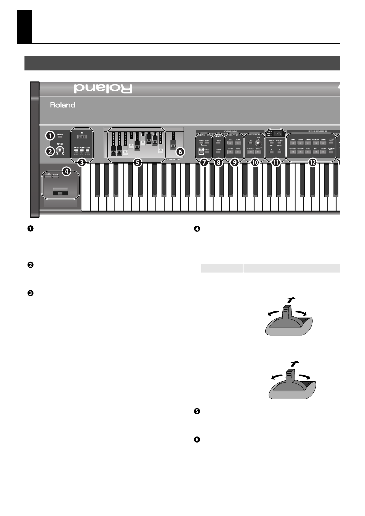
Names of Things and What They Do
Pitch down
Modulation
Pitch up
Top Panel
fig.VR-700Front.eps
[V-LINK] button
This button turns V-LINK on/off (p. 64).
When this is on, the VR-700 can be used to control a V-LINK
compatible video device connected to the VR-700.
[MASTER VOLUME] knob
This knob adjusts the volume of the output from the OUTPUT
connectors on the rear panel and the PHONES jack (p. 23).
D Beam
You can vary the organ sound or ensemble sound by moving your
hand above the D Beam controller (p. 36).
Organ control/Bender lever
You can use the lever to vary the sound in real time.
* The [ORGAN CONTROL] button and [BENDER] button cannot be
turned on simultaneously.
Control
[ORGAN CONTROL]
button
* Only organ
sounds will be
affected.
[BENDER] button
* Only ensemble
sounds will be
affected.
Function
When this button is pressed to turn it on, the lever
will control the organ sound (p. 43).
Pitch up
Change speed of
speaker rotation
If this button is pressed to turn it on, the lever will
vary the pitch of the sound or apply vibrato.
Change speed of
speaker rotation
Harmonic bars
Use these to create the organ sound. You can adjust the tone in real
time while you perform (p. 38).
[ENSEMBLE VOLUME] bar
This adjusts the volume of the ensemble sound (p. 29).
14
Page 15
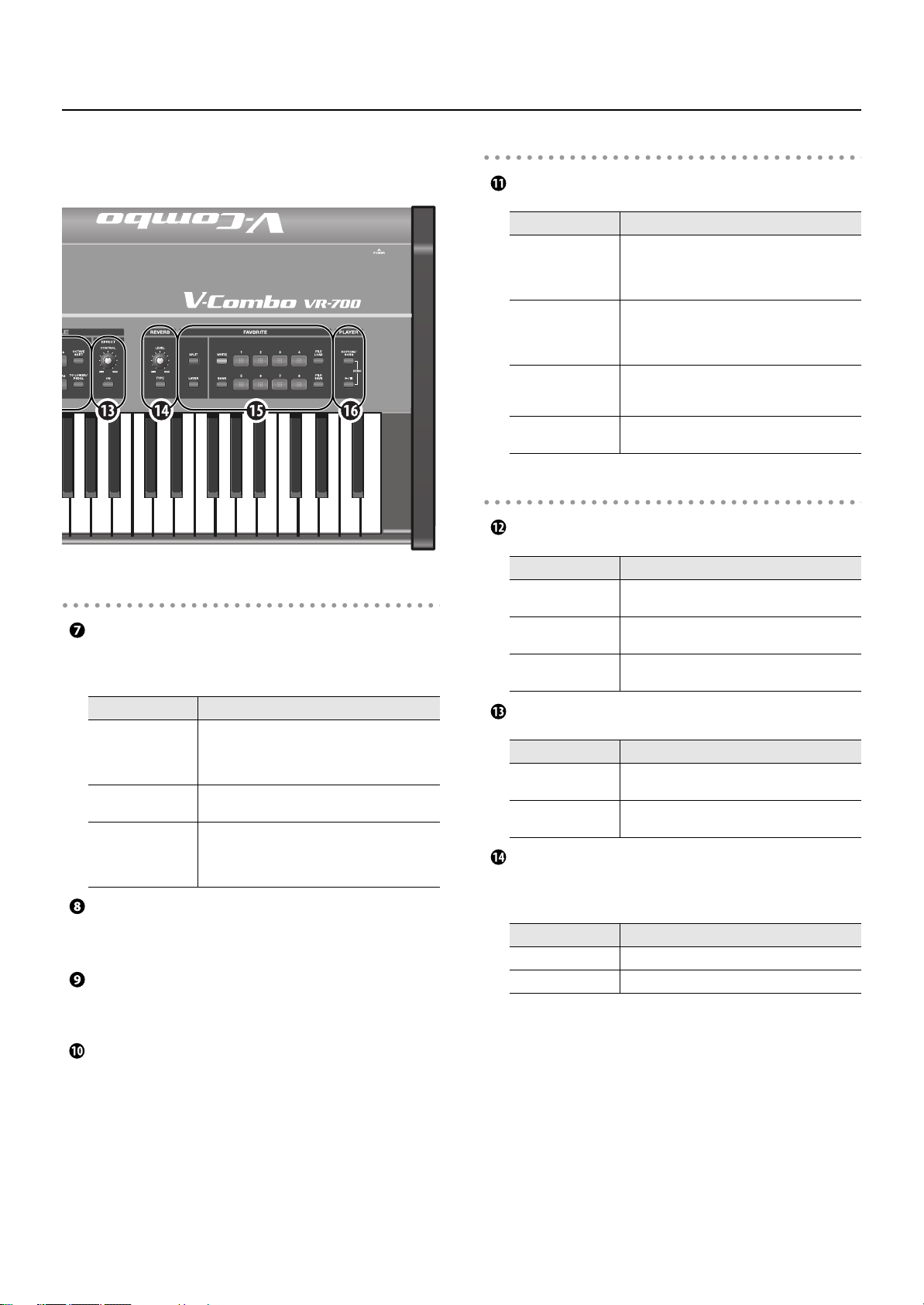
Names of Things and What They Do
fig.VR-700Front.eps
ORGAN section
HARMONIC BAR
Here you can select the part that will reflect the settings of the
harmonic bars (p. 39).
Display section
Display
Control
Display
[DISPLAY/EXIT]
button
[FUNCTION/ENTER]
button
[+] button,
[–] button
ENSEMBLE section
Tone buttons
Control
Tone buttons
[OCTAVE SHIFT]
button
[TO LOWER/PEDAL]
button
Function
This indicates the state of the VR-700 or the
current value of a setting (p. 24).
Indicators for TONE, PLAYER, and TEMPO are
located at the left of the display.
This button changes the content shown in the
display (p. 24). In Function mode, this button
operates as the [EXIT] button to exit Function
mode.
Press this button to switch to Function mode.
In Function mode, this button serves for the
[ENTER] button to execute an operation.
Use these buttons to edit a value.
Function
These buttons select the category of ensemble
sounds (p. 46).
This button sounds the selected ensemble sound
at a higher or lower octave (p. 46).
This sounds the selected ensemble sound in the
lower part or pedal part (p. 29).
Control
[LOWER] button,
[UPPER] button
[ORGAN ON] button
[MANUAL] button
Function
These buttons select the part to which the organ
sound settings of the harmonic bars will apply.
If you press both buttons simultaneously, the
harmonic bars will be assigned to the pedal part.
Switches on/off the production of the organ
sound for all parts.
For the part selected by the [LOWER] button or
[UPPER] button, this button updates the organ
sound of that part to the current state of the
harmonic bars.
VIBRATO/CHORUS
These buttons turn the vibrato and chorus effects on/off for the
organ sound (p. 42).
PERCUSSION
These buttons specify the organ sound’s percussion (the attack
heard when you press a key) (p. 41).
ROTARY SOUND
Here you can specify the rotary effect (the modulation produced by
a rotating speaker) (p. 43).
EFFECT
Control
[CONTROL] knob
[ON] button
Function
This knob adjusts the effect that’s applied to the
ensemble sound (p. 46).
This button turns the effect on/off for the
ensemble sound (p. 46).
REVERB section
Here you can apply reverberation to the organ sounds and
ensemble sounds.
Control
[LEVEL] knob
[TYPE] button Selects the type of reverb effect (p. 44).
Function
Adjusts the depth of the reverb effect (p. 44).
15
Page 16
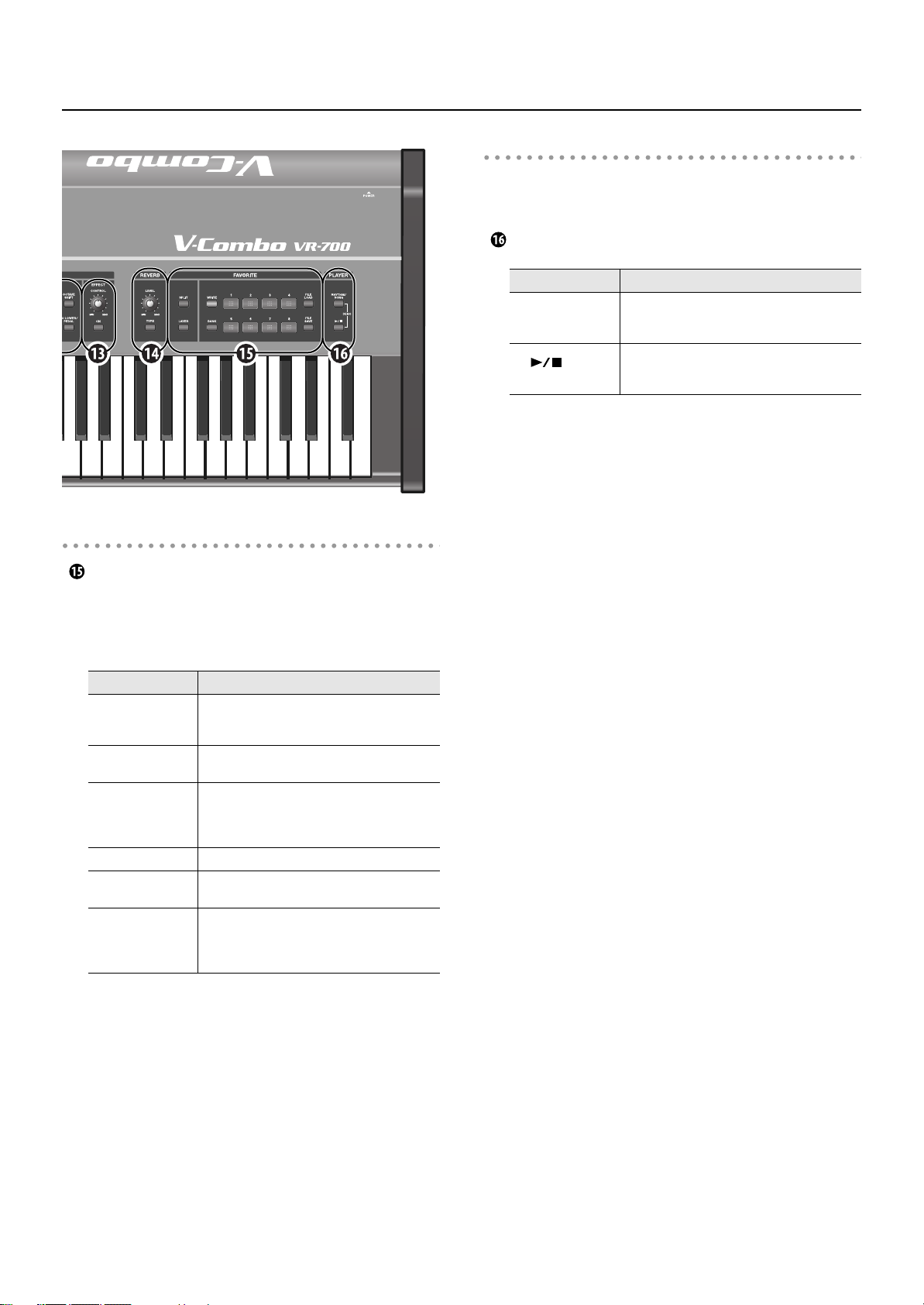
Names of Things and What They Do
fig.VR-700Front.eps
FAVORITE section
FAVORITE
The organ sounds and ensemble sounds that you use frequently,
together with their state, can be registered as Favorites. Once
you’ve registered your favorite settings, you’ll be able to call them
up simply by pressing one of the [FAVORITE] buttons.
PLAYER section
Here you can play back internal rhythm patterns, or MIDI files and
audio files saved on external memory connected to the USB
MEMORY connector.
PLAYER
Control
[RHYTHM/SONG]
button
[
Stop) button
] (Play/
Function
Use this button to specify playback of either
internal rhythm patterns or files stored on
external memory.
This button plays the file.
During playback, pressing this button will stop
playback.
Control
[SPLIT] button
[LAYER] button
[WRITE] button
[BANK] button Use this button to select a bank of favorites (p. 46).
FAVORITE buttons:
[1]–[8]
[FILE LOAD] button
[FILE SAVE] button
Function
This button divides the keyboard into two zones,
allowing you to play a different tone in each zone
(p. 34).
This button allows you to play the ensemble
sound and the organ sound together (p. 29).
Use this button to register the organ sounds,
ensemble sound, and other panel settings as
favorite settings. For details refer to “Saving the
Current Settings as a Favorite” (p. 47).
Use these to callup favorite settings you’ve
registered (p. 46).
These buttons allow you to save or load all the
favorite settings in the VR-700’s internal memory
to or from USB memory connected to the USB
MEMORY connector (p. 48).
16
Page 17
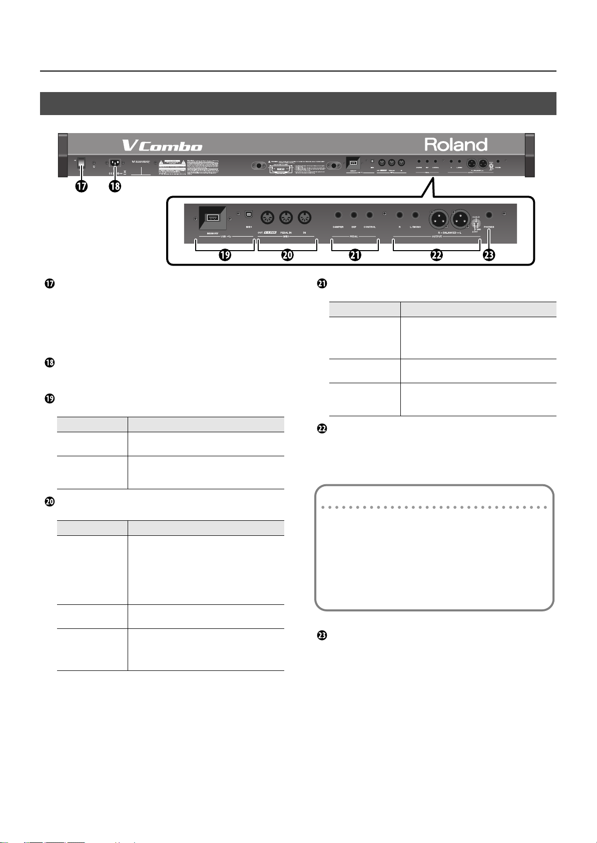
Rear Panel
fig.VR-700Rear.eps
Names of Things and What They Do
[POWER] switch
Turns the power on/off (p. 19).
* If you need to turn off the power completely, first turn off the
[POWER] switch, then unplug the power cord from the power outlet.
Refer to “Power Supply” (p. 6).
AC IN (AC inlet)
Connect the included power cord here (p. 18).
USB connectors
Connector
USB MEMORY
connector
USB MIDI connector
Function
Connect USB memory (sold separately) here (p.
22).
You can use a USB cable (sold separately) to
connect this to your computer so that MIDI
messages can be transmitted and received (p. 67).
MIDI connectors
Connector
MIDI OUT/V-LINK
connector
MIDI PEDAL IN
connector
MIDI IN connector
Function
You can use a MIDI cable (sold separately) to
connect this to a MIDI sound module or other MIDI
device, and transmit performance data from the
VR-700 to that device (p. 65).
If you connect this to a V-LINK compatible video
device, your performance on the VR-700 can
control the video device (p. 64).
You can connect a pedal keyboard here, and
perform using the pedals (p. 20).
You can use a MIDI cable (sold separately) to
connect a MIDI keyboard or other MIDI device
here, and use that MIDI device to play the VR-700
(p. 65).
PEDAL connectors
Connector
DAMPER PEDAL
connector
EXP PEDAL
connector
CONTROL PEDAL
connector
Function
Connect a damper pedal here (p. 20).
Even after you take your fingers off the keyboard,
notes will be sustained as long as you hold down
the pedal.
Connect an expression pedal here. You can use
this pedal to adjust the volume (p. 20).
Connect an expression pedal or damper pedal
here (p. 20). You can use this pedal to control
various functions of the VR-700 (p. 55).
OUTPUT connectors
These are stereo output connectors for the audio signal. The same
signal is output from the XLR connectors (L, R) and from the phone
jacks (L/MONO, R).
About the phone jacks
If you connect a cable only to the L/MONO jacks of the phone
jacks, the sound of the left and right channels will be mixed
and output in monaural.
* The stereo signal will be output from the XLR connectors.
* We recommend that you use stereo output. If you use
monaural output, the quality and character of the sound may
be affected, but this does not indicate a malfunction.
PHONES jack
Connect headphones here (p. 21).
Even if headphones are connected, the audio signal will still be
output from the OUTPUT connectors.
17
Page 18
Getting Ready
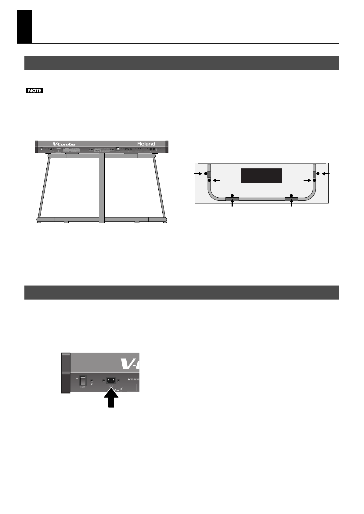
Placing the VR-700 on the KS-G8 Stand
If you place the VR-700 on a stand, you must use the KS-G8 (sold separately).
• When placing the VR-700 on the stand, be careful not to pinch your fingers between the instrument and the stand.
• When lifting the VR-700 onto the stand, make sure to enlist the help of at least one other person.
• Using the VR-700 with any other stand may produce an unstable situation, possibly causing the instrument to fall or overturn, and
resulting in injury or damage.
• For details on how to assemble the stand, refer to the owner’s manual that accompanied the stand.
fig.VKvsKS-G8.eps
Front (keyboard) side
A
Top view
B
C
Rear panel side
Place the VR-700 in the position shown in the illustration.
1.
• Position rubber feet “A” on the outside of the stand’s rubber pads.
• Position rubber feet “B” directly above the stand’s arms.
• Position rubber feet “C” so that they contact the inside of the stand’s rubber pads.
* Make sure that the VR-700’s six rubber feet (A–C) are not resting on the stand’s rubber pads.
Connecting the Power Cord
1.
Before you begin making connections, confirm the following.
• Is the volume level of the VR-700 or connected amp turned all the way down?
• Is the power to the VR-700 or connected amp turned off?
Connect the supplied power cord to the AC Inlet of the VR-700, and plug the other end into an AC outlet.
2.
fig.ConnectPowerCoad.eps
A
B
C
18
Rear panel
Page 19
Turning the Power On/Off
Getting Ready
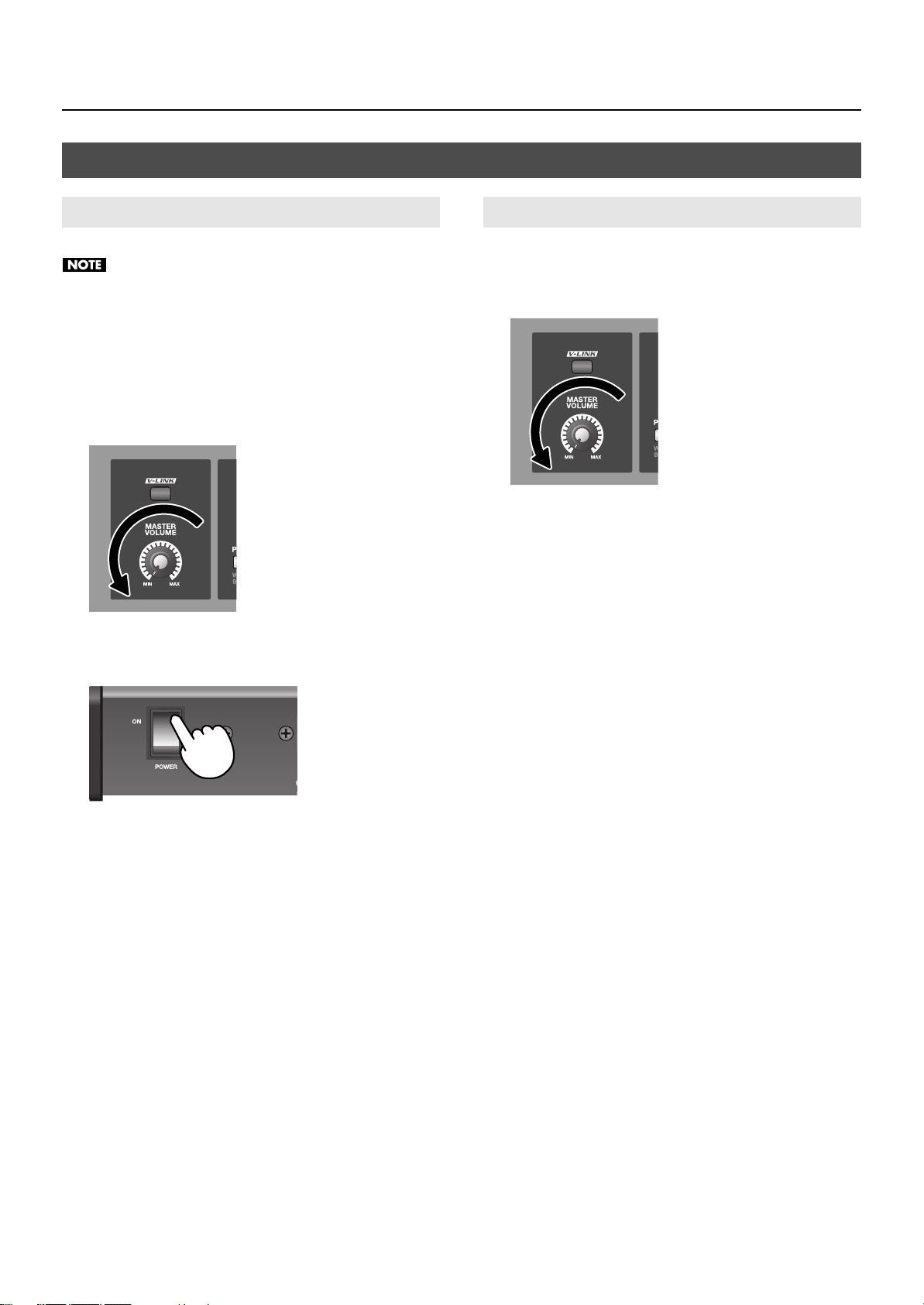
Turning the Power On
Once the connections have been completed, turn on power to
your various devices in the order specified. By turning on
devices in the wrong order, you risk causing malfunction and/
or damage to speakers and other devices.
1.
Before you turn on the power, make sure that the
[VOLUME] knob is turned all the way down.
Also minimize the volume of any connected external audio
equipment.
fig.VolMin.eps
To turn the power on, press the upper part of the
2.
[POWER] switch located on the VR-700’s rear panel.
fig.P-On.eps
Turning the Power Off
1.
Turn the [VOLUME] knob to the minimum position
before you turn off the power.
Also minimize the volume of any connected external equipment.
fig.VolMin.eps
2.
Switch off the power to any connected external
equipment.
3.
To turn the power off, press the lower part of the
[POWER] switch located on the VR-700’s rear panel.
* If you need to turn off the power completely, first turn off the
POWER switch, then unplug the power cord from the power outlet.
Refer to “Power Supply” (p. 6).
The power will turn on, and the display will light up.
* Minimize the volume before you turn on the power. Even if the
volume is minimized, you may hear sound when turning on the
power, but this does not indicate a malfunction.
* Due to a circuitry-protection feature, this unit requires a few
moments after it has been powered up before it is ready for normal
operation.
* If the power is turned off while a Factory Reset is being executed (p.
26), the internal data will be lost, and it may take some time to start
up the next time you switch on the VR-700’s power.
3.
Switch on the power to any external equipment that is
connected.
Adjust the volume of any external equipment that is
4.
connected.
Adjust the VR-700’s volume to an appropriate level.
5.
19
Page 20
Getting Ready
MIDI cable
To MIDI OUT connector
PK-7A
PK-25A
To MIDI PEDAL IN connector
Damper pedal
Expression pedal
Footswitch
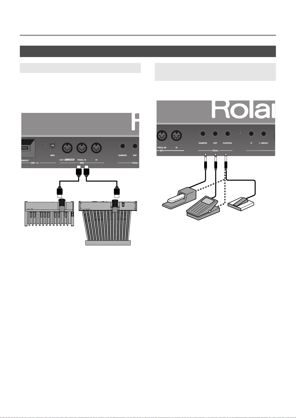
Connecting Pedals
Connecting a Pedal Keyboard
Connect your pedal keyboard (PK-25A or PK-7A; sold separately) to
the MIDI PEDAL IN connector on the rear panel.
* When making connections, be sure to refer to the PK-25A or PK-7A
owner’s manual as well.
* There’s no need to set the MIDI channel for the PK-25A and PK-7A.
fig.ConnectPedalKey.eps
Connecting an Expression Pedal and Damper Pedal
* When making connections, please refer also to the owner’s manual
for the pedals you’re using.
fig.ConnectPedals.eps
1.
2.
3.
* For details on the functions that can be controlled by a foot switch
* There’s no need to make a connection between the EXPRESSION
Make sure that the VR-700 and the pedal you’ll be
connecting are turned off.
Use a MIDI cable (sold separately) to connect the MIDI
OUT connector of the PK-25A or PK-7A to the VR-700’s
MIDI PEDAL IN connector. (The PK OUT connector is not
used.)
If desired, connect the FOOT SW OUT connector of the
PK-25A or PK-7A to the VR-700’s CONTROL PEDAL
connector.
connected to the VR-700’s CONTROL connector, refer to “Functions
that can be assigned to the control pedal” (p. 55).
OUT connector of the PK-25A or PK-7A and the VR-700.
Make sure that the VR-700’s power is turned off.
1.
Connect your damper pedal to the DAMPER PEDAL
2.
connector on the rear panel.
Connect your expression pedal to the EXP PEDAL
3.
connector on the rear panel.
Connect your damper pedal, expression pedal, or foot
4.
switch to the CONTROL PEDAL connector on the rear
panel.
* An expression pedal, damper pedal, and foot switch are not
included. For details on the types of pedals that can be connected to
the VR-700, refer to “Specifications” (p. 80). If you want to purchase
these items, please contact the dealer where you purchased the
VR-700.
* Use only the specified expression pedal (EV-5 or EV-7; sold
separately). By connecting any other expression pedal, you risk
causing malfunction and/or damage to the unit.
20
Page 21
Connecting Playback Equipment
Mixer, etc.
Power amp/speaker
Powered speaker
Headphones
fig.ConnectPA.eps
Getting Ready
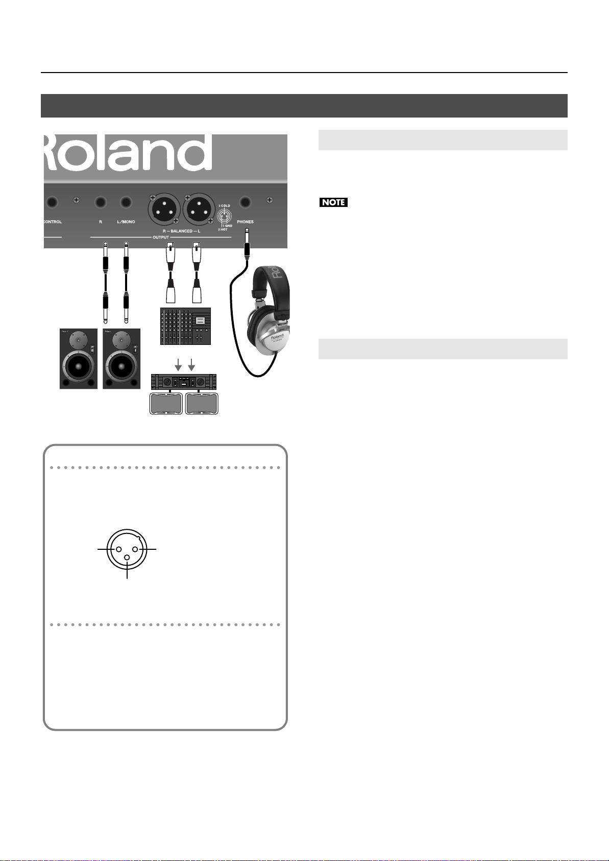
Connecting an Amp and Speakers
1.
Make sure that both the VR-700 and the equipment you
intend to connect are switched off.
To prevent malfunction and/or damage to speakers or other
devices, always turn down the volume, and turn off the power
on all devices before making any connections.
2.
Use audio cables to connect the VR-700’s rear panel
OUTPUT connectors to your playback equipment
(amplified speakers, mixer, etc.).
* Audio cables are not included. If you want to purchase these items,
please contact the dealer where you purchased the VR-700.
Connecting Headphones
About the XLR connector OUTPUT connectors
The XLR connectors are wired as shown in the illustration.
Before you make connections, check the wiring of the
equipment you intend to connect.
fig.XLRJack.eps
1: GND 2: HOT
3: COLD
About the 1/4” phone jack OUTPUT connectors
If you connect a cable only to the L/MONO jack of the phone
jacks, the sound of the left and right channels will be mixed
and output in monaural.
* The stereo signal will be output from the XLR connectors.
* We recommend that you use stereo output. If you use
monaural output, the quality and character of the sound may
be affected, but this does not indicate a malfunction.
Connect your headphones to the PHONES jack on the
1.
VR-700’s rear panel.
* Use headphones that have a 1/4” stereo plug.
21
Page 22
Getting Ready
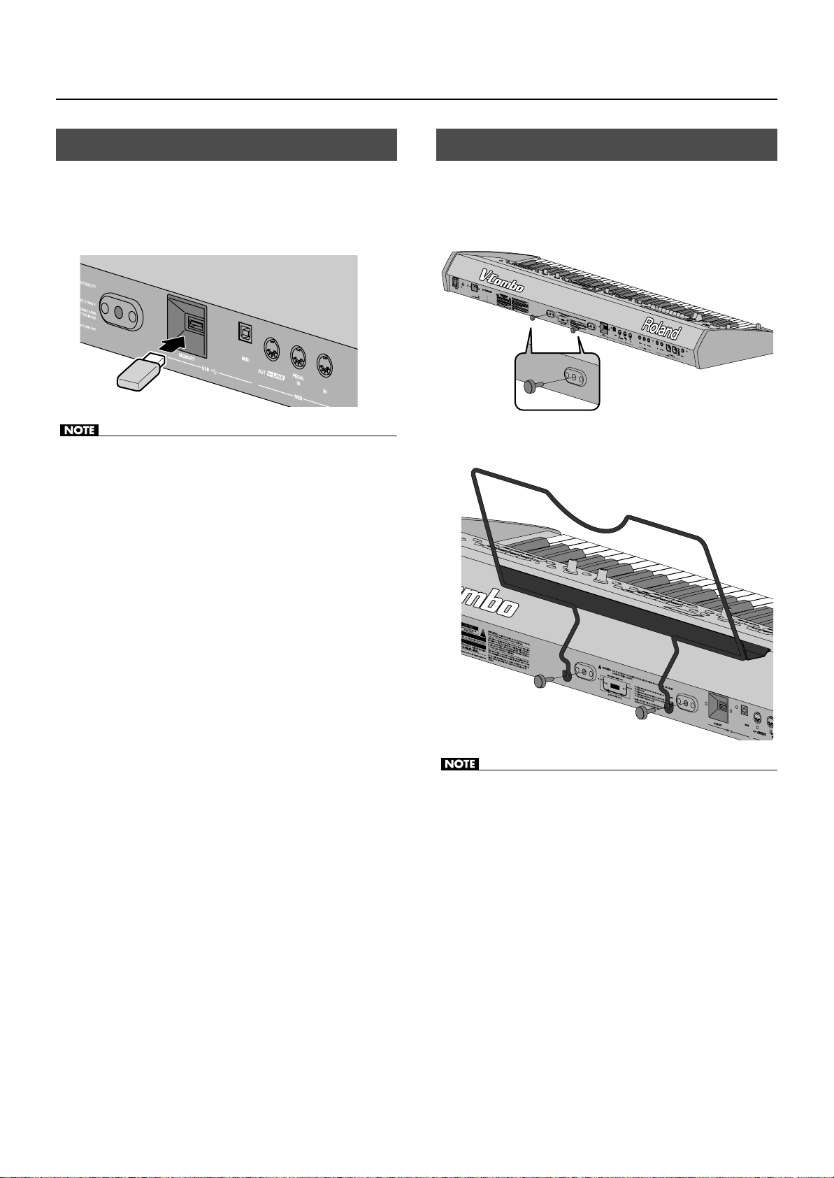
Connecting USB Memory
Make sure that the VR-700’s power is switched off.
1.
Connect your USB memory to the VR-700’s rear panel
2.
USB MEMORY connector.
fig.ConnectUSBmem.eps
• Never insert or remove a USB memory device while this unit’s power
is on. Doing so may corrupt the unit’s data or the data on the USB
memory.
• Carefully insert the USB memory all the way in—until it is firmly in
place.
Attaching the Music Rest
Here’s how to attach the included music rest.
Remove the two music rest fastening screws from the
1.
rear panel.
fig.MusicrestRemove.eps
2.
Tighten the two screws to fasten the music rest in place.
fig.MusicrestAttach.eps
• If you’re using new USB memory, you must first initialize (format) it
on the VR-700, refer to “Formatting USB Memory” (p. 62).
• For details on USB memory device that can be used with the VR-700,
refer to “Specifications” (p. 80). If you want to purchase USB
memory, please contact the retailer from whom you purchased the
VR-700.
• When attaching the music rest, support it securely with your hand
so that it does not fall.
• Be careful not to pinch your hand or fingers when attaching the
music rest.
• Use only the included screws.
• To detach the music rest, support it with your hand and slowly
remove the screws. After detaching the music rest, firmly tighten
the fastening screws.
• The music rest fastening screws you remove must be kept out of the
reach of small children so that they will not be swallowed
accidentally.
22
Page 23
Getting Ready
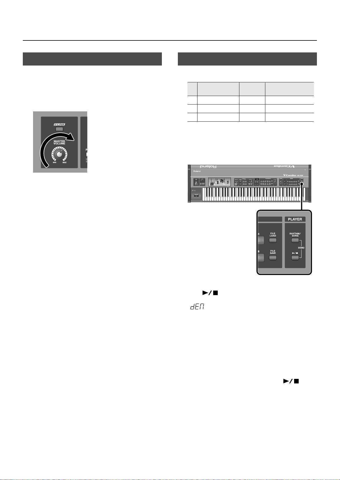
Adjusting the Volume
Use the [VOLUME] knob to adjust the volume.
1.
Turning the knob toward the right will increase the volume, and
turning it toward the left will decrease the volume.
You’ll also need to make appropriate volume adjustments on the
connected equipment.
fig.VolAdj.eps
Listening to the Demo Songs
The VR-700 contains 3 demo songs.
No.
Song Title
1
Desert Stroll Mano Hanes © 2010 Roland Corporation
2 The Odd Mistress Kiyomi Otaka © 2010 Roland Corporation
3 7th Dance on a Sun Ray Ralf Schink © 2010 Roland Corporation
* All rights reserved. Unauthorized use of this material for purposes
other than private, personal enjoyment is a violation of applicable
laws.
fig.demo-play.eps
Composer/
Performer
Copyright
1.
Simultaneously press the [RHYTHM/SONG] button and
[
the
• The VR-700 will enter Demo mode, and the display will indicate
• The FAVORITE [1]–[3] buttons will blink.
• In Demo mode, you can’t edit the organ sound, choose ensemble
sounds, or perform.
The blinking FAVORITE [1]–[3] buttons correspond to the
2.
] (Play/Stop) button.
.
four demo songs. When you press one of the buttons, the
corresponding demo song will begin playing.
When the demo song has finished playing, the next demo song will
play.
3.
To stop demo song playback, press the [
(Play/Stop) button.
4.
To exit Demo mode, press the [DISPLAY/EXIT] button.
* No data for the music that is played will be output from the MIDI
OUT connector and USB MIDI connector.
]
23
Page 24
Getting Ready
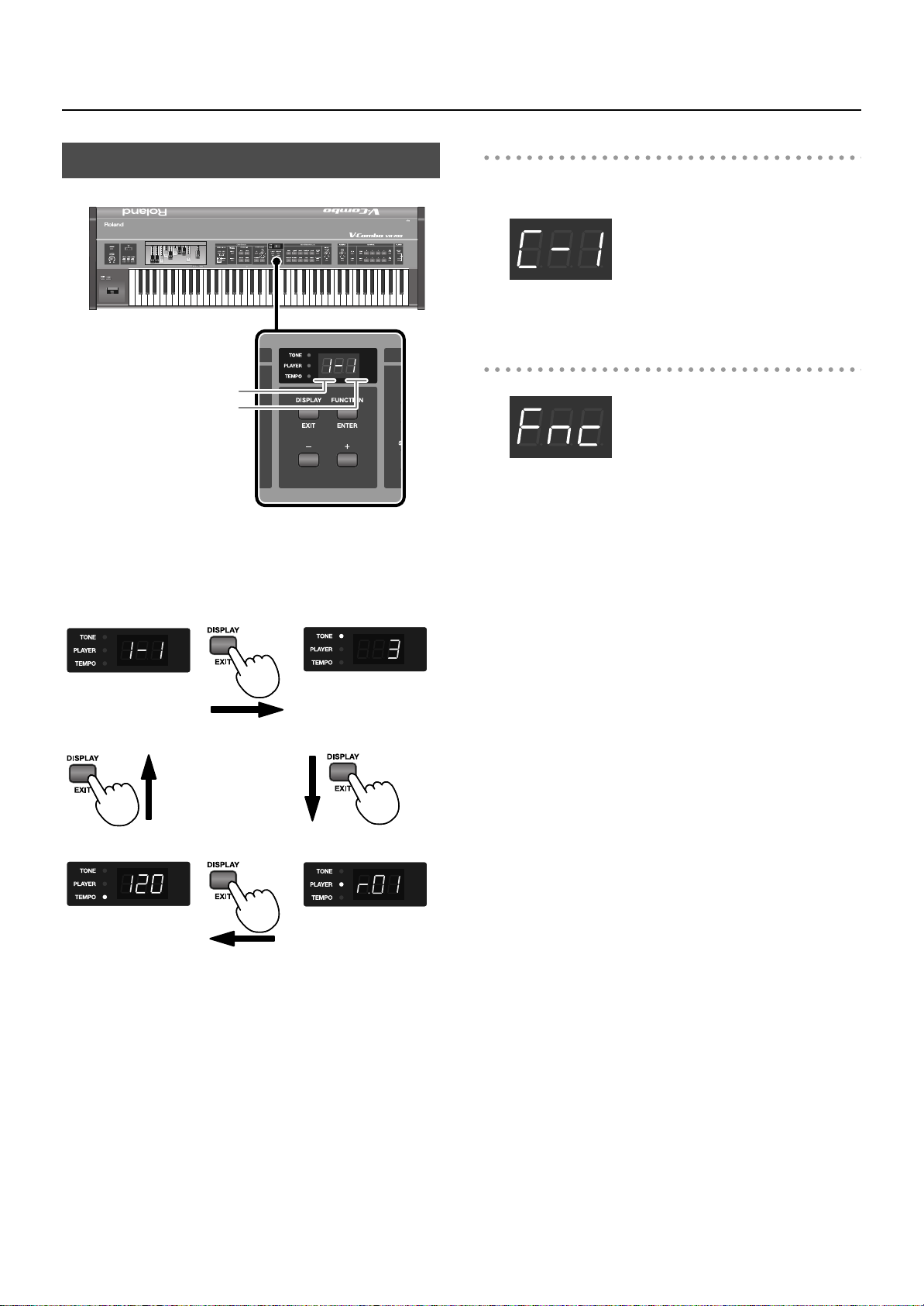
Indications in the Display
fig.paneldisp.eps
Indications when editing settings
When you’re changing the reverb or chorus type, the display will
indicate the respective type.
fig.disp-type01.eps
From this state, you can press the [DISPLAY/EXIT] button to return to
the previous display.
Indications in Function mode
Bank number
Favorite number
When you switch on the VR-700’s power, the current favorite
number is shown in the display.
Pressing the [DISPLAY/EXIT] button cycles you through the
following choices for what is displayed.
fig.disp-norm01.eps
Normal state
(indicates the favorite
number)
fig.arrow-top.eps
fig.arrow-right.eps
fig.disp-tone01.eps
Tone number of the
ensemble sound
fig.arrow-bottom.eps
fig.disp-func01.eps
When you press the [FUNCTION/ENTER] button, the VR-700 will
enter Function mode. In Function mode you can specify Favorites
and make detailed settings for the VR-700 (p. 51).
fig.disp-tempo01.eps
Tempo of the internal
rhythm or song
(p. 50)
24
fig.arrow-reft.eps
fig.disp-player01.eps
Player function’s rhythm
and song selection
(p. 49)
Page 25
Getting Ready
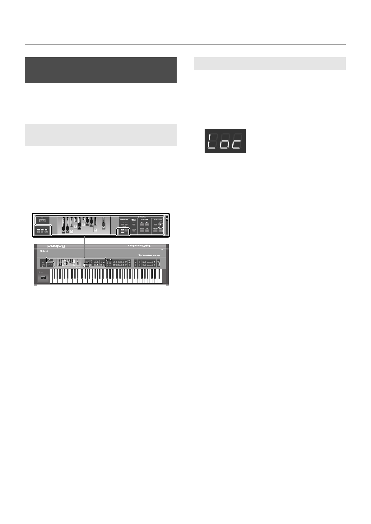
Disabling Panel Operations (Lock Function)
Lock function is a function that disables operation of the panel’s
buttons, and knobs. By locking the panel, you can prevent settings
from being inadvertently changed while you’re on stage.
Controls That can be Operated Even While Locked
The following top panel controls can be operated even if the Lock
function is turned on. This allows you to control the sound of the
organ in real time even when the Lock function is on.
• Harmonic bars (see illustration)
• Some buttons and knobs of the organ section (see illustration)
• D Beam controller
• Organ control/Bender lever
Turning the Lock Function On/Off
1.
Hold down the HARMONIC BAR [LOWER] button and
press the PLAYER [RHYTHM/SONG] button.
When the panel has been locked, the VR-700 will be in the following
state.
• Song playback will stop.
• The following will be shown in the display.
fig.disp-func01.eps
To turn off the Lock function, press the [DISPLAY/EXIT]
2.
button.
Alternatively, you can turn off the Lock function by repeating the
action of step 1.
25
Page 26
Getting Ready
Restoring the Factory Settings (Factory Reset)
When you execute the Factory Reset operation, all Favorite settings
in the VR-700 and the values of the system parameters that can be
edited in Function mode will all be returned to their factory-set
condition.
If you want to keep the Favorite settings that are stored in the
VR-700 and the values of the system parameters, back them up
to USB memory as described in “Backing up Favorites to USB
Memory” (p. 48).
1.
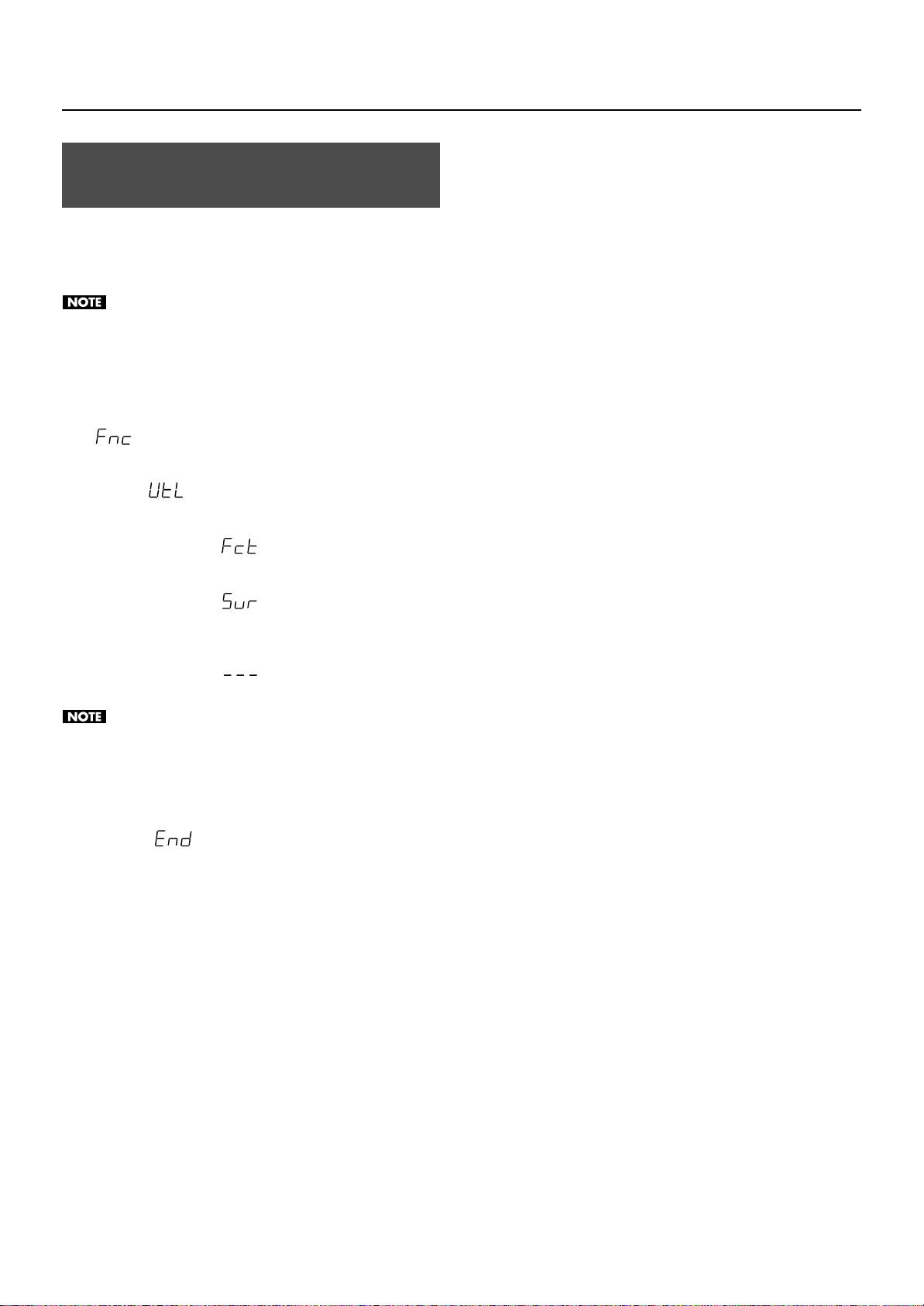
Press the [FUNCTION/ENTER] button.
The VR-700 will enter Function mode, and the display will indicate
.
Use the [–] button or [+] button to make the display
2.
indicate
Press the [STRINGS] button.
3.
The display will indicate
.
.
4.
Press the [FUNCTION/ENTER] button.
The display will indicate
5.
To execute the Factory Reset, press the [FUNCTION/
ENTER] button.
The display will indicate
executed.
Never turn off the VR-700’s power while the Factory Reset is
being executed.
* If you decide not to execute the Factory Reset, press the [DISPLAY/
EXIT] button.
When the Factory Reset is completed, the display will
6.
indicates
Turn the VR-700’s power off, then on again.
.
.
while the Factory Reset is being
26
Page 27
Playing the VR-700
About the VR-700’s Parts
The VR-700 has three parts: Upper part, Lower part, and Pedal part.
You can play a different sound in each of the three parts.
Upper Part
When using an external MIDI keyboard
If you connect an external MIDI keyboard to the MIDI IN connector
on the rear panel, you can use your external MIDI keyboard to play
the upper part while using the VR-700’s keyboard to play the lower
part (or vice versa).
fig.part-uploWmidi.eps
External MIDI keyboard
When the Split function (p. 34) is off, the Upper part will sound when
you play the keyboard.
fig.part-upper.eps
VR-700
Upper part
Lower Part
If you turn on the Split function, the higher range of the keyboard
will play the upper part and the lower range will play the lower part.
fig.btn-split.eps
MIDI
VR-700
Lower part
• If you’re using an external MIDI keyboard, change the Function
mode setting Sub Keyboard Function to upper (or lower). For more
about the Sub Keyboard Function setting, refer to “Various Settings
(Function mode)” (p. 51) and “Sub Keyboard Function” (p. 57).
• For details on connecting your external MIDI keyboard, refer to
“Connecting an External MIDI Keyboard” (p. 66).
Upper part
fig.part-uplo.eps
VR-700
Lower part
For more about the Split function, refer to “Playing the Sounds
of Two Parts on the Keyboard (Split)” (p. 34).
Upper part
27
Page 28

Playing the VR-700
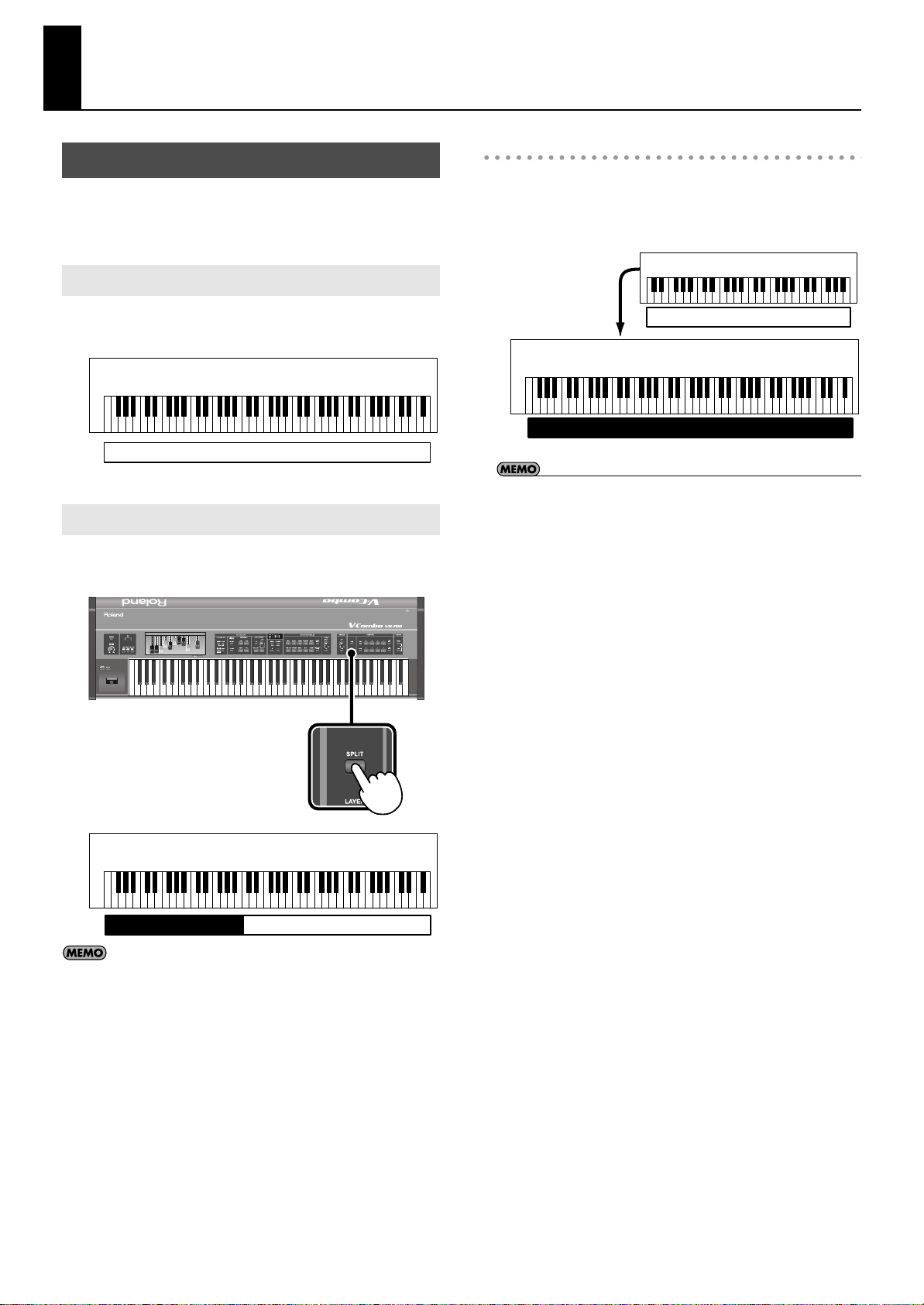
Pedal Part
To turn on the Split function, hold down the [LOWER] and [UPPER]
buttons, and press the [SPLIT] button; the higher range of the
keyboard will play the upper part, and the lower range of the
keyboard will play the pedal part.
fig.btn-splitpedal.eps
fig.part-uppdl.eps
VR-700
Pedal part
If you hold down the [LOWER] button and press the [SPLIT]
button, the higher range of the keyboard will play the upper
part, and the lower range of the keyboard will play the lower
part.
When using a pedal keyboard
If you connect a pedal keyboard to the rear panel MIDI PEDAL IN
connector, you can use your pedal keyboard to play the pedal part.
fig.part-pedal.eps
VR-700
Upper part
Organ Sounds and Ensemble Sounds
Organ sounds
You can play different organ sounds from each of the VR-700’s three
parts.
The upper, lower, and pedal parts correspond to the upper organ,
lower organ, and pedal organ sounds, respectively.
fig.part-3organ.eps
VR-700
Lower organ
Pedal keyboard
Pedal organ
Ensemble sounds
In addition to organ sounds, you can also play ensemble sounds (p.
46). The VR-700 contains various ensemble sounds. You can play
two ensemble sounds simultaneously.
The two ensemble sounds can be assigned to any desired parts.
The illustration below is a conceptual diagram of sounds assigned to
the upper part and lower part.
fig.part-3organ2ens.eps
VR-700
Ensemble sound 1 Ensemble sound 2
Upper organ
Upper organLower organ
28
Upper part
MIDI
Pedal keyboard
Pedal part
For details on connecting your pedal keyboard, refer to
“Connecting a Pedal Keyboard” (p. 20).
Pedal keyboard
Pedal organ
Page 29

Playing Organ Sounds and Ensemble Sounds Together (Layer)
Layering Ensemble Sounds
You can assign an ensemble sound to a desired part, and play it
together with an organ sound.
fig.layer01.eps
Playing the VR-700
1. Changing the ensemble sound’s variation
fig.ens-assign02.eps
When the TONE indicator is lit, you can use the [+] button or [–]
button to select variations of the ensemble sound.
1.
Press the [LAYER] button to turn it on; layering is now
enabled.
2.
Press one of the ensemble sound buttons.
The ensemble sound will be assigned to the upper part; when you
play the keyboard, you’ll hear the upper organ and the ensemble
sound together.
fig.Layer-assign01.eps
Upper organ
Ensemble sound
2. Adjusting the ensemble sound’s volume
Use the [ENSEMBLE VOLUME] bar to adjust the volume of the
ensemble sound.
fig.ens-assign03.eps
• The display will indicate the ensemble sound’s tone number (p. 24).
• If you press an ensemble sound button without pressing the
[LAYER] button, only the ensemble sound will be heard (p. 33).
29
Page 30

Playing the VR-700
Lower organ Upper organ
Ensemble sound
Ensemble sound 1
Ensemble sound 2
Upper organ
3. Assigning an ensemble sound to the lower part
To assign the ensemble sound to the Lower part, press the [TO
LOWER/PEDAL] button.
The [TO LOWER/PEDAL] button will light and “Lo” will be shown in
the display.
At the same time, Split (p. 34) will turn on, allowing you to play the
upper organ sound in the upper part.
fig.ens-assign04.eps
Layering Two Ensemble Sounds
1.
Press the [LAYER] button to turn it on; layering is now
enabled.
fig.layer01.eps
While holding down an ensemble sound button, press
2.
the button of another ensemble sound.
• While you hold down the two sound buttons, the display will
indicate the volume balance between the two ensemble sounds (p.
31).
• When you play the upper part, you’ll hear the upper organ and the
two ensemble sounds together.
fig.ens-assign11.eps
4. Assigning an ensemble sound to the pedal part
To assign the ensemble sound to the Pedal part, hold down the [TO
LOWER/PEDAL] button while you press the [–] button.
The [TO LOWER/PEDAL] button will light and “Pd” will be shown in
the display.
When you press the [SPLIT], [LOWER], and [UPPER] buttons
simultaneously, the Split function will turn on; the higher range
of the keyboard will play the upper part, and the lower range of
the keyboard will play the pedal part (p. 28).
30
Page 31

Playing the VR-700
Volume of
ensemble sound 1
Volume of
ensemble sound 2
The ensemble sound button you pressed first will light red, and the
ensemble sound button you pressed second will light green.
The ensemble sound whose button is lit red is called “ensemble
sound 1,” and the ensemble sound whose button is lit green is
called “ensemble sound 2.”
fig.ens-assign12.eps
Lights red:
Ensemble sound 1
Lights green:
Ensemble sound 2
1. Changing the ensemble sound’s variation
2. Adjusting the volume balance of the ensemble
sounds
While holding down the buttons of ensemble sound 1 and
ensemble sound 2, press the [+] button or [–] button to change the
volume balance of the ensemble sounds.
fig.ens-assign15.eps
For ensemble sound 1
In the same way as when using only one ensemble sound (p. 46), the
variation of ensemble sound 1 can be changed by using the [+]
button or [–] button when the TONE indicator is lit.
For ensemble sound 2
To change the variation of ensemble sound 2, hold down the button
of ensemble sound 2, and use the [+] button or [–] button.
fig.ens-assign13.eps
31
Page 32

Playing the VR-700
Lights green:
Ensemble sound 2
3. Assigning an ensemble sound to the lower part
For ensemble sound 1
In the same way as when using just one ensemble sound (p. 30),
press the [TO LOWER/PEDAL] button; the lower part will switch to
ensemble sound 1, and the [TO LOWER/PEDAL] button will light.
For ensemble sound 2
Hold down the button of ensemble sound 2 and press the [TO
LOWER/PEDAL] button; the lower part will switch to ensemble
sound 2.
fig.ens-assign16.eps
4. Assigning an ensemble sound to the pedal part
For ensemble sound 1
In the same way as when using just one ensemble sound (p. 30), the
ensemble sound is assigned to the Pedal part by holding down the
[TO LOWER/PEDAL] button and pressing the [–] button.
The [TO LOWER/PEDAL] button will light and “Pd” will be shown in
the display.
For ensemble sound 2
To assign the Ensemble 2 sound to the Pedal part, hold down both
the Ensemble 2 button and the [TO LOWER/PEDAL] button while
you press the [–] button.
If you hold down the [LOWER] and [UPPER] buttons and press
the [SPLIT] button, the Split function will turn on, allowing you
to play the upper part in the higher range of the keyboard and
the pedal part in the lower range of the keyboard (p. 28).
The [TO LOWER/PEDAL] button indicates the status of
ensemble sound 1. If you hold down the button of ensemble
sound 2, the [TO LOWER/PEDAL] button will instead indicate
the status of ensemble sound 2.
32
Page 33

Playing the VR-700
Playing Organ Sounds or Ensemble Sounds Individually
Playing Only an Ensemble Sound
Turn off the Split function.
1.
If the Split function is on, press the [SPLIT] button so it’s turned off.
2.
Press the ensemble sound button.
The ensemble sound will be assigned to the upper part.
The organ sound will be muted.
fig.Single01.eps
Playing Only the Organ Sound
1.
Press the [ORGAN ON] button.
The [ORGAN ON] button will light, and all parts will play the organ
sound.
The ensemble sound selection will be cleared. If you want to
play ensemble sounds again, you’ll need to re-select the
ensemble sound.
Changing a layered part to play only the organ
sound
1.
Press the [LAYER] button to turn it off
2.
Press the [ORGAN ON] button.
The [ORGAN ON] button will light, and all parts will play the organ
sound.
The ensemble sound selection will be cleared. If you want to
layer ensemble sounds again, enable layering as described in
“Playing Organ Sounds and Ensemble Sounds Together
(Layer)” (p. 29).
• You can switch variations of the ensemble sound, adjust its volume,
and assign it to the lower part or pedal part in the same way as
when Layer is turned on. For details, refer to “Playing Organ Sounds
and Ensemble Sounds Together (Layer)” (p. 29).
• Operation when playing two ensemble sounds is the same as when
Layer is on. For details, refer to “Layering Two Ensemble Sounds” (p.
30).
Switching a layered part to only the ensemble
sound
Press the [LAYER] button to turn it off.
1.
The [ORGAN ON] button will go out, and the organ sound will be
muted.
If you’ve layered the organ sound and ensemble sound for
more than one part, the organ sound will be muted for both
parts. It’s not possible to mute the organ sound for just one of
the parts.
33
Page 34

Playing the VR-700
Upper part
VR-700
Lower part
Playing the Sounds of Two Parts on the Keyboard (Split)
Playing the upper part and lower part
Press the [SPLIT] button; the upper part will be assigned to the
upper zone of the keyboard, and the lower part to the lower zone of
the keyboard.
fig.btn-split.eps
Playing the upper part and pedal part
To turn on the Split function, hold down the [LOWER] and [UPPER]
buttons, and press the [SPLIT] button; the higher range of the
keyboard will play the upper part, and the lower range of the
keyboard will play the pedal part.
fig.btn-splitpedal.eps
fig.part-uppdl.eps
VR-700
fig.part-uplo.eps
Split will automatically be turned on when you assign an
ensemble sound to the lower part (p. 30).
Pedal part
If you hold down the [LOWER] button and press the [SPLIT]
button, the higher range of the keyboard will play the upper
part, and the lower range of the keyboard will play the lower
part.
Upper part
34
Page 35

Boundary Between Upper and Lower Parts
How the Split Point Is Shown
When indicating the key that is the Split Point, the display
shows the note name followed by a number that signifies the
octave.
fig.disp-split.eps
Display Note name Display Note name
C F
C G
D A
E A
E B
F B
(Split Point)
The VR-700 has a printed symbol to indicate the boundary (the split
point) between the upper part and lower part.
fig.splitpt.eps
Playing the VR-700
OctaveNote name
When you press the [SPLIT] button to turn Split on, the display will
indicate the split point.
The split point is indicated as the highest key of the lower part
(or the pedal part.)
Changing the split point
You can use either of the following two ways to change the split
point.
• Hold down the [SPLIT] button and press the key of the desired split
point.
• Hold down the [SPLIT] button and use the [+] button or [–] button to
specify the desired split point.
35
Page 36

Playing the VR-700
Using the D Beam Controller to Modify the Sound
By moving your hand above the D Beam controller you can apply a
variety of effects to the VR-700’s sound.
fig.Dbeam01.eps
Press a button to select the D Beam effect.
1.
The button will light, and the D Beam effect will be selected.
Press the lit button a number of times until its light goes out; the D
beam will be turned off.
While you play, place your hand above the D Beam
2.
controller and slowly move it up and down.
The effect will be applied when you move your hand near the D
Beam controller, and will return to its original state when you move
your hand away. The button will blink when the D Beam controller is
responding.
The usable range of the D Beam controller
fig.splitpt.eps
D Beam Effects
Effects applied to ensemble sounds
When you press a button, it will light red, and the D Beam effect will
be applied to ensemble sounds.
* For details on how to assign an ensemble sound, refer to “Playing
Organ Sounds and Ensemble Sounds Together (Layer)” (p. 29).
Button (lights red)
[PITCH] button
[FILTER] button
[VOLUME] button
* The D Beam effect will apply to all ensemble sounds.
Effects applied to organ sounds
When you press a button twice, it will light green, and the D Beam
effect will be applied to organ sounds.
Button (lights green)
[WHEEL BRAKE] button
[RING MOD] button
[SPRING SHOCK] button
Effect
The pitch will fall as you move your hand
closer to the D Beam controller.
The maximum amount of pitch change
depends on the Function mode “Bend
Range” setting (p. 54).
The high-frequency range will be diminished
as you move your hand closer to the D Beam
controller, producing a more muffled sound.
The volume will decrease as you move your
hand closer to the D Beam controller.
Effect
The Wheel Brake (p. 37) will be applied as you
move your hand closer to the D Beam
controller. The Wheel Brake will turn off
when you move your hand away from the D
Beam controller.
The Ring Modulator (p. 37) will be applied
when you move your hand close to the D
Beam controller. The closer your hand is to
the D Beam controller, the stronger the Ring
Modulator will be.
A spring reverb shock sound (p. 37) will be
heard when you move your hand close to the
D Beam controller.
The diagram shows the usable range of the D Beam controller.
Moving your hand outside this range will produce no effect.
* The sensitivity of the D Beam controller will change depending
on the amount of light in the vicinity of the unit. If it does not
function as you expect, adjust the sensitivity as appropriate for
the brightness of your location (p. 54).
36
* The volume of the spring reverb shock sound can be adjusted by
the REVERB [LEVEL] knob. The spring shock will be more effective if
you choose “SPRING” as the reverb type (p. 44).
Page 37

What is the Wheel Brake?
This simulates the way in which the tonewheels stop rotating
when you switch off the power on a tonewheel organ.
Since the amplifier of a tonewheel organ consisted of analog
circuits using vacuum tubes, it would continue to produce
sound for a short time even after the power was turned off.
However, since the organ’s tonewheels would start slowing
down as soon as the power was turned off, this would make
the pitch drop. The technique of stopping the tonewheels was
sometimes used on tonewheel organs. A skilled performer
could use this effect within their music.
What is a Ring Modulator?
This simulates a circuit that produces an unpitched metallic
sound by varying the frequency of the ring modulator’s
internal oscillator.
In hard rock of the past, some organ players applied aggressive
effects such as a ring modulator to their organ in order to
compete with the aggressive playing of the electric guitarist.
A ring modulator is an effect that generates complex overtones
that are not found in the original sound. These complex
overtones create a metallic-sounding resonance.
The word “ring” comes from the ring-shaped circuit that is
formed when a ring modulator is constructed using analog
components.
Playing the VR-700
What is a Spring Reverb?
In the days when analog circuits were used, some reverb units
produced their reverb effects by using a spring. This was the
Spring Reverb. When physical impact is applied to a spring
reverb unit, the springs bounce against each other, producing
a distinctive clashing sound. Some performers used this sound
intentionally.
37
Page 38

Creating Organ Sounds
Time
Time
8’ volume: 8
Time
4’ volume: 5
About Virtual Tonewheel Sound Generators
Tonewheel organs are a type of organ that produce their sound by
means of toothed wheels called “tonewheels.”
Tonewheel organs contain numerous tonewheels, with each wheel
corresponding to a key. The tonewheels are rotated by a motor.
When a key is pressed, a pickup detects the motion of that wheel’s
teeth as they rotate past a pickup, and converts this motion into
sound. Because of this method of producing sound, tonewheel
organs are able to produce sounds with a rapid (strong) attack, and
came to be used in a wide range of musical styles.
The VR-700 contains a “virtual tonewheel sound generator,” which
uses digital technology to faithfully simulate the sound-generating
methods of a tonewheel organ. In the same way as a traditional
tonewheel organ, the VR-700 lets you use harmonic bars to create
the basic sound of the organ.
It also uses digital technology to faithfully simulate various
distinctive characteristics of the tonewheel organ, and allows you to
freely vary these.
Ordinarily, the tone wheels revolve at a fixed speed. However, some
performers have been known to use a technique whereby they raise
the pitch by pushing the start switch while they’re performing,
which increases the speed of the tone wheels’ revolution. You can
re-create this effect by turning on the [ORGAN CONTROL] button,
then pushing the bend lever away from yourself.
In addition, it digitally recreates the vibrato, chorus, and rotary
speaker sounds that are indispensable to an organ sound, giving
you a great deal of freedom to create the sound you want.
Varying the Sound in Real Time (Harmonic Bars)
The harmonic bars are controllers that create the basic framework of
the organ sound. By sliding the nine bars in or out, you can vary the
organ sound in real time.
fig.H-bar.eps
An overtone of a different pitch is assigned to each harmonic bar,
and you can create the organ sound by combining these overtones.
If you push a harmonic bar inward until none of the numerals
printed on it are visible, the overtone corresponding to that
harmonic bar will not be heard. If the harmonic bar is pulled
outward all the way, its volume will be at the maximum.
fig.H-bar-Logic.eps
38
Page 39

Creating Organ Sounds
16’ 8’ 4’ 2’ 1’5 1/3’ 2 2/3’ 1 3/5’ 1 1/3’
one octave
below
5th root 8th 12th 15th 17th 19th 22th
Using the Harmonic Bars to Create Sounds
1.
Press either the HARMONIC BAR [UPPER] button or the
[LOWER] button to select the part whose sound you want
to create.
fig.pnl-assgn.eps
Part
Upper part
Lower part Press the [Lower] button
Pedal part
“About the VR-700’s Parts” (p. 27)
Operation
Press the [Upper] button
Press the [Upper] button and [Lower]
button simultaneously
Harmonic Bars and Overtones
The numbers (16’, 5-1/3’, etc.) printed on each harmonic bar are the
“footage” (a number of feet). The footage plays an important role in
determining the tonal character. 8’ is the basic footage (pitch); you’ll
be creating the sound around this basic pitch.
If you play the middle ‘C’ note (C4), the harmonic bars will be
sounding the following pitches.
fig.H-bar-Harmonic.eps
There are three colors of harmonic bars. Those that are in octave
multiples of 8’ are white, those that are not octave multiples are
black, and the lower-pitched bars are brown.
2.
Press the [MANUAL] button.
When you press the [MANUAL] button so it’s lit, the organ sound will
reflect the current settings of the harmonic bars.
3.
Move the harmonic bars to modify the sound.
• The sound you create can be saved as a Favorite (p. 47).
• If percussion is turned on, the 1’ sound will not be heard (p. 41).
• For the Pedal part, only the 16’ and 8’ sounds will speak.
• To hear the sound of the lower part, turn Split on, and then use the
left range of the keyboard to play the sound of the lower part (p. 34)
or connect an external MIDI keyboard (p. 66). To hear the sound of
the pedal part, turn Split on, and then use the left range of the
keyboard to play the sound of the pedal part (p. 34) or connect an
external pedal keyboard (p. 20).
39
Page 40

Creating Organ Sounds
What is footage?
This comes from the length of pipes in a pipe organ. On a
pipe organ, the pipes that sound the fundamental pitch of
each key are considered by convention to have a length of
eight feet (8’). A pipe that is half this length will produce a
pitch that is one octave higher, and a pipe that is double this
length will produce a pitch that is one octave lower. Thus, the
sixteen-foot (16’) pipe is one octave lower, and the four-foot
(4’) pipe is one octave higher.
A tonewheel organ’s overtone structure
In certain regions of a tonewheel organ’s keyboard, the
overtones will not correspond to the configuration of the
harmonic bars. In order to prevent unpleasantly high or low
pitches, the high footage is “folded back down” in oneoctave units for the high range, while the low footage is
“folded back up” in one-octave units for the low range. The
VR-700 faithfully reproduces this characteristic of tonewheel
organs.
How the harmonic bars are arranged
If you take a look at how the harmonic bars are arranged,
you’ll notice that the 5-1/3’ footage alone is not located in
the order of its pitch. This is because the 5-1/3’ pitch is not a
multiple of the 8’ pitch, but a multiple (the third harmonic) of
the 16’ pitch. In general, sounds consisting only of overtones
that are integer multiples will sound consonant, while sounds
that contain non-integer multiples will sound muddy. Since
the 5-1/3’ pitch is more easily understood as an overtone of a
16’ fundamental, the 5-1/3’ harmonic bar is placed beside the
16’ harmonic bar.
40
Page 41

Using Percussion to add a Sense of Attack
Volume of the
harmonic bar
Volume
Time
Percussion sound will decay
Percussion
Volume of the harmonic
bars will decreases
Volume
Time
Creating Organ Sounds
Percussion adds a sharply decaying component to the beginning of
the sound, giving the sound more crispness. When you play legato,
percussion is added only to the first note you play. When you play
staccato, percussion is added to each note.
* Percussion can be added only to the upper part’s organ sound.
Percussion cannot be added to the lower part, the pedal part, or to
ensemble sounds.
Button
[SOFT] button
ON OFF
The percussion sound will be decreased, and the harmonic bars will
have their usual volume.
fig.Perc-Soft.eps
fig.pnl-perc.eps
The percussion sound will be at its normal volume, and the sound of
the harmonic bars will be decreased.
fig.Perc-Hard.eps
[SLOW] button
* The volume when percussion is softened can be adjusted by the
Function mode setting “Percussion Soft Level” (p. 52).
The percussion sound will decay more slowly, producing a gentler
attack.
fig.Perc-Slow.eps
Volume
Long decay time
Percussion
* The volume when percussion is normal can be adjusted by the
Function mode setting “Percussion Normal Level” (p. 52).
The percussion sound will decay quickly, producing a sharper attack.
fig.Perc-Fast.eps
Volume
Short decay time
Percussion
Volume of the
harmonic bars
Time
* The percussion decay time can be adjusted by the Function mode
setting “Percussion Slow Time” (p. 52).
[SECOND] button Percussion of the same pitch as the 4’ harmonic bar will be heard Percussion will not sound.
[THIRD] button Percussion of the same pitch as the 2-2/3’ harmonic bar will be heard. Percussion will not sound.
* The percussion decay time can be adjusted by the Function mode
setting “Percussion Fast Time” (p. 52).
Time
• If percussion is on, the 1’ harmonic bar will not sound.
• The [SECOND] button and [THIRD] button cannot be turned on simultaneously.
• If you turn the [SOFT] button off, the organ sound specified by the harmonic bars will decrease. This reproduces the characteristics of a tonewheel
organ. The Function mode setting “Percussion H-Bar Level” lets you specify how much the organ volume will decrease when the [SOFT] button is
turned off (p. 52).
41
Page 42

Creating Organ Sounds
About percussion on a tonewheel organ
The percussion sound on a tonewheel organ does not apply to
all the keys you play. Percussion will apply only to those keys
that are simultaneously pressed from a state of no keys being
pressed.
If you play legato, percussion will apply only to the first note
you play. If you play staccato, percussion will apply to every
note. This is called the “single-trigger algorithm,” and is an
indispensable part of organ performance expression.
On a tonewheel organ, the percussion is created by analog
circuitry. For this reason, the percussion circuit may not have
enough time to recharge if there is only an extremely brief
interval between the releasing of a key to the pressing of the
next key, causing the percussion to sound at a lower volume.
The VR-700 reproduces this characteristic of the circuit’s
recharge time, and provides a Function mode setting
“Percussion Recharge Time” that lets you adjust it (p. 52).
Adding Modulation to the Sound (Vibrato and Chorus)
By pressing the [VIBRATO] button or [CHORUS] button to turn it on,
you can apply vibrato or chorus to the organ sound.
ig.pnl-vibcho.eps
* You can’t apply vibrato and chorus simultaneously. Nor can you
apply vibrato or chorus with differing settings to the upper part,
lower part, and pedal part.
* Vibrato and chorus will not apply to the percussion sound.
Turning on Vibrato or Chorus
1.
Press the [VIBRATO] button or the [CHORUS] button.
The button you pressed will light, and the vibrato or chorus effect
will be applied to the organ sound.
Changing the Vibrato or Chorus Type
The vibrato and chorus effects can each be switched between three
types.
* You can’t switch the vibrato or chorus type when vibrato or chorus
is on.
Verify that vibrato or chorus is off, and press the
1.
[VIBRATO] button or [CHORUS] button.
The display will indicate the current vibrato type (V-1, V-2, V-3) or
chorus type (C-1, C-2, C-3).
2.
Use the [–] button or [+] button to change the vibrato or
chorus type.
The effect will intensify as the vibrato type (V-1, V-2, V-3) or
chorus type (C-1, C-2, C-3) moves to a higher number.
42
Page 43

Adding Rotary Speaker Modulation
Detailed settings for the rotary speaker
In Function mode you can make detailed settings for the rotary
speaker (p. 53).
Speaker volume
You can specify the volumes of the tweeter and the woofer.
• Volume of the tweeter: Rotary Tweeter Level
• Volume of the woofer: Rotary Woofer Level
Rotational speed switching time
You can specify whether the rotational speed will change
slowly or quickly.
The higher the value, the faster the change.
Changing from SLOW to FAST
• Woofer: Rotary Woofer Rise Time
• Tweeter: Rotary Tweeter Rise Time
You can add the modulating sound that is typical of an organ with a
rotary speaker connected.
fig.pnl-rot.eps
The most typical rotary speaker unit contained a high-frequency
speaker (tweeter) and a low-frequency speaker (woofer), each of
which rotated at a different speed. The VR-700 simulates the effect
produced by a rotary speaker.
You can use the buttons in the rotary sound section to control the
operation of the rotary speaker.
Button
[ON] button Turns on the rotary speaker effect.
[SLOW/FAST]
button
[BRAKE] button
You can also use the bender lever (p. 14) or foot pedal to
control the operation of the [SLOW/FAST] button and [BRAKE]
button (p. 55).
Description
Switches the rotational speed of the
rotary speaker.
Press the [SLOW/FAST] button to toggle
between FAST and SLOW.
FAST is selected when the indicator is
blinking rapidly, and SLOW is selected
when the indicator is blinking slowly.
When you turn this on (lit), the rotational
speed of the speaker will slow down and
eventually stop completely.
* The function mode setting “Rotary
Brake Position” lets you specify
whether the speaker will come to rest
at a random angle or at the same angle
each time when the rotation is stopped
completely (p. 52).
Creating Organ Sounds
Changing from FAST to SLOW
• Woofer: Rotary Woofer Rise Time
• Tweeter: Rotary Tweeter Rise Time
Spread
You can specify the amount by which the sound will appear to
be spread to left and right by the rotation of the speaker.
• Woofer: Rotary Woofer Spread
• Tweeter: Rotary Tweeter Spread
Rotational speed
You can specify the speeds of the SLOW and the FAST rotation.
SLOW rotational speed
• Woofer: Rotary Woofer Slow Speed
• Tweeter: Rotary Tweeter Slow Speed
FAST rotational speed
• Woofer: Rotary Woofer Fast Speed
• Tweeter: Rotary Tweeter Fast Speed
Distance between speaker and microphone
The distance between the speaker and the microphone will
affect the depth of the modulation.
• Rotary Mic Distance
Inconsistency of the speaker’s rotation
Depending on the condition of the rotary speaker, the
speaker’s rotation might not be perfectly consistent, and this
can create distinctive sounds.
• Rotary Speed Randomize
43
Page 44

Creating Organ Sounds
About the amp types
The VR-700 also faithfully simulates the amp that is combined
with the rotary speaker. The VR-700 simulates five different
amp types, allowing you to produce various kinds of distortion.
You can change the amp type by editing the Function mode
setting “Amp Type” (p. 52).
From a jazzy sound to a heavily overdriven sound suitable for
rock, you can change the amp type to enjoy sounds suitable for
a variety of musical styles.
About the Active Amp Enhancer
Emphasizes the peculiarities of a particular amp’s distortion.
When turned on, the sound is modified in a way that makes the
lower range thicker while producing characteristic distortion in
the middle to upper ranges; this modification takes into
account the settings for the amp type and the current statuses
of the expression pedal and harmonic bars.
Turning the [GAIN] knob clockwise makes the effect stronger.
Changes can be made by means of the Function mode’s
“Active Amp Enhancer” (p. 52).
Making the Sound Distort
1.
Turn the Rotary Sound section’s [GAIN] knob toward the
right.
Turning the knob toward the right will raise the gain, adding
distortion to the sound.
Adding Reverberation (Reverb)
The reverb effect adds reverberation to the sound.
fig.pnl-rev.eps
Turn the REVERB [LEVEL] knob to adjust the reverb
1.
depth.
Turning the knob toward the right will increase the reverb.
If you turn the knob all the way to the left, there will be no reverb.
Reverberation will be applied both to the organ sound and the
ensemble sounds. You can adjust the reverb balance between
the organ sounds and ensemble sounds. For details, refer to
Function mode “Reverb Send Level” (p. 52, p. 53).
Changing the Reverb Type
By changing the reverb type you can experience the sensation of
performing in a variety of locations.
1.
Press the REVERB [TYPE] button.
The reverb type will change each time you press the [REVERB]
button, and the display will indicate the reverb type.
Display
Reverb type Character
Room
Hall The reverberation of a large hall
Cathedral The reverberation of a cathedral
Spring reverb
The reverberation of a room
The reverberation of a spring
reverb unit
44
2.
Use the [–] button or [+] button to change the reverb
type.
Page 45

Using a Pedal to Adjust the Volume
Other settings for the organ sound
In Function mode you can make additional detailed settings
for the tonewheel organ.
Type of tonewheel
Due to the manufacturing precision of the tonewheels and the
performance of the analog circuitry, the sounds produced by
the tonewheels will not be perfect sine waves. This contributes
to the distinctive character of a tonewheel organ. The VR-700
can simulate the sounds of four different types of tonewheels.
The tonewheel type can be changed by the Function mode
setting “Wheel Type” (p. 52).
Leakage noise
On a tonewheel organ, a small amount of the signal from
tonewheels unrelated to the keys you pressed will leak into the
sound of the keys you pressed. This “leakage noise” is
considered a drawback of tonewheel organs, but some people
feel it to be an important distinctive element of these organ
sounds.
You can adjust the level of the leakage noise by using the
Function mode setting “Leakage Level” (p. 52).
Key click
This is the click noise heard when you press or release a key.
On the earliest traditional tonewheel organs, a “click” noise
occurred when you pressed or released a key. This was initially
considered a problem, but blues and rock performers began to
take advantage of it in their performances, and it is now
considered a distinctive aspect of some jazz sounds.
The noise that is heard when you press or release a key can be
adjusted in Function mode (p. 52).
• Volume of noise when you press a key:
Key On Click Level
• Volume of noise when you release a key:
Key OFF Click Level
If you connect an expression pedal, you’ll be able to use the pedal to
adjust the volume of the organ sound and ensemble sound.
fig.ConnectPedals.eps
Stepping on the pedal will increase the volume, while releasing the
pedal will decrease the volume.
* The organ volume will not reach 0 even if you completely release
expression pedal.
Expression pedal
Creating Organ Sounds
For details on connecting an expression pedal, refer to
“Connecting an Expression Pedal and Damper Pedal” (p. 20).
45
Page 46

Playing Ensemble Sounds
The VR-700 provides ensemble sounds such as piano and strings.
You can play two ensemble sounds simultaneously, and assign
them to the desired parts (p. 28). You can also play ensemble sounds
layered with organ sounds (p. 29).
By combining these sounds with the organ you can make your
performances even more expressive.
fig.pnl-ens.eps
Octave Shift
You can shift the pitch of the ensemble sound in steps of an octave.
Hold down the [OCTAVE SHIFT] button and use the [+]
1.
button or [–] button.
* You can shift the pitch in a range from -2 octaves to +2 octaves.
Effects for the Ensemble Sound
An effect suitable for the character of each ensemble sound can be
applied to the ensemble sound.
* The type of effect will differ depending on the category and
variation of the ensemble sound. You can’t change the type of
effect.
Turning the effect on/off
Selecting an Ensemble Sound
“Ensemble Sound List” (p. 68)
Press an ensemble sound button; the upper part will
1.
switch to that ensemble sound.
The display will indicate the tone number of that category of sound.
2.
Use the [+] button or [–] button to select variations of
that category of sound.
1.
Press the EFFECT [ON] button.
The button will light, and the effect will turn on.
Changing the amount of effect
1.
Turn the EFFECT [CONTROL] knob.
Turning the knob toward the right will make the effect stronger.
46
Page 47

Storing Your Favorite Settings (Favorites)
The organ sound settings and ensemble sound settings for the
three parts, along with the Layer and Split status, can be saved as a
“favorite” in the VR-700’s internal memory.
The VR-700’s internal memory can store 64 favorites.
A set of these 64 favorites can also be backed up to USB memory
(sold separately) connected to the USB MEMORY connector.
* Some parameters of Function mode are stored independently for
each favorite. For details on the parameters stored for each favorite,
refer to “Parameter List” (p. 52).
fig.pnl-favolite.eps
Saving the Current Settings as a Favorite
While holding down the [WRITE] button and [BANK]
1.
button, press one of the FAVORITE [1]–[8] buttons to
specify the save-destination bank.
The display will indicate the number of the bank you specified.
You don’t need to specify the bank over again if you intend to
save the Favorite in the current bank.
2.
Hold down the [WRITE] button and press one of the
FAVORITE [1]–[8] buttons to specify the save-destination
favorite number.
The display will indicate the favorite number you specified, and the
current settings will be saved as a favorite.
Initializing the Favorites
Selecting a Favorite
When the VR-700 is shipped from the factory, the 64 favorites
contain various sounds and settings.
Try selecting the factory-set favorites, and listen to their sounds.
1.
Hold down the [BANK] button and press one of the [1]–
[8] buttons to select a bank.
While you hold down the [BANK] button, the button
corresponding to the currently selected bank will light.
2.
Press one of the [1]–[8] buttons to select a favorite.
The selected button will light.
3.
Play the keyboard and try out the sound.
If you’re selecting a different favorite within the same bank,
there’s no need to re-specify the bank.
If you want to erase the 64 favorites stored in internal memory,
returning them to their factory settings, execute the Factory Reset
operation (p. 26).
47
Page 48

Storing Your Favorite Settings (Favorites)
Backing up Favorites to USB Memory
When you execute this operation, all favorites stored in the VR-700
and the values of system parameters that can be edited in Function
mode will be backed up to USB memory.
1.
Connect your USB memory to the rear panel USB
MEMORY connector (p. 22).
2.
Press the FAVORITE [FILE SAVE] button.
3.
Use the [+] button or [–] button to specify the backup
number.
You can create up to 99 backups (numbered 01–99) on a single USB
memory device.
* If you specify a number for which a backup already exists, the
decimal point at the right edge of the display will light.
* If USB memory is not correctly inserted, the display will indicate
.
When you’ve specified the backup number, press the
4.
[FUNCTION/ENTER] button.
Backup to USB memory will begin.
* If you decide not to execute the Backup operation, press the
[DISPLAY/EXIT] button.
* If a backup already exists at the number you’ve specified,
will appear in the display. If you’re sure that you don’t mind
overwriting the existing backup, press the [FUNCTION/ENTER]
button.
If instead you want to select a different number, press the [DISPLAY/
EXIT] button.
Do not switch off the VR-700’s power while the backup is being
executed.
When the backup is completed, the display will return to
5.
its previous state.
Restoring from USB Memory
When you execute this operation, the 64 favorites and the system
parameters will be restored into the VR-700’s memory from the USB
backup.
You can choose whether to restore the 64 favorites and system
parameters together, or to restore only the 64 favorites and leave
the system parameters as they were.
When you execute this operation to restore from USB memory,
the 64 favorites currently in the VR-700’s internal memory and
its Function mode system parameters will be erased
(overwritten by the restored data). This data cannot be
recovered, so we recommend that you back it up before you
proceed (p. 48).
1.
Connect your USB memory to the rear panel USB
MEMORY connector (p. 22).
Press the FAVORITE [FILE LOAD] button.
2.
Use the [+] button or [–] button to select the desired
3.
backup number.
* If USB memory is not correctly inserted, the display will indicate
.
If you want to restore both the favorites and the system
4.
parameters, press the [FUNCTION/ENTER] button.
If you want to restore only the favorites, hold down the
[BANK] button and press the [FUNCTION/ENTER] button.
* If you decide not to execute the Restore operation, press the
[DISPLAY/EXIT] button.
Do not switch off the VR-700’s power while the restoration is
being executed.
5.
When the restoration is completed, the display will
return to its previous state.
48
Page 49

Playing Rhythms and Songs (Player Functions)
Button operations for the Player function
You can use the following buttons to perform operations such
as Play and Stop for the internal rhythms, or for SMF music data
or audio filea stored on USB memory.
fig.btn-allocate.eps
Selecting the rhythm or song to play
Each time you press the PLAYER [RHYTHM/SONG] button,
you’ll switch between selecting internal rhythms or songs from
USB memory.
fig.disp-file.eps
Action Operation
Play
Press the [ ] (Play/
Stop) button
Stop
Press the [
The VR-700 contains 51 rhythm patterns.
It can also play back SMF music data or audio data stored on USB
memory.
Playing Internal Rhythms
Press the PLAYER [RHYTHM/SONG] button.
1.
fig.btn-player.eps
The display will indicate
If the display does not indicate , try pressing the
[RHYTHM/SONG] button once again.
Each time you press the [RHYTHM/SONG] button, you’ll
2.
3.
alternate between selecting internal rhythms and selecting
songs from USB memory (p. 49).
Use the [+] button or [–] button to select the rhythm that
you want to play.
“Internal Rhythm Pattern List” (p. 71)
Press the
[
.
] (Play/Stop) button; the rhythm
will play.
To stop, press the
4.
[
] (Play/Stop) button once
again.
To stop rhythm playback and return to the previous
5.
display, press the [DISPLAY/EXIT] button.
* No data for the music that is played will be output from MIDI OUT
and USB MIDI.
Stop) button during playback
Return to the beginning of the
song
Rewind
Fast-forward
Advance to the beginning of
the next song
Internal rhythm Song from USB memory
Press the [–] button
Hold down the [–] button for
several seconds during
playback
Hold down the [+] button for
several seconds during
playback
Press the [+] button
Music data
Audio file
] (Play/
49
Page 50

Playing Rhythms and Songs (Player Functions)
Caution when using USB memory
• If you’re using new USB memory, you must first format it on the
VR-700. For the procedure, refer to “Formatting USB Memory”
(p. 62).
• USB memory that was formatted on a computer cannot be
used by the VR-700. USB memory that you want to use with the
VR-700 must be formatted by the VR-700.
• For details on the USB memory that can be used with the VR700, refer to “Specifications” (p. 80). To purchase USB memory,
contact the dealer where you purchased the VR-700.
• For details on the format of songs that can be played back by
the VR-700, refer to “Specifications” (p. 80).
• On the VR-700, all songs are indicated by a number. Be aware
that these will differ from the file names shown when the USB
memory is connected to a computer.
• If a folder contains more than 100 songs, it may not be possible
to select songs correctly. Take care that there are no more than
100 songs in a folder.
Playing Songs from USB Memory
Press the PLAYER [RHYTHM/SONG] button a number of
1.
times to access the screen for selecting a song from USB
memory (p. 49).
2.
Use the [+] button or [–] button to select the song
number that you want to play.
3.
Press the
[
] (Play/Stop) button to play back
the song.
4.
To stop, press the
[
] (Play/Stop) button once
again.
5.
To end song playback and return to the previous screen,
press the [DISPLAY/EXIT] button.
Changing the Tempo
Internal rhythm patterns or music data stored in USB memory can
be played back at the desired tempo.
Audio data stored on USB memory can also be played back at a
different speed without changing its pitch.
Songs inside a folder
Folders in USB memory are shown as follows in the display.
fig.disp-flddn.eps
1. Press the [ ] (Play/Stop) button to see the
songs in the folder.
2. To return to the next higher folder, press the [+]
button or [–] button until the screen shown in the
illustration appears, and then press the
(Play/Stop) button.
fig.disp-fldup.eps
[ ]
1.
Press the [DISPLAY/EXIT] button a number of times until
the TEMPO indicator lights.
fig.btn-tempo.eps
Use the [+] button or [–] button to change the tempo.
2.
• For rhythm patterns or for music data stored on USB memory, the
tempo can be adjusted in a range of 10–500 (BPM).
• For audio data, the playback speed can be adjusted in a range of 75–
125 (%).
50
Page 51

Various Settings (Function mode)
Operations in Function Mode
Press the [FUNCTION/ENTER] button.
1.
The VR-700 will enter Function mode, and the display will indicate
.
2.
Use the [+] button or [–] button to select the group
containing the parameter you want to edit.
The sound buttons will blink.
Display
Group Refer to...
Organ sound parameters
Percussion parameters p. 52
Rotary parameters p. 53
Ensemble sound parameters p. 53
Equalizer settings p. 54
Pedal, bend lever, and foot
controller settings
p. 52
p. 54
Editing Parameter Values
You can edit the value of a parameter by using the [–] button or [+]
button.
Depending on how you press these buttons, the value will change
as follows.
Operation
Press the [+] button
Press the [–] button Value decreases
Hold down the [+] button Value continues increasing
Hold down the [–] button Value continues decreasing
Hold down the [+] button and
press the [–] button
Hold down the [–] button and
press the [+] button
Press the [+] button and [–]
button simultaneously
* The factory settings of the system parameters are listed in the table
on the next and following pages.
* In the case of parameters stored as a Favorite, pressing the [–]
button and [+] button simultaneously will reset the parameter to a
certain value, but please be aware that this is not the value stored in
the Favorite settings.
Change in value
Value increases
Value increases rapidly
Value decreases rapidly
Value is reset to the factory-set value
Player parameters p. 56
MIDI input/output settings p. 57
System settings p. 59
V-LINK settings p. 60
Deleting favorite sets,
formatting USB memory,
initializing the system
After you’ve selected the group, press the sound button
3.
p. 60
that corresponds to the parameter that you want to edit.
For the correspondence between parameters and sound buttons,
refer to the pages listed above.
Use the [+] button or [–] button to edit the value of the
4.
parameter.
5.
When you’ve finished editing, press the [DISPLAY/EXIT]
button to return to the state of selecting a group.
Press the [DISPLAY/EXIT] button once again to exit
6.
Function mode.
Confirming System Parameters
Of the parameters that can be set in Function mode, some
parameters are stored as part of the system. The setting changes
you make for such system parameters can be stored by carrying out
the following procedure.
Edit the value of the parameter.
1.
Press the [WRITE] button.
2.
The display will indicate
3.
To write the edited value into memory, press the
[FUNCTION/ENTER] button.
If you decide not to write the edited value, press [DISPLAY/EXIT].
.
51
Page 52

Various Settings (Function mode)
Parameter List
Organ Sound Parameters
With the Group already selected, press the [+] button or [–] button until
is shown in the display.
* Settings for the following parameters are stored separately for each favorite.
Button
[PIANO]
[E.PIANO]
[STRINGS] Organ Fine Tune -50– +50 (cent)
[CHOIR/SCAT] Leakage Level (p. 45) 0–127
[BRASS] Key On Click Level (p. 45) 0–31
[SYNTH LEAD] Key Off Click Level (p. 45) 0–31
[SYNTH PAD] Reverb Send Level (p. 44) 0–127
[GUITAR] Active Amp Enhancer (p. 44) OFF, ON
Parameter Value
Wheel Type (p. 45)
1 (VINTAGE 1): Tonewheel used in tonewheel organs of the 1970’s.
2 (VINTAGE 2): Tonewheel used in tonewheel organs of the 1960’s.
3 (SOLID): Boosts the low range by adding low frequencies to the VINTAGE 1
tonewheel.
4 (CLEAN): Tonewheel with no leakage noise.
Amp Type (p. 44)
1: A rotary speaker often used in jazz performance.
2: A large stack-type vacuum tube amp often used in British hard rock of the 1970’s and
still used by hard rock guitarists today.
3: A rotary speaker often used in rock performance.
4: A rotary speaker with distortion that can be changed significantly using the [GAIN]
knob.
5: A rotary speaker for which the volume cannot be changed significantly using the
[GAIN] knob, making it easier to adjust the level.
1–4
1–5
If the Wheel Type is set to 1 (VINTAGE 1), 2 (VINTAGE 2), or 3 (SOLID), the leakage noise will not disappear even if you minimize
the Leakage Level.
Percussion Parameters
With the Group already selected, press the [+] button or [–] button until is shown in the display.
* For details for each parameter, refer to “Using Percussion to add a Sense of Attack” (p. 41)
* Settings for the following parameters are stored separately for each favorite.
Button
[PIANO]
[E.PIANO] Percussion Normal Level 0–15
[STRINGS] Percussion Slow Time 0–127
[CHOIR/SCAT] Percussion Fast Time 0–127
[BRASS] Percussion Recharge Time 0–10
[SYNTH LEAD] Percussion H-Bar Level 0–127
Parameter Value
Percussion Soft Level 0–15
52
Page 53

Rotary Parameters
Various Settings (Function mode)
With the Group already selected, press the [+] button or [–] button until
is shown in the display.
* For details for each parameter, refer to “Adding Rotary Speaker Modulation” (p. 43)
* Settings for the following parameters are stored separately for each favorite.
Button
[PIANO]
[E.PIANO] Rotary Tweeter Level 0–127
[STRINGS] Rotary Woofer Rise Time 0–127
[CHOIR/SCAT] Rotary Tweeter Rise Time 0–127
[BRASS] Rotary Woofer Fall Time 0–127
[SYNTH LEAD] Rotary Tweeter Fall Time 0–127
[SYNTH PAD] Rotary Woofer Spread 0–10
[GUITAR] Rotary Tweeter Spread 0–10
[BASS] Rotary Woofer Slow Speed 0–127
[OTHERS] Rotary Tweeter Slow Speed 0–127
Parameter Value
Rotary Woofer Level 0–127
When you press the [TO LOWER/PEDAL] button, the sound button will blink green, allowing you to edit the following parameters.
Button
[TO LOWER/PEDAL] ➝ [PIANO]
[TO LOWER/PEDAL] ➝ [E.PIANO] Rotary Tweeter Fast Speed 0–127
[TO LOWER/PEDAL] ➝ [STRINGS] Rotary Mic Distance 0–10
[TO LOWER/PEDAL] ➝ [CHOIR/SCAT] Rotary Speed Randomize 0–10
Parameter Value
Rotary Woofer Fast Speed 0–127
[TO LOWER/PEDAL] ➝ [BRASS]
Ensemble Sound Parameters
With the Group already selected, press the [+] button or [–] button until is shown in the display.
* Settings for the following parameters are stored separately for each favorite.
Button
[PIANO]
[E.PIANO] Ensemble 2 Expression Switch OFF, ON
[STRINGS] Ensemble Fine Tune -50–+50 (cents)
[CHOIR/SCAT] Reverb Send Level 0–127
Parameter Value
Ensemble 1 Expression Switch OFF, ON
Rotary Brake Position
(Position at which the speaker will
be stopped by the ROTARY [BRAKE]
button)
: Stop at a random position (Free)
: Always stop at the same position (Fix)
53
Page 54

Various Settings (Function mode)
Equalizer Settings
The VR-700 contains a three-band equalizer. When you turn on the EQ Switch (equalizer switch), the equalizer will apply to all organ
sounds, ensemble sounds, and the playback of the player.
With the Group already selected, press the [+] button or [–] button until is shown in the display.
* Settings for the following parameters are saved in system memory. After editing these, press the [WRITE] button to save the settings in
system memory (p. 51).
Button Parameter Value Factory setting
[PIANO]
[E.PIANO] EQ Input Gain -15–0–+3 (dB) 0 (dB)
[STRINGS] EQ Low Gain -12–0–+12 (dB) 0 (dB)
[CHOIR/SCAT] EQ Mid Freq
[BRASS] EQ Mid Gain -12–0–+12 (dB) 0 (dB)
[SYNTH LEAD] EQ High Gain -12–0–+12 (dB) 0 (dB)
* The shaded parameters are stored in system memory.
EQ Switch OFF, ON OFF
200, 250, 315, 400, 500, 630, 800 (Hz)
1.00, 1.25, 1.60, 2.00, 2.50, 3.15, 4.00, 5.00, 6.30, 8.00 (kHz)
800 (Hz)
Pedal, Bend Lever, and Foot Controller Settings
With the Group already selected, press the [+] button or [–] button until is shown in the display.
* Settings for parameters other than Bend Range are saved in system memory. After editing these, press the [WRITE] button to save the
settings in system memory (p. 51).
* The Bend Range setting is saved separately for each favorite.
Button
[PIANO] Damper Pedal Polarity
[E.PIANO] Control Pedal Polarity Normal
[STRINGS] Control Pedal Assign
[CHOIR/SCAT] Bender Range 0–24 (semitones) –
[BRASS] D Beam Sensitivity 1–127 127
* The shaded parameters are stored in system memory.
Parameter Value Factory setting
: Normal
: Reverse
Refer to “Functions that can
be assigned to the control
pedal” (p. 55)
Normal
Rotary speed
54
Page 55

Functions that can be assigned to the control pedal
Various Settings (Function mode)
Function
No assign
Switch the rotational speed of the rotary speaker:
Turn the ROTARY [SLOW/FAST] button on/off (p. 43).
Rotational speed of the rotary speaker:
If an expression pedal is connected, control the speed of the rotating speaker between FAST and
SLOW.
Stop the rotary speaker:
Turn the ROTARY [BRAKE] button on/off (p. 43).
ROTARY [GAIN] knob:
If an expression pedal is connected, use the pedal to control the setting of the ROTARY [GAIN] knob
(p. 44).
Wheel brake:
Stop the tone wheels (p. 43).
Crescendo:
If an expression pedal is connected, the pedal will produce the same result as adjusting all of the
harmonic bars simultaneously. If you step all the way down on the pedal, the harmonic bars will be at
maximum volume and the rotary will be in the FAST state. The volume will decrease as you lift up on
the pedal, and when you completely release the expression pedal, the volume will return to the
settings of the harmonic bars.
Soft pedal:
Playing with the pedal held down will soften the tonal character. The soft pedal effect applies only to
piano sounds.
Sostenuto pedal:
Notes that you play with the pedal already pressed will continue sounding even after you release the
key. The sostenuto pedal effect applies only to ensemble sounds.
Display
Turn the effect on/off for the ensemble sound:
Turns the ensemble section’s EFFECT [ON] button on/off (p. 46).
Adjust the amount of effect for the ensemble sound:
If an expression pedal is connected, the pedal will control the ensemble section’s EFFECT [CONTROL]
knob.
Raise the pitch (bend up):
If an expression pedal is connected, the pedal will raise the pitch of the ensemble sound.
Lower the pitch (bend down):
If an expression pedal is connected, the pedal will lower the pitch of the ensemble sound.
Start/stop the player:
The pedal will control the play/stop button.
Player’s tap tempo:
The playback tempo of the rhythm will synchronize to the timing at which you press the pedal.
Call up the next favorite.
Call up the preceding favorite.
55
Page 56

Various Settings (Function mode)
Player Parameters
With the Group already selected, press the [+] button or [–] button until
is shown in the display.
* The Audio Volume setting is saved in system memory. After editing the setting, press the [WRITE] button to save the setting in system
memory (p. 51).
* The Rhythm Reverb Send Level setting is saved separately for each favorite.
* It is not possible to save the settings of the Rhythm Volume, Song Volume, Song Transpose, Song Play Mode, and Center Cancel
parameters. When you turn on the VR-700’s power, these parameters will automatically return to the values listed below.
Button
[PIANO]
[E.PIANO] Rhythm Reverb Send Level 0–127 –
[STRINGS] Song Volume 0–127
[CHOIR/SCAT] Audio Volume 0–127 64
[BRASS] Song Transpose -6–0–+5 (semitones)
[SYNTH LEAD] Song Play Mode
[SYNTH PAD] Center Cancel OFF, ON
Parameter Value Factory setting
Rhythm Volume 0–127
: Play a single song
: Play all songs
100
(at power-up)
127
(at power-up)
0
(at power-up)
Play a single song
(at power-up)
OFF
(at power-up)
* The shaded parameters are stored in system memory.
* Center Cancel is a function that minimizes the sound of the vocals when playing back an audio file. However, depending on the song,
the vocal sound might not be eliminated completely.
56
Page 57

MIDI Input/Output Settings
Various Settings (Function mode)
With the Group already selected, press the [+] button or [–] button until
is shown in the display.
* Settings for parameters other than Local Control are saved in system memory. After editing these, press the [WRITE] button to save the
settings in system memory (p. 51).
Button
[PIANO]
[E.PIANO]
[STRINGS]
[CHOIR/SCAT]
[BRASS]
[SYNTH LEAD]
[SYNTH PAD]
[GUITAR]
[BASS]
[OTHERS]
Parameter Value Factory setting
Local Control
Internally connects (ON) or disconnects (OFF) the sound generator of
the organ sounds and ensemble sounds with the keyboard and other
controllers (p. 65).
* To prevent problems such as there being no sound, the Local Control
setting is automatically turned on when you turn on the power.
* If you turn Local Control off, the keyboard unit connected to the MIDI
PEDAL IN connector will be disconnected from the sound generator.
Device ID
Specifies the ID number used to identify units when using system
exclusive messages to change the VR-700’s settings.
Sub Keyboard Function
Specifies the part that will be played by a keyboard connected to the
MIDI IN connector (p. 66).
MIDI Thru Switch
Specifies whether messages received at the MIDI IN connector will be
transmitted from the MIDI OUT connector (p. 66).
USB MIDI Thru Switch
Specifies whether MIDI Thru will be used on the computer when the USB
MIDI connector is connected to your computer (p. 67).
Transmit Program Change Switch
Specifies whether the corresponding MIDI message will be transmitted
when you switch Favorites.
Receive Program Change Switch
Specifies whether incoming program change messages will switch
Favorites.
Upper Organ MIDI Channel
Specifies the MIDI transmit/receive channel for the upper organ (p. 65).
Lower Organ MIDI Channel
Specifies the MIDI transmit/receive channel for the lower organ (p. 65).
Pedal Organ MIDI Channel
Specifies the MIDI transmit/receive channel for the pedal organ (p. 65).
OFF, ON
17–32 17
OFF,
-U- (UPPER),
-L- (LOWER)
OFF, ON ON
OFF, ON OFF
OFF, ON ON
OFF, ON ON
1–16 1
1–16 3
1–16 2
ON
(at power-up)
OFF
* The shaded parameters are stored in system memory.
57
Page 58

Various Settings (Function mode)
When you press the [TO LOWER/PEDAL] button, the sound button will blink green, allowing you to edit the following parameters.
Button Parameter Value Factory setting
[TO LOWER/PEDAL] ➝ [PIANO]
[TO LOWER/PEDAL] ➝ [E.PIANO]
[TO LOWER/PEDAL] ➝ [STRINGS]
[TO LOWER/PEDAL] ➝ [CHOIR/SCAT]
[TO LOWER/PEDAL] ➝ [BRASS]
[TO LOWER/PEDAL] ➝ [SYNTH LEAD]
[TO LOWER/PEDAL] ➝ [SYNTH PAD]
[TO LOWER/PEDAL] ➝ [GUITAR]
Ensemble 1 MIDI Channel
Specifies the MIDI transmit/receive channel for the
ensemble part 1 (p. 65).
Ensemble 2 MIDI Channel
Specifies the MIDI transmit/receive channel for the
ensemble part 2 (p. 65).
Rhythm MIDI Channel
Specifies the MIDI transmit/receive channel for the
Internal rhythm part (p. 65).
Spring MIDI Channel
Specifies the MIDI transmit/receive channel for the
spring shock part (p. 65).
Control MIDI Channel
Specifies the MIDI transmit/receive channel used to
control the VR-700. This channel is used to switch
Favorites and to control expression.
MIDI Sound Controllers Switch
Specifies whether harmonic bar data will be
received as MIDI messages.
MIDI General Controllers Switch
Specifies whether wheel brake, rotary speed, and
rotary brake data will be transmitted and received
as MIDI messages.
MIDI/PLAYER Mode
Specifies the internal sound generator used for the
MIDI IN connector, USB MIDI connector, and song
playback. For details, refer to “The VR-700’s Internal
Structure” (p. 65).
1–16 4
1–16 5
1–16 10
1–16 9
1–16 16
OFF, ON ON
OFF, ON ON
-1- (Mode 1),
-2- (Mode 2),
-3- (Mode 3),
-4- (Mode 4)
-1- (Mode 1)
* The shaded parameters are stored in system memory.
* The MIDI channels specified for each of the following parameters must all be different MIDI channels. The same MIDI channel cannot be
shared by more than one parameter.
• Upper Organ MIDI Channel
• Lower Organ MIDI Channel
• Pedal Organ MIDI Channel
• Ensemble 1 MIDI Channel
• Ensemble 2 MIDI Channel
• Spring MIDI Channel
* The Control MIDI channel must be set to a MIDI channel that is different than that of the following parameters.
• Rhythm MIDI Channel
• Ensemble 1 MIDI Channel
• Ensemble 2 MIDI Channel
• Spring MIDI Channel
58
Page 59

System Settings
Various Settings (Function mode)
With the Group already selected, press the [+] button or [–] button until
is shown in the display.
* Settings for parameters other than Key Transpose are saved in system memory. After editing these, press the [WRITE] button to save the
settings in system memory (p. 51).
* The Key Transpose setting is saved separately for each favorite.
Button
[PIANO]
[E.PIANO] Key Transpose -6–5 (semitone) –
[STRINGS] Key Touch
[CHOIR/SCAT]
[BRASS]
Parameter Value Factory setting
Master Tune 415.3–466.2 (Hz) 440.0 (Hz)
Notes will sound at a
fixed loudness regardless
of how strongly you play
Lighter-feeling keyboard
Key Touch Velocity
Specifies the strength of the notes when Key
Touch is turned OFF.
Quick Firing
Enables the Quick Firing function for the organ.
Turning this OFF will make the keyboard less
responsive for glissandi or repeated notes, but
will reduce rebounding (bouncing) when you
release a key.
touch
Normal
Heavier-feeling
keyboard touch
1–127 100
OFF, ON ON
Normal
Internal clock
[SYNTH LEAD] Clock Source
MIDI clock
[SYNTH PAD] Clock Out OFF, ON OFF
Use the computer’s
standard driver (Generic)
[GUITAR] USB Driver
Use the dedicated driver
software (Original)
[BASS] USB Memory Mode -1-, -2- -2-
* The shaded parameters are stored in system memory.
About master tune
This adjusts the basic pitch of the entire VR-700. The display will show the numerical value of the reference pitch (Hz) with
the 100’s place omitted. For example, if the display indicates “38.5,” the reference pitch is 438.5 (Hz).
USB Driver
Specifies the USB driver to use when you connect your computer via the USB MIDI connector. Leave the USB Driver at the
“Generic” setting. If you change this to “Original,” you’ll need dedicated drive software in order to connect the VR-700 to
your computer. For more about the dedicated driver software, refer to the Roland website.
Roland website: http://www.roland.com/
Internal clock
Generic
USB Memory Mode
In certain cases, data reading may be slow or unsuccessful when you connect USB memory to the USB MEMORY connector.
If so, you may be able to solve the problem by switching this setting.
59
Page 60

Various Settings (Function mode)
V-LINK Settings
With the Group already selected, press the [+] button or [–] button until
is shown in the display.
* Settings for the following parameters are saved in system memory. After editing these, press the [WRITE] button to save the settings in
system memory (p. 51).
Button
[PIANO]
Parameter Value Factory setting
Transmit Channel 1–16 10
* The shaded parameters are stored in system memory.
Deleting Favorite Sets, Formatting USB Memory, Initializing the System
With the Group already selected, press the [+] button or [–] button until is shown in the display.
Button
[PIANO]
[E.PIANO]
[STRINGS]
Parameter Operation
Delete Favorite
Delete a favorite backup from USB memory
Format
Format USB memory
Factory Reset
Initialize the VR-700’s internal memory to the factory-set state
p. 61
p. 62
p. 26
60
Page 61

Deleting a Favorite Backup
Here’s how to delete a specific backup of favorite settings stored on USB memory.
Press the [FUNCTION/ENTER] button.
1.
The VR-700 will enter Function mode, and the display will indicate
2.
Hold down the [+] button until the display indicates .
Press the [PIANO] button.
3.
The display will indicate
Press the [FUNCTION/ENTER] button.
4.
The display shows the number of the backup to be deleted.
5.
Use the [+] button or [–] button to specify the number of the backup that you want to delete.
6.
When you’ve selected the number of the backup that you want to delete, press the [FUNCTION/ENTER] button.
The display will indicate
.
.
Various Settings (Function mode)
.
To execute the Delete operation, press the [FUNCTION/ENTER] button.
7.
The specified backup of favorites will be deleted from USB memory.
If you decide not to execute the Delete operation, press [DISPLAY/EXIT].
8.
When deletion has been completed, the Function mode screen will reappear.
61
Page 62

Various Settings (Function mode)
Formatting USB Memory
Here’s how to format USB memory. Before newly purchased USB memory or USB memory that was used with another product can be
used with the VR-700, that USB memory must be formatted using the following procedure.
• USB memory that was formatted by a computer cannot be used by the VR-700. USB memory to be used by the VR-700 must be
formatted by the VR-700.
When you format USB memory, all data stored on that USB memory will be deleted. Be sure to back up any important data to
your computer before you proceed.
1.
Press the [FUNCTION/ENTER] button.
The VR-700 will enter Function mode, and the display will indicate
.
2.
Press the [+] button until the display indicates
3.
Press the [E.PIANO] button.
The display will indicate
Press the [FUNCTION/ENTER] button.
4.
The display will indicate
To execute the Format operation, press the [FUNCTION/ENTER] button.
5.
During formatting the display will indicate
Never switch off the VR-700’s power while formatting is being performed.
If you decide not to execute the Format operation, press [DISPLAY/EXIT].
6.
When formatting is completed, the Function mode screen will reappear.
.
.
.
.
62
Page 63

Appendix
63
Page 64

Using V-LINK to Control Video Equipment
V-LINK (
enjoy a variety of video effects that are linked with your performance.
For example, by using the VR-700 in conjunction with the EDIROL Visual Sampler P-10, you can do the following things.
• Use the VR-700’s keys (the leftmost octave) to switch images.
• Use the VR-700’s bend lever to control the image playback speed.
• Use the VR-700’s D Beam controller to control the brightness or hue of the image.
* In order to take advantage of V-LINK between the VR-700 and the P-10, you’ll need to make connections using MIDI cables (sold separately).
)is a function that allows you to perform music and video together. By using a V-LINK compatible video device, you can easily
Connection Example
fig.V-LINKConnection.eps
This example explains connections with the EDIROL P-10.
Use a MIDI cable to connect the VR-700’s MIDI OUT connector to the P-10’s
MIDI IN connector.
* When making connections, you must first minimize the volume on all devices
and turn off their power to prevent malfunctions or speaker damage.
* Set the Function mode setting “Transmit Channel” (p. 60) to match the MIDI
receive channel of your video device.
MIDI IN
MIDI OUT
EDIROL P-10
Turning V-LINK On/Off
1.
Press the [V-LINK] button.
The V-LINK function will be turned on, and the [V-LINK] button will light.
Operations on the VR-700
Operating the VR-700’s keyboard and controllers will control the image accordingly.
Keyboard/Controller
Keys (leftmost octave)
Bender lever [BENDER] on Playback Speed Pitch Bend Controls the playback speed.
[PITCH] on Playback Speed Pitch Bend Controls the playback speed.
D Beam controller
* When V-LINK is on, the lowest 12 keys (one octave) will not produce sound.
2.
To turn V-LINK off, press the [VLINK] button once again.
The V-LINK function will turn off, and the [V-LINK] button will go out.
[FILTER] on Color Cb CC #74 Controls the hue and brightness.
[VOLUME] on Video Fader CC #11 Controls the video fader.
V-LINK function Transmitted MIDI message Description
Clip (1–12) Program Change Switch images.
VR-700
64
Page 65

Connecting MIDI Equipment
* To prevent malfunction and/or damage to speakers or other
devices, always turn down the volume, and turn off the power on all
devices before making any connections.
The VR-700’s Internal Structure
MIDI Routing
fig.MIDIroute01.eps
External MIDI keyboard
Sound Generator Section
The VR-700 contains a sound generator for organ sounds and
ensemble sounds, and a sound generator for song playback.
The organ/ensemble sound generator is a multi-part sound
generator; with the factory settings, each part is assigned to the
following MIDI channels.
Organ/ensemble sound generator parts
Upper organ
Lower organ 3
Pedal organ 2
Ensemble 1 4
Ensemble 2 5
Internal rhythm 10
Spring shock 9
* MIDI messages received at the MIDI PEDAL IN connector are
automatically converted to the MIDI channel specified by “Pedal
Organ MIDI Channel” (p. 57).
MIDI channel
(factory setting)
1
USB
MIDI
Player
Internal
rhythm
Song
Song playback
sound generator
MIDI
IN
Organ/ensemble
sound generator
MIDI
OUT
VR-700
Keyboard/Controllers
MIDI
PEDAL
Pedal keyboard
Inside the VR-700, MIDI connections are routed as shown in the
illustration.
With the factory settings, MIDI messages received at the MIDI IN
connector or USB MIDI connector will play the corresponding part of
the organ/ensemble sound generator. When a song is played back
on the internal player, it will be sounded by the song playback
sound generator.
* MIDI messages received at the MIDI PEDAL IN connector are
automatically converted to the MIDI channel specified by “Pedal
Organ MIDI Channel” (p. 57).
IN
You can change the MIDI routing by changing the Function mode
setting “MIDI/Player Mode” (p. 57).
MIDI/Player
Mode
Mode 1
(factory setting)
Mode 2
Mode 3
Mode 4
Received at the MIDI
IN connector or USB
MIDI connector
Organ/ensemble
sound generator
Song playback
sound generator
Organ/ensemble
sound generator
Song playback
sound generator
Song playback
Song playback
sound generator
Song playback
sound generator
Organ/ensemble
sound generator
Song playback
sound generator
65
Page 66

Connecting MIDI Equipment
Connecting an External MIDI Keyboard
fig.ConnectMIDIkey.eps
MIDI OUT
Playing a Desired Part (Factory Settings)
Turn the Function mode setting “Sub Keyboard Function” OFF.
* If “Sub Keyboard Function” is OFF, you can play any desired part of
the organ/ensemble sound generator by setting your MIDI
keyboard to the appropriate MIDI transmit channel (p. 57).
External MIDI keyboard
MIDI IN
VR-700
Connecting an External MIDI Sequencer
fig.ConnectMIDISeq.eps
MIDI sequencer
MIDI OUT
MIDI IN
You can use a MIDI cable (sold separately) to connect a MIDI
sequencer to the VR-700; the sequencer can record your
performance on the VR-700, and the VR-700 can sound the playback
from the sequencer.
MIDI IN
MIDI OUT
VR-700
Playing the Upper Part or Lower Part
Set the Function mode “Sub Keyboard Function” to Upper (to play
the upper part) or Lower (to play the lower part).
* If “Sub Keyboard Function” (p. 57) is set to Upper (or Lower), MIDI
messages received at the MIDI IN connector will automatically be
converted to the MIDI channel specified for “Upper Organ MIDI
Channel” (or “Lower Organ MIDI Channel”). The routing will be the
same as for the MIDI PEDAL IN connector (p. 65).
Local Control Setting
If your external MIDI sequencer’s MIDI Thru function is enabled,
change the following Function mode parameters as follows.
• Set “Local Control” to OFF (it will be ON when the power is turned
on)
• Set “MIDI Thru Switch” to OFF (factory setting is ON)
* The “Local Control” setting is not remembered by the VR-700. It will
be ON when you turn on the power.
* If “Sub Keyboard Function” (p. 57) is set to Upper (or Lower), MIDI
messages received at the MIDI IN connector will automatically be
converted to the MIDI channel specified by “Upper Organ MIDI
Channel” (or “Lower Organ MIDI Channel”). The routing will be the
same as for the MIDI PEDAL IN connector (p. 65).
fig.MIDIroute03.eps
MIDI
IN
MIDI
Thru
Switch
Organ/ensemble
sound generator
Local Control
MIDI
OUT
USB
MIDI
66
VR-700
MIDI
PEDAL
IN
Page 67

Connecting MIDI Equipment
VR-700
USB
MIDI
Organ/ensemble
sound generator
MIDI
PEDAL
IN
MIDI
IN
MIDI
OUT
Local Control
Computer
Connecting your Computer
fig.ConnectPC.eps
To USB MIDI
VR-700
You can use a USB cable (sold separately) to connect the VR-700 to
your computer.
If the VR-700 is connected to a computer in which sequencer
software is installed, the playback from the software can be
sounded by the VR-700, and your performance on the VR-700 can
be recorded by your software.
USB cable
Computer
Local Control Setting
If you are using sequencer software on your computer, and your
sequencer software’s MIDI Thru function is enabled, change the
following Function mode parameters as follows.
• Set “Local Control” to OFF (it will be ON when the power is turned
on)
• Set “USB MIDI Thru Switch” to ON (factory setting is OFF)
* If your sequencer software’s MIDI Thru function is not enabled,
there’s no need to change these settings.
* The “Local Control” setting is not remembered by the VR-700. It will
be ON when you turn on the power.
* If “Sub Keyboard Function” (p. 57) is set to Upper (or Lower), MIDI
messages received at the MIDI IN connector will automatically be
converted to the MIDI channel specified by “Upper Organ MIDI
Channel” (or “Lower Organ MIDI Channel”). The routing will be the
same as for the MIDI PEDAL IN connector (p. 65).
Routing when USB MIDI Thru Switch=ON
fig.MIDIroute02.eps
67
Page 68

Ensemble Sound List
PIANO group
Tone Name MSB LSB PC
No.
1
Superior Grd 87 64 1
2 Ultimate Pno 87 64 2
3 Grand VR 87 64 3
4 Pure Grand 87 64 4
5 Mellow Piano 87 64 5
6 Pure Mellow 87 64 6
7 Rock Piano 87 64 7
8 Honky-tonk 87 64 8
9 SuperiorMono 87 64 9
10 GrandVR Mono 87 64 10
E.PIANO group
Tone Name MSB LSB PC
No.
1
VR E.Piano 87 65 1
2 Stage Phazer 87 65 2
3 70’s E.Piano 87 65 3
4 60’s E.Piano 87 65 4
5 FM E.Piano 87 65 5
6 S.A.E.P. 87 65 6
7 E.Grand 87 65 7
8 Clav 87 65 8
9 WahWah Clav 87 65 9
10 Natural Hps 87 65 10
STRINGS group
No.
Tone Name MSB LSB PC
VR Strings 87 66 1
1
2 Warm Strings 87 66 2
3 Studio Sect. 87 66 3
4 ChmbrStrings 87 66 4
5 JP Strings 87 66 5
CHOIR/SCAT group
No. Tone Name MSB LSB PC
1
Real Choir 87 67 1
2 Jazz Scat 87 67 2
3 Aerial Choir 87 67 3
4 Female Vox 87 67 4
5 Female Aahs 87 67 5
BRASS group
Tone Name MSB LSB PC
No.
1
Ac.Brass 87 72 1
2 R&R Brass 87 72 2
3 Bigband Sax 87 72 3
4 VoyagerBrass 87 72 4
5 Jump For KY 87 72 5
SYNTH LEAD group
No. Tone Name MSB LSB PC
1
Vintage Lead 87 68 1
2 Dual Lead 87 68 2
3 Saw Lead 87 68 3
4 SuperSawSlow 87 68 4
5 Jupiter Lead 87 68 5
6 Square Lead 87 68 6
7 BrightSquare 87 68 7
8 Sine Lead 87 68 8
9 Syn.Calliope 87 68 9
10 Doctor Solo 87 68 10
SYNTH PAD group
No.
Tone Name MSB LSB PC
1 Soft Pad 87 69 1
2 Silky Way 87 69 2
3 Nu Epic Pad 87 69 3
4 Strings Pad 87 69 4
5 Glass Organ 87 69 5
GUITAR group
Tone Name MSB LSB PC
No.
1
Dyna Nylon 87 70 1
2 Steel Gtr 87 70 2
3 Jz Gtr Hall 87 70 3
4 JC Strat 87 70 4
5 Blusey OD 87 70 5
BASS group
Tone Name MSB LSB PC
No.
1
AcousticBass 87 71 1
2 FingerMaster 87 71 2
3 Pick Bass 87 71 3
4 101 Bass 87 71 4
5 Punch MG 87 71 5
OTHERS/GM2 group
No. Tone Name MSB LSB PC
1
Piano+Str. 87 73 1
2 Piano+Pad 87 73 2
3 E.Piano+Str. 87 73 3
4 E.Piano+Pad 87 73 4
5 Bass+RideCym 87 73 5
VR Drum Sets
6 VR Pop Kit 86 64 1
7 VR Rock Kit 86 64 2
8 VR Jazz Kit 86 64 3
9 VR R&B Kit 86 64 4
10 VR House Kit 86 64 5
GM2 Drum Sets
11
STANDARD Set 120 0 1
12 ROOM Set 120 0 9
13 POWER Set 120 0 17
14 ELEC.Set 120 0 25
15 ANALOG Set 120 0 26
16 JAZZ Set 120 0 33
17 BRUSH Set 120 0 41
18 ORCH.Set 120 0 49
19 SFX Set 120 0 57
GM2 Tones
Piano 1 121 0 1
20
21 Piano 1w 121 1 1
22 Piano 1d 121 2 1
23 Piano 2 121 0 2
24 Piano 2w 121 1 2
25 Piano 3 121 0 3
26 Piano 3w 121 1 3
27 Honky-tonk 121 0 4
28 Honky-tonk w 121 1 4
29 E.Piano 1 121 0 5
30 Detuned EP 1 121 1 5
31 Vintage EP 121 2 5
68
Page 69

Ensemble Sound List
Tone Name MSB LSB PC
No.
32
‘60s E.Piano 121 3 5
33 E.Piano 2 121 0 6
34 Detuned EP 2 121 1 6
35 St.FM EP 121 2 6
36 EP Legend 121 3 6
37 EP Phase 121 4 6
38 Harpsichord 121 0 7
39 Coupled Hps. 121 1 7
40 Harpsi.w 121 2 7
41 Harpsi.o 121 3 7
42 Clav. 121 0 8
43 Pulse Clav. 121 1 8
44 Celesta 121 0 9
45 Glockenspiel 121 0 10
46 Music Box 121 0 11
47 Vibraphone 121 0 12
48 Vibraphone w 121 1 12
49 Marimba 121 0 13
50 Marimba w 121 1 13
51 Xylophone 121 0 14
52 TubularBells 121 0 15
53 Church Bell 121 1 15
54 Carillon 121 2 15
55 Santur 121 0 16
56 Organ 1 121 0 17
57 TremoloOrgan 121 1 17
58 ‘60s Organ 121 2 17
59 Organ 2 121 3 17
60 Perc.Organ 1 121 0 18
61 Chorus Organ 121 1 18
62 Perc.Organ 2 121 2 18
63 Rock Organ 121 0 19
64 Church Org.1 121 0 20
65 Church Org.2 121 1 20
66 Church Org.3 121 2 20
67 Reed Organ 121 0 21
68 Puff Organ 121 1 21
69 Accordion 1 121 0 22
70 Accordion 2 121 1 22
71 Harmonica 121 0 23
72 Bandoneon 121 0 24
73 Nylon-str.Gt 121 0 25
74 Ukulele 121 1 25
75 Nylon Gt o 121 2 25
76 Nylon Gt 2 121 3 25
77 Steel-str.Gt 121 0 26
Tone Name MSB LSB PC
No.
78
12-str.Gt 121 1 26
79 Mandolin 121 2 26
80 Steel+Body 121 3 26
81 Jazz Guitar 121 0 27
82 Hawaiian Gt 121 1 27
83 Clean Guitar 121 0 28
84 Chorus Gt 1 121 1 28
85 Mid Tone Gt 121 2 28
86 Muted Guitar 121 0 29
87 Funk Guitar1 121 1 29
88 Funk Guitar2 121 2 29
89 Chorus Gt 2 121 3 29
90 Overdrive Gt 121 0 30
91 Guitar Pinch 121 1 30
92 DistortionGt 121 0 31
93 Gt Feedback1 121 1 31
94 Dist.Rtm Gt 121 2 31
95 Gt Harmonics 121 0 32
96 Gt Feedback2 121 1 32
97 AcousticBass 121 0 33
98 FingeredBass 121 0 34
99 Finger Slap 121 1 34
100 Picked Bass 121 0 35
101 FretlessBass 121 0 36
102 Slap Bass 1 121 0 37
103 Slap Bass 2 121 0 38
104 Synth Bass 1 121 0 39
105 WarmSyn.Bass 121 1 39
106 Synth Bass 3 121 2 39
107 Clav.Bass 121 3 39
108 Hammer 121 4 39
109 Synth Bass 2 121 0 40
110 Synth Bass 4 121 1 40
111 RubberSyn.Bs 121 2 40
112 Attack Pulse 121 3 40
113 Violin 121 0 41
114 Slow Violin 121 1 41
115 Viola 121 0 42
116 Cello 121 0 43
117 Contrabass 121 0 44
118 Tremolo Str. 121 0 45
119 PizzicatoStr 121 0 46
120 Harp 121 0 47
121 Yang Qin 121 1 47
122 Timpani 121 0 48
123 Strings 121 0 49
Tone Name MSB LSB PC
No.
124
Orchestra 121 1 49
125 ‘60s Strings 121 2 49
126 Slow Strings 121 0 50
127 Syn.Strings1 121 0 51
128 Syn.Strings3 121 1 51
129 Syn.Strings2 121 0 52
130 Choir 1 121 0 53
131 Choir 2 121 1 53
132 Voice 121 0 54
133 Humming 121 1 54
134 Synth Voice 121 0 55
135 Analog Voice 121 1 55
136 OrchestraHit 121 0 56
137 Bass Hit 121 1 56
138 6th Hit 121 2 56
139 Euro Hit 121 3 56
140 Trumpet 121 0 57
141 Dark Trumpet 121 1 57
142 Trombone 1 121 0 58
143 Trombone 2 121 1 58
144 Bright Tb 121 2 58
145 Tuba 121 0 59
146 MuteTrumpet1 121 0 60
147 MuteTrumpet2 121 1 60
148 French Horn1 121 0 61
149 French Horn2 121 1 61
150 Brass 1 121 0 62
151 Brass 2 121 1 62
152 Synth Brass1 121 0 63
153 Synth Brass3 121 1 63
154 AnalogBrass1 121 2 63
155 Jump Brass 121 3 63
156 Synth Brass2 121 0 64
157 Synth Brass4 121 1 64
158 AnalogBrass2 121 2 64
159 Soprano Sax 121 0 65
160 Alto Sax 121 0 66
161 Tenor Sax 121 0 67
162 Baritone Sax 121 0 68
163 Oboe 121 0 69
164 English Horn 121 0 70
165 Bassoon 121 0 71
166 Clarinet 121 0 72
167 Piccolo 121 0 73
168 Flute 121 0 74
169 Recorder 121 0 75
69
Page 70

Ensemble Sound List
Tone Name MSB LSB PC
No.
170
Pan Flute 121 0 76
171 Bottle Blow 121 0 77
172 Shakuhachi 121 0 78
173 Whistle 121 0 79
174 Ocarina 121 0 80
175 Square Lead1 121 0 81
176 Square Lead2 121 1 81
177 Sine Lead 121 2 81
178 Saw Lead 1 121 0 82
179 Saw Lead 2 121 1 82
180 Doctor Solo 121 2 82
181 Natural Lead 121 3 82
182 SequencedSaw 121 4 82
183 Syn.Calliope 121 0 83
184 Chiffer Lead 121 0 84
185 Charang 121 0 85
186 Wire Lead 121 1 85
187 Solo Vox 121 0 86
188 5th Saw Lead 121 0 87
189 Bass+Lead 121 0 88
190 Delayed Lead 121 1 88
191 Fantasia 121 0 89
192 Warm Pad 121 0 90
193 Sine Pad 121 1 90
194 Polysynth 121 0 91
195 Space Voice 121 0 92
196 Itopia 121 1 92
197 Bowed Glass 121 0 93
198 Metallic Pad 121 0 94
199 Halo Pad 121 0 95
200 Sweep Pad 121 0 96
201 Ice Rain 121 0 97
202 Soundtrack 121 0 98
203 Crystal 121 0 99
204 Synth Mallet 121 1 99
205 Atmosphere 121 0 100
206 Brightness 121 0 101
207 Goblins 121 0 102
208 Echo Drops 121 0 103
209 Echo Bell 121 1 103
210 Echo Pan 121 2 103
211 Star Theme 121 0 104
212 Sitar 1 121 0 105
213 Sitar 2 121 1 105
214 Banjo 121 0 106
215 Shamisen 121 0 107
Tone Name MSB LSB PC
No.
216
Koto 121 0 108
217 Taisho Koto 121 1 108
218 Kalimba 121 0 109
219 Bagpipe 121 0 110
220 Fiddle 121 0 111
221 Shanai 121 0 112
222 Tinkle Bell 121 0 113
223 Agogo 121 0 114
224 Steel Drums 121 0 115
225 Woodblock 121 0 116
226 Castanets 121 1 116
227 Taiko 121 0 117
228 Concert BD 121 1 117
229 Melodic Tom1 121 0 118
230 Melodic Tom2 121 1 118
231 Synth Drum 121 0 119
232 TR-808 Tom 121 1 119
233 Elec.Perc. 121 2 119
234 Reverse Cym. 121 0 120
235 Gt FretNoise 121 0 121
236 Gt Cut Noise 121 1 121
237 BsStringSlap 121 2 121
238 Breath Noise 121 0 122
239 Fl.Key Click 121 1 122
240 Seashore 121 0 123
241 Rain 121 1 123
242 Thunder 121 2 123
243 Wind 121 3 123
244 Stream 121 4 123
245 Bubble 121 5 123
246 Bird 1 121 0 124
247 Dog 121 1 124
248 Horse Gallop 121 2 124
249 Bird 2 121 3 124
250 Telephone 1 121 0 125
251 Telephone 2 121 1 125
252 DoorCreaking 121 2 125
253 Door 121 3 125
254 Scratch 121 4 125
255 Wind Chimes 121 5 125
256 Helicopter 121 0 126
257 Car Engine 121 1 126
258 Car Stop 121 2 126
259 Car Pass 121 3 126
260 Car Crash 121 4 126
261 Siren 121 5 126
Tone Name MSB LSB PC
No.
262
Train 121 6 126
263 Jetplane 121 7 126
264 Starship 121 8 126
265 Burst Noise 121 9 126
266 Applause 121 0 127
267 Laughing 121 1 127
268 Screaming 121 2 127
269 Punch 121 3 127
270 Heart Beat 121 4 127
271 Footsteps 121 5 127
272 Gun Shot 121 0 128
273 Machine Gun 121 1 128
274 Laser Gun 121 2 128
275 Explosion 121 3 128
70
Page 71

Internal Rhythm Pattern List
No.
01
02 16-Beat Pop
03 Shuffle Pop 1
04 Shuffle Pop 2
05 8-Beat Funk
06 16-Beat Funk
07 8-Beat Rock 1
08 8-Beat Rock 2
09 8-Beat Rock 3
10 16-Beat Rock
11 Rock 1
12 Rock 2
13 Rock 3
14 Powerful Rock
15 Progressive Rock
16 R&B Pop
17 R&B
18 Ballad 1
19 Ballad 2
20 Fusion
21 West Coast
22 Motown
23 Bluegrass
24 Swing 1
25 Swing 2
Name
8-Beat Pop
No.
26
27 Fast Swing 2
28 Jazz Brush 1
29 Jazz Brush 2
30 Jazz Waltz
31 5/4 Swing
32 7/4 Swing
33 Afro-Cuban
34 Blues 1
35 Blues 2
36 Gospel 1
37 Gospel 2
38 Latin Pop 1
39 Latin Pop 2
40 Latin Fusion
41 Bossa Nova 1
42 Bossa Nova 2
43 Bossa Nova 3
44 Salsa
45 Samba
46 Slow Beat
47 Back Beat
48 Hip’n’Hop
49 Elec Dance
50 Acid Jazz
51 Hi-Hat Count
Name
Fast Swing 1
71
Page 72

List of Effects for the Ensemble Sounds
PIANO group
No.: Name Default Effect name
1: Superior Grd
2: Ultimate Pno
3: Grand VR
4: Pure Grand
5: Mellow Piano
6: Pure Mellow
7: Rock Piano Off ENHANCER Sens
8: Honky-tonk
9: SuperiorMono
10: GrandVR Mono
E.PIANO group
No.: Name Default Effect name
1: VR E.Piano
2: Stage Phazer On PHASER Rate
3: 70’s E.Piano On MODULATION DELAY Balance Adds modulation to the delayed sound.
4: 60’s E.Piano Off AUTO PAN Rate Cyclically modulates the stereo location of the sound.
5: FM E.Piano On MODULATION DELAY Balance Adds modulation to the delayed sound.
6: S.A.E.P. On ENHANCERŮCHORUS Chorus Balance This effect connects an enhancer and a chorus in series.
7: E.Grand Off TREMOLO CHORUS Depth
8: Clav Off MULTI STAGE PHASER Rate
9: WahWah Clav On AUTO WAH Manual Cyclically controls a filter to create cyclic change in timbre.
10: Natural Hps Off CHORUS Depth This is a stereo chorus.
STRINGS group
No.: Name Default Effect name
1: VR Strings
2: Warm Strings Off EQUALIZER Low Gain This is a low frequency stereo equalizer.
3: Studio Sect. Off MULTI TAP DELAY Delay Time This effect provides four delays.
4: ChmbrStrings Off ENHANCER Sens
5: JP Strings Off EQUALIZER Low Gain This is a low frequency stereo equalizer.
CHOIR/SCAT group
No.: Name Default Effect name
1: Real Choir
2: Jazz Scat Off 3D CHORUS Depth
3: Aerial Choir Off LONG DELAY Delay Time A delay that provides a long delay time.
4: Female Vox Off SPACE-D Depth
5: Female Aahs Off MULTI TAP DELAY Delay Time This effect provides four delays.
On
On
On TREMOLO Rate Cyclically modulates the volume to add tremolo effect to the sound.
Off ENHANCER Sens
Off ISOLATOR Boost/Cut High
SYMPATHETIC
RESONANCE
SYMPATHETIC
RESONANCE
Parameters assigned to
the Knobs
Depth
Depth
Parameters assigned to
the Knobs
Parameters assigned to
the Knobs
Parameters assigned to
the Knobs
Description
On an acoustic piano, holding down the damper pedal allows other
strings to resonate in sympathy with the notes you play, creating rich
and spacious resonances. This effect simulates these sympathetic
resonances.
Controls the overtone structure of the high frequencies, adding sparkle
and tightness to the sound.
On an acoustic piano, holding down the damper pedal allows other
strings to resonate in sympathy with the notes you play, creating rich
and spacious resonances. This effect simulates these sympathetic
resonances.
Description
This is a stereo phaser. A phase-shifted sound is added to the original
sound and modulated.
This is a chorus effect with added Tremolo (cyclic modulation of
volume).
Extremely high settings of the phase difference produce a deep phaser
effect.
Description
Controls the overtone structure of the high frequencies, adding sparkle
and tightness to the sound.
Controls the overtone structure of the high frequencies, adding sparkle
and tightness to the sound.
Description
This is an equalizer which cuts the volume greatly, allowing you to add
a special effect to the sound by cutting the volume in high range.
This applies a 3D effect to the chorus sound. The chorus sound will be
positioned 90 degrees left and 90 degrees right.
This is a multiple chorus that applies two-phase modulation in stereo. It
gives no impression of modulation, but produces a transparent chorus
effect.
72
Page 73

List of Effects for the Ensemble Sounds
BRASS group
No.: Name Default Effect name
1: Ac.Brass
2: R&R Brass
3: Bigband Sax
4: VoyagerBrass Off ISOLATOR Boost/Cut Mid
5: Jump For KY Off LONG DELAY Delay Time A delay that provides a long delay time.
SYNTH LEAD group
No.: Name Default Effect name
1: Vintage Lead
2: Dual Lead On 3TAP PAN DELAY Balance Produces three delay sounds; center, left and right.
3: Saw Lead On EQUALIZER Low Gain This is a low frequency stereo equalizer.
4: SuperSawSlow On STEP PAN Rate This uses a 16-step sequence to vary the panning of the sound.
5: Jupiter Lead On 3D CHORUS Depth
6: Square Lead On LONG DELAY Delay Time A delay that provides a long delay time.
7: BrightSquare On SERIAL DELAY Delay Time This delay connects two delay units in series.
8: Sine Lead On TREMOLO CHORUS Depth
9: Syn.Calliope On MULTI TAP DELAY Delay Time This effect provides four delays.
10: Doctor Solo On SERIAL DELAY Delay Time This delay connects two delay units in series.
SYNTH PAD group
No.: Name Default Effect name
1: Soft Pad
2: Silky Way On ISOLATOR Boost/Cut Mid
3: Nu Epic Pad On MODULATION DELAY Balance Adds modulation to the delayed sound.
4: Strings Pad On AUTO PAN Rate Cyclically modulates the stereo location of the sound.
5: Glass Organ On 3D CHORUS Depth
GUITAR group
No.: Name Default Effect name
1: Dyna Nylon
2: Steel Gtr Off CHORUS Depth This is a stereo chorus.
3: Jz Gtr Hall Off 3D CHORUS Depth
4: JC Strat On CHORUS➝DELAY Delay Balance This effect connects a chorus and a delay in series.
5: Blusey OD On OVERDRIVE Level
Off ISOLATOR Boost/Cut High
Off EQUALIZER High Gain This is a high frequency stereo equalizer.
On DELAY Balance This is a stereo delay.
On EQUALIZER High Gain This is a high frequency stereo equalizer.
Off LONG DELAY Delay Time A delay that provides a long delay time.
Parameters assigned to
the Knobs
Parameters assigned to
the Knobs
Parameters assigned to
the Knobs
Parameters assigned to
the Knobs
Description
This is an equalizer which cuts the volume greatly, allowing you to add
a special effect to the sound by cutting the volume in high range.
This is an equalizer which cuts the volume greatly, allowing you to add
a special effect to the sound by cutting the volume in mid range.
Description
This applies a 3D effect to the chorus sound. The chorus sound will be
positioned 90 degrees left and 90 degrees right.
This is a chorus effect with added Tremolo (cyclic modulation of
volume).
Description
This is an equalizer which cuts the volume greatly, allowing you to add
a special effect to the sound by cutting the volume in mid range.
This applies a 3D effect to the chorus sound. The chorus sound will be
positioned 90 degrees left and 90 degrees right.
Description
This applies a 3D effect to the chorus sound. The chorus sound will be
positioned 90 degrees left and 90 degrees right.
Creates a soft distortion similar to that produced by vacuum tube
amplifiers.
73
Page 74

List of Effects for the Ensemble Sounds
BASS group
No.: Name Default Effect name
1: AcousticBass Off EQUALIZER Low Gain This is a low frequency stereo equalizer.
2: FingerMaster Off 3D CHORUS Depth
3: Pick Bass On EQUALIZER Low Gain This is a low frequency stereo equalizer.
4: 101 Bass Off ISOLATOR Boost/Cut Mid
5: Punch MG Off HEXA-CHORUS Depth
OTHERS/GM2 group
No.: Name Default Effect name
1: Piano+Str.
2: Piano+Pad
3: E.Piano+Str. On PHASER Rate
4: E.Piano+Pad On MODULATION DELAY Balance Adds modulation to the delayed sound.
5: Bass+RideCym
11–: (GM2 Tones)
On
Off EQUALIZER Low Gain This is a low frequency stereo equalizer.6–10: (VR Drum Sets)
SYMPATHETIC
RESONANCE
The parameter assigned
to the [CONTROL] knob
The parameter assigned
to the [CONTROL] knob
Depth
Description
This applies a 3D effect to the chorus sound. The chorus sound will be
positioned 90 degrees left and 90 degrees right.
This is an equalizer which cuts the volume greatly, allowing you to add
a special effect to the sound by cutting the volume in mid range.
Uses a six-phase chorus (six layers of chorused sound) to give richness
and spatial spread to the sound.
Description
On an acoustic piano, holding down the damper pedal allows other
strings to resonate in sympathy with the notes you play, creating rich
and spacious resonances. This effect simulates these sympathetic
resonances.
This is a stereo phaser. A phase-shifted sound is added to the original
sound and modulated.
74
Page 75

List of the Factory Installed Favorites
* Items appearing in parentheses within the harmonic bar and percussion columns do not provide for the immediate production of
sound after the Favorite has been selected, due to the fact that the [ORGAN ON] button is extinguished, or that Split or Layer is turned
off.
HARMONIC BAR
No.
Bank 1: This is a collection of the most representative organ settings and ensemble sounds; they’ve been set up so they can be accessed simply by pressing a single
button.
1-1
1-2
1-3
1-4
1-5
1-6
1-7
1-8
Bank 2: Settings for a Variety of Organs
2-1
2-2
2-3
2-4
2-5
2-6
2-7
2-8
Upper
Lower
Pedal
88 8800 000
(83 8000 000)
8 0
88 8000 000
83 8000 000
8 0
88 8000 008
(83 8000 000)
8 0
00 8888 888
00 0806 000
8 0
(88 8800 000)
(83 8000 000)
8 0
(88 8800 000)
(83 8000 000)
8 0
(88 8800 000)
(83 8000 000)
8 0
88 8800 000
00 0000 000
8 0
88 8000 000
(83 8000 000)
8 0
88 8080 880
(83 8000 000)
8 4
80 0000 888
83 8000 000
8 0
88 8888 888
83 8000 000
8 0
80 0800 020
00 0608 022
0 8
86 0000 068
00 0606 000
0 8
80 0000 008
00 0804 000
8 0
80 8808 008
00 8808 000
8 0
VIBRATO/
CHORUS
PERCUSSION
THIRD
–
SOFT
FAST
THIRD
SOFT
–
FAST
–
–
(THIRD)
–
(SOFT)
(FAST)
(THIRD)
–
(SOFT)
(FAST)
(THIRD)
(SOFT)
–
(FAST)
THIRD
–
SOFT
FAST
SECOND
–
SOFT
FAST
–
C-3 – SLOW VINTAGE 2 TYPE 1 – – SPLIT
C-3
SECOND
SOFT
–
FAST
V-1
–
–
ROTARY
SOUND
SLOW SOLID TYPE 4 – – – Rock organ with overdrive.
SLOW VINTAGE 2 TYPE 1 – – SPLIT
– FAST VINTAGE 1 TYPE 1 – – –
– SLOW VINTAGE 2 TYPE 1 – – SPLIT
SLOW SOLID TYPE 4 Superior Grd – –
SLOW SOLID TYPE 4 VR E.PIANO – – Standard electric piano with tremolo.
SLOW SOLID TYPE 4 Vintage Lead – –
FAST SOLID TYPE 4 Superior Grd Silky Way
SLOW SOLID TYPE 2 – – –
– FAST SOLID TYPE 4 – – –
– FAST VINTAGE 2 TYPE 1 – – SPLIT
SLOW VINTAGE 2 TYPE 1 – – SPLIT
– SLOW VINTAGE 2 TYPE 1 – – SPLIT
– FAST VINTAGE 2 TYPE 1 – – SPLIT
– SLOW VINTAGE 2 TYPE 1 – – SPLIT
WHEEL
TYPE
AMP TYPE
ENSEMBLE
1 2
SPLIT/
LAYER
SPLIT
LAYER
TO LOWER
Description
Orthodox settings for a percussive
jazz organ.
Funk organ with a piercing metallic
reverberation.
Gospel organ with a bright, solemn
tone.
Grand piano that delivers a full range
of expression—from weak notes to
strong ones.
Synth lead sound that is fat and has
lots of presence.
Keyboard divided into two—righthand side has organ and pad sounds
layered together, while grand piano
is assigned to the left-hand side.
Progressive rock organ with a
generous amount of overdrive.
Rock organ with enhancement
applied to the overtones of the
harmonic bars.
Jazz organ with settings geared
towards ballads.
Full drawbar settings for adding
excitement.
Light-hearted organ sound suited for
Latin music.
An organ evocative of classic pop
songs from the fifties and earlier.
A retro organ that simulates the
sound of the accompaniment to
silent movies.
Settings for simulating the pipe
organ of a church.
75
Page 76

List of the Factory Installed Favorites
HARMONIC BAR
No.
Bank 3: The settings here focus mainly on ensemble sounds, and allow for different sounds to be played from separate zones, by making use of the Split function.
3-1
3-2
3-3
3-4
3-5
3-6
3-7
3-8
Bank 4: In this bank, the harmonic bars and percussion remain the same, while changes have been made in the parameter settings for a variety of organs. You may
want to use these settings as templates when creating your own original organ sounds.
4-1
4-2
4-3
4-4
4-5
4-6
4-7
4-8
Bank 5: Same settings as the Bank 1
Bank 6: Same settings as the Bank 2
Bank 7: Same settings as the Bank 3
Bank 8: Same settings as the Bank 4
Upper
Lower
Pedal
(88 8800 000)
(83 8000 000)
8 0
(88 8800 000)
(83 8000 000)
8 0
(88 8800 000)
(83 8000 000)
8 0
80 8808 008
(83 8000 000)
8 0
(88 8800 000)
(83 8000 000)
8 0
(88 8800 000)
(83 8000 000)
8 0
(88 8800 000)
(83 8000 000)
8 0
88 8800 000
(83 8000 000)
8 0
88 8800 000
(83 8000 000)
8 0
88 8800 000
(83 8000 000)
8 0
88 8800 000
(83 8000 000)
8 0
88 8800 000
(83 8000 000)
8 0
88 8800 000
(83 8000 000)
8 0
88 8800 000
(83 8000 000)
8 0
88 8800 000
(83 8000 000)
8 0
88 8800 000
(83 8000 000)
8 0
VIBRATO/
CHORUS
–
–
–
–
–
–
–
–
–
–
–
–
–
–
–
–
PERCUSSION
(THIRD)
(SOFT)
(FAST)
(THIRD)
(SOFT)
(FAST)
(THIRD)
(SOFT)
(FAST)
(THIRD)
(SOFT)
(FAST)
(THIRD)
(SOFT)
(FAST)
(THIRD)
(SOFT)
(FAST)
THIRD
SOFT
FAST
THIRD
SOFT
FAST
THIRD
SOFT
FAST
THIRD
SOFT
FAST
THIRD
SOFT
FAST
THIRD
SOFT
FAST
THIRD
SOFT
FAST
THIRD
SOFT
FAST
THIRD
SOFT
FAST
ROTARY
SOUND
SLOW SOLID TYPE 4
SLOW SOLID TYPE 4 FingerMaster VR E.Piano
SLOW SOLID TYPE 4 Syn.Strings1 Warm Strings
– SLOW CLEAN TYPE 1 Real Choir –
SLOW SOLID TYPE 4 Voice Jazz Scat
SLOW SOLID TYPE 4 FingerMaster Ac.Brass
SLOW SOLID TYPE 4 Pick Bass Blusey OD
SLOW SOLID TYPE 4 VR Pop Kit –
SLOW SOLID TYPE 4 – – –
SLOW VINTAGE 2 TYPE 1 – – –
SLOW VINTAGE 1 TYPE 3 – – –
SLOW CLEAN TYPE 1 – – –
SLOW SOLID TYPE 4 – – –
SLOW SOLID TYPE 4 – – –
SLOW SOLID TYPE 4 – – –
SLOW SOLID TYPE 4 – – –
WHEEL
TYPE
AMP TYPE
ENSEMBLE
1 2
Bass+RideCy
m
Superior Grd
SPLIT/
LAYER
SPLIT
TO LOWER
SPLIT
TO LOWER
SPLIT
TO LOWER
SPLIT
TO LOWER
SPLIT
TO LOWER
SPLIT
TO LOWER
SPLIT
TO LOWER
SPLIT
TO LOWER
Description
Evocative of a piano trio, with a grand
piano and acoustic bass with
cymbals.
Simulates plugged jazz, with electric
piano and electric bass.
Strings ensemble that combines
sounds with a fast attack with those
having a slow attack.
Settings for a spiritual sound
evocative of a pipe organ and choir.
Evocative of jazz vocals, scat and
chorus are combined; they change in
accord with your playing dynamics.
Settings suitable for pops or rock
combining clean, expressive brass
sounds with electric bass.
Combination of lead guitar that has a
pleasant overdrive and picking bass
with well-defined notes.
Drum set combined with an organ.
Allows you to play drum solos on the
keyboard.
Rock organ with overdrive applied to
it.
Emphasizes the cabinet resonance of
rotary speakers; the wheel type is
VINTAGE 2 and the amp type is type
1.
Emphasizes the overdrive’s
distortion; the wheel type is VINTAGE
1 and the amp type is type 3.
With a wheel type of CLEAN, these
settings keep leakage noise and click
noise at a minimum.
With these settings, the rotational
speed of the rotary speakers will
seem even slower when set to SLOW,
and even faster when set to FAST.
With these settings, the transition
time between SLOW and FAST with
the rotary effect is made shorter.
With these settings, the sense of
rotational speed for the rotary effect
will be at its greatest.
These settings place emphasis on the
volume of organ percussion and the
ability to produce rapid, consecutive
notes.
76
Page 77

Troubleshooting
If you think there’s a problem, read this first.
Symptom Cause/Action Page
Power will not turn on
Buttons don’t work
No sound/Insufficient volume
Organ sound is not heard
Ensemble sound is inaudible or
not loud enough
Noise is heard when you press or
release a key
Pitch is incorrect
Harmonic bar 1’ is not heard
MIDI messages are not
transmitted/received correctly
Pedal doesn’t work, or is stuck
Can’t read/write USB memory
Is the power cord correctly connected to the VR-700 and to an AC outlet?
Could Panel Lock be enabled?
Hold down the HARMONIC BAR [LOWER] button and press the PLAYER [RHYTHM] button to
release Panel Lock.
Could the VR-700 be in Demo mode?
Press the [DISPLAY/EXIT] button to exit Demo mode.
Is your playback equipment (amp and speaker) powered up?
Could the volume of your playback system (amp and speaker) have been lowered?
Check the volume of your playback system.
Are your amp, speakers, or headphones connected correctly? p. 21
Could the VR-700’s volume be lowered?
Check the setting of the [MASTER VOLUME] knob and the [ENSEMBLE VOLUME] bar.
Could the expression pedal have been used to adjust the volume?
While being careful about the volume depress, step on the pedal.
Could the Local Control setting be off?
Turn the Local Control setting on again, or turn the VR-700’s power off, then on again.
Could all of the harmonic bars be pushed in?
Pull the harmonic bars toward yourself.
Could the wheel brake key be applied?
Use the foot switch or D Beam to release the wheel brake.
Pull out the [ENSEMBLE VOLUME] lever to increase the volume of the ensemble sound.
Could the volume have been adjusted by the expression pedal?
If the Ensemble Expression Switch is on, the volume of the ensemble sound will be controlled
by the expression pedal. While being careful about the volume, depress the expression pedal.
This is not a malfunction.
The VR-700 reproduces the noise that is heard when a key of a tonewheel organ is turned on/
off. You can eliminate this noise by setting the Function mode Key On Click Level and Key Off
Click Level settings to 0.
Could the tuning be incorrect?
The pitch of the organ sounds can be adjusted by the Function mode setting “Organ Fine Tune”
(p. 52), and the pitch of the ensemble sounds can be adjusted by the “Ensemble Fine Tune”
setting (p. 53) The overall pitch is adjusted by “Master Tune” (p. 59). Check these settings.
Could the VR-700 be transposed?
Either disable the transpose setting, or re-specify it.
Could the wheel brake have been left on?
Operate the foot switch or D Beam, to release the wheel brake.
Could percussion be on?
If percussion is on, the 1’ harmonic bar will not sound.
Is each part’s MIDI channel set correctly?
In the Function mode MIDI group of settings, specify the correct MIDI transmit/receive channel
for each part.
Is the pedal connected correctly?
Check the pedal connections.
Is the pedal polarity set correctly?
Set the Function mode parameters “Damper Pedal Polarity” and “Control Pedal Polarity”
appropriately for the polarity of the pedal you are using.
If you connect a pedal while the power is on, the pedal effect may be “stuck.” Make sure that
you connect pedals after you’ve switched off the VR-700’s power.
Have you assigned a function to the pedal?
A variety of functions can be assigned to the pedal connected to the CONTROL PEDAL
connector. Check the Function mode setting “Control Pedal Assign.”
Are you using USB memory (sold separately) made by Roland?
We cannot guarantee operation if other USB memory is used.
If you’re unable to read or write USB memory, try changing the Function mode setting “USB
Memory Mode.”
p. 18
p. 25
p. 23
p. 19
p. 19
p. 14
p. 23
p. 45
p. 57
p. 38
p. 43
p. 14
p. 54
p. 45
–
p. 59
p. 43
p. 41
p. 57
p. 20
p. 54
–
p. 54
–
p. 59
77
Page 78

Troubleshooting
Symptom
A buzzing sound is heard from
external equipment
No sound when using the player
to play rhythm or a file
No sound when you play keys in
the lower region
Cause/Action Page
Could external devices be connected to more than one AC outlet?
If you’ve connected the VR-700 to external equipment, you must connect all equipment to the
same AC power outlet.
Could the Local Control setting be Off?
Turn the Local Control setting On, or turn the VR-700’s power off, then on again.
Could V-LINK be turned on?
When V-LINK is on, the bottom octave of keys are assigned to control an external video device;
they will not produce sound.
p. 18
p. 57
p. 64
78
Page 79

Error Messages
Indication
E.02
E.10
E.11
E.14
E.15
E.16
E.18
E.30
E.40
E.41
E.43
E.51
E.65
Situation Action
An error occurred during writing.
No external media is inserted.
Not enough free space at the save destination.
An error occurred during writing.
The file is unreadable. The data format is not compatible with the VR-700.
Data was not called up in time for playback of the song.
This audio format is not supported.
The internal memory of the VR-700 is full.
The VR-700 cannot deal with the excessive MIDI data sent from
the external MIDI device.
A MIDI cable has been disconnected.
A MIDI transmission error has occurred.
There may be a problem with the system.
The USB MEMORY connector was subjected to excessive current.
The external media may not yet be initialized.
Insert the external media and try again.
Insert other external media or delete unneeded files, and try
again.
The external media may be corrupted.
Insert other external media and try again. Alternatively, you can
initialize the external media.
You may be able to play the song after waiting a few seconds.
For details on the format of songs that can be played back by the
VR-700, refer to “Specifications” (p. 80).
–
Reduce the amount of MIDI data sent to the VR-700.
Connect it properly and securely.
Check the MIDI cable and connected MIDI device.
Repeat the procedure from the beginning. If it is not solved after
you have tried several times, contact the nearest Roland service
center.
Make sure that there is no problem with the external media, then
turn the power off, then on again.
79
Page 80

Specifications
VR-700: V-Combo
Keyboard
Keyboard
Tone Generator
Organ Part Virtual Tonewheel
Ensemble Part and Player Section PCM
Part
Organ
Ensemble 2 parts
Player Rhythm/SMF playback/Audio playback
Max. Polyphony
Organ Part Full Polyphony
Ensemble Part and Player Part 128 voices
Wave Memory 128M bytes (in 16-bit linear)
Organ Part
Harmonic Bar 16’, 5-1/3’, 8’, 4’, 2-2/3’, 2’, 1-3/5’, 1-1/3’, 1’
Vibrato/Chorus V-1/V-2/V-3/C-1/C-2/C-3
Percussion SECOND/THIRD, SOFT, SLOW
Rotary Sound SLOW/FAST, BRAKE, ROTARY GAIN
Tone Wheel Type VINTAGE 1/VINTAGE 2/SOLID/CLEAN
Amplifier Type TYPE 1/TYPE 2/TYPE 3/TYPE 4/TYPE 5
Ensemble Part
Tones
Effect ON/OFF, CONTROL
Function OCTAVE SHIFT, TO LOWER/PEDAL, ENSEMBLE VOLUME
Player section
Rhythm
Playable format
Others
Favorite
Function SPLIT, LAYER, V-LINK
D Beam PITCH/FILTER/VOLUME/WHEEL BRAKE/RING MOD/SPRING SHOCK
Reverb ROOM/HALL/CATHEDRAL/SPRING, LEVEL
External Memory USB Memory Key
Display 7 segment with 3 digits
Connectors
Power Consumption 13 W
Dimensions (not includes Music Rest)
Waterfall 76-keys (with velocity)
Upper, Lower, Pedal
65 tones
5 rhythm sets
256 GM2 tones
9 GM2 rhythm sets (includes SFX set)
51 patterns
Standard MIDI File format 0, 1
Audio File WAV/AIFF (44.1 kHz, 16-bit linear), MP3
64 settings
OUTPUT connectors: XLR (L, R), 1/4” Phone type (L/MONO, R)
PHONES connector: Stereo 1/4” Phone type
CONTROL PEDAL connector
EXPRESSION PEDAL connector
DAMPER PEDAL connector
MIDI connectors: IN, PEDAL IN, OUT
USB Connectors: MIDI, Memory
AC Inlet
1,260 (W) x 395 (D) x 128 (H) mm
49-5/8 (W) x 15-9/16 (D) x 5-1/16 (H) inches
80
Page 81

Specifications
Weight (not includes Music Rest)
Accessories
Options
16.0 kg
35 lbs 5 oz
Music Rest
Power Cord
Owner’s Manual
Damper Pedal: DP-10, DP-2, BOSS FS-5U
Expression Pedal: EV-7, EV-5, BOSS FV-500L
Stereo Headphones: RH-300, RH-A30, RH-D30
Pedalboard: PK-25A, PK-7A
Keyboard Stand: KS-G8
Bench: BNC-88, BNC-15-DR
USB Memory Key: M-UF2G
* In the interest of product improvement, the specifications and/or appearance of this unit are subject to change without prior notice.
81
Page 82

Index
A
AC inlet ............................................................................................. 17
Audio data ...................................................................................... 49
B
Backup
Delete ........................................................................................ 61
Favorite ..................................................................................... 48
BANK button ........................................................................... 16, 47
BENDER button ............................................................................. 14
Bender lever ................................................................................... 14
BRAKE button ................................................................................ 43
C
Center Cancel ................................................................................ 56
Chorus .............................................................................................. 42
CHORUS button ............................................................................ 42
Clock Source .................................................................................. 59
Computer ........................................................................................ 67
CONTROL PEDAL connector .................................................... 17
D
D Beam ...................................................................................... 14, 36
Damper pedal ................................................................................ 20
DAMPER PEDAL connector ....................................................... 17
Delete
Backup ....................................................................................... 61
Demo song ..................................................................................... 23
Device ID ......................................................................................... 57
Distortion ........................................................................................ 44
E
EFFECT CONTROL knob ...................................................... 15, 46
EFFECT ON button ................................................................ 15, 46
Ensemble sounds ......................................................................... 28
ENSEMBLE VOLUME bar ............................................................ 14
Equalizer .......................................................................................... 54
EXP PEDAL connector ................................................................ 17
Expression pedal .......................................................................... 20
External MIDI keyboard ............................................................. 27
F
Factory Reset ................................................................................. 26
Fast-forward ................................................................................... 49
Favorite
Save ............................................................................................ 47
FAVORITE button ......................................................................... 16
FAVORITE section ......................................................................... 16
FILE LOAD button ........................................................................ 16
FILE SAVE button .......................................................................... 16
FILTER button ................................................................................ 36
Foot switch ..................................................................................... 20
H
HARMONIC BAR ............................................................................ 15
Harmonic Bar ................................................................................. 38
Headphones ................................................................................... 21
I
Initialize
Factory setting ........................................................................ 26
Favorites .................................................................................... 47
USB memory ............................................................................ 62
K
Key click ........................................................................................... 45
Key Touch ........................................................................................ 59
Key Transpose ................................................................................ 59
KS-G8 ................................................................................................. 18
L
Layer .................................................................................................. 29
LAYER button ................................................................................. 16
Leakage noise ................................................................................ 45
Lock function ................................................................................. 25
LOWER button ............................................................................... 15
Lower part ....................................................................................... 27
M
MANUAL button ........................................................................... 15
MASTER VOLUME knob .............................................................. 14
MIDI IN connector ........................................................................ 17
MIDI keyboard ............................................................................... 66
MIDI OUT/V-LINK connector ..................................................... 17
MIDI PEDAL IN connector .......................................................... 17
MIDI sequencer ............................................................................. 66
Music rest ........................................................................................ 22
O
OCTAVE SHIFT button .......................................................... 15, 46
ON button ....................................................................................... 43
ORGAN CONTROL button .......................................................... 14
ORGAN ON button ....................................................................... 15
Organ sounds ................................................................................ 28
OUTPUT connector ...................................................................... 17
82
Page 83

Index
P
Part .................................................................................................... 27
Pedal ................................................................................................. 20
Pedal keyboard ...................................................................... 20, 28
Pedal part ........................................................................................ 28
PERCUSSION .................................................................................. 15
Percussion ....................................................................................... 41
PHONES jack .................................................................................. 17
Pitch
Bender Range ......................................................................... 54
Ensemble .................................................................................. 53
Master Tune ............................................................................ 59
Organ ......................................................................................... 52
PITCH button ................................................................................. 36
Play .................................................................................................... 49
Playback speed ............................................................................. 50
Player ................................................................................................ 49
PLAYER section ............................................................................. 16
Polarity ............................................................................................. 54
Power cord ..................................................................................... 18
POWER switch ............................................................................... 19
R
Restore ............................................................................................. 48
Reverb .............................................................................................. 44
REVERB LEVEL knob ..................................................................... 15
REVERB section ............................................................................. 15
REVERB TYPE button ................................................................... 15
Rewind ............................................................................................. 49
Rhythm pattern ............................................................................ 49
RING MOD button ........................................................................ 36
Ring Modulator ............................................................................. 37
ROTARY SOUND ............................................................................ 15
Rotary speaker ............................................................................... 43
Rotational speed .......................................................................... 43
Routing ............................................................................................ 65
S
SECOND button ............................................................................ 41
SLOW button ................................................................................. 41
SLOW/FAST button ..................................................................... 43
SMF music data ............................................................................. 49
SOFT button ................................................................................... 41
Song Transpose ............................................................................ 56
Split ................................................................................................... 34
SPLIT button ................................................................................... 16
Spring Reverb ................................................................................ 37
SPRING SHOCK button ............................................................... 36
Stand ................................................................................................. 18
Stop ................................................................................................... 49
System parameter ........................................................................ 51
T
Tap tempo ....................................................................................... 55
Tempo .............................................................................................. 50
THIRD button ................................................................................. 41
TO LOWER/PEDAL button ......................................................... 15
Tone button .................................................................................... 15
Tonewheel type ............................................................................ 45
Transpose
Key ............................................................................................... 59
Song ........................................................................................... 56
Tweeter ............................................................................................ 43
U
UPPER button ................................................................................ 15
Upper part ....................................................................................... 27
USB Driver ....................................................................................... 59
USB memory ................................................................................... 22
USB MEMORY connector ........................................................... 17
USB Memory Mode ...................................................................... 59
USB MIDI connector .................................................................... 17
V
Variation ........................................................................................... 46
Vibrato .............................................................................................. 42
VIBRATO button ............................................................................ 42
VIBRATO/CHORUS ........................................................................ 15
Virtual tonewheel ......................................................................... 38
V-LINK ............................................................................................... 64
V-LINK button ................................................................................ 14
Volume
Audio .......................................................................................... 56
Ensemble .................................................................................. 29
Master ........................................................................................ 23
Pedal ........................................................................................... 45
Rhythm ...................................................................................... 56
Song ........................................................................................... 56
Volume balance ............................................................................ 31
VOLUME button ............................................................................ 36
W
Wheel Brake .................................................................................... 37
WHEEL BRAKE button ................................................................. 36
Woofer .............................................................................................. 43
83
Page 84

This product complies with the requirements of EMCD 2004/108/EC and LVD 2006/95/EC.
For EU Countries
For Canada
This Class B digital apparatus meets all requirements of the Canadian Interference-Causing Equipment Regulations.
Cet appareil numérique de la classe B respecte toutes les exigences du Règlement sur le matériel brouilleur du Canada.
NOTICE
AVIS
For the USA
FEDERAL COMMUNICATIONS COMMISSION
RADIO FREQUENCY INTERFERENCE STATEMENT
This equipment has been tested and found to comply with the limits for a Class B digital device, pursuant to Part 15 of the
FCC Rules. These limits are designed to provide reasonable protection against harmful interference in a residential
installation. This equipment generates, uses, and can radiate radio frequency energy and, if not installed and used in
accordance with the instructions, may cause harmful interference to radio communications. However, there is no guarantee
that interference will not occur in a particular installation. If this equipment does cause harmful interference to radio or
television reception, which can be determined by turning the equipment off and on, the user is encouraged to try to correct the
interference by one or more of the following measures:
– Reorient or relocate the receiving antenna.
– Increase the separation between the equipment and receiver.
– Connect the equipment into an outlet on a circuit different from that to which the receiver is connected.
– Consult the dealer or an experienced radio/TV technician for help.
This device complies with Part 15 of the FCC Rules. Operation is subject to the following two conditions:
(1) this device may not cause harmful interference, and
(2) this device must accept any interference received, including interference that may cause undesired operation.
Unauthorized changes or modification to this system can void the users authority to operate this equipment.
This equipment requires shielded interface cables in order to meet FCC class B Limit.
WARNING
This product contains chemicals known to cause cancer, birth defects and other reproductive harm, including lead.
For C.A. US (Proposition 65
)
Model Name :
Type of Equipment :
Responsible Party :
Address :
Telephone :
VR-700
Digital Organ
Roland Corporation U.S.
5100 S. Eastern Avenue, Los Angeles, CA 90040-2938
(323) 890-3700
DECLARATION OF CONFORMITY
Compliance Information Statement
For the USA
84
Page 85

For EU Countries
For China
85
Page 86

Information
Information
86
Page 87

Page 88

 Loading...