

Page 1
CORRECTIONS
Please correct the contents of the “V-Bass Owner’s Manual” as follows:
Page 46 “BASS SELECT”
(Error)
* “VIOLIN” and “M-MAN” cannot be selected if the COSM
BASS parameter TYPE is set to “POLY OCTAVE,” “POLY
DISTORTION,” or “POLY SG.”
(Correct)
* “ACTIVE, ” “VIOLIN,” and “M-MAN” cannot be selected if the
COSM BASS parameter TYPE is set to “POLY OCTAVE,”
“POLY DISTORTION,” or “POLY SG.”
Page 48 “WAVE SYNTH”
DECAY:
(Error)
Adjusts the time over which the tonal character of the sound
decays when the bass is plucked strongly.
(Correct)
Adjusts the decay time for the synth sound.
Page 71
“Pedal Assign Parameter List”
Page 23, 27, 30, 48, 57
LEVEL/TEMPO/KEY screen and the key of the
song:
(Error)
CF BE
Major
Am Dm Gm Cm Fm BmMinor
Major GDAEB
A
D
G
Em
F
Minor
Em Bm FmCmGm
Dm
AC BODY’s ASSIGN TARGET:
(Error)
LEVEL
(Correct)
BODY LEV
(Correct)
Copyright © 2002 BOSS CORPORATION
All rights reserved. No part of this publication may be reproduced in any form without the written permission of BOSS CORPORATION.
Page 2
Owner’s Manual
Thank you, and congratulations on your choice of the Roland V-BASS.
Before using this unit, carefully read the sections entitled: “IMPORTANT SAFETY
INSTRUCTIONS” (Owner’s manual p. 2), “USING THE UNIT SAFELY” (Owner’s
manual p. 3–4), and “IMPORTANT NOTES” (Owner’s manual p. 5). These sections
provide important information concerning the proper operation of the unit.
Additionally, in order to feel assured that you have gained a good grasp of every
feature provided by your new unit, the manual should be read in its entirety. The
manual should be saved and kept on hand as a convenient reference.
* All product names mentioned in this document are trademarks or registered trademarks of
their respective owners.
Copyright © 2002 ROLAND CORPORATION
All rights reserved. No part of this publication may be reproduced in any form
without the written permission of ROLAND CORPORATION.
Page 3
IMPORTANT SAFETY INSTRUCTIONS
CAUTION
RISK OF ELECTRIC SHOCK
DO NOT OPEN
ATTENTION: RISQUE DE CHOC ELECTRIQUE NE PAS OUVRIR
CAUTION: TO REDUCE THE RISK OF ELECTRIC SHOCK,
DO NOT REMOVE COVER (OR BACK).
NO USER-SERVICEABLE PARTS INSIDE.
REFER SERVICING TO QUALIFIED SERVICE PERSONNEL.
The lightning flash with arrowhead symbol, within an
equilateral triangle, is intended to alert the user to the
presence of uninsulated “dangerous voltage” within the
product’s enclosure that may be of sufficient magnitude to
constitute a risk of electric shock to persons.
The exclamation point within an equilateral triangle is
intended to alert the user to the presence of important
operating and maintenance (servicing) instructions in the
literature accompanying the product.
INSTRUCTIONS PERTAINING TO A RISK OF FIRE, ELECTRIC SHOCK, OR INJURY TO PERSONS.
IMPORTANT SAFETY INSTRUCTIONS
SAVE THESE INSTRUCTIONS
WARNING - When using electric products, basic precautions should always be followed, including the following:
1. Read these instructions.
2. Keep these instructions.
3. Heed all warnings.
4. Follow all instructions.
5. Do not use this apparatus near water.
6. Clean only with a dry cloth.
7. Do not block any of the ventilation openings. Install in
accordance with the manufacturers instructions.
8. Do not install near any heat sources such as radiators,
heat registers, stoves, or other apparatus (including
amplifiers) that produce heat.
9. Do not defeat the safety purpose of the polarized or
grounding-type plug. A polarized plug has two blades with
one wider than the other. A grounding type plug has two
blades and a third grounding prong. The wide blade or the
third prong are provided for your safety. When the provided
plug does not fit into your outlet, consult an electrician for
replacement of the obsolete outlet.
10. Protect the power cord from being walked on or pinched
particularly at plugs, convenience receptacles, and the
point where they exit from the apparatus.
11. Only use attachments/accessories specified by the
manufacturer.
12. Never use with a cart, stand, tripod, bracket,
or table except as specified by the
manufacturer, or sold with the apparatus.
When a cart is used, use caution when
moving the cart/apparatus combination to
avoid injury from tip-over.
13. Unplug this apparatus during lightning storms or when
unused for long periods of time.
14. Refer all servicing to qualified service personnel. Servicing
is required when the apparatus has been damaged in any
way, such as power-supply cord or plug is damaged, liquid
has been spilled or objects have fallen into the apparatus,
the apparatus has been exposed to rain or moisture, does
not operate normally, or has been dropped.
For the U.K.
WARNING:
IMPORTANT:
As the colours of the wires in the mains lead of this apparatus may not correspond with the coloured markings identifying
the terminals in your plug, proceed as follows:
The wire which is coloured GREEN-AND-YELLOW must be connected to the terminal in the plug which is marked by the
letter E or by the safety earth symbol or coloured GREEN or GREEN-AND-YELLOW.
The wire which is coloured BLUE must be connected to the terminal which is marked with the letter N or coloured BLACK.
The wire which is coloured BROWN must be connected to the terminal which is marked with the letter L or coloured RED.
THIS APPARATUS MUST BE EARTHED
THE WIRES IN THIS MAINS LEAD ARE COLOURED IN ACCORDANCE WITH THE FOLLOWING CODE.
GREEN-AND-YELLOW: EARTH, BLUE: NEUTRAL, BROWN: LIVE
2
Page 4
USING THE UNIT SAFELY
Used for instructions intended to alert
the user to the risk of death or severe
injury should the unit be used
improperly.
Used for instructions intended to alert
the user to the risk of injury or material
damage should the unit be used
improperly.
* Material damage refers to damage or
other adverse effects caused with
respect to the home and all its
furnishings, as well to domestic
animals or pets.
001
• Before using this unit, make sure to read the
instructions below, and the Owner’s Manual.
..........................................................................................................
002a
• Do not open or perform any internal modifications on the unit.
..........................................................................................................
003
• Do not attempt to repair the unit, or replace parts
within it (except when this manual provides
specific instructions directing you to do so). Refer
all servicing to your retailer, the nearest Roland
Service Center, or an authorized Roland
distributor, as listed on the “Information” page.
..........................................................................................................
004
• Never use or store the unit in places that are:
• Subject to temperature extremes (e.g., direct
sunlight in an enclosed vehicle, near a heating
duct, on top of heat-generating equipment); or
are
• Damp (e.g., baths, washrooms, on wet floors);
or are
• Humid; or are
• Exposed to rain; or are
• Dusty; or are
• Subject to high levels of vibration.
..........................................................................................................
007
• Make sure you always have the unit placed so it is
level and sure to remain stable. Never place it on
stands that could wobble, or on inclined surfaces.
..........................................................................................................
008a
• The unit should be connected to a power supply
only of the type described in the operating instructions, or as marked on the unit.
..........................................................................................................
008e
• Use only the attached power-supply cord.
..........................................................................................................
The symbol alerts the user to important instructions
or warnings.The specific meaning of the symbol is
determined by the design contained within the
triangle. In the case of the symbol at left, it is used for
general cautions, warnings, or alerts to danger.
The symbol alerts the user to items that must never
be carried out (are forbidden). The specific thing that
must not be done is indicated by the design contained
within the circle. In the case of the symbol at left, it
means that the unit must never be disassembled.
The ● symbol alerts the user to things that must be
carried out. The specific thing that must be done is
indicated by the design contained within the circle. In
the case of the symbol at left, it means that the powercord plug must be unplugged from the outlet.
009
• Do not excessively twist or bend the power cord,
nor place heavy objects on it. Doing so can
damage the cord, producing severed elements and
short circuits. Damaged cords are fire and shock
hazards!
..........................................................................................................
010
• This unit, either alone or in combination with an
amplifier and headphones or speakers, may be
capable of producing sound levels that could
cause permanent hearing loss. Do not operate for
a long period of time at a high volume level, or at
a level that is uncomfortable. If you experience
any hearing loss or ringing in the ears, you should
immediately stop using the unit, and consult an
audiologist.
..........................................................................................................
011
• Do not allow any objects (e.g., flammable material,
coins, pins); or liquids of any kind (water, soft
drinks, etc.) to penetrate the unit.
..........................................................................................................
013
• In households with small children, an adult
should provide supervision until the child is
capable of following all the rules essential for the
safe operation of the unit.
..........................................................................................................
014
• Protect the unit from strong impact.
(Do not drop it!)
..........................................................................................................
015
• Do not force the unit’s power-supply cord to share
an outlet with an unreasonable number of other
devices. Be especially careful when using
extension cords—the total power used by all
devices you have connected to the extension
cord’s outlet must never exceed the power rating
(watts/amperes) for the extension cord. Excessive
loads can cause the insulation on the cord to heat
up and eventually melt through.
..........................................................................................................
3
Page 5
016
• Before using the unit in a foreign country, consult
with your retailer, the nearest Roland Service
Center, or an authorized Roland distributor, as
listed on the “Information” page.
..........................................................................................................
101a
• The unit should be located so that its location or
position does not interfere with its proper ventilation.
..........................................................................................................
102b
• Always grasp only the plug on the power-supply
cord when plugging into, or unplugging from, an
outlet or this unit.
..........................................................................................................
104
• Try to prevent cords and cables from becoming
entangled. Also, all cords and cables should be
placed so they are out of the reach of children.
..........................................................................................................
106
• Never climb on top of, nor place heavy objects on
the unit.
..........................................................................................................
107b
• Never handle the power cord or its plugs with wet
hands when plugging into, or unplugging from,
an outlet or this unit.
..........................................................................................................
108a
• Before moving the unit, disconnect the power
plug from the outlet, and pull out all cords from
external devices.
..........................................................................................................
109a
• Before cleaning the unit, turn off the power and
unplug the power cord from the outlet.
..........................................................................................................
110a
• Whenever you suspect the possibility of lightning
in your area, pull the plug on the power cord out
of the outlet.
..........................................................................................................
4
Page 6

IMPORTANT NOTES
291b
In addition to the items listed under “IMPORTANT SAFETY INSTRUCTIONS” and “USING THE UNIT SAFELY” on pages 2
and 3–4, please read and observe the following:
Power Supply
301
• Do not use this unit on the same power circuit with any
device that will generate line noise (such as an electric motor
or variable lighting system).
307
• Before connecting this unit to other devices, turn off the
power to all units. This will help prevent malfunctions and/
or damage to speakers or other devices.
Placement
351
• Using the unit near power amplifiers (or other equipment
containing large power transformers) may induce hum. To
alleviate the problem, change the orientation of this unit; or
move it farther away from the source of interference.
352a
• This device may interfere with radio and television reception.
Do not use this device in the vicinity of such receivers.
352b
• Noise may be produced if wireless communications devices,
such as cell phones, are operated in the vicinity of this unit.
Such noise could occur when receiving or initiating a call, or
while conversing. Should you experience such problems, you
should relocate such wireless devices so they are at a greater
distance from this unit, or switch them off.
355
• To avoid possible breakdown, do not use the unit in a wet
area, such as an area exposed to rain or other moisture.
Maintenance
401a
• For everyday cleaning wipe the unit with a soft, dry cloth or
one that has been slightly dampened with water. To remove
stubborn dirt, use a cloth impregnated with a mild, nonabrasive detergent. Afterwards, be sure to wipe the unit
thoroughly with a soft, dry cloth.
402
• Never use benzine, thinners, alcohol or solvents of any kind,
to avoid the possibility of discoloration and/or deformation.
Repairs and Data
452
• Please be aware that all data contained in the unit’s memory
may be lost when the unit is sent for repairs. Important data
should always be backed up in another MIDI device (e.g., a
sequencer), or written down on paper (when possible).
During repairs, due care is taken to avoid the loss of data.
However, in certain cases (such as when circuitry related to
memory itself is out of order), we regret that it may not be
possible to restore the data, and Roland assumes no liability
concerning such loss of data.
Memory Backup
501b
• This unit contains a battery which powers the unit’s memory
circuits while the main power is off. When this battery
becomes weak, the message shown below will appear in the
display. Once you see this message, have the battery replaced
with a fresh one as soon as possible to avoid the loss of all
data in memory. To have the battery replaced, consult with
your retailer, the nearest Roland Service Center, or an authorized Roland distributor, as listed on the “Information” page.
“BATTERY LOW”
Additional Precautions
551
• Please be aware that the contents of memory can be
irretrievably lost as a result of a malfunction, or the improper
operation of the unit. To protect yourself against the risk of
loosing important data, we recommend that you periodically
save a backup copy of important data you have stored in the
unit’s memory in another MIDI device (e.g., a sequencer).
552
• Unfortunately, it may be impossible to restore the contents of
data that was stored in another MIDI device (e.g., a
sequencer) once it has been lost. Roland Corporation assumes
no liability concerning such loss of data.
553
• Use a reasonable amount of care when using the unit’s
buttons, sliders, or other controls; and when using its jacks
and connectors. Rough handling can lead to malfunctions.
554
• Never strike or apply strong pressure to the display.
556
• When connecting / disconnecting all cables, grasp the
connector itself—never pull on the cable. This way you will
avoid causing shorts, or damage to the cable’s internal
elements.
557
• A small amount of heat will radiate from the unit during
normal operation.
558a
• To avoid disturbing your neighbors, try to keep the unit’s
volume at reasonable levels. You may prefer to use
headphones, so you do not need to be concerned about those
around you (especially when it is late at night).
559a
• When you need to transport the unit, package it in the box
(including padding) that it came in, if possible. Otherwise,
you will need to use equivalent packaging materials.
561
• Use only the specified expression pedal (Roland EV-5, BOSS
FV-300L; sold separately). By connecting any other
expression pedals, you risk causing malfunction and/or
damage to the unit.
562
• Use a cable from Roland to make the connection. If using
some other make of connection cable, please note the
following precautions.
• Some connection cables contain resistors. Do not use
cables that incorporate resistors for connecting to this unit.
The use of such cables can cause the sound level to be
extremely low, or impossible to hear. For information on
cable specifications, contact the manufacturer of the cable.
5
Page 7

Contents
IMPORTANT SAFETY INSTRUCTIONS ..............2
USING THE UNIT SAFELY ...............................3
IMPORTANT NOTES.......................................5
Main Features ..............................................8
About the V-Bass..........................................9
Panel Descriptions......................................10
Front Panel........................................................................ 10
Rear Panel......................................................................... 11
Chapter 1. Playing Sounds .........................12
Attaching the GK pickup.................................................. 12
Making Connections ........................................................ 12
Before making connections.................................................12
Turning On the Power...................................................... 13
Adjusting the Volume....................................................... 14
About the display (Basic operation)............................... 14
GK pickup settings........................................................... 15
Specifying the correspondence for each string................15
Adjusting the sensitivity of each string ............................17
Naming your settings..........................................................18
Tuning your bass.............................................................. 18
Switching sounds (patches)............................................ 19
About the patch numbers ...................................................19
Using the PATCH/VALUE dial to change......................20
Using pedals to change .......................................................20
Chapter 2. Creating sounds ........................21
COSM BASS settings....................................................... 21
COSM AMP settings......................................................... 22
EFFECTS settings ............................................................ 22
Specifying the tempo and key of the song
to be played....................................................................... 23
Pedal function settings (EXP/CTL/GK VOL/GK SW) ..... 24
Specifying the function of the V-Bass’s EXP pedal.........24
Specifying the function of the V-Bass’s CTL pedal.........24
Specifying the function of GK VOL...................................25
Specifying the function of GK SW.....................................25
Assign function settings......................................................26
Adjusting the level of the normal pickup ....................... 27
Exchanging the connection order of the internal
multi-effect and the COSM BASS/COSM AMP............... 27
Combining the normal input with the GK input............. 28
Adjust the volume balance. ................................................28
Specify the connection position .........................................28
Naming a patch................................................................. 29
Adjusting the Volume of a Patch .................................... 30
Saving a sound (patch) you’ve created
(the Write procedure) ....................................................... 30
Changing the order of patches
(Patch Exchange function) .............................................. 31
Adjusting the sound of the entire V-Bass
according to the performance conditions......................31
Using the pedals to turn each effect on/off
(Manual mode) .................................................................. 32
Switching to Manual mode.................................................32
Selecting the effects to be turned off by each pedal........32
Chapter 3. System settings.........................33
GK pickup settings........................................................... 33
Select the GK pickup setting...............................................33
Setting the GK pickup appropriately
for the bass you are using ...................................................33
Specifying the scale length of the bass you are using.....33
Matching the phase of the GK pickup
and normal pickup...............................................................34
Specifying the placement of the S1/S2 switches.............34
Specifying the connecting condition
with the GK pickup..............................................................34
Specifying the distance between the GK pickup
and bridge .............................................................................34
Adjusting the sensitivity of each string ............................35
Naming your settings..........................................................35
Adjusting the contrast of the screen ..............................35
Pedal function settings....................................................36
Specifying the function of the BANK pedals...................36
Specifying the range of banks ............................................36
Specifying the function of an external foot switch
(FS-5U)...................................................................................36
Reflecting the position of the EXP pedal
and GK VOL when a patch is recalled..............................37
Adjusting the depth and range of the built-in
EXP pedal..............................................................................37
Specifying the function of the VALUE dial.....................37
Preventing accidental operation
during a performance..........................................................37
GK pickup function settings............................................38
Changing the function of the S1/S2 switches..................38
Specifying the function of the GK VOL knob..................38
Chapter 4. Using MIDI................................ 39
About MIDI.........................................................................39
Checking the MIDI messages supported by a device
(MIDI implementation chart).............................................39
About MIDI channels ..........................................................39
About MIDI Omni mode.....................................................40
About the MIDI Device ID..................................................40
Bank Select and Program Change......................................40
Selecting Patches from an External Device................... 40
Using an external device to control patch changes......41
Selecting the program change map...................................41
Setting the program change reception map.....................41
Synchronizing to MIDI Clock messages f
rom MIDI IN.........................................................................41
Transmitting pedal operation data..................................41
6
Page 8

Contents
Transmitting and receiving sound (patch)
or system setting data ..................................................... 42
Transmitting settings to an external device
(Bulk Dump).........................................................................42
Receiving settings from an external device
(Bulk Load)............................................................................42
Chapter 5. Parameter guide .......................43
COSM BASS...................................................................... 43
TYPE.......................................................................................43
PICKUP..................................................................................44
BODY.....................................................................................46
BASS SELECT.......................................................................46
PT SHIFT (Pitch Shift) .........................................................47
FRETLESS..............................................................................48
WAVE SYNTH .....................................................................48
OSC SYNTH..........................................................................49
FILTER...................................................................................49
P-BEND (Power bend).........................................................50
SUSTAIN...............................................................................50
COLOR ..................................................................................50
ATTACK................................................................................50
BODY LEV (Body Level).....................................................50
ORGAN .................................................................................50
PD SHIFT (Pedal Shift)........................................................51
POLY OCTAVE (Polyphonic octave)................................51
POLY DISTORTION (Polyphonic distortion)..................51
POLY SG (Polyphonic slow gear)......................................52
EQ (Equalizer) ......................................................................52
PAN........................................................................................52
MIXER....................................................................................52
COSM AMP........................................................................ 53
SPEAKER ..............................................................................54
EFFECTS ........................................................................... 54
COMP/LM (Compressor/limiter) ....................................54
WAH......................................................................................55
OD/DS (Overdrive/Distortion) ........................................56
EQ (Equalizer) ......................................................................56
MOD (Modulation)..............................................................57
DELAY...................................................................................60
CHORUS ...............................................................................61
REVERB.................................................................................61
NS (Noise suppressor).........................................................62
FV (Foot volume) .................................................................62
FX-BYPASS............................................................................62
PEDAL ASSIGN................................................................. 62
MASTER ............................................................................ 63
SYSTEM............................................................................. 64
GLOBAL................................................................................64
DISPLAY CONTRAST 1–16 ...............................................64
PEDAL FUNCTION ............................................................64
GK FUNCTION....................................................................65
DIAL FUNCTION................................................................65
MIDI.......................................................................................66
TUNER/BYPASS ............................................................... 67
GK SETTING (GK PICKUP SETTINGS) ........................... 67
Chapter 6. Supplementary Materials.......... 69
Troubleshooting ............................................................... 69
Problems with the sound....................................................69
Other problems.....................................................................70
Reset to Default Factory Settings (Factory Reset)........ 70
PEDAL ASSIGN Parameter List.......................................71
COSM BASS..........................................................................71
COSM AMP ..........................................................................71
EFFECTS................................................................................72
MIDI Implementation Chart ..............................................73
Specifications ................................................................... 74
Index......................................................... 75
7
Page 9

Main Features
■ A completely new bass system
The V-Bass is Roland’s proprietary and totally new bass
system, created using its acclaimed COSM technology.
The pickup signal includes not only pitch and volume, but
also a range of information such as nuances of playing
technique and the character produced by the body shape of
the bass and the type of strings. The GK divided pickup
individually detects each string, and generates the
corresponding set of pickup signals.
The V-Bass extracts information from this signal, and lets
you process it by (for example) emphasizing, adding, or
deleting overtones to create completely new bass sounds that
could not be produced using previously existing equipment.
Of course, since the sound is based on the original signal
from the string, the playing feel is extremely natural.
■ COSM BASS
—creating new possibilities for bass
In addition to sounds such as acoustic basses, fretless basses,
and electric basses, you can use special settings such as synth
bass sounds, altered tunings, or multi-stringed basses
without having to pick up a different bass guitar or change
your tuning. Virtually any conceivable bass sound is
immediately available simply by stepping on a pedal.
You can also create original bass sounds by adjusting the
pickup, tone, and volume controls, or by editing the body
settings.
Of course, these sounds can be played using all of the
playing techniques you are accustomed to using on bass.
Since the unit also includes a mixer section, you have
complete control over the normal pickup and divided pickup
inputs—you can combine both types of sound for additional
creative possibilities.
■ A full array of useful functions
Various global parameters allow you to make adjustments to
suit the location in which you are performing, without
having to edit each sound individually. For example, this lets
you globally adjust certain aspects of the sound, such as the
reverb depth or the tone of the upper and lower ranges.
Both phone jacks and XLR balanced outputs are provided,
allowing direct connection to a PA system.
■ Flexible support for 4-string
through 6-string basses
Compared to guitars, bass guitars have a broader range of
variation in the number of strings. V-Bass is designed to
support the most widely used types, from 4-string to 6-string
basses.
Sound settings are designed for flexibility, and allow the
same data to be used with 4-string through 6-string basses.
You can store five separate sets of settings appropriate for
different basses, allowing you to change instruments during
a performance.
■ Graphic LCD
Thanks to the graphic LCD, settings such as pickup location
and body type can be made visually and intuitively.
■ COSM AMP and multi-effects for
even greater potential
The COSM amp section provides six different modeled
amps, as well as six more original amps optimized for the
COSM bass. The multi-effect section provides a variety of
high-quality effects, including COMP/LM, WAH, OD/DS,
and EQ.
In addition, you can create connections (chains) that include
not only the COSM amp and multi-effects, but also COSM
bass mix points, giving you total control of your sound all
the way to the output.
8
Page 10
About the V-Bass
This chapter provides explanations that will help you take
the fullest advantage of the V-Bass’s functionality.
■ GK pickup
In order to use the V-Bass, you will need a separately sold
GK-2B divided pickup for bass.
Attach the GK-2B to your bass guitar. For details on
installation, refer to the owner’s manual of the GK-2B.
You can also use GK-compatible bass guitars that are
available from various manufacturers. (For details on
specifications of these bass guitars, refer to the manual of the
bass guitar, or contact the manufacturer.)
The V-Bass is designed for use only with basses.
It is not possible to use the V-Bass with a guitar on which a
GK-2A guitar divided pickup is installed. (Even if connected,
it will not function correctly.)
■ Sound data (patch parameters)
The V-Bass is designed to allow the same sound settings to
be used (as far as possible) for any standard type of bass,
ranging from 4-string to 6-string basses.
This means that in the case of parameters that can be set
independently for each string, there are always separate
settings for each of six strings. These settings are displayed as
Hi, 1, 2, 3, 4, and Lo, relative to standard 4-string basses.
The correspondence between the listed parameters and the
strings to which they apply is determined by the “GK POSI”
setting of the GK SETTING menu. This correspondence, and
the standard tunings are shown below
Parameter
listing
Hi - - 1st string
Lo - 5th string
4STR-1,2,3
1 1st string
(G)
2 2nd string
(D)
3 3rd string
(A)
4 4th string
(E)
5STR-Lo1,2 5STR-Hi1,2
(C)
1st string
(G)
2nd string
(D)
3rd string
(A)
4th string
(E)
(B)
2nd string
(G)
3rd string
(D)
4th string
(A)
5th string
(E)
- 6th string
6STR
1st string
(C)
2nd string
(G)
3rd string
(D)
4th string
(A)
5th string
(E)
(B)
Since you can store up to five settings for separate basses, it is
possible to switch between more than one instrument.
9
Page 11

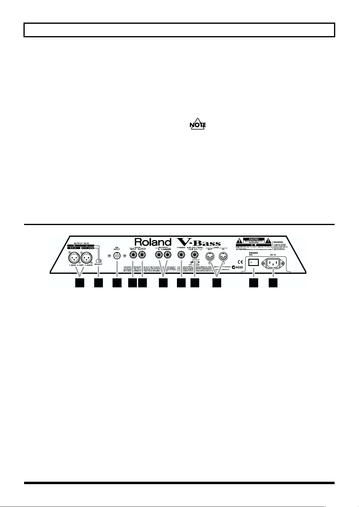
Panel Descriptions
Front Panel
fig.0-01
8
9
1
17
4
10
18
2
6
11 12 13
14 15
3
7
16
20
1. LED Display
It displays the bank number of the currently selected
patch (p. 19). In TUNER MODE (p. 18), it displays the
note name.
2. LCD Display
It displays the various information of the V-Bass, such as
patch's name, the value of parameter, and others.
3. PATCH/VALUE Dial
Use this knob to select patches, or to adjust parameter
values.
4. OUTPUT LEVEL Knob
Use this knob to adjust the total volume of the V-Bass.
* The level of OUTPUT(XLR) and BASS OUTPUT will not
change.
5. GK SETTING Button
Use this button when making settings for the GK Pickup
(p. 15).
6. Function Button
Use these buttons to select parameter on the LCD Display.
5
22
19
21
8. EXIT Button
Use this button to cancel the operation, or when
returning to the Play screen (p. 13).
9. WRITE Button
Use this button to write a patch (p. 30, 31).
10.CURSOR Button
Use these buttons to move a cursor.
11.COSM BASS Button
Press this button for access to COSM BASS parameters
(p. 21).
12.COSM AMP Button
Press this button for access to COSM AMP parameters
(p. 22).
13.EFFECTS Button
Press this button when making adjustments for each
effect (p. 22).
14.PEDAL ASSIGN Button
Press this button when making adjustments for pedal
functions (p. 24).
7. PAGE Button
Use these buttons to switch pages on the LCD Display
(p. 14).
10
15.MASTER Button
Press this button when adjusting patch's level, name,
and others (p. 23, 27–30).
Page 12
Panel Descriptions
16.SYSTEM Button
Press this button when making adjustments for the VBass to be used in various situations (p. 31, 35–42).
17.MANUAL Button
Press this button to use the MANUAL MODE (p. 32).
18.TUNER/BYPASS Button
Press this button to use the TUNER function, or the
BYPASS function (p. 18).
19.BANK Pedal
Press these pedals to switch patch banks, or patches (p. 19).
20.Number Pedals
Press these pedals to switch patches (p. 19), or to switch
effects On/Off (p. 32).
Rear Panel
fig.0-02
21.CTL (Control) Pedal
Use this pedal to control the variety of functions, such as
On/Off for effects, TUNER switch, and others (p. 24).
22.EXP (Expression) Pedal
Use this pedal to control the volume, wah effect, and
others (p. 24).
When operating the expression pedal, be careful not to
get your toes pinched between the moving part and the
panel. In households with small children, an adult should
provide supervision until the child is capable of following
all the rules essential for its safe use. Children should use
this unit under adult supervision and guidance.
23 28 31
23.OUTPUT Jacks (XLR)
These are XLR type connectors that provide balanced
output.
24.SELECT (Output Select) Switch
This switch setting determines whether the signals
output from the OUTPUT jacks (XLR) are in stereo (L/
R), or as DIRECT/MONO output.
DIRECT:
MONO: Outputs the mixed signal of the OUTPUT L/R.
25.GK INPUT Connector
Connect the included GK cable to input signals from
each string.
26.BASS INPUT Jack
Use this jack to input the normal bass pickup signals.
27.BASS OUTPUT Jack
This jack directly outputs the signal from the BASS INPUT.
Outputs the normal pickup signal from the GK
INPUT, or the signal from the BASS INPUT.
25 26 2724 29 30 32 33
28.OUTPUT Jack
These are standard jacks that output unbalanced signals.
29.PHONES (Headphones) Jack
A pair of stereo headphones can be connected to this jack.
30.SUB EXP PEDAL/SUB CTL 1,2
(Sub Expression/Sub Control Pedal) Jacks
Connect an optional expression pedal (such as the EV-5)
or foot switch (such as the FS-5U) here.
31.MIDI Connectors
Connect an external MIDI device to these connectors to
transmit and receive MIDI messages.
32.POWER Switch
Switches the power to the on and off.
33.AC Inlet
Connect the included power cord.
11
Page 13
Chapter 1. Playing Sounds
HOT
COLD
GND
3
12
Attaching the GK pickup
First, attach the GK-2B divided pickup to your bass. For
details on installation, refer to the GK-2B owner’s manual.
The GK-2B cannot be used with the following types of
basses. (Even if installed, it will not function correctly.)
• Basses with an unconventional string configuration, such
as multi-stringed basses with seven or more strings, or
double basses (acoustic string basses)
• Basses that use nylon strings without a steel core, or gut
strings
• Any other basses that, due to their structure, provide no
space for correctly attaching the GK-2B divided pickup
Basically, set the GK-2B select switch to the “MIX” position
when using the V-Bass.
Making Connections
Before making connections
In order to play the V-Bass, you will need the following
equipment.
• A bass with a GK-2B installed
• Amp/speaker or headphones
You may wish to use the following equipment for additional
convenience:
• External expression pedal (Roland EV-5 or BOSS FV300L; sold separately)
• External pedal switch (BOSS FS-5U, FS-5L; sold
separately)
* To prevent malfunction and/or damage to speakers or other
devices, always turn down the volume, and turn off the power
on all devices before making any connections.
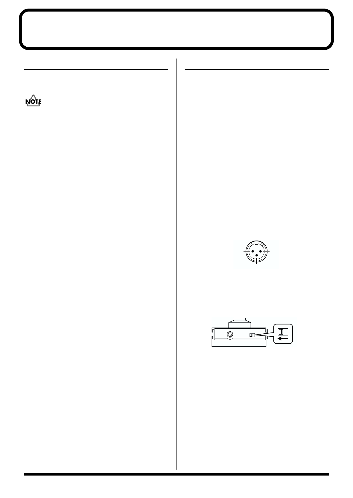
* The pin assignment for the XLR type connectors is as shown
below. Before making any connections, make sure that this pin
assignment is compatible with that of all your other devices.
* Use only the specified expression pedal (EV-5 or BOSS FV-
300L; sold separately). By connecting any other expression
pedal, you risk causing malfunction and/or damage to the unit.
* If connecting the FS-5U, set the polarity switch as follows.
fig.1-02e
Polarity switch
About the BASS OUTPUT jack
As desired, connect your amp or mixer to the BASS OUTPUT
jack.
* Since you can output only the original bass sound from the
BASS OUTPUT jack, use the jack when you wish to process
just the original bass sound through an external effects device.
* If you are using the normal bass input jack of the GK-2B, set
the GK-2B select switch to “MIX.”
* Even when headphones are connected to the PHONES jack,
sound will still be output from the OUTPUT jack, OUTPUT
connector (XLR), and the BASS OUTPUT jack.
12
Page 14
Chapter 1. Playing Sounds
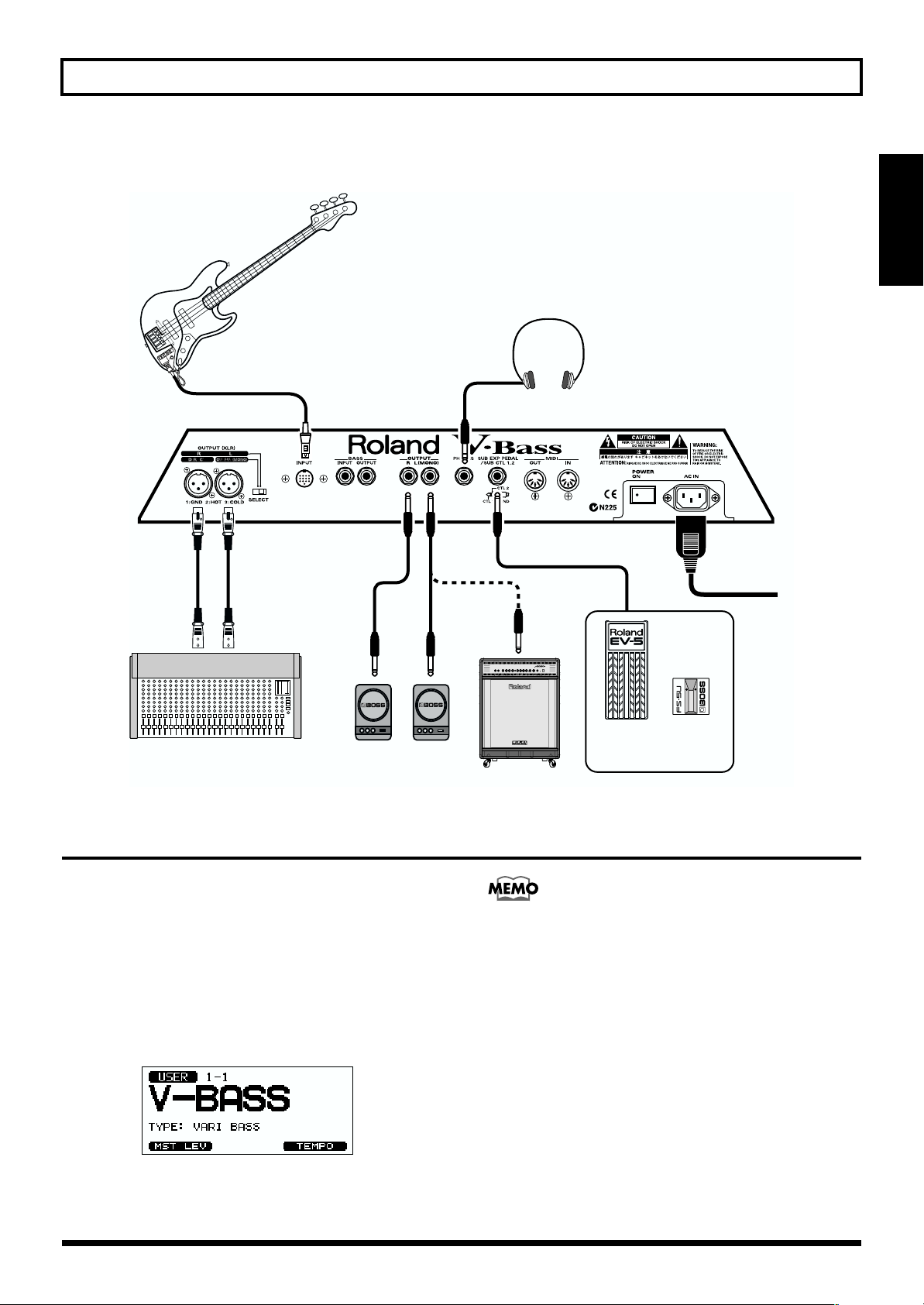
After you have made preparations on your bass (GK-2B), connect your equipment as shown in the following diagram.
fig.1-01e
Stereo Headphones
Bass Guitar
To Power Outlet
Chapter 1
Speaker with AmplifierMixer
Turning On the Power
Once the connections have been completed (p. 12), turn on
power to your various devices in the order specified. By
turning on devices in the wrong order, you risk causing
malfunction and/or damage to speakers and other devices.
1. Turn the POWER switch of the V-Bass to the “ON”
position to turn on the power.
The display will light, and the following screen will
appear. This is called the “Play screen.”
fig.1-03
* When the power is turned on, the patch number that was
selected at the time of the last power-off will be selected.
EV-5
FV-300L
etc.
Bass Amp
FS-5U
FS-5L
etc.
The various procedures described in this owner’s
manual are to be performed from the Play screen, which
you can reach by pressing [EXIT] several times.
* This unit is equipped with a protection circuit. A brief interval
(a few seconds) after power up is required before the unit will
operate normally.
2. Turn on the power of your audio devices (bass amp,
mixer, etc.).
13
Page 15
Chapter 1. Playing Sounds
Adjusting the Volume
Use the OUTPUT LEVEL knob, to set the maximum volume.
fig.1-25
* The output volume from the OUTPUT connector (XLR) will
not change. If you wish to change the volume including that
from the OUTPUT connector (XLR), please adjust the LEVEL
parameter in the GLOBAL section (p. 64).
* You can also adjust the level by assigning the function to the
controls like built-in EXP pedal and GK VOL of the GK-2B.
Please refer to the “Pedal function settings” section for details
(p. 24).
About the display (Basic operation)
Some screens have several pages of parameters. A page icon
is displayed in the upper right of the screen.
fig.1-04e
Page icon
Editing multiple parameters
simultaneously
For parameters that can be set independently for each
string, the settings for all strings can be increased or
decreased simultaneously.
For example, if you want to adjust the amount of
Polyphonic Pitch Shift for each string in the same way,
this means that you need not make the same setting
repeatedly.
The following parameters can be edited simultaneously.
GK SETTING:
• PICKUP<–> BRIDGE (p. 68)
• SENSITIVITY (p. 68)
COSM BASS:
• PICKUP REAR PICKUP OFFSET (p. 45)
• PICKUP FRONT PICKUP OFFSET (p. 45)
• PT SHIFT SHIFT (p. 47)
• PT SHIFT FINE (p. 47)
• PT SHIFT HARMO (p. 47)
• PT SHIFT E.LEVEL (p. 48)
• PT SHIFT D.LEVEL (p. 48)
• PD SHIFT STRING (p. 51)
• POLY OCTAVE -1OCT (p. 51)
• POLY OCTAVE DIR (p. 51)
• PAN STRING (p. 52)
• MIXER STRING LEVEL (p. 52)
fig.1-05
3
12
1. Use PAGE [ ][ ] to switch pages.
2. Press [F1]–[F6] to select the desired parameter.
* You can also use [CURSOR] to select parameters.
3. Turn the VALUE dial to modify the value.
* If you want to save the modified patch (p. 19), refer to “Saving
a sound (patch) you’ve created” (the Write procedure) (p. 30).
1. Access the screen that includes the parameter you
want to edit.
2. Move the cursor to the parameter that you want to
edit.
3. At this time, [F1]–[F6] correspond to string
numbers Hi,1, 2, 3, 4, and Lo. Hold down the
function button that corresponds to the desired
string, and press [F1]–[F6] to specify the parameter
that you want to set simultaneously.
fig.1-06
4. Press any button to cancel the setting.
14
Page 16
Chapter 1. Playing Sounds
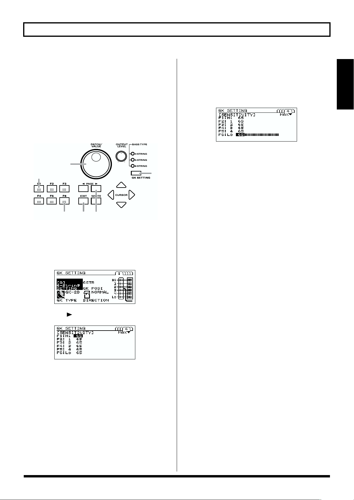
GK pickup settings
Specifying the correspondence for each string
The tonal character of the V-Bass is greatly affected by how
the divided pickup is installed. To ensure that the V-Bass is
functioning at its best, you must input “GK settings” data
that specifies how the divided pickup is installed. These
settings allow the V-Bass to minimize any tonal
inconsistency that might arise from differences in how the
divided pickup was installed.
* For more details, please refer to “GK pickup settings” (p. 33)
or “GK SETTING” (p. 67) section.
If you will be using more than one bass with the V-Bass,
you will need to make GK settings for the divided
pickup of each bass. Perform the following procedure for
each bass. You can make and store settings for up to five
basses.
When playing the V-Bass, GK settings are a very
important element that influences the sound. You must
be sure to make these settings.
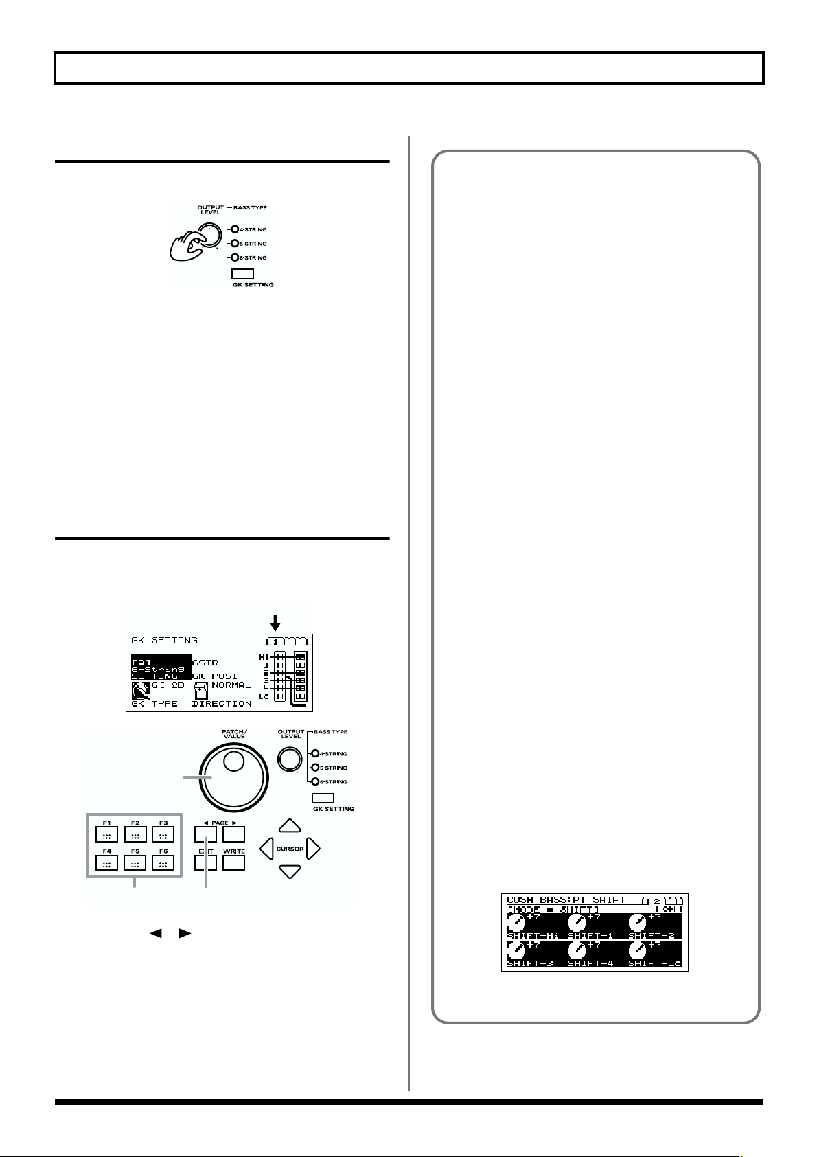
1. Press [GK SETTING]. The following display appears.
fig.1-10
3. Press [F2] (GK POSI).
Specify the position of the pickup. Use the VALUE dial
to specify the position in which the pickup was installed
on your bass.
fig.3-01
4. Press [F4] (GK TYPE).
Specify the GK type. Use the VALUE dial to specify the
type of divided pickup that is installed in your bass.
fig.1-12
GK-2B:
Select this if your divided pickup is the GK-2B.
PIEZO1, PIEZO2:
Select one of these if your divided pickup is a piezo-type.
Select a type that matches your bass to produce the best
COSM BASS sound.
* Select “PIEZO1” or “PIEZO2” if you are using a piezo-type
pickup. Piezo-type pickups detect string vibration by using a
piezo-electric element attached to the bridge of the bass.
5. Press [F5] (DIRECTION).
Specify the position of the pickup. Use the VALUE dial
to specify the position in which the pickup is installed on
your bass.
fig.1-13
Chapter 1
fig.1-11
2. Press [F1] (SETTING).
Select a set of GK settings. Use the VALUE dial to select
the GK settings for your bass.
You can store five settings to GK setting A–E.
When you switch basses, you can simply change to the
appropriate set of GK settings that you made earlier,
allowing you to play each bass with the optimal settings.
NORMAL: Positioned with the cable extending toward
the bridge.
REVERSE: Positioned with the cable extending toward
the neck.
15
Page 17
Chapter 1. Playing Sounds
fig.1-14e
NORMAL
string 6 string 1
REVERSE
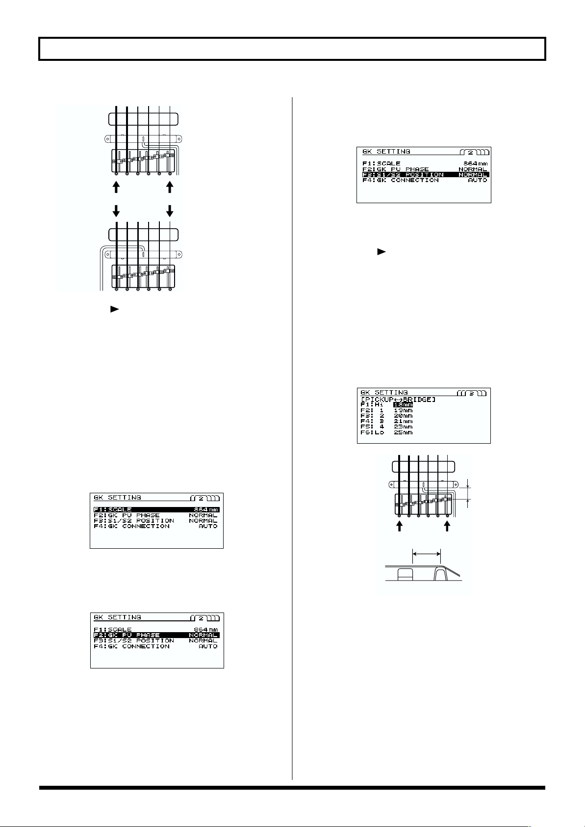
6. Press [PAGE ] to move to page 2.
7. Press [F1] (SCALE).
Use the VALUE dial to specify the scale length of your
bass.
Measure the length from the nut to the bridge of the
highest string (normally G or C string) of your bass.
Then, specify the value within 710–940 mm, or select one
of the 4 presets listed below.
SHORT: 760 mm
MEDIUM: 812 mm
LONG (JB/PB): 864 mm
EXTRA LONG: 914 mm
fig.1-16
9. Press [F3] (S1/S2 POSITION).
Use the VALUE dial to specify whether the function of the
GK-2B’s S1/S2 switches should be exchanged.
fig.1-17
NORMAL: The switches will function normally.
REVERSE:
The S1 switch and S2 switch will be exchanged.
10.Press [PAGE ] to move to page 3.
11.Press [F1]–[F6] to specify the string.
Use the VALUE dial to specify the distance from the
pickup to the bridge. Use a tape measure to actually
measure along each string to find the distance from the
bridge side edge of the divided pickup to the bridge. For
each string, specify the distance in millimeters.
* This setting has no effect if GK TYPE is set to “PIEZO1” or
“PIEZO2”
fig.1-18
fig.1-19e
8. Press [F2] (GK PU PHASE).
Use the VALUE dial to specify the phase of the GK
pickup, to match with the normal pickup.
fig.3-03
While playing lower string of your bass, set this
parameter to the setting that does not cause the volume
to diminish significantly.
NORMAL: Leave the phase unchanged.
INVERSE: Invert the phase.
16
string 6 string 1
String
BridgePickup
12.If you will be using the V-Bass with more than one
bass, repeat steps 2–11 to make the appropriate GK
settings for each bass.
13.Press [EXIT] to return to the Play page.
* These settings must be made when you newly attach a divided
pickup to a bass, or when you adjust the height of a divided
pickup. Once you have made these settings correctly, they will
be remembered even when the power is turned off. It is not
necessary to re-make them each time you perform.
* When you want to play the V-Bass using a bass that is different
than the previously used bass, select one of the settings A–E
that you made in step 2, to choose GK settings appropriate for
your bass. Press [EXIT] to return to the Play page.
Page 18
Chapter 1. Playing Sounds
Adjusting the sensitivity of each string
Adjust the pickup sensitivity for each string, according to the
way in which the GK-2B divided pickup is installed.
If you have more than one bass that you want to use with the
V-Bass, you must adjust the sensitivity of the divided pickup
for each bass. For each bass, turn off the power of the V-Bass,
connect the next bass, and perform the following procedure.
Settings for up to five basses can be made and stored.
fig.1-20
7
3
5
10
4
1. Press [GK SETTING].
2. Press [F1] (SETTING).
Use the VALUE dial to select the GK setting that you
want to name.
fig.1-11
2
5. Play string 6 of your bass.
* Play the string appropriate for your bass.
The level meter will be displayed. The indications
appear sequentially (starting from the left) according to
how strongly you play the string.
fig.1-22e
6. Turn the VALUE dial to adjust the sensitivity.
Adjust the sensitivity so it’s as high as you can get it
without causing the large level meter at the far right to
appear when you play most strongly in an actual
performance.
Then adjust the balance by ear.
* If the large level meter at the far right is displayed, an overload
has occurred. Reduce the sensitivity.
* Depending on the bass you use, the level meter may move all
the way to maximum even if the sensitivity is set as low as
possible. If this occurs, set the GK-2B divided pickup at a
greater distance away from the strings than specified.
7. Adjust the sensitivity of strings 5–1 in the same way.
8. Next, play strings 6–1 very softly.
If there is a string that sounds louder than the others,
lower the sensitivity for that string so that the volume is
consistent among all strings.
Chapter 1
3. Press [PAGE ] several times to access page 4.
fig.1-21e
4. Press [F6] to select string 6.
* Select strings as appropriate for the bass you are using.
9. Press [EXIT] to return to the Play page.
* These settings must be made when you newly install a divided
pickup, or when you adjust the height of the divided pickup.
Once you have made these settings correctly, they are retained
even while the power is turned off. It is not necessary to remake these settings each time you perform.
* When you want to play the V-Bass using a bass that is
different than the previously used bass, select one of the
settings A–E that you made in step 2, to choose GK settings
appropriate for your bass. Press [EXIT] to return to the Play
page.
17
Page 19
Chapter 1. Playing Sounds
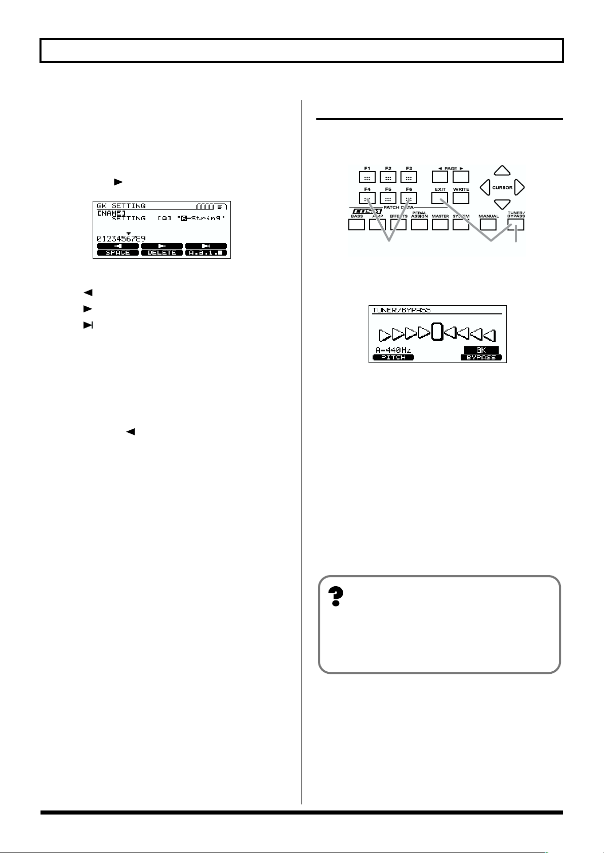
Naming your settings
1. Press [GK SETTING].
2. Press [F1] (SETTING).
Select the GK setting that you want to name.
3. Press [PAGE ] to move to page 5.
fig.1-23
4. Use [F1]–[F6] and the VALUE dial to assign a name.
[F1] ( ): Move the cursor to the left.
[F2] ( ): Move the cursor to the right.
[F3] ( ): Move the cursor to the end.
[F4] (SPACE): Insert a space at the cursor location.
[F5] (DELETE): Delete a character. The characters that
follow get shifted to the left.
[F6] (A, a, 1, ■): Switch between entering uppercase
letters, lowercase letters, numbers, and
characters.
* Press [CURSOR ] to return to the previous page.
5. Press [EXIT] to return to the Play page.
* These settings remain stored in memory even while the power
is off.
Tuning your bass
Here’s how to use the Tuner function of the V-Bass to tune
your bass.
fig.1-07
12 7
1. Press [TUNER/BYPASS]. The Tuner function will be
turned on.
fig.1-08
2. Use the function buttons to make the following
settings.
Press the button for the function that you want to set
([F4] [F6]), and turn the VALUE dial to select the desired
value.
* This step is not required if you do not want to edit the
parameter. Proceed to step 3.
[F4] (PITCH: 435Hz–445Hz)
Set the standard pitch.
* This was set to 440Hz when the unit was shipped from the
factory.
* A pitch of the HARMONIST depends on this setting.
What is the standard pitch?
The standard pitch is the frequency of the A4 note
(middle A on a piano) of the instrument that is used as
the pitch reference for a performance.
[F6] (BYPASS: MUTE, GK, BASS IN)
Select the sound while you are tuning.
MUTE: The sound will be muted.
GK: Outputs the sound of the GK pickup.
BASS IN: Outputs the sound of the normal pickup.
* This was set to “GK” when the unit was shipped from the
factory.
18
Page 20
Chapter 1. Playing Sounds
3. Play a single note on the open string that you want to
tune.
The LED display will indicate the note name closest to
the pitch of the string you played.
* You must cleanly play a single note on only the string to be
tuned.
fig.1-09
CC
F
4. Tune your bass so that the display shows the note name
of the string you are tuning.
5. While watching the screen, tune so that only the center
indicator is lit.
6. Repeat steps 3–5 to tune each string.
* If you are tuning a bass with a vibrato arm, tuning one string
may cause the other strings to drift. If this occurs, first tune
each string approximately so that the note name is displayed,
and then re-tune each string several times.
7. When you have finished tuning, press [TUNER/
BYPASS] or [EXIT].
You can also switch to Tuner mode using pedals.
When you are in Play screen (p. 13), or in Manual Mode
(p. 32), press the [BANK▲] and [BANK▼] pedals
simultaneously.
Press either the [BANK▲] or [BANK▼] pedal to return
to the original mode.
#
D D
#
G
G
#
#
AA#B
E F
Switching sounds (patches)
What is a patch?
The V-Bass contains 200 different sounds, known as
“patches.”
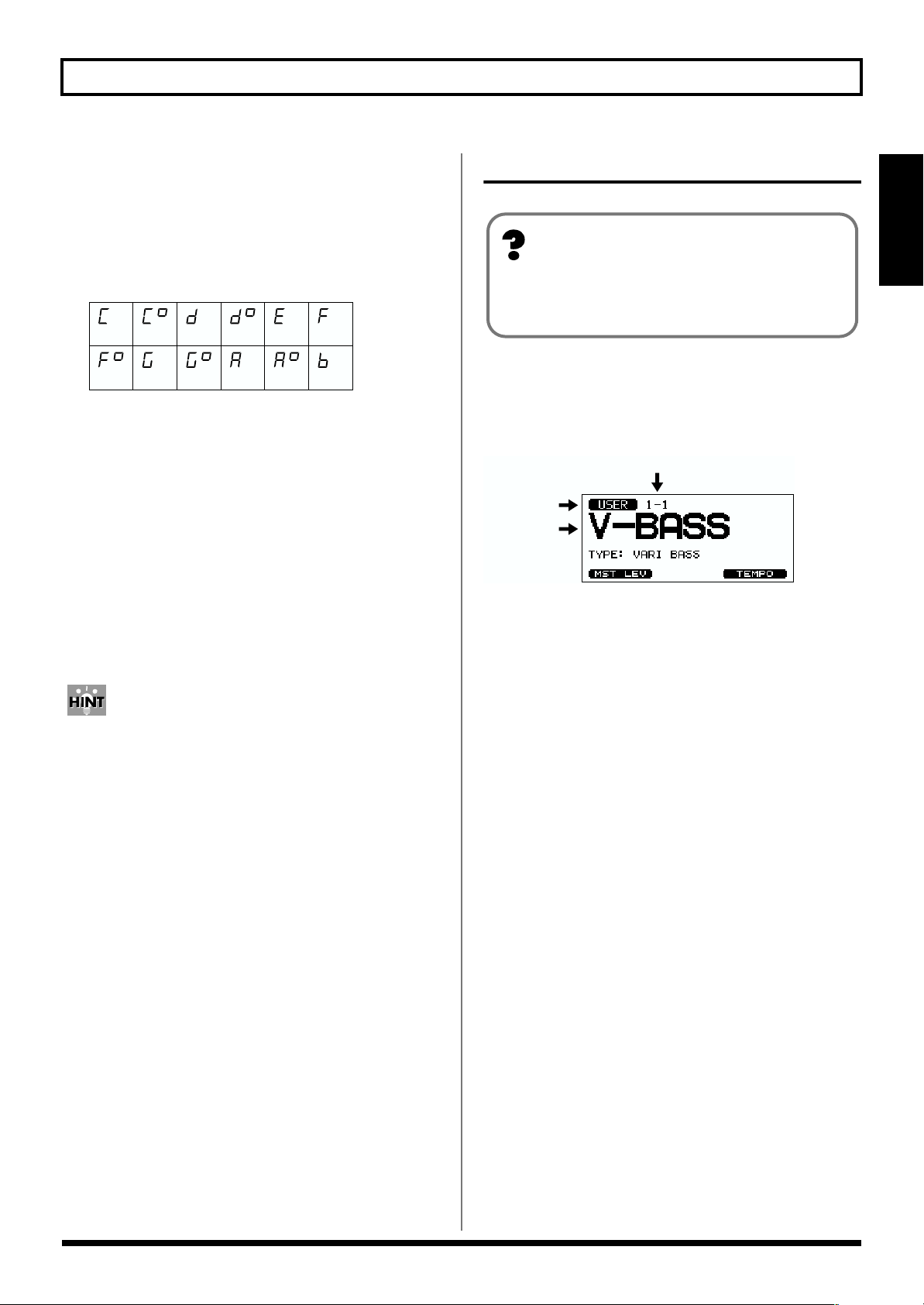
About the patch numbers
In the Play screen, the patch number (bank number) and
patch name are displayed as follows.
fig.1-50
Patch Number
User Pach/
Preset Patch
Patch Name
User Patch
When the V-BASS is shipped from the factory, it contains 100
user patches. You are free to modify and save these anew.
1-1 2-1 . . . 25-1
1-2 2-2 . . . 25-2
1-3 2-3 . . . 25-3
1-4 2-4 . . . 25-4
Preset Patch
The V-BASS contains 100 preset patches.
26-1 27-1 . . . 50-1
26-2 27-2 . . . 50-2
26-3 27-3 . . . 50-3
26-4 27-4 . . . 50-4
Preset patches can be edited – i.e., you can modify their
settings – but cannot be saved again as presets. If you wish to
save a modified preset patch, you must store it as a new user
patch.
(Bank - Number)
Chapter 1
19
Page 21
Chapter 1. Playing Sounds
Using the PATCH/VALUE dial to change
Here’s how you can change from one patch to the next one.
* If the System parameter “DIAL” is set to “VALUE ONLY,”
the PATCH/VALUE dial cannot be used to select patches.
1. Make sure that you are in Play page.
If you are not in Play page, press [EXIT] several times.
2. Turn the PATCH/VALUE dial to change patches.
Turning the PATCH/VALUE dial toward the right will
select the next-numbered patch; turning it toward the
left will select the previous-numbered patch.
fig.1-26
Using pedals to change
This method is convenient during a live performance or in
the studio. You can press pedals to specify the bank and
number.
If you set the System parameter “BANK AREA,” patches will
change within the specified bank area.
1. Make sure that you are in Play page.
If you are not in Play page, press [EXIT] several times.
2. Select the patch bank.
Use [BANK ▼] [BANK ▲] to select the desired bank.
* If you do not need to leave the currently selected bank, this
step is not necessary. Proceed to Step 3.
fig.1-27
3. Step on a number pedal [1]–[4] to select a patch
number.
fig.1-28
20
Page 22
Chapter 2. Creating sounds
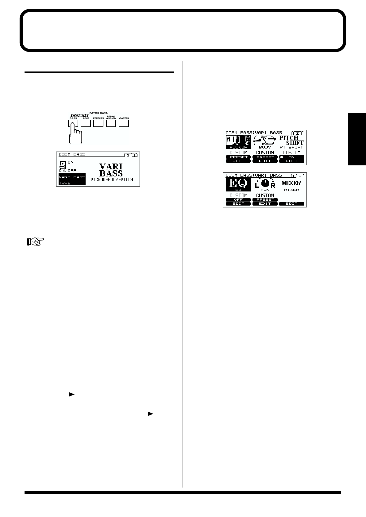
COSM BASS settings
Here’s how to make COSM BASS settings. Make these
settings as desired.
1. Press [COSM BASS].
fig.2-01
fig.2-01a
2. Press [F1] (ON/OFF).
3. Turn the VALUE dial to switch COSM BASS on/off.
4. Press [F4] (TYPE), and use the VALUE dial to select the
COSM BASS type.
COSM BASS “TYPE” (p. 43)
• ACOUSTIC
• ELECTRIC
• FRETLESS
• VARI BASS
• WAVE SYNTH
• OSC SYNTH
• FILTERED
• BOWED
• PIPE
• CRYSTAL
• ORGAN
• BRASS
• PEDAL PITCH SHIFT
• POLY OCTAVE
• POLY DISTORTION
• POLY SLOW GEAR
5. Press [PAGE ].
* Page 2 and following contain sections that determine the
[COSM BASS] tone. Each time you press [PAGE ], you
will move to the setting screen for the next section. You can
also move to the setting screen of the next section by pressing
[COSM BASS].
6. Press [F1]–[F3] to select the section.
* *F1]–[F3] will work as “ON/OFF” switch for the section with
“ON” or “OFF” icon.
The section without icon (such as MIXER section) will always
be turned “ON”.
7. Turn the VALUE dial, and select “CUSTOM” or
PRESETs for each section.
fig.2-02
fig.2-03
* PRESET is a recommended preset settings for each section.
For example, PRESETs for the BODY section in the VARI
BASS would be VIOLIN, SEMI-HLW, and HUGE WD.
There are no PRESETs for section without “PRESET”,
“ON”, or “OFF” icon.
* If you select CUSTOM, the settings you specified by pressing
“EDIT [F4]–[F6]” will be selected.
* Even though you have selected a PRESET, the display will
turn to CUSTOM, when you edit a parameter, or execute
Write procedure (p. 30).
8. If you want to perform detailed editing of the
parameters of a section, press “EDIT [F4]–[F6]” to move
to the editing screen for each section.
9. Press [F1]–[F6] to specify the parameter that you want
to adjust, and use the VALUE dial to adjust the value.
10.Adjust the parameters until you get the desired sound.
11.To save the edited values, perform the Write procedure
(p. 30).
* If you do not want to save, press [EXIT] to return to the Play
screen.
Chapter 2
21
Page 23
Chapter 2. Creating sounds
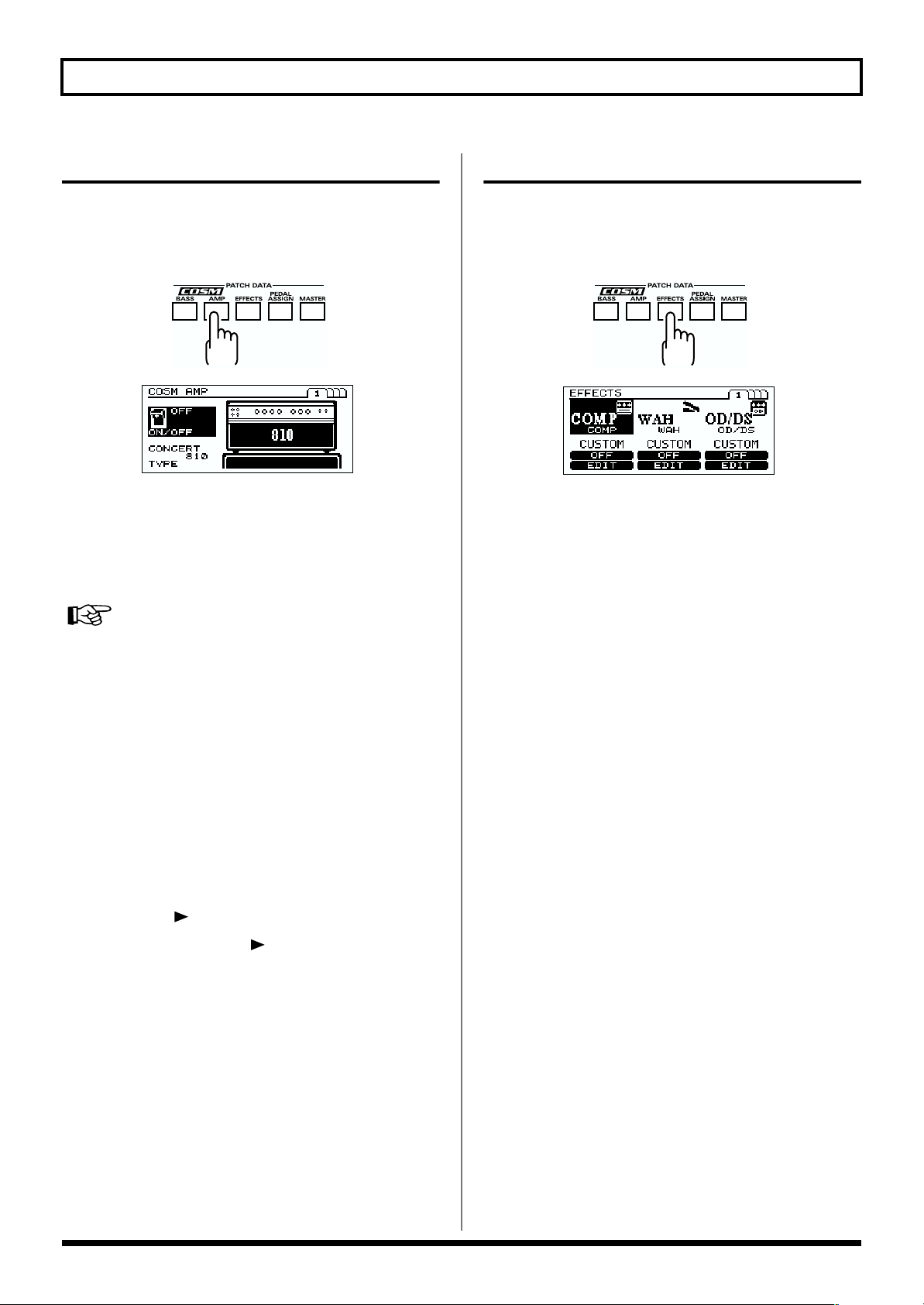
COSM AMP settings
Here’s how to make COSM AMP settings. Make these
settings as desired.
1. Press [COSM AMP].
fig.2-04
fig.2-05
2. Press [F1] (ON/OFF).
3. Turn the VALUE dial to switch COSM AMP on/off.
4. Press [F4] (TYPE), and use the VALUE dial to select the
COSM AMP type.
COSM AMP “TYPE” (p. 53)
• CONCERT 810
• FLIP TOP
• B-MAN
• VO DRIVE
• SESSION
• T.E.
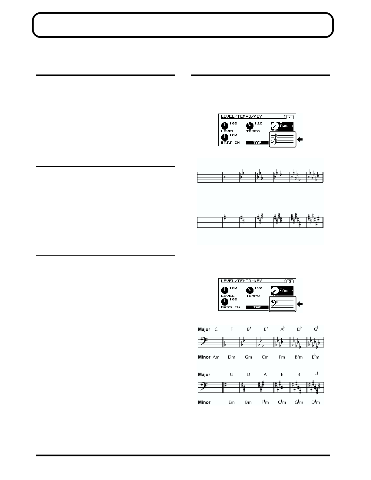
• BASS 360
• SUPER FLAT
• AC BASS
• MS STACK
• Hi-GAIN STACK
• METAL STACK
5. Press [PAGE ].
EFFECTS settings
Here’s how to make effect settings. Make these settings as
desired.
1. Press [EFFECTS].
fig.2-06
fig.2-07
2. Press [F1]–[F3] to switch each effect on/off.
* Each time you press [PAGE], you will move to the next effect
setting screen. You can also move to the next effect setting
screen by pressing [EFFECTS].
* In page 4, press [F1] or [F3] to select a parameter, and [F6]
(SET PDL) to assign “FV LEVEL” to the built-in EXP pedal.
3. Turn the VALUE dial to select “CUSTOM” or
“PRESET.”
4. If you want to edit the effect parameters in more detail,
press “EDIT [F4]–[F6].”
5. Press [F1]–[F6] to select the parameter that you want to
edit, and use the VALUE dial to edit the value.
6. Edit the parameters until you get the sound you want.
7. If you want to save the edited settings, perform the
Write procedure (p. 30).
* If you do not want to save, press [EXIT] to return to the Play
screen.
* Each time you press [PAGE ], you will move to the next
parameter setting screen. You can also move to the setting
screen for the next section by pressing [COSM AMP].
6. Press [F1]–[F6] to select the parameter that you want to
edit, and use the VALUE dial to edit it.
7. Edit the parameters until you get the sound you want.
8. If you want to save the edited settings, perform the
Write procedure (p. 30).
* If you do not want to save, press [EXIT] to return to the Play
screen.
22
Page 24
Chapter 2. Creating sounds
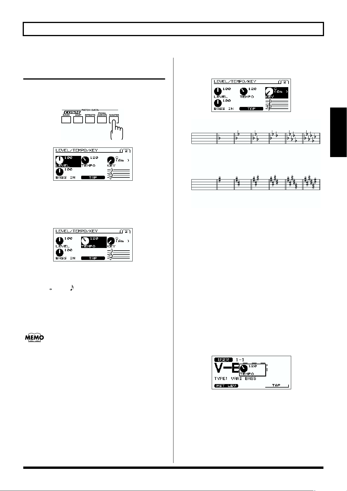
Specifying the tempo and key of the song to be played
Here’s how to specify the tempo and key of a song you’ll be playing.
1. Press [MASTER] twice.
fig.2-08
fig.2-09
* For details on how to adjust the level, refer to “Adjusting the
volume of a patch” (p. 30).
2. Press [F2] (TEMPO), and use the VALUE dial to adjust
the tempo.
fig.2-09b
3. Press [F3] (KEY), and use the VALUE dial to set the
KEY of the Harmonist EFFECTS and COSM BASS.
fig.2-09c
fig.5-50
Major
CF BE
Am Dm Gm Cm Fm BmMinor
Major GDA EB
A
D
G
Em
F
Minor
4. If you want to save the value you specified, perform the
Write procedure (p. 30).
Em Bm FmCmGm
Dm
Chapter 2
* If you want to control the a patch parameter with the adjusted
tempo (p. 63), set the corresponding effect parameter to
“BPM –BPM .”
* If you want to use the MIDI SYNC function, turn the
VALUE dial to the right until the display shows “MIDI.”
* BPM stands for “beats per minute,” and represents the
number of quarter notes played in one minute.
To use Tap Input
Press [F5] (TAP) at least three times, at quarter note
intervals of the desired tempo.
The tempo will be calculated automatically, and set to
the interval at which you pressed the button.
* If you do not want to save, press [EXIT] to return to the Play screen.
You can also set the tempo by using function button on
the PLAY screen.
1. Make sure that you are in the Play screen.
If you are not in the Play screen, press [EXIT] several
times.
2. Press [F6] (TEMPO), and use the VALUE dial to adjust
the tempo.
* To Use Tap Input, Press [F6] (TAP) at least three times, at
quarter note intervals of the desired tempo. The tempo will be
calculated automatically, and set to the interval at which you
pressed the button.
fig.2-09a
3. If you want to save the edited settings, perform the
Write procedure (p. 30).
* If you do not want to save, press [EXIT] to return to the Play
screen.
23
Page 25
Chapter 2. Creating sounds
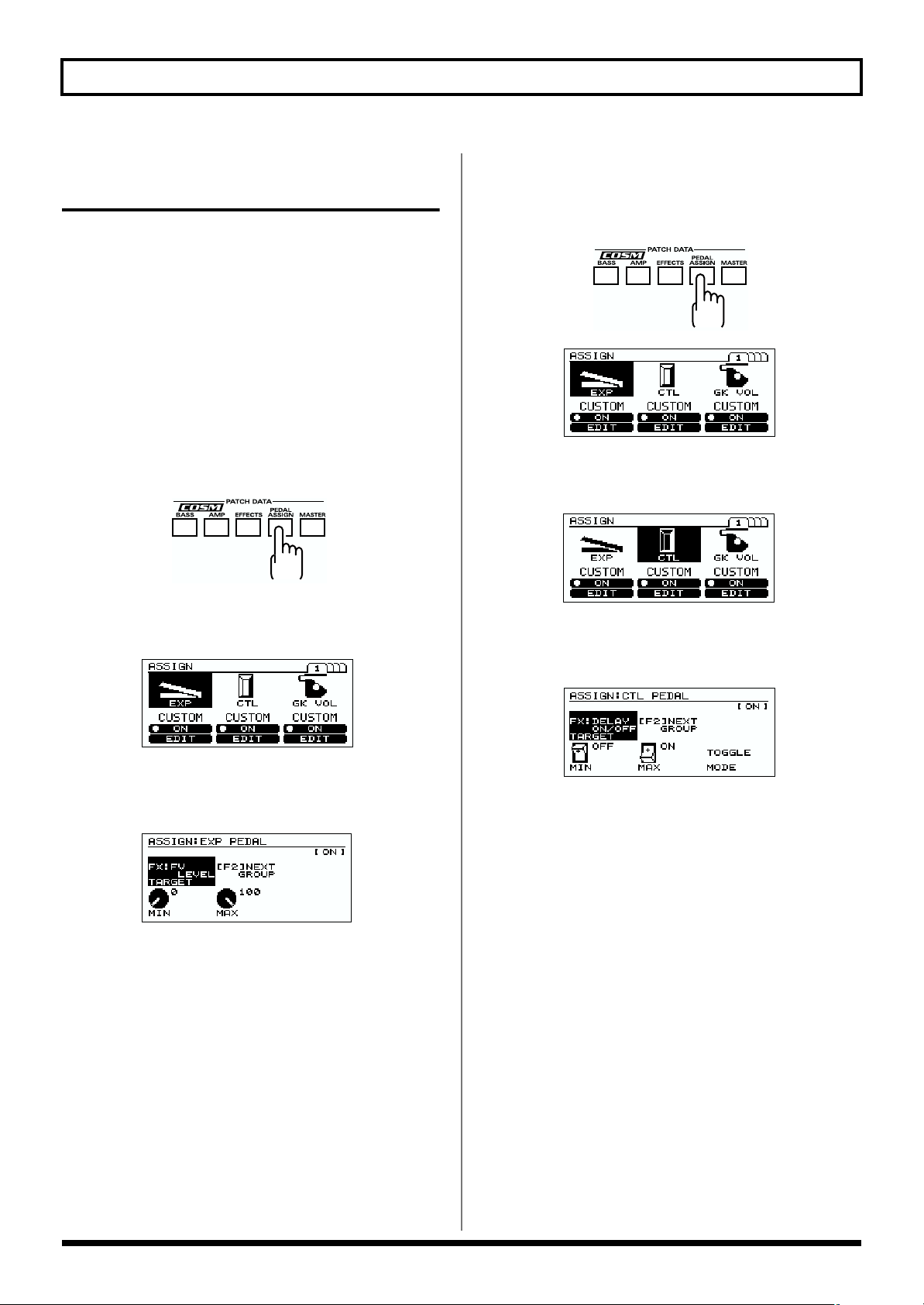
Pedal function settings (EXP/CTL/GK VOL/GK SW)
Make these settings if you want to use the EXP pedal or CTL
pedal of the V-Bass, a pedal connected to the V-Bass, or an
external MIDI device to control parameters while you
perform. For more details, please refer to PEDAL ASSIGN (p.
62) section.
* If you want to use a pedal to control the parameters of an
effect, you must first turn that effect “ON.”
Specifying the function of the V-Bass’s EXP pedal
1. Press [PEDAL ASSIGN].
fig.2-10
2. Press [F1] (ON/OFF) to switch the EXP pedal function
on/off.
fig.2-11
Specifying the function of the V-Bass’s CTL pedal
1. Press [PEDAL ASSIGN].
fig.2-10
fig.2-11
2. Press [F2] (ON/OFF) to switch the CTL pedal function
on/off.
fig.2-13
3.
Turn the VALUE dial to select “CUSTOM” or PRESET.
4. If you wish to edit further, press [F5] (EDIT).
fig.2-14
3. Turn the VALUE dial to select “CUSTOM” or PRESET.
4. If you wish to edit further, press [F4] (EDIT).
fig.2-12
5. Press [F1] (TARGET), and use the VALUE dial to select
the target.
* Press [F2] (NEXT GROUP) to cycle through these choices:
COSM BASS, COSM AMP, the various effects, and FX
BYPASS on/off.
6. Press [F4] (MIN), and use the VALUE dial to specify the
minimum value.
7. Press [F5] (MAX), and use the VALUE dial to specify
the maximum value.
8. If you want to save the edited settings, perform the
Write procedure (p. 30).
* If you do not want to save, press [EXIT] to return to the Play screen.
5. Press [F1] (TARGET), and use the VALUE dial to select
the target.
* Press [F2] (NEXT GROUP) to cycle through these choices:
COSM BASS, COSM AMP, the various effects, and FX
BYPASS on/off.
6. Press [F4] (MIN), and use the VALUE dial to specify the
minimum value.
7. Press [F5] (MAX), and use the VALUE dial to specify
the maximum value.
8. Press [F6] (MODE), and use the VALUE dial to select
the mode.
NORMAL:
TOGGLE: The MIN value and MAX value will
9. If you want to save the edited settings, perform the
Write procedure (p. 30).
* If you do not want to save, press [EXIT] to return to the Play screen.
The value will be MAX while you press the CTL
pedal, and MIN when you release the CTL pedal.
alternate each time you press the CTL pedal.
24
Page 26

Chapter 2. Creating sounds
Specifying the function of GK VOL
* In SYSTEM menu GK FUNC, set GK VOL to
“ASSIGNABLE.” (p. 38).
1. Press [PEDAL ASSIGN].
fig.2-10
fig.2-11
2. Press [F3] (ON/OFF) to the GK VOL function on/off.
fig.2-15
Specifying the function of GK SW
* In SYSTEM menu GK FUNC, set DOWN/S1 and UP/S2 to
“ASSIGNABLE.” (p. 38)
1. Press [PEDAL ASSIGN].
fig.2-10
Chapter 2
fig.2-11
2. Press [PAGE ] to move to page 2.
fig.2-17
3.
Turn the VALUE dial to select “CUSTOM” or PRESET.
4. If you wish to edit further, press [F6] (EDIT).
fig.2-16
5. Press [F1] (TARGET), and use the VALUE dial to select
the target.
* Press [F2] (NEXT GROUP) to cycle through these choices:
COSM BASS, COSM AMP, the various effects, and FX
BYPASS on/off.
6. Press [F4] (MIN), and use the VALUE dial to specify the
minimum value.
7. Press [F5] (MAX), and use the VALUE dial to specify
the maximum value.
8. If you want to save the edited settings, perform the
Write procedure (p. 30).
* If you do not want to save, press [EXIT] to return to the Play
screen.
3. Press [F1] (ON/OFF) to switch the GK SWfunction on/off.
4. Turn the VALUE dial to select “CUSTOM” or PRESET.
5. If you wish to edit further, press [F4] (EDIT).
fig.2-18
6. Press [F1] (TARGET), and use the VALUE dial to select
the target.
* Press [F2] (NEXT GROUP) to cycle through these choices:
COSM BASS, COSM AMP, the various effects, and FX
BYPASS on/off.
7. Press [F4] (MIN), and use the VALUE dial to specify the
minimum value.
8. Press [F5] (MAX), and use the PVALUE dial to specify
the maximum value.
9. Press [F6] (MODE), and use the VALUE dial to select
the mode.
* If you set MODE to “TOGGLE,” the S1 switch and S2 switch
will have the same function (p. 63).
10.If you want to save the edited settings, perform the
Write procedure (p. 30).
* If you do not want to save, press [EXIT] to return to the Play screen.
25
Page 27

Chapter 2. Creating sounds
Max.Value
Min.Value
04080
127
T arget
Max
T arget
Min
Act.RangeLoAct.Range
Hi
OFF
On
Off
Median
Value
ON
0408060
127
Act.Range
Lo
Act.Range
Hi
Assign function settings
Set this when you want to control parameters using an
external pedal or MIDI device connected to the V-Bass. You
can also make settings to control several parameters
simultaneously. For each patch number, you can specify
eight parameters (Assign numbers 1–8) that will be
controlled by a controller you specify.
* As an example here, we will describe how to make settings for
Assign 1. You can use the same procedure for making Assign
settings 2–8.
1. Press [PEDAL ASSIGN].
fig.2-10
fig.2-11
2. Press [PAGE ] to move to page 2.
fig.2-17
7. Press [F4] (MIN), and use the VALUE dial to specify the
minimum value.
8. Press [F5] (MAX), and use the VALUE dial to specify
the maximum value.
9. Press [F3] (SOURCE), and use the VALUE dial to select
the source.
10.Press [F6] (MODE), and use the VALUE dial to select
the mode.
11.Press [PAGE ] to move to page 2.
fig.2-21
12. Press [F1], and use the VALUE dial to set ACTIVE
RANGE LO.
* You can press [F4] (LO SET) to specify the current value of
the source.
13.Press [F2], and use the VALUE dial to set ACTIVE
RANGE HIGH.
* You can press [F5] (HI SET) to specify the current value of the
source.
3. Press [F2] (ON/OFF) to switch the Assign function on/
off.
fig.2-19
4. Turn the VALUE dial to select “CUSTOM” or PRESET.
5. If you wish to edit further, press [F5] (EDIT).
fig.2-20
6. Press [F1] (TARGET), and use the VALUE dial to select
the target.
* Press [F2] (NEXT GROUP) to cycle through these choices:
COSM BASS, COSM AMP, the various effects, and FX
BYPASS on/off.
26
14.If you want to save the edited settings, perform the
Write procedure (p. 30).
* If you do not want to save, press [EXIT] to return to the Play screen.
Active Range:
about the variable range of a controller
This setting specifies the operating range in which the value
will change when the source you are using is a continuously
variable controller, such as an expression pedal. Even if you
move the controller outside of this range, the value will not
change; it will stay at the “minimum value” or “maximum
value.”
(Example)
When ACTIVE RANGE LO:40 and ACTIVE RANGE HI:80
fig.2-22a
* If you are using an on/off type controller such as a foot switch
as the source, please leave this at the “LO:0” and “HI:127”
settings. With other settings, the value may fail to change.
Page 28

Chapter 2. Creating sounds
Reverb
Chorus
Delay
Modulation
Noise Suppressor
Equalizer
Foot Volume
COSM bass sound produced
from the GK pickup
Overdrive/Distortion
Wah
Compressor/Limiter
COSM amp
Mixer Point
Normal pickup input
Adjusting the level of the normal pickup
1. Press [MASTER] twice.
fig.2-08
fig.2-09
2. Press [F4] (BASS IN), and use the VALUE dial to adjust
the value.
fig.2-23a
Exchanging the connection order of the internal multi-effect and the COSM BASS/COSM AMP
1. Press [MASTER].
fig.2-08
Chapter 2
fig.2-23
2. Press [F5] (EDIT).
fig.2-24
3. If you want to save the edited settings, perform the
Write procedure (p. 30).
* If you do not want to save, press [EXIT] to return to the Play
screen.
fig.2-25
3. Use [CURSOR] to select the effect that you want to
move.
4. Turn the VALUE dial to move the effect.
5. If you want to save the edited settings, perform the
Write procedure (p. 30).
* If you do not want to save, press [EXIT] to return to the Play
screen.
27
Page 29

Chapter 2. Creating sounds
Combining the normal input with the GK input
COSM BASS lets you create sounds by combining the inputs
of the divided pickup and normal pickup.
Adjust the volume balance.
1. Press [COSM BASS].
fig.2-01
fig.2-01a
2. Press [PAGE ] twice to move to page 3.
fig.2-03
Specify the connection position
1. Press [MASTER].
fig.2-08
fig.2-23
2. Press [F5] (EDIT).
3. Use [CURSOR] to move to the mixer point.
fig.2-50
Mixer point
3. Press [F6] (EDIT).
4. Press [F1] (BALANCE).
fig.2-26
5. Turn the VALUE dial to adjust the balance between the
COSM bass sound and the sound of the normal pickup.
CB: COSM bass sound
NP: Normal pickup sound
6. Press [PAGE ] to move to page 2.
fig.2-26a
* You can press [F3] (MIX MODE) to exchange the divided
pickup and normal pickup.
4. Turn the VALUE dial to move the mixer point.
fig.2-27
5. When you finish making settings, perform the Write
procedure (p. 30) if you want to save the sound.
* If you do not want to save, press [EXIT] to return to the Play
screen.
7. Press [F1]–[F6], and use the VALUE dial to specify the
volume for each string.
8. If you want to save the edited settings, perform the
Write procedure (p. 30).
* If you do not want to save, press [EXIT] to return to the Play screen.
28
Page 30

Normal pickup sound
If you use the CHAIN function to set the connection
location of the COSM bass to anywhere other than the
beginning of the chain, the normal pickup sound
processed from the beginning of the effect chain will be
output together with the normal pickup sound that is
mixed by the COSM bass mixer.
You can take advantage of this capability to create
sounds that combine these two:
1. COMPRESSOR, WAH, AMP, etc., applied to the
normal pickup sound
2. Only spatial-type effects applied to the synth
sound of the COSM section
fig.2-27
Chapter 2. Creating sounds
Naming a patch
Here’s how to assign a name to a patch you’ve created.
1. Press [MASTER].
fig.2-08
Chapter 2
fig.2-23
2. Press [F4] (EDIT).
fig.2-28
* If you want to independently control the volume of “1.”
above, assign the effect level before the COSM bass to the
GK VOL etc. of the GK-2B. (p. 25)
3. Use [CURSOR] to move the cursor to the location
where you want to enter a character.
4. Use the VALUE dial to select a character.
As you turn the VALUE dial, the character guide will
automatically switch between uppercase letters,
lowercase letters, and symbols.
By pressing [F1]–[F6] you can perform the following
convenient operations.
[F1] ( ): Move the cursor to the left.
[F2] ( ): Move the cursor to the right.
[F3] ( ): Move the cursor to the end.
[F4] (SPACE): Insert a space at the cursor location.
[F5] (DELETE): Delete a character. The characters that
follow get shifted to the left.
[F6] (A, a, 1, ■): Switch between uppercase letters,
lowercase letters, numbers, and
characters.
5. Repeat steps 3–4 to specify the desired patch name.
6. If you want to save the edited settings, perform the
Write procedure (p. 30).
* If you do not want to save, press [EXIT] to return to the Play
screen.
29
Page 31

Chapter 2. Creating sounds
Adjusting the Volume of a Patch
If there are discrepancies in volume between patches, you
can adjust the level.
1. Press [MASTER] twice.
fig.2-08
fig.2-09
2. Press [F1] (LEVEL), and use the VALUE dial to adjust
the value.
fig.2-29
Saving a sound (patch) you’ve created (the Write procedure)
Sound settings you modify are temporary, and will return to
their previous settings if you switch to another patch.
If you want to keep the settings you modify, perform the
Write procedure.
fig.2-31
2
1, 3
1. Press [WRITE].
The Write screen will appear.
fig.2-32
3. If you want to save the edited settings, perform the
Write procedure (p. 30).
* If you do not want to save, press [EXIT] to return to the Play
screen.
As an alternative to this method, you can also use function
buttons in the Play screen to make the adjustment.
1. Make sure that you are in the Play screen.
If you are not in the Play screen, press [EXIT] several
times.
2. Press [F4] (MST LEV), and use the VALUE dial to
adjust the value.
fig.2-30
3. If you want to save the edited settings, perform the
Write procedure (p. 30).
* If you do not want to save, press [EXIT] to return to the Play
screen.
2. Turn the VALUE dial to select the save-destination
patch number.
3. To save the patch, press [WRITE].
When the patch is saved, the display will indicate “NOW
WRITING,” and then you’ll be returned to the Play
screen.
* If you do not want to save, press [EXIT] to return to the Play
screen.
30
Page 32

Chapter 2. Creating sounds
Changing the order of patches (Patch Exchange function)
Use this when you want to change the order of patches.
It is not possible to change the order of the preset patches.
fig.2-33
4,6
3
5
1. Press [WRITE].
fig.2-32
2,7
18
Adjusting the sound of the entire V-Bass according to the performance conditions
You can adjust the sound of all patches in common.
Chapter 2
If the location in which you are performing has more
reverberation than the location in which you created the
patches (for example, if you are performing live), you
can use this function to lower the reverb level of all
patches, instead of having to individually edit the reverb
level of each patch.
1. Press [SYSTEM].
fig.2-37
fig.2-60
2. Press [F6] (EXCHANGE).
The Exchange screen will appear.
fig.2-34
3. Press [F1] (PATCH A).
4. Turn the VALUE dial to select one of the patches that
you want to exchange.
5. Press [F4] (PATCH B).
fig.2-35
6. Turn the VALUE dial to select the other patch that you
want to exchange.
7. Press [F6] (EXCHANGE) to exchange the two patches.
The display will indicate “NOW EXCHANGING.”
2. Press [F1] (GLOBAL).
fig.2-36
3. Press [F1]–[F6] to select the parameter that you want to
adjust, and use the VALUE dial to adjust the value.
4. Adjust the parameters (p. 64) until you get the sound
you want.
5. Press [EXIT] several times to return to the Play page.
* These settings remain stored in memory even while the power
is off. You do not need to perform the Write procedure (p. 30).
8. Press [EXIT] twice to return to the Play page.
31
Page 33

Chapter 2. Creating sounds
Using the pedals to turn each effect on/off (Manual mode)
The V-Bass provides a Manual mode in which the number
pedals can be used to switch the specified effect unit on/off.
By using Manual mode, you can switch the specified effect
unit on/off without changing the patch number.
* When Manual mode is on, you can change patches by using
▲
[BANK
Switching to Manual mode
< Using the panel to switch >
1. Manual mode is toggled on/off by pressing
[MANUAL].
When Manual mode is on, the indication in the display
will be as follows.
The effect names corresponding to pedals [1]–[4] will be
highlighted according to whether they are on or off.
fig.2-88
][BANK ▼] or the PATCH/VALUE dial.
Selecting the effects to be turned off by each pedal
fig.2-89
3
1
1. With Manual mode turned on, press [F6] (EDIT) to
access the following screen.
fig.2-90
2. Use CURSOR [▲][▼] to move the cursor to the pedal
whose setting you want to change.
2
2. Each time you press pedal [1]–[4], the specified effect
will be switched on/off.
< Using the CTL pedal to switch >
By making the appropriate setting, you can switch Manual
mode on/off by pressing the CTL pedal. When Manual
mode is on, the CTL pedal indicator will light, and the
display will show the effects corresponding to each pedal.
If you want to use the CTL pedal to switch Manual mode
on/off, make the following settings in “Specifying the
function of the V-Bass’s CTL pedal” (p. 24).
CTL PEDAL: ON
CTL PEDAL TARGET: MANUAL ON/OFF
CTL PEDAL MIN: OFF
CTL PEDAL MAX: ON
CTL PEDAL MODE: TOGGLE
3. Use the VALUE dial to select the effect that will
correspond to that pedal.
4. Repeat steps 2–3 to select the effect that will correspond
to each pedal.
5. Press [MANUAL] to return to the Play page.
* These settings remain stored in memory even while the power
is off. You do not need to perform the Write procedure (p. 30).
32
Page 34

Chapter 3. System settings
GK pickup settings
Select the GK pickup setting
1. Press [GK SETTING].
fig.1-11
2. Press [F1] (SETTING).
3. Turn the VALUE dial to select the GK setting (A–E) in
which the settings are to be saved.
4. Press [EXIT] to return to the Play page.
Setting the GK pickup appropriately for the bass you are using
1. Press [GK SETTING].
8. Press [F5] (DIRECTION).
fig.1-13
9. Turn the VALUE dial to specify the direction in which
the divided pickup is attached.
10.Press [EXIT] to return to the Play page.
Specifying the scale length of the bass you are using
1. Press [GK SETTING].
2. Press [F1] (SETTING).
3. Turn the VALUE dial to specify the GK setting (A–E) in
which the settings are to be saved.
4. Press [PAGE ] to display page 2.
fig.1-16
Chapter 3
2. Press [F1] (SETTING).
3. Turn the VALUE dial to specify the GK setting (A–E) in
which the settings are to be saved.
4. Press [F2] (GK POSI).
fig.3-01
5. Turn the VALUE dial to specify the location at which
the divided pickup is attached.
6. Press [F4] (GK TYPE).
fig.1-12
GK-2B:
Select this if the divided pickup is a GK-2B.
PIEZO1, PIEZO2:
Select one of these if your divided pickup is a piezo-type.
Select a type that matches your bass to produce the best
COSM BASS sound.
5. Press [F1] (SCALE).
6. Turn the VALUE dial to select the scale length.
7. Press [EXIT] to return to the Play page.
7. Turn the VALUE dial to specify the type of divided
pickup.
33
Page 35

Chapter 3. System settings
Matching the phase of the GK pickup and normal pickup
1. Press [GK SETTING].
2. Press [F1] (SETTING).
3. Turn the VALUE dial to select the GK setting (A–E) in
which the settings are to be saved.
4. Press [PAGE ] to access page 2.
5. Press [F2] (GK PU PHASE).
fig.3-03
6. Turn the VALUE dial to select the phase of the pickup.
While playing lower string of your bass, set this
parameter to the setting that does not cause the volume
to diminish significantly.
NORMAL: Leave the phase unchanged.
INVERSE: Invert the phase.
Specifying the connecting condition with the GK pickup
1. Press [GK SETTING].
2. Press [F1] (SETTING).
3. Turn the VALUE dial to select the GK setting (A–E) in
which the settings are to be saved.
4. Press [PAGE ] to access page 2.
5. Press [F4] (GK CONNECTION).
fig.1-17a
6. Turn the VALUE dial to select the connecting condition
between the unit and the GK pickup.
AUTO: Detect automatically, and switch the settings
appropriately. (Recommended)
ON: Always use the GK connection settings.
OFF: Always use the BASS INPUT settings.
7. Press [EXIT] to return to the Play page.
Specifying the placement of the S1/S2 switches
On some bass guitars with a built-in GK pickup, the location
of the S1/S2 switches is the opposite of an external GK
pickup. Make this setting if you want to exchange the
operation of the switches.
1. Press [GK SETTING].
2. Press [F1] (SETTING).
3. Turn the VALUE dial to select the GK setting (A–E) in
which the settings are to be saved.
4. Press [PAGE ] to access page 2.
5. Press [F3] (S1/S2 POSITION).
fig.1-17
7. Press [EXIT] to return to the Play page.
Specifying the distance between the GK pickup and bridge
* If TYPE is set to “PIEZO1” or “PIEZO2,” this setting has no
effect.
1. Press [GK SETTING].
2. Press [F1] (SETTING).
3. Turn the VALUE dial to select the GK setting (A–E) in
which the settings are to be saved.
4. Press [PAGE ] to access page 3.
fig.1-18
5. Press [F1]–[F6] to select the string.
6. Turn the VALUE dial to specify the distance.
6. Turn the VALUE dial to select the desired setting.
NORMAL: The switches will not be reversed.
REVERSE:
7. Press [EXIT] to return to the Play page.
The S1 switch and S2 switch will be reversed.
34
7. Repeat steps 5–6 to make settings for each string.
8. Press [EXIT] to return to the Play page.
Page 36

Chapter 3. System settings
Adjusting the sensitivity of each string
Adjust the pickup sensitivity for each string according to
how the divided pickup is attached.
* If you want to use more than one bass to play the V-Bass, you
must make sensitivity settings for the divided pickup of each
bass. For each bass, turn off the power of the V-Bass, reconnect the bass, and then perform the following procedure.
You can make and store settings for up to five basses.
* These settings must be made after you newly install a divided
pickup on a bass, or after you adjust the height of a divided
pickup. Once you have made these settings correctly, they will
be maintained even when you turn off the power. It is not
necessary to re-make these settings each time you perform.
1. Press [GK SETTING].
2. Press [F1] (SETTING).
3. Turn the VALUE dial to select the GK setting (A–E) in
which the settings are to be saved.
4. Press [PAGE ] to access page 4.
fig.1-21
5. Use [F1]–[F6] and the VALUE dial to assign the desired
name.
[F1] ( ): Move the cursor to the left.
[F2] ( ): Move the cursor to the right.
[F3] ( ): Move the cursor to the end.
[F4] (SPACE): I
[F5] (DELETE): Delete a character. The characters that
[F6] (A, a, 1, ■): Switch between uppercase letters,
* Press [CURSOR ] several times to return to the previous
page.
6. Press [EXIT] to return to the Play page.
nsert a space at the cursor location.
follow get shifted to the left.
lowercase letters, numbers, and
characters.
Chapter 3
Adjusting the contrast of the screen
Immediately after the power’s been turned on, or after the
unit’s been used for an extended length of time, and
depending on the environment in which it is being used, you
may find that the characters and icons in the LCD screen are
difficult to read. If this occurs, adjust the contrast. This will
adjust the brightness of the LCD screen.
5. Press [F1]–[F6] to select a string.
6. Turn the VALUE dial to adjust the sensitivity.
7. Repeat steps 5–6 for each string.
8. Press [EXIT] to return to the Play page.
Naming your settings
1. Press [GK SETTING].
2. Press [F1] (SETTING).
3. Turn the VALUE dial to select the GK setting (A–E) in
which the settings are to be saved.
4. Press [PAGE ] to access page 5.
fig.1-23
1. Press [SYSTEM].
2. Press [F2] (CONTRAST).
fig.3-06
3. Turn the VALUE dial to adjust the contrast.
4. When you have finished making the adjustment, press
[EXIT] several times to return to the Play screen.
35
Page 37

Chapter 3. System settings
Pedal function settings
Specifying the function of the BANK pedals
1. Press [SYSTEM].
2. Press [F3] (PEDAL).
3. Press [F1] (BANK SW MODE).
fig.3-07
4. Turn the VALUE dial to select the function of the BANK
pedals.
WAIT NUM:
After changing the bank, press a number pedal [1]–[4] to
switch patches.
NUMBER 1:
When you switch banks, patch number 1 of the selected
bank will be selected.
SAME NUM:
When you switch banks, the identically numbered patch
as had been selected in the previous bank will be
selected in the newly selected bank.
5. Press [EXIT] several times to return to the Play page.
Specifying the range of banks
You can use this function when you want to limit the range
of banks that can be used (for example when you are
performing live).
1. Press [SYSTEM].
2. Press [F3] (PEDAL).
3. Press [F2] (BANK AREA(MIN)) and use the VALUE
dial to specify the lower limit of the banks that you
want to select.
fig.3-08
4. Press [F3] (BANK AREA(MAX)) and use the VALUE
dial to specify the upper limit of the banks that you
want to select.
fig.3-09
5. Press [EXIT] several times to return to the Play page.
Specifying the function of an external foot switch (FS-5U)
Here you can specify the function of external foot switches
connected to the SUB CTL 1,2 jack.
1. Press [SYSTEM].
2. Press [F3] (PEDAL).
3. Press [F4] (SUB CTL1), and use the VALUE dial to
select the function of the SUB CTL 1 jack.
fig.3-10
ASSIGNABLE:
Settings can be made for each patch as a parameter
control pedal.
TUNER:
Display the Tuner screen.
TAP TEMPO:
Tap input for the MASTER TEMPO parameter.
MANUAL:
Turn Manual mode (p. 32) on/off.
FX-BYPASS:
Turn the FX-BYPASS function (p. 62) on/off.
* When you select the value other than “ASSIGNABLE,” the
Assign function will have no effect even if you set the
SOURCE value in the Assign function settings (p. 26) to SUB
CTL1 or SUB CTL2.
36
* When you are using FS-5L or EV-5, set the value to
“ASSIGNABLE,” and specify the Pedal function settings (p.
24).
4. Press [F5] (SUB CTL2), and use the VALUE dial to
select the function of the SUB CTL 2 jack.
5. Press [EXIT] several times to return to the Play page.
Page 38

Chapter 3. System settings
Reflecting the position of the EXP pedal and GK VOL when a patch is recalled
Here you can specify whether the current positions of the
EXP pedal and GK VOL will be reflected when a patch is
recalled.
1. Press [SYSTEM].
2. Press [F3] (PEDAL).
3. Press [F6] (EXP/GK VOL HOLD), and use the VALUE
dial to turn the pedal function on/off.
fig.3-11
5. To make the setting, press [WRITE].
* If you decide not to make the setting, press [EXIT] to return to
6. Depress the built-in EXP pedal, and press [F6] (SET).
* When you see “More Release!” on the display, please check again
7. To make the setting, press [WRITE].
* If you decide not to make the setting, press [EXIT] to return to
8. Press [EXIT] several times to return to the Play page.
Specifying the function of the
ON: The current values of the controllers will be
reflected when a patch is recalled.
OFF: The patch will be recalled with the settings it had
when written. (The current values of the
controllers will be ignored.)
4. Press [EXIT] several times to return to the Play page.
Adjusting the depth and range of the built-in EXP pedal
Here you can specify the depth (minimum value/maximum
value) of the built-in EXP pedal.
VALUE dial
Preventing accidental operation during a performance
1. Press [SYSTEM].
2. Press [F5] (DIAL).
fig.3-14
the Play screen.
The display will ask “ARE YOU SURE?”
if the built-in EXP pedal is released to the minimum position.
the Play screen.
Chapter 3
1. Press [SYSTEM].
2. Press [F3] (PEDAL).
3. Press [PAGE ] to access page 2.
fig.3-12
4. Release the built-in EXP pedal, and press [F4] (SET).
The display will ask “ARE YOU SURE?”
fig.3-13
* When you see “More Release!” on the display, please check again
if the built-in EXP pedal is released to the minimum position.
3. Turn the VALUE dial to select the function of the
VALUE dial.
P.NUMBER&VALUE:
In the Play screen the pedal can be used to select patches,
and in the edit screens it will function as the value dial.
VALUE ONLY:
The pedal will function only as the value dial in the edit
screens.
4. Press [EXIT] several times to return to the Play page.
37
Page 39

Chapter 3. System settings
GK pickup function settings
Changing the function of the S1/S2 switches
1. Press [SYSTEM].
2. Press [F4] (GK FUNC).
3. Press [F4] (DOWN/S1,UP/S2).
fig.3-15
4. Turn the VALUE dial to select the function of the S1/S2
switches.
ASSIGNABLE:
Allows settings to be made in each patch as parameter
control buttons.
MASTER LEVEL:
Increases/decreases the MASTER LEVEL.
PEDAL FUNC:
By holding down the S1/S2 switch and pressing a pedal
you can control functions that are assigned as follows.
Number pedal [1]: MASTER LEVEL down
Number pedal [2]: MASTER LEVEL up
Number pedal [3]: TUNER
Number pedal [4]: TAP TEMPO
V-Bass CTL pedal: Control pedal
V-Bass EXP pedal: FOOT VOLUME
BANK pedal: FX-BYPASS
BANK pedal: MANUAL
PATCH SELECT:
Increment/decrement the patch number.
BYPASS/MANU:
The S1 switch is assigned FX-BYPASS, and the S2 switch
is assigned the MANUAL on/off function.
TUNER/TEMPO:
The S1 switch is assigned Tuner on/off, and the S2
switch is assigned the TAP TEMPO function.
Specifying the function of the GK VOL knob
1. Press [SYSTEM].
2. Press [F4] (GK FUNC).
3. Press [F6] (GK VOL).
fig.3-16
4. Turn the VALUE dial to select the function of the GK
VOL knob.
ASSIGNABLE:
Allows settings to be made in each patch as a control
knob. Depending on the parameter that is assigned, the
GK-2B select switches may not operate.
PICKUP LEVEL:
Control the pickup output level used in the COSM BASS
block.
MIXER LEVEL:
Control the COSM BASS “MIXER LEVEL.”
MASTER LEVEL:
Control the ”MASTER LEVEL”
* The “PICKUP LEVEL” will come into effect only when you
select “ACOUSTIC”, “ELECTRIC”, “VARI BASS”, “PD
SHIFT”, “POLY OCTAVE”, “POLY DISTORTION”, or
“POLY SLOW GEAR” for the COSM BASS type.
* If this is set to anything other than “ASSIGNABLE,” the
setting of the PEDAL ASSIGN parameter GK VOL will be
ignored.
5. Press [EXIT] several times to return to the Play page.
The settings for the parameters described in this chapter,
will remain after the power is turned off. You do not
need to perform the Write procedure (p. 30).
5. Press [EXIT] several times to return to the Play page.
38
Page 40

Chapter 4. Using MIDI
About MIDI
* The “bank select” (messages) referred to in this chapter are
different than the “banks” explained in chapter 1. “Bank select”
is a type of MIDI message that is normally used to select
patches. Each bank select message carries a value of 0–127, and
is used in conjunction with program change messages.
What is MIDI?
MIDI stands for Musical Instrument Digital Interface.
MIDI is a worldwide standard that allows musical
performance, sound selection, and other data to be
understood and shared among electronic musical
instruments and related devices.
MIDI is compatible throughout the entire range of
manufacturers and device types.
For example, you can use a MIDI controller made by
manufacturer “A” to play a sound generator made by
manufacturer “B,” or send data to a sequencer made by
manufacturer “C.”
Here are some types of MIDI messages:
•“Note-on messages,” which indicate which note was
played, and how strongly
•“Note-off messages,” which indicate that a note was released
•“Bend messages,” which convey continuous changes in pitch
•“Program change messages,” which convey patch selections
•“Control change messages,” which convey changes in
volume, tone, or various effects
•“System exclusive messages,” which convey information
that is specific to a particular device
Checking the MIDI messages supported by a device (MIDI implementation chart)
MIDI allows numerous types of device to “converse.”
However, it is not the case that all MIDI messages can be
transmitted and received between all devices. Only those
MIDI messages that are in common between the two devices
can be transmitted and received.
To provide a quick way of checking the MIDI messages
supported by each device, the owner’s manual of every MIDI
device includes a “MIDI implementation chart.” By
comparing the MIDI implementation charts of two devices,
you can easily tell which messages can be exchanged
between them. Simply place the MIDI implementation charts
of the two devices next to each other, and see which
messages are supported by both.
fig.4-01e
Function
Fold here
Transmit
Remarks
Recognized
MIDI Device A MIDI Device B
* A separate publication titled “MIDI Implementation” is also
available. It provides complete details concerning the way
MIDI has been implemented on this unit. If you should require
this publication (such as when you intend to carry out bytelevel programming), please contact the nearest Roland Service
Center or authorized Roland distributor.
About MIDI channels
MIDI allows you to independently control two or more
devices over a single MIDI cable. This is possible because
MIDI provides for multiple channels of control.
MIDI channels are analogous to the channels on a television.
By changing channels on a television you can view programs
from many different broadcast stations. You can select the
program you wish to view by setting the television to match
the channel of the desired broadcast station.
fig.4-02e
Broadcasting
Station A
Broadcasting
Station B
Broadcasting
Station C
MIDI provides sixteen channels, 1–16, and the receiving
device will only receive data when its receive channel
matches the Transmit Channel.
* If Omni mode is on, messages of any MIDI channel will be
received, regardless of the MIDI channel setting. You may
turn Omni on if you do not need to control the unit on a
specific MIDI channel.
1. Press [SYSTEM].
2. Press [F6] (MIDI).
3. Press [F1] (CHANNEL).
TV information from many different broadcasting
station is sent through an antenna.
Select the channel of the
broadcasting station you
wish to watch
Chapter 4
39
Page 41

Chapter 4. Using MIDI
fig.4-03
4. Turn the VALUE dial to set the MIDI channel (1–16).
5. Press [EXIT] several times to return to the Play page.
* These settings remain stored in memory even while the power
is off.
About MIDI Omni mode
* Even if Omni mode is turned on, exclusive messages will be
received only if their device ID matches the “Device ID”
setting of the V-Bass.
* This was set to “OMNI ON” when the unit was shipped from
the factory.
1. Press [SYSTEM].
2. Press [F6] (MIDI).
3. Press [F2] (OMNI MODE).
fig.4-04
fig.4-05
4. Turn the VALUE dial to set the device ID (1–32).
5. Press [EXIT] several times to return to the Play page.
* These settings remain stored in memory even while the power
is off.
Bank Select and Program Change
“Bank select” and “program change” are MIDI messages that
are normally used to select patches.
Normally, program changes are used to select patches.
However, program change messages by themselves are able
to select a maximum of only 128 patches. Thus on some
devices, bank select MSB messages are used in conjunction
with program changes to extend the possible range of
selections to 16,384 (= 128 x 128) different patches.
The patches on these devices are assigned a number
consisting of a combination of a bank number MSB in the
range of 0–127 and a program number in the range of 1–128.
4. Turn the VALUE dial to switch the setting on/off.
OMNI ON: Messages of all MIDI channels will be
received regardless of the V-Bass’s MIDI
channel setting.
OMNI OFF: Only messages on the specified MIDI
channel will be received.
5. Press [EXIT] several times to return to the Play page.
* These settings remain stored in memory even while the power
is off.
About the MIDI Device ID
Specify the device ID that will be used when transmitting or
registering exclusive messages.
* This was set to 1 when the unit was shipped from the factory.
1. Press [SYSTEM].
2. Press [F6] (MIDI).
3. Press [F3] (DEVICE ID).
Selecting Patches from an External Device
This lets you specify whether program change messages will
be transmitted when a patch change occurs.
* The program change that gets transmitted is fixed for each
patch. You will need to set the program change reception map
on the external device.
1. Press [SYSTEM].
2. Press [F6] (MIDI).
3. Press [F4] (PROGRAM CHANGE OUT).
fig.4-06
4. Turn the VALUE dial to specify whether the message
will be transmitted (ON) or not (OFF).
5. Press [EXIT] several times to return to the Play page.
* These settings remain stored in memory even while the power
is off.
40
Page 42

Chapter 4. Using MIDI
Using an external device to control patch changes
Selecting the program change map
By transmitting bank select and program change messages
from an external MIDI device to the V-Bass, you can switch
V-Bass patches without using the foot pedals or the VALUE
dial.
1. Press [SYSTEM].
2. Press [F6] (MIDI).
3. Press [F5] (PC MAP SELECT).
fig.4-07
4. Turn the VALUE dial to switch the setting.
FIX: The default patch number will be selected.
PROG: The patch number specified by the program
change map will be selected.
5. Press [F1]–[F6] to move the cursor to the PATCH value, and
turn the VALUE dial to specify the V-Bass internal patch
for the corresponding program change number.
fig.4-10
6. Repeat steps 4–5 as necessary.
7. Press [EXIT] several times to return to the Play page.
* These settings remain stored in memory even while the power is off.
Synchronizing to MIDI Clock messages from MIDI IN
1. Make sure that you are in the Play screen.
If you are not in the Play screen, press [EXIT] several
times.
2. Press [F6] (TEMPO).
fig.4-11
Chapter 4
5. Press [EXIT] several times to return to the Play page.
* These settings remain stored in memory even while the power
is off.
Setting the program change reception map
1. Press [SYSTEM].
2. Press [F6] (MIDI).
3. Press [PAGE ] twice to access page 3.
fig.4-08
4. Move the cursor to the BANK PROG value, and turn
the VALUE dial to move to the program change
number that you want to specify.
fig.4-09
3. Turn the VALUE dial to the right until the display
shows “MIDI.”
4. If you want to save the setting, perform the Write
procedure (p. 30).
*
These settings remain stored in each patch.
* If you do not want to save, press [EXIT] to return to the Play screen.
Transmitting pedal operation data
You can specify the control change numbers that will be
transmitted when the built-in pedals or external pedals are
operated.
1. Press [SYSTEM].
2. Press [F6] (MIDI).
3. Press [PAGE ] to access page 2.
fig.4-12
41
Page 43

Chapter 4. Using MIDI
4. Press [F1]–[F4] to move the cursor to the parameter that
you want to set.
5. Turn the VALUE dial to specify the control change
number that will be transmitted.
6. Repeat steps 4–5 as necessary.
7. Press [EXIT] several times to return to the Play page.
7. When transmission is completed, press [EXIT] several
Receiving settings from an
* These settings remain stored in memory even while the power is off.
Transmitting and receiving sound (patch) or system setting data
The system parameters and patch parameters of the V-Bass
can be transferred as a group between the V-Bass and an
external device in the form of MIDI exclusive data.
If you use a MIDI sequencer that is able to record exclusive
data, you can transmit system parameter and patch
parameter settings to your MIDI sequencer and save them on
a floppy disk or other media. Alternatively, you can directly
connect two V-Bass units by a MIDI cable, and transfer
parameters directly.
external device (Bulk Load)
Use the following procedure in order to receive bulk data
from an external device.
1. Press [SYSTEM].
2. Press [F6] (MIDI).
3. Press [PAGE ] to access the BULK LOAD screen.
fig.4-15
4. Transmit the bulk data from the external device.
Transmitting settings to an external device (Bulk Dump)
1. Press [SYSTEM].
2. Press [F6] (MIDI).
fig.4-17
* If you want to stop transmission, press [F6] (STOP). If you
press [EXIT] during transmission, transmission will stop, and
you will exit the Bulk Dump screen.
times to return to the Play page.
* If the display indicates “MIDI Receive Error!!,” check the
connections, and slow down the tempo of the transmitting
MIDI device.
When data reception has been completed, the following
display will appear.
3. Press [PAGE ] to access the BULK DUMP screen.
fig.4-13
4. Press [F1] (START), and use the VALUE dial to select
System data, or the first patch that you want to
transmit.
5. Press [F4] (END), and use the VALUE dial to select
System data, or the last patch that you want to transmit.
6. Press [F6] (DUMP).
Begin transmission.
fig.4-14
While in this state, you can receive additional data if
desired.
5. Press [EXIT] to exit BULK LOAD.
The following display will appear.
fig.4-17a
6. Press [EXIT] several times to return to the Play page.
The settings for the parameters described in this chapter,
will remain after the power is turned off. You do not
need to perform the Write procedure (p. 30).
42
Page 44

Chapter 5. Parameter guide
All company names and product names that appear in this
document are trademarks or registered trademarks of their
respective owners, and are not related to Roland Corporation.
In this manual, these names are used as appropriate ways to
indicate sounds that are simulated using COSM technology.
COSM BASS
By making your own settings for the numerous parameters
that are provided, you can create a wide variety of sounds.
In addition to setting parameters of an actual bass such as
pickup, body, and the pitch of each string, you can even
emphasize portions of the harmonic content and use
polyphonic effects that process each string independently.
ON/OFF
Turn the COSM bass on/off.
TYPE
FRETLESS
Simulates the sound of a fretless bass.
(PAGE2)
FRETLESS (P. 48) PITCH SHIFT (P. 47)
(PAGE3)
EQ (P. 52) PAN (P. 52) MIXER (P. 52)
VARI BASS
This algorithm allows you to specify the tone of the bass by
setting the pickup, the body, and the pitch of each string.
(PAGE2)
PICK UP (P. 44) BODY (P. 46)
(PAGE3)
EQ (P. 52) PAN (P. 52) MIXER (P. 52)
WAVE SYNTH
This algorithm creates synth sounds by directly processing
the string signal from the GK pickup. It allows a natural
feeling of playability.
(PAGE2)
WAVE SYNTH (P. 48)
(PAGE3)
EQ (P. 52) PAN (P. 52) MIXER (P. 52)
(Fretless bass)
(Variable bass)
PITCH SHIFT (P. 47)
(Wave synth bass)
Select the type of COSM bass.
* The parameters that can be set will depend on the type. For
details on the parameters, refer to the corresponding item.
ACOUSTIC
Simulates the sound of an acoustic bass.
(PAGE2)
PICK UP (P. 44) BODY (P. 46)
(PAGE3)
EQ (P. 52) PAN (P. 52) MIXER (P. 52)
ELECTRIC
Simulates the sound of an electric bass.
(PAGE2)
BASS SELECT (P. 46) PITCH SHIFT (P. 47)
(PAGE3)
EQ (P. 52) PAN (P. 52) MIXER (P. 52)
(Acoustic bass)
(Electric bass)
OSC SYNTH
This algorithm sounds a waveform that is generated within
the DSP. A stable change in the harmonics will be obtained.
A Hold function is also provided.
(PAGE2)
OSC SYNTH (P. 49) PITCH SHIFT (P. 47)
(PAGE3)
EQ (P. 52) PAN (P. 52) MIXER (P. 52)
FILTERED
This Instrument is like a bass whose sound is passed through
a filter.
(PAGE2)
FILTER (P. 49) COLOR (P. 50)
(PAGE3)
EQ (P. 52) PAN (P. 52) MIXER (P. 52)
(OSC synthesizer bass)
(Filtered bass)
BOWED
An instrument that produces the impression of a bowed
string instrument.
(PAGE2)
FILTER (P. 49) P-BEND (P. 50) SUSTAIN (P. 50)
(PAGE3)
EQ (P. 52) PAN (P. 52) MIXER (P. 52)
Chapter 5
43
Page 45

Chapter 5. Parameter guide
PIPE
An instrument simulating a mellow, woodwind reed.
(PAGE2)
FILTER (P. 49) P-BEND (P. 50) SUSTAIN (P. 50)
(PAGE3)
EQ (P. 52) PAN (P. 52) MIXER (P. 52)
CRYSTAL
An instrument with a metallic resonance.
(PAGE2)
ATTACK (P. 50)
(PAGE3)
EQ (P. 52) PAN (P. 52) MIXER (P. 52)
BODY LEV (P. 50)
SUSTAIN (P. 50)
ORGAN
A long-tone instrument suitable for playing solo parts or
slow songs. Like an organ, you can adjust the volume
balance between three parameters to create the desired
sound.
(PAGE2)
ORGAN (P. 50) SUSTAIN (P. 50)
(PAGE3)
EQ (P. 52) PAN (P. 52) MIXER (P. 52)
POLY DISTORTION
This distorts each string individually to produce a sound that
does not become “mush” when you play a chord.
(PAGE2)
BASS SELECT (P. 46) POLY DISTORTION (P. 51)
(PAGE3)
EQ (P. 52) PAN (P. 52) MIXER (P. 52)
POLY SLOW GEAR
Simulates a volume-swell (violin-style) performance technique.
(PAGE2)
BASS SELECT (P. 46) POLY SG (P. 52)
(PAGE3)
EQ (P. 52) PAN (P. 52) MIXER (P. 52)
(Polyphonic distortion bass)
(Polyphonic slow gear bass)
PICKUP
Specify the pickup simulator.
* This cannot be turned on/off.
PRESET
Select one of the preset types of pickup.
BRASS
This instrument is similar to a brass instrument.
(PAGE2)
FILTER (P. 49) SUSTAIN (P. 50)
(PAGE3)
EQ (P. 52) PAN (P. 52) MIXER (P. 52)
PEDAL PITCH SHIFT
Pedal operations will change the pitch.
(PAGE2)
BASS SELECT (P. 46) PD SHIFT (P. 51)
(PAGE3)
EQ (P. 52) PAN (P. 52) MIXER (P. 52)
POLY OCTAVE
This instrument creates the impression of octaves played on
individual strings.
(PAGE2)
BASS SELECT (P. 46) POLY OCTAVE (P. 51)
(PAGE3)
EQ (P. 52) PAN (P. 52) MIXER (P. 52)
(Polyphonic octaver bass)
● If the COSM BASS parameter TYPE
is set to “ACCOUSTIC”
TYPE
Specifies the pickup that you want to use.
MIC A virtual pickup that is ideal for obtaining the
sound of an acoustic bass.
PIEZO Use a piezo pickup.
MAGNET Use a magnetic pickup.
TONE
Specifies the tone of the pickup. The volume of the upper
range will be boosted for positive settings, and attenuated for
negative settings.
LEVEL
Adjust the volume of the pickup. With a setting of “0,” no
sound is produced.
-50–+50
0–100
44
Page 46

Chapter 5. Parameter guide
● If the COSM BASS parameter TYPE
is set to “VARI BASS”
REAR TYPE
Specify the type of rear pickup.
FRONT TYPE
Specify the type of front pickup.
SINGLE Use a single-coil pickup.
DOUBLE Use a double-coil pickup.
PIEZO Use a piezo pickup.
LEVEL
Adjust the volume of the pickup. With a setting of “0,” no
sound is produced.
0–100
CONTROL
2VOL-2TONE Two volume and two tone controllers.
2VOL-1TONE Two volume and one tone controller.
BALANCE One balance and one tone controller.
2BAND Bass and treble controllers.
R.VOL
Adjusts the volume of the rear pickup.
F.VOL
Adjusts the volume of the front pickup.
R.TONE
Adjusts the tone of the rear pickup.
(Rear Volume) 0–100
(Front Volume) 0–100
(Rear Tone) -50–+50
R.POSI
Specifies the location of the rear pickup in terms of the
distance from the bridge. Higher settings will simulate a
greater distance between the pickup and bridge.
* It is not possible to set the position if “PIEZO” is selected as
F.POSI
Specifies the location of the front pickup in terms of the
distance from the bridge. Higher settings will simulate a
greater distance between the pickup and bridge.
* It is not possible to set the position if “PIEZO” is selected as
REAR PICKUP OFFSET Hi–Lo
Finely adjust the rear pickup position for each string.
* It is not possible to set the offset if “PIEZO” is selected as the
FRONT PICKUP OFFSET Hi–Lo
Finely adjust the front pickup position for each string.
* It is not possible to set the offset if “PIEZO” is selected as the
R.PHASE
Specify the phase of the rear pickup when mixing the front
and rear pickups.
IN The rear pickup will be mixed in normal phase.
OUT The rear pickup will be mixed in reverse phase.
(Rear Position) 5–450 mm
the pickup type.
(Front Position) 5–450 mm
the pickup type.
-445–+445 mm
pickup type.
-445–+445 mm
pickup type.
(Rear Phase)
Chapter 5
F.TONE
Adjusts the tone of the front pickup.
TONE
Specifies the tonal character of the pickup. Positive (+)
settings will boost the volume of the upper range, and
negative (-) settings will decrease the volume.
BALANCE
Adjusts the balance between the front and rear pickups.
BASS
Adjusts the tone of the lower range.
TREBLE
Adjusts the tone of the upper range.
(Front Tone) -50–+50
-50–+50
R=100, F=0–R=0, F=100
-50–+50
-50–+50
F.PHASE
Specify the phase of the front pickup when mixing the front
and rear pickups.
IN The front pickup will be mixed in normal phase.
OUT The front pickup will be mixed in reverse phase.
(Front Phase)
45
Page 47

Chapter 5. Parameter guide
BODY
Specify the resonance of the body.
* This cannot be switched on/off.
PRESET
Select one of the preset body types.
● If the COSM BASS parameter TYPE
is set to “ACCOUSTIC”
SIZE
Specify the size of the body. This adjusts the resonant
frequencies to simulate the body size. A setting of “0”
produces the standard resonance.
BODY LEVEL
Specify the volume of the body. With a setting of “0,” the
body settings will have no effect.
ATTACK
Specifies the strength of the attack when you pluck the string
strongly.
-50–+50
0–100
0–100
SIZE
Specify the size of the body. This adjusts the resonant
frequencies to simulate the body size. A setting of “0”
produces the standard resonance.
BODY
Adjusts the balance between the bypass sound and the
resonant sound (body resonance) of the top plate and body.
With lower settings of this value, only the bypass sound will
be heard. With larger settings, only the body resonance will
be heard.
BOTTOM
Adjust the volume of the lower range.
RESO
Adjust the ease at which the body materials will resonate.
(Resonance) 0–100
-50–+50
0–100
-50–+50
LEVEL
Adjusts the volume of the body. With a setting of 0, there will
be no sound.
BASS SELECT
SUSTAIN
Adjust the length of the decay after the string is plucked.
Higher settings will produce a longer decay.
RESO
Adjust the ease at which the body materials will resonate.
(Resonance) 0–10
BOTTOM
Adjust the volume of the lower range.
* If TYPE is set to VARI BASS, the range will be -50--+50.
0–100
-10–+10
● If the COSM BASS parameter TYPE
is set to “VARI BASS”
BODY TYPE
Selects the type of resonating body.
SOLID A solid body with no resonating sound.
There are no parameters to set in this type.
VIOLIN A violin bass body.
SEMI HOLLOW The body of a bass with a sound hole.
HUGE WOOD A wooden bass with a large body similar
to a double bass.
Select the bass sound.
* This cannot be switched on/off.
PRESET
Select one of the preset types of bass.
TYPE
VINT JB The sound of an early 60’s Fender Jazz Bass with
two tone controls.
JB The sound of a Fender Jazz Bass.
VINT PB The sound of an early 60’s Fender Precision Bass.
PB The sound of a Fender Precision Bass.
RICK The sound of a Rickenbacker 4001.
T-BIRD The sound of a Gibson Thunderbird.
ACTIVE
VIOLIN The sound of a violin bass.
M-MAN The sound of a Musicman Stingray.
* “VIOLIN” and “M-MAN” cannot be selected if the COSM
* The parameters which you can adjust will differ, according to
This is the sound of a conventional active pickup.
BASS parameter TYPE is set to “POLY OCTAVE,” “POLY
DISTORTION,” or “POLY SG.”
the selected COSM AMP TYPE.
46
Page 48

Chapter 5. Parameter guide
LEVEL
Adjusts the overall volume of the pickup.
F.VOL
Adjusts the volume of the front pickup.
F.TONE
Adjusts the tone of the front pickup.
R.VOL
Adjusts the volume of the rear pickup.
R.TONE
Adjusts the tone of the rear pickup.
(Pickup Level) 0–100
(Front Pickup Volume) 0–100
(Front Pickup Tone) 0–100
(Rear Pickup Volume) 0–100
(Rear Pickup Tone) 0–100
TONE
Adjusts the tone of the pickup.
BASS
Adjusts the tone of the lower range.
TREBLE
Adjusts the tone of the upper range.
PU SEL
(Pickup Select Switch)
0–100
-50–+50
-50–+50
PT SHIFT (Pitch Shift)
Make settings for the pitch shift sound.
ON/OFF
Turn pedal shift on/off.
● If the COSM BASS parameter TYPE
is set to “OSC SYNTH”
SHIFT Hi–Lo
Specifies the amount of pitch shift (change in pitch) for the
oscillator in semitone steps.
FINE
Makes fine adjustments in one-cent steps to the pitch shifted
sound of the oscillator.
●
Hi–Lo
If the COSM BASS parameter TYPE is
set to anything other than OSC SYNTH
MODE
SHIFT Operates as a pitch shifter.
HARMO Operates as a harmonist effect.
(OSC Pitch Shift) -12–+12
(OSC Fine) -50–+50
REAR Select the rear pickup.
FRNT+REAR Select the front + rear pickups.
FRONT Select the front pickup
SOLO/RTM
SOLO The volume will be set to 100.
RHTHM The volume will be set to 50.
(Solo/Rhythm)
BASS ON
Switches the front pickup on/off.
TRBLE ON
Switches the rear pickup on/off.
(Treble On) OFF, ON
OFF, ON
< If the mode is set to “SHIFT” >
SHIFT Hi–Lo
Adjusts the amount of pitch shift (change in pitch) for each
string in semitone steps.
FINE Hi–Lo
Makes fine adjustments in one-cent steps to the pitch shift for
each string.
E.LEV Hi–Lo
Adjusts the pitch shifter volume for each string.
D.LEV Hi–Lo
Adjusts the volume of the direct sound for each string.
(String effect level) 0–100
(String Direct Level) 0–100
-24–+24
-50–+50
< If the mode is set to “HARMO” >
HARMO Hi–Lo
Specifies the pitch of the note that is added to the input
sound when generating harmony. You can specify a pitch in
a +/-2 octave range relative to the input sound.
(String Harmony) -2OCT–+2OCT
Chapter 5
47
Page 49

Chapter 5. Parameter guide
KEY
Specifies the key of the song you will play. By specifying the
key, you can create harmonies that are suitable for your song.
The key of the song will be as follows according to the sharps
and flats (#, b) in the key signature.
* The specified value is common with the MASTER KEY (p. 63).
fig.5-50
Major
CF BE
Am Dm Gm Cm Fm BmMinor
Major GDA EB
C (Am)–B (G#m)
A
D
G
Em
F
Minor
E.LEV Hi–Lo
Adjusts the volume of the harmonist sound for each string.
D.LEV Hi–Lo
Adjusts the volume of the direct sound for each string.
Em Bm FmCmGm
(String effect level) 0–100
(String Direct Level) 0–100
Dm
WAVE SYNTH
The input sound of the bass is processed to create a synth sound.
* This cannot be switched on/off.
PRESET
Select one of the preset WAVE synth types.
W.SHAPE
Select the type of wave that will be the basis of the bass synth.
SAW Produces a sawtooth wave synth sound.
SQUARE A square wave synth sound will be produced.
SENS
Adjusts the input sensitivity.
LEVEL
Adjusts the volume of the synth sound.
ATTACK
Adjusts the attack time of the synth sound. Lower settings of
this value will produce a shorter (faster) attack, and higher
settings will produce a longer (slower) attack.
(Wave Shape)
(Sensitivity) 0–100
0–100
0–100
FRETLESS
Simulates the sound of a fretless bass.
* This cannot be switched on/off.
PRESET
Select one of the preset types of fretless bass.
LEVEL
Adjusts the volume.
TONE
Adjusts the tone.
SENS
Adjusts the input sensitivity.
COLOR
Adjust the color of the fretless bass itself.
(Sensitivity) 0–100
0–100
0–100
0–100
DECAY
Adjusts the time over which the tonal character of the sound
decays when the bass is plucked strongly.
CUTOFF
Adjusts the frequency at which the harmonic content of the
sound will be cut (the cutoff frequency).
RESO
Adjusts the resonance (tonal character) of the synthesizer
sound. Increasing this value will produce a more distinctive
tonal character.
F.TYPE
Selects the steepness of the filter.
F.ATTACK
Specifies the filter attack time.
F.DECAY
Adjusts the time over which the filter change will come to rest.
(Resonance) 0–100
(Filter Type) -12dB, -24dB
(Filter Attack) 0–100
(Filter Decay) 0–100
0–100
0–100
48
F.DEPTH
Adjusts the filter depth. Higher settings allow the filter to
produce greater change. “+” and “-” will cause the filter to
move in opposite directions.
(Filter Depth) -50–+50
Page 50

Chapter 5. Parameter guide
OSC SYNTH
Pitch data and attack data are extracted from the bass sound
that is input, and the signal produced by the internal
oscillator will be output.
* This cannot be switched on/off.
PRESET
Select one of the preset OSC synth types.
SHAPE
Specifies the type of internal oscillator signal that will be output.
LEVEL
Adjusts the volume of the synth sound.
SENS
Specifies the waveform by adjusting the balance of SQ
(square wave) and SW (sawtooth wave).
PWM WDTH
Adjusts the width of the positive phase and negative phase
of the SQUARE wave.
(Sensitivity) 0–100
(PWM Width) 0–100
PWM RATE
Adjusts the frequency at which the pulse width of the
SQUARE wave will be modulated.
PWM DPTH
Adjusts the depth to which the pulse width of the SQUARE
wave will be modulated.
* PWM WIDTH, RATE, and DEPTH will have no effect if
SHAPE is SW=100 and SQ=0.
(PWM Depth) 0–100
SQ=0, SW=100–SQ=100, SW=0
0–100
0–100
RESO
Adjusts the amount of resonance (tonal character) for the
synthesizer sound. Increasing this value will produce a more
strongly distinctive tone.
F.TYPE
Specifies the depth of the effect produced by the filter.
F.ATTACK
Specifies the attack time of the filter.
F.DECAY
Adjusts the time over which the filter will come to rest.
F.DEPTH
Adjusts the depth of the filter. Increasing this value will
produce a greater amount of filter change. “+” and “-” will
cause the filter to move in opposite directions.
SUB OSC
Adds depth to the sound by layering a synth sound onto
each string.
DETUNE Adds depth to the sound by layering a pitch-
-1OCT Adds depth to the sound by layering sound
DETUNE
Specify the pitch of the DETUNE sound in units of a cent.
LEVEL
Specify the volume of the DETUNE sound or -1OCT sound.
(Resonance) 0–100
(Filter Type) -12 dB, -24 dB
(Filter Attack) 0–100
(Filter Decay) 0–100
(Filter Depth) -50–+50
OFF, DETUNE, -1OCT
shifted sound.
one-octave lower.
-50–+50
0–100
Chapter 5
ENV FLLW
When set to “ON,” the sound is generated according to the
amplitude of the strings.
When set to “OFF”, the sound is generated at the certain
level.
HOLD
This function sustains the output of the synth sound. If you
turn Hold “On” while the synth sound is being output, the
output of the synth sound will be held until you turn it “Off.”
It would be useful when you assign it to the CTL pedal, and use it
while you perform (p. 23). Normally, you should set this “Off.”
CUTOFF
Adjusts the brightness (hardness) of the sound. Increasing
this value will brighten the sound.
(Envelope Follow) OFF, ON
OFF, ON
(Cutoff Frequency) 0–100
FILTER
The sound is routed through a filter to adjust the brightness
and tonal character.
* This cannot be switched on/off.
PRESET
Select one of the preset types of filter.
CUTOFF
Adjusts the brightness (hardness) of the sound. Increasing
this value will brighten the sound.
RESO
Adjusts the amount of resonance (tonal character) of the
sound. Increasing this value will produce a more strongly
distinctive tonal character.
(Cutoff Frequency) 0–100
(Resonance) 0–100
49
Page 51

Chapter 5. Parameter guide
TOUCH-S
Adjusts the sensitivity of the filter that varies the tone
according to the strength with which you play your bass.
Increasing this setting will cause the sound be brighter when
you play your bass strongly. With a setting of “0,” the tone
will not be affected by your playing dynamics.
DECAY
Adjusts the time over which the tonal character will decay
when you play your bass strongly. Lower settings of this
parameter will cause the tonal character to decay rapidly,
producing a softer tone.
* DECAY will have no effect if the TOUCH-S setting is low.
* This will be displayed only if the COSM BASS parameter
TYPE is set to “FILTERED.”
(Touch sensitivity) 0–100
0–100
P-BEND (Power bend)
Specifies the brightness of the sound. At the same time, the
tone and volume will change in response to pitch changes
produced by using the arm.
* This cannot be switched on/off.
ATTACK
Specifies the strength of the attack when the string is plucked.
* This cannot be switched on/off.
PRESET
Select one of the preset types of attack.
LENGTH
Specifies the decay time for the attack portion. Lower settings
will produce a shorter attack portion.
MOD-TUNE
Specifies the tuning of the modulation that is applied to the
attack portion.
MOD-DEP
Specifies the depth of the modulation that is applied to the
attack portion. Higher settings will produce deeper
modulation.
(Modulation tune) 0–100
(Modulation depth) 0–100
LEVEL
Specifies the volume level of the attack portion.
0–100
0–100
PRESET
Select one of the preset types of power bend.
P-BEND
Higher settings will produce a rougher tone.
P-BEND-Q
Higher settings will approach the sound of the harmonic
content by itself, producing a sound with no sense of attack.
(Power bend) 0–100
(Power bend Q) 0–100
SUSTAIN
Specifies how the volume will be affected by the amplitude of
the string vibrations (dynamics) of the bass sound that is input.
* This cannot be switched on/off.
SUSTAIN
Adjusts the range (time) over which low-level input signals
will be boosted to a constant volume. Increasing this value
will produce a longer sustain.
0–100
BODY LEV (Body Level)
Specifies how the sound will be resonated by the body.
* This cannot be switched on/off.
BODY LEV
Specifies the volume of the sustain portion.
(Body Level) 0–100
ORGAN
This is a sustained instrument that is suitable for solo parts or
slow songs. Like an organ, adjust the volume level balance of
the three parameters to create the tone.
* This cannot be switched on/off.
PRESET
Select one of the preset organ types.
FEET-16
Sustained tone one octave below the bass sound.
0–100
COLOR
COLOR
Adjusts the strength of the low range. As the value increases,
the low range will become stronger.
50
0–100
FEET-8
Sustained tone at the same pitch as the bass sound.
FEET-4
Sustained tone one octave above the bass sound.
0–100
0–100
Page 52

Chapter 5. Parameter guide
PD SHIFT (Pedal Shift)
Specifies the amount of shift for the pitch shifted sound.
ON/OFF
Switches the pedal shift on/off.
PITCH
Specifies the amount of pitch shift controlled by the pedal.
STRNG Hi–Lo
Switches pedal pitch shift on/off for each string. This lets
you modify the pitch of only specific strings.
SET PDL
Assigns the pitch shift function to the built-in EXP pedal.
The value of the PITCH parameter at the time when the SET
PDL ([F6]) is pressed, will be the value when the built-in EXP
pedal is pressed all the way to the maximum point. When the
EXP pedal is returned to the minimum point, the PITCH
value will be 0.
(String) ON/OFF
(Setting Pedal)
-24–+24
POLY DISTORTION (Polyphonic distortion)
Independently distorts the sound of each string to create a
sound that does not become “muddy” when chords are
played.
ON/OFF
Turns distortion on/off.
* You can turn the VALUE dial to select PRESET.
TYPE
Specifies the type of the distortion.
OD1
(Overdrive 1)
OD2
(Overdrive 2)
DS1
(Distortion 1)
DS2
(Distortion 2)
Produces a clear overdriven sound.
Produces a rich distorted sound while preserving the subtle nuances that are characteristic of overdrive.
Produces a typical distortion sound.
Produces a distortion sound with a distinctive mid-range.
POLY OCTAVE (Polyphonic octave)
This simulates an octave performance effect.
ON/OFF
Switch the octave on/off.
* You can turn the VALUE dial to select PRESET.
-1OCT Hi–Lo
Adds a pitch one octave below the original sound.
DIR Hi–Lo
Adjusts the level of the original sound.
(Direct) 0–100
0–100
DRIVE
Adjusts the depth of distortion.
TONE
Adjusts the tonal character.
LEVEL
Adjusts the level of the distorted sound.
DIR LEVEL
Adjusts the level of the direct sound.
DRV BAL
Adjusts the depth of distortion between the low and high
strings to produce a consistent volume balance.
POLY BAL
Adjusts the sound separation between the strings when
played in chords. Each string sounds separated when
adjusted to the greater value. The sound will be equivalent to
the normal distortion when the value is set to 0.
(Distortion Level) 0–100
(Direct level) 0–100
(Drive balance) -50–+50
(Poly balance) 0–100
0–100
-50–+50
Chapter 5
51
Page 53

Chapter 5. Parameter guide
POLY SG (Polyphonic slow gear)
Simulates a volume-swell (violin-style) playing technique.
ON/OFF
Switch the slow gear on/off.
* By turning the VALUE dial you can select PRESET.
RISE TIME
Adjusts the time from when you pick the string until the
maximum volume is reached.
SENS
Adjusts the sensitivity of the slow gear. With lower
sensitivity settings, the slow gear effect will not be applied to
softly picked notes, but only to strongly picked notes. With
higher sensitivity settings, the slow gear effect will be
applied regardless of your picking dynamics.
(Sensitivity) 0–100
0–100
EQ (Equalizer)
L-MID F
Specify the center frequency at which the “L-MID G”
adjustment will occur.
H-MID Q
Adjust the width of the region surrounding the specified “HMID F” frequency that will be affected by the EQ. Higher
settings will make the region narrower.
H-MID F
Specify the center frequency at which the “H-MID G”
adjustment will occur.
(Low middle frequency) 20 Hz–10.0 kHz
(High middle Q) 0.5–16
(High middle frequency) 20 Hz–10.0 kHz
PAN
Specify the panning for the sound of each string.
* This cannot be switched on/off.
PRESET
Select one of the preset pan types.
A four band equalizer is provided, allowing you to adjust the
high and low ranges. You can adjust the emphasis of each
frequency band of the sound that has passed through the effect.
ON/OFF
Switches the equalizer on/off.
* You can turn the VALUE dial to select PRESET.
LEVEL
Adjusts the volume of the sound that has passed through the
equalizer.
HIGH G
Adjust the tone of the upper range.
LOW G
Adjust the tone of the lower range.
L-MID G
Adjust the tone of the low midrange.
H-MID G
Adjust the tone of the high midrange.
L-MID Q
Adjust the width of the region surrounding the specified “LMID F” frequency that will be affected by the EQ. Higher
settings will make the region narrower.
(High gain) -20–+20dB
(Low gain) -20–+20dB
(Low middle gain) -20–+20dB
(High middle gain) -20–+20dB
(Low middle Q) 0.5–16
-20–+20dB
STRING Hi–Lo
Specifies the left/right position for each string.
* If the sound is sent through the “WAH,” “EQ,” or “COMP/
LM” effect, the output will be monaural. If you want to
preserve the panning of the COSM BASS, use the Chain
function to connect the COSM BASS after the “WAH,”
“EQ,” and “COMP/LM” of the COSM AMP.
L=100, R=0–L=50, R=50–L=0, R=100
MIXER
Mixes the signals of the normal pickup and the divided
pickup.
* This cannot be switched on/off.
BALANCE
Adjusts the volume balance of the COSM BASS and BASS IN.
CB COSM bass
NP Normal pickup bass
LEVEL
Adjusts the volume of the COSM BASS.
STRING LEVEL Hi–Lo
Adjusts the volume for each string of the COSM BASS. This
is useful when you do not want a specific string to be output.
(Mixer balance)
CB=0, NP=100–CB=100, NP=0
0–100
0–100
52
Page 54

Chapter 5. Parameter guide
COSM AMP
Simulates the head and speaker of a guitar amp.
ON/OFF
Turns the COSM amp on/off.
TYPE
Specifies the type of COSM amp. The tonal and distortion
characteristics of each amp are described below.
CONCERT 810 Models an Ampeg SVT.
FLIP TOP Models an Ampeg B-15.
B-MAN Models a Fender Bassman 100.
VO DRIVE Produces the Liverpool sound of the 60's.
SESSION Models a SWR SM-400.
T.E. Models a Trace Elliot AH600SMX.
BASS 360 Models an Acoustic 360.
SUPER FLAT An amp with flat response.
AC BASS An amp ideal for ACOUSTIC BASS.
MS STACK A Marshall amp stack.
Hi-GAIN STACK
METAL STACK
A powerful high-gain amp.
Produces a high-gain metal sound.
TREBLE
Adjusts the tone of the upper range.
* Adjustable value will change to -50 – +50, according to the
selected COSM BASS TYPE.
PRESENCE
Boosts the tone of the ultra-high frequency range.
MIDDLE FREQ
Controls the center frequency that is adjusted by the Middle
control.
HIGH CUT
Cuts the tone of the ultra-high frequency range.
(Middle frequency) 220, 800, 3.0 k
(High cut filter) 0–100
BRIGHT
Switches the Bright setting on/off. Turning this on will
produce a bright sound.
ULTRA Hi
Controls the ultra-high range above treble.
ULTRA Lo
Controls the character of the lower range.
0–100
0–100
OFF, ON
0, +
–, 0, +
* The parameters which you can adjust will differ, according to
the selected COSM AMP TYPE.
GAIN
Adjusts the distortion depth of the amp.
VOLUME
Adjusts the overall volume of the preamp.
BASS
Adjusts the tone of the lower range.
* Adjustable value will change to -50 – +50, according to the
selected COSM BASS TYPE.
MIDDLE
Adjusts the tone of the midrange.
* Adjustable value will change to -50 – +50, according to the
selected COSM BASS TYPE.
* In some cases, the original amp did not have a Middle control,
but this control will function even for these amp simulations.
In this case, set Middle to “0” if you want to produce the
sound of the original amp.
0–100
0–100
0–100
0–100
RESPONSE
Controls the character of the entire amp. Select one of the two
characters as desired.
DEEP
This switch changes the character of the lower range.
GAIN SW (
Adjusts the distortion of the amp. Distortion will successively
increase for settings of “LOW,” “NORMAL” and “HIGH.”
Gain switch) LOW, NORMAL, HIGH
ENHANCER
Adds “sparkle” to the sound.
PRE SHAPE
This is a shape switch that adds a distinctive character to the
mid frequency region.
BASS, FLAT
OFF, ON
0–100
0, 1, 2
Chapter 5
53
Page 55

Chapter 5. Parameter guide
SPEAKER
SPEAKER ON/OFF
Turns the speaker simulator effect on/off.
* There will be no effects when the COSM amp is OFF.
EFFECTS
OFF, ON
COMP/LM (Compressor/limiter)
SPEAKER TYPE
1x15” Models a Trace Elliot 1518.
1x18” Models an SWR Big Ben.
2x15” Models an Acoustic 402.
4x10” Models an SWR Goliath.
8x10” Models an Ampeg 810E.
ORIGINAL This is the speaker provided on the amp you se-
lected by “Type.”
BALANCE
Adjusts the balance between the sound of the speaker picked
up by the microphone, and the direct sound.
MIC SET
Simulates the mic placement.
“0” simulates the standard placement. Negative (-) settings
simulate moving the mic away from the center of the cone.
Positive (+) settings simulate moving the mic closer to the
center of the cone, emphasizing the upper range.
(Mic setting) -5–+5
DI=100, MC=0–DI=0, MC=100
Compressor is an effect that compresses high input levels
and boosts low input levels in order to make the volume
more consistent, and produce sustain without distorting the
sound.
The limiter restricts high input levels to prevent distortion.
ON/OFF
Switches COMP/LM on/off.
* You can turn the VALUE dial to select PRESET.
TYPE
Select either the compressor “COMP” or limiter “LIMITER.”
COMP The effect will operate as a compressor.
LIMITER The effect will operate as a limiter.
● If the type is set to “COMP”
SUSTAIN
Adjusts the range (time) over which low input levels will be
boosted to create a consistent volume. Higher settings will
produce longer sustain.
0–100
ATTACK
Adjusts the strength of the attack that occurs when you pick
the string. Higher settings will produce a sharper attack and
a crisper sound.
TONE
Adjusts the tonal character.
LEVEL
Adjusts the volume.
0–100
-50–+50
0–100
● If the type is set to “LIMITER”
THRESHOLD
Adjust this according to the input signal from your bass.
When a signal higher than the specified level is input, the
signal will be limited.
RELEASE
This sets the interval from the time when the signal drops
below the threshold level until the time that the effect ceases.
0–100
0–100
54
Page 56

Chapter 5. Parameter guide
TONE
Adjusts the tonal character.
LEVEL
Adjusts the volume.
RATIO
Selects the compression ratio that is applied when the effect
begins to operate.
(Ratio) 1.2:1, 1.5:1, 2:1, 3:1, 5:1, 10:1, ∞:1
-50–+50
0–100
WAH
This is a wah that produces distinctive tonal changes by
varying the frequency response of a filter. Pedal Wah lets
you use an expression pedal to control the wah effect. Auto
Wah produces a wah effect automatically, by varying the
filter frequency according to the input volume.
ON/OFF
Turns the WAH on/off.
* You can turn the VALUE dial to select PRESET.
TYPE
Select either “PEDAL WAH” or “AUTO WAH.”
PEDAL WAH The effect will operate as a pedal wah.
AUTO WAH The effect will operate as an auto wah.
● If the type is set to “PEDAL WAH”
FREQ
Adjusts the center frequency of the wah effect.
LEVEL
Adjusts the volume.
SET PDL
Assigns the wah function to the built-in EXP pedal.
(Frequency) 0–100
0–100
(Setting pedal)
● If the type is set to “AUTO WAH”
MODE
Selects the wah mode.
LPF
(Low Pass Filter)
BPF
(Band Pass Filter)
Produces a wah effect over a broad frequency range.
Produces a wah effect over a narrow
frequency range.
POLARITY
Selects how the filter will move in response to the input.
DOWN The filter will move toward a lower frequency.
UP The filter will move toward a higher frequency.
SENS
Adjusts the sensitivity with which the filter will move
according to the “POLARITY” setting. Higher settings of this
parameter will produce a stronger response. With a setting of
“0,” your picking will not produce a wah effect.
FREQ
Adjusts the center frequency of the wah effect.
PEAK
Adjusts the amount of the wah effect that will occur in the
area of the center frequency. Lowering this setting will
produce a wah effect in a broader range around the center
frequency. Increasing this setting will produce a wah effect in
a narrower range around the center frequency.
* A setting of “50” will produce a typical wah sound.
RATE
Adjusts the modulation frequency of the auto wah.
* This effect assumes that you will press the foot switch to
(Sensitivity) 0–100
(Frequency) 0–100
0–100
0–100, BPM –BPM
trigger the effect only when you want to produce vibrato.It
would be useful when you assign it to the CTL pedal, and use
it while you perform (p. 23).
Chapter 5
DEPTH
Adjusts the depth of the auto wah.
LEVEL
Adjusts the volume.
0–100
0–100
55
Page 57

Chapter 5. Parameter guide
OD/DS (Overdrive/Distortion)
This effect distorts the sound to produce long sustain.
ON/OFF
Switches OVERDRIVE/DISTORTION on/off.
* You can turn the VALUE dial to select PRESET.
TYPE
Selects the type of distortion.
BLUES OD Crunch sound typical of a Boss BD-2.
TURBO OD High-gain overdrive sound typical of a Boss
OD-2.
BASS OD Overdrive sound optimized for bass.
DIST Traditional distortion sound.
GUV DS Models the sound of a Marshall GUV’NOR.
METAL ZONE The sound of a Boss MT-2.
MUFF FUZZ Models the sound of an Electro-Harmonix
Big Muff π.
‘60s FUZZ Models the sound of a FUZZ FACE.
OCT FUZZ Models the sound of an Ace Tone FUZZ.
DRIVE
Adjusts the depth of distortion.
0–100
EQ (Equalizer)
Adjusts the tone. The high-mid and low-mid ranges are
parametric types.
ON/OFF
Switches the EQ on/off.
* You can turn the VALUE dial to select PRESET.
HIGH G
Adjusts the tone of the high range.
LOW G
Adjusts the tone of the low range.
L-MID G
Adjusts the tone of the low-mid range.
H-MID G
Adjusts the tone of the high-mid range.
L-MID Q
Adjusts the width of the range centered at the “L-MID F”
frequency that will be adjusted by the EQ. Higher settings of
this parameter will make the range narrower.
(High gain) -20–+20 dB
(Low gain) -20–+20 dB
(Low middle gain) -20–+20 dB
(High middle gain) -20–+20dB
(Low middle Q) 0.5–16
BASS
Adjusts the low range tone.
TREBLE
Adjusts the high range tone.
LEVEL
Adjusts the volume.
DIRECT LEVEL
Adjusts the volume of the direct sound.
-50–+50
-50–+50
0–100
0–100
L-MID F
(Low middle frequency)
20 Hz–10.0 kHz
Specify the center frequency of the range that will be
adjusted by “L-MID G.”
H-MID Q
Adjusts the width of the range centered at the “H-MID F”
frequency that will be adjusted by the EQ. Higher settings of
this parameter will make the range narrower.
H-MID F
(High middle Q) 0.5–16
(High middle frequency)
20 Hz–10.0 kHz
Specify the center frequency of the range that will be
adjusted by “H-MID G.”
LEVEL
Adjusts the volume of the sound that has passed through the
equalizer.
-20–+20 dB
56
Page 58

Chapter 5. Parameter guide
Major
CF BE
A
D
Am Dm Gm Cm Fm BmMinor
Major GDA EB
Em Bm FmCmGm
Minor
F
Dm
G
Em
MOD (Modulation)
This effect adds spaciousness and depth to the sound. It
allows you to create a sensation of multiple instruments
being played together, or of a distinctive modulation.
You can choose from ten modulation types. Each effect can
also be edited as desired. Modulation can also be turned off.
ON/OFF
Switches MOD on/off.
* You can turn the VALUE dial to select PRESET.
TYPE
Choose one of the following effects to use.
HARMONIST This adds two notes of harmony as appro-
priate for the key.
P.SHIFTER
(Pitch shifter)
FLANGER Creates a flanging effect that adds a
PHASER A phase effect that produces a “turning”
SUB EQ
(Sub equalizer)
2x2CHORUS Creates depth and spaciousness by adding
TREMOLO Cyclically varies the volume.
PAN Cyclically moves the sound between left
PD SHIFT
(Pedal Shift)
VIBRATO The pitch of the direct sound is modulated
This is a pitch shifter with a maximum
range of +/-2 octaves.
“swooshing” character to the sound.
sensation is created by adding a phaseshifted sound to the direct sound.
Adjusts the tone. Parametric controls are
provided for the high-mid and low-mid
ranges.
a pitch-shifted sound to the direct sound.
The sound is frequency-divided, and two
separate stereo chorus units are used to
process the low and high ranges, producing a more natural chorus sound.
and right.
This effect lets you use the V-Bass’s EXP
pedal to control the amount of pitch shift.
slightly to produce a vibrato effect.
● If the type is set to “HARMONIST”
ON/OFF
Switches each of the two harmonist notes on/off.
HARMONY
Specify the pitch that will be added to the input sound to
produce harmonies. You can specify up to two octaves up or
down relative to the input sound. If this is set to “USER,” you
can specify the amount of pitch shift relative to the input sound.
PAN
Pans the sound to left and right.
LEVEL
Adjusts the volume of the harmonist notes.
DIR LEV
Adjusts the volume of the direct sound.
(Direct Level) 0–100
USER SCALE <C>–<B>
If HARMONY is set to “USER,” this sets the amount of pitch
shift relative to the input sound.
KEY
Select the key of the song you will be playing. By specifying
the key, you can create harmonies that fit your song. The key
of the song will be as follows, according to the key signature
of the music (#, b).
* The specified value is common with the MASTER KEY (p.
63).
fig.5-50
-2OCT–+2OCT, USER
L=100, R=0–L=0, R=100
0–100
-24–+24
C (Am)–B (G#m)
Chapter 5
57
Page 59

Chapter 5. Parameter guide
● If the type is set to “P.SHIFTER”
ON/OFF
Turns each of the two pitch shifter notes on/off.
MODE
Selects the pitch shifter mode.
POLY This setting allows you to play chords.
MONO This setting has less sense of modulation (sway)
than conventional pitch shifters. Play single notes.
SHIFT
Adjusts the amount of pitch shift in semitone steps.
FINE
Makes fine adjustments to the amount of change produced
by the pitch shifter.
FEEDBACK
Adjusts the amount of feedback for the pitch shifted sound.
PRE DLY
Adjusts the time from when the direct sound is heard until the
pitch shifted sound is heard. Normally, you will set this to “0 ms.”
PAN
Pans the sound to left or right.
(Pre delay) 0–300msec, BPM –BPM
L=100, R=0–L=0, R=100
-24–+24
-50–+50
0–100
RESO
Adjusts the amount of resonance (amount of feedback).
Increasing this value will emphasize the effect, producing a
more distinctive sound.
LOW CUT
Cuts the frequency region below the specified frequency. If
this is set to “FLAT,” the low cut filter will have no effect.
SEPARATE
Adjusts the spread. Increasing this value will produce a
wider left/right spread.
BALANCE
Adjusts the balance of the direct sound and effect sound.
LEVEL
Adjusts the volume of the flanger.
(Resonance) 0–100
(Low cut filter) FLAT, 55 Hz–800 Hz
(Separation) 0–100
D=100, E=0–D=0, E=100
0–100
● If the type is set to “PHASER”
RATE
Adjusts the speed of rotation.
* If this is set to BPM, the value of each parameter will be set by
the tempo value (p. 23) specified for each patch. This makes it
easy to create effect sounds that are synchronized to the tempo
of your song.
0–100, BPM –BPM
LEVEL
Adjusts the volume of the pitch shifted sound.
DIR LEV
Adjusts the volume of the direct sound.
(Direct Level) 0–100
0–100
● If the type is set to “FLANGER”
RATE
Adjusts the speed of modulation.
* If this is set to BPM, the value of each parameter will be set by
the tempo value (p. 23) specified for each patch. This makes it
easy to create effect sounds that are synchronized to the tempo
of your song.
DEPTH
Adjusts the depth of modulation.
MANUAL
Adjusts the center frequency at which the effect will be
applied.
0–100, BPM –BPM
0–100
0–100
DEPTH
Adjusts the speed of rotation.
MANUAL
Adjusts the center frequency at which the phase effect will be
applied.
RESO
Adjusts the amount of resonance (amount of feedback).
Increasing this value will emphasize the effect, producing a
more distinctive sound.
(Resonance) 0–100
0–100
0–100
STAGE
Selects the number of stages used by the phase effect.
4STAGE Four-stage phaser. Produces a light phasing ef-
fect.
8STAGE Eight-stage phaser. Produces a widely used
phasing effect.
12STAGE Twelve-stage phaser. Produces a deep phasing
effect.
BI-PHASE This is a phaser with two phase-shift circuits
connected in series.
58
Page 60

Chapter 5. Parameter guide
STEP
Adjusts the interval at which the Rate and Depth will change
in “stair-step” fashion. Larger settings will produce smaller
changes.
* If this is set to BPM, the value of each parameter will be set by
the tempo value (p. 23) specified for each patch. This makes it
easy to create effect sounds that are synchronized to the tempo
of your song.
BALANCE
Adjusts the balance of the direct sound and effect sound.
LEVEL
Adjusts the volume of the phaser.
OFF, 0–100, BPM –
D=100, E=0–D=0, E=100
0–100
● If the type is set to “SUB EQ”
HIGH G
Adjusts the tone of the upper range.
LOW G
Adjusts the tone of the lower range.
L-MID G
Adjusts the tone of the low-mid frequency range.
H-MID G
Adjusts the tone of the high-mid frequency range.
(High gain) -20–+20 dB
(Low gain) -20–+20 dB
(Low middle gain) -20–+20 dB
(High middle gain) -20–+20 dB
● If type if set to “2x2 CHORUS”
X OVER F
Specifies the frequency at which the direct sound will be split
into high-frequency and low-frequency components.
* Adjust both in lower (LOW) and upper (HIGH) range, for
each of the following parameters.
RATE
Adjusts the speed of the chorus effect.
* If this is set to BPM, the value of each parameter will be set by
the tempo value (p. 23) specified for each patch. This makes it
easy to create effect sounds that are synchronized to the tempo
of your song.
DEPTH
Adjusts the depth of the chorus effect. Set this to “0” if you
are using the effect as a doubling effect.
PRE DLY
Adjusts the time from when the direct sound is output until
the effect sound is output. Lengthening the pre-delay will
produce the impression of multiple sound sources heard
simultaneously (the doubling effect).
LEVEL
Adjusts the volume.
(Crossover frequency) 100 Hz–4.00 kHz
0–100, BPM –BPM
0–100
(Pre delay) 0.0–40.0 msec (0.5 msec steps)
0–100
Chapter 5
L-MID Q
Adjusts the width of the region centered on the “L-MID F”
frequency that will be affected by the EQ. Higher settings
will make the region narrower.
L-MID F
(Low middle Q) 0.5–16
(Low middle frequency)
100 Hz–10.0 kHz
Specifies the center frequency of the region adjusted by “LMID G.”
H-MID Q
Adjusts the width of the region centered on the “H-MID F”
frequency that will be affected by the EQ. Higher settings
will make the region narrower.
H-MID F
Specifies the center frequency of the region adjusted by “HMID G.”
LEVEL
Adjusts the volume of the sound that has passed through the
equalizer.
(High middle Q) 0.5–16
(High middle frequency) 20 Hz–10.0 kHz
-20–+20 dB
● If the type is set to “TREMOLO” or
“PAN”
WAVE
For TREMOLO, this adjusts the smoothness of the volume
change.For PAN, this adjusts the smoothness of the pan change.
RATE
Adjusts the modulation speed of the effect.
* If this is set to BPM, the value of each parameter will be set by
the tempo value (p. 23) specified for each patch. This makes it
easy to create effect sounds that are synchronized to the tempo
of your song.
0–100, BPM –BPM
DEPTH
Adjusts the depth of the effect.
0–100
0–100
59
Page 61

Chapter 5. Parameter guide
● If the type is set to “PD SHIFT”
PITCH
Specifies the amount of pitch shift that will occur when you
operate the pedal.
-24–+24
MODE
Selects the pedal shift mode.
POLY This allows you to play chords.
MONO Compared with conventional pitch shifters, this has
less sense of modulation (instability). Play single
notes only.
SET PDL (Setting Pedal)
Assign the Pedal Shift function to the V-Bass’s EXP pedal.
● If the type is set to “VIBRATO”
TRIGGER
Use the foot switch to turn vibrato on/off.
* This effect assumes that you will press the foot switch to
trigger the effect only when you want to produce vibrato. It
would be useful when you assign it to the CTL pedal, and use
it while you perform (p. 23).
RATE
Adjusts the frequency of vibrato.
* If this is set to BPM, the value of each parameter will be set by
the tempo value (p. 23) specified for each patch. This makes it
easy to create effect sounds that are synchronized to the tempo
of your song.
0–100, BPM –BPM
DEPTH
Adjusts the depth of vibrato.
OFF, ON
0–100
DELAY
By adding a delayed sound to the direct sound, this gives the
sound more depth or creates special effects.
ON/OFF
Switches DELAY on/off.
* You can turn the VALUE dial to select PRESET.
DLY TIME
Adjusts the delay time.
* If this is set to BPM, the value of each parameter will be set by
the tempo value (p. 23) specified for each patch. This makes it
easy to create effect sounds that are synchronized to the tempo
of your song. (If the specified time is too long, the parameter
will synchronize to twice or four times the actual tempo
value.)
* To set this in 1 msec units, press [F4] (FINE).
TAP TIME
Adjusts the delay time of the R channel. The Return channel
delay time is adjusted relative to the delay time of the L
channel, considered as 100%.
The delay time of the L and R channels will be the same,
when you set the value to 100%.
OFF is equivalent to the value set to 100%.
FEEDBACK
Feedback refers to a portion of the delayed sound that is
returned (fed back) to the input of the delay. This parameter
adjusts the amount of sound that is returned to the input.
Increasing this value will increase the number of times that
the delay is repeated.
(Delay Time)
0–1800 msec, BPM –BPMBPM
OFF, 0–100%
0–100
RISE TIME
Adjusts the time from when the trigger is turned on until
vibrato reaches the specified level.
0–100
60
HIGH CUT
Cuts the frequency region that lies above the specified
frequency. This adjusts the frequency at which the high cut
filter will begin to operate. If you set this to “FLAT,” the high
cut filter will not operate.
DLY LEV
Adjusts the volume of the delay sound.
(High cut filter) 700 Hz–11.0 kHz, FLAT
(Delay Level) 0–120
Page 62

Chapter 5. Parameter guide
CHORUS
Adds a slightly pitch-shifted sound to the direct sound,
making the sound deeper and more spacious.
ON/OFF
Switches CHORUS on/off.
* You can turn the VALUE dial to select PRESET.
MODE
Selects the chorus mode.
MONO This is a chorus that outputs the same sound to L
and R.
STEREO This is a stereo two-stage chorus that adds sepa-
rate chorus sounds to L and R.
RATE
Adjusts the speed of the chorus effect.
* If this is set to BPM, the value of each parameter will be set by
the tempo value (p. 23) specified for each patch. This makes it
easy to create effect sounds that are synchronized to the tempo
of your song.
DEPTH
Adjusts the depth of the chorus effect. Set this to “0” if you
are using the effect as a doubling effect.
PRE DLY
Adjust the time from when the direct sound is output until
the effect sound is output. Longer pre-delay settings will
produce the impression of multiple sound sources heard
simultaneously (a doubling effect).
(Pre-delay) 0.0–40.0 msec (0.5 msec steps)
0–100, BPM –BPM
0–100
REVERB
This simulates the sounds that reach the listener after
numerous early reflections have occurred; i.e., the later
reverberation.
ON/OFF
Switches REVERB on/off.
* You can turn the VALUE dial to select PRESET.
MODE
Selects the reverb mode.
ROOM1 This simulates the reverberation of a room. It pro-
duces a bright-sounding reverberation like that of
a live room.
ROOM2 This simulates the reverberation of a room. It pro-
duces a warmer-sounding reverberation.
HALL1 This simulates the reverberation of a concert hall.
It produces a clear and spacious reverberation.
HALL2 This simulates the reverberation of a concert hall.
It produces a soft and mild reverberation.
PLATE Simulates plate reverberation (a reverb unit that
uses the vibration of a metallic plate). It produces
reverberation with a metallic character and an extended high range.
REV TIME
Adjusts the length (time) of the reverb.
LOW CUT
Cuts the frequency region that lies below the specified
frequency. This specifies the frequency at which the low cut
filter will begin to operate.
(Reverb Time) 0.1–10.0sec
(Low cut filter) 55.0 Hz–800 Hz
Chapter 5
HIGH CUT
Cuts the frequency region that lies above the specified
frequency. This adjusts the frequency at which the high cut
filter begins to operate. If you set this to “FLAT,” the high cut
filter will not operate.
LOW CUT
Cuts the frequency region that lies below the specified
frequency. This adjusts the frequency at which the low cut
filter begins to operate. If you set this to “FLAT,” the low cut
filter will not operate.
CE LEVEL
Adjusts the volume of the chorus sound.
(High cut filter) 700 Hz–11.0 kHz, FLAT
(Low cut filter) FLAT, 55–800 Hz
(Chorus Level) 0–100
HIGH CUT
Cuts the frequency region that lies above the specified
frequency. This specifies the frequency at which the high cut
filter will begin to operate. If you select “FLAT,” the high cut
filter will not operate.
PRE DLY
Adjusts the time until the reverb sound is output.
DENSITY
This adjusts the density of reverb.
REV LEV
Adjusts the volume of the reverb sound.
(High cut filter) 700 Hz–11.0 kHz, FLAT
(Pre delay) 0–100 msec
0–10
(Reverb Level) 0–100
61
Page 63

Chapter 5. Parameter guide
NS (Noise suppressor)
This effect reduces the hum and noise that are picked up by
the pickups of a bass. Since the noise is reduced according to
the envelope (the change in volume over time) of the bass
sound, it produces a natural result without significantly
affecting the sound of the bass.
* Connect the noise suppressor before reverberation-type effects.
This will prevent the reverberation-type effect from being cut
off unnaturally.
ON/OFF
Switches NS on/off.
PEDAL ASSIGN
Use this if you want to control parameters while you perform
by using the V-Bass’s EXP pedal or CTL pedal, or by using an
external pedal or external MIDI device connected to the VBass.
* Turn “ON” the effect to which the parameter being controlled
belongs.
EXP (ON/OFF)
Switch the EXP pedal on/off.
* You can turn the VALUE dial to select PRESET.
THRESHOLD
Adjust this according to the amount of noise. Increase the
value if there is much noise, or decrease it if there is little
noise. Adjust this parameter so that the bass sound decays
naturally.
* If the threshold is set to a high value, there may be no sound if
you play your bass with its volume turned down.
RELEASE
Adjusts the time from when the noise suppressor begins to
operate until the volume reaches “0.”
0–100
0–100
FV (Foot volume)
LEVEL
Adjusts the volume.
SET PDL
Assigns the Foot Volume function to the V-Bass’s EXP pedal.
(Setting Pedal)
0–100
CTL (ON/OFF)
Switch the CTL pedal on/off.
* You can turn the VALUE dial to select PRESET.
GK VOL (ON/OFF)
Switch the GK volume on/off.
* You can turn the VALUE dial to select PRESET.
* Set the GK FUNC parameter GK VOLUME to
“ASSIGNABLE” (p. 25).
GK S1/S2 (ON/OFF)
Switches the GK S1/S2 on/off.
* You can turn the VALUE dial to select PRESET.
* Set the GK FUNC parameters DOWN/S1 and UP/S2 to
“ASSIGNABLE” (p. 24).
ASSIGN1–8 (ON/OFF)
Switches ASSIGN 1–8 on/off.
* You can turn the VALUE dial to select PRESET.
FX-BYPASS
ON All the effects excluding NS and FV are bypassed in
the EFFECTS section. Even if an effect is turned on, it
will be the same as if it were turned off.
OFF The effects of the EFFECTS section will not be by-
passed. Each effect will process the sound according
to its settings.
* This will not effect on COSM BASS and COSM AMP.
62
TARGET
Selects the parameter to be controlled.
* Regardless of the settings of COSM BASS, COSM AMP, and
EFFECTS, the parameters listed in “PEDAL ASSIGN
parameter list” (p. 71) can be selected as the TARGET.
MIN
(Minimum)
Specify the minimum value of the adjustable range.
MAX
(Maximum)
Specify the maximum value of the adjustable range.
Page 64

SOURCE
Major
CF BE
A
D
Am Dm Gm Cm Fm BmMinor
Major GDA EB
Em Bm FmCmGm
Minor
F
Dm
G
Em
Specify the device or MIDI data that will be the control source.
* If you use GK VOL, GK S1/S2, SUB CTL1, or SUB CTL2 as
the source, you must set the PEDAL parameter SUB CTL1 or
SUB CTL2 to “ASSIGNABLE” in the GK FUNC settings
SYNTH VOL, DOWN/S1 UP/S2, or SYSTEM (p. 36, 38).
MODE
Specifies the way in which the value will change as the
controller is operated.
Chapter 5. Parameter guide
MASTER
NAME
Specify the patch name.
CHAIN
Specify the connection order of the effects.
LEVEL
Adjusts the volume level of the patch.
0–200
For source other than GK S1/S2
NORMAL The value will be MAX while you press the ped-
al, and MIN when you release the pedal.
TOGGLE The MIN value and MAX value will alternate
each time you press the pedal.
* When you are connecting FS-5L for SUB CTL 1 (or SUB CTL
2), set the MODE to “NORMAL.” The MIN value and the
MAX value will alternate each time you press the pedal.
For GK S1/S2
DEC/INC S1 will decrease the value, and S2 will increase
the value.
TOGGLE S1 and S2 switches will function in a same way.
The MIN value and MAX value will alternate
each time you press S1/S2.
* If the GK setting parameter S1/S2 POSITION (p. 68) is set to
“REVERSE,” the functions of S1 and S2 will be inverted.
ACTIVE RANGE
Specifies the valid range of the specified source device or
MIDI data.
LO Specifies the minimum value of the valid range.
HI Specifies the maximum value of the valid range.
0–127
TEMPO
Specify the BPM for each patch.
* BPM stands for “beats per minute,” and represents the
number of quarter notes played in one minute.
KEY
Specify the COSM BASS and EFFECT harmonist key.
fig.5-50
40BPM–250BPM, MIDI
C (Am)–B (G#m)
BASS IN
Adjusts the input volume of the normal pickkup.
Chapter 5
0–200
63
Page 65

Chapter 5. Parameter guide
SYSTEM
GLOBAL
These parameters let you change various settings for all
patches in common. This allows you to leave the settings of
each patch unmodified, while changing the settings as
appropriate for the equipment you are using, or the location
in which you are performing.
DISPLAY CONTRAST 1–16
Depending on the location in which the V-Bass is used, the
display may be difficult to read. In this case, adjust the
display contrast (brightness).
PEDAL FUNCTION
These settings specify how the V-Bass’s pedals or external
pedals will operate.
ON/OFF
Switches the Global function on/off.
LOW G
Adjusts the tone of the lower range.
* This adjusts the tone regardless of the equalizer on/off setting
HIGH G
Adjusts the tone of the upper range.
* This adjusts the tone regardless of the equalizer on/off setting
NS
Applies a -20 dB–+20 dB adjustment to the noise suppressor
threshold level specified within each patch. It is useful to
adjust this if you have connected a different bass, or if you
want to make adjustments appropriately for the output level
of your bass.
* Set this to “0 dB” if you want to use the value specified by
* This will have no effect on patches in which the noise
(Low Gain) -20–+20 dB
in each patch.
(High Gain) -20–+20 dB
in each patch.
(Noise suppressor) -20–+20 dB
each patch.
suppressor is turned off.
BANK SW MODE
Specifies how patches will change when you press the BANK
pedals.
WAIT NUM After changing the bank, press a number ped-
al [1]–[4] to change patches.
NUMBER 1 When you change banks, patch number 1 of
the newly selected bank will be selected.
SAME NUM When you change banks, the identically num-
bered patch (as the patch that had been selected in the previous bank) of the newly selected
bank will be selected.
(Bank switch mode)
BANK AREA (MIN)
(Bank area (minimum)) 1–50
Specifies the lower limit of the bank pedals.
BANK AREA (MAX)
(Bank area (maximum) 1–50
Specifies the upper limit of the bank pedals.
SUB CTL1
SUB CTL2 (
Specifies the operation of external devices connected to the
SUB CTL 1,2 jack.
(Sub control pedal 1)
Sub control pedal 2)
REVERB
Applies an adjustment in the range of 0%–200% to the reverb
level specified within each patch. It is useful to adjust this as
appropriate for the reverberation of the location in which
you are performing.
* Set this to “100%” if you want to use the value specified by
each patch.
* This will have no effect on patches in which reverb is turned
off.
LEVEL
Adjusts the output level. You can make adjustments
according to the input level of the connected device.
Normally, you should set this “0.”
0%–200% (101 steps)
-50–+50
64
ASSIGNABLE The function will be specified by the pa-
rameter control pedal setting within each
patch.
TUNER Displays the tuner screen.
TAP TEMPO Tap input of the MASTER TEMPO param-
eter.
MANUAL Switches Manual mode (p. 28) on/off.
FX-BYPASS Switches FX-BYPASS (p. 62) on/off.
* If this is set to anything other than “ASSIGNABLE,” the
ASSIGN 1–8 source SUB CTL1 and SUB CTL2 settings will
be ignored.
Page 66

Chapter 5. Parameter guide
EXP/GK VOL HOLD
Specifies whether the positions of the EXP pedal and GK
VOL will be reflected when a patch is recalled.
ON The position of the various controllers will be reflect-
ed when a patch is selected.
OFF The patch will be selected in the state in which it was
written. (The position of the various controllers will
be ignored.)
(EXP pedal/GK volume hold)
EXP PEDAL CALIBRATION
(Expression pedal calibration)
Here you can adjust the operation of the EXP pedal.
1. Release the built-in EXP pedal, and press [F4].
The display will ask “ARE YOU SURE?”
2. To make the setting, press [WRITE].
* If you decide not to make the setting, press [EXIT] to return to
the Play screen.
3. Depress the built-in EXP pedal, and press [F6].
The display will ask “ARE YOU SURE?”
4. To make the setting, press [WRITE].
* If you decide not to make the setting, press [EXIT] to return to
the Play screen.
GK FUNCTION
BYPASS/MANU The S1 switch will be assigned FX-BY-
PASS, and the S2 switch will be assigned
the MANUAL on/off function.
TUNER/TEMPO Assign the tuner function to the S1
switch, and the MASTER TEMPO (tap
input) function to the S2.
* If this is set to anything other than “ASSIGNABLE,” the
PEDAL ASSIGN parameter GK S1/S2 settings and the
ASSIGN 1–8 source parameter GK S1/S2 settings will have
no effect.
GK VOL
Specifies the function that will be assigned to the SYNTH
VOL knob of the GK pickup.
ASSIGNABLE The function will be specified by the pa-
PICKUP LEVEL Controls the output level of the pickup
MIXER LEVEL Controls the MIXER LEVEL of the
MASTER LEVEL Controls the MASTER LEVEL.
* If this is set to anything other than “ASSIGNABLE,” the
PEDAL ASSIGN parameter GK VOL and the ASSIGN 1–8
source parameter GK VOL settings will be ignored.
(GK volume)
rameter control knob setting within each
patch. Depending on the parameter that
is assigned, the GK pickup select switch
may not operate.
used in the COSM BASS block.
COSM BASS.
Chapter 5
Make settings to specify the function of the GK pickup.
DOWN/S1, UP/S2
Specify the function that will be assigned to the S1 switch
and S2 switch of the GK pickup.
ASSIGNABLE The switches will function as parameter
control buttons as specified by each
patch.
MASTER LEVEL Increase/decrease the master level.
PEDAL FUNC Hold down the S1/S2 switch of the GK-
2B and press one of the following V-Bass
pedals to assign the function.
Number pedal [1]:
Number pedal [2]: MASTER LEVEL up
Number pedal [3]: TUNER
Number pedal [4]: TAP TEMPO
V-Bass CTL pedal: Control pedal
V-Bass EXP pedal: FOOT VOLUME
BANK pedal: FX-BYPASS
BANK pedal: MANUAL
PATCH SELECT Increment/decrement the patch num-
ber.
MASTER LEVEL down
DIAL FUNCTION
Specify how the VALUE dial will operate.
FUNCTION
Select the function of the VALUE dial.
P.NUMBER&VALUE In the Play screen, the dial will select
patches. In the Edit screens, it will
function as a value dial.
VALUE ONLY The dial will function only as a value
dial in the Edit screens.
65
Page 67

Chapter 5. Parameter guide
MIDI
Here you can make settings for MIDI-related functions.
CHANNEL
Specify the MIDI channel that will be used to transmit and
receive MIDI messages.
OMNI MODE
If this is set to “OMNI ON,” messages of all MIDI channels
will be received regardless of the V-Bass’s MIDI channel
setting.
OMNI OFF, OMNI ON
DEVICE ID
Specify the device ID that will be used when transmitting
and receiving exclusive messages.
PROGRAM CHANGE OUT
Specify whether program change messages will be
transmitted when you change patch numbers on the V-Bass.
OFF Program change messages will not be transmitted
when you change patch numbers.
ON Program change messages will be transmitted when
you change patch numbers.
PC MAP SELECT
Specify how the patch number will change in response to
program change messages received by the V-Bass.
(Program change map select)
1–16
1–32
SUB CTL 1 NUMBER
(Sub control pedal 1 number)
OFF, CC#1–CC#31, CC#64–CC#95
Specify the controller number that will be used to transmit
control change messages when you operate an external
device connected to the SUB CTL 1 jack. If this is set to
“OFF,” control change messages will not be transmitted.
SUB CTL 2 NUMBER
(Sub control pedal 2 number)
OFF, CC#1–CC#31, CC#64–CC#95
Specify the controller number that will be used to transmit
control change messages when you operate an external
device connected to the SUB CTL 2 jack. If this is set to
“OFF,” control change messages will not be transmitted.
● PROG MAP (Program map)
When using program change messages sent from an external
MIDI device to select patch numbers, you can freely specify
the correspondence between the program change message
received by the V-Bass and the patch number that will be
selected.
● BULK DUMP
This transmits data via MIDI.
START
Select the first patch to be transmitted, or System.
SYSTEM, #1-1–#25-4
FIX The default patch numbers will be selected.
PROG The patch numbers specified by the program
change map will be selected.
EXP PEDAL NUMBER
(Expression pedal number)
OFF, CC#1–CC#31, CC#64–CC#95
Specify the controller number that will be used to transmit
control change messages when you operate the expression
pedal. If this is set to “OFF,” control change messages will
not be transmitted.
CTL PEDAL NUMBER
(Control pedal number)
OFF, CC#1–CC#31, CC#64–CC#95
Specify the controller number that will be used to transmit
control change messages when you operate the CTL pedal. If
this is set to “OFF,” control change messages will not be
transmitted.
END
Select the last patch to be transmitted, or System.
DUMP
Begin the bulk dump.
● BULK LOAD
You can receive data via MIDI.
66
Page 68

Chapter 5. Parameter guide
TUNER/BYPASS
Specifies how the tuner function will operate.
PITCH
Specify the standard pitch. Effects that are controlled by an
input pitch will operate according to the pitch you specify
here.
* At the factory settings this is set to “440 Hz.”
BYPASS
Select the sound while you are tuning.
MUTE The sound will be muted.
GK Outputs the sound of the GK pickup.
BASS IN Outputs the sound of the normal pickup.
* This was set to “GK” when the unit was shipped from the
factory.
435Hz–445Hz
GK SETTING
(GK PICKUP SETTINGS)
Here you can make settings for the divided pickup.
SETTING
You can make up to five separate sets of GK settings. If you
use more than one bass, it is convenient to store a separate set
of settings for each bass.
TYPE
Specify the type of divided pickup that is installed on the
bass you are using.
GK-2B Select this if your divided pickup is a GK-2B.
PIEZO1 Select one of these if your divided pickup is a pi-
PIEZO2
ezo-type. Select a type that matches your bass to
produce the best COSM BASS sound.
GK POSITION
Specify the location in which the divided pickup is installed.
4STR-1:
fig.5-01
A, B, C, D, E
4STR-2:
fig.5-02
4STR-3:
fig.5-03
5STR-Lo1:
fig.5-04
Chapter 5
67
Page 69

Chapter 5. Parameter guide
5STR-Lo2:
fig.5-05
5STR-Hi1:
fig.5-06
5STR-Hi2:
fig.5-07
6STR:
ig.5-08
GK PU PHASE
Specify the phase of the divided pickup and the normal
pickup of your bass.
* The sound of the divided pickup is mixed with the sound of the
normal pickup so that the setting can be made accurately.
* Set this to “NORMAL,” and if this causes the lower range to
be attenuated, set it to “INVERSE.”
NORMAL The phase will not be changed.
REVERSE The phase will be reversed.
(GK pickup phase)
S1/S2 POSITION
This exchanges the S1 and S2 switches of the GK-2B.
NORMAL The switches will not be exchanged.
REVERSE The S1 switch and S2 switch will be exchanged.
GK CONNECTION
The V-Bass automatically detects whether there is a GK
connection, and will switch its settings so that functions
other than COSM BASS (e.g., COSM AMP and EFFECTS) can
be used even when only the BASS INPUT is connected.
If you are using a pickup other than the GK-2B and this
function does not work correctly, please try the following
settings.
DIRECTION
Specify the direction in which the divided pickup is installed.
NORMAL The pickup is installed with the cable extending
from the bridge side.
REVERSE The pickup is installed with the cable extending
from the neck side.
SCALE
710 mm–940 mm, SHORT, MEDIUM,
LONG (JB/PB), EXTRA LONG
Specify the scale length of your bass.
Measure the length from the nut to the bridge of the highest
string (normally G or C string) of your bass.
Then, specify the value within 710 –940 mm, or select one of
the 4 presets listed below.
SHORT 760 mm
MEDIUM 812 mm
LONG (JB/PB) 864 mm
EXTRA LONG 914 mm
AUTO Detect automatically, and switch the settings appro-
priately. (Recommended)
ON Always use the GK connection settings.
OFF Always use the BASS INPUT settings.
PU
<––>
BRIDGE
Specify the distance between each GK pickup and the bridge.
* If the TYPE is set to PIEZO, this setting will be ignored.
SENSITIVITY
Adjust the input sensitivity of each GK pickup.
(pickup<––>bridge) 0 mm–50 mm
0–100
SETTING NAME
Specify a name for the GK settings.
Move the cursor to the left.
Move the cursor to the right.
Move the cursor to the end.
SPACE Insert a space.
DELETE Delete a character and shift everything that fol-
lows to the left.
A, a, 1, ■ Switch between entering uppercase letters, low-
ercase letters, numbers, and characters
68
Page 70

Chapter 6. Supplementary Materials
Troubleshooting
This section explains the actions you should take if you
experience problems while using the V-Bass. If you suspect a
problem, please check this section before you contact Roland
customer service.
Problems with the sound
Something is wrong with the sound
❍ Is the divided pickup set correctly?
➝ Check the settings. (p. 15)
COSM BASS sound is not heard when
you play the bass
❍ Are the audio cables and divided pickup connected
correctly?
➝ Check the connections. (p. 12)
❍ Is the power of the V-Bass and your bass amp or mixer
turned on?
➝ Turn on the power to connected devices.
❍ The V-Bass [OUTPUT LEVEL] may be set to “MIN.”
➝ Raise the level as appropriate.
❍ The select switch of the divided pickup may have been
set to “BASS.”
➝ Set the select switch to “MIX.”
❍ The Volume function may have been assigned to the
expression pedal.
➝ If the Volume function is assigned to the expression
pedal, there will be no sound if the pedal is in the fully
released position. Depress the pedal appropriately.
❍ The Volume function may have been assigned to the
GK VOL.
➝ If the Volume function is assigned to the GK VOL (p. 38),
there will be no sound if the knob is turned to the
minimum position. Please turn up the GK VOL knob.
❍ The COSM BASS may be turned “OFF”.
➝ Turn “ON” the COSM BASS (p.21).
❍ The GK CONNECTION may be set to “OFF”.
➝ Set the GK CONNECTION to “AUTO” or “ON” (p. 34,
68).
The select switch of the divided pickup
does not switch the signal
❍ [GK VOL] may have been set to “ASSIGNABLE.”
➝ Set this to “MASTER LEVEL,” “PICKUP LEVEL,” or
“MIXER LEVEL” (p. 38).
Something is wrong with the pitch
❍ Is your bass tuned correctly?
➝ Tune your bass (p. 18).
❍ The tuning may not match the tuning of the other
instruments.
➝ Set the standard pitch (p. 18).
❍ Pitch shift may have been specified for the COSM
BASS.
➝
Set the COSM BASS pitch shift to the correct setting (p. 47).
❍ The GK SETTING might not be properly set.
➝ Adjust the parameters in the GK SETTING (p. 9, 15).
Volume of each string is inconsistent
❍ Has the sensitivity of each string been set correctly?
➝ Adjust the sensitivity as necessary (p. 17).
Internal effects are not applied
❍ Each effect may have been turned “OFF.”
➝ If an effect is turned “OFF,” that effect will not operate.
Turn the effect “ON.”
❍ Is the level of each effect raised?
➝ If the level of every effect is set to the lowest setting, there
will be no effect, and only the direct sound will be heard.
Set each effect level to an appropriate setting.
❍ Could FX-BYPASS be turned on?
➝ If an effect is turned “ON,” that effect will not operate.
Turn the effect “OFF.”
Hum (a buzzing sound) is heard
depending on the bass you use
❍ Is the output jack of your bass connected to the normal
bass input jack of the GK-2B?
➝ You must make this connection even if you are not
outputting the bass sound. For details, refer to the GK-2B
owner’s manual.
Chapter 6
❍ The CB(COSM BASS) level of the BALANCE
parameter in the COSM BASS MIXER section may be
low.
➝ Increase the level of CB (p. 52).
The volume level of the instrument
connected to BASS INPUT is too low
❍ Could you be using a connection cable that contains a
resistor?
➝ Use a connection cable that does not contain a resistor.
69
Page 71

Chapter 6. Supplementary Materials
Other problems
The display indicates “BATTERY LOW”
when power is turned on
➝ The internal battery that preserves the patch and system
parameters has run low. The battery must be replaced as
soon as possible to avoid losing the parameter settings.
Please contact Roland service or your dealer.
Patches do not change when a
program change is received from an
external device
❍ The program change message may have been
transmitted on a channel different from the MIDI
channel that’s been specified through the “MIDI
Channel” parameter of the System MIDI screen.
➝ Transmit the program change message on the MIDI
channel that is specified by the “MIDI Channel” setting.
❍ An invalid bank select message may have been
transmitted.
➝ Transmit a bank number MSB that the V-Bass is able to
use.
Cannot transmit or receive data via
bulk dump
❍ Are you performing the operation in the Bulk Dump
reception/transmission screen?
➝ Move to the Bulk Dump transmission/reception screen.
Reset to Default Factory Settings (Factory Reset)
You can restore (initialize) the V-Bass to the factory-set
condition. This is called “Factory Reset.”
You can initialize all settings, or just a specified range of
data, such as patches in the user area or system settings.
The following data can be initialized.
Display Settings that can be initialized
SYSTEM System parameters
#1-1–#25-4 The contents of patch numbers 1-1–25-4
fig.6-01
3, 4
2
1, 5, 6 3, 4
1. Turn off the power.
2. Hold down [PAGE ] and [PAGE ], and turn on
the power.
A screen in which you can specify the range of data to be
initialized appears.
fig.6-02
❍ Is the MIDI sequencer you are using able to record
exclusive messages?
➝ Use a MIDI sequencer that is able to record exclusive
messages. We recommend the Roland MC-80.
❍ When receiving data, have you specified the device ID
number that was used when the data was transmitted?
➝ Specify the same device ID number as was used when
transmitting the data.
3. Use [CURSOR] to move the cursor to “START,” and
use the VALUE dial to specify the starting point of the
data to be initialized.
4. Use [CURSOR] to move the cursor to “END,” and use
the VALUE dial to specify the end point of the data to
be initialized.
5. Press [WRITE].
The display will ask “ARE YOU SURE?”
6. To initialize the data, press [WRITE].
The specified range of data will be initialized, and then
the V-Bass will enter the normal power-on state.
* If you decide not to proceed with the initialization, press
[EXIT]. The initialization will be cancelled, and the V-Bass
will enter the normal power-up state.
70
Page 72

Chapter 6 Supplementary Materials
PEDAL ASSIGN Parameter List
COSM BASS
SECTION ASSIGN TARGET
COSM BASS ON/OFF
PU/B.SEL (PICKUP/BASS SELECT)
VARI PU (VARI BASS-PICKUP) BALANCE
B.SELECT (BASS SELECT) PU SEL
VARI BODY(VARI BASS-BODY) LEVEL
AC BODY (ACOUSTIC-BODY) LEVEL
FRETLESS SENS
WAVE (WAVE SYNTH) SHAPE
OSC (OSC SYNTH) SHAPE
LEVEL
TONE
R.TONE
R.VOL
F.TONE
F.VOL
BASS
TREBLE
BASS ON
TRBLE ON
SOLO/RTM
BODY
BOTTOM
ATTACK
SUSTAIN
BOTTOM
COLOR
TONE
LEVEL
SENS
ATTACK
DECAY
LEVEL
CUTOFF
RESO
F.ATTCK
F.DECAY
F.DEPTH
PWM WIDTH
PWM RATE
PWM DEPTH
SENS
ENV FLW
LEVEL
CUTOFF
RESO
F.ATTCK
F.DECAY
F.DEPTH
HOLD
SUB LEV
OSC PITCH (OSC-PITCH SHIFT) ON/OFF
“SHIFT-Hi, 1, 2, 3, 4, Lo”
“FINE-Hi, 1, 2, 3, 4, Lo”
PT SHIFT (PITCH SHIFT) ON/OFF
“SHIFT-Hi, 1, 2, 3, 4, Lo”
“FINE-Hi, 1, 2, 3, 4, Lo”
“E.LEV-Hi, 1, 2, 3, 4, Lo”
“D.LEV-Hi, 1, 2, 3, 4, Lo”
“HARMO-Hi, 1, 2, 3, 4, Lo”
PD SHIFT (PEDAL PITCH SHIFT)
POLY DIST (POLY DISTORTION)
POLY OCT (POLY OCTAVE) ON/OFF
POLY SG (POLY SLOW GEAR) ON/OFF
FILTERED COLOR
FILTER CUTOFF
ATTACK LENGTH
ORGAN FEET-4
P-BEND P-BEND Q
COSM EQ ON/OFF
COSM PAN “STRNG-Hi, 1, 2, 3, 4, Lo”
MIXER BALANCE
ON/OFF
PITCH
“STRNG-Hi, 1, 2, 3, 4, Lo”
ON/OFF
DRIVE
LEVEL
DIR LEV
POLY BAL
DRV BAL
“-1OCT-Hi, 1, 2, 3, 4, Lo”
“DIR-Hi, 1, 2, 3, 4, Lo”
DECAY
MOD-TUNE
MOD-DEP
LEVEL
FEET-8
FEET-16
LEVEL
L-MID G
LOW G
HIGH G
H-MID G
LEVEL
“ST LEV-Hi, 1, 2, 3, 4, Lo”
COSM AMP
SECTION ASSIGN TARGET
COSM AMP ON/OFF
GAIN
VOLUME
BASS
MIDDLE
TREBLE
PRESENCE
HIGH CUT
BRIGHT
GAIN SW
ENHANCER
Chapter 6
71
Page 73

Chapter 6 Supplementary Materials
EFFECTS
SECTION ASSIGN TARGET
FX: CMP/LM (COMPRESSOR/LIMITER)
FX: COMP (COMPRESSOR) SUSTAIN
FX: LM (LIMITER) THRESHOLD
FX: WAH ON/OFF
FX: PD WAH (PEDAL WAH) FREQ
FX: AT WAH (AUTO WAH) FREQ
FX: OD/DS (OVER DRIVE/DISTORTION)
FX: EQ ON/OFF
FX: MOD (MODULATION) ON/OFF
FX: HARMO (HARMONIST) 1:ON/OFF
FX: P.SFT (PITCH SHIFTER) 1:ON/OFF
FX: FL (FLANGER) RATE
ON/OFF
TONE
LEVEL
TONE
LEVEL
LEVEL
PEAK
RATE
DEPTH
LEVEL
ON/OFF
TYPE
DRIVE
BASS
TREBLE
LEVEL
DIR LEV
LEVEL
L-MID G
LOW G
HIGH G
H-MID G
1:HARMONY
1:PAN
1:LEVEL
DIR LEV
2:ON/OFF
2:HARMONY
2:PAN
2:LEVEL
1:SHIFT
1:FINE
1:F.BACK
1:PAN
1:LEVEL
DIR LEVEL
2:ON/OFF
2:SHIFT
2:FINE
2:PAN
2:LEVEL
DEPTH
MANUAL
RESONANCE
BALANCE
LEVEL
FX: PH (PHASER) RATE
DEPTH
MANUAL
RESONANCE
BALANCE
LEVEL
STEP
FX: SUB EQ LEVEL
L-MID G
LOW G
HIGH G
H-MID G
FX: 2x2CE (2x2 CHORUS) L-RATE
L-DEPTH
L-LEVEL
H-RATE
H-DEPTH
H-LEVEL
FX: TR (TREMOLO) RATE
DEPTH
FX: PAN RATE
DEPTH
FX: PD SFT (PD SHIFT) PITCH
FX: VB (VIBRATO) TRIGGER
RATE
DEPTH
FX: DELAY ON/OFF
DLY TIME
FEEDBACK
DLY LEVEL
FX: CHORUS ON/OFF
RATE
DEPTH
CE LEVEL
FX: REVERB ON/OFF
REV TIME
REV LEV
FX: NS ON/OFF
FX: FV LEVEL
MASTER LEVEL
BASS IN
TAP TEMPO
KEY
TUNER ON/OFF
MANUAL ON/OFF
FX BYPASS ON/OFF
72
Page 74

MIDI Implementation Chart
Model V-Bass
Chapter 6 Supplementary Materials
MIDI Implementation Chart
Date : Feb. 1, 2002
Version : 1.00
Basic
Channel
Mode
Note
Number :
Velocity
After
Touch
Pitch Bend
Control
Change
Function...
Default
Changed
Default
Messages
Altered
True Voice
Note ON
Note OFF
Key's
Ch's
0, 32
1–31
64–95
Transmitted Recognized Remarks
1–16
1–16
X
X
**************
X
**************
X
X
X
X
X
O
O
O
*1
*3
*3
1–16
1–16
OMNI ON/OFF
X
X
X
X
X
X
X
O
O
O
*2
*4
*4
Memorized
Memorized
Bank Select
Prog
Change
System Exclusive
System
Common
System
Real Time
Aux
Message
Notes
Mode 1 : OMNI ON, POLY
Mode 3 : OMNI OFF, POLY
: True #
: Song Pos
: Song Sel
: Tune
: Clock
: Command
: All sound off
Local ON/OFF
:
: All Notes OFF
: Active Sense
: Reset
O
0–99
O
X
X
X
X
X
X
X
X
X
X
* 1 You can make a setting that either allows or prohibits transmission.
* 2 This ignores the LSB.
* 3
This message is assigned to the VG-88’s pedal as well as the external pedal.
* 4 This recognize the message set for “Parameters realtime control.”
* 5
Bulk data is transmitted only when the MIDI Bulk Dump screen and Play screen is displayed.
* 6
Bulk data is received only when the MIDI Bulk Load screen and Play screen is displayed.
* 7 Recognized when the “BPM” Patch parameter is set to “MIDI.”
Mode 2 : OMNI ON, MONO
Mode 4 : OMNI OFF, MONO
O
*1
0–127
*5 *6
O
X
X
X
O
X
X
X
X
X
X
*7
Program Number
1–128
O : Yes
X : No
Chapter 6
73
Page 75

Chapter 6 Supplementary Materials
Specifications
AD conversion
24-bit AF conversion (BASS INPUT)
20-bit (GK INPUT)
D/A conversion
20-bit, 128-times oversampling ∆∑ modulation
Sampling Frequency
44.1 kHz
Patches
200 (Preset: 100 + User: 100)
Nominal input level
INPUT: -10 dBu
Input Impedance
INPUT: 1 MΩ
Nominal output level
OUTPUT: +4 dBu
OUTPUT (XLR): +4 dBu (BALANCED)
BASS OUTPUT: -10 dBu
Output Impedance
OUTPUT: 2 kΩ
OUTPUT (XLR): 600Ω
2Pin (HOT)- 3Pin (COLD)
300Ω 2Pin (HOT)- 1Pin (GND)
300Ω 3Pin (COLD)- 1Pin (GND)
BASS OUTPUT: 2 kΩ
Dynamic Range
Greater than 100 dB (IHF-A)
Display
Full-graphic LCD (160 x 64) with backlight
8-segment, two-digit LED
Control
Output level knob
Patch/Value dial
GK SETTING Button
Function Button (F1–F6)
Page Button ( , )
Cursor buttons
EXIT Button
WRITE Button
COSM bass button
COSM amp button
Effects button
Pedal assign button
Master button
System button
Manual button
Tuner/bypass button
Number pedals (1–4)
CTL pedal
Bank Up pedal
Bank Down pedal
Expression pedal
Pedal number LED (1–4)
CTL pedal LED
Bass type LED x 3
OUTPUT XLR select switch
Power switch
Connectors
GK INPUT
BASS INPUT
BASS OUTPUT
OUTPUT L (MONO)
OUTPUT R
OUTPUT (XLR) L/ (MONO)
OUTPUT (XLR) R/DIRECT
PHONES
SUB EXP PEDAL/SUB CTL1, 2
MIDI IN
MIDI OUT
Power Supply
AC 100 V
Power Consumption
24 W
Dimensions
504 (W) x 303 (D) x 101 (H) mm
19-7/8 x 11-15/16 x 4 inches
Weight
4.9 kg / 10 lbs 13 oz
Accessories
OWNER’S MANUAL
Special cable: C13-A (5 m)
Options
Divided pickup: GK-2B
Unit selector: US-20
GK cable: GKC-3 (3 m), GKC-5 (5 m), GKC-10 (10 m)
Expression pedal: EV-5, FV-300L + PCS-33 (Roland)
Foot switch: FS-5U, FS-5L
* 0 dBu = 0.775 Vrms
* In the interest of product improvement, the specifications and/or
appearance of this unit are subject to change without prior notice.
74
Page 76

Index
Numerics
2x2 CHORUS ................................................................. 59
A
ACTIVE RANGE ........................................................... 63
Active Range .................................................................. 26
ASSIGN ........................................................................... 62
Assign ............................................................................. 26
ATTACK ......................................................................... 50
B
BALANCE ...................................................................... 28
BANK AREA ............................................................ 36, 64
BANK SW MODE ................................................... 36, 64
BASS IN .......................................................................... 63
BASS OUTPUT jack ...................................................... 12
BASS SELECT ................................................................ 46
BODY .............................................................................. 46
BODY LEV ...................................................................... 50
BULK DUMP ........................................................... 42, 66
BULK LOAD ............................................................ 42, 66
BYPASS ........................................................................... 67
C
CHAIN ............................................................................ 63
CHANNEL ............................................................... 39, 66
CHORUS ........................................................................ 61
COLOR ........................................................................... 50
COMP/LM ..................................................................... 54
CONTRAST .............................................................. 35, 64
Contrast .......................................................................... 35
COSM AMP ......................................................... 8, 22, 53
COSM BASS ......................................................... 8, 21, 43
CTL pedal ................................................................. 24, 62
D
DELAY ............................................................................ 60
DEVICE ID ............................................................... 40, 66
DIAL ................................................................................ 37
DIAL FUNCTION ......................................................... 65
DIRECTION ............................................................. 33, 68
DOWN/S1,UP/S2 ...................................... 38, 62–63, 65
E
EFFECTS ................................................................... 22, 54
EQ .............................................................................. 52, 56
EXCHANGE .................................................................. 31
Exchange function ......................................................... 31
EXP pedal ........................................................... 24, 37, 62
EXP PEDAL CALIBRATION ...................................... 65
EXP/GK VOL HOLD ............................................. 37, 65
F
Factory Reset .................................................................. 70
FILTER ............................................................................ 49
FLANGER ...................................................................... 58
FRETLESS ....................................................................... 48
FV ..................................................................................... 62
FX-BYPASS ..................................................................... 62
G
GK CONNECTION ....................................................... 68
GK FUNCTION ....................................................... 38, 65
GK pickup ...................................................... 9, 12, 15, 33
GK POSITION ...................................................... 9, 33, 67
GK PU PHASE ......................................................... 34, 68
GK S1/S2 ...................................................... 38, 62–63, 65
GK SETTING ...................................................... 15, 33, 67
GK SW ............................................................................. 25
GK TYPE ......................................................................... 33
GK VOL ........................................................ 25, 38, 62, 65
GLOBAL ................................................................... 31, 64
H
HARMONIST ................................................................. 57
HIGH GAIN ................................................................... 64
K
KEY .................................................................................. 63
L
LEVEL ............................................................................. 63
LEVEL (GLOBAL) ......................................................... 64
LOW GAIN .................................................................... 64
M
Manual mode ................................................................. 32
MASTER ......................................................................... 63
MIDI .................................................................... 39, 66, 73
MIDI channel ................................................................. 39
MIDI Clock ..................................................................... 41
MIDI Implementation Chart ........................................ 73
MIDI SYNC .................................................................... 23
MIXER ............................................................................. 52
Mixer point ..................................................................... 28
MOD ................................................................................ 57
N
NAME ............................................................................. 63
Normal pickup sound ................................................... 29
NS .............................................................................. 62, 64
O
OD/DS ............................................................................ 56
OMNI MODE ........................................................... 40, 66
ORGAN .......................................................................... 50
OSC SYNTH ................................................................... 49
P
P.SHIFTER ...................................................................... 58
Page icon ......................................................................... 14
PAN ........................................................................... 52, 59
Patch ................................................................................ 19
P-BEND ........................................................................... 50
PC MAP SELECT .................................................... 41, 66
PD SHIFT .................................................................. 51, 60
PEDAL ............................................................................ 37
75
Page 77

Index
PEDAL ASSIGN ............................................................ 62
PEDAL FUNCTION ..................................................... 64
PHASER .......................................................................... 58
PICKUP ........................................................................... 44
PITCH ............................................................................. 67
Play screen ...................................................................... 13
POLY DISTORTION ..................................................... 51
POLY OCTAVE ............................................................. 51
POLY SG ......................................................................... 52
PRESET ........................................................................... 21
PROG MAP .................................................................... 66
PROGRAM CHANGE OUT .................................. 40, 66
PT SHIFT ........................................................................ 47
PU<-->BRIDGE .............................................................. 68
R
REVERB .................................................................... 61, 64
S
S1/S2 POSITION ..................................................... 34, 68
S1/S2 switches ............................................. 38, 62–63, 65
SCALE ....................................................................... 33, 68
SENSITIVITY ................................................................. 68
SETTING .................................................................. 33, 67
SETTING NAME ........................................................... 68
SOURCE ......................................................................... 63
SPEAKER ........................................................................ 54
Standard pitch ............................................................... 18
SUB CTL1 ................................................................. 36, 64
SUB CTL2 ................................................................. 36, 64
SUB EQ ........................................................................... 59
SUSTAIN ........................................................................ 50
SYSTEM .......................................................................... 64
T
TARGET ......................................................................... 62
TEMPO ..................................................................... 41, 63
TREMOLO ...................................................................... 59
TUNER/BYPASS .......................................................... 18
Tuning ............................................................................. 18
TYPE ................................................................................ 67
V
VIBRATO ........................................................................ 60
W
WAH ............................................................................... 55
WAVE SYNTH .............................................................. 48
Write procedure ............................................................ 30
76
Page 78

Memo....
77
Page 79

Memo....
78
Page 80

For EU Countries
Danger of explosion if battery is
CAUTION
Apparatus containing
Lithium batteries
ADVARSEL!
Lithiumbatteri - Eksplosionsfare ved
fejlagtig håndtering.
Udskiftning må kun ske med batteri af
samme fabrikat og type.
Levér det brugte batteri tilbage til
leverandøren.
ADVARSEL
Eksplosjonsfare ved feilaktig skifte av
batteri.
Benytt samme batteritype eller en
tilsvarende type anbefalt av
apparatfabrikanten.
Brukte batterier kasseres i henhold til
fabrikantens instruks joner.
This product complies with the requirements of European Directives EMC 89/336/EEC and LVD 73/23/EEC.
incorrectly replaced.
Replace only with the same or
equivalent type recommended by the
manufacturer.
Discard used batteries according to the
manufacturer’s instructions.
VARNING
Explosionsfara vid felaktigt batteribyte.
Använd samma batterityp eller en
ekvivalent typ som rekommenderas av
apparattillverkaren.
Kassera använt batteri enligt
fabrikantens instruktion.
VAROITUS
Paristo voi räjähtää, jos se on
virheellisesti asennettu.
Vaihda paristo ainoastaan
laitevalmistajan suosittelemaan
tyyppiin. Hävitä käytetty paristo
valmistajan ohjeiden mukaisesti.
For EU Countries
For the USA
FEDERAL COMMUNICATIONS COMMISSION
RADIO FREQUENCY INTERFERENCE STATEMENT
This equipment has been tested and found to comply with the limits for a Class B digital device, pursuant to Part 15 of the
FCC Rules. These limits are designed to provide reasonable protection against harmful interference in a residential
installation. This equipment generates, uses, and can radiate radio frequency energy and, if not installed and used in
accordance with the instructions, may cause harmful interference to radio communications. However, there is no guarantee
that interference will not occur in a particular installation. If this equipment does cause harmful interference to radio or
television reception, which can be determined by turning the equipment off and on, the user is encouraged to try to correct the
interference by one or more of the following measures:
– Reorient or relocate the receiving antenna.
– Increase the separation between the equipment and receiver.
– Connect the equipment into an outlet on a circuit different from that to which the receiver is connected.
– Consult the dealer or an experienced radio/TV technician for help.
This device complies with Part 15 of the FCC Rules. Operation is subject to the following two conditions:
(1) This device may not cause harmful interference, and
(2) This device must accept any interference received, including interference that may cause undesired operation.
Unauthorized changes or modification to this system can void the users authority to operate this equipment.
This equipment requires shielded interface cables in order to meet FCC class B Limit.
For Canada
NOTICE
This Class B digital apparatus meets all requirements of the Canadian Interference-Causing Equipment Regulations.
AVIS
Cet appareil numérique de la classe B respecte toutes les exigences du Règlement sur le matériel brouilleur du Canada.
Page 81

Information
When you need repair service, call your nearest Roland Service Center or authorized Roland distributor in your country as
shown below.
AFRICA
AFRICA
EGYPT
Al Fanny Trading Office
9, EBN Hagar A1 Askalany Street,
ARD E1 Golf, Heliopolis,
Cairo 11341, EGYPT
TEL: 20-2-417-1828
REUNION
Maison FO - YAM Marcel
25 Rue Jules Hermann,
Chaudron - BP79 97 491
Ste Clotilde Cedex,
REUNION ISLAND
TEL: (0262) 218-429
SOUTH AFRICA
That Other Music Shop
(PTY) Ltd.
11 Melle St., Braamfontein,
Johannesbourg, SOUTH AFRICA
P.O.Box 32918, Braamfontein 2017
Johannesbourg, SOUTH AFRICA
TEL: (011) 403 4105
Paul Bothner (PTY) Ltd.
17 Werdmuller Centre,
Main Road, Claremont 7708
SOUTH AFRICA
P.O.BOX 23032, Claremont 7735,
SOUTH AFRICA
TEL: (021) 674 4030
ASIA
CHINA
Beijing Xinghai Musical
Instruments Co., Ltd.
6 Huangmuchang Chao Yang
District, Beijing, CHINA
TEL: (010) 6774 7491
Shanghai Xingtong Acoustics
Equipment CO.,Ltd.
5F. No.1500 Pingliang Road
New East Club Plaza, Shanghai,
CHINA
TEL: (021) 5580-0800
HONG KONG
Tom Lee Music Co., Ltd.
Service Division
22-32 Pun Shan Street, Tsuen
Wan, New Territories,
HONG KONG
TEL: 2415 0911
INDIA
Rivera Digitec (India) Pvt. Ltd.
409, Nirman Kendra Mahalaxmi
Flats Compound Off. Dr. Edwin
Moses Road, Mumbai-400011,
INDIA
TEL: (022) 498 3079
INDONESIA
PT Citra IntiRama
J1. Cideng Timur No. 15J-150
Jakarta Pusat
INDONESIA
TEL: (021) 6324170
KOREA
Cosmos Corporation
1461-9, Seocho-Dong,
Seocho Ku, Seoul, KOREA
TEL: (02) 3486-8855
MALAYSIA
BENTLEY MUSIC SDN BHD
140 & 142, Jalan Bukit Bintang
55100 Kuala Lumpur,MALAYSIA
TEL: (03) 2144-3333
PHILIPPINES
G.A. Yupangco & Co. Inc.
339 Gil J. Puyat Avenue
Makati, Metro Manila 1200,
PHILIPPINES
TEL: (02) 899 9801
SINGAPORE
Swee Lee Company
150 Sims Drive,
SINGAPORE 387381
TEL: 846-3676
CRISTOFORI MUSIC PTE
LTD
Blk 3014, Bedok Industrial Park E,
#02-2148, SINGAPORE 489980
TEL: 243 9555
TAIWAN
ROLAND TAIWAN
ENTERPRISE CO., LTD.
Room 5, 9fl. No. 112 Chung Shan
N.Road Sec.2, Taipei, TAIWAN,
R.O.C.
TEL: (02) 2561 3339
THAILAND
Theera Music Co. , Ltd.
330 Verng NakornKasem, Soi 2,
Bangkok 10100, THAILAND
TEL: (02) 2248821
VIETNAM
Saigon Music
138 Tran Quang Khai St.,
District 1
Ho Chi Minh City
VIETNAM
TEL: (08) 844-4068
AUSTRALIA/
NEW ZEALAND
AUSTRALIA
Roland Corporation
Australia Pty., Ltd.
38 Campbell Avenue
Dee Why West. NSW 2099
AUSTRALIA
TEL: (02) 9982 8266
NEW ZEALAND
Roland Corporation Ltd.
32 Shaddock Street, Mount Eden,
Auckland, NEW ZEALAND
TEL: (09) 3098 715
CENTRAL/LATIN
AMERICA
ARGENTINA
Instrumentos Musicales S.A.
Av.Santa Fe 2055
(1123) Buenos Aires
ARGENTINA
TEL: (011) 4508-2700
BRAZIL
Roland Brasil Ltda
Rua San Jose, 780 Sala B
Parque Industrial San Jose
Cotia - Sao Paulo - SP, BRAZIL
TEL: (011) 4615 5666
COSTA RICA
JUAN Bansbach
Instrumentos Musicales
Ave.1. Calle 11, Apartado 10237,
San Jose, COSTA RICA
TEL: 258-0211
CHILE
Comercial Fancy S.A.
Rut.: 96.919.420-1
Nataniel Cox #739, 4th Floor
Santiago - Centro, CHILE
TEL: (02) 688-9540
EL SALVADOR
OMNI MUSIC
75 Avenida Norte y Final
Alameda Juan Pablo ,
Edificio No.4010 San Salvador,
EL SALVADOR
TEL: 262-0788
MEXICO
Casa Veerkamp, s.a. de c.v.
Av. Toluca No. 323, Col. Olivar
de los Padres 01780 Mexico D.F.
MEXICO
TEL: 668-0480
PANAMA
SUPRO MUNDIAL, S.A.
Boulevard Andrews, Albrook,
Panama City, REP. DE PANAMA
TEL: 315-0101
PARAGUAY
Distribuidora De
Instrumentos Musicales
J.E. Olear y ESQ. Manduvira
Asuncion PARAGUAY
TEL: (021) 492-124
PERU
VIDEO Broadcast S.A.
Portinari 199 (ESQ. HALS),
San Borja, Lima 41,
REP. OF PERU
TEL: (01) 4758226
URUGUAY
Todo Musica S.A.
Francisco Acuna de Figueroa 1771
C.P.: 11.800
Montevideo, URUGUAY
TEL: (02) 924-2335
VENEZUELA
Musicland Digital C.A.
Av. Francisco de Miranda,
Centro Parque de Cristal, Nivel
C2 Local 20 Caracas
VENEZUELA
TEL: (212) 285-8586
EUROPE
AUSTRIA
Roland Austria GES.M.B.H.
Siemensstrasse 4, P.O. Box 74,
A-6063 RUM, AUSTRIA
TEL: (0512) 26 44 260
BELGIUM/HOLLAND/
LUXEMBOURG
Roland Benelux N. V.
Houtstraat 3, B-2260, Oevel
(Westerlo) BELGIUM
TEL: (014) 575811
DENMARK
Roland Scandinavia A/S
Nordhavnsvej 7, Postbox 880,
DK-2100 Copenhagen
DENMARK
TEL: (039)16 6200
FRANCE
Roland France SA
4, Rue Paul Henri SPAAK,
Parc de l'Esplanade, F 77 462 St.
Thibault, Lagny Cedex FRANCE
TEL: 01 600 73 500
FINLAND
Roland Scandinavia As,
Filial Finland
Lauttasaarentie 54 B
Fin-00201 Helsinki, FINLAND
TEL: (9) 682 4020
GERMANY
Roland Elektronische
Musikinstrumente HmbH.
Oststrasse 96, 22844 Norderstedt,
GERMANY
TEL: (040) 52 60090
GREECE
STOLLAS S.A.
Music Sound Light
155, New National Road
Patras 26442, GREECE
TEL: (061) 43-5400
HUNGARY
Intermusica Ltd.
Warehouse Area ‘DEPO’ Pf.83
H-2046 Torokbalint, HUNGARY
TEL: (23) 511011
IRELAND
Roland Ireland
Audio House, Belmont Court,
Donnybrook, Dublin 4.
Republic of IRELAND
TEL: (01) 2603501
ITALY
Roland Italy S. p. A.
Viale delle Industrie 8,
20020 Arese, Milano, ITALY
TEL: (02) 937-78300
NORWAY
Roland Scandinavia Avd.
Kontor Norge
Lilleakerveien 2 Postboks 95
Lilleaker N-0216 Oslo
NORWAY
TEL: 273 0074
POLAND
P. P. H. Brzostowicz
UL. Gibraltarska 4.
PL-03664 Warszawa POLAND
TEL: (022) 679 44 19
PORTUGAL
Tecnologias Musica e Audio,
Roland Portugal, S.A.
Cais Das Pedras, 8/9-1 Dto
4050-465 PORTO
PORTUGAL
TEL: (022) 608 00 60
ROMANIA
FBS LINES
Piata Libertatii 1,
RO-4200 Gheorghehi
TEL: (095) 169-5043
RUSSIA
MuTek
3-Bogatyrskaya Str. 1.k.l
107 564 Moscow, RUSSIA
TEL: (095) 169 5043
SPAIN
Roland Electronics
de España, S. A.
Calle Bolivia 239, 08020
Barcelona, SPAIN
TEL: (93) 308 1000
SWEDEN
Roland Scandinavia A/S
SWEDISH SALES OFFICE
Danvik Center 28, 2 tr.
S-131 30 Nacka SWEDEN
TEL: (08) 702 0020
SWITZERLAND
Roland (Switzerland) AG
Musitronic AG
Gerberstrasse 5, Postfach,
CH-4410 Liestal, SWITZERLAND
TEL: (061) 927-8383
UKRAINE
TIC-TAC
Mira Str. 19/108
P.O. Box 180
295400 Munkachevo, UKRAINE
TEL: (03131) 414-40
UNITED KINGDOM
Roland (U.K.) Ltd.
Atlantic Close, Swansea
Enterprise Park, SWANSEA
SA7 9FJ,
UNITED KINGDOM
TEL: (01792) 700139
MIDDLE EAST
BAHRAIN
Moon Stores
No.16, Bab Al Bahrain Avenue,
P.O.Box 247, Manama 304,
State of BAHRAIN
TEL: 211 005
CYPRUS
Radex Sound Equipment Ltd.
17, Diagorou Street, Nicosia,
CYPRUS
TEL: (02) 66-9426
IRAN
MOCO, INC.
No.41 Nike St., Dr.Shariyati Ave.,
Roberoye Cerahe Mirdamad
Tehran, IRAN
TEL: (021) 285-4169
ISRAEL
Halilit P. Greenspoon &
Sons Ltd.
8 Retzif Ha'aliya Hashnya St.
Tel-Aviv-Yafo ISRAEL
TEL: (03) 6823666
JORDAN
AMMAN Trading Agency
245 Prince Mohammad St.,
Amman 1118, JORDAN
TEL: (06) 464-1200
KUWAIT
Easa Husain Al-Yousifi
Abdullah Salem Street,
Safat, KUWAIT
TEL: 243-6399
LEBANON
A. Chahine & Fils
Gerge Zeidan St., Chahine Bldg.,
Achrafieh, P.O.Box: 16-5857
Beirut, LEBANON
TEL: (01) 20-1441
QATAR
Al Emadi Co. (Badie Studio
& Stores)
P.O. Box 62,
Doha, QATAR
TEL: 4423-554
SAUDI ARABIA
aDawliah Universal
Electronics APL
Corniche Road, Aldossary Bldg.,
1st Floor, Alkhobar,
SAUDI ARABIA
P.O.Box 2154, Alkhobar 31952
SAUDI ARABIA
TEL: (03) 898 2081
SYRIA
Technical Light & Sound
Center
Bldg. No. 47,
Khaled Ebn Al Walid St.
Damascus, SYRIA
TEL: (011) 221-1230
TURKEY
Barkat muzik aletleri ithalat
ve ihracat Ltd Sti
Siraselviler Caddesi Siraselviler
Pasaji No:74/20
Taksim - Istanbul, TURKEY
TEL: (0212) 2499324
U.A.E.
Zak Electronics & Musical
Instruments Co. L.L.C.
Zabeel Road, Al Sherooq Bldg.,
No. 14, Grand Floor, Dubai, U.A.E.
TEL: (04) 3360715
NORTH AMERICA
CANADA
Roland Canada Music Ltd.
(Head Office)
5480 Parkwood Way Richmond
B. C., V6V 2M4 CANADA
TEL: (0604) 270 6626
Roland Canada Music Ltd.
(Toronto Office)
Unit 2, 109 Woodbine Downs
Blvd, Etobicoke, ON
M9W 6Y1 CANADA
TEL: (0416) 213 9707
U. S. A.
Roland Corporation U.S.
5100 S. Eastern Avenue
Los Angeles, CA 90040-2938,
U. S. A.
TEL: (323) 890 3700
As of January 1, 2002 (Roland)
02897945 ’02-2-AE2-11N
Page 82

CORRECTIONS
Please correct the contents of the “V-Bass Owner’s Manual” as follows:
Page 46 “BASS SELECT”
(Error)
* “VIOLIN” and “M-MAN” cannot be selected if the COSM
BASS parameter TYPE is set to “POLY OCTAVE,” “POLY
DISTORTION,” or “POLY SG.”
(Correct)
* “ACTIVE, ” “VIOLIN,” and “M-MAN” cannot be selected if the
COSM BASS parameter TYPE is set to “POLY OCTAVE,”
“POLY DISTORTION,” or “POLY SG.”
Page 48 “WAVE SYNTH”
DECAY:
(Error)
Adjusts the time over which the tonal character of the sound
decays when the bass is plucked strongly.
(Correct)
Adjusts the decay time for the synth sound.
Page 71
“Pedal Assign Parameter List”
Page 23, 27, 30, 48, 57
LEVEL/TEMPO/KEY screen and the key of the
song:
(Error)
CF BE
Major
Am Dm Gm Cm Fm BmMinor
Major GDAEB
A
D
G
Em
F
Minor
Em Bm FmCmGm
Dm
AC BODY’s ASSIGN TARGET:
(Error)
LEVEL
(Correct)
BODY LEV
(Correct)
Copyright © 2002 BOSS CORPORATION
All rights reserved. No part of this publication may be reproduced in any form without the written permission of BOSS CORPORATION.
Page 83

Please Read This First
In order to get the best result in using the V-Bass, please note the following points.
About the GK Settings
A tonal quality of the V-Bass changes significantly, depending on a condition of the divided pickup installation.
You can effectively compensate for such divergences in tonal quality by setting up the unit with an information
of your bass, such as number of strings, scale length, etc.
Please be sure to adjust each of the GK Settings parameters properly.
(Please refer to “Chapter 1. Playing Sounds” for details.)
A scale is shown below. Use this when making the necessary measurements.
fig1.1
10
20
30
40 50 mm
About the select switch on the GK-2B
Basically, the select switch on the GK-2B should be set to the MIX position.
You cannot use the GK VOL when the switch is set to the BASS position
(It will work the same way as if you turned the GK VOL to the minimum position).
Also, the input signals from the BASS INPUT jack will be muted, when the switch is set to the GK position.
About the connection to the BASS INPUT
You cannot use the COSM BASS function, when you are connecting your bass to the BASS INPUT with a
standard phone cable only, and not using the GK cable.
Also, please do not connect two different basses at the same time using GK cable and standard phone cable.
About the OUTPUT jacks (XLR)
You cannot control the volume with the OUTPUT LEVEL knob.
Please use the GLOBAL LEVEL in the SYSTEM settings, in order to adjust the output level from the OUPUT
jacks (XLR), depending on an input level of a connected device.
Please refer to the SYSTEM section of “Chapter 5. Parameter guide” for details.
●
●
●
●
 Loading...