

Page 1
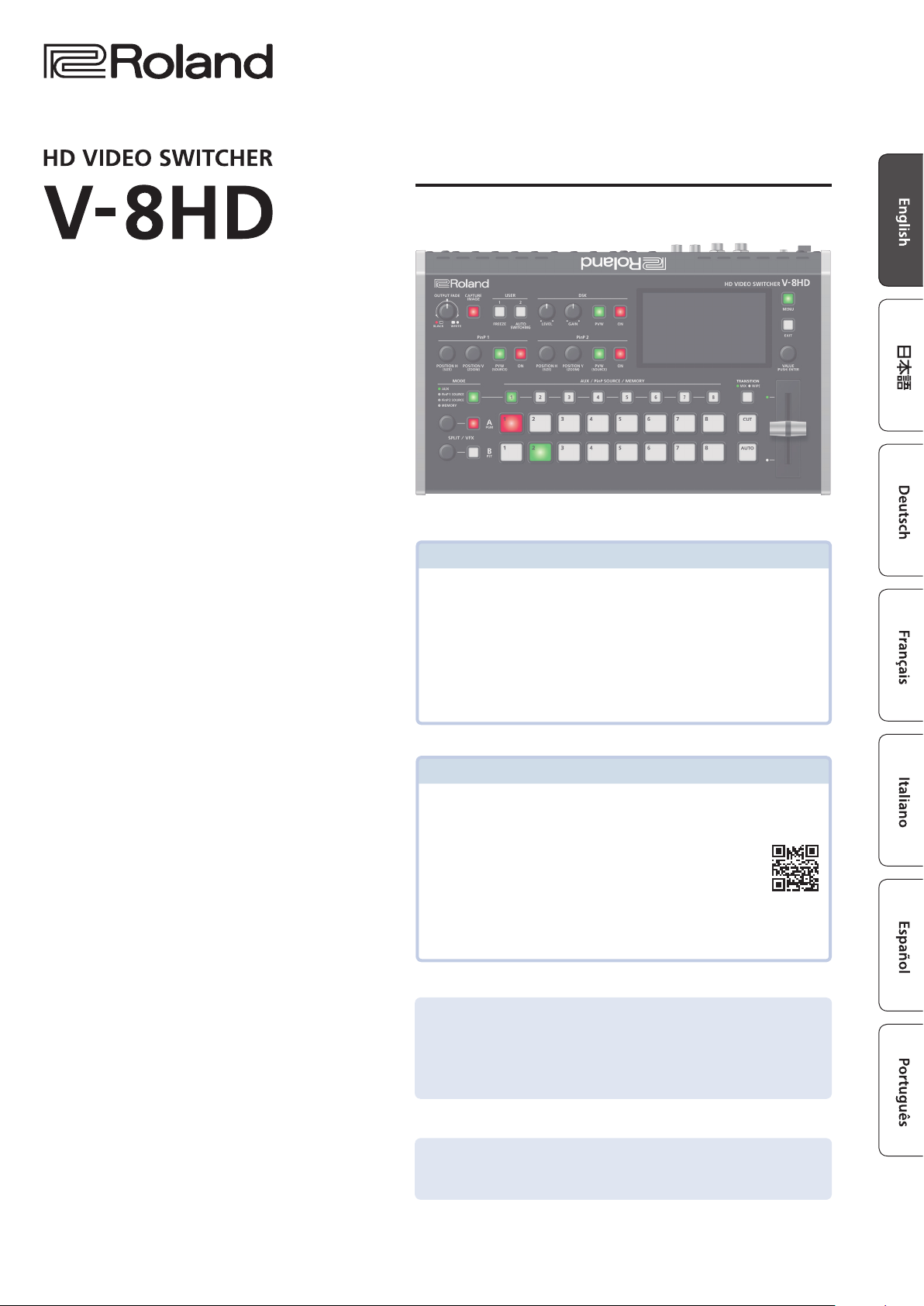
Startup Guide
Checking the Included Items
Check that all of the included items are present. If any of the included
items are missing, contact your dealer.
* V-8HD unit
* AC adaptor
* Power cord
* Startup Guide (this document)
* Leaet “USING THE UNIT SAFELY”
PDF Manual (download from the Web)
Details on operations and menu lists are provided in
“Reference Manual” (PDF).
Downloading
1. Access the Roland website.
https://proav.roland.com
2. Move to the product page 0 click “Support” 0 download the
applicable PDF le.
Before using the unit, ensure that its system program is at the most recent version.
For information on available upgrades for the system program, see the Roland
website (https://proav.roland.com/).
You can check the system program version by Pressing the [MENU] button 0
“SYSTEM”0 “VERSION.”
Before using this unit, carefully read “USING THE UNIT SAFELY” and “IMPORTANT NOTES”
(leaet “USING THE UNIT SAFELY” and Startup Guide (p. 11)). After reading, keep the
document(s) where it will be available for immediate reference.
© 2020 Roland Corporation
Page 2
Panel Descriptions
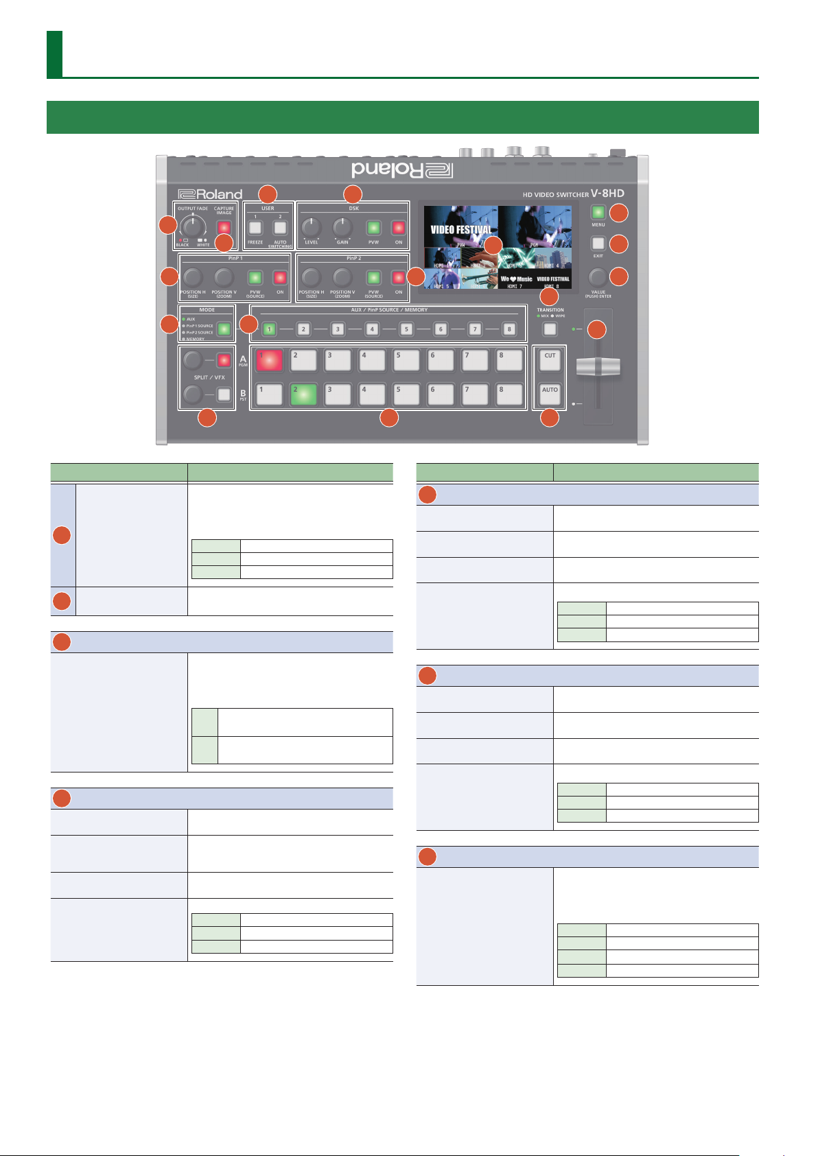
Top Panel / Side Panel
3
1
2
5
4
15
14
6
16
17
11
7 8
9 10 12
Name Explanation
The program output video and audio fade in/out.
Turning the knob toward the left fades the
output to black, and turning the knob toward the
[OUTPUT FADE]
1
knob
[CAPTURE IMAGE]
2
button
3
USER
[1], [2] button
4
DSK
[LEVEL] knob
[GAIN] knob
[PVW] button
[ON] button
right fades the output to white.
Lit Fade-out completed
Blink Fading in/out
Unlit Normal output
Captures a still image from the input/output
video.
Execute the functions that are assigned by the
menu settings.
With the factory settings, the following functions
are assigned.
FREEZE:
[1]
Stops (freezes) input video.
AUTO SWITCHING:
[2]
Automatically switches the input video.
During DSK compositing, this adjusts the amount
of keying (transparency).
During DSK compositing, this adjusts the degree
of edge blur (the semi-transmissive region) for
keying.
When this is on (lit), it makes the DSK
compositing results the preview output.
This switches DSK composition on or o.
Lit DSK composition on
Blink Currently switching video
Unlit DSK composition o
13
Name Explanation
5
PinP 1
[POSITION H] knob
[POSITION V] knob
[PVW] button
[ON] button
6
PinP 2
[POSITION H] knob
[POSITION V] knob
[PVW] button
[ON] button
7
MODE
[MODE] button
During PinP 1 compositing, this adjusts the
horizontal display position of the inset screen.
During PinP 1 compositing, this adjusts the
vertical display position of the inset screen.
When this is on (lit), it makes the PinP 1
compositing results the preview output.
This switches PinP 1 composition on or o.
Lit PinP 1 composition on
Blink Currently switching video
Unlit PinP 1 composition o
During PinP 2 compositing, this adjusts the
horizontal display position of the inset screen.
During PinP 2 compositing, this adjusts the
vertical display position of the inset screen.
When this is on (lit), it makes the PinP 2
compositing results the preview output.
This switches PinP 2 composition on or o.
Lit PinP 2 composition on
Blink Currently switching video
Unlit PinP 2 composition o
This switches the functioning of the AUX / PinP
SOURCE / MEMORY [1]–[8] buttons.
The lit color of the button indicates the function
that is selected.
Green AUX
Yellow PinP1 SOURCE
Magenta PinP2 SOURCE
Blue MEMORY
2
Page 3
Panel Descriptions
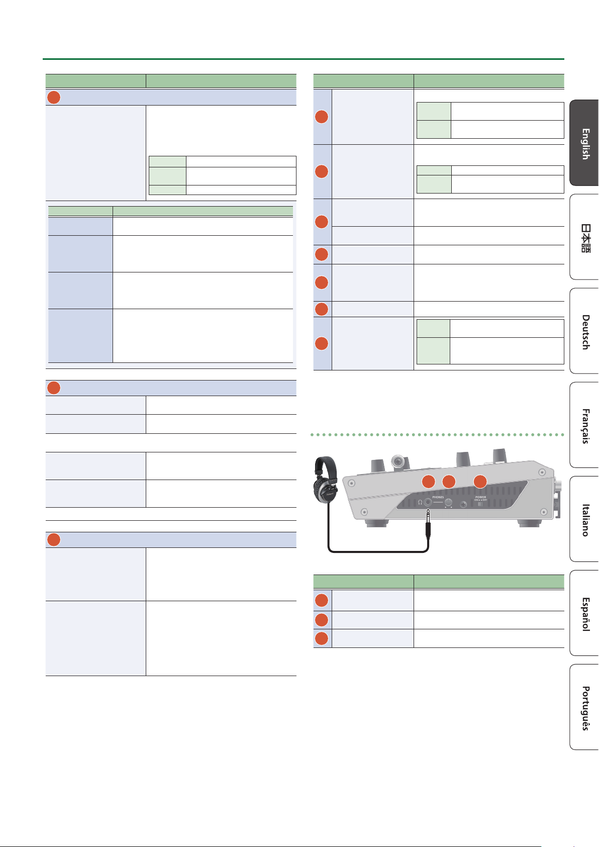
Name Explanation
8
AUX / PinP SOURCE / MEMORY
Select the object of operation according to the
function selected by the [MODE] button.
The selected button lights up in red.
The respective buttons also function as indicators
[1]–[8] buttons
[MODE] button Explanation
AUX
PinP1 SOURCE
PinP2 SOURCE
MEMORY
The buttons function as AUX-bus selection buttons. They
select the video (channel 1–8) to send to the AUX bus.
The buttons function as source screen select buttons for
PinP 1.
The buttons select the video (channels 1–8) that is shown
in the inset screen of PinP 1.
The buttons function as source screen select buttons for
PinP 2.
The buttons select the video (channels 1–8) that is shown
in the inset screen of PinP 2.
The buttons function as preset-memory selection buttons.
These save video and audio settings, the state of the
operation panel, and other current settings, and call up
settings saved in memory.
Press this button to recall settings; long-press this button
to save settings.
showing the input status of the video.
Lit white Valid video is being input.
Blink white
Unlit No video is input.
Video whose format diers from the
system format setting is input.
Name Explanation
Selects the video transition eects.
[TRANSITION]
11
button
[CUT] button
12
[AUTO] button
Video fader
13
Transition indicators
14
Monitor
15
[MENU] button
[EXIT] button
16
17
[VALUE] knob
MIX
WIPE
These make the preset video (the video to output
next) the nal output.
[CUT] The picture switches instantly.
[AUTO]
Manually switch between the videos being input
to bus A and B, and send them to the program
output.
The indicator for the nal-output bus end lights
up.
Shows the input/output video, a still image, or a
menu screen.
Switches between displaying or hiding the menu.
The menu appears on the built-in monitor
and the display connected to the OUTPUT 3
connector.
Returns you to the menu one level higher.
Turning
Pressing
The two pictures are blended
together as the video is switched.
The original video is broken into by
the next video.
The picture switches with a transition
eect applied.
Selects a menu item or changes a
setting value.
Accepts the selected menu item or
applies changes to a setting. It also
executes operations.
9
SPLIT / VFX A, SPLIT / VFX B
SPLIT/VFX [A] knob
SPLIT/VFX [B] knob
* By holding down the [SPLIT/VFX] button and turning the [SPLIT/VFX] knob, you
can change the type of split/visual eect.
SPLIT/VFX [A] button
SPLIT/VFX [B] button
* If the SPLIT/VFX type is set to split, it is not possible to turn both A and B on.
10
A/PGM, B/PST
Cross-point A [1]–[8]
buttons
Cross-point B [1]–[8]
buttons
Adjust the depth of the eect when split/visual
eect A is on.
Adjust the depth of the eect when split/visual
eect B is on.
If this is on (lit), the eect of split/visual eect A is
applied to the video selected by the Cross-point
A [1]–[8] buttons.
If this is on (lit), the eect of split/visual eect B is
applied to the video selected by the Cross-point
B [1]–[8] buttons.
Selects the video to input to bus A of the video
mixer.
The selected button lights up in red.
When the SPLIT/VFX [A] button is on, the split/
visual eect A eect is applied to the video.
Selects the video to input to bus B of the video
mixer.
The selected button lights up in green.
* While compositing of the video is in progress
it lit red.
When the SPLIT/VFX [B] button is on, the split/
visual eect B eect is applied to the video.
Side panel
18 19
Name Explanation
PHONES jack
18
(Stereo miniature type)
[PHONES] knob
19
[POWER] switch
20
Connect headphones.
Adjusts the volume of the headphones.
Turns the power on/o.
20
3
Page 4
Panel Descriptions
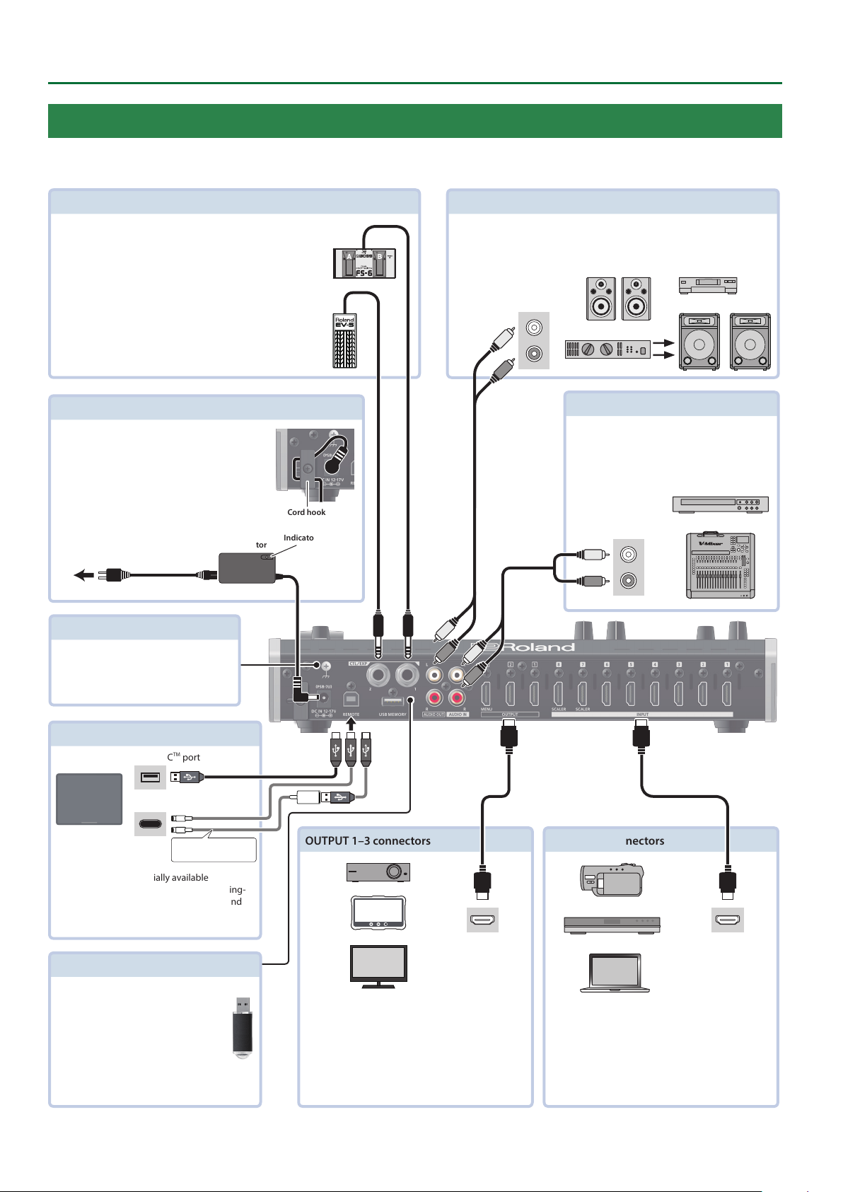
Rear Panel (Connecting Your Equipment)
* To prevent malfunction and equipment failure, always turn down the volume, and turn o all the units before making any connections.
* Be sure to use cables and adaptor plugs with the proper connectors matching those of the other devices you are using.
CTL/EXP 1, 2 jacks
Connect footswitches (sold separately: BOSS FS-6, etc.) or
expression pedals (sold separately: EV-5, etc.).
This is used when using your foot to control operations such
as video switching.
* Use only the specied expression pedal (EV-5, BOSS
FV-500L, or FV-500H sold separately). By connecting any
other expression pedals, you risk causing malfunction
and/or damage to the unit.
DC IN jack
Connect the included AC adaptor to this jack.
* Use the cord hook to secure the cord of the AC
adaptor as shown in the illustration.
Cord hook
Indicator
To AC outlet
AC adaptor
Power cord
AUDIO OUT L, R jacks
These output the results of audio mixing.
Connect them to an audio recording deck, amplier, speakers, or other such
equipment.
Audio input
connectors
AUDIO IN L, R jacks
Inputs the audio signals.
Connect an audio mixer, CD players, or other
such audio equipment.
Audio output
connectors
Ground terminal
Connect this to an external earth or
ground if necessary.
REMOTE port
USB Type-CTM port
Lightning port
Lightning-USB camera
adaptor
You can use a commercially available
connection cable or adaptor cable (Lightning-
USB camera adaptor) to connect an iPad, and
remotely control the V-8HD.
USB MEMORY port
Connect a USB ash drive to this port.
You use it when importing still images
or when saving or loading settings for
the unit.
* Never turn o the power or remove
the USB ash drive while the USB
ash drive is being accessed.
OUTPUT 1–3 connectors
HDMI input
connector
These output video.
Connect projectors, recording equipment, and
external displays.
The V-8HD menu is shown on the display that’s
*
connected to the OUTPUT 3 connector.
INPUT 1–8 connectors
HDMI output
connector
These input video.
Connect these to a video camera, video device such
as a BD player, or a computer that is equipped with
an HDMI output connector.
4
Page 5
Panel Descriptions
Turning the Power On/O
* Before turning the unit on/o, always be sure to turn the volume
down. Even with the volume turned down, you might hear some
sound when switching the unit on/o. However, this is normal and
does not indicate a malfunction.
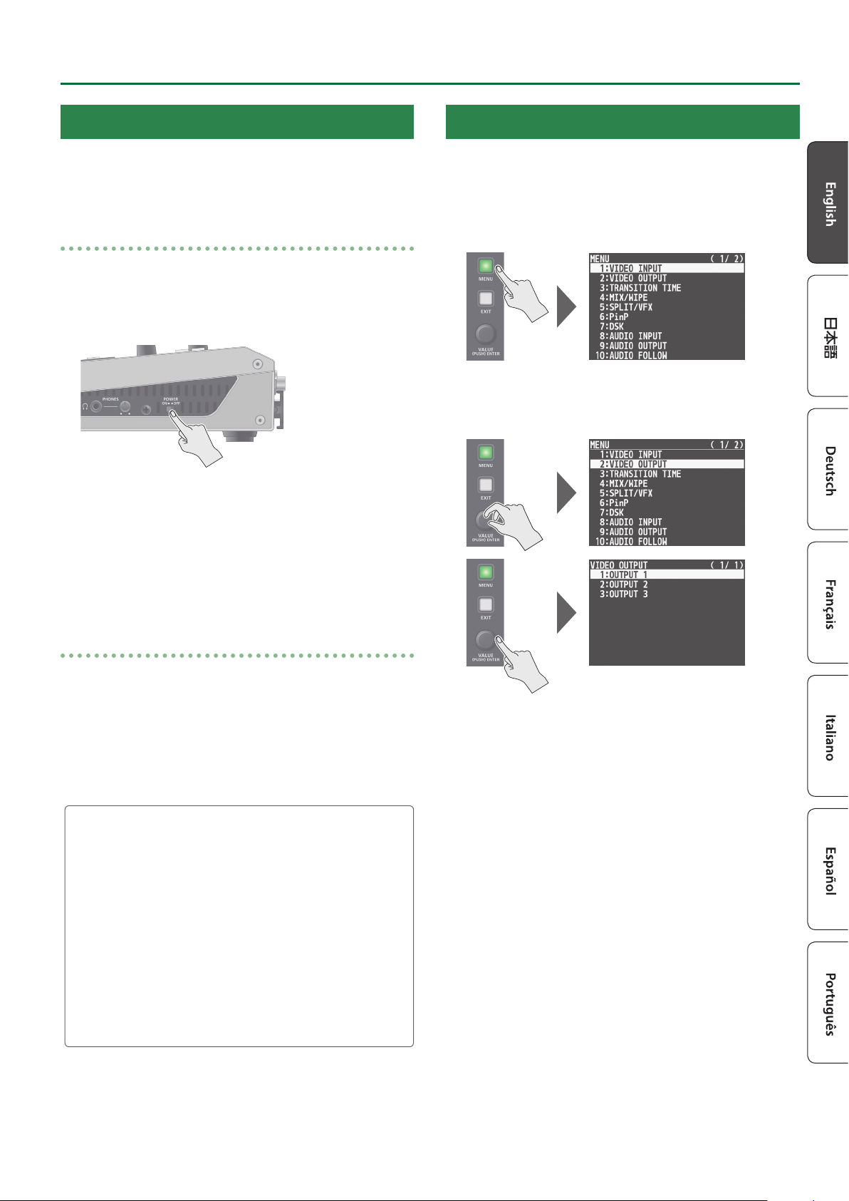
Turning the power on
1. Make sure all devices are turned o.
2. Turn on the [POWER] switch on the V-8HD to turn
on the power.
3. Turn on the power to the source devices.
Turn on the power to video cameras or other source equipment
connected to input connectors on the V-8HD.
Using the Menus
This explains how to display menus and make settings for video and
for the V-8HD itself.
* The menu is also appears on the display connected to the OUTPUT
3 connector.
1. Press the [MENU] button to display the menu.
The [MENU] button lights up, the menu categories are displayed.
2. Turn the [VALUE] knob to select a category, and
press the [VALUE] knob to conrm.
4. Turn on the power to the output devices.
Turn on the power to projectors or other devices connected to
output connectors on the V-8HD.
Turning the power o
1. Turn o the power in the sequence of rst the
output equipment, and then the sources.
2. Turn o the [POWER] switch on the V-8HD to turn
o the power.
About the Auto O function
The power to the V-8HD turns o automatically when all of the
following states persist for 240 minutes (Auto O function).
5 No operation performed on the V-8HD
5 No audio or video input
5 No equipment is connected to the OUTPUT connectors
If you do not want the power to be turned o automatically,
disengage the Auto O function. Press the [MENU] button 0
“SYSTEM” 0set “AUTO OFF” to “OFF.”
* Unsaved data is lost when the power turns o. Before turning
the power o, save the data that you want to keep.
* To restore power, turn the power on again.
The menu for the selected category is displayed.
3. Turn the [VALUE] knob to select a menu item, then
press the [VALUE] knob to conrm.
The cursor moves to the setting value.
5 If the menu item is located at a deeper level, repeat step 3.
5 Pressing the [EXIT] button moves you back one level higher.
4. Turn the [VALUE] knob to change the value of the
setting.
5 By turning the [VALUE] knob while pressing it, you can change the
value more greatly.
5 Pressing and holding the [VALUE] knob returns the current menu
item you’re setting to its default value.
5. Press the [VALUE] knob to apply the setting.
The cursor returns to the menu item.
6. Press the [MENU] button to quit the menu.
5
Page 6
Video Operations
Using Mix/Wipe to Switch the Video
Here’s how to switch between input video while applying an eect, and nal output.
About the operation mode for video transitions
There are two operation modes for switching the video on the
PGM/A bus and PST/B bus: the “PGM/PST mode” and the “A/B mode.”
* With the factory settings, the operation mode is set to A/B mode.
Mode Explanation
When the video fader is operated, the video at the
bus position toward which the video fader is ipped
A/B
PGM/PST
always becomes the nal output.
When the [CUT] or [AUTO] button is operated, the
video on the A bus and the video on the B bus
become the nal output in alternation.
The video on the PGM bus is always the nal output.
The video on the PST bus is preset video (the video to
be output next).
Operating the video fader or the [CUT] or [AUTO]
button makes the nal video output and the preset
video change places.
Switching in the A/B Mode
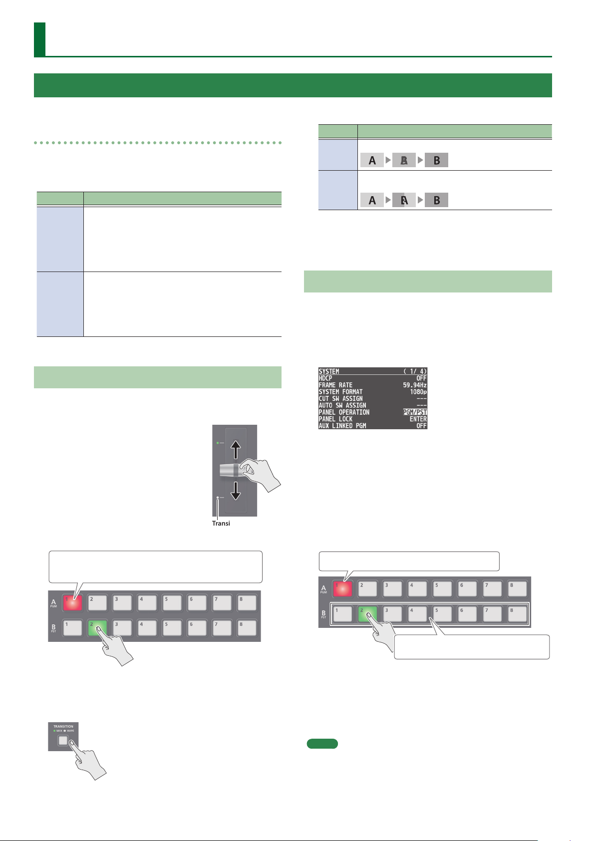
The video at the end to which the video fader is ipped is always the
nal output.
Mode Explanation
MIX
WIPE
The two videos are mixed as the transition occurs.
The next video moves across to replace the original
video.
4. Move the video fader in the direction opposite to
the direction in step 1.
The video changes.
Switching in the PGM/PST Mode
1. Press the [MENU] button0“SYSTEM”0select
“PANEL OPERATION,” and press the [VALUE] knob.
2. Turn the [VALUE] knob to select “PGM/PST,” then
press the [VALUE] knob.
1. Flip the video fader all the way
upward or downward.
2. Press a Cross-point [1]–[8] button
at the end to which the video
fader is not ipped to select the
preset video (the video to output
next).
Lit red: Final output video
Lit green: Preset video (the video to be output next)
The preset video appears in the PVW section of the monitor.
Transition indicator
3. Press the [TRANSITION] button to select the
transition eect.
3. Press the [MENU] button to quit the menu.
4. Flip the video fader all the way upward or
downward.
5. Press the [TRANSITION] button to select the
transition eect.
6. Press a Cross-point B [1]–[8] button to select the
preset video (the video to be output next).
Lit red: Final output video
Lit green:
Preset video (the video to be output next)
7. Move the video fader in the direction opposite to
the direction in step 4.
The video changes.
When the video has switched completely, the illuminated state of
the A [1]–[8] buttons and B [1]–[8] buttons is exchanged.
The MIX or WIPE indicator is lit.
6
MEMO
You can change the transition pattern used for a mix or wipe. For
details, please refer to “Reference Manual” (PDF).
Page 7
Compositing Video with Split (SPLIT)
This composites two video streams in a split screen.
The nal output video is displayed above or on the left, and the
preset video (the video to be output next) is displayed below or on
the right.
Video Operations
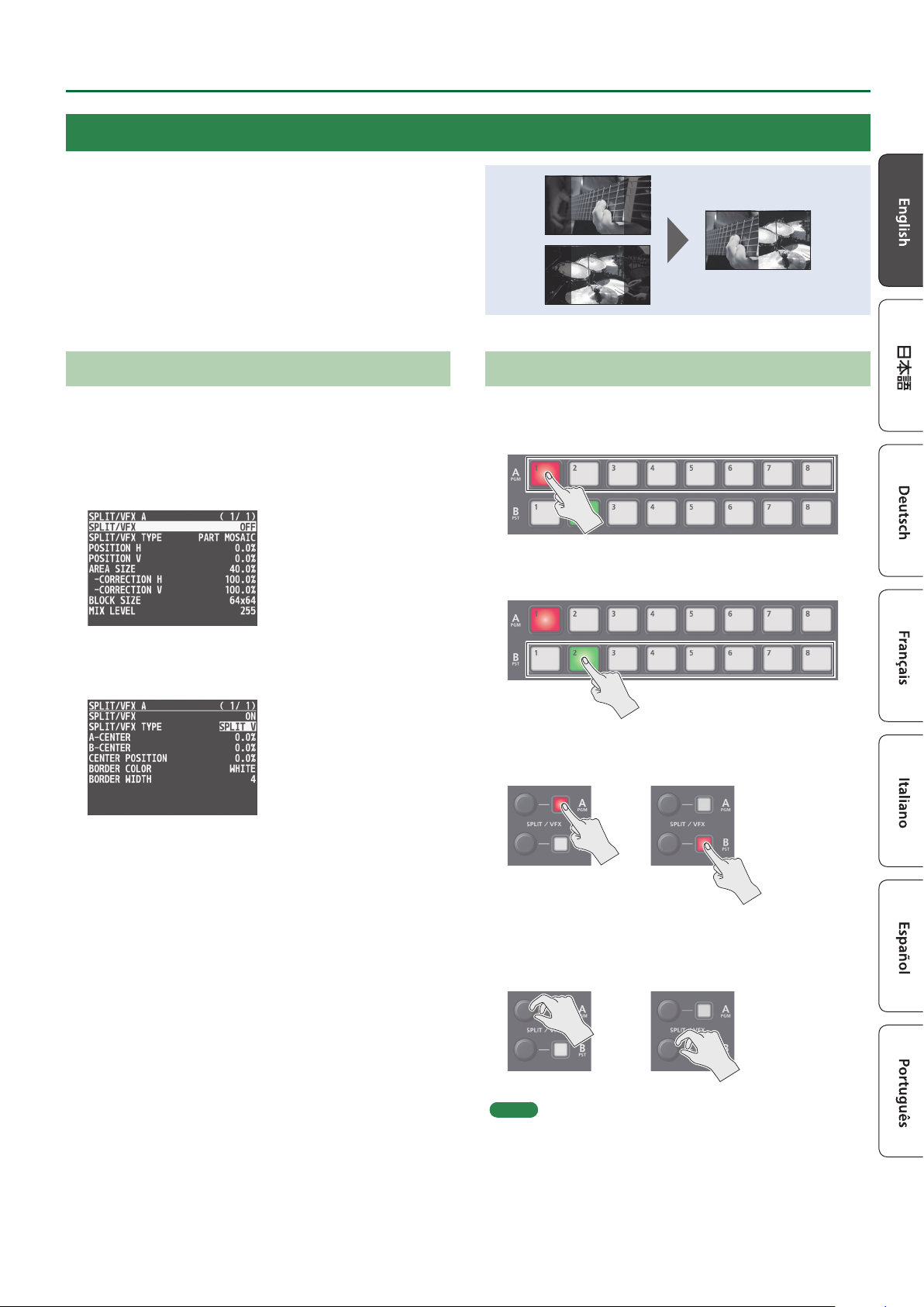
Specifying a SPLIT Composition Pattern
This makes the settings for the split composition pattern to match
the video you want to composite.
1. Press the [MENU] button0“SPLIT/VFX”0select
“SPLIT/VFX A” or “SPLIT/VFX B,” and press the
[VALUE] knob.
2. Turn the [VALUE] knob to select “SPLIT/VFX TYPE,”
then press the [VALUE] knob.
Compositing Using SPLIT
1. Press a Cross-point A [1]–[8] button to select the
video you want to display above or on the left.
2. Press a Cross-point B [1]–[8] button to select the
video you want to display below or on the right.
3. Press the SPLIT/VFX [A] or [B] button to turn on
SPLIT (lighted).
3. Turn the [VALUE] knob to select the SPLIT type,
then press the [VALUE] knob.
You can select “SPLIT H” or “SPLIT V.”
* For more about the SPLIT types and eects, refer to “Reference
Manual” (PDF).
4. Press the [MENU] button to quit the menu.
The video you selected in steps 1 and 2 is composited.
4. Turn the SPLIT/VFX [A] or [B] knob to adjust the
display position of the video.
MEMO
By turning the knob while pressing it, you can adjust the position
of the dividing line between the two videos.
5. To turn o SPLIT, press the SPLIT/VFX [A] or [B]
button once again.
7
Page 8
Video Operations
Using a Visual Eect (VFX)
Here’s how you can apply an eect to the entire video, such as varying the video’s color or shape.
You can apply a visual eect (VFX) to the A/PGM bus and B/PST bus respectively.
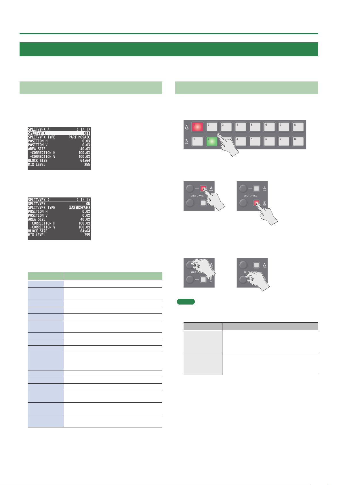
Selecting a Visual Eect
1. Press the [MENU] button0“SPLIT/VFX”0select
“SPLIT/VFX A” or “SPLIT/VFX B,” and press the
[VALUE] knob.
2. Turn the [VALUE] knob to select “SPLIT/VFX TYPE,”
then press the [VALUE] knob.
3. Turn the [VALUE] knob to select the visual eect,
then press the [VALUE] knob.
* With the factory settings, “PART MOSAIC” is specied.
Applying Visual Eects
1. Press a cross-point A or B [1]–[8] button to output
the video to which you want to apply the eect.
2. Press the SPLIT/VFX [A] or [B] button to turn on the
visual eect (making the button light up).
The visual eect is applied to the output video.
3. Turn the SPLIT/VFX [A] or [B] knob to adjust the
degree of eect applied.
Type Explanation
PART MOSAIC Applies a mosaic to the selected region.
BACKGROUND
MOSAIC
FULL MOSAIC Applies a mosaic to the entire screen.
WAVE Makes the video wavy.
RGB REPLACE Exchanges the colors.
COLORPASS
NEGATIVE Inverts the brightness and colors.
COLORIZE Adds color to the video.
POSTERIZE Changes the gradations in brightness.
SILHOUETTE
EMBOSS Adds a bas-relief eect to the video.
FIND EDGES Extracts contours.
MONOCOLOR Turns the video monochrome.
HUE OFFSET
SATURATION
OFFSET
VALUE OFFSET
Applies a mosaic to the portion outside the
selected region.
Turns the video black and white while
preserving a specic color.
Separates the video into light and dark areas,
and makes the dark areas black and adds a
dierent color to the light areas.
Changes the visual character by controlling the
hue.
Changes the visual character by controlling the
saturation.
Changes the visual character by controlling the
brightness.
4. Press the [MENU] button to quit the menu.
MEMO
5 For “PART MOSAIC” and “BACKGROUND MOSAIC,” you can adjust
the following settings.
Knob operation Explanation
Adjusts the horizontal position of the selected area.
Turning
Turn while pressing
5 Settings for the eect that is controlled by the SPLIT/VFX [A] or [B]
knobs can be checked in the VFX menu.
5 By holding down the SPLIT/VFX [A] ([B]) button and turning the
SPLIT/VFX [A] ([B]) knob, you can change the type of visual eect.
While pressing an A or B [1]–[8] button:
Adjusts the size of the selected area.
Adjusts the vertical position of the selected area.
While pressing an A or B [1]–[8] button:
Species the neness (block size) of the mosaic.
4. To turn o a visual eect, press the SPLIT/VFX [A] or
[B] button once again.
8
Page 9
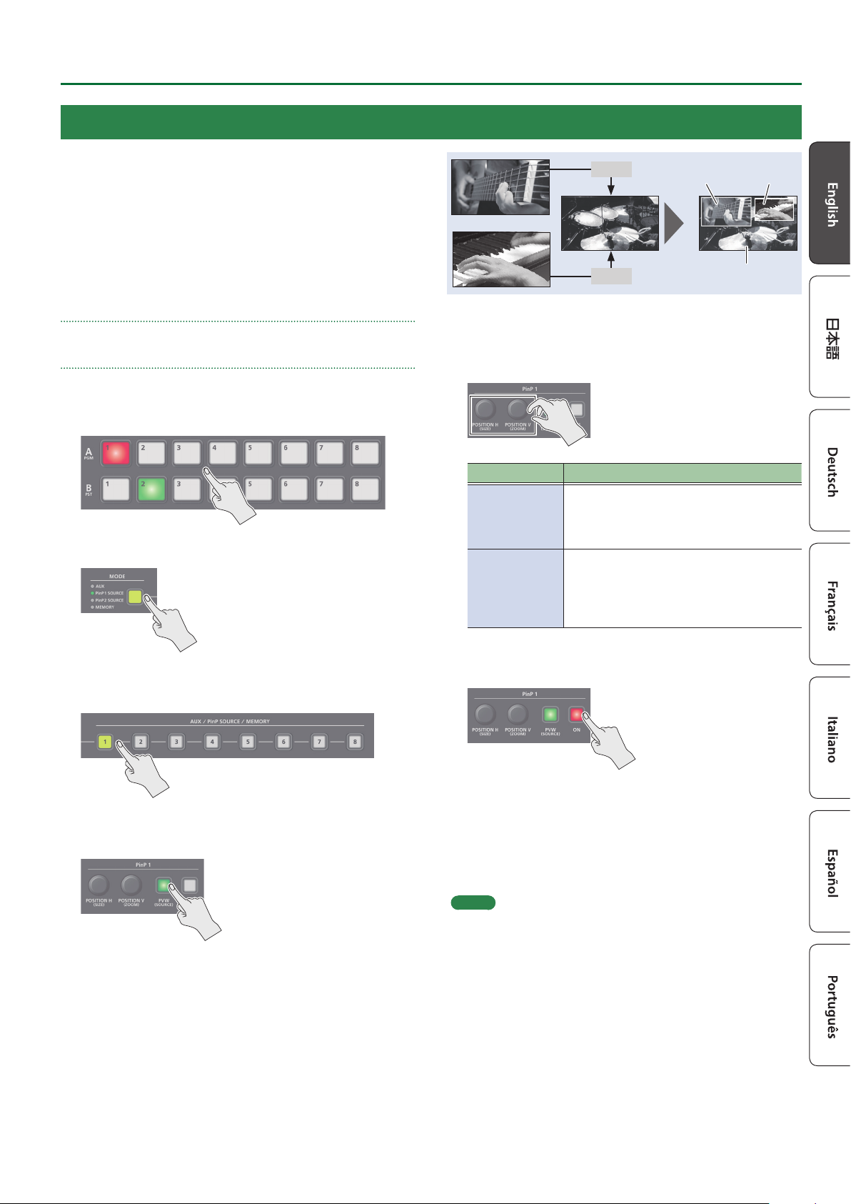
Compositing Video with Picture-in-Picture (PinP)
Video Operations
Here’s how to composite an inset screen (a small separate screen)
onto the background video.
You can use PinP 1 and PinP 2 simultaneously to composite two inset
screens.
Here we explain the procedure for compositing video using “PinP
1.” You can also composite video using the same procedure using
“PinP 2.”
1. Press a Cross-point A or B [1]–[8] button to select
the video you want to make the background video.
2. Press the [MODE] button to select “PinP1 SOURCE.”
PinP 1
PinP 2
Inset screen 1
(PinP 1)
Inset screen 2
(PinP 2)
Background video
5. Use the PinP 1 [POSITION H] and [POSITION V]
knobs to adjust the display position of the inset
screen.
Knob Explanation
Adjusts the inset screen’s display position
[POSITION H]
[POSITION V]
horizontally.
Turn while pressing:
Adjusts the size of the inset screen.
Adjusts the inset screen’s display position
vertically.
Turn while pressing:
Adjusts the zoom of the video shown in the
inset screen.
3. Press a PinP SOURCE [1]–[8] button to select the
video you want to make the inset screen.
4. Press the PinP 1 [PVW] button to preview-output
the video of the inset screen.
The PinP 1 [PVW] button lights up in green and the inset screen
appears in the PVW section of the monitor, allowing you to check
the inset screen’s location and size.
At this stage, the nal output has not yet been changed.
6. Press the PinP 1 [ON] button to turn on PinP
compositing (lit).
The PinP 1 [ON] button lights up in red, and the inset screen is
composited onto the background video and the result is sent to
nal output.
7. To turn o PinP compositing, press the PinP 1 [ON]
button once again.
MEMO
5 By long-pressing the PinP 1 (2) [PVW] button, you can access
the mode for selecting the inset screen without having to press
the [MODE] button and then select “PinP1 SOURCE” or “PinP2
SOURCE.”
While pressing the PinP 1 (2) [PVW] button, press a PinP SOURCE
[1]–[8] button to select the video that you want to use as the inset
screen.
5 The fade time over which the inset screen appears or disappears
when you press the [ON] button is specied by the setting of the
TRANSITION TIME menu item “PinP 1 TIME” or “PinP 2 TIME.”
5 Detailed settings for size, shape, and border width etc. can be
made for the PinP 1 and PinP 2 child screens respectively.
For details, refer to “Reference Manual” (PDF).
9
Page 10
Video Operations
Compositing Video with Downstream Keyer (DSK)
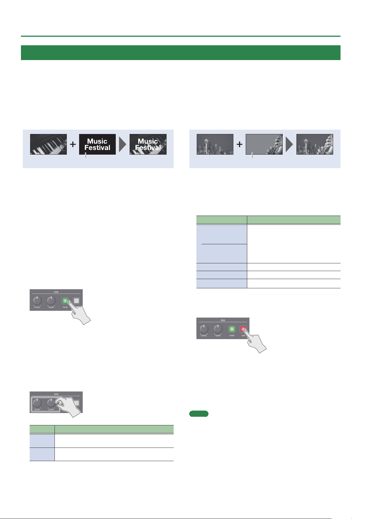
You can turn a portion of the video transparent and composite it with the background video. You can use luminance key with either a black or a
white background, or a chroma key with either a blue or green background.
You can additionally composite a variety of text and images with video that was composited using PinP or another method.
Luminance key
This cuts out text or an image by turning the black or white portion
transparent, and composites it onto the background video.
Black or white
1. Input the logo or image.
By factory default, the settings are such that text and image input
on channel 8 are used in DSK composition.
When you want to use text or image on another channel, use the
[MENU] button0“DSK”0 “DSK SOURCE” to change the channel.
When you want to composite a still image saved in the unit, set
this to “STILL 1–8.”
2. Output the background video.
At the PVW section of the monitor, check the video to be made
the background.
3. Press the DSK [PVW] button to turn on the preview
output (lit).
Chroma key
This cuts out a video by turning the blue or green portion
transparent, and composites it onto the background video. Using
this, you can composite only a subject that you are photographing
against a blue screen or green screen.
Blue or green
5. Modifying the logo or image.
When using key compositing, you can ll-in the superimposed
logo or image, or add an edge to it. Make these settings in the
following DSK menu.
Menu item Explanation
FILL TYPE
MATTE COLOR
EDGE TYPE Species the type of edge.
EDGE COLOR Species the color of the edge.
EDGE WIDTH Species the width of the edge.
If this is set to “MATTE,” the superimposed
logo or image is lled-in with the
specied color.
MATTE COLOR The ll-in color is specied
by “MATTE COLOR.”
The DSK [PVW] button lights up in green, and a preview of
the composition results is displayed in the PVW section of the
monitor.
At this stage, the nal output has not yet been changed.
4. Turn the DSK [LEVEL] and [GAIN] knob to adjust the
degree of eect applied.
Knob Explanation
[LEVEL]
[GAIN]
Adjusts the degree of extraction (transparency) for
the key.
Adjusts the degree of edge blur (semi-transmissive
region) for the key.
6. Press the DSK [ON] button to turn on DSK
composition (lit).
The DSK [ON] button lights up in red, and the composition results
is sent to nal output.
7. To turn o DSK compositing, press the DSK [ON]
button once again.
MEMO
The fade time over which the logo/image appears or disappears
when you press the DSK [ON] button is specied by the setting of
the TRANSITION TIME menu item “DSK TIME.”
10
Page 11
USING THE UNIT SAFELY
WARNING
Concerning the Auto O function
The power to this unit will be turned o automatically
after a predetermined amount of time has passed
since it was last used for playing music, or its buttons
or controls were operated (Auto O function).
If you do not want the power to be turned o automatically,
disengage the Auto O function (p. 5).
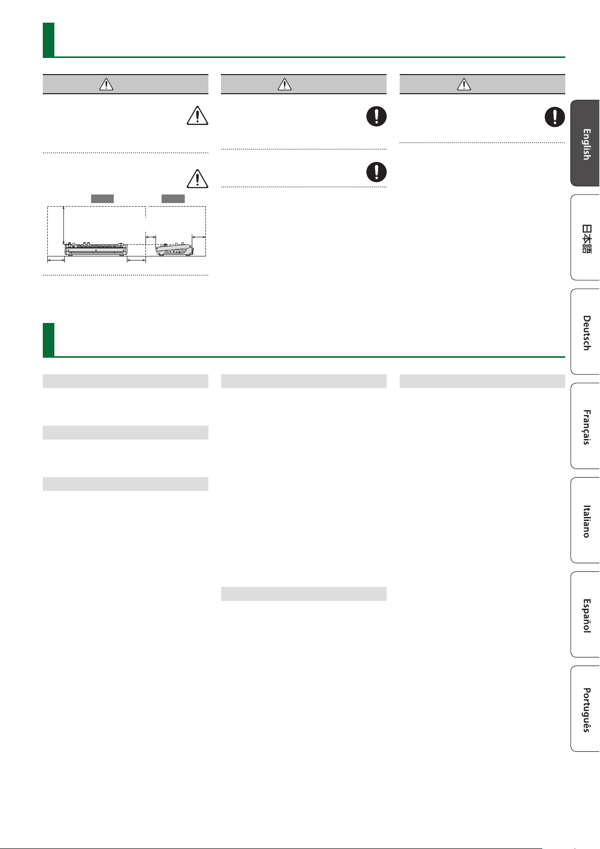
Secure a sucient amount of space at the setup location
Since this unit normally emits a slight amount of heat,
make sure to secure sucient space around it, as
shown below.
Front Side
30 cm (12 in.) or
greater
20 cm (8 in.) or greater
5 cm (2 in.) or
greater
20 cm (8 in.) or greater
15 cm (6 in.) or
greater
IMPORTANT NOTES
WARNING
Use only the supplied AC adaptor and the correct voltage
Be sure to use only the AC adaptor supplied with the
unit. Also, make sure the line voltage at the installation
matches the input voltage specied on the AC
adaptor’s body. Other AC adaptors may use a dierent
polarity, or be designed for a dierent voltage, so their use
could result in damage, malfunction, or electric shock.
Use only the supplied power cord
Use only the attached power cord. Also, the supplied
power cord must not be used with any other device.
CAUTION
Handle the ground terminal carefully
If you remove the screw from the ground terminal, be
sure to replace it; don’t leave it lying around where
it could accidentally be swallowed by small children.
When refastening the screw, make that it is rmly
fastened, so it won’t come loose.
Power Supply
• Place the AC adaptor so the side with the indicator faces
upwards. The indicator will light when you plug the AC
adaptor into an AC outlet.
Placement
• Depending on the material and temperature of the surface
on which you place the unit, its rubber feet may discolor or
mar the surface.
Repairs and Data
• Before sending the unit away for repairs, be sure to make
a backup of the data stored within it; or you may prefer to
write down the needed information. Although we will do our
utmost to preserve the data stored in your unit when we carry
out repairs, in some cases, such as when the memory section
is physically damaged, restoration of the stored content may
be impossible. Roland assumes no liability concerning the
restoration of any stored content that has been lost.
Additional Precautions
• Any data stored within the unit can be lost as the result of
equipment failure, incorrect operation, etc. To protect yourself
against the irretrievable loss of data, try to make a habit of
creating regular backups of the data you’ve stored in the unit.
• Roland assumes no liability concerning the restoration of any
stored content that has been lost.
• Never strike or apply strong pressure to the display.
• Use only the specied expression pedal. By connecting any
other expression pedals, you risk causing malfunction and/or
damage to the unit.
• This unit allows you to switch images at high speed. For some
people, viewing such images can cause headache, nausea,
or other discomfort. Do not use this unit to create video
that might cause these types of health problems. Roland
Corporation will accept no responsibility for any such health
problems that may occur in yourself or in viewers.
• Do not use connection cables that contain a built-in resistor.
• This document explains the specications of the product
at the time that the document was issued. For the latest
information, refer to the Roland website.
Using External Memories
• Please observe the following precautions when handling
external memory devices. Also, make sure to carefully observe
all the precautions that were supplied with the external
memory device.
• Do not remove the device while reading/writing is in
progress.
• To prevent damage from static electricity, discharge all static
electricity from your person before handling the device.
Intellectual Property Right
• It is forbidden by law to make an audio recording, video
recording, copy or revision of a third party’s copyrighted work
(musical work, video work, broadcast, live performance, or
other work), whether in whole or in part, and distribute, sell,
lease, perform or broadcast it without the permission of the
copyright owner.
• Do not use this product for purposes that could infringe on a
copyright held by a third party. We assume no responsibility
whatsoever with regard to any infringements of third-party
copyrights arising through your use of this product.
• This product can be used to record or duplicate audio or
visual material without being limited by certain technological
copy-protection measures. This is due to the fact that this
product is intended to be used for the purpose of producing
original music or video material, and is therefore designed so
that material that does not infringe copyrights belonging to
others (for example, your own original works) can be recorded
or duplicated freely.
• This product contains eParts integrated software platform of
eSOL Co.,Ltd. eParts is a trademark of eSOL Co., Ltd. in Japan.
• Roland and BOSS are either registered trademarks or
trademarks of Roland Corporation in the United States and/
or other countries.
• Company names and product names appearing in this
document are registered trademarks or trademarks of their
respective owners.
11
Page 12

 Loading...