

Page 1
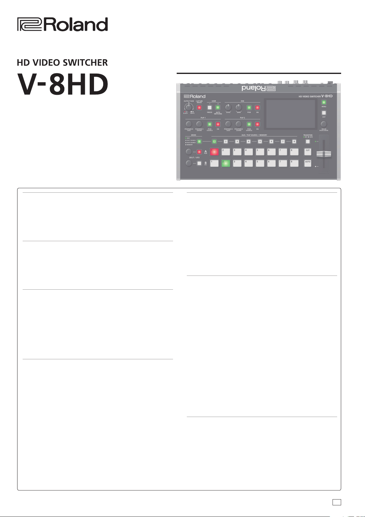
Reference Manual
Panel Descriptions ...................................... 2
Top Panel / Side Panel ..................................... 2
Rear Panel (Connecting Your Equipment) .................. 4
Multi-View Monitor Display ............................... 6
Turning the Power On/O ................................. 7
Using the Menus .......................................... 7
Video Input/Output Settings ........................... 8
Setting the Video Input/Output Format .................... 8
Adjusting Output Video ................................... 9
Adjusting the Input Video ................................. 9
Changing Output Bus Assignments ........................ 10
Inputting Copy-Protected (HDCP) Video ................... 10
Video Operations ....................................... 11
Switching the Video ...................................... 11
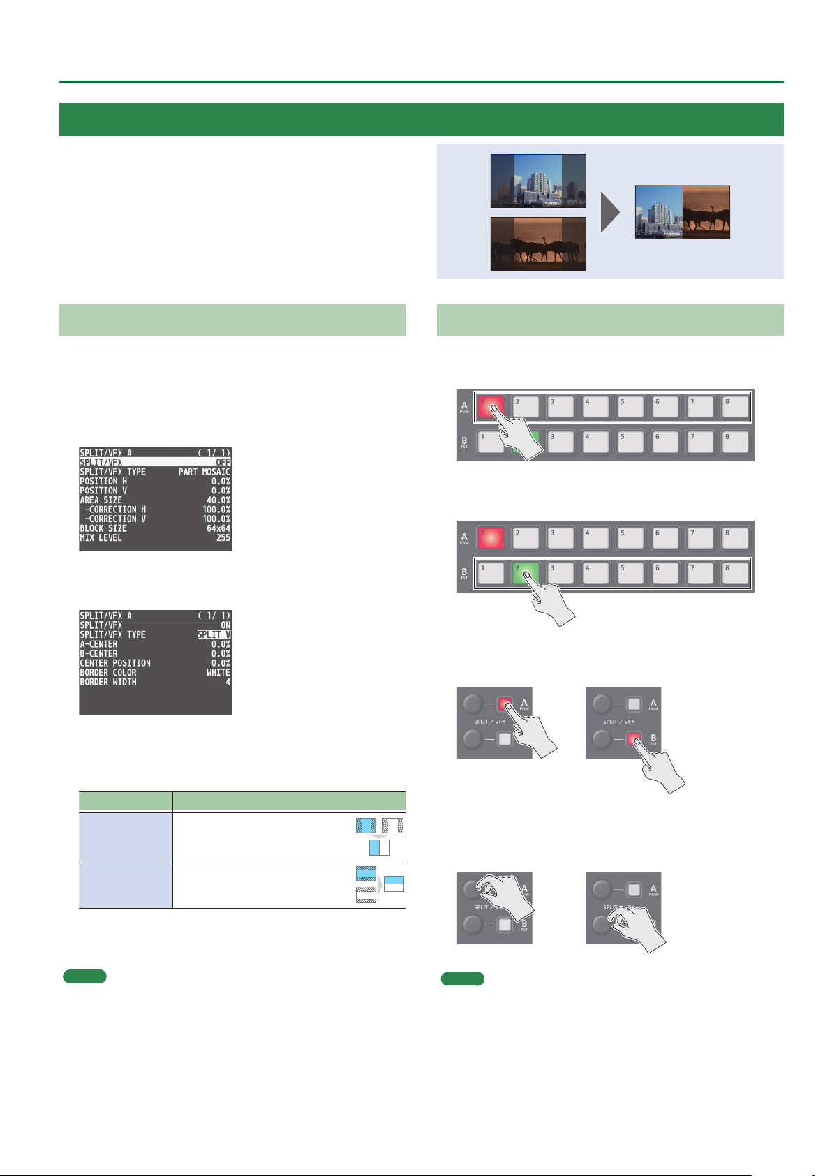
Compositing Video with Split (SPLIT) ...................... 17
Using a Visual Eect (VFX) ................................. 18
Compositing Video with Picture-in-Picture (PinP) .......... 19
Compositing Video with Downstream Keyer (DSK) ......... 22
Using Imported Still Images ............................... 26
Freezing Input Video (Freeze) ............................. 28
Applying a Fade to the Output Video (Output Fade) ........ 29
Audio Operations ....................................... 30
Adjusting the Volume Level ............................... 30
Applying Eects to Input Audio ........................... 31
Applying Eects to Output Audio ......................... 32
Silencing Only Specic Audio (Mute) ...................... 33
Interlinking Audio Output to Video Switching
(Audio Follow) ............................................ 34
Checking a Specic Audio Input (Solo) ..................... 35
Outputting AUX-Bus Audio. . . . . . . . . . . . . . . . . . . . . . . . . . . . . . . . 35
Sending the AUDIO IN Audio to the AUX Bus ............... 36
Specifying the Type of Audio Sent to the AUX Bus .......... 36
Other Features .......................................... 37
Saving/Recalling Settings (Preset Memory) ................ 37
Saving the Unit’s Settings on a USB Flash Drive ............ 38
Formatting USB Flash Drives .............................. 39
Using a Footswitch ....................................... 40
Using an Expression Pedal ................................ 41
Assigning the Functions of the USER [1] [2] Buttons ........ 42
Preventing Unintended Operation (Panel Lock) ............ 43
Controlling an External Recorder’s Video Record Start/Stop
from the V-8HD ........................................... 43
Returning to the Factory Settings (Factory Reset) .......... 44
Menu List ................................................ 45
1: VIDEO INPUT ........................................... 45
2: VIDEO OUTPUT ......................................... 46
3: TRANSITION TIME ...................................... 47
4: MIX/WIPE .............................................. 47
5: SPLIT/VFX .............................................. 48
6: PinP. . . . . . . . . . . . . . . . . . . . . . . . . . . . . . . . . . . . . . . . . . . . . . . . . . . . 52
7: DSK .................................................... 55
8: AUDIO INPUT ........................................... 56
9: AUDIO OUTPUT ........................................ 58
10: AUDIO FOLLOW ....................................... 59
11: PRESET MEMORY ...................................... 60
12: STILL IMAGE .......................................... 60
13: FREEZE ............................................... 61
14: AUTO SWITCHING ..................................... 61
15: CTL/EXP .............................................. 63
16: USB MEMORY ......................................... 64
17: SYSTEM ............................................... 65
List of Shortcut Keys ...................................... 68
Appendix ................................................ 69
Troubleshooting .......................................... 69
Main Specications ....................................... 70
Dimensions .............................................. 72
MIDI Implementation ..................................... 73
MIDI Implementation Chart ............................... 88
VIDEO Block Diagram ..................................... 89
AUDIO Block Diagram ..................................... 90
© 2020 Roland Corporation
01
Page 2
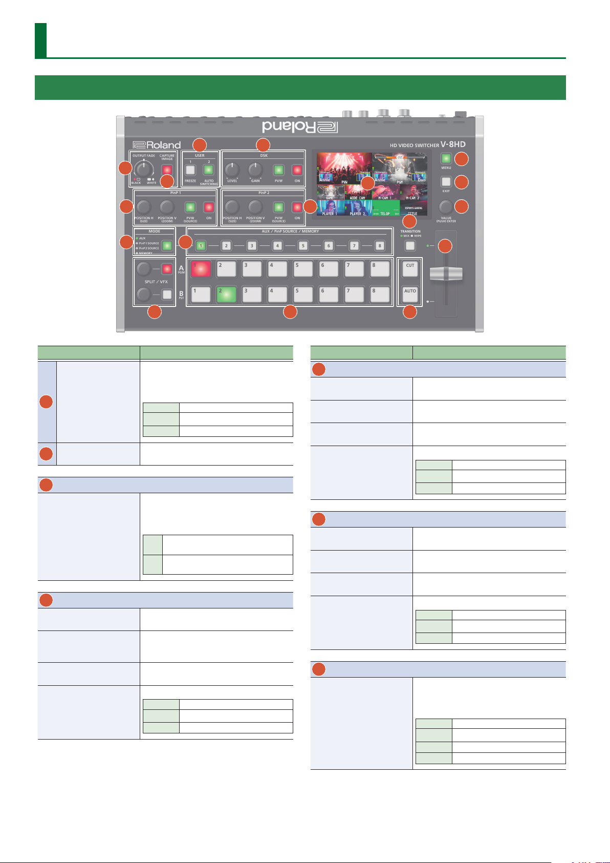
Panel Descriptions
Top Panel / Side Panel
3
1
2
5
4
15
14
6
16
17
11
7 8
9 10 12
Name Explanation
The program output video and audio fade in/out.
Turning the knob toward the left fades the
output to black, and turning the knob toward the
[OUTPUT FADE]
1
knob
[CAPTURE IMAGE]
2
button
3
USER
[1], [2] buttons
4
DSK
[LEVEL] knob
[GAIN] knob
[PVW] button
[ON] button
right fades the output to white.
Lit Fade-out completed
Blink Fading in/out
Unlit Normal output
Captures a still image from the input/output
video.
Execute the functions that are assigned by the
menu settings.
With the factory settings, the following functions
are assigned.
FREEZE:
[1]
Stops (freezes) input video.
AUTO SWITCHING:
[2]
Automatically switches the input video.
During DSK compositing, this adjusts the amount
of keying (transparency).
During DSK compositing, this adjusts the degree
of edge blur (the semi-transmissive region) for
keying.
When this is on (lit), it makes the DSK
compositing results the preview output.
Switches DSK composition on or o.
Lit DSK composition on
Blink Currently switching video
Unlit DSK composition o
13
Name Explanation
5
PinP 1
[POSITION H] knob
[POSITION V] knob
[PVW] button
[ON] button
6
PinP 2
[POSITION H] knob
[POSITION V] knob
[PVW] button
[ON] button
7
MODE
[MODE] button
During PinP 1 compositing, this adjusts the
horizontal display position of the inset screen.
During PinP 1 compositing, this adjusts the
vertical display position of the inset screen.
When this is on (lit), it makes the PinP 1
compositing results the preview output.
Switches PinP 1 composition on or o.
Lit PinP 1 composition on
Blink Currently switching video
Unlit DSK composition o
During PinP 2 compositing, this adjusts the
horizontal display position of the inset screen.
During PinP 2 compositing, this adjusts the
vertical display position of the inset screen.
When this is on (lit), it makes the PinP 2
compositing results the preview output.
Switches PinP 2 composition on or o.
Lit PinP 2 composition on
Blink Currently switching video
Unlit DSK composition o
Switches the functioning of the AUX / PinP
SOURCE / MEMORY [1]–[8] buttons.
The lit color of the button indicates the function
that is selected.
Green AUX
Yellow PinP1 SOURCE
Magenta PinP2 SOURCE
Blue MEMORY
2
Page 3
Panel Descriptions
Name Explanation
8
AUX / PinP SOURCE / MEMORY
Select the object of operation according to the
function selected by the [MODE] button.
The selected button lights up.
The respective buttons also function as indicators
showing the input status of the video.
[1]–[8] buttons
[MODE] button Explanation
AUX
PinP1 SOURCE
PinP2 SOURCE
MEMORY
The buttons function as AUX-bus selection buttons.
They select the video (channel 1–8) to send to the AUX bus.
The buttons function as source screen select buttons for
PinP 1.
The buttons select the video (channels 1–8) that is shown
in the inset screen of PinP 1.
The buttons function as source screen select buttons for
PinP 2.
The buttons select the video (channels 1–8) that is shown
in the inset screen of PinP 2.
The buttons function as preset-memory selection buttons.
These save video and audio settings, the state of the
operation panel, and other current settings, and call up
settings saved in memory.
Press this button to recall settings; long-press this button
to save settings.
Lit white Valid video is being input.
Blink white
Unlit No video is input.
Video whose format diers from the
system format setting is input.
Name Explanation
Selects the video transition eects.
[TRANSITION]
11
button
[CUT] button
12
[AUTO] button
Video fader
13
Transition indicators
14
Monitor
15
[MENU] button
[EXIT] button
16
17
[VALUE] knob
MIX
WIPE
These make the preset video (the video to output
next) the nal output.
[CUT] The picture switches instantly.
[AUTO]
Manually switch between the videos being input
to bus A and B, and send them to the program
output.
The indicator for the nal-output bus end lights
up.
Shows the input/output video, a still image, or a
menu screen.
Switches between displaying or hiding the menu.
The menu appears on the built-in monitor
and the display connected to the OUTPUT 3
connector.
Returns you to the menu one level higher.
Turning
Pressing
The two pictures are blended
together as the video is switched.
The original video is broken into by
the next video.
The picture switches with a transition
eect applied.
Selects a menu item or changes a
setting value.
Accepts the selected menu item or
applies changes to a setting. It also
executes operations.
9
SPLIT / VFX A, SPLIT / VFX B
SPLIT/VFX [A] knob
SPLIT/VFX [B] knob
* By holding down the SPLIT/VFX button and turning the SPLIT/VFX knob, you can
change the type of split/visual eect.
SPLIT/VFX [A] button
SPLIT/VFX [B] button
* If the SPLIT/VFX type is set to split, it is not possible to turn both A and B on.
10
A/PGM, B/PST
Cross-point A [1]–[8]
Adjust the depth of the eect when split/visual
eect A is on.
Adjust the depth of the eect when split/visual
eect B is on.
If this is on (lit), the eect of split/visual eect A is
applied to the video selected by the Cross-point
A [1]–[8] buttons.
If this is on (lit), the eect of split/visual eect B is
applied to the video selected by the Cross-point
B [1]–[8] buttons.
Selects the video to input to bus A of the video
mixer.
The selected button lights up.
buttons
When the SPLIT/VFX [A] button is on, the split/
visual eect A eect is applied to the video.
Selects the video to input to bus B of the video
mixer.
The selected button lights up.
Cross-point B [1]–[8]
buttons
* While compositing of the video is in progress
it lit red.
Side panel
18 19
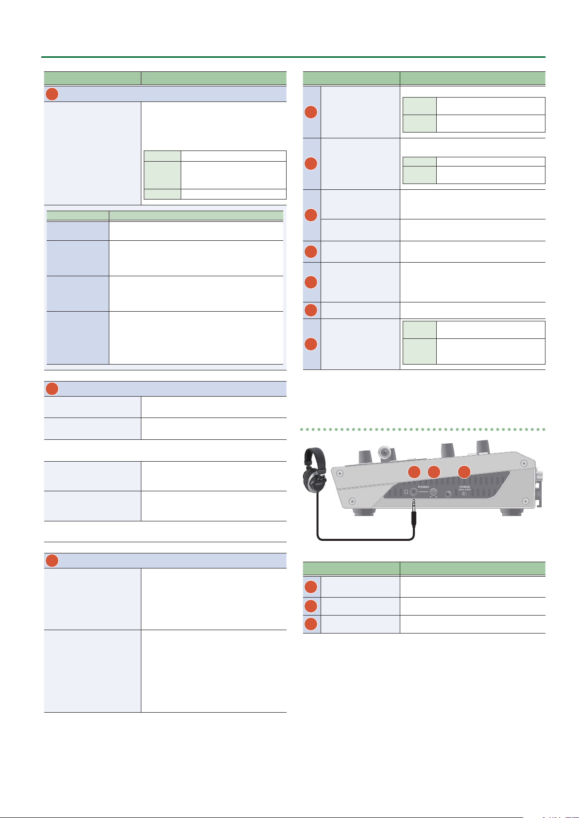
Name Explanation
PHONES jack
18
(Stereo miniature type)
[PHONES] knob
19
[POWER] switch
20
Connect headphones here.
Adjusts the volume of the headphones.
Turns the power on/o.
20
When the SPLIT/VFX [B] button is on, the split/
visual eect B eect is applied to the video.
3
Page 4
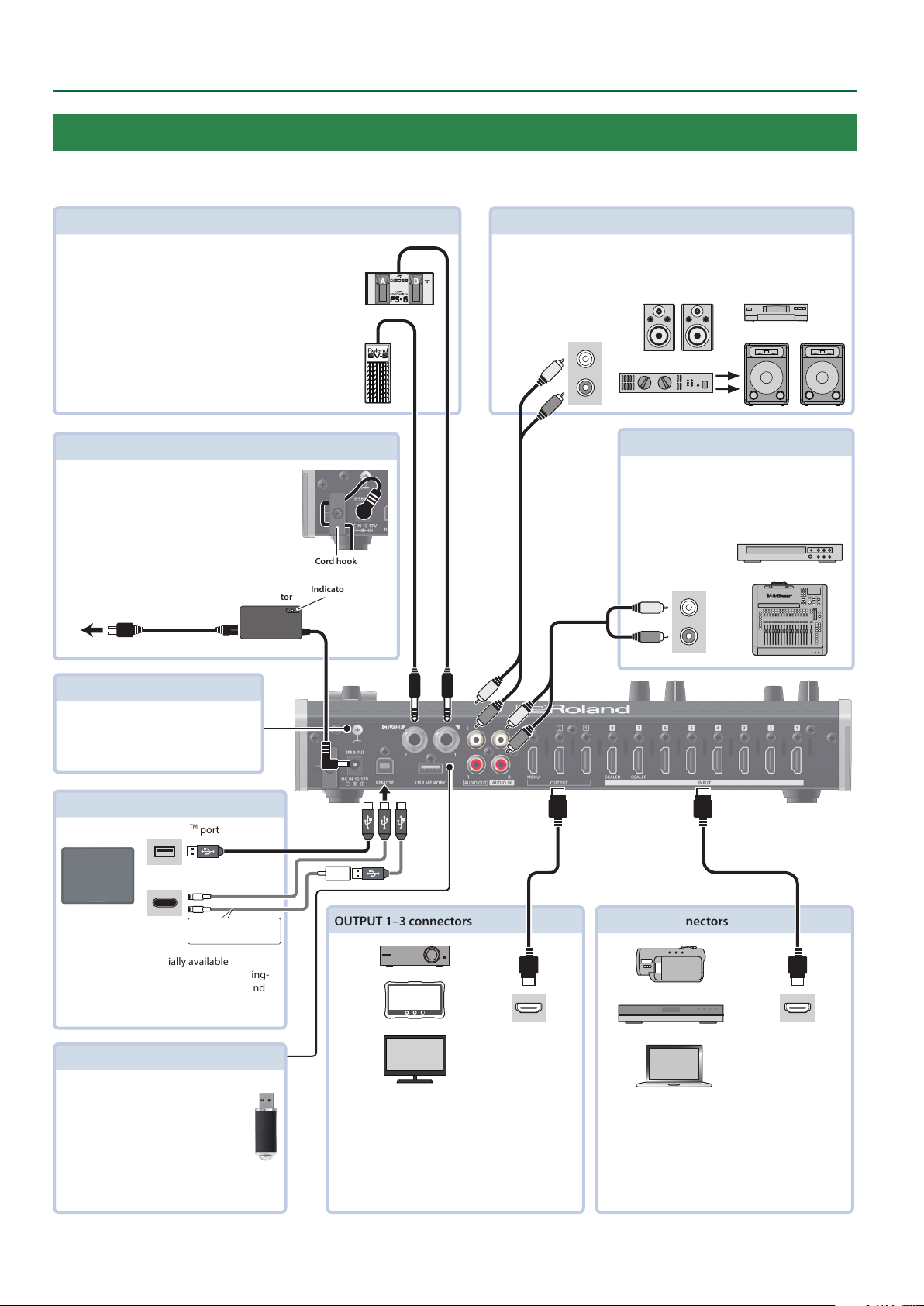
Panel Descriptions
Rear Panel (Connecting Your Equipment)
* To prevent malfunction and equipment failure, always turn down the volume, and turn o all the units before making any connections.
* Be sure to use cables and adaptor plugs with the proper connectors matching those of the other devices you are using.
CTL/EXP 1, 2 jacks
Connect footswitches (sold separately: BOSS FS-6, etc.) or
expression pedals (sold separately: EV-5, etc.).
This is used when using your foot to control operations such
as video switching.
* Use only the specied expression pedal (EV-5, BOSS
FV-500L, or FV-500H sold separately). By connecting any
other expression pedals, you risk causing malfunction
and/or damage to the unit.
DC IN jack
Connect the included AC adaptor to this jack.
* Use the cord hook to secure the cord of the AC
adaptor as shown in the illustration.
Cord hook
Indicator
To AC outlet
AC adaptor
Power cord
AUDIO OUT L, R jacks
These output the results of audio mixing.
Connect them to an audio recording deck, amplier, speakers, or other such
equipment.
Audio input
connectors
AUDIO IN L, R jacks
Inputs the audio signals.
Connect an audio mixer, CD players, or other
such audio equipment.
Audio output
connectors
Ground terminal
Connect this to an external earth or
ground if necessary.
REMOTE port
USB Type-CTM port
Lightning port
Lightning-USB camera
adaptor
You can use a commercially available
connection cable or adaptor cable (Lightning-
USB camera adaptor) to connect an iPad, and
remotely control the V-8HD.
USB MEMORY port
Connect a USB ash drive to this port.
You use it when importing still images
or when saving or loading settings for
the unit.
* Never turn o the power or remove
the USB ash drive while the USB
ash drive is being accessed.
OUTPUT 1–3 connectors
HDMI input
connector
These output video.
Connect projectors, recording equipment, and
external displays.
The V-8HD menu is shown on the display that’s
*
connected to the OUTPUT 3 connector.
INPUT 1–8 connectors
HDMI output
connector
These input video.
Connect these to a video camera, video device such
as a BD player, or a computer that is equipped with
an HDMI output connector.
4
Page 5
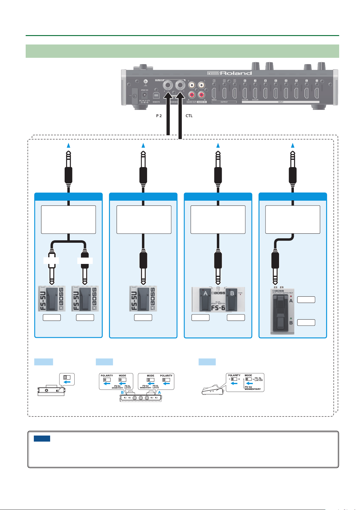
Connecting a Footswitch
Panel Descriptions
CTL/EXP 1CTL/EXP 2
FS-5U x 2
Stereo 1/4” phone type
TIP
.
/
1/4” phone type x 2
RING
CTL BCTL A
FS-5U x 1
1/4” phone type
.
/
1/4” phone type
CTL B
Stereo 1/4” phone type
Stereo 1/4” phone type
MODE/POLARITY switch
FS-5U FS-6 FS-7
FS-6
.
/
FS-7
Stereo 1/4” phone type
.
/
Stereo 1/4” phone type
CTL A
CTL BCTL A
CTL B
NOTE
The BOSS FS-6’s A, B, and A&B jacks also act as the power switch. The power turns on when you insert a plug into the jack, and turns o when
you remove the plug.
To prevent the batteries from running down, remove the plugs from the jacks when you’re not using the BOSS FS-6.
5
Page 6
Panel Descriptions
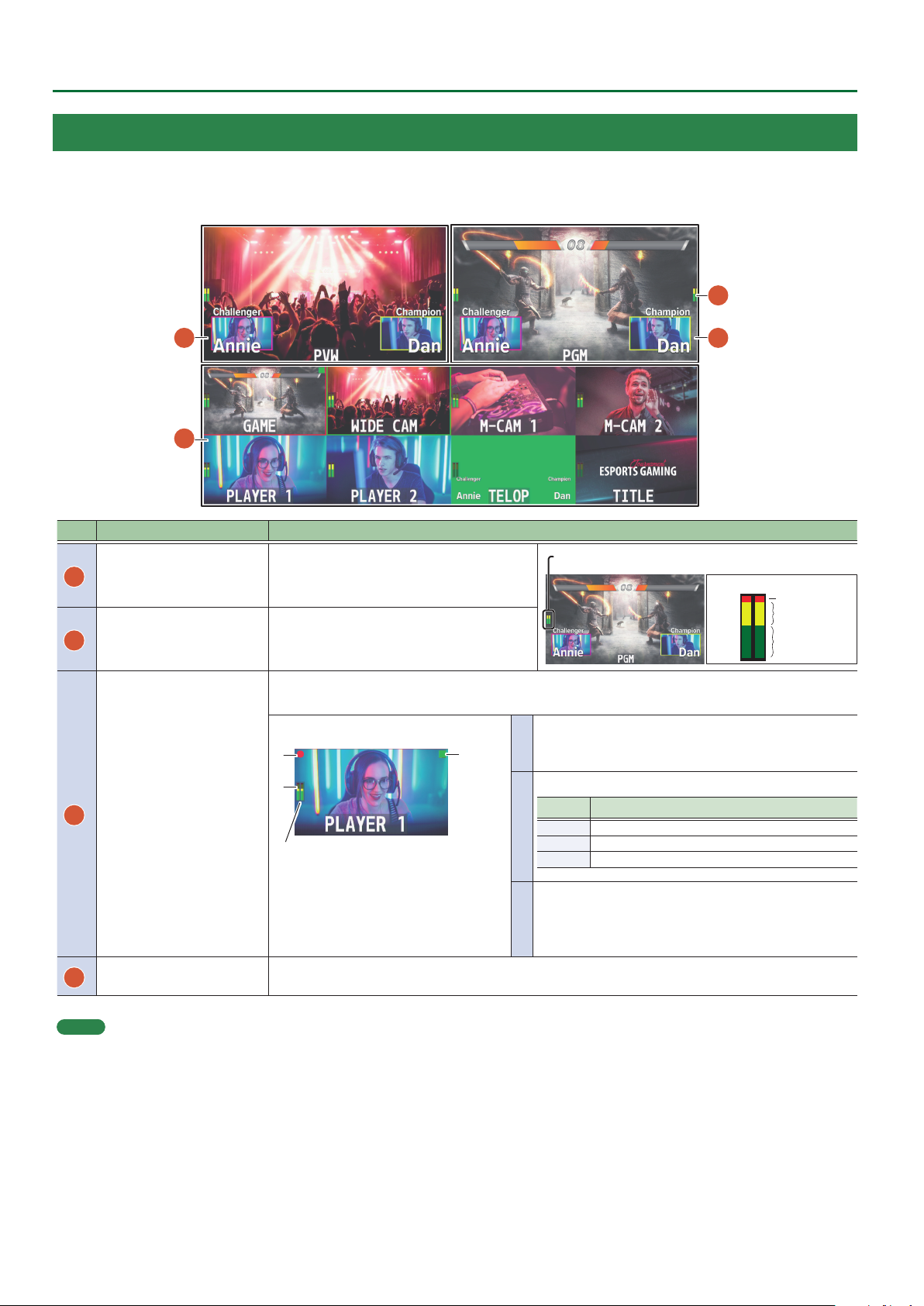
Multi-View Monitor Display
This unit’s monitor shows a list of the input/output video (nal output, preview output, input channels 1–8), a level meter, and a menu.
If you press the [MENU] button, the menu is shown overlaid on the multi-view.
4
1
3
2
No. Name Explanation
PVW (preview) section
1
PGM (program) section Displays the nal output video.
2
Displays the preset video (the video to be
output next).
Displays video input via channels 1–8.
The nal video output and preset video (the video to be output next) are displayed with tally frames.
Channel information
3
1
Channel section
3
When the multi-view monitor is shown on an
external display, an “MT” indication is shown when
the audio mute function (p. 33) is on.
When the audio follow function (p. 34) is on, an
“A.F” indication is shown.
* This is not shown on this unit’s display.
AUDIO IN level meter
4
The audio level meter for AUDIO IN is shown above or below.
* The indicators for the level meter are the same as for AUDIO OUT.
Displays the level meter for AUDIO OUT.
(dB)
0
-6
-20
-30
-50
Displays a audio level meter.
1
2
* The indicators for the level meter are the same as for
AUDIO OUT.
Indicates the function selected by the [MODE] button.
Indicator Explanation
Green AUX (AUX bus selected)
2
Yellow PinP 1 SOURCE (PinP 1 source screen selected)
Magenta PinP 2 SOURCE (PinP 2 source screen selected)
The REC indicator is shown.
If a camera that supports the HDMI REC TRIGGER function
3
is connected, this is shown when the camera’s REC button
is pressed.
Red (Excessive)
Yellow (Suitable)
Green
(Insucient)
MEMO
5 In the SYSTEM menu, you can specify whether the “label name,” “tally frame,” “audio level meter,” “AUX indicator,” “PinP indicator,” and “REC indicator”
are visible or hidden.
– MULTI-VIEW LABEL (label names)
– TALLY FRAME
– AUDIO LEVEL METER
AUDIO IN (AUDIO IN level meter)
5 You can edit the label name. Use the SYSTEM menu item “MULTI-VIEW LABEL EDIT” to edit the label name.
5 For details on the cameras that support the REC indicator function, refer to the Roland website.
https://proav.roland.com
– AUX/PinP INDICATOR (AUX indicator/PinP indicator)
– REC INDICATOR
6
Page 7
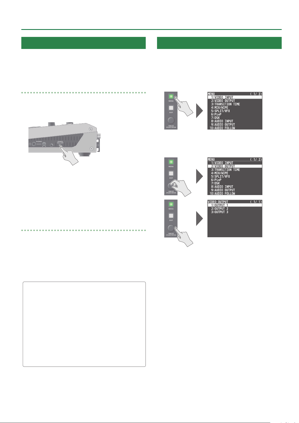
Panel Descriptions
Turning the Power On/O
* Before turning the unit on/o, always be sure to turn the volume
down. Even with the volume turned down, you might hear some
sound when switching the unit on/o. However, this is normal and
does not indicate a malfunction.
Turning the power on
1. Make sure all devices are turned o.
2. Turn on the [POWER] switch on the V-8HD to turn
on the power.
3. Turn on the power to the source devices.
Turn on the power to video cameras or other source equipment
connected to input connectors on the V-8HD.
Using the Menus
This explains how to display menus and make settings for video and
for the V-8HD itself.
* The menu is also appears on the display connected to the OUTPUT
3 connector.
1. Press the [MENU] button to display the menu.
The [MENU] button lights up, the menu categories are displayed.
2. Turn the [VALUE] knob to select a category, and
press the [VALUE] knob to conrm.
4. Turn on the power to the output devices.
Turn on the power to projectors or other devices connected to
output connectors on the V-8HD.
Turning the power o
1. Turn o the power in the sequence of rst the
output equipment, and then the sources.
2. Turn o the [POWER] switch on the V-8HD to turn
o the power.
About the Auto O function
The power to the V-8HD turns o automatically when all of the
following states persist for 240 minutes (Auto O function).
5 No operation performed on the V-8HD
5 No audio or video input
5 No equipment is connected to the OUTPUT connectors
If you do not want the power to be turned o automatically,
disengage the Auto O function. Press the [MENU] button 0
“SYSTEM” 0set “AUTO OFF” to “OFF.”
* Unsaved data is lost when the power turns o. Before turning
the power o, save the data that you want to keep.
* To restore power, turn the power on again.
The menu for the selected category is displayed.
3. Turn the [VALUE] knob to select a menu item, then
press the [VALUE] knob to conrm.
The cursor moves to the setting value.
5 If the menu item is located at a deeper level, repeat step 3.
5 Pressing the [EXIT] button moves you back one level higher.
4. Turn the [VALUE] knob to change the value of the
setting.
5 By turning the [VALUE] knob while pressing it, you can change the
value more greatly.
5 Pressing and holding the [VALUE] knob returns the current menu
item you’re setting to its default value.
5. Press the [VALUE] knob to apply the setting.
The cursor returns to the menu item.
6. Press the [MENU] button to quit the menu.
7
Page 8
Video Input/Output Settings
Setting the Video Input/Output Format
Set parameters for the input/output format to match the connected equipment.
Setting the System Format
On the V-8HD, the input/output format is determined according to
the system format. You set the input/output format to match the
connected equipment.
System
format
1080p 1080p, 1080i 1080p
1080i 1080p, 1080i 1080i
720p 720p 720p
(*1) You can specify separate individual input formats for the
channel 7 and 8 input connectors, regardless of the system
format.
For details, refer to “Setting the Input Formats for Channels 7
and 8” on this page.
(*2) The output format at the OUTPUT 3 connector is xed at “1080p.”
1. Press the [MENU] button0”SYSTEM”0select
“SYSTEM FORMAT,” and press the [VALUE] knob.
Input format (*1) Output format (*2)
INPUT 1–6 connectors OUTPUT 1–2 connectors
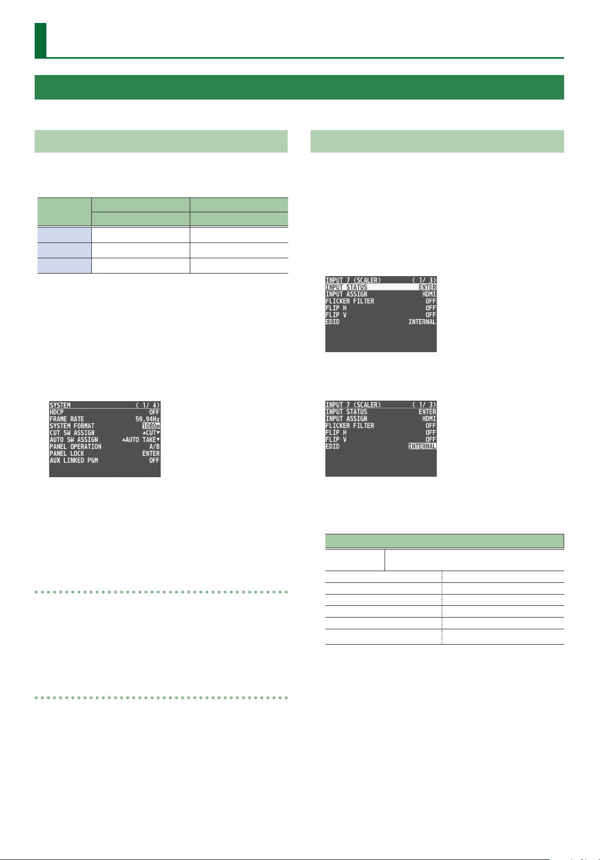
Setting the Input Formats for Channels 7 and 8
By factory default, the EDID assignment for channels 7 and 8 is
“INTERNAL” (set so that EDID values of all inputtable formats are sent).
To specify an input format of your choice, change the setting of the
EDID information being sent so that it matches the incoming video
signal.
1. Press the [MENU] button0”VIDEO INPUT”0select
“INPUT 7 (SCALER)” or “INPUT 8 (SCALER),” and press
the [VALUE] knob.
2. Turn the [VALUE] knob to select “EDID,” and press
the [VALUE] knob.
2. Turn the [VALUE] knob to set the system format to
“1080p,” “1080i,” or “720p,” and press the [VALUE]
knob.
3. Press the [MENU] button to quit the menu.
Internal processing
The V-8HD’s internal processing is progressive. Interlaced input video
is automatically converted to a progressive signal.
The picture might appear jagged at this time, or the picture in a PinP
inset screen or on the multi-view monitor might waver.
This is due to progressive conversion, and is not a malfunction.
About frame rates
To change the V-8HD’s frame rate, press the [MENU] button0
“SYSTEM”0“FRAME RATE.”
3. Turn the [VALUE] knob to set the input format (the
EDID information to send), and press the [VALUE]
knob.
Value
INTERNAL
SVGA (800x600/60Hz) UXGA (1600x1200/60Hz)
XGA (1024x768/60Hz) WUXGA (1920x1200/60Hz)
WXGA (1280x800/60Hz) 720/59.94p
FWXGA (1366x768/60Hz) 1080/59.94i
SXGA (1280x1024/60Hz) 1080/59.94p
SXGA+(1400x1050/60Hz)
EDID information for all inputtable formats is
sent.
4. Press the [MENU] button to quit the menu.
8
Page 9
Video Input/Output Settings
Adjusting Output Video
Here’s how to adjust the output image appropriately for the device
that’s receiving the V-8HD’s output.
MEMO
You can output a test pattern, useful for adjusting the image quality
of a display.
You use the [MENU] button0“SYSTEM”0“TEST PATTERN” to specify
the test pattern.
1. Press the [MENU] button0”VIDEO OUTPUT”0
select one of “OUTPUT 1” to “OUTPUT 8,” and press
the [VALUE] knob.
A menu for the selected output video appears.
2. Select a menu item, then turn the [VALUE] knob
to adjust the output video, and press the [VALUE]
knob.
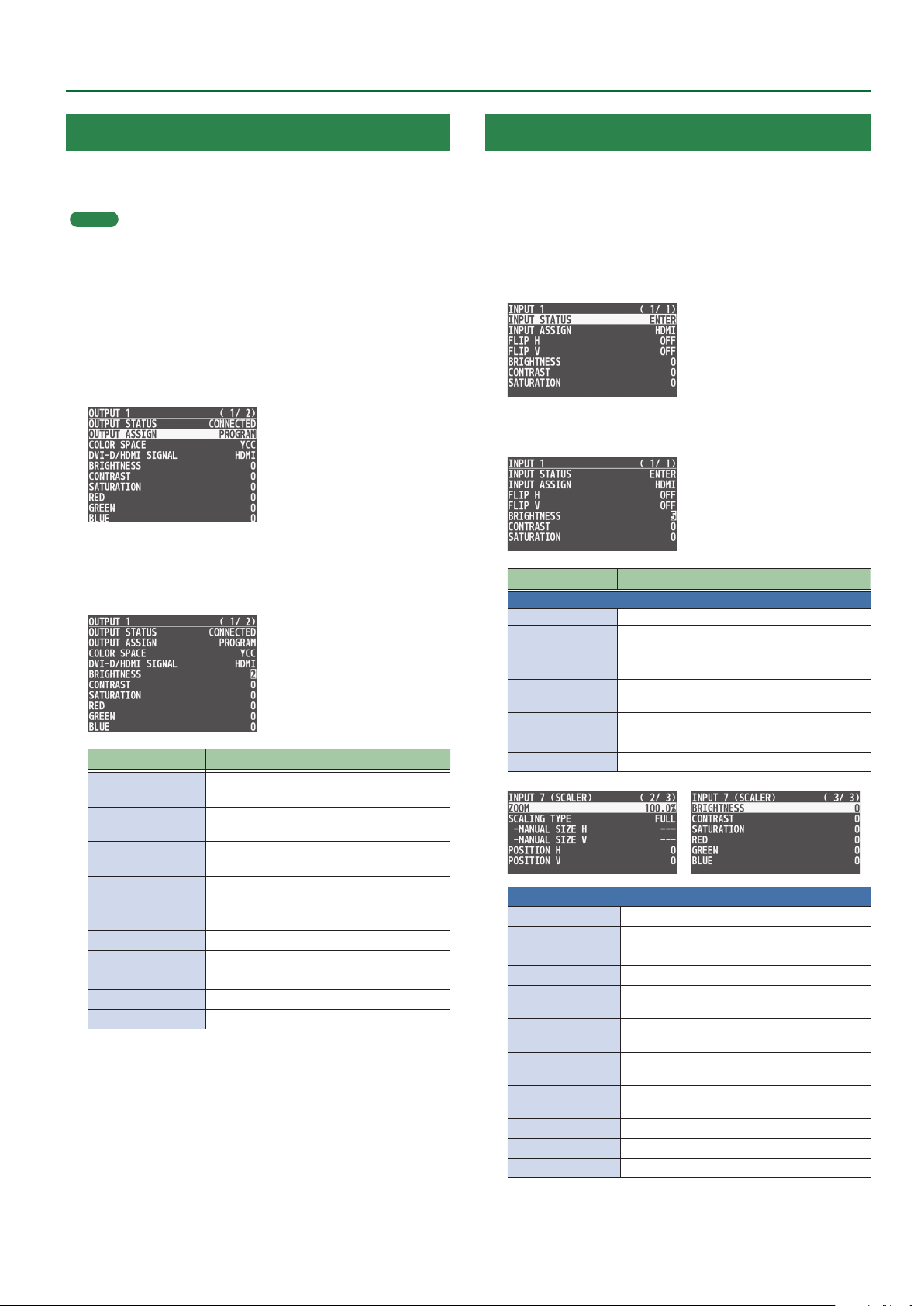
Menu item Explanation
OUTPUT STATUS
OUTPUT ASSIGN
COLOR SPACE
DVI-D/HDMI
SIGNAL
BRIGHTNESS Adjusts the brightness.
CONTRAST Adjusts the contrast.
SATURATION Adjusts the saturation.
RED Adjusts the red level.
GREEN Adjusts the green level.
BLUE Adjusts the blue level.
3. Press the [MENU] button to quit the menu.
Displays information about the output
connector.
Species the output bus that is assigned to
the OUTPUT connector.
Species the color space (system for
representing colors in video).
Species the output mode for HDMI output.
Adjusting the Input Video
Here’s how to adjust the character of the video that’s input to INPUT
1–8.
For INPUT 7 and 8 connectors, you can also adjust the scaling.
1. Press the [MENU] button0”VIDEO INPUT”0
select one of “INPUT 1” to “INPUT 8 (SCALER),” and
press the [VALUE] knob.
A menu for the selected input video appears.
2. Select a menu item, then turn the [VALUE] knob to
adjust the input video, and press the [VALUE] knob.
Menu item Explanation
INPUT 1–8
INPUT STATUS Displays information about the input video.
INPUT ASSIGN Selects the input source.
FLIP H
FLIP V
BRIGHTNESS Adjusts the brightness.
CONTRAST Adjusts the contrast.
SATURATION Adjusts the saturation.
INPUT 7, 8
FLICKER FILTER If this is “ON,” ickering is reduced.
EDID Species the input format (EDID).
ZOOM Adjusts the zoom ratio.
SCALING TYPE Species the scaling type.
MANUAL SIZE H
MANUAL SIZE V
POSITION H
POSITION V
RED Adjusts the red level.
GREEN Adjusts the green level.
BLUE Adjusts the blue level.
If this is “ON,” the video is input with left and
right ipped.
If this is “ON,” the video is input with top and
bottom ipped.
Adjusts the horizontal size when scaling
type is set to “MANUAL.”
Adjusts the vertical size when scaling type
is set to “MANUAL.”
Adjusts the display position in the
horizontal direction.
Adjusts the display position in the vertical
direction.
3. Press the [MENU] button to quit the menu.
9
Page 10
Video Input/Output Settings
Changing Output Bus Assignments
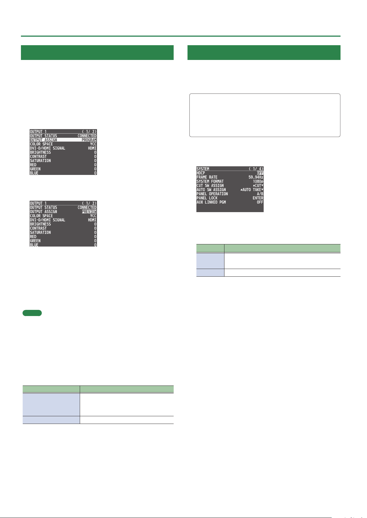
The V-8HD has four internal output buses (PROGRAM, PREVIEW, AUX,
and MULTI-VIEW).
You can select which buses to output via the OUTPUT 1–3
connectors.
1. Press the [MENU] button0”VIDEO OUTPUT”0
select one of “OUTPUT 1” to “OUTPUT 3,” and press
the [VALUE] knob.
A menu for the selected output video appears.
2. Turn the [VALUE] knob to select “OUTPUT ASSIGN,”
and press the [VALUE] knob.
Inputting Copy-Protected (HDCP) Video
If you want to input HDCP-protected video from a BD player or other
device, you can enable HDCP input.
* If you want to output HDCP-protected video, connect an HDCP-
capable display.
What’s HDCP?
HDCP is copyright-protection technology that prevents unlawful
copying of content by encoding the path when sending digital
signals from a video playback device to a display monitor or other
display equipment.
1. Press the [MENU] button0”SYSTEM”0select
“HDCP,” and press the [VALUE] knob.
2. Turn the [VALUE] knob to select “ON,” and press the
[VALUE] knob.
3. Turn the [VALUE] knob to select the output bus,
and press the [VALUE] knob.
* If a connector other than the OUTPUT 3 connector is set to “MULTI-
VIEW,” the audio meter, label, and menu etc. are not shown.
4. Press the [MENU] button to quit the menu.
MEMO
5 For details about video transitions on the A/PGM bus and B/PST
bus, refer to “Switching the Video” (p. 11).
5 For details about video transitions on the AUX bus, refer to
“Switching AUX Output” (p. 16).
About audio outputs assigned to output buses
Changing an output bus assignment makes the output audio also
change in tandem, according to the assigned bus.
Output bus assignment Output audio
PROGRAM
PREVIEW
MULTI-VIEW
AUX Outputs the audio of the AUX bus.
Outputs the audio of the MAIN bus.
Value Explanation
ON
OFF HDCP-protected video cannot be input.
HDCP-protected video can be input.
HDCP is applied to the output video.
4. Press the [MENU] button to quit the menu.
10
Page 11
Video Operations
Switching the Video
Here’s how to switch between input video while applying an eect, and nal output.
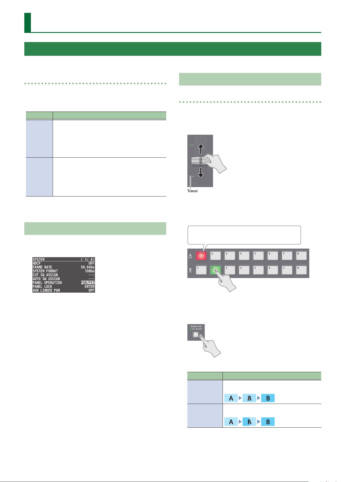
About the operation mode for video transitions
There are two operation modes for switching the video on the
PGM/A bus and PST/B bus: the “PGM/PST mode” and the “A/B mode.”
* With the factory settings, the operation mode is set to A/B mode.
Mode Explanation
When the video fader is operated, the video at the
bus position toward which the video fader is ipped
A/B
PGM/PST
always becomes the nal output.
When the [CUT] or [AUTO] button is operated, the
video on the A bus and the video on the B bus
become the nal output in alternation.
The video on the PGM bus is always the nal output.
The video on the PST bus is preset video (the video to
be output next).
Operating the video fader or the [CUT] or [AUTO]
button makes the nal video output and the preset
video change places.
Setting the Operation Mode
1. Press the [MENU] button0”SYSTEM”0select
“PANEL OPERATION,” and press the [VALUE] knob.
Using Mix/Wipe to Switch Video
When A/B mode
The video at the end to which the video fader is ipped is always the
nal output.
1. Flip the video fader all the way upward or downward.
Transition indicators
2. Press a Cross-point [1]–[8] button at the end to
which the video fader is not ipped to select the
preset video (the video to output next).
Lit red: Final output video
Lit green: Preset video (the video to be output next)
2. Turn the [VALUE] knob to select “A/B” or “PGM/PST,”
and press the [VALUE] knob.
3. Press the [MENU] button to quit the menu.
The preset video appears in the PVW section of the monitor.
3. Press the [TRANSITION] button to select the
transition eect.
The MIX or WIPE indicator is lit.
Mode Explanation
The two pictures are blended together as the
MIX
WIPE
video is switched.
The original video is broken into by the next
video.
4. Move the video fader in the direction opposite to
the direction in step 1.
The video changes.
11
Page 12
Video Operations
When PGM/PST mode is selected
1. Flip the video fader all the way upward or downward.
Transition indicators
2. Press the [TRANSITION] button to select the
transition eect.
3. Press a Cross-point B [1]–[8] button to select the
preset video (the video to be output next).
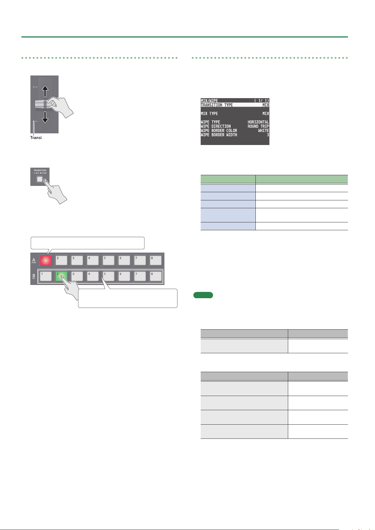
Changing the mix/wipe pattern
You can use the MIX/WIPE menu to specify the pattern by which the
mix/wipe occurs and the direction of the wipe.
1. Press the [MENU] button0select “MIX/WIPE,” and
press the [VALUE] knob.
2. Turn the [VALUE] knob to select a menu item, and
press the [VALUE] knob.
Menu item Explanation
MIX TYPE Species the transition pattern for mix.
WIPE TYPE Species the transition pattern for wipe.
WIPE DIRECTION Species the direction of wipe.
WIPE BORDER COLOR
WIPE BORDER WIDTH Exchanges the colors.
Species the color of the border added
to the edge of the wipe area.
Lit red: Final output video
Lit green:
Preset video (the video to be output next)
4. Move the video fader in the direction opposite to
the direction in step 1.
The video changes.
When the video has switched completely, the illuminated state of
the A [1]–[8] buttons and B [1]–[8] buttons is exchanged.
3. Turn the [VALUE] knob to change the value, and
press the [VALUE] knob.
For details about these values, refer to p. 47.
4. Press the [MENU] button to quit the menu.
MEMO
You can change the settings of the MIX/WIPE menu by holding down
the [TRANSITION] button and turning the SPLIT/VFX [A] or [B] knob.
5 When mix is selected
Operation Explanation
[TRANSITION] button +
turn the SPLIT/VFX [A] knob
5 When wipe is selected
Operation Explanation
[TRANSITION] button +
turn the SPLIT/VFX [A] knob
[TRANSITION] button +
turn the SPLIT/VFX [B] knob
[TRANSITION] button +
turn while pressing the SPLIT/VFX [A] knob
[TRANSITION] button +
turn while pressing the SPLIT/VFX [B] knob
MIX TYPE
WIPE TYPE
WIPE DIRECTION
WIPE BORDER COLOR
WIPE BORDER WIDTH
12
Page 13
Using the [AUTO] or [CUT] Button to Switch Video
You can use the [AUTO] or [CUT] button to switch video, without using the video fader.
* You can perform operations using the [AUTO] and [CUT] buttons both in the PGM/PST mode and in the A/B mode.
Video Operations
1. Press the [AUTO] or [CUT] button at the desired
timing for switching the video.
Button Explanation
[CUT] The picture switches instantly.
A transition eect is applied and the video is
[AUTO]
MEMO
When you use the [AUTO] or [CUT] button to switch video, the actual
output might come to dier from the position of the video fader.
Operating the video fader while in this state yields no change in
output until the position of the video fader matches the actual
output.
switched automatically.
The [AUTO] button ashes while the video transition
is in progress.
Changing the functions of the [CUT] and [AUTO] buttons
* In PGM/PST mode, the functions of the [CUT] and [AUTO] buttons
are xed.
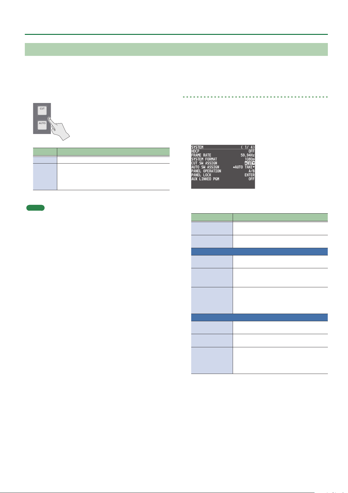
1. Press the [MENU] button0”SYSTEM”0select
“CUT SW ASSIGN” or “AUTO SW ASSIGN,” and press
the [VALUE] knob.
2. Turn the [VALUE] knob to select a function of the
button, and press the [VALUE] knob.
Function Explanation
H AUTO TAKE I
H CUT I
CUT SW ASSIGN
H AUTO TAKE
H CUT
H TRANSFORM
AUTO SW ASSIGN
AUTO TAKE I
CUT I
TRANSFORM I
Switches the video between A/PGM bus and
B/PST bus.
Switches the video between A/PGM bus and
B/PST bus as a cut.
When the video of the B/PST bus is selected,
switches to the video of the A/PGM bus.
When the video of the B/PST bus is selected,
switches to the video of the A/PGM bus as
a cut.
Switches to the video of the A/PGM bus as a
cut only while you hold down the button.
When you release your nger from the
button, the program output video returns.
When the video of the A/PGM bus is selected,
switches to the video of the B/PST bus.
When the video of the A/PGM bus is selected,
switches to the video of the B/PST bus as a cut.
Switches to the video of the B/PST bus as a
cut only while you hold down the button.
When you release your nger from the
button, the program output video returns.
3. Press the [MENU] button to quit the menu.
13
Page 14
Video Operations
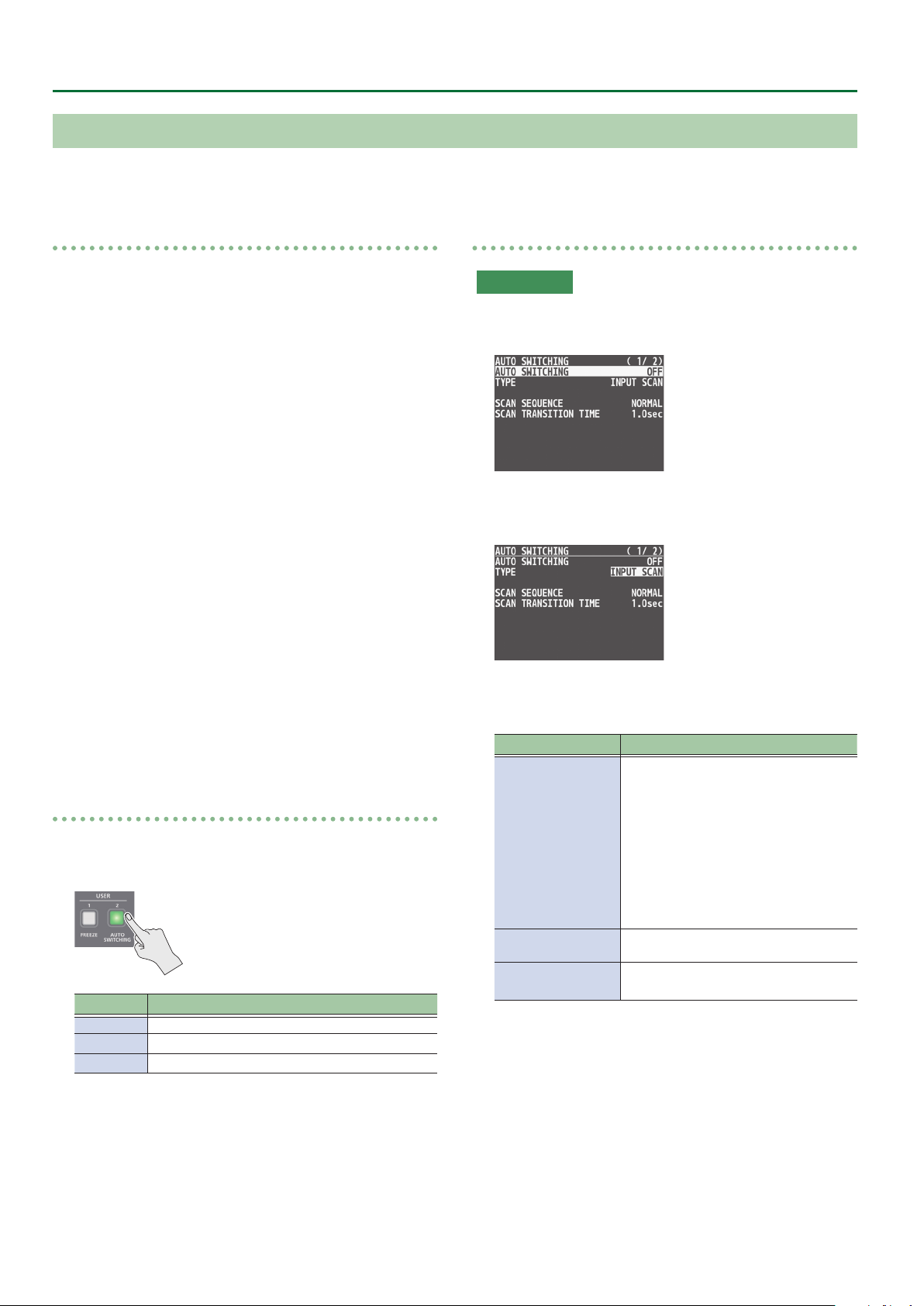
Switching the Video Automatically (Auto Switching)
The video of INPUT 1–8 or of preset memories can be switched automatically (the auto switching function). You can make operation easier by
letting the video switch automatically.
Operation modes for auto switching
Auto switching provides three operation modes that you
can select as appropriate for your situation: “input scan,”
“preset memory scan,” and “BPM sync.”
Switching at a specied interval (Input scan)
This automatically switches the INPUT 1–8 video when a specied
length of time elapses.
You can change the duration that each video is shown, and also
switch randomly between videos.
This is convenient when you want to switch between video signals
of multiple cameras, for example when live-streaming a singerinstrumentalist.
* Channels that have no video input are skipped.
Switching preset memories (Preset memory scan)
This automatically switches between preset memories 1–8.
The video and audio are switched according to the settings that are
saved in each preset memory.
* Preset memories in which no settings have been saved are
skipped.
Switching in synchronization with the BPM (BPM sync)
This automatically switches the video at specied BPM intervals.
This lets you create video transitions that are synchronized with
the music, for example when live-streaming a DJ performance or a
musical performance.
Turning the auto switching function on/o
1. Press the [AUTO SWITCHING] button to turn the
auto switching function on (lit).
Specifying the operation mode
Input scan
1. Press the [MENU] button0”AUTO SWITCHING”0
select “TYPE,” and press the [VALUE] knob.
2. Turn the [VALUE] knob to select “INPUT SCAN,” and
press the [VALUE] knob.
3. Turn the [VALUE] knob to select a menu item, and
press the [VALUE] knob.
Menu item Explanation
Species the order in which video signals
are shown.
NORMAL:
Switch in the order of INPUT 108.
SCAN SEQUENCE
REVERSE:
Switch in the order of INPUT 801.
Indicator Explanation
Green Input scan
Blue Preset memory scan
Red BPM sync
2. To turn the auto switching function o, press the
[AUTO SWITCHING] button once again.
14
RANDOM:
Switch randomly.
SCAN TRANSITION
TIME
INPUT 1 TIME–
INPUT 8 TIME
Species the video transition time.
Species the time that the INPUT 1–8
video is shown.
4. Turn the [VALUE] knob to change the value, and
press the [VALUE] knob.
5. Press the [MENU] button to quit the menu.
Page 15
Video Operations
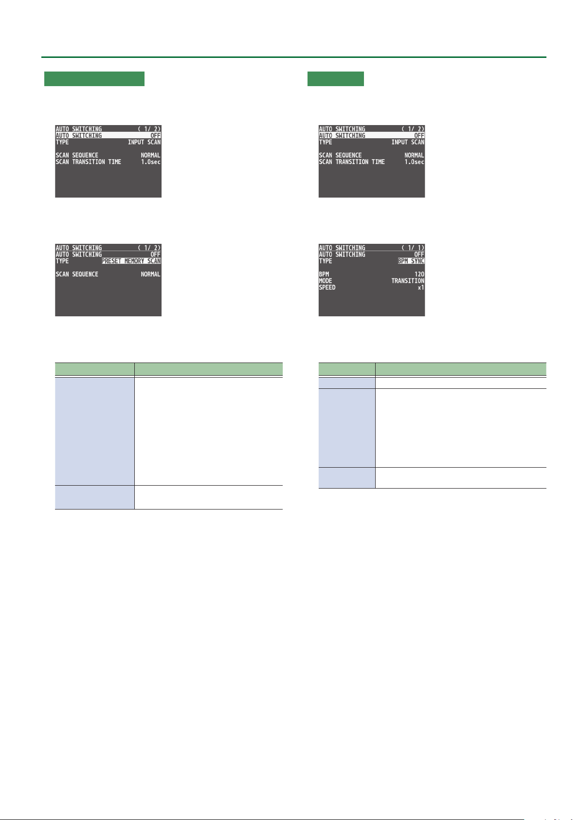
Preset memory scan
1. Press the [MENU] button0”AUTO SWITCHING”0
select “TYPE,” and press the [VALUE] knob.
2. Turn the [VALUE] knob to select “PRESET MEMORY
SCAN,” and press the [VALUE] knob.
3. Turn the [VALUE] knob to select a menu item, and
press the [VALUE] knob.
Menu item Explanation
Species the order in which preset
memories are shown.
NORMAL:
Switch in the order of MEMORY 108.
SCAN SEQUENCE
INPUT 1 TIME–
INPUT 8 TIME
REVERSE:
Switch in the order of MEMORY 801.
RANDOM:
Switch randomly.
Species the time that the MEMORY 1–8
video is shown.
4. Turn the [VALUE] knob to change the value, and
press the [VALUE] knob.
BPM sync
1. Press the [MENU] button0”AUTO SWITCHING”0
select “TYPE,” and press the [VALUE] knob.
2. Turn the [VALUE] knob to select “BPM SYNC,” and
press the [VALUE] knob.
3. Turn the [VALUE] knob to select a menu item, and
press the [VALUE] knob.
Menu item Explanation
BPM
MODE
SPEED
Species the BPM.
Species how the picture is switched.
TRANSITION:
The picture switches using the currently
selected transition eect (mix or wipe).
CUT:
The picture switches instantly.
Species the picture switching speed as a
multiple of the specied BPM.
4. Turn the [VALUE] knob to change the value, and
press the [VALUE] knob.
5. Press the [MENU] button to quit the menu.
5. Press the [MENU] button to quit the menu.
15
Page 16
Video Operations
Switching AUX Output
You can use button operations to directly select the video to send to the AUX bus.
1. Use the [MODE] button to select “AUX.”
The AUX/PinP SOURCE/MEMORY [1]–[8] buttons function as AUXbus selection buttons.
2. Press an AUX [1]–[8] button to select the AUX-bus
video.
The AUX output is switched.
MEMO
5 The display shows a green square (AUX indicator) for the input
channel that is being sent to the AUX bus.
5 For details on adjusting the volume of the AUX bus audio, refer to
“Adjusting the output volume of the AUX bus” (p. 30).
The colors of lighted AUX [1]–[8] buttons
When the [MODE] button is lighted in green, the AUX [1]–[8] buttons
also function as indicators showing the status of video input.
Button Explanation
Lit white Valid video is being input.
Blink white
Unlit No video is input.
Video whose format diers from the system format
setting is input.
Sending the same video as the PGM output to the
AUX output
By using the AUX link function, you can send the same video as the
PGM bus (the nal output video) to the AUX bus.
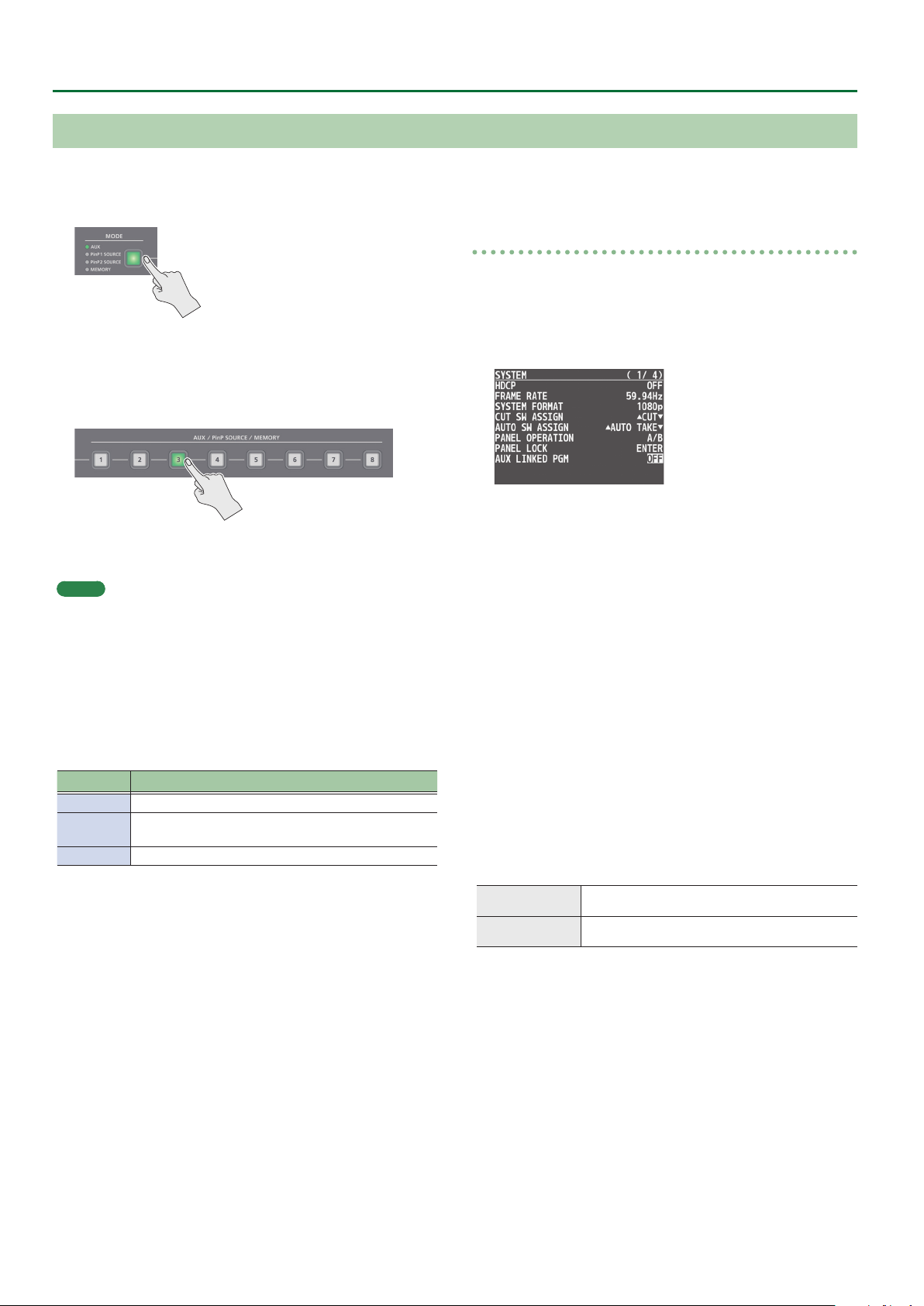
1. Press the [MENU] button0”SYSTEM”0select
“AUX LINKED PGM,” and press the [VALUE] knob.
2. Turn the [VALUE] knob to select “AUTO LINK” or
“MANUAL LINK,” and press the [VALUE] knob.
If you're not using the AUX link function, turn this “OFF.”
3. Press the [MENU] button to quit the menu.
Selecting the AUX output
In the case of “OFF”
Press an AUX [1]–[8] button to select the video of the AUX bus.
In the case of “AUTO LINK” or “MANUAL LINK”
AUX link is enabled, and the same video as the PGM bus is sent to the
AUX bus.
Temporarily disabling AUX link
When you press an AUX [1]–[8] button, the selection of the AUX [1]–
[8] button is enabled (lit green).
Re-enabling AUX link
AUTO LINK
MANUAL LINK
When you operate the [AUTO] button etc. to switch the
video of the PGM bus, AUX link is automatically enabled.
When you press the AUX/MEMORY button that is currently
selected (lit green), AUX link is enabled.
16
Page 17
A B
A B
A B
Compositing Video with Split (SPLIT)
This composites two video streams in a split screen. The nal output
video is displayed above or on the left, and the preset video (the
video to be output next) is displayed below or on the right.
Video Operations
Specifying a Split Composition Pattern
This makes the settings for the split composition pattern to match
the video you want to composite.
1. Press the [MENU] button0”SPLIT/VFX”0select
“SPLIT/VFX A” or “SPLIT/VFX B,” and press the
[VALUE] knob.
2. Turn the [VALUE] knob to select “SPLIT/VFX TYPE,”
and press the [VALUE] knob.
Compositing Using Split
1. Press a Cross-point A [1]–[8] button to select the
video you want to display above or on the left.
2. Press a Cross-point B [1]–[8] button to select the
video you want to display below or on the right.
3. Press the SPLIT/VFX [A] or [B] button to turn on
SPLIT (lighted).
3. Turn the [VALUE] knob to select the SPLIT type, and
press the [VALUE] knob.
You can select “SPLIT V” or “SPLIT H.”
Value Explanation
SPLIT V
SPLIT H
This vertically crops the center
section of the video.
This horizontally crops the center
section of the video.
A B
A
A
B
B
4. Press the [MENU] button to quit the menu.
MEMO
For each of the split screens, you can adjust the displayed position
of the video and change the color or width of the border. For details,
refer to p. 48 of “Menu list.”
The video you selected in steps 1 and 2 is composited.
4. Turn the SPLIT/VFX [A] or [B] knob to adjust the
display position of the video.
MEMO
By turning the knob while pressing it, you can adjust the position
of the dividing line between the two videos.
5. To turn o SPLIT, press the SPLIT/VFX [A] or [B]
button once again.
17
Page 18

Video Operations
Using a Visual Eect (VFX)
Here’s how you can apply an eect to the entire video, such as varying the video’s color or shape.
You can apply a visual eect (VFX) to the A/PGM bus and B/PST bus respectively.
Selecting a Visual Eect
1. Press the [MENU] button0”SPLIT/VFX”0select
“SPLIT/VFX A” or “SPLIT/VFX B,” and press the
[VALUE] knob.
2. Turn the [VALUE] knob to select “SPLIT/VFX TYPE,”
and press the [VALUE] knob.
3. Turn the [VALUE] knob to select the visual eect,
and press the [VALUE] knob.
* With the factory settings, “PART MOSAIC” is specied.
Applying Visual Eects
1. Press a Cross-point A or B [1]–[8] button to output
the video to which you want to apply the eect.
2. Press the SPLIT/VFX [A] or [B] button to turn on the
visual eect (making the button light up).
The visual eect is applied to the output video.
3. Turn the SPLIT/VFX [A] or [B] knob to adjust the
degree of eect applied.
Type Explanation
PART MOSAIC
BACKGROUND
MOSAIC
FULL MOSAIC
WAVE
RGB REPLACE
COLORPASS
NEGATIVE
COLORIZE
POSTERIZE
SILHOUETTE
EMBOSS
FIND EDGES
MONOCOLOR
HUE OFFSET
SATURATION
OFFSET
VALUE OFFSET
Applies a mosaic to the selected region.
Applies a mosaic to the portion outside the
selected region.
Applies a mosaic to the entire screen.
Makes the video wavy.
Exchanges the colors.
Turns the video black and white while
preserving a specic color.
Inverts the brightness and saturation.
Adds color to the video.
Changes the gradations in brightness.
Separates the video into light and dark areas,
and makes the dark areas black and adds a
dierent color to the light areas.
Adds a bas-relief eect to the video.
Extracts contours.
Turns the video monochrome.
Changes the visual character by controlling
the hue.
Changes the visual character by controlling
the saturation.
Changes the visual character by controlling
the brightness.
MEMO
5 For “PART MOSAIC” and “BACKGROUND MOSAIC,” you can adjust
the following settings.
Knob operation Explanation
Adjusts the horizontal position of the selected area.
Turning
Turn while pressing
5 Settings for the eect that is controlled by the SPLIT/VFX [A] or [B]
knobs can be checked in the VFX menu.
5 By holding down the SPLIT/VFX [A] ([B]) button and turning the
SPLIT/VFX [A] ([B]) knob, you can change the type of visual eect.
While pressing an A or B [1]–[8] button:
Adjusts the size of the selected area.
Adjusts the vertical position of the selected area.
While pressing an A or B [1]–[8] button:
Species the neness (block size) of the mosaic.
4. To turn o a visual eect, press the SPLIT/VFX [A] or
[B] button once again.
4. Press the [MENU] button to quit the menu.
18
Page 19
Compositing Video with Picture-in-Picture (PinP)
Video Operations
Here’s how to composite an inset screen (a small separate screen)
onto the background video.
You can use PinP 1 and PinP 2 simultaneously to composite two inset
screens.
Here we explain the procedure for compositing video using “PinP
1.” You can also composite video using the same procedure using
“PinP 2.”
1. Press a Cross-point A or B [1]–[8] button to select
the video you want to make the background video.
2. Press the [MODE] button to select “PinP1 SOURCE.”
PinP 1
PinP 2
Inset screen 1
(PinP 1)
Inset screen 2
(PinP 2)
Background video
5. Use the PinP 1 [POSITION H] and [POSITION V] knobs
to adjust the display position of the inset screen.
Knob Explanation
Adjusts the inset screen’s display position
[POSITION H]
[POSITION V]
horizontally.
Turn while pressing:
Adjusts the size of the inset screen.
Adjusts the inset screen’s display position
vertically.
Turn while pressing:
Adjusts the zoom of the video shown in the
inset screen.
3. Press a PinP SOURCE [1]–[8] button to select the
video you want to make the inset screen.
4. Press the PinP 1 [PVW] button to preview-output
the video of the inset screen.
The PinP 1 [PVW] button lights up in green and the inset screen
appears in the PVW section of the monitor, allowing you to check
the inset screen’s location and size.
At this stage, the nal output has not yet been changed.
6. Press the PinP 1 [ON] button to turn on PinP
compositing (lit).
The PinP 1 [ON] button lights up in red, and the inset screen is
composited onto the background video and the result is sent to
nal output.
7. To turn o PinP compositing, press the PinP 1 [ON]
button once again.
MEMO
5 By long-pressing the PinP 1 (2) [PVW] button, you can access
the mode for selecting the inset screen without having to press
the [MODE] button and then select “PinP1 SOURCE” or “PinP2
SOURCE.”
While pressing the PinP 1 (2) [PVW] button, press a PinP SOURCE
[1]–[8] button to select the video that you want to use as the inset
screen.
5 The fade time over which the inset screen appears or disappears
when you press the [ON] button is specied by the setting of the
TRANSITION TIME menu item “PinP 1 TIME” or “PinP 2 TIME.”
19
Page 20
Video Operations
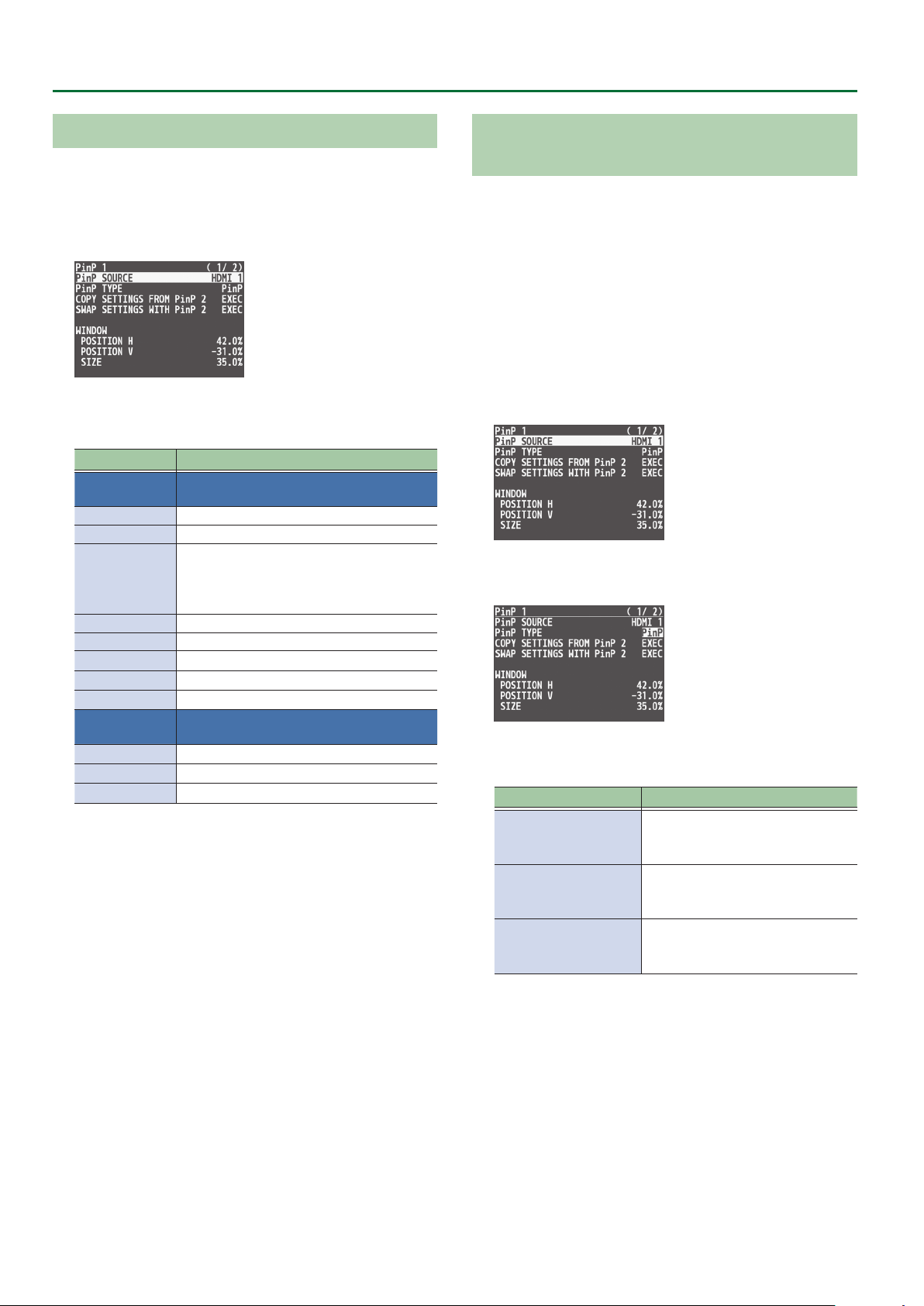
Making Detailed Settings for the Inset Screen
Detailed settings for size, shape, and border width etc. can be made
for the PinP 1 and PinP 2 inset screens respectively.
1. Press the [MENU] button0”PinP”0select “PinP 1”
or “PinP 2,” and press the [VALUE] knob.
2. Turn the [VALUE] knob to select a menu item, and
press the [VALUE] knob.
Menu item Explanation
WINDOW
POSITION H
POSITION V
SIZE
CROPPING H
CROPPING V
SHAPE
BORDER COLOR
BORDER WIDTH
VIEW
POSITION H
POSITION V
ZOOM
3. Turn the [VALUE] knob to change the value, and
press the [VALUE] knob.
4. Press the [MENU] button to quit the menu.
Use the following items to adjust the inset
screen.
Adjusts horizontal display position.
Adjusts vertical display position.
Adjusts the size (zoom).
This species the inset screen’s horizontal width
as a proportion of the background video’s
horizontal width.
Adjusts the horizontal frame size.
Adjusts the vertical frame size.
Species the shape (rectangle, circle, diamond).
Species the color of the border.
Adjusts the width of the border.
Use the following items to adjust the video
that is shown in the inset screen.
Adjusts the horizontal position.
Adjusts the vertical position.
Adjusts the zoom.
Using Key Compositing to Remove the PinP
Background Video
By changing the PinP type, you can composite the video by applying
“luminance key” (p. 22) or “chroma key” (p. 24) to the PinP.
If you apply the luminance key function, the black or white portion
of the inset screen becomes transparent, extracting the text or image
and compositing it onto the background video.
If you apply the chroma key function, and a video that was shot
against a blue or green backdrop is selected as the inset screen,
the blue or green portion of the inset screen becomes transparent,
extracting only the subject and compositing it onto the background
video.
1. Press the [MENU] button0”PinP”0select “PinP 1”
or “PinP 2,” and press the [VALUE] knob.
2. Turn the [VALUE] knob to select “PinP TYPE,” and
press the [VALUE] knob.
3. Turn the [VALUE] knob to select the PinP type, and
press the [VALUE] knob.
Type Explanation
Composite using luminance key.
LUMINANCE-WHITE KEY
LUMINANCE-BLACK KEY
CHROMA KEY
Makes white portions transparent
according to brightness.
Composite using luminance key.
Makes black portions transparent
according to brightness.
Composite using chroma key.
Makes the specied key color
transparent according to hue.
20
4. Press the [MENU] button to quit the menu.
Page 21
Video Operations
Copying the PinP Settings
You can copy the PinP 2 settings to PinP 1, or the settings of PinP 1 to
PinP 2.
1. Press the [MENU] button0”PinP”0select “PinP 1”
or “PinP 2,” and press the [VALUE] knob.
2. Turn the [VALUE] knob to select “COPY SETTINGS
FROM PinP 2 (or PinP 1),” and press the [VALUE] knob.
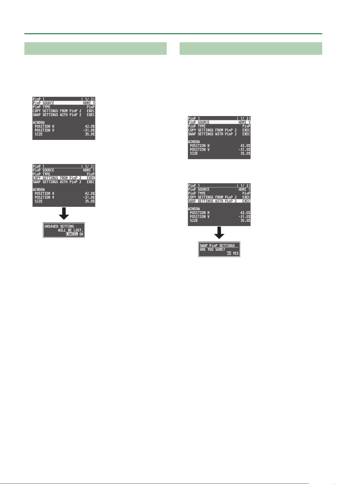
Exchanging the PinP 1 and PinP 2 Settings
You can exchange the settings of PinP 1 and PinP 2.
By using this function when (for example) the PinP 1 inset screen
is in the foreground and the PinP 2 inset screen is behind, you can
exchange the settings so that the PinP 1 screen moves behind and
the PinP 2 inset screen moves to the foreground.
1. Press the [MENU] button0”PinP”0select “PinP 1”
or “PinP 2,” and press the [VALUE] knob.
2. Turn the [VALUE] knob to select “SWAP SETTINGS
WITH PinP 2 (or PinP 1),” and press the [VALUE] knob.
A conrmation message appears.
* If you decide to cancel, press the [EXIT] button.
3. Turn the [VALUE] knob to select “OK,” and press the
[VALUE] knob.
The PinP settings are copied.
When the operation is nished, the message “COMPLETE” appears.
4. Press the [MENU] button to quit the menu.
A conrmation message appears.
* If you decide to cancel, press the [EXIT] button.
3. Turn the [VALUE] knob to select “YES,” and press the
[VALUE] knob.
The PinP 1 and PinP 2 settings are exchanged.
When the operation is nished, the message “COMPLETE” appears.
4. Press the [MENU] button to quit the menu.
21
Page 22
Video Operations
Compositing Video with Downstream Keyer (DSK)
Here’s how you can turn a portion of the video transparent and composite it with the background video. You can use luminance key with either a
black or a white background, or a chroma key with either a blue or green background.
You can additionally composite a variety of text and images with video that was composited using PinP or another method.
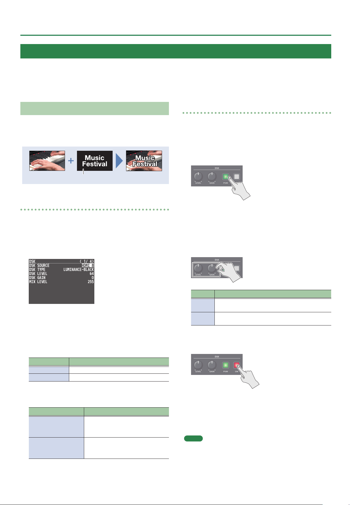
Using Luminance Key
Luminance key
This cuts out text or an image by turning the black or white portion
transparent, and composites it onto the background video.
Black or white
Specifying the source and key type for the video
Specify the source and key type for the video that you want to
superimpose.
1. Press the [MENU] button0”DSK”0select “DSK
SOURCE” or “DSK TYPE,” and press the [VALUE]
knob.
Compositing using luminance key
1. Output the background video.
At the PVW section of the monitor, check the video to be made
the background.
2. Press the DSK [PVW] button to turn on the preview
output (lit).
The DSK [PVW] button lights up in green, and a preview of
the composition results is displayed in the PVW section of the
monitor.
At this stage, the nal output has not yet been changed.
3. Turn the DSK [LEVEL] and [GAIN] knob to adjust the
degree of eect applied.
2. Turn the [VALUE] knob to change the value, and
press the [VALUE] knob.
DSK SOURCE
Select the source of the logo or image that you want to
superimpose.
Value Explanation
HDMI 1–8 INPUT 1–8 video
STILL 1–8 Captured still image 1–8
DSK TYPE
Choose “LUMINANCE-WHITE” or “LUMINANCE-BLACK.”
Value Explanation
Composite using luminance key.
LUMINANCE-WHITE
LUMINANCE-BLACK
Makes white portions transparent
according to brightness.
Composite using luminance key.
Makes black portions transparent
according to brightness.
Knob Explanation
[LEVEL]
[GAIN]
Adjusts the degree of extraction (transparency) for
the key.
Adjusts the degree of edge blur (semi-transmissive
region) for the key.
4. Press the DSK [ON] button to turn on luminance key
composition (lit).
The DSK [ON] button lights up in red, and the composition results
is sent to nal output.
5. To turn o luminance key compositing, press the
DSK [ON] button once again.
MEMO
The fade time over which the logo/image appears or disappears
when you press the DSK [ON] button is specied by the setting of the
TRANSITION TIME menu item “DSK TIME.”
3. Press the [MENU] button to quit the menu.
22
Page 23
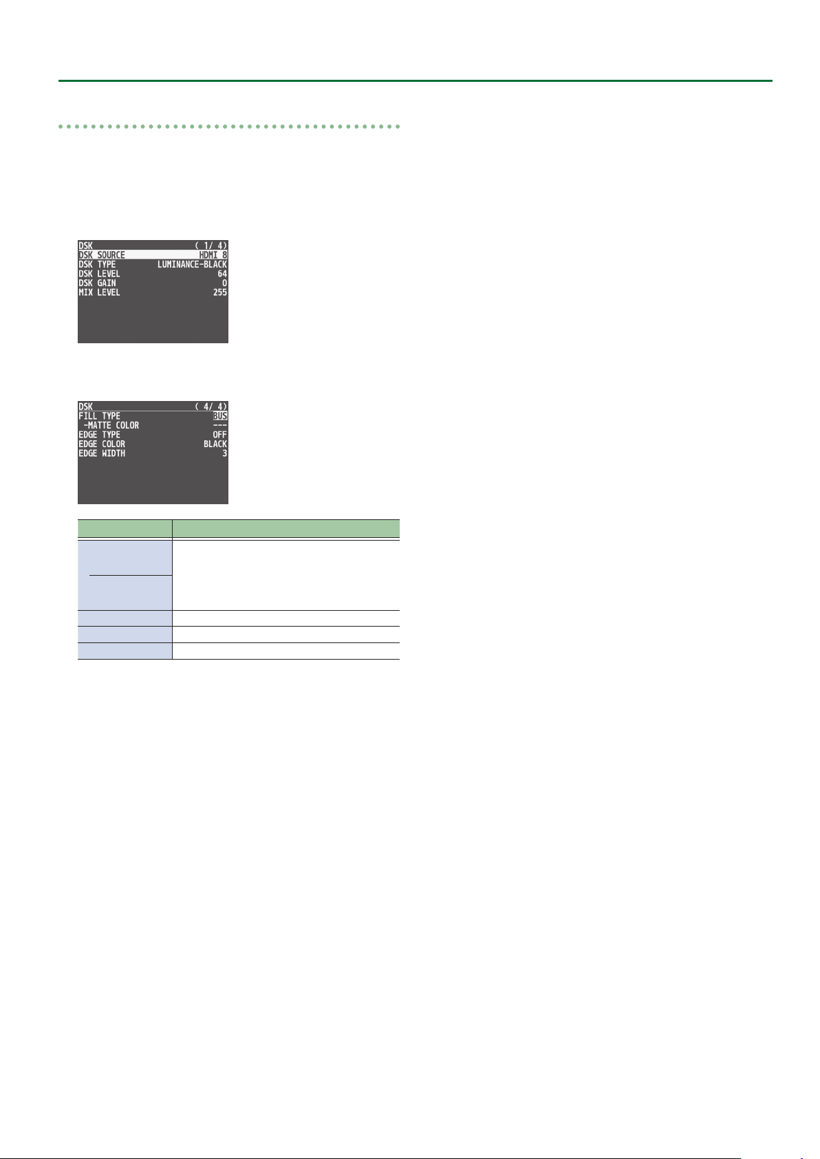
Modifying the superimposed video
When using luminance key compositing, you can ll-in the
superimposed image or add an edge to it.
* This setting is in common with chroma key.
1. Press the [MENU] button0select “DSK,” and press
the [VALUE] knob.
2. Turn the [VALUE] knob to select the menu items
shown below, and press the [VALUE] knob.
Video Operations
Menu item Explanation
FILL TYPE
MATTE COLOR
EDGE TYPE
EDGE COLOR
EDGE WIDTH
If this is set to “MATTE,” the superimposed
logo or image is lled-in with the specied
color.
The ll-in color is specied by “MATTE COLOR.”
Species the type of edge.
Species the color of the edge.
Species the width of the edge.
3. Turn the [VALUE] knob to change the value, and
press the [VALUE] knob.
4. Press the [MENU] button to quit the menu.
23
Page 24
Video Operations
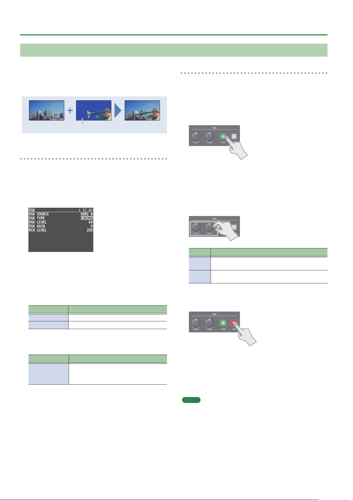
Using Chroma Key
Chroma key
This cuts out a video by turning the blue or green portion
transparent, and composites it onto the background video. Using
this, you can composite only a subject that you are photographing
against a blue screen or green screen.
Blue or green
Specifying the source and key type for the video
Specify the source and key type for the video that you want to
superimpose.
1. Press the [MENU] button0”DSK”0select “DSK
SOURCE,” “DSK TYPE,” or “COLOR,” and press the
[VALUE] knob.
Compositing using chroma key
1. Output the background video.
At the PVW section of the monitor, check the video to be made
the background.
2. Press the DSK [PVW] button to turn on the preview
output (lit).
The DSK [PVW] button lights up in green, and a preview of
the composition results is displayed in the PVW section of the
monitor.
At this stage, the nal output has not yet been changed.
3. Turn the DSK [LEVEL] and [GAIN] knob to adjust the
degree of eect applied.
2. Turn the [VALUE] knob to change the value, and
press the [VALUE] knob.
DSK SOURCE
Select the source of the logo or image that you want to
superimpose.
Value Explanation
HDMI 1–8 INPUT 1–8 video
STILL 1–8 Captured still image 1–8
DSK TYPE
Set to “CHROMA.”
Value Explanation
Composite using chroma key.
CHROMA
Makes the specied key color transparent
according to hue.
COLOR
Specify either “GREEN” or “BLUE” as the key color for chroma key
(the color to be removed).
3. Press the [MENU] button to quit the menu.
Knob Explanation
[LEVEL]
[GAIN]
Adjusts the degree of extraction (transparency) for
the key.
Adjusts the degree of edge blur (semi-transmissive
region) for the key.
4. Press the DSK [ON] button to turn on chroma key
composition (lit).
The DSK [ON] button lights up in red, and the composition results
is sent to nal output.
5. To turn o chroma key compositing, press the DSK
[ON] button once again.
MEMO
The fade time over which the logo/image appears or disappears
when you press the DSK [ON] button is specied by the setting of the
TRANSITION TIME menu item “DSK TIME.”
24
Page 25
Video Operations
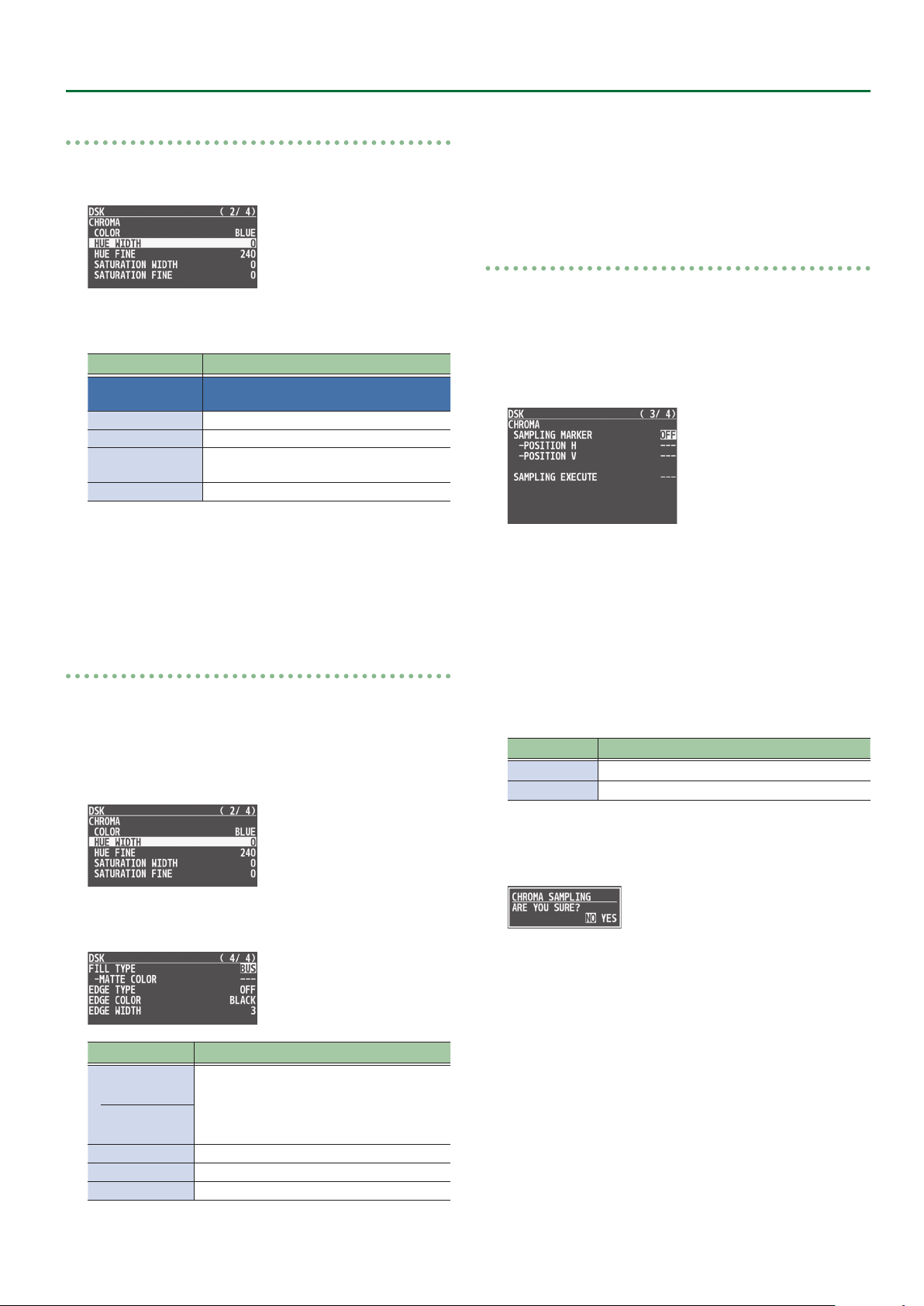
Finely adjusting the key color (removed color)
1. Press the [MENU] button0select “DSK,” and press
the [VALUE] knob.
2. Turn the [VALUE] knob to select the menu items
shown below, and press the [VALUE] knob.
Menu item Explanation
CHROMA
HUE WIDTH Adjusts the hue width.
HUE FINE Adjusts the center position of the hue.
SATURATION
WIDTH
SATURATION FINE Adjusts the center position of saturation.
3. Turn the [VALUE] knob to change the value, and
press the [VALUE] knob.
4. Press the [MENU] button to quit the menu.
Use the following items to make ne
adjustments to the key color.
Adjusts the saturation width.
3. Turn the [VALUE] knob to change the value, and
press the [VALUE] knob.
4. Press the [MENU] button to quit the menu.
To specify a desired color as the key color (sampling marker)
You can specify the key color to be made transparent simply by
sampling (detecting) a color from the video. (This is called the
sampling marker function.) You can also specify a key color other
than green or blue.
1. Press the [MENU] button0”DSK”0select
“SAMPLING MARKER,” and press the [VALUE] knob.
2. Turn the [VALUE] knob to select “ON,” and press the
[VALUE] knob.
The sampling marker (cross-shaped cursor) is shown on the monitor
of the unit and in the OUTPUT 3 connector’s output video.
Modifying the superimposed video
When using chroma key compositing, you can ll-in the superimposed
image or add an edge to it.
* This setting is in common with luminance key.
1. Press the [MENU] button0select “DSK,” and press
the [VALUE] knob.
2. Turn the [VALUE] knob to select the menu items
shown below, and press the [VALUE] knob.
Menu item Explanation
FILL TYPE
MATTE COLOR
EDGE TYPE
EDGE COLOR
EDGE WIDTH
If this is set to “MATTE,” the superimposed
logo or image is lled-in with the specied
color.
The ll-in color is specied by “MATTE COLOR.”
Species the type of edge.
Species the color of the edge.
Species the width of the edge.
3. Turn the [VALUE] knob to select “POSITION H” or
“POSITION V,” and press the [VALUE] knob.
4. Turn the [VALUE] knob to adjust the position of the
sampling marker.
Menu item Explanation
POSITION H
POSITION V
Adjusts the horizontal position.
Adjusts the vertical position.
5. Turn the [VALUE] knob to select “SAMPLING EXECUTE,”
and press the [VALUE] knob
A conrmation message appears.
* If you decide to cancel, press the [EXIT] button.
.
6. Turn the [VALUE] knob to select “YES,” and press the
[VALUE] knob.
The key color is sampled.
The “HUE WIDTH,” “HUE FINE,” “SATURATION WIDTH,” and
“SATURATION FINE” settings are adjusted automatically.
7. Press the [MENU] button to quit the menu.
25
Page 26
Video Operations
Using Imported Still Images
You can take a still image captured from input/output video or imported from a USB ash drive, assign it to channel 1 or 8, and output it in the
same way as video. You can also use it as a source for DSK compositing (p. 22).
You can save up to eight still images in the unit.
* When still images are saved in the unit, startup takes longer time according to image size and the number of still images saved.
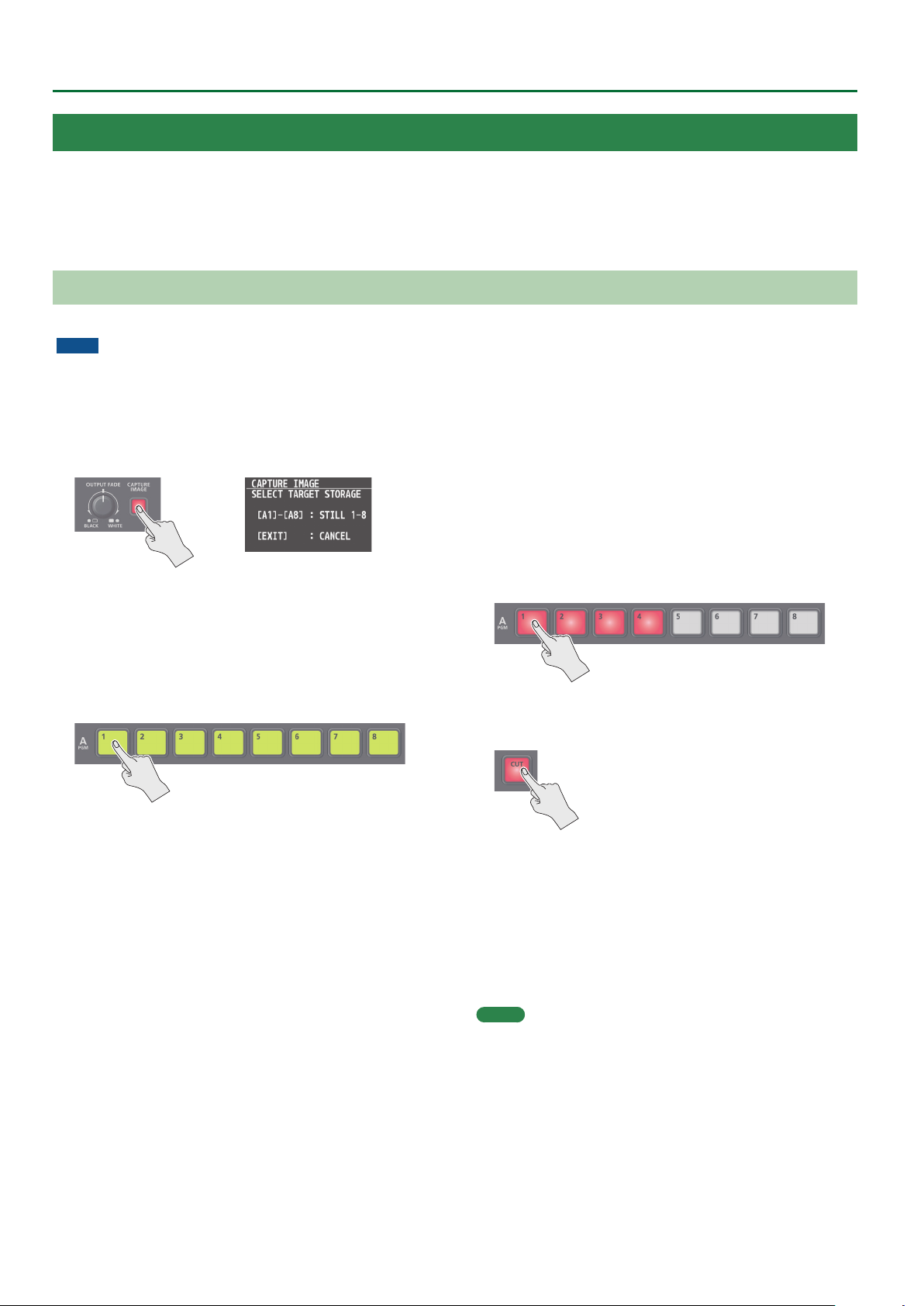
Capturing a Still Image from Input/Output Video
This captures a still image from input/output video and saves it in the unit.
NOTE
5 All audio stops during still-image capture.
5 Depending on the format of the input video, completion of still-image capture might take some time.
5 Created still images cannot be saved to a USB ash drive.
1. Press the [CAPTURE IMAGE] button to turn on (lit).
The monitor shows a list of still images (STILL 1–8).
The Cross-point A [1]–[8] buttons blink yellow.
2. Press a Cross-point A [1]–[8] button to select a save-
destination (STILL 1–8) for the captured still image.
* If you decide to cancel, press the [EXIT] button.
5 When you select the save-destination for the still image, the list of
still images changes to a list of video inputs (HDMI 1–8).
5 The Cross-point A buttons of channels that are inputting video
and the [CUT] button blink red.
3. Press a button that is blinking red to capture a still
image.
* If you decide to cancel, press the [EXIT] button.
If you press a Cross-point A [1]–[8] button
The still image is captured from the video that is being input to
the channel whose button you pressed.
If you press the [CUT] button
The still image is captured from the PGM (nal output) video.
5 When you execute capture, the list of input video changes to a list
of still images.
* Do not turn o the power while the “PLEASE WAIT” message is
shown.
26
4. When the display indicates “COMPLETE,” press the
[EXIT] button to exit the operation.
MEMO
When you have captured from copyright-protected (HDCP) video, the
created still image is treated the same way as HDCP applied video.
The still image is switched between displayed and hidden by turning
HDCP on and o (p. 10).
Note, however, that when HDCP is switched from o to on, the still
image is reloaded from where it’s saved in memory, and so the still
image might take some time to display.
Page 27
Video Operations
Importing a Still Image from a USB Flash Drive
This imports into the unit a still image saved on a USB ash drive.
Supported still-image formats and resolutions
Bitmap (.bmp), 24-bit color, uncompressed
Format
Resolution
File name
Importing a still image
NOTE
5 Large-size still-image les might take some time to import.
5 When you’re using a USB ash drive for the rst time, be sure to
format it on the V-8HD (p. 39).
5 Depending on the USB ash drive, recognition of the ash drive
might take some time.
1. Save the still image in the root directory of the USB
ash drive.
2. Connect the USB ash drive containing the saved
still image to the USB MEMORY port.
3. Press the [MENU] button0”STILL IMAGE”0select
“LOAD FROM USB MEMORY,” and press the [VALUE]
knob.
PNG (.png), 24-bit color
* α-channel is not supported.
In conformity with system format (p. 8)
No more than 28 single-byte alphanumeric characters
* Be sure to append the “.bmp” or “.png” le extension.
Assigning Still Images to Channel 1–8
Here’s how a still image saved in this unit (STILL 1–8) can be assigned
to channels 1–8.
1. Press the [MENU] button0”VIDEO INPUT”0
select “INPUT 1”–“INPUT 8 (SCALER),” and press the
[VALUE] knob.
2. Turn the [VALUE] knob to select “INPUT ASSIGN,”
and press the [VALUE] knob.
3. Turn the [VALUE] knob to select “STILL 1”–“STILL 8,”
and press the [VALUE] knob.
4. Press the [MENU] button to quit the menu.
MEMO
5 By holding down the [EXIT] button and pressing a Cross-point
A or B [1]–[8] button, you can switch between still images STILL
1–8 and select the still image that is assigned to the channel
whose button you pressed.
4. Turn the [VALUE] knob to select the still image
save-destination (STILL 1–8), and then press the
[VALUE] knob.
A “ * ” symbol is displayed for memory where a still image is
already saved.
5. Press the [VALUE] knob.
The names of the les on the USB ash drive are displayed on this
screen.
6. Select the still image le you want to import, and
press the [VALUE] knob.
A conrmation message appears.
* If you decide to cancel, press the [EXIT] button.
7. Turn the [VALUE] knob to select “YES,” and press the
[VALUE] knob.
The still image is imported into the unit.
8. Press the [MENU] button to quit the menu.
5 You can use the USER [1] or [2] button to output the specied
still image.
This lets you directly output a still image to PGM and PVW
without assigning it to a channel.
For details on this setting, refer to “Assigning the Functions of
the USER [1] [2] Buttons” (p. 42).
5 You can use the [OUTPUT FADE] knob to output a specied still
image.
This lets you directly output a still image to PGM and PVW
without assigning it to a channel.
For details on this setting, refer to “Specifying the function of
the [OUTPUT FADE] knob” (p. 29).
5 You can use a footswitch or expression pedal to output a
specied still image. This lets you directly output a still image to
PGM and PVW without assigning it to a channel.
For details on this setting, refer to the following.
– “Using a Footswitch” (p. 40)
– “Using an Expression Pedal” (p. 41)
27
Page 28

Video Operations
Deleting a Still Image
Here’s how to delete the still image that’s saved in the unit.
1. Press the [MENU] button0”STILL IMAGE”0select
“DELETE STILL IMAGE,” and press the [VALUE] knob.
2. Turn the [VALUE] knob to select the still image you
want to delete, and press the [VALUE] knob.
A conrmation message appears.
* If you decide to cancel, press the [EXIT] button.
3. Turn the [VALUE] knob to select “YES,” and press the
[VALUE] knob.
The still image is deleted. When the operation is nished, the
message “COMPLETE” appears.
* Do not turn o the power while the “PLEASE WAIT” message is
shown.
4. Press the [MENU] button to quit the menu.
Freezing Input Video (Freeze)
This temporarily pauses the incoming video.
You can apply transition eects and visual eects during a video
freeze.
Setting the freeze mode
There are two freeze modes: “ALL” and “SELECT.”
* With the factory settings, “ALL” is selected.
Mode Explanation
ALL Freezes all video that is being input.
SELECT Freezes only the specied input video.
1. Press the [MENU] button0”FREEZE”0select
“TYPE,” and press the [VALUE] knob.
2. Turn the [VALUE] knob to select “ALL” or “SELECT,”
and press the [VALUE] knob.
If “SELECT” is selected
3. Turn the [VALUE] knob to select “INPUT 1”–“INPUT 8,”
and press the [VALUE] knob.
28
4. Turn the [VALUE] knob to select “ENABLE” or
“DISABLE,” and press the [VALUE] knob.
Value Explanation
ENABLE The input video freezes.
DISABLE The input video does not freeze.
5. Press the [MENU] button to quit the menu.
Page 29

Video Operations
Applying a Fade to the Output Video (Output Fade)
You can apply a fade to the output video.
This lets you make the main output video fade to a black (or white) picture at times when you want to suppress video output, such as during
intervals in a presentation, event or band performance.
Applying a Fade-out
1. Turn the [OUTPUT FADE] knob all the way clockwise
or counterclockwise.
Turning the [OUTPUT FADE] knob clockwise performs a fade-out
to white, and turning the knob counterclockwise performs a fadeout to black (factory setting).
Applying a fade makes the indicators to the left or right of the
knob ash.
Applying a Fade-in
1. Return the [OUTPUT FADE] knob to its center
position.
The indicator stops ashing and lights up steadily, and output
starts.
Specifying the function of the [OUTPUT FADE] knob
You can assign the following functions to the [OUTPUT FADE] knob.
5 Fade the output video.
5 Adjusts the volume of the output audio.
5 Output a specied still image.
1. Press the [MENU] button0“SYSTEM”0select
OUTPUT FADE ASSIGN “TURN LEFT” or “TURN
RIGHT,” and then press the [VALUE] knob.
2. Turn the [VALUE] knob to select the function of the
[OUTPUT FADE] knob, and then press the [VALUE]
knob.
Value Explanation
BLACK Fade out to black.
WHITE Fade out to white.
AUDIO Adjust the volume of the output audio.
Simultaneously apply the fade-to-black
BLACK&AUDIO
WHITE&AUDIO
STILL 1–8 OUTPUT Output the specied still image.
and the output audio volume adjustment
functions.
Simultaneously apply the fade-to-white
and the output audio volume adjustment
functions.
3. Press the [MENU] button to quit the menu.
29
Page 30

Audio Operations
Adjusting the Volume Level
Here’s how to adjust the volume of the audio input and audio output.
1. Press the
[
MENU] button0”AUDIO INPUT”0select
“INPUT 1”–“INPUT 8” or “AUDIO IN,” and press the
[VALUE] knob.
2. Turn the [VALUE] knob to select “INPUT LEVEL,” and
press the [VALUE] knob.
3. Turn the [VALUE] knob to adjust the input volume,
and press the [VALUE] knob.
4. Press the [MEMU] button.
5. Press the [MENU] button0”AUDIO OUTPUT”0
”MASTER OUTPUT”0select “OUTPUT LEVEL,” and
press the [VALUE] knob.
MEMO
5 If the OUTPUT FADE ASSIGN (p. 29) setting is “BLACK&AUDIO”
or “WHITE&AUDIO,” using the [OUTPUT FADE] knob to fade-in/
out the output video will simultaneously fade-in/out the output
audio as well.
5 If the OUTPUT FADE ASSIGN (p. 29) setting is “AUDIO,” you can
use the [OUTPUT FADE] knob to adjust only the output volume.
5 You can output a test tone that is useful when making volume
adjustments.
In the SYSTEM menu item “TEST TONE” (p. 67), specify the test
tone that you want to output.
Adjusting the output volume of the AUX bus
1. Press the [MENU] button0”AUDIO OUTPUT”0
”AUX”0select “AUX LEVEL,” and press the [VALUE]
knob.
6. Turn the [VALUE] knob to adjust the output volume,
and press the [VALUE] knob.
7. Press the [MENU] button to quit the menu.
Level meter indication
The audio level meter is shown in each section of the multi-view
monitor.
The level meter illumination lets you check whether the volume is
adjusted appropriately.
(dB)
0
-6
-20
-30
-50
Indicator Status
Red
Yellow
Green
Red (Excessive)
Yellow (Suitable)
Green
(Insucient)
Lights up at 0 dB or higher. It indicates an excessive
volume level.
Lights up at -20 to -1 dB. It indicates an appropriate
volume level.
Lights up at -50 to -21 dB. It indicates a too-low volume
level.
2. Turn the [VALUE] knob to adjust the output volume,
and press the [VALUE] knob.
3. Press the [MENU] button to quit the menu.
* If the volume level of speaker output is unsuitable even when
the volume level on the V-8HD has been adjusted so that level
meter light up in yellow, adjust the volume for the speakers
and ampliers. Using “OUTPUT LEVEL” to make adjustments can
sometimes result in distortion or poorer sound quality.
30
Page 31

Applying Eects to Input Audio
You can modify the tonal character by applying eects to the audio input.
Audio Operations
Using an eect preset
The V-8HD is equipped with eects that are adjusted for specic
environments. These are called “eect presets.”
The eect presets are created using a combination of three eects
(high-pass lter, compressor, equalizer).
Simply by selecting an eect preset, you can easily apply an eect
that’s appropriate for your situation.
MEMO
5 When you switch presets, the settings of each eect are
overwritten.
5 If you want to make ne adjustments to a preset, use the
AUDIO INPUT menu to edit the high-pass lter, compressor, and
equalizer settings.
Since the noise gate (an eect that eliminates noise) is not
included in the presets, you’ll need to make separate settings
for it.
For details on the eects, refer to p. 56.
1. Press the
“INPUT 1”–“INPUT 8” or “AUDIO IN,” and press the
[VALUE] knob.
[
MENU] button0”AUDIO INPUT”0select
A conrmation message appears.
* If you decide to cancel, press the [EXIT] button.
4. Turn the [VALUE] knob to select “OK,” and press the
[VALUE] knob.
The preset is loaded. When the operation is nished, the message
“COMPLETE” appears.
5. Press the [MENU] button to quit the menu.
Correcting a time dierence between video and audio
(delay)
Here’s how you can correct a time dierence between the video and
audio by delaying the output of the input audio.
1. Press the
“INPUT 1”–“INPUT 8” or “AUDIO IN,” and press the
[VALUE] knob.
[
MENU] button0”AUDIO INPUT”0select
2. Turn the [VALUE] knob to select “EFFECT PRESET,”
and press the [VALUE] knob.
3. Turn the [VALUE] knob to select the eect preset,
and press the [VALUE] knob.
Value Explanation
DEFAULT For line input (default setting)
MEETING For meetings
INTERVIEW For interviews
AMBIENT MIC For capturing ambient sound
WINDY FIELD
DE-ESS & POPS SOFT For reducing sibilants
DE-ESS & POPS HARD For reducing plosives
For capturing ambient sound in a
windy area
2. Turn the [VALUE] knob to select “DELAY,” and press
the [VALUE] knob.
3. Turn the [VALUE] knob to adjust the time by which
the audio is delayed, and press the [VALUE] knob.
Delay the audio output so that the audio and video match.
4. Press the [MENU] button to quit the menu.
31
Page 32
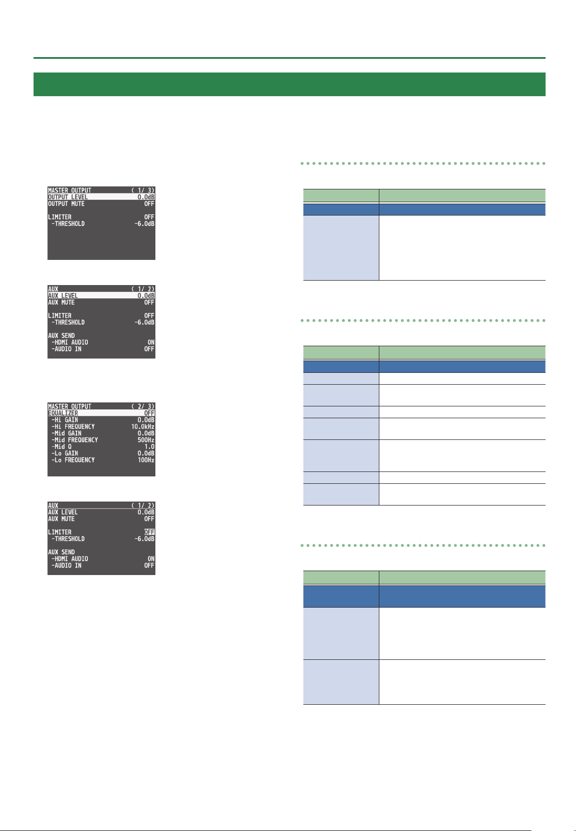
Audio Operations
Applying Eects to Output Audio
You can modify the tonal character by applying eects to the audio output.
* You can apply a limiter (LIMITER) to the audio of the AUX bus.
1. Press the [MENU] button0”AUDIO OUTPUT”0
select “MASTER OUTPUT” or “AUX,” and press the
[VALUE] knob.
(for AUX)
2. Turn the [VALUE] knob to select an eect menu
item, and then press the [VALUE] knob.
(for AUX)
LIMITER
This limits the output volume so that is does not exceed the set level.
Menu item Explanation
LIMITER Turn the limiter on or o.
Adjusts the level that becomes the threshold
at which the limiter is applied.
THRESHOLD
Compression is applied to audio that exceeds
the threshold. The volume level of audio that
is output is limited so as to stay to below the
threshold.
EQUALIZER
This limits the output volume so that is does not exceed the set level.
Menu item Explanation
EQUALIZER Turns the equalizer on/o.
Hi GAIN Boosts or attenuates the high band.
Hi FREQUENCY
Mid GAIN Boosts or attenuates the middle band.
Mid FREQUENCY
Mid Q
Lo GAIN Boosts or attenuates the low band.
Lo FREQUENCY
Species the center frequency when
changing the tone quality in the high band.
Species the center frequency when
changing the tone quality in the middle band.
Adjusts the width of the frequency band
when boosting or attenuating the middle
band.
Species the center frequency when
changing the tone quality in the low band.
3. Turn the [VALUE] knob to change the value, and
press the [VALUE] knob.
4. Press the [MENU] button to quit the menu.
32
MULTI BAND COMPRESSOR
This applies separate compressors in individual frequency bands.
Menu item Explanation
MULTI BAND
COMPRESSOR
Hi THRESHOLD
Mid THRESHOLD
Lo THRESHOLD
Hi RATIO
Mid RATIO
Lo RATIO
Turns the multi-band compressor on/o.
Specify the individual levels that become the
thresholds for the high, midrange, and low
bands at which the compressor is applied.
Compression is applied to audio that exceeds
the threshold.
Specify the amount of compression applied in
the high, midrange, and low bands.
The state in which no compression is applied
is dened as “1.”
Page 33
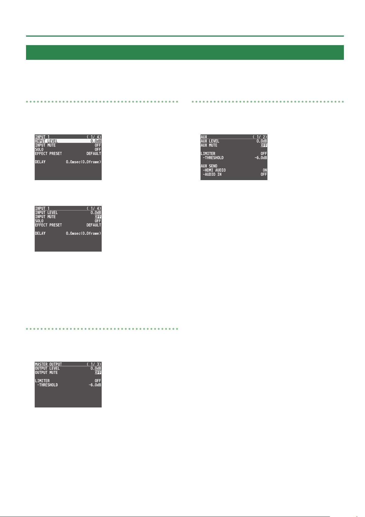
Silencing Only Specic Audio (Mute)
Here’s how to temporarily silence specic input audio or output audio (the mute function).
Audio Operations
Muting input audio
1. Press the [MENU] button0”AUDIO INPUT”0select
“INPUT 1”–“INPUT 8” or “AUDIO IN,” and press the
[VALUE] knob.
2. Turn the [VALUE] knob to select “INPUT MUTE,” and
press the [VALUE] knob.
3. Turn the [VALUE] knob to select “ON,” and press the
[VALUE] knob.
To cancel muting, specify “OFF.”
Muting AUX-bus Audio
1. Press the [MENU] button0”AUDIO OUTPUT”0
”AUX”0select “AUX MUTE,” and press the [VALUE]
knob.
2. Turn the [VALUE] knob to select “ON,” and press the
[VALUE] knob.
To cancel muting, specify “OFF.”
3. Press the [MENU] button to quit the menu.
4. Press the [MENU] button to quit the menu.
Muting output audio
1. Press the [MENU] button0”AUDIO OUTPUT”0
”MASTER OUTPUT”0select “OUTPUT MUTE,” and
press the [VALUE] knob.
2. Turn the [VALUE] knob to select “ON,” and press the
[VALUE] knob.
To cancel muting, specify “OFF.”
3. Press the [MENU] button to quit the menu.
33
Page 34
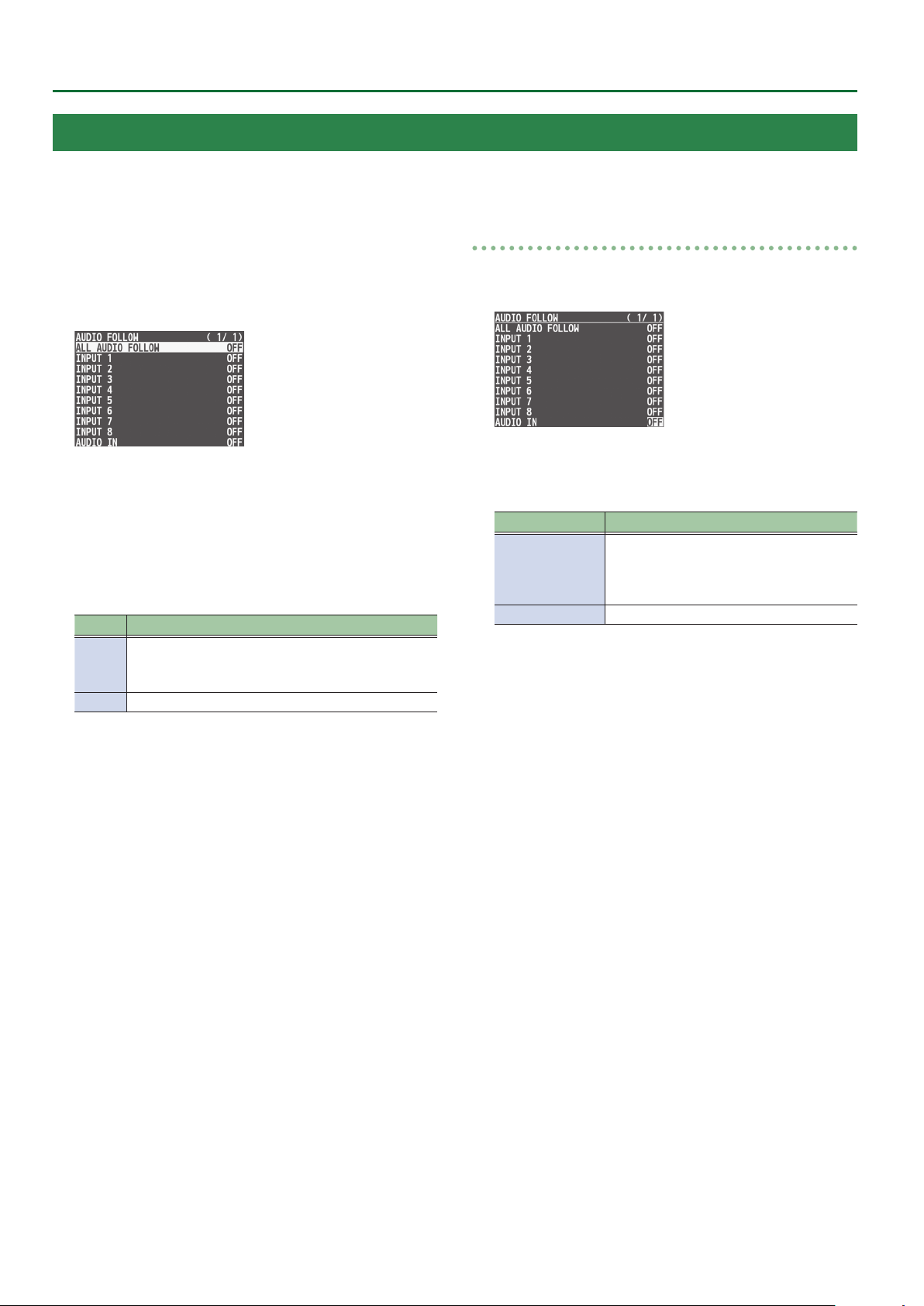
Audio Operations
Interlinking Audio Output to Video Switching (Audio Follow)
You can associate audio with a video switch so that when the video is switched, the specied audio alone is output automatically, and other audio
is automatically muted.
1. Follow the procedure in “Adjusting the Volume
Level” (p. 30) to adjust to the volume level you
want to output.
2. Press the [MENU] button0select “AUDIO FOLLOW,”
and press the [VALUE] knob.
3. Turn the [VALUE] knob to select the video channel
you want to use with Audio Follow, and press the
[VALUE] knob.
If you select “ALL AUDIO FOLLOW,” all input channels are used.
4. Turn the [VALUE] knob to select “ON,” and press the
[VALUE] knob.
Value Explanation
Enables the Audio Follow feature.
ON
OFF Disables the Audio Follow feature.
Muting is performed automatically when video on
another channel is output.
Applying audio follow to the audio from AUDIO IN
1. Press the [MENU] button0“AUDIO FOLLOW”0
select “AUDIO IN,” and press the [VALUE] knob.
2. Turn the [VALUE] knob to select the video channel
you want to use with Audio Follow, and press the
[VALUE] knob.
Value Explanation
Specify the input channels that use audio
INPUT 1–8
OFF Disables the Audio Follow feature.
3. Press the [MENU] button to quit the menu.
follow for the input audio.
The AUDIO IN audio is muted for input
channels other than those specied.
5. Press the [MENU] button to quit the menu.
6. Switch the video.
On video channels where Audio Follow is on, audio is
automatically muted when video on other channels is output.
34
Page 35
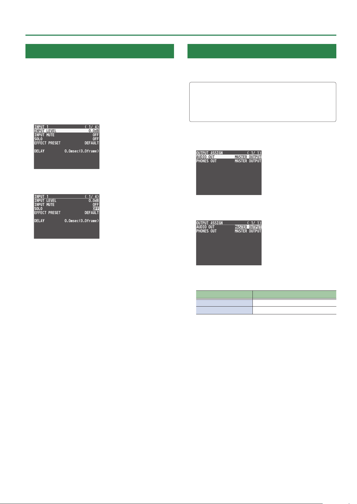
Audio Operations
Checking a Specic Audio Input (Solo)
Here’s how you can temporarily monitor a specic audio input via the
headphones (solo function).
* The solo function applies to the headphone output. It does not
aect output other than the headphones.
1. Press the [MENU] button0”AUDIO INPUT”0select
“INPUT 1”–“INPUT 8” or “AUDIO IN,” and press the
[VALUE] knob.
2. Turn the [VALUE] knob to select “SOLO,” and press
the [VALUE] knob.
Outputting AUX-Bus Audio
You can output just AUX-bus audio from the AUDIO OUT jacks
(XLR and RCA) and the PHONES jack.
What’s AUX-bus audio?
Video and audio on video input channels selected using the AUX
[1]–[8] buttons is sent to the AUX bus (p. 16).
If you assign the AUX bus to the audio output jacks, the audio sent
to the AUX bus is output.
1. Press the
select “OUTPUT ASSIGN,” and press the [VALUE] knob.
2. Turn the [VALUE] knob to select “AUDIO OUT” or
“PHONES OUT,” and press the [VALUE] knob.
[
MENU] button0“AUDIO OUTPUT”0
3. Turn the [VALUE] knob to select “ON,” and press the
[VALUE] knob.
4. Press the [MENU] button to quit the menu.
3. Turn the [VALUE] knob to select “AUX,” and press
the [VALUE] knob.
Value Explanation
MASTER OUT Output the audio of the MAIN bus.
AUX Output the audio of the AUX bus.
4. Press the [MENU] button to quit the menu.
35
Page 36
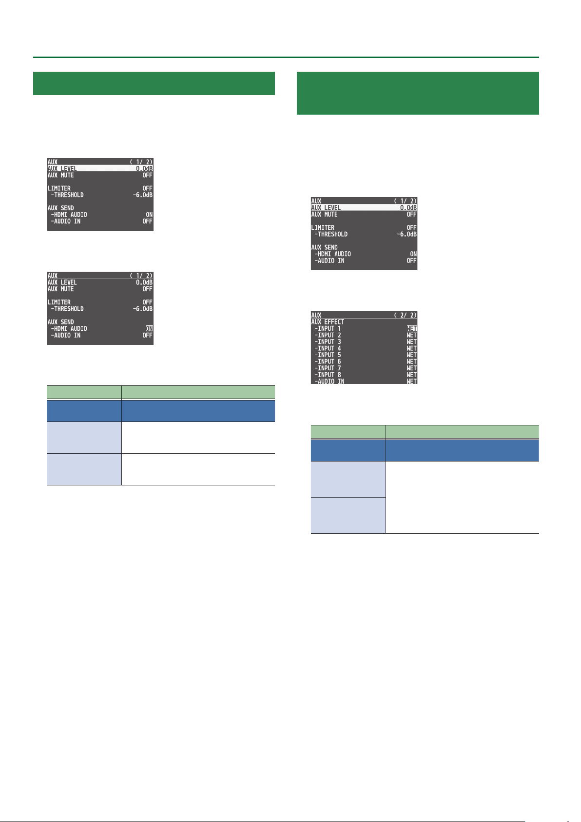
Audio Operations
Sending the AUDIO IN Audio to the AUX Bus
You can send the input audio of the AUDIO IN jacks to the AUX bus.
1. Press the [MENU] button0“AUDIO OUTPUT”0
select “AUX,” and press the [VALUE] knob.
2. Turn the [VALUE] knob to select the “AUX SEND”
menu item, and then press the [VALUE] knob.
3. Turn the [VALUE] knob to select “ON” or “OFF,” and
press the [VALUE] knob.
Menu item Explanation
AUX SEND
HDMI AUDIO
AUDIO IN
Species the audio that is sent to the AUX
bus.
Species whether the input audio of INPUT
1–8 is sent (ON) or is not sent (OFF) to the
AUX bus.
Species whether the input audio of the
AUDIO IN jacks is sent (ON) or is not sent
(OFF) to the AUX bus.
Specifying the Type of Audio Sent to the AUX Bus
When sending audio from INPUT 1–8 and AUDIO IN to the AUX bus,
you can specify whether to send the audio as-is or with an eect
applied.
1. Press the [MENU] button0“AUDIO OUTPUT”0
select “AUX,” and press the [VALUE] knob.
2. Turn the [VALUE] knob to select the “AUX EFFECT”
menu item, and then press the [VALUE] knob.
3. Turn the [VALUE] knob to select “DRY” or “WET,” and
press the [VALUE] knob.
Menu item Explanation
AUX EFFECT
INPUT 1–8
Species the type of audio that is sent
from each input to the AUX bus.
DRY:
Sends the source audio with no eects
applied.
4. Press the [MENU] button to quit the menu.
AUDIO IN
WET:
Sends the eect-applied audio.
4. Press the [MENU] button to quit the menu.
36
Page 37
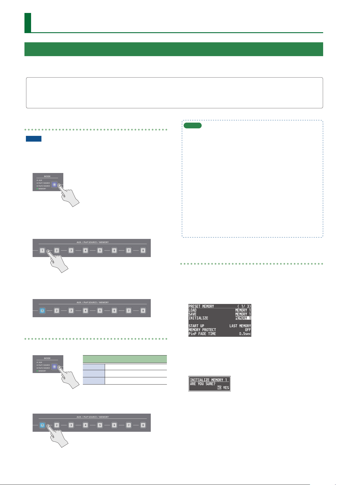
Other Features
Saving/Recalling Settings (Preset Memory)
You can save the current settings, including the video/audio settings and the state of the operating panel, in preset memory and recall those
settings for use when necessary. The V-8HD is provided with eight preset memories.
About the last memory function
The V-8HD has a built-in Last Memory function. Last Memory is a function that saves the state of the unit that is in eect immediately before
power-down, and automatically restores the state at the next startup. The Last Memory function is enabled by default. If you want the unit to
recall a specic preset memory when it starts up, use the PRESET MEMORY menu item “START UP” to specify the preset memory number.
Saving to a preset memory
NOTE
If “MEMORY PROTECT” (p. 60) is “ON,” you can’t save settings to a
preset memory.
1. Use the [MODE] button to select “MEMORY.”
2. Press and hold (for 2 seconds or longer) the MEMORY
button for the number where you want to save the
settings.
All of the MEMORY [1]–[8] buttons are briey illuminated in light
blue, and the current settings are saved in the selected preset
memory.
MEMO
5 The state of the [OUTPUT FADE] knob and [PHONES] knob are
not saved in preset memory.
5 The following settings are common to the unit (one set for the
entire unit), and therefore are not saved in preset memory.
– PRESET MEMORY menu
– CTL/EXP menu
– CAPTURE IMAGE menu
– SYSTEM menu
5 You can use the [MENU] button0“PRESET MEMORY”0“SAVE”
or “LOAD” to save or load a preset memory.
5 When recalling a preset memory, you can specify the individual
menu items that will be included in the recalled preset memory.
Make these settings in the PRESET MEMORY menu item “LOAD
PARAMETER.”
Initializing a preset memory
Here’s how you can initialize the settings of a specic preset memory
to the factory-set condition.
1. Press the [MENU] button0“PRESET MEMORY”0
select “INTIALIZE,” and press the [VALUE] knob.
Recalling a preset memory
1. Use the [MODE] button to select “MEMORY.”
MEMORY [1]–[8] button illumination color
Light blue Currently selected memory
Blue Memories in which data is saved
Unlit Memories with no data (empty)
2. Press the MEMORY button for the number whose
setting you want to recall.
The settings are recalled.
2. Turn the [VALUE] knob to select the preset memory
(MEMORY 1–8) that you want to initialize, and press
the [VALUE] knob.
A conrmation message appears.
* If you decide to cancel, press the [EXIT] button.
3. Turn the [VALUE] knob to select “YES,” and press the
[VALUE] knob.
The current settings are saved. When the operation is nished, the
message “COMPLETE” appears.
4. Press the [MENU] button to quit the menu.
37
Page 38
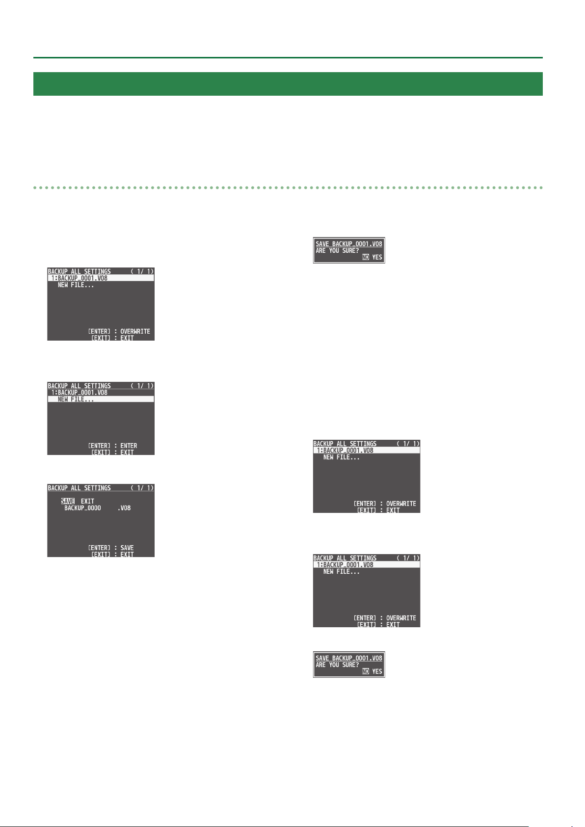
Other Features
Saving the Unit’s Settings on a USB Flash Drive
You can group together the unit’s settings into a single le (*.V08) and save it to a USB ash drive connected to the USB MEMORY port.
You can access the saved le (*.V08) on the USB ash drive and load it into the unit for use when needed.
* When you’re using a USB ash drive for the rst time, be sure to format it on the V-8HD (p. 39).
* Depending on the USB ash drive, recognition of the ash drive might take some time.
Saving
Saving a new settings le
1. Press the [MENU] button0“USB MEMORY”0
select “BACKUP ALL SETTINGS,” and press the
[VALUE] knob.
2. Turn the [VALUE] knob to select “NEW FILE...,” and
press the [VALUE] knob.
3. Enter the le name.
4. When you nish entering the name, turn the [VALUE]
knob to select “SAVE,” and press the [VALUE] knob.
A conrmation message appears.
* If you decide to cancel, press the [EXIT] button.
5. Press the [VALUE] knob.
The le (*.V08) is newly saved on the USB ash drive.
6. Press the [MENU] button to quit the menu.
Overwrite-saving a settings le
1. Press the [MENU] button0“USB MEMORY”0
select “BACKUP ALL SETTINGS,” and press the
[VALUE] knob.
1. Turn the [VALUE] knob to move the cursor.
Moving the cursor to a location where no character is present
increases the number of characters.
2. Turn the [VALUE] knob to highlight the character at the
cursor location.
3. Turn the [VALUE] knob to change the character, and press
the [VALUE] knob.
5 Pressing the [EXIT] button deletes the character at the cursor
location.
5 You can enter a text string of up to 9 characters in length.
5 The extension of the le name is “V08.”
38
2. Turn the [VALUE] knob select the le to overwrite,
and press the [VALUE] knob.
A conrmation message appears.
* If you decide to cancel, press the [EXIT] button.
3. Press the [VALUE] knob.
The le (*.V08) is newly saved on the USB ash drive.
4. Press the [MENU] button to quit the menu.
Page 39

Other Features
Recalling
This loads settings that are in a preset memory saved on a USB ash
drive. Loading settings overwrites the preset memory on the unit.
1. Press the [MENU] button0“USB MEMORY”0
select “RESTORE ALL SETTINGS,” and press the
[VALUE] knob.
2. Turn the [VALUE] knob to select the le you want to
recall, and press the [VALUE] knob.
A conrmation message appears.
* If you decide to cancel, press the [EXIT] button.
Formatting USB Flash Drives
When using a USB ash drive for the rst time, be sure to format it on
the V-8HD.
NOTE
5 The V-8HD does not recognize unformatted USB ash drives.
5 Performing formatting causes all data already saved on the USB
ash drive to be deleted. If the ash drive contains necessary data,
back it up onto a computer or elsewhere before formatting the
drive.
1. Press the [MENU] button0“USB MEMORY”0
select “FORMAT,” and press the [VALUE] knob.
3. Turn the [VALUE] knob to select “YES,” and press the
[VALUE] knob.
The settings are recalled, and the values in the unit’s preset
memories are overwritten.
4. Press the [MENU] button to quit the menu.
A conrmation message appears.
* If you decide to cancel, press the [EXIT] button.
2. Turn the [VALUE] knob to select “YES,” and press the
[VALUE] knob.
Formatting of the USB ash drive is carried out.
3. Press the [MENU] button to quit the menu.
39
Page 40
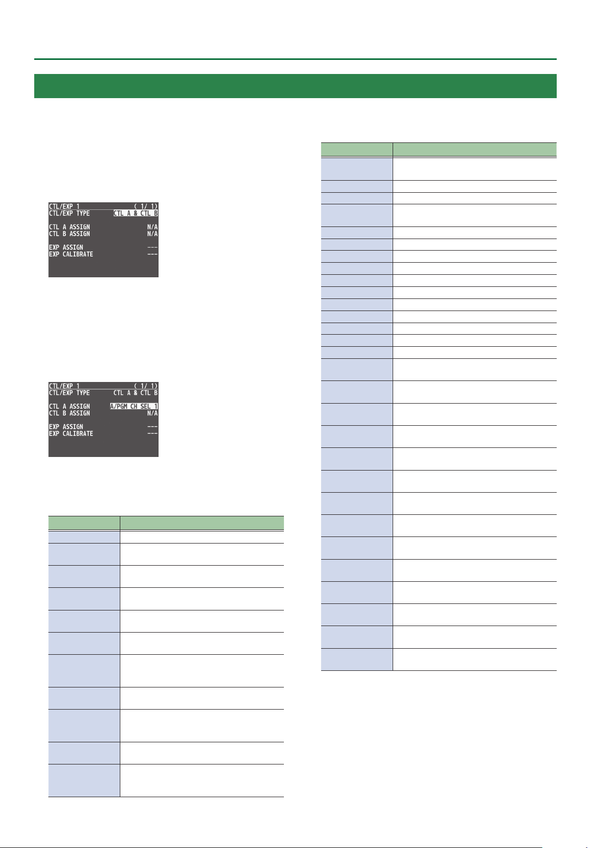
Other Features
Using a Footswitch
You can use a footswitch connected to the CTL/EXP 1, 2 jacks of the V-8HD to control the V-8HD with your foot.
You can assign various functions to the footswitch.
1. Connect a footswitch as described in p. 5.
2. Press the [MENU] button0“CTL/EXP”0select
“CTL/EXP 1” or “CTL/EXP 2,” and press the [VALUE]
knob.
3. Turn the [VALUE] knob to select “CTL TYPE,” and
press the [VALUE] knob.
4. Turn the [VALUE] knob to select “CTL A & CTL B,”
and press the [VALUE] knob.
5. Turn the [VALUE] knob to select “CTL A ASSIGN” or
“CTL B ASSIGN,” and press the [VALUE] knob.
6. Turn the [VALUE] knob to select the function
that you want to assign to CTL A or CTL B of the
footswitch, and press the [VALUE] knob.
Value Explanation
N/A No function is assigned.
A/PGM CH SEL
1–8
B/PST CH SEL 1–8
AUX CH SEL 1–8
INPUT 1–8
ASSIGN
STILL 1–8
OUTPUT
PinP 1 SRC HDMI
1–8
PinP 1 SRC STILL
1–8
PinP 2 SRC HDMI
1–8
PinP 2 SRC STILL
1–8
DSK SOURCE
HDMI 1–8
Selects the video of the specied input
channel as the video sent to the A/PGM bus.
Selects the video of the specied input
channel as the video sent to the B/PST bus.
Selects the video of the specied input
channel as the video sent to the AUX bus.
Switches the source of the specied input
channel.
Switches the output video to the specied
still image.
Switches the video shown in the PinP 1 inset
screen to the video of the specied input
channel.
Switches the video shown in the PinP 1 inset
screen to the specied still image.
Switches the video shown in the PinP 2 inset
screen to the video of the specied input
channel.
Switches the video shown in the PinP 2 inset
screen to the specied still image.
Switches the source image for DSK
compositing to the video of the specied
input channel.
Value Explanation
DSK SOURCE
STILL 1–8
CUT SW The same function as the [CUT] button.
AUTO SW The same function as the [AUTO] button.
TRANSITION SW
MODE SW The same function as the [MODE] button.
SPLIT/VFX A SW
SPLIT/VFX B SW
PinP 1 PVW SW
PinP 1 ON SW The same function as the PinP 1 [ON] button.
PinP 2 PVW SW
PinP 2 ON SW The same function as the PinP 2 [ON] button.
DSK PVW SW The same function as the DSK [PVW] button.
DSK ON SW The same function as the DSK [ON] button.
USER 1 SW The same function as the USER [1] button.
USER 2 SW The same function as the USER [2] button.
H AUTO TAKE I
H CUT I
INPUT 1–8 AUDIO
MUTE
AUDIO IN AUDIO
MUTE
AUDIO OUTPUT
MUTE
AUDIO AUX
MUTE
INPUT 1–8 AUDIO
SOLO
OUTPUT FADE
LEFT
OUTPUT FADE
RIGHT
LOAD MEMORY
1–8
INPUT SCAN
NORMAL
INPUT SCAN
REVERSE
MEMORY SCAN
NORMAL
MEMORY SCAN
REVERSE
Switches the source image for DSK
compositing to the specied still image.
The same function as the [TRANSITION]
button.
The same function as the SPLIT/VFX [A] button.
The same function as the SPLIT/VFX [B] button.
The same function as the PinP 1 [PVW] button.
The same function as the PinP 2 [PVW] button.
Switches the video between A/PGM bus and
B/PST bus.
Switches the video between A/PGM bus and
B/PST bus as a cut.
Turns the mute function on/o for the audio
of the specied input channel.
Turns the mute function on/o for AUDIO
IN audio.
Turns the mute function on/o for AUDIO
OUT audio.
Turns on/o the mute function for AUX-bus
audio.
Turns the solo function on/o for the audio
of the specied input channel.
The same function as turning the [OUTPUT
FADE] knob to the left.
The same function as turning the [OUTPUT
FADE] knob to the right.
Recalls the specied preset memory.
Consecutively switches the input video in the
order of INPUT 108 each time you press.
Consecutively switches the input video in the
order of INPUT 801 each time you press.
Consecutively switches the preset memory
in the order of 108 each time you press.
Consecutively switches the preset memory
in the order of 801 each time you press.
7. Press the [MENU] button to quit the menu.
40
Page 41

Using an Expression Pedal
You can use an expression pedal connected to the CTL/EXP 1, 2 jacks of the V-8HD to control the V-8HD with your foot.
Other Features
Adjusting the pedal (pedal calibration)
The rst time you use an expression pedal, you must calibrate (adjust)
the pedal so that it will operate optimally.
In some cases, an expression pedal might no longer operate
optimally due to the passage of time or changes in the operating
conditions. If you notice problems such as slight movements of the
pedal causing a major change in volume, or if the video fails to switch
when you press the pedal, you should execute calibration.
1. Press the [MENU] button0“CTL/EXP”0select
“CTL/EXP 1” or “CTL/EXP 2,” and press the [VALUE]
knob.
2. Turn the [VALUE] knob to select “CTL TYPE,” and
press the [VALUE] knob.
3. Turn the [VALUE] knob to select “EXP,” and press the
[VALUE] knob.
MEMO
You should normally use the EV-5 with its minimum volume knob
left in the zero position.
If you change the position of the minimum volume knob, you
must execute pedal calibration.
Assigning a function to the pedal
A variety of functions can be assigned to the expression pedal.
1. Press the [MENU] button0“CTL/EXP”0select
“CTL/EXP 1” or “CTL/EXP 2,” and press the [VALUE]
knob.
4. Turn the [VALUE] knob to select “EXP CALIBRATE,”
and press the [VALUE] knob.
The EXP CALIBRATE screen appears.
5. As directed by the screen, step on the pedal in the
fully heel-down position, and press the [VALUE]
knob.
6. As directed by the screen, step on the pedal in the
fully toe-down position, and press the [VALUE]
knob.
When the “Complete” indication appears, calibration is completed.
7. Press the [MENU] button to quit the menu.
2. Turn the [VALUE] knob to select “CTL/EXP TYPE,”
and press the [VALUE] knob.
3. Turn the [VALUE] knob to select “EXP,” and press the
[VALUE] knob.
4. Turn the [VALUE] knob to select “EXP ASSIGN,” and
press the [VALUE] knob.
5. Turn the [VALUE] knob to select the function that
you want to assign to the expression pedal, and
press the [VALUE] knob.
41
Page 42

Other Features
Value Explanation
N/A No function is assigned.
VIDEO FADER
H CUT I
VFX A MIX LEVEL
VFX B MIX LEVEL
OUTPUT FADE
LEFT
OUTPUT FADE
RIGHT
STILL 1–8
OUTPUT
INPUT 1–8 AUDIO
LEVEL
AUDIO IN AUDIO
LEVEL
AUDIO OUTPUT
LEVEL
AUX OUTPUT
LEVEL
Slides the video fader to the top edge or
bottom edge.
Switches the video between A/PGM bus and
B/PST bus as a cut.
Adjusts the density (output level) of the video
that is processed by the visual eect A.
Adjusts the density (output level) of the video
that is processed by the visual eect B.
Turns the [OUTPUT FADE] knob
counterclockwise.
Turns the [OUTPUT FADE] knob clockwise.
Switches the output video to the specied
still image.
Adjusts the volume of the specied input
channel.
Adjusts the volume of AUDIO IN.
Adjusts the volume of AUDIO OUT.
Adjusts the volume of AUX bus.
6. Press the [MENU] button to quit the menu.
Assigning the Functions of the USER [1] [2] Buttons
* With the factory settings, the freeze function is assigned to the
USER [1] button and the auto switching function is assigned to the
USER [2] button.
1. Press the [MENU] button0“SYSTEM”0select
“USER 1 SW ASSIGN” or “USER 2 SW ASSIGN,” and
press the [VALUE] knob.
2. Turn the [VALUE] knob to select the function that
you want to assign to the USER [1] or [2] button,
and then press the [VALUE] knob.
Value Explanation
N/A No function is assigned.
FREEZE Turns the freeze function on/o.
AUTO SWITCHING Turns the auto switching function on/o.
BPM TAP
INPUT 1–8 ASSIGN
STILL 1–8 OUTPUT Outputs the specied still image.
INPUT 1–8 MUTE
AUDIO IN MUTE
OUTPUT MUTE
AUX MUTE
INPUT SCAN N
INPUT SCAN R
MEMORY SCAN N
MEMORY SCAN R
REC START/STOP
If AUTO SWITCHING is “BPM SYNC,” you can
set the BPM by tapping the button.
Selects the video that is assigned to the
specied input.
Turns the mute function on/o for the
audio of the specied input channel.
Turns the mute function on/o for AUDIO
IN audio.
Turns on/o the mute function for AUDIO
OUT audio.
Turns on/o the mute function for AUXbus audio.
Consecutively switches the input video in
the order of INPUT 108 each time you
press.
Consecutively switches the input video in
the order of INPUT 801 each time you
press.
Consecutively switches the preset memory
in the order of 108 each time you press.
Consecutively switches the preset memory
in the order of 801 each time you press.
Controls the recorder's video record start/
stop if a recorder that supports HDMI REC
TRIGGER functionality is connected.
42
3. Press the [MENU] button to quit the menu.
Page 43

Other Features
Preventing Unintended Operation (Panel Lock)
Here’s how you can lock the V-8HD’s buttons and knobs to prevent
unintended operation.
1. Press the [MENU] button0“SYSTEM”0select
“PANEL LOCK,” and press the [VALUE] knob.
The PANEL LOCK menu appears.
2. Turn the [VALUE] knob to select a target for panel
lock, and press the [VALUE] knob.
Menu item Explanation
ALL SW & VOLUME
A/PGM 1–8 SW Cross-point A [1]–[8] buttons
B/PST 1–8 SW Cross-point B [1]–[8] buttons
CUT SW [CUT] button
AUTO SW [AUTO] button
MODE SW [MODE] button
AUX SW AUX [1]–[8] button
PinP 1 SOURCE SW PinP 1 [1]–[8] button
PinP 2 SOURCE SW PinP 2 [1]–[8] button
MEMORY SW MEMORY [1]–[8] button
TRANSITION SW [TRANSITION] button
VIDEO FADER Video fader
SPLIT/VFX A BLOCK SPLIT/VFX [A] knob/button
SPLIT/VFX A BLOCK SPLIT/VFX [B] knob/button
PinP 1 BLOCK
PinP 2 BLOCK
DSK BLOCK
USER 1 SW USER [1] button
USER 2 SW USER [2] button
CAPTURE IMAGE SW [CAPTURE IMAGE] button
OUTPUT FADE [OUTPUT FADE] knob
3. Turn the [VALUE] knob to specify whether panel
lock is applied (ON) or not applied (OFF), and press
the [VALUE] knob.
4. Repeat steps 2–3 as necessary.
5. Press the [MENU] button to quit the menu.
MEMO
When panel is locked, the [MENU] button is blink.
Turns on/o the settings of the following
buttons and knobs in a single action.
PinP 1’s [POSITION H] knob, [POSITION V]
knob, [PVW] button, [ON] button
PinP 2’s [POSITION H] knob, [POSITION V]
knob, [PVW] button, [ON] button
DSK’s [LEVEL] knob, [GAIN] knob,
[PVW] button, [ON] button
Controlling an External Recorder’s Video Record Start/Stop from the V-8HD
If a recorder that supports the “HDMI REC TRIGGER” function is
connected to an OUTPUT of the V-8HD, you can use the USER [1] or
[2] button of the V-8HD to control video record start/stop on that
recorder.
MEMO
For more about recorders that support the HDMI REC TRIGGER
function, refer to the Roland website.
https://proav.roland.com
1. Press the [MENU] button0“SYSTEM”0select
“USER 1 SW ASSIGN” or “USER 2 SW ASSIGN,” and
press the [VALUE] knob.
2. Turn the [VALUE] knob to select “REC START/STOP,”
and press the [VALUE] knob.
3. Press the [MENU] button to quit the menu.
4. Press the USER [1] or [2] button that is assigned to
“REC START/STOP.”
Each time you press the button, the recorder switches between
video record start/stop.
The USER [1] or [2] button is lit red during recording, and is unlit
when recording stops.
NOTE
The lit/unlit state of the USER [1] [2] buttons indicates the state of the
V-8HD, and does not reect the state of the external recorder.
This means that even if, while the USER [1] or [2] button is lit red, the
external recorder stops recording because of an operation performed
on it or because of the state of its storage, the USER [1] or [2] button
does not go dark at that time.
MEMO
If you want to disable control of the recorder that supports the HDMI
REC TRIGGER function, turn the VIDEO OUTPUT menu0OUTPUT 1–3
“REC CONTROL” setting “OFF.”
43
Page 44

Other Features
Returning to the Factory Settings (Factory Reset)
Here’s how you can return the settings of the V-8HD to their factoryset state. If following the procedures described in this manual does
not cause the result you expect, try executing a factory reset.
NOTE
5 When you execute factory reset, any previously specied content,
any settings saved in preset memory (p. 37), and the still image
(p. 26) saved in the unit will all be lost.
5 Do not turn o the power while the “PLEASE WAIT” message is
shown.
1. Press the [MENU] button0“SYSTEM”0select
“FACTORY RESET,” and press the [VALUE] knob.
A conrmation message appears.
* If you decide to cancel, press the [EXIT] button.
2. Turn the [VALUE] knob to select “YES,” and press the
[VALUE] knob.
The factory reset is executed.
When the operation is nished, the message “COMPLETE” appears.
3. Press the [MENU] button to quit the menu.
44
Page 45

Menu List
When you press the [MENU] button, the menu is shown on this unit’s monitor and on the display that’s connected to the OUTPUT 3 connector.
MEMO
5 When a setting value has menu items that let you make
more-detailed settings, “ENTER” is displayed at the top of
the screen. Press the [VALUE] knob to go down a level.
5 To execute an operation, press the [VALUE] knob.
5 You can change a setting value rapidly by holding down
the [VALUE] button and turning.
5 Long pressing the [EXIT] button returns the currently
selected setting to its default value.
1: VIDEO INPUT
INPUT 1–6
Menu item Value (Bold: default) Explanation
INPUT STATUS ENTER Displays information about the incoming video (format, size, etc.).
INPUT ASSIGN HDMI, STILL 1–8 Selects the input source.
FLIP H OFF, ON If this is “ON,” the video is input with left and right ipped.
FLIP V OFF, ON If this is “ON,” the video is input with top and bottom ipped.
BRIGHTNESS -64–0–63 Adjusts the brightness.
CONTRAST -64–0–63 Adjusts the contrast.
SATURATION -64–0–63 Adjusts the saturation.
INPUT 7, 8 (SCALER)
Menu item Value (Bold: default) Explanation
INPUT STATUS ENTER Displays information about the incoming video (format, size, etc.).
INPUT ASSIGN HDMI, STILL 1–8 Selects the input source.
FLICKER FILTER OFF, ON If this is “ON,” ickering is reduced.
FLIP H OFF, ON If this is “ON,” the video is input with left and right ipped.
FLIP V OFF, ON If this is “ON,” the video is input with top and bottom ipped.
INTERNAL
SVGA (800x600)
XGA (1024x768)
WXGA (1280x800)
FWXGA (1366x768)
EDID
ZOOM 10.0–100.0–1000.0% (*1) Adjusts the zoom ratio.
SXGA (1280x1024)
SXGA+(1400x1050)
UXGA (1600x1200)
WUXGA (1920x1200)
720/59.94p
1080/59.94i
1080/59.94p
Species the input format (EDID).
If this is “INTERNAL,” EDID information for all formats that can be input to the
V-8HD will be transmitted.
What is EDID?
EDID is data that is transmitted from the V-8HD to the source device when the
V-8HD is connected to a source device. EDID contains data such as the formats
that can be input to the V-8HD (resolution, color space, color depth) and audio
information.
Based on the EDID information that the source device receives, it will output
the most appropriate video format to the V-8HD.
45
Page 46

Menu List
Menu item Value (Bold: default) Explanation
Species the scaling type.
FULL
LETTERBOX
SCALING TYPE
CROP
DOT BY DOT Performs no scaling.
MANUAL Scale according to the “MANUAL SIZE H” and “MANUAL SIZE V” settings below.
MANUAL SIZE H (*2) -2000–0–2000 (*1) Adjusts the horizontal size.
MANUAL SIZE V (*2) -2000–0–2000 (*1) Adjusts the vertical size.
POSITION H -1920–0–1920 Adjusts the display position in the horizontal direction.
POSITION V -1920–0–1920 Adjusts the display position in the vertical direction.
BRIGHTNESS -64–0–63 Adjusts the brightness.
CONTRAST -64–0–63 Adjusts the contrast.
SATURATION -64–0–63 Adjusts the saturation.
RED -64–0–63 Adjusts the red level.
GREEN -64–0–63 Adjusts the green level.
BLUE -64–0–63 Adjusts the blue level.
Always displays the picture expanded to full screen, irrespective of the aspect
ratio of the input video.
Enlarges or reduces the incoming video to a full-screen view while keeping the
aspect ratio unchanged.
Enlarges or reduces the incoming video so that the output picture has no
blank margins while keeping the aspect ratio unchanged. Video extending
beyond the borders is cut o.
(*1) The valid range of setting values depends on conditions such as the input/output format.
(*2) This is valid when “SCALING TYPE” is set to “MANUAL.”
2: VIDEO OUTPUT
OUTPUT 1–3
Menu item Value (Bold: default) Explanation
OUTPUT STATUS —
Species the output bus that is assigned to the OUTPUT connector.
PROGRAM Outputs the program video.
OUTPUT ASSIGN
COLOR SPACE YPbPr, RGB (0–255), RGB (16–235) Species the color space.
DVI-D/HDMI SIGNAL HDMI, DVI-D Species the output mode for HDMI output.
BRIGHTNESS -64–0–63 Adjusts the brightness.
CONTRAST -64–0–63 Adjusts the contrast.
SATURATION -64–0–63 Adjusts the saturation.
RED -64–0–63 Adjusts the red level.
GREEN -64–0–63 Adjusts the green level.
BLUE -64–0–63 Adjusts the blue level.
REC CONTROL OFF, ON
PREVIEW Outputs the preview video (standby video).
AUX Outputs the AUX bus.
MULTI-VIEW Outputs the multi-view monitor.
Displays information about the output connector.
When there’s no connection, “NOT CONNECTED” is displayed.
Species whether video record start/stop on a recorder equipped with the
HDMI REC TRIGGER function will (ON) or will not (OFF) be controlled from the
V-8HD.
Default
OUTPUT 1: PROGRAM
OUTPUT 2: PREVIEW
OUTPUT 3: MULTI-VIEW
46
Page 47

3: TRANSITION TIME
Menu item Value (Bold: default) Explanation
MIX/WIPE TIME 0.0–1.0–4.0sec Species the video transition time.
PinP 1 TIME 0.0–1.0–4.0sec
PinP 2 TIME 0.0–1.0–4.0sec
DSK TIME 0.0–1.0–4.0sec
Species the fade time with which the PinP 1 or PinP 2 inset screen appears or
disappears when using Picture in Picture (PinP) compositing.
Species the fade time with which the superimposed logo or video appears or
disappears when using DSK compositing.
4: MIX/WIPE
Menu item Value (Bold: default) Explanation
TRANSITION TYPE MIX, WIPE
Species the transition pattern for mix.
MIX The two pictures are blended together as the video is switched.
MIX TYPE
FAM
NAM
Species the transition pattern for wipe.
HORIZONTAL VERTICAL UPPER LEFT UPPER RIGHT LOWER LEFT
Selects the mode of the transition eect.
You can also use the [TRANSITION] button to switch between MIX and WIPE.
Video transitions are made with the luminance levels of the two video streams
maintained unchanged.
This is an abbreviation of “full additive mix.”
The two video streams are compared, and transitions are made with display
during transition starting with levels of high luminance.
This is an abbreviation of “non-additive mix.”
Menu List
WIPE TYPE
LOWER RIGHT H-CENTER V-CENTER
WIPE DIRECTION NORMAL, REVERSE, ROUND TRIP Species the direction of wipe.
WIPE BORDER COLOR
WIPE BORDER WIDTH 0–3–14 Species the width of the border added to the edge of the wipe area.
WHITE, YELLOW, CYAN, GREEN,
MAGENTA, RED, BLUE, BLACK,
SOFTEDGE
Species the color of the border added to the edge of the wipe area.
If this is set to “SOFTEDGE,” the wipe border is blurred.
47
Page 48

Menu List
5: SPLIT/VFX
SPLIT/VFX A, B
Menu item Value (Bold: default) Explanation
SPLIT/VFX OFF, ON
SPLIT V, SPLIT H, PART MOSAIC,
BACKGROUND MOSAIC,
FULL MOSAIC, WAVE,
RGB REPLACE, COLORPASS,
SPLIT/VFX TYPE
9 SPLIT/VFX TYPE: SPLIT V Composites two videos split vertically at their centers.
Menu item Value (Bold: default) Explanation
A-CENTER -25.0–0.0–25.0%
B-CENTER -25.0–0.0–25.0%
CENTER POSITION -50.0–0.0–50.0%
BORDER COLOR
BORDER WIDTH 0–3–14 Adjusts the width of the border.
NEGATIVE, COLORIZE, POSTERIZE,
SILHOUETTE, EMBOSS,
FIND EDGES, MONOCOLOR,
HUE OFFSET, SATURATION OFFSET,
VALUE OFFSET
WHITE, YELLOW, CYAN, GREEN,
MAGENTA, RED, BLUE, BLACK
Turns the split/visual eect on/o.
You can also use the SPLIT/VFX [A] or [B] button to turn this on/o.
Species the split/visual eect types.
* The menu items dier for each split/visual eect.
Adjusts the horizontal position of the video shown on the left (A/PGM side).
You can adjust this by turning the SPLIT/VFX [A] knob.
Adjusts the horizontal position of the video shown on the right (B/PST side).
You can adjust this by turning the SPLIT/VFX [B] knob.
Adjusts the position of the boundary.
You can change the size of the two videos by shifting the boundary line.
You can adjust this by turning the SPLIT/VFX [A] or [B] knob while pressing it.
Species the color of the border.
9 SPLIT/VFX TYPE: SPLIT H Composites two videos split horizontally at their centers.
Menu item
A-CENTER -25.0–0.0–25.0%
B-CENTER -25.0–0.0–25.0%
CENTER POSITION -50.0–0.0–50.0%
BORDER COLOR
BORDER WIDTH 0–3 –14 Adjusts the width of the border.
9 SPLIT/VFX TYPE: PART MOSAIC Applies a mosaic to the selected region.
Menu item Value (Bold: default) Explanation
POSITION H -100.0–0.0–100.0%
POSITION V -100.0–0.0–100.0%
AREA SIZE 10.0–40.0–100.0% Adjusts the size (zoom) of the selected area.
CORRECTION H -2000–0–2000 Adjusts the horizontal size of the selected area.
CORRECTION V -2000–0–2000 Adjusts the vertical size of the selected area.
BLOCK SIZE
MIX LEVEL 0–255 Adjusts the intensity (output level) of the video with the visual eect applied.
Value (Bold: default)
WHITE, YELLOW, CYAN, GREEN,
MAGENTA, RED, BLUE, BLACK
OFF(1x1), 4x4, 8x8, 16x16, 32x32,
64x64, 128x128, 256x256
Explanation
Adjusts the vertical position of the video shown above (A/PGM side).
You can adjust this by turning the SPLIT/VFX [A] knob.
Adjusts the vertical position of the video shown above (B/PST side).
You can adjust this by turning the SPLIT/VFX [B] knob.
Adjusts the position of the boundary.
You can change the size of the two videos by shifting the boundary line.
You can adjust this by turning the SPLIT/VFX [A] or [B] knob while pressing it.
Species the color of the border.
Adjusts the horizontal position of the selected area.
You can adjust this by turning the SPLIT/VFX [A] or [B] knob.
Adjusts the vertical position of the selected area.
You can adjust this by turning the SPLIT/VFX [A] or [B] knob while pressing it.
Species the neness (block size) of the mosaic.
48
Page 49
Menu List
9 SPLIT/VFX TYPE: BACKGROUND MOSAIC Applies a mosaic to the portion of the selected area.
Menu item Value (Bold: default) Explanation
POSITION H -100.0–0.0–100.0%
POSITION V -100.0–0.0–100.0%
AREA SIZE 10.0–40.0–100.0% Adjusts the size (zoom) of the selected area.
CORRECTION H -2000–0–2000 Adjusts the horizontal size of the selected area.
CORRECTION V -2000–0–2000 Adjusts the vertical size of the selected area.
BLOCK SIZE
MIX LEVEL 0–255 Adjusts the intensity (output level) of the video with the visual eect applied.
9 SPLIT/VFX TYPE: FULL MOSAIC Applies a mosaic to the entire screen.
Menu item Value (Bold: default) Explanation
BLOCK SIZE
MIX LEVEL 0–255 Adjusts the intensity (output level) of the video with the visual eect applied.
OFF(1x1), 4x4, 8x8, 16x16, 32x32,
64x64, 128x128, 256x256
OFF(1x1), 4x4, 8x8, 16x16, 32x32,
64x64, 128x128, 256x256
Adjusts the horizontal position of the selected area.
You can adjust this by turning the SPLIT/VFX [A] or [B] knob.
Adjusts the vertical position of the selected area.
You can adjust this by turning the SPLIT/VFX [A] or [B] knob while pressing it.
Species the neness (block size) of the mosaic.
Species the neness (block size) of the mosaic.
9 SPLIT/VFX TYPE: WAVE Makes the video wavy.
Menu item Value (Bold: default) Explanation
GAIN 0–127–255 Adjust the height of the waves.
TYPE 1–4–7 Species the number of waves.
MIX LEVEL 0–255 Adjusts the intensity (output level) of the video with the visual eect applied.
9 SPLIT/VFX TYPE: RGB REPLACE Exchanges the colors.
Menu item Value (Bold: default) Explanation
TYPE
MIX LEVEL
9 SPLIT/VFX TYPE: COLOR PASS Turns the video black and white while preserving a specic color.
Menu item Value (Bold: default) Explanation
TYPE 1–42–63 Species the type of color pass.
MIX LEVEL
9 SPLIT/VFX TYPE: NEGATIVE Inverts the brightness and colors.
OFF(R.G.B), B.R.G, G.B.R, R.B.G,
G.R.B, B.G.R
0–255
0–255 Adjusts the intensity (output level) of the video with the visual eect applied.
Species the type of RGB replace.
Adjusts the intensity (output level) of the video with the visual eect applied.
Menu item Value (Bold: default) Explanation
TYPE Pr, Pb, PbPr, Y, YPr, YPb, YPbPr Species the type of negative.
MIX LEVEL
0–255
Adjusts the intensity (output level) of the video with the visual eect applied.
49
Page 50
Menu List
9 SPLIT/VFX TYPE: COLORIZE Adds color to the video.
Menu item Value (Bold: default) Explanation
TYPE
MIX LEVEL
9 SPLIT/VFX TYPE: POSTERIZE Changes the gradations in brightness.
Menu item Value (Bold: default) Explanation
LEVEL 1–3–4 Species the gradation level for brightness.
MIX LEVEL
1–8
0–255
0–255
Species the type of colorize.
Adjusts the intensity (output level) of the video with the visual eect applied.
Adjusts the intensity (output level) of the video with the visual eect applied.
9 SPLIT/VFX TYPE: SILHOUETTE
Menu item Value (Bold: default) Explanation
TYPE 1–128 Species the hue to be colorized.
MIX LEVEL 0–255
9 SPLIT/VFX TYPE: EMBOSS Adds a bas-relief eect to the video.
Menu item Value (Bold: default) Explanation
TYPE 1–128 Species the type of emboss.
CONTRAST 0–15 Adjusts the contrast.
MIX LEVEL 0–255
9 SPLIT/VFX TYPE: FIND EDGES Extracts contours.
Menu item Value (Bold: default) Explanation
FG COLOR 0–15 Species the color of the edge.
BG COLOR 0–3–15 Species the color of the background.
MIX LEVEL
0–255
Separates the video into light and dark areas, and makes the dark areas black
and adds a dierent color to the light areas.
Adjusts the intensity (output level) of the video with the visual eect applied.
Adjusts the intensity (output level) of the video with the visual eect applied.
Adjusts the intensity (output level) of the video with the visual eect applied.
9 SPLIT/VFX TYPE: MONOCOLOR Turns the video monochrome.
Menu item Value (Bold: default) Explanation
Pb COLOR 0–63 Species the color of the edge.
Pr COLOR 0–63 Species the color of the background.
MIX LEVEL
9 SPLIT/VFX TYPE: HUE OFFSET Changes the visual character by controlling the hue.
Menu item Value (Bold: default) Explanation
VALUE
MIX LEVEL
0–255
0–180–359
0–255
Adjusts the intensity (output level) of the video with the visual eect applied.
Species the reference value for hue.
Adjusts the intensity (output level) of the video with the visual eect applied.
50
Page 51

9 SPLIT/VFX TYPE: SATURATION OFFSET Changes the visual character by controlling the saturation.
Menu item Value (Bold: default) Explanation
VALUE
MIX LEVEL 0–255
9 SPLIT/VFX TYPE: VALUE OFFSET Changes the visual character by controlling the brightness.
Menu item Value (Bold: default) Explanation
VALUE
MIX LEVEL
-256–0–255
-256–0–255
0–255
Species the reference value for saturation.
Adjusts the intensity (output level) of the video with the visual eect applied.
Species the reference value for brightness.
Adjusts the intensity (output level) of the video with the visual eect applied.
Menu List
51
Page 52
Menu List
6: PinP
PinP 1, 2
Menu item Value (Bold: default) Explanation
Species the video source of the inset screen.
PinP SOURCE HDMI 1–8, STILL 1–8
PinP,
PinP TYPE
9 PinP TYPE: PinP Composites the video of the inset screen on top of the background video.
Menu item Value (Bold: default) Explanation
COPY SETTINGS FROM
PinP 2 (or PinP 1)
SWAP SETTINGS FROM
PinP 2 (or PinP 1)
WINDOW Adjusts the inset screen.
POSITION H -50.0–-40.0–50.0% Adjusts the inset screen’s display position horizontally.
POSITION V -50.0–-40.0–50.0% Adjusts the inset screen’s display position vertically.
SIZE 10.0–35.0–100.0% Adjusts the size (zoom) of the inset screen.
CROPPING H 0.0–100.0% Adjusts the horizontal size of the inset screen.
CROPPING V 0.0–100.0% Adjusts the vertical size of the inset screen.
SHAPE RECTANGLE, CIRCLE, DIAMOND Species the shape of the inset screen.
BORDER COLOR
BORDER WIDTH 0–3–14 Adjusts the width of the border for the inset screen.
VIEW Adjusts the video that is shown in the inset screen.
POSITION H -50.0–0.0–50.0% Adjusts the horizontal position at which the inset screen is shown.
POSITION V -50.0–0.0–50.0% Adjusts the vertical position at which the inset screen is shown.
ZOOM 100.0–1000.0% Adjusts the zoom of the inset screen.
LUMINANCE-WHITE KEY,
LUMINANCE-BLACK KEY,
CHROMA KEY
EXEC Copies another PinP settings.
EXEC Exchanges the settings of PinP 1 and PinP 2.
WHITE, YELLOW, CYAN, GREEN,
MAGENTA, RED, BLUE, BLACK,
SOFTEDGE
If MODE is “PinP 1 SOURCE” or “PinP 2 SOURCE,” you can also use the PinP
SOURCE [1]–[8] buttons to switch this.
Species the type of PinP compositing.
* The menu items dier for each type.
Species the color of the border for the inset screen.
If this is set to “SOFTEDGE,” the edge of the inset screen is blurred.
9 PinP TYPE: LUMINANCE-WHITE KEY
Menu item Value (Bold: default) Explanation
COPY SETTINGS FROM
PinP 2 (or PinP 1)
SWAP SETTINGS FROM
PinP 2 (or PinP 1)
WINDOW Adjusts the inset screen.
POSITION H -50.0–-40.0–50.0% Adjusts the inset screen’s display position horizontally.
POSITION V -50.0–-40.0–50.0% Adjusts the inset screen’s display position vertically.
SIZE 10.0–35.0–100.0% Adjusts the size (zoom) of the inset screen.
CROPPING H 0.0–100.0% Adjusts the horizontal size of the inset screen.
CROPPING V 0.0–100.0% Adjusts the vertical size of the inset screen.
VIEW Adjusts the video that is shown in the inset screen.
POSITION H -50.0–0.0–50.0% Adjusts the horizontal position at which the inset screen is shown.
POSITION V -50.0–0.0–50.0% Adjusts the vertical position at which the inset screen is shown.
ZOOM 100.0–1000.0% Adjusts the zoom of the inset screen.
EXEC Copies another PinP settings.
EXEC Exchanges the settings of PinP 1 and PinP 2.
Composites the video by applying a luminance key to the PinP to make its
white areas transparent.
52
Page 53
Menu List
Menu item Value (Bold: default) Explanation
KEY LEVEL 0–64–255 Adjusts the degree of extraction (transparency) for the key.
KEY GAIN 0–255 Adjusts the degree of edge blur (semi-transmissive region) for the key.
MIX LEVEL 0–255 Adjusts the key’s overall density (output level).
If this is “MATTE,” the superimposed logo or video is lled-in with the specied
FILL TYPE BUS, MATTE
MATTE COLOR
EDGE TYPE
EDGE COLOR
EDGE WIDTH 0–3–14 Species the width of the edge applied to the superimposed logo or video.
WHITE, YELLOW, CYAN, GREEN,
MAGENTA, RED, BLUE, BLACK
OFF, BORDER, DROP, SHADOW,
OUTLINE
WHITE, YELLOW, CYAN, GREEN,
MAGENTA, RED, BLUE, BLACK
color when using key compositing.
The ll-in color is specied by “MATTE COLOR” listed below.
Species the color used when lling-in the superimposed logo or video.
* This is valid when “FILL TYPE” is set to “MATTE.”
Species the type of edge applied to the superimposed logo or video.
Species the color of the edge applied to the superimposed logo or video.
9 PinP TYPE: LUMINANCE-BLACK KEY
Menu item
COPY SETTINGS FROM
PinP 2 (or PinP 1)
SWAP SETTINGS FROM
PinP 2 (or PinP 1)
WINDOW
POSITION H
POSITION V
SIZE
CROPPING H
CROPPING V
VIEW
POSITION H
POSITION V
ZOOM
KEY LEVEL
KEY GAIN
MIX LEVEL
FILL TYPE
MATTE COLOR
EDGE TYPE
EDGE COLOR
EDGE WIDTH
Value (Bold: default)
EXEC Copies another PinP settings.
EXEC Exchanges the settings of PinP 1 and PinP 2.
Adjusts the inset screen.
-50.0–-40.0–50.0% Adjusts the inset screen’s display position horizontally.
-50.0–-40.0–50.0% Adjusts the inset screen’s display position vertically.
10.0–35.0–100.0% Adjusts the size (zoom) of the inset screen.
0.0–100.0% Adjusts the horizontal size of the inset screen.
0.0–100.0% Adjusts the vertical size of the inset screen.
Adjusts the video that is shown in the inset screen.
-50.0–0.0–50.0% Adjusts the horizontal position at which the inset screen is shown.
-50.0–0.0–50.0% Adjusts the vertical position at which the inset screen is shown.
100.0–1000.0% Adjusts the zoom of the inset screen.
0–64–255 Adjusts the degree of extraction (transparency) for the key.
0–255 Adjusts the degree of edge blur (semi-transmissive region) for the key.
0–255 Adjusts the key’s overall density (output level).
BUS, MATTE
WHITE, YELLOW, CYAN, GREEN,
MAGENTA, RED, BLUE, BLACK
OFF, BORDER, DROP, SHADOW,
OUTLINE
WHITE, YELLOW, CYAN, GREEN,
MAGENTA, RED, BLUE, BLACK
0–3–14 Species the width of the edge applied to the superimposed logo or video.
Composites the video by applying a luminance key to the PinP to make its
black areas transparent.
Explanation
If this is “MATTE,” the superimposed logo or video is lled-in with the specied
color when using key compositing.
The ll-in color is specied by “MATTE COLOR” listed below.
Species the color used when lling-in the superimposed logo or video.
* This is valid when “FILL TYPE” is set to “MATTE.”
Species the type of edge applied to the superimposed logo or video.
Species the color of the edge applied to the superimposed logo or video.
53
Page 54
Menu List
9 PinP TYPE: CHROMA KEY Composites the video by applying chroma key to the PinP.
Menu item Value (Bold: default) Explanation
COPY SETTINGS FROM
PinP 2 (or PinP 1)
SWAP SETTINGS FROM
PinP 2 (or PinP 1)
WINDOW Adjusts the inset screen.
POSITION H -50.0–-40.0–50.0% Adjusts the inset screen’s display position horizontally.
POSITION V -50.0–-40.0–50.0% Adjusts the inset screen’s display position vertically.
SIZE 10.0–35.0–100.0% Adjusts the size (zoom) of the inset screen.
CROPPING H 0.0–100.0% Adjusts the horizontal size of the inset screen.
CROPPING V 0.0–100.0% Adjusts the vertical size of the inset screen.
VIEW Adjusts the video that is shown in the inset screen.
POSITION H -50.0–0.0–50.0% Adjusts the horizontal position at which the inset screen is shown.
POSITION V -50.0–0.0–50.0% Adjusts the vertical position at which the inset screen is shown.
ZOOM 100.0–1000.0% Adjusts the zoom of the inset screen.
KEY LEVEL 0–64–255 Adjusts the degree of extraction (transparency) for the key.
KEY GAIN 0–255 Adjusts the degree of edge blur (semi-transmissive region) for the key.
MIX LEVEL 0–255 Adjusts the key’s overall density (output level).
CHROMA Make detailed settings for chroma key.
COLOR GREEN, BLUE
HUE WIDTH -30–0–30 Adjusts the hue width for the key color.
HUE FINE 0–240–360 Adjusts the center position of the hue for the key color.
SATURATION WIDTH -30–0–30 Adjusts the saturation width for the key color.
SATURATION FINE 0–255 Adjusts the center position of saturation for the key color.
SAMPLING MARKER OFF, ON
POSITION H -50–0–50% Adjusts the horizontal position of the sampling marker.
POSITION V -50–0–50% Adjusts the vertical position of the sampling marker.
SAMPLING EXECUTE EXEC
FILL TYPE BUS, MATTE
MATTE COLOR
EDGE TYPE
EDGE COLOR
EDGE WIDTH 0–3–14 Species the width of the edge applied to the superimposed logo or video.
EXEC Copies the another PinP settings.
EXEC Exchanges the settings of PinP 1 and PinP 2.
Sets green or blue as the key color (the color to be removed). If you want a
color other than green or blue to turn transparent, use “SAMPLING MARKER” to
specify the key color.
If this is “ON,” a sampling marker (cross-shaped cursor) is shown on the preview
output video for you to sample (detect) the key color.
When you execute sampling, the setting automatically turns “OFF.”
Executes key color sampling.
The “HUE WIDTH,” “HUE FINE,” “SATURATION WIDTH,” and “SATURATION FINE”
settings are adjusted automatically.
If this is “MATTE,” the superimposed logo or video is lled-in with the specied
color when using key compositing.
The ll-in color is specied by “MATTE COLOR” listed below.
WHITE, YELLOW, CYAN, GREEN,
MAGENTA, RED, BLUE, BLACK
OFF, BORDER, DROP, SHADOW,
OUTLINE
WHITE, YELLOW, CYAN, GREEN,
MAGENTA, RED, BLUE, BLACK
Species the color used when lling-in the superimposed logo or video.
* This is valid when “FILL TYPE” is set to “MATTE.”
Species the type of edge applied to the superimposed logo or video.
Species the color of the edge applied to the superimposed logo or video.
54
Page 55

Menu List
7: DSK
Menu item Value (Bold: default) Explanation
DSK SOURCE HDMI 1–8, STILL 1–8 Select the source of the logo or image that you want to superimpose.
Species the DSK type used during DSK composition.
LUMINANCE-WHITE
DSK TYPE
DSK LEVEL 0–64–255 Adjusts the degree of extraction (transparency) for the key.
DSK GAIN 0–255 Adjusts the degree of edge blur (semi-transmissive region) for the key.
MIX LEVEL 0–255 Adjusts the key’s overall density (output level).
CHROMA
COLOR GREEN, BLUE
HUE WIDTH -30–0–30 Adjusts the hue width for the key color.
HUE FINE 0–240–360 Adjusts the center position of the hue for the key color.
SATURATION WIDTH -30–0–30 Adjusts the saturation width for the key color.
SATURATION FINE 0–255 Adjusts the center position of saturation for the key color.
SAMPLING MARKER OFF, ON
POSITION H -50–0–50% Adjusts the horizontal position of the sampling marker.
POSITION V -50–0–50% Adjusts the vertical position of the sampling marker.
SAMPLING EXECUTE EXEC
FILL TYPE BUS, MATTE
MATTE COLOR
EDGE TYPE
EDGE COLOR
EDGE WIDTH 0–3–14 Species the width of the edge applied to the superimposed logo or video.
LUMINANCE-BLACK
CHROMA
Make detailed settings for chroma key.
* This is valid when “DSK TYPE” is set to “CHROMA.”
WHITE, YELLOW, CYAN, GREEN,
MAGENTA, RED, BLUE, BLACK
OFF, BORDER, DROP, SHADOW,
OUTLINE
WHITE, YELLOW, CYAN, GREEN,
MAGENTA, RED, BLUE, BLACK
Composite using luminance key.
Makes white portions transparent according to brightness.
Composite using luminance key.
Makes black portions transparent according to brightness.
Composite using chroma key.
Makes the specied key color transparent according to hue.
Sets green or blue as the key color (the color to be removed). If you want a
color other than green or blue to turn transparent, use “SAMPLING MARKER” to
specify the key color.
If this is “ON,” a sampling marker (cross cursor) is shown on the preview output
video for you to sample (detect) the key color.
When you execute sampling, the setting automatically turns “OFF.”
Executes key color sampling.
The “HUE WIDTH,” “HUE FINE,” “SATURATION WIDTH,” and “SATURATION FINE”
settings are adjusted automatically.
If this is “MATTE,” the superimposed logo or video is lled-in with the specied
color when using key compositing.
The ll-in color is specied by “MATTE COLOR” listed below.
Species the color used when lling-in the superimposed logo or video.
* This is valid when “FILL TYPE” is set to “MATTE.”
Species the type of edge applied to the superimposed logo or video.
Species the color of the edge applied to the superimposed logo or video.
55
Page 56
Menu List
8: AUDIO INPUT
INPUT1–8, AUDIO INPUT
Menu item Value (Bold: default) Explanation
INPUT LEVEL -INF–0.0–10.0dB Adjusts the input volume.
INPUT MUTE OFF, ON
SOLO OFF, ON
Species an eect preset (high-pass lter, compressor, equalizer).
* When you change a preset, the settings of each eect are overwritten.
DEFAULT For line input (default setting)
MEETING For meetings
EFFECT PRESET
DELAY
HIGH PASS FILTER 75Hz OFF, ON
NOISE GATE OFF, ON
THRESHOLD -80.0–-50.0–0.0dB
RELEASE 30–380–5000ms
COMPRESSOR OFF, ON
THRESHOLD -80.0–-50.0–0.0dB
RATIO
ATTAC K 0.2–1–100ms
RELEASE 30–380–5000ms
AUTO GAIN OFF, ON
MAKEUP GAIN -40–0–40dB Adjusts the nal output volume after applying the compressor.
INTERVIEW For interviews
AMBIENT MIC For capturing ambient sound
WINDY FIELD For capturing ambient sound in a windy area
DE-ESS & POPS SOFT
DE-ESS & POPS HARD For reducing plosives
0.0–500.0msec
(0.0–29.9/25.0frame)
1.00: 1, 1.12: 1, 1.25: 1, 1.40: 1,
1.60: 1, 1.80: 1, 2.00: 1, 2.50: 1,
3.20: 1, 4.00: 1, 5.60: 1, 8.00: 1,
16.0: 1, INF: 1
Turns the mute function on/o. If this is “ON,” the input audio is temporarily
silenced.
Turns the solo function on/o. Only the audio for which this is “ON” is heard in
the headphones.
* The solo function applies to the headphone output. It does not aect output
other than the headphones.
For reducing sibilants
Adjusts the delay time of the audio.
Eect This outputs audio with a delay.
Turns the high-pass lter on/o.
Eect Cuts o unneeded low-band audio. The cuto frequency is 75 Hz.
Turns the noise gate on/o.
Eect This mutes audio that is below a specied level.
Species the level used as the threshold for removing audio. Audio below the
level set here is removed.
Adjusts the length of time until the audio is fully attenuated after audio falls
below the threshold.
Turns the compressor on/o.
Eect This compresses audio that exceeds a specied level.
Species the level used as the threshold at which the compressor is applied.
Compression is applied to audio that exceeds the threshold.
Species the degree of compression applied to the audio. The state in which
no compression is applied is dened as “1.”
Species the time until compression starts when audio exceeding the
threshold is input.
Adjusts the length of time until compression ends after audio falls below the
threshold.
Turns the auto makeup gain feature on/o.
If this is “ON,” the nal output volume level after applying the compressor is
automatically adjusted according to the “THRESHOLD” and “RATIO” settings.
The total of the “MAKEUP GAIN” setting value described below and the value
calculated by auto makeup gain becomes the nal output volume level
(up to +34 dB).
56
Page 57

Menu item Value (Bold: default) Explanation
EQUALIZER OFF, ON
Hi GAIN -15.0–0.0–15.0dB Boosts or attenuates the high band.
Hi FREQUENCY 1.0–10.0–20.0kHz Species the center frequency when changing the tone in the high band.
Mid GAIN -15.0–0.0–15.0dB Boosts or attenuates the middle band.
Mid FREQUENCY 20.0–500Hz–20.0kHz Species the center frequency when changing the tone in the middle band.
Mid Q 0.5–1.0–16.0
Lo GAIN -15.0–0.0–15.0dB Boosts or attenuates the low band.
Lo FREQUENCY 20.0–500Hz–20.0kHz Species the center frequency when changing the tone in the low band.
Turns the equalizer on/o.
Eect Adjusts the tone for each frequency band.
Adjusts the width of the frequency band when boosting or attenuating the
middle band.
Menu List
57
Page 58

Menu List
9: AUDIO OUTPUT
OUTPUT ASSIGN
Menu item Value (Bold: default) Explanation
Species the audio bus assigned to the AUDIO OUT jacks.
AUDIO OUT
PHONES OUT
MASTER OUTPUT
MASTER OUTPUT Output the audio of the MAIN bus.
AUX Output the audio of the AUX bus.
Species the audio bus assigned to the PHONES jack.
MASTER OUTPUT Output the audio of the MAIN bus.
AUX Output the audio of the AUX bus.
Menu item
OUTPUT LEVEL -INF–0.0–10.0dB Adjusts the output volume.
OUTPUT MUTE OFF, ON
LIMITER OFF, ON
THRESHOLD 30–380–5000ms
EQUALIZER OFF, ON
Hi GAIN -15.0–0.0–15.0dB Boosts or attenuates the high band.
Hi FREQUENCY 1.0–10.0–20.0kHz Species the center frequency when changing the tone in the high band.
Mid GAIN -15.0–0.0–15.0dB Boosts or attenuates the middle band.
Mid FREQUENCY 20.0–500Hz–20.0kHz Species the center frequency when changing the tone in the middle band.
Mid Q 0.5–1.0–16.0
Lo GAIN -15.0–0.0–15.0dB Boosts or attenuates the low band.
Lo FREQUENCY 20.0–500Hz–20.0kHz Species the center frequency when changing the tone in the low band.
MULTI BAND
COMPRESSOR
Hi THRESHOLD -40.0–-20.0–0.0dB
Hi RATIO
Mid THRESHOLD -40.0–-16.0–0.0dB
Mid RATIO
Lo THRESHOLD -40.0–-20.0–0.0dB
Lo RATIO
Value (Bold: default)
OFF, ON
1.00: 1, 1.12: 1, 1.25: 1, 1.40: 1,
1.60: 1, 1.80: 1, 2.00: 1, 2.50: 1,
3.20: 1, 4.00: 1, 5.60: 1, 8.00: 1,
16.0: 1, INF: 1
1.00: 1, 1.12: 1, 1.25: 1, 1.40: 1,
1.60: 1, 1.80: 1, 2.00: 1, 2.50: 1,
3.20: 1, 4.00: 1, 5.60: 1, 8.00: 1,
16.0: 1, INF: 1
1.00: 1, 1.12: 1, 1.25: 1, 1.40: 1,
1.60: 1, 1.80: 1, 2.00: 1, 2.50: 1,
3.20: 1, 4.00: 1, 5.60: 1, 8.00: 1,
16.0: 1, INF: 1
Explanation
Turns the mute function on/o.
If this is “ON,” the output audio is temporarily silenced.
Turns the limiter on or o.
Eect This limits the output volume so that is does not exceed the set level.
Adjusts the level that becomes the threshold at which the limiter is applied.
Compression is applied to audio that exceeds the threshold. The volume level
of audio that is output is limited so as to stay to below the threshold.
Turns the equalizer on/o.
Eect Adjusts the tone for each frequency band.
Adjusts the width of the frequency band when boosting or attenuating the
middle band.
Turns the multi-band compressor on/o.
Eect Applies separate compressors in individual frequency band.
Species the threshold level at which the compressor is applied to the high
band.
Compression is applied to audio that exceeds the threshold.
Species the amount of compression applied in the high band.
The state in which no compression is applied is dened as “1.”
Species the threshold level at which the compressor is applied to the middle
band.
Compression is applied to audio that exceeds the threshold.
Species the amount of compression applied in the middle band.
The state in which no compression is applied is dened as “1.”
Species the threshold level at which the compressor is applied to the low band.
Compression is applied to audio that exceeds the threshold.
Species the amount of compression applied in the low band.
The state in which no compression is applied is dened as “1.”
58
Page 59

AUX
Menu item Value (Bold: default) Explanation
AUX LEVEL -INF–0.0–10.0dB Adjusts the output volume of the AUX bus.
AUX MUTE OFF, ON
LIMITER OFF, ON
THRESHOLD 30–380–5000ms
AUX SEND Species the audio that is sent to the AUX bus.
HDMI AUDIO OFF, ON
AUDIO IN OFF, ON
AUX EFFECT Species the type of audio that is sent from each input to the AUX bus.
INPUT 1 DRY, WET
INPUT 2 DRY, WET
INPUT 3 DRY, WET
INPUT 4 DRY, WET
INPUT 5 DRY, WET
INPUT 6 DRY, WET
INPUT 7 DRY, WET
INPUT 8 DRY, WET
AUDIO IN DRY, WET
Turns the mute function on/o.
If this is “ON,” the output audio of the AUX bus is temporarily silenced.
Turn the limiter on/o.
Eect This limits the output volume so that is does not exceed the set level.
Adjusts the level that becomes the threshold at which the limiter is applied.
Compression is applied to audio that exceeds the threshold. The volume level
of audio that is output is limited so as to stay to below the threshold.
Species whether the input audio of INPUT 1–8 is sent (ON) or is not sent (OFF)
to the AUX bus.
Species whether the input audio of the AUDIO IN jacks is sent (ON) or is not
sent (OFF) to the AUX bus.
DRY:
Sends the source audio with no eects applied.
WET:
Sends the eect-applied audio.
Menu List
10: AUDIO FOLLOW
Menu item Value (Bold: default) Explanation
ALL AUDIO FOLLOW OFF, ON Turns on/o the audio follow function for INPUT 1–8 in a single action.
INPUT 1 OFF, ON
INPUT 2 OFF, ON
INPUT 3 OFF, ON
INPUT 4 OFF, ON
INPUT 5 OFF, ON
INPUT 6 OFF, ON
INPUT 7 OFF, ON
INPUT 8 OFF, ON
AUDIO IN OFF, INPUT 1–8
Turns the Audio Follow feature on/o.
Audio follow is a function that automatically switches the audio output in
tandem with video switching.
If this is “ON,” only the audio of the selected input video is output, and audio of
the other input video is automatically muted.
Species the input video (INPUT 1–8) that uses audio follow for the audio of
AUDIO IN.
The audio of AUDIO IN is output only when the specied input video is
selected.
If this is “OFF,” the audio of AUDIO IN is always output regardless of the input
video selection.
59
Page 60

Menu List
11: PRESET MEMORY
Menu item Value (Bold: default) Explanation
LOAD MEMORY 1–8
SAVE MEMORY 1–8
INITIALIZE MEMORY 1–8
Species the settings loaded at startup.
START UP
MEMORY PROTECT OFF, ON
PinP FADE TIME 0.0–0.5–1.0sec
LOAD PARAMETER Species the menu items that are applied when a preset memory is recalled.
VIDEO INPUT OFF, ON
VIDEO OUTPUT OFF, ON
TRANSITION TIME OFF, ON
MIX/WIPE OFF, ON
SPLIT/VFX OFF, ON
PinP OFF, ON
DSK OFF, ON
AUDIO INPUT OFF, ON
AUDIO OUTPUT OFF, ON
AUDIO FOLLOW OFF, ON
LAST MEMORY
MEMORY 1–8 Recall the settings at the selected memory number.
Selects the preset memory to load.
Pressing the [VALUE] knob lets you load the preset memory.
Selects a preset memory for saving settings.
Pressing the [VALUE] knob lets you save the settings to the preset memory.
* The state of the [PHONES] knob (headphone volume) is not saved in preset
memory.
* The following settings are common to the unit (one set for the entire unit),
and therefore are not saved in preset memory.
5 PRESET MEMORY menu
5 CTL/EXP menu
5 CAPTURE IMAGE menu
5 SYSTEM menu
Selects the preset memory to be initialized.
Press the [VALUE] knob to initialize the preset memory.
Restores the state that was in eect immediately before the power was turned
o (Last Memory function).
The current settings (Last Memory values) are saved every 4 seconds, and
when you exit a menu.
If this is “ON,” the preset memories are protected, and settings cannot be saved
to them.
Species the time over which the PinP 1 or PinP 2 inset screen disappears/
appears when a preset memory is recalled.
* If this is set to “0.0sec,” the PinP inset screen video might icker briey when a
preset memory is recalled.
Menu items for which this is “OFF” do not change when a preset memory is
recalled.
12: STILL IMAGE
Menu item Value (Bold: default) Explanation
Loads a still image from a USB ash drive and saves it in this unit.
Species the save-destination for the still image that is loaded from the USB
ash drive.
LOAD FROM USB
MEMORY
DELETE STILL IMAGE STILL 1–8
STILL 1–8
60
If a still image is already saved, an “ * ” is shown.
When you press the [VALUE] knob, a list of the still images on the USB ash
drive is shown.
Select the still image that you want to load, and press the [VALUE] knob to save
the still image in this unit.
Here’s how to delete the still image that’s saved in the unit.
Select the still image that you want to delete.
Press the [VALUE] knob to delete the selected still image.
Page 61

13: FREEZE
Menu item Value (Bold: default) Explanation
Turns the freeze function on/o. If this is “ON,” the input video is temporarily
FREEZE OFF, ON
Species the type of freeze function.
TYPE
INPUT 1 ENABLE, DISABLE
INPUT 2 ENABLE, DISABLE
INPUT 3 ENABLE, DISABLE
INPUT 4 ENABLE, DISABLE
INPUT 5 ENABLE, DISABLE
INPUT 6 ENABLE, DISABLE
INPUT 7 ENABLE, DISABLE
INPUT 8 ENABLE, DISABLE
ALL Freezes all video that is being input.
SELECT Freezes only the specied input video.
frozen.
If “FREEZE” is assigned to the USER [1] or [2] button, you can also switch this by
pressing the button.
* This is shown if TYPE is “SELECT.”
For each input, species whether the freeze function is enabled (ENABLE) or
disabled (DISABLE).
Menu List
14: AUTO SWITCHING
Menu item Value (Bold: default) Explanation
Turns the auto switching function on/o.
If this is “ON,” the INPUT 1–8 video or preset memory are switched
AUTO SWITCHING OFF, ON
TYPE
9 TYPE: INPUT SCAN
Menu item
SCAN SEQUENCE
SCAN TRANSITION TIME 0.0–1.0–4.0sec Species the video transition time.
INPUT 1 TIME OFF, 1–5–120sec
INPUT 2 TIME OFF, 1–5–120sec
INPUT 3 TIME OFF, 1–5–120sec
INPUT 4 TIME OFF, 1–5–120sec
INPUT 5 TIME OFF, 1–5–120sec
INPUT 6 TIME OFF, 1–5–120sec
INPUT 7 TIME OFF, 1–5–120sec
INPUT 8 TIME OFF, 1–5–120sec
INPUT SCAN,
PRESET MEMORY SCAN,
BPM SYNC
Value (Bold: default)
Species the order in which video signals are shown.
* Channels that have no video input are skipped.
NORMAL
REVERSE
RANDOM Switches randomly.
automatically.
If “AUTO SWITCHING” is assigned to the USER [1] or [2] button, you can also
switch this by pressing the button.
Species the type of auto switching function.
* The menu items dier for each type.
Automatically switches to the video of INPUT 1–8 when the specied time
elapses.
Explanation
Switches in the order of INPUT 108.
Switches in the order of INPUT 801.
Species the time that the video is shown.
If this is “OFF,” video switching does not aect the input.
61
Page 62

Menu List
9 TYPE: PRESET MEMORY SCAN
Menu item Value (Bold: default) Explanation
Species the order in which preset memories are switched.
* Preset memories in which no settings have been saved are skipped.
SCAN SEQUENCE
MEMORY 1 TIME OFF, 1–5–120sec
MEMORY 2 TIME OFF, 1–5–120sec
MEMORY 3 TIME OFF, 1–5–120sec
MEMORY 4 TIME OFF, 1–5–120sec
MEMORY 5 TIME OFF, 1–5–120sec
MEMORY 6 TIME OFF, 1–5–120sec
MEMORY 7 TIME OFF, 1–5–120sec
MEMORY 8 TIME OFF, 1–5–120sec
9 TYPE: BPM SYNC This automatically switches the video at specied BPM intervals.
Menu item Value (Bold: default) Explanation
BPM 20–120–250 Species the BPM.
MODE
SPEED x1/4, x1/2, x1, x2 Species the picture switching speed as a multiple of the specied BPM.
NORMAL
REVERSE
RANDOM Switches randomly.
Species how the picture is switched.
TRANSITION The picture switches using the currently selected transition eect (mix or wipe).
CUT The picture switches instantly.
This automatically switches between preset memories 1–8. The video and audio
are switched according to the settings that are saved in each preset memory.
Switches in the order of preset memory 108.
Switches in the order of preset memory 801.
Species the time that the video is shown.
If this is “OFF,” video switching does not aect the input.
62
Page 63

15: CTL/EXP
CTL/EXP 1, 2
Menu List
Menu item
CTL/EXP TYPE
CTL A ASSIGN
CTL B ASSIGN
Value (Bold: default)
Species the device (footswitch, expression pedal) that is connected to the CTL/EXP jack.
OFF Disables the CTL/EXP jack.
CTL A & CTL B Choose this if a footswitch is connected.
EXP Choose this if an expression pedal is connected.
Species the functions that are assigned to CTL A and CTL B of the footswitch.
* This is valid when “CTL/EXP TYPE” is set to “CTL A & CTL B.”
N/A No function is assigned.
A/PGM CH SEL 1–8
B/PST CH SEL 1–8
AUX CH SEL 1–8
INPUT 1–8 ASSIGN Switches the source of the specied input channel.
STILL 1–8 OUTPUT Switches the output video to the specied still image.
PinP 1 SRC HDMI 1–8
PinP 1 SRC STILL 1–8 Switches the video shown in the PinP 1 inset screen to the specied still image.
PinP 2 SRC HDMI 1–8
PinP 2 SRC STILL 1–8 Switches the video shown in the PinP 2 inset screen to the specied still image.
DSK SOURCE HDMI 1–8
DSK SOURCE STILL 1–8 Switches the source image for DSK compositing to the specied still image.
CUT SW The same function as the [CUT] button.
AUTO SW The same function as the [AUTO] button.
TRANSITION SW The same function as the [TRANSITION] button.
MODE SW The same function as the [MODE] button.
SPLIT/VFX A SW The same function as the SPLIT/VFX [A] button.
SPLIT/VFX B SW The same function as the SPLIT/VFX [B] button.
PinP 1 PVW SW The same function as the PinP 1 [PVW] button.
PinP 1 ON SW The same function as the PinP 1 [ON] button.
PinP 2 PVW SW The same function as the PinP 2 [PVW] button.
PinP 2 ON SW The same function as the PinP 2 [ON] button.
DSK PVW SW The same function as the DSK [PVW] button.
DSK ON SW The same function as the DSK [ON] button.
USER 1 SW The same function as the USER [1] button.
USER 2 SW The same function as the USER [2] button.
H AUTO TAKE I
H CUT I
INPUT 1–8 AUDIO MUTE Turns the mute function on/o for the audio of the specied input channel.
AUDIO IN AUDIO MUTE Turns the mute function on/o for AUDIO IN audio.
AUDIO OUTPUT MUTE Turns the mute function on/o for AUDIO OUT audio.
AUDIO AUX MUTE Turns on/o the mute function for AUX-bus audio.
INPUT 1–8 AUDIO SOLO Turns the solo function on/o for the audio of the specied input channel.
OUTPUT FADE LEFT The same function as turning the [OUTPUT FADE] knob to the left.
OUTPUT FADE RIGHT The same function as turning the [OUTPUT FADE] knob to the right.
LOAD MEMORY 1–8 Recalls the specied preset memory.
Explanation
Selects the video of the specied input channel as the video sent to the A/PGM
bus.
Selects the video of the specied input channel as the video sent to the B/PST
bus.
Selects the video of the specied input channel as the video sent to the AUX
bus.
Switches the video shown in the PinP 1 inset screen to the video of the
specied input channel.
Switches the video shown in the PinP 2 inset screen to the video of the
specied input channel.
Switches the source image for DSK compositing to the video of the specied
input channel.
Switches the video between A/PGM bus and B/PST bus.
Switches the video between A/PGM bus and B/PST bus as a cut.
63
Page 64
Menu List
Menu item
CTL A ASSIGN
CTL B ASSIGN
EXP ASSIGN
Value (Bold: default)
INPUT SCAN NORMAL
INPUT SCAN REVERSE
MEMORY SCAN NORMAL
MEMORY SCAN REVERSE
Species the function that is assigned to the expression pedal.
* This is valid when “CTL/EXP TYPE” is set to “EXP.”
N/A No function is assigned.
VIDEO FADER Slides the video fader to the top edge or bottom edge.
H CUT I
VFX A MIX LEVEL
VFX B MIX LEVEL
OUTPUT FADE LEFT Turns the [OUTPUT FADE] knob counterclockwise.
OUTPUT FADE RIGHT Turns the [OUTPUT FADE] knob clockwise.
STILL 1–8 OUTPUT
INPUT 1–8 AUDIO LEVEL
AUDIO IN AUDIO LEVEL Adjusts the volume of AUDIO IN.
AUDIO OUTPUT LEVEL Adjusts the volume of AUDIO OUT.
AUX OUTPUT LEVEL Adjusts the volume of AUX bus.
Explanation
Consecutively switches the input video in the order of INPUT 108 each time
you press.
Consecutively switches the input video in the order of INPUT 801 each time
you press.
Consecutively switches the preset memory in the order of 108 each time you
press.
Consecutively switches the preset memory in the order of 801 each time you
press.
Switches the video between A/PGM bus and B/PST bus as a cut.
Adjusts the density (output level) of the video that is processed by the visual
eect A.
Adjusts the density (output level) of the video that is processed by the visual
eect B.
Switches the output video to the specied still image.
Adjusts the volume of the specied input channel.
* This is valid when “CTL/EXP TYPE” is set to “EXP.”
Displays the EXP CALIBRATE screen.
Following the direction on the screen, calibrate (adjust) the expression pedal.
EXP CALIBRATE ENTER
The rst time you use the expression pedal, be sure to execute calibration so
that the pedal will operate optimally.
In some cases, the expression pedal might no longer be operating optimally
because of the passage of time or the conditions of use. In such cases you
should also execute expression pedal calibration.
16: USB MEMORY
Menu item Value (Bold: default) Explanation
This loads settings that are in a preset memory saved on a USB ash drive.
When you press the [VALUE] knob, a list of the les in the USB ash drive
RESTORE ALL SETTINGS ENTER
BACKUP ALL SETTINGS ENTER
FORMAT EXEC
appears.
When you select the le that you want to recall and press the [VALUE] knob,
the contents of this unit are overwritten.
Saves the current settings as a le on the USB ash drive.
When you press the [VALUE] knob, a list of the les in the USB ash drive
appears.
If you are saving as a new le, select “NEW FILE...” and enter a le name.
If you are overwriting an existing le, select that le in the list.
When you press the [VALUE] knob, the le is saved to the USB ash drive.
Formats the USB ash drive.
When you press the [VALUE] knob, format is executed.
64
Page 65
17: SYSTEM
Menu List
Menu item
Value (Bold: default)
Explanation
Species whether HDCP is enabled (ON) or disabled (OFF).
When set to “ON,” copyright-protected (HDCP) video can be input.
HDCP OFF, ON
HDCP is also added to the video that is output.
* When you change the setting, the change is not applied until you press the
[VALUE] knob to conrm.
Species the frame rate.
FRAME RATE 59.94, 50Hz
* When you change the setting, the change is not applied until you press the
[VALUE] knob to conrm.
Species the system format for the V-8HD.
SYSTEM FORMAT 720p, 1080i, 1080p
* When you change the setting, the change is not applied until you press the
[VALUE] knob to conrm.
Species the function of the [CUT] button.
When the video of the B/PST bus is selected, switches to the video of the A/PGM
bus.
Switches the video between A/PGM bus and B/PST bus.
When the video of the B/PST bus is selected, switches to the video of the A/PGM
bus as a cut.
Switches the video between A/PGM bus and B/PST bus as a cut.
CUT SW ASSIGN
H AUTO TAKE
H AUTO TAKE I
H CUT
H CUT I
Switches to the video of the A/PGM bus as a cut only while you’re holding
H TRANSFORM
down the button.
When you release your nger from the button, the program output video returns.
Species the function of the [AUTO] button.
When the video of the A/PGM bus is selected, switches to the video of the B/PST
bus.
Switches the video between A/PGM bus and B/PST.
When the video of the A/PGM bus is selected, switches to the video of the B/PST
bus as a cut.
Switches the video between A/PGM bus and B/PST as a cut.
AUTO SW ASSIGN
AUTO TAKE I
H AUTO TAKE I
CUT I
H CUT I
Switches to the video of the B/PST bus as a cut only while you’re holding down
TRANSFORM I
the button.
When you release your nger from the button, the program output video returns.
PANEL OPERATION A/B, PGM/PST Species the operation mode for video transitions.
ENTER Displays the following PANEL LOCK menu.
Enable (ON) or disable (OFF) the panel lock.
Menu item Value (Bold: default) Explanation
ALL SW & VOLUME OFF, ON Turns on/o the settings of the following buttons and knobs in a single action.
A/PGM 1–8 SW OFF, ON Cross-point A [1]–[8] buttons
B/PST 1–8 SW OFF, ON Cross-point B [1]–[8] buttons
CUT SW OFF, ON [CUT] button
AUTO SW OFF, ON [AUTO] button
MODE SW OFF, ON [MODE] button
AUX SW OFF, ON AUX [1]–[8] button
PinP 1 SOURCE SW OFF, ON PinP 1 [1]–[8] button
PANEL LOCK
PinP 2 SOURCE SW OFF, ON PinP 2 [1]–[8] button
MEMORY SW OFF, ON MEMORY [1]–[8] button
TRANSITION SW OFF, ON [ TRANSITION] button
VIDEO FADER OFF, ON Video fader
SPLIT/VFX A BLOCK OFF, ON SPLIT/VFX [A] knob/button
SPLIT/VFX B BLOCK OFF, ON SPLIT/VFX [B] knob/button
PinP 1 BLOCK OFF, ON PinP 1’s [POSITION H] knob, [POSITION V] knob, [PVW] button, [ON] button
PinP 2 BLOCK OFF, ON PinP 2’s [POSITION H] knob, [POSITION V] knob, [PVW] button, [ON] button
DSK BLOCK OFF, ON DSK’s [LEVEL] knob, [GAIN] knob, [PVW] button, [ON] button
USER 1 SW OFF, ON USER [1] button
USER 2 SW OFF, ON USER [2] button
CAPTURE IMAGE SW OFF, ON [CAPTURE IMAGE] button
OUTPUT FADE OFF, ON [OUTPUT FADE] knob
65
Page 66
Menu List
Menu item
Value (Bold: default)
Explanation
Species whether the same video as the PGM bus is sent to the AUX bus (AUX link).
OFF Use the AUX [1]–[8] buttons to select the video of the AUX bus.
AUX link is enabled, and the same video as the PGM bus is sent to the AUX bus.
Temporarily disabling AUX link
AUX LINKED PGM
OUTPUT FADE ASSIGN
TURN LEFT
TURN RIGHT
AUTO LINK
MANUAL LINK
Species the functions that occur when you turn the [OUTPUT FADE] knob to the left (TURN LEFT ) or to the right
(TURN RIGHT).
BLACK
WHITE
AUDIO
BLACK&AUDIO
WHITE&AUDIO
(TURN LEFT)
(TURN RIGHT)
STILL 1–8 OUTPUT
When you press an AUX [1]–[8] button, the selection of the AUX [1]–[8] button
is enabled (lit green).
Re-enabling AUX link
AUTO LINK
MANUAL LINK
When you operate the [AUTO] button etc. to switch the video of the PGM
bus, AUX link is automatically enabled.
When you press the AUX [1]–[8] button that is currently selected (lit green),
AUX link is enabled.
Fade out to black.
Fade out to white.
Adjust the volume of the output audio.
Simultaneously apply the fade-to-black and the output audio volume
adjustment functions.
Simultaneously apply the fade-to-white and the output audio volume
adjustment functions.
Outputs the specied still image.
Species the function of the USER [1] [2] buttons.
No function is assigned.
Turns the freeze function on/o.
Turns the auto switching function on/o.
If AUTO SWITCHING is “BPM SYNC,” you can set the BPM by tapping the button.
Selects the video that is assigned to the specied input.
Outputs the specied still image.
Turns the mute function on/o for the audio of the specied input channel.
Turns the mute function on/o for AUDIO IN audio.
Turns on/o the mute function for AUDIO OUT audio.
Turns on/o the mute function for AUX-bus audio.
Consecutively switches the input video in the order of INPUT 108 each time
you press.
Consecutively switches the input video in the order of INPUT 801 each time
you press.
Consecutively switches the preset memory in the order of 108 each time you
press.
Consecutively switches the preset memory in the order of 801 each time you
press.
Controls the recorder's video record start/stop if a recorder that supports HDMI
REC TRIGGER functionality is connected.
USER 1 SW ASSIGN
USER 2 SW ASSIGN
N/A
FREEZE
(USER 1)
AUTO SWITCHING
BPM TAP
INPUT 1–8 ASSIGN
STILL 1–8 OUTPUT
INPUT 1–8 MUTE
AUDIO IN MUTE
OUTPUT MUTE
AUX MUTE
INPUT SCAN N
INPUT SCAN R
MEMORY SCAN N
MEMORY SCAN R
REC START/STOP
(USER 2)
LED DIMMER 1–8 Adjusts the brightness of the LEDs.
LCD DIMMER 1–8 Adjusts the brightness of this unit’s display.
ON SCREEN MENU
TALLY FRAME OFF, ON
UPPER LEFT, UPPER RIGHT,
LOWER LEFT, LOWER RIGHT
Species the location of the OSD menu displayed on the multi-view monitor.
Species whether the the tally frame is visible (ON) or hidden (OFF) in the
multi-view monitor.
If this is “ON,” a symbol is shown in the CH 1–8 section of the multi-view monitor.
[MODE] button Mark color Explanation
AUX/PinP INDICATOR OFF, ON
AUX Green Input channel being sent to the AUX bus
PinP 1 SOURCE Yellow Input channel specied as the PinP 1 source image
PinP 2 SOURCE Magenta Input channel specied as the PinP 2 source image
REC INDICATOR OFF, ON
66
Species whether a REC indicator is shown (ON) or not shown (OFF) to indicate
that the REC button has been pressed on a connected camera that supports
the HDMI REC TRIGGER function.
Page 67

Menu List
Menu item
Value (Bold: default)
AUDIO LEVEL METER OFF, ON
AUDIO IN OFF, LOWER, UPPER
MULTI-VIEW LABEL OFF, ON
MULTI-VIEW LABEL EDIT HDMI 1–8, STILL 1–8
Species the screen layout of the PVW section and PGM section shown in the multi-view monitor.
PVW.PGM PGM.PVW BLACK.PGM PGM.BLACK
MULTI-VIEW LAYOUT
PVW PGM PGM PVW PGM
ENTER Displays the following OUTPUT 3 OSD menu.
Menu item Value (Bold: default) Explanation
ON SCREEN MENU OFF, ON Species whether the menu is shown (ON) or not shown (OFF).
OUTPUT 3 OSD
TARRY FRAME OFF, ON
LABEL/LEVEL METER/MARK OFF, ON
Explanation
Species whether the audio level meter is shown (ON) or not shown (OFF) in
the multi-view monitor.
Species whether the AUDIO IN audio level meter is shown (LOWER or UPPER)
or not shown (OFF).
Species whether the label is shown (ON) or not shown (OFF) in the multi-view
monitor.
Edit the label name shown in the multi-view monitor.
Press the [VALUE] knob to access the MULTI-VIEW LABEL EDIT screen.
PGM
The PVW section is not shown.
Species whether the the tally frame is visible (ON) or hidden (OFF) in the multiview monitor.
* This is valid when “OUTPUT ASSIGN” is set to “MULTI-VIEW.”
Species whether the “label,” “audio level meter,” “AUX indicator,” and “REC indicator”
of the multi-view monitor are shown (ON) or not shown (OFF).
* This is valid when “OUTPUT ASSIGN” is set to “MULTI-VIEW.”
The PVW section is not shown.
AUTO INPUT DETECT
AUTO OFF
TEST PATTERN
TEST TONE
VIDEO FADER CALIBRATE
FACTORY RESET
VERSION
Turns the auto input detect function on/o.
OFF, ON
If this is “ON,” and the video that is being output as the program disappears, the
program automatically switches to another input video.
Turns the Auto O function on/o.
If this is “ON,” the power to the V-8HD turns o automatically when all of the
OFF, ON
following states persist for 240 minutes.
5 No operation performed on the V-8HD
5 No audio or video input
5 No equipment is connected to the OUTPUT connectors
OFF, 75% COLOR BAR,
100% COLOR BAR, RAMP, STEP,
Species the test pattern.
HATCH
OFF, -20dB@1kHz, -10dB@1kHz,
0dB@1kHz
Species the test tone.
Displays the VIDEO FADER SET screen.
Following the instructions on the screen, calibrate (adjust) the video fader.
ENTER
In some cases, because of continued use or transport, the video output might
not reach 100% even if you slide the video fader all the way to the top or
bottom. Execute video fader calibration in this case as well.
EXEC Returns the unit to its factory defaults.
— Displays the version of the system program.
67
Page 68
Menu List
List of Shortcut Keys
You can set the following items without entering a menu.
Menu item Operation Remarks
MIX/WIPE
MIX TYPE Hold down the [TRANSITION] button and turn the SPLIT/VFX [A] knob TRANSITION TYPE: MIX
WIPE TYPE Hold down the [ TRANSITION] button and turn the SPLIT/VFX [A] knob
WIPE DIRECTION Hold down the [TRANSITION] button and turn the SPLIT/VFX [B] knob
WIPE BORDER COLOR
WIPE BORDER WIDTH
SPLIT/VFX A
SPLIT/VFX TYPE Hold down the SPLIT/VFX [A] button and turn the SPLIT/VFX [A] knob
AREA SIZE Hold down a Cross-point A [1]–[8] button and turn the SPLIT/VFX [A] knob
BLOCK SIZE
CENTER POSITION Turn while pressing the SPLIT/VFX [A] knob VFX/SPLIT TYPE : SPLIT V, SPLIT H
SPLIT/VFX B
SPLIT/VFX TYPE Hold down the SPLIT/VFX [B] button and turn the SPLIT/VFX [A] knob
AREA SIZE Hold down a Cross-point B [1]–[8] button and turn the SPLIT/VFX [B] knob
BLOCK SIZE
CENTER POSITION Turn while pressing the SPLIT/VFX [B] knob VFX/SPLIT TYPE : SPLIT V, SPLIT H
INPUT 1–8
INPUT ASSIGN Hold down the [EXIT] button and press a Cross-point A or B [1]–[8] button
Hold down the [TRANSITION] button and turn the SPLIT/VFX [A] knob while
pressing
Hold down the [TRANSITION] button and turn the SPLIT/VFX [B] knob while
pressing
Hold down a Cross-point A [1]–[8] button and turn the SPLIT/VFX [A] knob
while pressing
Hold down a Cross-point B [1]–[8] button and turn the SPLIT/VFX [B] knob while
pressing
TRANSITION TYPE: WIPE
VFX/SPLIT TYPE :
PART MOSAIC, BACKGROUND MOSAIC
VFX/SPLIT TYPE :
PART MOSAIC, BACKGROUND MOSAIC
Switches the still image (STILL 1–8)
assigned to each input channel
68
Page 69
Appendix
Troubleshooting
If you suspect a malfunction, please check the following points. If this does not resolve the problem, contact a nearby Roland Service Center.
Problem Items to check Action Page
Video-related problems
Could an AUX/PinP SOURCE/MEMORY [1]–[8] button
and cross-point A or B [1]–[8] button be blinking?
No picture is input.
Video from the computer is not
displayed.
Video from the computer is corrupted.
No picture is output.
“Snowy”-noise video is output.
The colors on the monitor screen
connected via HDMI are incorrect.
The edge of the video is cut o on the
connected display
Compositing a logo or video cannot be
accomplished.
Still-image cannot be imported.
Audio-related Problems
No audio is output.
Audio volume is low.
Other Problems
Buttons and knobs cannot be operated. Is panel lock turned on?
Switching is not complete even when the
video fader is moved.
A USB ash drive cannot be read. Has the USB ash drive been formatted on the V-8HD?
Has the video source been correctly assigned to INPUT
1–8?
Is copyright-protected (HDCP) video being input?
Is the format of the video output from the computer
compatible with the V-8HD’s input formats?
When a rapidly moving video is input from a computer,
out-of-sync motion, icker, or other picture corruption
may occur.
Could the [OUTPUT FADE] knob be turned all the way
left or right?
Is the display connected correctly?
It is possible that the HDMI signal is not being sent and
received correctly.
Do the color space settings of the connected display
and of the V-8HD match?
Are the display settings compatible?
Has the correct key type (extraction color) been selected
for DSK?
Are you importing a still image whose format and
resolution are supported by the V-8HD?
Does still image have a proper le name?
Could the volume of the connected amp or speaker be
lowered?
Is the volume turned down on the V-8HD? Adjust each input to an appropriate volume level. p. 30
Could the audio be muted? In the AUDIO INPUT menu, defeat muting. p. 33
Factors such as continued use and transportation
can sometimes cause the video to fail to be switched
completely.
Video in a format that diers from the setting on the V-8HD is
being input. Set the system format to match the connected
device.
Specify the video source to assign to INPUT 1–8.
When inputting copyright-protected (HDCP) video signals, set
“HDCP” to “ON.”
The supported input formats on channels 1 through 6 are
1080p, 1080i, and 720p. Only channels 7 and 8 supports VESAstandard resolutions.
This is called “tearing,” and does not indicate an equipment malfunction.
If the fade function is assigned to the [OUTPUT FADE] knob,
turning the knob all the way to the left or right applies a fade
to the nal output video. To output the video, set the [OUTPUT
FADE] knob to the center position.
When outputting copyright-protected (HDCP) video, connect
an HDCP-compatible display.
Reconnect the HDMI cable.
Use VIDEO OUTPUT menu0“OUTPUT 1–3”0“COLOR SPACE”
to change the setting.
Depending on the device, the color space might be interlinked with the
selection of DVI or HDMI or the selected format. In such cases, changing
the color space on the output device might bring about improvement
for the problem.
In the case of HDMI signals, automatic overscan occurs on some
displays. Change the display’s settings.
Go to the DSK menu and use “KEY TYPE” to select the key type
(extraction color) to match the background color of the logo
or video.
Use the [LEVEL] and [GAIN] knobs to adjust the position to just
the right degree of extraction for the logo or image.
Still images of unsupported formats or resolutions are not
recognized. Prepare a still image whose format and resolution
are supported by the V-8HD.
Use a le name composed of no more than 8 single-byte
alphanumeric characters. Also, be sure to append the “*.bmp”
or “*.png” le extension.
Still images without proper le names are not recognized.
Adjust the volume appropriately.
If the [MENU] button is blinking, panel lock is on.
In the SYSTEM menu item “PANEL LOCK,” turn panel lock o.
Perform calibration of the video fader. Go to the SYSTEM
menu, then select and execute “VIDEO FADER CALIBRATE.”
The V-8HD does not recognize unformatted USB ash drives.
Format the USB ash drive before using it for the rst time.
Operation has been tested for commonly available USB ash
drives, but operation of all USB ash drives is not assured.
Depending on the manufacturer and type of the USB ash
drive, correct operation may not be possible.
p. 8
p. 27
p. 45
p. 10
p. 8
p. 29
p. 10
p. 46
p. 22
p. 24
p. 27
p. 43
p. 67
p. 39
69
Page 70
Appendix
Main Specications
Roland V-8HD: HD Video Switcher
9 Video
Video Processing 4:2:2 ( Y/Pb/Pr), 8-bit
INPUT 1–6
Input Connectors
INPUT 7–8
Output Connectors OUTPUT 1–3
INPUT 1–6
Input Formats
INPUT 7–8
Still Image
OUTPUT 1–2
Output Formats
OUTPUT 3
Transition CUT, MIX (DISSOLVE/FAM/NAM), WIPE (8 types)
Video Eects
Composition
Others
HDMI type A x 6
* HDCP supported
HDMI type A x 2
* HDCP supported
* Multi-format supported
HDMI type A x 3
* HDCP supported
720/59.94p (*1) (*3)
720/50p (*1) (*4)
1080/59.94i, 1080/59.94p, 1080/60p, 1080/29.97p, 1080/30p (*2) (*3)
1080/50i, 1080/50p, 1080/25p (*2) (*4)
1080/23.98p, 1080/24p (*2)
* The input interlaced video signal is converted to progressive video signal by internal processing.
(*1) SYSTEM FORMAT = 720p
(*2) SYSTEM FORMAT = 1080i or 1080p
(*3) FRAME RATE = 59.94 Hz
(*4) FRAME RATE = 50 Hz
480/59.94i, 480/59.94p, 720/59.94p, 1080/59.94i, 1080/59.94p, 1080/60p, 1080/29.97p, 1080/30p (*1)
576/50i, 576/50p, 720/50p, 1080/50i, 1080/50p, 1080/25p (*2)
1080/23.98p, 1080/24p
VGA (640×480/60Hz)
WXGA (1280×800/60Hz)
SXGA + (1400×1050/60Hz)
* The refresh rate is the maximum value of each resolution.
* Conforms to CEA-861-E,VESA DMT Version 1.0 Revision 11.
* 1920 x 1200/60 Hz: Reduced blanking
* The input interlaced video signal is converted to progressive video signal by internal processing.
(*1) FRAME RATE = 59.94 Hz
(*2) FRAME RATE = 50 Hz
Bitmap File (.bmp) Maximum 1920 x 1080 pixels, 24-bit color, uncompressed.
PNG File (.png) Maximum 1920 x 1080 pixels, 24-bit color
* It can be stored up to 8 les in the internal memory.
* PNG α-channel not supported.
720/59.94p (*1) (*4)
720/50p (*1) (*5)
1080/59.94i (*2) (*4)
1080/50i (*2) (*5)
1080/59.94p (*3) (*4)
1080/50p (*3) (*5)
(*1) SYSTEM FORMAT = 720p
(*2) SYSTEM FORMAT = 1080i
(*3) SYSTEM FORMAT = 1080p
(*4) FRAME RATE = 59.94 Hz
(*5) FRAME RATE = 50 Hz
1080/59.94p (*1)
1080/50p (*2)
(*1) FRAME RATE = 59.94 Hz
(*2) FRAME RATE = 50 Hz
PinP x 2 (SQUARE, CIRCLE, DIAMOND), SPLIT (2 types), Keyer x 2 (Luminance Key, Chroma Key),
DSK (Luminance Key, Chroma Key)
Flip horizontal, Flip vertical, Still Image Capture, Still Image Playback, Output fade (Audio, Video: WHITE or BLACK),
Test pattern output
SVGA (800×600/60Hz) XGA (1024×768/60Hz)
SXGA (1280×1024/60Hz) FWXGA (1366×768/60Hz)
UXGA (1600×1200/60Hz) WUXGA (1920×1200/60Hz)
70
Page 71
9 Audio
Audio Processing Sampling rate: 24 bits/48 kHz
Audio Formats Linear PCM, 24 bits/48 kHz, 2ch
Input Connectors
Output Connectors
Input Level AUDIO IN: -10 dBu (Maximum: +8 dBu)
Input Impedance AUDIO IN: 38 kΩ
Output Level
Output Impedance
Audio Eects Delay, High pass lter, Compressor, Noise gate, Equalizer, Multi-band compressor, Limiter, Test tone output
INPUT 1–8 HDMI Type A x 8
AUDIO IN RCA phono type
OUTPUT 1–3 HDMI Type A x 3
AUDIO OUT RCA phono type
PHONES Stereo miniature type
AUDIO OUT -10 dBu (Maximum: +8 dBu)
PHONES 92 mW + 92 mW (32 Ω)
AUDIO OUT 1 kΩ
PHONES 10 Ω
9 Others
USB MEMORY USB A type (for USB ash drive)
Other Connectors
Other Functions
Display 4.3 inches TFT Color LCD: 480 x 272 dots
Power Supply AC Adaptor
Current Draw 3.3 A
Power Consumption 39.6 W
Operation Temperature
Dimensions
Weight
(excluding AC adaptor)
Accessories
REMOTE USB B Type (for remote control from iPad)
CTL/EXP 1/4-inch TRS phone type
Preset Memory (8 types)
Panel lock function
EDID Emulator
Auto Switching
Auto Input Detect
+0 to +40 degrees Celsius
+32 to +104 degrees Fahrenheit
317 (W) x 193 (D) x 70 (H) mm
12-1/2 (W) x 7-5/8 (D) x 2-13/16 (H) inches
2.0 kg
4 lbs 7 oz
Startup Guide
AC adaptor
Power cord
Appendix
* 0 dBu = 0.775 Vrms
* This document explains the specications of the product at the time that the document was issued. For the latest information, refer to the
Roland website.
71
Page 72
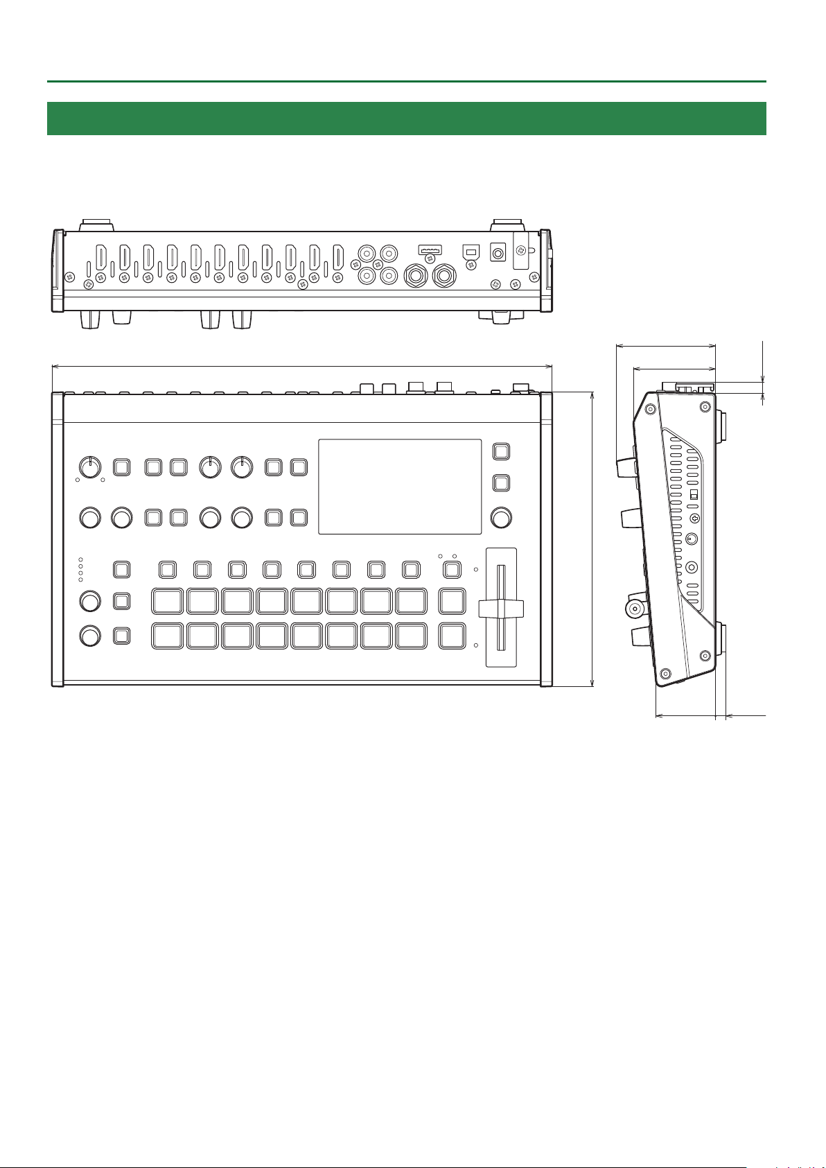
Appendix
Dimensions
317
63
52
Unit: mm
7
187
38 7
72
Page 73

MIDI Implementation
Appendix
Model: V-8HD
Date: January 28. 2020
Version: 1.03
Symbol I tem Setting Range
n MIDI Channel Fixed at 00H
1. MIDI Messages Received at MIDI IN
9Channel Voice Messages
7Control Change
6 Panpot (Controller Number 10)
This control the position of video fader.
Status 2nd Byte 3rd Byte
BnH 0AH vvH
vv = 00H–7FH (00H: bottom edge, 7FH: top edge)
6 Expression (Controller Number 11)
This control the value of TRANSITION TYPE.
Status 2nd Byte 3rd Byte
BnH 0BH vvH
vv = 00H–03H (MIX, WIPE)
6 Eect Control 1 (Controller Number 12)
This control the value of MIX/WIPE TIME.
Status 2nd Byte 3rd Byte
BnH 0CH vvH
vv = 00H–28H (0.0–4.0sec)
6 Eect Control 2 (Controller Number 13)
This control the value of PinP 1 TIME.
Status 2nd Byte 3rd Byte
BnH 0DH vvH
vv = 00H–28H (0.0–4.0sec)
6 Undened (Controller Number 14)
This control the value of PinP 2 TIME.
Status 2nd Byte 3rd Byte
BnH 0EH vvH
vv = 00H–28H (0.0–4.0sec)
6 Undened (Controller Number 15)
This control the value of DSK TIME.
Status 2nd Byte 3rd Byte
BnH 0FH vvH
vv = 00H–28H (0.0–4.0sec)
6 General Purpose Controllers 1 (Controller Number 16)
This control the value of PinP 1 SOURCE.
Status 2nd Byte 3rd Byte
BnH 10H vvH
vv = 00H–0FH (HDMI 1–8, STILL 1–8)
6 General Purpose Controllers 2 (Controller Number 17)
This control the value of PinP 1 POSITION H.
Status 2nd Byte 3rd Byte
BnH 11H vvH
vv = 0AH–64H (-50–50%)
6 General Purpose Controllers 3 (Controller Number 18)
This control the value of PinP 1 POSITION V.
Status 2nd Byte 3rd Byte
BnH 12H vvH
vv = 0AH–64H (-50–50%)
6 General Purpose Controllers 4 (Controller Number 19)
This control the value of PinP 1 SIZE.
Status 2nd Byte 3rd Byte
BnH 13H vvH
vv = 0AH–64H (10–100%)
6 Undened (Controller Number 20)
This control the value of PinP 1 VIEW ZOOM.
Status 2nd Byte 3rd Byte
BnH 14H vvH
vv = 0AH–64H (100–1000%)
6 Undened (Controller Number 21)
This control the value of PinP 2 SOURCE.
Status 2nd Byte 3rd Byte
BnH 15H vvH
vv = 00H–0FH (HDMI 1–8, STILL 1–8)
6 Undened (Controller Number 22)
This control the value of PinP 2 POSITION H.
Status 2nd Byte 3rd Byte
BnH 16H vvH
vv = 0AH–64H (-50–50%)
6 Undened (Controller Number 23)
This control the value of PinP 2 POSITION V.
Status 2nd Byte 3rd Byte
BnH 17H vvH
vv = 0AH–64H (-50–50%)
6 Undened (Controller Number 24)
This control the value of PinP 2 SIZE.
Status 2nd Byte 3rd Byte
BnH 18H vvH
vv = 0AH–64H (10–100%)
6 Undened (Controller Number 25)
This control the value of PinP 2 VIEW ZOOM.
Status 2nd Byte 3rd Byte
BnH 19H vvH
vv = 0AH–64H (100–1000%)
6 Undened (Controller Number 26)
This control the value of DSK SOURCE.
Status 2nd Byte 3rd Byte
BnH 1AH vvH
vv = 00H–0FH (HDMI 1–8, STILL 1–8)
6 Undened (Controller Number 27)
This control the value of DSK LEVEL.
Status 2nd Byte 3rd Byte
BnH 1BH vvH
vv = 00H–7FH (Converted to 0–255)
73
Page 74

Appendix
6 Undened (Controller Number 28)
This control the value of DSK GAIN.
Status 2nd Byte 3rd Byte
BnH 1CH vvH
vv = 00H–7FH (Converted to 0–255)
6 Undened (Controller Number 29)
This control the value of DSK MIX LEVEL.
Status 2nd Byte 3rd Byte
BnH 1DH vvH
vv = 00H–7FH (Converted to 0–255)
6 Undened (Controller Number 30)
This control the value of SPLIT/VFX A SW.
Status 2nd Byte 3rd Byte
BnH 1EH vvH
vv = 00H, 01H (OFF, ON)
6 Undened (Controller Number 31)
This control the value of SPLIT/VFX A TYPE.
Status 2nd Byte 3rd Byte
BnH 1FH vvH
vv = 00H–11H (refer to p. 79)
6 Bank select (Controller Number 32)
This control the value of SPLIT/VFX B SW.
Status 2nd Byte 3rd Byte
BnH 20H vvH
vv = 00H, 01H (OFF, ON)
6 Channel volume (Controller Number 39)
This control the value of AUDIO INPUT LEVEL (INPUT 4).
Status 2nd Byte 3rd Byte
BnH 27H vvH
vv = 00H–7FH
(refer to “Control Value–Input/Output Level Correspondence Table” (p. 75))
6 Balance (Controller Number 40)
This control the value of AUDIO INPUT LEVEL (INPUT 5).
Status 2nd Byte 3rd Byte
BnH 28H vvH
vv = 00H–7FH
(refer to “Control Value–Input/Output Level Correspondence Table” (p. 75))
6 Undened (Controller Number 41)
This control the value of AUDIO INPUT LEVEL (INPUT 6).
Status 2nd Byte 3rd Byte
BnH 29H vvH
vv = 00H–7FH
(refer to “Control Value–Input/Output Level Correspondence Table” (p. 75))
6 Panpot (Controller Number 42)
This control the value of AUDIO INPUT LEVEL (INPUT 7).
Status 2nd Byte 3rd Byte
BnH 2AH vvH
vv = 00H–7FH
(refer to “Control Value–Input/Output Level Correspondence Table” (p. 75))
6 Expression (Controller Number 43)
This control the value of AUDIO INPUT LEVEL (INPUT 8).
Status 2nd Byte 3rd Byte
BnH 2BH vvH
vv = 00H–7FH
(refer to “Control Value–Input/Output Level Correspondence Table” (p. 75))
6 Modulation (Controller Number 33)
This control the value of SPLIT/VFX B TYPE.
Status 2nd Byte 3rd Byte
BnH 21H vvH
vv = 00H–11H (refer to p. 79)
6 Bless Controller (Controller Number 34)
This control the [OUTPUT FADE] knob position (counter-clockwise)
Status 2nd Byte 3rd Byte
BnH 22H vvH
vv = 00H–3FH
6 Undened (Controller Number 35)
This control the [OUTPUT FADE] knob position (clockwise)
Status 2nd Byte 3rd Byte
BnH 23H vvH
vv = 00H–3FH
6 Foot Controller (Controller Number 36)
This control the value of AUDIO INPUT LEVEL (INPUT 1).
Status 2nd Byte 3rd Byte
BnH 24H vvH
vv = 00H–7FH
(refer to “Control Value–Input/Output Level Correspondence Table” (p. 75))
6 Portamento Time (Controller Number 37)
This control the value of AUDIO INPUT LEVEL (INPUT 2).
Status 2nd Byte 3rd Byte
BnH 25H vvH
vv = 00H–7FH
(refer to “Control Value–Input/Output Level Correspondence Table” (p. 75))
6 Eect Control 1 (Controller Number 44)
This control the value of AUDIO INPUT LEVEL (AUDIO IN).
Status 2nd Byte 3rd Byte
BnH 2CH vvH
vv = 00H–7FH
(refer to “Control Value–Input/Output Level Correspondence Table” (p. 75))
6 Eect Control 2 (Controller Number 45)
This control the value of AUDIO OUTPUT LEVEL.
Status 2nd Byte 3rd Byte
BnH 2DH vvH
vv = 00H–7FH
(refer to “Control Value–Input/Output Level Correspondence Table” (p. 75))
6 Undened (Controller Number 52)
Presses or release the [CUT] button.
Status 2nd Byte 3rd Byte
BnH 34H vvH
vv = 00H, 01H (OFF, ON)
6 Undened (Controller Number 53)
Presses release the [AUTO] button.
Status 2nd Byte 3rd Byte
BnH 35H vvH
vv = 00H, 01H (OFF, ON)
6 Undened (Controller Number 54)
Switches the video as “H CUT I.”
Status 2nd Byte 3rd Byte
BnH 36H vvH
vv = any (00H–7FH)
6 Data Entry (Controller Number 38)
This control the value of AUDIO INPUT LEVEL (INPUT 3).
Status 2nd Byte 3rd Byte
BnH 26H vvH
vv = 00H–7FH
(refer to “Control Value–Input/Output Level Correspondence Table” (p. 75))
74
6 Undened (Controller Number 55)
Switches the video as “H AUTO TAKE I.”
Status 2nd Byte 3rd Byte
BnH 37H vvH
vv = any (00H–7FH)
Page 75

Appendix
6 Undened (Controller Number 56)
This control the value of AUDIO INPUT MUTE (INPUT 1).
Status 2nd Byte 3rd Byte
BnH 38H vvH
vv = 00H, 01H (OFF, ON)
6 Undened (Controller Number 57)
This control the value of AUDIO INPUT MUTE (INPUT 2).
Status 2nd Byte 3rd Byte
BnH 39H vvH
vv = 00H, 02H (OFF, ON)
6 Undened (Controller Number 58)
This control the value of AUDIO INPUT MUTE (INPUT 3).
Status 2nd Byte 3rd Byte
BnH 3AH vvH
vv = 00H, 03H (OFF, ON)
6 Undened (Controller Number 59)
This control the value of AUDIO INPUT MUTE (INPUT 4).
Status 2nd Byte 3rd Byte
BnH 3BH vvH
vv = 00H, 04H (OFF, ON)
6 Undened (Controller Number 60)
This control the value of AUDIO INPUT MUTE (INPUT 5).
Status 2nd Byte 3rd Byte
BnH 3CH vvH
vv = 00H, 05H (OFF, ON)
6 Undened (Controller Number 61)
This control the value of AUDIO INPUT MUTE (INPUT 6).
Status 2nd Byte 3rd Byte
BnH 3DH vvH
vv = 00H, 06H (OFF, ON)
6 Undened (Controller Number 62)
This control the value of AUDIO INPUT MUTE (INPUT 7).
Status 2nd Byte 3rd Byte
BnH 3EH vvH
vv = 00H, 07H (OFF, ON)
9 Control Value–Input/Output Level Correspondence Table (unit: dB)
0 -Inf 32 -33.1 64 -11.3 96 -0.3
1 -80.0 33 -32.3 65 -10.7 97 0.0
2 -76.7 34 -31.5 66 -10.3 98 0.3
3 -73.3 35 -30.8 67 -10.0 99 0.7
4 -70.0 36 -30.0 68 -9.7 100 1.0
5 -66.7 37 -29.3 69 -9.3 101 1.3
6 -63.3 38 -28.7 70 -9.0 102 1.7
7 -60.0 39 -28.0 71 -8.7 103 2.0
8 -58.6 40 -27.3 72 -8.3 104 2.3
9 -57.1 41 -26.7 73 -8.0 105 2.7
10 -55.7 42 -26.0 74 -7.7 106 3.0
11 -54.3 43 -25.3 75 -7.3 107 3.3
12 -52.9 44 -24.7 76 -7.0 108 3.7
13 -51.4 45 -24.0 77 -6.7 109 4.0
14 -50.0 46 -23.3 78 -6.3 110 4.3
15 -48.9 47 -22.7 79 -6.0 111 4.7
16 -47.8 48 -22.0 80 -5.7 112 5.0
17 -46.7 49 -21.3 81 -5.3 113 5.3
18 -45.6 50 -20.7 82 -5.0 114 5.7
19 -44.4 51 -20.0 83 -4.7 115 6.0
20 -43.3 52 -19.3 84 -4.3 116 6.3
21 -42.2 53 -18.7 85 -4.0 117 6.7
22 -41.1 54 -18.0 86 -3.7 118 7.0
23 -40.0 55 -17.3 87 -3.3 119 7.3
24 -39.2 56 -16.7 88 -3.0 120 7.7
25 -38.5 57 -16.0 89 -2.7 121 8.0
26 -37.7 58 -15.3 90 -2.3 122 8.3
27 -36.9 59 -14.7 91 -2.0 123 8.7
28 -36.2 60 -14.0 92 -1.7 124 9.0
29 -35.4 61 -13.3 93 -1.3 125 9.3
30 -34.6 62 -12.7 94 -1.0 126 9.7
31 -33.8 63 -12.0 95 -0.7 127 10.0
7Program Change
This message recalls a preset memory.
Status 2nd Byte
CnH ppH
pp = Memory number: 00H–07H (MEMORY 1–MEMORY 8)
6 Undened (Controller Number 63)
This control the value of AUDIO INPUT MUTE (INPUT 8).
Status 2nd Byte 3rd Byte
BnH 3FH vvH
vv = 00H, 08H (OFF, ON)
6 Hold 1 (Controller Number 64)
This control the value of AUDIO INPUT MUTE (AUDIO IN).
Status 2nd Byte 3rd Byte
BnH 40H vvH
vv = 00H, 09H (OFF, ON)
6 Portamento Switch (Controller Number 65)
This control the value of AUDIO OUTPUT MUTE.
Status 2nd Byte 3rd Byte
BnH 41H vvH
vv = 00H, 10H (OFF, ON)
75
Page 76

Appendix
9System Exclusive Messages
Status Data Byte Status
F0H iiH,ddH,...,eeH F7H
F0H: Status of system exclusive message
ii= ID number: This is the ID to recognize manufacturer of the exclusive
message (manufacturer ID).
The manufacturer ID of Roland is 41H.
The ID numbers of 7EH and 7FH are expansion of MIDI standards
and used as universal non-realtime message (7EH) of universal
realtime message (7FH).
dd,...,ee= data: 00H–7FH (0–127)
F7H: EOX (end of exclusive)
7Data Request 1 (RQ1)
This is the message to request of “send data” to the connected device. Specify data
type and amount using address and size. When this is received, the unit sends the
requested data as “Data Set 1 (DT1)” message in case the unit is in status where the
sending of data is possible and requested address and size are appropriate. If not, the
unit sends nothing.
Status Data Byte Status
F0H 41H, 10H, 00H, 00H, 00H, 54H, 11H, aaH, F7H
bbH, ccH, ssH, ttH, uuH, sum
Byte Explanation
F0H Exclusive Status
41H Manufacturer ID (Roland)
10H Device ID
00H 1st byte of model ID (V-8HD)
00H 2nd byte of model ID (V-8HD)
00H 3rd byte of model ID (V-8HD)
68H 4th byte of model ID (V-8HD)
11H Command ID (RQ1)
aaH Address upper byte
bbH Address middle byte
ccH Address lower byte
ssH Size upper byte
ttH Size middle byte
uuH Size lower byte
sum Checksum
F7H EOX (end of exclusive)
7Data Set 1 (DT1)
This is the message of actual data transmission. Use this when you want to set data
to the unit.
Status Data Byte Status
F0H 41H, 10H, 00H, 00H, 00H, 54H, 12H, aaH, F7H
bbH, ccH, ddH, ..., eeH, sum
Byte Explanation
F0H Exclusive Status
41H Manufacturer ID (Roland)
10H Device ID
00H 1st byte of model ID (V-8HD)
00H 2nd byte of model ID (V-8HD)
00H 3rd byte of model ID (V-8HD)
68H 4th byte of model ID (V-8HD)
12H Command ID (DT1)
aaH Address upper byte
bbH Address middle byte
ccH Address lower byte
ddH Data: actual data to transmit. Multiple byte data is sent in address order.
: :
eeH Data
sum Checksum
F7H EOX (end of exclusive)
* Depending on the data type, the amount of single-time transmission is specied.
It is necessary to execute data request according to the specied rst address and
size. Refer to the “2. Parameter Address Map” (p. 77) for address and size.
* See “Example of an Exclusive Message and Calculating a Checksum” (p. 87) for
checksum.
* Data exceeding 256 bytes should be divided into packets of 256 bytes or smaller. If
you send data set 1 successively, set interval of 20 ms or longer between packets.
* Depending on the data type, the amount of single-time transmission is specied.
It is necessary to execute data request according to the specied rst address and
size. Refer to the “2. Parameter Address Map” (p. 77) for address and size.
* See “Example of an Exclusive Message and Calculating a Checksum” (p. 87) for
checksum.
76
Page 77

2. Parameter Address Map
Start Address Description
00H 00H 00H Video Parameter Area
01H 00H 00H Audio Parameter Area
02H 00H 00H System Parameter Area
0AH 00H 00H Other Parameter Area
10H 00H 00H Video Parameter (Memory 1)
11H 00H 00H Audio Parameter (Memory 1)
14H 00H 00H Video Parameter (Memory 2)
15H 00H 00H Audio Parameter (Memory 2)
18H 00H 00H Video Parameter (Memory 3)
19H 00H 00H Audio Parameter (Memory 3)
1CH 00H 00H Video Parameter (Memory 4)
1DH 00H 00H Audio Parameter (Memory 4)
20H 00H 00H Video Parameter (Memory 5)
21H 00H 00H Audio Parameter (Memory 5)
24H 00H 00H Video Parameter (Memory 6)
25H 00H 00H Audio Parameter (Memory 6)
28H 00H 00H Video Parameter (Memory 7)
29H 00H 00H Audio Parameter (Memory 7)
2CH 00H 00H Video Parameter (Memory 8)
2DH 00H 00H Audio Parameter (Memory 8)
Appendix
7Video Parameter Area
6 Video Input
* “xxH” corresponds to the respective channels as indicated below.
xxH: 00H–05H (CH1–CH6)
Address Parameter Name Sys.Ex.Value Meaning of Value
00H xxH 00H INPUT ASSIGN 00H–08H HDMI, STILL 1–8
00H xxH 01H FLIP H 00H–01H OFF, ON
00H xxH 02H FLIP V 00H–01H OFF, ON
00H xxH 03H BRIGHTNESS 60H–00H–1FH -32–0–31
00H xxH 04H CONTRAST 60H–00H–1FH -32–0–31
00H xxH 05H SATURATION 60H–00H–1FH -32–0–31
6 Vodeo Input (SCALER)
* “xxH” corresponds to the respective channels as indicated below.
xxH: 06H–05H (CH7–CH8)
Address Parameter Name Sys.Ex.Value Meaning of Value
00H xxH 00H INPUT ASSIGN 00H–08H HDMI, STILL 1–8
00H xxH 01H FLICKER FILTER 00H–01H OFF, ON
00H xxH 02H FLIP H 00H–01H OFF, ON
00H xxH 03H FLIP V 00H–01H OFF, ON
00H xxH 04H EDID 00H–0BH
00H xxH 05H
00H xxH 07H SCALING TYPE 00H–04H FULL, LET TERBOX, CROP, DOT BY DOT, MANUAL
00H xxH 08H
00H xxH 0AH
00H xxH 0CH
00H xxH 0EH
00H xxH 10H BRIGHTNESS 60H–00H–1FH -32–0–31
00H xxH 11H CONTRAST 60H–00H–1FH -32–0–31
00H xxH 12H SATURATION 60H–00H–1FH -32–0–31
00H xxH 13H RED 40H–00H–3FH -64–0–63
00H xxH 14H GREEN 40H–00H–3FH -64–0–63
00H xxH 15H BLUE 40H–00H–3FH -64–0–63
ZOOM 00H 64H–4EH 10H 10.0–1000.0%
06H
MANUAL SIZE H 70H 30H–00H –0FH 50H -2000–0–2000
09H
MANUAL SIZE V 70H 30H–00H–0FH 50H -2000–0–2000
0BH
POSITION H 71H 00H–00H–0FH 00H -1920–0–1920
0DH
POSITION V 76H 50H–00H–09H 30H -1200–0–1200
0FH
INTERNAL, SVGA(800x600), XGA(1024x768), WXGA(1280x800),
FWXGA(1366x768), SXGA(1280x1024), SXGA+(1400x1050),
UXGA(1600x1200), WUXGA(1920x1200), 720p, 1080i, 1080p
77
Page 78

Appendix
6 Video Output
* “xxH” corresponds to the respective channels as indicated below.
xxH: 08H–0AH (OUTPUT 1–3)
Address Parameter Name Sys.Ex.Value Meaning of Value
00H xxH 00H OUTPUT ASSIGN 00H–03H PROGRAM, PREVIEW, AUX, MULTI VIEW
00H xxH 01H COLOR SPACE 00H–02H YPbPr, RGB (0–255), RGB (16–235)
00H xxH 02H DVI-D/HDMI SIGNAL 00H–01H HDMI, DVI-D
00H xxH 03H BRIGHTNESS 40H–00H–3FH -64–0–63
00H xxH 04H CONTRAST 40H–00H–3FH -64–0–63
00H xxH 05H SATURATION 40H–00H–3FH -64–0–63
00H xxH 06H RED 40H–00H–3FH -64–0–63
00H xxH 07H GREEN 40H–00H–3FH -64–0–63
00H xxH 08H BLUE 40H–00H–3FH -64–0–63
00H xxH 09H REC CONTROL 00H–01H OFF, ON
6 TRANSITION TIME
Address Parameter Name Sys.Ex.Value Meaning of Value
00H 0BH 00H MIX/WIPE TIME 00H–28H 0.0–4.0sec
00H 0BH 01H PinP 1 TIME 00H–28H 0.0–4.0sec
00H 0BH 02H PinP 2 TIME 00H–28H 0.0–4.0sec
00H 0BH 03H DSK TIME 00H–28H 0.0–4.0sec
6 MIX/WIPE
Address Parameter Name Sys.Ex.Value Meaning of Value
00H 0CH 00H TRANS TYPE 00H–01H MIX, WIPE
00H 0CH 01H MIX TYPE 00H–02H MIX, FAM, NAM
00H 0CH 02H WIPE TYPE 00H–07H
00H 0CH 03H WIPE DIRECTION 00H–02H NORMAL, REVERSE, ROUND TRIP
00H 0CH 04H WIPE BORDER COLOR 00H–08H WHITE, YELLOW, CYAN, GREEN, MAGENTA, RED, BLUE, BLACK, SOFT EDGE
00H 0CH 05H WIPE BORDER WIDTH 00H–0EH 0–14
HORIZONTAL, VERTICAL, UPPER LEFT, UPPER RIGHT, LOWER LEFT,
LOWER RIGHT, H-CENTER, V-CENTER
6 PinP
* “xxH” corresponds to the respective channels as indicated below.
xxH: 0DH–0EH (PinP 1, 2)
Address Parameter Name Sys.Ex.Value Meaning of Value
00H xxH 00H PGM SW 00H–01H OFF, ON
00H xxH 01H PVW SW 00H–01H OFF, ON
00H xxH 02H SOURCE 00H–0FH HDMI1–8, STILL1–8
00H xxH 03H TYPE 00H–03H PinP, LUMINANCE-WHITE KEY, LUMINANCE-BLACK KEY, CHROMA KEY
00H xxH 04H
00H xxH 06H
00H xxH 08H
00H xxH 0AH
00H xxH 0CH
00H xxH 0EH SHAPE 00H–02H RECTANGLE, CIRCLE, DIAMOND
00H xxH 0FH BORDER COLOR 00H–08H WHITE, YELLOW, CYAN, GREEN, MAGENTA, RED, BLUE, BLACK, SOFT EDGE
00H xxH 10H BORDER WIDTH 00H–0EH 0–14
00H xxH 11H
00H xxH 13H
00H xxH 15H
00H xxH 17H
00H xxH 19H
00H xxH 1BH
00H xxH 1DH CHROMA COLOR 00H–01H GREEN, BLUE
00H xxH 1EH HUE WIDTH 62H–00H–1EH -30–0–30
POSITION H 7CH 0CH–00H 00H–03H 74H -50.0–0.0–50.0%
05H
POSITION V 7CH 0CH–00H 00H–03H 74H -50.0–0.0–50.0%
07H
SIZE 00H 64H–07H 68H 10.0–100.0%
09H
CROPPING H 00H 00H–07H 68H 0.0–100.0%
0BH
CROPPING V 00H 00H–07H 68H 0.0–100.0%
0DH
VIEW POSITION H 00H 64H–07H 68H 10.0–100.0%
12H
VIEW POSITION V 00H 64H–07H 68H 10.0–100.0%
14H
VIEW ZOOM 00H 64H–03H 10H 100–400%
16H
KEY LEVEL 00H 00H–01H 7FH 0–255
18H
KEY GAIN 00H 00H–01H 7FH 0–255
1AH
MIX LEVEL 00H 00H–01H 7FH 0–255
1CH
78
Page 79

Address Parameter Name Sys.Ex.Value Meaning of Value
00H xxH 1FH
00H xxH 21H
00H xxH 23H
00H xxH 25H FILL TYPE 00H–01H BUS, MATTE
00H xxH 26H MATTE COLOR 00H–07H WHITE, YELLOW, CYAN, GREEN, MAGENTA, RED, BLUE, BLACK
00H xxH 27H EDGE TYPE 00H–04H OFF, BORDER, DROP, SHADOW, OUTLINE
00H xxH 28H EDGE COLOR 00H–07H WHITE, YELLOW, CYAN, GREEN, MAGENTA, RED, BLUE, BLACK
00H xxH 29H EDGE WIDTH 00H–0EH 0–14
HUE FINE 00H 00H–02H 68H 0–360
20H
SATURATION WIDTH 7FH 00H–00H 00H–00H 7FH -128–0–127
22H
SATURATION FINE 00H 00H–01H 7FH 0–255
24H
6 DSK
Address Parameter Name Sys.Ex.Value Meaning of Value
00H 0FH 00H PGM SW 00H–01H OFF, ON
00H 0FH 01H PVW SW 00H–01H OFF, ON
00H 0FH 02H SOURCE 00H–0FH HDMI 1–8, STILL 1–8
00H 0FH 03H TYPE 00H–02H LUMINANCE-WHITE, LUMINANCE-BLACK, CHROMA
00H 0FH 04H
00H 0FH 06H
00H 0FH 08H
00H 0FH 0AH CHROMA COLOR 00H–01H GREEN, BLUE
00H 0FH 0BH HUE WIDTH 62H–00H–1EH -30–0–30
00H 0FH 0CH
00H 0FH 0EH
00H 0FH 10H
00H 0FH 12H FILL TYPE 00H–01H BUS, MATTE
00H 0FH 13H MATTE COLOR 00H–07H WHITE, YELLOW, CYAN, GREEN, MAGENTA, RED, BLUE, BLACK
00H 0FH 14H EDGE TYPE 00H–04H OFF, BORDER, DROP, SHADOW, OUTLINE
00H 0FH 15H EDGE COLOR 00H–07H WHITE, YELLOW, CYAN, GREEN, MAGENTA, RED, BLUE, BLACK
00H 0FH 16H EDGE WIDTH 00H–0EH 0–14
DSK LEVEL 00H 00H–01H 7FH 0–255
05H
DSK GAIN 00H 00H–01H 7FH 0–255
07H
MIX LEVEL 00H 00H–01H 7FH 0–255
09H
HUE FINE 00H 00H–02H 68H 0–360
0DH
SATURATION WIDTH 7FH 00H–00H 00H–00H 7FH -128–0–127
0FH
SATURATION FINE 00H 00H–01H 7FH 0–255
11H
Appendix
6 SPLIT/VFX
* “xxH” corresponds to the respective channels as indicated below.
xxH: 10H–11H (SPLIT/VFX A, B)
Address Parameter Name Sys.Ex.Value Meaning of Value
00H xxH 00H SPLIT/VFX SW 00H–01H OFF, ON
SPLIT_V, SPLIT_H, PART MOSAIC, BACKGROUND MOSAIC, FULL MOSAIC,
00H xxH 01H SPLIT/VFX TYPE 00H–11H
00H xxH 02H
00H xxH 04H PART MOSAIC MODE 00H–07H OFF (1x1), 4 x 4, 8 x 8, 16 x 16, 32 x 32, 64 x 64, 128 x 128, 256 x 256
00H xxH 05H
00H xxH 07H
00H xxH 09H
00H xxH 0BH
00H xxH 0DH
00H xxH 0FH BG MOSAIC MODE 00H–07H OFF (1x1), 4 x 4, 8 x 8, 16 x 16, 32 x 32, 64 x 64, 128 x 128, 256 x 256
00H xxH 10H
00H xxH 12H
MIX LEVEL 00H 00H–01H 7FH 0–255
03H
PART MOSAIC POSITION H 7CH 0CH–00H 00H–03H 74H -50.0–0.0–50.0%
06H
PART MOSAIC POSITION V 7CH 0CH–00H 00H–03H 74H -50.0–0.0–50.0%
08H
PART MOSAIC AREA SIZE 00H 64H–07H 68H 10.0–100.0%
0AH
PART MOSAIC AREA CORRECTION H 00H 64H–07H 68H 10.0–100.0%
0CH
PART MOSAIC AREA CORRECTION V 00H 64H–07H 68H 10.0–100.0%
0EH
BG MOSAIC POSITION H 7CH 0CH–00H 00H–03H 74H -50.0–0.0–50.0%
11H
BG MOSAIC POSITION V 7CH 0CH–00H 00H–03H 74H -50.0–0.0–50.0%
13H
WAVE, RGB REPLACE, COLOR PASS, NEGATIVE, COLORIZE, POSTERIZE,
SILHOUETTE, EMBOSS, FIND EDGES, MONOCOLOR, HUE OFFSET,
SATURATION OFFSET, VALUE OFFSET
79
Page 80

Appendix
Address Parameter Name Sys.Ex.Value Meaning of Value
00H xxH 14H
00H xxH 16H
00H xxH 18H
00H xxH 1AH FULL MOSAIC MODE 00H–07H OFF (1x1), 4 x 4, 8 x 8, 16 x 16, 32 x 32, 64 x 64, 128 x 128, 256 x 256
00H xxH 1BH
00H xxH 1DH WAVE TYPE 00H–07H 0–7
00H xxH 1EH RGB REPLACE TYPE 00H–05H OFF (R.G.B), B.R.G, G.B.R, R.B.G, G.R.B, B.G.R
00H xxH 1FH COLOR PASS TYPE 01H–3FH 1–63
00H xxH 20H NEGATIVE TYPE 01H–07H Pr, Pb, PbPr, Y, YPr, YPb, YPbPr
00H xxH 21H COLORIZE TYPE 00H–07H 1–8
00H xxH 22H POSTERIZE LEVEL 00H–03H 1–4
00H xxH 23H SILHOUETTE TYPE 00H–7FH 1–128
00H xxH 24H EMBOSS TYPE 00H–7FH 1–128
00H xxH 25H EMBOSS CONTRAST 00H–0FH 0–15
00H xxH 26H FIND EDGES FG COLOR 00H–0FH 0–15
00H xxH 27H FIND EDGES BG COLOR 00H–0FH 0–15
00H xxH 28H MONOCOLOR Pb COLOR 00H–3FH 0–63
00H xxH 29H MONOCOLOR Pr COLOR 00H–3FH 0–63
00H xxH 2AH
00H xxH 2CH
00H xxH 2EH
00H xxH 30H
00H xxH 32H
00H xxH 34H
00H xxH 36H SPLIT BORDER COLOR 00H–07H WHITE, YELLOW, CYAN, GREEN, MAGENTA, RED, BLUE, BLACK
00H xxH 37H SPLIT BORDER WIDTH 00H–0EH 0–14
BG MOSAIC AREA SIZE 00H 64H–07H 68H 10.0–100.0%
15H
BG MOSAIC AREA CORRECTION H 00H 64H–07H 68H 10.0–100.0%
17H
BG MOSAIC AREA CORRECTION V 00H 64H–07H 68H 10.0–100.0%
19H
WAVE GAIN 00H 00H–01H 7FH 0–255
1CH
HUE OFFSET VALUE 00H 00H–02H 67H 0–359
2BH
SATURATION OFFSET VALUE 7EH 00H–00H 00H– 01H 7FH -256–0–255
2DH
VALUE OFFSET VALUE 7EH 00H–00H 00H–01H 7FH -256–0–255
2FH
SPLIT CENTER A 7CH 0CH–00H 00H–03H 74H -50.0–0.0–50.0%
31H
SPLIT CENTER B 7CH 0CH–00H 00H–03H 74H -50.0–0.0–50.0%
33H
SPLIT CENTER POSITION 7CH 0CH–00H 00H–03H 74H -50.0–0.0–50.0%
35H
6 Panel
Address Parameter Name Sys.Ex.Value Meaning of Value
00H 12H 00H PGM Select 00H–07H INPUT1–8
00H 12H 01H PST Select 00H–07H INPUT1–8
00H 12H 02H AUX Select 00H–07H INPUT1–8
00H 12H 03H
00H 12H 05H AB Bus Select 00H–01H A, B
AB Fader Level 00H 00H–0FH 7FH 0–2047
04H
80
Page 81

7Audio Parameter Area
6 Audio Input
* “xxH” corresponds to the respective channels as indicated below.
xxH: 00H–08H (INPUT 1–8, AUDIO IN)
Address Parameter Name Sys.Ex.Value Meaning of Value
01H xxH 00H
01H
INPUT LEVEL
02H
01H xxH 03H INPUT MUTE 00H–01H OFF, ON
01H xxH 04H SOLO 00H–01H OFF, ON
01H xxH 05H EFFECT PRESET 00H–06H
01H xxH 06H
01H xxH 08H HIGH PASS FILTER 75Hz 00H–01H OFF, ON
01H xxH 09H NOISE GATE SW 00H–01H OFF, ON
01H xxH 0AH
01H xxH 0CH NOISE GATE RELEASE 00H–7FH 30–5000ms
01H xxH 0DH COMPRESSOR SW 00H–01H OFF, ON
01H xxH 0EH
01H xxH 10H COMPRESSOR RATIO 00H–0DH
01H xxH 11H COMPRESSOR ATTACK 00H–19H 0.2–100ms
01H xxH 12H COMPRESSOR RELEASE 00H–7FH 30–5000ms
01H xxH 13H COMPRESSOR AUTO GAIN 00H–01H OFF, ON
01H xxH 14H
01H xxH 16H EQUALIZER SW 00H–01H OFF, ON
01H xxH 17H
01H xxH 19H EQUALIZER Hi FREQUENCY 44H–78H 1.00–20.0kHz
01H xxH 1AH
01H xxH 1CH EQUALIZER Mid FREQUENCY 00H–78H 20Hz–20.0kHz
01H xxH 1DH EQUALIZER Mid Q 00H–05H 0.5–16.0
01H xxH 1EH
01H xxH 20H EQUALIZER Lo FREQUENCY 00H–38H 20–500Hz
DELAY 00H 00H–27H 08H 0.0–500.0ms
07H
NOISE GATE THRESHOLD 79H 60H–00H 00H -80.0–0.0dB
0BH
COMPRESSOR THRESHOLD 7BH 28H–00H 00H -60.0–0.0dB
0FH
COMPRESSOR MAKEUP GAIN 7CH 70H–00H 00H–03H 10H -40.0–0.0–40.0dB
15H
EQUALIZER Hi GAIN 7EH 6AH–00H 00H–01H 16H -15.0–0.0–15.0dB
18H
EQUALIZER Mid GAIN 7EH 6AH–00H 00H–01H 16H -15.0–0.0–15.0dB
1BH
EQUALIZER Lo GAIN 7EH 6AH–00H 00H–01H 16H -15.0–0.0–15.0dB
1FH
7EH 00H 00H,
7FH 79H 60H–00H 00H 00H– 00H 00H 64H
-INFdB,
-80.0–0.0–10.0dB
DEFAULT, MEETING, INTERVIEW, AMBIENT MIC, WINDY FIELD,
DE-ESS/POPS SOFT, DE-ESS/POPS HARD
1.00:1, 1.12:1, 1.25:1, 1.40:1, 1.60:1, 1.80:1, 2.00:1, 2.50:1, 3.20:1,
4.00:1, 5.60:1, 8.00:1, 16.0:1, INF:1
Appendix
6 Audio Output Assign
Address Parameter Name Sys.Ex.Value Meaning of Value
01H 10H 00H AUDIO OUT 00H–01H MASTER OUTPUT, AUX
01H 10H 01H PHONES OUT 00H–01H MASTER OUTPUT, AUX
6 Audio Master Output
Address Parameter Name Sys.Ex.Value Meaning of Value
01H 11H 00H
01H
02H
01H 11H 03H OUTPUT MUTE 00H–01H OFF, ON
01H 11H 04H LIMITER SW 00H–01H OFF, ON
01H 11H 05H
01H 11H 07H EQUALIZER SW 00H–01H OFF, ON
01H 11H 08H
01H 11H 0AH EQUALIZER Hi FREQUENCY 44H–78H 1.00–20.0kHz
01H 11H 0BH
01H 11H 0DH EQUALIZER Mid FREQUENCY 00H–78H 20Hz–20.0kHz
01H 11H 0EH EQUALIZER Mid Q 00H–05H 0.5–16.0
01H 11H 0FH
OUTPUT LEVEL
LIMITER THRESHOLD 7CH 70H–00H 00H -40.0–0.0dB
06H
EQUALIZER Hi GAIN 7EH 6AH–00H 00H–01H 16H -15.0–0.0–15.0dB
09H
EQUALIZER Mid GAIN 7EH 6AH–00H 00H–01H 16H -15.0–0.0–15.0dB
0CH
EQUALIZER Lo GAIN 7EH 6AH–00H 00H–01H 16H -15.0–0.0–15.0dB
10H
7EH 00H 00H,
7FH 79H 60H–00H 00H 00H–00H 00H 64H
-INFdB,
-80.0–0.0–10.0dB
81
Page 82
Appendix
Address Parameter Name Sys.Ex.Value Meaning of Value
01H 11H 11H EQUALIZER Lo FREQUENCY 00H–38H 20–500Hz
01H 11H 12H MULTI BAND COMPRESSOR SW 00H–01H OFF, ON
01H 11H 13H
01H 11H 15H MB COMP Hi RATIO 00H–0DH
01H 11H 16H
01H 11H 18H MB COMP Mid RATIO 00H–0DH
01H 11H 19H
01H 11H 1BH MB COMP Lo RATIO 00H–0DH
6 Audio AUX Output
Address Parameter Name Sys.Ex.Value Meaning of Value
01H 11H 00H
01H 11H 03H OUTPUT MUTE 00H–01H OFF, ON
01H 11H 04H LIMITER SW 00H–01H OFF, ON
01H 11H 05H
01H 11H 07H AUX SEND VIDEO 00H–01H OFF, ON
01H 11H 08H AUX SEND AUDIO IN 00H–01H OFF, ON
01H 11H 09H AUX EFFECT INPUT 1 00H–01H DRY, WET
01H 11H 0AH AUX EFFECT INPUT 2 00H–01H DRY, WET
01H 11H 0BH AUX EFFECT INPUT 3 00H–01H DRY, WET
01H 11H 0CH AUX EFFECT INPUT 4 00H–01H DRY, WET
01H 11H 0DH AUX EFFECT INPUT 5 00H–01H DRY, WET
01H 11H 0EH AUX EFFECT INPUT 6 00H–01H DRY, WET
01H 11H 0FH AUX EFFECT INPUT 7 00H–01H DRY, WET
01H 11H 10H AUX EFFECT INPUT 8 00H–01H DRY, WET
01H 11H 11H AUX EFFECT AUDIO IN 00H–01H DRY, WET
MB COMP Hi THRESHOLD 7CH 70H–00H 00H -40.0–0.0dB
14H
MB COMP Mid THRESHOLD 7CH 70H–00H 00H -40.0–0.0dB
17H
MB COMP Lo THRESHOLD 7CH 70H–00H 00H -40.0–0.0dB
1AH
01H
OUTPUT LEVEL
02H
LIMITER THRESHOLD 7CH 70H–00H 00H -40.0–0.0dB
06H
7EH 00H 00H,
7FH 79H 60H–00H 00H 00H–00H 00H 64H
1.00:1, 1.12:1, 1.25:1, 1.40:1, 1.60:1, 1.80:1, 2.00:1, 2.50:1, 3.20:1,
4.00:1, 5.60:1, 8.00:1, 16.0:1, INF:1
1.00:1, 1.12:1, 1.25:1, 1.40:1, 1.60:1, 1.80:1, 2.00:1, 2.50:1, 3.20:1,
4.00:1, 5.60:1, 8.00:1, 16.0:1, INF:1
1.00:1, 1.12:1, 1.25:1, 1.40:1, 1.60:1, 1.80:1, 2.00:1, 2.50:1, 3.20:1,
4.00:1, 5.60:1, 8.00:1, 16.0:1, INF:1
-INFdB,
-80.0–0.0–10.0dB
6 Audio Follow
Address Parameter Name Sys.Ex.Value Meaning of Value
01H 20H 00H INPUT 1 00H–01H OFF, ON
01H 20H 01H INPUT 2 00H–01H OFF, ON
01H 20H 02H INPUT 3 00H–01H OFF, ON
01H 20H 03H INPUT 4 00H–01H OFF, ON
01H 20H 04H INPUT 5 00H–01H OFF, ON
01H 20H 05H INPUT 6 00H–01H OFF, ON
01H 20H 06H INPUT 7 00H–01H OFF, ON
01H 20H 07H INPUT 8 00H–01H OFF, ON
01H 20H 08H AUDIO IN 00H–08H OFF, INPUT 1–8
82
Page 83
Appendix
7System Parameter Area
6 Version
Address Parameter Name Sys.Ex.Value Meaning of Value
02H 00H 00H System Version Major 00H–09H Version Number (Read Only)
02H 00H 01H System Version Minor (1) 00H–09H Version Number (Read Only)
02H 00H 02H System Version Minor (2) 00H–09H Version Number (Read Only)
6 System
Address Parameter Name Sys.Ex.Value Meaning of Value
02H 01H 00H HDCP 00H–01H OFF, ON
02H 01H 01H FRAME RATE 00H–01H 59.94, 50Hz
02H 01H 02H SYSTEM FORMAT 00H–02H 720p, 1080i, 1080p
02H 01H 03H CUT SW ASSIGN 00H–04H
02H 01H 04H AUTO SW ASSIGN 00H–04H
02H 01H 05H PANEL OPERATION 00H–01H A/B, PGM/PST
02H 01H 06H AUX LINKED PGM 00H–02H OFF, AUTO, MANUAL
02H 01H 07H OUTPUT FADE LEFT ASSIGN 00H–0CH
02H 01H 08H OUTPUT FADE RIGHT ASSIGN 00H–0CH
02H 01H 09H USER 1 SW ASSIGN 00H–23H
02H 01H 0AH USER 2 SW ASSIGN 00H–23H
02H 01H 0BH LED DIMMER 01H–08H 1–8
02H 01H 0CH LCD DIMMER 01H–08H 1–8
02H 01H 0DH ON SCREEN MENU 00H–03H UPPER LEFT, UPPER RIGHT, LOWER LEFT, LOWER RIGHT
02H 01H 0EH TALLY FRAME 00H–01H OFF, ON
02H 01H 0FH AUX/PinP MARK 00H–01H OFF, ON
02H 01H 10H AUDIO LEVEL METER SW 00H–01H OFF, ON
02H 01H 11H AUDIO LEVEL METER AUDIO IN 00H–02H OFF, LOWER, UPPER
02H 01H 12H MULTI-VIEW LABEL 00H–01H OFF, ON
02H 01H 13H MULTI-VIEW LAYOUT 00H–03H PVW.PGM, PGM.PVW, BLACK.PGM, PGM.BLACK
02H 01H 14H OUTPUT 3 OSD ON SCREEN MENU 00H–01H OFF, ON
02H 01H 15H OUTPUT 3 OSD TALLY FRAME 00H–01H OFF, ON
02H 01H 16H OUTPUT 3 OSD LABEL/LEVEL METER/MARK 00H–01H OFF, ON
02H 01H 17H AUTO INPUT DETECT 00H–01H OFF, ON
02H 01H 18H AUTO OFF 00H–01H OFF, ON
02H 01H 19H TEST PATTERN 00H–05H OFF, 75% COLOR BAR, 100% COLOR BAR, RAMP, STEP, HATCH
02H 01H 1AH TEST TONE 00H–03H OFF, -20dB@1kHz, -10dB@1kHz, 0dB@1kHz
HAUTO TAKE,
AUTO TAKEI,
BLACK, WHITE, AUDIO, BLACK&AUDIO, WHITE&AUDIO, STILL 1–8
OUTPUT
BLACK, WHITE, AUDIO, BLACK&AUDIO, WHITE&AUDIO, STILL 1–8
OUTPUT
N/A, FREEZE, AUTO SWITCHING, BPM TAP, INPUT 1–8 ASSIGN,
STILL 1–8 OUTPUT, INPUT 1–8 MUTE, AUDIO IN MUTE,
OUTPUT MUTE, AUX MUTE, INPUT SCAN N, INPUT SCAN R,
MEMORY SCAN N, MEMORY SCAN R, REC START/STOP
N/A, FREEZE, AUTO SWITCHING, BPM TAP, INPUT 1–8 ASSIGN,
STILL 1–8 OUTPUT, INPUT 1–8 MUTE, AUDIO IN MUTE,
OUTPUT MUTE, AUX MUTE, INPUT SCAN N, INPUT SCAN R,
MEMORY SCAN N, MEMORY SCAN R, REC START/STOP
HAUTO TAKEI, HCUT, HCUTI, HTRANSFORM
HAUTO TAKEI, CUTI, HCUTI, TRANSFORMI
6 Panel Lock
Address Parameter Name Sys.Ex.Value Meaning of Value
02H 02H 00H A/PGM 1 SW 00H–01H OFF, ON
02H 02H 01H A/PGM 2 SW 00H–01H OFF, ON
02H 02H 02H A/PGM 3 SW 00H–01H OFF, ON
02H 02H 03H A/PGM 4 SW 00H–01H OFF, ON
02H 02H 04H A/PGM 5 SW 00H–01H OFF, ON
02H 02H 05H A/PGM 6 SW 00H–01H OFF, ON
02H 02H 06H A/PGM 7 SW 00H–01H OFF, ON
02H 02H 07H A/PGM 8 SW 00H–01H OFF, ON
02H 02H 08H B/PST 1 SW 00H–01H OFF, ON
02H 02H 09H B/PST 2 SW 00H–01H OFF, ON
02H 02H 0AH B/PST 3 SW 00H–01H OFF, ON
02H 02H 0BH B/PST 4 SW 00H–01H OFF, ON
02H 02H 0CH B/PST 5 SW 00H–01H OFF, ON
02H 02H 0DH B/PST 6 SW 00H–01H OFF, ON
02H 02H 0EH B/PST 7 SW 00H–01H OFF, ON
02H 02H 0FH B/PST 8 SW 00H–01H OFF, ON
83
Page 84

Appendix
Address Parameter Name Sys.Ex.Value Meaning of Value
02H 02H 10H CUT SW 00H–01H OFF, ON
02H 02H 11H AUTO SW 00H–01H OFF, ON
02H 02H 12H AUX SW 00H–01H OFF, ON
02H 02H 13H MODE SW 00H–01H OFF, ON
02H 02H 14H TRANSITION SW 00H–01H OFF, ON
02H 02H 15H VIDEO FADER 00H–01H OFF, ON
02H 02H 16H VFX/SPLIT A BLOCK 00H–01H OFF, ON
02H 02H 17H VFX/SPLIT B BLOCK 00H–01H OFF, ON
02H 02H 18H PinP 1 BLOCK 00H–01H OFF, ON
02H 02H 19H PinP 2 BLOCK 00H–01H OFF, ON
02H 02H 1AH DSK BLOCK 00H–01H OFF, ON
02H 02H 1BH USER 1 SW 00H–01H OFF, ON
02H 02H 1CH USER 2 SW 00H–01H OFF, ON
02H 02H 1DH CAPTURE IMAGE SW 00H–01H OFF, ON
02H 02H 1EH OUTPUT FADE 00H–01H OFF, ON
6 Preset Memory
Address Parameter Name Sys.Ex.Value Meaning of Value
02H 03H 00H START UP 00H–08H LAST MEMORY, MEMORY 1–8
02H 03H 01H MEMORY PROTECT 00H–01H OFF, ON
02H 03H 02H PinP FADE TIME 00H–0AH 0.0–1.0s
02H 03H 03H LOAD PARAMETER / VIDEO INPUT 00H–01H OFF, ON
02H 03H 04H LOAD PARAMETER / VIDEO OUTPUT 00H–01H OFF, ON
02H 03H 05H LOAD PARAMETER / TRANSITION TIME 00H–01H OFF, ON
02H 03H 06H LOAD PARAMETER / MIX/WIPE 00H–01H OFF, ON
02H 03H 07H LOAD PARAMETER / PinP 00H–01H OFF, ON
02H 03H 08H LOAD PARAMETER / DSK 00H–01H OFF, ON
02H 03H 09H LOAD PARAMETER / VFX/SPLIT 00H–01H OFF, ON
02H 03H 0AH LOAD PARAMETER / AUDIO INPUT 00H–01H OFF, ON
02H 03H 0BH LOAD PARAMETER / AUDIO OUTPUT 00H–01H OFF, ON
02H 03H 0CH LOAD PARAMETER / AUDIO FOLLOW 00H–01H OFF, ON
6 FREEZE
Address Parameter Name Sys.Ex.Value Meaning of Value
02H 04H 00H FREEZE TYPE 00H–01H ALL, SELEC T
02H 04H 01H FREEZE_SELECT INPUT 1 00H–01H DISABLE, ENABLE
02H 04H 02H FREEZE_SELECT INPUT 2 00H–01H DISABLE, ENABLE
02H 04H 03H FREEZE_SELECT INPUT 3 00H–01H DISABLE, ENABLE
02H 04H 04H FREEZE_SELECT INPUT 4 00H–01H DISABLE, ENABLE
02H 04H 05H FREEZE_SELECT INPUT 5 00H–01H DISABLE, ENABLE
02H 04H 06H FREEZE_SELECT INPUT 6 00H–01H DISABLE, ENABLE
02H 04H 07H FREEZE_SELECT INPUT 7 00H–01H DISABLE, ENABLE
02H 04H 08H FREEZE_SELECT INPUT 8 00H–01H DISABLE, ENABLE
84
Page 85
6 AUTO SWITCHING
Address Parameter Name Sys.Ex.Value Meaning of Value
02H 05H 00H AUTO SWITCHING SW 00H–01H OFF, ON
02H 05H 01H AUTO SWITCHING TYPE 00H–02H INPUT SCAN, PRESET MEMORY SCAN, BPM SYNC
02H 05H 02H INPUT SCAN SEQUENCE 00H–02H NORMAL, REVERSE, RANDOM
02H 05H 03H INPUT SCAN TRANSITION TIME 00H–28H 0.0–4.0s
02H 05H 04H INPUT SCAN TIME / INPUT 1 00H–78H 0 –120s
02H 05H 05H INPUT SCAN TIME / INPUT 2 00H–78H 0–120s
02H 05H 06H INPUT SCAN TIME / INPUT 3 00H–78H 0–120s
02H 05H 07H INPUT SCAN TIME / INPUT 4 00H–78H 0–120s
02H 05H 08H INPUT SCAN TIME / INPUT 5 00H–78H 0–120s
02H 05H 09H INPUT SCAN TIME / INPUT 6 00H–78H 0–120s
02H 05H 0AH INPUT SCAN TIME / INPUT 7 00H–78H 0–120s
02H 05H 0BH INPUT SCAN TIME / INPUT 8 00H–78H 0 –120s
02H 05H 0CH MEMORY SCAN SEQUENCE 00H–02H NORMAL, REVERSE, RANDOM
02H 05H 0DH MEMORY SCAN TIME / MEMORY 1 00H–78H 0–120s
02H 05H 0EH MEMORY SCAN TIME / MEMORY 2 00H–78H 0–120s
02H 05H 0FH MEMORY SCAN TIME / MEMORY 3 00H–78H 0–120s
02H 05H 10H MEMORY SCAN TIME / MEMORY 4 00H–78H 0–120s
02H 05H 11H MEMORY SCAN TIME / MEMORY 5 00H–78H 0–120s
02H 05H 12H MEMORY SCAN TIME / MEMORY 6 00H–78H 0–120s
02H 05H 13H MEMORY SCAN TIME / MEMORY 7 00H–78H 0–120s
02H 05H 14H MEMORY SCAN TIME / MEMORY 8 00H–78H 0–120s
02H 05H 15H
02H 05H 17H BPM SYNC MODE 00H–01H TRANSITION, CUT
02H 05H 18H BPM SYNC SPEED 00H–03H x1/4, x1/2, x1, x2
BPM SYNC BPM 00H 14H–01H 7AH 20–250
16H
Appendix
6 CTL/EXP
* “xxH” corresponds to the respective channels as indicated below.
xxH: 06H–07H (CTL/EXP 1, 2)
Address Parameter Name Sys.Ex.Value Meaning of Value
02H xxH 00H CTL/EXP TYPE 00H–02H OFF, CTL A & CTL B, EXP
02H xxH 01H
02H xxH 03H
02H xxH 05H EXP ASSIGN 00H–19H refer to p. 64
CTL A ASSIGN 00H 00H–01H 0AH
02H
CTL B ASSIGN 00H 00H–01H 0AH
04H
refer to p. 63
6 LABEL EDIT
* “xxH” corresponds to the respective channels as indicated below.
xxH: 10H–1FH (HDMI 1–8, STILL 1–8)
Address Parameter Name Sys.Ex.Value Meaning of Value
02H xxH 00H LABEL (0) 20H–7EH Character shown in the label (1st character)
02H xxH 01H LABEL (1) 20H–7EH Character shown in the label (2nd character)
02H xxH 02H LABEL (2) 20H–7EH Character shown in the label (3rd character)
02H xxH 03H LABEL (3) 20H–7EH Character shown in the label (4th character)
02H xxH 04H LABEL (4) 20H–7EH Character shown in the label (5th character)
02H xxH 05H LABEL (5) 20H–7EH Character shown in the label (6th character)
02H xxH 06H LABEL (6) 20H–7EH Character shown in the label (7th character)
02H xxH 07H LABEL (7) 20H–7EH Character shown in the label (8th character)
85
Page 86

Appendix
7Other Parameter Area
6 Memory
Address Parameter Name Sys.Ex.Value Meaning of Value
0AH 00H 00H Memory Load Trigger 00H–07H Memory 1–8 (Write Only)
0AH 00H 01H Memory Save Trigger 00H–07H Memory 1–8 (Write Only)
0AH 00H 02H Memory Initialize Trigger 00H–07H Memory 1–8 ( Write Only)
0AH 00H 03H Loaded Memory Number 00H–07H, 7FH Memory 1–8, Last Memory (Read Only)
7Preset Memory Area
You can load or rewrite the stored contents of the preset memories.
* The 2nd byte and 3rd byte of a Preset Memory Area address, and the value range, are in common with the Video Parameter Area (00H 00H 00H) and the Audio Parameter
Area (01H 00H 00H).
Address Parameter Name Meaning of Value
10H xxH xxH Video Parameter (Memory 1) Load/rewrite video parameter stored in Memory 1
11H xxH xxH Audio Parameter (Memory 1) Load/rewrite audio parameter stored in Memory 1
14H xxH xxH Video Parameter (Memory 2) Load/rewrite video parameter stored in Memory 2
15H xxH xxH Audio Parameter (Memory 2) Load/rewrite audio parameter stored in Memory 2
18H xxH xxH Video Parameter (Memory 3) Load/rewrite video parameter stored in Memory 3
19H xxH xxH Audio Parameter (Memory 3) Load/rewrite audio parameter stored in Memory 3
1CH xxH xxH Video Parameter (Memory 4) Load/rewrite video parameter stored in Memory 4
1DH xxH xxH Audio Parameter (Memory 4) Load/rewrite audio parameter stored in Memory 4
20H xxH xxH Video Parameter (Memory 5) Load/rewrite video parameter stored in Memory 5
21H xxH xxH Audio Parameter (Memory 5) Load/rewrite audio parameter stored in Memory 5
24H xxH xxH Video Parameter (Memory 6) Load/rewrite video parameter stored in Memory 6
25H xxH xxH Audio Parameter (Memory 6) Load/rewrite audio parameter stored in Memory 6
28H xxH xxH Video Parameter (Memory 7) Load/rewrite video parameter stored in Memory 7
29H xxH xxH Audio Parameter (Memory 7) Load/rewrite audio parameter stored in Memory 7
2CH xxH xxH Video Parameter (Memory 8) Load/rewrite video parameter stored in Memory 8
2DH xxH xxH Audio Parameter (Memory 8) Load/rewrite audio parameter stored in Memory 8
86
Page 87
Appendix
3. Supplementary Material
7Decimal and Hexadecimal Table
(Hexadecimal Numbers are Indicated by ‘H’)
In MIDI documentation, data values and addresses/sizes of exclusive messages etc.
are expressed as hexadecimal values for each 7 bits.
The following table shows how these correspond to decimal numbers.
D H D H D H D H
0 00H 32 20H 64 40H 96 60H
1 01H 33 21H 65 41H 97 61H
2 02H 34 22H 66 42H 98 62H
3 03H 35 23H 67 43H 99 63H
4 04H 36 24H 68 44H 100 64H
5 05H 37 25H 69 45H 101 65H
6 06H 38 26H 70 46H 102 66H
7 07H 39 27H 71 47H 103 67H
8 08H 40 28H 72 48H 104 68H
9 09H 41 29H 73 49H 105 69H
10 0AH 42 2AH 74 4AH 106 6AH
11 0BH 43 2BH 75 4BH 107 6BH
12 0CH 44 2CH 76 4CH 108 6CH
13 0DH 45 2DH 77 4DH 109 6DH
14 0EH 46 2EH 78 4EH 110 6EH
15 0FH 47 2FH 79 4FH 111 6FH
16 10H 48 30H 80 50H 112 70H
17 11H 49 31H 81 51H 113 71H
18 12H 50 32H 82 52H 114 72H
19 13H 51 33H 83 53H 115 73H
20 14H 52 34H 84 54H 116 74H
21 15H 53 35H 85 55H 117 75H
22 16H 54 36H 86 56H 118 76H
23 17H 55 37H 87 57H 119 77H
24 18H 56 38H 88 58H 120 78H
25 19H 57 39H 89 59H 121 79H
26 1AH 58 3AH 90 5AH 122 7AH
27 1BH 59 3BH 91 5BH 123 7BH
28 1CH 60 3CH 92 5CH 124 7CH
29 1DH 61 3DH 93 5DH 125 7DH
30 1EH 62 3EH 94 5EH 126 7EH
31 1FH 63 3FH 95 5FH 127 7FH
D: decimal
H: hexadecimal
* Decimal expressions used for MIDI channel, bank select, and program change are 1
greater than the decimal value shown in the above table.
* Hexadecimal values in 7-bit units can express a maximum of 128 levels in one byte
of data. If the data requires greater resolution, two or more bytes are used. For
example, a value indicated by a hexadecimal expression in two 7-bit bytes aa bbH
would be aa x 128 + bb.
* Data marked “nibbled” is expressed in hexadecimal in 4-bit units. A value expressed
as a 2-byte nibble 0a 0bH has the value of a x 16 + b.
<Example 1>
What is the decimal expression of 5AH?
From the preceding table, 5AH = 90
<Example 2>
What is the decimal expression of the value 12 34H given as hexadecimal for each 7
bits?
From the preceding table, since 12H = 18 and 34H = 52
18 x 128 + 52 = 2356
<Example 3>
What is the decimal expression of the nibbled value 0A 03 09 0D?
From the preceding table, since 0AH = 10, 03H = 3, 09H = 9, 0DH = 13
((10 x 16 + 3) x 16 + 9) x 16 + 13 = 41885
<Example 4>
What is the nibbled expression of the decimal value 1258?
16) 1258
16) 78... 10
16) 4... 14
0... 4
Since from the preceding table, 0 = 00H, 4 = 04H, 14 = 0EH, 10 = 0AH, the answer is
00 04 0E 0AH.
7MIDI Message Examples
<Example 1> 92H 3EH 5FH
9n is a note on status and n is the MIDI channel number.
As 2H = 2, 3EH = 62 and 5FH = 95, this is a note on message of MIDI CH =3 , note
number 62 (D4) and velocity 95.
<Example 2> CEH 49H
CnH is program change status, and n is the MIDI channel number.
As EH = 14 and 49H = 73, this is a program change message of MIDI CH = 15 and
program number 74 (in the GS sound map, Flute).
7Example of an Exclusive Message and Calculating a Checksum
Roland Exclusive messages are transmitted with a checksum at the end (before F7)
to make sure that the message was correctly received. The value of the checksum is
determined by the address and data (or size) of the transmitted exclusive message.
6 How to Calculate the Checksum
(Hexadecimal Numbers are Indicated by ‘H’)
The checksum is a value that produces a lower 7 bits of zero when the address, size,
and checksum itself are summed. If the exclusive message to be transmitted has an
address of aa bb ccH and the data is dd ee H, the actual calculation would be as
follows:
aa + bb + cc + dd + ee + = sum
sum / 128 = quotient ... remainder
128 - remainder = checksum
(However, the checksum will be 0 if the remainder is 0.)
<Example>
Setting Dissolve Time Ctrl Assign in MIDI Visual Control to Modulation for Control
Changes
From the “Parameter Address Map,” the start address of the Dissolve Time Ctrl Assign
in MIDI Visual Control is 10H 10H 02H and the Modulation parameter in Control
Change is 00H 01H. Therefore ...
F0H 7EH 00H 0CH 01H 10H 10H 02H 00H 01H ??H F7H
(1) (2) (3) (4) (5) (6) (7) (8)
(1) Exclusive Status
(2) ID Number (Universal SysEx Non Realtime)
(3) Device ID (0)
(4) Sub ID (MIDI Visual Control Version 1.0)
(5) Address
(6) Data
(7) Checksum
(8) EOX
Next calculate the checksum. Add (5) to (6).
10H + 10H + 02H + 00H + 01H = 16 + 16 + 2 + 0 + 1 = 35 (sum)
35 (sum) / 128 = 0 (quotient) ... 35 (remainder)
Checksum = 128 - 35 (remainder) = 93 = 5DH
Thus, the message to transmit is :
F0H 7EH 00H 0CH 01H 10H 10H 02H 00H 01H 5DH F7H
87
Page 88

HD Video Switcher
Model V-8HD
Function Transmitted Recognized Remarks
Basic
Channel
Mode
Note
Number
Velocity
After
Touch
Pitch Bend × ×
Default
Changed
Default
Messages
Altered
True Voice × ×
Note On
Note O
Key’s
Channel’s
MIDI Implementation Chart
0–9
10–31
32–46
46–51
52–65
66–119
1
1
×
×
**************
×
×
×
×
×
×
×
×
×
×
1
1
×
×
**************
×
×
×
×
×
O
O
×
O
×
Controls various parameters
Date: Jan. 28, 2020
Version: 1.03
Control
Change
Program
Change : True Number
System Exclusive O O
System
Common
System
Real Time
Aux
Messages
: Song Position
: Song Select
: Tune Request
: Clock
: Commands
: All Sound O
: Reset All Controllers
: Local On/O
: All Notes O
: Active Sensing
: System Reset
× O
×
×
×
×
×
×
×
×
×
×
×
1–8
×
×
×
×
×
×
×
×
×
×
×
Notes
Mode 1 : OMNI ON, POLY Mode 2 : OMNI ON, MONO
Mode 3 : OMNI OFF, POLY Mode 4 : OMNI OFF, MONO
88
O : Yes
X : No
Page 89
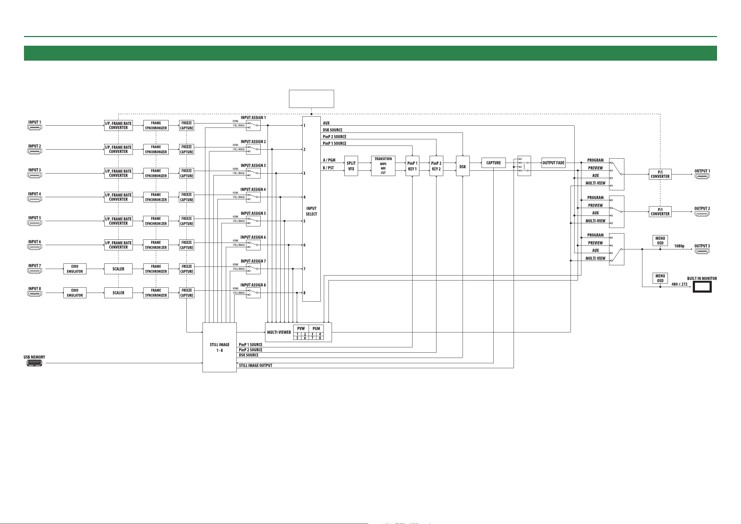
VIDEO Block Diagram
Appendix
CAPTURE
CAPTURE
SYSTEM FORMAT
1080p
1080i
720p
STILL IMAGE OUTPUT
OUTPUT ASSIGN
OUTPUT ASSIGN
OUTPUT ASSIGN
* Assign for “USER SW,” “CTL A/B,” or “OUTPUT FADE volume.”
89
Page 90

AUDIO Block Diagram
Appendix
CH 1 De-embedded
CH 2 De-embedded
L
R
INPUT BUS
MAIN
L R
INPUT
MUTE
AUX
EFFECT
WET
DRY
WET
DRY
AUDIO
FOLLOW
AUX
SEND
(HDMI AUDIO)
SOLO
INPUT
LEVEL
AUX
SW
* Same as video AUX selection
SOLO
L R
AUX
L R
AUX
MUTE
AUX
LEVEL
LIMITER
L R
LIMITER
INPUT
MUTE
AUDIO
FOLLOW
INPUT
LEVEL
OUTPUT BUS
MASTER
OUTPUT
L R L R
SOLO
L R
AUX
* Same as video output bus
CH 1 Embedded
CH 2 Embedded
CH 1 Embedded
CH 2 Embedded
CH 1 Embedded
CH 2 Embedded
OUTPUT 1
OUTPUT 2
OUTPUT 3
AUX
EFFECT
WET
DRY
WET
DRY
AUX
SEND
(AUDIO IN)
SOLO
PHONES LEVEL
L
R
L
R
90
 Loading...