

Page 1
Owner’s Manual (this document)
Read this rst. It explains the basic things you need to know in
order to use the V-60HD.
PDF Manual (download from the Web)
5 Reference Manual
This manual covers all menu items of the V-60HD.
It also describes control via RS-232, LAN, and TALLY/GPI.
Before using the V-60HD, ensure that its system program is at
the most recent version. For information on available upgrades for the
system program, see the Roland website (https://proav.roland.com/).
You can check the system program version by pressing the [MENU]
button0“SYSTEM”0“VERSION.”
To obtain the PDF manual
1. Enter the following URL in your computer.
https://proav.roland.com/
I
2. Go to the V-60HD product page and click the
“Support.”
Copyright © 2017 ROLAND CORPORATION
Page 2
Contents
USING THE UNIT SAFELY . . . . . . . . . . . . . . . . . . . . . . . . . . . . . . . . . . . . 3
IMPORTANT NOTES . . . . . . . . . . . . . . . . . . . . . . . . . . . . . . . . . . . . . . . . 5
Panel Descriptions . . . . . . . . . . . . . . . . . . . . . . . . . . . . . . . . . . . . . . . . . 6
Top Panel/Side Panel . . . . . . . . . . . . . . . . . . . . . . . . . . . . . . . . . . . . . 6
Rear Panel/Front Panel (Connecting Your Equipment) . . . . . . . . 8
Using Phantom Power . . . . . . . . . . . . . . . . . . . . . . . . . . . . . . . . 9
Multi-view Monitor Display . . . . . . . . . . . . . . . . . . . . . . . . . . . . . . . . 10
Basic Operations . . . . . . . . . . . . . . . . . . . . . . . . . . . . . . . . . . . . . . . . . . . 11
Turning the Power On and O . . . . . . . . . . . . . . . . . . . . . . . . . . . . . 11
Operating the Menu . . . . . . . . . . . . . . . . . . . . . . . . . . . . . . . . . . . . . . 11
Video Input/Output Settings . . . . . . . . . . . . . . . . . . . . . . . . . . . . . . . 12
Setting the Video Input/Output Format . . . . . . . . . . . . . . . . . . . . . 12
Setting the System Format . . . . . . . . . . . . . . . . . . . . . . . . . . . . 12
Setting the Input Formats for Channels 5 and 6 . . . . . . . . . . 12
Assigning a Video Source to Channel 6 . . . . . . . . . . . . . . . . . . . . . 13
Adjusting Output Video . . . . . . . . . . . . . . . . . . . . . . . . . . . . . . . . . . . 13
Adjusting the Input Video . . . . . . . . . . . . . . . . . . . . . . . . . . . . . . . . . 14
Changing Output Bus Assignments . . . . . . . . . . . . . . . . . . . . . . . . 15
Inputting Copyright-protected (HDCP) Video . . . . . . . . . . . . . . . . 15
Video Operations . . . . . . . . . . . . . . . . . . . . . . . . . . . . . . . . . . . . . . . . . . 16
Switching the Video . . . . . . . . . . . . . . . . . . . . . . . . . . . . . . . . . . . . . . 16
About the Operation Mode for Video Transitions . . . . . . . . . 16
Switching Using the PGM/PST Mode . . . . . . . . . . . . . . . . . . . . 16
Switching in the A/B Mode . . . . . . . . . . . . . . . . . . . . . . . . . . . . 17
Switching AUX Output . . . . . . . . . . . . . . . . . . . . . . . . . . . . . . . . 18
Using Imported Still Images . . . . . . . . . . . . . . . . . . . . . . . . . . . . . . . 18
Capturing a Still Image from Input Video . . . . . . . . . . . . . . . . 18
Importing a Still Image from a USB Flash Drive . . . . . . . . . . . 19
Assigning Still Images to Channels 7 and 8 . . . . . . . . . . . . . . 19
Deleting a Still Image . . . . . . . . . . . . . . . . . . . . . . . . . . . . . . . . . 19
Applying a Fade to PGM/PVW Output Video (Output Fade) . . . . 20
Audio Operations . . . . . . . . . . . . . . . . . . . . . . . . . . . . . . . . . . . . . . . . . . 24
Adjusting the Volume Level . . . . . . . . . . . . . . . . . . . . . . . . . . . . . . . 24
Adjusting the Head Amp Gain . . . . . . . . . . . . . . . . . . . . . . . . . 24
Adjusting the Sound Position (Pan) . . . . . . . . . . . . . . . . . . . . . 24
Adjusting the Volume Balance . . . . . . . . . . . . . . . . . . . . . . . . . 25
Outputting AUX-bus Audio . . . . . . . . . . . . . . . . . . . . . . . . . . . . . . . . 25
Applying Eects to Audio . . . . . . . . . . . . . . . . . . . . . . . . . . . . . . . . . 26
Applying Eects to Input Audio . . . . . . . . . . . . . . . . . . . . . . . . 26
Applying Eects to Output Audio . . . . . . . . . . . . . . . . . . . . . . 27
Controlling Volume Levels Automatically (Auto Mixing) . . . . . . . 28
Muting Out Specic Input Audio (Mute) . . . . . . . . . . . . . . . . . . . . 28
Interlinking Audio Output to Video Switching (Audio Follow) . . 29
Separating Discrete Analog Input Audio Streams and
Adding Them to SDI Video . . . . . . . 30
Other Features . . . . . . . . . . . . . . . . . . . . . . . . . . . . . . . . . . . . . . . . . . . . . 31
Saving/Recalling Settings (Preset Memory) . . . . . . . . . . . . . . . . . . 31
Saving the Unit’s Settings on a USB Flash Drive . . . . . . . . . . . . . . 32
Formatting USB Flash Drives . . . . . . . . . . . . . . . . . . . . . . . . . . . . . . . 33
Returning Settings to the Factory-default State
(Factory Reset) . . . . . . . . 33
Preventing Unintended Operation (Panel Lock) . . . . . . . . . . . . . . 34
Operating the V-60HD by Remote Control . . . . . . . . . . . . . . . . . . . 34
Outputting a Tally Signal . . . . . . . . . . . . . . . . . . . . . . . . . . . . . . . . . . 34
Appendices . . . . . . . . . . . . . . . . . . . . . . . . . . . . . . . . . . . . . . . . . . . . . . . . 35
Troubleshooting . . . . . . . . . . . . . . . . . . . . . . . . . . . . . . . . . . . . . . . . . 35
Block Diagram . . . . . . . . . . . . . . . . . . . . . . . . . . . . . . . . . . . . . . . . . . . 36
Video Section . . . . . . . . . . . . . . . . . . . . . . . . . . . . . . . . . . . . . . . . 36
Audio Section . . . . . . . . . . . . . . . . . . . . . . . . . . . . . . . . . . . . . . . . 38
Main Specications . . . . . . . . . . . . . . . . . . . . . . . . . . . . . . . . . . . . . . 40
Dimensions . . . . . . . . . . . . . . . . . . . . . . . . . . . . . . . . . . . . . . . . . . . . . 41
Transition Eects List . . . . . . . . . . . . . . . . . . . . . . . . . . . . . . . . . . . . . 42
Video Composition Operations . . . . . . . . . . . . . . . . . . . . . . . . . . . . . 21
Compositing Using Picture-in-Picture (PinP) . . . . . . . . . . . . . . . . . 21
Compositing Using Split . . . . . . . . . . . . . . . . . . . . . . . . . . . . . . . . . . 22
Compositing Using DSK. . . . . . . . . . . . . . . . . . . . . . . . . . . . . . . . . . . 23
Before using this unit, carefully read “USING THE UNIT SAFELY”
(p. 3) and “IMPORTANT NOTES” (p. 5). After reading, keep the
document(s) where it will be available for immediate reference.
Checking the Included Items
The V-60HD includes the following items. Please take a moment to conrm that all of these items have been included with the V-60HD.
If you nd that any item is missing, contact the nearest authorized Roland distributor in your country.
* The unit * AC Adaptor/Power cord * Owner’s Manual
* The shape of the power cord’s plug
varies depending on the country.
2
Page 3
USING THE UNIT SAFELY
About WARNING and CAUTION Notices
Used for instructions intended to alert the
user to the risk of death or severe injury
should the unit be used improperly.
Used for instructions intended to alert the
user to the risk of injury or material
damage should the unit be used
improperly.
* Material damage refers to damage or
other adverse eects caused with
respect to the home and all its
furnishings, as well to domestic animals
or pets.
ALWAYS OBSERVE THE FOLLOWING
WARNING
To completely turn o power to the unit, pull out
the plug from the outlet
Even with the power switch turned
o, this unit is not completely
separated from its main source of
power. When the power needs to
be completely turned o, turn o the power
switch on the unit, then pull out the plug
from the outlet. For this reason, the outlet
into which you choose to connect the power
cord’s plug should be one that is within easy
reach and readily accessible.
Concerning the Auto O function
The power to this unit will be
turned o automatically after a
predetermined amount of time
has passed since it was last used
for playing music, or its buttons or controls
were operated (Auto O function). If you
do not want the power to be turned o
automatically, disengage the Auto O
function (p. 11).
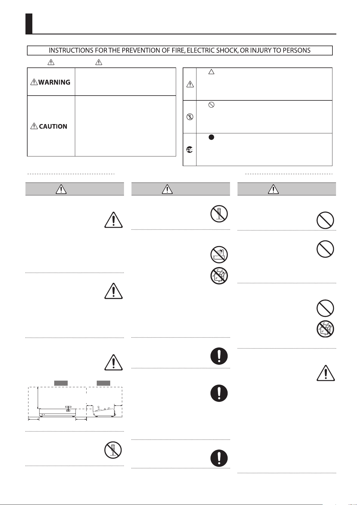
Secure a sucient amount of space at the setup
location
Since this unit normally emits a
slight amount of heat, make sure to
secure sucient space around it, as
shown below.
SideFront
30 cm (12 in.)
or greater
20 cm (8 in.)
or greater
5 cm (2 in.)
or greater
20 cm (8 in.)
or greater
15 cm (6 in.)
or greater
Do not disassemble or modify by yourself
Do not carry out anything unless
you are instructed to do so in the
owner’s manual. Otherwise, you
risk causing malfunction.
Do not repair or replace parts by yourself
Refer all servicing to your retailer,
the nearest Roland Service Center,
or an authorized Roland distributor,
as listed on the “Information.”
Do not use or store in the following types of
locations
• Subject to temperature extremes
(e.g., direct sunlight in an
enclosed vehicle, near a heating
duct, on top of heat-generating
equipment); or are
• Damp (e.g., baths, washrooms,
on wet oors); or are
• Exposed to steam or smoke; or are
• Subject to salt exposure; or are
• Exposed to rain; or are
• Dusty or sandy; or are
• Subject to high levels of vibration and
shakiness; or are
• Placed in a poorly ventilated location.
Do not place in an unstable location
Otherwise, you risk injury as the
result of the unit toppling over or
dropping down.
Use only the supplied AC adaptor and the correct
voltage
Be sure to use only the AC adaptor
supplied with the unit. Also,
make sure the line voltage at the
installation matches the input
voltage specied on the AC adaptor’s body.
Other AC adaptors may use a dierent
polarity, or be designed for a dierent
voltage, so their use could result in damage,
malfunction, or electric shock.
Use only the supplied power cord
Use only the attached power cord.
Also, the supplied power cord must
not be used with any other device.
About the Symbols
The symbol alerts the user to important instructions or
warnings.The specic meaning of the symbol is
determined by the design contained within the triangle. In
the case of the symbol at left, it is used for general
cautions, warnings, or alerts to danger.
The symbol alerts the user to items that must never be
carried out (are forbidden). The specic thing that must
not be done is indicated by the design contained within
the circle. In the case of the symbol at left, it means that
the unit must never be disassembled.
The symbol alerts the user to things that must be
carried out. The specic thing that must be done is
indicated by the design contained within the circle. In the
case of the symbol at left, it means that the power-cord
plug must be unplugged from the outlet.
WARNING
WARNING
Do not bend the power cord or place heavy objects
on it
Otherwise, re or electric shock
may result.
Avoid extended use at high volume
Use of the unit at high volume
for extended periods of time may
cause hearing loss. If you ever
experience any hearing loss or
ringing in the ears, you should immediately
stop using the unit and consult a specialized
physician.
Do not allow foreign objects or liquids to enter
unit; never place containers with liquid on unit
Do not place containers containing
liquid (e.g., ower vases) on this
product. Never allow foreign
objects (e.g., ammable objects,
coins, wires) or liquids (e.g., water
or juice) to enter this product.
Doing so may cause short circuits,
faulty operation, or other malfunctions.
Turn o the unit if an abnormality or malfunction
occurs
Immediately turn the unit o,
remove the AC adaptor from the
outlet, and request servicing by
your retailer, the nearest Roland
Service Center, or an authorized Roland
distributor, as listed on the “Information”
when:
• The AC adaptor or the power cord has
been damaged; or
• If smoke or unusual odor occurs; or
• Objects have fallen into, or liquid has been
spilled onto the unit; or
• The unit has been exposed to rain (or
otherwise has become wet); or
• The unit does not appear to operate
normally or exhibits a marked change in
performance.
3
Page 4
USING THE UNIT SAFELY
WARNING
Be cautious to protect children from injury
Always make sure that an adult is
on hand to provide supervision
and guidance when using the
unit in places where children are
present, or when a child will be using the
unit.
Do not drop or subject to strong impact
Otherwise, you risk causing
damage or malfunction.
Do not share an outlet with an unreasonable
number of other devices
Otherwise, you risk overheating
or re.
Do not use overseas
Before using the unit in overseas,
consult with your retailer, the
nearest Roland Service Center, or
an authorized Roland distributor, as
listed on the “Information.”
CAUTION
When disconnecting the power cord, grasp it by the
plug
To prevent conductor damage,
always grasp the power cord by its
plug when disconnecting it.
Periodically clean the power plug
An accumulation of dust or foreign
objects between the power plug
and the power outlet can lead to
re or electric shock.
At regular intervals, be sure to pull out the
power plug, and using a dry cloth, wipe away
any dust or foreign objects that may have
accumulated.
Disconnect the power plug whenever the unit will
not be used for an extended period of time
Fire may result in the unlikely event
that a breakdown occurs.
Route all power cords and cables in such a way as
to prevent them from getting entangled
Injury could result if someone were
to trip on a cable and cause the
unit to fall or topple.
Avoid climbing on top of the unit, or placing heavy
objects on it
Otherwise, you risk injury as the
result of the unit toppling over or
dropping down.
Never connect/disconnect a power plug if your
hands are wet
Otherwise, you could receive an
electric shock.
CAUTION
Precautions concerning use of phantom power
supply
Always turn the phantom power
o when connecting any device
other than condenser microphones
that require phantom power. You
risk causing damage if you mistakenly supply
phantom power to dynamic microphones,
audio playback devices, or other devices that
don’t require such power. Be sure to check
the specications of any microphone you
intend to use by referring to the manual that
came with it.
(This instrument’s phantom power:
48 V DC, 14 mA Max)
Disconnect all cords/cables before moving the unit
Before moving the unit, disconnect
the power plug from the outlet,
and pull out all cords from external
devices.
Before cleaning the unit, disconnect the power
plug from the outlet
If the power plug is not removed
from the outlet, you risk receiving
an electric shock.
Whenever there is a threat of lightning, disconnect
the power plug from the outlet
If the power plug is not removed
from the outlet, you risk causing
malfunction or receiving an electric
shock.
Handle the ground terminal carefully
If you remove the screw from the
ground terminal, be sure to replace
it; don’t leave it lying around where
it could accidentally be swallowed
by small children. When refastening the
screw, make that it is rmly fastened, so it
won’t come loose.
4
Page 5

IMPORTANT NOTES
Power Supply
• Do not connect this unit to same electrical
outlet that is being used by an electrical
appliance that is controlled by an
inverter or a motor (such as a refrigerator,
washing machine, microwave oven, or
air conditioner). Depending on the way
in which the electrical appliance is used,
power supply noise may cause this unit
to malfunction or may produce audible
noise. If it is not practical to use a separate
electrical outlet, connect a power supply
noise lter between this unit and the
electrical outlet.
• The AC adaptor will begin to generate
heat after long hours of consecutive
use. This is normal, and is not a cause for
concern.
Placement
• Using the unit near power ampliers
(or other equipment containing large
power transformers) may induce hum.
To alleviate the problem, change the
orientation of this unit; or move it farther
away from the source of interference.
• This unit may interfere with radio and
television reception. Do not use this unit in
the vicinity of such receivers.
• Noise may be produced if wireless
communications devices, such as cell
phones, are operated in the vicinity of
this unit. Such noise could occur when
receiving or initiating a call, or while
conversing. Should you experience such
problems, you should relocate such
wireless devices so they are at a greater
distance from this unit, or switch them o.
• When moved from one location to
another where the temperature and/or
humidity is very dierent, water droplets
(condensation) may form inside the unit.
Damage or malfunction may result if you
attempt to use the unit in this condition.
Therefore, before using the unit, you must
allow it to stand for several hours, until the
condensation has completely evaporated.
• Depending on the material and
temperature of the surface on which you
place the unit, its rubber feet may discolor
or mar the surface.
• Do not place containers or anything else
containing liquid on top of this unit. Also,
whenever any liquid has been spilled
on the surface of this unit, be sure to
promptly wipe it away using a soft, dry
cloth.
Maintenance
• Never use benzine, thinners, alcohol
or solvents of any kind, to avoid the
possibility of discoloration and/or
deformation.
Repairs and Data
• Before sending the unit away for repairs,
be sure to make a backup of the data
stored within it; or you may prefer to write
down the needed information. Although
we will do our utmost to preserve the data
stored in your unit when we carry out
repairs, in some cases, such as when the
memory section is physically damaged,
restoration of the stored content may be
impossible. Roland assumes no liability
concerning the restoration of any stored
content that has been lost.
Additional Precautions
• Any data stored within the unit can be
lost as the result of equipment failure,
incorrect operation, etc. To protect
yourself against the irretrievable loss
of data, try to make a habit of creating
regular backups of the data you’ve stored
in the unit.
• Roland assumes no liability concerning
the restoration of any stored content that
has been lost.
• Use a reasonable amount of care when
using the unit’s buttons, sliders, or other
controls; and when using its jacks and
connectors. Rough handling can lead to
malfunctions.
• Never strike or apply strong pressure to
the display.
• When disconnecting all cables, grasp the
connector itself—never pull on the cable.
This way you will avoid causing shorts, or
damage to the cable’s internal elements.
• To avoid disturbing others nearby, try
to keep the unit’s volume at reasonable
levels.
• This unit allows you to switch images at
high speed. For some people, viewing
such images can cause headache, nausea,
or other discomfort. Do not use this unit to
create video that might cause these types
of health problems. Roland Corporation
will accept no responsibility for any such
health problems that may occur in yourself
or in viewers.
• Do not use connection cables that contain
a built-in resistor.
Using External Memories
• Please observe the following precautions
when handling external memory devices.
Also, make sure to carefully observe all the
precautions that were supplied with the
external memory device.
• Do not remove the device while
reading/writing is in progress.
• To prevent damage from static
electricity, discharge all static electricity
from your person before handling the
device.
Intellectual Property Right
• It is forbidden by law to make an audio
recording, video recording, copy or
revision of a third party’s copyrighted work
(musical work, video work, broadcast, live
performance, or other work), whether
in whole or in part, and distribute, sell,
lease, perform or broadcast it without the
permission of the copyright owner.
• Do not use this product for purposes that
could infringe on a copyright held by a
third party. We assume no responsibility
whatsoever with regard to any
infringements of third-party copyrights
arising through your use of this product.
• This product can be used to record or
duplicate audio or visual material without
being limited by certain technological
copy-protection measures. This is due to
the fact that this product is intended to be
used for the purpose of producing original
music or video material, and is therefore
designed so that material that does not
infringe copyrights belonging to others
(for example, your own original works) can
be recorded or duplicated freely.
• This product contains eParts integrated
software platform of eSOL Co.,Ltd. eParts is
a trademark of eSOL Co., Ltd. in Japan.
• Roland is an either registered trademark
or trademark of Roland Corporation in the
United States and/or other countries.
• Company names and product names
appearing in this document are registered
trademarks or trademarks of their
respective owners.
• Fugue © 1999-2017 Kyoto Software
Research, Inc. All rights reserved.
5
Page 6
Panel Descriptions
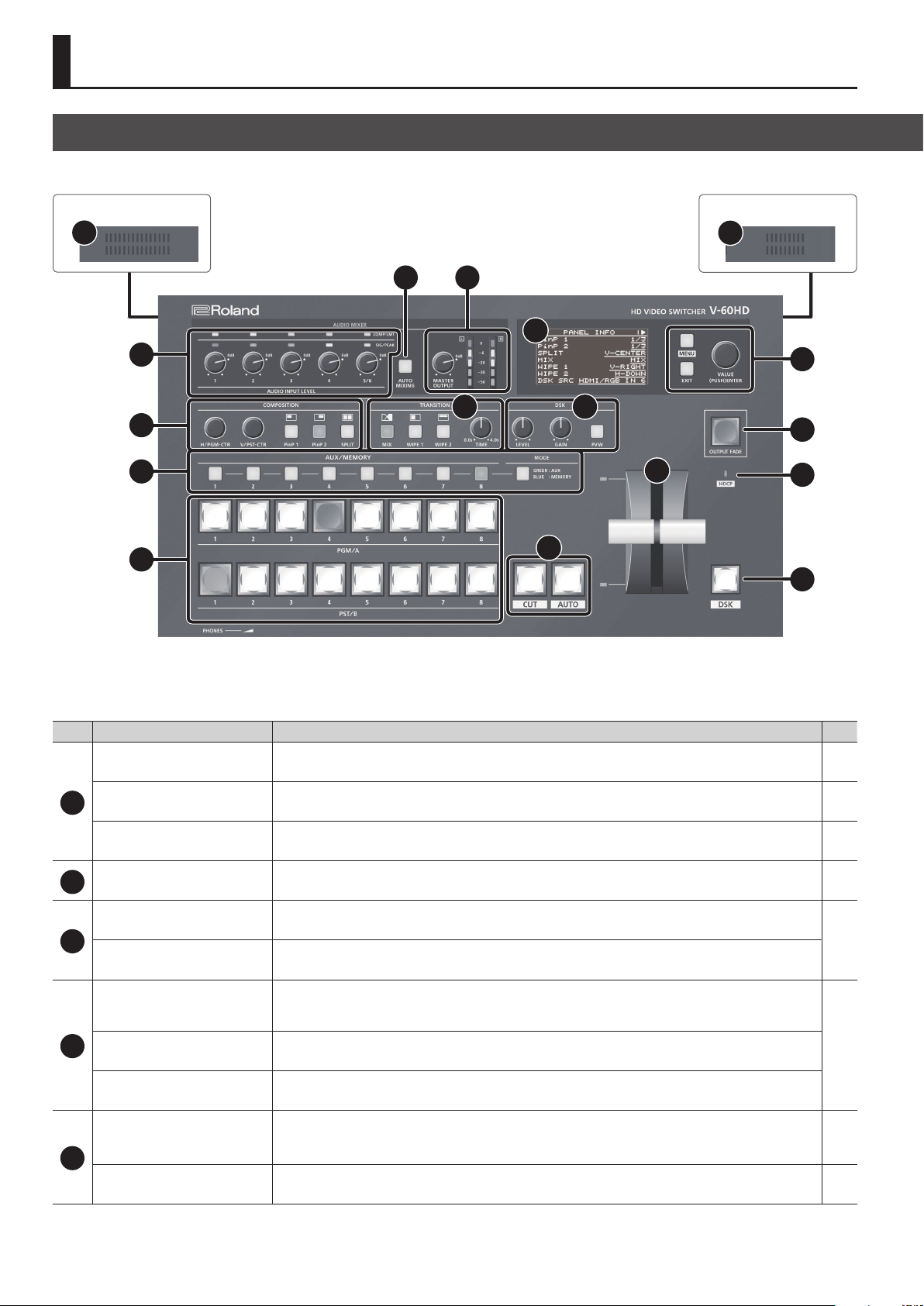
Top Panel/Side Panel
Side Panel
16
Side Panel
17
2 3
8
1
9
5 10
4
6
7
11
12
13
17
14
15
NO.
COMP/LMT indicators
AUDIO INPUT LEVEL
1
[1]–[5/6] knobs
SIG/PEAK indicators
[AUTO MIXING] button
2
[MASTER OUTPUT] knob
Name
3
MASTER OUTPUT level meter
[PinP 1] button
[PinP 2] button
[SPLIT] button
4
[H/PGM-CTR] knob
[V/PST-CTR] knob
[MIX] button
[WIPE 1] button
[WIPE 2] button
5
[TIME] knob
Explanation Page
When the compressor is turned on for AUDIO IN 1–5/6, this lights up when compression is applied. p. 26
These adjust the volume level for AUDIO IN 1–5/6. p. 25
This lights up when input via AUDIO IN 1–5/6 is detected, and when the volume level is too high.
This switches the Auto Mixing feature on and o. When the feature is turned on, the [AUTO MIXING]
button lights up.
This adjusts the volume level for master out.
This displays the volume level for master out.
This switches PinP or split video composition on and o. When the feature is turned on, the button lights
up.
PinP: This adjusts the horizontal display position of the inset screen.
Split: This adjusts the vertical and horizontal position of the video displayed above or on the left.
PinP: This adjusts the vertical display position of the inset screen.
Split: This adjusts the vertical and horizontal position of the video displayed below or on the right.
These select video transition eects. The selected button lights up.
This sets the video transition time. p. 17
p. 24
p. 28
p. 25
p. 21
p. 22
p. 16
p. 42
6
Page 7
Panel Descriptions
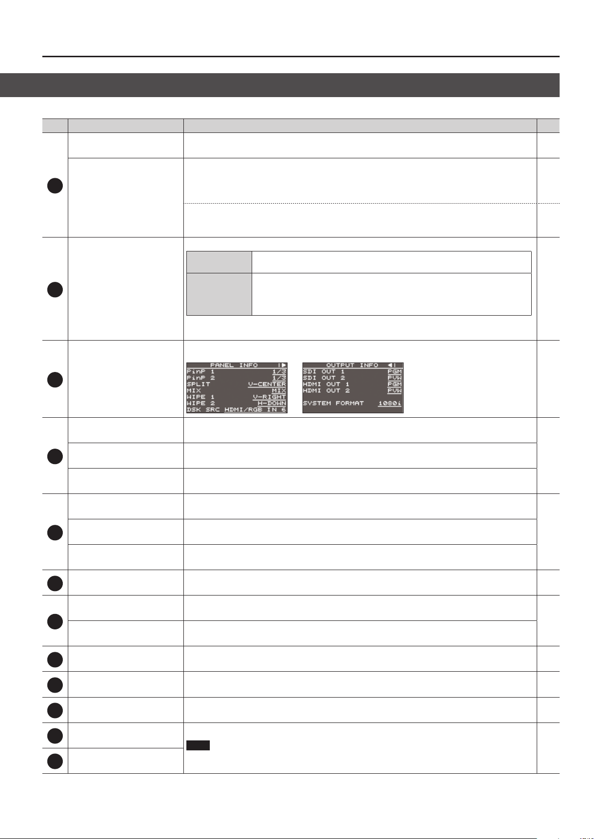
NO.
[MODE] button
Name
6
AUX/MEMORY [1]–[8] buttons
Cross-point [1]–[8] buttons
7
Built-in display
8
Explanation Page
This switches the functioning of the AUX/MEMORY buttons.
When the [MODE] button is lighted in green
The buttons function as AUX-bus selection buttons. They select the video (channel 1–8) to send to the
AUX bus. The selected button lights up in red.
The respective buttons also function as indicators showing the input status of the video.
When the [MODE] button is lighted in blue
The buttons function as preset-memory selection buttons. These save video and audio settings, the state
of the operation panel, and other current settings, and call up settings saved in memory.
These select the video to output.
PGM/A bus end
PST/B bus end
* The system functions as just described when the operation mode is set to “PGM/PST mode.” Operation
diers when in the A/B mode.
This displays current information about the V-60HD. There are the two types—PANEL INFO and OUTPUT
INFO—and you use the [VALUE] knob to switch between them.
These select the video (channel 1–8) to send to the PGM/A bus. The video on the
PGM/A bus becomes the nal video output. The selected button lights up in red.
These select the video (channel 1–8) to send to the PST/B bus. The video on the
PST/B bus is the preset video (the video to be output next). The selected button
lights up in green.
* While video compositing is in progress, the button lights up in red.
p. 18
p. 31
p. 18
p. 31
p. 16
—
[MENU] button
[EXIT] knob
9
[VALUE] knob
[LEVEL] knob
[GAIN] knob
10
[PVW] button
[CUT] button
11
[AUTO] button
Video fader
12
Transition indicator
[OUTPUT FADE] button
13
HDCP indicator
14
[DSK] button
15
This switches between displaying or hiding the menu. The menu appears on the unit’s built-in display
and on the multi-view monitor (p. 10) connected to the MULTI-VIEW connector.
This returns you to the menu one level higher.
Turning: This selects a menu item or changes a setting value.
Pressing: This accepts the selected menu item or applies changes to a setting. It also executes operations.
During DSK compositing, this adjusts the amount of keying (transparency).
During DSK compositing, this adjusts the degree of edge blur (the semi-transmissive region) for keying.
When this is on (lighted), it makes the DSK compositing results the preview output.
These make the preset video (the video to output next) the nal output.
This manually makes the preset video (the video to be output next) the nal output.
The indicator for the nal-output bus end lights up.
This performs a fade-in or fade-out for the nal output video. This ashes or lights up during a fade or
fade-out.
This lights up, ashes, or goes dark according to the V-60HD’s “HDCP” setting and the connected status of
HDCP-compatible equipment.
This switches DSK composition on or o. When on, the [DSK] button lights up. p. 23
p. 11
p. 23
p. 17
p. 16
p. 20
p. 15
Cooling-fan exhaust port
16
Cooling-fan intake port
17
These expel internal heat to keep temperatures inside the V-60HD cool.
NOTE
Never obstruct the cooling-fan intake and exhaust ports. Obstructing the intake and exhaust ports
might result in a temperature rise inside the V-60HD and lead to malfunction due to heat.
—
7
Page 8
Panel Descriptions
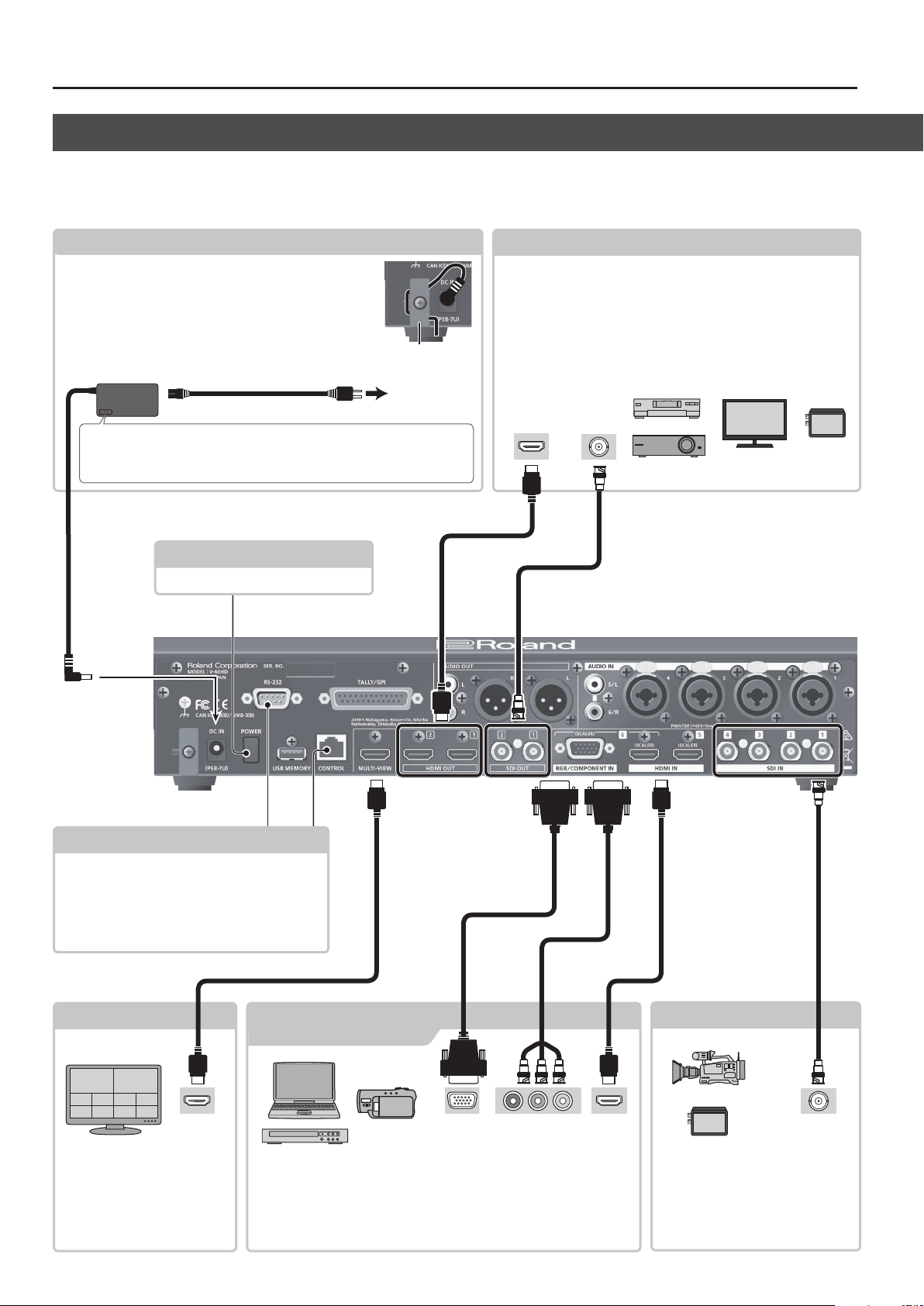
Rear Panel/Front Panel (Connecting Your Equipment)
* To prevent malfunction and equipment failure, always turn down the volume, and turn o all the units before making any connections.
* Be sure to use cables and adaptor plugs with the proper connectors matching those of the other devices you are using.
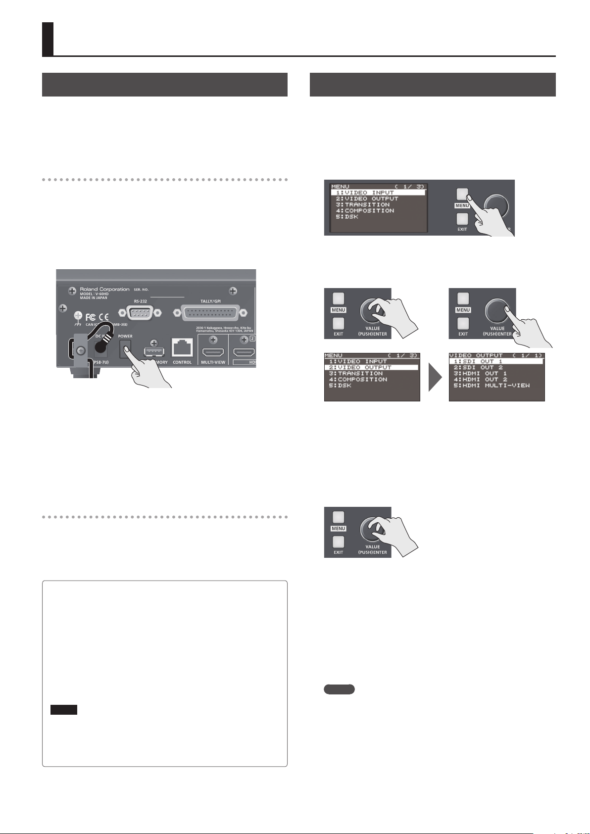
DC IN jack
Connect the included AC adapter to this jack.
* To prevent the inadvertent disruption of power to your
unit (should the plug be pulled out accidentally), and to
avoid applying undue stress to the jack, anchor the power
cord using the cord hook, as shown in the illustration.
Cord hook
AC adoptor
Place the AC adaptor so the side with the indicator (see illustration) faces
upwards and the side with textual information faces downwards. The
indicator will light when you plug the AC adaptor into an AC outlet.
Power cord
To AC outlet
[POWER] button
This turns the power on and o (p. 11).
SDI OUT 1 and 2 connectors, HDMI OUT 1 and 2 connectors
This outputs the results of video mixing (the nal-output video),
preview video (the video to be output next), or AUX-bus video.
Connect them to devices such as projectors, video recorders, or
external displays.
* The V-60HD has three internal output buses (PGM, PVW, and AUX),
and you can select the bus to output for each individual connector
(p. 15).
HDMI input
connector
SDI input
connector
RS-232 connector, CONTROL port
5 A remote-control device (such as a computer
that supports RS-232) can be connected here to
remotely control the V-60HD.
5 You use “V-60HD RCS” dedicated software to
operate the V-60HD remotely from a connected
computer (p. 34).
MULTI-VIEW connector
HDMI IN 5 and 6 connectors
RGB/COMPONENT IN 6 connector
HDMI input
connector
This outputs the input/output
video list, the audio level meter,
and the OSD menu (p. 10). You
connect a multi-view monitor
here.
These connectors input video signals from a computer or video devices
such as video cameras and DVD players.
* Channels 5 and 6 are allocated to the respective inputs.
* For channel 6, setting an assigned input connector is necessary (p. 13).
8
Analog RGB
output connector
Component
output connector
HDMI output
connector
SDI IN 1–4 connectors
SDI output
connector
These connectors input video signals
from video cameras, video recorders,
and other video equipment.
* Channels 1 through 4 are allocated
to the respective inputs.
Page 9
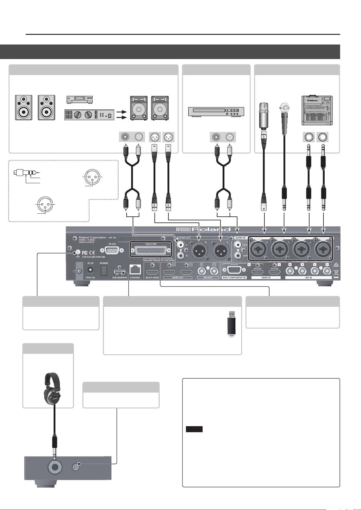
Panel Descriptions
3: COLD
2: HOT
1: GND
3: COLD
2: HOT
3: COLD
AUDIO OUT connectors/jacks (XLR and RCA)
These output the results of audio mixing (master out). Connect them to an audio
recording deck, amplier, speakers, or other such equipment.
* You can also output just AUX-bus audio
from the AUDIO OUT connectors and jacks
(XLR and RCA) and the PHONES jack (p. 25).
Pin assignment of AUDIO IN 1–4 jacks (XLR/TRS)
TIP: HOT
RING: COLD
SLEEVE: GND
Pin assignment of AUDIO OUT connectors (XLR)
1: GND
2: HOT
1: GND
phono plug
Audio input connectors Audio output connectors
RCA
AUDIO IN 5/6 jacks
These jacks input audio
signals from video decks, CD
players, and other such audio
equipment.
RCA
phono plug XLR plug
AUDIO IN 1–4 jacks (XLR/TRS)
These jacks input audio signals from
microphones, audio mixers, and other
such audio equipment.
Audio output connectors
1/4-inch TRS
phone plugXLR plug
Grounding terminal
Connect this to an external earth or
ground.
* Connect this if necessary.
PHONES jack
Connect headphones
to this jack.
[PHONES] knob
This adjusts the volume level for
headphones.
Stereo 1/4-inch
phone plug
Front Panel
USB MEMORY port
Connect a USB ash drive to this port. You use it when
importing still images (p. 19) or when saving or loading
settings for the unit (p. 32).
* When using a USB ash drive for the rst time, you
must format it using the V-60HD.
* Never turn o the power or remove the USB ash drive while
the USB ash drive is being accessed.
Using Phantom Power
You can supply phantom power (+48 V) from the AUDIO IN 1 through
4 jacks. Turn on phantom power when you’re using a condenser
microphone that requires phantom power.
Select the [MENU] button0“AUDIO INPUT”0“AUDIO IN 1” through
“AUDIO IN 4”0set “PHANTOM +48V ” to “ON.
NOTE
Always turn the phantom power o when connecting any device
other than condenser microphones that require phantom power.
You risk causing damage if you mistakenly supply phantom power
to dynamic microphones, audio playback devices, or other devices
that don’t require such power. Be sure to check the specications of
any microphone you intend to use by referring to the manual that
came with it.
(This instrument’s phantom power: 48 V DC, 14 mA Max)
TALLY/GPI connector
Connect devices provided with a tallylight feature or with control-signal output
functionality to this connector.
9
Page 10
Panel Descriptions
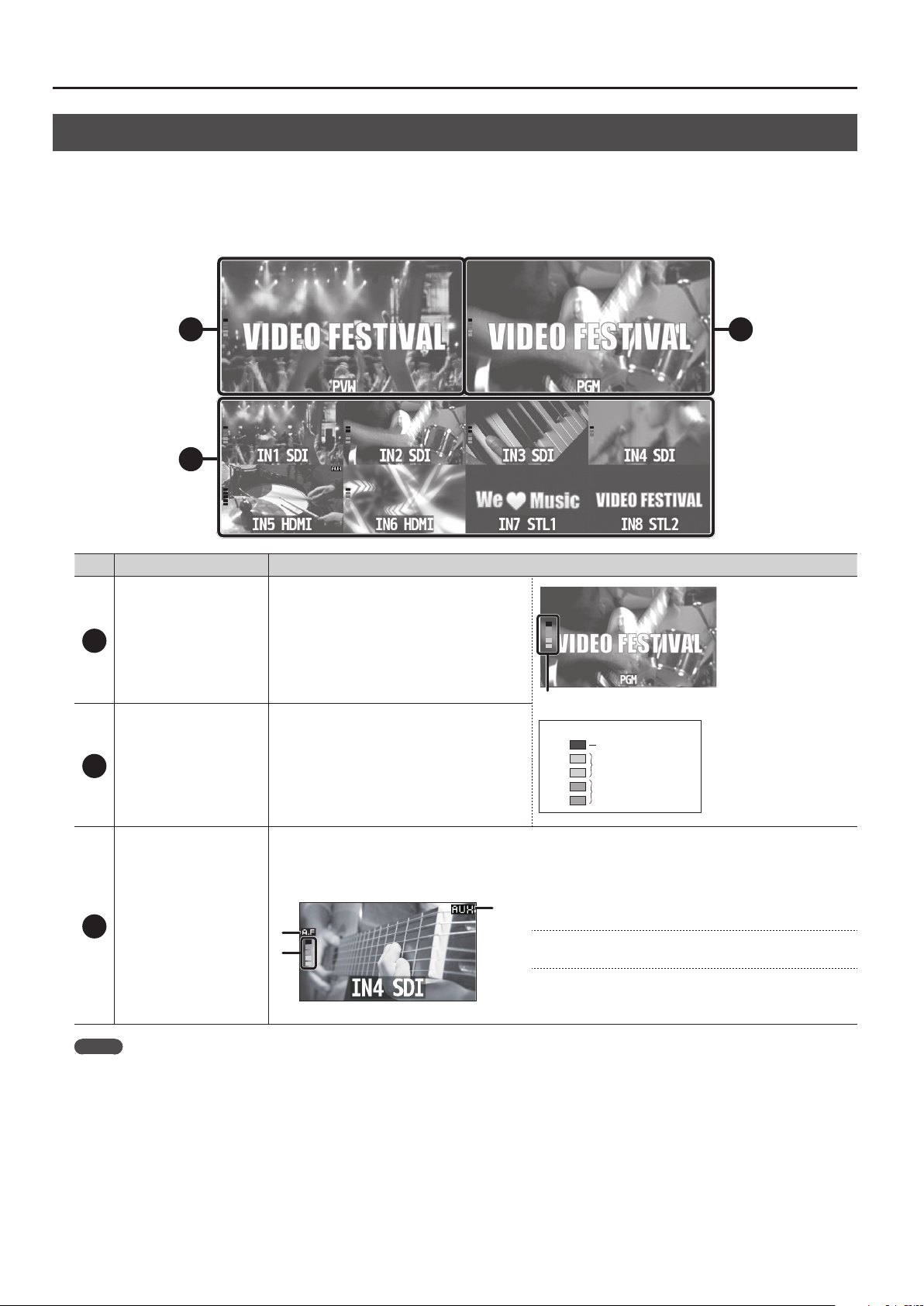
Multi-view Monitor Display
A list of input/output video streams, the audio level meter, and the OSD menu are displayed on the multi-view monitor connected to the
MULTI-VIEW connector.
* Pressing the [MENU] button displays the OSD menu. Its content is the same as the menu shown on the built-in display (p. 11). Label names,
tally borders, and the audio level meter are hidden while the OSD menu is displayed.
21
3
No Name Explanation
PVW (preview) section
1
PGM (program) section
2
3
Channel section
This displays the preset video (the video to be
output next).
This displays the level meter for master out.
(dB)
0
This displays the nal output video.
This displays video input via channels 1–6 and still images assigned to channels 7 and 8.
The nal video output and preset video (the video to be output next) are displayed with tally borders.
Channel information
2
1
3
-6
-20
-30
-50
When the Audio Follow feature is on (p. 29), the “A.F”
1
symbol is displayed.
When video or a still image is being sent to the AUX bus
2
(p. 18), the “AUX” symbol is displayed.
This displays a level meter for SDI or HDMI audio.
3
* The indicators for the level meter are the same as for
master out.
Red (Excessive)
Yellow (Suitable)
Green (Insucient)
MEMO
You can change the settings so that the label names, tally borders, audio level meter, OSD menu, and other such elements displayed on the
multi-view monitor are always hidden.
Select the [MENU] button0“SYSTEM,” then set the menu items shown below to “OFF.”
5 MULTI-VIEW LABEL (label names)
5 MULTI-VIEW TALLY (tally borders and AUX symbol)
5 AUDIO LEVEL METER (audio level meter and A.F symbol)
5 ON SCREEN MENU (OSD menu)
10
Page 11
Basic Operations
Turning the Power On and O
* Before turning the unit on/o, always be sure to turn the
volume down. Even with the volume turned down, you might
hear some sound when switching the unit on/o. However, this
is normal and does not indicate a malfunction.
Turning the power on
* If still images are saved on the unit (p. 18), startup takes longer
time according to image size and the number of still images
saved.
1. Make sure all devices are turned o.
2. Press the [POWER] button to turn on the power.
Operating the Menu
This makes menus appear on the built-in display for making
settings for video and audio or for the V-60HD itself.
* The OSD menu is similarly also displayed on the multi-view
monitor connected to the MULTI-VIEW connector (p. 10).
1. Press the [MENU] button to display the menu.
The [MENU] button is lit, and the menu categories are displayed.
2. Turn the [VALUE] knob to select a category, and press the
[VALUE] knob to conrm.
3. Turn on the power of the source devices.
Turn on the power of the source devices that are connected to the
V-60HD’s input connectors, such as video cameras.
4. Turn on the power of the output devices.
Turn on the power of the devices that are connected to the
V-60HD’s output connectors, such as projectors.
Turning the power o
1. Turn o the power in the order of output devices0source
devices.
2. Press the V-60HD’s [POWER] button to turn o the power.
About the Auto O function
The power to the V-60HD turns o automatically when all of the
following states persist for 240 minutes (Auto O function).
5
No operation performed on the V-60HD
5
No audio or video input
5
No equipment is connected to the HDMI OUT connectors
If you do not want the power to be turned o automatically,
disengage the Auto O function. Select the [MENU] button0
“SYSTEM”0set “AUTO OFF” to “OFF.”
NOTE
5 Any settings that you are in the process of editing will be lost
when the power is turned o. If you have any settings that you
want to keep, you should save them beforehand.
5 To restore power, turn the power on again.
The menu for the selected category is displayed.
3. Turn the [VALUE] knob to select a menu item, then press the
[VALUE] dial to conrm.
The cursor moves to the setting value.
5 If the menu item is located at a deeper level, repeat step 3.
5 Pressing the [EXIT] button moves you back one level higher.
4. Turn the [VALUE] knob to change the value of the setting.
5 By turning the [VALUE] knob while pressing it, you can change
the value more greatly.
5 Pressing and holding the [VALUE] knob returns the current
menu item you're setting to its default value.
5 To execute an operation, press the [VALUE] knob.
5. Press the [VALUE] knob to apply the setting.
The cursor returns to the menu item.
6. Press the [MENU] button to quit the menu.
MEMO
For details on the menu items, refer to the “Reference Manual”
(PDF) which you can download from the Roland website.
https://proav.roland.com/
11
Page 12
Video Input/Output Settings
Setting the Video Input/Output Format
Set parameters for the input/output format to match the connected equipment.
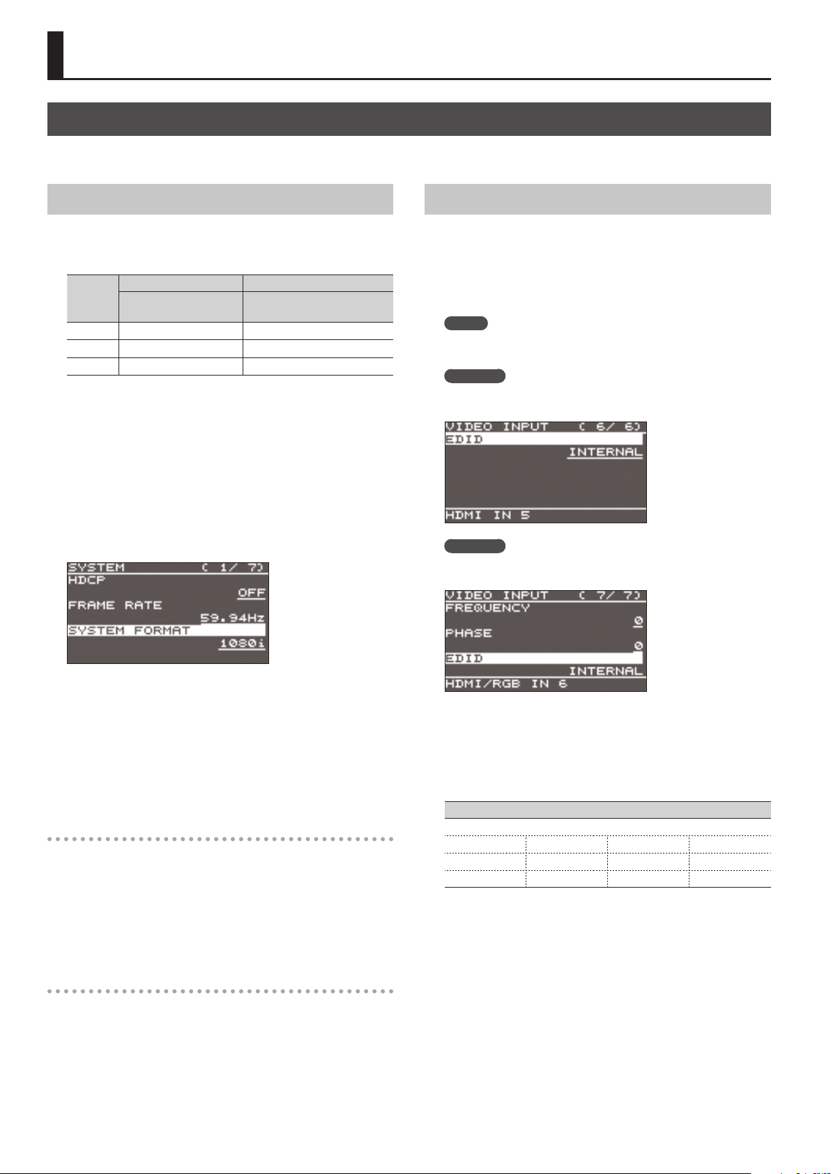
Setting the System Format
On the V-60HD, the input/output format is determined according
to the system format. You set the input/output format to match
the connected equipment.
System
format
1080p 1080p, 1080i 1080p
1080i 1080p, 1080i 1080i
720p 720p 720p
(*1) Input formats for channels 5 and 6
You can specify separate individual input formats for the
channel 5 and 6 input connectors (HDMI IN 5, HDMI IN 6, and
RGB/COMPONENT 6), regardless of the system format.
For details, refer to “Setting the Input Formats for Channels 5
and 6” on this page.
(*2) The output format at the MULTI-VIEW connector is xed at
“1080p” and cannot be changed.
1. Select the [MENU] button0“SYSTEM”0“SYSTEM FORMAT.”
Input format (*1) Output format (*2)
SDI IN 1–4 connectors
SDI OUT 1 and 2 connectors
HDMI OUT 1 and 2 connectors
Setting the Input Formats for Channels 5 and 6
By factory default, the EDID assignment for channels 5 and 6 is
“INTERNAL” (set so that EDID values of all inputtable formats are
sent).
To specify an input format of your choice, change the setting of
the EDID information being sent so that it matches the incoming
video signal.
MEMO
EDID information is not sent during component signal input.
Channel 5
1.
Select the [MENU] button0“VIDEO INPUT”0“HDMI IN 5”
0“EDID.”
Channel 6
Select the [MENU] button0“VIDEO INPUT”0“HDMI/RGB
IN 6”0“EDID.”
2. Use the [VALUE] knob to set the system format to “1080p,”
“1080i,” or “720p.”
3. Press the [VALUE] knob to apply the setting.
4. Press the [MENU] button to quit the menu.
Internal processing
The V-60HD’s internal processing is progressive. Interlaced input
video is automatically converted to a progressive signal.
The picture might appear jagged at this time, or the picture in a
PinP inset screen or on the multi-view monitor might waver.
This is due to progressive conversion, and is not a malfunction.
About frame rates
Frame rates that can be input are “59.94 Hz” and “50 Hz.”
Inputting video at a frame rate other than these might result in no
output or dropped frames.
To change the frame rate, press the [MENU] button0“SYSTEM”
0“FRAME RATE.”
* The settings on the HDMI/RGB IN 6 menu change in tandem with
the assignment made using “INPUT 6 ASSIGN” (p. 13). You can make
separate individual settings for the respective menu items for the
HDMI IN 6 connector and the RGB/COMPONENT IN 6 connector.
2. Use the [VALUE] knob to set the input format (the EDID
information to send).
Value
INTERNAL (EDID information for all inputtable formats is sent.)
800 x 600 1024 x 768 1280 x 800 1280 x 1024
1366 x 768 1400 x 1050 1600 x 1200 1920 x 1200
720p (*1) 1080i (*1) 1080p (*1)
(*1) For channel 6, this setting can be made only when “INPUT 6
ASSIGN” (p. 13) is set to “HDMI.”
3. Press the [VALUE] knob to apply the setting.
4. Press the [MENU] button to quit the menu.
12
Page 13
Video Input/Output Settings
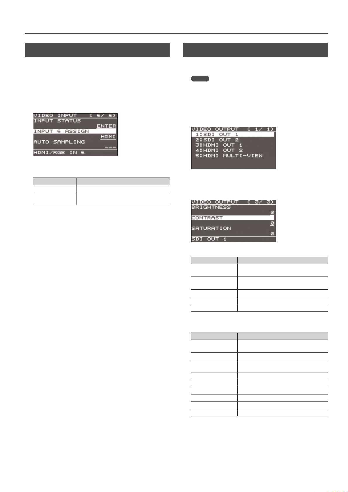
Assigning a Video Source to Channel 6
You can assign a video source at the HDMI IN 6 connector or the
RGB/COMPONENT IN 6 connector to channel 6.
You change the setting to match the connected source device.
* By factory default, the setting is for the HDMI IN 6 connector.
1. Select the [MENU] button0“VIDEO INPUT”0“HDMI/RGB
IN 6”0“INPUT 6 ASSIGN.”
2. Use the [VALUE] knob to specify the input connector to
assign to channel 6.
Value Explanation
HDMI Video is input via the HDMI IN 6 connector.
RGB/COMPONENT
3. Press the [VALUE] knob to apply the setting.
4. Press the [MENU] button to quit the menu.
Video is input via the RGB/COMPONENT IN 6
connector.
Adjusting Output Video
You can adjust the output video to match the equipment receiving
the output from the V-60HD.
MEMO
You can output a test pattern, useful for adjusting the image
quality of a display. You use the [MENU] button0“SYSTEM”
0“TEST PATTERN” to specify the test pattern.
1. Select the [MENU] button0“VIDEO OUTPUT”0the output
video.
A menu for the selected output video appears.
2. Select a menu item, then use the [VALUE] knob to adjust the
output video.
SDI OUT 1 and 2: SDI OUT 1 and 2 connectors
Menu item Explanation
3G-SDI MAPPING
H FLIP
BRIGHTNESS This adjusts the brightness.
CONTRAST This adjusts the contrast.
SATURATION This adjusts the saturation.
HDMI OUT 1 and 2: HDMI OUT 1 and 2 connectors
HDMI MULTI-VIEW: MULTI-VIEW connector
Menu item Explanation
COLOR SPACE
DVI-D/HDMI SIGNAL This sets the output mode for HDMI output.
H FLIP (*1)
BRIGHTNESS This adjusts the brightness.
CONTRAST This adjusts the contrast.
SATURATION This adjusts the saturation.
RED This adjusts the red level.
GREEN This adjusts the green level.
BLUE This adjusts the blue level.
(*1) HDMI OUT 1 and 2 only
This sets the mapping structure for 3G-SDI
output.
Setting this to “ON” ips the output video
horizontally.
This sets the color space (system for
representing colors in video).
Setting this to “ON” ips the output video
horizontally.
3. Press the [VALUE] knob to apply the setting.
4. Press the [MENU] button to quit the menu.
13
Page 14
Video Input/Output Settings
Adjusting the Input Video
This adjusts the image quality of the video input via the respective connectors. For HDMI IN and RGB/COMPONENT IN connectors, you can also
adjust the scaling.
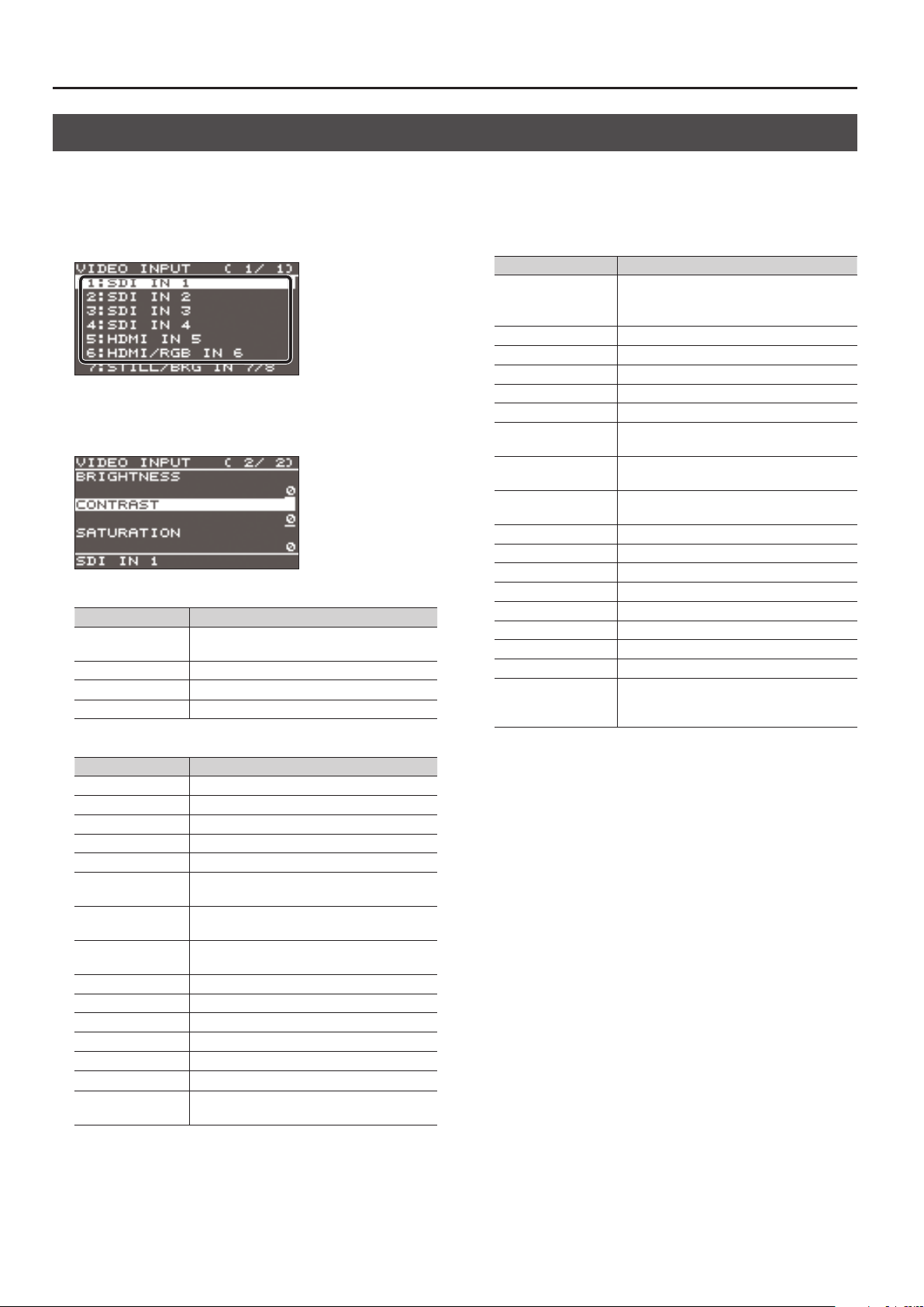
1. Select the [MENU] button0“VIDEO INPUT”0the input
video.
A menu for the selected input video appears.
2. Select a menu item, then use the [VALUE] knob to adjust the
input video.
SDI IN 1–4: SDI IN 1–4 connectors
Menu item Explanation
H FLIP
BRIGHTNESS This adjusts the brightness.
CONTRAST This adjusts the contrast.
SATURATION This adjusts the saturation.
HDMI IN 5: HDMI IN 5 connector
Menu item Explanation
FLICKER FILTER Setting this to “ON” reduces icker.
ZOOM This adjusts the zoom ratio.
SCALING TYPE This sets the scaling type.
MANUAL SIZE H (*1) This adjusts the horizontal size.
MANUAL SIZE V (*1) This adjusts the vertical size.
POSITION H
POSITION V
H FLIP
BRIGHTNESS This adjusts the brightness.
CONTRAST This adjusts the contrast.
SATURATION This adjusts the saturation.
RED This adjusts the red level.
GREEN This adjusts the green level.
BLUE This adjusts the blue level.
EDID
(*1) This is available when “SCALING TYPE” is set to “MANUAL.”
Setting this to “ON” ips the output video
horizontally.
This adjusts the display position in the
horizontal direction.
This adjusts the display position in the vertical
direction.
Setting this to “ON” ips the output video
horizontally.
This sets the input format (EDID) for the HDMI
IN 5 connector (p. 12).
HDMI/RGB IN 6: HDMI IN 6 connector (*2)
RGB/COMPONENT IN 6 connector (*2)
Menu item Explanation
This automatically adjusts the image quality.
AUTO SAMPLING (*3)
FLICKER FILTER Setting this to “ON” reduces icker.
ZOOM This adjusts the zoom ratio.
SCALING TYPE This sets the scaling type.
MANUAL SIZE H (*4) This adjusts the horizontal size.
MANUAL SIZE V (*4) This adjusts the vertical size.
POSITION H
POSITION V
H FLIP
BRIGHTNESS This adjusts the brightness.
CONTRAST This adjusts the contrast.
SATURATION This adjusts the saturation.
RED This adjusts the red level.
GREEN This adjusts the green level.
BLUE This adjusts the blue level.
FREQUENCY (*3) This adjusts the input frequency.
PHASE (*3) This adjusts the phase.
EDID
(*2) The settings on the HDMI/RGB IN 6 menu change in tandem
with the assignment made using “INPUT 6 ASSIGN” (p. 13). You
can make separate individual settings for the respective menu
items for the HDMI IN 6 connector and the RGB/COMPONENT IN
6 connector.
(*3) This is eective when “INPUT 6 ASSIGN” (p. 13) is set to “RGB/
COMPONENT.”
(*4) This is available when “SCALING TYPE” is set to “MANUAL.”
* Depending on the video, adjusting the
image quality might not be possible.
This adjusts the display position in the
horizontal direction.
This adjusts the display position in the
vertical direction.
Setting this to “ON” ips the output video
horizontally.
This sets the input format (EDID) of the
HDMI IN 6 connector or RGB/COMPONENT
IN 6 connector (p. 12).
3. Press the [VALUE] knob to apply the setting.
4. Press the [MENU] button to quit the menu.
14
Page 15

Video Input/Output Settings
Changing Output Bus Assignments
The V-60HD has three internal output buses (PGM, PVW, and AUX).
You can select which buses to output via the SDI OUT and HDMI
OUT connectors.
1. Select the [MENU] button0“VIDEO OUTPUT”0“SDI OUT 1,”
“SDI OUT 2,” “HDMI OUT 1,” or “HDMI OUT 2”
ASSIGN.”
2. Use the [VALUE] knob to select “PGM,” “PVW,” or “AUX” and
set the assigned output bus.
3. Press the [VALUE] knob to apply the setting.
4. Press the [MENU] button to quit the menu.
MEMO
5 For details about video transitions on the PGM/A bus and
PST/B bus, refer to “Switching Using the PGM/PST Mode” (p. 16)
and “Switching in the A/B Mode” (p. 17).
5 For details about video transitions on the AUX bus, refer to
“Switching AUX Output” (p. 18).
About audio outputs assigned to output buses
Changing an output bus assignment makes the output audio also
change in tandem, according to the assigned bus.
Output bus
assignment
PGM, PVW
AUX This outputs only the audio on the AUX bus.
* The audio of the MULTI-VIEW connector is xed at master out and
cannot be changed.
Output audio
This groups together all input audio and outputs
it (master out).
0“OUTPUT
Inputting Copyright-protected (HDCP) Video
To input copyright-protected (HDCP) video from a Blu-ray Disc
player or the like, follow the steps described below to change the
“HDCP” setting.
* The V-60HD must be connected to an HDCP compatible display
for HDCP protected video to be connected.
What’s HDCP?
HDCP is copyright-protection technology that prevents unlawful
copying of content by encoding the path when sending digital
signals from a video playback device to a display monitor or
other display equipment.
1. Select the [MENU] button0“SYSTEM”0“HDCP.”
2. Use the [VALUE] knob to set this to “ON.”
Value Explanation
Copyright-protected (HDCP) video can be input. HDCP is
ON
also added to the video that is output.
OFF Copyright-protected (HDCP) video cannot be input.
3. Press the [VALUE] knob to apply the setting.
4. Press the [MENU] button to quit the menu.
Output from connectors
When “HDCP” is set to “ON,” video is output only from the HDMI
OUT and MULTI-VIEW connectors.
No video is output via the SDI OUT connectors.
Operation of the HDCP indicator
The HDCP indicator operates as follows, regardless of input.
Indicator
Lighted ON
Flashing ON
Dark OFF —
“HDCP”
setting
Connection status
An HDCP-compatible device is connected to
the HDMI OUT or MULTI-VIEW connector.
No HDCP-compatible device is connected to
the HDMI OUT and MULTI-VIEW connectors.
Alternatively, a device that does not support
HDCP is connected.
15
Page 16

Video Operations
Switching the Video
This switches the video that is input into the V-60HD and performs nal output.
About the Operation Mode for Video Transitions
There are two operation modes for switching the video on the
PGM/A bus and PST/B bus: the “PGM/PST mode” and the “A/B mode.”
By factory default, the operation mode is set to the PGM/PST mode.
PGM/PST mode
The video on the PGM/A bus is always the nal output. The video
on the PST/B bus is preset video (the video to be output next).
Operating the video fader or the [CUT] or [AUTO] button makes
the nal video output and the preset video change places.
A/B mode
When the video fader is operated, the video at the bus position
toward which the video fader is ipped always becomes the nal
output.
When the [CUT] or [AUTO] button is operated, the video on the
PGM/A bus and the video on the PST/B bus become the nal
output in alternation.
MEMO
Video on the AUX bus is switched by operating the AUX/
MEMORY buttons.
For details, refer to “Switching AUX Output” (p. 18).
Switching Using the PGM/PST Mode
The video on the PGM/A bus is always the nal output. You use
the PST/B bus to select the preset video (the video to output next)
to verify it and then switch the video.
1. Flip the video fader all the way upward or downward.
2. Press one of the [WIPE 1], [WIPE 2], or [MIX] button to select
the transition eect.
The selected button lights up.
Mix ([MIX] button)
The two pictures are blended together as the
video is switched.
Wipe ([WIPE 1] and [WIPE 2] buttons)
In this transition, the original video is broken
into by the next video.
Setting the operation mode
1. Select the [MENU] button0“SYSTEM”0“PANEL OPERATION.”
2. Use the [VALUE] knob to select “PGM/PST” or “A/B” and set
the operation mode.
3. Press the [VALUE] knob to apply the setting.
4. Press the [MENU] button to quit the menu.
MEMO
You can change the transition pattern used for a wipe or mix
transition. Select the [MENU] button0“TRANSITION” 0 “MIX
TYPE,” “WIPE 1 TYPE,” or “WIPE 2 TYPE” to make the setting.
For a list of transition-pattern types, refer to “Transition Eects
List” (p. 42).
3. Press a cross-point button for the PST/B bus and select the
preset video (the video to be output next).
Lighted in red: Final output video
Lighted in green: Preset video (the video to
be output next)
The preset video appears in the PVW section of the multi-view
monitor.
MEMO
You use channels 7 and 8 to output a still image or a
monochrome picture (background color) (p. 18).
16
Page 17

Video Operations
4. Move the video fader in the direction opposite to the
direction in step 1.
Transition indicator
The video changes.
When the video has been switched completely, the cross-point
buttons for the PGM/A and PST/B buses change places.
MEMO
5 If the transition indicators are both lighted, move the video
fader all the way, so that only the indicator for the PGM bus
end or the PST bus end is illuminated.
5 Using a cross-point button for the PGM/A bus to select a
channel directly switches the video using a cut.
Using the [AUTO] or [CUT] button to switch video
You can use the [AUTO] or [CUT] button to switch video, without
using the video fader.
* You can perform operations using the [AUTO] and [CUT] buttons
both in the PGM/PST mode and in the A/B mode.
Switching in the A/B Mode
The video at the end to which the video fader is ipped is always
the nal output.
1. Flip the video fader all the way upward or downward.
2. Press a cross-point button at the end to which the video
fader is not ipped to select the preset video (the video to
output next).
Lighted in red: Final output video
Lighted in green: Preset video (the video to be output next)
The preset video appears in the PVW section of the multi-view
monitor.
MEMO
You use channels 7 and 8 to output a still image or a
monochrome picture (background color) (p. 18).
3. Press one of the [WIPE 1], [WIPE 2], or [MIX] button to select
the transition eect.
The selected button lights up.
1. Use the [TIME] knob to set the video transition time.
* The setting for the video transition time is applied when you
use the [AUTO] button to switch video.
2. Press the [AUTO] or [CUT] button at the desired timing for
switching the video.
Button Explanation
[AUTO] button
[CUT] button The picture switches instantly.
MEMO
When you use the [AUTO] or [CUT] button to switch video,
the actual output might come to dier from the position of
the video fader.
Operating the video fader while in this state yields no change
in output until the position of the video fader matches the
actual output.
A transition eect is applied and the video is
switched automatically. The [AUTO] button
ashes while the video transition is in progress.
4. Move the video fader in the direction opposite to the
direction in step 1.
Transition indicator
The video changes.
MEMO
5 If the transition indicators are both lighted, move the video
fader all the way, so that only the indicator for the bus end to
be output is illuminated.
5 Using a cross-point button for the nal-output bus to select a
channel directly switches the video using a cut.
17
Page 18

Video Operations
Switching AUX Output
You can use button operations to directly select the video to send
to the AUX bus.
You can output the video on the AUX bus from SDI OUT connectors
or HDMI OUT connectors. To output the AUX bus, you change the
bus assignments for the respective connectors to “AUX.”
For details, refer to “Changing Output Bus Assignments” (p. 15).
1. Press the [MODE] button to make it light up in green.
Each press of the [MODE] button makes it toggle between lighting
up in blue and in green.
Lit green
The AUX/MEMORY buttons function as AUX-bus selection buttons.
The AUX/MEMORY button currently selected as the video on the
AUX bus lights up in red.
2. Press an AUX/MEMORY button to select the AUX-bus video.
Using Imported Still Images
You can take a still image captured from input video or imported
from a USB ash drive, assign it to channel 7 or 8, and output it
in the same way as video. You can also use it as a source for DSK
compositing (p. 23).
You can save up to two still images in the unit.
* When still images are saved in the unit, startup takes longer
time according to image size and the number of still images
saved.
Capturing a Still Image from Input Video
This captures a still image from input video and saves it in the unit.
NOTE
5 All video input stops during still-image capture.
5 Depending on the format of the input video, completion of
still-image capture might take some time.
5 Created still images cannot be saved to a USB ash drive.
1. Select the [MENU] button0“CAPTURE IMAGE”0“CAPTURE
SOURCE,” then use the [VALUE] knob to specify the input
video to use for still-image capture.
The AUX output is switched.
MEMO
5 To adjust the volume level of audio on the AUX bus, select the
[MENU] button0“AUDIO OUTPUT”0“AUX”0adjust “AUX
LEVEL.”
5 You use channels 7 and 8 to output a still image or a
monochrome picture (background color) (p. 18).
5 On the multi-view monitor, the input channel sent to the AUX
bus is displayed with an “AUX” symbol.
The colors of lighted AUX/MEMORY buttons
When the [MODE] button is lighted in green, the AUX/MEMORY
buttons also function as indicators showing the status of video
input.
AUX/MEMORY [1] through [6] Buttons
Button Input video status
Lighted in green Valid video is input.
Flashing in green
Dark No video is input.
AUX/MEMORY [7] and [8] Buttons
Button Input video status
Lighted in green A still image has been imported.
Dark No still image has been imported.
MEMO
The AUX/MEMORY button for the currently selected video
lights up or ashes in red.
Video whose format diers from the system
format setting is input.
2. Press the [VALUE] knob to apply the setting.
3. Select “TARGET STORAGE NO,” then use the [VALUE] knob
to select “STILL IMAGE 1” or “STILL IMAGE 2” as the memory
destination for saving the still image.
A “ ” symbol is displayed for memory where a still image is already
saved.
4. Press the [VALUE] knob to apply the setting.
5. Select “CAPTURE EXECUTE.”
A conrmation message appears.
If you want to cancel the operation, press the [EXIT] button.
6. Use the [VALUE] knob to select “YES,” then press the [VALUE]
knob.
Capturing is carried out.
7. Press the [MENU] button to quit the menu.
MEMO
HDCP-applied video on HDMI IN 5 and 6
When you have captured from copyright-protected (HDCP)
video, the created still image is treated the same way as HDCPapplied video.
The still image is switched between displayed and hidden by
turning HDCP on and o (p. 15).
Note, however, that when HDCP is switched from o to on, the
still image is reloaded from where it's saved in memory, and so
the still image might take some time to display.
18
Page 19

Video Operations
Importing a Still Image from a USB Flash Drive
This imports into the unit a still image saved on a USB ash drive.
Supported still-image formats and resolutions
Still-image le formats that can be imported are as follows.
Explanation
Format Bitmap (.bmp), 24-bit color, uncompressed
Resolution In conformity with system format (p. 12)
File name
Importing a still image
NOTE
5 All video input stops while a still image is being
imported from a USB ash drive.
5 Large-size still-image les might take some time to import.
5 When you’re using a USB ash drive for the rst time, be sure to
format it on the V-60HD (p. 33).
5 Depending on the USB ash drive, recognition of the ash
drive might take some time.
1. Save the still image in the root directory of the USB ash
drive.
2. Connect the USB ash drive containing the saved still image
to the USB MEMORY port.
3. Select the [MENU] button0“USB MEMORY”0“LOAD STILL
IMAGE.”
No more than 8 single-byte alphanumeric characters
* Be sure to append the “.bmp” le extension.
Assigning Still Images to Channels 7 and 8
This takes a still image that has been captured or imported from a
USB ash drive, and assigns it to channel 7 or 8.
1. Select the [MENU] button0“VIDEO INPUT”0“STILL/BKG
7/8”0“INPUT 7 ASSIGN” or “INPUT 8 ASSIGN.”
2. Use the [VALUE] knob to select the memory where the still
image is saved.
A “ ” symbol is displayed for memory where a still image is already
saved.
3. Press the [VALUE] knob to apply the setting.
4. Press the [MENU] button to quit the menu.
MEMO
Assigning a monochrome picture (background color)
You can also assign a monochrome picture (background color)
to channel 7 or 8.
In step 2, set “INPUT 7 ASSIGN” or “INPUT 8 ASSIGN” to
“BACKGROUND.” Also, use “BACKGROUND COLOR” to specify
the background color.
* The background-color setting is shared by channels 7 and 8.
Deleting a Still Image
This deletes a still image saved in the unit.
4. Use the [VALUE] knob to select “STILL IMAGE 1” or “STILL
IMAGE 2” as the memory where the still image is saved.
A “ ” symbol is displayed for memory where a still image is already
saved.
5. Press the [VALUE] knob.
The USB LOAD screen appears. The names of the les on the USB
ash drive are displayed on this screen.
6. Select the still image le you want to import, then press the
[VALUE] knob.
A conrmation message appears.
If you want to cancel the operation, press the [EXIT] button.
7. Use the [VALUE] knob to select “YES,” then press the [VALUE]
knob.
The still image is imported into the unit.
8. Press the [MENU] button to quit the menu.
1. Select the [MENU] button0“SYSTEM”0“DELETE STILL
IMAGE.”
2. Use the [VALUE] knob to select “STILL IMAGE 1” or “STILL
IMAGE 2” as the memory you want to delete.
A “ ” symbol is displayed for memory where a still image is already
saved.
3. Press the [VALUE] knob.
A conrmation message appears.
If you want to cancel the operation, press the [EXIT] button.
4. Use the [VALUE] knob to select “YES,” then press the [VALUE]
knob.
The still image is deleted.
5. Press the [MENU] button to quit the menu.
19
Page 20

Video Operations
Applying a Fade to PGM/PVW Output Video (Output Fade)
This performs a fade-out from the output video to a black screen,
or a fade-in from a black screen to the output video.
You can insert a black screen into the output video at times
where you don’t want to output a picture, such as at intervals in
presentations or band performances.
MEMO
Fade-ins and fade-outs are applied to the nal video output
(program output) and the preset video (preview output).
Applying a fade to AUX-bus output is not possible.
1. Press the [OUTPUT FADE] button to perform a fade-out.
During the fade, the [OUTPUT FADE] button ashes.
When the fade-out is complete, the [OUTPUT FADE] button lights
up.
2. To perform a fade-in, press the [OUTPUT FADE] button again.
When the fade-in is complete, the [OUTPUT FADE] button goes
dark.
MEMO
5 The length of the fade-in or fade-out time uses the setting for
length transition time.
5 You can apply a fade-in and fade-out for both video and audio
at the same time. [MENU] button0“SYSTEM”0set “OUTPUT
FADE TYPE” to “VIDEO & AUDIO.”
20
Page 21

Video Composition Operations
This composites video. The V-60HD has three built-in types of composition.
Compositing Using Picture-in-Picture (PinP)
This composites video in an inset screen over a background video. This section describes operations when in the PGM/PST mode (p. 16).
Background videoInset screen
1. Press a cross-point button for the PGM/A bus to select the
video you want to make the background video.
2. Press a cross-point button for the PST/B bus to select the
video you want to make the inset screen.
5. Press the [AUTO] or [CUT] button.
The inset screen is composited onto the background video and
the result is sent to nal output. The [PinP 1] (or [PinP 2]) button
and the cross-point button for the PST/B bus light up in red.
Pressing the [AUTO] or [CUT] button a second time makes the
inset screen disappear.
MEMO
You can also display or hide the inset screen by operating the
video fader.
6. To turn o video composition, press the lighted [PinP 1] or
[PinP 2] button.
MEMO
The video transition-time setting is applied as the fade time
when you use the [AUTO] button to display or hide the inset
screen.
3. Press the [PinP 1] or [PinP 2] button to turn on video
compositing (making the button light up).
The selected button lights up in green and the inset screen
appears in the PVW section of the multi-view monitor, allowing
you to check the inset screen’s location and size.
At this stage, the nal output has not yet been changed.
4. Use the [H/PGM-CTR] and [V/PST-CTR] knobs to adjust the
display position of the inset screen.
[H/PGM-CTR] knob
This adjusts the inset screen’s display
position horizontally.
[V/PST-CTR] knob
This adjusts the inset screen’s display
position vertically.
Making detailed settings for the inset screen
You can use the [PinP 1] and [PinP 2] buttons to make settings
for the size and location of individual inset screens, and to make
setting such as for the width of borders added to the inset screens.
Select the [MENU] button0“COMPOSITION”0“PinP 1” or “PinP 2,”
then make the settings for the menu items shown below.
Menu item Explanation
This sets the size.
SIZE
POSITION H
POSITION V
BORDER COLOR
BORDER WIDTH This adjusts the border width.
SHAPE
ASPECT This species the aspect ratio.
For the inset screen, you select a horizontal width
of 1/2, 1/3, or 1/4 as the horizontal width of the
background video.
This adjusts the display position in the horizontal
direction.
This adjusts the display position in the vertical
direction.
This species the color of the border.
Setting this to “SOFT EDGE” blurs the edge.
This species the shape.
SQUARE CIRCLE HEART DIAMOND
21
Page 22

Video Composition Operations
A B
A B
A B
A B
A B
A B
A B
A
B
A
B
A B
A B
A B
A B
A
B
A
B
A
B
Compositing Using Split
This composites two video streams in a split screen. The nal output video is displayed above or on the left, and the preset video (the video to be
output next) is displayed below or on the right. This section describes operations when in the PGM/PST mode (p. 16).
Compositing using split
1. Press a cross-point button for the PGM/A bus to select the
video you want to display above or on the left.
Specifying a split composition pattern
2. Press a cross-point button for the PST/B bus to select the
This makes the settings for the split composition pattern to match
the video you want to composite.
1. Select the [MENU] button0“COMPOSITION”0“SPLIT”0
“PATTERN.”
video you want to display below or on the right.
2. Use the [VALUE] knob to specify the split composition
pattern.
Value Explanation
V-CENTER
H-CENTER
V-STRETCH This stretches the video vertically.
H-STRETCH This stretches the video horizontally.
This vertically crops the center section of
the video.
This horizontally crops the center section
of the video.
A
B
3. Press the [VALUE] knob to apply the setting.
4. Press the [MENU] button to quit the menu.
A B
3. Press the [SPLIT] button to turn on video compositing
(making the button light up).
The video you selected in steps 1 and 2 is composited.
A
B
* Previewing the results of the split composition in the PVW
section of the multi-view monitor is not possible.
4. Use the [H/PGM-CTR] and [V/PST-CTR] knobs to adjust the
display position of the video.
* You can carry out adjustment when “V-CENTER” or “H-CENTER”
is selected as the split composition pattern.
A
B
7 When Set to V-CENTER
This adjusts the display position in the horizontal direction.
[H/PGM-CTR] knob: Video on the left
[CV/PST-CTR] knob: Video on the right
7 When Set to H-CENTER
This adjusts the display position in the vertical direction.
[H/PGM-CTR] knob: Upper video
[V/PST-CTR] knob: Lower video
5. To turn o video compositing, press the [SPLIT] button a
second time.
22
Page 23

Video Composition Operations
Compositing Using DSK
This takes video composited upstream using PinP or the like, and performs further downstream compositing with text or images. Using DSK
(downstream keying), you can switch the background video while text or images remain displayed.
Compositing using DSK
1. Input the logo or image.
By factory default, the settings are such that text and image input
on channel 6 are used in DSK composition.
When you want to use text or image on another channel, use
the [MENU] button0“DSK”0 “DSK SOURCE CH” to change the
DSK
Setting the key type and extraction color
To change the key type and extraction color to match the video
you want to composite.
channel.
When you want to composite a still image saved in the unit (p. 18),
set this to “STILL/BKG IN 7” or “STILL/BKG IN 8.”
2. Output the background video.
At the PVW section of the multi-view monitor, check the video to
be made the background.
3. Press the [PVW] button to turn on the preview output (lighted).
1. Select the [MENU] button0“DSK”0“DSK TYPE.”
2. Use the [VALUE] knob to specify the key type (extraction
color) to use when compositing.
Value Explanation
LUMINANCE-WHITE
LUMINANCE-BLACK
CHROMA-GREEN
CHROMA-BLUE
This uses a brightness threshold to make
white transparent.
This uses a brightness threshold to make
black transparent.
This uses a color threshold to make green
transparent.
This uses a color threshold to make blue
transparent.
3. Press the [VALUE] knob to apply the setting.
4. Press the [MENU] button to quit the menu.
MEMO
When the key type is chroma key (“CHROMA-GREEN” or
“CHROMA-BLUE”), you can use the DSK menu to ne-tune the
key color.
Menu item Explanation
HUE WIDTH This adjusts the hue width (range).
HUE FINE This adjusts the center position for hue.
SATURATION WIDTH This adjusts the saturation width (range).
SATURATION FINE This adjusts the center position for saturation.
The [PVW] button lights up in green, and a preview of the
composition results is displayed in the PVW section of the multiview monitor.
At this stage, the nal output has not yet been changed.
4. Turn the [LEVEL] or [GAIN] knob to adjust the degree of
eect applied.
[LEVEL] knob
This adjusts the degree of extraction
(transparency) for the key.
[GAIN] knob
This adjusts the degree of edge blur
(semi-transmissive region) for the key.
5. Press the [DSK] button to turn on DSK composition (lighted).
The [DSK] button lights up in red, and the text or image is
composited and the results are output.
6. To turn o DSK compositing, press the [DSK] button a second
time.
The [DSK] button goes dark and the text and images disappear
from the output.
MEMO
5 The video transition-time setting is applied as the fade time for
DSK-composited text and image.
5 You can adjust the overall density of the text and images
being composited using DSK. Select the [MENU] button0
“DSK”0“MIX LEVEL” to adjust it.
23
Page 24

Audio Operations
Adjusting the Volume Level
This adjusts the head amp gain, sound position, and volume balance of audio input to the V-60HD.
Adjusting the Head Amp Gain
This adjusts the head amp gain so that the input audio is at a
suitable level.
* You can adjust the head amp gain only for AUDIO IN 1 through 4.
1. Adjust the AUDIO INPUT LEVEL knob for the input audio
whose head amp gain you want to adjust to a position near
“0 dB.”
2. Adjust the [MASTER OUTPUT] knob to a position near “0 dB.”
3. Select the [MENU] button0“AUDIO INPUT”0“AUDIO IN 1”
through “AUDIO IN 4”0“HEAD AMP GAIN.”
Adjusting the Sound Position (Pan)
The left-right position of audio is called the sound position (pan).
This lets you broaden the sound by moving its sound position
farther to the left and right at times such as when you’re
transmitting feed of a performance using two microphones.
* You can adjust the sound position only for AUDIO IN 1 through 4.
1. Select the [MENU] button0“AUDIO INPUT”0“AUDIO IN 1”
through “AUDIO IN 4”0“PAN.”
2. Use the [VALUE] knob to adjust the sound position.
3. Press the [VALUE] knob to apply the setting.
4. Press the [MENU] button to quit the menu.
* When adjusting the head amp gain, check to make sure the value
of “DIGITAL GAIN” is “0.0 dB.”
4. Turn the [VALUE] knob all the way counterclockwise to
lower the head amp gain.
5. Slowly turn the [VALUE] knob clockwise to adjust the head
amp gain.
Use the [VALUE] knob to gradually raise the head amp gain as you
play the actual incoming signal. Boost the head amp gain as high
as possible without making the SIG/PEAK indicator light up in red.
MEMO
SIG/PEAK Indicator Readings
Indicator Status
Red When input reaches the peak value (0 dB)
Green When input is detected (-50 dB or higher)
6. Press the [VALUE] knob to apply the setting.
7. Press the [MENU] button to quit the menu.
Adjusting the digital gain
On the V-60HD, separately from head amp gain, you can also adjust
“digital gain.” Whereas head amp gain adjusts analog audio, digital
gain adjusts digital audio.
With SDI or HDMI digital audio input, when audio at a high level is
input, eect processing can produce distortion.
Using digital gain lets you lower the input level so that eect
processing is not aected.
24
Page 25

Audio Operations
Adjusting the Volume Balance
This adjusts the volume balance of input and the volume level for
master out.
1. Adjust the [MASTER OUTPUT] knob to a position near “0 dB.”
2. While monitoring the audio via speakers or headphones,
adjust the volume balance for the respective inputs.
Raise the volume level of audio you want to make more prominent,
for example, an emcee microphone, and lower the volume level for
other audio.
When no audio is input, and for audio that is unused, lower the
volume level to minimum (-INF).
AUDIO IN 1–5/6
Use the AUDIO INPUT LEVEL knob to adjust the volume level.
SDI IN 1–4, HDMI IN 5 and 6
Select the [MENU] button0“AUDIO INPUT”0“SDI IN 1–4” or
“HDMI IN 5–6”0“INPUT LEVEL,” then use the [VALUE] knob to
adjust the volume level.
3. Use the [MASTER OUTPUT] knob to adjust the volume level
for master out.
Outputting AUX-bus Audio
You can output just AUX-bus audio from the AUDIO OUT jacks
(XLR and RCA) and the PHONES jack.
What’s AUX-bus audio?
Video and audio on video input channels selected using the
AUX/MEMORY buttons is sent to the AUX bus (p. 18).
When you assign the AUX bus to an audio output connector,
only the SDI or HDMI audio sent to the AUX bus is output.
1. Select the [MENU] button0“AUDIO OUTPUT”0“OUTPUT
ASSIGN”0“AUDIO OUT (XLR),” “AUDIO OUT (RCA),” or
“PHONES OUT.”
2. Use the [VALUE] knob to set this to “AUX.”
Value Explanation
MASTER OUTPUT
AUX This outputs only the audio on the AUX bus.
This groups together all input audio and
outputs it (master out).
A level at which indicators “-20”
through “-6” light up is appropriate.
Excessive
Suitable
Insucient
(dB)
* If the volume level of speaker output is not suitable even after
adjustment so that -20 to -6 light up, adjust the volume for the
speakers or the amplier. Using the [MASTER OUTPUT] knob
to carry out further adjustment might result in distortion or
degradation of sound quality.
MEMO
You can output a test tone, which is useful for adjusting the
volume level. Select the [MENU] button0“SYSTEM”0set
“TEST TONE” to “-20dB@1kHz,” “-10 dB@1kHz,” or “0dB@1kHz.”
3. Press the [VALUE] knob to apply the setting.
4. Press the [MENU] button to quit the menu.
MEMO
5 To adjust the volume level of audio on the AUX bus, select the
[MENU] button0“AUDIO OUTPUT”0“AUX”0adjust “AUX
LEVEL.”
5 For the SDI OUT and HDMI OUT connectors, changing the
assigned video bus makes the output audio also change in
tandem with it.
For details, refer to “Changing Output Bus Assignments” (p. 15).
* The audio of the MULTI-VIEW connector is xed at master
out and cannot be changed.
25
Page 26

Audio Operations
Applying Eects to Audio
You can apply eects and adjust the sound quality.
Applying Eects to Input Audio
This applies eects and adjusts the sound quality for AUDIO IN, SDI IN, and HDMI IN audio.
1. Select the [MENU] button0“AUDIO INPUT”0the input
audio.
2. Select an eect menu item, then use the [VALUE] knob to
adjust it.
* For more information about eects, refer to the following
section.
3. Press the [VALUE] knob to apply the setting.
4. Press the [MENU] button to quit the menu.
Compressor (COMP/LMT)
This compresses audio that exceeds a specied level.
Menu item Explanation
COMP/LMT This sets the compressor on or o.
THRESHOLD
RATIO
ATTACK
RELEASE
AUTO GAIN
MAKEUP GAIN
This sets the level used as the threshold at which the
compressor is applied. Compression is applied to
audio that exceeds the threshold.
This species the degree of compression applied
to the audio. The state in which no compression is
applied is dened as “1.”
This sets the time until compression starts when
audio exceeding the threshold is input.
This adjusts the length of time until compression
ends after audio falls below the threshold.
This switches the auto makeup gain feature on and o.
When this is set to “ON,” the nal output volume
level after applying the compressor is automatically
adjusted according to the “THRESHOLD” and “RATIO”
settings.
The total of the “MAKEUP GAIN” setting value
described below and the value calculated by auto
makeup gain becomes the nal output volume level
(up to +34 dB).
This adjusts the nal output volume level after
applying the compressor.
High-pass lter (HPF 75Hz)
This cuts o unneeded low-band audio. The cuto frequency is 75 Hz.
Menu item Explanation
HPF 75Hz This sets the high-pass lter on or o.
Delay (DELAY)
This outputs audio with a delay.
Delaying audio output lets you align the output timing of video
and audio.
Menu item Explanation
DELAY This adjusts the delay time for input audio.
Gate (GATE)
This mutes audio that is below a specied level.
Menu item Explanation
GATE This sets gate on or o.
THRESHOLD
RELEASE
This sets the level used as the threshold for removing
audio. Audio below the level set here is removed.
This adjusts the length of time until the audio is fully
attenuated after audio falls below the threshold.
MEMO
When the compressor is turned on, the COMP/LMT indicator
lights up while compression is applied to the input audio.
Equalizer (EQ)
This adjusts the sound quality for each frequency band.
Menu item Explanation
EQ Hi This boosts or attenuates the high band.
EQ Hi FREQ
EQ Mid This boosts or attenuates the middle band.
EQ Mid FREQ
EQ Mid Q
EQ Lo This boosts or attenuates the low band.
EQ Lo FREQ
This adjusts the center frequency when changing the
sound quality in the high band.
This adjusts the center frequency when changing the
sound quality in the middle band.
This adjusts the width of the frequency band when
boosting or attenuating the middle band.
This adjusts the center frequency when changing
the sound quality in the low band.
26
Page 27

Applying Eects to Output Audio
This applies eects and adjusts the sound quality for master out and AUX-bus audio.
* Only the limiter can be used on AUX-bus audio (p. 25).
Audio Operations
1. Select the [MENU] button0“AUDIO OUTPUT”0“MASTER
OUT” or “AUX.”
2. Select an eect menu item, then use the [VALUE] knob to
adjust it.
* For more information about eects, refer to the following
section.
3. Press the [VALUE] knob to apply the setting.
4. Press the [MENU] button to quit the menu.
Equalizer (EQ)
This adjusts the sound quality for each frequency band.
Menu item Explanation
EQ Hi This boosts or attenuates the high band.
EQ Hi FREQ
EQ Mid This boosts or attenuates the middle band.
EQ Mid FREQ
EQ Mid Q
EQ Lo This boosts or attenuates the low band.
EQ Lo FREQ
This adjusts the center frequency when changing
the sound quality in the high band.
This adjusts the center frequency when changing
the sound quality in the middle band.
This adjusts the width of the frequency band
when boosting or attenuating the middle band.
This adjusts the center frequency when changing
the sound quality in the low band.
* MASTER OUTPUT only
Multi-band compressor (MULTI BAND COMP)
* MASTER OUTPUT only
This applies separate compressors in individual frequency bands.
Menu item Explanation
MULTI BAND
COMP
Hi THRESHOLD
Mid THRESHOLD
Lo THRESHOLD
Hi RATIO
Mid RATIO
Lo RATIO
This switches the multi-band compressor on and
o.
These set the individual levels that become the
thresholds for the high, midrange, and low bands
at which the compressor is applied. Compression
is applied to audio that exceeds the threshold.
These set the amount of compression applied in
the high, midrange, and low bands. The state in
which no compression is applied is dened as “1.”
Limiter (LIMITER)
This limits the output volume so that is does not exceed the set
level.
Menu item Explanation
LIMITER This sets the limiter on or o.
This sets the level that becomes the threshold at
which the limiter is applied.
THRESHOLD
Compression is applied to audio that exceeds the
threshold. The volume level of audio that is output
is limited so as to stay to below the threshold.
27
Page 28

Audio Operations
Controlling Volume Levels Automatically (Auto Mixing)
This automatically controls operations that normally are performed
by an operator (Auto Mixing feature).
It lets you rely on the V-60HD to perform complex volumeadjustment operations, enabling use in circumstances where
no dedicated operator is assigned. This is especially useful for
meetings, discussions, debates, and other situations where
multiple microphones are used.
1. Follow the procedure in “Adjusting the Head Amp Gain”
(p. 24) to adjust the head amp gain for AUDIO IN 1 through 4.
2. Press the [AUTO MIXING] button to turn on the Auto Mixing
feature (making the button light up).
3. Select the [MENU] button0“AUDIO AUTO MIXING.”
Muting Out Specic Input Audio (Mute)
You can temporarily silence specic input audio (Mute feature).
Muting input audio
1. Select the [MENU] button0“AUDIO INPUT”0the input
audio.
2. Select “INPUT MUTE,” then use the [VALUE] knob to set it to
“ON.”
4. Select the audio to use with Auto Mixing, then use the
[VALUE] knob to set it to “ON.”
Set audio where Auto Mixing is not needed, such as background
music, to “OFF.”
5. Press the [VALUE] knob to apply the setting.
6. Set “WEIGHT,” then use the [VALUE] knob to set the priority
level for volume-level distribution (from 0 to 100%).
If there is audio that you want to make more prominent, such as
when you want to raise the volume level of an emcee microphone,
raise the weight level of that audio to emphasize it, and lower the
weight level for other audio.
MEMO
5 On audio to which Auto Mixing is applied, setting the weight
level to “0%” results in no audio output.
5 When air-conditioner noise or the like is a concern, set the
weight level to a low value.
7. Press the [VALUE] knob to apply the setting.
Repeat steps 4 through 7 as needed.
8. Press the [MENU] button to quit the menu.
9. To turn o the Auto Mixing feature, press the [AUTO
MIXING] button a second time.
To cancel muting, set this to “OFF.”
3. Press the [VALUE] knob to apply the setting.
4. Press the [MENU] button to quit the menu.
Muting output audio
This mutes out master out and AUX-bus audio (p. 25).
1. Select the [MENU] button0“AUDIO OUTPUT”0“MASTER
OUT” or “AUX.”
2. Select “OUTPUT MUTE” or “AUX MUTE,” then use the [VALUE]
knob to set it to “ON.”
To cancel muting, set this to “OFF.”
3. Press the [VALUE] knob to apply the setting.
4. Press the [MENU] button to quit the menu.
28
Page 29

Audio Operations
Interlinking Audio Output to Video Switching (Audio Follow)
You can associate audio with a video switch so that when the video is switched, the specied audio alone is output automatically, and other
audio is automatically muted.
NOTE
When the Audio Follow feature is turned on, switching between audio output and muting is carried out automatically.
The positions of the controls used to adjust the volume level do not change automatically.
1. Follow the procedure in “Adjusting the Volume Level” (p. 24)
to adjust to the volume level you want to output.
2. Select the [MENU] button0“AUDIO FOLLOW.”
3. Select the video channel you want to use with Audio Follow,
then use the [VALUE] knob to set it to “ON.”
Value Explanation
This enables the Audio Follow feature.
ON
OFF This disables the Audio Follow feature.
Muting is performed automatically when video on another
channel is output.
Applying audio follow to AUDIO IN 1–5/6
1. Select the [MENU] button0“AUDIO FOLLOW.”
2. From among “AUDIO IN 1” through “AUDIO IN 5/6,” select the
input audio you want to use with Audio Follow.
3. Use the [VALUE] knob to specify the video channel to use
with Audio Follow.
Value Explanation
SDI IN 1–4
HDMI IN 5
HDMI/RGB IN 6
STILL/BKG IN 7 and 8
OFF This assigns no video channel to Audio Follow.
4. Press the [VALUE] knob to apply the setting.
5. Press the [MENU] button to quit the menu.
This sets the video channel to interlink with
input audio using Audio Follow.
Audio from AUDIO IN 1–5/6 is muted out for
video channels other than what you specied.
4. Press the [VALUE] knob to apply the setting.
5. Press the [MENU] button to quit the menu.
6. Switch the video.
On video channels where Audio Follow is on, audio is automatically
muted when video on other channels is output.
MEMO
You can check the Audio Follow settings by examining the
channel section of the multi-view monitor. Video channels for
which Audio Follow is turned on are displayed together with
an “A.F” symbol.
29
Page 30

Audio Operations
Separating Discrete Analog Input Audio Streams and Adding Them to SDI Video
The SDI OUT connectors on the V-60HD accommodate eight channels of embedded audio. In addition to two channels for master out
(or the AUX bus), you can separate the six discrete channels of analog input audio (AUDIO IN 1 through 5/6) and add them to SDI video.
* The HDMI OUT connectors accommodate two channels of embedded audio (master out or the AUX bus).
The audio shown below is assigned to the respective channels of
SDI embedded audio.
SDI embedded-audio
channel number
Channel 1 Master out (L) or AUX bus (L)
Channel 2 Master out (R) or AUX bus (R)
Channel 3 AUDIO IN 1
Channel 4 AUDIO IN 2
Channel 5 AUDIO IN 3
Channel 6 AUDIO IN 4
Channel 7 AUDIO IN 5 (L)
Channel 8 AUDIO IN 6 (R)
Using this feature lets you separate up to six discrete channels of
analog input audio and add it to SDI video.
As a backup for visual or sound recording...
Digital audio is extracted from the SDI embedded audio one
channel at a time, so after visual recording or sound recording,
you can edit the audio channel by channel.
For multilingual support...
Taking multilingual narration or other such audio, making it
embedded audio and adding it to SDI video lets you later extract
and use the digital audio for the required language.
Assigned audio
1. Select the [MENU] button0“AUDIO EMBEDDED.”
2. From among “AUDIO IN 1” through “AUDIO IN 5/6,” select the
input audio you want to send to the SDI embedded-audio
channel.
3. Use the [VALUE] knob to set the audio type to “DRY” or “WET.”
Value Explanation
OFF No audio is sent.
DRY This sends the source audio with no eects applied.
WET This sends the eect-applied audio.
4. Press the [VALUE] knob to apply the setting.
Repeat steps 2 through 4 as needed.
5. Select “SDI OUT 1 AUDIO” or “SDI OUT 2 AUDIO,” then use
the [VALUE] knob to set it to “CH1–8.”
30
Audio containing channels 3 to 8 of embedded audio is output
from the SDI OUT connector set to “CH1–8.”
6. Press the [VALUE] knob to apply the setting.
7. Press the [MENU] button to quit the menu.
Page 31

Other Features
Saving/Recalling Settings (Preset Memory)
You can take the current settings, including video and audio settings and the state of the operation panel, and save them as a single set in
memory, for later recall and use when needed. The V-60HD is provided with eight preset memories.
About the last memory function
The V-60HD has a built-in Last Memory feature. Last Memory is a feature that saves the state of the unit that is in eect immediately before
power-down, and automatically restores the state at the next startup.
The Last Memory feature is enabled by default. When you want to call up a specied preset memory at startup, use the [MENU] button0
“PRESET MEMORY”0”START UP” to specify the memory number.
Saving to a preset memory
NOTE
When you have selected the [MENU] button0“PRESET
MEMORY”0“MEMORY PROTECT” and set this to “ON,” settings
cannot be saved to a preset memory.
1. Press the [MODE] button to make it light up in blue.
Each press of the [MODE] button makes it toggle between lighting
up in blue and in green.
Lit blue
The AUX/MEMORY buttons function as memory selection buttons.
The currently selected AUX/MEMORY button lights up in blue.
2. Press and hold (for 2 seconds or longer) the AUX/MEMORY
button for the number where you want to save the settings.
All AUX/MEMORY buttons briey light up in blue, and the current
settings are saved.
Recalling a preset memory
1. Press the [MODE] button to make it light up in blue.
Each press of the [MODE] button makes it toggle between lighting
up in blue and in green.
Lit blue
The AUX/MEMORY buttons function as memory selection buttons.
The currently selected AUX/MEMORY button lights up in blue.
2. Press the AUX/MEMORY button for the number whose
setting you want to recall.
The settings are recalled.
Deleting a preset memory
1. Select the [MENU] button0“PRESET MEMORY”0“DELETE.”
MEMO
5 The state of the [OUTPUT FADE] button and [PHONES] knob are
not saved to any preset memory. The [OUTPUT FADE] button is
always dark at startup.
5 The state of the [MODE] button and the settings shown below
are saved as global settings for the unit. They are not saved to
preset memories.
Category Setting items saved in the unit
RS-232/GPI
LAN CONTROL
SYSTEM
5 You can use the [MENU] button0“PRESET MEMORY” 0
“SAVE” or “LOAD” to save or load a preset memory.
All menu items
All setting items except “TEST PATTERN” and
“TEST TONE”
* “ TEST PATTERN” and “TEST TONE” are always
set to “OFF” at startup.
2. Use the [VALUE] knob to select the memory number
(1 through 8) that you want to delete, then press the
[VALUE] knob.
A conrmation message appears.
If you want to cancel the operation, press the [EXIT] button.
3. Use the [VALUE] knob to select “YES,” then press the [VALUE]
knob.
The preset memory is deleted.
4. Press the [MENU] button to quit the menu.
31
Page 32

Other Features
Saving the Unit’s Settings on a USB Flash Drive
You can group together the unit’s settings into a single le (*.V06) and save it to a USB ash drive connected to the USB MEMORY port. You can
access the saved le (*.V06) on the USB ash drive and load it into the unit for use when needed.
* When you’re using a USB ash drive for the rst time, be sure to format it on the V-60HD (p. 33).
* Depending on the USB ash drive, recognition of the ash drive might take some time.
Saving a new settings le
1. Select the [MENU] button0“USB MEMORY”0“SAVE AS
PRESET.”
2. With the cursor positioned at “ENTER,” press the [VALUE] knob.
The USB SAVE AS screen is displayed.
3. Enter the le name.
File name
Cursor
1. Use the [VALUE] knob to move the cursor.
Moving the cursor to a location where no character is present
increases the number of characters.
2. Press the [VALUE] knob to highlight the character at the cursor
location.
3. Use the [VALUE] knob to change the character, then press the
[VALUE] knob to accept the change.
5 Pressing the [EXIT] button deletes the character at the cursor
location.
5 You can enter a text string of up to 9 characters in length.
5 The extension of the le name is “V06.”
4. When you nish entering the name, use the [VALUE] knob to
select “SAVE,” then press the [VALUE] knob.
A conrmation message appears.
If you want to cancel the operation, press the [EXIT] button.
5. Use the [VALUE] knob to select “YES,” then press the [VALUE]
knob.
The le (*.V06) is newly saved on the USB ash drive.
6. Press the [MENU] button to quit the menu.
MEMO
Still images (p. 18) are not saved in the le (*.V06).
Overwrite-saving a settings le
1. Select the [MENU] button0“USB MEMORY”0“SAVE
PRESET.”
2. With the cursor positioned at “ENTER,” press the [VALUE] knob.
The USB SAVE screen is displayed.
3. Select the le to overwrite, then press the [VALUE] knob.
A conrmation message appears.
If you want to cancel the operation, press the [EXIT] button.
4. Use the [VALUE] knob to select “YES,” then press the [VALUE]
knob.
The le is saved by overwriting.
5. Press the [MENU] button to quit the menu.
Recalling
This loads settings that are in a preset memory (1 through 8)
saved on a USB ash drive. Loading settings overwrites the preset
memory on the unit.
1. Select the [MENU] button0“USB MEMORY”0“LOAD
PRESET.”
2. With the cursor positioned at “ENTER,” press the [VALUE] knob.
The USB LOAD screen is displayed.
3. Select the le (*.V06) you want to recall, then press the
[VALUE] knob.
A conrmation message appears.
If you want to cancel the operation, press the [EXIT] button.
4. Use the [VALUE] knob to select “YES,” then press the [VALUE]
knob.
The settings are recalled, and the values in the unit’s preset
memories are overwritten.
5. Press the [MENU] button to quit the menu.
32
Page 33

Other Features
Formatting USB Flash Drives
When using a USB ash drive for the rst time, be sure to format it
on the V-60HD.
NOTE
5 The V-60HD does not recognize unformatted USB ash drives.
5 Use a commercially available USB ash drive or a USB ash
drive sold by Roland. However, we cannot guarantee that all
commercially available USB ash drives will work with this unit.
5 Performing formatting causes all data already saved on
the USB ash drive to be deleted. If the ash drive contains
necessary data, back it up onto a computer or elsewhere
before formatting the drive.
Making the connection
1. Connect the USB ash drive to the USB MEMORY port.
Returning Settings to the Factorydefault State (Factory Reset)
You can return the values of settings on the V-60HD to their
factory defaults.
If operation that diers from what is described in the owner’s
manual occurs even when the steps described are followed
correctly, try performing a factory reset.
NOTE
Executing a factory reset causes all values that have been set,
settings saved in preset memories (p. 31), and still images
saved in the unit to be lost.
1. Select the [MENU] button0“SYSTEM”0“FACTORY RESET.”
A conrmation message appears.
If you want to cancel the operation, press the [EXIT] button.
2. Use the [VALUE] knob to select “YES,” then press the [VALUE]
knob.
A factory reset is executed.
3. Press the [MENU] button to quit the menu.
* Be careful to orient the USB ash drive correctly front and back
and in the correct direction for insertion, and insert it rmly, as
far as it will go. Never insert using undue force.
Performing formatting
1. Select the [MENU] button0“USB MEMORY”0“FORMAT.”
A conrmation message appears.
If you want to cancel the operation, press the [EXIT] button.
2. Use the [VALUE] knob to select “YES,” then press the [VALUE]
knob.
Formatting of the USB ash drive is carried out.
3. Press the [MENU] button to quit the menu.
33
Page 34

Other Features
Preventing Unintended Operation (Panel Lock)
This locks operation of buttons and knobs to prevent unintended
operation of the V-60HD.
1. Select the [MENU] button0“SYSTEM”0“PANEL LOCK.”
2. With the cursor positioned at “ENTER,” press the [VALUE] knob.
The PANEL LOCK menu appears.
3. Select a target for panel lock, then use the [VALUE] knob to
specify whether panel lock is applied (ON) or not applied
(OFF).
You can select the following menu items as targets for panel lock.
Menu item Target of panel lock
ALL SW & VOLUME All buttons and knobs
MENU SW + EXIT SW [MENU] and [EXIT] buttons
VALUE ENCODER [VALUE] knob
PGM/A 1–8 SW PGM/A bus cross-point [1]–[8] buttons
PST/B 1–8 SW PST/B bus cross-point [1]–[8] buttons
AUX/MEMORY 1–8 SW AUX/MEMORY buttons (All)
MODE SW [MODE] button
CUT SW + AUTO SW [CUT] and [AUTO] buttons
VIDEO FADER Video fader
OUTPUT FADE SW [OUTPUT FADE] button
DSK ON/OFF SW [DSK] button
COMPOSITION BLOCK
TRANSITION BLOCK
DSK BLOCK
AUDIO IN 1–6 VOLUME AUDIO INPUT LEVEL knobs (All)
AUTO MIXING SW [AUTO MIXING] button
MASTER OUTPUT VOLUME [MASTER OUTPUT] knob
4. Press the [VALUE] knob to apply the setting.
Repeat steps 3 and 4 as needed.
5. Press the [MENU] button to quit the menu.
6. Press and hold the [EXIT] button and the [MENU] button at
the same time (for 3 seconds or longer).
[H/PGM-CTR] and [V/PST-CTR] knobs
[PinP 1], [PinP 2], and [SPLIT] buttons
[MIX], [WIPE 1], and [WIPE 2] buttons
[TIME] knob
[LEVEL] and [GAIN] knobs
[PVW] button
The message “PANEL LOCKED” is displayed,
and panel lock is turned on. The button and
controls that you set to applied (ON) in step
3 are locked.
Operating the V-60HD by Remote Control
You can operate the V-60HD remotely from an external device.
Using the dedicated V-60HD RCS program
You can connect the V-60HD to a computer via a LAN or RS-232,
and use dedicated program V-60HD RCS to operate the unit by
remote control.
For more information about operation methods, refer to the
owner’s manual included with V-60HD RCS.
LAN
V-60HD RCS
RS-232
V-60HD RCS can be downloaded from the following Roland website.
https://proav.roland.com/
Using RS-232/LAN/GPI
You can operate the V-60HD remotely from an external device by
means of RS-232/LAN (CONTROL port)/GPI.
For the specications of the RS-232 connector and the TALLY/
GPI connector and for more information on operating the unit
remotely, refer to the Reference Manual (PDF), available for
download at the Roland website shown above.
Outputting a Tally Signal
You can output a tally signal from the TALLY/GPI connector.
A tally signal is output from the connector pin corresponding to
the video channel being output, also including video composition
and transition eects.
7. To turn o panel lock, again press and hold the [EXIT] button
and the [MENU] button at the same time (for 3 seconds or
longer).
The message “LOCK RELEASED” is displayed, and panel lock is
turned o.
34
For the specications of the TALLY/GPI connector, refer to the
Reference Manual (PDF), available for download at the Roland
website shown above.
Page 35

Appendices
Troubleshooting
If you suspect a malfunction, please check the following points. If this does not resolve the problem, contact a nearby Roland Service Center.
Problem Items to check Action Page
Video-related problems
No picture is input.
Video from the computer is not
displayed.
Video from the computer is
corrupted.
No picture is output.
“Snowy”-noise video is output.
The colors on the monitor
screen connected via HDMI are
incorrect.
HDMI output shown on a
display has its periphery cut
o.
Compositing a logo or video
cannot be accomplished.
Still-image cannot be
imported.
Audio-related Problems
No audio is output.
Audio volume is low.
Other Problems
Buttons and knobs cannot be
operated.
Switching is not complete even
when the video fader is moved.
A USB ash drive cannot be
read.
When the [MODE] button is lighted in green,
are the AUX/MEMORY buttons ashing in
green?
Has the video source been correctly
assigned to channel 6?
Is copyright-protected (HDCP) video being
input?
Is the format of the video output from the
computer compatible with the V-60HD’s
input formats?
When a rapidly moving video is input from
a computer, out-of-sync motion, icker, or
other picture corruption may occur.
Is “HDCP” set to “ON”?
Is the [OUTPUT FADE] button lighted?
Is the display connected correctly?
It is possible that the HDMI signal is not
being sent and received correctly.
Do the color-space settings for any
monitors connected to the HDMI OUT
connectors or the MULTI-VIEW connector
match the color-space setting on the
V-60HD?
Are the display settings compatible?
Has the correct key type (extraction color)
been selected for DSK?
Are you importing a still image whose
format and resolution are supported by
the V-60HD?
Does still image have a proper le name?
Is the volume turned down on the V-60HD?
Is head amp gain turned down for AUDIO
IN 1 through 4?
Is a condenser microphone connected?
Is panel lock turned on?
Factors such as continued use and
transportation can sometimes cause the
video to fail to be switched completely.
Has the USB ash drive been formatted on
the V-60HD?
Video in a format that diers from the setting on the V-60HD is being
input. Set the system format to match the connected device.
Specify the video source to assign to channel 6. p. 13
When inputting copyright-protected (HDCP) video signals, go to the
SETUP menu and set “HDCP” to “ON.”
The supported input formats on channels 1 through 4 are 1080p,
1080i, and 720p. Only channels 5 and 6 supports VESA-standard
resolutions.
This is called “tearing,” and does not indicate an equipment
malfunction.
When “HDCP” is set to “ON,” video is output only from the HDMI OUT
and MULTI-VIEW connectors. No video is output via the SDI OUT
connectors.
When the [OUTPUT FADE] button is lighted, a fade is applied to the
nal output video. To output the video, press the [OUTPUT FADE]
button to make it go dark.
When outputting copyright-protected (HDCP) video, connect an
HDCP-compatible” display.
Reconnect the HDMI cable. —
Use VIDEO OUTPUT menu0“HDMI OUT 1,” “HDMI OUT 2,” or “HDMI
MULTI-VIEW”0“COLOR SPACE” to change the setting.
Depending on the device, the color space might be interlinked with
the selection of DVI or HDMI or the selected format. In such cases,
changing the color space on the output device might bring about
improvement for the problem.
In the case of HDMI signals, automatic overscan occurs on some
displays. Change the display’s settings.
Go to the DSK menu and use “KEY TYPE” to select the key type
(extraction color) to match the background color of the logo or video.
Use the [LEVEL] and [GAIN] knobs to adjust the position to just the
right degree of extraction for the logo or image.
Still images of unsupported formats or resolutions are not
recognized. Prepare a still image whose format and resolution are
supported by the V-60HD.
Use a le name composed of no more than 8 single-byte
alphanumeric characters. Also, be sure to append the “*.bmp” le
extension. Still images without proper le names are not recognized.
Adjust each input to an appropriate volume level. Also, use the
[MASTER OUTPUT] knob to adjust the volume level for master out.
When head amp gain is turned down, no audio is output even when
the volume level is raised. Adjust the head amp gain.
When connecting a condenser microphone or other device requiring
phantom power, select the [MENU] button0“AUDIO INPUT” 0
“AUDIO IN 1” through “AUDIO IN 4”0set “PHANTOM +48V” to “ON.
When the message “OPERATION LOCKED” is shown on the built-in
display, panel lock is turned on.
Press and hold the [EXIT] button and the [MENU] button at the same
time (for 3 seconds or longer) to turn o panel lock.
Perform calibration of the video fader. Go to the SYSTEM menu, then
select and execute “VIDEO FADER CALIBRATE.”
The V-60HD does not recognize unformatted USB ash drives. Format
the USB ash drive before using it for the rst time.
p. 12
p. 15
p. 12
—
p. 15
p. 20
p. 15
p. 13
p. 23
p. 19
p. 25
p. 24
p. 9
p. 34
—
p. 33
—
—
35
Page 36

Appendices
Block Diagram
Video Section
SYSTEM FORMAT
1080p
1080i
720p
SDI IN 1
SDI IN 2
SDI IN 3
SDI IN 4
HDMI IN 5
HDMI IN 6
RGB/
COMPONENT IN 6
USB MEMORY
EDID
Emu
EDID
Emu
EDID
Emu
STILL IMAGE 1
STILL IMAGE 2
I/P
CONV
I/P
CONV
I/P
CONV
I/P
CONV
SCALER
SCALER
SCALER
FS
FS
FS
FS
FS
FS
FS
FS
CAPTURE
CAPTURE
CAPTURE
CAPTURE
CAPTURE
CAPTURE
CAPTURE
CAPTURE
1
2
3
4
INPUT
SELECT
5
6
7
AUX BUS
DSK SOURCE BUS
PGM/A BUS
PST/B BUS
36
BACKGROUND
COLOR
MULTI-VIEWER
8
PVW PGM
1 2 3
5 6 7
4
8
Page 37

Appendices
COMPOSITION
PinP
SPLIT
TRANSITION
WIPE
MIX
CUT
DSK
OUTPUT FADE
PGM
PVW
AUX
PGM
PVW
AUX
PGM
PVW
AUX
PGM
PVW
AUX
MENU
OSD
P/I
CONV
P/I
CONV
P/I
CONV
P/I
CONV
1080p
SDI OUT 1
SDI OUT 2
HDMI OUT 1
HDMI OUT 2
HDMI
MULTI-VIEW
37
Page 38

Appendices
Audio Section
INPUT BUS
AUDIO IN 1–4
PHANTOM
+48V
AUDIO IN 5/6
HEAD AMP
GAIN
A/D
DIGITAL
GAIN
DIGITAL
GAIN
HPF 75HzA/D
HPF 75Hz
SIG/PEAK LED
SIG/PEAK LED
L R
COMP/LMT LED
GATE
GATE DELAY
COMP EQ
COMP/LMT LED
COMP EQ
DELAY
WET
DRY
WET
DRY
WET
DRY
L R
INPUT
MUTE
OFF
INPUT
MUTE
OFF
OFF
INPUT
AUDIO
LEVEL
FOLLOW
TO “AUDIO IN 1–4 EMBEDDED”
INPUT
AUDIO
LEVEL
FOLLOW
TO “AUDIO IN 5 EMBEDDED”
TO “AUDIO IN 6 EMBEDDED”
AUTO
MIXING
AUTO
MIXING
PAN
SDI IN 1–4
HDMI IN 5/6
CH1 De-embedded
CH2 De-embedded
DIGITAL
GAIN
HPF 75Hz
LEVEL METER
L R
GATE DELAYCOMP
AUDIO
FOLLOW
INPUT
LEVEL
AUTO
MIXING
INPUT
MUTE
EQ
DELAY
AUX/MEMORY SW
* Same as video AUX selection
38
Page 39

FROM “AUDIO IN 1 EMBEDDED”
FROM “AUDIO IN 2 EMBEDDED”
FROM “AUDIO IN 3 EMBEDDED”
FROM “AUDIO IN 4 EMBEDDED”
FROM “AUDIO IN 5 EMBEDDED”
FROM “AUDIO IN 6 EMBEDDED”
MASTER OUTPUT
EMBEDDED
CH3–8
ON/OFF
EMBEDDED
CH3–8
ON/OFF
OUTPUT BUS
AUX
L R L R
* Same as video output bus
CH1 Embedded
CH2 Embedded
CH3 Embedded
CH4 Embedded
CH5 Embedded
CH6 Embedded
CH7 Embedded
CH8 Embedded
* Same as video output bus
CH1 Embedded
CH2 Embedded
CH3 Embedded
CH4 Embedded
CH5 Embedded
CH6 Embedded
CH7 Embedded
CH8 Embedded
Appendices
SDI OUT 1
SDI OUT 2
* Same as video output bus
CH1 Embedded
CH2 Embedded
CH1 Embedded
CH2 Embedded
CH1 Embedded
CH2 Embedded
LIMITER
MASTER OUTPUT LED
LEVEL METER
L R
MASTER
OUTPUT
MUTE
EQ
MULTI BAND
COMP
MASTER
OUTPUT
LEVEL
OUTPUT
FADE
D/A
AUX
MUTE
AUX
LEVEL
D/A
HDMI OUT 1
HDMI OUT 2
HDMI
MULTI-VIEW
AUDIO OUT
(XLR)
AUDIO OUT
(RCA)
LIMITER
PHONES LEVEL
PHONES OUT
D/A
39
Page 40

Appendices
Main Specications
Roland V-60HD: HD Video Switcher
9 Video
Video Processing 4:2:2 (Y/Pb/Pr), 8-bit
SDI IN 1–4
Input Connectors
Output Connectors
Input Formats
Output Formats
Video Eects
*1: The input interlaced video signal is converted to progressive video signal by internal processing.
*2: The video signal frame rate can be selected at the SYSTEM menu (59.94 Hz or 50 Hz).
*3: Conforms to SMPTE 296M, SMPTE 274M
*1 *2
HDMI IN 5–6
RGB/COMPONENT IN 6
SDI OUT 1–2
HDMI OUT 1–2
HDMI MULTI-VIEW
SDI IN 1–4
HDMI IN 5–6
RGB/COMPONENT IN 6
Still Image
SDI OUT 1–2
*2
HDMI OUT 1–2
HDMI MULTI-VIEW 1080/59.94p, 1080/50p
Transition CUT, MIX (DISSOLVE/FAM/NAM), WIPE (30 types)
Composition PinP (SQUARE, CIRCLE, HEART, DIAMOND), SPLIT (4 types), DSK (Luminance Key, Chroma Key)
Others Flip horizontal, Output fade, Still Image Capture, Still Image Playback, Test pattern output
*3
*3
BNC type x 4
* Conforms to SMPTE 424M (SMPTE 425M-AB), 292M
HDMI type A x 2
* HDCP Supported
* Multi-format Supported
HD DB-15 type x 1
* INPUT 6: HDMI or RGB/COMPONENT selected.
* Multi-format Supported
BNC type x 2
* Conforms to SMPTE 424M (SMPTE 425M-AB), 292M
HDMI type A x 2
* HDCP Supported
HDMI type A x 1
* HDCP Supported
720/59.94p, 720/50p (SYSTEM FORMAT: 720p)
1080/59.94i, 1080/50i, 1080/59.94p, 1080/50p (SYSTEM FORMAT: 1080i, 1080p)
480/59.94i, 576/50i, 480/59.94p, 576/50p, 720/59.94p, 720/50p, 1080/59.94i, 1080/50i, 1080/59.94p
1080/50p
VGA (640 x 480/60 Hz), SVGA (800 x 600/60 Hz), XGA (1024 x 768/60 Hz), WXGA (1280 x 800/60 Hz)
SXGA (1280 x 1024/60 Hz), FWXGA (1366 x 768/60 Hz), SXGA+ (1400 x 1050/60 Hz)
UXGA (1600 x 1200/60 Hz), WUXGA (1920 x 1200/60 Hz)
* The refresh rate is the maximum value of each resolution.
* Conforms to CEA-861-E,VESA DMT Version 1.0 Revision 11.
* 1920 x 1200/60 Hz: Reduced blanking
Bitmap File (.bmp)
* Maximum 1920 x 1080 pixels, 24-bit color, uncompressed.
* It can be stored up to 2 les in the internal memory.
720/59.94p, 720/50p (SYSTEM FORMAT: 720p)
1080/59.94i, 1080/50i (SYSTEM FORMAT: 1080i)
1080/59.94p, 1080/50p (SYSTEM FORMAT: 1080p)
9 Audio
Audio Processing Sampling rate 24 bits/48 kHz
SDI IN Linear PCM, 24 bits/48 kHz, 2ch (Conforms to SMPTE 299M)
Audio Formats
Input Connectors
Output Connectors
Input Level
SDI OUT Linear PCM, 24 bits/48 kHz, 8ch (Conforms to SMPTE 299M)
HDMI IN/OUT Linear PCM, 24 bits/48 kHz, 2ch
Digital
Analog
Digital
Analog
AUDIO IN 1–4 -60– +4 dBu (Maximum: +22 dBu)
AUDIO IN 5–6 -10 dBu (Maximum: +8 dBu)
SDI IN 1–4 BNC type x 4
HDMI IN 5–6 HDMI type A 19 pins x 2
Combo type (XLR, 1/4-inch TRS phone), phantom power
AUDIO IN 1–4
AUDIO IN 5–6 RCA phono type
SDI OUT 1–2 BNC type x 2
HDMI OUT 1–2 HDMI type A x 2
HDMI MULTI-VIEW HDMI type A x 1
AUDIO OUT XLR type
AUDIO OUT RCA phono type
PHONES Stereo 1/4-inch phone type
*4: DC 48 V (unloaded maximum), 10 mA (maximum load)
* Current value per channel
40
*4
Page 41

Appendices
Input Impedance
Output Level
Output Impedance
Audio Eects Auto Mixing, EQ, Delay, Compressor, HPF, Gate, Multi-Band Compressor, Limiter
9 Other Connectors
USB MEMORY USB A type (for USB drive)
Tally/GPI DB-25 type (Female, Tally: 12, GPI: 8)
RS-232 DB-9 type (Male, for Remote Control)
CONTROL RJ45 100BASE-TX (for Remote Control)
9 Other Functions
Preset Memory (8 types), Panel Lock Function, EDID Emulator, Smart Tally
9 Display
Graphic LCD: 128 x 64 dots
9 Other
Power Supply AC Adaptor
Current Draw 3.1 A
Power Consumption 37.0 W
Operation
Temperature
AUDIO IN 1–4 10 k ohms (HEAD AMP GAIN 0–23 dB), 5 k ohms (HEAD AMP GAIN 24–64 dB)
AUDIO IN 5–6 15 k ohms
AUDIO OUT (XLR) +4 dBu (Maximum: +22 dBu)
AUDIO OUT (RCA) -10 dBu (Maximum: +8 dBu)
PHONES 92 mW + 92 mW (32 ohms)
AUDIO OUT (XLR) 600 ohms
AUDIO OUT (RCA) 1 k ohm
PHONES 10 ohms
356 (W) x 221 (D) x 96 (H) mm
14-1/16 (W) x 8-3/4 (D) x 3-13/16 (H) inches
3.0 kg
6 lbs 10 oz
+0 to +40 degrees Celsius
+32 to +104 degrees Fahrenheit
Dimensions
Weight
(excluding AC adaptor)
Accessories Owner’s Manual, AC adaptor, Power cord
* 0 dBu=0.775 Vrms
* This document explains the specications of the product at the time that the document was issued. For the latest information, refer to the
Roland website.
Dimensions
356
208
96
Unit: mm
70 8
8.8°
208
221
40
41
Page 42

Appendices
Transition Eects List
MIX
Eect Explanation
MIX The two pictures are blended together as the video is switched.
FAM
NAM
WIPE
The original video is broken into by the next video.
Normal
H-DOWN H-UP V-RIGHT V-LEFT H-IN H-OUT V-IN V-OUT
Video transitions are made with the luminance levels of the two video streams maintained unchanged.
* This is an abbreviation of “full additive mix.”
The two video streams are compared, and transitions are made with display during transition starting with levels of high
luminance.
* This is an abbreviation of “non-additive mix.”
R-DOWN L-DOWN R-UP L-UP BLOCK V-GRID H-GRID
Soft Edge
H-DOWN s H-UP s V-RIGHT s V-LEFT s H-IN s H-OUT s V-IN s V-OUT s
R-DOWN s L-DOWN s R-UP s L-UP s BLOCK s V-GRID s H-GRID s
42
Page 43

IMPORTANT: THE WIRES IN THIS MAINS LEAD ARE COLOURED IN ACCORDANCE WITH THE FOLLOWING CODE.
For the U.K.
For the USA
For the USA
ENA 23 Zone 1 nr. 1620 Klaus-Michael Kuehnelaan 13, 2440 Geel, BELGIUMImporter:
BLUE: NEUTRAL
BROWN: LIVE
As the colours of the wires in the mains lead of this apparatus may not correspond with the coloured markings identifying the
terminals in your plug, proceed as follows:
The wire which is coloured BLUE must be connected to the terminal which is marked with the letter N or coloured BLACK.
The wire which is coloured BROWN must be connected to the terminal which is marked with the letter L or coloured RED.
Under no circumstances must either of the above wires be connected to the earth terminal of a three pin plug.
FEDERAL COMMUNICATIONS COMMISSION
RADIO FREQUENCY INTERFERENCE STATEMENT
This equipment has been tested and found to comply with the limits for a Class B digital device, pursuant to Part 15 of the FCC Rules.
These limits are designed to provide reasonable protection against harmful interference in a residential installation. This equipment
generates, uses, and can radiate radio frequency energy and, if not installed and used in accordance with the instructions, may cause
harmful interference to radio communications. However, there is no guarantee that interference will not occur in a particular
installation. If this equipment does cause harmful interference to radio or television reception, which can be determined by turning
the equipment o and on, the user is encouraged to try to correct the interference by one or more of the following measures:
– Reorient or relocate the receiving antenna.
– Increase the separation between the equipment and receiver.
– Connect the equipment into an outlet on a circuit dierent from that to which the receiver is connected.
– Consult the dealer or an experienced radio/TV technician for help.
This device complies with Part 15 of the FCC Rules. Operation is subject to the following two conditions:
(1) this device may not cause harmful interference, and
(2) this device must accept any interference received, including interference that may cause undesired operation.
This equipment requires shielded interface cables in order to meet FCC class B limit.
Any unauthorized changes or modications not expressly approved by the party responsible for compliance could void the user’s
authority to operate the equipment.
CAN ICES-3 (B)/NMB-3 (B)
Manufacturer:
Type of Equipment :
Responsible Party :
2036-1 Nakagawa, Hosoe-cho, Kita-ku, Hamamatsu, Shizuoka 431-1304, JAPAN
Model Name :
Address :
Telephone :
For Canada
For Korea
DECLARATION OF CONFORMITY
Compliance Information Statement
V-60HD
VIDEO SWITCHER
Roland Corporation U.S.
5100 S. Eastern Avenue Los Angeles, CA 90040-2938
(323) 890-3700
43
Page 44

* 5 1 0 0 0 5 7 5 2 6 - 0 2 *
For EU Countries
 Loading...