

Page 1
9 Support for the following functions is planned via an
update.
5 Output Freeze function
9 Recommended cables
When inputting or outputting 4K resolution video (2160p (UHD),
2160p (DCI), 3840x2160, 4096x2160), please use premium highspeed HDMI cables and SDI cables that support 12G SDI.
Reference Manual
Update History .......................................... 2
Panel Descriptions ...................................... 3
Top Panel / Side Panel ..................................... 3
Rear Panel / Front Panel (Connecting Your Equipment) ....... 5
Multi-View Monitor Display ................................ 7
Basic Operations ........................................ 8
Turning the Power On/O .................................. 8
Using the Menus .......................................... 8
List of Supported Formats .............................. 9
Input Formats ............................................. 9
Output Formats ........................................... 9
Video Input/Output Settings ........................... 10
Setting the Output Format ................................. 10
Assigning a Video Source to Input Channels ................. 10
Sharing a Video Source .................................... 10
Assigning a Bus to an Output Connector .................... 11
Adjusting Final Output Video ............................... 11
Adjusting the Input Video .................................. 12
Inputting Copyright-protected (HDCP) Video ................ 13
Specifying a Reference Clock ............................... 14
Video Operations ....................................... 15
Switching the Video ....................................... 15
Using Imported Still Images ................................ 16
Applying a Fade to the Final Output Video (Output Fade). . . . . 17
Video Composition Operations ......................... 18
Compositing Using Picture-in-Picture (PinP) ................. 18
Compositing Using Luminance Key/Chroma Key ............ 19
Audio Operations ....................................... 21
Adjusting the Input/Output Volume ........................ 21
Muting the Input Audio .................................... 21
Matching the Timing of the Input/Output Audio with the Video
........................................................21
Interlinking Audio Output to Video Switching (Audio Follow) . 21
Applying Audio Follow to AUDIO IN ........................ 21
Mixing Input Audio with HDMI Video or SDI Video ........... 22
Other Operations ....................................... 23
Saving/Recalling Settings (Memory) ........................ 23
Saving the Unit’s Settings to File on a USB Flash Drive ........ 24
Formatting USB Flash Drives ............................... 25
Changing Cross-point Assignments ......................... 25
Returning Settings to the Factory-default State (Factory Reset)
........................................................25
Menu List ................................................ 26
Signal Status .............................................. 27
Input ..................................................... 29
Output ................................................... 31
Transition ................................................. 32
Composition .............................................. 33
DSK ...................................................... 35
Audio .................................................... 37
USER ..................................................... 40
System ................................................... 41
LAN/RS-232 Command Reference ...................... 44
LAN Interface ............................................. 44
RS-232 Interface ........................................... 44
Command Format ......................................... 44
List of Commands ......................................... 45
Control Using the TALLY/GPI Connector ................ 46
Specication of the TALLY/GPI Connector ................... 46
Inputting a Control Signal .................................. 46
Outputting a Tally Signal ................................... 46
Appendix ................................................ 47
Troubleshooting .......................................... 47
Main Specications ........................................ 48
Dimensions ............................................... 50
VIDEO Block Diagram ...................................... 51
AUDIO Block Diagram ..................................... 52
© 2019 Roland Corporation
02
Page 2

Update History
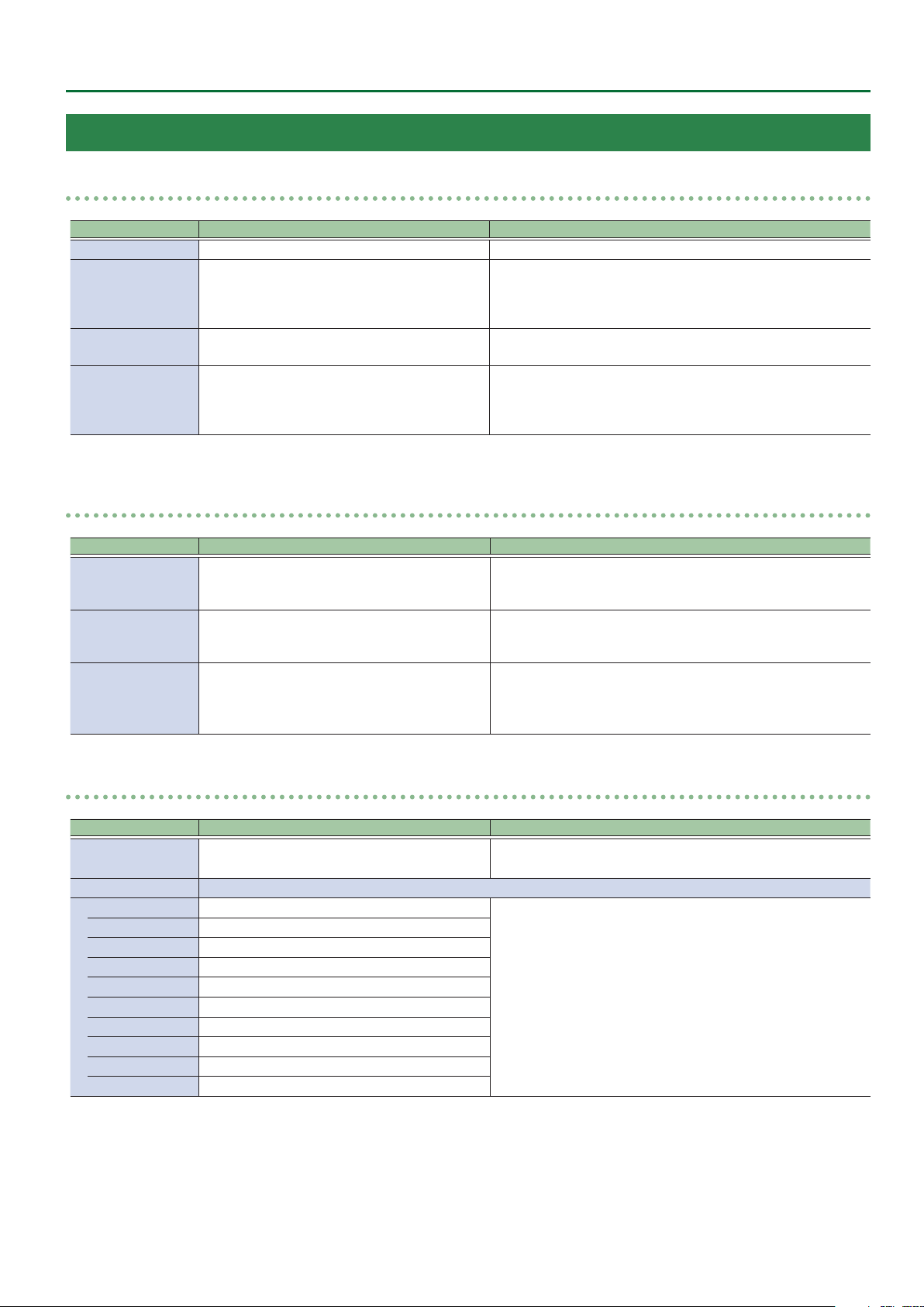
Ver.1.07
Additional functions
5 SDI OUT 3G Level B output
5 Functions that use the RS-232 connector and LAN port
5 SDI IN audio functionality (*)
*: Immediately after updating to Ver.1.07, the SDI IN audio parameter is muted.
If you want to use SDI IN audio, perform one of the following operations.
– In MENU 0 Audio 0 SDI IN 5/6 screen, edit the Mute, Level, Aux Send, and Mix Ch.1–16 parameters.
– Execute Factory Reset.
Ver.1.06
Functionality improvements
5 The stability of HDMI and SDI input and output has been improved.
5 The display of signal status when a Mac computer is connected has been improved.
Ver.1.05
Bug x
5 The possibility that in extremely rare cases signals to HDMI IN might fail to be received correctly has been circumvented.
2
Page 3
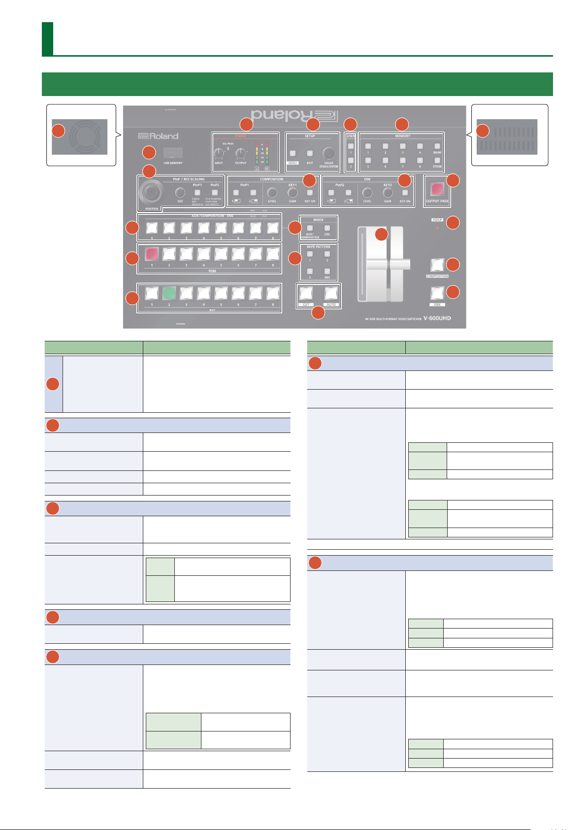
Panel Descriptions
Top Panel / Side Panel
Side panel
20
1
6
9
10
11
Name Explanation
This is for connecting a USB ash drive. You use
this when importing still images, or when saving
USB MEMORY port
1
2
AUDIO
[INPUT] knob
SIG/PEAK indicator
[OUTPUT] knob
Level meter
3
SETUP
[MENU] button
[EXIT] button
[VALUE] knob
4
USER
[1], [2] buttons
5
MEMORY
[1]–[8] buttons
[BANK] button
[STORE] button
or loading settings.
* Never turn o the power or remove the USB
ash drive while the USB ash drive is being
accessed.
Adjusts the volume level (digital gain) for AUDIO
IN L/R.
Lit green when input is detected at AUDIO IN L/R,
and lit red when the volume is excessive.
Adjusts the audio output/headphones volume.
Indicates the audio output (L/R) volume level.
Switches between displaying or hiding the menu.
The menu appears on the multi-view monitor
connected to the MULTI-VIEW connector.
Returns you to the menu one level higher.
Selects a menu item or changes a
Turning
setting value.
Accepts the selected menu item or
Pressing
applies changes to a setting. It also
executes operations.
Execute the functions that are assigned by the
menu settings.
Save the current settings (such as video settings
and operating panel status) to memory, or recall
settings from memory.
Button functioning is switched according to
whether the [STORE] button is on/o.
[STORE] on (lit)
[STORE] o (unlit)
When this is turned on (lit), the [1]–[8] buttons
function as bank selection buttons for memories.
When this is turned on (lit), you can save settings
in memories.
2
Saves current settings in
memory.
Recalls settings that are saved
in memory.
Side panel
3
4
12
13
7
14
15
5
8
16
17
21
18
19
Name Explanation
6
PinP / ROI SCALING
[POSITION] stick
[SIZE] knob
[PinP1], [PinP2] buttons
(*1)
* When selecting “ROI,” you can adjust the input video selected as the preset video.
7
COMPOSITION (*1)
PinP1 [1], [2] buttons
KEY1 [LEVEL] knob
KEY1 [GAIN] knob
KEY1 [KEY ON] button
Adjusts the display position of the input video or
PinP inset screen.
Enlarges or reduces the size of the input video or
PinP inset screen.
Select what is controlled by operating the
[POSITION] stick and [SIZE] knob.
[PinP1] button
Lit green PinP1 window
Lit red
Lit magenta
[PinP2] button
Lit green PinP2 window
Lit red
Lit magenta
Turns picture-in-picture video compositing on/
o. The selected button lights up when it is
switched on.
The color of the lit button indicates the output
destination of the compositing results.
Lit green PinP1 composition on
Lit red Final output
Unlit PinP1 composition o
During key compositing, this adjusts the amount
of keying (transparency).
During key compositing, this adjusts the degree
of edge blur (the semi-transmissive region) for
keying.
Turns key composition on/o.
When on, the KEY1 [KEY ON] button lights up.
The color of the lit button indicates the output
destination of the compositing results.
Lit green KEY1 composition on
Lit red Final output
Unlit KEY1 composition o
Video shown in the PinP1 inset
screen
ROI (input video)
Video shown in the PinP2 inset
screen
ROI (input video)
3
Page 4
Panel Descriptions
Name Explanation
8
DSK
Turns picture-in-picture video compositing on/
o. The selected button lights up when it is
switched on.
PinP2 [1], [2] buttons
KEY2 [LEVEL] knob
KEY2 [GAIN] knob
KEY2 [KEY ON] button
9
AUX/COMPOSITION - DSK
Cross-point [1]–[8]
buttons (*2)
10
PGM
Cross-point [1]–[8]
buttons
11
PST
Cross-point [1]–[8]
buttons
The color of the lit button indicates the output
destination of the compositing results.
Lit green PinP2 composition on
Lit red Final output
Unlit PinP2 composition o
During key compositing, this adjusts the amount
of keying (transparency).
During key compositing, this adjusts the degree
of edge blur (the semi-transmissive region) for
keying.
Turns key composition on/o. When on, the KEY2
[KEY ON] button lights up.
The color of the lit button indicates the output
destination of the compositing results.
Lit green KEY2 composition on
Lit red Final output
Unlit KEY2 composition o
Indicates the status of video input to the crosspoints.
Here you can also select the video that is sent
to the destination specied by the MODE [AUX/
COMPOSITION] button and [DSK/ROI] button.
Unlit Video is not being input.
Lit green Valid video is being input.
Lit red
Lit yellow
Lit blue
Selects the nal output video.
The button of the channel for nal output is lit
red.
Selects the preset video (the video to output
next). The button of the channel for preset video
is lit green. While compositing of the video is in
progress it lit red.
* When the menu is not shown, you can hold
Video is being sent to AUX.
You can use the [1]–[8] buttons to
change the video that is sent to AUX.
Video is being sent to COMPOSITION.
You can use the [1]–[8] buttons to
change the video that is sent to
COMPOSITION.
Video is being sent to DSK.
You can use the [1]–[8] buttons to
change the video that is sent to DSK.
down the [MENU] button and press a PST crosspoint [1]–[8] button to successively switch the
input source setting.
Name Explanation
12
MODE
Selects the destination of the video.
The video selected by the AUX/COMPOSITION -
DSK cross-point [1]–[8] button is sent.
[AUX/COMPOSITION]
button
[DSK] button (*2)
13
WIPE PATTERN
[1]–[3] buttons
[MIX] button
[CUT] button
14
[AUTO] button
Video fader
15
[OUTPUT FADE]
16
button
HDCP indicator
17
[COMPOSITION]
18
button
[DSK] button
19
Cooling-fan exhaust
20
port
Cooling-fan intake
21
port
*1 COMPOSITION (PinP1/KEY1) operation is not possible if the Aux/Composition
setting (p. 41) is “Aux.”
*2 Only AUX can be selected if the Aux/Composition (p. 41) setting is “Aux,”
and only COMPOSITION can be selected if the Aux/Composition setting is
“Cpmposition.”
[AUX/COMPOSITION] button
Lit red AU X
Lit yellow COMPOSITION
[DSK] button
Lit blue DSK
Selects the video transition eects. The selected
button lights up.
The original video is broken into by the
[1]–[3]
next video.
The two pictures are blended together
[MIX]
as the video is switched.
Makes the preset video (the video to output next)
the nal output.
[CUT] The picture switches instantly.
The picture switches with a transition
[AUTO]
eect applied.
Makes the preset video (the video to output next)
the nal output.
Performs a fade-in or fade-out for the nal
output video.
Lit Fade-out
Blink Fade-in/fade-out in progress
Unlit Normal output
This lights up, blinks, or becomes unlit according
to HDCP (High-bandwidth Digital Content
Protection) settings and the connection status of
HDCP-compatible equipment.
If this is on (lit), the composited result
COMPOSITION (PinP1/KEY1) is the nal output.
If this is on (lit), the composited result DSK
(PinP2/KEY2) is the nal output.
Expels internal heat to keep temperatures inside
the V-600UHD cool.
NOTE
Do not block the cooling-fan intake and exhaust
ports. Blocking the intake and exhaust ports
might result in a temperature rise inside the
V-600UHD and lead to malfunction due to heat.
4
Page 5
Panel Descriptions
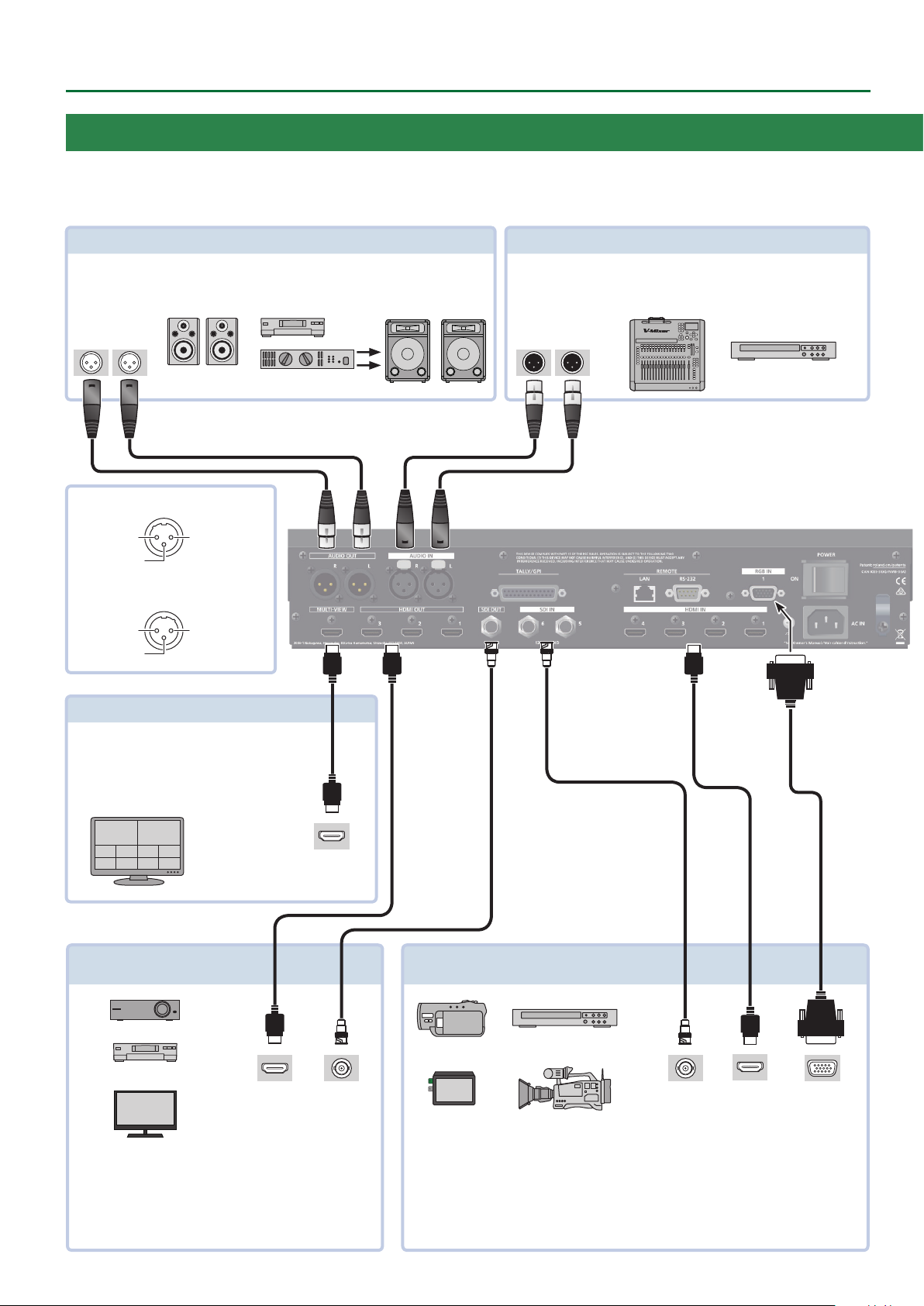
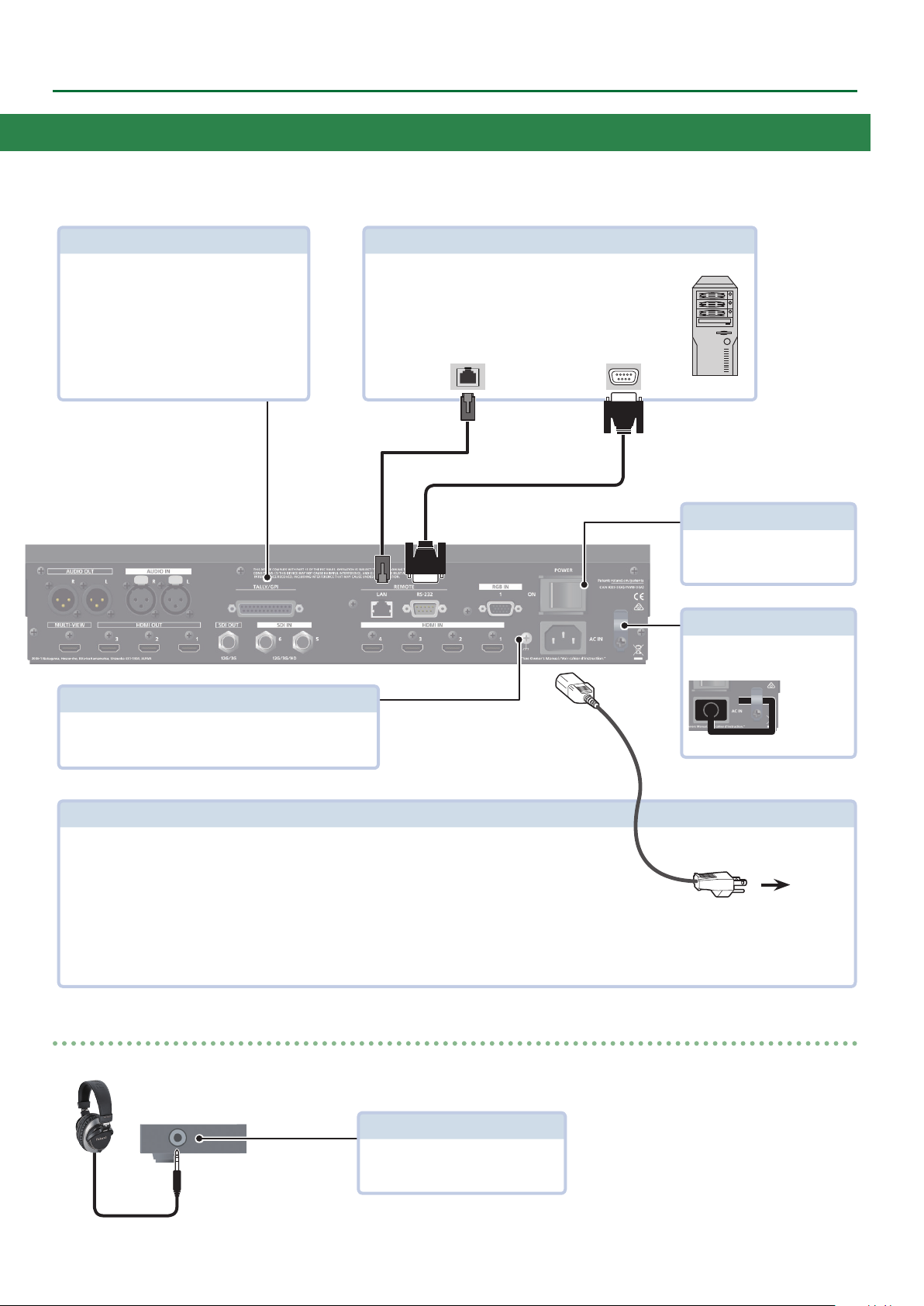
Rear Panel / Front Panel (Connecting Your Equipment)
* To prevent malfunction and equipment failure, always turn down the volume, and turn o all the units before making any connections.
* Be sure to use cables and adaptor plugs with the proper connectors matching those of the other devices you are using.
AUDIO OUT L, R connector
Output the results of audio mixing.
Connect an audio recorder, amplier, speakers, or other such equipment.
Audio input
connectors
Pin assignment of AUDIO IN connectors
2: HOT
3: COLD
Pin assignment of AUDIO OUT connectors
1: GND
3: COLD
1: GND
2: HOT
AUDIO IN L, R connector
Inputs the audio signals.
Connect an audio mixer, CD players, or other such audio equipment.
Audio output
connectors
MULTI-VIEW connector
Outputs an input/output video list (nal output,
preview output, and input channels 1–8) and menus.
Connect a multi-view monitor here.
* The multi-view output is xed at 1920 x 1080/60 Hz,
RGB, SDR, and HDCP 1.4.
HDMI
input connector
HDMI OUT 1–3 connectors /
SDI OUT connector
HDMI input
connector
Outputs the video/audio signals. Connect projectors, recording
equipment, and external displays.
SDI input
connector
RGB IN 1 connector / HDMI IN 1–4 connectors /
SDI IN 5, 6 connectors
SDI output
connector
Input video and audio. Connect video cameras, BD players or other video devices, or computers.
5 The input format is detected automatically.
5 You can use the menu to check the format of the video that is input to each channel, and
whether an HDCP signal is present.
* Use the menu to specify whether you will use the RGB IN 1 connector or the HDMI IN 1 connector.
HDMI output
connector
Analog RGB
output connector
5
Page 6
Panel Descriptions
TALLY/GPI connector
Connect devices provided with a tally-light feature
or with control-signal output functionality to this
connector.
* For details on the specications of the TALLY/GPI
connector, refer to p. 46.
LAN connector, RS-232 connector
5 You can use a web browser or terminal software to
remotely control this unit.
5 You can connect a computer equipped with an RS-232
connector, and remotely control this unit.
LAN
connector
RS-232
connector
[POWER] switch
Turns the power on/o.
Cord hook
Clamps the power cord to secure
it in place.
Ground terminal
Connect this to an external earth or ground if necessary.
AC IN connector
Connects the included power cord.
* Be sure to use the included power cord for connecting the power supply.
Front panel
PHONES jack (Stereo miniature type)
To AC Outlet
* The shape of the power cord’s plug
varies depending on the country.
Connect headphones.
6
Page 7
Panel Descriptions
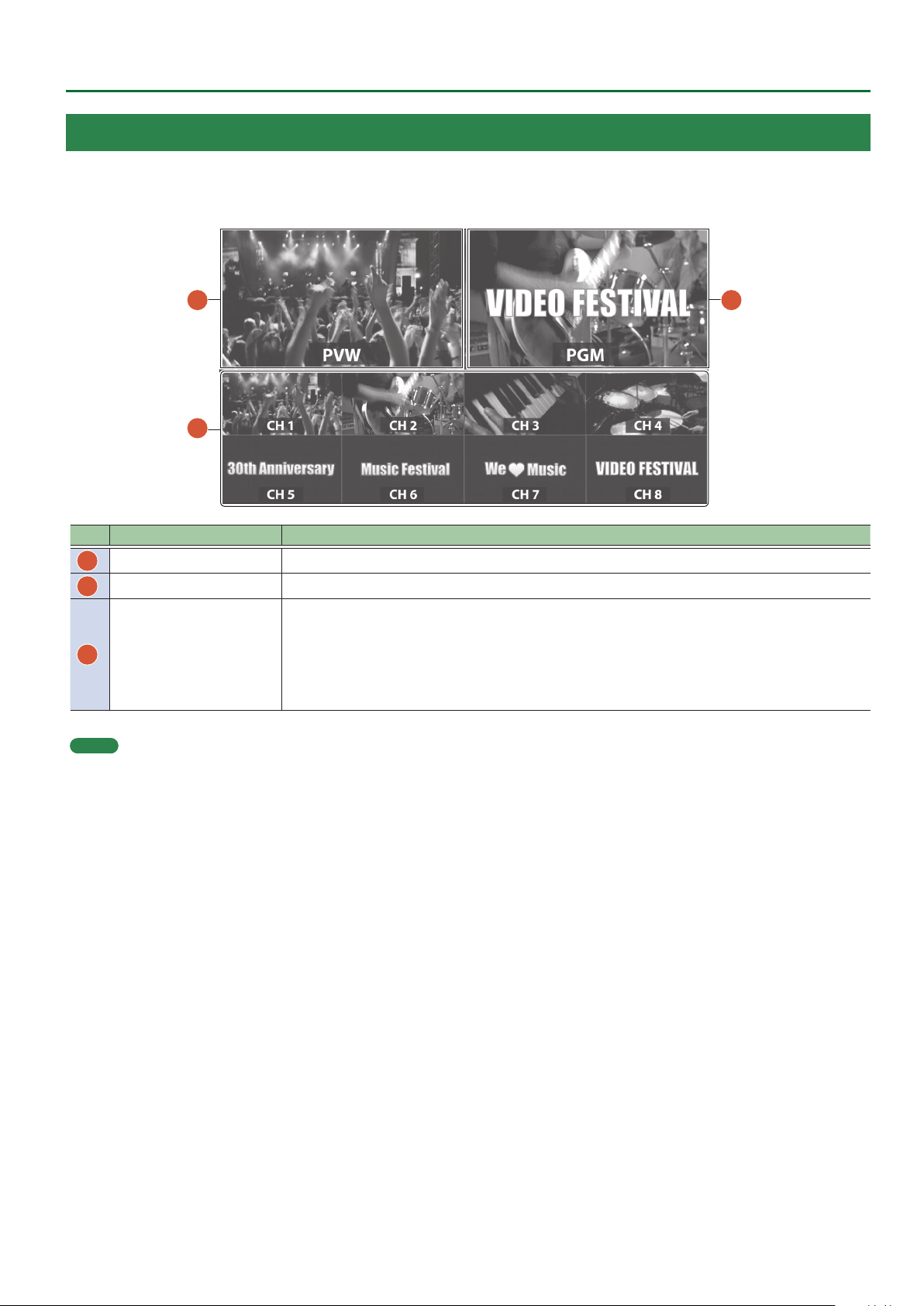
Multi-View Monitor Display
An input/output video list (nal output, preview output, and input channels 1–8) and menus are displayed on a multi-view monitor connected to
the MULTI-VIEW connector.
Pressing the [MENU] button displays the menu superimposed over the multi-view (p. 8).
1
3
2
No. Name Explanation
PVW (preview) section This displays the preset video (the video to be output next).
1
PGM (program) section This displays the nal output video.
2
This monitors the video input via channels 1–8.
A red border is displayed around the nal video output. A green border is displayed around the preset
CH 1–8 section
3
MEMO
You can change the label names displayed on the multi-view monitor.
Use the [MENU] button&“System”&“Output”&“MULTI-VIEW”&“Label,” then change the label name.
video (the video to be output next).
* Settings for scaling (p. 12) is not applied.
* Changing the channel assignments at the cross-point (p. 25) also changes the order of displayed
sources.
7
Page 8
Basic Operations
Turning the Power On/O
* Before turning the unit on/o, always be sure to turn the volume
down. Even with the volume turned down, you might hear some
sound when switching the unit on/o. However, this is normal and
does not indicate a malfunction.
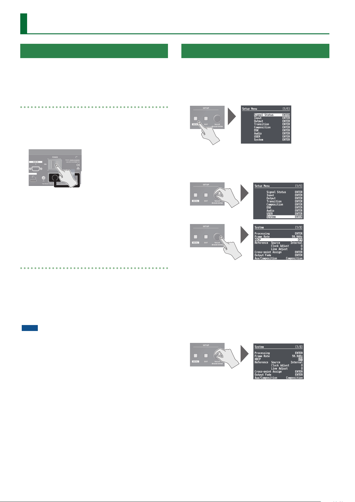
Turning the power on
1. Make sure all devices are turned o.
2. Turn on the [POWER] switch on the V-600UHD to
turn on the power.
3. Turn on the power to the source devices.
Turn on the power to video cameras or other source equipment
connected to input connectors on the V-600UHD.
Using the Menus
This explains how to display menus and make settings for video and
for the V-600UHD itself.
* Menus are shown only on the multi-view monitor connected to the
MULTI-VIEW connector (p. 7).
1. Press the [MENU] button to display the menu.
The [MENU] button lights up, the menu categories are displayed.
2. Turn the [VALUE] knob to select a category, and
press the [VALUE] knob to conrm.
4. Turn on the power to the output devices.
Turn on the power to projectors or other devices connected to
output connectors on the V-600UHD.
Turning the power o
1. Turn o the power in the sequence of rst the
output equipment, and then the sources.
2. Turn o the [POWER] switch on the V-600UHD to
turn o the power.
NOTE
5 Do not turn o the power while a message of “Executing...” is
shown on menu display area of the multi-view monitor. Your
settings may not be saved properly.
5 If you need to turn o the power completely, rst turn o the
V-600UHD, then unplug the power cord from the power outlet.
The menu for the selected category is displayed.
3. Turn the [VALUE] knob to select a menu item, then
press the [VALUE] knob to conrm.
The cursor moves to the setting value.
5 If the menu item is located at a deeper level, repeat step 3.
5 Pressing the [EXIT] button moves you back one level higher.
4. Turn the [VALUE] knob to change the value of the
setting.
5 By turning the [VALUE] knob while pressing it, you can change the
value more greatly.
5 Pressing and holding the [VALUE] knob returns the current menu
item you’re setting to its default value.
5. Press the [VALUE] knob to apply the setting.
The cursor returns to the menu item.
6. Press the [MENU] button to quit the menu.
8
Page 9
List of Supported Formats
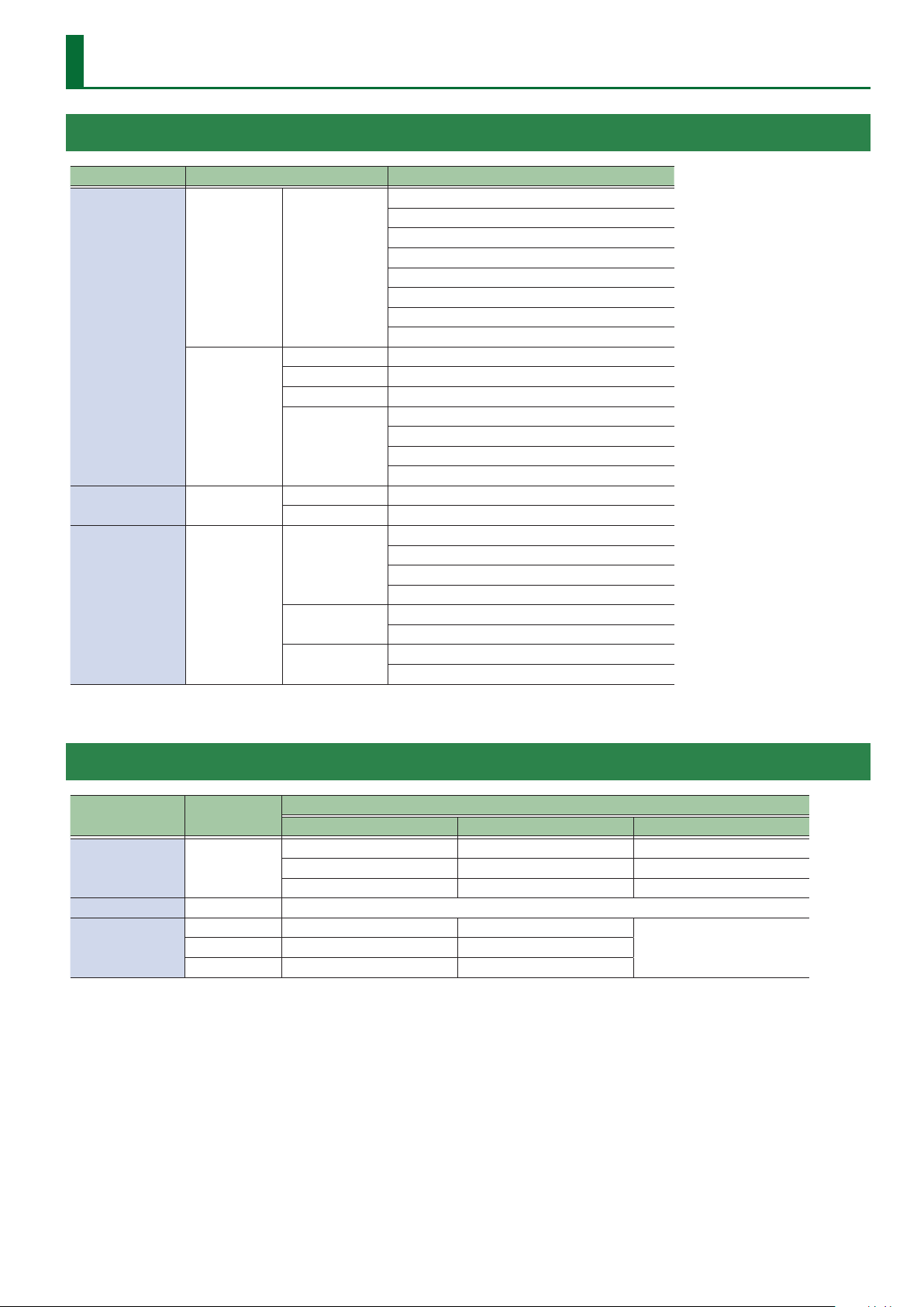
Input Formats
Input connector Supported formats Frame rate
1080/59.94i
1080/50i
1080/59.94p
Video CEA-861-F
HDMI IN
PC
RGB IN PC
SDI IN Video
VESA DMT 1600 x 1200/60 Hz (UXGA)
CEA-861-F 1920 x 1080/60 Hz (FHD)
VESA CVT 1920 x 1200/60 Hz (WUXGA, Reduced blanking)
CEA-861-F
VESA DMT 1600 x 1200/60 Hz (UXGA)
CEA-861-F 1920 x 1080/60 Hz (FHD)
SMPTE ST274
SMPTE ST2036
SMPTE ST2048
1080/50p
2160/59.94p (UHD 4K)
2160/50p (UHD 4K)
2160/59.94p (DCI 4K)
2160/50p (DCI 4K)
3840 x 2160/30 Hz (UHD 4K)
3840 x 2160/60 Hz (UHD 4K)
4096 x 2160/30 Hz (DCI 4K)
4096 x 2160/60 Hz (DCI 4K)
1080/59.94i
1080/50i
1080/59.94p
1080/50p
2160/59.94p (UHD 4K)
2160/50p (UHD 4K)
2160/59.94p (DCI 4K)
2160/50p (DCI 4K)
Output Formats
Output connector
HDMI OUT CEA-861-F
MULTI-VIEW CEA-861-F 1920 x 1080/60Hz (FHD)
SDI OUT
Supported
formats
SMPTE ST274 1080/59.94p 1080/50p
SMPTE ST2048 2160/59.94p (DCI 4K) 2160/50p (DCI 4K)
Video, When set at “59.94 Hz” Video, When set at “50 Hz”
1080/59.94p 1080/50p 1920 x 1080/60 Hz (FHD)
2160/59.94p (UHD 4K) 2160/50p (UHD 4K) 3840 x 2160/60 Hz (UHD 4K)
2160/59.94p (DCI 4K) 2160/50p (DCI 4K) 4096 x 2160/60 Hz (DCI 4K)
Output format, Flame rate
When set at PC format
N/ASMPTE ST2036 2160/59.94p (UHD 4K) 2160/50p (UHD 4K)
9
Page 10
Video Input/Output Settings
Setting the Output Format
You set the output format to match the equipment you connect to
the V-600UHD.
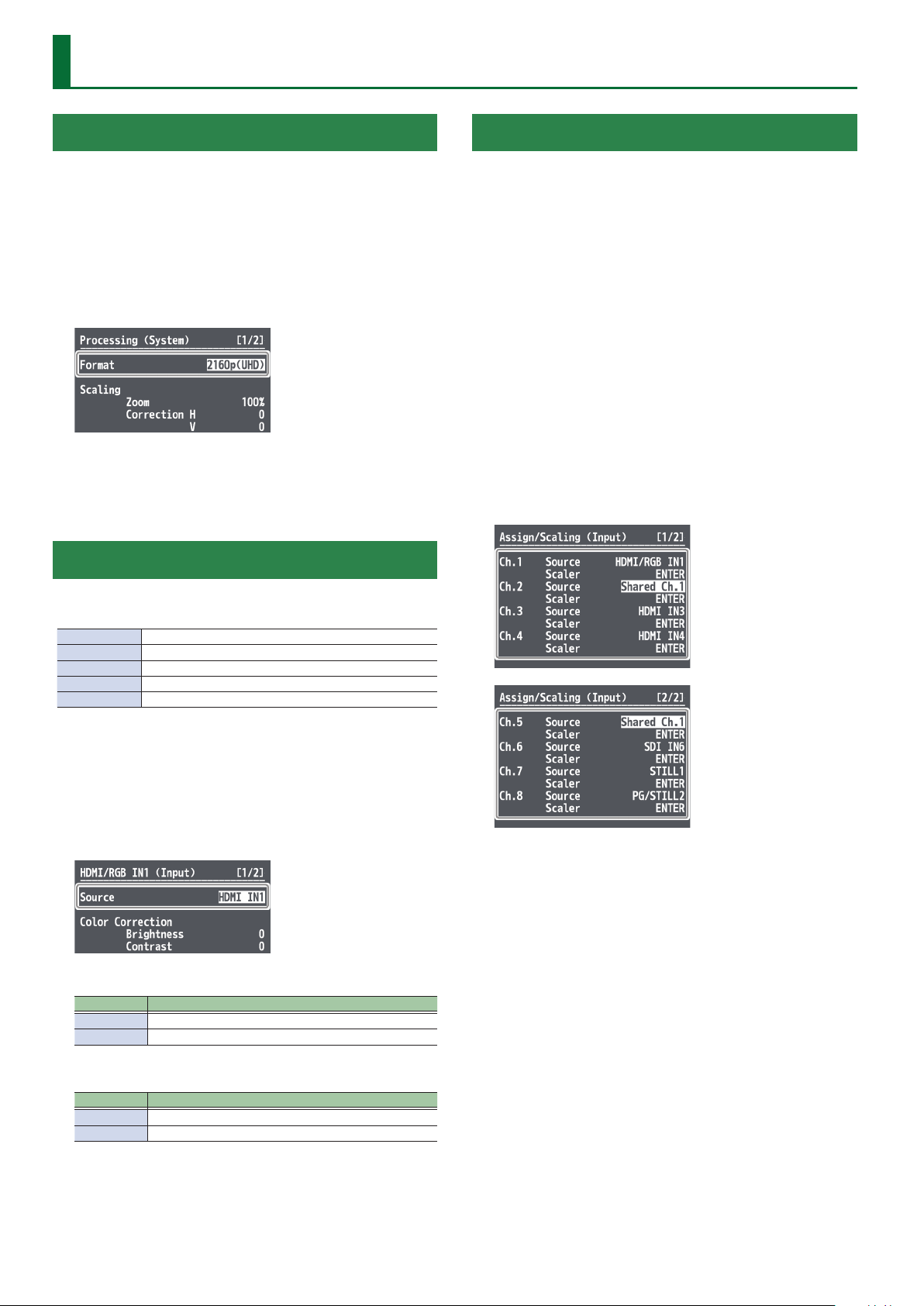
1. Select the [MENU] button&“System”&
“Processing,” and press the [VALUE] knob.
2. Select “Format,” press the [VALUE] knob, use the
[VALUE] knob to select the output format, and then
press the [VALUE] knob.
& Details on menu items: see p. 42.
3. Press the [MENU] button to quit the menu.
Assigning a Video Source to Input Channels
Sharing a Video Source
You can share separate video sources among channels 1–8.
Sharing a video source assigns a single video source to two or more
channels.
You can specify individual scaling settings for the shared video
sources.
* The following settings cannot be individually specied for shared
video sources.
5 Color Correction
5 Color Gamut
5 Dynamic Range
1. Select the [MENU] button&“Input”&
“Assign/Scaling,” and press the [VALUE] knob.
2. Select the “Source” of the channel whose video
source you want to share, and use the [VALUE]
knob to select the share-source channel.
For example, if you want to share the video source of channel 1,
select “Shared Ch.1.”
You can specify an assigned video source for each individual input
channel. You can assign the following video sources.
Channel 1 Video input via an HDMI IN1 connector or RGB IN1 connector
Channel 2–4 Video input via an HDMI IN2–4 connector
Channel 5–6 Video input via an SDI IN5–6 connector
Channel 7 Still1 picture
Channel 8 Pattern generator (background color) or still2 picture
1. Select the [MENU] button&“Input”&“HDMI/RGB
IN1” or “PG/STILL2,” and press the [VALUE] knob.
2. Select “Source,” press the [VALUE] knob, use the
[VALUE] knob to select the video source that you
want to assign, and then press the [VALUE] knob.
HDMI/RGB IN1
Value Explanation
HDMI IN1 This inputs video via an HDMI IN1 connector.
RGB IN1 This inputs video via an RGB IN1 connector.
3. Repeat step 2 as many times as needed.
4. Press the [MENU] button to quit the menu.
PG/STILL2
Value Explanation
PG This assigns a pattern generator
STILL2 This assigns a still2 image
3. Press the [MENU] button to quit the menu.
10
Page 11
Video Input/Output Settings
Assigning a Bus to an Output Connector
The V-600UHD has three internal buses (PGM, PVW, and AUX).
For each individual output connector, you can select which bus to
output.
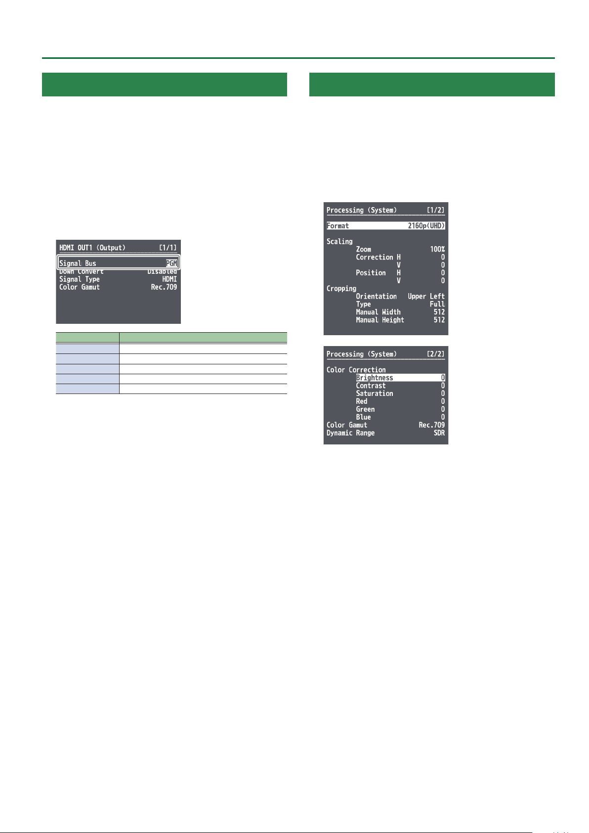
1. Select the [MENU] button&“Output” to select the
output connector whose bus assignment you want
to change, and press the [VALUE] knob.
2. Select “Signal Bus,” and use the [VALUE] knob to
select “PGM,” “PVW,” or “AUX,” and set the assigned
bus.
Menu item Signal Bus setting
HDMI OUT 1 PGM, PVW, AUX
HDMI OUT 2 PGM, PVW, AUX
HDMI OUT 3 PGM, PVW, AUX
SDI OUT PGM xed
MULTI-VIEW No bus selection
Adjusting Final Output Video
You adjust the nal video output to match the equipment receiving
output from the V-600UHD.
1. Select the [MENU] button&“System”&
“Processing,” and press the [VALUE] knob.
2. Select a menu item, then use the [VALUE] knob to
adjust the output video.
3. Press the [MENU] button to quit the menu.
& Details on menu items: see p. 42.
3. Press the [MENU] button to quit the menu.
11
Page 12
Video Input/Output Settings
Adjusting the Input Video
You can adjust the image quality and scaling of video input via
channels 1–8.
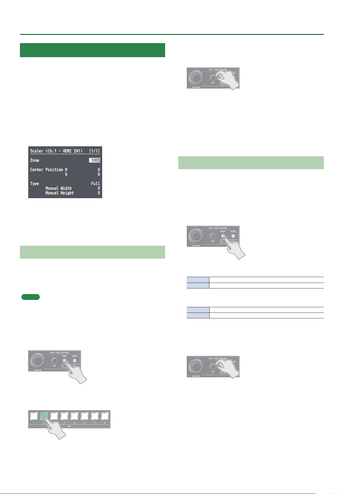
1. Select the [MENU] button&“Input”&
“Assign/Scaling,” and press the [VALUE] knob.
2. Select the Ch.1–8 “Scaler” and press the [VALUE]
knob.
3. Select a menu item, then use the [VALUE] knob to
adjust the input video.
& Details on menu items: see p. 29.
4. Press the [MENU] button to quit the menu.
3. Use the [POSITION] stick to adjust the display
position of the video. Also, use the [SIZE] knob to
enlarge or reduce the video.
The operation results are applied in the PVW section of the multiview monitor.
* The video in the CH 1–8 section of the multi-view monitor is not
updated.
* In the section that is specied as Shared Input, a frame is shown
around the region that is being magnied by ROI.
Adjusting the PinP Size
Operate the [POSITION] stick and the [SIZE] knob to adjust the
position and size of the PinP inset screen.
* This cannot be controlled if PinP is being applied to the nal
output video.
1. Press the [PinP1] button or [PinP2] button to select
the object of control.
Using ROI SCALING to Adjust the Input Video
You can use the ROI (Region of Interest) function to extract a desired
region from the input video.
You can operate the [POSITION] stick and the [SIZE] knob to adjust
the position and size of the video to be extracted.
MEMO
By making settings to share video sources between channels 1–8 (p.
10), you can extract up to eight regions from a single input video.
1. Press the [PinP1] button or the [PinP2] button
several times to make both buttons light magenta.
ROI (INPUT) is selected.
2. Press PST cross-point buttons [1]–[8] to select the
video that you want to control.
[PinP1] button
Lit green PinP1 window
Lit red Video shown in the PinP1 inset screen
[PinP2] button
Lit green PinP2 window
Lit red Video shown in the PinP2 inset screen
2. Use the [POSITION] stick to adjust the display
position of the video. Also, use the [SIZE] knob to
enlarge or reduce the video.
The operation results are applied in the PVW section of the multiview monitor.
12
Page 13
Inputting Copyright-protected (HDCP)
OFF
Video
To input copyright-protected (HDCP) video from a Blu-ray Disc player
or the like, follow the steps described below to change the “HDCP”
setting.
* The V-600UHD must be connected to an HDCP compatible display
for HDCP protected video to be connected.
What’s HDCP?
HDCP is copyright-protection technology that prevents unlawful
copying of content by encoding the path when sending digital
signals from a video playback device to a display monitor or
other display equipment.
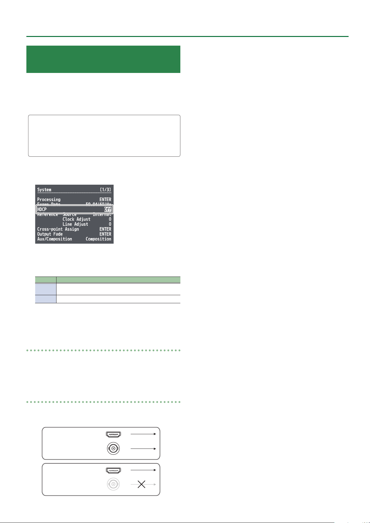
1. Select the [MENU] button&“System”&“HDCP,”
and press the [VALUE] knob.
Video Input/Output Settings
2. Use the [VALUE] knob to select “On,” and then press
the [VALUE] knob.
Value Explanation
On
O Copyright-protected (HDCP) video cannot be input.
Copyright-protected (HDCP) video can be input. HDCP is also
added to the video that is output.
3. Press the [MENU] button to quit the menu.
Checking HDCP-compatible equipment
When “HDCP” is set to “On,” you can use the [MENU] button& “Signal
Status” & “Input Ch.1–8” &“HDCP”& the Input menu to check the
status of HDCP compatibility of source equipment.
Output from Connectors
When “HDCP” is set to “On,” video is output only from the HDMI OUT
connectors.
HDMI OUT
ON
SDI OUT
HDMI OUT
SDI OUT
13
Page 14
Video Input/Output Settings
Operation of the HDCP indicator
Indicator HDCP Connection status
Lighted On
Flashing
Dark O —
An HDCP-compatible device is connected to the HDMI OUT
connector.
On A device that does not support HDCP is connected.
Video for which copy protection (HDCP) must be enabled is
O
being input from the HDMI IN connector.
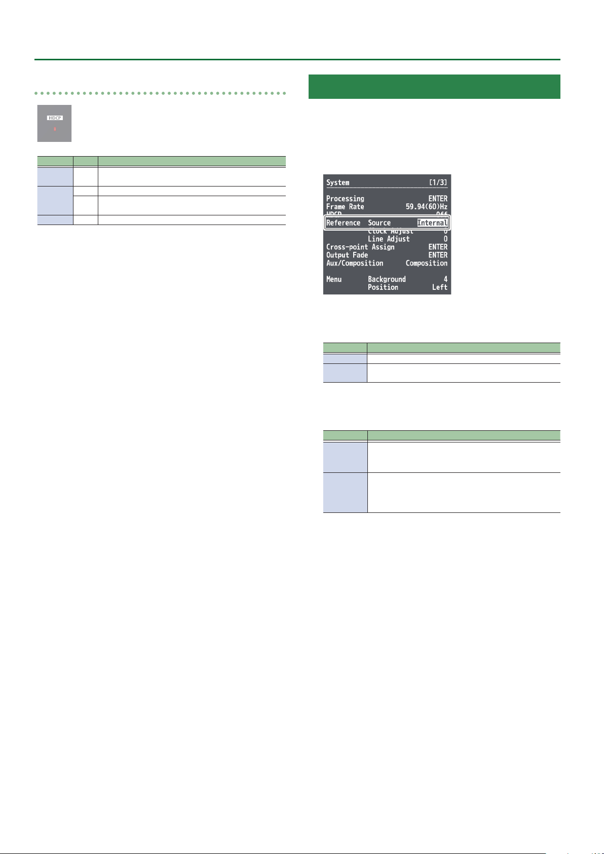
Specifying a Reference Clock
You can specify a clock to which operation of the V-600UHD is
referenced (a reference clock).
1. Select the [MENU] button&“System”&
“Reference Source,” and press the [VALUE] knob.
2. Use the [VALUE] knob to select the reference clock,
and then press the [VALUE] knob.
Value Explanation
Internal The V-600UHD’s internal clock is used as the reference clock.
SDI IN5
A signal input via an SDI IN5 connector is used as the reference
clock.
When set to “SD IN5,” adjust the following System menu items as
needed.
Value Explanation
This adjusts the phase horizontally.
Clock Adjust
Line Adjust
Adjust this when output is horizontally out of sync with the
operation of other devices using the same clock.
This adjusts the phase vertically.
Adjust this when output is vertically out of sync with or eldshifted from the operation of other devices using the same
clock.
3. Press the [MENU] button to quit the menu.
14
Page 15
Video Operations
Switching the Video
You can switch the output of video input into the V-600UHD.
Switching Using the Video Fader
The video in the PGM section always becomes the nal output. You
use the PST section to select and check the preset video (the video to
output next), then switch it.
1. Move the video fader all the way to one end or the
other.
2. Press one of the WIPE PATTERN [1]–[3] buttons or
the [MIX] button to select the transition eect.
The selected button lights up.
WIPE PATTERN [1]–[3] buttons
In this transition, the original video is broken into by the
next video.
* You can change the wipe pattern and wipe direction
(p. 32).
[MIX] button
The two pictures are blended together as the video is
switched.
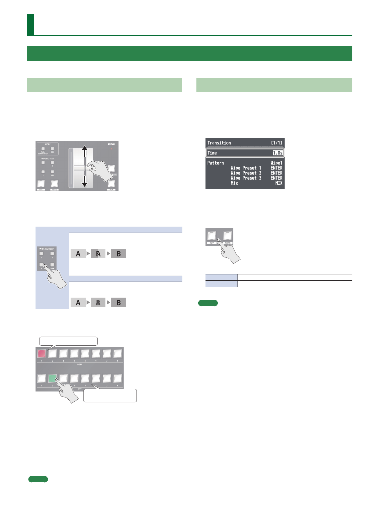
Using the [AUTO] or [CUT] Button to Switch Video
You can use the [AUTO] or [CUT] button to switch video
automatically, without using the video fader.
1. Select the [MENU] button&“Transition”&“Time,”
and use the [VALUE] knob to set the transition time.
2. Press the [MENU] button to quit the menu.
3. Press the [AUTO] or [CUT] button at the desired
timing for switching the video.
[CUT] button The picture switches instantly.
[AUTO] button The picture switches with a transition eect applied.
3. Press a cross-point [1]–[8] button in the PST section
to select the preset video (the video to output next).
Lighted in red: Final output video
Lighted in green: Preset video
(the video to be output next)
The preset video appears in the PVW section of the multi-view
monitor.
4. Move the video fader in the direction opposite to
the direction in step 1.
The output video is switched.
When the video has been switched completely, the lighted
buttons for the PGM position and PST position change places.
MEMO
Directly selecting the video channel at the PGM position of the
video currently being output switches the video with a cut,
regardless of any selection of a transition eect.
MEMO
When you use the [AUTO] or [CUT] button to switch video, the
actual output might come to dier from the position of the video
fader.
15
Page 16
Video Operations
Using Imported Still Images
You can take a still image imported from a USB ash drive and assign it to channel 7 or 8, then output it in the same way as video.
NOTE
Depending on the USB ash drive, recognition of the ash drive might take some time.
Importing a Still Image from a USB Flash Drive
This imports into the unit a still image saved on a USB ash drive.
Supported still-image formats and resolutions
Still-image le formats that can be imported are as follows.
Format Bitmap (.bmp), 24-bit, uncompressed
Resolution Maximum 4096×2160 pixels
File name
Importing a still image
* When you’re using a USB ash drive for the rst time, be sure to
format it on the V-600UHD (p. 25).
1. Save the still image in the root directory of the USB
ash drive.
2. Connect the USB ash drive containing the saved
still image to the USB MEMORY port.
3. Select the [MENU] button&“System”&
USB Memory/Still Image “STILL1 Load” or “STILL2
Load,” and press the [VALUE] knob.
8 single-byte alphanumeric characters
* Be sure to append the “.bmp” le extension.
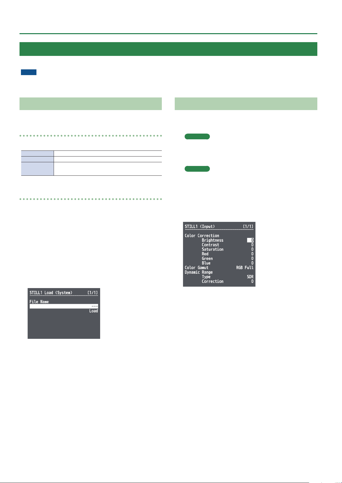
Assigning a Still Image to Channel 7 or 8
This takes a still image imported from a USB ash drive and assigns it to
channel 7 or 8.
Channel 7
1.
Select the [MENU] button&“System”&“HDCP,”
and press the [VALUE] knob.
Channel 8
Select the [MENU] button&“Input”&
“PG/STILL2”&specify “STILL2” as the source
assignment&press the [VALUE] knob.
2. Select a menu item, then use the [VALUE] knob to
make the detailed settings.
4. Use the [VALUE] knob to select the still image le
you want to import.
5. Select “Load,” and press the [ENTER] button.
The message “Are you sure?” appears.
If you want to cancel the operation, select “NO,” and press the
[VALUE] knob.
6. Select “YES,” and press the [VALUE] knob.
The still image is imported into the unit.
7. Press the [MENU] button to quit the menu.
& Details on menu items: see p. 30.
3. Press the [MENU] button to quit the menu.
16
Page 17

Applying a Fade to the Final Output Video (Output Fade)
This applies a fade to nal video output. This lets you make the nal
output fade to a monochrome picture (background color) or still
image at times when you want to suppress video output, such as
during intervals in a band performance. You can also stop (freeze) the
nal video output.
1. Select the [MENU] button&“System”&
“Output Fade,” and press the [VALUE] knob.
2. Select a menu item, then use the [VALUE] knob to
make the detailed settings.
Video Operations
& Details on menu items: see p. 41.
3. Press the [MENU] button to quit the menu.
Making the Final Video Output Fade Out/Fade In
* During the fade, the [OUTPUT FADE] button
ashes.
1. Press the [OUTPUT FADE] button to perform a fade-
out.
When the fade-out is complete, the [OUTPUT FADE] button lights
up.
2. To perform a fade-in, press the [OUTPUT FADE]
button again.
When the fade-in is complete, the [OUTPUT FADE] button goes
dark.
17
Page 18
Video Composition Operations
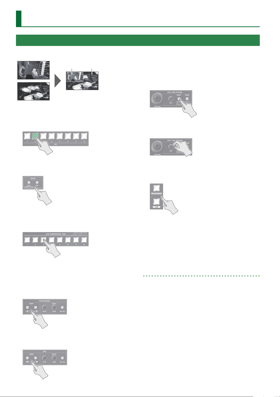
Compositing Using Picture-in-Picture (PinP)
This composites video in an inset screen onto a dierent background
video.
Background videoInset screen
1. Press a cross-point [1]–[8] button in the PGM
section to select the video you want to make the
background video.
2. Press the MODE [AUX/COMPOSITION] button or [DSK]
button to select the send-destination for the video.
The selected button lights up in green, and a preview of the
composition results is displayed in the PVW section of the multiview monitor.
At this stage, the nal output has not yet been changed.
5. Press the PinP/ROI SCALING [PinP1] or [PinP2]
button to select the object of control.
6. Use the [POSITION] stick and the [SIZE] knob to
adjust the position and size of the inset screen.
7. If the object of control is PinP1, press the
[COMPOSITION] button; if PinP2, press the [DSK]
button.
3. Press a cross-point [1]–[8] button in the AUX/
COMPOSITION - DSK section to select the video you
want to make the inset screen.
4. According to the button that you pressed in step
2, press one of the following buttons to turn video
compositing on (lit).
If you pressed the [AUX/COMPOSITION] button
Press the COMPOSITION PinP1 [1] or [2] button.
If you pressed the [DSK] button
Press the DSK PinP2 [1] or [2] button.
At this time, the PinP [1] or [2] button light up in red.
Pressing the [COMPOSITION] or [DSK] button a second time makes
the inset screen disappear.
8. To turn video compositing o, make the
[COMPOSITION] or [DSK] button go dark, and then
press the PinP [1] or [2] button.
Making detailed settings for the inset screen
For each of the COMPOSITION PinP1 [1] and [2] buttons and the DSK
PinP2 [1] and [2] buttons, you can make settings such as the position
and size of the inset screen and the border that is added to the inset
screen.
PinP1 [1], [2] buttons
Select the [MENU] button&“Composition”&for PinP1, select
“Position 1” or “Position 2.”
& Details on menu items: see p. 33.
PinP2 [1], [2] buttons
Select the [MENU] button&“DSK”&for PinP2, select “Position 1” or
“Position 2.”
18
& Details on menu items: see p. 35.
Page 19

Compositing Using Luminance Key/Chroma Key
This makes a portion of the video transparent and composites it onto a background video.
Video Composition Operations
Luminance Key
This takes video in which white or black areas are made transparent,
and composite it overlaid on a background picture.
Black or White
Chroma Key
This composites video shot against a blue or green background onto
a dierent background video.
Blue or Green
Compositing using key
1. Press a cross-point [1]–[8] button in the PGM
section to select the video you want to make the
inset screen.
2. Press the MODE [AUX/COMPOSITION] button or [DSK]
button to select the send-destination for the video.
3. Press a cross-point [1]–[8] button in the AUX/
COMPOSITION - DSK section to select the video to
overlay.
Setting the key type and extraction color
To change the key type and extraction color to match the video you
want to composite.
COMPOSITION
1.
Select the [MENU] button&“Composition”&
“Key1,” and press the [VALUE] knob.
DSK
Select the [MENU] button&“DSK”&“Key2,” and
press the [VALUE] knob.
2. Select “Type,” and use the [VALUE] knob to specify the
key type (extraction color) to use when compositing.
Value Explanation
Luminance White
Luminance Black
Chroma Blue This uses a color threshold to make blue transparent.
Chroma Green This uses a color threshold to make green transparent.
Chroma Manual
This uses a brightness threshold to make white
transparent.
This uses a brightness threshold to make black
transparent.
This uses a color threshold to make manual color
transparent.
4. According to the button that you pressed in step
2, press one of the following buttons to turn key
compositing on (lit).
If you pressed the [AUX/COMPOSITION] button
Press the COMPOSITION KEY1 [KEY ON] button.
If you pressed the [DSK] button
Press the DSK KEY2 [KEY ON] button.
The KEY1 [KEY ON] or KEY2 [KEY ON] button lights up in green,
and a preview of the composition results is displayed in the PVW
section of the multi-view monitor.
At this stage, the nal output has not yet been changed.
3. Press the [MENU] button to quit the menu.
19
Page 20

Video Composition Operations
5. Turn the KEY [LEVEL] or [GAIN] knob (KEY1 or KEY2)
to adjust the degree of eect applied.
KEY [LEVEL] knob
This adjusts the degree of extraction (transparency) for the key.
KEY [GAIN] knob
This adjusts the degree of edge blur (semi-transmissive region) for
the key.
6. If the object of control is KEY1, press the
[COMPOSITION] button; if KEY2, press the [DSK]
button.
The video you selected in steps 1 and 3 is composited and output.
At this time, the KEY1 or KEY2 [KEY ON] button light up in red.
Pressing the [AUTO] or [CUT] button a second time makes the
overlaid video disappear.
MEMO
5 When you combine PinP (p. 18) with the compositing results
from luminance or chroma key, the superimposed video becomes
the inset screen.
You can also use the [POSITION] stick and the [SIZE] knob to adjust
the display position and size of the overlaid video.
Making advanced settings for chroma key
When the key type is “Chroma Manual,” you can use the Key menu to
ne-tune the key color.
Menu item Explanation
Hue Center This adjusts the center position for hue of key color.
Width This adjusts the hue width (range) of key color.
Saturation Center This adjusts the center position for saturation of key color.
Width This adjusts the saturation width of key color.
20
Page 21

Audio Operations
Adjusting the Input/Output Volume
Here’s how to adjust the audio volume (Level) that is being input to
or output from the V-600UHD.
1. Use [MENU] button&“Audio”&“Input”/“Output”
to select the object of volume adjustment, and then
press the [VALUE] knob.
2. Select “Level,” and use the [VALUE] knob to adjust
the volume.
3. Press the [MENU] button to quit the menu.
Muting the Input Audio
Here’s how to silence a specic audio input (mute function).
1. Use [MENU] button& “Audio”&“Input” to select
the object for muting, and press the [VALUE] knob.
Interlinking Audio Output to Video Switching (Audio Follow)
Here’s how to make the specied audio be automatically output or
muted in linkage with video switching.
1. Use [MENU] button&“Audio”&“Input” to select
the object for audio follow, and press the [VALUE]
knob.
2. Select “Follow,” and use the [VALUE] knob to turn
the setting On/O.
Value Explanation
This enables the Audio Follow feature.
On
Muting is performed automatically when video on another channel
is output.
O This disables the Audio Follow feature.
3. Press the [MENU] button to quit the menu.
2. Select “Mute,” and use the [VALUE] knob to set this
to “On.”
3. Press the [MENU] button to quit the menu.
Matching the Timing of the Input/Output Audio with the Video
1. Use [MENU] button&“Audio”&“Input”/“Output”
to select the object of timing adjustment, and then
press the [VALUE] knob.
2. Select “Delay,” and use the [VALUE] knob to specify
the time by which the audio is delayed.
Applying Audio Follow to AUDIO IN
1. Select the [MENU] button&“Audio”&“Input”&
“AUDIO IN,” and press the [VALUE] knob.
2. Select “Follow,” and use the [VALUE] knob to select
the input to which audio follow will be applied.
Value Explanation
HDMI/RGB IN1
HDMI IN2–4
SDI IN5, 6
O This assigns no video channel to Audio Follow.
This sets the video channel to interlink with input audio
using Audio Follow.
Audio from AUDIO IN is muted out for video channels other
than what you specied.
3. Press the [MENU] button to quit the menu.
3. Press the [MENU] button to quit the menu.
21
Page 22

Audio Operations
Mixing Input Audio with HDMI Video or SDI Video
The SDI connectors of the V-600UHD support 16 channels of embedded audio. The HDMI connectors support two channels of embedded audio.
The MAIN bus of the V-600UHD’s audio mixer has a 16-channel structure.
Selecting the audio input channels to mix
You can select the MAIN bus channels into which the HDMI IN, SDI IN,
and AUDIO IN audio will be mixed.
1. Use [MENU] button&“Audio”&“Input” to select
HDMI IN 1–4, SDI IN5–6, or AUDIO IN, and press the
[VALUE] knob.
2. Select “Mix Ch.1/2”–“Mix Ch.15/16,” and use the
[VALUE] knob to turn the setting On/O.
The SDI IN audio can be switched on/o by the “Mix Ch.1-16”
settings.
Mixing input audio into the AUX bus
The V-600UHD has a two-channel AUX bus, and you can specify
whether input audio is mixed into the AUX bus.
* The rst two channels of SDI IN audio can be mixed into the AUX
bus.
1. Use [MENU] button&“Audio”&“Input” to select
HDMI IN 1–4, SDI IN5–6, or AUDIO IN, and press the
[VALUE] knob.
2. Select “Aux Send,” and use the [VALUE] knob to
specify the volume that is sent to the aux bus.
3. Press the [MENU] button to quit the menu.
3. Press the [MENU] button to quit the menu.
Selecting the audio source that is output
For each output connector, you can select either a specied channel
of the MAIN bus or the AUX bus as the source that will be output.
* For SDI OUT audio, you can select either the entire MAIN bus or the
AUX bus.
1. Select the [MENU] button&“Audio”&“Output”&
“Source,” and press the [VALUE] knob.
2. Select the connector for which you want to make
settings, and use the [VALUE] knob to specify the
channel.
3. Press the [MENU] button to quit the menu.
22
Page 23

Other Operations
Saving/Recalling Settings (Memory)
You can save video settings, the state of the operation panel, and other current settings in memory and call them up for use when needed.
The V-600UHD has 8 internal banks for saving settings in memory.
You can save settings in 8 memories in each bank, letting you use up to 64 memories for saving.
About the Last Memory Function
When you use the Last Memory function, the current settings are automatically saved in memory 1 of bank 1 when you exit a menu or recall a
memory. To use the Last Memory function, go to the System menu and set “Auto Memory” to “ON.”
Saving a memory
NOTE
5 When the System menu item “Memory Protect” is set to “On,”
settings cannot be saved to a memory.
5 The following settings are not saved in memory.
– The state of the operating panel’s [OUTPUT FADE] button
– The items of the Output, USER, and System menus
1. Press the [STORE] button (button lit) to enable
saving settings to a memory.
2. Press the [BANK] button (button lit), then press the
MEMORY button for the bank number where you
want to save the settings.
Button illumination color when selecting memories
Lit light blue Current blue
Lit blue Memory in which current settings are saved
Blinking blue
Unlit Memory in which no settings are saved
The [STORE] button blinks, the current settings are saved, and
then the [STORE] button goes dark.
MEMO
If you don’t want to change the save-destination bank, steps 2–3
are not required.
Memory in which current settings are saved (current
memory has not been edited)
Recalling a memory
1. Press the [BANK] button (button lit), then press
the MEMORY button for the bank number whose
settings you want to recall.
The bank changes.
Button illumination color when selecting banks
Lit green Bank in which current memory is saved
Blinking green Currently selected bank
Lit blue Bank in which a memory is saved
Unlit Bank in which no memory is saved
3. Press the [BANK] button to make the button go
dark.
4. Press the MEMORY button for the number whose
setting you want to save.
2. Press the [BANK] button to make the button go
dark.
3. Press the MEMORY button for the number whose
setting you want to recall.
MEMO
If you don’t want to change the recall-source bank, steps 1–2 are
not required.
23
Page 24

Other Operations
Saving the Unit’s Settings to File on a USB Flash Drive
You can group together the values in the unit’s memories (1-1 through 8-8) into a single le and save it to a USB ash drive connected to the USB
MEMORY port. You can access the saved le on the USB ash drive and load it into the unit for use when needed.
* When you’re using a USB ash drive for the rst time, be sure to format it on the V-600UHD (p. 25).
* Depending on the USB ash drive, recognition of the ash drive might take some time.
Choose save new
1. Select the [MENU] button&“System”&select the
USB Memory “Parameter Save As,” and press the
[VALUE] knob.
2. Specify the le name.
The extension of the le name is “.prm.”
3. Select “Save,” and press the [VALUE] knob.
The message “Are you sure?” appears.
If you want to cancel the operation, select “NO,” and press the
[VALUE] knob.
Recalling
This recalls the settings in the unit’s memories (1-1 through 8-8) that
have been saved on a USB ash drive. Recalling settings overwrites
any values in the unit’s memories.
1. Select the [MENU] button&“System”&select
the USB Memory “Parameter Load,” and press the
[VALUE] knob.
2. Select the le that you want to recall, select “Load,”
and press the [VALUE] knob.
The message “Are you sure?” appears.
If you want to cancel the operation, select “NO,” and press the
[VALUE] knob.
3. Select “YES,” and press the [VALUE] knob.
The settings are recalled, and the values in the unit’s memories are
overwritten.
4. Press the [MENU] button to quit the menu.
Deleting a le on a USB ash drive
4. Select “YES,” and press the [VALUE] knob.
The le (*.prm) is newly saved on the USB ash drive.
5. Press the [MENU] button to quit the menu.
MEMO
Still images (p. 16) are not saved in the le (*.prm).
Saving by Overwriting
1. Select the [MENU] button&“System”&select
the USB Memory “Parameter Save,” and press the
[VALUE] knob.
2. Select the le that you want to overwrite, select
“Save,” and press the [VALUE] knob.
The message “Are you sure?” appears.
If you want to cancel the operation, select “NO,” and press the
[VALUE] knob.
3. Select “YES,” and press the [VALUE] knob.
The le is saved by overwriting.
1. Select the [MENU] button&“System”&select
the USB Memory “Parameter Delete,” and press the
[VALUE] knob.
2. Select the le that you want to delete, select
“Delete,” and press the [VALUE] knob.
The message “Are you sure?” appears.
If you want to cancel the operation, select “NO,” and press the
[VALUE] knob.
3. Select “YES,” and press the [VALUE] knob.
The settings are deleted from the USB ash drive.
4. Press the [MENU] button to quit the menu.
4. Press the [MENU] button to quit the menu.
24
Page 25

Other Operations
Formatting USB Flash Drives
When you’re using a USB ash drive for the rst time, it must rst be
formatted on the V-600UHD.
NOTE
5 The V-600UHD does not recognize unformatted USB ash drives.
5 Operation has been tested for commonly available USB ash
drives, but operation of all USB ash drives is not assured.
Depending on the manufacturer and type of the USB ash drive,
correct operation may not be possible.
5 Performing formatting causes all data already saved on the USB
ash drive to be deleted. If the ash drive contains necessary data,
back it up onto a computer or elsewhere before formatting the
drive.
5 Depending on the USB ash drive, recognition of the ash drive
might take some time.
1. Select the [MENU] button&“System”&for USB
Memory, select “Format,” and press the [VALUE]
knob.
Changing Cross-point Assignments
You can change the channels assigned to the cross-point [1]–[8]
buttons.
1. Select the [MENU] button&“System”&
“Cross-point Assign,” and press the [VALUE] knob.
2. Select cross-point cross point (from XPT1 to 8),
then use the [VALUE] knob to specify the channel
number (Ch. 1 to 8) to assign to the cross point.
* To assign no channel, specify “None.”
3. Press the [MENU] button to quit the menu.
The message “Are you sure?” appears.
If you want to cancel the operation, select “NO,” and press the
[VALUE] knob.
2. Select “YES,” and press the [VALUE] knob.
Formatting of the USB ash drive is carried out.
3. Press the [MENU] button to quit the menu.
Returning Settings to the Factory-default State (Factory Reset)
You can return the values of settings on the V-600UHD to their
factory defaults.
NOTE
Executing a factory reset causes all values that have been set, settings
saved in memories (p. 23), and still images saved in the unit to be
lost.
1. Select the [MENU] button&“System”&
“Factoy Reset,” and press the [VALUE] knob.
The message “Are you sure?” appears.
If you want to cancel the operation, select “NO,” and press the
[VALUE] knob.
2. Select “YES,” and press the [VALUE] knob.
A factory reset is executed.
3. Press the [MENU] button to quit the menu.
25
Page 26
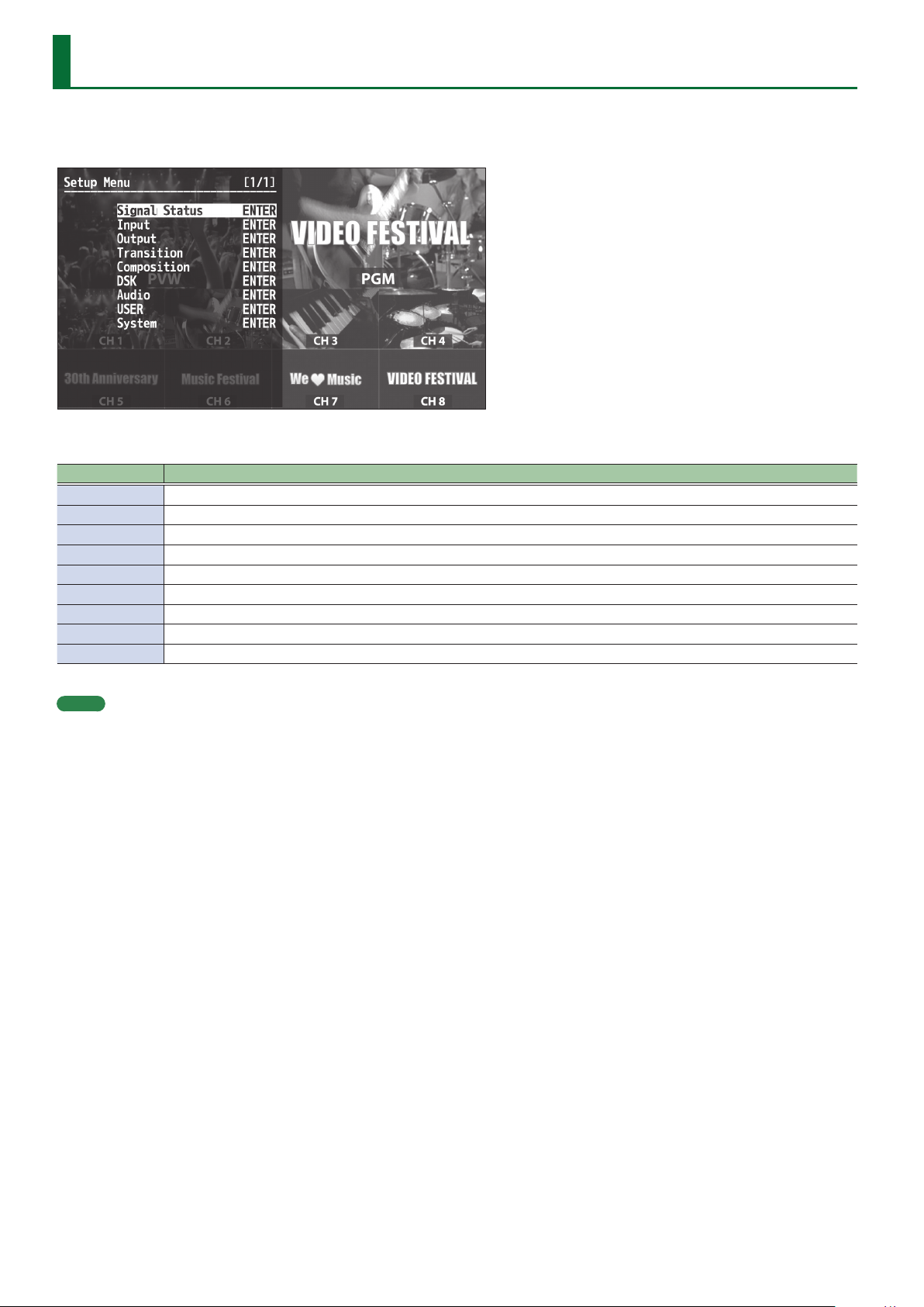
Menu List
Press the [MENU] button to call up the menu items. The menu will appear on the multi-view monitor connected to the V-600UHD.
* Menus are shown only on the multi-view monitor connected to the HDMI OUT connector.
The menu categories are displayed at rst. Choose the menu category whose setting you want to change.
Category Explanation
Signal Status This is for showing input signal status.
Input This is for input setup like source assign etc.
Output This is for output setup.
Transition This is for transition setup.
Composition This is for Picture in Picture setup, luminance and chroma key setup.
DSK This is for Picture in Picture setup, luminance and chroma key setup.
Audio This is for audio setup.
USER This is for setup of user function.
System This is for system setup of the V-600UHD.
MEMO
5 When a setting value has menu items that let you make more-detailed settings, “ENTER” is displayed at the top of the screen. Press the [VALUE]
knob to go down a level.
5 To execute an operation, press the [VALUE] knob.
5 You can change a setting value rapidly by holding down the [VALUE] button and turning.
5 Long-press the [VALUE] knob returns the currently selected setting to its default value.
26
Page 27
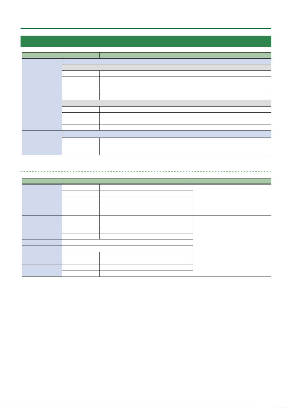
Signal Status
Menu item Displayed value Explanation
This displayes input status. Pressing the [VALUE] knob displays the detailed information.
9 Ch.1–4
No Signal No signal
Video Format: 1080iRATE, 1080pRATE, 2160p(UHD)RATE, 2160p(DCI)RATE, Unsupported
Input Ch.1–8
Output
RESOLUTION
Shared Ch.1–8 This enables sharing of the video source on the other channel.
9 Ch.5–8
No Signal No signal
RESOLUTION
Shared Ch.1–8 This enables sharing of the video source on the other channel.
This display output status. Pressing the [VALUE] knob displays the detailed information.
RESOLUTION
PC Format: WxH@RATE, Unsupported
RATE is displayed only in integer part (example: 59.94 0 59).
Video Format: 1080iRATE, 1080pRATE, 2160p(UHD)RATE, 2160p(DCI)RATE, Unsupported
RATE is displayed only in integer part (example: 59.940 59).
Video Format: 1080pRATE, 2160p(UHD)RATE, 2160p(DCI)RATE
PC Format: WxH@RATE
RATE is displayed only in integer part (example: 59.94 0 59).
Menu List
Input Ch.1–Ch.8
Menu item Displayed value Explanation
Source
Resolution
Frame Rate 30, 50, 59.94, 60, -
HDCP 1.x, 2.2, None, -
Color Gamut
Dynamic Range
[VALUE]
0
Input Ch.1 HDMI IN1, RGB IN1, Shared Ch.2–8
Input Ch.2–4 HDMI IN2–4, Shared Ch.1–8
Input Ch.5–6 SDI IN5–6, Shared Ch.1–8
Input Ch.7 STILL1, Shared Ch.1–8
Input Ch.8 PG, STILL2 , Shared Ch.1–7
Input Ch.1–4
Input Ch.5–6 1080i, 1080p, 2160p(UHD), 2160p(DCI), No Signal
Input Ch.7–8 Maximum 4096x2160, No Image
Input Ch.1–6 Rec.709, Rec.2020, RGB Full, RGB Limited, -
Input Ch.7–8 SDR
Input Ch.1–6 SDR, HDR PQ, HDR HLG, -
Input Ch.7–8 RGB Full, RGB Limited
1600x1200–4096x2160, 1080i, 1080p,
2160p(UHD), 2160p(DCI), No Signal
This part displays the video source to assign
to the channel.
This part displays the current input format.
27
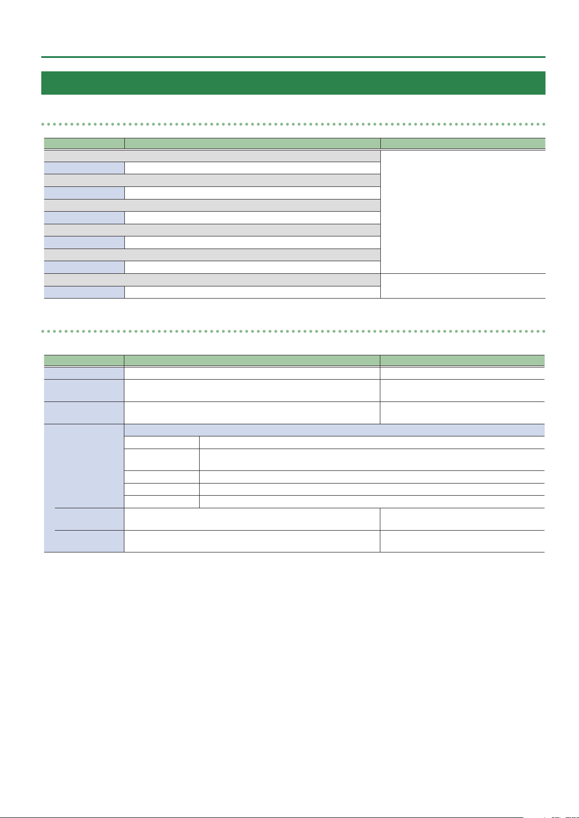
Page 28

Menu List
Output
Menu item Displayed value Explanation
Format 1920x1080, 3840x2160, 4096x2160, 1080p, 2160p(UHD), 2160p(DCI)
Frame Rate 1080p, 2160p(UHD), 2160p(DCI), 50, 59.94, 60
HDCP O, On
Color Gamut Rec.709, Rec.2020, RGB Full, RGB Limited
Dynamic Range SDR, HDR PQ, HDR HLG
9 HDMI1
BUS PGM, PVW, AUX
Down Convert Disabled, Enabled
9 HDMI2
BUS PGM, PVW, AUX
Down Convert Disabled, Enabled
9 HDMI3
BUS PGM, PVW, AUX
Down Convert Disabled, Enabled
9 SDI
BUS PGM, -
Down Convert Disabled, Enabled
0
[VALUE]
This part displays the current output format.
This part displays output bus settings and
down convert settings.
28
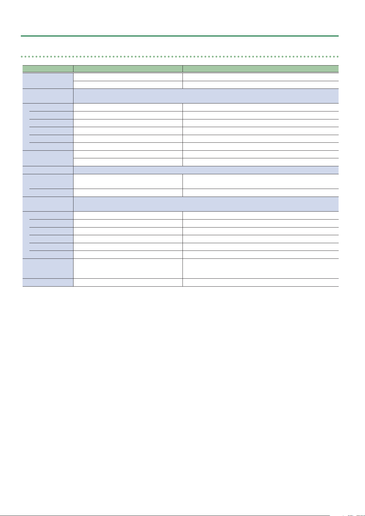
Page 29
Input
Menu List
Assign/Scaling
Menu item Value (Bold: default) Explanation
9 Ch.1
Source HDMI/RGB IN1, Shared Ch.2–8
9 Ch.2–4
Source HDMI IN2–4, Shared Ch.1–8
9 Ch.5–6
Source SDI IN5–6, Shared Ch.1–8
9 Ch.7
Source STILL1, Shared Ch.1–8
9 Ch.8
Source PG/STILL2 , Shared Ch.1–7
9 Ch.1–8
Scaler ENTER
Scaler
You use the following items to make settings for scaling.
Menu item Value (Bold: default) Explanation
Zoom 10–100–1000% This adjusts the zoom ratio.
Center Position H -4096–0–+4096
V -2160–0–+2160
Type
Manual Width
(*1)
Manual Height
(*1)
0
[VALUE]
[VALUE]
0
This sets the video source to assign to the
channel.
default value of Ch.2–6
Ch.2: HDMI IN2
Ch.3: HDMI IN3
Ch.4: HDMI IN4
Ch.5: SDI IN5
Ch.6: SDI IN6
Pressing the [VALUE] knob displays the
detailed settings menu.
This adjusts the display position in the
horizontal direction.
This adjusts the display position in the vertical
direction.
This sets the scaling type.
Full The input image will be displayed fully on output screen. The aspect ratio will be changed.
Letterbox
Crop The input image will be displayed fully on the output screen. The aspect ratio will be maintained.
DotByDot Scaling will not be executed.
Manual This performs scaling according to the “Manual Width” and “Manual Height” settings.
-4000–0–+4000 This adjusts the horizontal size.
-4000–0–+4000 This adjusts the vertical size.
The entirety of the input image will be displayed on output screen. The aspect ratio will be
maintained.
(*1) Available when Type is set to “Manual.”
29
Page 30
Menu List
HDMI/RGB IN1, HDMI IN2–4, SDI IN5–6, STILL1, PG/STILL2
Menu item Value (Bold: default) Explanation
Source
Color Correction
Brightness -64–0–+63 This adjusts the brightness.
Contrast -64–0–+63 This adjusts the contrast.
Saturation -64–0–+63 This adjusts the color saturation.
Red -64–0–+63 This adjusts the red level.
Green -64–0–+63 This adjusts the green level.
Blue -64–0–+63 This adjusts the blue level.
Color Gamut
Dynamic Range
Type SDR, HDR PQ, HDR HLG, Auto
Correction -64–0–+63 This adjust dynamic range.
Sampling
Auto Sampling Execute This executes automatic settings for sampling.
Frequency -8–0–+8 This adjusts the sampling frequency.
Phase -8–0–+8 This adjusts the sampling phase.
Gain -20–0–+20 This adjusts the sampling gain.
Position H -16–0–+16 This adjusts the horizontal start position of sampling.
V -16–0–+16 This adjusts the vertical start position of sampling.
Pattern (*1)
Motion (*1) Disabled, Slow, Medium, Fast Species the scroll speed of the test pattern.
HDMI IN1, RGB IN1 This sets the input connector assigned to channel 1.
PG, STILL2 This assigns a pattern generator (Test Pattern) or still image to channel 8.
You use the following items to perform color correction.
* Not available when source is “PG.”
Rec.709, Rec.2020, RGB Full, RGB Limited, Auto This part select color gamut or color spaces of Input Ch.1–6.
RGB Full, RGB Limited This part select color gamut or color spaces of Input Ch.7–8.
You use the following items for make settings for sampling.
* Available when Source is set to “RGB IN1.”
Colorbar75%, Colorbar100%, Ramp, Step,
Hatch, Frame, Circle, Red, Green, Blue, White,
Black
[VALUE]
0
This part select dynamic range of Input Ch.1–6.
* Input Ch.7–Ch.8 are xed at SDR.
Species the test pattern.
(*1) Available when Source is set to “PG” in Ch.8.
30
Page 31
Output
Menu List
HDMI OUT1–3
Menu item Value (Bold: default) Explanation
Signal Bus PGM, PVW, AUX (*1) This sets the bus to be sent to HDMI OUT 1–3 connectors.
Down Convert Disabled, Enabled
Signal Type HDMI, DVI-D
Color Gamut Rec.709, Rec.2020, RGB Full, RGB Limited
(*1) HDMI OUT 1 : PGM, HDMI OUT 2: PVW, HDMI OUT 3: AUX
SDI OUT
Menu item Value (Bold: default) Explanation
Signal Bus PGM / Disabled
Down Convert Disabled, Enabled
3G-SDI Mapping Level A, Level B
0
0
[VALUE]
[VALUE]
This species whether down convert from 4K to FHD is enabled or
disabled.
* Available when Output Format is set to “2160p(UHD)” or
“3840x2160.”
This sets the output mode for HDMI output.
* This can be selected if OUTPUT Format is “1920x1080.”
This part select color gamut or color spaces.
* “RGB Full” and “RGB Limited” can be selected if OUTPUT Format
is “1920x1080,” “3840x2160,” or “4096x2160,” and Signal Type is
“HDMI.”
This part displays the output status of SDI Output.
This is xed at PGM in the case of video resolution, and xed at
Disabled in the case of PC resolution.
This species whether down convert from 4K to FHD is enabled or
disabled.
* Available when Output Format is set to “2160p(UHD).”
This displays the mapping structure for 3G-SDI output.
* Available when Output Format is set to “1080p.”
* This can be selected if OUTPUT Format is “2160p(UHD)” and Down
Convert is “Enabled.”
MULTI-VIEW
Menu item Value (Bold: default) Explanation
Layout
PGM
Label Pressing the [VALUE] knob displays the following label entry screen.
PGM PGM
PVW PVW
XPT1 CH.1
XPT2 CH.2
XPT3 CH.3
XPT4 CH.4
XPT5 CH.5
XPT6 CH.6
XPT7 CH.7
XPT8 CH.8
[VALUE]
0
Upper Left, Upper Right, Lower Left, Lower Right This switches the position of PGM in Multi-View display.
To edit the label name, move the cursor to the label name and press
the [VALUE] knob.
To conrm the label name, move the cursor to “Execute” and press
the [VALUE] knob.
31
Page 32

Menu List
Transition
Menu item Value (Bold: default) Explanation
Time 0.0–1.0–4.0s This sets the transition time.
This sets the transition eect.
Pattern Wipe1, Wipe2, Wipe3, Mix
Wipe Preset 1 ENTER
Wipe Preset 2 ENTER
Wipe Preset 3 ENTER
Mix FAM, NAM, MIX This species the transition pattern assigned to the [MIX] button.
* The WIPE PATTERN [1]–[3] buttons and the [MIX] button are “Wipe
Pattern” shortcut buttons.
This displays the Detailed Settings menu for the WIPE PATTERN [1]–[3]
buttons.
Wipe Preset 1–3
Menu item Value (Bold: default) Explanation
Pattern
Direction Normal, Reverse, N/R This sets the wipe direction.
Curve Linear, Slow In, Cosine, Slow Out This sets the wipe curve for video transition.
Position H (*2) -100.0–0–+100.0% This sets the horizontal position of start video transition.
V (*3) -100.0–0–+100.0% This sets the vertical position of start video transition.
Aspect ratio (*4) 1:1, 4:3, 3:2, 16:9 This sets aspect ratio of video transition.
Correction H (*2) -100.0–0–+100.0% This adjusts the horizontal position of start video transition.
V (*3) -100.0–0–+100.0% This adjusts the vertical position of start video transition.
Border You use the following items to adjust the border settings.
Width 0–10pixel This adjusts the border width.
Color H 0–359deg. This sets the hue of border color.
S 0–100% This sets the saturation of border color.
V 0–50–100% This sets the value of border color.
(*1) Wipe Preset 1: Horizontal, Wipe Preset 2: Vertical, Wipe Preset 3: Box
(*2) Not valid when Pattern is set to “Horizontal,” “Vertical,” or “Vertical Open.”
(*3) Not valid when Pattern is set to “Horizontal,” “Vertical,” or “Horizontal Open.”
(*4) Not valid when Pattern is set to “Horizontal,” “Vertical,” “Horizontal Open,” or “Vertical Open.”
[VALUE]
0
Horizontal, Vertical, Horizontal Open, Vertical
Open, Upper Left, Upper Right, Lower Left, Lower
Right, Box (*1)
This sets the wipe pattern.
32
Page 33

Menu List
Composition
Menu item Value (Bold: default) Explanation
Status PGM O, On
PVW O, On
Source Channel XPT1–XPT3–XPT8 This sets the source channel of PinP1 and KEY1.
Type
PinP1 Position 1 ENTER This displays the Detailed Settings menu for the PinP1 Position 1.
Position 2 ENTER This displays the Detailed Settings menu for the PinP1 Position 2.
Key1 ENTER This displays the Detailed Settings menu for the KEY1.
None, PinP1-1, PinP1-2, Key1,
PinP1-1+Key1, PinP1-2+Key1
This species whether the result of PinP1/KEY1 compositing is sent to
the nal output (On) or is not sent (O).
This species whether the result of PinP1/KEY1 compositing is sent to
preview (On) or is not sent (O).
This sets the type of PinP1 and KEY1.
PinP1 Position 1–2
Menu item Value (Bold: default) Explanation
View Use the following items to adjust the video displayed in the inset screen.
Size 10.0–100.0–1000.0% This sets the zoom ratio.
Position H -4096–0–+4095 This adjusts the display position in the horizontal direction.
V -2160–0–+2159 This adjusts the display position in the vertical direction.
Window Use the following items to make the settings for the inset screen.
Size 10.0–30.0–100.0% This adjusts the zoom ratio.
Aspect ratio 1:1, 4:3, 16:9, System This sets the aspect ratio of the inset screen.
Corrction H -100.0–0–+100.0% This adjust the horizontal size of the inset screen.
V -100.0–0–+100.0% This adjust the vertical size of the inset screen.
Position H -4096–+4096 (*1) This adjusts the display position in the horizontal direction.
V -2160–-270–+2160 This adjusts the display position in the vertical direction.
Type Border, Shadow This sets the type of border for the inset screen.
Border
Width 0–10–40pixel This sets the border width.
Color H 0–359deg. This sets the hue of border color.
S 0–100% This sets the saturation of border color.
V 0–50–100% This sets the value of border color.
Shadow * Available when Type is set to “Shadow.”
Position H -10.0–0–+10.0% This sets the horizontal ratio of shadow to inset screen.
V -10.0–0–+10.0% This sets the vertical ratio of shadow to inset screen.
Level 0–50–100% This set darkness for shadow.
[VALUE]
0
Use the following items to adjust the border.
* Available when Type is set to “Border.”
(*1) Position 1: -480, Position 2: 480
33
Page 34

Menu List
Key1
Menu item Value (Bold: default) Explanation
Type
Level 0–32–255 This adjusts the amount of extraction.
Gain 0–255 This adjusts the amount of edge blur.
Chroma Manual * Available when Type is set to “Chroma Manual.”
Shadow
[VALUE]
0
This sets the key type (extraction color) to use when compositing.
Luminance White This uses a brightness threshold to make white transparent.
Luminance Black This uses a brightness threshold to make black transparent.
Chroma Blue This uses a color threshold to make blue transparent.
Chroma Green This uses a color threshold to make green transparent.
Chroma Manual This uses a color threshold to make manual color transparent.
Hue Center 0–120–359deg. This adjusts the center position for hue of key color.
Width 0–10–359deg. This adjusts the hue width (range) of key color.
Saturation Center 0–90–100% This adjusts the center position for saturation of key color.
Width 0–10–100% This adjusts the saturation width of key color.
Position H 0–32pixel This part set shadow height for key eect.
Level 0–255 This part set shadow darkness for key eect.
34
Page 35

Menu List
DSK
Menu item Value (Bold: default) Explanation
Status PGM O, On
PVW O, On
Source Channel XPT1–XPT8 This sets the source channel of PinP2 and KEY2.
Type
PinP2 Position 1 ENTER This displays the Detailed Settings menu for the PinP2 Position 1.
Position 2 ENTER This displays the Detailed Settings menu for the PinP2 Position 2.
Key2 ENTER This displays the Detailed Settings menu for the KEY2.
None, PinP2-1, PinP2-2, Key2,
PinP2-1+Key2, PinP2-2+Key2
This species whether the result of PinP2/KEY2 compositing is sent to
the nal output (On) or is not sent (O).
This species whether the result of PinP2/KEY2 compositing is sent to
preview (On) or is not sent (O).
This sets the type of PinP2 and KEY2.
PinP2 Position 1–2
Menu item Value (Bold: default) Explanation
View Use the following items to adjust the video displayed in the inset screen.
Size 10.0–100.0–1000.0% This sets the zoom ratio.
Position H -4096–0–+4095 This adjusts the display position in the horizontal direction.
V -2160–0–+2159 This adjusts the display position in the vertical direction.
Window Use the following items to make the settings for the inset screen.
Size 10.0–30.0–100.0% This adjusts the zoom ratio.
Aspect ratio 1:1, 4:3, 16:9, System This sets the aspect ratio of the inset screen.
Corrction H -100.0–0–+100.0% This adjust the horizontal size of the inset screen.
V -100.0–0–+100.0% This adjust the vertical size of the inset screen.
Position H -4096–+4096 (*1) This adjusts the display position in the horizontal direction.
V -2160–0–+2160 This adjusts the display position in the vertical direction.
Type Border, Shadow This sets the type of border for the inset screen.
Border
Width 0–10–40pixel This sets the border width.
Color H 0–359deg. This sets the hue of border color.
S 0–100% This sets the saturation of border color.
V 0–50–100% This sets the value of border color.
Shadow * Available when Type is set to “Shadow.”
Position H -10.0–0–+10.0% This sets the horizontal ratio of shadow to inset screen.
V -10.0–0–+10.0% This sets the vertical ratio of shadow to inset screen.
Level 0–50–100% This set darkness for shadow.
[VALUE]
0
Use the following items to adjust the border.
* Available when Type is set to “Border.”
(*1) Position 1: -480, Position 2: 480
35
Page 36

Menu List
Key2
Menu item Value (Bold: default) Explanation
Type
Level 0–32–255 This adjusts the amount of extraction.
Gain 0–255 This adjusts the amount of edge blur.
Chroma Manual * Available when Type is set to “Chroma Manual.”
Shadow
[VALUE]
0
This sets the key type (extraction color) to use when compositing.
Luminance White This uses a brightness threshold to make white transparent.
Luminance Black This uses a brightness threshold to make black transparent.
Chroma Blue This uses a color threshold to make blue transparent.
Chroma Green This uses a color threshold to make green transparent.
Chroma Manual This uses a color threshold to make manual color transparent.
Hue Center 0–120–359deg. This adjusts the center position for hue of key color.
Width 0–10–359deg. This adjusts the hue width (range) of key color.
Saturation Center 0–90–100% This adjusts the center position for saturation of key color.
Width 0–10–100% This adjusts the saturation width of key color.
Position H 0–32pixel This part set shadow height for key eect.
Level 0–255 This part set shadow darkness for key eect.
36
Page 37

Audio
Menu List
Input: HDMI IN1–4
Menu item Value (Bold: default) Explanation
Delay 0–500ms This adjusts the delay time for input audio (the frame value is also shown).
Mute O, On
Follow O, On
Level -INF–0–+10dB This adjusts the send level to MAIN bus.
Aux Send -INF–0–+10dB This adjusts the send level to AUX bus.
Mix Ch.1/2 O, On This switches the sending input audio to Mix Ch.1/2 on or o.
Mix Ch.3/4 O, On This switches the sending input audio to Mix Ch.3/4 on or o.
Mix Ch.5/6 O, On This switches the sending input audio to Mix Ch.5/6 on or o.
Mix Ch.7/8 O, On This switches the sending input audio to Mix Ch.7/8 on or o.
Mix Ch.9/10 O, On This switches the sending input audio to Mix Ch.9/10 on or o.
Mix Ch.11/12 O, On This switches the sending input audio to Mix Ch.11/12 on or o.
Mix Ch.13/14 O, On This switches the sending input audio to Mix Ch.13/14 on or o.
Mix Ch.15/16 O, On This switches the sending input audio to Mix Ch.15/16 on or o.
Input: SDI IN5–6
Menu item Value (Bold: default) Explanation
Delay 0–500ms This adjusts the delay time for input audio (the frame value is also shown).
Mute O, On
Follow O, On
Level -INF–0–+10dB This adjusts the sned level to MAIN bus.
Aux Send -INF–0–+10dB This adjusts the sned level to AUX bus.
Mix Ch.1-16 O, On This switches the sending input audio to Mix Ch.1–16 on or o.
0
0
[VALUE]
[VALUE]
This sets the Mute feature on or o.
Input audio for which this is set to “On” is silenced.
This switches the Audio Follow feature on or o.
Video channels for which this is set to “On” are automatically muted when
video on another channel is output.
This sets the Mute feature on or o.
Input audio for which this is set to “On” is silenced.
This switches the Audio Follow feature on or o.
Video channels for which this is set to “On” are automatically muted when
video on another channel is output.
Input: AUDIO IN
Menu item Value (Bold: default) Explanation
Delay 0–500ms This adjusts the delay time for input audio (the frame value is also shown).
Mute O, On
Follow
Level -INF–0–+10dB This adjusts the send level to MAIN bus.
Aux Send -INF–0–+10dB This adjusts the send level to AUX bus.
Mix Ch.1/2 O, On This switches the sending input audio to Mix Ch.1/2 on or o.
Mix Ch.3/4 O, On This switches the sending input audio to Mix Ch.3/4 on or o.
Mix Ch.5/6 O, On This switches the sending input audio to Mix Ch.5/6 on or o.
Mix Ch.7/8 O, On This switches the sending input audio to Mix Ch.7/8 on or o.
Mix Ch.9/10 O, On This switches the sending input audio to Mix Ch.9/10 on or o.
Mix Ch.11/12 O, On This switches the sending input audio to Mix Ch.11/12 on or o.
Mix Ch.13/14 O, On This switches the sending input audio to Mix Ch.13/14 on or o.
Mix Ch.15/16 O, On This switches the sending input audio to Mix Ch.15/16 on or o.
[VALUE]
0
O, HDMI/RGB IN1, HDMI IN2–4,
SDI IN5–6
This sets the Mute feature on or o.
Input audio for which this is set to “On” is silenced.
This sets the video channel to interlink with input audio using Audio Follow.
Audio from AUDIO IN is muted out for video channels other than what you
specied.
When this is set to “O,” no video channels using Audio Follow are assigned.
37
Page 38

Menu List
Input: Test Tone
Menu item Value (Bold: default) Explanation
Test Tone O, L:1K+R:2K This sets the test tone.
Level -INF–-20–+10dB This adjusts the send level to MAIN bus.
Aux Send -INF–-20–+10dB This adjusts the send level to AUX bus.
Mix Ch.1/2 O, On This switches the sending test tone to Mix Ch.1/2 on or o.
Mix Ch.3/4 O, On This switches the sending test tone to Mix Ch.3/4 on or o.
Mix Ch.5/6 O, On This switches the sending test tone to Mix Ch.5/6 on or o.
Mix Ch.7/8 O, On This switches the sending test tone to Mix Ch.7/8 on or o.
Mix Ch.9/10 O, On This switches the sending test tone to Mix Ch.9/10 on or o.
Mix Ch.11/12 O, On This switches the sending test tone to Mix Ch.11/12 on or o.
Mix Ch.13/14 O, On This switches the sending test tone to Mix Ch.13/14 on or o.
Mix Ch.15/16 O, On This switches the sending test tone to Mix Ch.15/16 on or o.
Output: Level/Delay
Menu item Value (Bold: default) Explanation
Main
Delay 0–500ms
Level -INF–0–+10dB This adjusts the volume level for MAIN bus.
Aux
Delay 0–500ms This adjusts the delay time for AUX bus (the frame value is also shown).
Level -INF–0–+10dB This adjusts the volume level for AUX bus.
AUDIO OUT
Level -INF–0–+10dB This adjusts the volume level for AUDIO OUT connectors.
PHONES
Level -INF–0–+10dB This adjusts the volume level for PHONES connectors.
OUTPUT Knob
Assign
[VALUE]
0
[VALUE]
0
This adjusts the delay time for MAIN bus (the frame value is also
shown).
Main, AUDIO OUT, PHONES This sets assign of [OUTPUT] knob for controlling volume adjust.
38
Page 39

Menu List
Output: Source
Menu item Value (Bold: default) Explanation
SDI OUT Ch.1-16, AUX This part select embedded audio bus via SDI out.
HDMI OUT1
HDMI OUT2
HDMI OUT3
MULTI-VIEW
AUDIO OUT /
PHONES
[VALUE]
0
Ch.1/2, Ch.3/4, Ch.5/6, Ch.7/8, Ch.9/10, Ch.11/12,
Ch.13/14, Ch.15/16, AUX
Ch.1/2, Ch.3/4, Ch.5/6, Ch.7/8, Ch.9/10, Ch.11/12,
Ch.13/14, Ch.15/16, AUX
Ch.1/2, Ch.3/4, Ch.5/6, Ch.7/8, Ch.9/10, Ch.11/12,
Ch.13/14, Ch.15/16, AUX
Ch.1/2, Ch.3/4, Ch.5/6, Ch.7/8, Ch.9/10, Ch.11/12,
Ch.13/14, Ch.15/16, AUX
Ch.1/2, Ch.3/4, Ch.5/6, Ch.7/8, Ch.9/10, Ch.11/12,
Ch.13/14, Ch.15/16, AUX
This part select embedded audio bus via HDMI out1.
This part select embedded audio bus via HDMI out2.
This part select embedded audio bus via HDMI out3.
This part select embedded audio bus via Multi-viw port.
This part select audio bus via XLR audio out / Phones.
39
Page 40

Menu List
USER
Menu item Value (Bold: default) Explanation
9 USER1
This sets the functions assigned to the USER [1] button.
Assign
LED Color Red, Green, Blue, Cyan, Magenta, Yellow This part set LED color of USER [1] button.
Mute Group Setup ENTER This displays detailed setup menu of mute group.
9 USER2
Assign
LED Color Red, Green, Blue, Cyan, Magenta, Yellow This part set LED color of USER [2] button.
Mute Group Setup ENTER This displays detailed setup menu of mute group.
None No function is assigned.
Follow SW This switches the Audio Follow feature on or o.
Mute Group This switches the Mute feature on or o globally for all audio assigned to a group.
This sets the functions assigned to the USER [2] button.
None No function is assigned.
Follow SW This switches the Audio Follow feature on or o.
Mute Group This switches the Mute feature on or o globally for all audio assigned to a group.
Mute Group Setup
Menu item Value (Bold: default) Explanation
HDMI IN1-4,
SDI IN5-6,
AUDIO IN
0
O, On
[VALUE]
This species whether each item is included in the USER 1–2 mute
group.
40
Page 41

Menu List
System
Menu item Value (Bold: default) Explanation
Processing ENTER This displays detailed setup menu of processing.
This sets the frame rate.
Frame Rate 50, 59.94Hz
HDCP O, On This turns on/o the HDCP mode.
Reference This sets the reference clock of the V-600UHD.
Internal The V-600UHD’s internal clock is used as the reference clock.
Source
Clock Adjust -4096–0–+4096
Line Adjust -2160–0–+2160
Cross-point Assign ENTER This displays detailed setup menu of channel assign to cross-points.
Output Fade ENTER This displays detailed setup menu of output fade.
Aux/Composition Composition, Aux This sets which function to use, AUX or Composition.
Memory Protect O, On
Menu Here you can make menu-related settings.
Background 0–4–7 This adjust the transparency of the menu background.
Position Left, Right This switches the position of menu display.
Auto Memory O, On Setting this to “On” enables last memory feature.
USB Memory You use the following items to work with a USB ash drive.
Parameter Load ENTER This displays the screen to select a le to load.
Save ENTER This displays the screen to select a le to save.
Save As ENTER This displays the screen to edit the le name.
Delete ENTER This displays the screen to select a le to delete.
Still Image
STILL1 Load
STILL2 Load ENTER This displays the screen to select a le to load for still image 2.
Format Execute This executes formatting of a connected USB ash drive.
RS-232 O, On This turns valid/invalid of remote control from an external RS-232 device.
Baudrate 9600, 38400 bps This sets the communication speed (bps) of the RS-232 connector.
GPI ENTER This displays detailed setup menu of GPI.
LAN Control ENTER This displays detailed setup menu of LAN control.
LED Dimmer 0–7 This adjusts the brightness of the top panel LEDs.
Fader Calibration ENTER This calibrates the video fader.
RGB IN1 Calibration ENTER This calibrates the RGB IN 1.
Factory Reset Execute This returns the unit to its factory defaults.
Version This displays the version of the system program.
SDI IN5
ENTER This displays the screen to select a le to load for still image 1.
If OUTPUT Format is “1920x1080,” “3840x2160,” or “4096x2160,” this is
xed at 60 Hz.
A signal input via one of the SDI IN5 connectors is used as the reference
clock.
This adjusts the phase horizontally.
Adjust this when output is horizontally out of sync with the operation of
other devices using the same clock.
This adjusts the phase vertically.
Adjust this when output is vertically out of sync with or eld-shifted from
the operation of other devices using the same clock.
When this is set to “On,” the memories are protected, and settings cannot
be saved to them.
41
Page 42
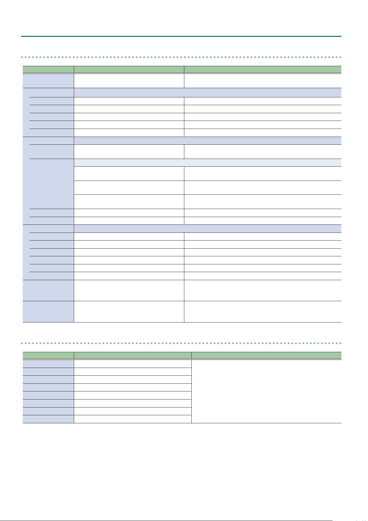
Menu List
Processing
Menu item Value (Bold: default) Explanation
Format
Scaling You use the following items to make settings for scaling.
Zoom 10–100–1000% This adjusts the zoom ratio.
Correction H -4000–0–+4000 This adjusts the horizontal zoom size.
V -4000–0–+4000 This adjusts the vertical zoom size.
Position H -4096–0–+4096 This adjusts the display position in the horizontal direction.
V -2160–0–+2160 This adjusts the display position in the vertical direction.
Cropping You use the following items to make settings for cropping.
Orientation
Type
Manual Width 0–512–4096 This adjusts the horizontal size.
Manual Height 0–512–2160 This adjusts the vertical size.
Color Correction You use the following items to perform color correction.
Brightness -64–0–+63 This adjusts the brightness.
Contrast -64–0–+63 This adjusts the contrast.
Saturation -64–0–+63 This adjusts the color saturation.
Red -64–0–+63 This adjusts the red level.
Green -64–0–+63 This adjusts the green level.
Blue -64–0–+63 This adjusts the blue level.
Color Gamut Rec.709, Rec.2020
Dynamic Range SDR, HDR PQ, HDR HLG
0
[VALUE]
1080p, 2160p(UHD), 2160p(DCI), 1920x1080,
3840x2160, 4096x2160
Upper Left, Upper Right, Lower Left, Lower
Right, Center
This sets the orientation of cropping.
Full
4:3, 5:4, 16:9
Manual
This part select V-600UHD’s output (system) format.
This sets the orientation of cropping.
When the “Zoom” value is “100%,” the entirety of the image is shown
on the output screen.
The image will be cropped according to the selected aspect ratio. If
the Zoom value is 100%, the image will be letterboxed.
The image will be cropped according to the “Manual Width” and
“Manual Height” settings.
This part select output (system) color gamut.
This can be selected if OUTPUT Format is “1080p,” “2160p (UHD),” or
“2160p (DCI).”
This part select output (system) dynamic range.
This can be selected if OUTPUT Format is “1080p,” “2160p (UHD),” or
“2160p (DCI).”
Cross-point Assign
Menu item Value (Bold: default) Explanation
XPT1 Ch.1–8, None
XPT2 Ch.1–2–8, None
XPT3 Ch.1–3–8, None
XPT4 Ch.1–4–8, None
XPT5 Ch.1–5–8, None
XPT6 Ch.1–6–8, None
XPT7 Ch.1–7–8, None
XPT8 Ch.1–8, None
0
[VALUE]
This sets the input channel to be assigned to Cross-point [1]–[8]
buttons.
42
Page 43
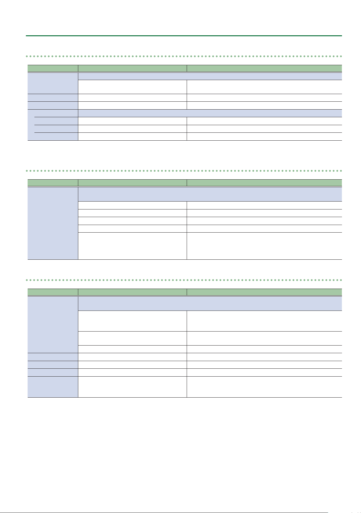
Menu List
Output Fade
Menu item Value (Bold: default) Explanation
Mode
Time 0–0.5–10.0s This sets the fade time.
Curve Linear, Slow In, Cosine, Slow Out This sets the fade curve for fade to background.
Color Setting You use the following items to set the background color.
Red 0–16–255 This sets the red level.
Green 0–16–255 This sets the green level.
Blue 0–16–255 This sets the blue level.
GPI
Menu item Value (Bold: default) Explanation
GPI1–8
0
[VALUE]
[VALUE]
0
This displays the operation mode of the [OUTPUT FADE] button.
Fade to Background
This sets the function assigned to the GPI channel.
* The GPI trigger is xed at the trailing edge (low: On). For details, refer to “Inputting a Control Signal” (p. 46).
None No function is assigned.
PGM XPT1–8 This switches the nal output video.
PST XPT1–8 This switches the preset video (the video to be output next).
Memory Load1-1–8 This loads a memory (Bank 1 only).
DSK SRC Sel1–8
This makes the nal video output fade to a monochrome picture
(background color).
During DSK compositing, this switches the channel of the overlaid
logo or image.
* When a control signal is input from an external source, the assigned
function is executed.
LAN Control
Menu item Value (Bold: default) Explanation
Congure
IP Address (*1) 192.168.2.254 This sets the IP address.
Subnet Mask (*1) 255.255.255.0 This sets the subnet mask.
MAC Address This displays the MAC address.
Remote Control URL http://192.168.2.254:8080/
(*1) This can be specied manually if Congure is set to “Manually.”
0
[VALUE]
Selects how settings are made for the IP address and subnet mask.
* Changed settings are applied at next start-up.
DHCP server functionality is enabled.
DHCP Server
DHCP Client
Manually The IP address and subnet mask are specied manually.
The information needed for connecting to the network is assigned
automatically by this unit to the computers that are on the LAN.
The IP address and other information needed for connecting to the
network is obtained automatically from the DHCP server of the LAN.
Shows the URL for starting the WebRCS web application in your web
browser.
* The URL is not shown if a network connection is not established.
43
Page 44

LAN/RS-232 Command Reference
V-600UHD support two types of remote-interface communication: LAN and RS-232.
Using the CONTROL port (LAN) or RS-232 connector to send specic commands to the V-600UHD from a controlling device lets you operate the
V-600UHD remotely.
LAN Interface
This uses the LAN port on the V-600UHD.
You use Telnet to operate the V-600UHD remotely over a LAN
(TCP/IP protocol).
Communication standards
Port LAN port
Protocol TCP
Port number 8023
Setting the IP address of the V-60HD
The method of setting the IP address depends on the Congure
setting.
If the Congure setting is “Manually,” use the following procedure
to make the setting.
1. Select the [MENU] button&“System”&
“LAN Control,” and press the [VALUE] knob.
2. Select “IP Address,” and use the [VALUE] knob to set
the IP address.
& Details on menu items: see p. 43.
3. Press the [MENU] button to quit the menu.
RS-232 Interface
RS-232 connector pin layout Pin assignments
Pin No. Signal
1 N.C.
1 2 3 4 5
6 7 8 9
DB-9 type (male)
Communication standards
Communication method Synchronous (asynchronous), full-duplex
Communication speed 9,600 bps/38,400 bps
Parity none
Data length 8 bits
Stop bit 1 bit
Code set ASCII
Flow control XON/XOFF
Cable wiring diagram
Use an RS-232 crossover cable to connect the V-600UHD and the
controller (an RS-232-compatible computer or other device).
V-600UHD Controller
N.C.: 1 1:
RXD: 2 2: RXD
TXD: 3 3: TXD
DTR: 4 4:
GND: 5 5: GND
DSR: 6 6:
RTS: 7 7:
CTS: 8 8:
N.C.: 9 9:
(Crossover connection)
2 RXD
3 TXD
4 DTR
5 GND
6 DSR
7 RTS
8 CTS
9 N.C.
Verifying the LAN information
1. Select the [MENU] button&“System”&
“LAN Control,” and press the [VALUE] knob.
2. Press the [MENU] button to quit the menu.
44
* The connections between 4 and 6 and between 7 and 8 are inside
the V-600UHD.
Command Format
Commands are formatted using the conguration shown below.
Commands are all in ASCII code.
stx Command code : Parameter , Parameter ;
stx
Command code This species the command type (3 letters of the alphabet).
Parameter
;
* The codes of stx (02H), ACK (06H), and XON (11H)/ XOFF (13H) are
the control codes.
ASCII code “02H” is a control code indicating the start of a
command. “H” indicates that it is a hexadecimal value.
This is appended to a command that requires one or more
parameter. The command and the parameter portion are
separated by a “ : ” (colon). When there are multiple parameters,
they are each separated by “ , ” (comma) characters.
This is the code that the V-600UHD recognizes as the end of a
command.
Page 45

LAN/RS-232 Command Reference
List of Commands
* When sending a sequence of commands to the V-600UHD from a controller, after each one, be sure to verify that an “ACK” response is returned
before sending the next command.
Video-related operations
Item Sent command Response command Parameter
Select PGM channel stxPGM:a; ACK a: 0 (XPT 1) –7 (XPT 8)
Select PST channel stxPST:a; ACK a: 0 (XPT 1) –7 (XPT 8)
Select channel to send to AUX bus stxAUX:a; ACK a: 0 (XPT 1) –7 (XPT 8)
Select transition pattern stxTRS:a; ACK a: 0 (WIPE 1), 1 (WIPE 2), 2 (WIPE 3), 3 (MIX)
Set video transition time stxTIM:a; ACK a: 0 (0.0 sec) –40 (4.0 sec)
Press the [AUTO] button stxATO; ACK
Press the [CUT] button stxCUT; ACK
Select COMPOSITION type stxCTY:a; ACK
Select DSK type stxDTY:a; ACK
Press the [COMPOSITION] button stxCMP; ACK
Press the [DSK] button stxDSK; ACK
Set output fade on/o stxFDE:a; ACK a: 0 (OFF), 1 (ON)
Set output fade time stxFDT:a; ACK a: 0 (0.0 sec)–100 (10.0 sec)
Audio-related operations
a: 0 (None), 1 (PinP1-1), 2 (PinP1-2), 3 (Key1), 4 (PinP1-1+Key1),
5 (PinP1-2+Key1)
a: 0 (None), 1 (PinP2-1), 2 (PinP2-2), 3 (Key2), 4 (PinP2-1+Key2),
5 (PinP2-2+Key2)
Item Sent command Response command Parameter
Adjust volume level of input audio stxIAL:a,b; ACK
Adjust volume level for master out stxOAL:a; ACK a: -801 (-INF dB), -800 (-80.0 dB)– 0 (0.0 dB)–100 (10.0 dB)
Adjust volume level for AUX-bus audio stxOAX:a; ACK a: -801 (-INF dB), -800 (-80.0 dB)– 0 (0.0 dB)–100 (10.0 dB)
a: 0 (HDMI IN1)–7 (TEST TONE)
b: -801 (-INF dB), -800 (-80.0 dB)– 0 (0.0 dB)–100 (10.0 dB)
System-related operations
Item Sent command Response command Parameter
Call up memory stxMEM:a; ACK a: 0 (1-1)–63 (8-8)
Acquire status of V-600UHD stxACS; ACK
Version information stxVER; stxVER:V-600UHD,a;
Flow control XO N
Flow control XOFF
a: Version
* The version info is ASCII text strings.
Commands spontaneously sent from the V-600UHD
Item Sent command Response command Parameter
Error detected stxERR:a;
Flow control XON
Flow control XOFF
a: 0 (syntax error) The received command contains an error.
5 (out of range error) An argument of the received command is out of range.
45
Page 46

Control Using the TALLY/GPI Connector
You can operate the V-600UHD remotely from an external device by inputting a GPI control signal via the TALLY/GPI connector.
And you can output a tally signal from the TALLY/GPI connector.
Specication of the TALLY/GPI Connector
Pin layout
5 4 3 2 1
1516171819202122232425 14
Tally output
Trigger method
Maximum input
Control input
Trigger method
Contact capacity
Input method
10111213 9 8 7 6
DB-25 type (female)
Open collector
12 V/200 mA
No-voltage contact (make-contact) triggering
DC 24 V 0.1 A or higher
Photocoupler
Inputting a Control Signal
To operate the V-600UHD remotely using control-signal input, you
rst assign the function to a GPI channel (1 through 8).
1. Select the [MENU] button&“System”&“GPI,” and
press the [VALUE] knob.
Pin assignments
Pin No. Function Pin No. Function
1 TALLY 1 PGM 14 TALLY 7 PST
2 TALLY 1 PST 15 TALLY 8 PGM
3 TALLY 2 PGM 16 TALLY 8 PST
4 TALLY 2 PST 17 GND
5 TALLY 3 PGM 18 GPI 1
6 TALLY 3 PST 19 GPI 2
7 TALLY 4 PGM 20 GPI 3
8 TALLY 4 PST 21 GPI 4
9 TALLY 5 PGM 22 GPI 5
10 TALLY 5 PST 23 GPI 6
11 TALLY 6 PGM 24 GPI 7
12 TALLY 6 PST 25 GPI 8
13 TALLY 7 PGM
Outputting a Tally Signal
A tally signal is output from the connector pin corresponding to the
video channel being output, also including video composition and
transition eects.
2. Use the [VALUE] knob to specify the function to
assign to the GPI channel (1 through 8).
& Details on menu items: p. 43
3. Press the [MENU] button to quit the menu.
When a control signal is input from an external source, the
assigned function is executed. The GPI trigger is xed at the
trailing edge (low: On).
46
Page 47
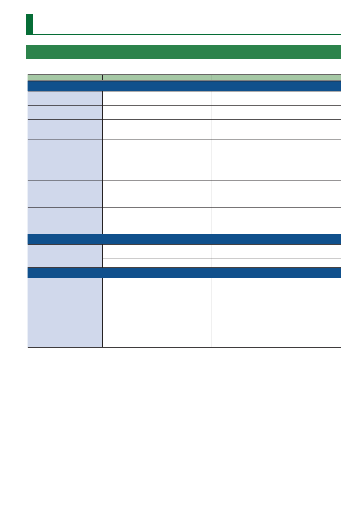
Appendix
Troubleshooting
If you suspect a malfunction, please check the following points. If this does not resolve the problem, contact a nearby Roland Service Center.
Problem Items to check Action Page
Video-related problems
Nothing is displayed on the multi-view
monitor.
No picture is input. Could you be inputting copy-protected (HDCP) video?
Analog RGB input is not output. Is the video source at the HDMI/RGB IN1 set to RGB IN1?
Video from the computer is corrupted.
Nothing is output from the SDI OUT
connector.
Can’t use COMPOSITION compositing
Still-image cannot be imported.
Audio-related Problems
No audio is output.
Audio volume is low.
Other Problems
Switching is not complete even when
the video fader is moved.
The panel indicators are too bright/
dark.
A USB ash drive cannot be read. Has the USB ash drive been formatted on the V-600UHD?
Does the connected monitor support a resolution and
refresh rate of 1920 x 1080/60 Hz (progressive) and HDCP?
When a rapidly moving video is input from a computer,
out-of-sync motion, icker, or other picture corruption may
occur.
Has the setting for inputting HDCP signal been made?
Could the System menu item “Aux/Composition” be set to
“Aux”?
Are you importing a still image whose format and
resolution are supported by the V-600UHD?
Could the volume of the connected amp or speaker be
lowered?
Could the audio be muted? In the Audio menu, defeat muting. p. 37
Factors such as continued use and transportation can
sometimes cause the video to fail to be switched completely.
Has indicator brightness been adjusted appropriately?
Nothing is displayed if the monitor is not compatible. –
If you want to input copy-protected (HDCP) video, set the
System menu “HDCP” setting to “On.”
In the factory-default state, HDMI/RGB IN1 is assigned to
HDMI IN1 input. The assignment must be changed to RGB
IN1 input.
This is called “tearing,” and does not indicate an equipment
malfunction.
When “HDCP” at the System menu is set to “On,” video is
output only from the HDMI OUT connectors.
No video is output via the SDI OUT connectors.
If the System menu item “Aux/Composition” is set to “Aux,” you
can’t use COMPOSITION.
If you want to use COMPOSITION, set “Aux/Composition” to
“Composition.”
Still images of unsupported formats or resolutions are not
recognized.
Prepare a still image whose format and resolution are
supported by the V-600UHD.
Adjust the volume appropriately. –
Perform calibration of the video fader.
Execute calibration, select “Fader Calibrate” in System menu.
Go to the System menu and use “LED Dimmer” to adjust
indicator brightness.
The V-600UHD does not recognize unformatted USB ash
drives.
Operation has been tested for commonly available USB ash
drives, but operation of all USB USB ash drives is not assured.
Depending on the manufacturer and type of the USB ash
drive, correct operation may not be possible.
p. 13
p. 10
–
p. 13
p. 41
p. 16
p. 41
p. 41
p. 25
47
Page 48

Appendix
Main Specications
Roland V-600UHD: 4K HDR MULTI-FORMAT VIDEO SWITCHER
9 Processing
Video Processing 4:4:4 (Y/Pb/Pr), 10-bit
Video, CEA-861-F
PC, VESA DMT 1600 x 1200/60 Hz (UXGA)
PC, CEA-861-F 1920 x 1080/60 Hz (FHD)
HDMI
PC, VESA CVT 1920 x 1200/60 Hz (WUXGA, Reduced blanking)
Supported Video Input
Formats (*1)
Supported Video Output
Formats (*1)
Video Eects
Audio Processing 24 bits/48 kHz
Audio formats
Audio Eects
(*1) Conforms to VESA DMT, VESA CVT, CEA-861-F
Color Gamut: Rec.709, Rec.2020
Dynamic Range: SDR, HDR PQ (HDR10), HDR HLG
(*2) Luminance Key, Chroma Key
PC, CEA-861-F
PC, VESA DMT 1600 x 1200/60 Hz (UXGA)
RGB
PC, CEA-861-F 1920 x 1080/60 Hz (FHD)
Video, SMPTE ST274 1080/59.94i, 1080/50i, 1080/59.94p, 1080/50p
SDI
Video, SMPTE ST2036 2160/59.94p (UHD 4K), 2160/50p (UHD 4K)
Video, SMPTE ST2048 2160/59.94p (DCI 4K), 2160/50p (DCI 4K)
Still Image Windows Bitmap File (.bmp), Maximum 4096 x 2160 pixels, 24-bit per pixel, uncompressed
Video, CEA-861-F
HDMI
PC, CEA-861-F 1920 x 1080/60 Hz (FHD), 3840 x 2160/60 Hz (UHD 4K), 4096 x 2160/60 Hz (DCI 4K)
MULTI-VIEW, PC, CEA-861-F 1920 x 1080/60 Hz (FHD)
Video, SMPTE ST274 1080/59.94p, 1080/50p
SDI
Video, SMPTE ST2036 2160/59.94p (UHD 4K), 2160/50p (UHD 4K)
Video, SMPTE ST2048 2160/59.94p (DCI 4K), 2160/50p (DCI 4K)
Transition Mix, Cut, Wipe (9 patterns)
Composition PinP, Key (*2), PinP + Key (*2)
DSK PinP, Key (*2), PinP + Key (*2)
Others Output Fade
SDI IN/OUT Linear PCM, 24 bits/48 kHz, 16 ch (Conforms to SMPTE 299M)
HDMI IN/OUT Linear PCM, 24 bits/48 kHz, 2 ch
Matrix mixer
Delay (1 ms units, max 500 ms)
Test tone output
1080/59.94i, 1080/50i, 1080/59.94p, 1080/50p, 2160/59.94p (UHD 4K), 2160/50p (UHD 4K),
2160/59.94p (DCI 4K), 2160/50p (DCI 4K)
3840 x 2160/30 Hz (UHD 4K), 3840 x 2160/60 Hz (UHD 4K), 4096 x 2160/30 Hz (DCI 4K),
4096 x 2160/60 Hz (DCI 4K)
1080/59.94p, 1080/50p, 2160/59.94p (UHD 4K), 2160/50p (UHD 4K), 2160/59.94p (DCI 4K),
2160/50p (DCI 4K)
9 Connectors
HDMI IN 1–4 connectors HDMI type A (HDMI 2.0)
Input Connectors
Output Connectors
Other Connectors
(*3) XLR type: 1 GND, 2 HOT, 3 COLD
SDI IN 5–6 connectors BNC type (12G/3G/HD-SDI, Conforms to SMPTE 2082, 424M (Level-A, Level-B), 292M)
RGB IN 1 connector HD DB-15 type (Analog RGB, Select HDMI IN 1 or RGB IN 1 using menu)
AUDIO IN L/R connectors (*3) XLR-3-31 type (balanced)
SDI OUT connector BNC type (12G/3G-SDI, Conforms to SMPTE 2082, 424M (Level-A, Level-B))
HDMI OUT 1–3 connectors HDMI type A (HDMI 2.0)
MULTI-VIEW connector HDMI type A (HDMI 1.4)
AUDIO OUT L/R connectors (*3) XLR-3-32 type (balanced)
PHONES jack Stereo miniature phone type
USB MEMORY port USB A type (for USB ash drive)
RS-232 connector DB-9 type (Male) (for Remote Control)
LAN port RJ45 type, 100BASE-TX (for Remote Control)
TALLY/GPI por t DB-25 type (Female) (Tally: 16, GPI: 8)
48
Page 49

9 Audio Input/Output Characteristics
Input Level AUDIO IN L/R +4 dBu (Maximum: +24 dBu)
Input Impedance AUDIO IN L/R 15 kΩ
Output Level
Output Impedance
AUDIO OUT L/R +4 dBu (Maximum: +24 dBu)
PHONES 92 mW + 92 mW (32 Ω)
AUDIO OUT L/R 600 Ω
PHONES 10 Ω
9 Others
Power Consumption 80 W
482 (W) x 300 (D) x 109 (H) mm
Dimensions
Weight
Operation Temperature
Accessories
19 (W) x 11-13/16 (D) x 4-5/16 (H) inches
* When rack mount angles are tted.
5.3 kg
11 lbs 11 oz
* Including rack mount angles.
+5 to +40 degrees Celsius
+41 to +104 degrees Fahrenheit
Owner’s Manual
Power cord
Rack-mount angle x 2
Appendix
* 0 dBu = 0.775 Vrms
* This product is a Class A digital device under FCC part 15.
49
Page 50

Appendix
Dimensions
Unit: mm
83.4 6.5
437
283.6 15.6
56.7
108.6
50
Page 51
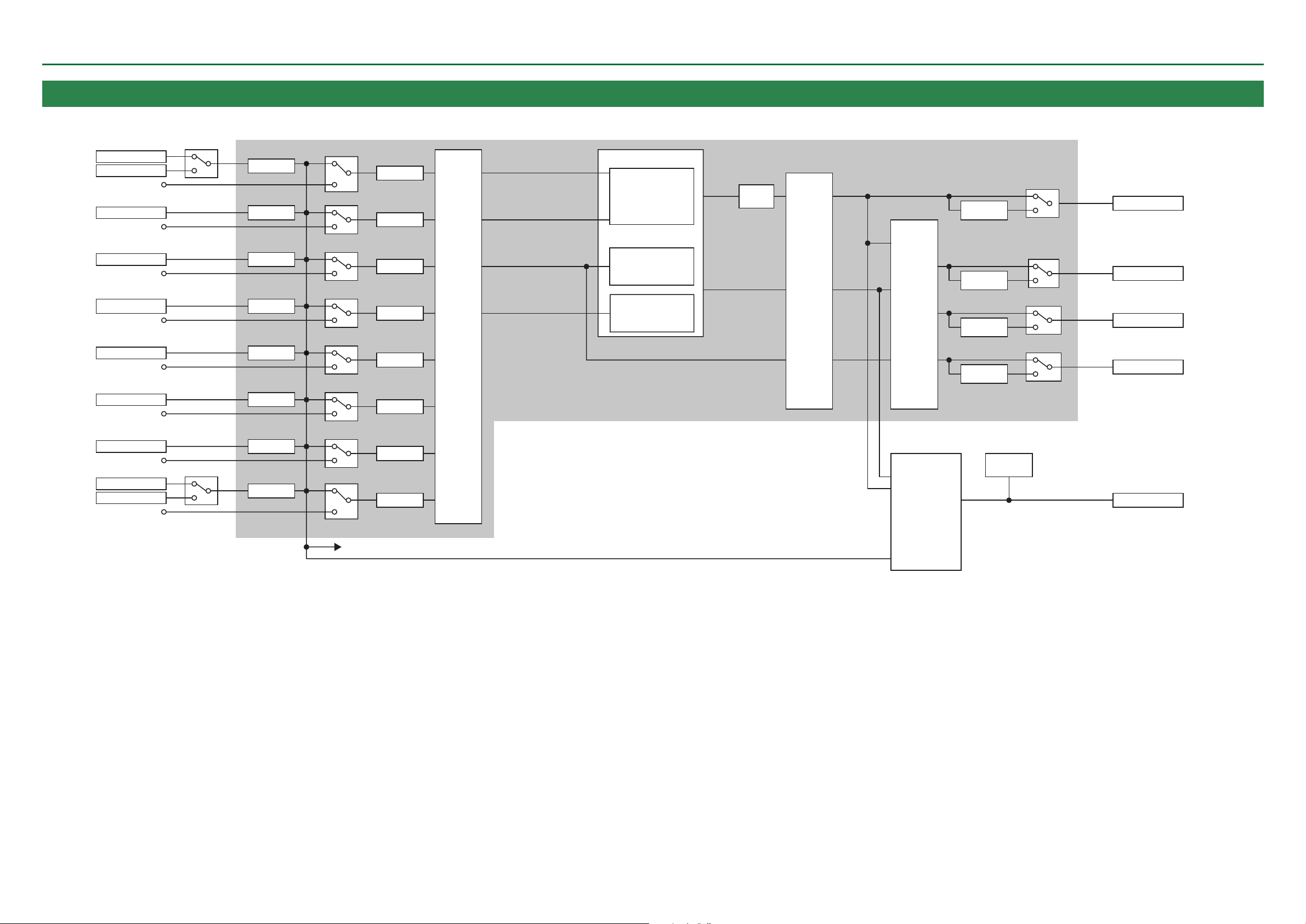
VIDEO Block Diagram
HDMI OUTPUT 1
HDMI OUTPUT 2
HDMI OUTPUT 3
Appendix
HDMI IN1
RGB IN1
HDMI IN2
HDMI IN3
HDMI IN4
SDI IN5
SDI IN6
STILL1
STILL2
PG
HDMI 2.0
RGB
Shared Input
HDMI 2.0
Shared Input
HDMI 2.0
Shared Input
HDMI 2.0
Shared Input
12G/3G/HD SDI
Shared Input
12G/3G/HD SDI
Shared Input
STILL IMAGE1
Shared Input
STILL IMAGE2
Pattern Gen.
Shared Input
CSC DR
CSC DR
CSC DR
CSC DR
CSC DR
CSC DR
CSC DR
CSC DR
Scaling
Scaler
Scaler
Scaler
Scaler
Scaler
Scaler
Scaler
Scaler
XPT
PGM
PST
Composition
Source
DSK
Source
VIDEO
MIXER
Composition
(PinP1/KEY1)
DSK
(PinP2/KEY2)
444 PROCESS
PGM
PVW
AUX
Output
Fade
CSC
Scaler
PGM
PVW
AUX
SELECTOR
MULTI-VIEW
(HDR-SDR conv.)
4K-HD
Down Conv.
4K-HD
Down Conv.
4K-HD
Down Conv.
4K-HD
Down Conv.
MENU
OSD
12G/3G SDI
HDMI 2.0
HDMI 2.0
HDMI 2.0
HDMI 1.4
SDI OUTPUT
MULTI-VIEW
to Shared Input
51
Page 52

HDMI OUTPUT 1
HDMI OUTPUT 2
HDMI OUTPUT 3
TEST TONE
444 PROCESS
HDMI 2.0
HDMI OUTPUT 1
HDMI OUTPUT 2
HDMI OUTPUT 3
HDMI 2.0
HDMI 2.0
XPT
AUX
DSK
Source
SELECTOR
MULTI-VIEW
(HDR-SDR conv.)
MULTI-VIEW
HDMI 1.4
CSC
Scaler
MENU
OSD
Composition
Source
Composition
(PinP1/KEY1)
PVW
AUX
PVW
DSK
(PinP2/KEY2)
HDMI IN3
HDMI 2.0
Shared Input
HDMI IN4
HDMI 2.0
Shared Input
12G/3G/HD SDI
SDI IN5
Shared Input
12G/3G/HD SDI
SDI IN6
Shared Input
STILL IMAGE1
STILL1
Shared Input
STILL2
STILL IMAGE2
Pattern Gen.
Shared Input
to Shared Input
Scaler
Scaler
Scaler
Scaler
CSC DR
CSC DR
CSC DR
CSC DR
4K-HD
Down Conv.
4K-HD
Down Conv.
4K-HD
Down Conv.
CSC DR
Scaler
Scaler
CSC DR
PG
AUDIO Block Diagram
HDMI IN1
HDMI IN2
HDMI IN3
HDMI IN4
HDMI 2.0
HDMI 2.0
HDMI 2.0
HDMI 2.0
2
2
2
2
Delay: Max 500 ms
Delay
Delay
Delay
Delay
Level: -INF– +10 dB
Mute Follow
Follow
Mute
Mute
Follow
Mute
Follow
Level
Level
Level
Level
Level
Level
Level
Level
MAIN AUX
16
2
Delay
Max 500 ms
Delay
Max 500 ms
Level
-INF –+10 dB
Level
-INF–+10 dB
MAIN AUX
Source Select
Appendix
16
2
12G/3G SDI
HDMI 2.0
SDI OUTPUT
SDI IN5
SDI IN6
AUDIO IN
12G/3G/HD SDI
16
16
12G/3G/HD SDI
2
AUDIO IN
Nominal Input Level: +4 dBu
Non Clip Max Input Level: +24 dBu
2
TEST TONE
AD
(INPUT)
Digital Gain
-48 dB–+24 dB
O / L: 1 kHz, R: 2 kHz
Delay
Delay
SIG/PEAK
Delay
Mute
Follow
2
Mute
Follow
2
Mute
Follow
Level
Level
Level
Level
Level
Level
2
2
2
HDMI 2.0
HDMI 2.0
HDMI 1.4
MULTI-VIEW
Level
Level
LEVEL
METER
DA
DA
AUDIO OUT
Nominal Output Level: +4 dBu
Non Clip Max Output Level: +24 dBu
PHONES
Nominal Output Level:
92 mW + 92 mW (32 Ω load)
AUDIO OUT
PHONES
Level
Level
2
-INF–+10 dB
2
-INF–+10 dB
52
 Loading...