

Page 1
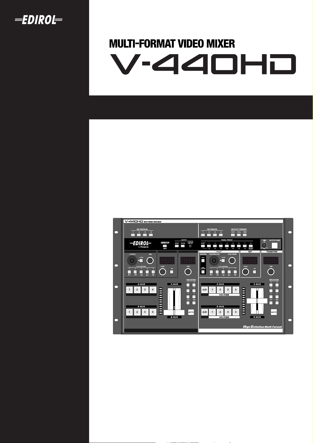
Owner's Manual
201b
Before using this unit, carefully read the sections entitled: “IMPORTANT SAFETY
INSTRUCTIONS” (p. 2), “USING THE UNIT SAFELY” (p. 4), and “IMPORTANT NOTES” (p. 6).
These sections provide important information concerning the proper operation of the unit.
Additionally, in order to feel assured that you have gained a good grasp of every feature
provided by your new unit, Owner’s Manual should be read in its entirety. The manual
should be saved and kept on hand as a convenient reference.
202
Copyright © 2005 ROLAND CORPORATION
All rights reserved. No part of this publication may be reproduced in any form without the
written permission of ROLAND CORPORATION.
Page 2
WARNING: To reduce the risk of fire or electric shock, do not expose this apparatus to rain or moisture.
CAUTION
RISK OF ELECTRIC SHOCK
DO NOT OPEN
ATTENTION: RISQUE DE CHOC ELECTRIQUE NE PAS OUVRIR
CAUTION: TO REDUCE THE RISK OF ELECTRIC SHOCK,
DO NOT REMOVE COVER (OR BACK).
NO USER-SERVICEABLE PARTS INSIDE.
REFER SERVICING TO QUALIFIED SERVICE PERSONNEL.
The lightning flash with arrowhead symbol, within an
equilateral triangle, is intended to alert the user to the
presence of uninsulated “dangerous voltage” within the
product’s enclosure that may be of sufficient magnitude to
constitute a risk of electric shock to persons.
The exclamation point within an equilateral triangle is
intended to alert the user to the presence of important
operating and maintenance (servicing) instructions in the
literature accompanying the product.
INSTRUCTIONS PERTAINING TO A RISK OF FIRE, ELECTRIC SHOCK, OR INJURY TO PERSONS.
IMPORTANT SAFETY INSTRUCTIONS
SAVE THESE INSTRUCTIONS
WARNING - When using electric products, basic precautions should always be followed, including the following:
1. Read these instructions.
2. Keep these instructions.
3. Heed all warnings.
4. Follow all instructions.
5. Do not use this apparatus near water.
6. Clean only with a dry cloth.
7. Do not block any of the ventilation openings. Install in
accordance with the manufacturers instructions.
8. Do not install near any heat sources such as radiators,
heat registers, stoves, or other apparatus (including
amplifiers) that produce heat.
9. Do not defeat the safety purpose of the polarized or
grounding-type plug. A polarized plug has two blades with
one wider than the other. A grounding type plug has two
blades and a third grounding prong. The wide blade or the
third prong are provided for your safety. If the provided plug
does not fit into your outlet, consult an electrician for
replacement of the obsolete outlet.
10. Protect the power cord from being walked on or pinched
particularly at plugs, convenience receptacles, and the
point where they exit from the apparatus.
11. Only use attachments/accessories specified
by the manufacturer.
12. Unplug this apparatus during lightning storms or when
unused for long periods of time.
13. Refer all servicing to qualified service personnel. Servicing
is required when the apparatus has been damaged in any
way, such as power-supply cord or plug is damaged, liquid
has been spilled or objects have fallen into the apparatus,
the apparatus has been exposed to rain or moisture, does
not operate normally, or has been dropped.
2
For the U.K.
WARNING:
IMPORTANT:
As the colours of the wires in the mains lead of this apparatus may not correspond with the coloured markings identifying
the terminals in your plug, proceed as follows:
The wire which is coloured GREEN-AND-YELLOW must be connected to the terminal in the plug which is marked by the
letter E or by the safety earth symbol or coloured GREEN or GREEN-AND-YELLOW.
The wire which is coloured BLUE must be connected to the terminal which is marked with the letter N or coloured BLACK.
The wire which is coloured BROWN must be connected to the terminal which is marked with the letter L or coloured RED.
THIS APPARATUS MUST BE EARTHED
THE WIRES IN THIS MAINS LEAD ARE COLOURED IN ACCORDANCE WITH THE FOLLOWING CODE.
GREEN-AND-YELLOW: EARTH, BLUE: NEUTRAL, BROWN: LIVE
Page 3
For EU Countries
This product complies with the requirements of European Directives EMC 89/336/EEC and LVD 73/23/EEC.
For the USA
FEDERAL COMMUNICATIONS COMMISSION
RADIO FREQUENCY INTERFERENCE STATEMENT
This equipment has been tested and found to comply with the limits for a Class B digital device, pursuant to Part 15 of the
FCC Rules. These limits are designed to provide reasonable protection against harmful interference in a residential
installation. This equipment generates, uses, and can radiate radio frequency energy and, if not installed and used in
accordance with the instructions, may cause harmful interference to radio communications. However, there is no guarantee
that interference will not occur in a particular installation. If this equipment does cause harmful interference to radio or
television reception, which can be determined by turning the equipment off and on, the user is encouraged to try to correct the
interference by one or more of the following measures:
– Reorient or relocate the receiving antenna.
– Increase the separation between the equipment and receiver.
– Connect the equipment into an outlet on a circuit different from that to which the receiver is connected.
– Consult the dealer or an experienced radio/TV technician for help.
This device complies with Part 15 of the FCC Rules. Operation is subject to the following two conditions:
(1) This device may not cause harmful interference, and
(2) This device must accept any interference received, including interference that may cause undesired operation.
Unauthorized changes or modification to this system can void the users authority to operate this equipment.
This equipment requires shielded interface cables in order to meet FCC class B Limit.
For Canada
NOTICE
This Class B digital apparatus meets all requirements of the Canadian Interference-Causing Equipment Regulations.
AVIS
Cet appareil numérique de la classe B respecte toutes les exigences du Règlement sur le matériel brouilleur du Canada.
3
Page 4
USING THE UNIT SAFELY
Used for instructions intended to alert
the user to the risk of death or severe
injury should the unit be used
improperly.
Used for instructions intended to alert
the user to the risk of injury or material
damage should the unit be used
improperly.
* Material damage refers to damage or
other adverse effects caused with
respect to the home and all its
furnishings, as well to domestic
animals or pets.
001
• Before using this unit, make sure to read the
instructions below, and the Owner’s Manual.
..........................................................................................................
001-50
• Connect mains plug of this model to a mains
socket outlet with a protective earthing
connection.
..........................................................................................................
002a
• Do not open or perform any internal modifications on the unit.
..........................................................................................................
003
• Do not attempt to repair the unit, or replace parts
within it (except when this manual provides
specific instructions directing you to do so). Refer
all servicing to your retailer, the nearest Roland Service
Center, or an authorized Roland distributor, as listed on
the “Information” page.
..........................................................................................................
004
• Never use or store the unit in places that are:
• Subject to temperature extremes (e.g., direct
sunlight in an enclosed vehicle, near a heating
duct, on top of heat-generating equipment); or
are
• Damp (e.g., baths, washrooms, on wet floors); or are
• Humid; or are
• Exposed to rain; or are
• Dusty; or are
• Subject to high levels of vibration.
..........................................................................................................
007
• Make sure you always have the unit placed so it is
level and sure to remain stable. Never place it on
stands that could wobble, or on inclined surfaces.
..........................................................................................................
008a
• The unit should be connected to a power supply
only of the type described in the operating
instructions, or as marked on the rear side of unit.
The symbol alerts the user to important instructions
or warnings.The specific meaning of the symbol is
determined by the design contained within the
triangle. In the case of the symbol at left, it is used for
general cautions, warnings, or alerts to danger.
The symbol alerts the user to items that must never
be carried out (are forbidden). The specific thing that
must not be done is indicated by the design contained
within the circle. In the case of the symbol at left, it
means that the unit must never be disassembled.
The ● symbol alerts the user to things that must be
carried out. The specific thing that must be done is
indicated by the design contained within the circle. In
the case of the symbol at left, it means that the powercord plug must be unplugged from the outlet.
008e
• Use only the attached power-supply cord. Also,
the supplied power cord must not be used with
any other device.
..........................................................................................................
009
• Do not excessively twist or bend the power cord,
nor place heavy objects on it. Doing so can
damage the cord, producing severed elements
and short circuits. Damaged cords are fire and shock
hazards!
..........................................................................................................
011
• Do not allow any objects (e.g., flammable
material, coins, pins); or liquids of any kind
(water, soft drinks, etc.) to penetrate the unit.
..........................................................................................................
012a
• Immediately turn the power off, remove the
power cord from the outlet, and request servicing
by your retailer, the nearest Roland Service
Center, or an authorized Roland distributor, as listed on
the “Information” page when:
• The power-supply cord, or the plug has been
damaged; or
• If smoke or unusual odor occurs
• Objects have fallen into, or liquid has been spilled onto
the unit; or
• The unit has been exposed to rain (or otherwise has
become wet); or
• The unit does not appear to operate normally or
exhibits a marked change in performance.
..........................................................................................................
014
• Protect the unit from strong impact.
(Do not drop it!)
..........................................................................................................
..........................................................................................................
4
Page 5
015
• Do not force the unit’s power-supply cord to
share an outlet with an unreasonable number of
other devices. Be especially careful when using
extension cords—the total power used by all devices you
have connected to the extension cord’s outlet must never
exceed the power rating (watts/amperes) for the
extension cord. Excessive loads can cause the insulation
on the cord to heat up and eventually melt through.
..........................................................................................................
016
• Before using the unit in a foreign country, consult
with your retailer, the nearest Roland Service
Center, or an authorized Roland distributor, as
listed on the “Information” page.
..........................................................................................................
026
• Do not put anything that contains water (e.g.,
flower vases) on this unit. Also, avoid the use of
insecticides, perfumes, alcohol, nail polish, spray
cans, etc., near the unit. Swiftly wipe away any liquid that
spills on the unit using a dry, soft cloth.
..........................................................................................................
101a
• The unit should be located so that its location or
position does not interfere with its proper ventilation.
..........................................................................................................
102b
• Always grasp only the plug on the power-supply
cord when plugging into, or unplugging from, an
outlet or this unit.
..........................................................................................................
103a
• At regular intervals, you should unplug the
power plug and clean it by using a dry cloth to
wipe all dust and other accumulations away from
its prongs. Also, disconnect the power plug from the
power outlet whenever the unit is to remain unused for
an extended period of time. Any accumulation of dust
between the power plug and the power outlet can result
in poor insulation and lead to fire.
..........................................................................................................
104
• Try to prevent cords and cables from becoming
entangled. Also, all cords and cables should be
placed so they are out of the reach of children.
..........................................................................................................
106
• Never climb on top of, nor place heavy objects on
the unit.
..........................................................................................................
107b
• Never handle the power cord or its plugs with
wet hands when plugging into, or unplugging
from, an outlet or this unit.
..........................................................................................................
108a
• Before moving the unit, disconnect the power
plug from the outlet, and pull out all cords from
external devices.
..........................................................................................................
109a
• Before cleaning the unit, turn off the power and
unplug the power cord from the outlet (p. 23).
..........................................................................................................
110a
• Whenever you suspect the possibility of lightning
in your area, pull the plug on the power cord out
of the outlet.
..........................................................................................................
118c
• Keep any screws you may remove and the
included screws in a safe place out of children’s
reach, so there is no chance of them being
swallowed accidentally.
..........................................................................................................
5
Page 6

IMPORTANT NOTES
291a
In addition to the items listed under “USING THE UNIT
SAFELY” on page 4, please read and observe the
following:
Power Supply
301
• Do not connect this unit to same electrical outlet that is
being used by an electrical appliance that is controlled by
an inverter (such as a refrigerator, washing machine,
microwave oven, or air conditioner), or that contains a
motor. Depending on the way in which the electrical
appliance is used, power supply noise may cause this unit
to malfunction or may produce audible noise. If it is not
practical to use a separate electrical outlet, connect a
power supply noise filter between this unit and the
electrical outlet.
307
• Before connecting this unit to other devices, turn off the
power to all units. This will help prevent malfunctions
and/or damage to TV monitors or other devices.
308
• Although the LCD and LEDs are switched off when the
POWER switch is switched off, this does not mean that the
unit has been completely disconnected from the source of
power. If you need to turn off the power completely, first
turn off the POWER switch, then unplug the power cord
from the power outlet. For this reason, the outlet into
which you choose to connect the power cord’s plug
should be one that is within easy reach and readily accessible.
Placement
352a
• This device may interfere with radio and television
reception. Do not use this device in the vicinity of such
receivers.
352b
• Noise may be produced if wireless communications
devices, such as cell phones, are operated in the vicinity of
this unit. Such noise could occur when receiving or initiating a call, or while conversing. Should you experience
such problems, you should relocate such wireless devices
so they are at a greater distance from this unit, or switch
them off.
355b
• When moved from one location to another where the
temperature and/or humidity is very different, water
droplets (condensation) may form inside the unit. Damage
or malfunction may result if you attempt to use the unit in
this condition. Therefore, before using the unit, you must
allow it to stand for several hours, until the condensation
has completely evaporated.
Copyright
851
• Unauthorized recording, distribution, sale, lending, public
performance, broadcasting, or the like, in whole or in part,
of a work (musical composition, video, broadcast, public
performance, or the like) whose copyright is held by a
third party is prohibited by law.
853
• Do not use this unit for purposes that could infringe on a
copyright held by a third party. We assume no responsibility whatsoever with regard to any infringements of
third-party copyrights arising through your use of this
unit.
Maintenance
401a
• For everyday cleaning wipe the unit with a soft, dry cloth
or one that has been slightly dampened with water. To
remove stubborn dirt, use a cloth impregnated with a
mild, non-abrasive detergent. Afterwards, be sure to wipe
the unit thoroughly with a soft, dry cloth.
402
• Never use benzine, thinners, alcohol or solvents of any
kind, to avoid the possibility of discoloration and/or
deformation.
Repairs and Data
452
• Please be aware that all data contained in the unit’s
memory may be lost when the unit is sent for repairs.
Important data should always be written down on paper
(when possible). During repairs, due care is taken to avoid
the loss of data. However, in certain cases (such as when
circuitry related to memory itself is out of order), we
regret that it may not be possible to restore the data, and
Roland assumes no liability concerning such loss of data.
Additional Precautions
551
• Please be aware that the contents of memory can be
irretrievably lost as a result of a malfunction, or the
improper operation of the unit. To protect yourself against
the risk of loosing important data, we recommend that
you periodically save a backup copy of important data
you have stored in the unit’s memory.
552
• Unfortunately, it may be impossible to restore the
contents of data that was stored in the unit’s memory once
it has been lost. Roland Corporation assumes no liability .
553
• Use a reasonable amount of care when using the unit’s
buttons, sliders, or other controls; and when using its jacks
and connectors. Rough handling can lead to malfunctions.
556
• When connecting / disconnecting all cables, grasp the
connector itself—never pull on the cable. This way you
will avoid causing shorts, or damage to the cable’s
internal elements.
557
•A small amount of heat will radiate from the unit during
normal operation.
559a
• When you need to transport the unit, package it in the box
(including padding) that it came in, if possible. Otherwise,
you will need to use equivalent packaging materials.
add
• This device allows you to switch images or turn video
effects on/off at high speed. For some people, viewing
such images can cause headache, nausea, or other
discomfort. Do not use this device to create video that
might cause these types of health problems. Roland
Corporation will accept no responsibility for any such
health problems that may occur in yourself or in viewers.
6
Page 7

Contents
USING THE UNIT SAFELY ............................4
IMPORTANT NOTES......................................6
Contents.........................................................7
Main Features ................................................8
Organization of the V-440HD.....................................8
Multiformat Switcher................................................... 9
HD/RGB Inputs......................................................9
SD Inputs..................................................................9
Multiscreen Displays..............................................9
Connection Example .................................................. 10
Live Switching.......................................................10
Examples of Devices That Can Be Used............ 10
Before Using the V-440HD..........................11
Check the Contents of the Package..........................11
Names of Things and What They Do .........12
Top Panel ..................................................................... 12
SD Section ..............................................................14
HD/RGB Section...................................................16
Settings Section .....................................................17
Rear Panel.................................................................... 18
HD Output Section ...............................................19
SD Input/Output Section ....................................19
HD/RGB Input Section........................................ 19
Connections and Settings ..........................20
Making the Connections............................................ 20
Precautions When Making Settings.........................22
With Rack-Mounting and Other Enclosures.....22
Basic Operation...........................................23
Turning On the Power .........................................23
Turning Off the Power ......................................... 23
Outputting and Stopping the Final Output............ 23
Making the Fade-out Settings .............................23
Making Various Settings ...........................................24
Displaying Menus................................................. 24
Menu Operations ..................................................25
Shortcuts to the Menu Parameters .....................25
Input and Output Settings ..........................26
Selecting the Output Format..................................... 26
Making the Output Settings ................................ 26
Setting the HD/RGB Input .......................................27
Setting the SD Input ................................................... 27
HD/RGB Section Operations ......................28
Switching in the HD/RGB Section..................... 28
HD/RGB Section P in P Effects ..........................30
HD/RGB Section Key Composite Effects .........32
SD Section Operations ...............................34
Switching in the SD Section.................................34
SD Section P in P Effects ......................................35
SD Section Key Composite Effects .....................37
Using the PANEL PRESET Buttons .........................38
Copying Presets.....................................................38
Exchanging Presets ...............................................39
Multi-Screen Output ..................................................39
Connection Instructions for Multi-Screen Output
39
Making the Multi-Screen Settings ......................40
Advanced Multi-Screen Settings ........................41
Temporarily Switching Off the Multi-Screen
Function for the Master and Slave Devices.......41
Switching Between NTSC and PAL ...................42
Displaying Test Patterns ......................................42
Reference .................................................... 43
About the HD/RGB IN Connectors (D-Sub)..........43
About the RGB OUT Connectors (D-Sub)...............43
About the TALLY Connectors ..................................44
About the REMOTE Connector................................44
Controlling the V-440HD from an External Device
Via MIDI ......................................................................45
Controlling the V-440HD from an External
Device Via MIDI....................................................45
MIDI Messages Handled by the V-440HD........46
Control Using V-LINK .........................................46
Instructions for Using V-LINK ...........................46
Installing the Rack Mount Hardware......................47
Instructions for Attaching the Rack Mount
Hardware ...............................................................47
About Maintenance ....................................................47
Daily Maintenance................................................47
About the Fan ........................................................47
Menu Parameters........................................ 48
REMOTE Command Reference ................. 56
Commands Transmitted from External Devices to
the V-440HD................................................................56
Commands Transmitted from the V-440HD to
External Devices .........................................................58
MIDI implementation................................... 59
MIDI IMPLEMENTATION CHART .......................66
Block Diagram............................................. 67
Settings and Parameters............................ 68
HD Size16:9 Output....................................................68
RGB Video Live Output.............................................69
SD Size4:3 Output.......................................................70
HD-SDI Recording......................................................71
Troubleshooting ......................................... 72
Memo ........................................................... 74
Menu Settings Memo .................................................74
Index ............................................................ 77
Main specifications..................................... 79
Other Operations.........................................38
7
Page 8
Main Features
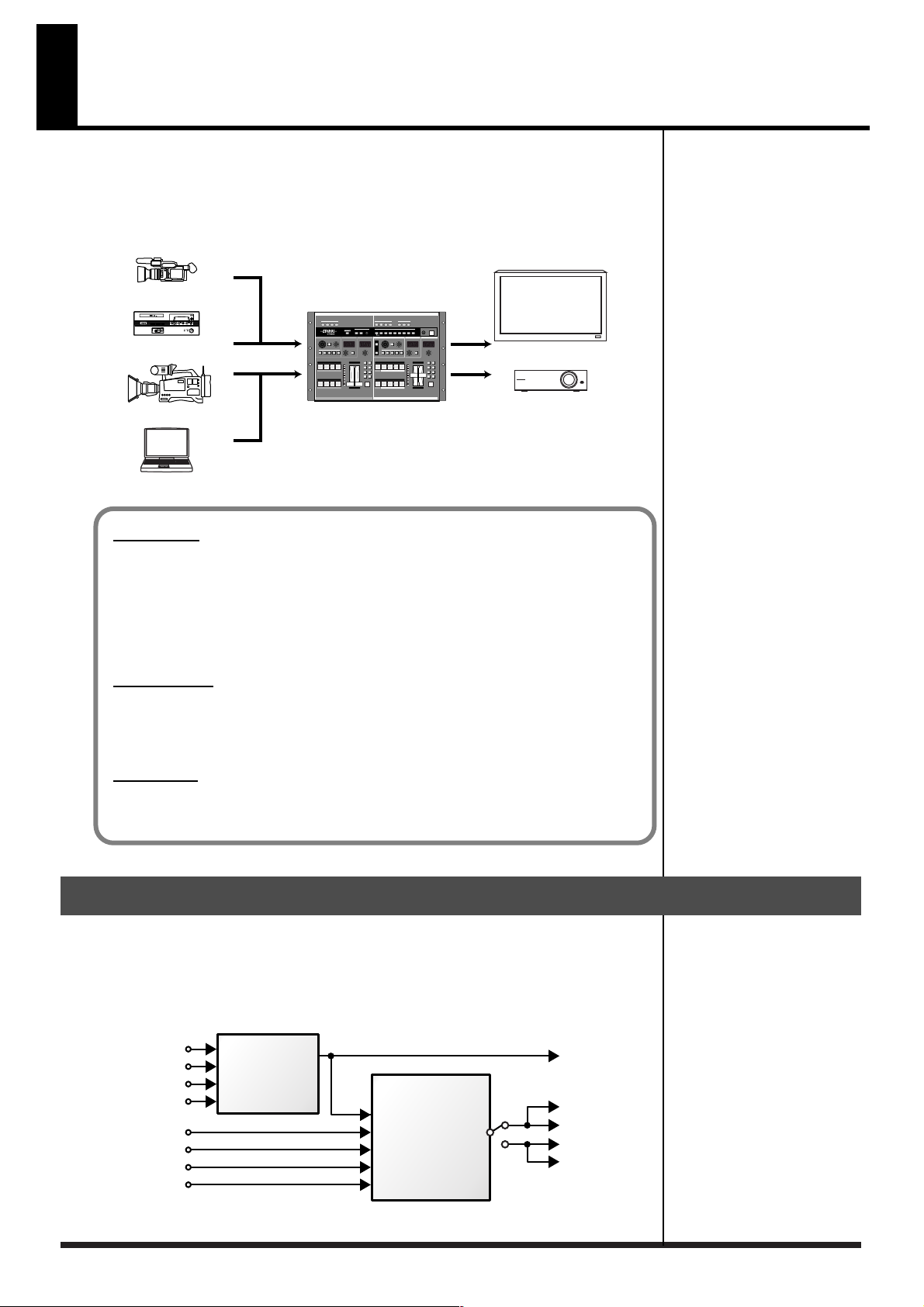
The V-440HD multiformat live switcher is capable of switching between four HD/
RGB input systems and four SD input systems for seamless switching between HD,
RGB, and SD inputs. There is no need to obtain separate converters to handle each
type of format. Although housed in a compact body, this one device is capable of
handling a wide variety of formats.
SD VCR
SD Video Presenter
HD VCR
PC
V-440HD
Plasuma Display
Projector
About HD
An abbreviation for “High Definition,” HD is a generic term for television formats that, in
comparison to conventional TV formats, provide higher resolution and an improved angle of
view, and deliver a heightened sense of presence by means of large-screen. This is also referred
to as HDTV. Although there are a number of different types of HD, which can vary depending
on the country where the technology was developed, the V-440HD utilizes the standards
recommended in BT.709-3, established by the ITU in February, 1998.
About RGB
This format, used for output of video images with computers and other digital devices, uses
video signals whereby each of three main colors, red (R), green (G), and blue (B), are handled
separately.
About SD
An abbreviation for Standard Definition, this refers to formats currently in general use (such as
480I), as opposed to HD (High Definition).
Organization of the V-440HD
The V-440HD comprises two main sections, an “HD/RGB section,” which is used to
mix all video signals, and an “SD section,” used for managing all SD video. The
resulting mixes of composite video and S-video signals from the SD section (PGM
output) are sent to the HD/RGB section, where the HD and RGB video are mixed
and then output in either HD or RGB format.
SD IN 1
SD IN 2
SD IN 3
SD IN 4
HD/RGB IN 1
HD/RGB IN 2
HD/RGB IN 3
HD/RGB IN 4
8
SD
Section
SD
PGM
HD/RGB
Section
SD PGM OUT
HD OUT 1
HD OUT 2
RGB OUT 1
RGB OUT 2
Page 9
Multiformat Switcher
The V-440HD converts and seamlessly switches signals in HD, RGB, and SD format
to the selected final output format.
HD Effects
• The V-440HD uses a variety of effects, including transitions (effects used when
switching video images), P in P, and key composite effects.
• Using the V-440HD in combination with an SD video switcher allows you to
compose video using up to six different effects simultaneously.
Equipped with High-Performance SD-to-HD/RGB Up-Converter
The V-440HD features an up-converter that converts SD output to the final output
format. This system enables up-conversion of SD video to HD and RGB with
superior image quality.
Main Features
HD/RGB Inputs
• The HD/RGB inputs provide for the input of four channels of HD or RGB video.
• HD inputs are compatible with 1080I as well as the typical 720p format. RGB inputs
are compatible with VGA (640 x 480), SXGA (1280 x 1024) formats.
• The HD/RGB inputs allow input through BNC and D-Sub connectors
• Any HD/RGB input component BNC and D-Sub connectors not in use for input can
be used as loop thru outputs.
SD Inputs
• The V-440HD features four input channels.
• SD inputs are compatible with both S-Video and component video.
•A preview output is provided for each of the SD inputs 1-4.
SD Video Mixer
• Capable of switching only SD video input.
• PGM output from the SD video mixer can be switched after being input to the
multiformat switcher. In addition, SD PGM output can be output as S-Video or
composite video.
• Effects, including transitions (effects used when switching video images), P in P, and
key composite effects can be used.
Multiscreen Displays
You can use to synchronize multiple V-440HDs easily, and use simple settings to
output the signals from one V-440HD to multiscreen displays. This eliminates any
need to prepare video for each individual screen.
9
Page 10
Main Features
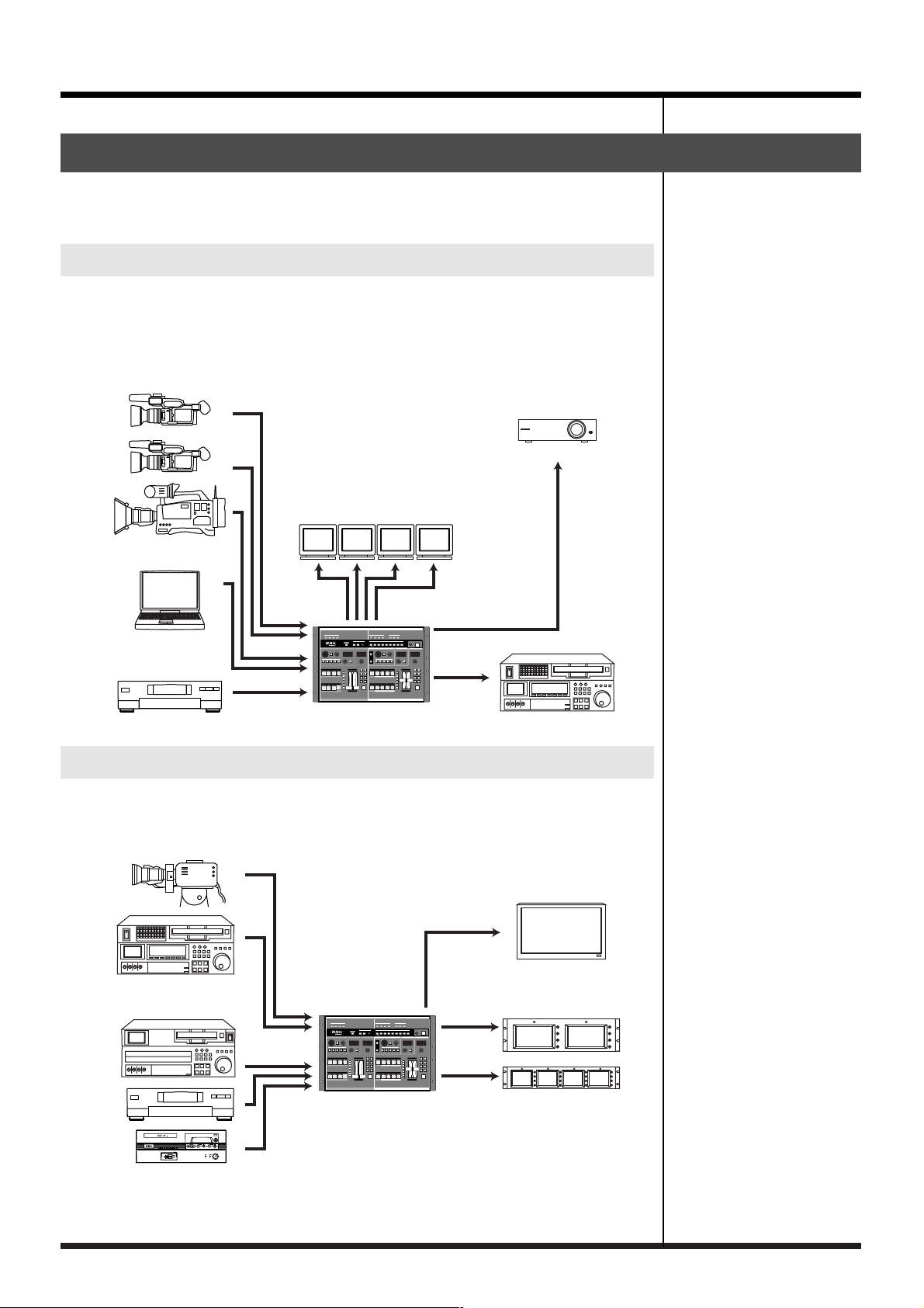
Connection Example
A variety of video formats can be handled with a single V-440HD, providing great
flexibility for various different applications.
Live Switching
The V-440HD can be used for live switching with video productions that mix
material in SD and HD formats. You can freely switch video from HD cameras and
SD cameras and use chroma key and luminance key effects with characters
displayed by a computer.
Stage Camera
Projector
Preview Monitor
PC
SD Video Deck
V-440HD
Examples of Devices That Can Be Used
Due to its extensive compatibility with HD, RGB, and SD formats, the V-440HD
provides a flexible system that can be tailored for any need and budget.
HD Video Equipment
HD Video Recorder
Plasuma Display
10
SD Video Equipment
Preview Monitor
V-440HD
Page 11
Before Using the V-440HD
Check the Contents of the Package
The V-440HD includes the following accessories. Please take a moment to confirm
that all of these items have been included with the V-440HD.
If you find that any item is missing, contact your nearest Roland Service Center.
V-440HD
Power cord
* Use only the attached power cord. Also, must not remove the ferrite core from the supplied
power code.
Owner’s Manual (this volume)
11
Page 12
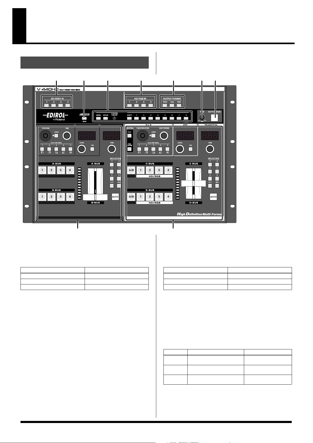
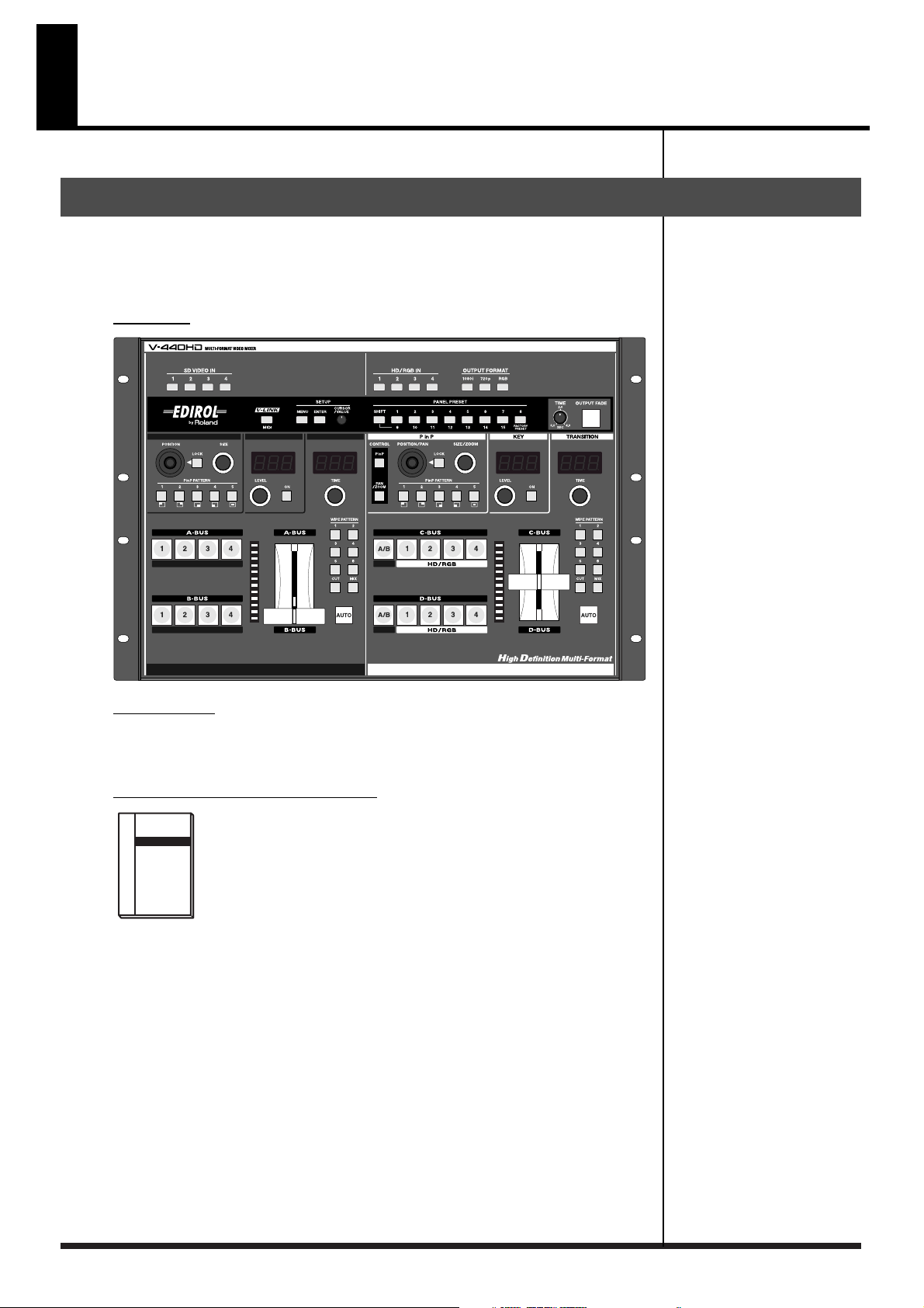
Names of Things and What They Do
Top Panel
1.
2.
3.
4.
5.
1324
567
89
SD IN Buttons 1-4........................................................... (p. 27)
• These indicate the status of the video signals input to each of the
SD IN inputs (p. 19).
Button
Lit (Red)
Lit (Green) Input of S-video signal
Off No signal input
• Holding down the MENU button while pressing an SD IN
button displays the SD input menu parameters (p. 27).
MIDI Button...................................................................... (p. 45)
This switches the MIDI functions on and off.
The MIDI button is lit when the V-LINK mode is ON.
You can have the status of the V-LINK mode be indicated by the
illumination of the MIDI button. Select “V-LINK Indicator” in “MIDI
Switch Mode” (p. 55) in the menu.
Settings Section ............................................................. (p. 17)
Used for making various settings for the V-440HD.
For descriptions of each of the controllers, refer to
17).
Video Signal Status
Input of composite signal
Settings Section (p.
HD/RGB IN Buttons 1-4 ..................................................(p. 27)
• These indicate the status of the video signals input to each of the
HD/RGB IN inputs (p. 19).
Button
Lit (Red)
Lit (Green) Input of HD component signal
Off No signal input
• Holding down the MENU button while pressing an HD/RGB
IN button brings up the HD/RGB input menu parameters (p.
27).
OUTPUT FORMAT Buttons ............................................(p. 26)
• Press an OUTPUT FORMAT button to select the format for the
video output from the HD OUT connectors (p. 19) or RGB OUT
connectors (p. 19). The selected button lights up.
Button
1080i 1080/60i (factory default set-
720p 720/60p (factory default set-
RGB 1024x768/60 RGB OUT Connectors 1,
Output Video Format Output Connectors
ting)
ting)
Video Signal Status
Input of RGB signal
HD OUT Connectors 1, 2
HD OUT Connectors 1, 2
2
12
* You can change the video format selected with each button in the
menu (p. 26).
Page 13
TIME Knob ...................................................................... (p. 23)
Enables setting of the time for the video to fade when the OUTPUT FADE
button is pressed. Time can be set from 0.0 to 4.0 seconds.
* You can adjust the fadeout level by selecting "1. HD/RGB Output"
(p. 48) in the menu and setting "12. Output Fade Mode" to
"Manual."
7. OUTPUT FADE Button ................................................... (p. 23)
Press the OUTPUT FADE button to fade out the video output from the
HD OUT connectors or RGB OUT connectors (p. 19).
The status of FADE OUT can be determined by viewing the OUTPUT
FADE button’s light.
Button Video Output Mode
Flashing Fading out
Lit Black video output
Off (Normal output)
Names of Things and What They Do
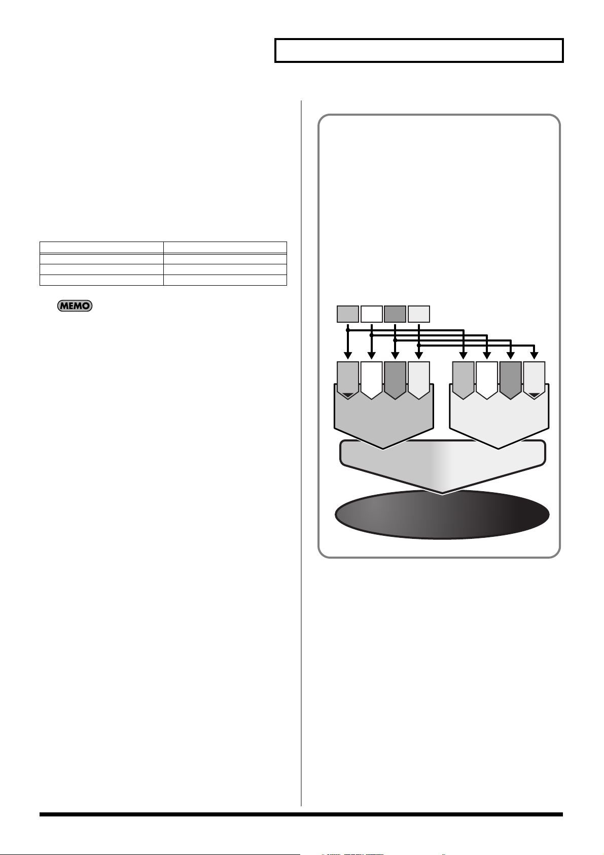
“Channels” and “Buses”
• Channel: Each of the V-440HD’s video inputs is called a
“channel.” The SD and HD/RGB sections feature Channels
1-4, with each channel being independently controlled.
Each “channel” is the equivalent of a “path” for the video
signals.
• Bus: On the V-440HD, you can select any combination of
channels to be controlled as a single group. On the V-
440HD, such a grouping of channels is referred to as a
“bus,” and the video for each bus can be selected from the
channels. The SD section features an A-BUS and B-BUS,
with the C-BUS and D-BUS included in the HD/RGB
section; in each bus you can control groupings of different
input channels.
6.
Pressing the OUTPUT FADE button again while the button is lit
or flashing causes the video output being faded out to fade back
in.
8. SD Section ...................................................................... (p. 14)
This section is used for controlling the switching, P in P, key composite,
and other functions for the video input to the SD IN inputs.
For descriptions of each button and knob, refer to SD Section (p. 14).
9. HD/RGB Section ............................................................. (p. 16)
This section is used for controlling the switching, P in P, key composite,
and other functions for the video input to the HD/RGB IN inputs.
For descriptions of each button and knob, refer to HD/RGB Section (p.
16).
Video D
Video C
Video B
Video A
Channel
Channel
Channel
Channel
1
2
4
3
A-BUS
Screen selected form Channel 1-4
Mixer
Switch / Composite A-Bus to B-Bus
Final Output
(PGM)
Channel
1
2
4
3
Channel
Channel
Channel
B-BUS
Screen selected form Channel 1-4
13
Page 14
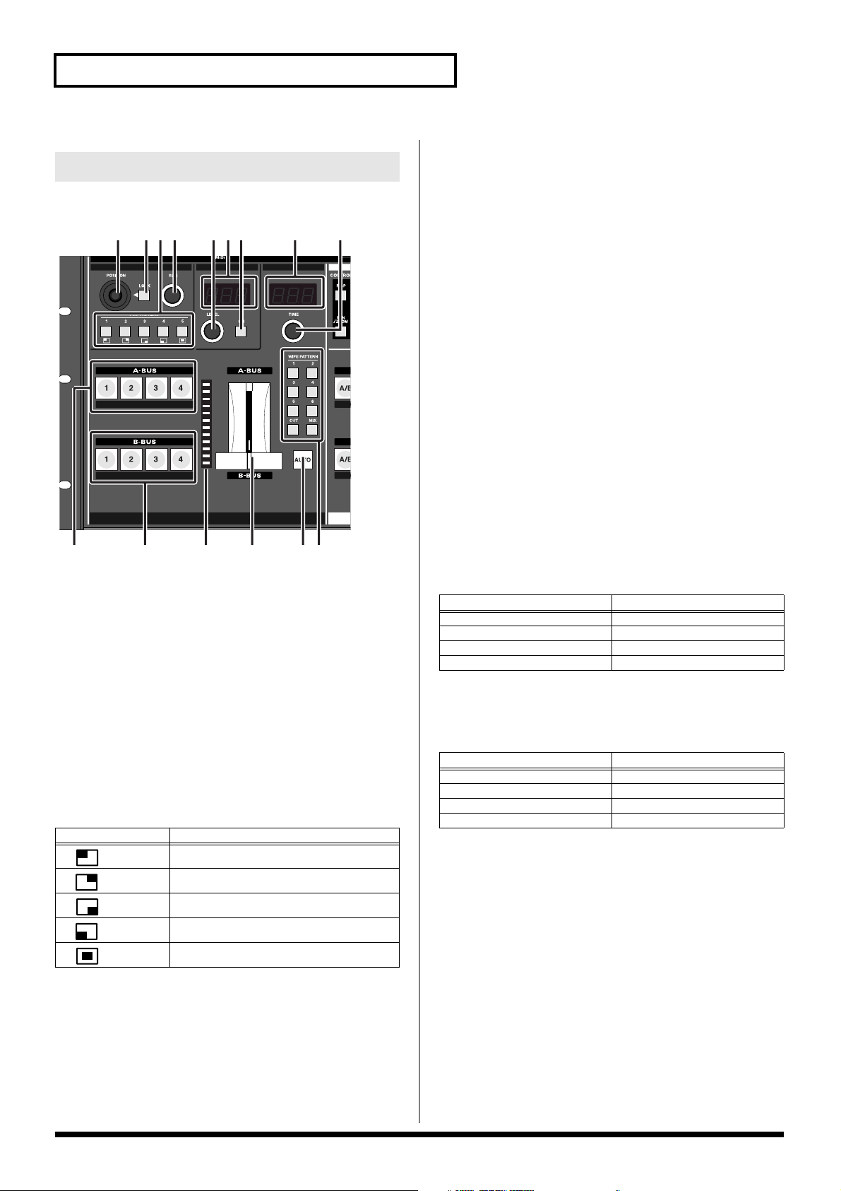
Names of Things and What They Do
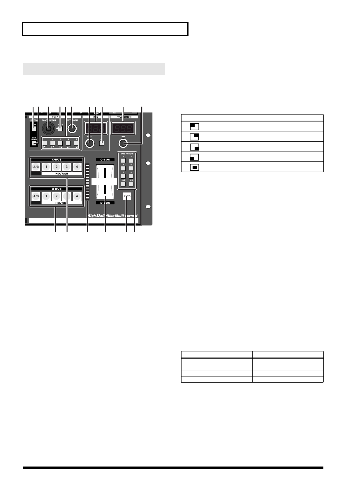
SD Section
This section is used for controlling the switching, P in P, key composite,
and other functions for the video input to the SD IN inputs.
12
34 567 8 9
10 12 13 14 1511
1. POSITION Joystick (SD) ................................................ (p. 36)
This adjusts the positioning of the small screen when the P in P effect is
used in the SD section.
The POSITION joystick (SD) can be used only when the LOCK button to
the right of the joystick is pressed to release the lock.
2. LOCK Button (SD) .......................................................... (p. 36)
When the LOCK button (SD) is lit, the P in P position cannot be changed
with the POSITION joystick (SD) to the left of the button.
Pressing the LOCK button (SD) so its light is turned off enables operation
with the POSITION joystick (SD).
3. P in P PATTERN Buttons (SD) 1-5 ................................ (p. 35)
Pressing the P in P PATTERN 1-5 buttons (SD) applies the P in P effect in
the SD section.
When the P in P effect is applied, the selected P in P PATTERN button
(SD) lights up.
Button Sub-Screen Position (Factory Setting)
1
2
3
4
5
Upper left
Upper right
Lower right
Lower left
Center
4. SIZE Knob (SD) ............................................................... (p. 36)
This adjusts the size of the small screen when the P in P effect is used in
the SD section.
5. LEVEL Knob (SD) ............................................................(p. 37)
This adjusts the key level when key composite effects are used in the SD
section.
6. LEVEL Display (SD) ........................................................(p. 37)
This indicates the value of the key level set with the (5.) LEVEL knob
(SD).
7. KEY ON Button (SD) ....................................................... (p. 37)
Pressing the KEY ON Button (SD) causes the key composite effect to be
applied in the SD section.
8. TIME Display (SD) ........................................................... (p. 34)
This indicates the transition time used to switch between the A-BUS and
B-BUS when the (14.) AUTO button (SD) is pressed. The time is indicated
in seconds.
9. TIME Knob (SD) ...............................................................(p. 34)
This sets the transition time used to switch between the A-BUS and BBUS when the (14.) AUTO button (SD) is pressed. The set time is
indicated in the TIME display. The time can be set to any value from 0.0
to 4.0.
10. A-BUS Channel Buttons (SD) 1-4 .................................. (p. 35)
These buttons are used to select the video signals to be input to the ABUS, from the video input to the SD IN connectors 1-4.
Button V-440HD Status
Lit (Yellow) Channel is selected
Lit (Green) Channel is selected (not displayed)
Off Channel selection is cancelled
Flashing (Yellow or Green) P in P or key composite is in use
11. B-BUS Channel Buttons (SD) 1-4 .................................. (p. 35)
These buttons are used to select the video signals to be input to the BBUS, from the video input to the SD IN connectors 1-4.
Button V-440HD Status
Lit (Yellow) Channel is selected
Lit (Green) Channel is selected (not displayed)
Off Channel selection is cancelled
Flashing (Yellow or Green) P in P or key composite is in use
12. TRANSITION Indicators (SD) .........................................(p. 34)
These indicate the position of the video fader.
When the AUTO button (SD) is in use, these indicate the ratio of video
being switched in the SD section. The portion of A-BUS video in the mix
increases as the position of the indicator that lights within the
TRANSITION indicators (SD) gets closer to the A-BUS, while the relative
portion of B-BUS video decreases correspondingly.
14
Page 15

13. Video Fader (SD) ............................................................ (p. 34)
Moving the video fader up or down switches between the SD section ABUS and B-BUS.
Tilt the fader shown in the figure up to switch to the A-BUS; tilt the fader
down to switch to the B-BUS. The video switches using the effect selected
with the (15.) TRANSITION buttons (SD).
14. AUTO Button (SD) .......................................................... (p. 34)
When the AUTO button (SD) is pressed, the SD section video switches
over the time indicated in the TIME display (SD).
The video switches using the effect selected with the (15.) TRANSITION
buttons (SD).
15. TRANSITION Buttons (SD) ............................................. (p. 34)
These are used to select the effect applied when switching the SD section
video with the video fader (SD) or the AUTO button (SD).
Button Function Description
CUT Cut The SD video switches when the
MIX Dissolve The SD video is mixed as it gradu-
WIPE
PATTERN
1-6
Wipe switching The SD video switches with a
SD video fader reaches the halfway point.
ally switches according to the angle of the SD video fader.
wipe effect, with the wipe corresponding to the angle of the SD
fader.
Names of Things and What They Do
15
Page 16
Names of Things and What They Do
HD/RGB Section
This section is used for controlling the switching, P in P, key composite,
and other functions for the video input to the HD/RGB inputs.
34
21
56 78 9 10 11
13
14 15 16 1712
1. P in P Button (HD/RGB) ................................................. (p. 31)
When this button is lit, the position of the subscreen when the P in P effect is
used in the HD/RGB section can be set with the POSITION joystick (HD/
RGB), while the subscreen size can be set with the SIZE/ZOOM knob (HD/
RGB).
2. PAN/ZOOM Button (HD/RGB) ....................................... (p. 31)
When using the P in P effect in the HD/RGB section, the crop position
and zoom ratio of the small screen can be set with the POSITION/PAN
joystick (HD/RGB) and SIZE/ZOOM knob (HD/RGB) knob when this
button is lit.
3. POSITION/PAN Joystick (HD/RGB) .............................. (p. 31)
This adjusts the position of, and zoom for the small screen when the P in
P effect is used in the HD/RGB section.
The POSITION/PAN joystick (HD/RGB) can be used only when the
LOCK button to the right of the POSITION/PAN joystick (HD/RGB) is
pressed to release the lock.
4. LOCK Button (HD/RGB) ................................................. (p. 31)
When the LOCK button (HD/RGB) is lit, neither the position nor panning of
the P in P subscreen be changed with the POSITION/PAN joystick (
Pressing the LOCK button (HD/RGB) so enables operation with the
POSITION/PAN joystick (HD/RGB).
HD/RGB
5. P in P PATTERN Buttons (HD/RGB) 1-5 .......................(p. 30)
Pressing the P in P PATTERN 1-5 buttons (HD/RGB) applies the P in P
effect in the HD/RGB section.
When the P in P effect is applied, the selected P in P PATTERN button
(HD/RGB) lights up.
Button Sub-Screen Position (Factory Setting)
1
2
3
4
5
Upper left
Upper right
Lower right
Lower left
Center
6. SIZE/ZOOM Knob (HD/RGB) ..........................................(p. 31)
This adjusts the size of the small screen when the P in P effect is used in
the HD/RGB section.
7. LEVEL Knob (HD/RGB) ..................................................(p. 33)
This adjusts the key level when key composite effects are used in the
HD/RGB section.
8. LEVEL Display (HD/RGB)............................................... (p. 33)
This indicates the value of the key level set with the (7.) LEVEL knob
(HD/RGB).
9. KEY ON Button (HD/RGB) .............................................. (p. 32)
Pressing the KEY ON Button (HD/RGB) causes the key composite effect
to be applied in the HD/RGB section.
10. TIME Display (HD/RGB) ..................................................(p. 28)
This indicates the transition time used to switch between the C-BUS and
D-BUS when the (16.) AUTO button (HD/RGB) is pressed. The time is
indicated in seconds.
11. TIME Knob (HD/RGB) .....................................................(p. 28)
This sets the transition time used to switch between the C-BUS and DBUS when the (16.) AUTO button (HD/RGB) is pressed. The set time is
indicated in the TIME display. The time can be set to any value from 0.0
to 4.0.
12. C-BUS Channel Buttons (HD/RGB) A/B, 1-4................. (p. 29)
These buttons are used to select the video signals to be input to the CBUS, either from the video input to the HD/RGB IN connectors 1-4 or the
final output from the SD section (SD PGM video).
Button V-440HD Status
).
Lit (Yellow) Channel is selected
Lit (Green) Channel is selected (not displayed)
Off Channel selection is cancelled
Flashing (Yellow or Green) P in P or key composite is in use
16
Page 17
13. D-BUS Channel Buttons (HD/RGB) A/B, 1-4 ................ (p. 29)
These buttons are used to select the video signals to be input to the DBUS, either from the video input to the HD/RGB IN connectors 1-4 or the
final output from the SD section (SD PGM video).
Button V-440HD Status
Lit (Yellow) Channel is selected
Lit (Green) Channel is selected (not displayed)
Off Channel selection is cancelled
Flashing (Yellow or Green) P in P or key composite is in use
14. TRANSITION Indicators (HD/RGB) ............................... (p. 28)
These indicate the position of the video fader.
When the AUTO button (HD/RGB) is in use, these indicate the ratio of
video being switched in the HD/RGB section. The portion of C-BUS
video in the mix increases as the position of the indicator that lights
within the TRANSITION indicators (HD/RGB) gets closer to the C-BUS,
while the relative portion of D-BUS video decreases correspondingly.
15. Video Fader (HD/RGB) ................................................... (p. 28)
Moving the video fader up or down switches between the C-BUS and DBUS of the HD/RGB section.
Tilt the fader shown in the figure up to switch to the C-BUS; tilt the fader
down to switch to the D-BUS. The video switches using the effect selected
with the (17.) TRANSITION buttons (HD/RGB).
16. AUTO Button (HD/RGB) ................................................. (p. 28)
When the AUTO (HD/RGB) button is pressed, the HD/RGB section
video switches over the time indicated in the TIME display (HD/RGB).
The video switches using the effect selected with the (17.) TRANSITION
buttons (HD/RGB).
17. TRANSITION Buttons (HD/RGB) ................................... (p. 28)
These are used to select the effect applied when switching the HD/RGB
section video with the video fader (HD/RGB) or the AUTO button (HD/
RGB).
Names of Things and What They Do
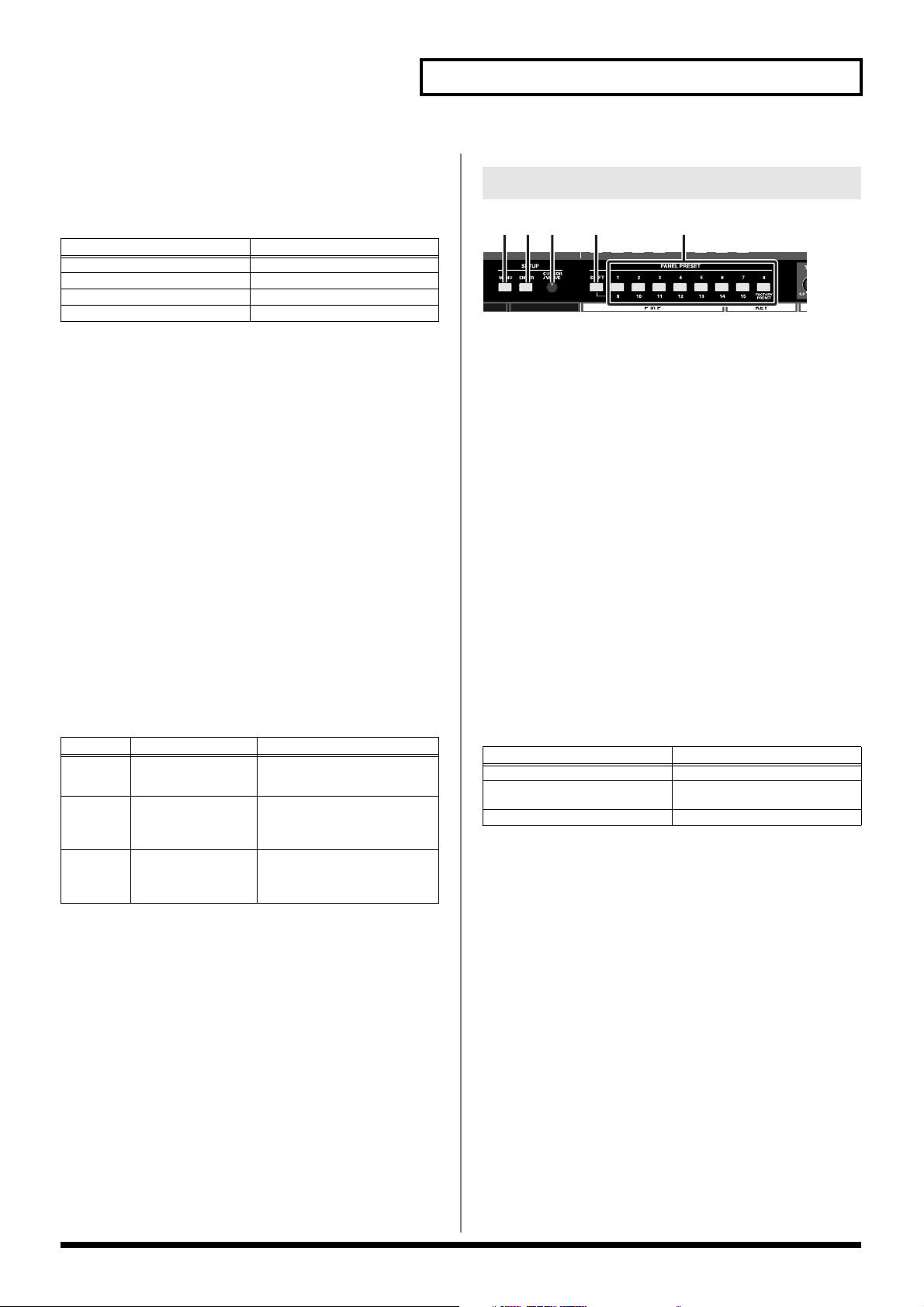
Settings Section
123 4 5
1. MENU Button ...................................................................(p. 24)
Pressing the MENU button displays the menu in the video monitor
connected to the SD PREVIEW OUT connector.
Rotate the VALUE knob to select the parameter to be set, then press the
ENTER button to enter the selection.
Pressing the MENU button while the menu is displayed closes the menu.
When the menu is appeared, the MENU button Flashing. When the
menu is disappeared, the MENU button Off.
2. ENTER Button ................................................................. (p. 24)
This is used to confirm a menu choice. The button flashes while the menu
is displayed.
3. VALUE Knob ................................................................... (p. 24)
This is used to select parameters from the menu.
4. SHIFT Button................................................................... (p. 38)
Pressing the SHIFT button so it’s lit enables selection of PANEL PRESET
9-15 using the PANEL PRESET buttons (1-8).
5. PANEL PRESET Buttons 1-8 ......................................... (p. 38)
You can store up to 15 separate configurations of parameter settings set
in each of the top sections.
You can call up the saved settings by pressing the PANEL PRESET
buttons.
PANEL PRESET 9-15 and FACTORY RESET can be selected when the
SHIFT button is lit.
Button Function Description
CUT Cut The HD/RGB video switches
MIX Dissolve The HD/RGB video is mixed as it
WIPE
PATTERN
1-6
Wipe switching The HD/RGB video switches with
when the HD/RGB video fader
reaches the half-way point.
gradually switches according to
the angle of the HD/RGB video
fader.
a wipe effect, with the wipe corresponding to the angle of the HD/
RGB fader.
Button V-440HD Function
Lit (Green) Selects PANEL PRESET 1-8
Lit (Red) Selects PANEL PRESET 9-15, FAC-
TORY RESET
Off No PANEL PRESET selected
17
Page 18
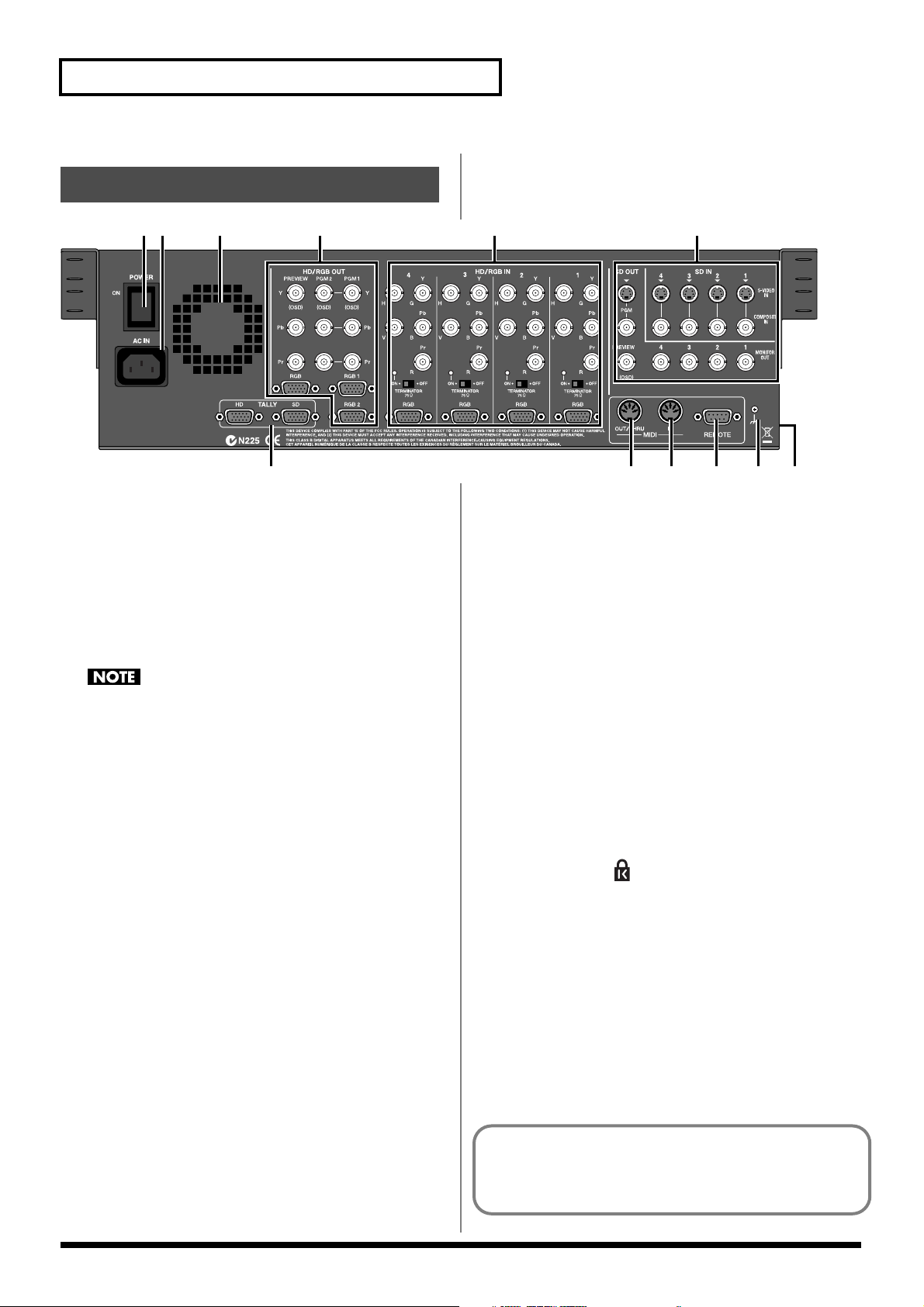
Names of Things and What They Do
Rear Panel
1
23 4 5 6
7
1. POWER Switch ............................................................... (p. 23)
This switches the V-440HD’s power on and off.
If you need to turn off the power completely, first turn off the POWER
945
switch, then unplug the power cord from the power outlet. Refer to
Turning Off the Power (p. 23).
2. AC Inlet ........................................................................... (p. 20)
Connect the power cord included with the V-440HD here.
3. Exhaust Vent .................................................................. (p. 22)
Heat generated by the V-440HD is expelled here.
Allowing this section of the panel to be blocked may, due to the
buildup of excess heat, result in damage to the V-440HD.
4. HD/RGB Output Section ................................................. (p. 19)
Video in HD or RGB format is output here. For descriptions of each
connector, refer to p. 19.
5. HD/RGB Input Section ................................................... (p. 19)
Four channels of HD or RGB video can be input using the BNC or D-sub
connectors. BNC and D-sub terminals not used for signal input can be
used as THRU outs. For descriptions of each connector, refer to p. 19.
6. SD Input/Output Section ............................................... (p. 19)
Four channels of SD video can be input using the composite video or Svideo connectors. For descriptions of each connector, refer to p. 19.
7. TALLY Terminals (HD, SD) ............................................ (p. 44)
TALLY signals are output here. When a television monitor equipped
with a TALLY terminal is connected to the V-440HD, the V-440HD can
then be used to activate the television monitor's TALLY lamp.
Tally signals from the HD/RGB section are output from the TALLY HD
terminal; tally signals from the SD section are output from the TALLY SD
terminal. For descriptions of each terminals, refer to p. 44.
8. MIDI OUT/THRU ............................................................. (p. 45)
Use this connector to connect the V-440HD to an external MIDI device
and transmit MIDI messages to the other MIDI device. Use a MIDI cable
(sold separately) to connect the devices. You can also use this connector
as a THRU output for MIDI signals received at the MIDI IN connector.
9. MIDI IN Connector .......................................................... (p. 45)
Use this connector to connect the V-440HD to an external MIDI device
and receive MIDI messages from the other MIDI device. Use a MIDI cable
(sold separately) to connect the devices.
9810
10. REMOTE Connector ...................................................... (p. 44)
Use this connector when using serial control from computers or other
external devices.
Refer to the chart of serial signals on p. 44.
11. Ground terminal
Depending on the circumstances of a particular setup, you may
927
experience a discomforting sensation, or perceive that the surface feels
gritty to the touch when you touch this device, microphones connected to
it, or the metal portions of other objects, such as guitars. This is due to an
infinitesimal electrical charge, which is absolutely harmless. However, if
you are concerned about this, connect the ground terminal (see figure)
with an external ground. When the unit is grounded, a slight hum may
occur, depending on the particulars of your installation. If you are unsure
of the connection method, contact the nearest Roland Service Center, or
an authorized Roland distributor, as listed on the “Information” page.
Unsuitable places for connection
• Water pipes (may result in shock or electrocution)
• Gas pipes (may result in fire or explosion)
• Telephone-line ground or lightning rod (may be dangerous in
the event of lightning)
988
12. SECURITY Slot ( )
http://www.kensington.com/
11 12
About the Preview Screen
The V-440HD's "Preview OUT" outputs video from the bus not being
used to output from PGM OUT.
18
Page 19
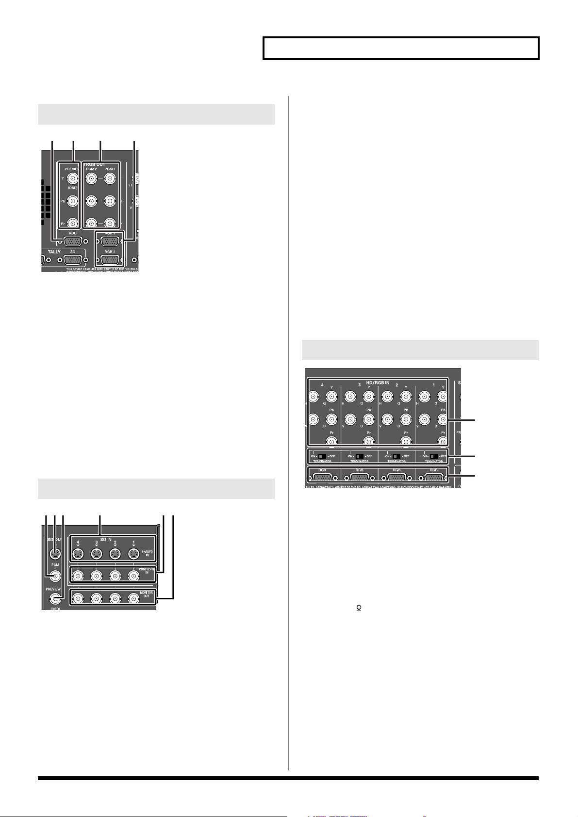
HD Output Section
321 4
1. RGB PREVIEW Connector (Analog RGB) .................... (p. 20)
The HD/RGB bus preview screen is output in RGB (analog/D-Sub) from
this connector.
* The video in the HD/RGB Preview screen is displayed with the P in P
effect (p. 30) and other such effects applied.
2. HD PREVIEW Connectors (Analog Component)......... (p. 20)
This is a BNC connector for outputting the HD/RGB bus preview screen
as analog component video.
* The video in the HD/RGB Preview screen is displayed with the P in P
effect (p. 30) and other such effects applied.
3. HD OUT 1, 2 Connectors (Analog Component)........... (p. 20)
These are BNC connectors for outputting the video combined on the
HD/RGB bus as analog component video.
4. RGB OUT 1, 2 Connectors (Analog RGB) .......... (p. 20, p. 43)
The composite video from the HD/RGB bus is output as RGB signals
from this connector.
SD Input/Output Section
456321
Names of Things and What They Do
4. SD S-VIDEO IN 1-4 Connectors .......................... (p. 20, p. 27)
These are connectors for input of S-Video to SD buses 1-4.
Video devices equipped with an S-Video output connector can be
connected here.As initially set at the factory, when video is
simultaneously being input to the SD COMPOSITE IN connector for the
same channel, the video input to the SD S-VIDEO IN connector is given
priority.
5. SD COMPOSITE IN 1-4 Connectors (Analog) .... (p. 20, p. 27)
These are connectors for input of composite video to SD buses 1-4.
Video devices equipped with a composite video output connector can be
connected here.
As initially set at the factory, when video is simultaneously being input to
the SD S-VIDEO IN connector for the same channel, the video input to
the SD S-VIDEO IN connector is given priority.
* You can set the V-440HD so that the SD COMPOSITE IN connectors the
SD S-VIDEO IN connectors. To make this setting, go to "7. SD Input" (p.
51) - "1. SD Input Select" in the menu, then select "Composite."
6.
SD MONITOR OUT Output 1-4 Connectors (Analog Composite Video)
These BNC connectors output video from the SD S-VIDEO IN connectors or SD
COMPOSITE IN connectors as composite video.
When the V-440HD is connected to a video monitor equipped with composite
video input connectors, you can monitor the video of each channel.
...(p. 20)
HD/RGB Input Section
1
2
3
1.
HD/RGB IN 1-4 Connectors (Analog Component/RGB) .. (
These are BNC connectors capable of being used for input of analog
component signals or RGB signals.
If not inputting video, connectors to which no video is being input can be
used as loop thru outputs for video input via the HD/RGB IN 1-4
connectors (analog RGB).
* Video cannot be input via both the HD/RGB IN (BNC) connectors and
IN (D-Sub) connectors simultaneously. Inputting video simultaneously
in this manner may result in disruption of the video images.
p. 20
)
1. SD PGM OUT COMPOSITE Connector (Analog) ......... (p. 20)
This connector outputs composite effects from the SD section as
composite video signals. Video monitors equipped with a composite
video input connector can be connected here.
2. SD PGM OUT S-VIDEO Connector ............................... (p. 20)
This Connector outputs composite effects from the SD bus as S-video
signals. Video monitors equipped with an S-Video input connector can be
connected here.
3. SD PREVIEW OUT Connector ............................. (p. 20, p. 24)
The preview screen from the SD Section is output from this connector.
The menu (p. 24) is also displayed.
* The video in the SD Preview screen is displayed without the P in P
effect (p. 35) and other such effects applied.
2. ............................(p. 21)
HD/RGB 75 TERMINATOR 1-4 Switches
Switch to ON if no cables are connected to either the HD/RGB IN (BNC)
connectors or the HD/RGB IN (D-Sub) connector.
Switch to OFF if using these connectors as loop thru connectors.
3.
HD/RGB IN 1-4 Connectors (RGB/Analog Component) .. (
These are D-Sub connectors capable of being used for input of analog
component signals or RGB signals.
If not inputting video, connectors to which no video is being input can be
used as loop thru outputs for video input via the HD/RGB IN 1-4
connectors (analog component).
* Video cannot be input via both the HD/RGB IN (BNC) connectors and
IN (D-Sub) connectors simultaneously. Inputting video simultaneously
in this manner may result in disruption of the video images.
p. 20, p. 43
19
)
Page 20
Connections and Settings
Making the Connections
921
To prevent malfunction and/or damage to speakers or other devices, always turn
down the volume, and turn off the power on all devices before making any
connections.
1
Before connecting the V-440HD, make sure that the power to all devices to be
connected is turned off.
2
Connect the included power cord to the V-440HD’s AC inlet, then connect the
other end of the cord to a power outlet.
3
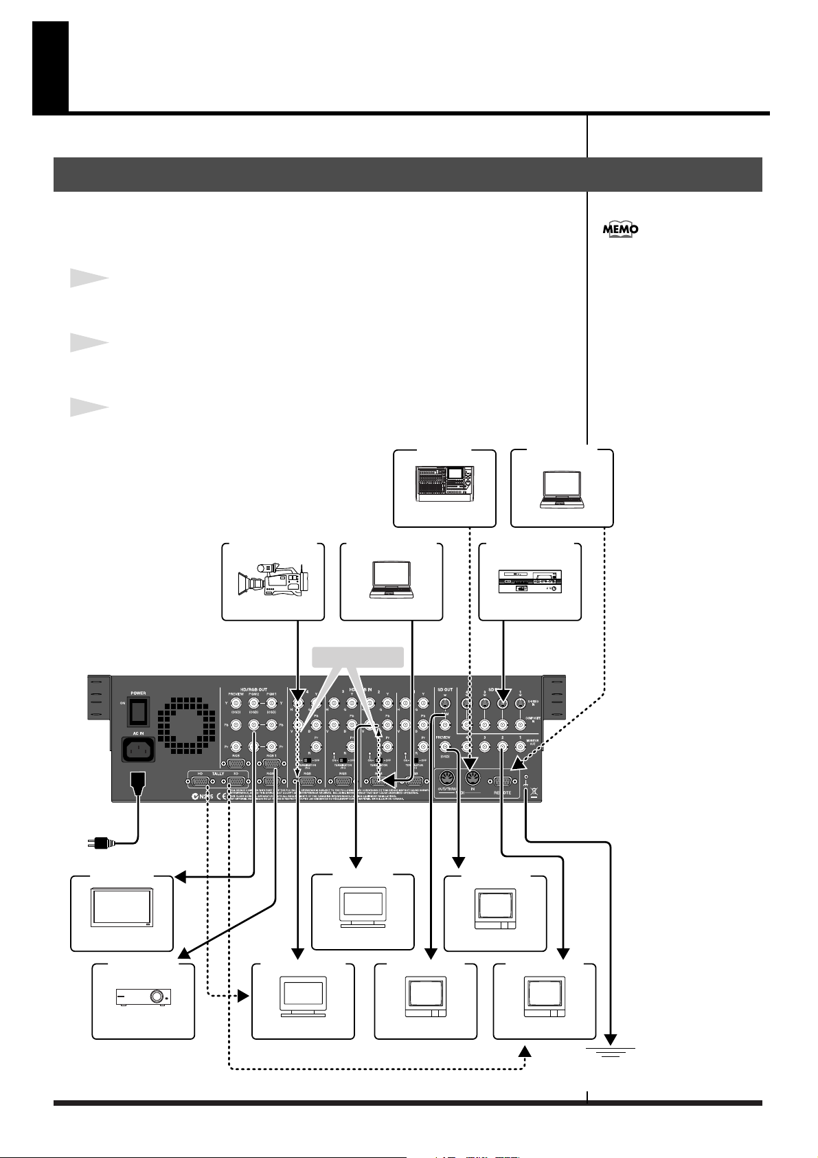
Connect the V-440HD to other devices as shown in the figure.
[V-440HD Connecting Diagram]
HD Video Output Device
MIDI Device
MIDI Sequencer
RGB Video Output Device
MIDI Cable
SD Video Output Device
HD/RGB IN Connectors
(Analog Component/RGB)
Make sure that the component Y, Pb,
and Pr are properly connected when
connecting component video to the
HD/RGB IN BNC connectors. If
connecting RGB video, connect R, G,
B, H, and V. Failure to connect these
properly may prevent output of the
video or result in problems with the
colors.
RS-232C Device
PC or Other Device
RS-232C Cable
AC Cable
to Concent
Final Output (HD)
Plasma Display or Other Display
Final Output (RGB)
HD Camera
D-Sub Cable
D-Sub Cable
Component
Cable
Component-D-Sub Cable
VGA Cable
Component Cable
HD IN Monitor
PC or Other Device
Loop Thru
Component-
D-Sub Cable
VGA Monitor
VGA Display
D-Sub Cable
Composite Cable
TV Monitor or Other Device
SD PGM OUT Monitor
DV Camcoder , Presenter
Composite
Cable
Composite
Cable
SD PREVIEW Monitor
Ground terminal
SD IN Monitor
Composite Cable
20
Projector or Other Display
Multiformat Monitor or Other Device
TV Monitor or Other Device
TV Monitor or Other Device
external ground
Page 21

About Loop Thru
The HD/RGB IN connector (D-sub) and HD/RGB IN connector (BNC) for any
particular channel are linked internally within the unit. So, for example, if analog
component signals are input to the Channel 1 HD/RGB IN connector (D-sub), the
same signals are output from the Channel 1 HD/RGB IN connector (BNC). This
function is called "Loop Thru."
Using Loop Thru, you can monitor the video output of each video input on a
television monitor, or even use the connections for multiscreen output.
However, the following precautions must be observed.
• Set the TERMINATOR 75Ω switch to ON when Loop Thru is not being used
Some devices may not function properly when Loop Thru is not in use unless the
TERMINATOR 75Ω switch is set to ON.
• Using more than one pass with Loop Thru may result in attenuation of the video
With three or more V-440HDs connected using Loop Thru, the video signal becomes
more attenuated the further down the signal path the V-440HD is.
When using identical video with three or more V-440HDs, be sure to use a
commercially available video multiplexer.
Connections and Settings
21
Page 22
Connections and Settings
Precautions When Making Settings
The V-440HD is force cooled, using a cooling
fan to dissipate high interior temperatures.
Exterior air is drawn through the front panel
intake vent and expelled from the rear panel
exhaust vent (see figure).
• Use a vacuum cleaner or other means to
remove any dust that may accumulate in the
intake and exhaust vents.
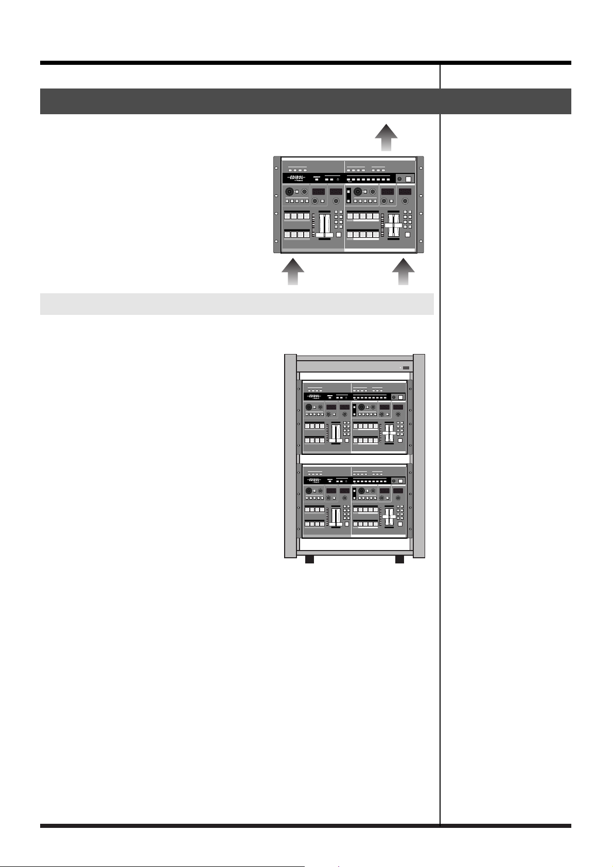
With Rack-Mounting and Other Enclosures
Observe the following precautions when mounting the V-440HD in a rack or
portable case.
• Ensure that the location provides good air
flow.
• If the rack’s rear panel is not removable, ensure
that there is a minimum of 10 cm clearance
between the V-440HD’s exhaust vent and the
rack’s rear panel, and that the top of the rack
has a ventilation port or exhaust fan to expel
any accumulated heat.
• If mounted in a portable case, ensure that the
intake vent is not obstructed.
• Use due caution when mounting the V-440HD
in a rack or other enclosure so your fingers
don’t get wedged or pinched between the V440HD and the rack or enclosure.
22
Page 23
Basic Operation
Turning On the Power
941
• Once the connections have been completed (p. 20), turn on
power to your various devices in the order specified. By turning
on devices in the wrong order, you risk causing malfunction
and/or damage to speakers and other devices.
942
• This unit is equipped with a protection circuit. A brief interval
(a few seconds) after power up is required before the unit will
operate normally.
1. Before turning on the power, confirm that all other devices
are properly connected.
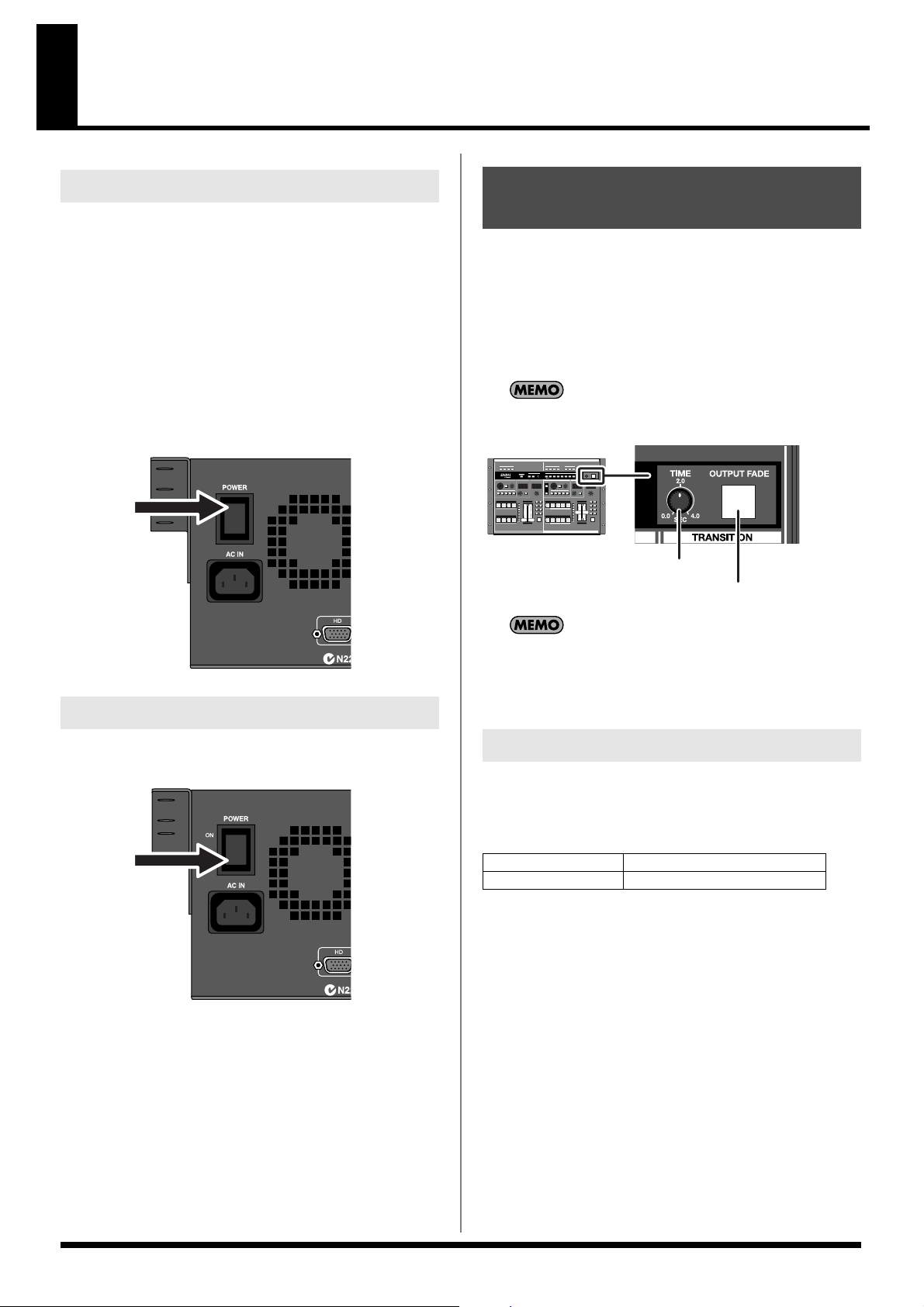
2. Switch the POWER switch on the V-440HD’s rear panel to
ON.
Outputting and Stopping the Final Output
To output and stop the V-440HD's final output, use the OUTPUT
FADE button.
You can have the final output fade out over the period set with the
TIME knob by pressing the OUTPUT FADE button. This period can
be set from 0.0 seconds to 4.0 seconds. Pressing the OUTPUT FADE
button after the final output has faded out causes the video to fade in
again.
If you are not going to fade the final output in or out, set the
TIME knob to 0.0.
TIME Knob
OUTPUT FADE Button
Turning Off the Power
1. Switch the POWER switch on the V-440HD’s rear panel to
OFF.
945
If you need to turn off the power completely, first turn off the
POWER switch, then unplug the power cord from the power outlet.
Making the Connections (p. 20).
Refer to
When the OUTPUT FADE button is pressed while a fade-out or
fade-in is in progress, the fade-out or fade-in stops at that point.
Pressing the OUTPUT FADE button once more starts the fade-
out or fade-in again.
Making the Fade-out Settings
Make the fade-out settings with the "12. Output Fade Mode" and "13.
Output Fade Color " settings under "1. HD/RGB Output " in the
menu (p. 24).
Output Fade Mode Sets the final output fade control
Output Fade Color Sets the final output fade color
* For more on the menu, refer to "Menu Operations" (p. 25).
* You can move the cursor to the "12. Output Fade Mode" parameter
under "1. HD/RGB Output" in the menu by holding down the
MENU button and pressing the OUTPUT FADE button.
23
Page 24
Basic Operation
Making Various Settings
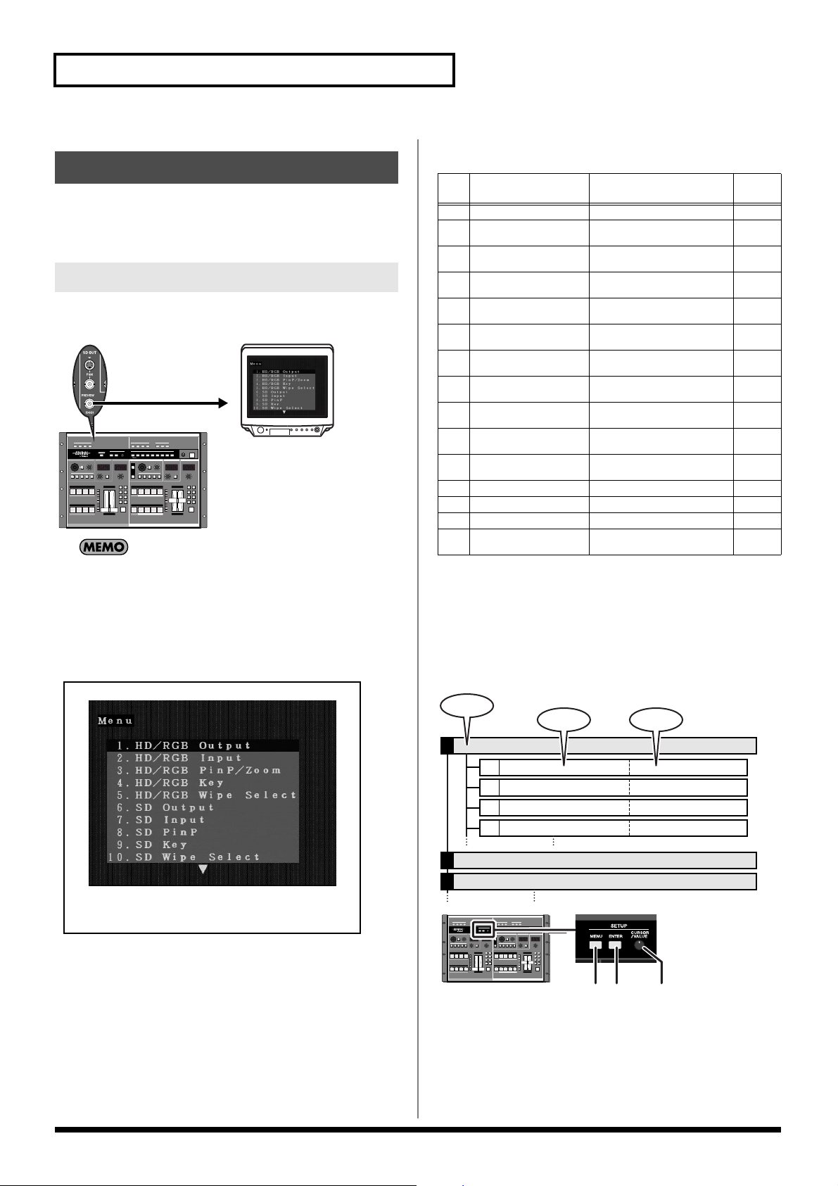
The V-440HD’s various settings are set from the menu. The menu is
displayed on the video monitor connected to the SD PREVIEW OUT
connector.
Displaying Menus
Press the MENU button to display the menu on the video monitor
connected to the SD PREVIEW OUT connector.
TV Monitor
By holding down the SHIFT button and pressing the MENU
button, you can display the video output from the HD OUT
connectors and HD PREVIEW OUT connectors, or from the
RGB OUT connectors and RGB PREVIEW OUT connectors in
the menu.
* This is a shortcut for switching the "11. HD On Screen Display"
function in "13. System" (p. 54) on and off.
Parameters Shown
in Menu
HD/RGB Output
1
HD/RGB Input
2
HD/RGB PinP/Zoom
3
HD/RGB Key
4
HD/RGB Wipe Select
5
SD Output
6
SD Input
7
SD PinP
8
SD Key
9
SD Wipe Select
10
Panel Preset Edit
11
Multi Screen
12
System
13
MIDI Setup
14
Factory Reset
15
Notes
Related
Page
Settings for the final output
Settings for the input from the HD/
RGB IN connectors
Advanced settings for the HD/RGB
section’s P in P effect
Advanced settings for the HD/RGB
section’s key composite effects
Settings for the TRANSITION buttons’ (HD/RGB) WIPE PATTERN 1-6
Settings for the SD section’s output
are made here
Settings for the input from the SD IN
connectors
Advanced settings for the SD section’s P in P effect
Advanced settings for the SD section’s key composite effects
Settings for the TRANSITION buttons’ (SD) WIPE PATTERN 1-6
These settings are used to copy and
exchange panel presets
Settings for the Multi Screen output
The V-440HD’s system settings
MIDI-related settings
This restores the V-440HD to its
original factory default settings.
P.48
P.49
P.50
P.50
P.51
P.51
P.51
P.52
P.52
P.52
P.53
P.53
P.54
P.55
P.55
About the Menu Hierarchy
The V-440HD’s menu comprises three different levels, as shown in
the figure below. The lowest level is where numerical values and
other parameter values are selected.
Press the ENTER button to go to a lower level in the menu. Press the
MENU button to move up a level.
Menu
Parameter
HD/RGB Output1.
1-3:
1-3:
HD/RGB Input2.
HD/RGB PinP/Zoom3.
Parameter Value
Output Format (1080) Sw1-1:
Output Format (1080) Sw1-2:
Output Format (1080) Sw
Output Format Sw Lock
MENU
Button
1280x1024, 1280x768, ....
1280x1024, 1280x768, ....
1280x1024, 1280x768, ....
On, Off
VALUE
ENTER
Button
Knob
Closing the Menu
To close the menu, press the MENU button while the topmost level
is displayed.
24
Page 25

Basic Operation
Menu Operations
Moving the Cursor and Selecting
Rotate the VALUE knob to move the cursor up and down. The
parameter at the cursor position flashes, indicating that the
parameter can be selected. When selecting numerical or other
parameter values, change the value at the cursor position.
MENU
Button
ENTER
Button
VALUE
Knob
Confirming Parameter Selections
Move the cursor to the desired parameter, and confirm selection of
the parameter by pressing the ENTER button. When the parameter is
selected, the cursor shifts to the next lower line.
MENU
Button
ENTER
Button
VALUE
Knob
Saving Settings Selected in the
Menu
Shortcuts to the Menu Parameters
You can easily open parameters corresponding to buttons in the
menu by holding down the MENU button and pressing the button
for the corresponding settings parameter.
Operation of the parameter indicated with the shortcut is the same as
in the normal menu.
Shortcuts are used with the following buttons.
Button name
SD IN Button 1 - 4
HD/RGB IN Button1 - 4
OUTPUT FORMAT Button
OUTPUT FADE Button
P in P PATTERN Button (SD) 1 - 5
P in P PATTERN Button (HD/
RGB) 1 - 5
KEY ON Button (SD)
KEY ON Button (HD/RGB)
TRANSITION Button (SD)
* WIPE PATTEN1 - 6
TRANSITION Button (HD/RGB)
* WIPE PATTEN1 - 6
SHIFT Button * See p.24 p.24
Parameter displayed by Shortcut
7. SD Input
2. HD/RGB Input
1. HD/RGB Output
1. HD/RGB Output
8. SD PinP
3. HD/RGB PinP/Zoom
(p. 50)
9. SD Key
4. HD/RGB Key
10. SD Wipe Select
52)
5. HD/RGB Wipe Select
(p. 51)
(p. 51)
(p. 49)
(p. 48)
(p. 48)
(p. 52)
(p. 52)
(p. 50)
(p.
Related
Page
p.27
p.27
p.26
p.23
p.35
p.30
p.37
p.32
p.34
p.28
Settings are saved in the V-440HD’s internal memory by pressing the
MENU button a number of times until the menu is closed.
25
Page 26

Input and Output Settings
Since the V-440HD is capable of handling video input and output
with entirely different formats, it may be necessary to make
adjustments for the differences in picture quality and angle of view
in each video format. To match the device used for inputting video
to the V-440HD to the device receiving the output from the V-
440HD, make the input and output settings.
Selecting the Output Format
Making the Output Settings
The output settings are made from the menu. The menu is displayed
in the SD video output from the SD PREVIEW OUT connector.
* For more on the menus, refer to Menu Operations (p. 25).
* To rapidly get to the output settings menu, hold down the MENU
button and press one of the OUTPUT FORMAT buttons.
Press an OUTPUT FORMAT button to select the format for the video
output from the HD OUT connectors (p. 19) or RGB OUT connectors
(p. 19). The selected button lights up.
Button Output Format
(Factory Default
Setting)
1080i 1080/60i HD OUT Connectors 1, 2 (not
720p 720/60p HD OUT Connectors 1, 2 (not
RGB 1024x768/60 RGB OUT Connectors 1, 2
* The formats shown above are the default factory settings. You can also
select output formats other than these. For more details, refer to
About the Final Output Format (p. 48).
Output Connectors
(Factory Preset Setting)
output from RGB OUT connectors 1, 2)
output from RGB OUT connectors 1, 2)
(not output from HD OUT
connectors 1, 2)
Start with the Output Settings
When making these settings, start by making the output
settings first. Setting the output after making the input settings
will result in discrepancies in the color and angle of view if the
input video is switched to a format other than those used in the
output settings.
1. HD/RGB Output Settings Parameters
Output Format (1080i ) Sw (1080i) video format
Output Format (720p) Sw (720p) video format
Output Format (RGB) Sw (RGB) video format
Output Format Sw Lock OUTPUT FORMAT button lock
Zooming Final output scaling adjustment
Bright Final output brightness adjustment
Contrast Final output contrast adjustment
Saturation Final output saturation adjustment
Red Final output red adjustment
Green Final output green adjustment
Blue Final output blue adjustment
Output Fade Mode Final output fade control adjustment
Output Fade Color Final output fade color setting
Test Pattern Select Test pattern output
About the Output Format
The V-440HD handles output in the following formats
[HD OUT]
The HD output formats feature frame rate settings of 60 and 50. The
frame rate used in the United States and Japan (NTSC regions) is 60;
in Europe (PAL regions), the frame rate is 50. The frame rate can be
switched using the procedure described on p. 42.
60 - NTSC 50 - PAL
1080/60i 1080/50i
720/60p 720/50p
480/60p 576/50p
480/60i 576/50i
[RGB OUT]
1280x1024/60 1024x768/60 640x480/75
1280x1024/60 1024x768/75 640x480/60
1280x768/75 800x600/75
1280x768/60 800x600/60
* Units: [horizontal (pixels) x vertical (lines) / frame rate (Hertz)].
About Delayed Output
Note that, due to the process of up-converting and down-
converting processes, the use of multiple formats with the V-
440HD will result in a lag of several frames.
[Approximate Delays]
Input/Output SD PGM Out
SD Input 1 frame 2 frames
HD/RGB Input --- 1 frame
These delays may cause discrepancies in the timing of the
external audio and the video processed by the V-440HD. In
such a case you might use an audio delay line in order to
synchronize the video and audio.
26
HD Out / RGB Out
About NTSC and PAL SD Output
Either NTSC or PAL can be selected for the SD section's input and
output. For instructions on making the settings, refer to Switching
Between NTSC and PAL (p. 42). Additionally, the HD OUT output
format frame rate is determined by the format set here.
Page 27

Input and Output Settings
Setting the HD/RGB Input
With the HD/RGB inputs, the image’s dimensions and color may
vary with each individual format and/or device, so it may be
necessary to make separate settings for each input individually.
The default factory setting for the HD/RGB input format is
“AUTO,” whereby the settings are determined automatically.
Settings
Make the HD/RGB video settings with "2. HD/RGB Input" in the
menu. With "2. HD/RGB Input," you can select from the HD/RGB
Channel A/B and 1-4, and set the following parameters.
* To quickly go to the input settings menu, hold the MENU button and
Press any of the HD/RGB Buttons 1-4.
* For more on the menus, refer to Menu Operations (p. 25).
2. HD/RGB Input Settings Parameters
Format Auto Detect Function automatically distinguishes input
Input Format Input format select
Pre Scaling Mode Switches scaling adjustment function on and off
Manual Pre Scaling Adjusts scaling ratio when full scaling used
Scaling Type Scaling method
Manual X Scale Adjusts the horizontal expansion ratio
Manual Y Scale Adjusts the vertical expansion ratio
X Position Fine adjustment of the horizontal start position
Y Position Fine adjustment of the vertical start position
Brightness Brightness adjustment
Contrast Contrast adjustment
Saturation Saturation adjustment
Red Red adjustment
Green Green adjustment
Blue Blue adjustment
Frequency Fine adjustment of the Sampling Frequency
Phase Fine adjustment of the Sampling Phase
About HD Input
The V-440HD is compatible with the following HD signal formats.
• 1080 59.94i / 50i : (SMPTE 274M)
• 720 59.94p / 50p : (SMPTE 296M)
About RGB Input
The V-440HD is compatible with the following RGB signal formats.
• 640x480 60 / 75Hz
• 800x600 60 / 75Hz
• 1024x768 60 / 70 / 75Hz
• 1280x768 60 / 75Hz
• 1280x1024 60Hz
* Units: [horizontal (pixels) x vertical (lines) / frame rate (Hertz)].
* Certain signal conditions may produce differences in the aspect ratio
and position of the RGB input. If this occurs, make adjustments with
the "X position," "Y position," "Frequency," "Phase" or other
relevant settings from the menu.
Setting the SD Input
Although the SD input is in a fixed format, there may be differences
in the type of device used or physical differences, and it may be
necessary to set each input individually.
Settings
Make the SD video settings in the menu with "7. SD Input." In "7. SD
Input," you can select from the SD Channel 1-4, and make settings
the parameters listed below.
* For more on the menus, refer to Menu Operations (p. 25).
* To quickly go to the Input settings menu, hold down the MENU
button and press any of the SD IN buttons 1-4.
7. SD Input Settings Parameters
SD InputSelect Selects S-Video or component for the SD input
SD Brightness Brightness adjustment
SD Contrast Contrast adjustment
SD Saturation Saturation adjustment
SD Hue Hue adjustment
About SD Input
The V-440HD is compatible with the following SD signal formats.
• NTSC 59.94 Hz Component video format
S-Video format
• PAL 50 Hz Component video format
S-Video format
Select either NTSC or PAL for use with the V-440HD. For
instructions on setting the SD signal format to be used, refer to
Switching Between NTSC and PAL (p. 42)
Inputting Analog Component SD Video
To input SD video to the V-440HD as analog component video,
input to the HD/RGB IN BNC connectors. In this case, the input
SD video is handled in the HD/RGB section.
With analog component input, no interlace to progressive
conversion is performed. We recommend that a progressive
signal (480p/576p) be employed for the SD video input.
27
Page 28

HD/RGB Section Operations
In the HD/RGB section, you can switch and compose HD and RGB
video and the final video output from the SD section (SD PGM
video).
Switching in the HD/RGB Section
Using the V-440HD’s video fader (HD/RGB) along with the C-BUS
channel buttons (HD/RGB) and D-BUS channel buttons (HD/RGB),
you can switch between HD, RGB, and SD video input. Each type of
video being input is indicated in the input settings (p. 27).
C-BUS Channel Button
(HD/RGB)
Video Fader
(HD/RGB)
Switching Buses with the AUTO Button (HD/
RGB)
The C-BUS and D-BUS switch automatically when the AUTO Button
(HD/RGB) is pressed. The time used for switching between the C-
BUS and D-BUS is set by rotating the TIME knob (HD/RGB). The
time set with the TIME knob (HD/RGB) is indicated in the HD/RGB
TRANSITION TIME display. The time can be set to any value from
0.0 to 4.0 sec.
Selecting the Effect Applied When Switching
D-BUS Channel Button
(HD/RGB)
Switching Buses with the Video Fader (HD/
Buses (HD/RGB)
The effect applied when switching the video is selected by pressing
the TRANSITION buttons (HD/RGB).
RGB)
Moving the video fader up or down switches between the HD/RGB
section’s C-BUS and D-BUS.
When the video fader (HD/RGB) is tilted towards the C-BUS, the
video on the C-BUS is output. Similarly, when the video fader (HD/
RGB) is tilted towards the D-BUS, the video on the D-BUS is output.
TIME Knob
(HD/RGB)
AUTO Button
(HD/RGB)
* For instructions on selecting the video on the C-BUS and D-BUS,
refer to Selecting the Bus Input (HD/RGB) (p. 29).
To confirm (preview) the video in the bus opposite that to which
the video fader (HD/RGB) is tilted, connect a television monitor
either to the "RGB PREVIEW connector (Analog RGB)" (p. 19) or
the "HD PREVIEW connector (Analog Component)" (p. 19).
As the HD/RGB section can be used to switch video in a variety
of different formats, some time may be required to lock the video
signals when switching channels with the C-BUS channel
buttons (HD/RGB) and D-BUS channel buttons (HD/RGB).
Thus, we recommend using Preview to confirm the video when
using the video fader (HD/RGB) to switch the video.
Button Function Description
CUT Cut The video switches
when the video fader
(HD/RGB) reaches
the halfway point.
MIX
WIPE PATTERN 1-6 Wipe switching The video switches
Dissolve The video is mixed as
it gradually switches
according to the angle
of the video fader
(HD/RGB).
with a wipe effect,
with the wipe corresponding to the angle
of the video fader
(HD/RGB).
*This cannot be used
when the P in P effect (p.
30) is being used. If the P
in P effect is in use when
WIPE PATTERN 1-6 is
selected, MIX is selected
automatically.
28
Page 29

Selecting the Bus Input (HD/RGB)
The video used on the C-BUS is selected by pressing the C-BUS
channel buttons (HD/RGB) 1-4 and A/B button. In the same
manner, the video used on the D-BUS is selected by pressing the D-
BUS channel buttons (HD/RGB) 1-4 and A/B button.
HD/RGB Section Operations
Customizing Wipe Transitions
The wipe switching effects assigned to the TRANSITION
(HD/RGB) WIPE PATTERN 1-6 buttons can be set from the
menu. You can make settings for the wipe pattern, direction,
and soft edge, and combine these settings in various ways to
create customized wipe transitions.
* For more on the menus, refer to Menu Operations (p. 25).
* When key composite effect (p. 32) in use, you can not use the
soft edge.
Wipe Patterns
Horizontal
When switching channels with the C-BUS channel buttons
(HD/RGB) and D-BUS channel buttons (HD/RGB), several
frames is required to switch the video in each bus. This is due to
the time required to lock the video signals when switching the
video input formats used in each channel. To shorten the
duration, select the following parameter from the menu and
adjust the parameter.
* When you need to switch between Buses quickly, use the
Video Fader (HD/RGB) (p. 28)
* With some settings, noise may occur when the video is
switched. Set a value that provides sufficient time for
switching to avoid this problem.
• "HD/RGB Input" - (Each channel)
[1. Format Auto Detect]
If "Auto" is set, set this to "Manual" and then select the
format for the video being input.
[2. Input Format]
Select the format for the video being input.
• "13. System"
[9. HD Seamless Delay Time]
Keep the time setting somewhat short. The unit of time is
the field.
Vertical
Horizontal Open
Vertical Open
Box
Cross
29
Page 30

HD/RGB Section Operations
* Use of the C-BUS channel buttons (HD/RGB) (or D-BUS channel
HD/RGB Section P in P Effects
P in P (Picture in Picture) effects are applied to the video on the C-
BUS or D-BUS. The video on the bus to which the P in P effect is
applied appears as a smaller sub-screen displayed in reduced size
over the video on the other bus.
Background
Insert
buttons (HD/RGB)) while combining video with the P in P effect may
result in disruption of the video image.
* Wipe Patterns 1-6 cannot be selected with the "TRANSITION
buttons (HD/RGB)" (p. 28) while the P in P effect is in use.
Terminology Used with the P in P Effect
The following terminology is used in describing the V-440HD’s
P in P effect.
• Position: positioning of the sub-screen
• Size: size of the sub-screen
• Zoom: Magnification of the video in the sub-screen (HD/
RGB only)
• Pan: Positioning of the video within the sub-screen (HD/
RGB only)
[Position - Size]
Procedure for Setting the HD/RGB Section P in P Effect
2, 41 3
1. Select the video to include in the sub-screen with the C-
BUS channel buttons (HD/RGB) (or D-BUS channel buttons
(HD/RGB)).
2. Tilt the video fader (HD/RGB) to the opposite side from that
of the bus selected in Step 1.
3. Press a P in P PATTERN button (HD/RGB).
The button or buttons pressed in Step 1 flash. At this point, a button
flashing indicates that the P in P effect is being applied to the video
assigned to that button.
Button Sub-Screen Position (Factory Setting)
1
2
3
4
5
Upper left
Upper right
Lower right
Lower left
Center
Position Size
[Zoom - Pan]
Zoom
Use of zoom/pan does not change the
position or size of the sub-screen.
Pan
4. Tilt the video fader (HD/RGB) to the opposite direction.
The video assigned to the channels corresponding to the flashing
buttons in Step 3 appears as the sub-screen.
* When key composite effects are in use, the P in P effect is applied to the
selected bus, regardless of the video fader (HD/RGB) position.
30
Page 31
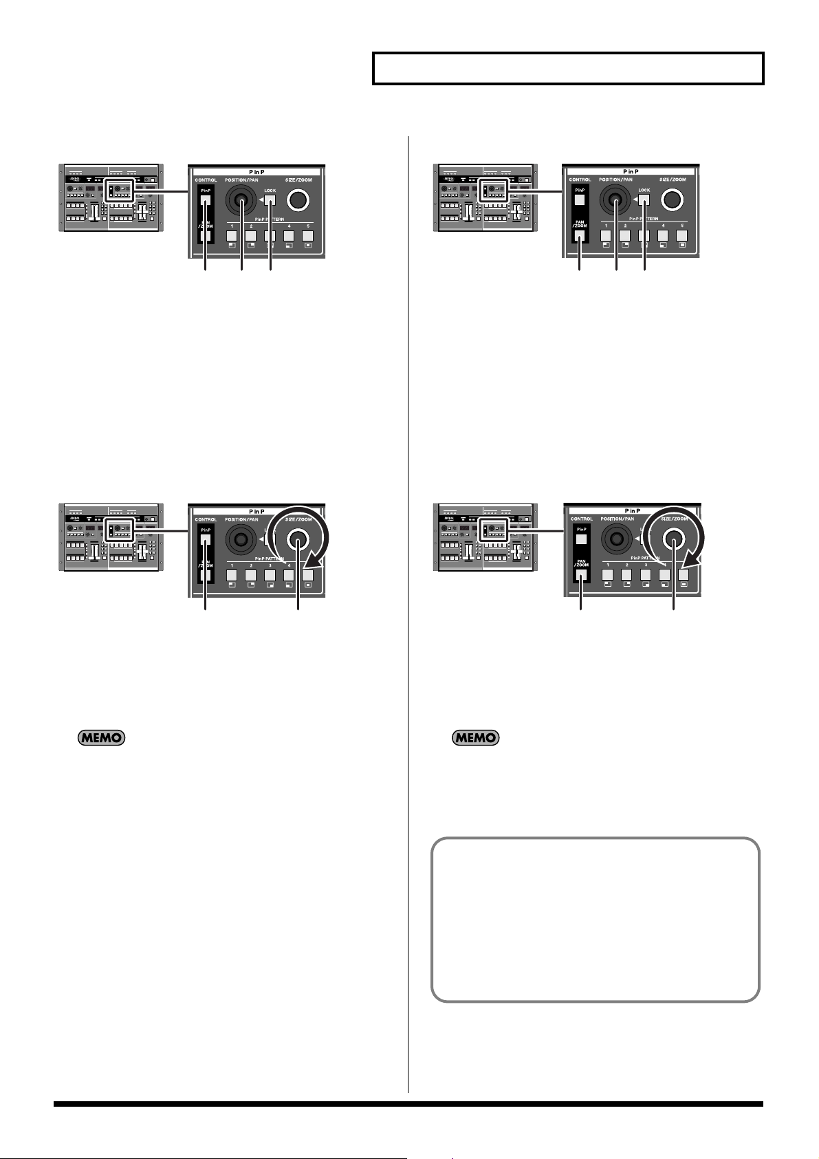
HD/RGB Section Operations
Adjusting the Position of the Sub-Screen (HD/RGB)
1 23
1. Press the P in P button (HD/RGB).
The P in P button (HD/RGB) lights up.
2. Press the LOCK button (HD/RGB).
The LOCK button (HD/RGB) is turned off.
At this time, operation of the POSITION/PAN joystick (HD/RGB) is
enabled.
3. Move the POSITION/PAN joystick (HD/RGB).
Adjust the placement of the sub-screen while viewing the screen.
Adjusting the Size of the Sub-Screen (HD/RGB)
Adjusting the Panning for the Sub-Screen (HD/RGB)
1. Press the PAN/ZOOM button (HD/RGB).
The PAN/ZOOM button (HD/RGB) lights up.
2. Press the LOCK button (HD/RGB).
The LOCK button (HD/RGB) is turned off.
At this time, operation of the POSITION/PAN joystick (HD/RGB) is
enabled.
3. Move the POSITION/PAN joystick (HD/RGB).
Adjust the panning in the sub-screen while viewing the screen.
Adjusting the Zoom in the Sub-Screen (HD/RGB)
1 23
1 2
1. Press the P in P button (HD/RGB).
The P in P button (HD/RGB) lights up.
2. Rotate the SIZE/ZOOM knob (HD/RGB).
Adjust the size of the sub-screen while viewing the screen.
P in P Settings Cleared When Power Is Turned Off
Be sure to save the P in P effect position, size, panning, and
zoom settings using the procedure described in Saving the P in
P Effect Settings (HD/RGB) (p. 32). Turning off the V-440HD's
power without saving the P in P settings will result in a loss of
the settings.
1 2
1. Press the PAN/ZOOM button (HD/RGB).
The PAN/ZOOM (HD/RGB) lights up.
2. Rotate the SIZE/ZOOM knob (HD/RGB).
Adjust the zoom for the sub-screen while viewing the screen.
Restoring the Original Subscreen Pan
To return the pan in the subscreen to its original settings after
changing the pan with the procedure above, hold down the
PAN/ZOOM button for at least five seconds.
P in P Position, Size, Pan, and Zoom Settings
The settings processed with the above procedure are stored to
the lit P in P PATTERN button and saved until the V-440HD is
turned off. Use of the settings that have been changed with the
procedure above after the power is turned off requires that the
settings be saved to the V-440HD.
For more detailed information, refer to Saving the P in P
Effect Settings (HD/RGB) (p. 32).
31
Page 32

HD/RGB Section Operations
A black part on screen B that is cut out.
And screen B composite screen A.
Screen A Screen B
2, 431
Saving the P in P Effect Settings (HD/RGB)
HD/RGB Section Key Composite Effects
You can use key composite effects in combining C-BUS and D-BUS
video. The portions with the key color in the video on the bus to
which the key composite effect is applied are made transparent, and
the video on the other bus is inserted as shown below.
The range of color used as the key is set with the “KEY LEVEL.”
To use P in P effect settings the next time the V-440HD is turned on,
save the settings to the P in P PATTERN buttons (HD/RGB).
When a P in P PATTERN button (HD/RGB) is held down for at least
five seconds, the P in P settings are saved to that button. All of the P
in P PATTERN buttons (HD/RGB) flash when saving of the settings
is completed.
Any settings previously stored to a P in P PATTERN button (HD/
RGB) are overwritten when new settings are saved to that button.
* To call up saved settings, press the P in P PATTERN button (HD/
RGB) to which the settings are saved.
Procedure for Using the HD/RGB Key Composite Effect
Advanced P in P Effect Settings (HD/RGB)
Make the P in P effect settings from the menu with the "3. HD/RGB
P in P/Zoom" parameters. Select the P in P PATTERN button (HD/
RGB) to which the settings are assigned with "P in P 1" to "P in P 5."
Settings can be made for the following parameters.
3. HD/RGB P in P/Zoom Settings Parameters
Size Subscreen size adjustment
X Position Subscreen horizontal position adjustment
Y Position Subscreen vertical position adjustment
Zoom Subscreen zoom size adjustment
Pan X Position Subscreen panning horizontal position adjustment
Pan Y Position Subscreen panning vertical position adjustment
Border Size
Border Color
Border Edge
* For more on the menus, refer to Menu Operations (p. 25).
* You can quickly access the menu’s P in P parameters by holding down
the MENU button and pressing a P in P PATTERN button (HD/
RGB).
* When key composite effect (p. 32) or multi-screen output (p. 39) are in
use, you can not use “Border Size“, “Border Color“ and “Border
Edge“ Function .
Subscreen border width adjustment
Subscreen border color adjustment
Subscreen edge
1. Select the key composite video with the C-BUS channel
buttons (HD/RGB) (or D-BUS channel buttons (HD/RGB)).
The portions of the selected video selected with the key effect are cut out.
2. Tilt the video fader (HD/RGB) to the opposite side from that
of the bus selected in Step 1.
3. Press the KEY ON Button (HD/RGB).
The button or buttons pressed in Step 1 flash. At this point, a button
flashing indicates that the key effect is being applied to the video
assigned to that button.
* When using the key composite effects while the P in P effect is in use,
the key effect settings are applied to the video with the P in P effect
applied.
* Use of the C-BUS channel buttons (HD/RGB) (or D-BUS channel
buttons (HD/RGB)) while combining video with the key composite
effects may result in disruption of the video image.
32
4. Tilt the video fader (HD/RGB) to the opposite direction.
The key composite effect is applied to the video selected in Step 1,
and this is combined with the video on the other bus.
* When key composite effect in use, you can not use switching effect’s
soft edge.
Page 33

Adjusting the Key Level
Adjust the key level by rotating the LEVEL knob (HD/RGB).
The key level is indicated in the LEVEL display (HD/RGB).
The key level can be set to any value from 0 to 255.
Advanced Key Composite Settings (HD/RGB)
You can set the following Key Composite parameters under "4. HD/
RGB Key" in the menu.
4. HD/RGB Key Settings Parameters
HD/RGB Key Type Key type
HD/RGB Key Level Key level
HD/RGB Key Soft Edge Key soft edge level
HD/RGB Section Operations
* For more on the menus, refer to Menu Operations (p. 25).
* You can quickly access the menu’s HD/RGB key composite parameters
by holding down the MENU button and pressing the HD/RGB KEY
ON Button.
33
Page 34

SD Section Operations
You can switch and compose SD video in the SD section.
Switching in the SD Section
You can switch the SD video input using the V-440HD’s video fader
(SD) along with the C-BUS channel buttons (SD) and B-BUS channel
buttons (SD).
A-BUS Channel Button
(SD)
B-BUS Channel Button
(SD)
Video Fader
(SD)
Switching Buses with the AUTO Button (SD)
The A-BUS and B-BUS switch automatically when the AUTO Button
(SD) is pressed. The time used for switching between the A-BUS and
C-BUS is set by rotating the TIME knob (SD). The time set with the
TIME knob (SD) is indicated in the TRANSITION TIME display
(SD). The time can be set to any value from 0 to 120 frames.
Selecting the Effect Applied When Switching Buses (SD)
The effect applied when switching the video is selected by pressing
the TRANSITION buttons (SD).
Switching Buses with the Video Fader (SD)
TIME Knob (SD)
AUTO Button (SD)
When the video fader (SD) is tilted towards the A-BUS, the video on
the A-BUS is output. Similarly, when the video fader (SD) is tilted
towards the B-BUS, the video on the B-BUS is output.
* For instructions on selecting the video on the A-BUS and B-BUS,
refer to Selecting the Bus Input (p. 35).
To confirm (preview) the video in the bus opposite that to
which the video fader (SD) is tilted, connect a television monitor
to the "SD PREVIEW OUT connector" (p. 19).
* In addition to the preview video, you can also output from the SD
PREVIEW OUT connector the same video that is output from SD
PGM OUT. Set this from the menu by selecting "13. SD Preview Out
Select" under "13. System."
Button Function Description
CUT Cut The video switches
when the video
fader (SD) reaches
the halfway point.
MIX
WIPE PATTERN 1-6 Wipe switching The video switches
Dissolve The video is mixed
as it gradually
switches according
to the angle of the
video fader (SD).
with a wipe effect,
with the wipe corresponding to the
angle of the video
fader (SD).
* This cannot be selected while the P in P effect (p. 35) is in use. If
the P in P effect is in
use when WIPE PATTERN 1-6 is selected,
MIX is selected automatically.
34
Page 35

Selecting the Bus Input
The video used on the A-BUS is selected by pressing the A-BUS
channel buttons (SD) 1-4. In the same manner, the video used on the
B-BUS is selected by pressing the B-BUS channel buttons (SD) 1-4.
SD Section Operations
SD Section P in P Effects
P in P (Picture in Picture) effects are applied to the video on the A-
BUS or B-BUS. The P in P effect is used just by pressing the P in P
PATTERN buttons (SD).
Background
Insert
When switching channels with the A-BUS channel buttons (SD)
and B-BUS channel buttons (SD), several frames is required to
switch the video in each bus. This is due to the time required to
lock the video signals when switching the video input formats
used in each channel. To shorten the duration, select the
following parameter from the menu and adjust the parameter.
* When you need to switch between Buses quickly, use the,
use Video Fader (SD) (p. 34)
* With some settings, noise may occur when the video is
switched. Set a value that provides sufficient time for
switching to avoid this problem.
• "13. System" - [10. SD Seamless Delay Time]
Keep the time setting somewhat short. The unit of time is
the field.
Customizing the Wipe
The wipe switching effects assigned to the TRANSITION (SD)
WIPE PATTERN 1-6 buttons can be set from the menu. You can
make settings for the wipe pattern, direction, and soft edge, and
combine these settings in various ways to create customized
wipe transitions.
* For more on the menus, refer to Menu Operations (p. 25).
* For more information about the different kinds of wipe patterns,
refer to "Customizing Wipe Transitions"(p. 29)
Procedure for Setting the SD Section P in P Effect
2, 41 3
1. Select the video to include in the sub-screen with the A-
BUS channel buttons (SD) (or B-BUS channel buttons (SD)).
2. Tilt the video fader (SD) to the opposite side from that of the
bus selected in Step 1.
3. Press a P in P PATTERN button (SD).
The button or buttons pressed in Step 1 flash. At this point, a button
flashing indicates that the P in P effect is being applied to the video
assigned to that button.
Button Sub-Screen Position (Factory Setting)
1
2
3
4
5
Upper left
Upper right
Lower right
Lower left
Center
4. Tilt the video fader (SD) to the opposite direction.
The video assigned to the channels corresponding to the flashing
buttons in Step 3 appears as the sub-screen.
* When using the P in P effect while a key composite effect is in use, the
P in P is applied to the video with the key effect settings included.
* Use of the A-BUS channel buttons (SD) (or B-BUS channel buttons
(SD)) while combining video with the P in P effect may result in
disruption of the video image.
* Wipe Patterns 1-6 cannot be selected with the "TRANSITION
buttons (SD)" (p. 34) while the P in P effect is in use.
35
Page 36

SD Section Operations
Adjusting the Position of the Sub-Screen (SD)
2 1
1. Press the LOCK button (SD).
The LOCK button (SD) is turned off. The LOCK button (SD) begins
to flash. At this time, operation of the POSITION joystick (SD) is
enabled.
2. Move the POSITION joystick (SD).
Adjust the placement of the sub-screen while viewing the screen.
Adjusting the Size of the Sub-Screen (SD)
Saving the P in P Effect Settings
To use P in P effect settings the next time the V-440HD is turned on,
save the settings to the P in P PATTERN buttons (SD).
When a P in P PATTERN button (SD) is held down for at least five
seconds, the P in P settings are saved to that button. All of the P in P
PATTERN buttons (SD) flash when saving of the settings is
completed.
Any settings previously stored to a P in P PATTERN button (SD) are
overwritten when new settings are saved to that button.
* To call up saved settings, press the P in P PATTERN button to which
the settings are saved.
Advanced P in P Effect Settings (SD)
Make the P in P effect settings from the menu with the "8. SD P in P"
parameters. Select the P in P PATTERN button (SD) to which the
settings are assigned with "P in P 1" to "P in P 5." Settings can be
1
made for the following parameters.
1. Rotate the SIZE knob (SD).
Adjust the size of the sub-screen while viewing the screen.
P in P Settings Cleared When Power is Turned Off
Be sure to save the P in P effect position, size, panning, and
zoom settings using the procedure described in "Saving the P in
P Effect Settings (SD)" at the right side of this page. Turning off
the V-440HD's power without saving the P in P settings will
result in a loss of the settings.
8. SD P in P Settings Parameters
PinP Size P in P size
PinP X Position Horizontal position
PinP Y Position Vertical position
PinP Border Size Border width
PinP Border Color Border color
PinP Trimming Width of portion trimmed from P in P edge
* For more on the menus, refer to Menu Operations (p. 25).
* You can quickly access the menu’s P in P parameters by holding down
P in P Position, Size, Pan, and Zoom Settings
The settings processed with the above procedure are stored to
the lit P in P PATTERN button and saved until the V-440HD is
turned off. Use of the settings that have been changed with the
procedure above after the power is turned off requires that the
settings be saved to the V-440HD.
For more detailed information, refer to "Saving the P in P Effect
Settings (SD)" at the right side of this page.
the MENU button and pressing a P in P PATTERN button (SD).
36
Page 37

SD Section Key Composite Effects
You can use key composite effects in combining A-BUS and B-BUS
video. The portions with the key color in the video on the bus to
which the key composite effect is applied are made transparent, and
the video on the other bus is inserted as shown below.
The range of color used as the key is set with the “KEY LEVEL.”
Screen A Screen B
SD Section Operations
Adjusting the Key Level
Adjust the key level by rotating the LEVEL knob (SD).
The key level is indicated in the LEVEL display (SD).
The key level can be set to any value from 0 to 255.
Advanced Key Composite Settings
A black part on screen B that is cut out.
And screen B composite screen A.
Procedure for Using the SD Key Composite Effect
2, 431
1. Select the key composite video with the A-BUS channel
buttons (SD) (or B-BUS channel buttons (SD)).
The portions of the selected video selected with the key effect are cut
out.
2. Tilt the video fader (SD) to the opposite side from that of the
bus selected in Step 1.
You can set the following Key Composite parameters under "9. SD
Key" in the menu.
9. SD Key Settings Parameters
SD Key Type Key type
SD Key Level Key level
SD Key Soft Edge Soft edge level
* For more on the menus, refer to Menu Operations (p. 25).
* You can quickly access the menu’s key composite parameters (SD) by
holding down the MENU button and pressing the KEY ON Button
(SD).
3. Press the KEY ON Button (SD).
The button or buttons pressed in Step 1 flash. At this point, a button
flashing indicates that the key effect is being applied to the video
assigned to that button.
* When using the key composite effects while the P in P effect is in use,
the key effect settings are applied to the video with the P in P effect
included.
* Use of the A-BUS channel buttons (SD) (or B-BUS channel buttons
(SD)) while combining video with the key composite effects may result
in disruption of the video image.
4. Tilt the video fader (SD) to the opposite direction.
The key composite effect is applied to the video selected in Step 1,
and this is combined with the video on the other bus.
37
Page 38

Other Operations
5 sec.
Using the PANEL PRESET Buttons
You can save configurations of panel controller settings to the
PANEL PRESET buttons. Saving complex settings to the PANEL
PRESET buttons enables you to call up these settings without any
complicated operations just by pressing the PANEL PRESET
buttons.
A different configuration of settings can be saved to each of the
PANEL PRESET buttons 1-15.
Configurations of panel controller settings Factory Preset
SD Section HD/RGB Section Others
P in P PATTERN Buttons (SD)
P in P LOCK Button (SD)
LEVEL Knob (SD)
KEY ON Button (SD)
Key Type (SD)
Key Soft Edge (SD)
A-BUS Channel Button (SD)
B-BUS Channel Button (SD)
TIME Knob (SD)
Video Fader (SD)
TRANSITION Button (SD)
P in P PATTERN Buttons (HD/RGB)
P in P LOCK Button (HD/RGB)
LEVEL Knob (HD/RGB)
KEY ON Button (HD/RGB)
Key Type (HD/RGB)
Key Soft Edge (HD/RGB)
C-BUS Channel Button (HD/RGB)
D-BUS Channel Button (HD/RGB)
TIME Knob (HD/RGB)
Video Fader (HD/RGB)
TRANSITION Button (HD/RGB)
OUTPUT FADE MODE
OUTPUT FADE LEVEL
Multi Screen On/Off Off p. 40
Multi Screen Type 1 x 1 p. 40
Off p. 35
ON p. 36
128 p. 37
Off p. 37
Luminance Key2
03 p. 52
1 ch p. 35
2 ch p. 35
1.0 p. 34
A-BUS p. 34
MIX p. 34
Off p. 30
ON p. 31
128 p. 33
Off p. 32
Luminance Key2
03 p. 50
1 ch p. 29
2 ch p. 29
1.0 p. 28
C-BUS p. 28
MIX p. 28
Auto p. 48
128 p. 50
Saving PANEL PRESET Settings
Related
Page
p. 52
p. 50
Calling Up PANEL PRESET Settings
Press a PANEL PRESET button 1-8.
The pressed button lights up, and the stored settings are called up
and reflected in the controllers.
Settings in PANEL PRESET 9-15 can be accessed by pressing the
SHIFT button so it’s lit, then pressing PANEL PRESET buttons 1-7.
* Pressing PANEL PRESET button 8 while the SHIFT button is lit
calls up the “Factory Preset” status (see table).
* Use of certain functions together may result in disruption of the video
images. We recommend testing settings configurations beforehand
when switching PANEL PRESET settings.
Copying Presets
Use the following procedure to copy settings from one PANEL
PRESET to another PANEL PRESET button.
1. Press the MENU button.
The menu is displayed.
2. Select "11. Panel Preset Edit."
3. Select "1. Copy."
4. Select the preset to be copied.
The preset shown at the left of the screen becomes the copy source.
5. Press the ENTER button.
6. Select the preset copy destination.
7. Press the ENTER button.
The message "Are You Sure?" appears.
8. Select "Yes."
9. Press the ENTER button.
The preset shown at the left of the screen is copied to the PANEL
PRESET button selected in Step 6.
To save PANEL PRESET settings, hold down the desired PANEL
PRESET button for at least five seconds. Once the PANEL PRESET is
saved, all of the PANEL PRESET buttons 1-8 flash.
* The content of the V-440HD’s internal memory cannot be written to
any external device.
38
Note that any settings in the copy-destination PANEL PRESET
are overwritten when this operation is executed.
Page 39

Other Operations
Exchanging Presets
Use the following procedure to exchange settings stored in one
PANEL PRESET with settings stored at another PANEL PRESET
button.
1. Press the MENU button.
The menu is displayed.
2. Select "11. Panel Preset Edit."
3. Select "2. Exchange."
4. Select the preset to be exchanged.
The preset shown at the left of the screen becomes the exchange
source.
5. Press the ENTER button.
6. Select the preset exchange destination.
7. Press the ENTER button.
The message "Are You Sure?" appears.
8. Select "Yes."
9. Press the ENTER button.
The preset shown at the left of the screen is exchanged with the
preset stored to the PANEL PRESET button selected in Step 6.
Multi-Screen Output
With MIDI used to link multiple V-440HDs, you can then use the
“multiscreen output,” whereby the video is partitioned and output
to multiple screens. With “multiscreen output,” one V-440HD is
used for control, with the operation of other V-440HDs synchronized
to it.
[Connecting Diagram]
Output Output Output
Video
MIDI
Master
* The V-440HD used as the control device is referred to here as the
“master.” The other V-440HDs whose operations are synchronized to
the master are referred to as “slaves.”
Slave1 Slave2
Connection Instructions for Multi-Screen Output
When using multiscreen output, use the following method to
connect the V-440HD with other devices.
* When making any connections, always be sure to turn off the power to
all devices before connecting them.
Video
MIDI
Connecting When Two Screens Are Used
When using multiscreen output with two screens, connect the master
and the slave directly to each other.
[Connecting Diagram]
[HD/RGB] [SD]
MIDI
Master
Loop Through
Slave
1. Distribute the video.
When using multiscreen output with two screens, use loop thru to
distribute the video from the HD/RGB input to the two V-440HDs
(p. 21).
* When using loop thru, set the HD/RGB 75
to OFF.
Component - D-sub
Composite - Video
Ω
TERMINATOR switch
39
Page 40

Other Operations
12
12
34
2. Connect via MIDI.
Using a MIDI cable, connect the master V-440HD’s MIDI OUT/
THRU connector to the MIDI IN connector on the slave V-440HD.
3. Connect the screens.
Connect the left screen to the master V-440HD’s HD OUT or RGB
connectors.
Connect the right screen to the slaved V-440HD’s HD OUT or RGB
connectors.
Making the Multi-Screen Settings
After connecting the devices according to the procedures described
on p. 39 and p. 40, make the V-440HD settings. Set all of the V-
440HDs as described below.
1. Press the MENU button.
2. Select "12. Multi Screen."
Connecting When Three or More
Screens Are Used
Using multiscreen output with three or more screens requires use of
to distribute the video and MIDI signals for the master and multiple
connected slaves.
* Satisfactory image quality may not be obtainable using loop thru to
distribute the video to three or more V-440HD.
[Connecting Diagram]
HD
Distributer
Master
Slave1
Slave2
1. Distribute the video.
When using multiscreen output with three or more screens, use to
distribute the video to each input.
* Use an interface compatible with the format of the video being
distributed.
* Make sure that the same type of video signals are input to each V-
440HD. If, for example, you are grouping S-Video signals in SD IN
Channel 4, make sure that the signal formats are the same, even
though the video may have the same field of view.
2. Connect via MIDI.
Use a MIDI cable to connect the MIDI OUT/THRU connector on the
master V-440HD to the MIDI IN connector on the slave V-440HD.
Connect any additional V-440HDs in the same manner.
* If connecting multiple V-440HDs results in attenuation of the
operational signals, use a MIDI interface (e.g., Edirol UM-880) to
multiplex the MIDI output signals from the master V-440HD.
3. Connect the screens.
Send the video output from the master and slaves as shown in the
table. Connect the master and slave HD OUT or RGB outputs to the
corresponding video output devices.
MIDI MIDI
RGB
Distributer
Distributer
[HD]
[RGB]
SD
[SD]
3. Set "2. Multi Screen Mode."
Select the screen layout. The master and slave values are set
automatically.
* For more on the screen position, refer to "Slave Numbers and Screen
Positions."
4. 4. Set "3. Multi Screen ID."
This sets the screen positions for the master and slave V-440HDs.
Referring to "Slave Numbers and Screen Positions" below, make
selections from Screen1-Master to Screen6-Slave. Assign Screen1-
Master to the V-440HD corresponding to the highest priority MIDI
signal (the uppermost unit in the right figure on p. 40). V-440HDs set
to Screen2-Slave to Screen6-Slave become slave devices.
* For more on the MIDI setting, refer to Controlling the V-440HD
from an External Device Via MIDI and Linking Operations
Via MIDI (p. 45).
Turning the Multi Screen Function On
1. Select "On" for the master V-440HD's "1. Multi Screen On/Off" setting.
After making the settings in Steps 1-4 of "Making the Multi Screen
Function Settings" for all of the V-440HDs, select "On" in "1. Multi
Screen On/Off" under "12. Multi Screen" in the menu for the master
V-440HD. The Multi Screen function is switched on, and each V-
440HD displays the video corresponding to its assigned screen
position.
Turning the Multi Screen Function Off
Select "Of" in "1. Multi Screen On/Off" under "12. Multi Screen" in
the menu for the master V-440HD.
Position of screen Position of screen
2x1 3x1
123
2x2 3x2
123
456
* Numbers in the figure indicate slave order.
40
Page 41

Other Operations
Advanced Multi-Screen Settings
When using the Multi Screen function, the settings may need to be
changed if, for example, screens overlap due to the screen sizes and
positions.
Make advanced settings for the Multi Screen function from the menu
with "12. Multi Screen" (p. 53). The following parameters are
enabled.
12. Multi Parameter Settings Parameters
Multi Screen On / Off Switches the Multi Screen function on and off
Multi Screen Type Number of screens used with Multi Screen
Multi Screen ID V-440HD rank and screen position
Screen1 X Size Screen1 (master) screen horizontal size
Screen1 Y Size Screen1 (master) screen vertical size
Screen1 X Position Screen1 (master) screen horizontal position
Screen1 Y Position Screen1 (master) screen vertical position
Screen2 X Size Screen2 screen horizontal size
Screen2 Y Size Screen2 screen vertical size
Screen2 X Position Screen2 screen horizontal position
Screen2 Y Position Screen2 screen vertical position
Screen3 X Size Screen3 screen horizontal size
Screen3 Y Size Screen3 screen vertical size
Screen3 X Position Screen3 screen horizontal position
Screen3 Y Position Screen3 screen vertical position
Screen4 X Size Screen4 screen horizontal size
Screen4 Y Size Screen4 screen vertical size
Screen4 X Position Screen4 screen horizontal position
Screen4 Y Position Screen4 screen vertical position
Screen5 X Size Screen5 screen horizontal size
Screen5 Y Size Screen5 screen vertical size
Screen5 X Position Screen5 screen horizontal position
Screen5 Y Position Screen5 screen vertical position
Screen6 X Size Screen6 screen horizontal size
Screen6 Y Size Screen6 screen vertical size
Screen6 X Position Screen6 screen horizontal position
Screen6 Y Position Screen6 screen vertical position
Temporarily Switching Off the Multi-Screen Function for the Master and Slave Devices
To temporarily switch off the Multi Screen function for the master
and slave devices, press the MIDI button so that the button's light
goes off. Multi Screen is not operational while the MIDI button light
is off.
Differences in Screen Colors
When using the Multi Screen function, discrepancies in color
may be visible in the receiving the final output from each V-
440HD. If this occurs, use the following procedure to adjust the
final output from each V-440HD.
1. Select ”1. HD/RGB Output” (p. 48) from the menu for the
master V-440HD, then adjust the color.
2. Select”2. HD/RGB Input” (p. 49) or ”7. SD Input” (p. 51)
from the menu for the master V-440HD, then adjust the
color in each of the video inputs.
3. Set all of the slave V-440HDs to the values set in Step 2.
4. Select”1. HD/RGB Output” (p. 48) from the menu for the
slave V-440HDs, then match the color to that in the master
video.
About Manual Settings for the
Master and Slave V-440HDs
You can set the screen size and position of the master and slave V-
440HDs manually with the parameters "4. Screen1 X Size" to "27.
Screen6 Y Position."
* The values that can be set manually depend on the size of the final
video output.
* After making manual settings, the values for "4. Screen1 X Size" to
"27. Screen6 Y Position" are changed automatically when the value in
"2. Multi Screen Type" is changed.
* After making manual settings, changing the value in 1. HD/RGB
Output (p. 48) may, depending on the settings, result in nothing
displayed by the slave devices. If this occurs, set the "2. Multi Screen
Type" value again, then redo the manual settings.
41
Page 42

Other Operations
Switching Between NTSC and PAL Displaying Test Patterns
You can switch the V-440HD between NTSC and PAL formats.
Switching Between NTSC and PAL
from the Menu
1. Press the MENU button.
The menu is displayed.
2. Select "13. System."
3. Select "1. System Frame Rate."
4. Select NTSC or PAL.
If using NTSC, select "60-NTSC"; select "50-PAL" if using PAL.
The V-440HD can output color bars. This is useful when making
output settings.
* For more on the menus, refer to Menu Operations (p. 25).
Switching to NTSC or PAL When the
Power is Turned On
NTSC and PAL are switched when the V-440HD’s power is turned
on while HD/RGB button 1 and 4 are held down.
The V-440HD outputs color bar test patterns. Use of this patterns is
convenient when making the output settings.
Outputting the Test Pattern from
the HD/RGB OUT Connectors
1. Press the MENU button.
The menu is displayed.
2. Select "1. HD/RGB Output."
3. Select "14. Test Pattern Select."
Select the pattern to be displayed from the menu.
Value Displayed
Off (No output)
Color Bar 75%
Color Bar 100%
* For more on the menus, refer to Menu Operations (p. 25).
Outputting the Test Pattern from
the SD OUT Connectors
1. Press the MENU button.
The menu is displayed.
2. Select "6. SD Output."
3. Select "6. Color Bar."
Select On from the menu and press the ENTER button.
* For more on the menus, refer to Menu Operations (p. 25).
42
Page 43

Reference
About the HD/RGB IN Connectors (D-Sub)
The V-440HD's HD/RGB IN (D-Sub) connectors accept either analog
component signals or RGB signals. In addition, the Loop Thru
function can be used for thru output of analog component signals or
RGB signals input via the HD/RGB IN connectors (BNC).
These input signals are output with the following specifications.
Inputting and Outputting Analog
Component Signals
Connector Type: D-SUB 15-pin shrink terminal
Pin number Signal name Pin Connections
1 Pr
2 Y
3 Pb
4 GND
5 GND
6 Pr-GND
7 Y-GND
8 Pb-GND
9 N.C.
10 SYNC-GND
11 (Reserved)
12 -
13 -
14 -
15 -
FG Frame GND
Inputting and Outputting RGB
Signals
Connector Type: D-SUB 15-pin shrink terminal
Pin number Signal name Pin Connections
1 Red / Pr
2 Green / Y
3 Blue / Pb
4 GND
5 GND
6 R-GND / Pr-GND
7 G-GND / Y-GND
8 B-GND / Pb-GND
9 N.C.
10 SYNC-GND
11 (Reserved)
12 (VESA DDC RESERVED)
13 H-SYNC (*)
14 V-SYNC (*)
15 (VESA DDC RESERVED)
FG Frame GND
51
10 6
15 11
51
10 6
15 11
About the RGB OUT Connectors (D-Sub)
The V-440HD's RGB OUT connectors output RGB signals.
* Analog Component signal is not output from RGB OUT Connector.
Outputting RGB Signals
Connector Type: D-SUB 15-pin shrink terminal
Pin number Signal name Pin Connections
1 Red
2 Green
3 Blue
4 GND
5 GND
6 R-GND
7 G-GND
8 B-GND
9 N.C.
10 SYNC-GND
11 (Reserved)
12 (VESA DDC RESERVED)
13 H-SYNC
14 V-SYNC
15 (VESA DDC RESERVED)
FG Frame GND
About Loop Thru
The HD/RGB IN connector (D-sub) and HD/RGB IN connector
(BNC) for any particular channel are linked internally within
the V-440HD. So, for example, if analog component signals are
input to the Channel 1 HD/RGB IN connector (D-sub), the same
signals are output from the Channel 1 HD/RGB IN connector
(BNC). This function is called "Loop Thru."
Using Loop Thru, you can monitor the video output of each
video input on a television monitor, or even use the connections
for multiscreen output.
However, the following precautions must be observed.
• Set the TERMINATOR 75Ω switch to ON when Loop
Thru is not being used
Some devices may not function properly when Loop Thru
is not in use unless the TERMINATOR 75Ω switch is set to
ON.
• Using more than one pass with Loop Thru may result
in attenuation of the video
With three or more V-440HDs connected using Loop Thru,
the video signal becomes more attenuated the further
down the signal path the V-440HD is. When using identical
video with three or more V-440HDs, be sure to use a
commercially available video multiplexer.
51
10 6
15 11
43
Page 44

Reference
About the TALLY Connectors
When connecting a television monitor equipped with a TALLY input to the
V-440HD, you can have the television monitor’s TALLY lamp light up. The
TALLY lamp lights up according to the switching status, allowing you to
confirm the channel being used on the monitor. The switching status of the
SD video is output from the TALLY 1 connector, and the switching status
of the HD/RGB video is output from the TALLY 1 (HD/RGB) connector.
* Obtain a separate cable for use in connecting the V-440HD with the
TALLY input-equipped television monitor.
About TALLY Types
The V-440HD is capable of outputting three different types of tally
signal, Type 1-Type 3. When Type 1-3 is selected, you can then select
the terminal from which the tally signals are output (refer to "TALLY
Terminal Specifications" below).
You can select the tally signal output type in "12. Tally Signal" under
"13. System" in the menu; select the output type suited to the
particular conditions.
* For more on the menus, refer to Menu Operations (p. 25).
TALLY Connector Specifications
Connector Type: D-SUB 15-pin shrink terminal
• TALLY 1 (SD) Connector Pin Assignments
Pin number Signal name Pin Connections
1 SD 1ch Type 1
2 SD 1ch Type 2
3 SD 1ch Type 3
4 GND
5 SD 4ch Type 1
6 SD 2ch Type 1
7 SD 2ch Type 2
8 SD 2ch Type 3
9 GND
10 SD 4ch Type 2
11 SD 3ch Type 1
12 SD 3ch Type 2
13 SD 3ch Type 3
14 GND
15 SD 4ch Type 3
• TALLY 2 (HD/RGB) Connector Pin Assignments
Pin number Signal name Pin Connections
1 HD/RGB 1ch Type 1
2 HD/RGB 1ch Type 2
3 HD/RGB 1ch Type 3
4 GND
5 HD/RGB 4ch Type 1
6 HD/RGB 2ch Type 1
7 HD/RGB 2ch Type 2
8 HD/RGB 2ch Type 3
9 GND
10 HD/RGB 4ch Type 2
11 HD/RGB 3ch Type 1
12 HD/RGB 3ch Type 2
13 HD/RGB 3ch Type 3
14 GND
15 HD/RGB 4ch Type 3
51
10 6
15 11
51
10 6
15 11
About the REMOTE Connector
You can use the REMOTE connector to enable switching, control of
effects, and other operations from a computer or other external
control device.
REMOTE Connector Specifications
• Transmission Format: Start-stop synchronization
(asynchronous), full duplex
• Transmission Rate: 9600 bps (Initial setting)/19200 bps
(This can be changed in the menu with "8. REMOTE Baudrate"
under “13. System” (p. 54).)
• Parity: None
• Data Length: 8 bits
• Stop Bit Length: 1 bit
• Encoding: ASCII
• Flow Control: XON/XOFF
Pin number Signal name Pin Connections
1 DCD
2 RXD
3 TXD
4 DTR
5 GND
6 DSR
7 RTS
8 CTS
9 RI
* The V-440HD’s connectors are male. To connect to a computer, use a
female-female crossover cable.
Cable Connections:
V-440HD Computer
1 : DCD
2 : RXD
3 : TXD
4 : DTR
5 : GND
6 : DSR
7 : RTS
8 : CTS
9 : RI
1 : DCD
2 : RXD
3 : TXD
4 : DTR
5 : GND
6 : DSR
7 : RTS
8 : CTS
9 : RI
Setup Procedure
Use the following procedure to set up the control device and V-
440HD.
1. Connect the V-440HD and control device with a REMOTE
cable.
2. Turn on the power to the control device.
3. Set the communications protocol for the control device.
4. Turn on the power to the V-440HD.
5. Begin operation.
* For more on commands, refer to REMOTE Command Reference
(p. 56).
51
96
44
Page 45

Controlling the V-440HD from an External Device Via MIDI
The V-440HD can be controlled from an external device using MIDI.
For example, you can use a Roland multitrack recorder to control
video performances that are synchronized to the sounds.
This section explains some basics of MIDI and describes the use of
MIDI messages with the V-440HD.
Reference
M
IDI Connectors
The following three types of connectors are used in exchanging MIDI
messages (data handled with MIDI). On the V-440HD, the MIDI
OUT and MIDI THRU are combined in one connector. The function
is switched according to the operation being performed.
MIDI IN: MIDI messages from other MIDI devices are received here.
MIDI OUT: MIDI messages from the V-440HD are transmitted from
here. MIDI THRU: MIDI messages received at the MIDI IN
connector are output as is.
What is MIDI?
MIDI, an abbreviation for Musical Instrument Digital Interface, is an
international standard created to enable exchange of performance
data among devices. Any MIDI-compatible device can be connected
simply with a MIDI cable, allowing transfer of performance data and
control of device operations and settings.
Linking Operations Via MIDI
You can use MIDI to link the operation of multiple V-440HDs. To do
so, make the following settings.
• Linking operation of multiple V-440HDs
Select "14. MIDI Setup" (p. 55) from the menu and set "4. MIDI
Out/Thru Switch" to "Thru."
• Linking operation using "Multi-Screen Output" (p. 39)
Controlling the V-440HD from an External Device Via MIDI
After switching on the power (when V-LINK is off), MIDI messages are
output from MIDI OUT in response to adjustments with the corresponding
buttons and knobs. In addition, adjustments identical to those made with the
buttons and knobs are made when the corresponding MIDI messages are
received at MIDI IN.
* For more about MIDI messages, refer to the "
59).
MIDI implementation
(p.
For instructions on linking operation of multiple V-440HDs with
the Multi-Screen function, refer to "Multi-Screen Output" (p. 39).
Temporarily Switching Off Linked Operation
You can stop reception of MIDI signals temporarily by pressing the
MIDI button. This stops linked operation via MIDI and enables
independent functioning of one individual V-440HD.
To restore linked operation through MIDI, press the MIDI button
once more so the button is lit.
[Things that receives MIDI message]
1
MIDI Button
3
PANEL PRESET Button
2
3
OUTPUT FORMAT Button
TIME Knob
6
POSITION Joystick (SD)
7
LOCK Button (SD)
8
SIZE Knob (SD)
9
P in P PATTERN Button (SD)
10
LEVEL Knob (SD)
11
KEY ON Button (SD)
6 7 8
9 10
13 1615
14 17
12
TIME Knob (SD)
13
A-BUS Channel Button (SD)
14
B-BUS Channel Button (SD)
15
Video Fader (SD)
16
TRANSITION Button (SD)
17
AUTO Button (SD)
1
11 12
2
1918
20 21
22 23
26 28 29
27 30
18
POSITION/SIZE Button (HD/RGB)
PAN/ZOOM Button (HD/RGB)
19
POSITION/PAN Joystick (HD/RGB)
20
LOCK Button (HD/RGB)
21
SIZE/ZOOM Knob (HD/RGB)
22
P in P PATTERN Button (HD/RGB)
23
LEVEL Knob (HD/RGB)
445
24 25
5
OUTPUT FADE Button
24
KEY ON Button (HD/RGB)
25
TIME Knob (HD/RGB)
26
C-BUS Channel Button (HD/RGB)
27
D-BUS Channel Button (HD/RGB)
28
Video Fader (HD/RGB)
29
TRANSITION Button (HD/RGB)
30
AUTO Button (HD/RGB)
45
Page 46

Reference
MIDI Messages Handled by the V440HD
The following MIDI messages are handled with the V-440HD.
• Bank Select and Program Change
These messages are used for switching tones. On the V-440HD, Bank
Select messages are used to select the bus, and Program Change
messages are used to select channels.
• Control Change Messages
These generally transmit information, such as vibrato, hold, and
volume, that enhances the realism of performances. All functions are
organized according to a controller number from 0 to 127, with each
function being assigned its own number. On the V-440HD, these
messages are used with the video faders and knobs.
@p
• System Exclusive Messages
These messages are used for transmitting device-specific settings.
On the V-440HD, these messages are used for transmitting P in P
settings and when setting the Multi Screen outputs.
When System Exclusive messages are exchanged, MIDI
transmissions are distinguished by Device IDs rather than MIDI
channels. When exchanging System Exclusive messages, set the
devices to the same Device ID.
MIDI channels
MIDI is able to send information over a single MIDI cable
independently to two or more MIDI devices. This is made possible
by the concept of MIDI channels. You can think of MIDI channels as
being somewhat similar in function to the channels on a television.
By changing the channel of a TV set, you can view a variety of
programs being transmitted by different broadcast stations. This is
because data is received only from the transmitter whose channel is
selected on the receiver.
In the same way, a MIDI device whose receive channel is set to [1]
will receive only the data being transmitted by another MIDI device
whose transmit channel is also set to [1.]
MIDI Implementation Chart
The use of MIDI makes it possible to communicate with a broad
range of electronic musical instruments. However, this does not
mean that all MIDI messages can be exchanged among all devices.
Only those MIDI messages that both of the communicating devices
are designed to understand can be exchanged. The owner’s manual
that comes with a MIDI device includes a MIDI Implementation
Chart (p. 66). Such charts allow you to easily find out which MIDI
messages that device can transmit and receive. When using MIDI
devices, compare the charts for the devices that will be
communicating to check which MIDI messages are compatible.
Control Using V-LINK
You can have control of the V-440HD be linked to the performance
of a V-LINK compatible instrument (when V-LINK is on)
What is V-LINK?
V-LINK ( ) is the name of a feature that makes it possible to
use MIDI to control visual presentations that are designed to
accompany a musical performance. Thanks to V-LINK, it’s easy to
present a variety of video linked to the expressive elements of a
performance.
With V-LINK, you can use Roland and Edirol instruments and music
devices to control the video without any degradation in the
instruments’ original functions (producing sounds).
Instructions for Using V-LINK
For information on switching V-LINK on and off, refer to the
Owner’s Manual for the V-LINK compatible device to be connected
to the V-440HD.
* You can confirm the V-LINK MODE status by checking whether or
not the MIDI button is lit. Select "14. MIDI setup"(p. 55) from the
menu and set “MIDI Sw Mode” to “V-Link Indicator“.
* To see which functions can be controlled from an external device with
V-LINK, refer to the MIDI Implementation on p. 66 as well as the
MIDI Implementation for the device being connected. The functions
that can be controlled may vary according to the device being
connected and the settings.
Initial V-LINK Status Settings (V-440HD
Receives Only the V-LINK ON Message)
Rx Channel 1
Tx Channel 1
SD A Bus Ach:1
SD B Bus Bch:2
SD Auto Switch -
SD Transition Pattern Mix
SD Transition Time 0.0sec
SD Video Fader Ach100%
SD Key Switch OFF
SD PinP Switch OFF
SD PinP Lock Switch OFF
HD C Bus Cch:1
HD D Bus Dch:2
HD Auto Switch -
HD Transition Pattern Mix
HD Transition Time 0.0sec
HD Video Fader Cch100%
HD Key Switch OFF
HD PinP Switch OFF
HD PinP Lock Switch OFF
PinP/Zoom Switch PinP
Panel Preset Switch OFF
Output Format Switch 1
Output Fade Mode Auto
Fade Switch -
Fade Level MAX
46
Page 47
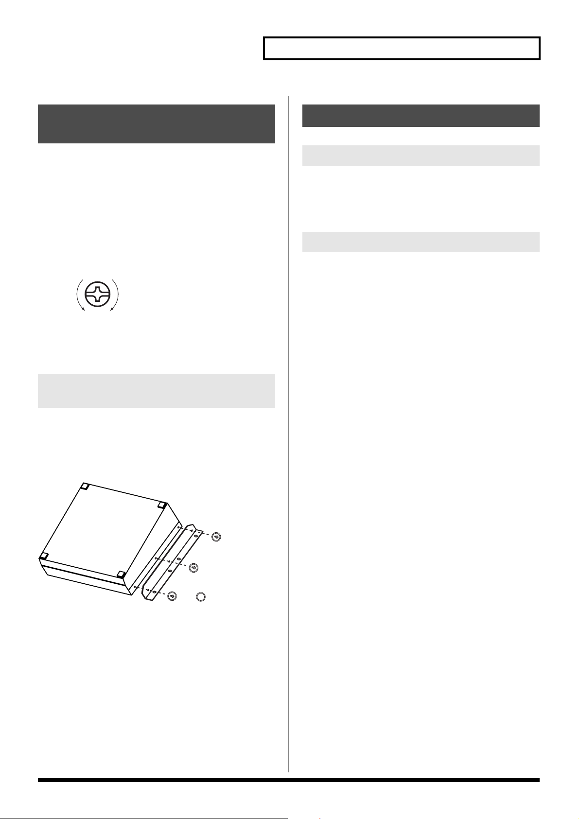
Reference
Installing the Rack Mount Hardware
Precautions to Observe When
Attaching the Rack Mount
Hardware
• Use the proper size Phillips head screwdriver for the screw
heads (No. 2 driver). Use of a screwdriver that does not fit the
screw heads may result in the heads becoming stripped.
• When removing the screws, turn the screwdriver in the
counterclockwise direction. To tighten the screws, turn the
screwdriver in the clockwise direction.
tightenloosen
• Remove only the specified screws when attaching the rack
mount hardware.
• Once the installation is complete, check it again to make sure
that is has been done correctly.
Instructions for Attaching the Rack Mount Hardware
About Maintenance
Daily Maintenance
Loss of air flow due to dust accumulating at the exhaust vent may
inhibit the forced cooling function. Using a vacuum cleaner or other
means, regularly remove accumulations of dust from the exhaust
vent and intake vent.
About the Fan
Malfunctioning of the fan will prevent the forced cooling function
from working properly, posing the danger of overheating and other
problems. If you cannot confirm that the fan is operational, please
consult your Roland dealer or a Roland ED Service Station.
1. Before attaching the rack mount hardware, turn the power
off to the V-440HD and all connected devices and
disconnect all power cords and connection cables.
2. Turn the V-440HD over and remove the screws specified in
the following figure to remove the rack mount hardware.
(V-440HD Bottom Panel)
Screws to be removed
3. Return the screws removed in Step 2 to their original holes
and secure.
47
Page 48

Menu Parameters
* For more on menus, see p. 24.
1. HD/RGB Output
Settings for the final output are made here.
Parameters Notes Values
1- 1. Output Format (1080i) Sw (1080i) video format Refer to “About the Final Output Format.”
1- 2. Output Format (720p) Sw (720p) video format Refer to “About the Final Output Format.”
1- 3. Output Format (RGB) Sw (RGB) video format Refer to “About the Final Output Format.”
1- 4. Output Format Sw Lock OUTPUT FORMAT button lock Off, On
1- 5. Zooming Final output scaling adjustment 80.0 ~ 120.0
1- 6. Bright Final output brightness adjustment -64 ~ +64
1- 7. Contrast Final output contrast adjustment -64 ~ +64
1- 8. Saturation Final output saturation adjustment -64 ~ +64
1- 9. Red Final output red adjustment -64 ~ +64
1- 10. Green Final output green adjustment -64 ~ +64
1- 11. Blue Final output blue adjustment -64 ~ +64
1- 12. Output Fade Mode Final output fade control adjustment Auto, Manual
1- 13. Output Fade Color Final output fade color setting Black, White
1- 14. Test Pattern Select Test pattern output Off, 75% Color Bar, 100% Color Bar
Refer to “About the Final Output Fade Control”
About the Final Output Format
You can select from the following formats for use with the final output.
Component RGB
1080i (50/60) 1280x1024/60
720p (50/60) 1280x768/75
480p (50/60) 1280x768/60
480i (50/60) 1024x768/75
1024x768/60
800x600/75
800x600/60
640x480/75
640x480/60
* Numbers in parentheses for the component formats indicate frame rate. Frame rates for parameters with (50/60) can be set with the value in “1.
System Frame Rate” under “13. System.”
* Units are [horizontal (pixels) x vertical (lines) / frame rate (Hertz)].
About the Final Output Fade Control
There are two final output fade modes (p. 23), which can be changed as needed.
[1-12. Output Fade Mode Settings and Function of Each Controller]
Auto Manual
OUTPUT FADE Button Fades in/out according to value set with TIME knob -(Flashes when video is fading out)
TIME Knob Sets Fade-in/Fade-out time for final output Controls fade-in/fade-out time
48
Page 49

2. HD/RGB Input
Settings for the input from the HD/RGB IN connectors are made here.
Parameters Notes Values
2- 1. HD/RGB Ch A/B Sets input for SD section video input to HD/RGB * Refer to “HD/RGB Input Parameters.”
2- 2. HD/RGB Ch 1 Sets video input to Channel 1 of the HD/RGB IN connectors * Refer to “HD/RGB Input Parameters.”
2- 3. HD/RGB Ch 2 Sets video input to Channel 2 of the HD/RGB IN connectors * Refer to “HD/RGB Input Parameters.”
2- 4. HD/RGB Ch 3 Sets video input to Channel 3 of the HD/RGB IN connectors * Refer to “HD/RGB Input Parameters.”
2- 4. HD/RGB Ch 4 Sets video input to Channel 4 of the HD/RGB IN connectors * Refer to “HD/RGB Input Parameters.”
HD/RGB Input Parameters
Parameters Notes Values
1. Format Auto Detect Function automatically distinguishes input *1 Auto, Manual
2. Input Format Input format select *1*2 * Refer to “About the HD/RGB Input Format”
3. Pre Scaling Mode Switches scaling adjustment function on and off Auto, Manual
4. Manual Pre Scaling Adjusts scaling ratio when full scaling used *3 90.0 ~ 110.0%, Auto
5. Scaling Type Scaling method
6. Manual X Scale Adjusts the horizontal expansion ratio *4 0010 ~ +1000
7. Manual Y Scale Adjusts the vertical expansion ratio *4 0010 ~ +1000
8. X Position Fine adjustment of the horizontal start position -64 ~ +64
9. Y Position Fine adjustment of the vertical start position -64 ~ +64
10. Brightness Brightness adjustment -64 ~ +64
11. Contrast Contrast adjustment -64 ~ +64
12. Saturation Saturation adjustment -64 ~ +64
13. Red Red adjustment -64 ~ +64
14. Green Green adjustment -64 ~ +64
15. Blue Blue adjustment -64 ~ +64
16. Frequency Fine adjustment of the Sampling Frequency *1 -64 ~ +64
17. Phase Fine adjustment of the Sampling Phase *1 -64 ~ +64
*1 Cannot be set in HD/RGB Channel A/B. Parameter numbers are in sequence, with these parameters omitted.
*2 Enabled when Format Auto Detect is set to Manual.
*3 Enabled when Pre Scaling Mode is set to Manual.
*4 Enabled when Scaling Type is set to Manual.
Menu Parameters
Full Scale. Fixed Aspect: Letter, Fixed Aspect:Crop, Manual
About the HD/RGB Input Format
The V-440HD inputs component and RGB video in the formats shown in the following table.
Component RGB
480/60p 640x480/60
576/50p 640x480/75
1080/60i 800x600/60
1080/50i 800x600/75
720/60p 1024x768/60
720/50p 1024x768/75
1280x768/60
1280x768/75
1280x1024/60
* RGB units are [horizontal (pixels) x vertical (lines) / frame rate (Hertz)].
49
Page 50

Menu Parameters
3. HD/RGB PinP/Zoom
Advanced settings for the HD/RGB section’s P in P effect are made here.
Parameters Notes Values
3- 1. HD/RGB PinP1 Sets P in P PATTERN button (HD/RGB) 1 * Refer to “HD/RGB P in P Parameters.”
3- 2. HD/RGB PinP2 Sets P in P PATTERN button (HD/RGB) 2 * Refer to “HD/RGB P in P Parameters.”
3- 3. HD/RGB PinP3 Sets P in P PATTERN button (HD/RGB) 3 * Refer to “HD/RGB P in P Parameters.”
3- 4. HD/RGB PinP4 Sets P in P PATTERN button (HD/RGB) 4 * Refer to “HD/RGB P in P Parameters.”
3- 5. HD/RGB PinP5 Sets P in P PATTERN button (HD/RGB) 5 * Refer to “HD/RGB P in P Parameters.”
HD/RGB P in P Parameters
Parameters Notes Values
1. Size Subscreen size adjustment 20 ~ 100%
2. X Position Subscreen horizontal position adjustment -44 ~ +44%
3. Y Position Subscreen vertical position adjustment -44 ~ +44%
4. Zoom Subscreen zoom size adjustment 100 ~ 1000%
5. Pan X Position Subscreen panning horizontal position adjustment -100.0 ~ +100.0%
6. Pan Y Position Subscreen panning vertical position adjustment -100.0 ~ +100.0%
7. Border Size Subscreen border width adjustment 0 ~ 15
8. Border Color Subscreen border color adjustment Black, Red, Green, Yellow, Blue, Magenta, Cyan,
9. Border Edge Subscreen edge Hard, Soft
* When key composite effect (p. 32) or multi-screen output (p. 39) are in use, you can not use “Border Size“, “Border Color“and “Border
Edge“Function.
* For more on the HD/RGB section’s P in P effects, see p. 30.
(Changes according to the subscreen position)
(Changes according to the subscreen position)
(Changes according to the subscreen position)
White
4. HD/RGB Key
Advanced settings for the HD/RGB section’s key composite effects are made here.
Parameters Notes Values
4- 1. HD/RGB Key Type Key type Luminance Key1 (White), Luminance Key2 (Black),
4- 2. HD/RGB Key Level Key level 0 ~ 255
4- 3. HD/RGB Key Soft Edge Key soft edge level 0 ~ 15
* For more on the HD/RGB section’s key composite effects, see p. 32.
Chroma Key1 (Blue), Chroma Key2(Green)
50
Page 51

5. HD/RGB Wipe Select
Settings for the TRANSITION buttons’ (HD/RGB) WIPE PATTERN 1-6 are made here.
Parameters Notes Values
5- 1. HD/RGB Wipe Sw 1
5- 2. HD/RGB Wipe Sw 2
5- 3. HD/RGB Wipe Sw 3
5- 4. HD/RGB Wipe Sw 4
5- 5. HD/RGB Wipe Sw 5
5- 6. HD/RGB Wipe Sw 6
TRANSITION Button (HD/RGB) Parameters
Parameters Notes Values
1. Wipe Pattern Wipe pattern setting Horizontal, Vertical, Horizontal Open, Vertical Open, Box, Cross *
2. Wipe Reverse Wipe direction Off, On
3. Wipe Edge Type Soft edge function Hard, Soft
* For more on wipe patterns, see p. 28.
Sets TRANSITION button (HD/RGB) WIPE PATTERN 1
Sets TRANSITION button (HD/RGB) WIPE PATTERN 2
Sets TRANSITION button (HD/RGB) WIPE PATTERN 3
Sets TRANSITION button (HD/RGB) WIPE PATTERN 4
Sets TRANSITION button (HD/RGB) WIPE PATTERN 5
Sets TRANSITION button (HD/RGB) WIPE PATTERN 6
Menu Parameters
* Refer to “TRANSITION Button (HD/RGB) Parameters.”
* Refer to “TRANSITION Button (HD/RGB) Parameters.”
* Refer to “TRANSITION Button (HD/RGB) Parameters.”
* Refer to “TRANSITION Button (HD/RGB) Parameters.”
* Refer to “TRANSITION Button (HD/RGB) Parameters.”
* Refer to “TRANSITION Button (HD/RGB) Parameters.”
6. SD Output
Settings for the SD section’s output are made here.
Parameters Notes Values
6- 1. SD Output Brightness Brightness adjustment -128 ~ +127
6- 2. SD Output Contrast Contrast adjustment -32 ~ +32
6- 3. SD Output Cb Cb adjustment -32 ~ +32
6- 4. SD Output Cr Cr adjustment -32 ~ +32
6- 5. SD Output Saturation Saturation adjustment -64 ~ +64
6- 6. Color Bar Test pattern output Off, On
7. SD Input
Settings for the input from the SD IN connectors are made here.
Parameters Notes Values
7- 1. SD Ch 1 Sets video input to Channel 1 of the SD IN connectors * Refer to “SD Input Parameters.”
7- 2. SD Ch 2 Sets video input to Channel 2 of the SD IN connectors * Refer to “SD Input Parameters.”
7- 3. SD Ch 3 Sets video input to Channel 3 of the SD IN connectors * Refer to “SD Input Parameters.”
7- 4. SD Ch 4 Sets video input to Channel 4 of the SD IN connectors * Refer to “SD Input Parameters.”
SD Input Parameters
Parameters Notes Values
1. SD Input Select Selects S-Video or component for the SD input Auto, S-Video, Composite
2. SD Brightness Brightness adjustment -63 ~ +63
3. SD Contrast Contrast adjustment -8 ~ +7
4. SD Saturation Saturation adjustment -128 ~ +127
5. SD Hue Hue adjustment -128 ~ +127
51
Page 52

Menu Parameters
8. SD PinP
Advanced settings for the SD section’s P in P effect are made here.
Parameters Notes Values
8- 1. SD PinP1 Sets P in P PATTERN button (SD) 1 * Refer to “SD P in P Parameters.”
8- 2. SD PinP2 Sets P in P PATTERN button (SD) 2 * Refer to “SD P in P Parameters.”
8- 3. SD PinP3 Sets P in P PATTERN button (SD) 3 * Refer to “SD P in P Parameters.”
8- 4. SD PinP4 Sets P in P PATTERN button (SD) 4 * Refer to “SD P in P Parameters.”
8- 5. SD PinP5 Sets P in P PATTERN button (SD) 5 * Refer to “SD P in P Parameters.”
* For more on the SD section’s P in P effects, see p. 35.
SD P in P Parameters
Parameters Notes Values
1. PinP Size P in P size 20 ~ 100%
2. PinP X Position Horizontal position -44 ~ +44%
3. PinP Y Position Vertical position -44 ~ +44%
4. PinP Border Size Border width 0 ~ 15
5. PinP Border Color Border color Black, Red, Green, Yellow, Blue, Magenta, Cyan, White
6. PinP Trimming Width of portion trimmed from P in P edge 0 ~ 15
(Changes according to the subscreen position)
(Changes according to the subscreen position)
(Changes according to the subscreen position)
9. SD Key
Advanced settings for the SD section’s key composite effects are made here.
Parameters Notes Values
9- 1. SD Key Type Key type Luminance Key1 (White), Luminance Key2 (Black),
9- 2. SD Key Level Key level 0 ~ 255
9- 3. SD Key Soft Edge Soft edge level 0 ~ 15
* For more on the SD section’s key composite effects, see p. 37.
10. SD Wipe Select
Settings for the TRANSITION buttons’ (SD) WIPE PATTERN 1-6 are made here.
Parameters Notes Values
10- 1. SD Wipe Sw 1 Sets TRANSITION button (SD) WIPE PATTERN 1 * Refer to “TRANSITION Button (SD) Parameters.”
10- 2. SD Wipe Sw 2 Sets TRANSITION button (SD) WIPE PATTERN 2 * Refer to “TRANSITION Button (SD) Parameters.”
10- 3. SD Wipe Sw 3 Sets TRANSITION button (SD) WIPE PATTERN 3 * Refer to “TRANSITION Button (SD) Parameters.”
10- 4. SD Wipe Sw 4 Sets TRANSITION button (SD) WIPE PATTERN 4 * Refer to “TRANSITION Button (SD) Parameters.”
10- 5. SD Wipe Sw 5 Sets TRANSITION button (SD) WIPE PATTERN 5 * Refer to “TRANSITION Button (SD) Parameters.”
10- 6. SD Wipe Sw 6 Sets TRANSITION button (SD) WIPE PATTERN 6 * Refer to “TRANSITION Button (SD) Parameters.”
TRANSITION Button (SD) Parameters
Chroma Key1 (Blue), Chroma Key2(Green)
52
Parameters Notes Values
1. Wipe Pattern Wipe pattern Horizontal, Vertical, Horizontal Open, Vertical Open, Box, Cross *
2. Wipe Reverse Reverses wipe direction Off, On
3. Wipe Edge Type Soft edge function Hard, Soft
* For more on wipe patterns, see p. 34.
Page 53

11. Panel Preset Edit
These settings are used to copy and exchange panel presets.
Parameters Notes Values
11- 1. Copy Copies the panel preset * Refer to Copying Presets (p. 38).
11- 2. Exchange Exchanges the panel preset with a different panel preset * Refer to Exchanging Presets (p. 39).
12. Multi Screen
Settings for the Multi Screen output are made here.
Parameters Notes Values
12- 1. Multi Screen On / Off Switches the Multi Screen function on and off Off, On
12- 2. Multi Screen Type Number of screens used with Multi Screen 2x1, 2x2, 3x1, 3x2
12- 3. Multi Screen ID V-440HD rank and screen position Screen1 - Master, Screen2 - Slave, Screen3 - Slave, Screen4
12- 4. Screen1 X Size Screen1 (master) screen horizontal size 0 ~ 2000 (Depends on the final output.)
12- 5. Screen1 Y Size Screen1 (master) screen vertical size 0 ~ 2000 (Depends on the final output.)
12- 6. Screen1 X Position Screen1 (master) screen horizontal position 0 ~ 2000 (Depends on the final output.)
12- 7. Screen1 Y Position Screen1 (master) screen vertical position 0 ~ 2000 (Depends on the final output.)
12- 8. Screen2 X Size Screen2 screen horizontal size 0 ~ 2000 (Depends on the final output.)
12- 9. Screen2 Y Size Screen2 screen vertical size 0 ~ 2000 (Depends on the final output.)
12- 10.
Screen2 X Position Screen2 screen horizontal position 0 ~ 2000 (Depends on the final output.)
12- 11
Screen2 Y Position Screen2 screen vertical position 0 ~ 2000 (Depends on the final output.)
12- 12
Screen3 X Size Screen3 screen horizontal size 0 ~ 2000 (Depends on the final output.)
12- 13.
Screen3 Y Size Screen3 screen vertical size 0 ~ 2000 (Depends on the final output.)
12- 14.
Screen3 X Position Screen3 screen horizontal position 0 ~ 2000 (Depends on the final output.)
12- 15.
Screen3 Y Position Screen3 screen vertical position 0 ~ 2000 (Depends on the final output.)
12- 16.
Screen4 X Size Screen4 screen horizontal size 0 ~ 2000 (Depends on the final output.)
12- 17.
Screen4 Y Size Screen4 screen vertical size 0 ~ 2000 (Depends on the final output.)
12- 18.
Screen4 X Position Screen4 screen horizontal position 0 ~ 2000 (Depends on the final output.)
12- 19.
Screen4 Y Position Screen4 screen vertical position 0 ~ 2000 (Depends on the final output.)
12- 20
Screen5 X Size Screen5 screen horizontal size 0 ~ 2000 (Depends on the final output.)
12- 21.
Screen5 Y Size Screen5 screen vertical size 0 ~ 2000 (Depends on the final output.)
12- 22.
Screen5 X Position Screen5 screen horizontal position 0 ~ 2000 (Depends on the final output.)
12- 23.
Screen5 Y Position Screen5 screen vertical position 0 ~ 2000 (Depends on the final output.)
12- 24.
Screen6 X Size Screen6 screen horizontal size 0 ~ 2000 (Depends on the final output.)
12- 25
Screen6 Y Size Screen6 screen vertical size 0 ~ 2000 (Depends on the final output.)
12- 26
Screen6 X Position Screen6 screen horizontal position 0 ~ 2000 (Depends on the final output.)
12- 27
Screen6 Y Position Screen6 screen vertical position 0 ~ 2000 (Depends on the final output.)
Menu Parameters
- Slave, Screen5 - Slave, Screen6 - Slave
53
Page 54

Menu Parameters
13. System
The V-440HD’s system settings are made here.
Parameters Notes Values
13- 1. System Frame Rate Switches between NTSC and PAL 60 - NTSC, 50 - PAL
13- 2. SD Deinterlacer SD section I/P conversion function Off, On
13- 3. SD Input Sync Threshold SD input sync level adjustment -64 ~ +64
13- 4. SD V-FdrCaribrate A SD video fader adjustment * Refer to “Adjusting the Video Faders.”
13- 5. SD V-FdrCaribrate B SD video fader adjustment * Refer to “Adjusting the Video Faders.”
13- 6. HD/RGB V-FdrCaribrate C HD/RGB video fader adjustment * Refer to “Adjusting the Video Faders.”
13- 7. HD/RGB V-FdrCaribrate D HD/RGB video fader adjustment * Refer to “Adjusting the Video Faders.”
13- 8. REMOTE Baudrate REMOTE bit rate setting 9600bps, 19200bps
13- 9. HD Seamless Delay Time Delay time when C-BUS (D-BUS) channel buttons are
13- 10.
SD Seamless Delay Time Delay time when A-BUS (B-BUS) channel buttons are
13- 11.
HD On Screen Display Displays HD/RGB output in menu On, Off
13- 12.
Tally Signal Mode for signals output from TALLY terminals Type1, Type2, Type3
13- 13.
SD Previewout Select Video output from SD PREVIEW OUT connector Preview Out, PGM Out
13- 14.
Memory Protect Memory Protect function Off, On
used
0 ~ 50 (Field)
0 ~ 50 (Field)
used
Adjusting the SD Input Sync Level
The sync level of the SD signal output by some SD video devices may be lower than standard values, preventing adequate synching
when the V-440HD is set to factory default values. If this occurs, you may be able to achieve synchronization by adjusting the “13-5.
Video Sync Threshold” parameter.
Adjusting the Video Faders
Continued use of the video faders and transport of the V-440HD may make adjustments to the faders necessary. In such cases, use
the following procedure to make the adjustments.
[Adjusting the Video Fader (SD)]
1. Display the menu.
2. Select “4. SD V-Fdr Calibrate A” under “13. System.”
3. Tilt the video fader (SD) to the A-BUS.
4. The message “Are You Sure?” appears; select “Yes.”
5. Select “SD V-Fdr Calibrate B.”
6. Tilt the video fader (SD) to the B-BUS.
7. The message “Are You Sure?” appears; select “Yes.”
* Use the same procedure to adjust the video fader (HD/RGB), using “Video Fader Calibrate C” and “Video Fader Calibrate D.”
54
Page 55

14. MIDI Setup
MIDI-related settings are made here.
Parameters Notes Values
14- 1. MIDI Sw Mode MIDI button function MIDI In/Out Sw, V-LINK Indicator
14- 2. MIDI Tx Channel Sets MIDI Transmit channel 1 ~ 16
14- 3. MIDI Rx Channel Sets MIDI Receive channel 1 ~ 16, OFF
14- 4. MIDI Out/Thru Switch MIDI OUT/THRU connector function Out, Thru
14- 5. V-LINK Switch Switches the V-LINK function on and off Off, On
14- 6. Device ID Device ID 0x00 ~ 0x1F
14- 7. Panel Preset Tx Type
14- 8. SD Auto Sw Assign AUTO button (SD) (p. 34) MIDI assign Off, CC#01 ~ CC#95, ChAftTt, PitchBD
14- 9. SD Transition Assign TRANSITION button (SD) (p. 34) MIDI assign Off, CC#01 ~ CC#95, ChAftTt, PitchBD
14- 10.
SD Transition Time TIME knob (SD) (p. 34) MIDI assign Off, CC#01 ~ CC#95, ChAftTt, PitchBD
14- 11.
SD Video Fader Assign Video Fader (SD) (p. 34) MIDI assign Off, CC#01 ~ CC#95, ChAftTt, PitchBD
14- 12.
SD Key Sw Assign KEY ON button (SD) (p. 37) MIDI assign Off, CC#01 ~ CC#95, ChAftTt, PitchBD
14- 13.
SD P in P Sw Assign P in P PATTERN button (SD) 1~5 (p. 35) MIDI assign Off, CC#01 ~ CC#95, ChAftTt, PitchBD
14- 14.
SD P in P Lock Sw Assign LOCK button (SD) (p. 36) MIDI assign Off, CC#01 ~ CC#95, ChAftTt, PitchBD
14- 15.
HD Auto Sw Assign AUTO button (HD/RGB) (p. 28) MIDI assign Off, CC#01 ~ CC#95, ChAftTt, PitchBD
14- 16.
HD Transition Assign TRANSITION button (HD/RGB) (p. 28) MIDI assign Off, CC#01 ~ CC#95, ChAftTt, PitchBD
14- 17.
HD Transition Time TIME knob (HD/RGB) (p. 28) MIDI assign Off, CC#01 ~ CC#95, ChAftTt, PitchBD
14- 18.
HD Video Fader Assign Video fader (HD/RGB) (p. 28) MIDI assign Off, CC#01 ~ CC#95, ChAftTt, PitchBD
14- 19.
HD Key Sw Assign KEY ON button (HD/RGB) (p. 32) MIDI assign Off, CC#01 ~ CC#95, ChAftTt, PitchBD
14- 20.
HD P in P Sw Assign P in P PATTERN button (HD/RGB) 1~5 (p. 30) MIDI assign Off, CC#01 ~ CC#95, ChAftTt, PitchBD
14- 21.
HD P in P Lock Sw Assign LOCK button (HD/RGB) (p. 31) MIDI assign Off, CC#01 ~ CC#95, ChAftTt, PitchBD
14- 22.
P in P/Zoom Sw Assign P in P button (HD/RGB) (p. 31) MIDI assign Off, CC#01 ~ CC#95, ChAftTt, PitchBD
14- 23.
Panel preset Sw Assign
14- 24.
Output Format Sw Assign OUTPUT FORMAT button (p. 26) MIDI assign Off, CC#01 ~ CC#95, ChAftTt, PitchBD
14- 25.
Fade Sw Assign OUTPUT FADE button (p. 23) MIDI assign Off, CC#01 ~ CC#95, ChAftTt, PitchBD
14- 26.
Fade Level Assign TIME knob (p. 23) MIDI assign Off, CC#01 ~ CC#95, ChAftTt, PitchBD
PANEL PRESET (p. 38) transfer method
PANEL PRESET button (p. 38) 1~ 15 , Factory Preset MIDI assign
Menu Parameters
Settings, Number Only
Off, CC#01 ~ CC#95, ChAftTt, PitchBD
15. Factory Reset
This restores the V-440HD to its original factory default settings.
* Note that when this procedure is executed, all settings made up to that time are deleted.
Restoring the Original Factory Default Settings
1. Display the menu.
2. Select “15. Factory Reset.”
3. The message “Are You Sure?” appears; select “Yes.”
4. Press the ENTER button.
55
Page 56

REMOTE Command Reference
For more information on transmission settings, refer to About the
REMOTE Connector (p. 44).
Overview of Commands
A command consists of an ASCII code sequence containing "stx,"
three uppercase letters of the alphabet, and a semicolon (";"). The
three letters of the alphabet indicate the command type. If the
command has an argument, a colon (":") is inserted between the two
letters of the alphabet and the argument. When multiple arguments
occur, they are separated by commas (",").
"stx" This is the ASCII code signal name (code number 02H
[hexadecimal]) and code that signals the command start.
":" This is the code used by the Presenter to separate the
command and its arguments.
";" This is the code used by the Presenter to signify the end of a
command.
Example 1) When transmitting the A-BUS channel select command -
> the ASCII code string stxSIA; is transmitted.
Example 2) When setting the SD section P in P horizontal placement
at 50%, vertical placement at 25%, and size at 50% -> the ASCII code
string stxSPI:50,70,95; is transmitted.
Commands Transmitted from External Devices to the V-440HD
In the following, stx(02H), ACK(06H), and Xon(11H)/Xoff(13H) are
control codes.
SIA A-BUS Channel Select
stxSIA:a;
a: Channel number (0: SD IN Channel 1, 1: SD IN Channel 2, 2: SD IN
Channel 3, 3: SD IN Channel 4)
This selects the A-BUS channels.
ACK is returned by the V-440HD upon proper reception of the
command.
SIB B-BUS Channel Select
stxSIB:a;
a: Channel number (0: SD IN Channel 1, 1: SD IN Channel 2, 2: SD IN
Channel 3, 3: SD IN Channel 4)
This selects the B-BUS channels.
ACK is returned by the V-440HD upon proper reception of the
command.
STB Video Fader (SD) Position
stxSTB:a;
a: Video fader (SD) position (0-255, 0: A-BUS, 255: B-BUS)
This sets the video fader (SD) position.
ACK is returned by the V-440HD upon proper reception of the
command.
STM TIME Knob (SD) Setting
stxSTM:a;
a: Time (0.0-4.0)
ACK is returned by the V-440HD upon proper reception of the
command.
SAT AUTO Button (SD) Setting
stxSAT:a;
a: Time (0.0-4.0)
This switches the A-BUS and B-BUS over the time set with the
number.
ACK is returned by the V-440HD upon proper reception of the
command.
STR TRANSITION Button (SD) Select
stxSTR:a;
a: TRANSITION button (SD) number (0:CUT, 1: MIX 2:WIPE 1, 3:
WIPE 2, 4: WIPE 3, 5: WIPE 4, 6: WIPE 5, 7: WIPE 6)
This selects the TRANSITION button (SD) for the effect used in
switching in the SD section.
ACK is returned by the V-440HD upon proper reception of the
command.
SPS SD Section P in P Effect ON
stxSPS:a;
a: P in P status (0-5 (0: OFF, 1-5: P in P PATTERN buttons (SD) 1-5
ON))
This selects the P in P PATTERN button 1-5 used for the P in P effect
in the SD section.
ACK is returned by the V-440HD upon proper reception of the
command.
SPI SD Section P in P Effect Setting
stxSPI:a,b,c;
a: P in P horizontal position (%)(-40 to 40)
b: P in P vertical position (%)(-40 to 40)
c: P in P size (%)(20 to 100)
This makes the settings for the P in P currently being displayed.
ACK is returned by the V-440HD upon proper reception of the
command.
SKS SD Section Key Composite ON
stxSKS:a;
a: Key composite status (0-4 (0: OFF, 1: White Key , 2: Black Key, 3:
Chroma Key 1, 4: Chroma Key 2))
This switches the SD section’s key composite effects on and off. It
also sets the type of key applied when the effect is switched on.
ACK is returned by the V-440HD upon proper reception of the
command.
56
Page 57

REMOTE Command Reference
SKL SD Section Key Level
stxSKL:a;
a: Key Level (0-255)
This sets the key level in the SD section.
ACK is returned by the V-440HD upon proper reception of the
command.
HIC C-BUS Channel Select
stxHIC:a;
a: Channel number (0: HD/RGB IN Channel A/B, 1: HD/RGB IN
Channel 1, 2: HD/RGB IN Channel 2, 3: HD/RGB IN Channel 3, 4:
HD/RGB IN Channel 4)
This selects the C-BUS channels.
ACK is returned by the V-440HD upon proper reception of the
command.
HID D-BUS Channel Select
stxHID:a;
a: Channel number (0: HD/RGB IN Channel A/B, 1: HD/RGB IN
Channel 1, 2: HD/RGB IN Channel 2, 3: HD/RGB IN Channel 3, 4:
HD/RGB IN Channel 4)
This selects the D-BUS channels.
ACK is returned by the V-440HD upon proper reception of the
command.
HTB Video Fader (HD/RGB) Position
stxHTB:a;
a: Video fader (HD/RGB) position (0-255, 0: C-BUS, 255: D-BUS)
This sets the video fader (HD/RGB) position.
ACK is returned by the V-440HD upon proper reception of the
command.
HTM TIME Knob (HD/RGB) Setting
stxHTM:a;
a: Time (0.0-4.0)
ACK is returned by the V-440HD upon proper reception of the
command.
HAT AUTO Button (HD/RGB) Setting
stxHAT:a;
a: Time (0.0-4.0)
This switches the D-BUS and C-BUS over the time set with the
number.ACK is returned by the V-440HD upon proper reception of
the command.
HTR TRANSITION Button (HD/RGB) Select
stxHTR:a;
a: TRANSITION button (HD/RGB) number (0:CUT, 1: MIX 2:WIPE
1, 3: WIPE 2, 4: WIPE 3, 5: WIPE 4, 6: WIPE 5, 7: WIPE 6)
This selects the TRANSITION button (HD/RGB) for the effect used
in switching in the HD/RGB section.
ACK is returned by the V-440HD upon proper reception of the
command.
HPS HD/RGB Section P in P Effect ON
stxHPS:a;
a: P in P status (0-5 (0: OFF, 1-5: P in P PATTERN buttons (SD) 1-5
ON))
This selects the P in P PATTERN button 1-5 used for the P in P effect
in the HD/RGB section.
ACK is returned by the V-440HD upon proper reception of the
command.
HPI HD/RGB Section P in P Effect Setting
stxHPI:a,b,c;
a: P in P horizontal position (%)(-40 to 40)
b: P in P vertical position (%)(-40 to 40)
c: P in P size (%)(20 to 100)
This makes the settings for the P in P currently being displayed.
ACK is returned by the V-440HD upon proper reception of the
command.
HKS HD/RGB Section Key Composite ON
stxHKS:a;
a: Key composite status (0-4 (0: OFF, 1: White Key , 2: Black Key, 3:
Chroma Key 1, 4: Chroma Key 2))
This switches the HD/RGB section’s key composite effects on and
off. It also sets the type of key applied when the effect is switched on.
ACK is returned by the V-440HD upon proper reception of the
command.
HKL HD/RGB Section Key Level
stxHKL:a;
a: Key Level (0-255)
This sets the key level in the HD/RGB section.
ACK is returned by the V-440HD upon proper reception of the
command.
PSE PANEL PRESET Select
stxPSE:a;
a: PANEL PRESET number (0-14 : Panel Preset 1-15, 15: Factory
Preset)
This selects the PANEL PRESET settings.
ACK is returned by the V-440HD upon proper reception of the
command.
OUT OUTPUT FORMAT Button Select
stxOUT:a;
a: 0-2 (0: 1080i, 1: 720p, 2: RGB)
This selects the OUTPUT FORMAT button, changing the format of
the video output.
ACK is returned by the V-440HD upon proper reception of the
command.
57
Page 58

REMOTE Command Reference
FAD OUTPUT FADE Operation
stxFAD:a;
a: OUTPUT FADE status (0-255, 0: FADE MAX, 255: VIDEO MAX)
This sets the concentration during fadeouts of the video output from
the HD OUT and RGB OUT connectors.
ACK is returned by the V-440HD upon proper reception of the
command.
RST V-440HD Reset
stxRST;
This resets the V-440HD's panel status, with the Factory Presets
called up.
ACK is returned by the V-440HD upon proper reception of the
command.
VER Version Information Request
stxVER;
Transmit this when you want to check the V-440HD’s version.
VR is returned.
ACS Active Sensing Request
stxACS;
Transmit this when you want to check the V-440HD’s status.
ACK is returned when no operation is being performed by the V-
440HD.
XON Flow Control
XON
XOFF Flow Control
XOFF
Commands Transmitted from the V-440HD to External Devices
In the following, stx(02H), ACK(06H), and Xon(11H)/Xoff(13H) are
control codes.
ACK
ACK
This is transmitted when a command is received properly.
ERR Error Information
stxERR:a;
a: 0 (syntax error)Error in the syntax of the received command.
2 (busy error) V-440HD busy, command cannot be processed.
5 (out of range error)Number in received command is out of range.
20 (something error)Other error. Transmitted when the V-440HD is
unable to process the command properly.
VER Version Information
stxVER:”a”,”b”,”c”;
This is transmitted when the V-440HD receives a VR command
version. The version information is transmitted as an ASCII
character string.
XON Flow Control
XON
XOFF Flow Control
XOFF
Acknowledgment of Proper Reception
58
Page 59

MIDI implementation
Model: V-440HD Version: 1.000 Date: Oct. 10. 2005
Symbol Item Setting range
n: MIDI channel 0H-FH (ch.1 - ch.16)
vv: Control value, 00H-7FH (0 - 127)
Velocity value, etc. (Only when the item is the Note On Velocity, the
setting range is “01H-7FH (1 - 127)”.)
kk: Note number 00H-7FH (0 - 127)
xx: Switch on and off 00H-3FH (0 - 63): OFF
40H-7FH (64 - 127): ON
1. MIDI messages received at MIDI IN
* If MIDI Thru is ON, MIDI messages received at MIDI IN will be retransmitted without
change from MIDI OUT.
●Control Change
* By making settings in MIDI Setup, you can use these messages to control a wide variety
of things. The control changes that can be used are CC#1--5, 7--31, and 64--95. For details
on the factory settings, refer to “Settings Transmitted/Received Using MIDI” (p. 64).
❍Bank Select (controller numbers 0, 32)
Status 2nd byte 3rd byte
BnH 00H mmH
BnH 20H llH
mm, ll= bank number:00 00H - 7F 7FH(bank, 1 - bank, 16384)
* Processing of a Bank Select message is suspended until a subsequent Program Change is
received.
* If a non-selectable Bank Select is received, it will be ignored, and only the Program
Change will be received.
* Bank Select data that is received will be maintained until a subsequent Bank Select is
received.
* This selects the input for each channel.
* Bank Select LSB will be ignored.
❍Panpot (controller number 10)
Status 2nd byte 3rd byte
BnH 0AH vvH
❍Expression (controller number 11)
Status 2nd byte 3rd byte
BnH 0BH vvH
❍Effect Control 1 (controller number 12)
Status 2nd byte 3rd byte
BnH 0CH vvH
❍Effect Control 2 (controller number 13)
Status 2nd byte 3rd byte
BnH 0DH vvH
❍General Purpose Controllers 1--4 (controller numbers 16-19)
Status 2nd byte 3rd byte
BnH 10H - 13H vvH
❍Hold 1 (controller number 64)
Status 2nd byte 3rd byte
BnH 40H xxH
❍Portamento (controller number 65)
Status 2nd byte 3rd byte
BnH 41H xxH
❍Sostenuto (controller number 66)
Status 2nd byte 3rd byte
BnH 42H xxH
❍Soft (controller number 67)
Status 2nd byte 3rd byte
BnH 43H xxH
Controls correspond to bank select messages as follows.
-------------------------------------------------------------------------------
Bank Select Program No. Control
MSB/LSB
-------------------------------------------------------------------------------
00H/00H 00H - 03H A ch, INPUT 1-4
-------------------------------------------------------------------------------
01H/00H 00H - 03H B ch, INPUT 1-4
-------------------------------------------------------------------------------
02H/00H 00H - 04H C ch, INPUT AB-4
-------------------------------------------------------------------------------
03H/00H 00H - 04H D ch, INPUT AB-4
-------------------------------------------------------------------------------
❍Modulation (controller number 1)
Status 2nd byte 3rd byte
BnH 01H vvH
❍Breath-type (controller number 2)
Status 2nd byte 3rd byte
BnH 02H vvH
❍Foot-type (controller number 4)
Status 2nd byte 3rd byte
BnH 04H vvH
❍Portamento Time (controller number 5)
Status 2nd byte 3rd byte
BnH 05H vvH
❍Volume (controller number 7)
Status 2nd byte 3rd byte
BnH 07H vvH
❍Legato(controller number 68)
Status 2nd byte 3rd byte
BnH 44H xxH
❍Hold 2 (controller number 69)
Status 2nd byte 3rd byte
BnH 45H xxH
❍Sound Controllers 1--10 (controller numbers 70--79)
Status 2nd byte 3rd byte
BnH 46 - 4FH vvH
❍General Purpose Controllers 5--8 (controller numbers 80--83)
Status 2nd byte 3rd byte
BnH 50 - 53FH vvH
❍Portamento Control (controller number 84)
Status 2nd byte 3rd byte
BnH 54H vvH
❍Effect Depth 2-5 (controller number 92-95)
Status 2nd byte 3rd byte
BnH 5C - 5FH vvH
●Program Change
Status 2nd byte
CnH ppH
pp= program number
* This selects the input for Channel A and Channel B. For more detailed information refer
to the Bank Select parameters.
* If a non-selectable Program Change is received, it will be ignored.
❍Balance (controller number 8)
Status 2nd byte 3rd byte
BnH 08H vvH
59
Page 60

MIDI implementation
●Channel Pressure
Status 2nd byte
DnH vvH
* Just as for Control Change messages, you can make settings in MIDI Setup to use
Channel Pressure messages to control a wide variety of things. For details on the factory
settings, refer to “Settings Transmitted/Received Using MIDI” (p. 64).
●Pitch Bend Change
Status 2nd byte 3rd byte
EnH llH mmH
mm, ll= pitch bend value:00 00H - 40 00H - 7F 7FH (-8192 - 0 -+8191)
* Just as for Control Change messages, you can make settings in MIDI Setup to use Pitch
Bend Change messages to control a wide variety of things. For details on the factory
settings, refer to “Settings Transmitted/Received Using MIDI” (p. 64).
■System realtime messages
●Active Sensing
Status
FEH
* Once an Active Sensing message is received, the system will begin monitoring the
interval between all subsequent messages. If there is an interval of greater than
approximately 400 ms between messages while monitoring is occurring, the system will
perform reception error processing and will then stop monitoring the message interval.
■System exclusive messages
Status Data bytes Status
F0H iiH, ddH,...,eeH F7H
F0H: System Exclusive Message status
ii= ID number: An ID number (manufacturer ID) that indicates the manufacturer to which
the exclusive message belongs. Roland’s manufacturer ID is 41H. ID numbers 7EH and 7FH
are used for Universal Non-realtime Messages (7EH) and Universal Realtime Messages
(7FH) to extend the MIDI specification.
dd, .. ee= data: 00H--7FH (0--127)
F7H: EOX (End Of Exclusive)
●Data Set 1 (DT1)
This is the message that transfers actual data, and is used to specify data for a device.
Status Data bytes Status
F0H 41H, dev, 00H, 00H, 10H, 12H, F7H
aaH, bbH, ccH, ddH, ..., eeH, sum
Byte Explanation
F0H Exclusive status
41H ID number (Roland)
dev Device ID (dev: 00H--1FH, factory setting is 10H)
00H 1st byte of model ID (V-440HD)
00H 2nd byte of model ID (V-440HD)
10H 3rd byte of model ID (V-440HD)
12H Command ID (DT1)
aaH Upper byte of address
bbH Address
ccH Address
ddH Data: the actual data to be transmitted. Multi-byte data is transmitted
in the order of the address.
:
eeH Data
sum Checksum
F7H EOX (End Of Exclusive)
eeH Data
sum Checksum
F7H EOX (End Of Exclusive)
* For details on setting the address, size, and checksum, refer to Calculating the
checksum (‘H’ is appended to hexadecimal numbers) (p. 64).
* Data that exceeds 256 bytes must be divided into packets of 256 bytes or less for
transmission. If a subsequent “Data Set 1” message is transmitted, an interval of at least
20 ms must be left between packets.
2. MIDI messages transmitted from MIDI OUT
* If MIDI Thru is ON, MIDI messages received at MIDI IN are re-transmitted without
change from MIDI OUT.
* If MIDI Thru is ON, messages from the V-440HD itself will not be transmitted.
■Channel voice messages
● Control Change
* The messages assigned in MIDI Setup will be transmitted when you operate the panel.
The control changes that can be used are CC#1--5, 7--31, and 64--95. For the factory
settings, refer to “Settings Transmitted/Received Using MIDI” (p. 64).
❍Bank Select (controller numbers 0, 32)
Status 2nd byte 3rd byte
BnH 00H mmH
BnH 20H llH
mm, ll= bank number:
* When you select channel A or channel B inputs, make memory settings, or specify how
sub-channels are mixed in Presentation mode, these messages will be transmitted in
conjunction with Program Changes.
* The following controls correspond to each Bank Select message.
-------------------------------------------------------------------------------
Bank Select Program No. Control
MSB/LSB
-------------------------------------------------------------------------------
00H/00H 00H - 03H A ch, INPUT 1-4
-------------------------------------------------------------------------------
01H/00H 00H - 03H B ch, INPUT 1-4
-------------------------------------------------------------------------------
02H/00H 00H - 04H C ch, INPUT AB-4
-------------------------------------------------------------------------------
03H/00H 00H - 04H D ch, INPUT AB-4
-------------------------------------------------------------------------------
❍Modulation (controller number 1)
Status 2nd byte 3rd byte
BnH 01H vvH
❍Breath-type (controller number 2)
Status 2nd byte 3rd byte
BnH 02H vvH
❍Foot-type (controller number 4)
Status 2nd byte 3rd byte
BnH 04H vvH
❍Portamento Time (controller number 5)
Status 2nd byte 3rd byte
BnH 05H vvH
Byte Explanation
F0H Exclusive status
41H ID number (Roland)
dev Device ID (dev: 00H--1FH, factory setting is 01H)
00H Upper byte of model ID (V-Link message)
10H Lower byte of model ID (V-Link message)
12H Command ID (DT1)
aaH Upper byte of address
bbH Address
ccH Address
ddH Data: the actual data to be transmitted. Multi-byte data is transmitted
in the order of the address.
:
60
❍Volume (controller number 7)
Status 2nd byte 3rd byte
BnH 07H vvH
❍Balance (controller number 8)
Status 2nd byte 3rd byte
BnH 08H vvH
❍Panpot (controller number 10)
Status 2nd byte 3rd byte
BnH 0AH vvH
Page 61

MIDI implementation
❍Expression (controller number 11)
Status 2nd byte 3rd byte
BnH 0BH vvH
❍Effect Control 1 (controller number 12)
Status 2nd byte 3rd byte
BnH 0CH vvH
❍Effect Control 2 (controller number 13)
Status 2nd byte 3rd byte
BnH 0DH vvH
❍General Purpose Controllers 1--4 (controller numbers 16-19)
Status 2nd byte 3rd byte
BnH 10H - 13H vvH
❍Hold 1 (controller number 64)
Status 2nd byte 3rd byte
BnH 40H xxH
❍Portamento (controller number 65)
Status 2nd byte 3rd byte
BnH 41H xxH
❍Sostenuto (controller number 66)
Status 2nd byte 3rd byte
BnH 42H xxH
❍Soft (controller number 67)
Status 2nd byte 3rd byte
BnH 43H xxH
❍Legato (controller number 68)
Status 2nd byte 3rd byte
BnH 44H xxH
❍Hold 2 (controller number 69)
Status 2nd byte 3rd byte
BnH 45H xxH
●Pitch Bend Change
Status 2nd byte 3rd byte
EnH llH mmH
mm, ll= pitch bend value:00 00H - 40 00H - 7F 7FH (-8192 - 0 -+8191)
* Just as for Control Changes, the messages assigned in MIDI Setup will be transmitted
when you operate the panel. For the factory settings, refer to “Settings Transmitted/
Received Using MIDI” (p. 64).
●Data Set 1 (DT1)
This is the message that transfers actual data, and is used to specify data for a device.
Status Data bytes Status
F0H 41H, dev, 00H, 00H, 10H, 12H, F7H
aaH, bbH, ccH, ddH, ..., eeH, sum
Byte Explanation
F0H Exclusive status
41H ID number (Roland)
dev Device ID (dev: 00H--1FH, factory setting is 10H)
00H 1st byte of model ID (V-440HD)
00H 2nd byte of model ID (V-440HD)
10H 3rd byte of model ID (V-440HD)
12H Command ID (DT1)
aaH Upper byte of address
bbH Address
ccH Address
ddH Data: the actual data to be transmitted. Multi-byte data is transmitted
in the order of the address.
:
eeH Data
sum Checksum
F7H EOX (End Of Exclusive)
* For details on setting the address, size, and checksum, refer to “Example of exclusive
message and checksum calculation”.
* Data that exceeds 256 bytes must be divided into packets of 256 bytes or less for
transmission. If a subsequent “Data Set 1” message is transmitted, an interval of at least
20 ms must be left between packets.
❍Sound Controllers 1--10 (controller numbers 70--79)
Status 2nd byte 3rd byte
BnH 46 - 4FH vvH
❍General Purpose Controllers 5--8 (controller numbers 80--83)
Status 2nd byte 3rd byte
BnH 50 - 53FH vvH
❍Portamento Control (controller number 84)
Status 2nd byte 3rd byte
BnH 54H vvH
❍Effect Depth 2--5 (controller number 92--95)
Status 2nd byte 3rd byte
BnH 5C - 5FH vvH
●Program Change
Status 2nd byte
CnH ppH
pp= program number:00H - 7FH (prog.1 - prog.128)
* When you select channel A or channel B inputs, make memory settings, or specify how
sub-channels are mixed in Presentation mode, these messages will be transmitted in
conjunction with Bank Select messages. For details, refer to the section on Bank Select.
●Channel Pressure
Status 2nd byte
DnH vvH
* Just as for Control Changes, the messages assigned in MIDI Setup will be transmitted
when you operate the panel. For the factory settings, refer to “Settings Transmitted/
Received Using MIDI” (p. 64).
61
Page 62

MIDI implementation
3. Parameter Address Map
■3-1. V-440HD (Model ID = 00H 00H 10)
* Addresses marked by # are sent as two bytes; an upper nibble (upper 4 bits) and lower nibble (lower 4 bits).
Example) If the original data is BCH, 0BH is transmitted as the first byte. The next byte transmitted is 0CH. For reception, this is ignored if two bytes are not received together.
* Addresses marked by ## are sent as two bytes; an upper nibble (upper 6 bits and lower MSB) and lower nibble (lower 7 bits).
Example) If the original data is 01FFH, 03H is transmitted as the first byte. The next byte transmitted is 7FH. This is ignored if two bytes are not received together.
* Do not transmit data to the address whose Parameter Name is “Reserve”.
* DEVICE ID = 10H.
+---------------+-----------------------------------------------+
|Start Address |Description |
+---------------+-----------------------------------------------+
|00H 00H 00H | System Common Preference Area (See 2-1-1) |
|01H 00H 00H | Panel Control Preference Area (See 2-1-2) |
|02H 00H 00H | --- |
|03H 00H 00H | Key Control Parameter (See 2-1-3) |
|04H 00H 00H | HD PinP Control Parameter Area (See 2-1-4) |
|05H 00H 00H | SD PinP Control Parameter Area (See 2-1-5) |
|06H 00H 00H | Multi Control Parameter Area (See 2-1-6) |
+---------------+-----------------------------------------------+
●3-1-1. System Common Preference
+--------------+--------------------------------------+-------------------------------------+---------------------------------------------+
|Address |Parameter Name |Sys.Ex.Value |Meaning of Value |
+--------------+--------------------------------------+-------------------------------------+---------------------------------------------+
|00H 00H 00H | MIDI Receive Channel |00H - 10H . |1 - 16 Ch, OFF |
|00H 00H 10H | Reserve |00H - 01H . |System Parameter |
|00H 00H 11H | Reserve |00H - 01H . |System Parameter |
+--------------+--------------------------------------+-------------------------------------+---------------------------------------------+
●3-1-2. Panel Control Preference
+--------------+--------------------------------------+-------------------------------------+---------------------------------------------+
|Address |Parameter Name |Sys.Ex.Value |Meaning of Value|
+--------------+--------------------------------------+-------------------------------------+---------------------------------------------+
|#01H 00H 00H |Tx/Rx Setting (SD Auto Switch) |01H-05H,07H-1FH,40H-5FH,D0H,E0H,FFH|Control Change,Channel Press, Pitch Bend, OFF |
|#01H 00H 02H |Tx/Rx Setting (SD Transition Pattern)|01H-05H,07H-1FH,40H-5FH,D0H,E0H,FFH|Control Change,Channel Press, Pitch Bend, OFF |
|#01H 00H 04H |Tx/Rx Setting (SD Transition Time) |01H-05H,07H-1FH,40H-5FH,D0H,E0H,FFH|Control Change,Channel Press, Pitch Bend, OFF |
|#01H 00H 06H |Tx/Rx Setting (SD Video Fader) |01H-05H,07H-1FH,40H-5FH,D0H,E0H,FFH|Control Change,Channel Press, Pitch Bend, OFF |
|#01H 00H 08H |Tx/Rx Setting (SD Key Switch) |01H-05H,07H-1FH,40H-5FH,D0H,E0H,FFH|Control Change,Channel Press, Pitch Bend, OFF |
|#01H 00H 0AH |Tx/Rx Setting (SD PinP Switch) |01H-05H,07H-1FH,40H-5FH,D0H,E0H,FFH|Control Change,Channel Press, Pitch Bend, OFF |
|#01H 00H 0CH |Tx/Rx Setting (SD Lock Switch) |01H-05H,07H-1FH,40H-5FH,D0H,E0H,FFH|Control Change,Channel Press, Pitch Bend, OFF |
|#01H 00H 0EH |Tx/Rx Setting (HD Auto Switch) |01H-05H,07H-1FH,40H-5FH,D0H,E0H,FFH|Control Change,Channel Press, Pitch Bend, OFF |
|#01H 00H 10H |Tx/Rx Setting (HD Transition Pattern)|01H-05H,07H-1FH,40H-5FH,D0H,E0H,FFH|Control Change,Channel Press, Pitch Bend, OFF |
|#01H 00H 12H |Tx/Rx Setting (HD Transition Time) |01H-05H,07H-1FH,40H-5FH,D0H,E0H,FFH|Control Change,Channel Press, Pitch Bend, OFF |
|#01H 00H 14H |Tx/Rx Setting (HD Video Fader) |01H-05H,07H-1FH,40H-5FH,D0H,E0H,FFH|Control Change,Channel Press, Pitch Bend, OFF |
|#01H 00H 16H |Tx/Rx Setting (HD Key Switch) |01H-05H,07H-1FH,40H-5FH,D0H,E0H,FFH|Control Change,Channel Press, Pitch Bend, OFF |
|#01H 00H 18H |Tx/Rx Setting (HD PinP Switch) |01H-05H,07H-1FH,40H-5FH,D0H,E0H,FFH|Control Change,Channel Press, Pitch Bend, OFF |
|#01H 00H 1AH |Tx/Rx Setting (HD Lock Switch) |01H-05H,07H-1FH,40H-5FH,D0H,E0H,FFH|Control Change,Channel Press, Pitch Bend, OFF |
|#01H 00H 1CH |Tx/Rx Setting (PinP/Zoom Switch) |01H-05H,07H-1FH,40H-5FH,D0H,E0H,FFH|Control Change,Channel Press, Pitch Bend, OFF|
|#01H 00H 1EH |Tx/Rx Setting (Panel Preset Switch) |01H-05H,07H-1FH,40H-5FH,D0H,E0H,FFH|Control Change,Channel Press, Pitch Bend, OFF |
|#01H 00H 20H |Tx/Rx Setting (OutputFormat Switch) |01H-05H,07H-1FH,40H-5FH,D0H,E0H,FFH|Control Change,Channel Press, Pitch Bend, OFF |
|#01H 00H 22H |Tx/Rx Setting (Fade Switch) |01H-05H,07H-1FH,40H-5FH,D0H,E0H,FFH|Control Change,Channel Press, Pitch Bend, OFF |
|#01H 00H 24H |Tx/Rx Setting (Fade Level) |01H-05H,07H-1FH,40H-5FH,D0H,E0H,FFH|Control Change,Channel Press, Pitch Bend, OFF |
+--------------+--------------------------------------+-------------------------------------+---------------------------------------------+
●3-1-3. Key Control Parameter
+--------------+-------------------------------------+-------------------------------------+----------------------------------------------+
|Address |Parameter Name |Sys.Ex.Value |Meaning of Value |
+--------------+-------------------------------------+-------------------------------------+----------------------------------------------+
|##03H 00H 00H |HD Key Type |0000H-0003H, |HD Key Type |
|##03H 00H 02H |HD Key Level |0000H-00FFH, |HD Key Level |
|##03H 00H 04H |HD Key Edge |0000H-000FH, |HD Key Edge |
|##03H 00H 06H |SD Key Type |0000H-0003H, |SD Key Type |
|##03H 00H 08H |SD Key Level |0000H-00FFH, |SD Key Level |
|##03H 00H 0AH |SD Key Edge |0000H-000FH, |SD Key Edge |
+--------------+-------------------------------------+-------------------------------------+----------------------------------------------+
●3-1-4. HD PinP Control Preference Area
+--------------+-------------------------------------+-------------------------------------+----------------------------------------------+
|Address |Parameter Name |Sys.Ex.Value |Meaning of Value |
+--------------+-------------------------------------+-------------------------------------+----------------------------------------------+
|##04H 00H 00H |HD PinP Size |0014H-0064H, |Size(20% ~ 100%) |
|##04H 00H 02H |HD PinP X Position |003CH-0064H-010CH, |X position(-40% ~ 0% ~ +40%) |
|##04H 00H 04H |HD PinP Y Position |003CH-0064H-010CH, |Y position(-40% ~ 0% ~ +40%) |
|##04H 00H 06H |HD PinP Zoom |0064H-03E8H, |Zoom(100% ~ 1000%) |
|##04H 00H 08H |HD PinP X Pan Position |0000H-0064H-00C8H, |X Pan position(-100% ~ 0% ~ +100%) |
|##04H 00H 0AH |HD PinP Y Pan Position |0000H-0064H-00C8H, |Y Pan position(-100% ~ 0% ~ +100%) |
+--------------+-------------------------------------+-------------------------------------+----------------------------------------------+
●3-1-5. SD PinP Control Parameter
+--------------+-------------------------------------+-------------------------------------+----------------------------------------------+
|Address |Parameter Name |Sys.Ex.Value |Meaning of Value |
+--------------+-------------------------------------+-------------------------------------+----------------------------------------------+
|##05H 00H 00H |SD PinP Size |0014H-0064H, |X Size (20% ~ 100%) |
|##05H 00H 02H |SD PinP X Position |000AH-0032H-005AH, |X position(-40% ~ 0% ~ +40%) |
|##05H 00H 04H |SD PinP Y Position |000AH-0032H-005AH, |Y position(-40% ~ 0% ~ +40%) |
+--------------+-------------------------------------+-------------------------------------+----------------------------------------------+
62
Page 63

MIDI implementation
●3-1-7. Multi Control Parameter
+--------------+-------------------------------------+-------------------------------------+----------------------------------------------+
|Address |Parameter Name |Sys.Ex.Value |Meaning of Value |
+--------------+-------------------------------------+-------------------------------------+----------------------------------------------+
|##06H 00H 00H |Multi Screen On/Off |0000H-0001H, |Multi Switch |
|##06H 00H 02H |Multi Screen Type |0000H-0003H, |Multi Scale(2x1,2x2,3x1,3x2) |
|##06H 00H 04H |Reserve |------- |System Parameter |
|##06H 00H 06H |Screen1 X Size |0000H-07D0H, |X Size(0 ~ 2000) |
|##06H 00H 08H |Screen1 Y Size |0000H-07D0H, |Y Size(0 ~ 2000) |
|##06H 00H 0AH |Screen1 X Position |0000H-07D0H, |X position(0 ~ 2000) |
|##06H 00H 0CH |Screen1 Y Position |0000H-07D0H, |Y position(0 ~ 2000) |
|##06H 00H 0EH |Screen2 X Size |0000H-07D0H, |X Size(0 ~ 2000) |
|##06H 00H 10H |Screen2 Y Size |0000H-07D0H, |Y Size(0 ~ 2000) |
|##06H 00H 12H |Screen2 X Position |0000H-07D0H, |X position(0 ~ 2000) |
|##06H 00H 14H |Screen2 Y Position |0000H-07D0H, |Y position(0 ~ 2000) |
|##06H 00H 16H |Screen3 X Size |0000H-07D0H, |X Size(0 ~ 2000) |
|##06H 00H 18H |Screen3 Y Size |0000H-07D0H, |Y Size(0 ~ 2000) |
|##06H 00H 1AH |Screen3 X Position |0000H-07D0H, |X position(0 ~ 2000) |
|##06H 00H 1CH |Screen3 Y Position |0000H-07D0H, |Y position(0 ~ 2000) |
|##06H 00H 1EH |Screen4 X Size |0000H-07D0H, |X Size(0 ~ 2000) |
|##06H 00H 20H |Screen4 Y Size |0000H-07D0H, |Y Size(0 ~ 2000) |
|##06H 00H 22H |Screen4 X Position |0000H-07D0H, |X position(0 ~ 2000) |
|##06H 00H 24H |Screen4 Y Position |0000H-07D0H, |Y position(0 ~ 2000) |
|##06H 00H 26H |Screen5 X Size |0000H-07D0H, |X Size(0 ~ 2000) |
|##06H 00H 28H |Screen5 Y Size |0000H-07D0H, |Y Size(0 ~ 2000) |
|##06H 00H 2AH |Screen5 X Position |0000H-07D0H, |X position(0 ~ 2000) |
|##06H 00H 2CH |Screen5 Y Position |0000H-07D0H, |Y position(0 ~ 2000) |
|##06H 00H 2EH |Screen6 X Size |0000H-07D0H, |X Size(0 ~ 2000) |
|##06H 00H 30H |Screen6 Y Size |0000H-07D0H, |Y Size(0 ~ 2000) |
|##06H 00H 32H |Screen6 X Position |0000H-07D0H, |X position(0 ~ 2000) |
|##06H 00H 34H |Screen6 Y Position |0000H-07D0H, |Y position(0 ~ 2000) |
+--------------+-------------------------------------+-------------------------------------+----------------------------------------------+
■3-2. V-LINK (Model ID = 00H 51H)
* Addresses marked by # are sent as two bytes; an upper nibble (upper 4 bits) and lower nibble (lower 4 bits).
Example) If the original data is channel B, 0BH is transmitted as the first byte. The next byte transmitted is 0CH. For reception, this is ignored if two bytes are not received together.
* If -- is shown in the value field, the V-440HD does not have a corresponding parameter. This will be ignored if received.
+---------------+------------------------------------------------------+
|Start Address |Description |
+---------------+------------------------------------------------------+
|10H 00H 00H |V-LINK System Preference Area (See 2-2-1) |
|10H 10H 00H |V-LINK Clip Control Assignment Area (See 2-2-2) |
|10H 20H 00H |V-LINK Effects Control Assignment Area (See 2-2-3) |
+---------------+------------------------------------------------------+
●3-2-1. System Common Preference
+--------------+-------------------------------------+---------------------------+--------------------------------------------------------+
|Address |Parameter Name |Sys.Ex.Value |Meaning of Value |
+--------------+-------------------------------------+---------------------------+--------------------------------------------------------+
|10H 00H 00H |V-LINK Enabled |00H - 01H |OFF, ON |
|10H 00H 01H |V-LINK MIDI Rx Channel (Clip) |00H - 0FH |1 - 16 Ch. |
|10H 00H 02H |V-LINK MIDI Rx Channel (Color) |--- |--- |
|10H 00H 03H |V-LINK Note Message Enabled |--- |--- |
|10H 00H 04H |V-LINK Fast Control Enabled |--- |--- |
|10H 00H 05H |V-LINK MMC Control Mode |--- |--- |
|10H 00H 06H |V-LINK MTC Control Mode |--- |--- |
|10H 00H 07H |V-LINK Auto Mix Mode |--- |--- |
+--------------+-------------------------------------+---------------------------+--------------------------------------------------------+
●3-2-2. Clip Control Preference
+--------------+-------------------------------------+---------------------------+--------------------------------------------------------+
|Address |Parameter Name |Sys.Ex.Value |Meaning of Value |
+--------------+-------------------------------------+---------------------------+--------------------------------------------------------+
|#10H 10H 00H |V-LINK Rx Setting(PlaybackSpeed) |--- |--- |
|#10H 10H 02H |V-LINK Rx Setting (Dissolve Time) |--- |--- |
|#10H 10H 04H |V-LINK Rx Setting (Audio Level) |--- |--- |
|#10H 10H 06H |V-LINK Rx Setting (T-Bar Control(HD))|01H-05H,07H-1FH, |HD Video Fader: Control Change, |
|| |40H-5FH,D0H,E0H,FFH |Channel Press, Pitch Bend, OFF |
|#10H 10H 08H |V-LINK Rx Setting (Dual Stream) |--- |--- |
|#10H 10H 0AH |V-LINK Reserved |--- |--- |
|#10H 10H 0CH |V-LINK Reserved |--- |--- |
|#10H 10H 0EH |V-LINK Reserved |--- |--- |
|#10H 10H 10H |
|| |40H-5FH,D0H,E0H,FFH |Channel Press, Pitch Bend, OFF |
|#10H 10H 12H |V-LINK Rx Setting (Transformer A) |--- |--- |
|#10H 10H 14H |V-LINK Rx Setting (Transformer B) |--- |--- |
|#10H 10H 16H |V-LINK Rx Setting (BPM Sync) |--- |--- |
+--------------+-------------------------------------+---------------------------+--------------------------------------------------------+
●3-2-3. Color Control Preference
+--------------+-------------------------------------+---------------------------+--------------------------------------------------------+
|Address |Parameter Name |Sys.Ex.Value |Meaning of Value |
+--------------+-------------------------------------+---------------------------+--------------------------------------------------------+
|#10H 20H 00H |V-LINK Rx Setting (Color Cb) |--- |--- |
|#10H 20H 02H |V-LINK Rx Setting (Color Cr) |--- |--- |
|#10H 20H 04H |V-LINK Rx Setting (Brightness) |--- |--- |
|#10H 20H 06H |V-LINK Rx Setting (VFX A 1) |--- |--- |
|#10H 20H 08H |V-LINK Rx Setting (VFX A 2) |--- |--- |
|#10H 20H 0AH |V-LINK Rx Setting (VFX A 3) |--- |--- |
|#10H 20H 0CH |V-LINK Rx Setting (VFX A 4) |--- |--- |
|#10H 20H 0EH |V-LINK Reserved |--- |--- |
|#10H 20H 10H |V-LINK Reserved |--- |--- |
|#10H 20H 12H |V-LINK Reserved |--- |--- |
|#10H 20H 14H |V-LINK Reserved |--- |--- |
|#10H 20H 16H |V-LINK Rx Setting (VFX B 1) |--- |--- |
|#10H 20H 18H |V-LINK Rx Setting (VFX B 2) |--- |--- |
|#10H 20H 1AH |V-LINK Rx Setting (VFX B 3) |--- |--- |
|#10H 20H 1CH |V-LINK Rx Setting (VFX B 4) |--- |--- |
|#10H 20H 1EH |V-LINK Reserved |--- |--- |
|#10H 20H 20H |V-LINK Rx Setting (Output Fader) |01H-05H,07H-1FH, |Output : Control Change, Channel Press, Pitch Bend, OFF |
|| |40H-5FH,D0H,E0H,FFH |Channel Press, Pitch Bend, OFF |
+--------------+-------------------------------------+---------------------------+--------------------------------------------------------+
V-LINK Rx Setting(TransitionSelect(HD))
|01H-05H,07H-1FH, |CUT,MIX, WIPE1-6: Control Change, |
63
Page 64

MIDI implementation
4. Appendices
■Decimal and hexadecimal conversion table
(The letter “H” follows numbers in hexadecimal notation.)
MIDI uses hexadecimal notation in 7-bit units to indicate data values and addresses and
sizes within an exclusive message. Hexadecimal and decimal numbers correspond as
follows.
+——————+——————++——————+——————++——————+——————++——————+——————+
| Deci | Hexa || Deci | Hexa || Deci | Hexa || Deci | Hexa |
+——————+——————++——————+——————++——————+——————++——————+——————+
| 0 | 00H || 32 | 20H || 64 | 40H || 96 | 60H |
| 1 | 01H || 33 | 21H || 65 | 41H || 97 | 61H |
| 2 | 02H || 34 | 22H || 66 | 42H || 98 | 62H |
| 3 | 03H || 35 | 23H || 67 | 43H || 99 | 63H |
| 4 | 04H || 36 | 24H || 68 | 44H || 100 | 64H |
| 5 | 05H || 37 | 25H || 69 | 45H || 101 | 65H |
| 6 | 06H || 38 | 26H || 70 | 46H || 102 | 66H |
| 7 | 07H || 39 | 27H || 71 | 47H || 103 | 67H |
| 8 | 08H || 40 | 28H || 72 | 48H || 104 | 68H |
| 9 | 09H || 41 | 29H || 73 | 49H || 105 | 69H |
| 10 | 0AH || 42 | 2AH || 74 | 4AH || 106 | 6AH |
| 11 | 0BH || 43 | 2BH || 75 | 4BH || 107 | 6BH |
| 12 | 0CH || 44 | 2CH || 76 | 4CH || 108 | 6CH |
| 13 | 0DH || 45 | 2DH || 77 | 4DH || 109 | 6DH |
| 14 | 0EH || 46 | 2EH || 78 | 4EH || 110 | 6EH |
| 15 | 0FH || 47 | 2FH || 79 | 4FH || 111 | 6FH |
| 16 | 10H || 48 | 30H || 80 | 50H || 112 | 70H |
| 17 | 11H || 49 | 31H || 81 | 51H || 113 | 71H |
| 18 | 12H || 50 | 32H || 82 | 52H || 114 | 72H |
| 19 | 13H || 51 | 33H || 83 | 53H || 115 | 73H |
| 20 | 14H || 52 | 34H || 84 | 54H || 116 | 74H |
| 21 | 15H || 53 | 35H || 85 | 55H || 117 | 75H |
| 22 | 16H || 54 | 36H || 86 | 56H || 118 | 76H |
| 23 | 17H || 55 | 37H || 87 | 57H || 119 | 77H |
| 24 | 18H || 56 | 38H || 88 | 58H || 120 | 78H |
| 25 | 19H || 57 | 39H || 89 | 59H || 121 | 79H |
| 26 | 1AH || 58 | 3AH || 90 | 5AH || 122 | 7AH |
| 27 | 1BH || 59 | 3BH || 91 | 5BH || 123 | 7BH |
| 28 | 1CH || 60 | 3CH || 92 | 5CH || 124 | 7CH |
| 29 | 1DH || 61 | 3DH || 93 | 5DH || 125 | 7DH |
| 30 | 1EH || 62 | 3EH || 94 | 5EH || 126 | 7EH |
| 31 | 1FH || 63 | 3FH || 95 | 5FH || 127 | 7FH |
+——————+——————++——————+——————++——————+——————++——————+——————+
* Decimal expressions used for MIDI channel, bank select, and program change are 1
greater than the decimal value shown in the above table.
* Hexadecimal values in 7-bit units can express a maximum of 128 levels in one byte of
data. If the data requires greater resolution, two or more bytes are used. For example, a
value indicated by a hexadecimal expression in two 7-bit bytes “aa bb” would be “aa x
128 + bb.”
<Example1> What is the decimal equivalent of 5AH?
From the above table, 5AH = 90.
<Example2> What is the decimal expression of the hexadecimal
expression in two 7-bit bytes “12H 34H”?
From the above table, 12H = 18, and 34H = 52. Thus,
18 x 128 + 52 = 2356
■Exclusive message examples and checksum
calculation
Roland exclusive messages (RQ1, DT1) contain a checksum following the data (after F7),
which can be used to check whether the message was received correctly. The checksum
value is derived from the address and data (or size) of the transmitted exclusive message.
●Calculating the checksum (‘H’ is appended to
hexadecimal numbers)
The checksum is a value that produces a lower 7 bits of zero when the address, size, and
checksum itself are summed. If the exclusive message to be transmitted has an address of
aaH bbH ccH and the data is ddH eeH, the actual calculation would be as follows:
aa + bb + cc + dd + ee = sum
sum / 128 = quotient ••• Eremainder
128 - remainder = checksum
<Example> Assigning Modulation as the control change that controls the transition effect
time for the HD “Video Fader” of Tx/Rx Setting.
From the “Parameter address map,” the “Video Fader” of Tx/Rx Setting transition effect
time has a start address of 01H 10H 14H, and the Modulation control change has a
parameter value 01H. Thus,
41H 10H 00H 00H 10H 12H 01H 10H 00H 01H ??H 7FH
F0H
(1) (2) (3) (4) (5) (6) (7) (8) (9)
(1) Exclusive status (2) ID number (Roland)
(3) Device ID (17) (4) Model ID (V-440HD)
(5) Command ID (DT1) (6) Address
(7) Data (8) Checksum
(9) EOX
Next, we calculate the checksum.
01H + 10H + 14H + 01H = 1 + 0 + 20 + 0 + 1 = 22 (sum)
22 (sum) / 128 = 0 (quotient) •••22 (remainder)
Checksum = 128 - 22 (remainder) = 126 = 6EH
Thus, the message to be transmitted is F0H 41H 00H 00H 10H 12H 01H 10H 14H 00H 01H
7EH 7FH
■Settings Transmitted/Received Using MIDI
●MIDI Tx Channel
This sets the V-440HD's MIDI Transmit channel.
The factory default setting is 1.0
■Examples of MIDI messages
<Example1> 92H 33H 5F
9n is the Note-on status, and n is the MIDI channel number.
2H = 2, 3EH = 62, and 5FH = 95. Thus, this is a Note-on message of MIDI
CH= 3, note number 62 (note name D4), and velocity 95.
<Example2> CEH 49H
CnH is the Program Change status, and n is the MIDI channel number.
EH = 14, and 49H = 73. Thus, this is a Program Change message of MIDI
CH= 15, program number 74 (in the GS sound map, Flute).
<Example3> EAH 00H 28H
EnH is the Pitch Bend Change status, and n is the MIDI channel number.
The second byte (00H=0) is the lower byte of the pitch bend value, and the
third byte (28H=40) is the upper byte. Since the pitch bend value is a
signed value with 40H 00H (= 64 x 128 + 0 = 8192) corresponding to 0, the
pitch bend value in this case is:
28H 00H - 40H 00H = 40 x 128 + 0 - (64 x 128 + 0) = 5120 - 8182 - -3072
If the Pitch Bend Sensitivity is set to two semitones, a pitch change of -8192
(00H 00H) would change the pitch by -200 cents, so in this case, a pitch
bend of -200 x (-3072) / (-8192) = -75 cents is being designated on MIDI
channel 11.
●MIDI Rx Channel
This sets the V-440HD's MIDI Receive channel.
The factory default setting is 1.
The values 0-16 can be set via MIDI, which correspond to 1-16 and OFF.
●MIDI Out/Thru Switch
This sets the MIDI Out.
The factory default setting is OUT.
●V-LINK Switch
This sets the V-LINK ON/OFF.
The factory default setting is OFF.
●Device ID
This sets the ID for distinguishing devices when System Exclusive messages are received.
The factory default setting is 0x10.
●SD Auto Switch
This controls the SD Auto Switch.
This is assigned to CC#01 at the factory.
When set via MIDI, the values 0-63 correspond to OFF; the values 64-127 correspond to ON.
●C SD Transition Pattern
This selects the transition pattern.
This is assigned to CC#02 at the factory.
Values 0-7 correspond to CUT, MIX, and WIPE 1-6.
64
Page 65

MIDI implementation
●SD Transition Time
This selects the transition time.
This is assigned to CC#03 at the factory.
Values 0-127 correspond to 0.0 seconds to 4.0 seconds.
●SD Video Fader
This controls the VIDEO FADER.
This is assigned to CC#04 at the factory.
Values 0-127 set with MIDI correspond to A(BUS) to B(BUS).
●SD Key Switch
This controls the SD Key Switch.
This is assigned to CC#05 at the factory.
Values 0-64 set with MIDI correspond to OFF; values 64-127 correspond to ON.
●SD PinP Switch
This controls the SD P in P Switch.
This is assigned to CC#07 at the factory.
Values 0-5 set with MIDI correspond to OFF and PinP1 ON-PinP5 ON.
●SD PinP Lock Switch
This controls the SD P in P LOCK Switch.
This is assigned to CC#08 at the factory.
Values 0-63 set with MIDI correspond to OFF; values 64-127 correspond to ON.
●HD Auto Switch
This controls the HD Auto Switch.
This is assigned to CC#09 at the factory.
Values 0-63 set with MIDI correspond to OFF; values 64-127 correspond to ON.
●HD Transition Pattern
This selects the transition pattern.
This is assigned to CC#10 at the factory.
Values 0-7 correspond to CUT, MIX, and WIPE 1-6.
●HD Transition Time
This selects the Transition Time.
This is assigned to CC#12 at the factory.
Values 0-127 correspond to 0.0 seconds to 4.0 seconds.
●OutputFormat Switch
This controls the Output Format Switch.
This is assigned to CC#18 at the factory.
Values 0-2 set with MIDI correspond to Output Format1, Output Format2, Output Format3.
●Fade Switch
This controls the FADE Switch.
This is assigned to CC#19 at the factory.
Values 0-63 set with MIDI correspond to OFF; values 64-127 correspond to ON.
●Fade Level
This controls the FADE.
This is assigned to CC#20 at the factory.
Values 0-127 set with MIDI correspond to FADE OUT(Black) -100%.
■Factory Setting of V-LINK
The factory setting of V-LINK (receipt of V-LINK ON message only) is as follows.
+——————————————————————+———————————+————————————+
|Parameter |Assign | Value |
+——————————————————————+———————————+————————————+
|Rx Channel |- |1 |
|Tx Channel |- |1 |
|SD A Bus |- |Ach:1 |
|SD B Bus |- |Bch:2 |
|SD Auto Switch |OFF |- |
|SD Transition Pattern |OFF |Mix |
|SD Transition Time |OFF |0.0sec |
|SD Video Fader |OFF |Ach100% |
|SD Key Switch |OFF |OFF |
|SD PinP Switch |OFF |OFF |
|SD PinP Lock Switch |OFF |OFF |
|HD C Bus |OFF |Cch:1 |
|HD D Bus |OFF |Dch:2 |
|HD Auto Switch |OFF |- |
|HD Transition Pattern |OFF |Mix |
|HD Transition Time |CC#5 |0.0sec |
|HD Video Fader |OFF |Cch100% |
|HD Key Switch |OFF |OFF |
|HD PinP Switch |OFF |OFF |
|HD PinP Lock Switch |OFF |OFF |
|PinP/Zoom Switch |OFF |PinP |
|Panel Preset Switch |OFF |OFF |
|Output Fade Mode |- |Auto |
|Fade Switch |OFF |- |
|Fade Level |OFF |MAX |
+——————————————————————+———————————+————————————+
* When V-LINK is off, V-LINK message will be ignored.
* The changes of setting done while V-LINK is on will not be saved.
* When switching from V-LINK ON to OFF, the MIDI transmit/receive settings revert to
the settings that were in effect before V-LINK was switched on.
●HD Video Fader
This controls the VIDEO FADER.
This is assigned to CC#11 at the factory.
Values 0-127 set with MIDI correspond to C(BUS) to D(BUS).
●HD Key Switch
This controls the HD Key Switch.
This is assigned to CC#13 at the factory.
Values 0-63 set with MIDI correspond to OFF; values 64-127 correspond to ON.
●HD PinP Switch
This controls the HD PinP Switch.
This is assigned to CC#14 at the factory.
Values 0-5 set with MIDI correspond to OFF and PinP1 ON-PinP5 ON.
●HD PinP Lock Switch
This controls the HD PinP LOCK Switch.
This is assigned to CC#15 at the factory.
Values 0-63 set with MIDI correspond to OFF; values 64-127 correspond to ON.
●PinP/Zoom Switch
This controls the P in P/Zoom Switch.
This is assigned to CC#16 at the factory.
Values 0-63 set with MIDI correspond to P in P/Zoom Switch On.
●Panel Preset Switch
This controls the Panel Preset Switch.
This is assigned to CC#17 at the factory.
Values 0-15 set with MIDI correspond to Preset...Preset15, Factory Preset.
65
Page 66

MIDI implementation
MULTI FORMAT VIDEO MIXER
MIDI IMPLEMENTATION CHART
Model V-440HD
Function...
Basic
Channel
Default
Changed
Default
Mode
Messages
Altered
Note
Number :
Velocity
After
Touch
True Voice
Note On
Note Off
Key’s
Channel’s
Pitch Bend
0, 32
1 - 5
7 - 31
64 - 95
MIDI Implementation Chart
Transmitted Recognized
1
1 - 16
Mode 3
XX
**************
X
XX
X
X
XX
1
1 - 16
Mode 3
X
X
X
Date : Oct. 10, 2005
Version : 1.00
Remarks
Control various parameters
Control various parameters
Select inputs
Control various parameters
Control various parameters
Control various parameters
Control
Change
Program
Change
: True Number
System Exclusive
System
Common
System
Real Time
Aux
Messages
: Song Position
: Song Select
: Tune Request
: Clock
: Commands
: All Sound Off
: Reset All Controllers
: Local On/Off
: All Notes Off
: Active Sensing
: System Reset
1 - 5 1 - 5
X
X
X
X
X
X
X
X
X
X
X
X
X
X
X
X
X
X
X
X
X
Select inputs:
Set parameters, V-LINK
Notes
Mode 1 : OMNI ON, POLY
Mode 3 : OMNI OFF, POLY
66
Mode 2 : OMNI ON, MONO
Mode 4 : OMNI OFF, MONO
O : Yes
X : No
Page 67
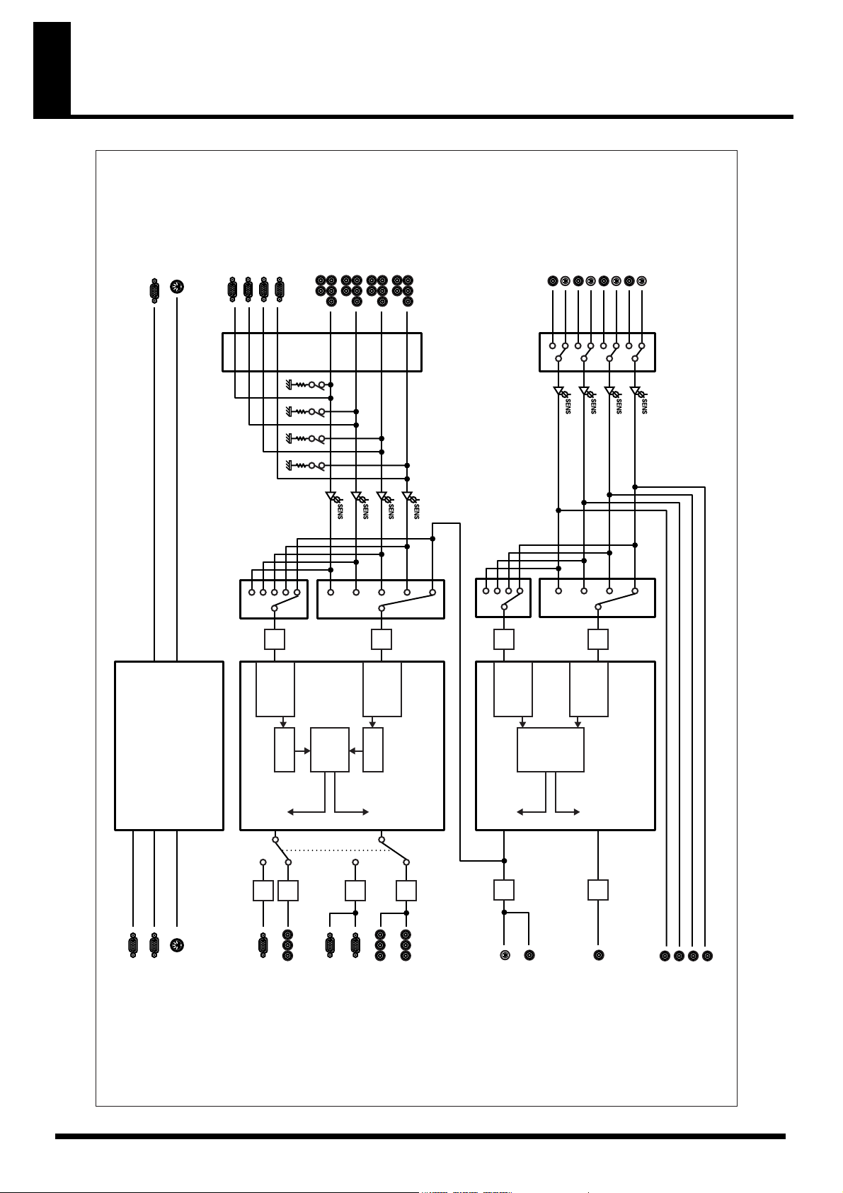
Block Diagram
HD/RGB IN 1 (D-Sub)
HD/RGB IN 2 (D-Sub)
HD/RGB IN 3 (D-Sub)
HD/RGB IN 4 (D-Sub)
CONTROL
(RS-232C)
MIDI IN
HD/RGB IN 4
(Component)
HD/RGB IN 3
(Component)
(Component)
HD/RGB IN 1
HD/RGB IN 2
(Component)
SD IN 3
SD IN 4
SD IN 4 (S-Video)
(Composite)
(Composite)
SD IN 3 (S-Video)
SD IN 1
SD IN 2
SD IN 2 (S-Video)
(Composite)
(Composite)
V-440HD Block Diagram
SD IN 1 (S-Video)
MIDI IN
CONTROL
Frame
Synchronizer
MIDI / SERIAL
A/D
D-BUS
Scaler
Effect
A/D
C-BUS
Frame
Synchronizer
Scaler
Auto Detection
Video Input
A/D
Synchronizer
HD/RGB MIXER
B-BUS
Frame
Effect
A/D
A-BUS
Frame
Synchronizer
Auto Detection
Video Input
SD MIXER
TALLY OUT
(HD/RGB)
TALLY HD
(SD)
TALLY SD
TALLY OUT
MIDI OUT
MIDI OUT / THRU
PREVIEW
OUT
D/A
D/A
HD PREVIEW OUT
(Component)
RGB PREVIEW OUT
(D-Sub)
RGB OUT 2
(D-Sub)
D/A
RGB OUT 1
(D-Sub)
PGM
OUT
(Component)
HD OUT 2
(Component)
D/A
PREVIEW
PGM
OUT
D/A
HD OUT 1
SD OUT
(S-Video)
SD OUT (Composite)
(OSD)
OUT
D/A
SD PREVIEW OUT
SD MONITOR OUT 3 (Composite)
SD MONITOR OUT 4 (Composite)
SD MONITOR OUT 1 (Composite)
SD MONITOR OUT 2 (Composite)
67
Page 68

Settings and Parameters
HD Size16:9 Output
Use the V-440HD’s component output for shows and other situations where the video is being output to plasma displays or high-
definition projectors.
HD Video Output Device
HD Camera
Component
Cable
Component
Cable
Final Output (HD)
Plasma Display or Other Display
RGB Video Output Device
PC or Other Device
D-Sub
Cable
SD Video Output Device
DV Camera, Player, Etc.
Composite
Cable
V-440HD Settings Parameters
Set the following parameters from the menu. Make parameter settings suited for the particular usage environment.
Settings Parameter Related Page
1. HD/RGB Output 1. Output Format |1080i| sw,
etc.
5. Zooming Set value to 100 when entire screen is not
2. HD/RGB Input 3. Pre Scaling Mode There are times when the RGB video is not
4. Manual Pre Scaling
5. Scaling Type
(Channel input to RGB and
Channel A/B only)
3. System 1. System Frame Rate Select the format appropriate for the out-
Selects optimal format, e.g., 1080i or 720p,
for the connected device.
being displayed.
displayed on the entire screen. Set the “3.
Pre Scaling Mode” to Manual and adjust
with the “4. Manual Pre Scaling” parameter.
As the aspect ratio of the video in the RGB
and SD sections (Channel A/B) is not 16:9,
set this to “Fixed Aspect: Letter” or “Fixed
Aspect: Crop.”
put device you are using.
p. 26
p. 48
p. 27
p. 49
p. 26
* For more on the menus, refer to Menu Operations (p. 25).
Settings Parameters for Devices Other Than V-440HD
It may be necessary to set the following parameters for connected plasma displays or high-definition projectors.
Settings Parameter Values
Output Device (e.g., plasma display, high-definition projector)
Set the input to “Component Input.”
68
Page 69

RGB Video Live Output
In business presentations and other such situations, use the V-440HD’s RGB output when outputting video to a data projector.
Settings and Parameters
HD Video Output Device
HD Camera
Component
Cable
Component
Cable
Final Output (RGB)
Projector or Other Display
RGB Video Output Device
PC or Other Device
D-Sub
Cable
SD Video Output Device
DV Camera, Player, Etc.
Composite
Cable
V-440HD Settings Parameters
Set the following parameters from the menu. Make parameter settings suited for the particular usage environment.
Settings Parameter Related Page
1. HD/RGB Output 1. Output Format |RGB| Sw,
etc.
5. Zooming Set value to 100 or lower when entire screen is not
2. HD/RGB Input 3. Pre Scaling Mode There are times when excess video is displayed
4. Manual Pre Scaling
5. Scaling Type As RGB video features various differing aspect
Selects optimal format, e.g., 1280 x 1024/60 to 640
x 480/60, for the connected device.
being displayed, adjusting as you observe the
screen being displayed.
on the screen. In such cases, Set the “3. Pre Scaling Mode” to Manual and adjust with the “4.
Manual Pre Scaling” parameter.
ratios, such as 4:3 and 16:9, it may be necessary to
adjust the aspect ratio while observing the
screen. If satisfactory results cannot be obtained
with “Full Size,” “Fixed Aspect: Letter,” or
“Fixed Aspect: Crop,” select “Manual” and make
fine adjustments to the “6. Manual X Scale” and
“7. Manual Y Scale” parameters.
p. 26
p. 48
p. 27
p. 49
* For more on the menus, refer to Menu Operations (p. 25).
Settings Parameters for Devices Other Than V-440HD
It may be necessary to set the following parameters for the data projector.
Settings Parameter Values
Output Device (e.g., data projector, computeruse liquid crystal display)
Set the input to “RGB Input.”
Switch off if the screen features a 16:9 wide output function.
69
Page 70

Settings and Parameters
SD Size4:3 Output
In shows and other situations where SD video is being output to LED displays or similar displays, you can output video from the V-
440HD’s HD OUT connectors.
* Only the resulting composite video from the SD section is output from the V-440HD’s SD PGM OUT connectors.
HD Video Output Device
HD Camera
Component
Cable
Component
Cable
Final Output (HD)
LED Display or Other Display
PC or Other Device
RGB Video Output Device
D-Sub
Cable
SD Video Output Device
DV Camera, Player, Etc.
Composite
Cable
V-440HD Settings Parameters
Set the following parameters from the menu. Make parameter settings suited for the particular usage environment.
Settings Parameter Related Page
1. HD/RGB Output 1. Output Format |1080i| Sw,
etc.
2. HD/RGB Input 3. Pre Scaling Mode There are times when excess portions of the HD video
4. Manual Pre Scaling
5. Scaling Type (Channel input
to RGB and Channel A/B only)
13. System 1. System Frame Rate Select the format appropriate for the output device you
Selects optimal format, e.g., 480/60p or 480/60i, for the
output device.
* When “1. System Frame Rate” below is set to 50-PAL,
this parameter can be set to 480/60p or 480/60i.
may be displayed. In such cases, set the “3. Pre Scaling
Mode” to Manual and adjust with the “4. Manual Pre
Scaling” parameter.
There may be instances where the aspect ratio of video
input with HD or RGB is not 4:3. If satisfactory results
cannot be obtained even when this is set to “Full Size,”
“Fixed Aspect: Letter,” or “Fixed Aspect: Crop,” select
“Manual” and make fine adjustments to the “6. Manual
X Scale” and “7. Manual Y Scale” parameters.
are using.
p. 26
p. 48
p. 27
p. 49
p. 26
p. 54
* For more on the menus, refer to Menu Operations (p. 25).
Settings Parameters for Devices Other Than V-440HD
It may be necessary to set the following parameters for the connected LED display being used.
Settings Parameter Values
Output Device (e.g., LED display) Set the input to “Component Input.”
70
Page 71

HD-SDI Recording
When recording the V-440HD’s video output with an HD CAM deck, DVC PRO HD deck, HD non-linear editing device, or other
such equipment, it may be necessary to convert the V-440HD’s component output to HD-SDI signals. For this, you will need to obtain
a separate HD HD-SDI converter to convert the component signals to HD-SDI.
Settings and Parameters
HD Video Output Device
HD Camera
Component
Cable
Component
Cable
RGB Video Output Device
PC or Other Device
Cable
HD HD-SDI Converter
SD Video Output Device
DV Camera, Player, Etc.
D-Sub
BNC Cable
Composite
Cable
SD Video Deck (HD-SDI)
V-440HD Settings Parameters
Set the following parameters from the menu. Make parameter settings suited for the particular usage environment.
Settings Parameter Related Page
1. HD/RGB Output 1. Output Format |1080i| Sw,
etc.
5. Zooming Set to 100.
2. HD/RGB Input 3. Pre Scaling Mode There are times when the RGB video is not
4. Manual Pre Scaling
5. Scaling Type (RGB) As RGB video features various differing as-
13. System 1. System Frame Rate Select the format appropriate for the output
Selects appropriate format for the HD-SDI
converter being used.
displayed fully on the screen. Set the “3. Pre
Scaling Mode” to Manual and adjust with the
“4. Manual Pre Scaling” parameter.
pect ratios, such as 4:3 and 16:9, it may be necessary to adjust the aspect ratio while
observing the screen.
device you are using.
p. 26
p. 48
p. 27
p. 49
p. 26
p. 54
* For more on the menus, refer to Menu Operations (p. 25).
Settings Parameters for Devices Other Than V-440HD
It may be necessary to set the following parameters for connected HD recorder.
Settings Parameterr Values
HD HD-SDI Converters Sync Signal: Use internal sync signal*
HD Recorder Input Signal: HD-SDI signals*
* Indications may vary with the device used.
* If the above settings do not stabilize the video, input the Y signal from the V-440HD’s HD PGM OUT 2 connector to the converter’s “Sync
Input” connector.
Frame Rate: 59.94 Hz*
Sync Signal: Use internal sync signal*
71
Page 72

Troubleshooting
If the V-440HD does not function properly, first check the following
points before determining there is some malfunction. If after
checking these points the problem persists, consult the nearest
Roland Service Center or Roland dealer.
Video Output
Video not being output
Confirm that the connected video device is properly connected as
described in “Making the Connections” (p. 20). If the connections
are correct, check the following points.
• Appropriate format for video device not selected
Check to confirm whether or not the output selected is suited for the
video device connected to the HD/RGB output connectors.
• Output connectors and output format not properly selected
If the video device is connected to the HD OUT connectors, confirm
that 1080i or 720p is selected with the OUTPUT FORMAT button. If
the video device is connected to the RGB OUT connectors, confirm
that RGB is selected with the OUTPUT FORMAT button.
Video output is disrupted
• Final output not locked
Changing the V-440HD’s output format settings may prevent
locking of the video with the device receiving the video. If this
occurs, try turning off the power to all devices, then turning on the
power to the transmitting device (e.g., video deck), the V-440HD,
and the receiving video device, in that order.
• Video output incompatible with receiving device
If the video output from the V-440HD is in a format that is not
compatible with the receiving device (such as a television monitor
or projector), the receiving device may be unable to output images
well. After confirming the formats compatible with the receiving
device, set the video output in the menu (p. 24).
• Reference signal (black burst signal) properly connected to
device requiring it
The V-440HD does not input or output reference signals (black burst
signals), thus video images may become disrupted when the
reference signals are connected to devices that require them. If this
occurs, use the following methods of avoiding disruption of the
video images.
• Input the signals output from the V-440HD’s HD OUTPUT
connector 2 Y connector to the reference signal input connector
on the device requiring reference signals.
• Switch the device requiring the reference signal to a mode that
uses reference signals within the component signals.
Color of input video is incorrect
As the V-440HD inputs and outputs HD, RGB, and SD signals as
analog signals, differences in individual devices can lead to color
variance, even with the same video sources. Correct these
differences with “2. HD/RGB Input” (p. 49) in the menu.
• Mistake in BNC connector used for inputting component video
When inputting component signals, connecting to the wrong BNC
connectors may result in video being displayed monochrome image.
Confirm that the connections to each BNC connector are correct.
Video images input to HD/RGB are disrupted
• Video being input with differing System Frame Rate settings (p. 42)
When the video format uses a different frame rate than the system
frame rate set for the V-440HD, the video image may at times move
in a disjointed fashion due to the frame rate conversion processing
required.
• Video being input with frame rate different than that for the
output format (p. 26)
When the video format uses a different frame rate than the frame
rate set for the V-440HD’s output format, the video image may at
times move in a disjointed fashion due to the frame rate conversion
processing required.
Aspect ratio of video input using RGB
signals is off
• Settings not matching screen’s aspect ratio
In some instances, the screen aspect ratio of the device to which the
finished video images are being input may not match the aspect
ratio of the RGB input video. Make the settings selected in the menu
(p. 24) to achieve the proper aspect ratio.
• RGB input’s horizontal synchronization set to rate other than 60
Hz or 75 Hz
If the horizontal synchronization of the RGB video is not properly
matched to the 60 or 75 settings, the video image will be extended
vertically as a result.
• Does the signal conform to VESA standards?
• The RGB signal output of some devices may not properly
conform to VESA standards. When such signals are used, the
screen image may be extended vertically or horizontally as a
result.
If this occurs, you can adjust the aspect ratio of the RGB video
images by setting “6. Manual X Scale” and “7. Manual Y Scale”
under "2. HD/RGB Input" (p. 49) in the menu.
Screen shows visible vertical
discrepancies
Video input to the HD/RGB IN connectors is disrupted
• Instability of the video
Depending on the condition of the video signals input to the V440HD, the video image may become very unstable when the C-BUS
or D-BUS channel buttons are used to switch the video (when the
lock is off). If this occurs, go to "2. HD/RGB Input" (p. 49) in the
menu and set "1. Format Auto Detect" to "Manual," then select the
video to be input with "Input Format."
• Video being input to the BNC and D-Sub connectors on the
same channel
Inputting two video sources to the same channel creates interference
in the internal circuitry, resulting in disruption of the images. Input
video sources to different channels.
The screen aspect ratio may be distorted if the format of the output
video does not match the settings of the device receiving HD output
or RGB output.
Not all of the video appearing in the screen
Some receiving devices may not display all of the video output from
the V-440HD. This may be due to differences in the size of the
region in which video is not displayed (the safe area) in some
receiving devices. To adjust the video size so that it does not reach
into the safe area, set “4. Zooming” under “1. HD/RGB Output” in
the menu.
72
Page 73

Troubleshooting
Effects Operations in Individual Sections
Screen is disrupted when video is switched
• When using transition, P in P, or key composite effects
Disruption of the video images may occur when the video is
switched with the A-BUS (B-BUS) SD IN select buttons or the C-BUS
(D-BUS) HD/RGB IN select buttons. Switch the video after first
stopping the effect.
Subscreen not displayed when P in P
is used
• Subscreen positioned near the edge of the screen
When setting the subscreen position with the POSITION joystick or
by other means, most of the subscreen may end up outside of the
screen itself. If this occurs, the subscreen will not appear in the
screen. In such instances, use the POSITION joystick to move the
subscreen back to a position where it is visible.
• When using the Multi Screen function
When the Multi Screen function (p. 39) is used, part of the screen is
expanded when displayed. In this case, the subscreen portion does
not expand, and as a result, the subscreen may cease to appear. If
this occurs, use the POSITION joystick to move the subscreen back
to a suitable position.
Video image not being removed
properly with the key effects
Adjust the value of the “Soft Edge” setting in the menu. If the value
is set too high, portions of the video not belonging to the key image
may also end up being masked.
Use video input that features a high signal-to-noise ratio. For
example, you can achieve better key composite results with HD key
images than with SD key images.
• When using the Multi Screen function
When the Multi Screen function (p. 39) is used, the key composite
conditions of the master and slave V-440HDs may differ.
This is because the video input for these V-440HDs comprises
analog signals, with the resulting differences in video signals being
the physical cause of this problem.
To mitigate these conditions, adjust the “Brightness” and “Contrast”
parameters with "2. HD/RGB Input" (p. 49) and "7. SD Input" (p. 51)
while using the key composite effects, adjusting each V-440HD so
that the same video is synthesized.
* When using the Multi Screen function, the LEVEL knob function is
linked to the master and slave devices, so you should lock in a fixed
value.
Screen is disrupted when video is switched
• When using transition, P in P, or key composite effects
Disruption of the video images may occur when the video is
switched with the A-BUS (B-BUS) SD IN select buttons or the C-BUS
(D-BUS) HD/RGB IN select buttons. Switch the video after first
stopping the effect.
Video fader not operating properly
• Video fader calibration setting seems to be wrong
With time and extended use, the settings for the video faders’ top
and bottom positions may drift into inaccuracy. If this occurs, adjust
the video faders (p. 54) with the settings in "13. System" (p. 54) in the
menu.
No movement when POSITION
joystick adjusted
The P in P position may fail to move even when the POSITION
joystick is adjusted. If this occurs, check the LOCK button next to the
POSITION joystick to see whether or not the button is lit. If the
button is lit, it indicates that the POSITION button is locked, which
prevents the POSITION joystick from functioning. To enable
operation of the POSITION joystick, press the LOCK button so its
light is off.
Other
V-440HD becoming hot
• Something is blocking the exhaust vent or ventilation port
The V-440HD is cooled with forced air, so if anything impeding the
exhaust vent or any other air flow intake or vent, it will prevent
proper cooling of the V-440HD.
• Other equipment is stacked on top of the V-440HD
Setting other devices directly on top of the V-440HD may result in
heat from these devices being transferred to the V-440HD, thus
causing the V-440HD to overheat. In such situations, either raise the
other device upwards away from the V-440HD or provide shelving
or racks placed between the devices.
Odd noises coming from inside the unit
• Debris is caught in the exhaust vent
The V-440HD is cooled with forced air, using a cooling fan installed
inside the exhaust vent. If anything caught up in cooling fan, it can
cause audible noises from the interior of the V-440HD, and may
even lead to damage. Do not place any objects liable to enter the
exhaust vent near the vent.
If something does get inside the exhaust vent and you are unable to
remove it from the outside, contact the nearest Roland Service
Center.
73
Page 74

Memo
Menu Settings Memo
1. HD/RGB Output
1: Output Format (1080i ) Sw
2: Output Format (720p) Sw
3: Output Format (RGB) Sw
4: Output Format Sw Lock
5: Zooming
6: Bright
7: Contrast
8: Saturation
9: Red
10: Green
11: Blue
12: Output Fade Mode
13: Output Fade Color
14: Test Pattern Select
2. HD/RGB Input
(HD/RGB Ch) A/B 1 2 3 4
1: Format Auto Detect
2: Input Format
3: Pre Scaling Mode
4: Manual Pre Scaling
5: Scaling Type
6: Manual X Scale
7: Manual Y Scale
8: X Position
9: Y Position
10: Brightness
11: Contrast
12: Saturation
13: Red
14: Green
15: Blue
16: Frequency
17: Phase
3. HD/RGB P in P / Zoom
(HD/RGB PinP) 1 2 3 4 5
1: Size
2: X Position
3: Y Position
4: Zoom
5: Pan X Position
6: Pan Y Position
7, Border Size
8: Border Color
9: Border Edge
4. HD/RGB Key
1: Key Type
2: Key Level
3: Key Soft Edge
5. HD/RGB Wipe Select
(HD/RGB Wipe Sw)
1: Wipe Pattern
2: Wipe Reverse
3: Wipe Edge Type
1 2 3 4 5 6
6. SD Output
1: Brightness
2: Contrast
3: Cb
4: Cr
5: Saturation
6: Color Bar
7. SD Input
(SD Wipe Sw)
1: Input Select
2: Brightness
3: Contrast
4: Color
5: Hue
A/B 1 2 3 4 6
74
Page 75

Memo
8. SD PinP
(Size) 1 2 3 4 5
1: Size
2: X Position
3: Y Position
4: Border Size
5: Border Color
6: Trimming
9. SD Key
1: Key Type
2: Key Level
3: Key Soft Edge
10. SD Wipe Select
(SD Wipe Sw) 1 2 3 4 5 6
1: Wipe Pattern
2: Wipe Reverse
3: Wipe Edge Type
11. Panel Preset Edit
1: Copy
2: Exchange
12. Multi Screen
1: Multi Screen On/Off
2: Multi Screen Type
3: Multi Screen ID
(Screen) 1
(Master)2(Slave)3(Slave)4(Slave)5(Slave)6(Slave)
1: X Size
2: Y Size
3: X Position
4: Y Position
13. System
1: System Frame Rate
2: SD Deinterlacer
3: SD Input Sync Threshold
4: SD V-FdrCaribrate A
5: SD V-FdrCaribrate B
6: HD/RGB V-FdrCaribrate C
7: HD/RGB V-FdrCaribrate D
8: REMOTE Baudrate
9: HD Seamless Delay Time
10: SD Seamless Delay Time
11: HD On Screen Display
12: Tally Signal
13: SD Previewout Select
14: Memory Protect
14. MIDI Setup
1:MIDI Sw Mode
2:MIDI Tx Channel
3:MIDI Rx Channel
4:MIDI Out/Thru Switch
5:V-LINK Switch
6:Device ID
7:Panel Preset Tx Type
8:SD Auto Sw Assign
9:SD Transition Assign
10:SD Transition Time
11:SD Video Fader Assign
12:SD Key Sw Assign
13:SD P in P Sw Assign
14:
SD P in P Lock Sw Assign
15:HD Auto Sw Assign
16:HD Transition Assign
17:HD Transition Time
18:HD Video Fader Assign
19:HD Key Sw Assign
20:HD P in P Sw Assign
21:
HD P in P Lock Sw Assign
22:P in P/Zoom Sw Assign
23:Panel Peset Sw Assign
24:
Output Format Sw Assign
25:Fade Sw Assign
26:Fade Level Assign
75
Page 76
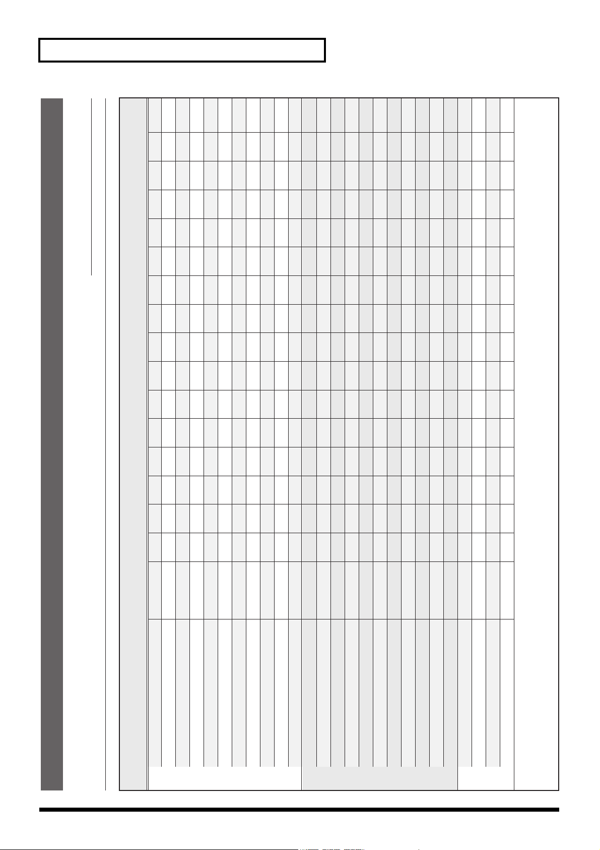
Memo
Date:
No.
p. 35
p. 36
p. 37
p. 37
p. 52
p. 52
p. 35
p. 35
p. 34
p. 34
p. 34
p. 30
p. 31
p. 33
p. 32
p. 50
p. 50
p. 29
p. 29
p. 28
p. 28
p. 28
p. 48
p. 50
p. 40
p. 40
5
1
4
1
3
1
2
1
1
1
0
1
12345 678 9
Panel Preset Button No.
Off
Factory Preset
Configurations of panel controller settings
Panel Preset Memo
Title:
ON
P in P PATTERN Buttons (SD)
P in P LOCK Button (SD)
SD Section HD/RGB Section
76
128
Off
Luminance Key2
KEY LEVEL Knob (SD)
KEY ON Button (SD)
Key Type (SD)
03
1 ch
2 ch
1.0
A-BUS
MIX
Key Soft Edge (SD)
A-BUS Channel Button (SD)
B-BUS Channel Button (SD)
TIME Knob (SD)
Video Fader (SD)
TRANSITION Button (SD)
Off
ON
128
Off
Luminance Key2
03
1 ch
P in P PATTERN Buttons (HD/RGB)
P in P LOCK Button (HD/RGB)
KEY LEVEL Knob (HD/RGB)
KEY ON Button (HD/RGB)
Key Type (HD/RGB)
Key Soft Edge (HD/RGB)
A-BUS Channel Button (HD/RGB)
2 ch
1.0
C-BUS
MIX
Auto
128
Off
1 x 1
B-BUS Channel Button (HD/RGB)
TIME Knob (HD/RGB)
Video Fader (HD/RGB)
TRANSITION Button (HD/RGB)
OUTPUT FADE MODE
OUTPUT FADE LEVEL
Multi Screen On/Off
Multi Screen Type
Others
Memo :
Page 77

Index
A
A-BUS Channel Button (SD) ........................................ 14
AC Inlet ........................................................................... 18
AUTO Button (HD/RGB) ............................................ 17
AUTO Button (SD) ........................................................ 15
B
B-BUS Channel Button (SD) ........................................ 14
C
C-BUS Channel Button (HD/RGB) ............................ 16
D
D-BUS Channel Button (HD/RGB) ............................ 17
E
ENTER Button ............................................................... 17
ENTER button ................................................................ 24
Exhaust Vent .................................................................. 18
F
fade-in ............................................................................. 23
Fade-out .......................................................................... 23
G
Ground terminal ............................................................ 18
H
HD OUT 1, 2 Connectors (Analog Component) ....... 19
HD PREVIEW Connector (Analog Component) ...... 19
HD/RGB 75 ohm TARMINATOR Switch 1-4 .......... 19
HD/RGB IN 1-4 Connectors (Analog Component/
RGB) ................................................................................ 19
HD/RGB IN 1-4 Connectors (RGB/Analog
Component) ................................................................... 19
HD/RGB IN Button ...................................................... 12
HD/RGB Input Section ................................................ 18
HD/RGB Output Section ............................................. 18
HD/RGB Section ........................................................... 13
K
KEY Button (HD/RGB) ................................................ 16
KEY Button (SD) ............................................................ 14
M
menu ................................................................................ 24
MENU Button ................................................................ 17
MENU button ................................................................ 24
MIDI Button ................................................................... 12
MIDI IN Connector ....................................................... 18
MIDI OUT/THRU ......................................................... 18
O
OUTPUT FADE Button ................................................ 13
OUTPUT FADE button ................................................ 23
OUTPUT FORMAT Button .......................................... 12
P
P in P Button (HD/RGB) .............................................. 16
P in P PATTERN Button (HD/RGB) .......................... 16
P in P PATTERN Button (SD) ...................................... 14
PAN/ZOOM Button (HD/RGB) ................................ 16
PANEL PRESET Button ................................................ 17
POSITION Joystick (SD) ............................................... 14
POSITION/PAN Joystick (HD/RGB) ........................ 16
POWER Switch .............................................................. 18
POWER switch ............................................................... 23
R
REMOTE Connector ..................................................... 18
RGB OUT 1, 2 Connectors (Analog RGB) .................. 19
RGB PREVIEW Connectors (Analog RGB) ............... 19
S
SD IN Buttons ................................................................ 12
SD Input/Output Section ............................................. 18
SD MONITOR OUT Output 1-4 Connectors (Analog
Composite Video) .......................................................... 19
SD PREVIEW OUT connector ..................................... 24
SD Section ....................................................................... 13
SECURITY Slot .............................................................. 18
Settings Section .............................................................. 12
SHIFT Button ................................................................. 17
SIZE Knob (SD) .............................................................. 14
SIZE/ZOOM Knob (HD/RGB) ................................... 16
L
LEVEL Display (HD/RGB) .......................................... 16
LEVEL Display (SD) ..................................................... 14
LEVEL Knob (HD/RGB) .............................................. 16
LEVEL Knob (SD) ......................................................... 14
LOCK Button (HD/RGB) ............................................. 16
LOCK Button (SD) ........................................................ 14
T
TALLY Terminal ............................................................ 18
TIME Display (HD/RGB) ............................................ 16
TIME Display (SD) ........................................................ 14
TIME Knob ..................................................................... 13
TIME knob ...................................................................... 23
TIME Knob (HD/RGB) ................................................ 16
77
Page 78

Index
TIME Knob (SD) ............................................................ 14
TRANSITION Button (HD/RGB) ............................... 17
TRANSITION Buttons (SD) ......................................... 15
TRANSITION Indicator (HD/RGB) ........................... 17
TRANSITION Indicator (SD) ...................................... 14
V
VALUE Knob ................................................................. 17
VALUE knob .................................................................. 25
Video Fader (HD/RGB) ............................................... 17
Video Fader (SD) ........................................................... 15
78
Page 79

Main specifications
V-440HD: MULTI FORMAT VIDEO MIXER
Video Processing
Video Format: SD NTSC or PAL [CVBS, S (Y/C)]
HD 1080/59.94i/50i SMPTE274M (Y/Pb/Pr TriLevel Sync)
720/59.94p/50p SMPTE296M (Y/Pb/Pr TriLevel Sync)
PC-RGB 640x480/60/75, 800x600/60/75, 1024x768/60/75,1280x768/60/75,
1280x1024/60 (RGB VH:positive/negative logic)
* VESA DMT Version 1.0 Revision 10 conform
Video Sampling Rate: SD 4:2:2 (Y/Cb/Cr) 8-bit 13.5 MHz (BT.601)
HD 4:4:4 (Y/Pb/Pr) 8-bit 74.1758 MHz / 74.25 MHz
RGB 4:4:4 (R/G/B) 8-bit 25 MHz to 110 MHz
Effects Video Transition Cut
Dissolve
Wipe: 6 Patterns, Reverse, SoftEdge
Composition FX Picture in Picture,
Chroma Key (Blue/Green),
Luminance Key(White/Black)
Picture in Picture with Zoom/Pan (HD/RGB side)
Multi-Screen Presentation Screen Setup: 2 screens x 1 line, 3 screens x 1 line, 2 screens x 2 line,
3 screens x 2 lines
Synchronization Multiple Units by MIDI
Master Fade 0 to 4 seconds Black or White
Connectors
SD Input S-Video (Y/C) Preferential x 4: 4 pin mini DIN type (Y: 1.0 Vp-p, C: 0.286 Vp-p, 75 ohms)
Video (composite)x 4 BNC type (1.0 Vp-p, 75 ohms)
HD/RGB Input BNC Type x 4 HD: Y/Pb/Pr (1.0 Vp-p, 75 ohms, TriLevel Sync)
RGB:R/G/B (0.7 Vp-p, 75 ohms), H (5VTTL), V (5VTTL)
D-SUB 15pin Shrink Type x 4
* BNC Type or D-sub Type are
In/ThruOut Use combinedly
SD Output PGM S-Video (Y/C) 4-pin mini DIN type (Y: 1.0 Vp-p, C: 0.286 Vp-p, 75 ohms)
PGM Video (composite) BNC type (1.0 Vp-p, 75 ohms)
Preview BNC type (1.0 Vp-p, 75 ohms), OSD Menu Output
HD Output PGM Component HD BNC Type x 2 (1.0 Vp-p, 75 ohms, TriLevel Sync)
Preview Component HD BNC type (1.0 Vp-p, 75 ohms, TriLevel Sync),
OSD Menu Output (selectable Display)
RGB Output PGM RGB D-sub 15 pin Shrink Type x 2 (0.7 Vp-p, 75 ohms, 5 VTTL Sync)
Preview RGB D-sub 15 pin Shrink type (0.7 Vp-p, 75 ohms, 5 VTTL Sync),
Remote Control Interfaces MIDI 5 pin DIN Type (In, Out/Thru)
RS-232C D-sub 9pin
TALLY Output for SD Section D-sub 15 pin Shrink type
for HD Section D-sub 15 pin Shrink type
Others
Power Supply AC 117 V, AC 230 V, AC 240 V (50/60 Hz)
AC 220 V (60 Hz)
Power Consumption 50 W
Dimensions 482 (W) x 308 (D) x 130 (H) mm
19 (W) x 12-1/8 (D) x 5-1/8 (H) inches
* EIA-7U Rack Mount Size
Weight 6.8 kg
15 lbs
Accessories Owner’s Manual, Power Cord
HD: Y/Pb/Pr (1.0 Vp-p, 75 ohms, TriLevel Sync)
RGB:R/G/B (0.7 Vp-p, 75 ohms), H (5VTTL), V (5VTTL)
OSD Menu Output (selectable Display)
* Component & RGB Outputs are selectable
Input(max): 12 V, 200 mA Open collector Type
Input(max): 12 V, 200 mA Open collector Type
* In the interest of product improvement, the specifications and/or appearance of this unit are subject to change without prior notice.
79
Page 80

Information
When you need repair service, call your nearest EDIROL/Roland Service Center or authorized EDIROL/Roland distributor
in your country as shown below.
ASIA
CHINA
Roland Shanghai Electronics Co.,Ltd.
5F. No.1500 Pingliang Road
Shanghai 200090, CHINA
TEL: (021) 5580-0800
Roland Shanghai Electronics Co.,Ltd.
(BEIJING OFFICE)
10F. No.18 3 Section Anhuaxili
Chaoyang District Beijing
100011 CHINA
TEL: (010) 6426-5050
Roland Shanghai Electronics Co.,Ltd.
(GUANGZHOU OFFICE)
2/F., No.30 Si You Nan Er Jie Yi
Xiang, Wu Yang Xin Cheng,
Guangzhou 510600, CHINA
TEL: (020) 8736-0428
TAIWAN
ROLAND TAIWAN
ENTERPRISE CO., LTD.
Room 5, 9fl. No. 112 Chung Shan
N.Road Sec.2, Taipei, TAIWAN,
R.O.C.
TEL: (02) 2561 3339
SINGAPORE/
MALAYSIA
Roland Asia Pacific Sdn. Bhd.
45-1, Block C2, Jalan PJU 1/39,
Dataran Prima, 47301 Petaling
Jaya, Selangor, MALAYSIA
TEL: 3-7805-3263
CENTRAL/LATIN
AMERICA
Roland Systems Group U.S.
14830 Desman Road, La Mirada,
CA 90638 U.S.A.
TEL: 714-521-8000
EUROPE
AUSTRIA/GERMANY/
ITALY/IRELAND/
UNITED KINGDOM
EDIROL (Europe) Ltd.
Studio 3.4 114 Power Road
London W4 5PY
U. K.
TEL: (0)20 8747 5949
BELGIUM/FRANCE/
LUXEMBOURG/
SWITZERLAND/
HOLLAND/SPAIN/
PORTUGAL
Roland Iberia, S.L.
Paseo Garca Faria, 33-35
08005 Barcelona SPAIN
TEL: 93 493 91 00
DENMARK
Roland Scandinavia A/S
Nordhavnsvej 7, Postbox 880,
DK-2100 Copenhagen
DENMARK
TEL: 3916 6200
FINLAND
Roland Scandinavia As,
Filial Finland
Elannontie 5
FIN-01510 Vantaa, FINLAND
TEL: (0)9 68 24 020
NORWAY
Roland Scandinavia Avd.
Kontor Norge
Lilleakerveien 2 Postboks 95
Lilleaker N-0216 Oslo
NORWAY
TEL: 2273 0074
SWEDEN
Roland Scandinavia A/S
SWEDISH SALES OFFICE
Danvik Center 28, 2 tr.
S-131 30 Nacka SWEDEN
TEL: (0)8 702 00 20
HUNGARY
Roland East Europe Ltd.
Warehouse Area DEPO Pf.83
H-2046 Torokbalint, HUNGARY
TEL: (23) 511011
CZECH REP.
K-AUDIO
Kardasovska 626.
CZ-198 00 Praha 9,
CZECH REP.
TEL: (2) 666 10529
GREECE
STOLLAS S.A.
Music Sound Light
155, New National Road
Patras 26442, GREECE
TEL: 2610 435400
POLAND
MX MUSIC SP.Z.O.O.
UL. Gibraltarska 4.
PL-03664 Warszawa POLAND
TEL: (022) 679 44 19
ROMANIA
FBS LINES
Piata Libertatii 1,
535500 Gheorgheni, ROMANIA
TEL: (266) 364 609
RUSSIA
MuTek
Dorozhnaya ul.3,korp.6
117 545 Moscow, RUSSIA
TEL: (095) 981-4967
UKRAINE
TIC-TAC
Mira Str. 19/108
P.O. Box 180
295400 Munkachevo, UKRAINE
TEL: (03131) 414-40
OCEANIA
Roland Corporation
Australia Pty., Ltd.
38 Campbell Avenue
Dee Why West, NSW 2099
AUSTRALIA
For Australia
Tel: (02) 9982 8266
For New Zealand
Tel: (09) 3098 715
NORTH AMERICA
CANADA
Roland Canada Music Ltd.
(Head Office)
5480 Parkwood Way, Richmond
B. C., V6V 2M4 CANADA
TEL: (604) 270 6626
Roland Canada Music Ltd.
(Toronto Office)
170 Admiral Boulevard
Mississauga ON L5T 2N6
CANADA
TEL: (905) 362 9707
U. S. A.
Roland Systems Group U.S.
14830 Desman Road, La Mirada,
CA 90638 U.S.A.
TEL: 714-521-8000
* 040117701 -02 *
As of December 10, 2005 (EDIROL-2)
04017701 ’06-1-2N
 Loading...