

Page 1

Page 2

Contents
Main Features . . . . . . . . . . . . . . . . . . . . . . . . . . .3
Conrming Package Contents . . . . . . . . . . . .4
Panel Descriptions . . . . . . . . . . . . . . . . . . . . . . .6
Front Panel . . . . . . . . . . . . . . . . . . . . . . . . . . . . 6
Rear Panel . . . . . . . . . . . . . . . . . . . . . . 9
USB Driver Installation . . . . . . . . . . . . . . . . . 11
Install the USB Driver (Windows) . . . . . .11
Install the USB Driver (Mac OS X) . . . . . .13
Conrm that Sound Can Be Heard . . . .14
Basic Operation . . . . . . . . . . . . . . . . . . . . . . . . 16
Connecting Equipment . . . . . . . . . . . . . . .16
Turning the Power On/O . . . . . . . . . . . .16
Turning the Power On . . . . . . . . . .16
Turning the Power O . . . . . . . . . .17
Making the Power
Automatically Turn O After a
Time (Auto O) . . . . . . . . . . . . . . . . 17
Checking the Levels . . . . . . . . . . . . . . . . . .18
Adjusting the Audio Signals . . . . . . . . . .19
Adjusting the Mic Preamp and
Compressor . . . . . . . . . . . . . . . . . . . .19
Adjusting the Attenuator . . . . . . .22
Adjusting the Direct Monitor
Settings . . . . . . . . . . . . . . . . . . . . . . . .23
Setting Input and Output Device . . . . .25
Using the STUDIO-CAPTURE Control Panel 27
Internal Blocks of the STUDIO-CAPTURE 27
Starting the STUDIO-CAPTURE
Control Panel . . . . . . . . . . . . . . . . . . . . . . . .29
Controlling the Preamps and Mixers . . 30
Preamp Control Screen . . . . . . . . .30
Attenuator Screen . . . . . . . . . . . . . .32
Monitor Mixer Control Screen . . . 32
Patch Bay . . . . . . . . . . . . . . . . . . . . . . 37
Saving or Loading Settings on the
Computer . . . . . . . . . . . . . . . . . . . . . . . . . . . 38
Saving or Loading Compressor
Presets on the Computer . . . . . . . . . . . . .38
Changing the AUTO-SENS Settings. . . .39
Directly Outputting Each Channel’s
Input . . . . . . . . . . . . . . . . . . . . . . . . . . . . . . . .40
Synchronizing with Other Devices . . . . 41
Initializing the Settings . . . . . . . . . . . . . . .41
Checking the Signal Flow . . . . . . . . . . . . .41
USB Driver Settings . . . . . . . . . . . . . . . . . . . 42
View in Foreground . . . . . . . . . . . . . . . . . . 42
Changing the System Settings . . . . . . . . . . 43
Advanced Operation . . . . . . . . . . . . . . . . . . . 45
Outputting to Four Monitor Systems . .45
Connecting Two STUDIO-CAPTURE
Units . . . . . . . . . . . . . . . . . . . . . . . . . . . . . . . . .46
Synchronizing with Another Digital
Device . . . . . . . . . . . . . . . . . . . . . . . . . . . . . . .52
Appendices . . . . . . . . . . . . . . . . . . . . . . . . . . . . 53
Sampling Rate Setting . . . . . . . . . . . . . . . .53
Limitations When Using the 192 kHz
Setting . . . . . . . . . . . . . . . . . . . . . . . . . . . . . . .53
Restoring the Factory Settings
(Factory Reset) . . . . . . . . . . . . . . . . . . . . . . . 54
USB Driver Settings . . . . . . . . . . . . . . . . . . . 54
Mac OS X MIDI Settings . . . . . . . . . . . . . . .56
Troubleshooting . . . . . . . . . . . . . . . . . . . . . 59
USB Driver Installation . . . . . . . . . .59
Using the STUDIO-CAPTURE . . . .60
Problems When Two Units Are
Connected . . . . . . . . . . . . . . . . . . . . .66
Changing Computer Settings to
Avoid Problems . . . . . . . . . . . . . . . . . . . . . .68
Setting the System Volume . . . . .68
Voice Communication
Software Settings . . . . . . . . . . . . . .69
Monitoring Function Settings . . .69
Main Specications . . . . . . . . . . . . . . . . . . . . 70
USING THE UNIT SAFELY . . . . . . . . . . . . . . . . 72
IMPORTANT NOTES . . . . . . . . . . . . . . . . . . . . 75
Index . . . . . . . . . . . . . . . . . . . . . . . . . . . . . . . . . . 77
2
Page 3
Main Features
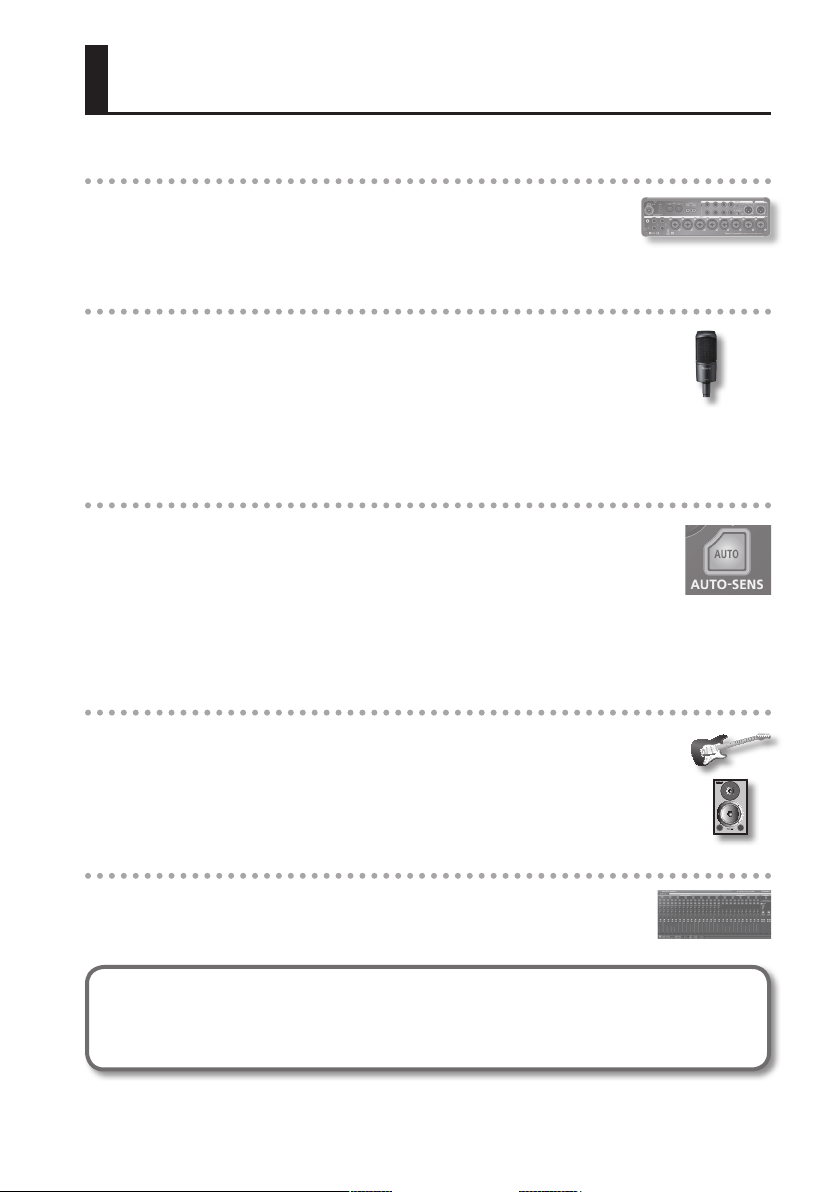
Simultaneously input 16 channels and output 10 channels
At 96/48/44.1 kHz, you can simultaneously input 16 channels and output 10
channels.
This allows you to use multi-mic setups to record acoustic drums or a band.
Twelve mic preamps allow recording with high audio quality
The STUDIO-CAPTURE comes equipped with twelve of the highly acclaimed
“VS PREAMP” mic preamps, which were designed to provide the highest
possible sound quality when they were introduced on the OCTA-CAPTURE.
Despite its compact body, the STUDIO-CAPTURE can capture the true sound
of your instruments and mics with astoundingly high audio quality.
A wide range of inputs are supported, and you can also connect a guitar.
AUTO-SENS automatically sets the optimal input level
The analog input jacks oer AUTO-SENS, which analyzes an instrument’s volume
and automatically sets the optimal input level.
After AUTO-SENS is turned ON, the input signal’s volume changes are analyzed
during a rehearsal for a xed length of time, allowing the signal to be recorded on
your DAW software at the optimal level. This is convenient for recording sessions
with limited setup time, and lets you avoid problems such as clipping due to inappropriate input
level settings.
Low-latency monitoring
The STUDIO-CAPTURE uses the same “VS STREAMING” audio streaming technology
that won broad acclaim when it was introduced on the OCTA-CAPTURE. Thanks to a
high degree of fusion between the driver and the hardware, we have been able to
keep monitoring latency during recording to an ultra-low level, and ensure stable
operation for the system.
Dedicated software allows settings from your computer
The dedicated “STUDIO-CAPTURE Control Panel” software lets you edit all of
the parameters. (Parameters not shown in the display of the STUDIO-CAPTURE
can also be edited.)
Before using this unit, carefully read the sections entitled “USING THE UNIT SAFELY” (p. 72) and “IMPORTANT
NOTES” (p. 75). These sections provide important information concerning the proper operation of the unit.
Additionally, in order to feel assured that you have gained a good grasp of every feature of your new unit, read
Owner’s Manual in its entirety. This manual should be saved and kept on hand as a convenient reference.
Copyright © 2013 ROLAND CORPORATION
All rights reserved. No part of this publication may be reproduced in any form without the written permission of
ROLAND CORPORATION.
3
Page 4

Conrming Package Contents
After you open the package, please check that all items are present.
If anything is missing, please contact the retailer from whom you purchased the unit.
STUDIO-CAPTURE
STUDIO-CAPTURE Driver CD-ROM
Contains USB drivers, and demo songs.
AC adaptor
This is the dedicated AC adaptor for the STUDIO-CAPTURE.
USB cable
Use this cable to connect the STUDIO-CAPTURE to the USB port of your computer.
* Please use only the included AC adaptor and USB cable. If you require a replacement due to
loss or damage, please contact the nearest Roland Service Center, or an authorized Roland
distributor, as listed on the “Information” page.
Owner’s Manual
This is the document you’re reading. Keep it on hand for reference when needed.
Block Diagram leaet
This shows the audio signal ow, and how the preamp (p. 30), monitor mixer (p. 32),
and patch bay (p. 37) are related.
License agreement
This agreement permits you to use software for which the copyright is owned by Roland
Corporation.
You must read this before opening the CD-ROM.
4
Page 5
Conrming Package Contents
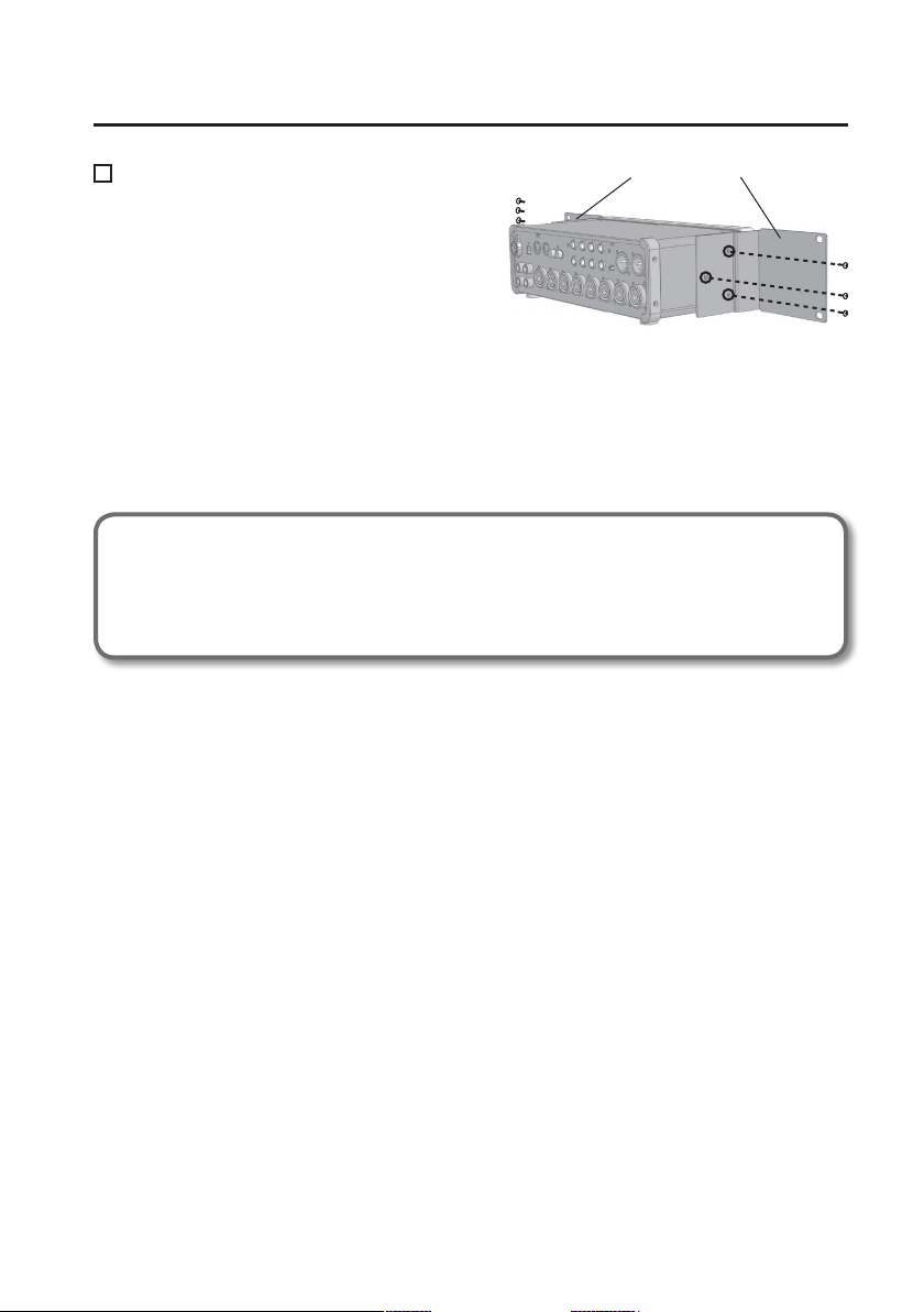
Rack mount angle
If you want to install the STUDIO-CAPTURE in an
19-inch rack, please use the included rack mount
adaptors.
Installation
Rack mount angle
1. Remove the screws from the left and right sides of the STUDIO-CAPTURE (three
screws on each side).
2. Fasten the rack mount adaptors to the STUDIO-CAPTURE using the screws you
removed in step 1.
Be sure to attach the rack mount adaptors using the screws you removed.
Items you’ll need to prepare
• External amplier, speakers, headphones, etc., for listening to the sound that is output
from the STUDIO-CAPTURE
• Microphone, guitar, etc., for inputting audio to the STUDIO-CAPTURE
5
Page 6
Panel Descriptions
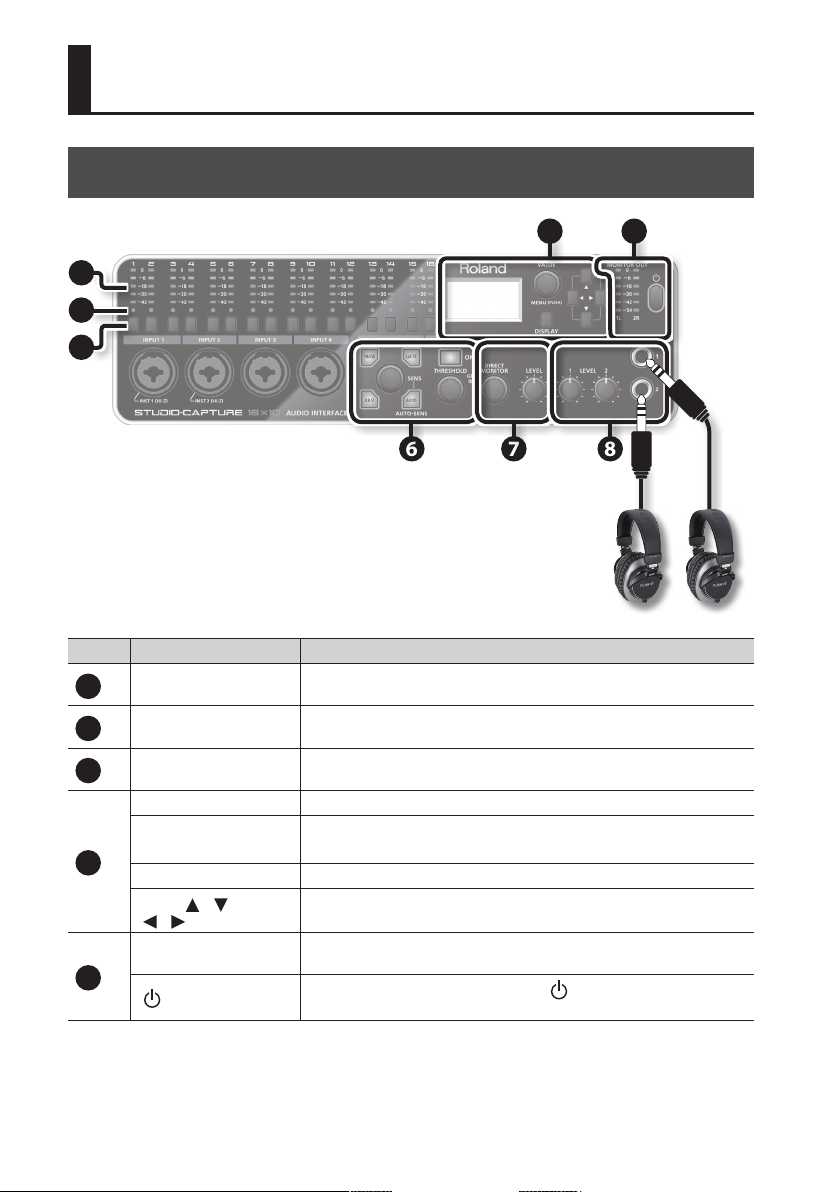
Front Panel
1
2
3
Number Name Explanation
Input level meters
1
Input channel indicators
2
Input channel buttons
3
Display This shows various information about the STUDIO-CAPTURE.
[VALUE] knob
([MENU] button)
4
[DISPLAY] button The main screen (p. 18) appears in the display.
Cursor [
[
MONITOR OUT level meter
] [ ]
] [ ] buttons
5
[
] (Power) button
These indicate the input levels of the 16 channels. Adjust the input level so
that the peak indicator (0; red LED) of each input level meter does not light.
These indicate the selected channel. You can edit the preamp settings of the
channel whose indicator is lit.
Press the button of the input channel for which you want to edit preamp,
compressor, or attenuator settings (p. 19, p. 22).
Turn this knob to edit the parameter value.
If you press this knob, the SYSTEM screen (p. 43) appears in the display.
These buttons move the cursor in the display.
This indicates the level of the audio signal immediately before the [MONITOR OUT LEVEL] knob (refer to the separate “Block Diagram“ leaet).
To turn the power on/o, hold down the [ ] (power) button for several
seconds (p. 16).
4 5
6 7 8
6
Page 7
Panel Descriptions
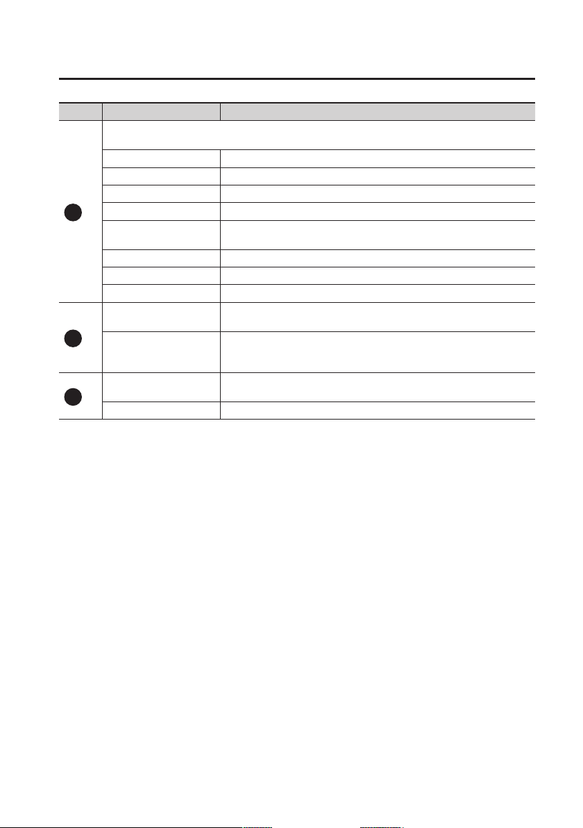
Number Name Explanation
Here you can make settings for the preamp and compressor of the input channel whose input channel
indicator is lit (p. 19–p. 22).
[SENS] knob Adjusts the preamp gain of the input channel (p. 20).
[AUTO-SENS] button Automatically sets the level optimally for the audio input signal (p. 20).
[PHASE] button Inverts the polarity of the audio input signal (p. 20).
[LoCUT] button Applies a low-cut lter to the audio input signal (p. 20).
6
[48V] button
[COMPRESSOR] button Applies a compressor to the audio input signal (p. 22).
[THRESHOLD] knob Adjusts the level at which the compressor is applied (p. 22).
GR indicator This will light when the compressor is being applied.
[DIRECT MONITOR] knob
7
[MONITOR OUT LEVEL]
knob
[PHONES LEVEL 1],
[PHONES LEVEL 2] knobs
8
PHONES 1, 2 jacks You can connect headphones to these jacks.
* The explanations in this manual include illustrations that depict what should typically be
shown by the display. Note, however, that your unit may incorporate a newer, enhanced
version of the system (e.g., includes newer sounds), so what you actually see in the display may
not always match what appears in the manual.
Supplies phantom power to the input channel (p. 20). Turn this on if phantom
power is required, such as when a condenser mic is connected.
Adjusts the level of the audio signal that is output from the input channel
mixer (DIRECT MONITOR; refer to the separate “Block Diagram“ leaet).
Adjusts the level of the audio signals that are output from MONITOR OUT
1L and 2R (LINE OUT 1L and 2R jacks) (refer to the separate “Block Diagram“
leaet).
The [PHONES LEVEL 1] and [PHONES LEVEL 2] knobs adjust the level of the
audio signals that are output from the PHONES 1 and 2 jacks, respectively.
7
Page 8
Panel Descriptions
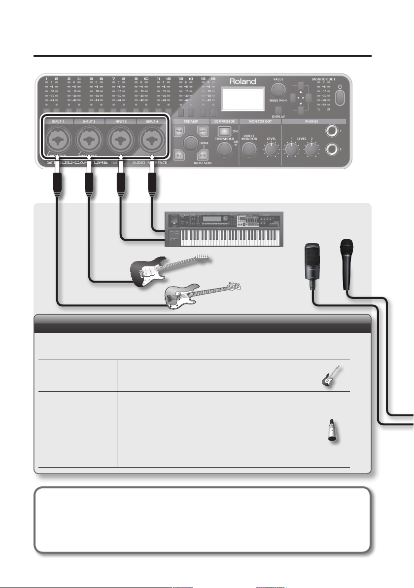
INPUT 1–12 jacks
These are analog audio input jacks equipped with mic preamps. Either balanced or unbalanced sources can be
connected.
Guitar
Bass
Condenser microphone
Dynamic microphone
Howling could be produced depending on the location of microphones relative to speakers. This can be
remedied by:
1. Changing the orientation of the microphone(s).
2. Relocating microphone(s) at a greater distance from speakers.
3. Lowering volume levels.
Connect to either INPUT 1 or 2, and turn Hi-Z on (p. 20).
Connect using a balanced (XLR) plug and turn on the [48V] button
(p. 20).
(Phantom power is not supplied to phone plugs.)
Turn o the [48V] button (p. 20) and connect using a balanced (XLR)
plug.
* The [48V] button must be turned o.
* You must use an XLR plug when connecting a mic.
8
Page 9
Rear Panel
3: COLD
3: COLD
Panel Descriptions
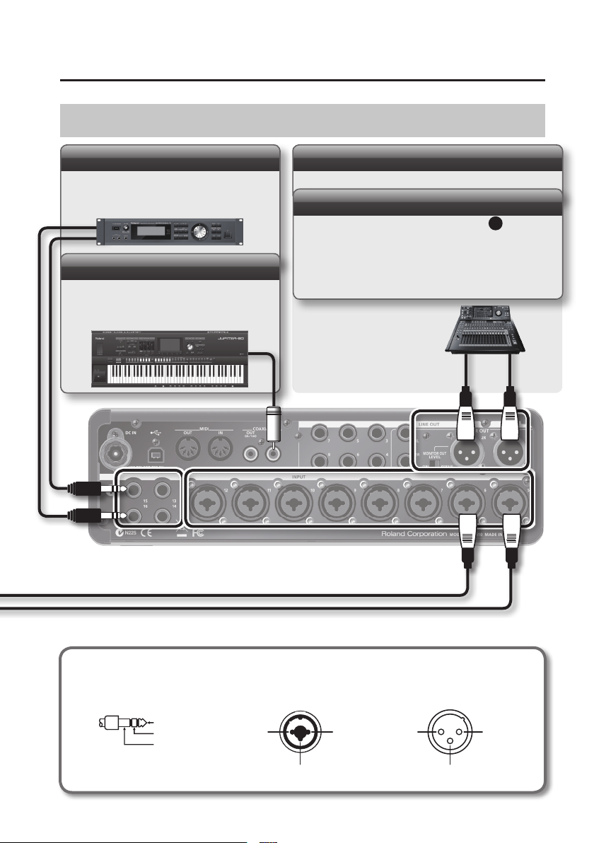
INPUT 13–16 jacks
These are analog audio input jacks. Either balanced or unbalanced sources can be connected.
COAXIAL IN (15/16) jack
Here you can connect a device that is able to
transmit digital audio signals. Alternatively, you
can connect an additional STUDIO-CAPTURE unit
(p. 46).
MONITOR OUT 1L, 2R jacks
Connect a mixer or other device here.
[MONITOR OUT LEVEL] switch
If this is “ON,” the [MONITOR OUT LEVEL] knob 7 will be
enabled.
If this is set to “BYPASS,” the audio signal unaected by the
[MONITOR OUT LEVEL] knob will be output.
For details, refer to the separate “Block Diagram” leaet.
This instrument is equipped with balanced (XLR/TRS) type jacks. Wiring diagrams for these jacks are shown
below. Make connections after rst checking the wiring diagrams of other equipment you intend to connect.
INPUT 1–12 jacks MONITOR OUT 1L, 2R jacks
TIP: HOT
RING: COLD
SLEEVE: GND
1: GND2: HOT
1: GND 2: HOT
9
Page 10
Panel Descriptions
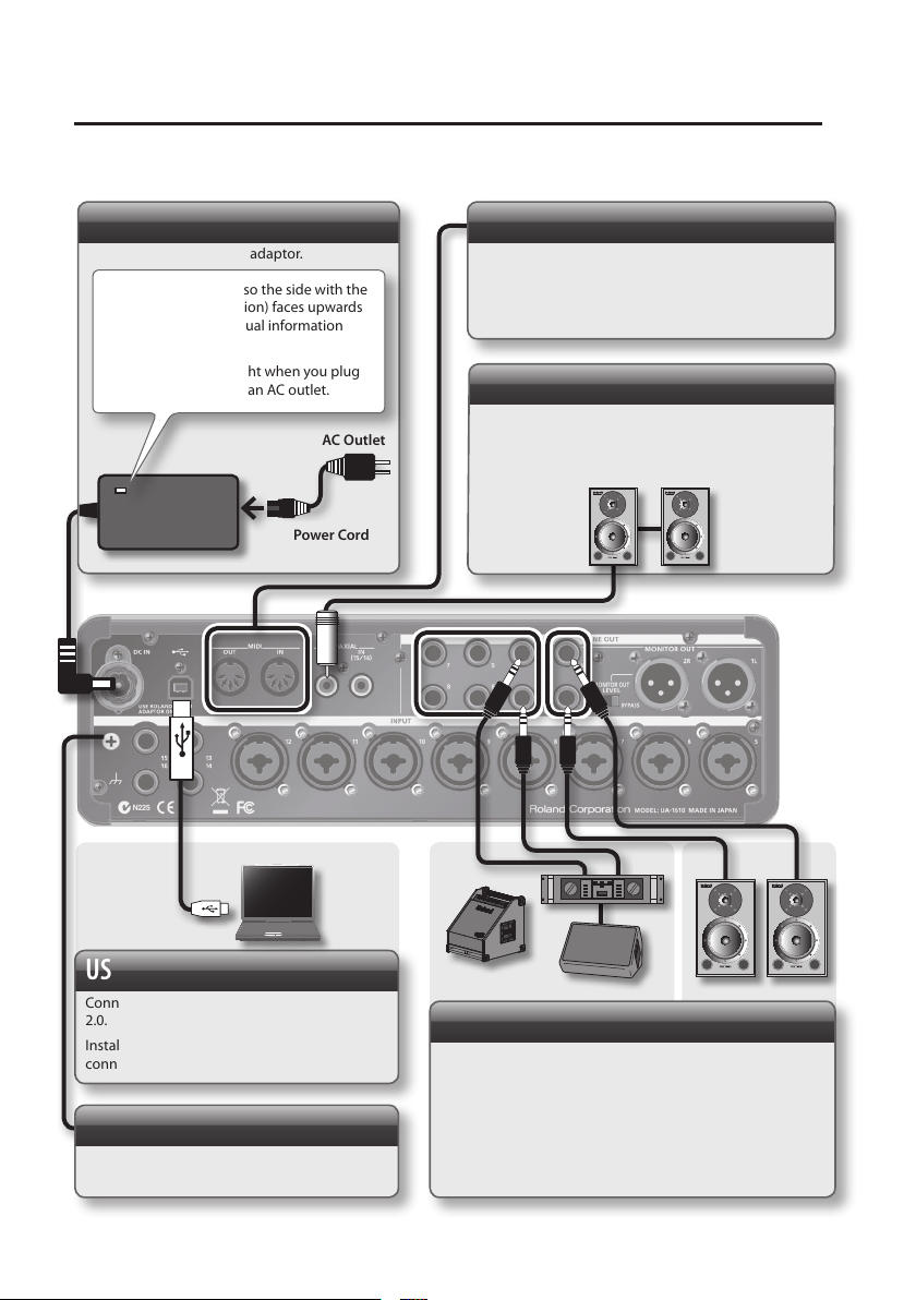
DC IN jack
Connect the included AC adaptor.
Place the AC adaptor so the side with the
indicator (see illustration) faces upwards
and the side with textual information
faces downwards.
* The indicator will light when you plug
the AC adaptor into an AC outlet.
Power Cord
AC Outlet
MIDI IN, OUT connectors
Connect the MIDI OUT connector to an external MIDI
sound module, etc.
Connect the MIDI IN connector to a MIDI keyboard or
MIDI controller.
COAXIAL OUT (9/10) jack
Connect a device that is able to receive digital audio
signals, such as a speaker equipped with digital
input. Alternatively, you can connect an additional
STUDIO-CAPTURE unit (p. 46).
USB port
Connect this to a computer that supports USB
2.0.
Install the USB driver before you make this
connection (p. 11).
Ground terminal
Refer to “Grounding” (p. 76).
10
LINE OUT 1L, 2R, 3–8 jacks
Connect these to devices that are able to receive analog
audio signals, such as amplied speakers.
MONITOR OUT will be output to the LINE OUT 1L and 2R
jacks.
If you’re capturing a band performance and want a dierent
monitor balance for each performer, connect monitor
speakers to the LINE OUT 3–8 jacks as well (p. 45).
Page 11

USB Driver Installation
A USB driver is software installed on your computer that handles data sent between your
computer’s software and the STUDIO-CAPTURE.
In order to use the STUDIO-CAPTURE with a computer, the USB driver must be installed.
NOTE
Do not connect the STUDIO-CAPTURE to the computer until you are directed to do so.
MEMO
Refer to the Roland website for the latest USB drivers and information about compatibility with
the latest operating system versions.
http://www.roland.com/support/
Install the USB Driver (Windows)
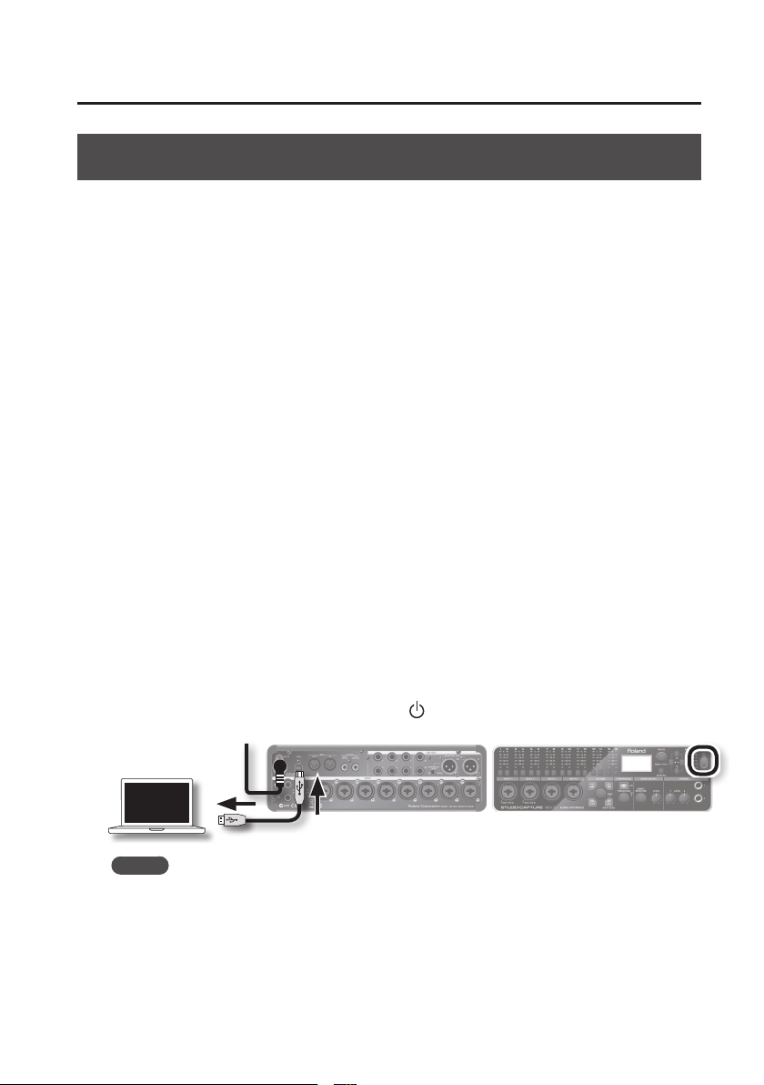
1. Connect the AC adaptor (p. 10).
2. Start up the computer without the STUDIO-CAPTURE connected.
Exit all applications that are running.
Windows 8
Switch to the “Desktop.”
3. Insert the included “STUDIO-CAPTURE Driver CD-ROM” into the DVD-ROM drive.
4. Double-click the [Setup] icon in the [WinDriver] folder on the CD-ROM.
The installer starts.
5. Follow the instructions on the screen and install the software.
When a conrmation screen regarding user account control appears, click the [Yes] button
5-1.
or [Continue] button.
5-2. When “The STUDIO-CAPTURE Driver will be installed on your computer.” appears, click the
[Next] button.
5-3. Click the [Next] button again.
MEMO
• If a dialog box regarding Windows security appears, click the [Install] button.
• If the “Software Install” dialog box appears, click the [Continue] button.
11
Page 12
USB Driver Installation
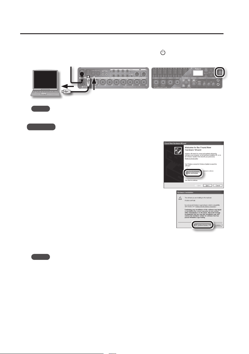
6. When “Ready to install the driver.” appears, connect the STUDIO-CAPTURE to the
computer using the USB cable, and then hold down the [ ] (power) button for
several seconds to turn on the power.
MEMO
If a message appears, follow the instructions on the screen.
Windows XP
If using Windows XP, follow the instructions on the screen and continue the installation.
6-1. If a dialog box that asks whether you want to connect to
Windows Update appears, select the [No, not this time]
button and click the [Next] button.
6-2. Select the [Install the software automatically
(Recommended)] button and click the [Next] button.
6-3. If the “Hardware Installation” dialog box appears, click the
[Continue Anyway] button.
6-4. When “Completing the Found New Hardware Wizard” appears,
click the [Finish] button.
7. When “Installation has been completed.” appears, click the
[Close] button.
The installer exits.
MEMO
If the “Change System Settings” dialog box appears, click the [Yes] button. Windows restarts.
12
Page 13
USB Driver Installation
Install the USB Driver (Mac OS X)
1. Connect the AC adaptor (p. 10).
2. Start up the computer without the STUDIO-CAPTURE connected.
Exit all applications that are running.
3. Insert the included “STUDIO-CAPTURE Driver CD-ROM” into the DVD-ROM drive.
4. Double-click the [StudioCapture_USBDriver] icon in the [MacDriver] folder on the
CD-ROM.
The installer starts.
If a dialog box requesting a password appears during installation, enter a computer
administrator’s user name and password and click the [Install Software] button or [OK] button.
5. Follow the instructions on the screen and install the software.
When “Welcome to the STUDIO-CAPTURE Driver installer” appears, click the [Continue]
5-1.
button.
5-2. If the screen for selecting the installation destination appears, select the startup disk and
click the [Continue] button.
5-3. When the installation type appears, click the [Install] button or [Upgrade] button.
5-4. Click the [Continue Installation] button in the next screen.
5-5. When installation has nished, click the [Restart] button.
6. Once your computer has started, use a USB cable to connect the STUDIO-CAPTURE
to the computer, and then hold down the [
turn on the power.
MEMO
Refer to “Mac OS X MIDI Settings” (p. 56) if you intend to use MIDI.
] (power) button for several seconds to
13
Page 14

USB Driver Installation
Conrm that Sound Can Be Heard
Congure the computer so that audio played from a program that uses the computer’s audio
features, such as Music (Windows 8 app), Windows Media Player or iTunes, can be heard.
1. Connect the headphones or amplied speakers (p. 7, p. 10).
* To prevent malfunction and equipment failure, always turn down the volume, and turn o all
the units (except the computer) before making any connections.
2. Use the following procedure to select the “STUDIO-CAPTURE” as the system audio
output device.
Windows 8/Windows 7/Windows Vista
2-1. Open the “Control Panel,” click the [Hardware and Sound] icon, and then click the [Sound]
icon. If you have selected Icon view or Classic view, double-click the [Sound] icon.
2-2. Click the [Playback] tab, select the STUDIO-CAPTURE’s [1–2], and then click the
[Set Default] button.
2-3. Click the [OK] button.
Windows XP
2-1. Open the “Control Panel,” click the [Sounds, Speech, and Audio Devices] icon, and then
double-click the [Sounds and Audio Devices] icon. If you have selected Classic view,
double-click the [Sounds and Audio Devices] icon.
2-2. Click the [Audio] tab and select [1–2 (STUDIO-CAPTURE)] in the [Sound playback] area.
When connecting the external MIDI sound module, select [STUDIO-CAPTURE] in the [MIDI
music playback] area.
2-3. Click the [OK] button.
Mac OS X
2-1. Open “System Preferences” and click the [Sound] icon.
2-2. Click the [Output] tab and select [STUDIO-CAPTURE].
2-3. When you have nished making these settings, quit “System Preferences.”
3. Open the folder named [Sample] on the included CD-ROM, and copy the le “TTears
(.mp3)” to the desktop.
4. Double-click the le “TTears (.mp3)” that you copied to the desktop.
Music (Windows 8 app), Windows Media Player or iTunes starts.
Click the playback button to play the sample le.
14
Page 15

USB Driver Installation
MEMO
• The software that starts and is used to play the sample le may vary depending on your
computing environment. If dierent software starts, play the sample le as described in the
owner’s manual for the software you are using.
• If you cannot select “STUDIO-CAPTURE” in step 2-2, refer to “Using the STUDIO-CAPTURE“ (p. 60).
• If the STUDIO-CAPTURE is selected as the output device, the computer’s audio alerts will be
played using the STUDIO-CAPTURE; they will not be heard from the computer’s speakers.
To open the Control Panel
Windows 8
1. On the Start screen, click the Desktop.
2. Move the mouse pointer to the upper right or lower right corner of the screen
to display the charms.
* On touch-enabled PCs, swipe from the right side of the screen to display the charms.
3. Click [Settings] and display the “Settings charms.”
4. In “Settings charms,” click [Control Panel] to open the “Control Panel.”
15
Page 16

Basic Operation
Connecting Equipment
Connect guitars and mics to the INPUT jacks, and amplied speakers to the LINE OUT 1L and 2R
jacks. Headphones can be connected to the PHONES 1 jack and PHONE 2 jack (p. 6–p. 10).
Turning the Power On/O
* Before you proceed, you must install the USB driver on your computer (p. 11).
* Once everything is properly connected (p. 6–p. 10), be sure to follow the procedure below to turn
on their power. If you turn on equipment in the wrong order, you risk causing malfunction or
equipment failure.
Turning the Power On
1. Turn the [MONITOR OUT LEVEL] knob and [PHONES LEVEL 1] [PHONES LEVEL 2]
knobs all the way to the left.
2. Connect the STUDIO-CAPTURE to the computer using the USB cable.
3. Switch on the power to any external equipment connected to the input jacks.
4. Press and hold the STUDIO-CAPTURE’s [ ] (Power) button for several seconds, and
then release it.
* This unit is equipped with a protection circuit. A brief interval (a few seconds) after turning the
unit on is required before it will operate normally.
* Before turning the unit on/o, always be sure to turn the volume down. Even with the volume
turned down, you might hear some sound when switching the unit on/o. However, this is
normal and does not indicate a malfunction.
5. Switch on the power to your amp or powered monitor speakers.
6. During playback, adjust the volume by turning the [MONITOR OUT LEVEL] knob and
[PHONES LEVEL 1] [PHONES LEVEL 2] knobs toward the right.
16
Page 17
Basic Operation
Turning the Power O
Before you turn o the power, make sure to do the following.
• Turn the [MONITOR OUT LEVEL] knob and [PHONES LEVEL 1] [PHONES LEVEL 2] knobs all the
way to the left
• Minimize the volume of all connected equipment
1. Switch o the power to your amp or powered monitor speakers.
2. Press and hold the STUDIO-CAPTURE’s [ ] (Power) button for several seconds, and
then release it.
The next time you turn the power on, the unit will start up with the settings that were in eect
when it was powered o.
3. Switch o power to the connected equipment.
Making the Power Automatically Turn O After a Time
(Auto O)
When not connected to a computer, the STUDIO-CAPTURE will automatically be switched o four
hours after you stop playing or operating it (if the factory settings have been unmodied). If you
don’t want the unit to turn o automatically, change the “AUTO-OFF” setting to “OFF” as described
below.
NOTE
• Any settings that you are in the process of editing will be lost when the power is turned o. If
you have any settings that you want to keep, you should save them beforehand.
• To restore power, turn the power on again.
MEMO
Auto O will not function if the STUDIO-CAPTURE is connected to your computer, or if a
microphone/instrument is connected.
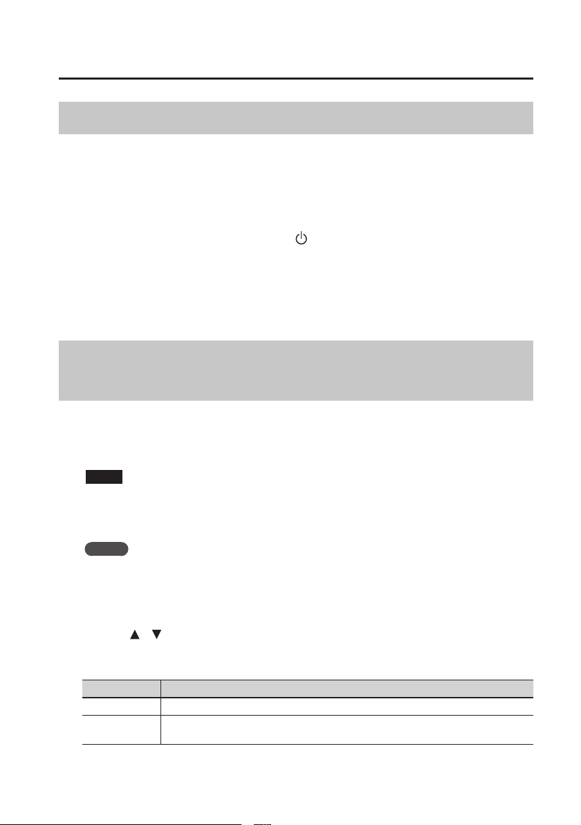
1. Press the [VALUE] knob ([MENU] button) to access the SYSTEM screen.
2. Use the [ ] [ ] buttons to choose “AUTO-OFF.”
3. Turn the [VALUE] knob to choose “4HOURS” or “OFF.”
Value Explanation
OFF The power will not turn o automatically.
4HOURS
(default)
When not connected to a computer/microphone/instrument, the STUDIO-CAPTURE will
automatically be switched o four hours after you stop operating it.
4. Press the [DISPLAY] button to return to the main screen (p. 18).
17
Page 18
Basic Operation
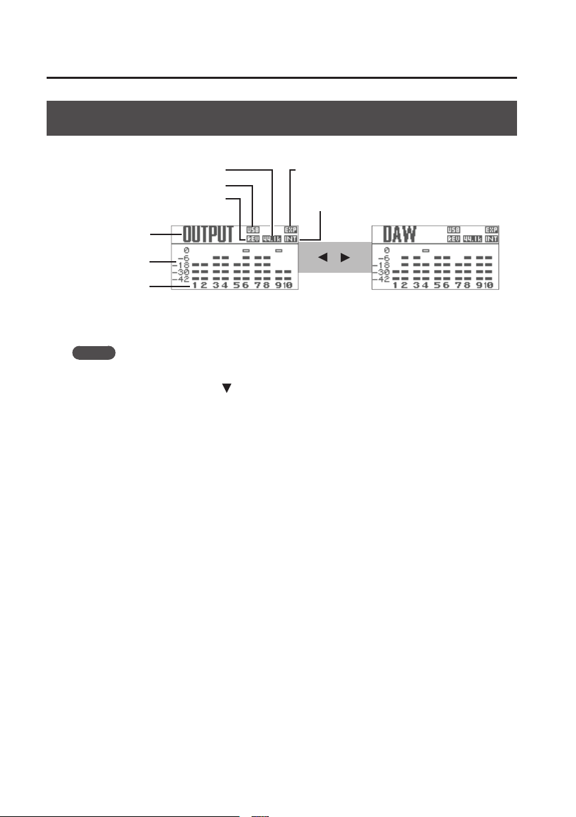
Checking the Levels
The output levels are shown in the main screen.
Sampling rate
Indicate when connected via USB
Indicate if reverb is being applied
Name of the level meters
currently shown
Level meter
Channel number
Output level from the STUDIO-CAPTURE’s
LINE OUT jacks
MEMO
• If you press the [DISPLAY] button from other screens, you’ll switch to this main screen.
• In the main screen, press the [
] button to access the MIX A screen (p. 24).
Indicate if two STUDIO-CAPTURE units are connected
Sync indicator
Internal clock (INT), External clock (EXT )
[ ]
[ ]
Output level from the computer
18
Page 19
Basic Operation
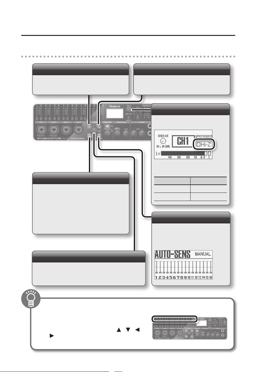
Adjusting the Audio Signals
Adjusting the Mic Preamp and Compressor
Each INPUT 1–12 jack has its own mic preamp and compressor which can be adjusted
independently.
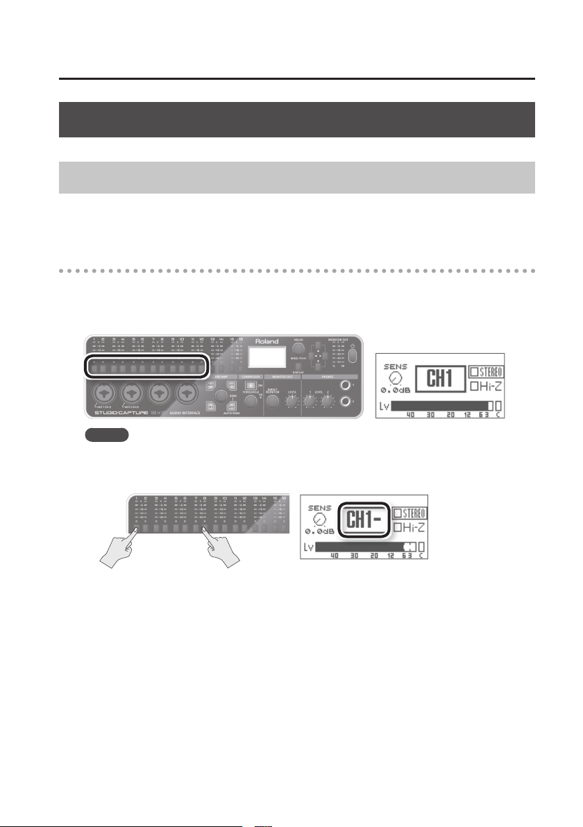
1. Select the channel that you want to set
Press the input channel button (1–12) of the channel that you want to set; the input channel
indicator will light. The display will show the preamp screen.
You can press the [DISPLAY] button to return to the main screen.
MEMO
To select multiple channels (Range Select function), simultaneously press the rst and last
input channel buttons.
The display will show the rst channel number and “-.”
In this example, channels 1–8 are selected.
19
Page 20
Basic Operation
2. Adjusting the mic preamp
Phase setting
If you want to invert the phase of the audio input
signal, press the [PHASE] button so it’s lit.
Phantom power on/o
To supply phantom power, press the [48V] button
so it’s lit.
Turn this on if you’re using a condenser mic.
* Leave the [48V] button o if you’re connecting
a device that does not support phantom power.
Supplying phantom power to such a device will
cause malfunction.
Low-cut on/o
To apply the low-cut lter, press the [LoCUT]
button so it’s lit.
The cuto frequency is 75 Hz.
Hi-Z on/o
* This function is for the INPUT 1 and
2 jacks.
Turn the [VALUE] knob to switch the
input impedance.
Device Hi-Z
Guitar/Bass On
Mic, etc. O
Auto-sens
If you use AUTO-SENS, the input level
will be automatically set according to
the highest level of the audio input
signal (p. 21).
Adjusting the sensitivity
Turn the [SENS] knob to adjust the input gain so that the
peak indicator (0; red LED) of the input level meter does
not blink.
To clear the lit peak indicators
Turn the [VALUE] knob or
press any of the following buttons: input
channel buttons, [MENU], cursor[ ] [ ] [ ]
[ ], or [DISPLAY].
20
Page 21
Basic Operation
Using AUTO-SENS
1. Press the [AUTO-SENS] button; it will blink.
2. While the button is blinking, perform the loudest portion of the song.
If you decide to cancel, press the [DISPLAY] button.
3. Stop performing.
There is no input for approximately four seconds, then the [AUTO-SENS] button will
change from rapid blinking to being unlit, and you’ll exit this setting.
MEMO
If you want to change the maximum recording level setting used by AUTO-SENS,
or if you want to manually exit AUTO-SENS, you can make these changes in the
SYSTEM screen (p. 39).
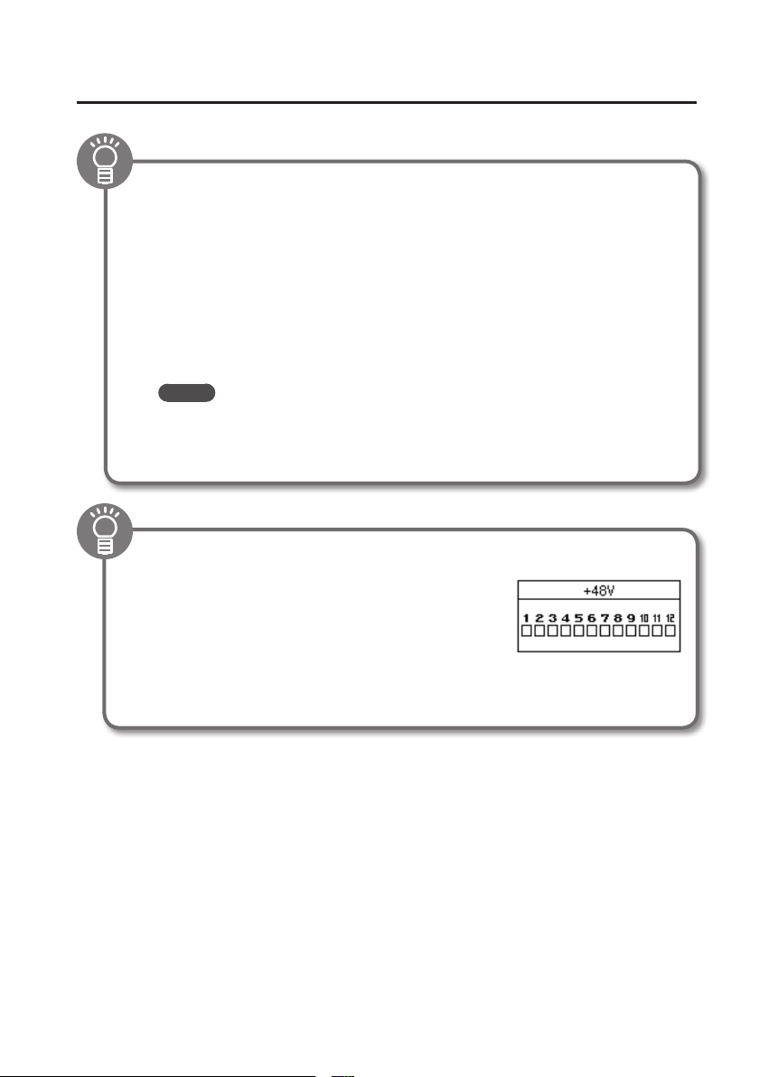
Checking the phantom power on/o status for each jack
If you press and hold the [48V] button, you’ll see the
phantom power on/o status for each of the INPUT 1–12
jacks.
To switch phantom power on/o, continue holding the
[48V] button and press the corresponding input channel
button.
* This also works for the [PHASE], [LoCUT], and [COMPRESSOR] buttons.
21
Page 22
Basic Operation
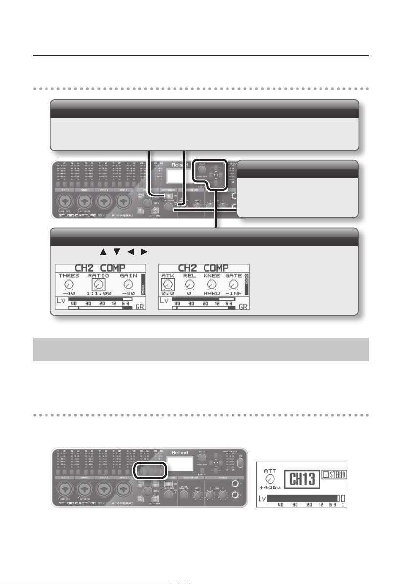
3. Adjusting the compressor
Turning the compressor on/o
If you want to compress the high levels and boost the low levels to make the volume consistent and
avoid distortion, press the [COMPRESSOR] button so it’s lit.
When the compressor is applied, the GR indicator will light.
Adjusting threshold
Turn the [THRESHOLD] knob to adjust
the THRESHOLD setting.
Adjusting other parameters (p. 31)
Use the cursor [ ] [ ] [ ] [ ] buttons and the [VALUE] knob to adjust the parameters.
Adjusting the Attenuator
An attenuator is provided for each of the INPUT 13–16 jacks, allowing you to boost or cut each
audio signal independently.
1. Select the channel that you want to set
Press the input channel button (13–16) of the channel that you want to set; the input channel
indicator will light. The display will show the attenuator screen.
22
Page 23
Basic Operation
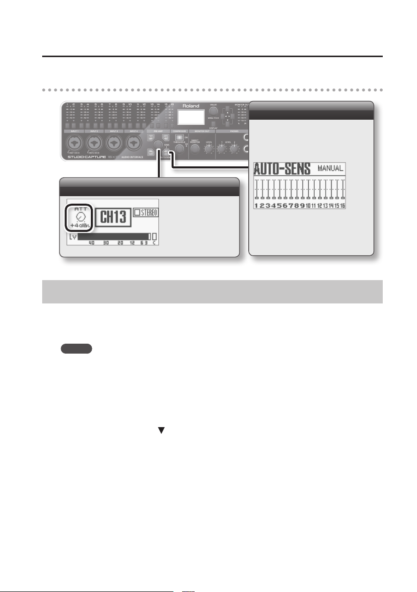
2. Adjusting the input channel
Auto-sens
If you use AUTO-SENS, the input level
will be automatically set according to
the highest level of the audio input
signal (p. 21).
Adjusting the nominal input rating
Turn the [SENS] knob
to adjust the input
attenuator so that the
peak indicator (0; red
LED) of the input level
meter does not blink.
Adjusting the Direct Monitor Settings
On the STUDIO-CAPTURE, the audio signals being input via the INPUT jacks can be output for
monitoring without sending them through your computer (direct monitoring). A stereo mixer is
provided for you to specify the balance by adjusting the level and pan individually.
MEMO
You can also use the STUDIO-CAPTURE Control Panel (p. 27) to do the following things.
• You can adjust the balance of not only the audio signals received at the INPUT jacks but also
the balance of sound played back from your computer.
• There are four mixers, allowing you to create four monitor mixes, each with their own balance,
as described in ”Outputting to Four Monitor Systems” (p. 45)
In the main screen, press the [
] button to access the MIX A screen.
23
Page 24
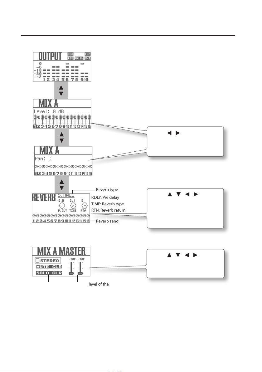
Basic Operation
Main screen
[
[ ]
]
[
[ ]
[
[ ]
]
]
Reverb type
P.DLY: Pre delay
TIME: Reverb type
RTN: Reverb return
Reverb send
Use the [ ] [ ] cursor buttons to
switch input channels, and use the
[VALUE] knob to change the value.
Use the [ ] [ ] [ ] [ ] buttons
to move the cursor, and use the
VALUE knob to change the value.
For more about reverb, refer to
”Reverb” (p. 35).
You can also turn the [DIRECT MONITOR] knob to adjust the overall level of all direct monitoring.
Use the [ ] [ ] [ ] [ ] buttons to
move the cursor, and use the VALUE
knob to change the value.
Stereo link
Mute clear
Solo clear
Output level of the
input mixer
24
Page 25

Basic Operation
Setting Input and Output Device
Precautions concerning the use of DAW software
• Connect the STUDIO-CAPTURE to the computer before starting the DAW software.
• Do not disconnect the STUDIO-CAPTURE from the computer while the DAW software is
running. After exiting the DAW software, disconnect the STUDIO-CAPTURE.
• Select the STUDIO-CAPTURE for the DAW software’s audio device setting.
Congure the settings necessary to use the DAW software to play audio and MIDI, and to record
audio.
Select the STUDIO-CAPTURE as the audio and MIDI input device, and as the output device. For
details about settings, refer to the documentation for your software.
Audio output device
Device name WDM, MME/KS ASIO
OUT 1–2
OUT 1–2 (2)
OUT 3–4
OUT 3–4 (4)
OUT 5–6
OUT 5–6 (6)
OUT 7–8
OUT 7–8 (8)
9–10
9–10 (10)
STUDIOCAPTURE
1–2 (STUDIO-CAPTURE)
3–4 (STUDIO-CAPTURE)
5–6 (STUDIO-CAPTURE)
7–8 (STUDIO-CAPTURE)
9–10 (STUDIO-CAPTURE)
44.1, 48, 96
kHz
192 kHz
—
—
—
25
Page 26

Basic Operation
Audio input device
Device name WDM ASIO
IN 1–2
IN 1–2 (2)
IN 3–4
IN 3–4 (4)
IN 5–6
IN 5–6 (6)
IN 7–8
IN 7–8 (8)
IN 9–10
IN 9–10 (10)
IN 11–12
IN 11–12 (12)
IN 13–14
IN 13–14 (14)
IN 15–16
IN 15–16 (16)
MONITOR
MONITOR (R)
STUDIOCAPTURE
1–2 (STUDIO-CAPTURE)
3–4 (STUDIO-CAPTURE)
5–6 (STUDIO-CAPTURE)
7–8 (STUDIO-CAPTURE)
9–10 (STUDIO-CAPTURE)
11–12 (STUDIO-CAPTURE)
13–14 (STUDIO-CAPTURE)
15–16 (STUDIO-CAPTURE)
MONITOR (STUDIO-CAPTURE)
MIDI output device/MIDI input device
44.1, 48, 96
kHz
192 kHz
—
—
—
—
—
Device name MIDI port name
STUDIO-CAPTURE STUDIO-CAPTURE
26
Page 27

Control Panel: MONITOR
p. 32
p. 30
Using the STUDIO-CAPTURE Control Panel
Internal Blocks of the STUDIO-CAPTURE
In addition to its audio interface, the STUDIO-CAPTURE internally contains 12 preamps, 4
attenuators, 4 monitor mixers, and a patch bay.
These preamps, attenuators, monitor mixers, and patch bay can be controlled from a special
control panel installed on your computer (p. 29).
The STUDIO-CAPTURE Control Panel is automatically installed when you install the USB driver.
Preamp
p. 32
Attenuator
[48V] SW
controlled by
software
individually
INPUT 1
INPUT 2
INPUT 3
INPUT 4
INPUT 5
INPUT 6
INPUT 7
INPUT 8
INPUT 9
INPUT 10
INPUT 11
INPUT 12
INPUT 13
INPUT 14
INPUT 15
INPUT 16
COAXIAL IN
(15/16)
Monitor mixer A, B, C, D
p. 30
48V
HiZ/
75Hz
PHASE
SENS
LoZ
/
HiZ/
LoZ
ATT
ATT
ATT
ATT
COMP
HPF
75Hz
PHASE
COMP
SENS
HPF
75Hz
PHASE
SENS
COMP
HPF
75Hz
SENS
PHASE
COMP
HPF
75Hz
PHASE
COMP
SENS
HPF
75Hz
PHASE
COMP
SENS
HPF
75Hz
PHASE
SENS
COMP
HPF
75Hz
PHASE
SENS
COMP
HPF
75Hz
PHASE
COMP
SENS
HPF
75Hz
PHASE
SENS
COMP
HPF
75Hz
PHASE
COMP
SENS
HPF
75Hz
PHASE
SENS
COMP
HPF
WAVE IN
To USB From USB
1/2
9/107/85/63/4 MON 1/2 9/107/85/63/4
15/1613/1411/12
WAVE OUT
MONITOR A–D
8
MONITOR A
DIRECT MONITOR A
Reverb
(DIRECT MONITOR A
Only)
DAW MONITOR A
MONITOR OUT level meter
PATCHBAY
p. 32
[DIRECT MONITOR] knob
PHONES 1
[PHONES 1 LEVEL] knob
PHONES 2
[PHONES 2 LEVEL] knob
MONITOR OUT 1L
/ LINE OUT 1L
MONITOR OUT 2R
/ LINE OUT 2R
[MONITOR OUT LEVEL] switch
MONITOR OUT 1L
/ LINE OUT 1L
MONITOR OUT 2R
/ LINE OUT 2R
[MONITOR OUT LEVEL] knob
LINE OUT 3
LINE OUT 4
LINE OUT 5
LINE OUT 6
LINE OUT 7
LINE OUT 8
COAXIAL OUT
(9–10)
Control Panel: PATCHBAY
MONITOR
OUT
p. 37
Patch bay
p. 32
p. 37
For details on the block diagram, refer to the separate “Block Diagram” leaet.
27
Page 28

Using the STUDIO-CAPTURE Control Panel
MEMO
Some of the settings, such as those for the preamps, can be controlled by the knobs and
buttons of the STUDIO-CAPTURE itself (p. 19).
Preamps
You can set the input sensitivity for each of the INPUT 1–12 jacks. You can also set the input
sensitivity automatically.
Phantom power is also supported. Since it can be switched on/o individually for each channel,
you are free to use mixed setups that contain both dynamic mics and condenser mics.
In addition, the various parameters such as the low-cut and phase of each channel can be digitally
controlled.
For details, refer to ”Preamp Control Screen” (p. 30).
Attenuators
Each of the INPUT 13–16 jacks lets you attenuate the incoming audio signal, allowing you to
adjust the input level. Attenuator settings can also be made automatically.
For details, refer to ”Attenuator Screen” (p. 32).
Monitor mixers A, B, C, D
This allows the input signals to be directly output for monitoring without being routed through
the computer. You can adjust the balance among these signals and the playback from the
computer.
The direct mixer is a queue mixer that provides individual adjustment of volume and pan for each
input and each playback channel from the computer.
You can control the four mixers independently.
For details, refer to ”Preamp Control Screen” (p. 30).
Patch bay
This allows you to assign the output destinations of the four monitor mixers and the output
destinations of the playback channels from the computer.
For details, refer to “Patch Bay” (p. 37).
28
Page 29

Using the STUDIO-CAPTURE Control Panel
Starting the STUDIO-CAPTURE Control Panel
Access the STUDIO-CAPTURE Control Panel as follows.
Windows 8
Display the “Start” screen and click [STUDIO-CAPTURE].
* On the “Start” screen, if [STUDIO-CAPTURE] does not exist, then open the “Control Panel,”
switch “View by:” to the icon view (Large icons or Small icons).
Windows 7/Windows Vista/Windows XP
Click the Windows [Start], then successively click [Roland], [STUDIO-CAPTURE Driver], and
[STUDIO-CAPTURE].
* If you don’t see the STUDIO-CAPTURE icon, open the “Control Panel” and switch to Icon view
(Windows 7) or Classic view (Windows Vista/Windows XP).
Mac OS X
Open the “Applications” folder, and double-click the [STUDIO-CAPTURE Control Panel] icon.
MEMO
For more about using the STUDIO-CAPTURE Control Panel, you can also choose “View
README” from the STUDIO-CAPTURE Control Panel.
Windows version From the “Driver” menu, choose “Show README”
Mac OS X version From the “STUDIO-CAPTURE Control Panel” menu, choose “Show README”
29
Page 30

Using the STUDIO-CAPTURE Control Panel
Controlling the Preamps and Mixers
Preamp Control Screen
Switch to the monitor mixer control
screen (p. 32).
Preamp
You can control these settings individually for each input jack.
If this is on, sensitivity and compressor settings will be linked
in stereo (refer to the column on p. 33).
Supplies phantom power (
this on if you’re using a device that
requires phantom power, such as a
condenser mic.
p. 20
). Turn
Show the attenuator screen
(p. 32).
Preamp control
Refer to “Device
panel” (p. 36).
Click this to open the AUTO-SENS screen (p. 20).
Select the channel for which you want to execute
Auto-Sens, input an audio signal, and nally click
[FINISH].
Enables the low cut lter for the
input (p. 20).
The cuto frequency is 75 Hz.
Adjusts the input signal’s gain over a
range of 0–58 dB, in steps of 0.5 dB.
30
Choose the Hi-Z (ON) setting if you’ve
connected a guitar, and choose the Lo-Z (OFF)
setting if you’ve connected any other device
(p. 20).
Inverts the phase of the input signal (p. 20).
Shows the level of the signal that is input to the
preamp.
Page 31

Compressor
Disables the compressor.
Using the STUDIO-CAPTURE Control Panel
The OUT meter shows the status of
the signal that is output from the
compressor.
The GR meter shows the amount
of gain reduction applied by the
compressor.
Select a compressor preset.
Species the signal level at which
the compressor begins operating.
(dB)
Make detailed compressor settings.
Compressor presets
You can save your favorite settings as user presets, and load them later when you need
them.
Mutes signals below the specied
level. (dB)
Species the compression ratio
at which the audio signal is to be
compressed.
Adjusts the output level of the compressor. (dB)
Adjusts whether the compressor will start being
applied abruptly when the threshold level is
exceeded, or will change smoothly and gradually
around the threshold level.
Species the time from when the input level falls
below the threshold level until the compressor
stops operating. (msec)
Species the time from when the input level
exceeds the threshold until the compressor begins
to operate. (msec)
To save
To load
Click [PRESET], then [Store...], then the save-destination preset number (U00–U15),
and enter a preset name of up to 16 characters.
Click [PRESET], then [User Preset], then the preset number that you want to load
(U00–U15).
31
Page 32

Using the STUDIO-CAPTURE Control Panel
Attenuator Screen
Each of the INPUT 13–16 jacks lets you attenuate the incoming audio signal, allowing you to
adjust the input level
If this is on, attenuator settings will be
linked in stereo.
Adjust the attenuation, and
switch the nominal input levels
as appropriate for the connected
devices.
Monitor Mixer Control Screen
If this is on, the four mixers A–D can be controlled independently. Tabs B, C, and D will appear below in
addition to the MONITOR A tab.
In addition, the patch bay will switch to the settings for when the [MULTIPLE-MONITOR] button (p. 37) is
pressed in the PATCHBAY dialog box.
Direct monitor DAW monitor
MEMO
• With the factory settings, only monitor mixer A is shown. If you want to control the four mixers,
click the [MULTIPLE-MONITOR] button.
• If the unit is operating at the 192 kHz sample rate, only monitor mixer A is available.
Switches to the
preamp control
screen (p. 30).
Master
Device panel
32
Page 33

Using the STUDIO-CAPTURE Control Panel
Direct monitors A–D
Here you can control the monitor level and balance of the audio data being input via INPUT 1–16
jacks.
If this is on, settings other than
PAN will be linked in stereo (refer
to the column on this page).
Switches muting on/o.
Switches solo on/o (refer to p. 35’s
column).
Shows the level of the signal that
is input to the mixer.
Adjusts the send level to the reverb
unit (direct monitor A only).
For more about the reverb unit on/
o and type settings, refer to “Reverb”
(p. 35).
Species the panning of the sound.
Adjusts the monitor level of the audio
input signal.
MEMO
Direct monitor “A” can be controlled from the STUDIO-CAPTURE unit itself (p. 23).
Changing what happens when the [STEREO] button is turned on
You can specify whether the [STEREO] button of the same channels in the preamp
control screen and the monitor mixer control screen (p. 32) will be linked when you click
the [STEREO] button.
In the STUDIO-CAPTURE Control Panel, click the “Device” menu, then click [Device
Settings] and make this setting.
Value Explanation
INDIV.
PAIRED
Stereo link can be turned on/o individually for the preamp and
the monitor mixer.
Stereo link will turn on/o simultaneously for the preamp and the
monitor mixer.
33
Page 34

Using the STUDIO-CAPTURE Control Panel
DAW monitor A–D
Here you can control the balance of the ve stereo channels of audio data sent from the computer,
and send it to the headphones or the monitoring section.
You can control the four output mixers independently.
If this is on, settings other than
PAN will be linked in stereo.
Switches mute on/o.
Switches solo on/o (refer to the
column on p. 35).
Shows the level of the signal that
is output from the compressor.
Species the panning of the sound.
Adjusts the monitor level of the audio
signal from the computer.
Master A–D
Here you can control the master output levels of the direct monitor and the DAW monitor.
If this setting is on, the master
volume of the director monitor
and DAW monitor will be linked.
Display the reverb dialog (direct
monitor A only).
Adjusts the reverb type and delay
time, etc. (p. 35).
Indicates the output destination for
each monitor mixer.
* Use the patch bay (p. 37) to specify the
output destination.
Adjusts the return level to the reverb
unit (direct monitor A only).
If this is on, the master output levels
of the left and right channels will be
linked.
34
Adjust the master output levels for
direct monitor and DAW monitor,
respectively.
Page 35

Using the STUDIO-CAPTURE Control Panel
Reverb
You can apply reverb to the audio signal of the direct monitor in the monitor mixer A.
Setting Value Explanation
OFF No reverb will be applied.
ECHO Echo will be applied.
ROOM Reverb that simulates the reverberation of a room.
TYPE
PREDELAY
TIME 0.1–5.0 s Adjusts the time over which the reverberation decays to silence.
MEMO
• You can adjust the PRE-DELAY and TIME parameters for each TYPE.
• The reverb can also be controlled from the STUDIO-CAPTURE itself (p. 24).
• Reverb is not available when operating at a sampling rate of 192 kHz.
SMALL HALL
LARGE HALL
PLATE
0, 0.1, 0.2, 0.4, 0.8,
1.6, 3.2, 6.4, 10,
20, 40, 80, 160 ms
Reverb that simulates the reverberation of a hall; produces a more spacious
reverberation than ROOM.
Simulates plate reverberation (a reverb unit that uses the vibration of a
metallic plate). Provides a metallic sound with a distinct upper range.
Adjusts the time from when the direct sound is output until the eect sound
is output.
Lengthening the pre-delay will create an eect in which multiple sounds are
heard.
Changing how the [SOLO] button works
You can specify complete muting or a specic level reduction for the channels other
than the soloed channel in the monitor mixer control screen.
In the STUDIO-CAPTURE Control Panel, click the “Device” menu, then click [Device
Settings] and make this setting.
Value Explanation
OFF The channels will be muted.
-6 The level will decrease by -6 dB.
-12 The level will decrease by -12 dB.
-18 The level will decrease by -18 dB.
35
Page 36

Using the STUDIO-CAPTURE Control Panel
Device panel
Here you can view the status of the STUDIO-CAPTURE’s settings.
Selects which unit’s mixer will be shown
when two STUDIO-CAPTURE units are
connected (p. 46).
When you click this button, the display of
the STUDIO-CAPTURE unit itself will be
highlighted.
If you use only one unit, it showed
STUDIO-CAPTURE only.
Indicates/Sets the sampling rate.
Indicates the clock source.
Setting Explanation
INTERNAL
EXTERNAL
The STUDIO-CAPTURE’s internal
clock is used.
The STUDIO-CAPTURE is operating
in synchronization with the digital
signal being input to COAXIAL IN
(15/16) jack.
About the sampling rate
The sampling rate setting of the STUDIO-CAPTURE automatically changes to match
the rate of the audio data that is played, or the rate that your DAW software is set to
when recording.
But you can also change the sampling rate of the STUDIO-CAPTURE manually. Click
[
] of the SAMPLE RATE on the device panel, then select another sampling rate. In
this case, you may also need to change the sampling rate of the DAW software.
* The sampling rate cannot be changed during playback or recording, or when
equipment is connected to the COAXIAL IN (15/16) jack.
* When the sampling rate is switched, a small pop noise may be heard, but this does
not indicate a malfunction.
36
Page 37

Using the STUDIO-CAPTURE Control Panel
Patch Bay
The PATCHBAY dialog box will appear when you choose [Open the Patchbay] from the “Device”
menu.
As appropriate for your needs, you can freely assign the output destinations of the four monitor
mixers and the output destinations of the playback channels from the computer.
* The patch bay is not available when operating at a sampling rate of 192 kHz.
MEMO
The patch bay can also be controlled from the STUDIO-CAPTURE itself (p. 43).
Patch bay
MONITOR A
B
C
D
WAVE OUT 1–2
3–4
5–6
7–8
9–10
OUTPUT 1–2
OUTPUT 3–4
OUTPUT 5–6
OUTPUT 7–8
OUTPUT 9–10 COAXIAL OUT (9/10) jack
For each output jack, choose the source that you want to patch.
LINE OUT 1L, 2R jacks
PHONES 1, 2 jacks
MONITOR OUT 1L, 2R jacks
LINE OUT 3–8 jacks
Restores the default settings.
* This setting is convenient if you’re using the “soft-thru”
function of your DAW software such as SONAR,
instead of using the STUDIO-CAPTURE’s direct monitor
function.
Outputs to four monitor systems.
* The patch bay will have these settings when
you click the [MULTIPLE DIRECT MIXER] button
(p. 32) in the monitor control screen.
The output from the computer will be output
without change.
37
Page 38

Using the STUDIO-CAPTURE Control Panel
Saving or Loading Settings on the Computer
From the STUDIO-CAPTURE Control Panel, you can save the current settings as a le, or load
previously saved settings from a le.
The following settings are saved.
• Preamp (p. 30)
• Compressor (p. 31)
• Attenuator (p. 32)
• Monitor mixer A–D (p. 32)
• Reverb (p. 35)
• Patch bay (p. 37)
* If you’re using two connected STUDIO-CAPTURE units, you can save the settings for each unit
individually. To save settings for both units, select each in the device panel and its settings.
Saving settings
1. From the “Device” menu, choose [Save settings].
2. Specify the le in which the settings are to be saved.
Loading settings
1. From the “Device” menu, choose [Load settings].
2. Specify the le that contains the settings you want to load.
Saving or Loading Compressor Presets on the Computer
You can save 16 user presets (numbers U00–U15) as a le, and load a set of 16
user presets from a le.
Saving user presets as a le
1. In the preamp control screen (p. 30), click [PRESET], then [User Preset], then [Save User
Presets...].
2. Specify a name for the le to be saved.
38
Page 39

Using the STUDIO-CAPTURE Control Panel
Loading user presets from a le
1. In the preamp control screen (p. 30), click [PRESET], then [User Preset], then [Load User
Presets...].
2. Select the le that you want to load.
* When you load user presets from a le, all 16 of the currently stored user presets will be
overwritten.
Changing the AUTO-SENS Settings
You can choose whether AUTO-SENS (p. 30) will be ended automatically or manually. You can also
specify the maximum setting for the recording level. The recording level will be set automatically
according to the maximum volume that was input during the AUTO-SENS setting time.
MEMO
The setting can also be controlled from the STUDIO-CAPTURE itself (p. 43).
1. From the “Device” menu, select [Device settings].
2. From the items in “AUTO-SENS,” select “AUTO” or “MANUAL.”
Value Explanation
AUTO
(default)
MANUAL The AUTO-SENS setting will not nish until you press the [AUTO-SENS] button again.
The AUTO-SENS setting will nish automatically after there has been no input for
approximately four seconds, after the [AUTO-SENS] button was pressed.
3. Using “Margin,” you can change the maximum value of the recording level that is
detected.
Range for Margin: 0–12
Value Explanation
6 (default) Headroom is set at 6 dB. This setting provides a good overall balance.
0
12 Headroom is set at 12 dB. The recording level will be reduced.
The maximum value for the recording level is set at 0 dBFS. Clipping will occur if audio
that exceeds the recording level detected by AUTO-SENS is input.
39
Page 40

Using the STUDIO-CAPTURE Control Panel
Directly Outputting Each Channel’s Input
If you choose the command [Directly Output the Inputs] from the “Device” menu, the input signals
from the INPUT 1–8 jacks will be passed directly to the output jacks.
* The settings of mixers A–D and the patch bay will change.
This is convenient when you want to use a mixing console to adjust monitor levels without using
the STUDIO-CAPTURE’s internal mixer.
Patch bay settings
Patch bay
MONITOR A
B
C
D
WAVE OUT 1–2
3–4
5–6
7–8
9–10
Monitor mixer settings
OUTPUT 1–2
OUTPUT 3–4
OUTPUT 5–6
OUTPUT 7–8
OUTPUT 9–10 COAXIAL OUT (9/10) jack
LINE OUT 1L, 2R jacks
PHONES 1, 2 jacks
MONITOR OUT 1L, 2R jacks
LINE OUT 3–8 jacks
Direct monitor A
Direct monitor B
Direct monitor C
Direct monitor D
Master A–D
40
INPUT 1: 0 dB, 100% L
INPUT 2: 0 dB, 100% R
INPUT 3: 0 dB, 100% L
INPUT 4: 0 dB, 100% R
INPUT 5: 0 dB, 100% L
INPUT 6: 0 dB, 100% R
INPUT 7: 0 dB, 100% L
INPUT 8: 0 dB, 100% R
REVERB TYPE: OFF (only master A)
Monitor level of the Direct monitor: 0 dB
Other INPUT: -∞ dB
Other INPUT: -∞ dB
Other INPUT: -∞ dB
Other INPUT: -∞ dB
Page 41

Using the STUDIO-CAPTURE Control Panel
Synchronizing with Other Devices
If you’re using a coaxial cable to synchronize the STUDIO-CAPTURE with another device, click the
“Device” menu, then click [Device Settings] and make the appropriate settings for “SYNC” and
“INPUT SELECTOR (15/16).”
For details, refer to ”Connecting Two STUDIO-CAPTURE Units” (p. 46) or “Synchronizing with Another
Digital Device” (p. 52).
MEMO
The setting can also be controlled from the STUDIO-CAPTURE itself (p. 43).
Initializing the Settings
The STUDIO-CAPTURE allows you to initialize each setting independently.
MEMO
• Settings can also be initialized from the STUDIO-CAPTURE itself (p. 44).
• To restore the factory settings, refer to ”Restoring the Factory Settings (Factory Reset)” (p. 54).
1. From the “Device” menu, choose [Initialize].
2. From the items shown, choose the item that you want to initialize.
Displayed item Content that will be initialized
ALL Preamp, monitor mixer, reverb, and patch bay
MIC PRE Compressor settings and preamp settings
MONITOR MIX Monitor mixer A–D settings
REVERB Reverb settings
PATCHBAY Patch bay settings
A conrmation screen will appear.
3. Click [OK] to initialize, or click [Cancel] to cancel without initializing.
Checking the Signal Flow
From the “Device” menu, choose [Show the signal ow] to view a block diagram.
41
Page 42

Using the STUDIO-CAPTURE Control Panel
USB Driver Settings
Here’s how to view or modify the USB driver settings. For details, refer to “USB Driver Settings” (p. 54).
Windows
From the “Driver” menu, choose [Driver Settings].
Mac OS X
From the “STUDIO-CAPTURE Control Panel” menu, choose [Driver Settings].
View in Foreground
Windows
From the “Driver” menu, choose [Always on top].
Mac OS X
From the “STUDIO-CAPTURE Control Panel” menu, choose [Always on top].
42
Page 43

Changing the System Settings
System settings can be changed in the STUDIO-CAPTURE’s SYSTEM screen.
1. Press the [VALUE] knob ([MENU] button).
The SYSTEM screen appears.
2. Use the [ ] [ ] cursor buttons to move the cursor to the parameter that you want
to change.
For parameters shown with the “ ” symbol on the right, you can access advanced settings by
pressing the cursor [ ] button.
3. Turn the [VALUE] knob to change the setting.
4. Press the [DISPLAY] button.
You’ll be returned to the main screen.
Parameter Explanation
LCD CONTRAST
SAMPLE RATE
PATCHBAY
AUTO-SENS
BACKUP ALL
PARAM
RECALL ALL
PARAM
VS EXPAND
SYNC
INPUT15/16
Adjusts the contrast of the display. Higher values will make the display darker.
Range: 0–19
Species the sampling rate of the STUDIO-CAPTURE itself.
For details, refer to “Sampling Rate Setting” (p. 53).
For each output jack, select the source that you want to patch. As appropriate for your
needs, you can freely assign the output destinations of the four direct mixers and the output
destinations of the playback channels from the computer.
For details on the settings, refer to “Patch Bay” (p. 37).
Species the AUTO-SENS setting (p. 20, p. 23).
For details, refer to “Changing the AUTO-SENS Settings” (p. 39).
Stores the current settings (preamp, monitor mixer, reverb, patch bay) in the
STUDIO-CAPTURE’s memory.
Recalls the internally stored settings.
OFF: Choose this setting if you’re using a single STUDIO-CAPTURE unit.
ON: Choose this setting if you’ve connected two STUDIO-CAPTURE units.
For details, refer to “Connecting Two STUDIO-CAPTURE Units” (p. 46).
Choose “AUTO” if you’re using a coaxial cable to synchronize with another device.
For details, refer to”Synchronizing with Another Digital Device” (p. 52).
If you’re using a coaxial cable to synchronize with another device and have connected
equipment to the INPUT 15 and 16 jacks, choose “ANALOG.” Otherwise choose “AUTO.”
For details, refer to “Connecting Two STUDIO-CAPTURE Units” (p. 46) or ”Synchronizing with
Another Digital Device” (p. 52).
43
Page 44

Changing the System Settings
Parameter Explanation
CLEAR MUTE/
SOLO
DIM SOLO
STEREO LINK
AUTO-OFF
INITIALIZE
VERSION Display the version.
Initializes the mute and solo settings of the channels.
To initialize the settings, turn the [VALUE] knob to choose “Yes” and then press the [VALUE]
knob ([MENU] button). If you decide not to clear the settings, choose “No,” and then press
the [VALUE] knob ([MENU] button).
Species the level of channels that are not being soloed in the monitor mixer.
For details, refer to “Changing how the [SOLO] button works” (p. 35).
Switches the monitor mixer’s stereo link function.
For details, refer to “Changing what happens when the [STEREO] button is turned on” (p. 33).
When not connected to a computer, the STUDIO-CAPTURE will automatically be switched
o four hours after you stop playing or operating it (if the factory settings have been
unmodied).
For details, refer to “Making the Power Automatically Turn O After a Time (Auto O)” (p. 17).
Initializes the system settings.
For details on the values, refer to “Initializing the Settings” (p. 41).
When you select the item to be initialized, a conrmation message will appear. To initialize
the settings, turn the [VALUE] knob to choose “Yes” and then press the [VALUE] knob
([MENU] button). If you decide not to clear the settings, choose “No,” and then press the
[VALUE] knob ([MENU] button).
* If you want to restart the Factory Settings, refer to “Restoring the Factory Settings (Factory
Reset)” (p. 54).
44
Page 45

Advanced Operation
Outputting to Four Monitor Systems
The sounds being input to INPUT 1–16 can be mixed independently by the four monitor mixers,
and sent from each mixer to a dierent output destination.
This lets you create a separate monitor mix for each player in a band.
Guitar
Drum Set
Monitor speakers
Power amp
LINE OUT 3, 4
Drum Monitor
Monitor speakers
×2
Power amp
LINE OUT 1L, 2R
LINE OUT 5, 6LINE OUT 7, 8
Power amp
×2
Monitor speakers
×2
×2
Microphone
Bass
Connect your monitor speakers as shown in the illustration, and make patch bay settings as
follows (p. 37, p. 43).
1. As the source for OUTPUT 1-2, choose “MONITOR A” and use it as the monitor mix for
the vocalist.
2. As the source for OUTPUT 3-4, choose “MONITOR B” and use it as the monitor mix for
the guitarist.
3. As the source for OUTPUT 5-6, choose “MONITOR C” and use it as the monitor mix for
the bassist.
4. As the source for OUTPUT 7-8, choose “MONITOR D” and use it as the monitor mix
for the drummer.
If desired, you can choose the same source for all OUTPUT.
45
Page 46

Advanced Operation
Connecting Two STUDIO-CAPTURE Units
If you connect two STUDIO-CAPTURE units, you’ll be able to use them as a 32-in/20-out audio
interface with ASIO on Windows or with Core Audio on Mac OS X.
In order to connect two STUDIO-CAPTURE units and use them, you must turn “ON” the “VS
EXPAND” setting of the second unit, and set both units to digitally synchronize at the same
sampling rate.
* A maximum of two STUDIO-CAPTURE units can be synchronized.
Before you start making settings, disconnect both STUDIO-CAPTURE units from the computer and
turn o their power.
7
8
7
First unit
6 6
(STUDIO-CAPTURE)
Coaxial cable
9
VS EXPAND: OFF
SYNC: AUTO
INPUT15/16: AUTO
SAMPLE RATE:
Same settings as second unit
VS EXPAND: ON
SYNC: AUTO
INPUT15/16: AUTO
1. Switch on the power to the second STUDIO-CAPTURE unit.
The second STUDIO-CAPTURE unit will be the timing master.
46
Second unit
(STUDIO-CAPTURE EXP)
COAXIAL OUT (9/10)COAXIAL IN (15/16)
12 345
Page 47

Advanced Operation
2. Specify the sampling rate (p. 53).
* When using two units, they cannot be used with the 96 and 192 kHz setting.
3. Make the following settings in the SYSTEM screen (p. 43).
Parameter Value
VS EXPAND ON
SYNC AUTO
INPUT15/16 AUTO
4. Switch on the power to the rst STUDIO-CAPTURE unit.
5. Set the rst unit to the same sampling rate as the second unit (p. 53), and make the
following settings in the SYSTEM screen (p. 43).
Parameter Value
VS EXPAND OFF
SYNC AUTO
INPUT15/16 AUTO
6. In order to digitally synchronize the two units, use a coaxial cable to connect the
second unit’s COAXIAL OUT (9/10) to the rst unit’s COAXIAL IN (15/16).
If equipment is connected to the
INPUT 15 and 16 jacks, choose the
“ANALOG” setting.
7. Connect the both STUDIO-CAPTURE units to the computer.
Connect the two USB cables to USB ports that are near each other.
Windows 8/Windows 7/Windows Vista
The driver will be installed automatically when you connect the STUDIO-CAPTURE. Please wait.
Windows XP
After you’ve made the connection, follow steps 6-1 through 7 on p. 12 to install the driver.
47
Page 48

Advanced Operation
8. The procedure will dier depending on your system. Proceed as follows.
Windows
If you’re using Windows, the two STUDIO-CAPTURE units
must be connected to the same USB controller. In the driver
settings of “USB Driver Settings” (p. 54), select the VS EXPAND
check box. Make sure that the “OK” indication is shown.
If this does not indicate “OK,” proceed as directed below.
If “USB controller does not match” is shown:
Connect the second STUDIO-CAPTURE unit to a dierent USB
port, and keep trying other USB ports until the indication is
“OK” or “Sampling rate does not match.”
* Alternatively, you can ensure that the two
STUDIO-CAPTURE units are connected to the same
USB controller by connecting them both to a USB 2.0
compliant hub.
If “Sampling rate does not match” is shown:
Disconnect both USB cables from the computer, turn o the
power of the rst unit, and start again from step 4. Connect
each STUDIO-CAPTURE unit to the same USB port.
If nothing is shown in the VS EXPAND section.
Disconnect both USB cables from the computer, turn o the power of both STUDIO-CAPTURE
units, and start again from step 1.
Mac OS X
Make ”Mac OS X MIDI Settings” (p. 56) for the second STUDIO-CAPTURE unit. In step 6, enter
“STUDIO-CAPTURE EXP” as the [Device Name].
1. After making connections, in the Mac OS X Finder, open the [Applications] folder and
then the [Utilities] folder, and then double-click [Audio MIDI Setup].
2. Click the [+] button and click “Create an Aggregate Device.”
3. “Aggregate Device” will appear in the list; double-click it and edit the name.
Change the device set name to “STUDIO-CAPTURES.”
4. From the audio devices at the right, add a check mark to “Use” for “STUDIO-CAPTURE”
and then for “STUDIO-CAPTURE EXP.”
5. In the clock source eld, choose “STUDIO-CAPTURE EXP.”
6. If a check mark has been placed in the Resample eld or the Drift Connection eld, clear
the check mark.
48
Page 49

Advanced Operation
9. Connect your headphones to the PHONES jack of the rst STUDIO-CAPTURE unit.
The number of audio ports will increase, allowing you to record and play back using 32-in/20-out.
STUDIO-CAPTURE device name
First unit STUDIO-CAPTURE
Second unit STUDIO-CAPTURE EXP
Settings for monitoring through headphones
1. Start up the STUDIO-CAPTURE Control Panel (p. 29).
2. In the lower left of the monitor mixer control screen, click the [STUDIO-CAPTURE
EXP] button.
The state of the second STUDIO-CAPTURE unit will be shown.
3. From the “Device” menu, choose [Open the Patchbay].
The PATCHBAY screen appears.
4. In the OUTPUT 9–10 eld, choose “MONITOR A.”
5. Close the screen.
49
Page 50

Advanced Operation
6. In the lower left of the screen, click the [STUDIO-CAPTURE] button.
The state of the rst STUDIO-CAPTURE unit will be shown.
7. Switch to the direct mixer control screen, and check to make sure that the sliders for
channels 15–16 of DIRECT MIXER A are suciently raised.
8. In order to monitor in stereo, set the channel 15 PAN to far left (100%L) and the
channel 16 PAN to far right (100%R).
9. From the “Device” menu, choose [Open the Patchbay].
The PATCHBAY screen will appear.
10. Make sure that “MONITOR A” is selected in the OUTPUT 1–2 eld.
If something else is selected, change it to “MONITOR A.”
All input signals of the second STUDIO-CAPTURE unit will be output from the PHONES jack of the
rst unit.
Changing the sampling rate
1. Change the sampling rate of the second unit (the unit that is set to
STUDIO-CAPTURE EXP) as described in “Sampling Rate Setting” (p. 53).
50
Page 51

Input/output devices (rst unit)
Advanced Operation
Input Device Output Device
IN 1-2
IN 1-2 (2) OUT 1-2 (2)
IN 3-4 OUT 3-4
IN 3-4 (4) OUT 3-4 (4)
STUDIO-CAPTURE
IN 5-6 OUT 5-6
IN 5-6 (6) OUT 5-6 (6)
IN 7-8 OUT 7-8
IN 7-8 (8) OUT 7-8 (8)
IN 9-10 OUT 9-10
IN 9-10 (10) OUT 9-10 (10)
IN 11-12
IN 11-12 (12)
IN 13-14
IN 13-14 (14)
IN 15-16
IN 15-16 (16)
MAIN
MAIN (R)
STUDIO-CAPTURE
Input/output devices (second unit)
Input Device Output Device
STUDIO-CAPTURE EXP
IN 1-2
IN 1-2 (2) OUT 1-2 (2)
IN 3-4 OUT 3-4
IN 3-4 (4) OUT 3-4 (4)
IN 5-6 OUT 5-6
IN 5-6 (6) OUT 5-6 (6)
IN 7-8 OUT 7-8
IN 7-8 (8) OUT 7-8 (8)
IN 9-10 OUT 9-10
IN 9-10 (10) OUT 9-10 (10)
IN 11-12
IN 11-12 (12)
IN 13-14
IN 13-14 (14)
IN 15-16
IN 15-16 (16)
MAIN
MAIN (R)
STUDIO-CAPTURE EXP
OUT 1-2
Use to synchronize the rst
and second units.
OUT 1-2
51
Page 52

Advanced Operation
Synchronizing with Another Digital Device
To synchronize with another digital device, set “SYNC” to [AUTO].
You can set “SYNC” in the following locations.
• The SYSTEM screen of the STUDIO-CAPTURE unit (p. 43)
• The STUDIO-CAPTURE Control Panel “Device” menu -> [Device Settings] (p. 41)
Make the following settings if you want to digitally record the output of another digital device.
Digital device
Coaxial cable
It is also possible to input analog audio signals while synchronizing with another audio device.
Digital device
Coaxial cable
STUDIO-CAPTURE Control Panel
STUDIO-CAPTURE Control Panel
If you’ve connected equipment to the INPUT
15 and 16 jacks, click the “Device” menu,
then click [Device Settings] and set “INPUT
SELECTOR (15/16)” to [ANALOG].
52
When “SYNC” is set to [INTERNAL]
If you want the STUDIO-CAPTURE to be the master device, you can also set “SYNC” to
[INTERNAL] so that synchronization will not be switched.
If “SYNC” is set to [INTERNAL], the “INPUT SELECTOR (15/16)” setting will be xed at
[ANALOG], and the COAXIAL IN (15/16) jack will be unavailable.
Page 53

Appendices
Sampling Rate Setting
* If software or the STUDIO-CAPTURE Control Panel that uses the STUDIO-CAPTURE is running,
you must close.
1. Press the [VALUE] knob ([MENU] button) to access the SYSTEM screen.
2. Use the [ ] [ ] buttons to choose “SAMPLE RATE.”
3. Turn the [VALUE] knob to change the setting.
4. Press the [DISPLAY] button to return to the main screen.
Limitations When Using the 192 kHz Setting
If the STUDIO-CAPTURE’s sampling rate is set to 192 kHz, its operation will be limited as follows.
• Only the INPUT 1–8 jacks and the LINE OUT 1L, 2R. 3, 4 jacks can be used. The other INPUT and
LINE OUT jacks cannot be used.
• The COAXIAL OUT (9/10), IN (15/16) jacks cannot be used.
• Only monitor mixer “A” can be used. The other monitor mixers cannot be used.
• Reverb will be unavailable for monitor mixer “A.”
• Patch bay settings cannot be changed.
The LINE OUT jacks will output the audio signals of the following sources.
LINE OUT jacks Source
LINE OUT 1L, 2R jacks MONITOR A
LINE OUT 3, 4 jacks WAVE OUT 3–4
• You will not be able to connect two STUDIO-CAPTURE units and synchronize them.
53
Page 54

Appendices
Restoring the Factory Settings (Factory Reset)
After rst switching o the STUDIO-CAPTURE’s power, hold down the [PHASE] and [LoCUT]
buttons while you press the [ ] (Power) button to turn on the power.
The screen will indicate “Factory Reset” and the unit starts up.
USB Driver Settings
In the driver settings dialog box you can view or change driver settings such as the buer size.
Windows
When using Windows 8 or Windows 7, USB driver settings cannot be changed while the
monitoring function of Windows is enabled. Turn o the monitoring function (p. 69).
1. Exit all programs that are using the STUDIO-CAPTURE.
Windows 8
Exit not just Desktop applications but Windows Store Apps as well. Please wait for about 10
seconds until these applications exit completely
2. Click the “STUDIO-CAPTURE” icon as follows.
The “STUDIO-CAPTURE Driver settings” dialog box will appear.
Windows 8
Display the “Start” screen and click [STUDIO-CAPTURE].
* On the “Start” screen, if [STUDIO-CAPTURE] does not exist, then open the “Control Panel,”
switch “View by:” to the icon view (Large icons or Small icons).
Windows 7/Windows Vista/Windows XP
Click the Windows [Start], then successively click [Roland], [STUDIO-CAPTURE Driver], and
[STUDIO-CAPTURE].
* If you don’t see the STUDIO-CAPTURE icon, open the “Control Panel” and switch to Icon view
(Windows 7) or Classic view (Windows Vista/Windows XP).
54
Page 55

Setting Explanation
You can display the current sampling rate. To change the sampling rate, select a
SAMPLE RATE
CLOCK
Audio Buer Size
Use ASIO Direct
Monitor
Reduce CPU load
VS EXPAND
Windows 8/
Windows 7/
Windows Vista
Match the sample
rate with ASIO
Windows XP
Use Multichannel
WDM Audio Port
[Show “README”] This displays the online manual for the driver.
sampling rate from the menu.
* The sampling rate cannot be changed during playback or recording, or when
equipment is connected to the COAXIAL IN (15/16) jack.
You can display the current clock source.
INTERNAL The internal clock is operating.
The clock is operating in sync with the equipment connected to the
EXTERNAL
You can adjust the input and output audio buer size.
Decrease the buer size to decrease latency. Increase the buer size if audio drops
out.
* After adjusting the buer size, make sure to restart all programs that are using the
STUDIO-CAPTURE. If using software that has an “audio device test” function, run the
test function.
Check this if you are using the ASIO Direct Monitor function with an ASIO-compatible
application.
This reduces the load on the CPU when the ASIO buer size is small. If you experience
clicks or pops with a small buer size, selecting this check box may help.
* If you are still unable to play/record, or if you still experience clicks and pops, clear
this check box and increase the “Audio Buer Size.”
* If you’re using the STUDIO-CAPTURE in WDM/KS mode, leave this check box cleared.
* This setting has no eect if you’re using two STUDIO-CAPTURE units (VS EXPAND).
Select this check box if you’re using two STUDIO-CAPTURE units (p. 46). If this check box
is selected, the status of the connection will be shown.
* If you’re using only a single STUDIO-CAPTURE unit, nothing will be shown.
You can match the Windows sound sampling rate (e.g., MME, DirectSound, or WASAPI)
with the ASIO sampling rate. Select this check box when using an ASIO-compatible
application concurrently with an application, such as Windows Media Player, that is
compatible with Windows sound.
If this check box is selected, you can use all audio channels via one WDM audio port.
Check this if you are using Cakewalk software, such as SONAR, with WDM/KS mode.
* The modied setting will take eect after you turn the power of the
STUDIO-CAPTURE on/o.
* If this check box is selected, you cannot use the WDM audio ports as 2-channel
(stereo) audio ports.
COAXIAL IN (15/16) jack.
* The sampling rate of the input digital signal is also displayed.
Appendices
55
Page 56

Appendices
Mac OS X
1. Open the “Applications” folder, and double-click the
[STUDIO-CAPTURE Control Panel] icon.
The “Driver Settings” panel appears.
Setting Explanation
You can display the current sampling rate. To change the sampling rate, select a
SAMPLE RATE
CLOCK
Audio Buer Size
Recording Margin
Recording Timing
sampling rate from the menu.
* The sampling rate cannot be changed during playback or recording, or when
equipment is connected to the COAXIAL IN (15/16) jack.
You can display the current clock source.
INTERNAL The internal clock is operating.
The clock is operating in sync with the equipment connected to the
EXTERNAL
You can adjust the USB driver’s input and output audio buer size.
Decrease the buer size to decrease latency. Increase the buer size if audio drops
out.
* After adjusting the buer size, make sure to restart all programs that are using the
STUDIO-CAPTURE. If using software that has an “audio device test” function, run the
test function.
If audio drops out or if noise is heard even if you have adjusted the buer size setting
in the software and adjusted the “Audio Buer Size” as explained above, increase the
recording margin setting.
Adjust this setting if the timing of the recorded audio data is o.
* If the audio software is running, the new setting will not be applied immediately
when the [Apply] button is clicked. Quit all audio software; the new setting will be
applied the next time you start the software.
COAXIAL IN (15/16) jack.
* The sampling rate of the input digital signal is also displayed.
Mac OS X MIDI Settings
Here’s how to congure the MIDI settings for Mac OS X.
1. In the Mac OS X Finder, open the [Applications] folder and then the [Utilities] folder,
and then double-click [Audio MIDI Setup].
2. Click [Show MIDI Window] in the [Window] menu to display the “MIDI Studio”
window.
56
Page 57

Appendices
3. Conrm that [STUDIO-CAPTURE] appears in the “MIDI Studio” window .
If [STUDIO-CAPTURE] does not appear or if it is grayed out, it means that the STUDIO-CAPTURE is
not being detected properly.
In this case, click the [Rescan MIDI] icon. Also, try turning the STUDIO-CAPTURE o and then on
again.
4. Click the [Add Device] icon once.
One [new external device] icon will appear.
5. Click the added [new external device] icon and then click the [Show Info] icon.
6. Enter “STUDIO-CAPTURE” in the [Device Name]
eld and then click the [Apply] button.
7. Using your mouse, drag and connect the [ ]
[ ] buttons (which represent the input/
output ports of each device) of the existing
[STUDIO-CAPTURE] and the newly added
[STUDIO-CAPTURE] so that they are connected as shown in the gure.
4
3
5
8, 10
9
7
New Device
57
Page 58

Appendices
8. Click the [Test Setup] icon.
The [Test Setup] icon turns on (blue).
MEMO
If you have a sound module connected to the STUDIO-CAPTURE’s MIDI OUT connector, a fairly
loud sound will be heard when you perform the next step. Reduce the volume of your sound
module before continuing.
9. Click the STUDIO-CAPTURE’s [ ] button.
A conrmation sound is played from the sound module.
10. Click the [Test Setup] icon.
The [Test Setup] icon turns o (gray).
11. Close the “MIDI Studio” window.
58
Page 59

Appendices
Troubleshooting
If you experience problems, read this rst. It contains tips for solving most problems.
Additional information is available in the “Win (Mac) Driver/Readme.htm” le on the
STUDIO-CAPTURE Driver CD-ROM.
If this troubleshooting doesn’t help you solve a problem, please refer to the support section of our
website. If the problem is not resolved, refer to the contact information (refer to the last page) and
contact the nearest Roland Service Center or an authorized Roland distributor.
Roland support website: http://www.roland.com/support/
USB Driver Installation
Problem Items to Check Action
The installer does not
start
The USB driver does
not install
Windows
A warning or
error appears during
installation
The installer does not
exit
Are you attempting to install from a
networked DVD-ROM drive?
Are you logged on with a user account that
does not have administrator privileges?
Windows XP
Is the “Driver Signing Options” setting set to
[Block]?
Are other programs or resident programs
(such as antivirus programs) running?
In the “Device Manager,” do you see “Other
device,” “Unknown device,” or a device for
which “?,” “!,” or “x” is displayed?
Is your computer running on battery power? Connect the power cord to the computer.
Could you have connected the unit to a USB
port that supports USB 3.0?
Put the CD-ROM to DVD-ROM drive
connected to your computer, and install.
Log on to the computer with a user
account that has administrator privileges.
For details, consult the administrator for
your computer system.
Change the “Driver Signing Options”
setting.
Refer to the “Win (Mac) Driver/Readme.
htm” le on the STUDIO-CAPTURE Driver
CD-ROM.
Be sure to exit all other programs before
installation.
Reinstall the USB driver (p. 11).
The STUDIO-CAPTURE cannot be used
with a USB port that is incompatible
with USB 2.0. For details on the type and
compatibility of your computer’s USB
ports, refer to the manual that came with
your computer or contact your computer’s
manufacturer.
59
Page 60

Appendices
Problem Items to Check Action
Windows XP
The “Found New
Hardware Wizard”
appears again after the
USB driver is installed
Windows 8/
Windows 7/
Windows Vista
A numeral such as “2-”
appears at beginning
of the device name
Did you connect the STUDIO-CAPTURE to a
dierent USB port of the computer than the
one you used when installing the driver?
Did you connect the STUDIO-CAPTURE to a
dierent USB port of the computer than the
one you used when installing the driver?
If you change the USB port to which the
STUDIO-CAPTURE is connected, the “Found
New Hardware Wizard” may appear again
even if the USB driver has already been
installed on the computer.
Follow step 6-1 of the USB driver
installation procedure (p. 12) and install the
USB driver.
If you connect the STUDIO-CAPTURE to a
dierent USB port of the computer than
the one you used when installing the USB
driver, a numeral may appear with the
device name.
To have the device name appear
without the numeral, connect the
STUDIO-CAPTURE to the same USB port
used during installation, or reinstall the
USB driver (p. 11).
Using the STUDIO-CAPTURE
Problem Items to Check Action
Make sure that the STUDIO-CAPTURE is
connected to the computer correctly.
If that does not resolve the issue, reinstall
the USB driver (p. 11).
The STUDIO-CAPTURE cannot be used
with a USB port that is incompatible
with USB 2.0. For details on the type and
compatibility of your computer’s USB
ports, refer to the manual that came with
your computer or contact your computer’s
manufacturer.
Exit all programs that are using the
STUDIO-CAPTURE, turn it o, and then turn
it on again.
If that does not resolve the issue, reinstall
the USB driver (p. 11).
Exit all programs that are using the
STUDIO-CAPTURE, turn it o, and then turn
it on again.
If that does not resolve the issue, restart
the computer.
Cannot select or use
the STUDIO-CAPTURE
device
Is the STUDIO-CAPTURE’s display o?
Could you have connected the unit to a USB
port that supports USB 3.0?
Is the STUDIO-CAPTURE’s device name
displayed?
Is another program using the
STUDIO-CAPTURE?
Did the computer enter standby (suspend)
mode, hibernate mode, or sleep mode while
the STUDIO-CAPTURE was connected?
Did you disconnect and reconnect the USB
cable while using the STUDIO-CAPTURE?
60
Page 61

Problem Items to Check Action
Connect the STUDIO-CAPTURE after the
computer has started up. With some
computers, the STUDIO-CAPTURE cannot
be used if it is connected to the computer
while the computer is starting up.
Use dierent software.
MIDI devices cannot be selected in Media
Player.
Congure Audio MIDI Setup (p. 56).
If you want to select INPUT 3–16/OUTPUT
3–10 jacks as input/output destinations,
disable the multichannel WDM audio port
(p. 55).
Turn the “VS EXPAND” setting “OFF,” and
turn the STUDIO-CAPTURE’s power o,
then on again (p. 43).
When using the STUDIO-CAPTURE, no
sound is heard from the computer’s
speakers.
Connect headphones or an audio
playback system (external monitors) to the
STUDIO-CAPTURE.
If you can hear sound through headphones
connected to the PHONES 1, 2 jacks, check
that you have correctly connected your
audio playback system (external monitors),
and adjust the volume of our equipment.
If the sound in your headphones is
inaudible or too soft, check the other
troubleshooting items.
Use the STUDIO-CAPTURE’s [MONITOR
OUT LEVEL] knob to adjust the volume.
In the STUDIO-CAPTURE Control Panel (p.
34), check whether Mute might be turned
on.
Use the STUDIO-CAPTURE Control Panel
(p. 34) to view and adjust the volume of the
DAW monitor.
Cannot select or use
the STUDIO-CAPTURE
device
No sound is heard
from the computer’s
speakers
The sound played
by the computer is
inaudible or too quiet
Was the STUDIO-CAPTURE connected to the
computer while the computer was starting
up?
Windows 8/Windows 7/
Windows Vista
Are you using the Music (Windows 8) or
Media Player included with Windows?
Mac OS X
Have you congured “Audio MIDI Setup”?
Windows XP
Could you be using a multichannel WDM
audio port?
Could the STUDIO-CAPTURE’s “VS EXPAND”
setting be “ON”?
This is not a malfunction.
Can you hear sound by connecting
headphones?
Is the [MONITOR OUT LEVEL] knob of the
STUDIO-CAPTURE turned down?
In the STUDIO-CAPTURE Control Panel’s
monitor mixer control screen, could MUTE
be turned on?
Is the volume of the DAW monitor set
appropriately?
Appendices
61
Page 62

Appendices
Problem Items to Check Action
Check the patch bay settings in
STUDIO-CAPTURE Control Panel (p. 37).
In the STUDIO-CAPTURE Control Panel,
check the MUTE and SOLO settings (p. 33,
p. 34).
Adjust the computer’s volume setting (p. 68).
Disable automatic volume adjustment
(p. 69).
Increase the audio buer size (p. 54).
The sound played
by the computer is
inaudible or too quiet
Is the patch bay set correctly?
Are there channels that are set to mute or
solo?
Is the computer’s (OS) volume setting turned
down?
Windows 8/Windows 7
Are you using voice communication
software?
Did you adjust the USB driver’s audio buer
size?
My guitar is too quiet
My microphone is too
quiet
The volume level of the
instrument connected
to INPUT 1–16 jacks is
too low.
Windows
Is the “Reduce CPU load” check box selected?
Are you using the correct jack?
Is the “Hi-Z” set to O? Set the “Hi-Z” to On (p. 20).
Is the input level too low?
Are you using the correct jack?
Is the input level too low?
Does the sensitivity of the microphone
match the input level of the
STUDIO-CAPTURE?
Is the direct monitor volume appropriate?
Could you be using a connection cable that
contains a resistor?
Clear the “Reduce CPU load” check box
(p. 55).
Connect your guitar to the INPUT 1 or
INPUT 2 jacks (p. 8).
Use the [SENS] knob to adjust the input
level (p. 20).
Connect your microphone with an XLR
connector to the XLR connector (INPUT
1–12 jacks) (p. 8). The sound level will be
very low if you use a microphone with a
phone plug.
Use the [SENS] knob to adjust the input
level (p. 20).
The STUDIO-CAPTURE’s microphone input
level is -60 dBu for the XLR connector, and
-54 dBu for the TRS phone type jack. If the
sensitivity of the microphone is low, the
sound will be quiet
In the STUDIO-CAPTURE Control Panel,
check and adjust the direct monitor
volume (p. 33).
Use a connection cable that does not
contain a resistor.
62
Page 63

Problem Items to Check Action
Is the DAW software congured to record
When a signal is input
via a single INPUT jack,
only one channel is
recorded
A device connected to
one of the input jacks is
distorting
Sound is interrupted
during playback or
recording
in stereo?
If so, the signal input via the odd numbered
jack is recorded on the left channel, and the
signal input via the even numbered jack is
recorded on the right channel.
Could the input level meter’s peak indicator
(0; red LED) be blinking?
Is the volume of the direct monitor set
appropriately?
Are multiple programs running? Exit programs that are not in use.
Did you adjust the software’s audio buer
size?
Did you adjust the USB driver’s audio buer
size?
Mac OS X
Have you adjusted the “Recording Margin”
setting?
Windows
Is the system software up to date?
Mac OS X
Have you updated the software?
Are the drivers for the computer’s internal
chipset and graphics card up to date?
Are the drivers for the computer’s LAN
hardware (wired and wireless) up to date?
Change the DAW software’s settings so
that it records in monaural.
Turn the [SENS] knob toward the left to
reduce the input level (p. 20).
Use the STUDIO-CAPTURE Control Panel to
view and adjust the volume of the direct
monitor (p. 33).
If the software allows you to adjust the
audio buer size, change the buer size.
Refer to the documentation for your
software.
Increase the USB driver’s audio buer size
(p. 54).
If audio drops out or if noise is heard even
if you have adjusted the audio buer size,
increase the “Recording Margin” setting
(p. 56).
Run Windows Update or Microsoft Update
and make sure the system software is up
to date.
Run Software Update and make sure the
system software is up to date.
Update to the latest drivers.
Install the latest LAN hardware drivers.
If the problem is not resolved, disable the
LAN.
Appendices
63
Page 64

Appendices
Problem Items to Check Action
Windows
Sound is interrupted
during playback or
recording
Noise or distortion
occurs elsewhere than
in the playback from
my computer
Recordings are too
loud or too quiet
Is the power management setting in
Windows set to economy mode?
Windows
Have you set the system’s “Performance”
setting?
Is the STUDIO-CAPTURE connected to a USB
hub?
Are you using the included USB cable?
Windows 8/Windows 7
Is the monitoring function of Windows
turned on?
Did you try to play back or record
immediately after the computer started up
or after waking up from sleep mode?
Windows
Is the “Reduce CPU load” check box selected?
Is a guitar connected?
Could you have left an unused microphone
or guitar connected?
Have you connected the ground terminal?
Is the XLR plug connected to the microphone?
Refer to the “Win (Mac) Driver/Readme.
htm” le on the STUDIO-CAPTURE Driver
CD-ROM.
Connect the STUDIO-CAPTURE directly to
one of the computer’s USB ports.
You must use the included USB cable.
Some commercially available USB cables
do not meet the requirements of the
USB standard, and this may prevent
the STUDIO-CAPTURE from operating
correctly.
Turn o the monitoring function (p. 69).
Wait and try playing back or recording
later.
Clear the “Reduce CPU load” check box
(p. 55).
Move as far away from the computer as
possible.
If the noise decreases when you lower your
guitar’s volume, it may be that your guitar’s
pickups are being aected by noise from
your computer or display.
Disconnect the unused microphone or
guitar, and turn the [SENS] knob fully to
the left in order to lower the input level.
You may be able to solve the problem
by grounding a metal component of
your computer or the ground pin of our
computer’s AC adaptor (p. 76). Also check
whether there might be a device nearby
that is emitting a strong electromagnetic
eld, such as a television or microwave
oven.
When you connect a microphone, please
connect to the XLR plug (p. 8).
64
Page 65

Problem Items to Check Action
Use the [SENS] knob to adjust the input
level of the STUDIO-CAPTURE (p. 20, p. 23). If
your software has an input level adjustment, check the input level setting.
The STUDIO-CAPTURE’s microphone input
level is -60 dBu for the XLR connector, and
-54 dBu for the TRS phone type jack. If the
sensitivity of the microphone is low, the
sound will be soft.
Select the STUDIO-CAPTURE as the input
and output device (p. 25).
Make sure that the STUDIO-CAPTURE is
connected to the computer correctly.
If that does not resolve the issue, reinstall
the USB driver (p. 11).
Adjust the computer’s volume setting (p. 68).
Disable automatic volume adjustment
(p. 69).
Increase the audio buer size (p. 54).
Recordings are too
loud or too quiet
Cannot play back or
record
Is the input level appropriate?
Does the sensitivity of the microphone
match the input level of the
STUDIO-CAPTURE?
Are the software’s input device and output
device congured?
Is the STUDIO-CAPTURE’s display o?
Is the computer’s volume setting turned
down?
Windows 8/Windows 7
Are you using voice communication
software?
Did you adjust the USB driver’s audio buer
size?
Appendices
Cannot play back or
record 24-bit audio
data
Cannot record via a
digital connection /
Something is wrong
with the recorded
sound
Windows
Is the “Reduce CPU load” check box selected?
Does your software support 24-bit audio
data?
Is the software set correctly?
Is “INPUT SELECTOR (15/16)” set to [AUTO]?
Does the STUDIO-CAPTURE’s sample rate
setting match the sample rate setting of the
digital device from which you’re trying to
record?
Is the STUDIO-CAPTURE’s system setting
“INPUT15/16” set correctly?
Clear the “Reduce CPU load” check box
(p. 55).
Check whether your software supports
playback and recording of 24-bit audio
data.
Make sure that your software is set to play
and record 24-bit audio data.
If you want audio from a CD or
other source to be input digitally into your
computer, set “INPUT SELECTOR (15/16)” to
[AUTO] (p. 52).
Set the STUDIO-CAPTURE to the same
sample rate as the device from which
you’re recording (p. 53).
In the SYSTEM screen, make sure that the
“INPUT15/16” setting is “AUTO.” Also make
sure that your digital device is correctly
connected to the COAXIAL IN (15/16) jack,
and that a digital signal is being input.
65
Page 66

Appendices
Problem Items to Check Action
Change the sampling rate within the
software currently being used, or exit the
software and then change the sampling
rate in the Driver Settings dialog box.
Exit the program that is using the
STUDIO-CAPTURE.
Set the sampling rate setting of the
software to match the sampling rate of the
equipment connected to the COAXIAL IN
(15/16) jack.
Close the Sound Control Panel.
Cannot change the
sampling rate in USB
Driver Settings or
software.
Are you playing or recording audio data?
Is there another program using the
STUDIO-CAPTURE?
Is equipment connected to the COAXIAL IN
(15/16) jack?
Windows
Is the Sound Control Panel open?
Windows 8/Windows 7
Is the monitoring function of Windows
enabled?
Disable the monitoring function (p. 69).
Problems When Two Units Are Connected
Problem Items to Check Action
Make sure that all USB devices other than
the STUDIO-CAPTURE units, mouse, and
keyboard are disconnected from your
computer.
Set the rst STUDIO-CAPTURE unit’s “VS
EXPAND” to “OFF,” and the second unit to
“ON” (p. 47).
Check step 8 of “Connecting Two
STUDIO-CAPTURE Units” (p. 48).
ASIO or CoreAudio
does not show the
audio ports of the two
units
Could a USB device other than the
STUDIO-CAPTURE units, a mouse, and a
keyboard be connected?
Are the STUDIO-CAPTURE’s “VS EXPAND”
settings correct?
Mac OS X
Have you selected “STUDIO-CAPTURE” as the
audio setting in your DAW software?
66
Page 67

Problem Items to Check Action
Cannot hear the
monitor sound of the
second unit
Interruptions,
dropouts, or other
problems occur during
the performance
Cannot change the
sampling rate
The message
“MISMATCH CLOCK”
appears in the
STUDIO-CAPTURE’s
display
Could your headphones or monitor speakers
be connected to the rst STUDIO-CAPTURE
unit?
Could you have connected a coaxial cable
from the second unit’s COAXIAL OUT (9/10)
jack to the rst unit’s COAXIAL IN (15/16)
jack?
In the second unit’s “PATCH BAY,” is “MONITOR
A” selected for “OUTPUT 9-10”?
Is the second unit’s MONITOR A “MASTER
VOLUME” raised?
In the rst unit’s “PATCH BAY,” is “MONITOR A”
selected for “OUTPUT 1-2”?
In the rst unit’s “DIRECT MONITOR A” is the
15-16 slider raised?
Is “PAN” set to 100%L for channel 15 and
100%R for channel 16?
Have you used a coaxial cable to connect the
second unit’s COAXIAL OUT (9/10) to the rst
unit’s COAXIAL IN (15/16) jack?
Did you try adjusting the USB driver’s “Audio
Buer Size” jack?
Could a USB device other than the
STUDIO-CAPTURE, a mouse, and a keyboard
be connected?
Have you set the second unit’s sampling
rate?
Are both units set to the same sample rate?
Connect your headphones and monitor
speakers to the rst STUDIO-CAPTURE unit.
Connect the coaxial cable correctly
Check the “Patch bay” of the second unit
(p. 49).
Click the “MONITOR A” tab of the second
unit and check the setting (p. 49).
Check the “Patch bay” of the rst unit (p. 49).
Check the procedure in “Settings for
monitoring through headphones” (p. 49).
Dropouts and other problems will occur if
the two units are not digitally synchronized. Check the connections as described
in “Connection Two STUDIO-CAPTURE
Unit“(p. 46).
Try increasing the buer size as described
in “USB Driver Settings” (p. 54).
Disconnect all USB devices other than
the STUDIO-CAPTURE, a mouse, and a
keyboard from your computer.
Change the sampling rate using the
procedure described in”Sampling Rate
Setting” (p. 53).
Open the STUDIO-CAPTURE Control Panel
and check the device panel (p. 36).
Appendices
67
Page 68

Appendices
Changing Computer Settings to Avoid Problems
This section explains how to solve problems discussed in “Using the STUDIO-CAPTURE” (p. 60).
For details about conguring your operating system’s settings or deleting the USB driver, refer to
the “Win (Mac) Driver/Readme.htm” le on the STUDIO-CAPTURE Driver CD-ROM.
Setting the System Volume
If the playback volume is too loud or too low, try adjusting the system volume.
Windows 8/Windows 7
1. Open the “Control Panel” and set the display mode to “Category.”
2. Click the [Hardware and Sound] icon, and then click the [Adjust system volume]
icon.
3. After the volume mixer appears, select the STUDIO-CAPTURE’s
[1–2 (STUDIO-CAPTURE)] from the “Device” menu and adjust the volume.
Windows Vista
1. Open the “Control Panel” and click the [Hardware and Sound] icon.
If you have selected Classic view, click [Control Panel Home] to exit Classic view.
2. Click the [Adjust system volume] icon in “Sound.”
3. After the volume mixer appears, select [1–2 (STUDIO-CAPTURE)] from the “Device”
menu and adjust the volume.
If [Mute] is set to “On,” click [Mute] to set it to “O.”
Windows XP
1. Open the “Control Panel,” click the [Sounds, Speech, and Audio Devices] icon, and
then click the [Sounds and Audio Devices] icon.
If you have selected Classic view, double-click the [Sounds and Audio Devices] icon.
2. Click the [Audio] tab.
3. In the “Sound playback” area, make sure that [1–2 (STUDIO-CAPTURE)] is selected as
the “Default device,” and click the [Volume] button.
4. When the volume control appears, adjust the “Wave” volume.
If the mute check box is selected, clear the check box.
68
Page 69

Appendices
Mac OS X
1. Open “System Preferences” and click the [Sound] icon.
2. Click the [Output] tab.
3. In the “Select a device for sound output” area, make sure that [STUDIO-CAPTURE] is
selected and use the “Output volume” slider to adjust the volume.
If the mute check box is selected, clear the check box.
Voice Communication Software Settings
If you are using voice communication software, the volume of the audio device may be adjusted
automatically to suit the characteristics of the conversation.
Use the following procedure to disable automatic volume adjustment.
Windows 8/Windows 7
1. Open the “Control Panel,” click the [Hardware and Sound] icon, and then click the
[Sound] icon.
If you have selected Icon view, click the [Sound].
2. In the [Communications] tab, set “When Windows detects communications activity”
to [Do nothing].
3. Click the [OK] button to close the “Sound” window.
Monitoring Function Settings
If the monitoring function of Windows is enabled, the input sound may be doubled (each sound is
repeated) or feedback may be heard.
Use the following procedure to disable the monitoring function of Windows.
Windows 8/Windows 7
1. Open the “Control Panel,” click the [Hardware and Sound] icon, and then click the
[Sound] icon.
If you have selected Icon view, click the [Sound] icon.
2. In the “Recording” area, click the STUDIO-CAPTURE’s [1–2 (STUDIO-CAPTURE)], and
then click the [Properties] button.
3. Open the “Listen” tab and clear the [Listen to this device] check box.
4. Click the [OK] button to close the “Properties” window.
5. Click the [OK] button to close the “Sound” window.
69
Page 70

Main Specications
Roland STUDIO-CAPTURE (UA-1610): USB 2.0 Audio Interface
Number of Audio Record/
Playback Channels
Signal Processing
Sampling Rate
Nominal Input Level
(variable)
Nominal Output Level OUTPUT 1–8 jacks: +4 dBu (balanced)
Headroom 18 dB
Input Impedance
Output Impedance
Frequency Response
Residual Noise Level
Dynamic Range
Display Graphic LCD 128 x 64 dots
Sampling Rate: 192 kHz, 96 kHz, 48 kHz, 44.1 kHz
Record: 16 channels
Playback: 10 channels
PC interface: 24 bits
AD/DA Conversion: 24 bits
AD/DA Conversion: 192 kHz, 96 kHz, 48 kHz, 44.1 kHz
DIGITAL (IN/OUT): 96 kHz, 48 kHz, 44.1 kHz
Input 1–12 jacks (XLR type): -60– -2 dBu
Input 1–12 jacks (1/4-inch TRS phone type): -54–+4 dBu
Input 13–16 jacks (1/4-inch TRS phone type): -20, -10, +4 dBu
Input 1–12 jacks (XLR type): 8.2 k ohms (balanced)
Input 1–12 jacks (1/4-inch TRS phone type): 18 k ohms (balanced)
Input 13–16 jacks (1/4-inch TRS phone type): 38 k ohms (balanced)
OUTPUT 1–2 jacks (XLR type): 600 ohms (balanced)
OUTPUT 1–8 jacks (1/4-inch TRS phone type): 2k ohms (balanced)
PHONES: 47 ohms
192.0 kHz: 20 Hz–60 kHz (+0/-2 dB), 20 Hz–90 kHz (+0/-8 dB)
96.0 kHz: 20 Hz–40 kHz (+0/-2 dB)
48.0 kHz: 20 Hz–22 kHz (+0/-2 dB)
44.1 kHz: 20 Hz–20 kHz (+0/-2 dB)
INPUT 1–2 -> OUTPUT 1–2: -90 dBu typ. (SENS = min., Input terminated with 600
ohms, INPUT MONITOR = OFF, IHF-A)
* Input channel fader = Unity
AD block INPUT 1–2: 105 dB typ. (SENS = min.)
DA block OUTPUT 1–2: 114 dB typ.
70
Page 71

INPUT 1–12 jacks *1: XLR type (balanced, phantom power *2: DC +48 V (unloaded
maximum), 10 mA (maximum load))
*1 INPUT 1–2 jacks support high impedance
*2 Provided on all XLR-type input jacks. Current value is per channel. Total must not
exceed 50 mA.
INPUT 1–16 jacks: 1/4-inch TRS phone type (balanced)
Connectors
Interface Hi-Speed USB
Power Supply AC adaptor
Current Draw 1.6 A
Dimensions
Weight (excluding AC
adaptor and rack mount
angles)
Accessories
PHONES jack: Stereo 1/4-inch phone type
OUTPUT 1–8 jacks: 1/4-inch TRS phone type (balanced)
COAXIAL IN jack: RCA phono type (conforms to IEC60958)
COAXIAL OUT jack: RCA phono type (conforms to IEC60958)
MIDI (IN, OUT) connectors
USB port: USB Type B
DC IN jack
284 (W) x 162 (D) x 89 (H) mm
11-3/16 (W) x 6-7/16 (D) x 3-9/16 (H) inches
1.9 kg
4 lb 4 oz
Owner’s Manual
Block Diagram leaet
AC adaptor
STUDIO-CAPTURE Driver CD-ROM
Rack mount angle x 2
USB cable
License agreement
Main Specications
* 0 dBu=0.775 Vrms
* In the interest of product improvement, the specications and/or appearance of this unit are
subject to change without prior notice.
71
Page 72

USING THE UNIT SAFELY
About WARNING and CAUTION Notices
Used for instructions intended to alert the
user to the risk of death or severe injury
should the unit be used improperly.
Used for instructions intended to alert the
user to the risk of injury or material
damage should the unit be used
improperly.
* Material damage refers to damage or
other adverse effects caused with
respect to the home and all its
furnishings, as well to domestic animals
or pets.
ALWAYS OBSERVE THE FOLLOWING
WARNING
To completely turn o power to the unit, pull out the
plug from the outlet
Even with the power switch turned o, this
unit is not completely separated from its main
source of power. When the power needs to
be completely turned o, turn o the power
switch on the unit, then pull out the plug from
the outlet. For this reason, the outlet into which
you choose to connect the power cord’s plug
should be one that is within easy reach and
readily accessible.
Concerning the AUTO-OFF function
The power to this unit will be turned o
automatically after a predetermined amount
of time has passed since it was last used for
playing music, or its buttons or controls were
operated (AUTO-OFF function). If you do not
want the power to be turned o automatically,
disengage the AUTO-OFF function (p. 17).
Do not disassemble or modify by yourself
Do not open (or modify in any way) the unit or
its AC adaptor.
About the Symbols
The symbol alerts the user to important instructions or
warnings.The specific meaning of the symbol is
determined by the design contained within the triangle. In
the case of the symbol at left, it is used for general
cautions, warnings, or alerts to danger.
The symbol alerts the user to items that must never be
carried out (are forbidden). The specific thing that must
not be done is indicated by the design contained within
the circle. In the case of the symbol at left, it means that
the unit must never be disassembled.
The symbol alerts the user to things that must be
carried out. The specific thing that must be done is
indicated by the design contained within the circle. In the
case of the symbol at left, it means that the power-cord
plug must be unplugged from the outlet.
WARNING
Do not repair or replace parts by yourself
Do not attempt to repair the unit, or replace
parts within it (except when this manual
provides specic instructions directing you
to do so). Refer all servicing to your retailer,
the nearest Roland Service Center, or an
authorized Roland distributor, as listed on the
“Information” page.
Do not use or store in the following types of locations
• Subject to temperature extremes (e.g.,
direct sunlight in an enclosed vehicle, near
a heating duct, on top of heat-generating
equipment); or are
• Damp (e.g., baths, washrooms, on wet
oors); or are
• Exposed to steam or smoke; or are
• Subject to salt exposure; or are
• Humid; or are
• Exposed to rain; or are
• Dusty or sandy; or are
• Subject to high levels of vibration and
shakiness.
72
Do not place in an unstable location
Make sure you always have the unit placed so
it is level and sure to remain stable. Never place
it on stands that could wobble, or on inclined
surfaces.
Page 73

USING THE UNIT SAFELY
WARNING
Use only the supplied AC adaptor and the correct voltage
Be sure to use only the AC adaptor supplied
with the unit. Also, make sure the line voltage
at the installation matches the input voltage
specied on the AC adaptor’s body. Other AC
adaptors may use a dierent polarity, or be
designed for a dierent voltage, so their use
could result in damage, malfunction, or electric
shock.
Use only the supplied power cord
Use only the attached power-supply cord. Also,
the supplied power cord must not be used with
any other device.
Do not bend the power cord or place heavy objects on it
Do not excessively twist or bend the power
cord, nor place heavy objects on it. Doing
so can damage the cord, producing severed
elements and short circuits. Damaged cords are
re and shock hazards!
Avoid extended use at high volume
This unit, either alone or in combination with
an amplier and headphones or speakers,
may be capable of producing sound levels
that could cause permanent hearing loss. Do
not operate for a long period of time at a high
volume level, or at a level that is uncomfortable.
If you experience any hearing loss or ringing
in the ears, you should immediately stop using
the unit, and consult an audiologist.
Don’t allow foreign objects or liquids to enter unit; never
place containers with liquid on unit
Do not place containers containing liquid (e.g.,
ower vases) on this product. Never allow
foreign objects (e.g., ammable objects, coins,
wires) or liquids (e.g., water or juice) to enter
this product. Doing so may cause short circuits,
faulty operation, or other malfunctions.
WARNING
Turn o the unit if an abnormality or malfunction occurs
Immediately turn the unit o, remove the AC
adaptor from the outlet, and request servicing
by your retailer, the nearest Roland Service
Center, or an authorized Roland distributor, as
listed on the “Information” page when:
• The AC adaptor, the power-supply cord, or
the plug has been damaged; or
• If smoke or unusual odor occurs; or
• Objects have fallen into, or liquid has been
spilled onto the unit; or
• The unit has been exposed to rain (or
otherwise has become wet); or
• The unit does not appear to operate
normally or exhibits a marked change in
performance.
Adults must provide supervision in places where children
are present
When using the unit in locations where
children are present, be careful so no
mishandling of the unit can take place. An
adult should always be on hand to provide
supervision and guidance.
Do not drop or subject to strong impact
Protect the unit from strong impact.
(Do not drop it!)
Do not share an outlet with an unreasonable number of
other devices
Do not force the unit’s power-supply cord to
share an outlet with an unreasonable number
of other devices. Be especially careful when
using extension cords—the total power used
by all devices you have connected to the
extension cord’s outlet must never exceed the
power rating (watts/amperes) for the extension
cord. Excessive loads can cause the insulation
on the cord to heat up and eventually melt
through.
Do not use overseas
Before using the unit in overseas, consult with
your retailer, the nearest Roland Service Center,
or an authorized Roland distributor, as listed on
the “Information” page.
73
Page 74

USING THE UNIT SAFELY
WARNING
Do not use a CD-ROM in an audio CD player
DO NOT play a CD-ROM disc on a conventional
audio CD player. The resulting sound may be
of a level that could cause permanent hearing
loss. Damage to speakers or other system
components may result.
CAUTION
Place in a well ventilated location
The unit and the AC adaptor should be located
so their location or position does not interfere
with their proper ventilation.
When disconnecting an AC adaptor, grasp it by the plug
To prevent conductor damage, always grasp
the AC adaptor by its plug when disconnecting
it from this unit or from a power outlet.
Periodically clean the AC adaptor’s plug
At regular intervals, you should unplug the AC
adaptor and clean it by using a dry cloth to
wipe all dust and other accumulations away
from its prongs. Also, disconnect the power
plug from the power outlet whenever the unit
is to remain unused for an extended period of
time. Any accumulation of dust between the
power plug and the power outlet can result in
poor insulation and lead to re.
Manage cables for safety
Try to prevent cords and cables from becoming
entangled. Also, all cords and cables should be
placed so they are out of the reach of children.
Avoid climbing on top of the unit, or placing heavy
objects on it
Never climb on top of, nor place heavy objects
on the unit.
Do not connect or disconnect the AC adaptor with wet
hands
Never handle the AC adaptor or its plugs with
wet hands when plugging into, or unplugging
from, an outlet or this unit.
CAUTION
Disconnect everything before moving the unit
Before moving the unit, disconnect the AC
adaptor and all cords coming from external
devices.
Unplug the AC adaptor from the outlet before cleaning
Before cleaning the unit, turn it o and unplug
the AC adaptor from the outlet (p. 10).
If there is a possibility of lightning strike, disconnect the
AC adaptor from the outlet
Whenever you suspect the possibility of
lightning in your area, disconnect the AC
adaptor from the outlet.
Keep small items out of the reach of children
To prevent accidental ingestion of the parts
listed below, always keep them out of the reach
of small children.
• Removable Parts
Screws (p. 5)
Handle the ground terminal carefully
If you remove the screw from the ground
terminal, be sure to replace it; don’t leave it
lying around where it could accidently be
swallowed by small children. When refastening
the screw, make that it is rmly fastened, so it
won’t come loose.
Precautions concerning use of phantom power supply
Always turn the phantom power o when
connecting any device other than condenser
microphones that require phantom power. You
risk causing damage if you mistakenly supply
phantom power to dynamic microphones,
audio playback devices, or other devices that
don’t require such power. Be sure to check the
specications of any microphone you intend
to use by referring to the manual that came
with it.
(This instrument’s phantom power: 48 V DC, 10 mA Max)
74
Page 75

IMPORTANT NOTES
Power Supply
• Do not connect this unit to same electrical outlet that is
being used by an electrical appliance that is controlled
by an inverter or a motor (such as a refrigerator,
washing machine, microwave oven, or air conditioner).
Depending on the way in which the electrical appliance
is used, power supply noise may cause this unit to
malfunction or may produce audible noise. If it is not
practical to use a separate electrical outlet, connect
a power supply noise lter between this unit and the
electrical outlet.
• The AC adaptor will begin to generate heat after long
hours of consecutive use. This is normal, and is not a
cause for concern.
• To prevent malfunction and equipment failure, always
make sure to turn o the power on all your equipment
before you make any connections.
Placement
• Using the unit near power ampliers (or other
equipment containing large power transformers) may
induce hum. To alleviate the problem, change the
orientation of this unit; or move it farther away from the
source of interference.
• This device may interfere with radio and television
reception. Do not use this device in the vicinity of such
receivers.
• Noise may be produced if wireless communications
devices, such as cell phones, are operated in the vicinity
of this unit. Such noise could occur when receiving
or initiating a call, or while conversing. Should you
experience such problems, you should relocate such
wireless devices so they are at a greater distance from
this unit, or switch them o.
• Do not expose the unit to direct sunlight, place it near
devices that radiate heat, leave it inside an enclosed
vehicle, or otherwise subject it to temperature extremes.
Excessive heat can deform or discolor the unit.
• When moved from one location to another where the
temperature and/or humidity is very dierent, water
droplets (condensation) may form inside the unit.
Damage or malfunction may result if you attempt to use
the unit in this condition. Therefore, before using the
unit, you must allow it to stand for several hours, until
the condensation has completely evaporated.
• Depending on the material and temperature of the
surface on which you place the unit, its rubber feet may
discolor or mar the surface.
You can place a piece of felt or cloth under the rubber
feet to prevent this from happening. If you do so,
please make sure that the unit will not slip or move
accidentally.
• Do not place containers or anything else containing
liquid on top of this unit. Also, whenever any liquid
has been spilled on the surface of this unit, be sure to
promptly wipe it away using a soft, dry cloth.
Maintenance
• For everyday cleaning wipe the unit with a soft, dry
cloth or one that has been slightly dampened with
water. To remove stubborn dirt, use a cloth impregnated
with a mild, non-abrasive detergent. Afterwards, be sure
to wipe the unit thoroughly with a soft, dry cloth.
• Never use benzine, thinners, alcohol or solvents of any
kind, to avoid the possibility of discoloration and/or
deformation.
Repairs and Data
• Please be aware that all data contained in the unit’s
memory may be lost when the unit is sent for repairs.
Important data should always be backed up a computer,
or written down on paper (when possible). During
repairs, due care is taken to avoid the loss of data.
However, in certain cases (such as when circuitry related
to memory itself is out of order), we regret that it may
not be possible to restore the data, and Roland assumes
no liability concerning such loss of data.
Additional Precautions
• Please be aware that the contents of memory can
be irretrievably lost as a result of a malfunction,
or the improper operation of the unit. To protect
yourself against the risk of loosing important data, we
recommend that you periodically save a backup copy
of important data you have stored in the unit’s memory
on a computer.
• Unfortunately, it may be impossible to restore the
contents of data that was stored in the unit’s memory
or a computer once it has been lost. Roland Corporation
assumes no liability concerning such loss of data.
• Use a reasonable amount of care when using the unit’s
buttons, sliders, or other controls; and when using
its jacks and connectors. Rough handling can lead to
malfunctions.
• Never strike or apply strong pressure to the display.
• When disconnecting all cables, grasp the connector
itself—never pull on the cable. This way you will avoid
causing shorts, or damage to the cable’s internal
elements.
• To avoid disturbing others nearby, try to keep the unit’s
volume at reasonable levels.
75
Page 76

IMPORTANT NOTES
• When you need to transport the unit, package it in the
box (including padding) that it came in, if possible.
Otherwise, you will need to use equivalent packaging
materials.
• Some connection cables contain resistors. Do not use
cables that incorporate resistors for connecting to this
unit. The use of such cables can cause the sound level to
be extremely low, or impossible to hear. For information
on cable specications, contact the manufacturer of
the cable.
Handling CDs / DVDs
• Avoid touching or scratching the shiny underside
(encoded surface) of the disc. Damaged or dirty discs
may not be read properly. Keep your discs clean using a
commercially available disc cleaner.
Grounding
• Depending on the circumstances of a particular setup,
you may experience a discomforting sensation, or
perceive that the surface feels gritty to the touch when
you touch this device, microphones connected to it, or
the metal portions of other objects, such as guitars. This
is due to an innitesimal electrical charge, which is
absolutely harmless. However, if you are concerned
about this, connect the ground terminal
(see gure) with an external ground.
When the unit is grounded, a slight hum
may occur, depending on the particulars
of your installation. If you are unsure of
the connection method, contact the
nearest Roland Service Center, or an
authorized Roland distributor, as listed
on the “Information” page.
Unsuitable places for connection
• Water pipes (may result in shock or electrocution)
• Gas pipes (may result in re or explosion)
• Telephone-line ground or lightning rod (may be
dangerous in the event of lightning)
Copyrights/Licences/Trademarks
• Before you open the included CD-ROM, you must
read the “license agreement.” Opening the CD-ROM
will be taken to mean your acceptance of the license
agreement.
• MMP (Moore Microprocessor Portfolio) refers to a patent
portfolio concerned with microprocessor architecture,
which was developed by Technology Properties Limited
(TPL). Roland has licensed this technology from the TPL
Group.
• ASIO is a trademark and software of Steinberg Media
Technologies GmbH.
• Microsoft product screen shot(s) reprinted with
permission from Microsoft Corporation.
• Roland is an either registered trademark or trademark
of Roland Corporation in the United States and/or other
countries.
• Company names and product names appearing in this
document are registered trademarks or trademarks of
their respective owners.
76
Page 77

Index
Symbols
48V . . . . . . . . . . . . . . . . . . . . . . . . 20, 30
[48V] button . . . . . . . . . . . . . . . . . . 20
192 kHz . . . . . . . . . . . . . . . . . . . . . . . 53
[
] (Power) button . . . . . . . . 16, 17
A
ASIO . . . . . . . . . . . . . . . . . . . . . . . 25, 26
ATTACK . . . . . . . . . . . . . . . . . . . . . . . 31
Attenuator . . . . . . . . . . . . . . . . . . . . 22
Audio input device . . . . . . . . . . . . 26
Audio MIDI Setup (Mac OS X) . . 56
Audio output device . . . . . . . . . . 25
Auto O . . . . . . . . . . . . . . . . . . . . . . 17
AUTO-SENS . . . . . . . . . . . . . . . . 30, 39
[AUTO-SENS] button . . . . . . . . . . 21
B
Bass . . . . . . . . . . . . . . . . . . . . . . . . 8, 20
BYPASS . . . . . . . . . . . . . . . . . . . . . . . 31
C
Clock source . . . . . . . . . . . . . . . . . . 36
COAXIAL IN (15/16) jack . . . . . . . . 9
COAXIAL OUT (9/10) jack . . . . . . 10
Compressor . . . . . . . . . . . . . . . . 19, 31
[COMPRESSOR] button . . . . . . . . 22
Condenser mic . . . . . . . . . . . . . . 8, 20
Contrast . . . . . . . . . . . . . . . . . . . . . . 43
Control Panel
Initialize . . . . . . . . . . . . . . . . . . 41
D
DAW monitor A–D . . . . . . . . . . . . 34
DAW software . . . . . . . . . . . . . . . . 25
DC IN jack . . . . . . . . . . . . . . . . . . . . 10
Device panel . . . . . . . . . . . . . . . . . . 36
Direct monitor . . . . . . . . . . . . . . . . 23
Direct monitor A–D . . . . . . . . . . . 33
[DIRECT MONITOR] knob . . . . . . . 7
[DIRECT OUT] switch . . . . . . . . . . . 9
Driver
Delete . . . . . . . . . . . . . . . . . . . . 68
Dynamic microphone . . . . . . . . . . 8
E
EXTERNAL . . . . . . . . . . . . . . . . . . . . 36
F
Factory reset . . . . . . . . . . . . . . . . . . 54
G
GAIN . . . . . . . . . . . . . . . . . . . . . . . . . 31
GATE . . . . . . . . . . . . . . . . . . . . . . . . . 31
GR indicator . . . . . . . . . . . . . . . . . . . 7
Ground terminal . . . . . . . . . . . . . . 76
Guitar . . . . . . . . . . . . . . . . . . . . . . 8, 20
H
Hi-Z . . . . . . . . . . . . . . . . . . . . . . . 20, 30
I
INPUT 1–12 jacks . . . . . . . . . . . . . . . 8
INPUT 13–16 jacks . . . . . . . . . . . . . 9
INPUT15/16 . . . . . . . . . . . . . . . . . . . 47
INTERNAL . . . . . . . . . . . . . . . . . . . . . 36
K
KNEE . . . . . . . . . . . . . . . . . . . . . . . . . 31
L
LINE OUT 1L, 2R. 3–8 jacks . . . . . 10
LINK . . . . . . . . . . . . . . . . . . . . . . . . . . 34
LoCUT . . . . . . . . . . . . . . . . . . . . . . . . 30
[LoCUT] button . . . . . . . . . . . . . . . 20
M
Main screen . . . . . . . . . . . . . . . . 18, 24
Master A–D . . . . . . . . . . . . . . . . . . . 34
Mic . . . . . . . . . . . . . . . . . . . . . . . . . . . 20
Mic preamp . . . . . . . . . . . . . . . . . . . 19
MIDI input device . . . . . . . . . . . . . 26
MIDI output device . . . . . . . . . . . 26
MME/KS . . . . . . . . . . . . . . . . . . . . . . 25
Monitor mixer control screen . . 32
MONITOR OUT 1L, 2R jacks . . . . . 9
[MONITOR OUT LEVEL] knob . . . 7
MONITOR OUT level meter . . . . . 6
MUTE . . . . . . . . . . . . . . . . . . . . . . 33, 34
O
OUTPUT JACK . . . . . . . . . . . . . . . . . 34
P
PAN . . . . . . . . . . . . . . . . . . . . . . . 33, 34
Patch Bay . . . . . . . . . . . . . . . . . . . . . 37
Phantom power . . . . . . . . . . . . . . . 20
PHASE . . . . . . . . . . . . . . . . . . . . . . . . 30
[PHASE] button . . . . . . . . . . . . . . . 20
PHONES 1, 2 jacks . . . . . . . . . . . . . . 7
[PHONES LEVEL 1], [PHONES
LEVEL 2] knobs . . . . . . . . . . . . . . . . . 7
Preamp . . . . . . . . . . . . . . . . . . . . 19, 30
Preamp control screen . . . . . . . . 30
Preset . . . . . . . . . . . . . . . . . . . . . . . . 31
R
Rack mount . . . . . . . . . . . . . . . . . . . . 5
Range Select . . . . . . . . . . . . . . . . . . 19
RATE . . . . . . . . . . . . . . . . . . . . . . . . . . 31
RELEASE . . . . . . . . . . . . . . . . . . . . . . 31
Reverb . . . . . . . . . . . . . . . . . . . . . 33, 35
REVERB RETURN . . . . . . . . . . . . . . 34
REVERB TYPE . . . . . . . . . . . . . . . . . . 34
S
Sampling rate . . . . . . . . . . 36, 47, 53
SENS . . . . . . . . . . . . . . . . . . . . . . . . . 30
[SENS] knob . . . . . . . . . . . . . . . 20, 23
Setting
Load . . . . . . . . . . . . . . . . . . . . . . 38
Recall . . . . . . . . . . . . . . . . . . . . . 43
Save . . . . . . . . . . . . . . . . . . . . . . 38
SOLO . . . . . . . . . . . . . . . . . . . . . . 33, 34
STEREO . . . . . . . . . . . . . . . . 30, 33, 34
SYNC . . . . . . . . . . . . . . . . . . . . . . 46, 47
Synchronize . . . . . . . . . . . . . . . 46, 52
SYSTEM screen . . . . . . . . . . . . . . . . 43
T
THRESHOLD . . . . . . . . . . . . . . . . . . 31
[THRESHOLD] knob . . . . . . . . . . . 22
U
USB driver
Install . . . . . . . . . . . . . . . . . . . . . 11
Setting . . . . . . . . . . . . . . . . . . . 54
V
VS EXPAND . . . . . . . . . . . . . . . . . . . 47
W
WDM . . . . . . . . . . . . . . . . . . . . . . 25, 26
77
Page 78

IMPORTANT: THE WIRES IN THIS MAINS LEAD ARE COLOURED IN ACCORDANCE WITH THE FOLLOWING CODE.
BLUE:
NEUTRAL
BROWN:
LIVE
As the colours of the wires in the mains lead of this apparatus may not correspond with the coloured markings identifying
the terminals in your plug, proceed as follows:
The wire which is coloured BLUE must be connected to the terminal which is marked with the letter N or coloured BLACK.
The wire which is coloured BROWN must be connected to the terminal which is marked with the letter L or coloured RED.
Under no circumstances must either of the above wires be connected to the earth terminal of a three pin plug.
This product complies with the requirements of EMC Directive 2004/108/EC.
For the U.K.
For EU Countries
For the USA
FEDERAL COMMUNICATIONS COMMISSION
RADIO FREQUENCY INTERFERENCE STATEMENT
This equipment has been tested and found to comply with the limits for a Class B digital device, pursuant to Part 15 of the
FCC Rules. These limi ts are designed to provide reasonable protection against harmfu l interference in a residential
installation. This equipment generates, uses, and can radiate radio frequency energy and, if not installed and used in
accordance with the instructions, may cause harmful interference to radio communications. However, there is no guarantee
that interference will not occur in a particular installation. If this equipment does cause harmful interference to radio or
television reception, which can be determined by turning the equipment off and on, the user is encouraged to try to correct the
interference by one or more of the following measures:
– Reorient or relocate the receiving antenna.
– Increase the separation between the equipment and receiver.
– Connect the equipment into an outlet on a circuit different from that to which the receiver is connected.
– Consult the dealer or an experienced radio/TV technician for help.
This device complies with Part 15 of the FCC Rules. Operation is subject to the following two conditions:
(1) this device may not cause harmful interference, and
(2) this device must accept any interference received, including interference that may cause undesired operation.
This equipment requires shielded interface cables in order to meet FCC class B limit.
Any unauthorized changes or modifications not expressly approved by the party responsible for compliance could void the user’s
authority to operate the equipment.
For Canada
NOTICE
This Class B digital apparatus meets all requirements of the Canadian Interference-Causing Equipment Regulations.
AVIS
Cet appareil numérique de la classe B respecte toutes les exigences du Règlement sur le matériel brouilleur du Canada.
For C.A. US (Proposition 65
WARNING
This product contains chemicals known to cause cancer, birth defects and other reproductive harm, including lead.
For the USA
DECLARATION OF CONFORMITY
Compliance Information Statement
Model Name :
Type of Equipment :
Responsible Party :
Telephone :
UA-1610
USB Audio Interface
Roland Corporation U.S.
Address :
5100 S. Eastern Avenue, Los Angeles, CA 90040-2938
(323) 890-3700
)
Page 79

For EU Countries
For China
Page 80

* 5 1 0 0 0 3 3 0 6 8 - 0 1 *
 Loading...