

Roland UA 1000 Service Manual
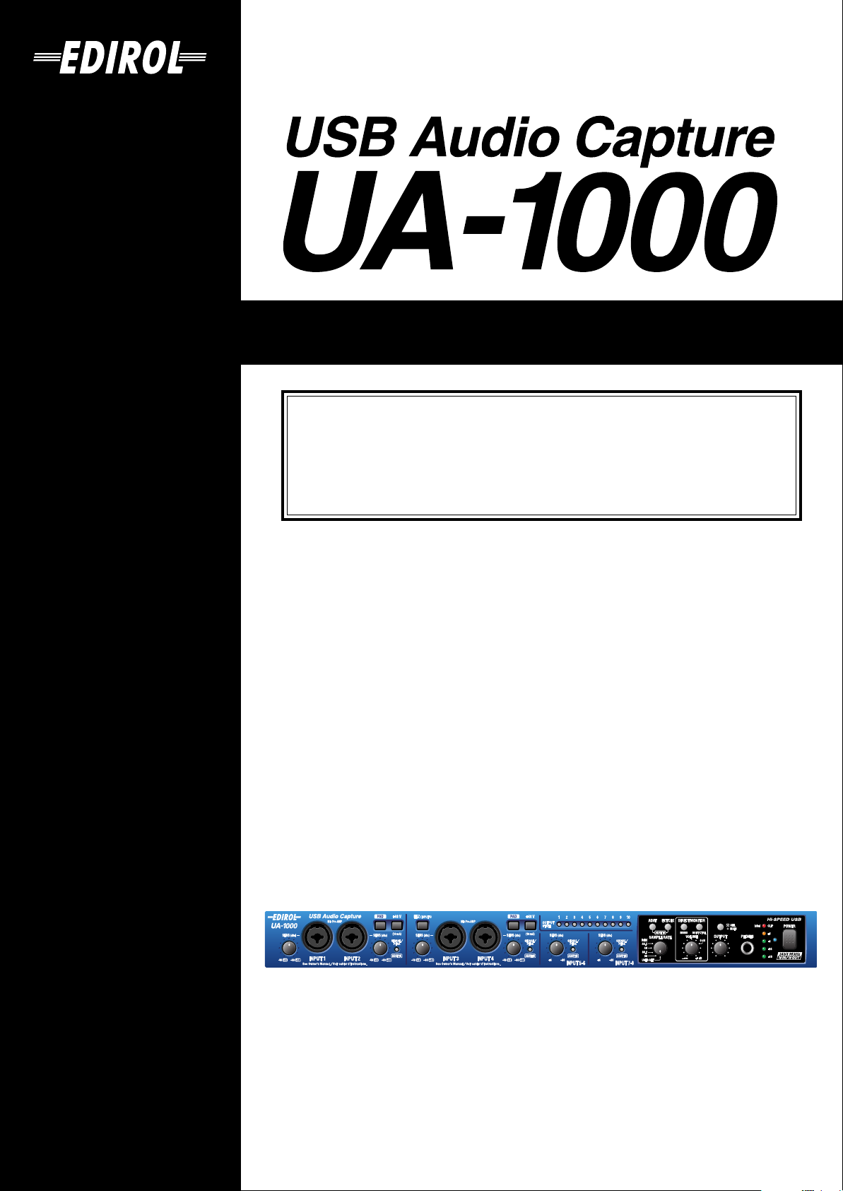
Owner’s Manual
Before using this unit, carefully read the sections entitled: “IMPORTANT
SAFETY INSTRUCTIONS” (p. 2), “USING THE UNIT SAFELY” (pp. 3–4), and
“IMPORTANT NOTES” (pp. 5–6). These sections provide important information
concerning the proper operation of the unit. Additionally, in order to feel
assured that you have gained a good grasp of every feature provided by your
new unit, Owner’s Manual should be read in its entirety. The manual should be
saved and kept on hand as a convenient reference.
Copyright © 2003 ROLAND CORPORATION
All rights reserved. No part of this publication may be reproduced in any form without the
written permission of ROLAND CORPORATION.
CAUTION
RISK OF ELECTRIC SHOCK
DO NOT OPEN
ATTENTION: RISQUE DE CHOC ELECTRIQUE NE PAS OUVRIR
CAUTION: TO REDUCE THE RISK OF ELECTRIC SHOCK,
DO NOT REMOVE COVER (OR BACK).
NO USER-SERVICEABLE PARTS INSIDE.
REFER SERVICING TO QUALIFIED SERVICE PERSONNEL.
The lightning flash with arrowhead symbol, within an
equilateral triangle, is intended to alert the user to the
presence of uninsulated “dangerous voltage” within the
product’s enclosure that may be of sufficient magnitude to
constitute a risk of electric shock to persons.
The exclamation point within an equilateral triangle is
intended to alert the user to the presence of important
operating and maintenance (servicing) instructions in the
literature accompanying the product.
INSTRUCTIONS PERTAINING TO A RISK OF FIRE, ELECTRIC SHOCK, OR INJURY TO PERSONS.
IMPORTANT SAFETY INSTRUCTIONS
SAVE THESE INSTRUCTIONS
WARNING - When using electric products, basic precautions should always be followed, including the following:
1. Read these instructions.
2. Keep these instructions.
3. Heed all warnings.
4. Follow all instructions.
5. Do not use this apparatus near water.
6. Clean only with a dry cloth.
7. Do not block any of the ventilation openings. Install in
accordance with the manufacturers instructions.
8. Do not install near any heat sources such as radiators,
heat registers, stoves, or other apparatus (including
amplifiers) that produce heat.
9. Do not defeat the safety purpose of the polarized or
grounding-type plug. A polarized plug has two blades with
one wider than the other. A grounding type plug has two
blades and a third grounding prong. The wide blade or the
third prong are provided for your safety. When the provided
plug does not fit into your outlet, consult an electrician for
replacement of the obsolete outlet.
WARNING:
IMPORTANT:
As the colours of the wires in the mains lead of this apparatus may not correspond with the coloured markings identifying
the terminals in your plug, proceed as follows:
The wire which is coloured GREEN-AND-YELLOW must be connected to the terminal in the plug which is marked by the
letter E or by the safety earth symbol or coloured GREEN or GREEN-AND-YELLOW.
The wire which is coloured BLUE must be connected to the terminal which is marked with the letter N or coloured BLACK.
The wire which is coloured BROWN must be connected to the terminal which is marked with the letter L or coloured RED.
THIS APPARATUS MUST BE EARTHED
THE WIRES IN THIS MAINS LEAD ARE COLOURED IN ACCORDANCE WITH THE FOLLOWING CODE.
GREEN-AND-YELLOW: EARTH, BLUE: NEUTRAL, BROWN: LIVE
10. Protect the power cord from being walked on or pinched
particularly at plugs, convenience receptacles, and the
point where they exit from the apparatus.
11. Only use attachments/accessories specified by the
manufacturer.
12. Never use with a cart, stand, tripod, bracket,
or table except as specified by the
manufacturer, or sold with the apparatus.
When a cart is used, use caution when
moving the cart/apparatus combination to
avoid injury from tip-over.
13. Unplug this apparatus during lightning storms or when
unused for long periods of time.
14. Refer all servicing to qualified service personnel. Servicing
is required when the apparatus has been damaged in any
way, such as power-supply cord or plug is damaged, liquid
has been spilled or objects have fallen into the apparatus,
the apparatus has been exposed to rain or moisture, does
not operate normally, or has been dropped.
For the U.K.
2
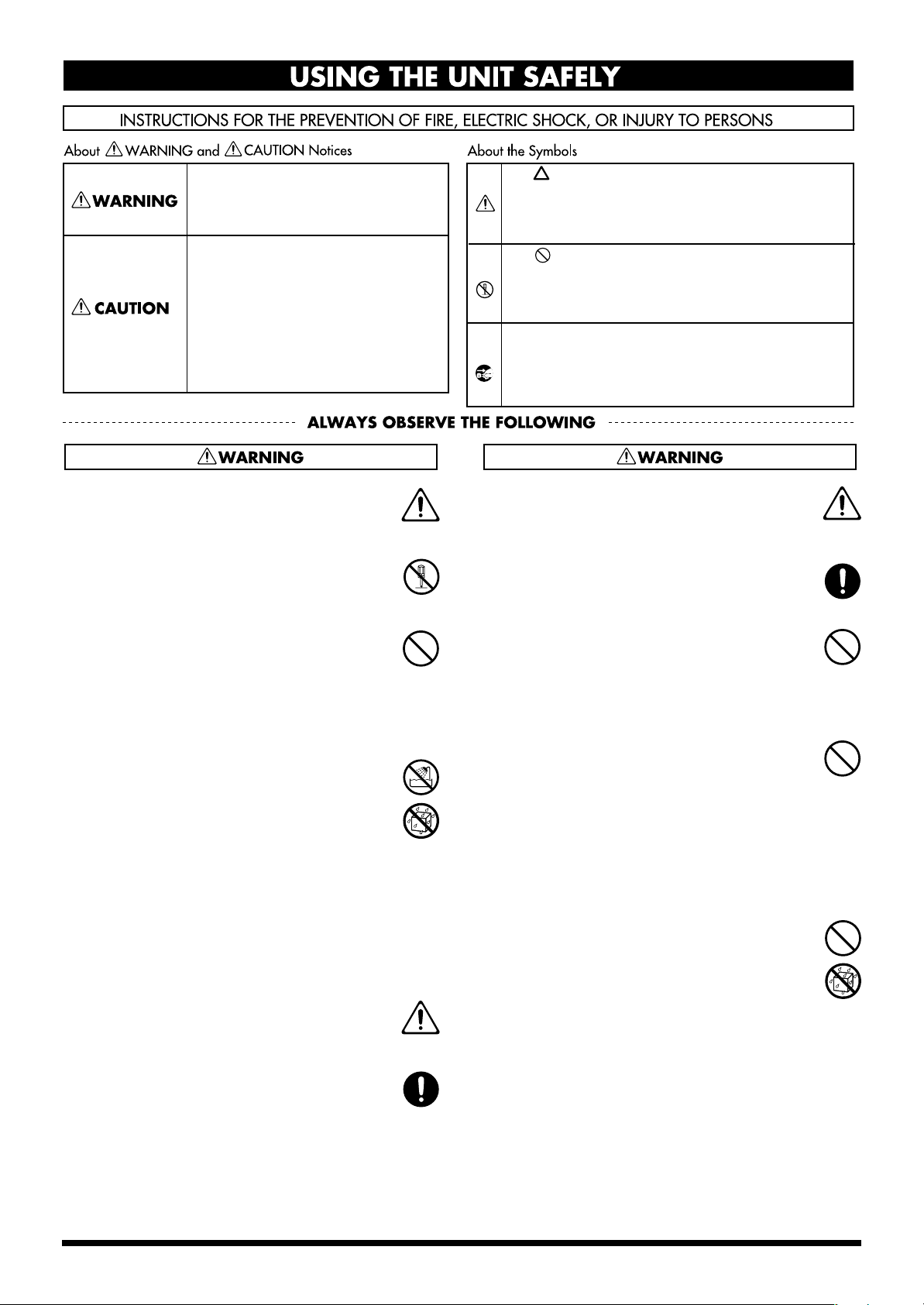
USING THE UNIT SAFELY
Used for instructions intended to alert
the user to the risk of death or severe
injury should the unit be used
improperly.
Used for instructions intended to alert
the user to the risk of injury or material
damage should the unit be used
improperly.
* Material damage refers to damage or
other adverse effects caused with
respect to the home and all its
furnishings, as well to domestic
animals or pets.
001
• Before using this unit, make sure to read the
instructions below, and the Owner’s Manual.
..........................................................................................................
002a
• Do not open or perform any internal modifications on the unit.
..........................................................................................................
003
• Do not attempt to repair the unit, or replace parts
within it (except when this manual provides
specific instructions directing you to do so). Refer
all servicing to your retailer, the nearest Roland
Service Center, or an authorized Roland
distributor, as listed on the “Information” page.
..........................................................................................................
004
• Never use or store the unit in places that are:
• Subject to temperature extremes (e.g., direct
sunlight in an enclosed vehicle, near a heating
duct, on top of heat-generating equipment); or
are
• Damp (e.g., baths, washrooms, on wet floors);
or are
• Humid; or are
• Exposed to rain; or are
• Dusty; or are
• Subject to high levels of vibration.
..........................................................................................................
005
• This unit should be used only with a rack or stand
that is recommended by Roland.
The symbol alerts the user to important instructions
or warnings.The specific meaning of the symbol is
determined by the design contained within the
triangle. In the case of the symbol at left, it is used for
general cautions, warnings, or alerts to danger.
The symbol alerts the user to items that must never
be carried out (are forbidden). The specific thing that
must not be done is indicated by the design contained
within the circle. In the case of the symbol at left, it
means that the unit must never be disassembled.
The ● symbol alerts the user to things that must be
carried out. The specific thing that must be done is
indicated by the design contained within the circle. In
the case of the symbol at left, it means that the powercord plug must be unplugged from the outlet.
008a
• The unit should be connected to a power supply
only of the type described in the operating instructions, or as marked on the side of unit.
..........................................................................................................
008e
• Use only the attached power-supply cord.
..........................................................................................................
009
• Do not excessively twist or bend the power cord,
nor place heavy objects on it. Doing so can
damage the cord, producing severed elements and
short circuits. Damaged cords are fire and shock
hazards!
..........................................................................................................
010
• This unit, either alone or in combination with an
amplifier and headphones or speakers, may be
capable of producing sound levels that could
cause permanent hearing loss. Do not operate for
a long period of time at a high volume level, or at
a level that is uncomfortable. If you experience
any hearing loss or ringing in the ears, you should
immediately stop using the unit, and consult an
audiologist.
..........................................................................................................
011
• Do not allow any objects (e.g., flammable material,
coins, pins); or liquids of any kind (water, soft
drinks, etc.) to penetrate the unit.
..........................................................................................................
..........................................................................................................
006
• When using the unit with a rack or stand recommended by Roland, the rack or stand must be
carefully placed so it is level and sure to remain
stable. If not using a rack or stand, you still need
to make sure that any location you choose for
placing the unit provides a level surface that will
properly support the unit, and keep it from
wobbling.
..........................................................................................................
3
012a:
• Immediately turn the power off, remove the
power cord from the outlet, and request servicing
by your retailer, the nearest Roland Service
Center, or an authorized Roland distributor, as
listed on the “Information” page when:
• The power-supply cord, or the plug has been
damaged; or
• If smoke or unusual odor occurs
• Objects have fallen into, or liquid has been
spilled onto the unit; or
• The unit has been exposed to rain (or otherwise
has become wet); or
• The unit does not appear to operate normally or
exhibits a marked change in performance.
..........................................................................................................
013
• In households with small children, an adult
should provide supervision until the child is
capable of following all the rules essential for the
safe operation of the unit.
..........................................................................................................
014
• Protect the unit from strong impact.
(Do not drop it!)
..........................................................................................................
015
• Do not force the unit’s power-supply cord to share
an outlet with an unreasonable number of other
devices. Be especially careful when using
extension cords—the total power used by all
devices you have connected to the extension
cord’s outlet must never exceed the power rating
(watts/amperes) for the extension cord. Excessive
loads can cause the insulation on the cord to heat
up and eventually melt through.
..........................................................................................................
016
• Before using the unit in a foreign country, consult
with your retailer, the nearest EDIROL/Roland
Service Center, or an authorized EDIROL/Roland
distributor, as listed on the “Information” page.
..........................................................................................................
023
• DO NOT play a CD-ROM disc on a conventional
audio CD player. The resulting sound may be of a
level that could cause permanent hearing loss.
Damage to speakers or other system components
may result.
..........................................................................................................
026
• Do not put anything that contains water (e.g.,
flower vases) on this unit. Also, avoid the use of
insecticides, perfumes, alcohol, nail polish, spray
cans, etc., near the unit. Swiftly wipe away any
liquid that spills on the unit using a dry, soft cloth.
..........................................................................................................
101a
• The unit should be located so that its location or
position does not interfere with its proper ventilation.
..........................................................................................................
102b
• Always grasp only the plug on the power-supply
cord when plugging into, or unplugging from, an
outlet or this unit.
..........................................................................................................
103a:
• At regular intervals, you should unplug the power
plug and clean it by using a dry cloth to wipe all
dust and other accumulations away from its
prongs. Also, disconnect the power plug from the
power outlet whenever the unit is to remain
unused for an extended period of time. Any
accumulation of dust between the power plug and
the power outlet can result in poor insulation and
lead to fire.
..........................................................................................................
104
• Try to prevent cords and cables from becoming
entangled. Also, all cords and cables should be
placed so they are out of the reach of children.
..........................................................................................................
106
• Never climb on top of, nor place heavy objects on
the unit.
..........................................................................................................
107b
• Never handle the power cord or its plugs with wet
hands when plugging into, or unplugging from,
an outlet or this unit.
..........................................................................................................
108a
• Before moving the unit, disconnect the power
plug from the outlet, and pull out all cords from
external devices.
..........................................................................................................
109a
• Before cleaning the unit, turn off the power and
unplug the power cord from the outlet (p. **).
..........................................................................................................
110a
• Whenever you suspect the possibility of lightning
in your area, pull the plug on the power cord out
of the outlet.
..........................................................................................................
118
• Whenever you've removed any screws—whether
it be when installing a rackmount adaptor—be
sure to place the screws out of reach of small
children, so they won't be swallowed accidentally.
..........................................................................................................
120
• Always turn the phantom power off when
connecting any device other than condenser
microphones that require phantom power. You
risk causing damage if you mistakenly supply
phantom power to dynamic microphones, audio
playback devices, or other devices that don't
require such power. Be sure to check the specifications of any microphone you intend to use by
referring to the manual that came with it.
4
(This instrument's phantom power: 48 V DC, 10 mA Max x 2
systems)
..........................................................................................................

IMPORTANT NOTES
291b
In addition to the items listed under “IMPORTANT SAFETY INSTRUCTIONS” and “USING THE UNIT SAFELY” on pages 2
and 4, please read and observe the following:
Power Supply
301
• Do not use this unit on the same power circuit with any
device that will generate line noise (such as an electric
motor or variable lighting system).
307
• Before connecting this unit to other devices, turn off the
power to all units. This will help prevent malfunctions
and/or damage to speakers or other devices.
308
• Although the LCD and LEDs are switched off when the
POWER switch is switched off, this does not mean that the
unit has been completely disconnected from the source of
power. If you need to turn off the power completely, first
turn off the POWER switch, then unplug the power cord
from the power outlet. For this reason, the outlet into
which you choose to connect the power cord’s plug
should be one that is within easy reach.
Placement
351
• Using the unit near power amplifiers (or other equipment
containing large power transformers) may induce hum.
To alleviate the problem, change the orientation of this
unit; or move it farther away from the source of interference.
352a
• This device may interfere with radio and television
reception. Do not use this device in the vicinity of such
receivers.
352b
• Noise may be produced if wireless communications
devices, such as cell phones, are operated in the vicinity of
this unit. Such noise could occur when receiving or initiating a call, or while conversing. Should you experience
such problems, you should relocate such wireless devices
so they are at a greater distance from this unit, or switch
them off.
355b
• When moved from one location to another where the
temperature and/or humidity is very different, water
droplets (condensation) may form inside the unit. Damage
or malfunction may result if you attempt to use the unit in
this condition. Therefore, before using the unit, you must
allow it to stand for several hours, until the condensation
has completely evaporated.
Maintenance
401a
• For everyday cleaning wipe the unit with a soft, dry cloth
or one that has been slightly dampened with water. To
remove stubborn dirt, use a cloth impregnated with a
mild, non-abrasive detergent. Afterwards, be sure to wipe
the unit thoroughly with a soft, dry cloth.
402
• Never use benzine, thinners, alcohol or solvents of any
kind, to avoid the possibility of discoloration and/or
deformation.
Repairs and Data
452
• Please be aware that all data contained in the unit's
memory may be lost when the unit is sent for repairs.
Important data should always be written down on paper.
During repairs, due care is taken to avoid the loss of data.
However, in certain cases (such as when circuitry related
to memory itself is out of order), we regret that it may not
be possible to restore the data, and Roland assumes no
liability concerning such loss of data.
Additional Precautions
551
• Please be aware that the contents of memory can be
irretrievably lost as a result of a malfunction, or the
improper operation of the unit. To protect yourself against
the risk of losing important data, we recommend that you
periodically write down important data you have stored
in the unit's memory on paper.
552
• Unfortunately, it may be impossible to restore the contents
of data that was stored in the unit’s memory once it has
been lost. Roland Corporation assumes no liability
concerning such loss of data.
553
• Use a reasonable amount of care when using the unit’s
buttons, sliders, or other controls; and when using its jacks
and connectors. Rough handling can lead to malfunctions.
556
• When connecting / disconnecting all cables, grasp the
connector itself—never pull on the cable. This way you
will avoid causing shorts, or damage to the cable’s
internal elements.
557
•A small amount of heat will radiate from the unit during
normal operation.
558a
• To avoid disturbing your neighbors, try to keep the unit’s
volume at reasonable levels. You may prefer to use
headphones, so you do not need to be concerned about
those around you (especially when it is late at night).
559a
• When you need to transport the unit, package it in the box
(including padding) that it came in, if possible. Otherwise,
you will need to use equivalent packaging materials.
562
• Use a cable from Roland to make the connection. If using
some other make of connection cable, please note the
following precautions.
• Some connection cables contain resistors. Do not use
cables that incorporate resistors for connecting to this
unit. The use of such cables can cause the sound level
to be extremely low, or impossible to hear. For information on cable specifications, contact the manufacturer of the cable.
5

Handling CD-ROMs
801
• Avoid touching or scratching the shiny underside
(encoded surface) of the disc. Damaged or dirty CD-ROM
discs may not be read properly. Keep your discs clean
using a commercially available CD cleaner.
Copyright
851
• Unauthorized recording, distribution, sale, lending, public
performance, broadcasting, or the like, in whole or in part,
of a work (musical composition, video, broadcast, public
performance, or the like) whose copyright is held by a
third party is prohibited by law.
852a
• When exchanging audio signals through a digital
connection with an external instrument, this unit can
perform recording without being subject to the restrictions
of the Serial Copy Management System (SCMS). This is
because the unit is intended solely for musical production,
and is designed not to be subject to restrictions as long as
it is used to record works (such as your own compositions) that do not infringe on the copyrights of others.
(SCMS is a feature that prohibits second-generation and
later copying through a digital connection. It is built into
MD recorders and other consumer digital-audio
equipment as a copyright-protection feature.)
853
• Do not use this unit for purposes that could infringe on a
copyright held by a third party. We assume no responsibility whatsoever with regard to any infringements of
third-party copyrights arising through your use of this
unit.
* Microsoft and Windows are registered trademarks of Microsoft Corporation.
206e
* The screen shots in this document are used in compliance with the guidelines of the Microsoft Corporation.
206j
* Windows® is known officially as: “Microsoft® Windows® operating system.”
220
* All product names mentioned in this document are trademarks or registered trademarks of their respective owners.
204
6

Contents
USING THE UNIT SAFELY......................................................................3
IMPORTANT NOTES ...............................................................................5
Main features...........................................................................................8
Contents of the package ........................................................................9
Panel Descriptions................................................................................11
Front panel................................................................................................................................................. 11
Rear panel.................................................................................................................................................. 15
Preparations for using the UA-1000....................................................18
Installing the driver.................................................................................................................................. 18
Giving priority to background services ................................................................................................22
Driver settings........................................................................................................................................... 23
Basic connections and settings ..........................................................26
Basic connections......................................................................................................................................26
Recording a mic or guitar........................................................................................................................ 27
Recording onto an external ADAT device............................................................................................29
Capturing sound from an external ADAT device ............................................................................... 30
Monitoring 5.1 channel sound................................................................................................................31
Inserting an external effects processor .................................................................................................. 32
Recording a digital input signal ............................................................................................................. 33
Synchronizing to the word clock input................................................................................................. 34
Various settings ....................................................................................36
Internal blocks of the UA-1000 ............................................................................................................... 36
UA-1000 Control Panel............................................................................................................................ 36
Adjusting the audio latency....................................................................................................................40
Using ASIO Direct Monitor ....................................................................................................................40
Synchronization settings .....................................................................41
About the ADAT mode switch and external clock switch................................................................. 41
System settings ....................................................................................44
Restoring the factory settings (Factory Reset)......................................................................................44
Troubleshooting....................................................................................45
Problems related to the USB driver .......................................................................................................45
Deleting the driver ...................................................................................................................................45
Problems related to the UA-1000 ...........................................................................................................46
Main specifications...............................................................................50
Block diagram .......................................................................................51
INDEX .....................................................................................................53
7

Main features
480 Mbps transfer speed with hi-speed USB (USB 2.0), supporting
10 IN/10 OUT at superb 24-bit/96 kHz audio quality
Ten independent channels of simultaneous recording and playback are supported with superb 24-bit/96 kHz
audio quality.
If your computer has a USB 2.0 connector, you can implement a cutting-edge recording environment by
connecting a single USB cable.
Four channels of high-performance mic preamp
High-performance mic preamp equivalent to those used on the Roland VS-2480 deliver transparent sound.
The UA-1000 uses the same carefully selected analog parts as on the Roland VS-2480, giving you great audio
quality and plenty of recording headroom.
A rich array of inputs and outputs in a single rack space
Four TRS/XLR combo jacks with phantom power, a high-impedance (Hi-Z) jack for direct connection of a
guitar or bass, and optical/coaxial digital input/output connectors are provided.
The optical jacks can also be used as an eight-channel ADAT interface (*).
In addition, the UA-1000 provides four input/output jacks for effect insertion, MIDI input/output, and word
clock input/output jacks for precise recording synchronization with external digital devices.
* When the UA-1000 is not connected to a computer, it can function as a multi-channel analog <-> digital
converter or an ADAT <-> analog converter.
* The UA-1000’s analog inputs cannot be used while in ADAT recording mode.
Built-in digital mixer
The internal digital mixer can be controlled directly from the UA-1000 Control Panel on your computer.
The Direct Monitor function allows realtime monitoring of the ten channels of input without passing them
through your computer software.
WDM and ASIO 2.0 compatible
WDM and ASIO 2.0 compatible low-latency driver is provided.
The driver delivers superb performance with any DAW application, such as SONAR and Cubase.
MIDI interface with FPT ensures high speed and low jitter
FPT (Fast Processing Technology of MIDI Transmission) ensures stable, high-speed transmission and
reception with consistent latency and minimal jitter, regardless of the density of MIDI data.
8

Contents of the package
■
UA-1000
fig.ua1000
■
Power cord
This is the only power cord you should use with the UA-1000. Do not use any power cord other than the
supplied one, since doing so may cause malfunction.
■
USB cable
Use this to connect the USB connector of your computer with the USB connector of the UA-1000.
* Please use only the included USB cable. If you require a replacement due to loss or damage, please contact a “EDIROL/
Roland Service Center” listed in the “Information” section at the end of this manual.
■
Owner’s Manual
This is the manual you are reading. Please keep it on hand for reference.
■
CD-ROM
* You must read the license agreement before opening the CD-ROM. Opening the CD-ROM case will be considered
* Do not touch the recorded (unprinted) surface of the disc or allow it to be scratched. Doing so may render the disc
This contains the driver required in order to use the UA-1000.
acceptance of the license agreement.
unreadable. If the disc gets dirty, use a commercially available CD cleaner to clean it.
Do not play back the CD-ROM in a conventional audio CD player. Doing so may produce high-volume sound
that can damage your hearing and/or speakers.
9
Contents of the package
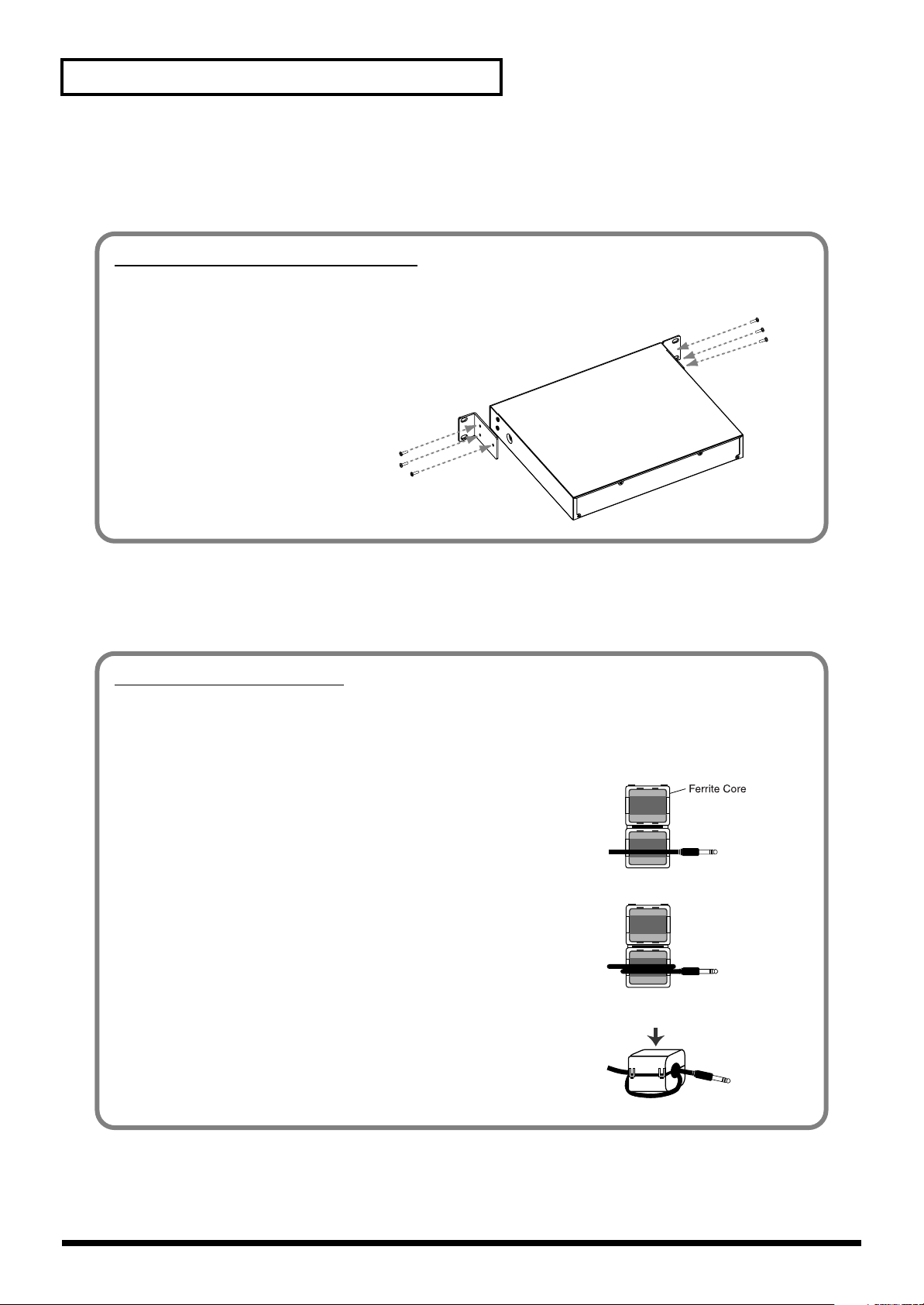
Attaching the Ferrite Core
Before using headphones, make sure to attach the ferrite core.
If you will be using headphones, please follow the instructions below to clamp the supplied ferrite core over
the cord. Afterwards, make sure to leave it on the cord, since it serves in blocking electromagnetic noise.
fig.ferraite-1
■
Rackmount adaptors (two pcs.)
Use this when you want to install the UA-1000 in an audio rack. Two rack ears are included.
Attaching the rackmount adaptors
If you want to install the UA-1000 in a rack, attach the rackmount adaptors as shown in the diagram.
fig.angle
1. Remove three screws (on each side)
from the right and left panels of the
UA-1000.
2. Using the screws you removed in
step 1, attach the rackmount
brackets to the UA-1000.
* You must use the screws that you
removed. Do not use any other screws.
■
Ferrite Core (for 230V and 240V)
The ferrite core should be attached to the cord of your headphones.
1. Open the ferrite core and position it over the cord.
* Make sure to position it so it’s close to the plug.
fig.ferraite-2
2. Wrap the cord around the ferrite core; one turn is enough.
fig.ferraite-3
3. Close it firmly; you should hear a distinct sound as it clicks shut.
* Take care not to get your fingers pinched when attaching the ferrite core.
* Make sure you don’t apply undue force and damage the cord when clamping on
the ferrite core.
10
Panel Descriptions
fig.panel-input
1:GND
2:HOT
3:COLD
GND(SLEEVE)
HOT(TIP)
COLD(RING)
XLR plug
TRS phone
plug
(balanced)
Phone plug
(unbalanced)
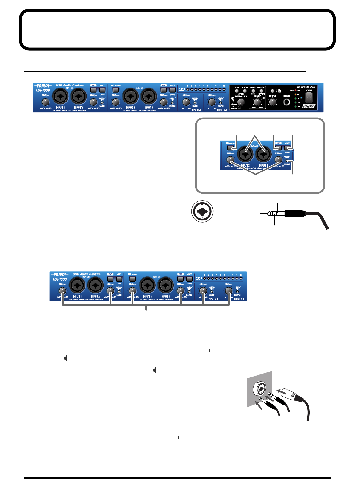
Front panel
fig.front
1.
Combo input jacks 1–4
These are analog audio input jacks with high-quality
preamps. Either XLR type or phone type jacks can be
connected here, as appropriate for the equipment you are
using. Balanced or unbalanced connections are supported.
The XLR type jacks provide 48 V phantom power, allowing
you to connect phantom-powered condenser mics. In this
case, turn on the phantom power switch.
fig.XLR-TRS
* This instrument is equipped with balanced (XLR/TRS) type input
jacks. Wiring diagrams for these jacks are shown on the right.
Make connections after first checking the wiring diagrams of other
equipment you intend to connect.
1
6
4
3
25
2.
Input sensitivity knobs
These adjust the input level of the signals that are input to front panel
jacks 5–8
fig.sens
.
combo input jacks 1–4
2
3.
Phantom power switches 1, 2 (PHANTOM 48 V)
These are on/off switches for the phantom power that is supplied to the XLR type connectors of
1–2
and
3–4
. Phantom power is on when the switch is pressed inward ( ), and off when the switch is in the outward
position ( ).
fig.jack-type
* You must turn phantom power off (button in the outward position) unless a condenser
microphone requiring a phantom power supply is connected to the XLR type jacks.
Malfunctions will occur if you supply phantom power to a dynamic microphone or to an
audio playback device. For details on the specifications of your microphone, refer to the
owner’s manual for your microphone.
(The UA-1000 supplies phantom power at DC 48 V, maximum 10 mA x 2 systems)
and rear panel
combo input jacks
input
4.
Gain select switches (PAD)
These switch the input level. Turn these on (button in the inward position) if you connect devices that have a high
output gain.
11
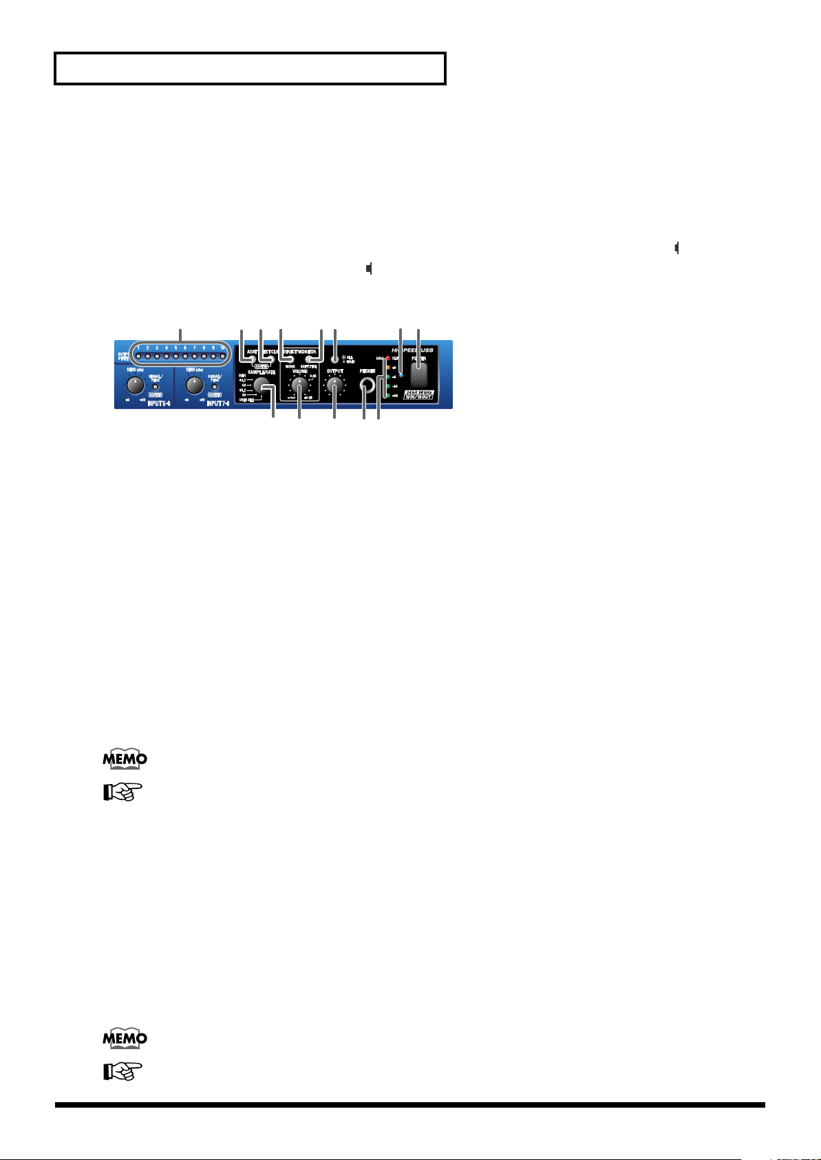
Panel Descriptions
5.
Input peak indicators
These indicate whether distortion is occurring in the sound being input to each input jack. The peak indicators will
light red at a level before the sound begins to distort (-6 dB). Adjust the corresponding
output level of your equipment so that the peak indicators do not light red.
6.
Input impedance select switch
For the phone jack input of
position)) or low impedance (Lo-Z (button in the outward position)), as appropriate for the device that is
connected. Select high impedance (Hi-Z) if you have connected a guitar or bass.
fig.direct-monitor
7 8 11 129
combo input jack 3
14
, you can select either high impedance (Hi-Z (button in the inward
1918
input sensitivity knob
or the
10 13
7.
Output indicators
If audio data is being output from the UA-1000, the output indicator for the jack from which audio data is being
output will light. For example, if audio data is being output from output jack 1, output indicator
Indicators
This provides a convenient way to check the settings of the UA-1000’s internal patch bay. For details, refer to
“Internal blocks of the UA-1000”
8.
ADAT mode switch
When you press the ADAT mode switch, the ADAT mode switch will light and the UA-1000 will be in ADAT Output
mode; ADAT format signals will be output from the optical digital output jack.
If you simultaneously press the ADAT mode switch and the external clock switch, the PEAK/SIG/ADAT IN
indicators will all light orange, and the UA-1000 will be in ADAT Input/Output mode; ADAT format signals will be
input from the optical input jack.
* If you are using ADAT mode, you must set the UA-1000 to 44.1 kHz or 48 kHz. If a setting other than 44.1 kHz or 48 kHz is
selected, ADAT mode will not be available; pressing the ADAT mode switch will not cause the ADAT mode switch to light.
“9”
and
“10”
will light to indicate output from the digital output connector.
(p. 36).
Turning off the power of the UA-1000 will not change the setting of this switch.
For more about the ADAT mode switch, refer to
switch”
(p. 41).
15 16 17
“1”
will light green.
“About the ADAT mode switch and external clock
9.
External clock switch
Turn this on if you want the UA-1000 to synchronize to a word clock signal from an external device or to a digital
signal from the digital input jack. If synchronization is occurring normally, the external clock switch will light, and
the UA-1000 will be in external clock mode. If the external clock switch is blinking, synchronization has not been
achieved.
You must be sure to input a signal which has the frequency that matches the setting of the sampling frequency select
switch.
* If both the word clock input connector and the digital input connector are connected simultaneously, the word clock input
connector will take priority.
* If you are recording a digital signal, the external clock switch must be turned on.
Turning off the power of the UA-1000 will not change the setting of this switch.
For more about the external clock switch, refer to
switch”
(p. 41).
“About the ADAT mode switch and external clock
12
Panel Descriptions
10.
Sampling frequency select switch
This selects the sampling frequency at which audio data will be recorded and played back.
In order for this setting to take effect, you must exit all applications and turn the power of the UA-1000 off, then on
again.
The sampling frequency select switch must be set to match the sampling frequency of the application you are using.
If you are using external clock mode, this must also match the sampling frequency of your external device.
* If you are using the UA-1000 in ADAT mode, set this to 44.1 kHz or 48 kHz. If this is set to anything other than 44.1 kHz or
48 kHz, ADAT mode will not be available; pressing the ADAT mode switch will not cause the ADAT mode switch to light.
USER SET
UA-1000 Control Panel (p. 36) lets you store the following settings in the UA-1000's internal memory.
• ADAT mode switch • External clock switch
• Sampling frequency select switch • STEREO/MONO select switch
• Direct monitor soft control switch • Output volume select switch
• Monitor mixer and patch bay settings
To call up the settings stored in USER SET, set the
power to the unit.
sampling frequency select switch
to
USER SET
, then cycle the
For more about the internal monitor mixer and patch bay, refer to
11.
STEREO/MONO select switch (Direct monitor section)
This selects whether the input signal will be monitored in stereo or in monaural.
Even if
12.
Direct monitor soft control switch (Direct monitor section)
This selects whether the INPUT MONITOR will be controlled by your software. When lit, the monitor volume, pan,
and on/off settings of each input jack can be controlled from your software. When unlit, signals will be output
without being affected by any settings of the INPUT MONITOR.
This lets you temporarily disable the settings of your software in order to check the state of connections.
For details on controlling the UA-1000 from your computer, refer to
MONO
is selected, the audio signal sent via USB to your computer is stereo.
Turning off the power of the UA-1000 will not change the setting of this switch.
If you have connected a mic or guitar to only one of the
MONO setting.
Turning off the power of the UA-1000 will not change the setting of this switch.
For details, refer to
fig.0db
“UA-1000 Control Panel”
(p. 36).
combo input jacks
“UA-1000 Control Panel”
“Various settings”
, it is convenient to use the
(p. 36).
(p. 36).
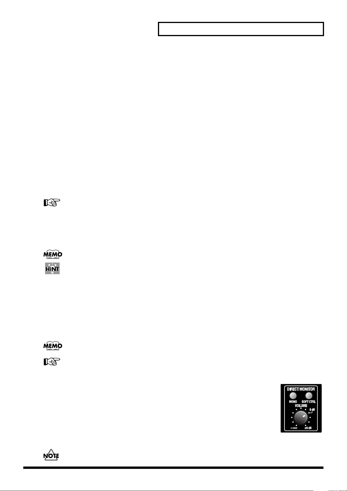
13.
Direct monitor volume (Direct monitor section)
This adjusts the volume at which the input signal is sent to the INPUT MONITOR. If you set the knob
to the
0 dB
position, the volume will be the same as the signal that is being recorded.
* For details on the INPUT MONITOR, refer to
If this knob is turned all the way to the left, the signal level sent to the INPUT MONITOR will be
If you are “thru-ing” the audio data within your computer, or have connected a mixer and are
outputting the input signal directly from the mixer for monitoring, leave this knob turned all the way
to the left.
You can adjust the
off.
direct monitor volume
“UA-1000 Control Panel”
even when the
direct monitor soft control switch
(p. 36).
zero
.
is turned
13
Panel Descriptions
14.
Output volume select switch
This switches the jacks that will be controlled by the output volume knob. Hold this down for two seconds or longer.
If you set this to
signals from the computer mixed).
If you set this to
For details, refer to
15.
Output volume knob
This adjusts the final volume that is output from the UA-1000.
If the
output volume knob select switch
all input signals plus the playback signals from the computer mixed). If you set this to
volume of all output jacks together.
MAIN
, the knob adjusts the volume of the main output signal (i.e., all input signals plus the playback
ALL
, the knob adjusts the volume of all output jacks together.
“Block diagram”
Turning off the power of the UA-1000 will not change the setting of this switch.
Lower the volume of the connected equipment before you change the setting of the output
volume select switch.
(p. 51).
is set to
MAIN
, this knob adjusts the volume of the main output signal (i.e.,
ALL
, the knob adjust the
For details, refer to
16.
Headphone jack
A set of headphones can be connected here. The headphone jack will output the main output signal (i.e., all input
signals plus the playback signals from the computer mixed by the monitor mixer).
Sound will still be output from the master output jacks even if headphones are connected.
For details, refer to
17.
Output level indicators
These LEDs will light to indicate the output level adjusted by the output volume knob. Adjust the input sensitivity
knob of each input jack so that the red LED (CLIP) does not light.
18.
Power indicator
This indicator will light when the power switch is on.
19.
Power switch
fig.power-sw
Press this switch to turn the power on/off.
The power is on when the switch is in the inward position, and off
when the switch is in the outward position.
* Do not turn off the power switch while your audio application is recording or playing. Doing so may cause your application
to freeze.
“Block diagram”
“Internal blocks of the UA-1000”
(p. 51).
(p. 36).
Power is on
when switch is in
Power is off
when switch is out
14
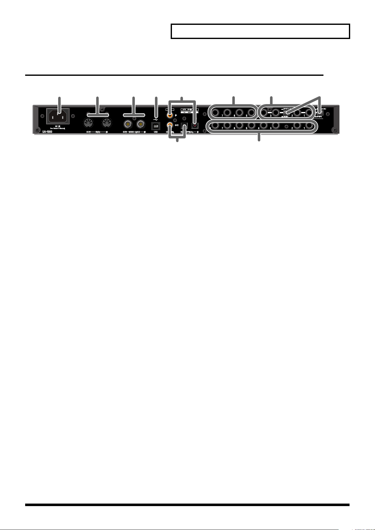
Rear panel
fig.rear
Panel Descriptions
20
20.
AC inlet
Connect the included AC cable here. Plug in the cable firmly so that it does not fall out. For details on current
consumption, refer to
21.
MIDI IN/OUT connectors
Connect these to the MIDI connectors of your MIDI device to receive or transmit MIDI messages.
22.
WORD CLOCK IN/OUT jacks
Use these jacks to synchronize the UA-1000 with a digital recorder.
If you want to synchronize to WORD CLOCK, you must turn on the external clock switch.
23.
USB connector
21
“Main specifications”
22
23
(p. 50).
24 26 27
25
29
28
Use a USB cable to connect the UA-1000 to your computer.
* Do not plug in or unplug the USB cable while your audio application is recording or playing. Doing so may cause the
application to freeze.
24.
Coaxial digital input jack / optical digital input jack
Use these jacks to input digital audio from a CD/MD/DAT, etc. If a digital device is connected to the optical digital
input jack, the optical digital input jack will be given priority; the signal from the coaxial digital input jack will not
be input. Digital signals applied to the digital input connectors are handled as INPUT 9 and 10.
In order to record a digital signal, the external clock switch must be turned on.
If you want to use the optical digital input jack to input ADAT signals, simultaneously press the
and the
from the optical input jack.
25.
Coaxial digital output jack / optical digital output jack
Use these jacks to send digital audio to a digital audio device such as an MD or DAT. Digital signals output from the
digital output connectors are handled as OUTPUT 9 and 10.
If you want to use the optical digital output jack to output ADAT signals, press the
ADAT Output mode, or simultaneously press the
ADAT Input/Output mode. This allows ADAT format signals to be output from the optical input jack.
26.
Input jacks 5–8
external clock switch
to select ADAT Input/Output mode. This allows ADAT format signals to be input
ADAT mode switch
ADAT mode switch
and the
external clock switch
ADAT mode switch
to select
to select
Connect to these jacks when you want to input audio signals from audio devices or MIDI sound modules.
15

Panel Descriptions
27.
Insertion / Input jacks 1–4
These can be used either as insertion jacks or as input jacks.
Turn the Insertion/Input Select switches on/off to select whether these jacks will function as insertion jacks or as
input jacks.
For details, refer to
28.
Insertion / Input jack select switches
Turn the Insertion/Input Select switches on/off to select whether insertion / input jacks 1–4 will function as insertion
jacks or as input jacks.
For details on use, refer to
“Inserting an external effects processor”
“Inserting an external effects processor”
(p. 32).
(p. 32).
Insertion jack mode:
Set the switch to INSERT ( button outward). Insertion/Input jacks 1–4 will function as insertion jacks.
This setting lets you insert external effects processors into the inputs of combo input jacks 1–4 (TRS phone type).
Input jack mode:
Set the switch to INPUT ( button inward). Insertion/Input jacks 1–4 will function as input jacks.
This setting lets you input audio signals from audio devices or MIDI sound modules (+4 dBu fixed, phone type,
unbalanced).
If you use these as input jacks, the input from combo input jacks 1–4 will be turned off.
See also
29.
Output jacks 1–8 (phone)
These are output jacks for analog audio signals.
“Inserting an external effects processor”
(p. 32).
16
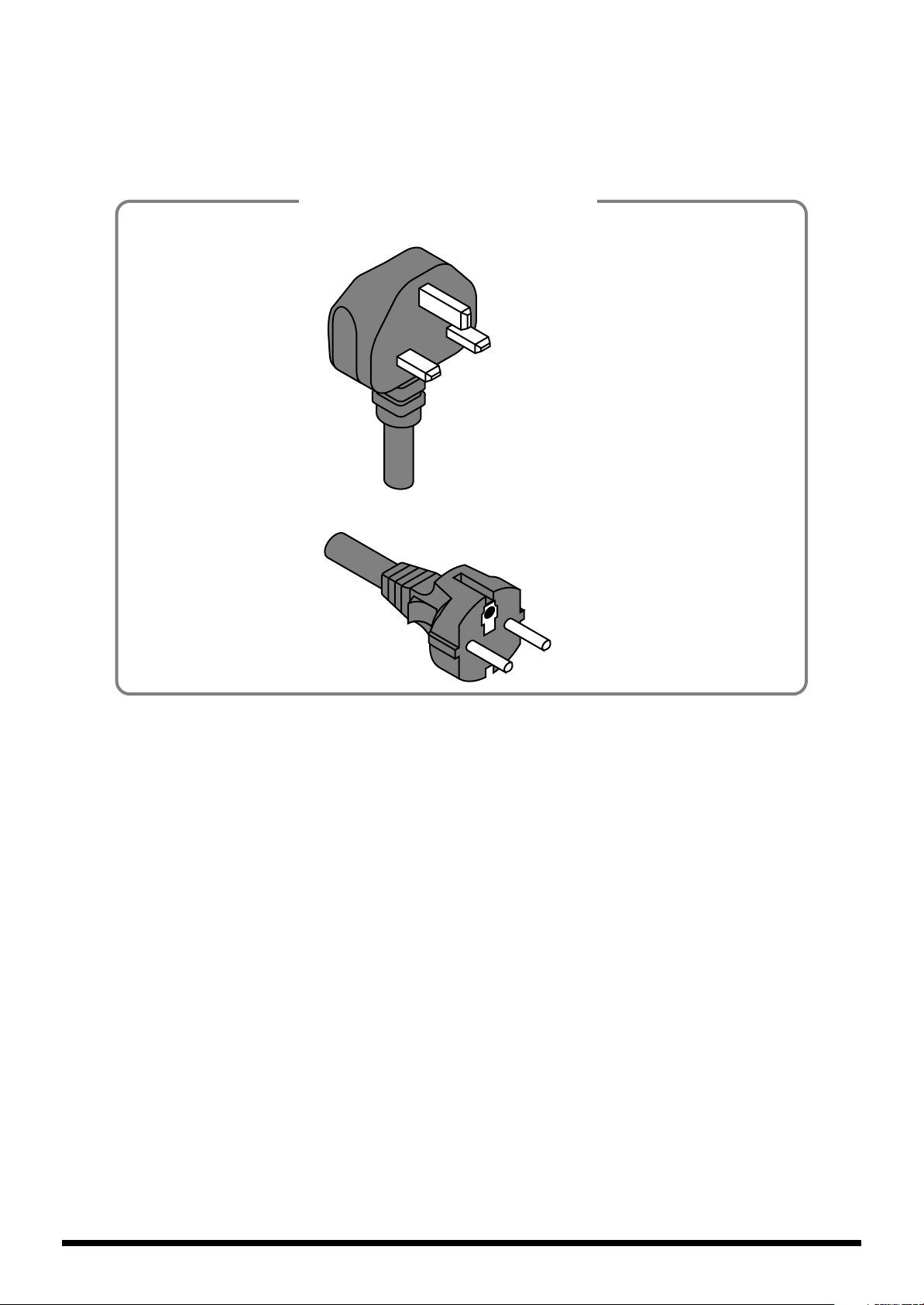
Application of AC230 V
Power Cord
for UK
except for UK
17
 Loading...