

Page 1
V シンバル対応バージョン 取扱説明書
201a
このたびは、ローランド TDW-1 をお買い上げいただき、まことにありがとうございます。
この機器を正しくお使いいただくために、ご使用前に「安全上のご注意」(P.2)と「使用
上のご注意」(P.4)をよくお読みください。また、この機器の優れた機能を十分ご理解い
ただくためにも、取扱説明書をよくお読みください。取扱説明書は必要なときにすぐに見
ることができるよう、手元に置いてください。
02232545 ’02-4-G2-51N
重要
TDW-1 はTD-10 のシステムをバージョン・アップし新しい音色と新し
い機能を追加します。
TD-10 をバージョン・アップする前に、現在お使いのデータを保存してく
ださい!
バージョン・アップを行うと、TD-10 で作成したデータは上書きされ、消えてしまい
ます。データを保存する必要があれば、あらかじめメモリー・カード(M-512E)、ま
たは外部 MIDI機器にデータを保存してください。手順の詳細は、P.6 をご覧ください。
※ この取扱説明書では、TDW-1 によってバージョン・アップした TD-10 を
ジョン・アップした TD-10」
ナル TD-10」
215
※ MIDI は社団法人 音楽電子事業協会(AMEI)の登録商標です。
220
※ 文中記載の会社名及び製品名は、各社の商標または登録商標です。
202
2000 ローランド
©
本書の一部、もしくは全部を無断で複写・転載することを禁じます。
として説明します。
、バージョン・アップしていない TD-10 を
「バー
「オリジ
Page 2
安全上のご注意
警告
注意
安全上のご注意
火災・感電・傷害を防止するには
注意の意味について警告と
取扱いを誤った場合に、使用者が
警告
注意
死亡または重傷を負う可能性が想
定される内容を表わしています。
取扱いを誤った場合に、使用者が
傷害を負う危険が想定される場合
および物的損害のみの発生が想定
される内容を表わしています。
※物的損害とは、家屋・家財およ
び家畜・ペットにかかわる拡大
損害を表わしています。
以下の指示を必ず守ってください
警告
001
● この機器を使用する前に、以下の指示と取扱説
明書をよく読んでください。
..............................................................................................................
002a
● この機器を分解したり、改造したりしないでく
ださい。
図記号の例
は、注意(危険、警告を含む)を表わしていま
す。
具体的な注意内容は、 の中に描かれています。
左図の場合は、「一般的な注意、警告、危険」を
表わしています。
は、禁止(してはいけないこと)を表わしてい
ます。
具体的な禁止内容は、 の中に描かれています。
左図の場合は、「分解禁止」を表わしています。
●は、強制(必ずすること)を表わしています。
具体的な強制内容は、●の中に描かれています。
左図の場合は、「電源プラグをコンセントから抜
くこと」を表わしています。
13
● お子様のいるご家庭で使用する場合、お子様の
取り扱いやいたずらに注意してください。必ず
大人のかたが、監視/指導してあげてください。
..............................................................................................................
014
● この機器を落としたり、この機器に強い衝撃を
与えないでください。
0
..............................................................................................................
003
● 修理/部品の交換などで、取扱説明書に書かれ
ていないことは、絶対にしないでください。必
ずお買い上げ店またはローランド・サービスに
相談してください。
..............................................................................................................
004
● 次のような場所での使用や保存はしないでくだ
さい。
○ 温度が極端に高い場所(直射日光の当たる場
所、暖房機器の近く、発熱する機器の上など)
○ 水気の近く(風呂場、洗面台、濡れた床など)
や湿度の高い場所
○ 雨に濡れる場所
○ ホコリの多い場所
○ 振動の多い場所
..............................................................................................................
011
● この機器に、異物(燃えやすいもの、硬貨、針
金など)や液体(水、ジュースなど)を絶対に
入れないでください。
..............................................................................................................
..............................................................................................................
022c
● TDW-1 を取り付ける前に、TD-10の電源を切っ
て電源プラグをコンセントから外してくださ
い。
106
● この機器の上に乗ったり、機器の上に重いもの
を置かないでください。
..............................................................................................................
1115b
● 指定の機器(TD-10)だけに取り付け、取り付
け時には指定されたネジだけを外してくださ
い。
..............................................................................................................
2
Page 3

目次
はじめに....................................................................................................4
使用上のご注意............................................................................................................................................... 4
この取扱説明書の読みかた........................................................................................................................... 4
主な特長............................................................................................................................................................4
注意点(重要).................................................................................................................................................. 5
バージョン・アップしていないTD-10 との互換性について.............................................................. 5
第 1 章 TD-10 をバージョン・アップする................................................6
バージョン・アップの前にデータを保存する..........................................................................................6
エクスパンション・ボードTDW-1 の取り付けかた.............................................................................. 8
TDW-1 のプログラムを読み込む..............................................................................................................10
保存したデータをTD-10 に戻す..............................................................................................................10
第 2 章 トリガリングの改良について .....................................................11
トリガー・バンクとトリガー・タイプ設定............................................................................................11
弱打感度の改良.............................................................................................................................................12
クロス・スティック奏法に対応................................................................................................................12
全てのトリガー・インプットで打点位置検出に対応...........................................................................12
クロストークによる誤発音を防止............................................................................................................13
第 3 章 V シンバルについて....................................................................14
ライド用V シンバルCY-15R の接続と設定について .........................................................................14
第 4 章 追加機能について .......................................................................15
付属ラベルの貼りかた.................................................................................................................................15
各種ショートカット機能.............................................................................................................................15
トリガー・チェイスのロック機能............................................................................................................15
グループ・フェーダーの切り替え機能....................................................................................................16
グローバル・アウトプット/パンの設定................................................................................................16
ペダル・ハイハットの音量調整................................................................................................................17
コンプレッサーの改良.................................................................................................................................17
インストのグループ選択.............................................................................................................................18
ハイハット・コントロール・ペダルを使ったピッチ・コントロール機能......................................18
パッド・パターン・ベロシティー・スイッチ........................................................................................18
ドラム・キットごとのバルク・ダンプ機能............................................................................................18
ハイハット・ノート・ナンバー・ボーダー............................................................................................19
クリック(メトロノーム)用音色の追加................................................................................................19
「DRUM KIT」画面のマスター EQ 表示 ..................................................................................................19
「TRIGGER ADVANCED」画面のベロシティー・メーター...............................................................19
シンバル・エディット画面のアイコン....................................................................................................19
第 5 章 応用使用例..................................................................................20
パッドとアコースティック・ドラム間のクロストーク回避法..........................................................20
タップ・パターンの録音から演奏まで....................................................................................................20
クリック(メトロノーム)音のみを外部MIDI 機器と同期させる方法...........................................21
リム・ショットについて.............................................................................................................................21
各種コピーの一覧表.....................................................................................................................................21
第 6 章 資料編 .........................................................................................22
インスト・リスト.........................................................................................................................................22
ドラム・キット・リスト.............................................................................................................................24
パーカッション・グループ.........................................................................................................................25
プリセット・パターン・リスト................................................................................................................25
メッセージ......................................................................................................................................................26
MIDIインプリメンテーション...................................................................................................................27
ブロック・ダイヤグラム ........................................................................32
3
Page 4

はじめに
使用上のご注意
291a
2 ページに記載されている「安全上のご注意」以外に、次の
ことに注意してください。
修理について
451a
● お客様がこの機器を分解、改造された場合、以後の性能
について保証できなくなります。また、修理をお断りす
る場合もあります。
453
● 当社では、この製品の補修用性能部品(製品の機能を維
持するために必要な部品)を、製造打切後 6 年間保有し
ています。この部品保有期間を修理可能の期間とさせて
いただきます。なお、保有期間が経過した後も、故障箇
所によっては修理可能の場合がありますので、お買い上
げ店、または最寄りのローランド・サービスにご相談く
ださい。
基板の取り扱い
901
● この基板は、静電気により部品が破壊される恐れがあり
ます。基板を取り扱うときは、次の点に注意してくださ
い。
1
○ 基板を持つときは、あらかじめ何らかの金属に触れ
て、体や衣類にたまっている静電気を放電してくだ
さい。
2
○ 基板を持つときは、基板の縁を持ち、部品やコネク
ターの部分に直接手を触れないでください。
主な特長
このボードは TD-10 に音色と機能を追加します。
新しい音色について
新規音色を 360 種類搭載(P.22)
表現力をさらに追求した新しい音色を搭載
•
音素片としてのウェーブを 14MB(メガバイト)搭載
•
本体の 16MB と合わせて合計 30MB になります。
※ 16 ビット・リニア換算
•
ペダル動作による音色制御を改良したハイハット音色
•
タムとシンバルのクオリティーの向上
•
打点位置に対応したタム音色の追加
※ 音色は Spectrasonis 社との共同開発です。
新規ドラム・キットを 50 種類搭載(P.24)
オリジナル TD-10 の50 のプリセット・ドラム・キットと、
TDW-1 で新規に搭載された50 のプリセット・ドラム・
キットから好みのドラム・キットをコピーして使用できます
(P.7)。
新規のプリセット・パターンを搭載(P.25)
この取扱説明書の読みかた
本取扱説明書は、追加された音色と機能について説明してい
ます。TD-10本体の取扱説明書と合わせてお読み下さい。
この取扱説明書では、TDW-1 によってバージョン・アップ
した TD-10 を「バージョン・アップした TD-10」、バー
ジョン・アップしていない TD-10 を「オリジナル TD-10」
として説明します。
962b
※ 製品の仕様および内容は、改良のため予告なく変更する
ことがあります。
985(ディスプレイか画面のどちらかを使う)
※ 本書では、画面を使用して機能説明をしていますが、工
場出荷時の設定(音色名など)と本文中の画面上の設定
は一致していません。あらかじめご了承ください。
新しい機能について
フェーダー・モードを追加、パネルからタムとシンバル
•
の音量を独立して調節可能 (P.16)
ダイレクト・アウトプットのグローバル設定機能の追加
•
(P.16)
ハイハット・コントロール・ペダルによるピッチ・コン
•
トロール機能の追加 (P.18)
•
ペダル・ハイハット音色の音量の調節機能の追加 (P.17)
内蔵コンプレッサーの改良(P.17)
•
コンプレッサーの効き具合を強くしたため、音圧を上げ
たり、音のピークをそろえたり、より積極的な音づくり
に使えるようになりました。
•
すばやい音色選択を可能にするインスト・グループ選択
機能の追加 (P.18)
•
エディット時に便利なトリガー・チェイスのロック機能
を追加 (P.15)
•
各種ショート・カット機能の追加 (P.15)
•
すべてのトリガー・インプットで打点位置検出に対応
(P.12)
4
Page 5

スネア以外のトリガー・インプットでのチューニング表
•
示機能の追加(P.13)
•
1つのドラム・キットだけのバルク・ダンプ機能の追加
(P.18)
•
シーケンサーのパッド・パターン機能にパッド・パター
ン・ベロシティー機能を追加 (P.18)
クリック(メトロノーム)・インストを 4 音追加、合計
•
20 音に拡張 (P.19)
トリガリングを改良し演奏性を向上
センシティビティーとダイナミクスの改良
•
•
KD-120 使用時の弱打のセンシティビティーの改良
•
クロス・スティック奏法への対応(P.12)
(クロス・スティック音の音量調節も可能)
•
PD-120、PD-80R、PD-7/9を使用したリム・ショット
の演奏性を改良
•
最新のパッド(PD-80、PD-80R、KD-80、KD-120)
のトリガー・タイプを追加(P.11)
ローランドの Vシンバル
(CY-15R、CY-14C、CY-12H)
に完全対応
V シンバル用のトリガー・タイプをトリガー・バンク 2
•
にあらかじめ設定(P.11)
V シンバル用のトリガー・タイプ(HH、CrA、CrB、
•
RdA、RdB、CTR)を追加(P.11)
•
チョーク奏法、エッジ・ショット、ベル・ショット
(CY-15Rのみ)に対応(P.14)
•
CY-15R の 3 ウェイ・トリガー(P.14)に対応
CY-15R、CY-14C の打点位置による音色変化に対応
•
(P.12)
はじめに
注意点(重要)
•
バージョン・アップを行うと、TD-10で作成したデータ
は上書きされ、消えてしまいます。データを保存する必
要があれば、あらかじめメモリー・カード(M-512E)、
または外部 MIDI 機器に保存してください。このデータ
はバージョン・アップした TD-10 で使用可能です。
バージョン・アップした TD-10 で保存したデータは、
•
バージョン・アップしていない TD-10 では使用できま
せん。
バージョン・アップした TD-10 は、TDW-1をはずすと
•
動作しません。
バージョン・アップした TD-10を元のバージョンに戻す
•
ことはできません。
バージョン・アップしていない TD-10 との互換性について
オリジナル TD-10 のドラム・キットおよびインストや各種
設定は、バージョン・アップした TD-10 で使用可能です。
ただし、機能の改良に伴い、以下の点についてはバージョ
ン・アップしていない TD-10 とデータ互換性がありません
ので、ご了承ください。
コンプレッサーの効き
•
コンプレッサーをより強く効かせる設定も可能になり、
設定値の効き具合が変更されました (P.17)。
•
トリガー・パラメーター
トリガー・パラメーターの追加と値の効き具合が変更さ
れました (P.11)。
•
パーカッション・グループ1の内容変更
新しいパーカッション音色をアサインしました(P.25)。
•
プリセット・パターンの変更
プリセット・パターンを一部変更し新規に搭載しました
(P.25)。これにより、ドラム・キットに設定されている
パッド・パターンの設定が変更されていることがありま
す。
オリジナル TD-10 のデータを受信したときに、コンプ
レッサーの値は無視され、製品出荷時の標準的な値が設
定されます。トリガー・パラメータの設定は無視されま
す。
5
Page 6

第 1 章 TD-10 をバージョン・アップする
バージョン・アップの前にデータを保存する
重要
TD-10 をバージョン・アップする前に、現在お使いのデータを保存してください!
バージョン・アップを行うと、TD-10 で作成したデータは上書きされ、消えてしまいます。データを保存する必要があれば、
あらかじめメモリー・カード(M-512E)、または外部 MIDI 機器にデータを保存してください。
オリジナル TD-10 で保存したデータは、バージョン・アップした TD-10 で読み込み可能です(P.10)。
オリジナル TD-10 のプリセット・ドラム・キットは、バージョン・アップ後に読み込むことができますので、保存する必
要はありません(P.7)。
データをメモリー・カードに保存する
1.
[SETUP]-[F4(UTIL)]-[F1(SAVE)]を押します。
2.
メモリー・カードの上部にあるプロテクト・スイッチを「OFF」にします。
データを保存するメモリー・カードを、TD-10リア・パネルのメモリー・カード・スロットに差し込みます。
3.
[F4(SAVE)]を押します。
4.
5.
[F4(EXEC)]を押すと、データがメモリー・カードに保存されます。
詳しい手順は、TD-10 取扱説明書の「データをメモリー・カードに保存する」(P.114)をご覧ください。
コピー機能を使って、ドラム・キットを 1 つずつメモリー・カードに保存することができます(TD-10 取扱説明書
P.117)。
データを外部 MIDI 機器に保存する(バルク・ダンプ)
TD-10の MIDI OUT端子と外部 MIDI 機器(保存先)の MIDI IN 端子を、MIDIケーブルで接続します。
1.
[SETUP]-[F2(MIDI)]-[F4(BULK)]を押します。
2.
3.
[INC/DEC]またはVALUE ダイヤルを使って、「ALL」を選びます。
外部 MIDI 機器の録音を開始します。
4.
[F4(EXEC)]を押すと、データの送信が開始されます
5.
詳しい手順は、TD-10 取扱説明書の「外部機器にデータを保存する(バルク・ダンプ)」(P.121)をご覧ください。
6
Page 7
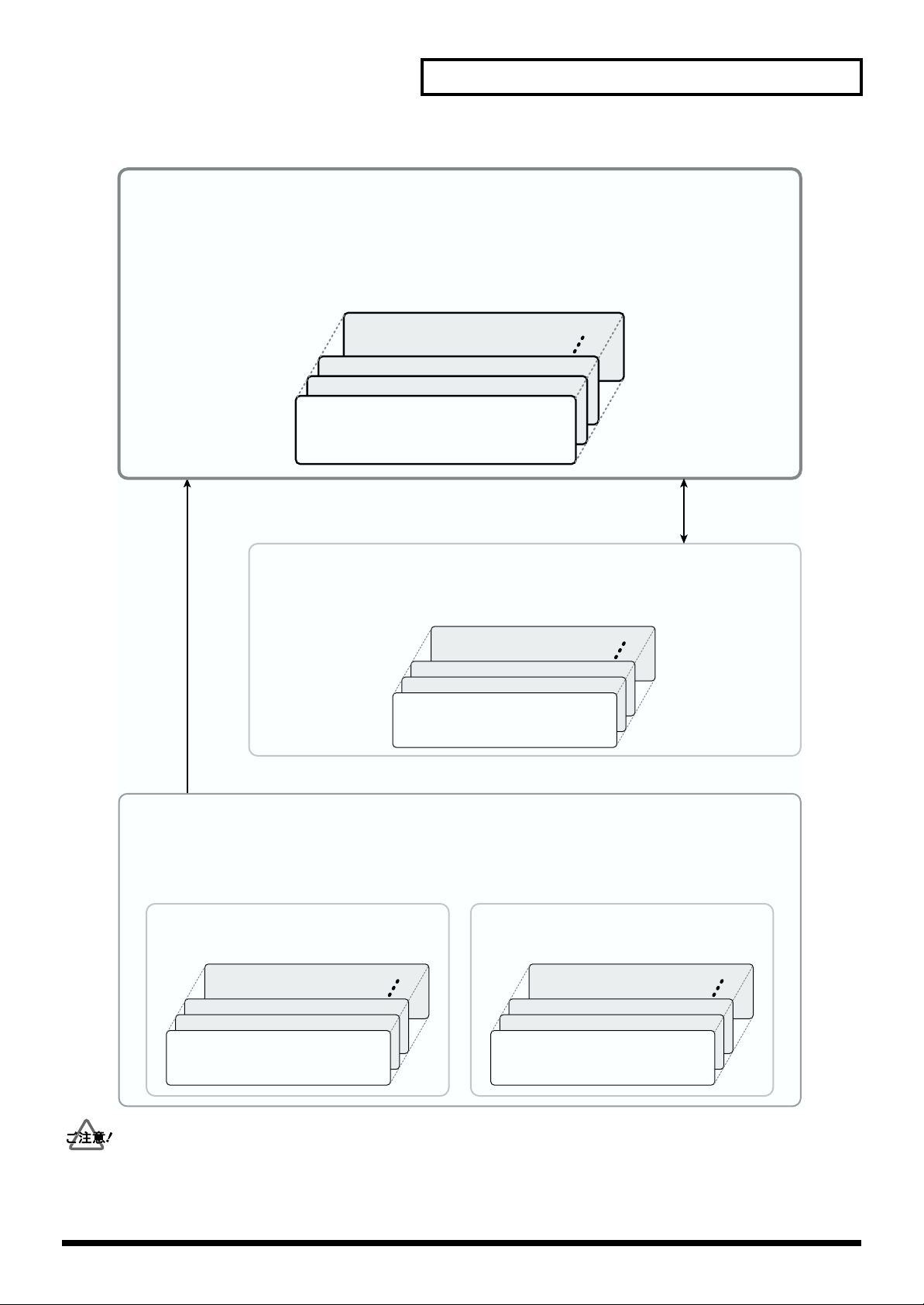
fig.DrumKit.j
第 1 章 TD-10 をバージョン・アップする
User:演奏に使用できるドラム・キット
• 全部で50個のドラム・キットを選んで演奏できます。
•ドラム・キットを編集できます。
※バージョン・アップ後は、TDW-1のプリセット・ドラム・キットがユーザー・ドラム・キットに読み込まれて
います。
KIT 50
KIT 3
KIT 2
USER
ユーザー・ドラム・キット
KIT 1
コピー([KIT]→[TOOLS]→[F1(COPY)])
コピー/
エクスチェンジ
CARD:バージョン・アップしたTD-10で保存したドラム・キット
• 全部で50個のドラム・キットを保存できます。
•ユーザー・ドラム・キットにコピーすると、演奏したり、編集したりすることができます。
KIT 50
KIT 3
KIT 2
CARD(メモリー・カードM-512E)
KIT 1
ドラム・キット・データ
プリセット・ドラム・キット:
ユーザー・ドラム・キットにコピーして使用するドラム・キット
• TDW-1のプリセット・ドラム・キット(50個)とTD-10のプリセット・ドラム・キット(50個)があります。
•ユーザー・ドラム・キットにコピーすると、演奏したり、編集したりすることができます。
TDW-1: TDW-1の製品出荷時の
ドラム・キット
TD-10:TD-10の製品出荷時の
ドラム・キット
KIT 50
KIT 3
KIT 2
TDW-1
KIT 1
プリセット・ドラム・キット
•
オリジナル TD-10 のメモリー・カードのデータはコピー、エクスチェンジできません。「LOAD ALL」のみが可能です。
バージョン・アップしたTD-10 をバージョン・アップ前のバージョン(オリジナル TD-10 の状態)に戻すことはできません。
•
バージョン・アップした TD-10 は、エクスパンション・ボード TDW-1をはずすと一切動作しません。
•
TD-10
プリセット・ドラム・キット
KIT 2
KIT 1
KIT 50
KIT 3
7
Page 8
第 1章 TD-10 をバージョン・アップする
エクスパンション・ボード TDW-1 の取り付けかた
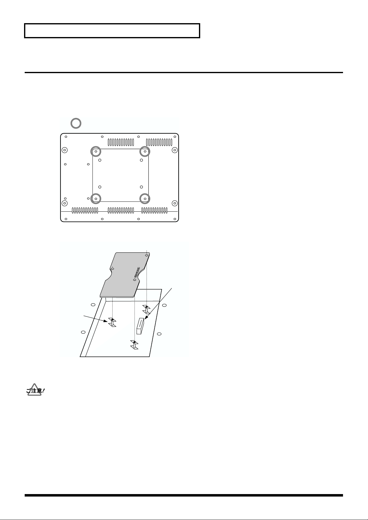
TD-10の底面にはエクスパンション・ボードを取り付けるためのスロットがあります。
TDW-1を取り付ける前に、TD-10 の電源を切って電源プラグをコンセントから外してください。
1.
2.
TD-10の底面の 4 本のネジを外して、カバーを開けます。
fig.00-049aj
取り外すネジ
基板ホルダーを、図のような向きに合わせます。
3.
fig.00-049bj
エクスパンション・ボード
コネクター
基板ホルダー
4.
エクスパンション・ボードのコネクターを、本体のコネクターに完全に差し込みます。このとき 3つの基板ホルダーの頭が、
エクスパンション・ボードから出るようにします。
回路部やコネクター部には手を触れないでください。
•
エクスパンション・ボードを無理に押し込まないでください。装着しにくい場合、いったん基板を外してやり直してくださ
•
い。
8
Page 9
第 1 章 TD-10 をバージョン・アップする
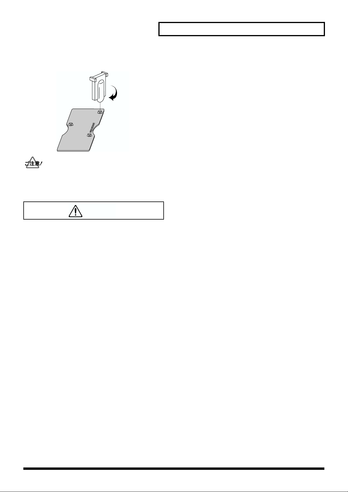
エクスパンション・ボードに付属の固定用具で基板ホルダーを LOCK 方向に回し、エクスパンション・ボードを固定します。
5.
fig.00-049c
LOCK
取り付けを終えたら、正しく取り付けられていることを再度確認してください。
6.
手順 2.で取り外した 4 本のネジでカバーを取り付けます。
警告
● 次のような場合は、直ちに電源を切って電源コードをコンセントから外し、お買い上げ店またはローランド・サービスに修
理を依頼してください。
○異物が内部に入ったり、液体がこぼれたりしたとき
○機器が(雨などで)濡れたとき
○機器に異常や故障が生じたとき
901
● この基板は、静電気により部品が破壊される恐れがあります。基板を取り扱うときは、次の点に注意してください。
○基板を持つときは、あらかじめ何らかの金属に触れて、体や衣類にたまっている静電気を放電してください。
○基板を持つときは、基板の縁を持ち、部品やコネクターの部分に直接手を触れないでください。
9
Page 10
第 1章 TD-10 をバージョン・アップする
TDW-1 のプログラムを読み込む
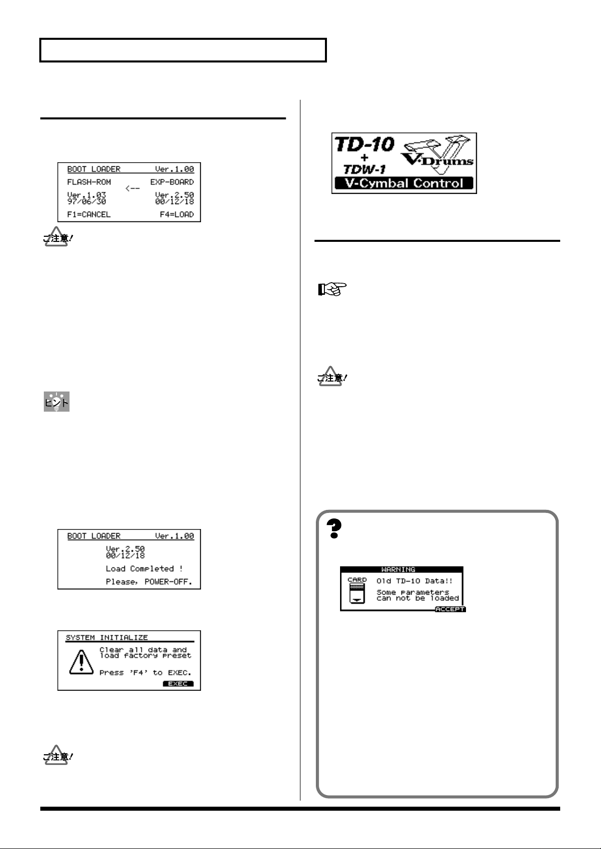
1.
TD-10の電源を入れます。
「BOOT LOADER」画面が表示されます。
fig.LOADscreen80
•
バージョン・アップを行うと、TD-10 で作成したデータは
上書きされ、消えてしまいます。データを保存する必要が
あれば、あらかじめメモリー・カード(M-512E)、また
は外部 MIDI 機器にデータを保存してください。詳しい手
順は、P.6 をご覧ください。
•
バージョン・アップした TD-10 のデータは、オリジナル
TD-10 では使用できません。
バージョン・アップしたTD-10 をバージョン・アップ前の
•
バージョン(オリジナル TD-10 の状態)に戻すことはで
きません。
バージョン・アップをやめるときは、[F1(CANCEL)]
を押します。
2.
[F4(LOAD)]を押すと、バージョン・アップを開始します。
バージョン・アップには、約 35 秒かかります。バージョ
ン・アップが終了するまで、電源を切らないでください。
3.
「LOAD Completed!」画面が表示されたら、TD-10の電
源を切ります。
fig.Completedscreen80
バージョン・アップを行った後、TD-10 の電源を入れると
次のような画面が表示されます。
fig.initscreen80
保存したデータを TD-10 に戻す
バージョン・アップの前にメモリー・カードや外部 MIDI 機
器に保存した、オリジナル TD-10 のデータを読み込みます。
データをメモリー・カードから読み込む
•
→ TD-10 取扱説明書 P.115
•
保存したデータを TD-10 に送り返す(バルク・ダンプ)
→ TD-10 取扱説明書 P.121
オリジナル TD-10 のメモリー・カードのデータは、コ
•
ピー、エクスチェンジできません。「LOAD ALL」のみが
可能です。
•
トリガー・パラメーターとコンプレッサーの内部の動作
が全面的に改良されました。これらの設定値はオリジナ
ル TD-10と互換性がありません。オリジナルTD-10 の
データを読み込むと、コンプレッサーの値は無視され、
製品出荷時の標準的な値に設定されます。トリガー・パ
ラメーターは無視されます。
4.
TD-10の電源を入れます。
「SYSTEM INITIALIZE」画面が表示されます。
fig.initscreen80
[F4(EXEC)]を押します。
5.
内部データが初期化され、TDW-1の新しいドラム・
キット 50 個がユーザー・エリアに読み込まれます。
バージョン・アップした TD-10 は、エクスパンション・
ボード TDW-1 をはずすと動作しません。
10
メッセージが表示されたら
fig.oldTD-10dataScreen80
このメッセージは、差し込まれたメモリー・カードのデー
タが、オリジナル TD-10 で保存されたものであることをお
知らせするためのものです。(メモリー・カードに保存した
データには影響ありません。)
確認が終わったら、[F4(ACCEPT)]を押して、メッセー
ジを消してください。
このメッセージは、次のようなときに表示されます。
•
メモリー・カードを差し込んだまま、TDW-1 を使って
バージョン・アップを行ったとき
オリジナルTD-10 で保存したメモリー・カードを差し
•
込んだとき
メモリー・カードを差し込んだまま、システム・イニ
•
シャライズ(TD-10 取扱説明書 P.137)を行ったとき
Page 11
第 2 章 トリガリングの改良について
トリガリングのソフトウェアを全面的に改良しました。
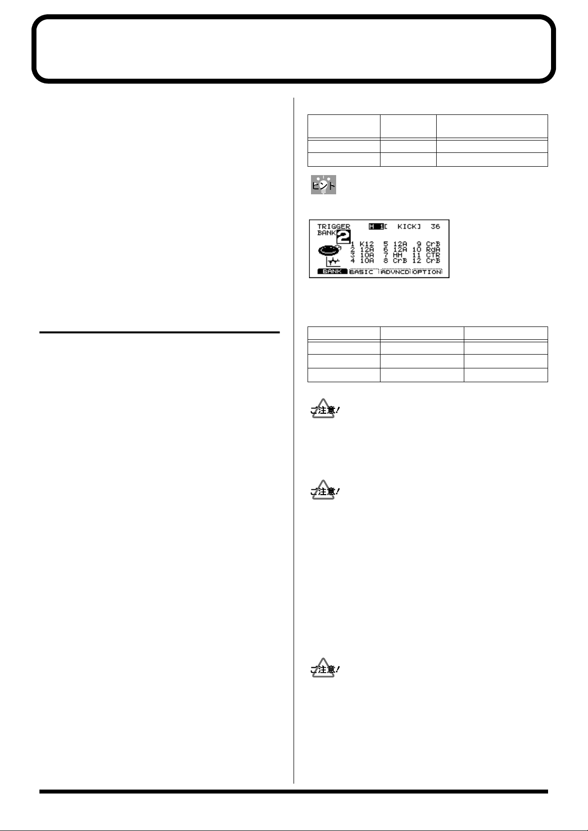
トリガー・バンクとトリガー・タイプ設定
初期状態のトリガー・バンクには、よく使われるキット構成
の設定があらかじめ用意されています。シンバルに PD-9 を
お使いの場合はバンク 1、V シンバルをお使いの場合はバン
ク 2 をご使用になると便利です。
トリガー・バンク 1
PD-9 をシンバルとして使用したキット用
トリガー・インプット トリガー・タイプ パッド
1/KICK K12 KD-120
2/SNARE 12A PD-120
3/TOM1 10A PD-100
4/TOM2 10A PD-100
5/TOM3 12A PD-120
6/TOM4 12A PD-120
7/HI-HAT P7B PD-7
8/CRASH1 P9B PD-9
9/CRASH2 P9B PD-9
10/RIDE P9A PD-9
11/AUX1 P9B PD-9
12/AUX2 P9B PD-9
トリガー・バンク 2
V シンバルを使用したキット用
CY-15R を 3 ウェイ・トリガー(
トリガー・インプット トリガー・タイプ パッド
1/KICK K12 KD-120
2/SNARE 12A PD-120
3/TOM1 10A PD-100
4/TOM2 10A PD-100
5/TOM3 12A PD-120
6/TOM4 12A PD-120
7/HI-HAT HH CY-12H
8/CRASH1 CrB CY-14C
9/CRASH2 CrB CY-14C
10/RIDE RdA CY-15R(BOW/BELL OUT)
11/AUX1 CTR CY-15R (BOW/EDGE OUT)
12/AUX2 CrB CY-14C
トリガー・バンク 3
V シンバルを使用したキット用
トリガー・バンク 4
打点位置検出を行わない設定
あらかじめプリセットされているトリガー・バンクの設定を
読み出す方法
1.
[SETUP]-[F1(TRIG)]を押してトリガー設定画面
を表示させます。
2.
[TOOLS]-[F1(COPY)]を押してトリガー・バン
ク・コピー画面を表示させます。
コピー元のプリセット・トリガー・バンクとコピー先の
3.
トリガー・バンクを選択し、[F4]を 2 回押してコピー
を実行します。
)として使用する場合
P.14
使用しているパッドが違う場合、トリガー・タイプを変更し
てください。
設定方法
[SETUP]-[F1(TRIG)]-[F1(BANK)]を押します。
詳しくは、TD-10 取扱説明書P.108の「パッドの種類を指
定する」をご覧ください。
バージョン・アップした TD-10 では、トリガー・タイプが
従来の 16 種類から 30 種類に拡張されています。
トリガー・タイプ一覧表
トリガー・
タイプ
12A PD-120 ○ ○
12B PD-120 ○
10A PD-100 ○
10B PD-100
8RA PD-80R ○ ○
8RB PD-80R ○
8 A PD-80 ○
8 B PD-80
P9A PD-9 ○ ○
P9B PD-9 ○
P7A PD-7 ○ ○
P7B PD-7 ○
PD5 PD-5
K12 KD-120
K80 KD-80
KD7 KD-7/KD-5
HH CY-12H ○
CrA CY-14C ○ ○
CrB CY-14C ○
RdA CY-15R ○ ○
RdB CY-15R ○
CTR CY-15R コントロール
P 1 汎用パッド1
P 2 汎用パッド2
K 1 汎用キック・パッド1
K 2 汎用キック・パッド2
KIK キック(ドラム・トリガー用)
SNR スネア(ドラム・トリガー用)
TOM タム・タム(ドラム・トリガー用)
FLR
(3 ウェイ・トリガー用)(P.14)
フロア・タム(ドラム・トリガー用)
「CTR」に設定したトリガー・インプットの音は、3 ウェ
イ・トリガーの用途以外では鳴らすことができません。
パッド リム
(エッジ)
打点位置
検出
11
Page 12
第 2章 トリガリングの改良について
弱打感度の改良
従来に比べてパッドからの微小な信号で安定して動作するよ
うになりました。弱い打撃信号を確実に受けることができま
す。
センシティビティーとスレッショルドのパラメーターの分解
能が従来の 16 段階から 32 段階に増え、より細かい設定が
できるようになりました。例えばオリジナル TD-10 のセン
シティビティーの 3 は、バージョン・アップした TD-10 の
6 に相当します。
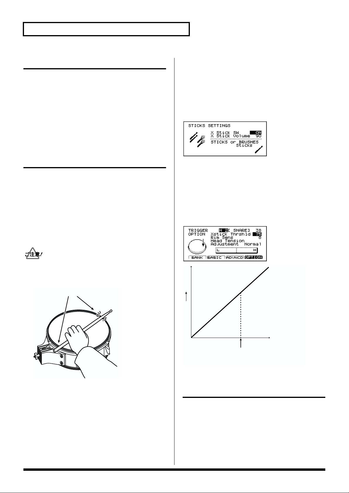
クロス・スティック奏法に対応
V-SNARE のインストを使用すると、クロス・スティックや
リム・ショットの音色を使用できます。
クロス・スティック奏法を行うときは、次の組み合わせが必
要です。
•
トリガー・インプット 2(SNARE)を使用している
•
トリガー・タイプが「12A」、「12B」、「8RA」、「8RB」
のいずれかである(P.11)
•
「X Stick SW」が「ON」に設定されている(次項)
クロス・スティック・ボリューム
スネアのクロス・スティック音の音量を、ドラム・キットご
とに調整します。
設定方法
[KIT]-[F2(FUNC)]-[F3(STICKS)]を押します。
設定範囲
X Stick Volume(Cross Stick Volume):0 〜 127
fig.CrossStickSettingScreen80
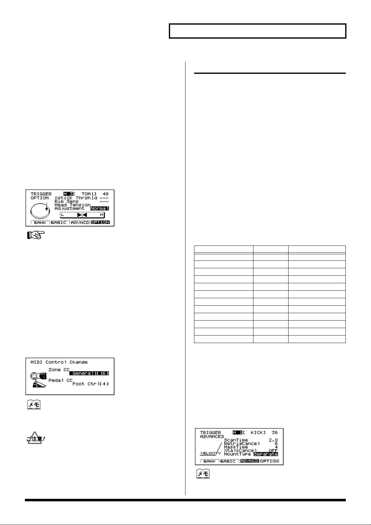
クロス・スティック・スレッショルド
クロス・スティック音とリム・ショット音が切り替わる強さ
を、トリガー・バンクごとに設定します。
設定方法
[SETUP]-[F1(TRIG)]-[F4(OPTION)]を押します。
設定範囲
Xstick Thrshld(Cross Stick Threshold):0 〜 127
fig.XstickThresholdScreen80
PD-120 や PD-80Rを使用してクロス・スティック奏法を
行うときは、パッドのリムのみを叩いてください。ヘッドの
上に手を置くと、正しく演奏することができません。
fig.CrossStick.j
リム部
次のパラメーターが追加されました。
クロス・スティック・スイッチ
クロス・スティック奏法のオン/オフを、ドラム・キットご
とに設定します。
設定方法
[KIT]-[F2(FUNC)]-[F3(STICKS)]を押します。
設定範囲
X Stick SW(Cross Stick Switch):OFF、ON
ig.CrossStickChart.j
大
音量
小
クロス・
スティック音
クロス・スティック・
スレッショルド
(0〜127)
リム・
ショット音
強い弱い
たたく強さ
(Velocity)
全てのトリガー・インプットで打 点位置検出に対応
パッドを叩く位置により、音色が変化します。
打点位置に対応して音色を変化させるときは、以下の組み合
わせが必要です。
•
トリガー・タイプが「**A」(打点位置を検出するもの)
である(P.11)
打点位置を受けて音色を変化させることができるインス
•
トを使用している(P.22)
12
Page 13
第 2章 トリガリングの改良について
ヘッドの貼り具合の調節
バージョン・アップした TD-10 では、すべてのトリガー・
インプットでヘッドの貼り具合の調節画面が表示されるよう
になりました。
メッシュ・ヘッドのパッド(PD-80、PD-80R、PD-100、
PD-120)を使用して打点位置に対応して音色変化をさせる
場合は、ヘッドの張り具合の調節が必要です。
調節するパッドのトリガー・タイプが「8 A」、「8RA」、
「10A」、「12A」のいずれかになっていることを確認してか
ら調節してください。
設定方法
[SETUP]-[F1(TRIG)]-[F4(OPTION)]を押します。
設定範囲
Head Tension Adjustment:Loose、Normal、Tight
fig.HeadAdjustScreen80
詳しい手順は、TD-10取扱説明書 P.31 の「ヘッドの貼り具
合を調節する」をご覧ください。
打点位置情報の設定
バージョン・アップした TD-10 では、スネア、ライド・シ
ンバルに加え、タムの打点位置情報が MIDI メッセージによ
り送受信できます。製品出荷時の設定では、打点位置情報の
送受信にコントロール・チェンジの 16 番を使用しています。
設定方法
[SETUP]-[F2(MIDI)]-[F2(CTRL)]を押します。
設定範囲
Zone CC:OFF、Modulation(1)、General1(16)、
General2(17)
fig.MIDIControlScreen80
打点位置情報を送信、および受信するコントロール・チェン
ジ番号は共通です。
クロストークによる誤発音を防止
次のパラメーターが変更、追加されています。
クロストーク・キャンセル
他のパッドを叩いた振動で、そのパッドが誤って発音してしまう
現象(クロストーク)を防ぎます。オリジナル TD-10 で
「Crosstalk」と呼んでいたものと動作は同じです。バージョン・
アップした TD-10 ではより細かく設定できるようになりました。
設定方法
[SETUP]-[F1(TRIG)]-[F3(ADVNCD)]を押します。
設定範囲
XtalkCancel
(Crosstalk Cancel):OFF、5 〜80(5ステップ刻み)
マウント・タイプ
パッドが取り付けられている状態を指定します。パッドをた
たいた時の振動が他のパッドに与える影響を TD-10 に知ら
せ、クロストークによる誤発音を防ぐことができます。
パッドの取り付けを変更したときに設定してください。
製品出荷時のトリガー・バンク 1 の設定
トリガー・インプット
1/KICK KD-120 Separate
2/SNARE PD-120 Separate
3/TOM1 PD-100 PadMount
4/TOM2 PD-100 PadMount
5/TOM3 PD-120 PadMount
6/TOM4 PD-120 PadMount
7/HI-HAT PD-7 CymMount
8/CRASH1 PD-9 CymMount
9/CRASH2 PD-9 CymMount
10/RIDE PD-9 CymMount
11/AUX1 PD-7 CymMount
12/AUX2 PD-7 CymMount
トリガー・インプット 2 に接続したスネアとして使用するパッ
ドをドラム・スタンドに直接取り付ける場合(例:MDS-8 の
スネアの位置に PD-80R を使用する場合)は、「MountType」
を「PadMount」に設定してください。スネアを叩いた振動で
他のパッドが鳴ってしまうことを防ぐことができます。
設定方法
[SETUP]-[F1(TRIG)]-[F3(ADVNCD)]を押します。
設定範囲
MountType:Separate、PadMount(Pad Mount)、
fig.CrosstalkSettingScreen80
CymMount(Cymbal Mount)
パッド マウント・タイプ
オリジナル TD-10 の演奏を録音した外部 MIDI 機器のデータを
バージョン・アップした TD-10 で利用するときは、打点位置情
報のコントロール・チェンジ番号を 16 番(バージョン・アッ
プした TD-10 の製品出荷時の設定)に変更してください。
(MIDIバルク・データやメモリー・カードに保存したデータは、
変更する必要はありません。)
ドラム・スタンドに直接固定しないパッドには、
「Separate」を選択します。
13
Page 14
第 3 章 V シンバルについて
ライド用 V シンバル CY-15R、クラッシュ用 V シンバル CY-14C、
ハイハット用 V シンバル CY-12H それぞれに対応したトリガー・
タイプに設定します(例えば、CY-12H は「HH」に設定します)。
※ 工場出荷時のトリガー・バンク 2 のトリガー・パ
ラメーターは Vシンバル用の設定になっています。
V シンバルはエッジ・ショットに対応していますので、エッ
ジ部を叩くと音源に設定されたリム側の音色を鳴らすことが
できます。また、音を鳴らしたあとに V シンバルのエッジ
を握るとチョーク奏法(音を止める奏法)が可能です。CY-
15R はボウ部の打点位置により音色が変化します。
V シンバルについての詳細は V シンバルの取扱説明書をご
覧ください。
ライド用 V シンバル CY-15R の接続と設定について
CY-15R には 2 つのアウトプット・ジャックがあり、用途
によって接続方法が変わります。
接続例
CY-15R
アウトプット
BOW/BELL 10/RIDE RdA(CY-15R)
BOW/EDGE 11/AUX1 CTR(CY-15Rコントロール )
TDW-1 初期状態のトリガー・バンク 2の設定です(P.11)。
fig.Bank2screen80
TD-10
TRIG INPUT
パッド・タイプ
奏法とトリガー・インプットの対応
奏法 トリガー・インプット 音色
ボウ・ショット 10/RIDE ヘッド ライドのボウ音色
ベル・ショット 10/RIDE リム ライドのベル音色
エッジ・ショット 11/AUX1 リム ライドのエッジ音色
ボウ・ショットとベル・ショットをす る場合
CY-15R の「BOW/BELL アウトプット」をTD-10の「ト
リガー・インプット 10/RIDE」に接続します。
10/RIDE のトリガー・タイプを「RdA」にします。
ベル部を叩くとリム側の音色を鳴らすことができます。
ボウ・ショットとエッジ・ショットを する場合
CY-15R の「BOW/EDGE アウトプット」を TD-10 の「ト
リガー・インプット 10/RIDE」に接続します。
10/RIDE のトリガー・タイプを「RdA」にします。
エッジ部を叩くとリム側の音色を鳴らすことができます。
ボウ・ショット/ベル・ショット/
エッジ・ショットをする場合
(3 ウェイ・トリガー)
CY-15R と TD-10 を 2 本のケーブルで接続することによ
り、ボウ/ベル/エッジの 3 つの音色を叩き分けて演奏す
ることができます(3 ウェイ・トリガー)。
CY-15R のアウトプットを次のように接続し、トリガー・タ
イプを設定します。
CY-15R を 1 本のケーブルで接続する場合は、トリガー・
タイプを「RdA(または RdB)」に設定してください。1 本
のケーブルで接続する場合にトリガー・タイプが「CTR」
に設定されていると、その音色は鳴りません。
トリガー・タイプ「CTR」を使用せずに 2本のケーブルで
CY-15R と TD-10 を接続すると、ボウ(またはエッジ)を
叩いたときにエッジとボウの音色が両方とも鳴ってしまいま
す。またトリガー・チェイスも正しく行えません。
トリガー・タイプが「CTR」に設定されると、音源の内部処理
により、「CTR」に設定されたトリガー・インプットに入力が
あったときに「RdA(または RdB)」に設定されたパッドの音
色を発音させないような制御が行われます。3 ウェイ・トリ
ガーとして使うためには、トリガー・タイプ「CTR」と
「RdA」を組で使用する必要があります。またトリガー・タイ
プ「CTR」は、CY-15R の 3 ウェイ・トリガー以外の用途で使
用することはありません。
3 ウェイ・トリガーとして使用できるのは 1つの CY-15R の
みです。「CTR」は 1 つのトリガー・インプットだけに設定
してください。そのとき RdA(または RdB)も 1 つだけに
設定してください。「CTR」を 2 つ以上のパッドに設定する
と、もっとも番号の小さいトリガー・インプット以外は「---」
と表示され「CTR」として動作しません(音も鳴りません)。
14
Page 15
第 4 章 追加機能について
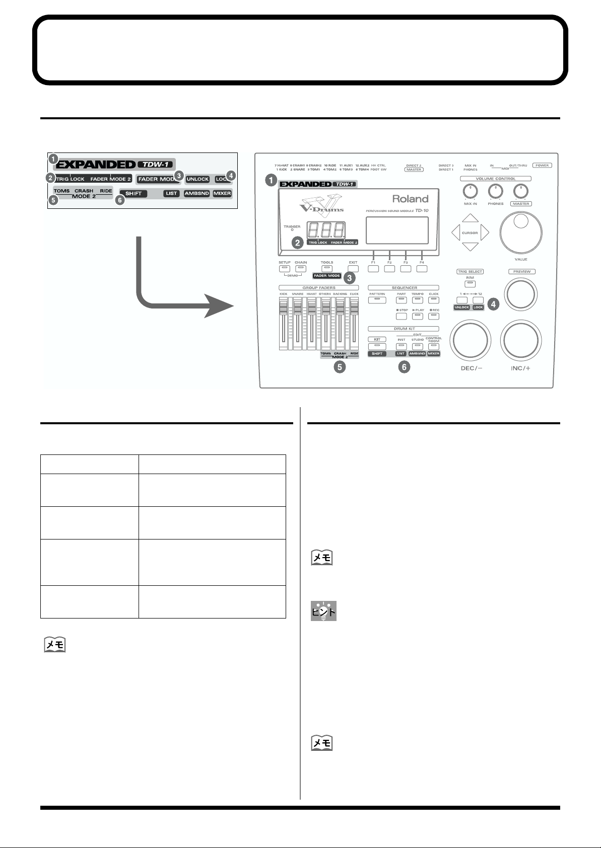
付属ラベルの貼りかた
追加された機能についてのステッカーが付属しています。次の図を参考に、TD-10に貼ってお使いください。
fig.TD10withLabel
各種ショートカット機能
次の画面へのショートカット機能が追加されました。
画面 操作
「INST LIST」画面 [SHIFT(KIT)]を押しながら
[LIST(INST)]を押す
「AMBIENCE SEND」画面[SHIFT(KIT)]を押しながら
[AMBSND(STUDIO)]を押す
「MIXER」画面 [SHIFT(KIT)]を押しながら
[MIXER(CONTROL ROOM)]
を押す
「TRIGGER BASIC」画面[SHIFT(KIT)]を押しながら
[SETUP]を押す
( )内は、TD-10本体にオレンジ色で印刷されているボタン
名です。
トリガー・チェイスのロック機能
インスト設定時に、あやまって他のパッドにふれてしまって
も、インストの設定画面が切り替わらないようにする機能で
す。
設定方法(トリガー・チェイス・ロック・
オン)
ロックしたいパッドを叩いた後、[SHIFT(KIT)]+[LOCK
(12)]を押します。
トリガー・チェイス・ロック・オンのときは、LED ディスプ
レイの一番左のドットが点灯します。
トリガー・チェイス・ロック・オンのときに[PREVIEW]を
押しながらパッドを叩くと、トリガー・チェイス・ロックを
一時的に解除し、ロックするパッドを変更することができま
す。
解除方法(トリガー・チェイス・ロック・
オフ)
[SHIFT(KIT)]+[UNLOCK(1)]を押します。
( )内は、TD-10本体にオレンジ色で印刷されているボタン
名です。
15
Page 16
第 4章 追加機能について
KIT 50
KIT 3
KIT 2
KIT 1
PAN OUTPUT
グループ・フェーダーの切り替え機能
[GROUP FADER]でタムとシンバルの音量を独立して調整
できるようになりました。フェーダー・モードを切り替える
と右側の 3 本のフェーダーの機能が切り替わります。
MODE 1
(オリジナル TD-10)
MODE 2
(新機能)
フェーダー・モードの切り替えかた
[SHIFT(KIT)]を押しながら[FADER MODE(TOOLS)]
を押します。
•
( )内は、TD-10 本体にオレンジ色で印刷されているボ
タン名です。
MODE 2 選択時は LEDディスプレイの一番右のドット
•
が点灯します。
フェーダー・モードを切り替えても、設定した音量バラ
•
ンスは保持されています。
MODE 2 で TOMS、CRASH、RIDE の音量バランスを
とった後に、MODE 1 に切り替えて OTHERS のフェー
ダーを動かすと、MODE 2 での音量バランスは失われ、
スライダーのつまみの位置の音量になります。
OTHERS BACKING CLICK
TOMS CRASH RIDE
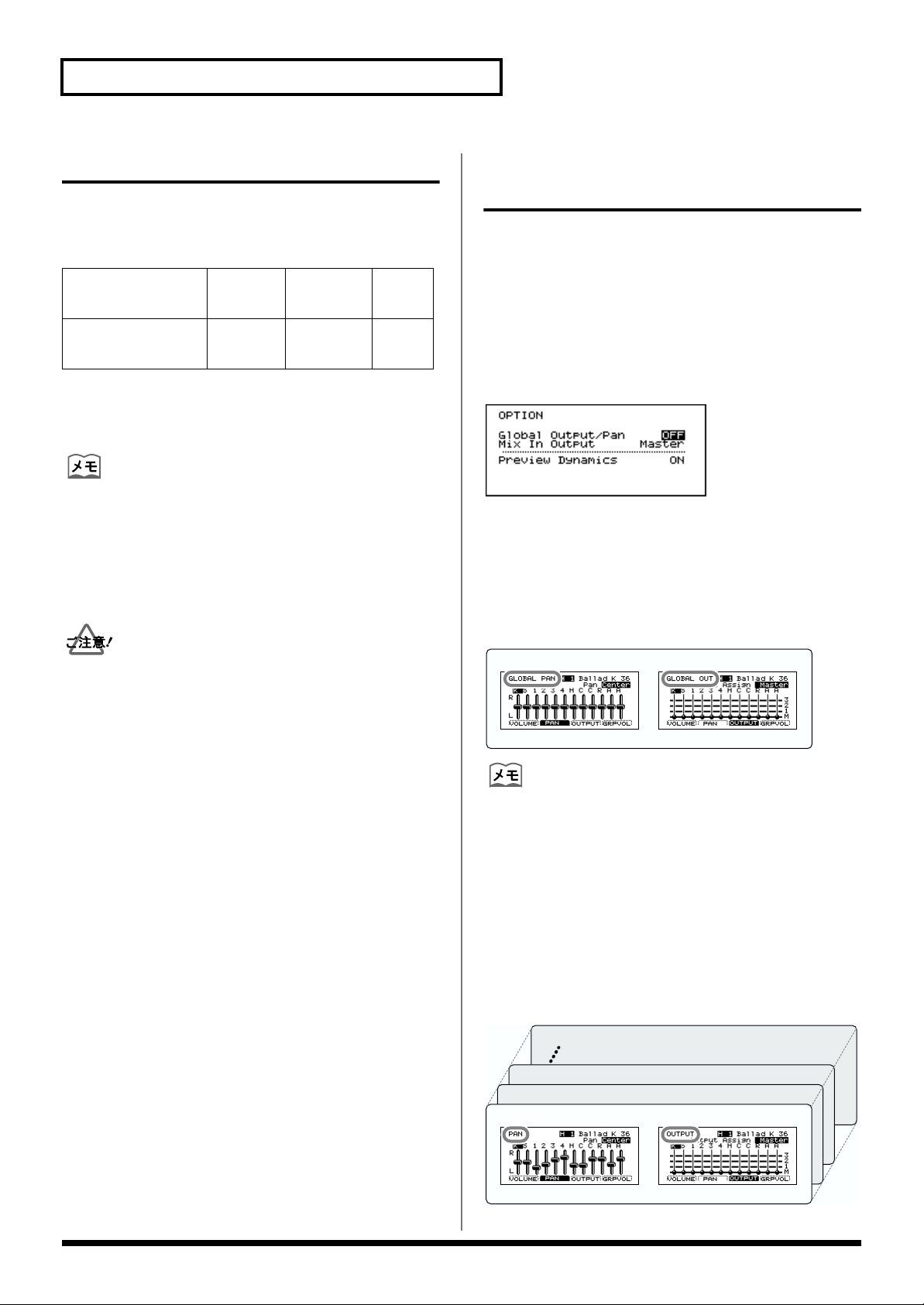
グローバル・アウトプット/パン の設定
ミキサーのアウトプット設定(アウトプットとパン)を全ド
ラム・キット共通で設定する機能が追加されました。「ON」
に設定すると、パンとアウトプットの設定時に、全キットに
共通の設定が呼び出されます。
設定方法
[SETUP]-[F3(CTRL)]-[F4(OPTION)]を押します。
設定範囲
Global Output/Pan:OFF、ON
ig.GlobalOutputScreen80
■
Global
全ドラム・キット共通のパンとアウトプットを設定します。
画面の左上に、「GLOBAL PAN」または「GLOBAL OUT」
と表示されます。
ffig.PAN.j
グローバル設定(全ドラム・キット共通)
GLOBAL PAN GLOBAL OUTPUT
Output/Pan=ON の場合
グローバル・アウトプット/パンを「ON」に設定している
間は、ドラム・キットごとに設定したパンとアウトプットの
設定は使われません。
■
Global Output/Pan=OFF の場合
現在選択しているドラム・キットのパンとアウトプットを設
定します。ドラム・キットごとに設定することができます。
画面の左上に、「PAN」または「OUTPUT」と表示されま
す。
ffig.PAN2.j
16
Page 17
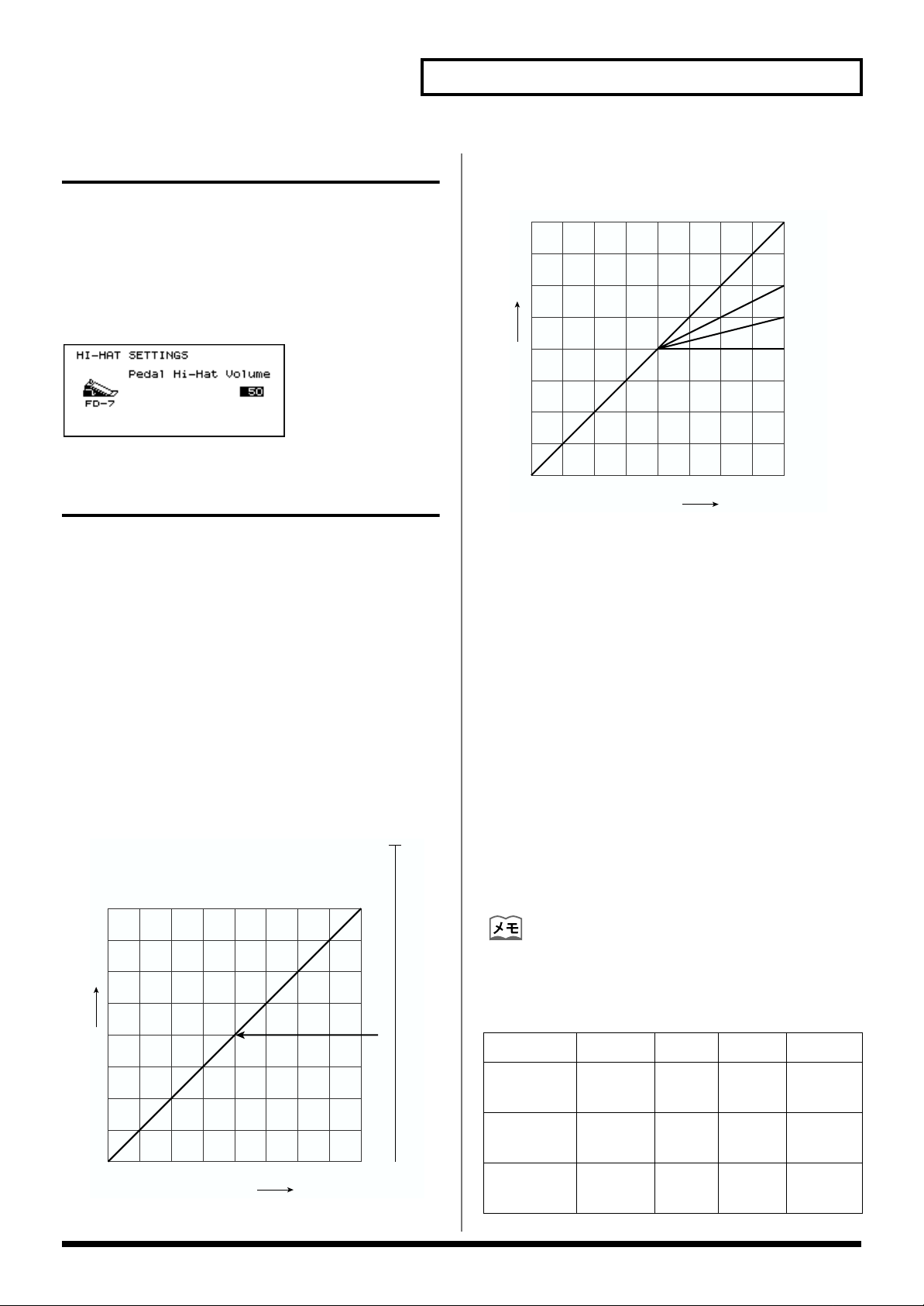
ペダル・ハイハットの音量調整
ドラム・キットごとにペダル・ハイハットの音量を設定する
ことができます。
設定方法
[KIT]-[F2(FUNC)]-[F2(HI-HAT)]
設定範囲
Pedal Hi-Hat Volume:0 〜 127
fig.Hi-HatVolumeScreen80
第 4章 追加機能について
「Ratio」を「2:1」〜「8:1」の値にし、出力の圧縮の程
4.
度を設定します。
fig.Compressor2.j
1:1
2:1
4:1
∞:1
音量
コンプレッサーの改良
コンプレッサーをより強く効かせる設定も可能になり、設定
値の効き具合が変更されました。
コンプレッサーの設定例
(音量の変化を減らして平均音量を上げる設定)
1.
FX SW で「AMBIENCE」を「OFF」、「COMP」を
「ON」にします。
2.
コンプレッサー設定画面で「Ratio」を「∞:1」、
「ATTACK」を「0.05(最小)」、「RELEASE」を「25」
にします。
3.
中位の強さでパッドを叩きながら「Threshold」を下げ
ていき、音量が下がり始める値に設定します。
(例:-30)
fig.Compressor1.j
スレッショルド
-10
弱 中 強
たたく強さ
「ATTACK Time」を延ばしていき、打楽器のアタック
5.
が聞こえるところまで延ばします。(例:1ms)
ATTACK Time(ATTACK)
スレッショルドを超えた入力があった時に、圧縮を開始
するまでの時間。
長い値に設定すると、コンプレッサーの効きが弱くなり
ます。
設定範囲:0.05 〜50ms
Release Time(RELEAS)
圧縮がかかっている状態から、入力がスレッショルドよ
り小さくなった時に、圧縮をやめるまでの時間。
長い値に設定すると、速い連打時に、後で叩いた音量が
小さくなります。
設定範囲:0.05 〜2000ms
0
6.
「OUTPUT」を設定します。
「COMP SW」を ON / OFF しながら最強打時の音量が
変わらないように設定します。
音量
弱 中 強
たたく強さ
-20
-30
-45
-60
バージョン・アップした TD-10 では、OUTPUTの設定
範囲が -48 〜 +24に変更されました。
代表的な設定例
Threshold Ratio ATTACK RELEASE
Limiter -10 〜 -20 ∞ :1 〜
8:1
Compressor -20 〜 -40 8:1 〜
2:1
音の加工 -40 〜 -60 4:1 〜
2:1
0.05 25
1.0 25
0.05 〜
10.0
25
17
Page 18
第 4章 追加機能について
インストのグループ選択
インストをグループ名から選択できるようになりました。
TDW-1で追加されたインストのグループ名には、「EXP」が
つきます。
「INST」画面
fig.SelectInstrumentScreen80
「Group」にカーソルを合わせて選択します。
ファンクション・キーの機能
[F3(IN EX)]:
「INST LIST」画面
fig.InstrumentListScreen80
[F1(GROUP )]と[F2(GROUP )]で選択します。
ファンクション・キーの機能
[F1(GROUP )]:インスト・グループを選択します。
TD-10 のインスト(IN)と TDW-1 の
インスト(EX)を切り替えます。
fig.PitchControlScreen80
ペダル・ハイハットが鳴らないようにするには、ペダル・ハ
イハットの音量を「0」に設定します(P.17)。
ピッチをなめらかに変化させるためには、[SETUP]-[F2
(MIDI)]-[F1(GLOBAL)]を押して、「Pedal Data Thin」
を「OFF」に変更してください。
パッド・パターン・ ベロシティー・スイッチ
パッド・パターン機能を使って演奏するとき、パッドを叩く
強さに応じて、パターン再生時のベロシティーを変化させる
ことができます。
設定方法
[INST]-[F4(CTRL )]-[F3(PATERN)]を押します。
設定範囲
Pad PTN Velo (Pad Pattern Velocity):OFF、ON
fig.PadPatternVelocity80
[F2(GROUP )]:インスト・グループを選択します。
[F3(IN EX)]:
ここで選択できるインスト・グループは、インスト・リスト
(P.22)をご覧ください。
TD-10 のインスト(IN)と TDW-1
のインスト(EX)を切り替えます。
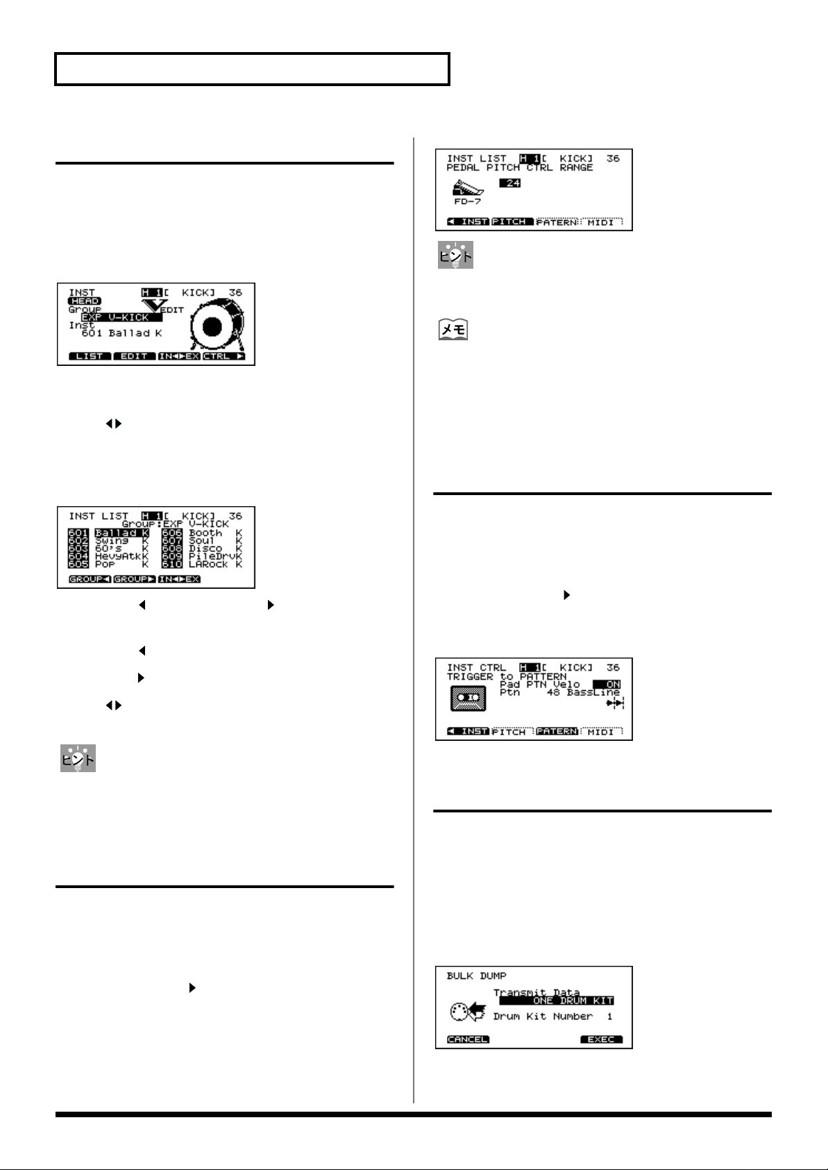
ハイハット・コントロール・ペダル を使ったピッチ・コントロール機能
ハイハット・コントロール・ペダル(FD-7)の踏み込み量
に応じてインストのピッチを変化させる設定です。
パッドごと(ヘッドとリムは独立)に半音単位で設定します。
設定方法
[INST]-[F4(CTRL )]-[F2(PITCH)]を押します。
設定範囲
PEDAL PITCH CTRL RANGE:-24 〜 0 〜24
ドラム・キットごとのバルク・ダンプ機能
それぞれのドラム・キットの設定を独立して保存できるよう
になりました。
設定方法
[SETUP]-[F2(MIDI)]-[F4(BULK)]を押して、
「Transmit Data」を「ONE DRUM KIT」に設定します。次
に、ドラム・キットの番号を選択して、[F4(EXEC)]を押
してください。
fig.BulkDumpScreen80
18
Page 19
第 4章 追加機能について
ハイハット・ノート・ナンバー・ボーダー
TD-10 とパッドの演奏を外部音源で鳴らすときに送信される
MIDI メッセージの設定です。TD-10 とパッドだけで演奏/
録音するときは、設定を変更する必要はありません。(製品
出荷時は「127」に設定されています。)
TD-10のハイハットのパッドを叩いたときに送信される
ノート・ナンバーは、ハイハット・ペダルの踏み込み位置に
よって切り替わります。
ハイハット・ノート・ナンバー・ボーダーは、オープン・ハ
イハットからクローズ・ハイハットにノート・ナンバーが切
り替わるペダル位置を変更することができます。
製品出荷時の値(127)では、ペダルを完全に踏み込んだ状
態でハイハットのパットが叩かれたときのみ、クローズ・ハ
イハットのノート・ナンバーを送信します。
ペダルを踏み込んだ位置から少し上でもクローズ・ハイハッ
トのノート・ナンバーを送信させたいときは、値を 90 など
に設定してください。
ハイハット・ノート・ナンバー・ボーダーの設定を変更する
と、パッドの演奏を内蔵シーケンサーに録音したときに、実
際の演奏と録音したパターンのハイハットの動作が異なるこ
とがあります。
設定方法
[SETUP]-[F2(MIDI)]-[F1(GLOBAL)]を押します。
設定範囲
HH Note# Border:0 〜 127
fig.HHBorderScreen80
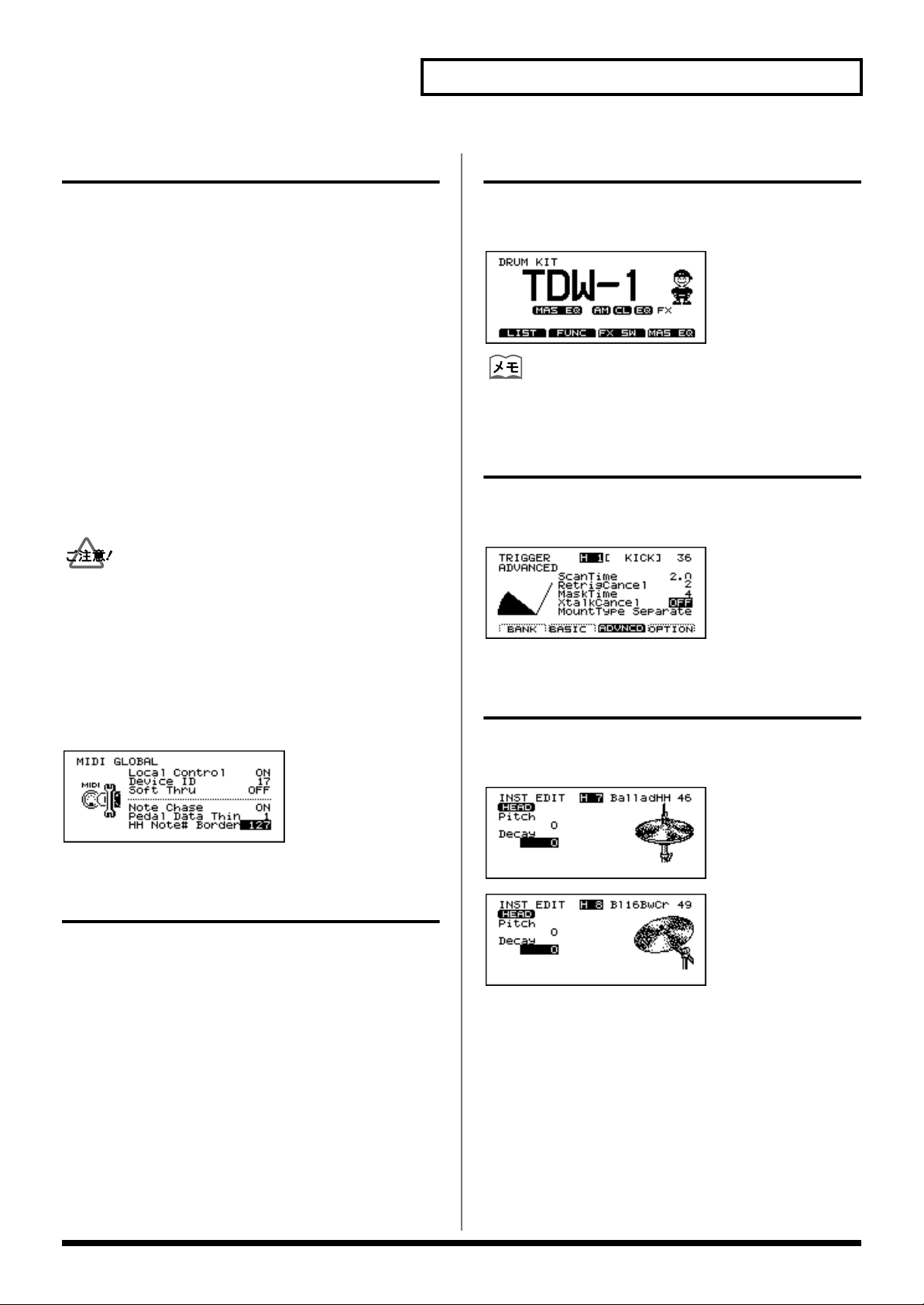
「DRUM KIT」画面のマスター EQ 表示
マスター EQ をON にすると、「DRUM KIT」画面に「MAS
EQ」のアイコンが表示されます。
fig.kitMasEQScreen
マスター EQ をOFFにしたときは、アイコンが消えます。
「TRIGGER ADVANCED」画面の
ベロシティー・メーター
「TRIGGER ADVANCED」画面にベロシティー・メーターが
追加されました。
fig.TrigAdvScreen2
シンバル・エディット画面のアイコン
シンバル・エディット画面に表示されるアイコンが変更され
ました。
fig.CymEditScreen1
fig.CymEditScreen2
クリック(メトロノーム)用音色の追加
クリック用の音色が 4 つ追加されました。
設定方法
[CLICK]-[F2(INST)]を押します。
音色
+
Voice、Click、Beep
Block、Sticks
Conga、Talking Drum、Maracas、Cabasa、Cuica
Agogo、Tambourine、Snaps、909 Snare、808 Cowbell
+
:TDW-1で新しく追加された音色
、Metronome+、Claves、Wood
+
、Cross Stick+、Triangle、Cowbell、
19
Page 20

第 5 章 応用使用例
パッドとアコースティック・ドラ ム間のクロストーク回避法
fig.PadsAcousticPads
アコースティックのスネア・ドラムを叩いたときに、近くに
セッティングしている V-Drums のパッドの音が鳴る場合、
スネア・ドラムにドラム・トリガーを取り付け、クロストー
クを回避することができます。
スネア・ドラムにドラム・トリガーを取り付けます。
1.
fig.SnareWithTrigger.e
それでも音が鳴る場合、「Threshold」の値を上げます。
6.
「Threshold」の設定方法について詳しくは、TD-10取扱説
明書 P.109 をご覧ください。
タップ・パターンの録音から演奏まで
パッド・パターン機能を使って、パッドを叩くたびに録音し
たパターンの音を順に再生することができます。さらに、
パッド・パターン・ベロシティー機能を設定すると、パッド
を叩いた強さに応じてパターンの音量を変化させることがで
きます。
1.
タップ再生に使用するパターンを録音します。
タップ再生に使用するパターンをリアルタイム・レコー
ディングするときは、レコーディングの前にクォンタイ
ズの設定をしてください(TD-10 取扱説明書P.103)。
クォンタイズの設定をしないと、正しくタップ再生でき
ません。
パターンの録音方法について詳しくは、TD-10 取扱説
明書 P.101 をご覧ください。
ワイヤーが触れないようにしてください
2.
ドラム・トリガーをトリガー・インプット端子の1つに
接続します。(例:AUX1)
3.
ドラム・トリガーを接続したトリガー・インプットのト
リガー・タイプを「SNR」に、マウント・タイプを
「CymMount」に設定します。
4.
スネア・ドラムを叩いたときに、TD-10 の音を鳴らした
くない場合は、ドラム・トリガーを接続したトリガー・
インプットのインストを「600 OFF」または「960
EXP OFF」に設定します。
[CONTROL ROOM]-[MIXER]で音量を「0」に設定
することもできます。
スネアを叩いたときに鳴ってしまうパッドの
5.
「Crosstalk Cancel」の値を上げます(P.13)。
•
バッキング・インストを録音するときは、MIDI キーボー
ドが必要です。
タップ再生には、メロディー・ラインやベース・ライ
•
ン、コードのどちらのパターンも使用できます。
録音したパターンの再生のしかたを設定します。
2.
•
[PATTERN]-[F2 (FUNC)]-[F3 (TYPE)]を押
します。
「Play Type」を「TAP」にします。
•
3.
[INST]-[F4(CTRL )]-[F3 (PATERN)]を押
•
•
•
複数のパッドに異なるパターンを割り当てた場合、あるパ
ターンを再生中に別のパッドを叩くと、パターンを切り替え
て再生することができます。
ただし、インストの設定が異なるパターンに切り替わるとき
は、一瞬音がとぎれることがあります。
パッド・パターン機能とパッド・パターン・ベロシ
ティー機能の設定をします。
します。
パッド・パターン・ベロシティー・スイッチを設定しま
す(P.18)。
再生するパターンを選択します。
20
Page 21

第 5章 応用使用例
クリック(メトロノーム)音のみを 外部 MIDI 機器と同期させる方法
クリック音のみを外部 MIDI 機器と同期させることができま
す(この設定では、シーケンサーは同期しません)。
1.
TD-10のMIDI IN端子と外部シーケンサーのMIDI OUT端
子を MIDI ケーブルで接続します。
2.
[PATTERN]- [F2 (FUNC)]- [F1 (GLOBAL)]
を押します。
「Sync Mode」を「MIDI → Delay」に設定します。
3.
4.
[KIT]を押します。
[CLICK]を押します(TD-10 取扱説明書 P.129)。
5.
リム・ショットについて
PD-120 と PD-80Rのリム・ショットは、トリガー・イン
プット 2(SNARE)に接続したときのみ可能です。
PD-7/9
リム・ショット
1/KICK ○ ×
2/SNARE ○ ○
PD-120/PD-80R
リム・ショット
各種コピーの一覧表
各画面で、パラメーターの設定値のみをコピーすることがで
きます。
次の画面を表示しているときに、[TOOLS]-[F1
(COPY)]を押すと、コピー画面になります。
画面 コピーする内容 コピー先
「DRUM KIT」
「PERC
GROUP」
「INST」 インストの設定 他のドラム・
「STUDIO」 スタジオの設定 ドラム・キット
「CONTROL
ROOM」
「MIXER」 ミキサーの設定 ドラム・キット
「COMP」 コンプレッサーの設
ドラム・キットの設定
パーカッション・グ
ループの設定
コントロール・ルー
ムの設定
定(トリガー・イン
プット 1 〜 10 すべ
て)
ドラム・キット
パーカッション・
グループ
キットの同じ
トリガー・
インプット
ドラム・キット
ドラム・キット
3/TOM1 ○ ×
4/TOM2 ○ ×
5/TOM3 ○ ×
6/TOM4 ○ ×
7/HI-HAT ○ ×
8/CRASH1 ○ ×
9/CRASH2 ○ ×
10/RIDE ○ ×
11/AUX1 ○ ×
12/AUX2 ○ ×
PCS-31(別売のケーブル)を使用しても、1 つのトリガー・
インプットに 2 つのパッドをつなぐことはできません。
「EQ」 イコライザーの設定
(トリガー・インプッ
ト 1 〜 10 すべて)
「EFFECT」 エフェクトの設定 ドラム・キット
「TRIGGER
BANK」
オリジナル TD-10 のメモリー・カードのデータはコピー、
エクスチェンジできません。「LOAD ALL」のみが可能です。
トリガー・バンクの設定トリガー・
ドラム・キット
バンク
21
Page 22

第 6 章 資料編
インスト・リスト
No. Name 備考
EXP V-KICK
601
Ballad K
Swing K
602
60's K
603
HevyAtkK
604
605
Pop K
606
Booth K
Soul K
607
Disco K
608
PileDrvK
609
610
LARock K
611
Custom K
Oldies K
612
Beech K
613
Ebony K
614
615
MahognyK
616
AcrylicK
LoBoostK
617
Solid3 K
618
Dry 2 K
619
620
Buzz 1 K
621
Buzz 2 K
Amb 1 K
622
Amb 2 K
623
Wood 4 K
624
625
MdVrb2 K
626
Ninja K
Boomy K
627
EXP KICK
628
ThinHedK
629
StandrdK
Power K
630
Jazz 3 K
631
632
ElBend K
633
ElBend2K
634
Elec 2 K
Plastk1K
635
Plastk2K
636
637
Plastk3K
638
Gabba K
639
Gabba2 K
Tail K
640
Jungle K
641
642
HipHop K
643
LoFi K
EXP V-SNARE
644
Ballad2S *p *x
Bld2RimS *x
645
Swing S *p *x
646
SwngRimS *x
647
648
60's S *p *x
649
60'sRimS *x
Heavy S *p *x
650
HevyRimS *x
651
Pop S *p *x
652
653
Pop RimS *x
654
Studio S *p *x
StdoRimS *x
655
Custom S *p *x
656
CstmRimS *x
657
658
Dirty S *p *x
659
DrtyRimS *x
12" S *p *x
660
12" RimS *x
661
Birch S *x
662
663
BrchRimS *x
664
Booth S *p *x
BothRimS *x
665
EXP SNARE
666
Snappy S
667
SnpyRimS
Brush3 S *b
668
MIDIBr3S
669
670
Bronze2S
671
Brz2RimS
672
10" S
Stndrd1S
673
Stndrd2S
674
675
Stndrd3S
676
Jazz 2 S
677
FatBladS
DncClapS
678
ElecPwrS
679
680
ElcPwr2S
681
Real808S
682
Real909S
ElBend2S
683
Elec 2 S
684
685
HipHop2S
686
LoFi S
687
LoFiRimS
Radio S
688
CrsStk 7
689
690
CrsStk 8
691
CrsStk 9
692
CrsStk10
CrsStk11
693
CrsStk12
694
695
CrsStk13
EXP V-TOM
696
BalladT1 *p
BalladT2 *p
697
BalladT3 *p
698
BalladT4 *p
699
700
Swing T1 *p
701
Swing T2 *p
Swing T3 *p
702
Swing T4 *p
703
60's T1 *p
704
705
60's T2 *p
706
60's T3 *p
60's T4 *p
707
Heavy T1 *p
708
Heavy T2 *p
709
710
Heavy T3 *p
711
Heavy T4 *p
Pop T1 *p
712
Pop T2 *p
713
Pop T3 *p
714
715
Pop T4 *p
716
OldiesT1 *p
OldiesT2 *p
717
OldiesT3 *p
718
OldiesT4 *p
719
720
MahgnyT1 *p
721
MahgnyT2 *p
MahgnyT3 *p
722
MahgnyT4 *p
723
Stage T1 *p
724
725
Stage T2 *p
726
Stage T3 *p
Stage T4 *p
727
OysterT1 *p
728
OysterT2 *p
729
730
OysterT3 *p
731
OysterT4 *p
Comp T1 *p
732
Comp T2 *p
733
Comp T3 *p
734
735
Comp T4 *p
736
Dry2 T1 *p
Dry2 T2 *p
737
Dry2 T3 *p
738
Dry2 T4 *p
739
740
Rose T1 *p
741
Rose T2 *p
Rose T3 *p
742
Rose T4 *p
743
Jazz2 T1 *p
744
745
Jazz2 T2 *p
746
Jazz2 T3 *p
Jazz2 T4 *p
747
Balsa T1 *p
748
Balsa T2 *p
749
750
Balsa T3 *p
751
Balsa T4 *p
EXP TOM
752
StndrdT1
StndrdT2
753
StndrdT3
754
StndrdT4
755
756
ElcPwrT1
757
ElcPwrT2
ElcPwrT3
758
ElcPwrT4
759
ElBendT1
760
761
ElBendT2
762
ElBendT3
ElBendT4
763
ElBnd2T1
764
ElBnd2T2
765
766
ElBnd2T3
767
ElBnd2T4
ElDualT1
768
ElDualT2
769
ElDualT3
770
771
ElDualT4
772
Elec2 T1
Elec2 T2
773
Elec2 T3
774
Elec2 T4
775
EXP HI-HAT
BalladHH
776
Bld EgHH
777
778
Swing HH
779
SwngEgHH
780
60's HH
60'sEgHH
781
Heavy2HH
782
783
Hvy2EgHH
784
GroovyHH
785
GrvyEgHH
PureEgHH
786
BritEgHH
787
788
JazzEgHH
789
ThinEgHH
790
Pop EgHH
HevyEgHH
791
DarkEgHH
792
793
LiteEgHH
794
12" EgHH
795
13" EgHH
14" EgHH
796
15" EgHH
797
798
TechnoHH
799
Voice HH
*p
:打点位置による音色変化が得られます(P.12)。
*x
:
クロス・スティック奏法が可能です。クロス・スティックの音を鳴らす必要が無い場合はクロス・スティック・スイッチをオフにしてください(
*b
:ブラシ・スウィープ奏法(ヘッドをブラシでこする奏法)が可能です。
ハイハットのエッジ音色について
TDW-1 ではハイハットのエッジ音色(ハイハットのエッジを叩いたときの音色)が追加されています。ハイハット用のパッドのリム側に
エッジ音色を割り当ててご使用ください。
HH
:ハイハット音色
EgHH
:エッジ用ハイハット音色
※ TD-10 に搭載されていたハイハット音色に対応するエッジ音が追加されています。例えば、316: Pure HH に対応するエッ
ジ音色は 786: PureEgHH となっています。
22
P.12)。
Page 23

第 6章 資料編
No. Name 備考
EXP CRASH
800
Blad18Cr
801
Bl18BwCr
802
Bl18EgCr
Blad16Cr
803
Bl16BwCr
804
805
Bl16EgCr
806
Hard16Cr
807
Hd16BwCr
Hd16EgCr
808
Hard14Cr
809
810
Hd14BwCr
811
Hd14EgCr
812
Swng18Cr
Sw18EgCr
813
Swng16Cr
814
815
Sw16EgCr
816
LAJz Cr
817
LAJzEgCr
Paper Cr
818
PaprEgCr
819
820
Thin16Cr
821
Thin18Cr
822
MalletCr
Splsh 6"
823
Cup 6"
824
825
HdSpl10"
826
FsnSplsh
827
BldSplsh
RokChina
828
JazChina
829
830
FsnChina
831
MinChina
832
PgyCrsh7
PgyCrsh8
833
PgChina1
834
835
PgChina2
836
PgChina3
837
Elec Cr
TR808 Cr
838
EXP RIDE
839
BaladRd *p
840
BaladRdB
841
BaladRdX *p
SwingRd *p
842
SwingRdB
843
844
SwingRdE
845
SwingRdX *p
846
LAJazRd *p
LAJazRdB
847
LAJazRdX *p
848
849
HeavyRd *p
850
HeavyRdB
851
Fusn Rd *p
Fusn RdB
852
PrgJzRd
853
854
PrgJzRdE
855
JzSzlRd *p
856
JzSzlRdB
RkSzlRd *p
857
RkSzlRdB
858
859
CrashRd *p
860
CrashRdE
861
Crash2Rd
Flat1 Rd *p
862
Flat2 Rd *p
863
864
Jazz RdE
865
Pop RdE
866
Rock RdE
Lite RdE
867
MalletRd
868
EXP PERC
Bongo2Hi
869
Bongo2Lo
870
Conga2Mt
871
872
Conga2Sl
873
Conga2Op
Conga2Lo
874
CngMt VS
875
CngSl VS
876
877
Tmbl3 Hi
878
Tmbl3 Rm
Tmbl3 Lo
879
Paila
880
881
PotDrmOp
882
PotDrmMt
883
PotDrmAc
PotDrmUp
884
TrkDrmOp
885
886
TrkDrmUp
887
ThaiGong
888
Wa-Daiko
TreeChim
889
CncrtBD2
890
891
ConBD Mt
892
TimpaniG
893
TimpaniC
PercHit2
894
Orch Maj
895
896 Orch Min
897
Orch Dim
898
Kick/Rol
Kick/Cym
899
Hit Roll
900
901 Finale
EXP OTHER
909Clap
902
Clap
903
904
Bendor
905
Thunder
906
Bomb
Beep
907
MetroBel
908
909
MetroClk
910
Sticks
911
Tamb FX
Tek Clik
912
Random
913
914
DynScrch
915
Phil Hit
916
LoFi Hit
ChoVoice
917
Atmspher
918
919
Ring FX
920
JungleCr
Laser
921
Tekno FX
922
923
Bend Up
924
TeknoBrd
925
Scrape
Nantoka!
926
TeknoHit
927
928
FunkHit1
929
FunkHit2
930
FunkHit3
Vocoder1
931
Vocoder2
932
933
OhYear!
934
Hooh!
935
Voice K
Voice S
936
Voice T1
937
938 Voice T2
939
Voice T3
940
Voice T4
Voice Cr
941
EXP FIXED HI-HAT
942
Pure CH
943
Pure ECH
Pure OH
944
Jazz CH
945
946
Jazz ECH
947
Jazz OH
948
Thin CH
Thin ECH
949
Thin OH
950
951
Hevy CH
952
Hevy ECH
953
Hevy OH
BalladCH
954
BaladECH
955
956
BalladOH
957
Swing CH
958
SwingECH
Swing OH
959
EXP OFF
960
EXP OFF
クラッシュ・シンバル音色について
クラッシュ・シンバルにはいくつかのタイプが用意されている音色があります。
Cr
:オーソドックスな音色変化のあるクラッシュ音色
BwCr
:シンバルのボウを叩いたときの音色
EgCr
:シンバルのエッジを叩いた時の音色
※ パッドのヘッド部に
ライド・シンバル音色について
ライド・シンバルにはいくつかのタイプが用意されています。
Rd
:ボウを叩いた時のオーソドックスなライド音色
RdB
:カップを叩いた時のベル音色
RdX
:弱打時はボウの音色、強打時はベル音色
RdE
:シンバルのエッジを叩いた時の音色
※ パッドのヘッド部に Rd、リム部に
フィクスド・ハイハット音色 について
インストグループのフィクスド・ハイハット (Fixed Hi-Hat) は、ハイハット・シンバルが固定されたハイハット用の音色としてお使い
ください。これらの音色ではハイハット・コントロール・ペダルの制御が効きません。
:クローズド・ハイハット
CH
:エッジを叩いたクローズド・ハイハット
ECH
:
ハーフオープン・ハイハット
OH
※ ディケイの設定でハイハットの開き具合を調節できます。
BwCr
、リム部に
EgCr
を割り当てるとボウとエッジ音色の叩き分けが可能です。
を割り当てるとボウとベル音色の叩き分けが可能です。
RdB
23
Page 24

第 6章 資料編
ドラム・キット・リスト
TDW-1 プリセット・ドラム・キット
TDW-1で新規に追加されたドラム・キットです。バージョン・アップ後は、これら 50個のドラム・キットがユーザー・エ
リアに読み込まれます(P.7)。
NO. キット名 備考
1
2
3
4
5
6
7
8
9
10
11
12
13
14
15
16
17
18
19
20
21
22
23
24
25
TDW-1 *x
FunkSeq *x *seq
Ballad *x
Pop *x
NeoJazz *x
Rocker *x
60'sRock *x
Phase!
Egad *x
Brushes2 *b
Caliente *seq
Techno
TimpBend *pitch
JHThang *x
GateKepr *x
Buzzz.. *x
Break>it
ToP *x
Voices
Backbeat *x
Realdeal *x
HipBop *x
Custom *x
Loopy
Stage! *x
NO. キット名 備考
26
27
28
29
30
31
32
33
34
35
36
37
38
39
40
41
42
43
44
45
46
47
48
49
50
5thElmnt
Edgey
Pot Drum *pitch
Studio *x
UndrWatr
TechBoy
Nashkit *x
NoRain *x
BendMe *pitch
BackSlap *x
Mallet
RoseWood *x
Birch *x
LatnFevr
Spooked *pitch
DrumsJr. *x
BTO
BeBopDlx *x
Dr.Delay *x
ThinHead *x
ShrtStop
Found *pitch
Drum'nBs *tap
BgBndSeq *x *tap
5/4 Funk *x *seq
*x
: クロス・スティック奏法が可能です。クロス・スティックの音を鳴らす必要がない場合はクロス・スティック・スイッチをオフに
してください (P.12)。
*b
: ブラシ・スウィープ奏法(ヘッドをブラシでこする奏法)が可能です。
*pitch
:ハイハット・コントロール・ペダルによって特定のパッドのピッチがコントロールされます(P.18)。
*seq
: Crash2 のリムなどを叩くとパターンが再生されます。
*tap
: タップ・パターンが設定されています。
TD-10 の プリセット・ドラム・キット 5 つを変更し新規のドラム・キットを搭載
46 ProgJazz *x *seq
NoSnare *x
Theater *x *seq
Take 1 *x *seq
DenkiTom *seq
オリジナル TD-10 のドラム・キットを使うときは、コピー機能で呼び出してください(P.7)。
24
47
48
49
50
Page 25

第 6章 資料編
パーカッション・グループ
fig.percussion
パーカッション・グループ1
C1
C2
C3
C4
C5
C6
Note No.
23
24
26
28
29
31
33
35
36
38
40
41
43
45
47
48
50
52
53
55
57
59
60
62
64
65
67
69
71
72
74
76
77
79
81
83
84
86
88
89
91
93
*
インスト
22
600 OFF
529 Ou!
544 WahGtDw1
545 WahGtUp1
25
600 OFF
516 Hi-Q
27
517 MtlNoise
546 WahGtDw2
547 WahGtUp2
30
600 OFF
600 OFF
32
600 OFF
34
600 OFF
600 OFF
600 OFF
689 CrsStk 7 *
37
600 OFF
600 OFF
39
600 OFF
600 OFF
600 OFF
42
600 OFF
44
600 OFF
600 OFF
46
600 OFF
600 OFF
600 OFF
600 OFF
49
600 OFF
600 OFF
51
600 OFF
600 OFF
409 Tambrn 1
54
600 OFF
56
407 Cowbell2 *
600 OFF
58
600 OFF
379 Pop RdX
869 Bongo2Hi *
870 Bongo2Lo *
61
871 Conga2Mt *
63
873 Conga2Op *
874 Conga2Lo *
878 Tmbl3 Rm *
879 Tmbl3 Lo *
66
446 Agogo H
68
447 Agogo L
435 CabasUp
70
432 Maracas
445 WhislSht
444 WhislLng
449 GuiroSht
73
448 GiroLng1
75
434 Claves
463 WdBlockH
464 WdBlockL
78
451 CuicaMt1
452 CuicaOpn
80
462 TringlMt
461 TringlOp
82
433 Shaker
465 Sleibell
476 BellTree
460 Castanet
85
442 SurdoLMt
87
443 SurdoLOp
880 Paila *
872 Conga2Sl *
90
889 TreeChim *
882 PotDrmMt *
92
881 PotDrmOp *
883 PotDrmAc *
:オリジナル TD-10 から変更されたインスト
※ 他のパーカッション・セットは変更されていません。
ドラム・キット
トリガー・インプット
7/HI-HAT Rim (close)
7/HI-HAT Rim (open)
11/AUX1
11/AUX1 Rim
12/AUX2
12/AUX2 Rim
1/KICK Rim
1/KICK
2/SNARE
6/TOM4 Rim
2/SNARE Rim
6/TOM4
7/HI-HAT (close)
5/TOM3
7/HI-HAT (pedal)
4/TOM2
7/HI-HAT (Open)
4/TOM2 Rim
3/TOM1
8/CRASH1
3/TOM1 Rim
10/RIDE
9/CRASH2 Rim
10/RIDE Rim
8/CRASH1 Rim
9/CRASH2
5/TOM3 Rim
プリセット・パターン・リスト
No. パターン名 テンポ 小節数 再生タイプ 備考
1
Drums 124 8 Loop *
2
GroovPop 132 4 Loop *
Pop Rock 132 4 Loop *
3
Big Rock 82 4 Loop *
4
Funk 1 174 4 Loop *
5
6
Funk 2 196 4 Loop *
7
16bt'Rok 112 4 Loop
16bt'Bld 75 4 Loop
8
CntryRok 106 12 Loop
9
Blues 55 8 Loop
10
11
JazCombo 180 8 Loop *
12
Big Band 140 4 Loop
JazWaltz 160 4 Loop
13
UK Acid 86 4 Loop
14
Gang Rap 90 4 Loop
15
16
T Groove 100 4 Loop
17
Funky 105 4 Loop
JazzFunk 125 4 Loop
18
S.Soul 154 4 Loop
19
Pop Shfl 114 8 Loop
20
21
Fusion 120 12 Loop
22
Tech Fsn 106 4 Loop
Funk 7/8 100 4 Loop *
23
N.J.S. 107 4 Loop
24
House 113 4 Loop
25
26
HipHop 144 4 Loop *
27
Techno 140 4 Loop
28
Jungle 170 4 Loop
Latin 125 8 Loop
29
Bossa 74 8 Loop
30
31
Songo 109 4 Loop
32
Samba 110 2 Loop
33
Salsa 108 4 Loop
Raggae 132 8 Loop
34
Ska 132 4 Loop
35
36
PercLoop 130 2 Loop *
37
Funk5/4A 86 2 Loop *
38
Funk4/4B 86 4 Loop *
Cowbell 120 1 Loop *
39
Dbl Bass 130 1 1Shot *
40
41
DrumFill 240 2 1Shot
42
Syn Bass 120 4 Tap *
43
EP Chord 120 1 Tap *
StrChord 150 8 Tap *
44
Aco Bass 160 4 Tap *
45
46
Brs Sect 160 5 Tap *
47
Chord 120 2 Tap
48
BassLine 120 1 Tap
Perc Tap 120 8 Tap
49
AdlbSolo 120 11 Tap *
50
:オリジナルTD-10 から変更され新規に搭載されたパターン
*
25
Page 26

第 6章 資料編
メッセージ
次のメッセージが追加されました。
Old TD-10 Data!!
Some parameters cannot be loaded
このメモリー・カードのデータは、バージョン・アップ
していないオリジナル TD-10 で保存されたものです。
トリガーとコンプレッサーの設定は読み込まれません。
Once this data is saved it can't be used with a nonexpanded TD-10
バージョン・アップした TD-10 のデータをこのメモ
リー・カードに保存すると、バージョン・アップしてい
ないオリジナル TD-10 で使用できなくなります。
CHECK TDW-1 BOARD
Turn POWER OFF and re-install it
TDW-1が抜き取られているか、正しく取り付けられて
いません。TD-10の電源を切って、TDW-1 を取り付け
なおしてください。
26
Page 27

MIDI インプリメンテーション
パラメータ・アドレス・マップ
(Model ID = 00H 2DH)
このマップは、エクスクルーシブ・メッセージの「データ・セット1」によりデータ転送を
行う際の、アドレス、サイズ、データの設定できる範囲、パラメーター(データの種類)、
説明を記述したものです。
アドレス、サイズ、データの記述は全て 16 進表示、説明の欄は 10 進表記です。
「#」の付いているアドレスは先頭アドレスとして使用できません。
「(*TDW)」の付いているアドレスは、TD-10 (Model ID = 00H 0AH) と互換性がありません。
■ Parameter Address Block
TDW-1 (Model ID = 00H2DH)
+———————————————————————————————————————————————————————————————————————+
| Start | |
| address | Description |
|—————————————+—————————————————————————————————————————————————————————|
| 00 00 00 00 | SETUP (Individual) *1-1|
|—————————————+—————————————————————————————————————————————————————————|
| 01 00 00 00 | DRUM KIT 1 (Individual) *1-2|
| : | |
| 01 31 00 00 | DRUM KIT 50 (Individual) *1-2|
|—————————————+—————————————————————————————————————————————————————————|
| 04 00 00 00 | PERCUSSION GROUP 1 (Individual) *1-3|
| : | |
| 04 03 00 00 | PERCUSSION GROUP 4 (Individual) *1-3|
|—————————————+—————————————————————————————————————————————————————————|
| 10 00 00 00 | PATTERN (Bulk) *1-4|
|—————————————+—————————————————————————————————————————————————————————|
| 40 00 00 00 | SETUP (Bulk) *1-1|
|—————————————+—————————————————————————————————————————————————————————|
| 41 00 00 00 | DRUM KIT 1 (Bulk) *1-2|
| : | |
| 41 31 00 00 | DRUM KIT 50 (Bulk) *1-2|
|—————————————+—————————————————————————————————————————————————————————|
| 44 00 00 00 | PERCUSSION GROUP 1 (Bulk) *1-3|
| : | |
| 44 03 00 00 | PERCUSSION GROUP 4 (Bulk) *1-3|
+———————————————————————————————————————————————————————————————————————+
* 1-1 SETUP
+———————————————————————————————————————————————————————————————————————+
| Offset | |
| address | Description |
|—————————————+—————————————————————————————————————————————————————————|
| 00 00 00 | TRIGGER BANK 1 *1-1-1|
| : | |
| 00 30 00 | TRIGGER BANK 4 *1-1-1|
|—————————————+—————————————————————————————————————————————————————————|
| 01 00 00 | DRUM KIT CHAIN 1 (Name) *1-1-2|
| : | : |
| 01 0F 00 | DRUM KIT CHAIN 16 (Name) *1-1-2|
|—————————————+—————————————————————————————————————————————————————————|
| 02 00 00 | DRUM KIT CHAIN 1 (Step) *1-1-3|
| : | : |
| 02 0F 00 | DRUM KIT CHAIN 16 (Step) *1-1-3|
|—————————————+—————————————————————————————————————————————————————————|
| 03 00 00 | MIDI *1-1-4|
|—————————————+—————————————————————————————————————————————————————————|
| 04 00 00 | PROGRAM CHANGE MAP *1-1-5|
|—————————————+—————————————————————————————————————————————————————————|
| 05 00 00 | CONTROL *1-1-6|
|—————————————+—————————————————————————————————————————————————————————|
| 06 00 00 | MASTER EQ *1-1-7|
|—————————————+—————————————————————————————————————————————————————————|
| 07 00 00 | MASTER TUNE *1-1-8|
|—————————————+—————————————————————————————————————————————————————————|
| 08 00 00 | GLOBAL OUT/PAN *1-1-9|
+———————————————————————————————————————————————————————————————————————+
* 1-1-1 TRIGGER BANK
+———————————————————————————————————————————————————————————————————————+
| Offset | |
| address | Description |
|—————————————+—————————————————————————————————————————————————————————|
| 00 00 | Pad parameters (1/KICK) *1-1-1-1|
| : | : |
| 0B 00 | Pad parameters (12/AUX2) *1-1-1-1|
+———————————————————————————————————————————————————————————————————————+
* 1-1-1-1 TRIGGER BANK (Pad parameters)
+———————————————————————————————————————————————————————————————————————+
| Offset | |
| address | Description |
|—————————————+—————————————————————————————————————————————————————————|
| 00 | 000a aaaa | Trigger Type 0 - 29 (*TDW)|
| | | (12A,12B,10A,10B,8RA,8RB,8A,8B, |
| | | P9A,P9B,P7A,P7B,PD5,K12,K80,KD7, |
| | | HH,CrA,CrB,RdA,RdB,CTR, |
| | | P1,P2,K1,K2,KIK,SNR,TOM,FLR) |
|—————————————+———————————+—————————————————————————————————————————————|
| 01 | 0000 0aaa | Sens Curve 0 - 7 (*TDW)|
| | | (Linear,EXP1,EXP2,LOG1,LOG2,Spline, |
| | | Loud1,Loud2) |
|—————————————+———————————+—————————————————————————————————————————————|
| 02 | 000a aaaa | Crosstalk Cancel 0 - 16 (*TDW)|
| | | (OFF,5,10,15,20,25,30,35,40,45,50, |
| | | 55,60,65,70,75,80) |
|—————————————+———————————+—————————————————————————————————————————————|
| 03 | 0000 00aa | Mount Type 0 - 2 (*TDW)|
| | | (Separate,PadMount,CymMount) |
|—————————————+———————————+—————————————————————————————————————————————|
| 04 | 0000 aaaa | Rim Sensitivity 0 - 15 (*TDW)|
| | | (OFF, 1 - 15) |
第 6章 資料編
| | | (2/SNARE only) |
|—————————————+———————————+—————————————————————————————————————————————|
| 05 | 0aaa aaaa | Xstick Threshold 0 - 127 (*TDW)|
| | | (2/SNARE only) |
|—————————————+———————————+—————————————————————————————————————————————|
| 06 | 0000 00aa | Head Tension Adjustment 0 - 2 (*TDW)|
| | | (Loose,Normal,Tight) |
| | | (2/SNARE only) |
|—————————————+———————————+—————————————————————————————————————————————|
| 07 | 000a aaaa | STICK | Sensitivity 0 - 31 (*TDW)|
| | | | (1 - 32) |
| 08 | 000a aaaa | STICK | Threshold 0 - 31 (*TDW)|
| 09 | 00aa aaaa | STICK | Scan Time 0 - 40 (*TDW)|
| | | | (0.0ms - 4.0ms, 0.1ms step) |
| 0A | 0000 aaaa | STICK | Retrigger Cancel 0 - 15 (*TDW)|
| | | | (1 - 16) |
| 0B | 000a aaaa | STICK | Mask Time 0 - 16 (*TDW)|
| | | | (0ms - 64ms, 4ms step) |
|—————————————+———————————+—————————————————————————————————————————————|
| 0C | 000a aaaa | BRUSH | Sensitivity 0 - 31 (*TDW)|
| | | | (1 - 32) |
| 0D | 000a aaaa | BRUSH | Threshold 0 - 31 (*TDW)|
| | | | (0.0ms - 4.0ms, 0.1ms step) |
| 0E | 00aa aaaa | BRUSH | Scan Time 0 - 40 (*TDW)|
| 0F | 0000 aaaa | BRUSH | Retrigger Cancel 0 - 15 (*TDW)|
| | | | (1 - 16) |
| 10 | 000a aaaa | BRUSH | Mask Time 0 - 16 (*TDW)|
| | | | (0ms - 64ms, 4ms step) |
|—————————————+—————————————————————————————————————————————————————————|
| Total size | 00 00 00 11 |
+———————————————————————————————————————————————————————————————————————+
* 1-1-2 DRUM KIT CHAIN (Name)
+———————————————————————————————————————————————————————————————————————+
| Offset | |
| address | Description |
|—————————————+—————————————————————————————————————————————————————————|
| 00 | 0aaa aaaa | Drum Kit CHAIN Name 32 - 127 |
|# 01 | 0aaa aaaa | Drum Kit CHAIN Name 32 - 127 |
| : | : | |
|# 07 | 0aaa aaaa | Drum Kit CHAIN Name 32 - 127 |
|—————————————+—————————————————————————————————————————————————————————|
| Total size | 00 00 00 08 |
+———————————————————————————————————————————————————————————————————————+
* 1-1-3 DRUM KIT CHAIN (Step)
+———————————————————————————————————————————————————————————————————————+
| Offset | |
| address | Description |
|—————————————+—————————————————————————————————————————————————————————|
| 00 | 0aaa aaaa | Drum Kit Number (Step1) 0 - 50 |
| | | (1-50, END) |
|# 01 | 0aaa aaaa | Drum Kit Number (Step2) 0 - 50 |
| | | (1-50, END) |
| : | : | |
|# 1F | 0aaa aaaa | Drum Kit Number (Step32) 0 - 50 |
| | | (1-50, END) |
|—————————————+—————————————————————————————————————————————————————————|
| Total size | 00 00 00 20 |
+———————————————————————————————————————————————————————————————————————+
* 1-1-4 MIDI
+———————————————————————————————————————————————————————————————————————+
| Offset | |
| address | Description |
|—————————————+—————————————————————————————————————————————————————————|
| 00 00 | 000a aaaa | MIDI Channel (DRUM) 0 - 16 |
| | | (1 - 16,OFF) |
| 00 01 | 000a aaaa | MIDI Channel (PART1) 0 - 16 |
| | | (1 - 16,OFF) |
| 00 02 | 000a aaaa | MIDI Channel (PART2) 0 - 16 |
| | | (1 - 16,OFF) |
| 00 03 | 000a aaaa | MIDI Channel (BASS) 0 - 16 |
| | | (1 - 16,OFF) |
|—————————————+———————————+—————————————————————————————————————————————|
| 00 04 | 0000 00aa | Zone CC 0 - 3 |
| | | (OFF,Modulation(1),General1(16), |
| | | GENERAL2(17)) |
| 00 05 | 0aaa aaaa | HH Note# Border 0 - 127 (*TDW)|
| 00 06 | 0000 0aaa | Pedal CC 0 - 4 |
| | | (OFF,Modulation(1),Foot Ctrl(4), |
| | | General1(16),General2(17)) |
|—————————————+———————————+—————————————————————————————————————————————|
| 00 07 | 0000 000a | Program Change Rx SW 0 - 1 |
| | | (OFF,ON) |
| 00 08 | 0000 000a | Program Change Tx SW 0 - 1 |
| | | (OFF,ON) |
|—————————————+———————————+—————————————————————————————————————————————|
| 00 09 | 0000 000a | Local Control 0 - 1 |
| | | (OFF,ON) |
| 00 0A | 0000 000a | Soft Through 0 - 1 |
| | | (OFF,ON) |
| 00 0B | 0000 000a | Note Chase 0 - 1 |
| | | (OFF,ON) |
| 00 0C | 0000 00aa | Pedal Data Thin 0 - 2 |
| | | (OFF,1,2) |
|—————————————+—————————————————————————————————————————————————————————|
| Total size | 00 00 00 0D |
+———————————————————————————————————————————————————————————————————————+
* 1-1-5 PROGRAM CHANGE MAP
+———————————————————————————————————————————————————————————————————————+
| Offset | |
| address | Description |
|—————————————+—————————————————————————————————————————————————————————|
| 00 00 | 0aaa aaaa | Program Change (DRUM KIT 1) 0 - 127 |
| | | (1 - 128) |
| : | | |
| 00 31 | 0aaa aaaa | Program Change (DRUM KIT 50) 0 - 127 |
| | | (1 - 128) |
|—————————————+———————————+—————————————————————————————————————————————|
| Total size | 00 00 00 32 |
+———————————————————————————————————————————————————————————————————————+
27
Page 28

第 6章 資料編
* 1-1-6 CONTROL
+———————————————————————————————————————————————————————————————————————+
| Offset | |
| address | Description |
|—————————————+—————————————————————————————————————————————————————————|
| 00 00 | 0000 00aa | Foot SW Mode 0 - 2 (*1) |
| 00 01 | 0000 0aaa | Pad SW Mode 0 - 4 (*2) |
| 00 02 | 0000 aaaa | Display Contrast 0 - 15 |
| | | (1 - 16) |
| 00 03 | 0000 000a | Mix In Output 0 - 1 |
| | | (Master,Phones Only) |
| 00 04 | 0000 000a | Preview Dynamics 0 - 1 |
| | | (OFF,ON) |
| 00 05 | 0aaa aaaa | Preview Velocity 1 - 127 |
|—————————————+—————————————————————————————————————————————————————————|
| Total size | 00 00 00 06 |
+———————————————————————————————————————————————————————————————————————+
(*1) Foot SW Mode
0 KIT SELECT KIT# DEC KIT#INC
1 PATTERN SEL PTN# DEC PTN#INC
2 PATTERN PLAY PTN#INC STOP/PLAY
(*2) Pad SW Mode
0 OFF OFF OFF
1 KIT SELECT OFF KIT#INC
2 PATTERN SEL OFF PTN# INC
3 KIT SELECT(2) KIT# DEC KIT#INC
4 PATTERN SEL(2) PTN#DEC PTN# INC
[SW1] [SW2]
[ AUX1 ] [ AUX2 ]
* 1-1-7 MASTER EQ
+———————————————————————————————————————————————————————————————————————+
| Offset | |
| address | Description |
|—————————————+—————————————————————————————————————————————————————————|
| 00 00 | 0000 aaaa | Low Frequency 0 - 14 |
| | | (20Hz - 500Hz) |
| 00 01 | 0aaa aaaa | Low Gain 49 - 79 |
| | | (-15db - +15db) |
|—————————————+———————————+—————————————————————————————————————————————|
| 00 02 | 000a aaaa | Mid Frequency 7 - 23 |
| | | (100Hz - 4kHz) |
| 00 03 | 0aaa aaaa | Mid Gain 49 - 79 |
| | | (-15db - +15db) |
| 00 04 | 000a aaaa | Mid Q 0 - 20 |
| | | (0.5,1.0 - 20.0, 1.0step) |
|—————————————+———————————+—————————————————————————————————————————————|
| 00 05 | 000a aaaa | High Frequency 14 - 30 |
| | | (500Hz - 20kHz) |
| 00 06 | 0aaa aaaa | High Gain 49 - 79 |
| | | (-15db - +15db) |
|—————————————+———————————+—————————————————————————————————————————————|
| 00 07 | 0000 000a | SW 0 - 1 |
| | | (OFF,ON) |
|—————————————+—————————————————————————————————————————————————————————|
| Total size | 00 00 00 08 |
+———————————————————————————————————————————————————————————————————————+
* 1-1-8 MASTER TUNE
+———————————————————————————————————————————————————————————————————————+
| Offset | |
| address | Description |
|—————————————+—————————————————————————————————————————————————————————|
| 00 00 | 0000 aaaa | Master Tune 0 - 509 |
|# 01 | 0000 bbbb | (415.3 - 466.2Hz) |
|# 02 | 0000 cccc | |
|# 03 | 0000 dddd | |
|—————————————+—————————————————————————————————————————————————————————|
| Total size | 00 00 00 04 |
+———————————————————————————————————————————————————————————————————————+
* 1-1-9 GLOBAL OUT/PAN
+———————————————————————————————————————————————————————————————————————+
| Offset | |
| address | Description |
|—————————————+—————————————————————————————————————————————————————————|
| 00 00 | 0000 000a | SW 0 - 1 (*TDW)|
| | | (OFF,ON) |
|—————————————+—————————————————————————————————————————————————————————|
| 00 01 | 000a aaaa | Pan Kick 0 - 30 (*TDW)|
| | | (L15 - R15) |
| 00 02 | 000a aaaa | Pan Snare 0 - 30 (*TDW)|
| | | (L15 - R15) |
| 00 03 | 000a aaaa | Pan Tom1 0 - 30 (*TDW)|
| | | (L15 - R15) |
| 00 04 | 000a aaaa | Pan Tom2 0 - 30 (*TDW)|
| | | (L15 - R15) |
| 00 05 | 000a aaaa | Pan Tom3 0 - 30 (*TDW)|
| | | (L15 - R15) |
| 00 06 | 000a aaaa | Pan Tom4 0 - 30 (*TDW)|
| | | (L15 - R15) |
| 00 07 | 000a aaaa | Pan Hihat 0 - 30 (*TDW)|
| | | (L15 - R15) |
| 00 08 | 000a aaaa | Pan Crash1 0 - 30 (*TDW)|
| | | (L15 - R15) |
| 00 09 | 000a aaaa | Pan Crash2 0 - 30 (*TDW)|
| | | (L15 - R15) |
| 00 0A | 000a aaaa | Pan Ride 0 - 30 (*TDW)|
| | | (L15 - R15) |
| 00 0B | 000a aaaa | Pan Aux1 0 - 30 (*TDW)|
| | | (L15 - R15) |
| 00 0C | 000a aaaa | Pan Aux2 0 - 30 (*TDW)|
| | | (L15 - R15) |
|—————————————+—————————————————————————————————————————————————————————|
| 00 0D | 0000 00aa | Output Assign Kick 0 - 3 (*TDW)|
| | | (MASTER,DIR1,DIR2,DIR3) |
| 00 0E | 0000 00aa | Output Assign Snare 0 - 3 (*TDW)|
| | | (MASTER,DIR1,DIR2,DIR3) |
| 00 0F | 0000 00aa | Output Assign Tom1 0 - 3 (*TDW)|
| | | (MASTER,DIR1,DIR2,DIR3) |
| 00 10 | 0000 00aa | Output Assign Tom2 0 - 3 (*TDW)|
| | | (MASTER,DIR1,DIR2,DIR3) |
| 00 11 | 0000 00aa | Output Assign Tom3 0 - 3 (*TDW)|
| | | (MASTER,DIR1,DIR2,DIR3) |
| 00 12 | 0000 00aa | Output Assign Tom4 0 - 3 (*TDW)|
| | | (MASTER,DIR1,DIR2,DIR3) |
| 00 13 | 0000 00aa | Output Assign Hihat 0 - 3 (*TDW)|
| | | (MASTER,DIR1,DIR2,DIR3) |
| 00 14 | 0000 00aa | Output Assign Crash1 0 - 3 (*TDW)|
| | | (MASTER,DIR1,DIR2,DIR3) |
| 00 15 | 0000 00aa | Output Assign Crash2 0 - 3 (*TDW)|
| | | (MASTER,DIR1,DIR2,DIR3) |
| 00 16 | 0000 00aa | Output Assign Ride 0 - 3 (*TDW)|
| | | (MASTER,DIR1,DIR2,DIR3) |
| 00 17 | 0000 00aa | Output Assign Aux1 0 - 3 (*TDW)|
| | | (MASTER,DIR1,DIR2,DIR3) |
| 00 18 | 0000 00aa | Output Assign Aux2 0 - 3 (*TDW)|
| | | (MASTER,DIR1,DIR2,DIR3) |
|—————————————+—————————————————————————————————————————————————————————|
| Total size | 00 00 00 19 |
+———————————————————————————————————————————————————————————————————————+
* 1-2 DRUM KIT
+———————————————————————————————————————————————————————————————————————+
| Offset | |
| address | Description |
|—————————————+—————————————————————————————————————————————————————————|
| 00 00 | Common parameters *1-2-1|
| 01 00 | Pad parameters (1/KICK) *1-2-2|
| 02 00 | Pad parameters (2/SNARE) *1-2-2|
| 03 00 | Pad parameters (3/TOM1) *1-2-2|
| 04 00 | Pad parameters (4/TOM2) *1-2-2|
| 05 00 | Pad parameters (5/TOM3) *1-2-2|
| 06 00 | Pad parameters (6/TOM4) *1-2-2|
| 07 00 | Pad parameters (7/HIHAT) *1-2-2|
| 08 00 | Pad parameters (8/CRASH1) *1-2-2|
| 09 00 | Pad parameters (9/CRASH2) *1-2-2|
| 0A 00 | Pad parameters (10/RIDE) *1-2-2|
| 0B 00 | Pad parameters (11/AUX1) *1-2-2|
| 0C 00 | Pad parameters (12/AUX2) *1-2-2|
+———————————————————————————————————————————————————————————————————————+
* 1-2-1 DRUM KIT (Common parameters)
+———————————————————————————————————————————————————————————————————————+
| Offset | |
| address | Description |
|—————————————+—————————————————————————————————————————————————————————|
| 00 00 00 | 0aaa aaaa | Drum Kit Name 1 32 - 127 |
|# 00 00 01 | 0aaa aaaa | Drum Kit Name 2 32 - 127 |
| : | | |
|# 00 00 07 | 0aaa aaaa | Drum Kit Name 8 32 - 127 |
|—————————————+—————————————————————————————————————————————————————————|
| 00 00 08 | 0000 00aa | PERCUSSION GROUP Assign 0 - 3 |
| | | (1 - 4 ) |
+———————————————————————————————————————————————————————————————————————+
| 00 00 09 | 0000 0000 | dummy (ingnored) |
|—————————————+———————————+—————————————————————————————————————————————|
| 00 00 0A | 0aaa aaaa | GROUP VOLUME (DRUMS) 0 - 127 |
| 00 00 0B | 0aaa aaaa | GROUP VOLUME (PERC) 0 - 127 |
|—————————————+———————————+—————————————————————————————————————————————|
| 00 00 0C | 0aaa aaaa | AMBIENCE Group Send Level (DRUMS) 0 - 127 |
| 00 00 0D | 0aaa aaaa | AMBIENCE Group Send Level (PERC) 0 - 127 |
| 00 00 0E | 0aaa aaaa | AMBIENCE Group Send Level (PART) 0 - 127 |
|—————————————+———————————+—————————————————————————————————————————————|
| 00 00 0F | 0aaa aaaa | EFFECT Group Send Level (DRUMS) 0 - 127 |
| 00 00 10 | 0aaa aaaa | EFFECT Group Send Level (PERC) 0 - 127 |
| 00 00 11 | 0aaa aaaa | EFFECT Group Send Level (PART) 0 - 127 |
|—————————————+———————————+—————————————————————————————————————————————|
| 00 00 12 | 0aaa aaaa | AMBIENCE Output Level (MASTER) 0 - 127 |
| 00 00 13 | 0aaa aaaa | AMBIENCE Output Level (DIR1) 0 - 127 |
| 00 00 14 | 0aaa aaaa | AMBIENCE Output Level (DIR2) 0 - 127 |
| 00 00 15 | 0aaa aaaa | AMBIENCE Output Level (DIR3) 0 - 127 |
|—————————————+———————————+—————————————————————————————————————————————|
| 00 00 16 | 0aaa aaaa | EFFECT Output Level 0 - 127 |
|—————————————+———————————+—————————————————————————————————————————————|
| 00 00 17 | 0000 000a | AMBIENCE SW 0 - 1 |
| | | (OFF,ON) |
| 00 00 18 | 0000 000a | EFFECT SW 0 - 1 |
| | | (OFF,ON) |
| 00 00 19 | 0000 000a | COMP SW 0 - 1 |
| | | (OFF,ON) |
| 00 00 1A | 0000 000a | EQ SW 0 - 1 |
| | | (OFF,ON) |
|—————————————+———————————+—————————————————————————————————————————————|
| 00 00 1B | 0000 aaaa | AMBIENCE Type 0 - 9 |
| | | (Beach, Living Room, Bath Room, |
| | | Studio, Garage, Locker Room, |
| | | Theater, Cave, Gymnasium, |
| | | Dome Stadium) |
| 00 00 1C | 0000 0aaa | AMBIENCE Room Size 0 - 4 |
| | | (Tiny, Small, Medium, Large, Huge) |
| 00 00 1D | 0000 00aa | AMBIENCE Wall Type 0 - 2 |
| | | (Wood, Plaster, Glass) |
| 00 00 1E | 0000 000a | AMBIENCE Mic Position 0 - 1 |
| | | (Low, High) |
|—————————————+———————————+—————————————————————————————————————————————|
| 00 00 1F | 000a aaaa | EFFECT Type 0 - 29 |
| 00 00 20 | 0aaa aaaa | EFFECT Param 1 0 - 127 |
| 00 00 21 | 0aaa aaaa | EFFECT Param 2 0 - 127 |
| 00 00 22 | 0aaa aaaa | EFFECT Param 3 0 - 127 |
| 00 00 23 | 0aaa aaaa | EFFECT Param 4 0 - 127 |
|—————————————+———————————+—————————————————————————————————————————————|
| 00 00 24 | 0000 000a | Stick Type 0 - 1 |
| | | (Sticks, Brushes) |
|—————————————+———————————+—————————————————————————————————————————————|
| 00 00 25 | 0000 aaaa | Pedal HH Volume Adjust -127 - +127 (*TDW)|
|# 26 | 0000 bbbb | |
|—————————————+———————————+—————————————————————————————————————————————|
| 00 00 27 | 0000 000a | X Stick SW 0 - 1 (*TDW)|
| | | (OFF,ON) |
|—————————————+———————————+—————————————————————————————————————————————|
28
Page 29

第 6章 資料編
| 00 00 28 | 0000 aaaa | X Stick Volume Adjust -127 - +127 (*TDW)|
|# 29 | 0000 bbbb | |
|—————————————+———————————+—————————————————————————————————————————————|
| Total size | 00 00 00 2A |
+———————————————————————————————————————————————————————————————————————+
* 1-2-2 DRUM KIT (Padparameters)
+———————————————————————————————————————————————————————————————————————+
| Offset | |
| address | Description |
|—————————————+—————————————————————————————————————————————————————————|
| 00 | 0000 aaaa | HEAD | Instrument 0 - 959 |
|# 01 | 0000 bbbb | | (1 - 960) |
|# 02 | 0000 cccc | | |
|# 03 | 0000 dddd | | |
|—————————————+———————————+——————+——————————————————————————————————————|
| 04 | 0000 aaaa | HEAD | Pitch (Head Tuning) -480 - +480 |
|# 05 | 0000 bbbb | | (-4800 - 4800cent, 10cent step) |
|# 06 | 0000 cccc | | |
|# 07 | 0000 dddd | | |
|—————————————+———————————+——————+——————————————————————————————————————|
| 08 | 0aaa aaaa | HEAD | Decay 33 - 95 |
| | | | (-31 - +31) |
| 09 | 0aaa aaaa | HEAD | Level 0 - 127 |
| 0A | 0aaa aaaa | HEAD | Note number 0 - 127 |
| 0B | 0aaa aaaa | HEAD | Ambience Send Level 0 - 127 |
| 0C | 0aaa aaaa | HEAD | Effect Send Level 0 - 127 |
| 0D | 0aaa aaaa | HEAD | Play Pattern number 0 - 100 |
| | | | (OFF,1 - 100) |
| 0E | 0aaa aaaa | HEAD | MIDI Gate Time 1 - 80 |
| | | | (0.1s - 8.0s, 0.1s step) |
|—————————————+———————————+——————+——————————————————————————————————————|
| 0F | 0000 aaaa | RIM | Instrument 0 - 959 |
|# 10 | 0000 bbbb | | (1 - 960) |
|# 11 | 0000 cccc | | |
|# 12 | 0000 dddd | | |
|—————————————+———————————+——————+——————————————————————————————————————|
| 13 | 0000 aaaa | RIM | Pitch (Head Tuning) -480 - 480 |
|# 14 | 0000 bbbb | | (-4800 - +4800cent, 10cent step) |
|# 15 | 0000 cccc | | |
|# 16 | 0000 dddd | | |
|—————————————+———————————+——————+——————————————————————————————————————|
| 17 | 0aaa aaaa | RIM | Decay 33 - 95 |
| | | | (-31 - +31) |
| 18 | 0aaa aaaa | RIM | Level 0 - 127 |
| 19 | 0aaa aaaa | RIM | Note number 0 - 127 |
| 1A | 0aaa aaaa | RIM | Ambience Send Level 0 - 127 |
| 1B | 0aaa aaaa | RIM | Effect Send Level 0 - 127 |
| 1C | 0aaa aaaa | RIM | Play Pattern number 0 - 100 |
| | | | (OFF,1 - 100) |
| 1D | 0aaa aaaa | RIM | MIDI Gate Time 1 - 80 |
| | | | (0.1s - 8.0s, 0.1s step) |
|—————————————+———————————+—————————————————————————————————————————————|
| 1E | 000a aaaa | Pan 0 - 30 |
| | | (L15 - R15) |
| 1F | 0000 00aa | Output Assign 0 - 3 |
| | | (MASTER,DIR1,DIR2,DIR3) |
|—————————————+———————————+—————————————————————————————————————————————|
| 20 | 0000 000a | Compressor SW 0 - 1 |
| | | (OFF,ON) |
| 21 | 0aaa aaaa | Compressor Threshold 0 - 100 (*TDW)|
| | | (-inf, -99db - 0db) |
| 22 | 000a aaaa | Compressor Ratio 0 - 18 (*TDW)|
| | | (1:1 - 9:1 (1step), |
| | | 10:1 - 90:1 (10step), |
| | | inf:1) |
| 23 | 000a aaaa | Compressor Attack Time 0 - 31 (*TDW)|
| | | (0.05 - 0.09 (0.01step), |
| | | 0.1 - 0.9 (0.1step), |
| | | 1.0 - 9.0 (1.0step), |
| | | 10.0 - 50.0 (5.0step)) |
| 24 | 000a aaaa | Compressor Release Time 0 - 23 (*TDW)|
| | | (0.05,0.07,0.1,0.5,1,5,10,17, |
| | | 25,50,75,100,200,300,400,500, |
| | | 600,700,800,900,1000,1200, |
| | | 1500,2000 ms) |
| 25 | 0aaa aaaa | Compressor Output Level 0 - 72 (*TDW)|
| | | (-48 - +24db) |
|—————————————+———————————+—————————————————————————————————————————————|
| 26 | 0000 000a | EQ SW 0 - 1 |
| | | (OFF,ON) |
| 27 | 0000 00aa | EQ HIGH Type 0 - 2 |
| | | (Peaking, L.Shelving, H.Shelving) |
| 28 | 000a aaaa | EQ HIGH Frequency 0 - 30 |
| | | (20,25,31.5,40,50,63,80,100,125, |
| | | 160,200,250,315,400,500,630,800, |
| | | 1k,1.25k,1.6k,2k,2.5k,3.15k,4k, |
| | | 5k,6.3k,8k,10k,12.5k,16k,20k) |
| 29 | 0aaa aaaa | EQ HIGH Gain 49 - 79 |
| | | (-15 - +15db) |
| 2A | 000a aaaa | EQ HIGH Q 0 - 20 |
| | | (0.5,1.0 - 20.0, 0.1step) |
| 2B | 0000 00aa | EQ LOW Type 0 - 2 |
| | | (Peaking, L.Shelving, H.Shelving) |
| 2C | 000a aaaa | EQ LOW Frequency 0 - 30 |
| | | (20,25,31.5,40,50,63,80,100,125, |
| | | 160,200,250,315,400,500,630,800, |
| | | 1k,1.25k,1.6k,2k,2.5k,3.15k,4k, |
| | | 5k,6.3k,8k,10k,12.5k,16k,20k) |
| 2D | 0aaa aaaa | EQ LOW Gain 49 - 79 |
| | | (-15 - +15db) |
| 2E | 000a aaaa | EQ LOW Q 0 - 20 |
| | | (0.5,1.0 - 20.0, 0.1step) |
|—————————————+———————————+—————————————————————————————————————————————|
| 2F | 0000 00aa | Mic Type 0 - 2 (*3) |
| | | (1/KICK:Condenser,Dynamic1,Dynamic2) |
| | | (2/SNARE:Condenser,Dynamic,Lo-Fi) |
| 30 | 0000 00aa | Mic Position 0 - 2 (*4) |
| | | (Outside,Standard,Inside) |
|—————————————+———————————+—————————————————————————————————————————————|
| 31 | 0aaa aaaa | (*5) |
| 32 | 0aaa aaaa | (*5) |
| 33 | 0aaa aaaa | (*5) |
| 34 | 0aaa aaaa | (*5) |
| 35 | 0aaa aaaa | (*5) |
| 36 | 0aaa aaaa | (*5) |
|—————————————+—————————————————————————————————————————————————————————|
| 37 | 0000 000a | HEAD | Pad PTN Velo 0 - 1 (*TDW)|
| | | | (OFF,ON) |
| 38 | 0aaa aaaa | HEAD | Pedal Pitch Range 40 - 88 (*TDW)|
| | | | (-24 - +24) |
|—————————————+—————————————————————————————————————————————————————————|
| 39 | 0000 000a | RIM | Pad PTN Velo 0 - 1 (*TDW)|
| | | | (OFF,ON) |
| 3A | 0aaa aaaa | RIM | Pedal Pitch Range 40 - 88 (*TDW)|
| | | | (-24 - +24) |
|—————————————+—————————————————————————————————————————————————————————|
| Total size | 00 00 00 3B |
+———————————————————————————————————————————————————————————————————————+
(*3) 1/KICK, 2/SNAREだけ
(*4) 1/KICK, 2/SNARE, 3/TOM1, 4/TOM2, 5/TOM3, 6/TOM4 だけ
(*5) 1/KICK, 2/SNARE, 3/TOM1, 4/TOM2, 5/TOM3, 6/TOM4 だけ
このエリアはアサインされているインストのインスト・グループによって以下のような割り
当てになります。
Instrument Group: V-KICK
+———————————————————————————————————————————————————————————————————————+
| Offset | |
| address | Description |
|—————————————+—————————————————————————————————————————————————————————|
| 31 | 0000 00aa | Head Type 0 - 2 |
| | | (Clear,Coated,PinStripe*) |
| | PinStripe is a registered Trademark of Remo Inc. U.S.A. |
| 32 | 0000 000a | Shell Depth 0 - 1 |
| | | (Normal, Deep) |
| 33 | 0000 0aaa | Muffling 0 - 4 |
| | | (OFF,Tape1,Tape2,Blanket,Weight) |
| 34 | 0000 0000 | dummy (ignored) |
| 35 | 0000 0000 | dummy (ignored) |
| 36 | 0000 0000 | dummy (ignored) |
+———————————————————————————————————————————————————————————————————————+
Instrument Group: V-SNARE
+———————————————————————————————————————————————————————————————————————+
| Offset | |
| address | Description |
|—————————————+—————————————————————————————————————————————————————————|
| 31 | 0000 00aa | Head Type 0 - 2 |
| | | (Clear,Coated,PinStripe*) |
| | PinStripe is a registered Trademark of Remo Inc. U.S.A. |
| 32 | 000a aaaa | Shell Depth 0 - 38 |
| | | (1.0" - 20.0", 0.5step) |
| 33 | 0000 0aaa | Muffling 0 - 4 |
| | | (OFF,Tape1,Tape2,Daughnuts1,Daughnuts2) |
| 34 | 0000 00aa | Shell Material 0 - 2 |
| | | (Wood,Steel,Brass) |
| 35 | 0000 00aa | Strainer Adjustment 0 - 3 |
| | | (OFF,Loose,Medium,Tight) |
| 36 | 0000 0000 | dummy (ignored) |
+———————————————————————————————————————————————————————————————————————+
Instrument Group: V-TOM
+———————————————————————————————————————————————————————————————————————+
| Offset | |
| address | Description |
|—————————————+—————————————————————————————————————————————————————————|
| 31 | 0000 00aa | Head Type 0 - 2 |
| | | (Clear,Coated,PinStripe*) |
| | PinStripe is a registered Trademark of Remo Inc. U.S.A. |
| 32 | 0000 000a | Shell Depth 0 - 1 |
| | | (Normal, Deep) |
| 33 | 0000 0aaa | Muffling 0 - 4 |
| | | (OFF,Tape1,Tape2,Felt1,Felt2) |
| 34 | 0000 0000 | dummy (ignored) |
| 35 | 0000 0000 | dummy (ignored) |
| 36 | 0000 0000 | dummy (ignored) |
+———————————————————————————————————————————————————————————————————————+
Instrument Group: ELEC KICK, ELEC SNARE, ELEC TOM1 - ELEC TOM4
+———————————————————————————————————————————————————————————————————————+
| Offset | |
| address | Description |
|—————————————+—————————————————————————————————————————————————————————|
| 31 | 0aaa aaaa | Attack 0 - 127 |
| 32 | 0aaa aaaa | Decay 0 - 127 |
| 33 | 0aaa aaaa | Noise 0 - 127 |
| 34 | 0aaa aaaa | Tone 0 - 127 |
| 35 | 0aaa aaaa | Bend 0 - 127 |
| 36 | 0aaa aaaa | Balance 0 - 127 |
+———————————————————————————————————————————————————————————————————————+
Instrument Group: TR808 KICK
+———————————————————————————————————————————————————————————————————————+
| Offset | |
| address | Description |
|—————————————+—————————————————————————————————————————————————————————|
| 31 | 0000 0000 | dummy (ignored) |
| 32 | 0aaa aaaa | Decay 0 - 127 |
| 33 | 0aaa aaaa | Tune 0 - 127 |
| 34 | 0aaa aaaa | Tone 0 - 127 |
| 35 | 0000 0000 | dummy (ignored) |
| 36 | 0000 0000 | dummy (ignored) |
+———————————————————————————————————————————————————————————————————————+
Instrument Group: TR808 SNARE
+———————————————————————————————————————————————————————————————————————+
| Offset | |
| address | Description |
|—————————————+—————————————————————————————————————————————————————————|
| 31 | 0000 0000 | dummy (ignored) |
| 32 | 0000 0000 | dummy (ignored) |
| 33 | 0aaa aaaa | Tune 0 - 127 |
| 34 | 0aaa aaaa | Tone 0 - 127 |
| 35 | 0aaa aaaa | Snappy 0 - 127 |
| 36 | 0000 0000 | dummy (ignored) |
+———————————————————————————————————————————————————————————————————————+
29
Page 30

第 6章 資料編
Instrument Group: TR808 TOM
+———————————————————————————————————————————————————————————————————————+
| Offset | |
| address | Description |
|—————————————+—————————————————————————————————————————————————————————|
| 31 | 0000 0000 | dummy (ignored) |
| 32 | 0aaa aaaa | Decay 0 - 127 |
| 33 | 0aaa aaaa | Tune 0 - 127 |
| 34 | 0000 0000 | dummy (ignored) |
| 35 | 0000 0000 | dummy (ignored) |
| 36 | 0000 0000 | dummy (ignored) |
+———————————————————————————————————————————————————————————————————————+
Instrument Group: TR909 KICK
+———————————————————————————————————————————————————————————————————————+
| Offset | |
| address | Description |
|—————————————+—————————————————————————————————————————————————————————|
| 31 | 0aaa aaaa | Attack 0 - 127 |
| 32 | 0aaa aaaa | Decay 0 - 127 |
| 33 | 0aaa aaaa | Tune 0 - 127 |
| 34 | 0000 0000 | dummy (ignored) |
| 35 | 0000 0000 | dummy (ignored) |
| 36 | 0000 0000 | dummy (ignored) |
+———————————————————————————————————————————————————————————————————————+
Instrument Group: TR909 SNARE
+———————————————————————————————————————————————————————————————————————+
| Offset | |
| address | Description |
|—————————————+—————————————————————————————————————————————————————————|
| 31 | 0000 0000 | dummy (ignored) |
| 32 | 0000 0000 | dummy (ignored) |
| 33 | 0aaa aaaa | Tune 0 - 127 |
| 34 | 0aaa aaaa | Tone 0 - 127 |
| 35 | 0aaa aaaa | Snappy 0 - 127 |
| 36 | 0000 0000 | dummy (ignored) |
+———————————————————————————————————————————————————————————————————————+
Instrument Group: TR909 TOM
+———————————————————————————————————————————————————————————————————————+
| Offset | |
| address | Description |
|—————————————+—————————————————————————————————————————————————————————|
| 31 | 0000 0000 | dummy (ignored) |
| 32 | 0aaa aaaa | Decay 0 - 127 |
| 33 | 0aaa aaaa | Tune 0 - 127 |
| 34 | 0000 0000 | dummy (ignored) |
| 35 | 0000 0000 | dummy (ignored) |
| 36 | 0000 0000 | dummy (ignored) |
+———————————————————————————————————————————————————————————————————————+
* 1-3 PERCUSSION GROUP
+———————————————————————————————————————————————————————————————————————+
| Offset | |
| address | Description |
|—————————————+—————————————————————————————————————————————————————————|
| 16 00 | Note #22 (Note parameters) *1-3-1|
| : | |
| 5D 00 | Note #93 (Note parameters) *1-3-1|
+———————————————————————————————————————————————————————————————————————+
* 1-3-1 PERCUSSION GROUP (Note parameters)
+———————————————————————————————————————————————————————————————————————+
| Offset | |
| address | Description |
|—————————————+—————————————————————————————————————————————————————————|
| 00 | 0000 aaaa | Instrument 0 - 959 |
|# 01 | 0000 bbbb | (1 - 960) |
|# 02 | 0000 cccc | |
|# 03 | 0000 dddd | |
|—————————————+———————————+—————————————————————————————————————————————|
| 04 | 0000 aaaa | Pitch -480 - +480 |
|# 05 | 0000 bbbb | (-4800 - +4800cent, 10cent step) |
|# 06 | 0000 cccc | |
|# 07 | 0000 dddd | |
|—————————————+———————————+—————————————————————————————————————————————|
| 08 | 0aaa aaaa | Volume 0 - 127 |
| 09 | 000a aaaa | Pan 0 - 30 |
| | | (L15 - R15) |
| 0A | 0aaa aaaa | Decay 33 - 95 |
| | | (-31 - +31) |
| 0B | 0aaa aaaa | Ambience 0 - 127 |
| 0C | 0aaa aaaa | Fx Send 0 - 127 |
| 0D | 0000 00aa | Output 0 - 1 |
| | | (MASTER,PHONES ONLY) |
|—————————————+—————————————————————————————————————————————————————————|
| Total size | 00 00 00 0E |
+———————————————————————————————————————————————————————————————————————+
* 1-4 PATTERN
+———————————————————————————————————————————————————————————————————————+
| Offset | |
| address | Description |
|—————————————+—————————————————————————————————————————————————————————|
| 00 00 00 | All User Pattern Request |
|—————————————+—————————————————————————————————————————————————————————|
| 7F 7F 7F | User Pattern Data End |
+———————————————————————————————————————————————————————————————————————+
mm = ユーザー・パターン・ナンバー:01H - 32H(Pattern No.51 - Pattern No.100)
※ データ・サイズは必ず00 00 00 00 にしてください。
※ デモ・ソング、プリセット・パターンのダンプ要求はできません。
■ Parameter Address Block Map
エクスクルーシブ・メッセージのアドレス・マップの概略は以下のとおりです。
Address(H) Block Sub block Reference
=========== ============== ================================== ==========
00 00 00 00 +————————————+....+——————————————————+....+————————+....+————————+
| SETUP | |TRIGGER BANK 1 | | Pad 1 | |*1-1-1-1|
+————————————+. +——————————————————+. +————————+....+————————+
: : . | : | . | : |
: : . +——————————————————+ . +————————+
: : . |TRIGGER BANK 4 | . | Pad 12 |
: : . +——————————————————+ .+————————+
: : . +——————————————————+..................+————————+
: : . |KIT CHAIN 1 (Name)| | *1-1-2 |
: : . +——————————————————+..................+————————+
: : . | : |
: : . +——————————————————+
: : . |KIT CHAIN16 (Name)|
: : . +——————————————————+
: : . +——————————————————+....+————————+....+————————+
: : . |KIT CHAIN 1 (Step)| | Step 1 | | *1-1-3 |
: : . +——————————————————+. +————————+....+————————+
: : . | : | . | : |
: : . +——————————————————+ . +————————+
: : . |KIT CHAIN16 (Step)| . | Step 32|
: : . +——————————————————+ .+————————+
: : . +——————————————————+..................+————————+
: : . |MIDI | | *1-1-4 |
: : . +——————————————————+..................+————————+
: : . +——————————————————+..................+————————+
: : . |PROGRAM CHANGE MAP| | *1-1-5 |
: : . +——————————————————+..................+————————+
: : . +——————————————————+..................+————————+
: : . |CONTROL | | *1-1-6 |
: : . +——————————————————+..................+————————+
: : . +——————————————————+..................+————————+
: : . |MASTER EQ | | *1-1-7 |
: : . +——————————————————+..................+————————+
: : . +——————————————————+..................+————————+
: : . |MASTER TUNE | | *1-1-8 |
: : . +——————————————————+..................+————————+
: : . +——————————————————+..................+————————+
: : . |GLOBAL OUT/PAN | | *1-1-9 |
: : .+——————————————————+..................+————————+
: :
01 00 00 00 +————————————+....+——————————————————+..................+————————+
| DRUM KIT | | DRUM KIT 1 | | *1-2 |
| | +——————————————————+..................+————————+
+————————————+. | : |
: : . +——————————————————+
: : . | DRUM KIT 50 |
: : .+——————————————————+
: :
: :
: :
: :
04 00 00 00 +————————————+....+——————————————————+....+————————+....+————————+
| PERCUSSION | |PERCUSSION GROUP 1| |Note #22| | *1-3 |
| GROUP | +——————————————————+. +————————+....+————————+
+————————————+. | : | . | : |
: : . +——————————————————+ . +————————+
: : . |PERCUSSION GROUP 4| . |Note #93|
: : .+——————————————————+ .+————————+
: :
: :
: :
10 00 00 00 +————————————+........................
| PATTERN | ^
+————————————+ |
: : |
40 00 00 00 +————————————+ |
| SETUP | |
+————————————+ |
: : |
41 00 00 00 +————————————+ |
| DRUM KIT | Bulk area
+————————————+ |
: : |
44 00 00 00 +————————————+ |
| PERCUSSION | |
| GROUP | v
+————————————+........................
30
Page 31

お問い合わせの窓口
商品のお取り扱いに関するお問い合わせは・・・
ローランドお客様相談センター
受付時間:午前10時〜午後5時(土、日曜、祝日および弊社規定の休日を除く)
<電話番号>
■大阪TEL(06)6345-9500■東京TEL(03)3251-6150■浜松TEL(053)414-7120
<住所>
〒433-8118 静岡県浜松市高丘西4-7-19 ローランド浜松流通センター
修理に関するお問い合わせは・・・
※上記窓口の名称、所在地、電話番号等は、予告なく変更することがありますのでご了承ください。
商品をお求めの販売店か「サービスの窓口」に記載の営業所、または
サービス・ステーションまでご相談ください。「サービスの窓口」は
保証書に同封、もしくは封筒の裏面に記載されています。
ローランドお客様相談センターまでご相談
ください。尚、お問い合わせの際には取扱
説明書をご用意ください。
'02.2.13現在
Page 32

Drums
INST
CONTROL ROOM
/MIXER
/VOLUME
1 KICK
2 SNARE
7 HI-HAT
3 TOM1
4 TOM2
5 TOM3
6 TOM4
8 CRASH1
9 CRASH2
11 AUX1
12 AUX2
10 RIDE
Head
Rim
Head
Rim
Head
Rim
Head
Rim
Head
Rim
Head
Rim
Head
Rim
Head
Rim
Head
Rim
Head
Rim
Head
Rim
Head
Rim
INST
INST
INST
INST
INST
INST
INST
INST
INST
INST
INST
INST
INST
INST
INST
INST
INST
INST
INST
INST
INST
INST
INST
INST
Volume
Volume
Volume
Volume
Volume
Volume
Volume
Volume
Volume
Volume
Volume
Volume
Volume
Volume
Volume
Volume
Volume
Volume
Volume
Volume
Volume
Volume
Volume
Volume
Percussion Group
KIT/FUNC/PRCGRP
PERC
INST
Volume
Backing Part
PART/INST, MIXER
PART 1
PART 2
BASS
Click
INST
INST
INST
CLICK/INST
INST
Volume
Volume
Volume
KICK
SNARE
HI-HAT
OTHERS
RIDE
BACKING
CLICK
MODE
MODE
1
switch with
[KIT] +[TOOLS]
GROUP
FADERS
TOMS
CRASH
2
CONTROL ROOM
/MIXER
/GRPVOL
DRUMS
PERC
MIDI CC#7
(Volume)
CLICK
All Drums
Part1
Part2
Bass
STUDIO
/AMBNCE
/AMBSND
Amb Send FX Send
Amb Send
Amb Send
Amb Send
Amb Send
Amb Send
Amb Send
Amb Send
Amb Send
Amb Send
Amb Send
Amb Send
Amb Send
Amb Send
Amb Send
Amb Send
Amb Send
Amb Send
Amb Send
Amb Send
Amb Send
Amb Send
Amb Send
Amb Send
Ambience
Amb Send
Amb Send
Amb Send
Amb Level
CONTROL ROOM
/EFFECT
/FXSEND
FX Send
FX Send
FX Send
FX Send
FX Send
FX Send
FX Send
FX Send
FX Send
FX Send
FX Send
FX Send
FX Send
FX Send
FX Send
FX Send
FX Send
FX Send
FX Send
FX Send
FX Send
FX Send
FX Send
FX Send
FX Send
FX Send
FX Send
FX Send
STUDIO
/AMBNCE
/GRPSND
DRUMS
Send
Level
PERC
Send
Level
PART
Ambience
STUDIO
Type
STUDIO
/MIC
_______________ CONTROL ROOM _______________
/COMP /EQ /MIXER/PAN /MIXER/OUTPUT
Comp
Comp
Comp
Comp
Comp
Comp
Comp
Comp
Comp
Comp
EQ
Hi
EQ
Hi
EQ
Hi
EQ
Hi Lo
EQ
Hi Lo
EQ
Hi Lo
EQ
Hi
EQ
Hi
EQ
Hi Lo
EQ
Hi Lo
Lo
Lo
Lo
Lo
Lo
PAN
PAN
PAN
OUTPUT
OUTPUT
OUTPUT
CONTROL ROOM
/EFFECT/SNDRTN
DRUMS
Send
Level
PERC
Send
Level
PART
Send
Level
Effect
Return
Level
OUTPUT
LEVEL
OUTPUT
LEVEL
OUTPUT
LEVEL
OUTPUT
LEVEL
MAS EQ
Hi
Md
Lo
KIT/MAS EQ
System Global
MIX IN
Phones
SETUP/CTRL/OPTION
Master
MIX IN
PHONES
L/MONO
MASTER
R
L
DIRECT 1
R
L
DIRECT 2
R
L
DIRECT 3
R
TD-10 Block Diagram
Send
Level
STUDIO/AMBMIC
STUDIO/AMBNCE/AMBLVL
MASTER (R)
DIRECT 1 (L)
MASTER (L)
DIRECT 1 (R)
DIRECT 2 (R)
DIRECT 3 (L)
DIRECT 2 (L)
DIRECT 3 (R)
Page 33

Owner’s Manual
Thank you and congratulations on your choice of the Roland TDW-1.
201a
Before using this unit, carefully read the sections entitled: “USING THE UNIT
SAFELY” (p. 2) and “IMPORTANT NOTES” (p. 4). These sections provide
important information concerning the proper operation of the unit. Additionally,
in order to feel assured that you have gained a good grasp of every feature
provided by your new unit, Owner’s manual should be read in its entirety. The
manual should be saved and kept on hand as a convenient reference.
02232545 ’02-4-G2-51N
IMPORTANT:
The TDW-1 updates the TD-10 system with NEW sounds
and NEW functions.
Before performing the upgrade, save your CURRENT data.
When performing the upgrade, ALL DATA in the TD-10 will be lost.
Save your CURRENT data to the Memory Card (M-512E), or to an external MIDI
sequencer (BULK DUMP) BEFORE making the upgrade. For more information,
refer to p. 6.
220
* All product names mentioned in this document are trademarks or registered trade-
marks of their respective owners.
202
Copyright © 2000 ROLAND CORPORATION
All rights reserved. No part of this publication may be reproduced in any form
without the written permission of ROLAND CORPORATION.
Page 34

USING THE UNIT SAFELY
Used for instructions intended to alert
the user to the risk of death or severe
injury should the unit be used
improperly.
Used for instructions intended to alert
the user to the risk of injury or material
damage should the unit be used
improperly.
* Material damage refers to damage or
other adverse effects caused with
respect to the home and all its
furnishings, as well to domestic
animals or pets.
001
• Before using this unit, make sure to read the
instructions below, and the Owner’s Manual.
..........................................................................................................
002a
• Do not open or perform any internal modifications on the unit.
..........................................................................................................
003
• Do not attempt to repair the unit, or replace parts
within it (except when this manual provides
specific instructions directing you to do so). Refer
all servicing to your retailer, the nearest Roland
Service Center, or an authorized Roland
distributor, as listed on the “Information” page.
..........................................................................................................
004
• Never use or store the unit in places that are:
• Subject to temperature extremes (e.g., direct
sunlight in an enclosed vehicle, near a heating
duct, on top of heat-generating equipment); or
are
• Damp (e.g., baths, washrooms, on wet floors);
or are
• Humid; or are
• Exposed to rain; or are
• Dusty; or are
• Subject to high levels of vibration.
..........................................................................................................
011
• Do not allow any objects (e.g., flammable material,
coins, pins); or liquids of any kind (water, soft
drinks, etc.) to penetrate the unit.
The symbol alerts the user to important instructions
or warnings.The specific meaning of the symbol is
determined by the design contained within the
triangle. In the case of the symbol at left, it is used for
general cautions, warnings, or alerts to danger.
The symbol alerts the user to items that must never
be carried out (are forbidden). The specific thing that
must not be done is indicated by the design contained
within the circle. In the case of the symbol at left, it
means that the unit must never be disassembled.
The ● symbol alerts the user to things that must be
carried out. The specific thing that must be done is
indicated by the design contained within the circle. In
the case of the symbol at left, it means that the powercord plug must be unplugged from the outlet.
013
• In households with small children, an adult
should provide supervision until the child is
capable of following all the rules essential for the
safe operation of the unit.
..........................................................................................................
014
• Protect the unit from strong impact.
(Do not drop it!)
..........................................................................................................
022c
• Before installing the TDW-1, you must first always
turn off the TD-10 and unplug its power cord.
106
• Never climb on top of, nor place heavy objects on
the unit.
..........................................................................................................
115b
• Install the circuit board only into the specified unit
(TD-10). Remove only the specified screws during
the installation.
..........................................................................................................
..........................................................................................................
2
Page 35

Contents
Getting Started........................................................................................4
Important Notes..........................................................................................................................................4
How To Use This Manual ......................................................................................................................... 4
Features........................................................................................................................................................4
Remarks (IMPORTANT)...........................................................................................................................5
Compatibility ..............................................................................................................................................5
Chapter 1 Expanding the Functionality of the TD-10 ..........................6
Saving Data Before Performing the Upgrade......................................................................................... 6
How To Install the Expansion Board “TDW-1”.....................................................................................8
À propos des cartes d’extension (French language for Canadian Safety Standard) ........................9
Loading the Program Data from the TDW-1........................................................................................ 10
Re-loading YOUR Saved Data Back to the TD-10 ............................................................................... 10
Chapter 2 About Improvement of Triggering .....................................11
Trigger Bank and Trigger Type Settings...............................................................................................11
Improved Sensitivity Toward Light Hits.............................................................................................. 12
Playing with the Cross Stick Technique................................................................................................ 12
Positional Detection is Now Possible for All Trigger Inputs............................................................. 12
Prevention of Erroneous Triggering Caused by Crosstalk ................................................................ 13
Chapter 3 About the V-Cymbal............................................................14
Connections and Settings for the V-Cymbal Ride CY-15R.................................................................14
Chapter 4 Trying Out the New Functions ...........................................15
Putting the Stickers on the TD-10...........................................................................................................15
Short Cut Functions ................................................................................................................................. 15
Trigger Chase Lock .................................................................................................................................. 15
Switching the “Group Fader” Function................................................................................................16
Choosing the Global Output/Pan Destination.................................................................................... 16
Adjusting the Pedal Hi-Hat Volume .....................................................................................................17
Improved Compressor............................................................................................................................. 17
Choosing an Instrument from Group Names......................................................................................18
Changing an Instrument’s Pitch with the Hi-Hat Controller ............................................................18
Pad Pattern Velocity Switch.................................................................................................................... 18
Saving individual Drum Kit Data via MIDI (BULK DUMP).............................................................18
Hi-Hat Note Number Border.................................................................................................................. 19
New 4 Click Sounds................................................................................................................................. 19
Master EQ “ON” and “OFF” indicator in “DRUM KIT” Screen.......................................................19
Velocity Indicator in the “TRIGGER ADVANCED” Screen..............................................................19
Cymbal Edit Screen Icon .........................................................................................................................19
Chapter 5 Advanced Pro Tips..............................................................20
How to Prevent Crosstalk Between Pad and Acoustic Drum ........................................................... 20
How to record and play Tap Pattern.....................................................................................................20
Synchronizing the Click Sound to an External Sequencer .................................................................21
About Rim Shots....................................................................................................................................... 21
List of COPY function..............................................................................................................................21
Chapter 6 Appendices..........................................................................22
Instrument List..........................................................................................................................................22
Drum Kit List ............................................................................................................................................24
Percussion Group..................................................................................................................................... 25
Preset Pattern List..................................................................................................................................... 25
Messages.................................................................................................................................................... 26
MIDI Implementation..............................................................................................................................27
Block Diagram.......................................................................................32
3
Page 36

Getting Started
Important Notes
291a
In addition to the items listed under “USING THE UNIT
SAFELY” on page 2, please read and observe the
following:
901
• To avoid the risk of damage to internal components that
can be caused by static electricity, please carefully observe
the following whenever you handle the board.
1
• Before you touch the board, always first grasp a metal
object (such as a water pipe), so you are sure that any
static electricity you might have been carrying has been
discharged.
2
• When handling the board, grasp it only by its edges.
Avoid touching any of the electronic components or
connectors.
901 (F)
• Veuillez suivre attentivement les instructions suivantes
quand vous manipulez la carte afin d’éviter tout risque
d’endommagement des pièces internes par l’électricité
statique.
1
• Toujours toucher un objet métallique relié à la terre
(comme un tuyau par exemple) avant de manipuler la
carte pour vous décharger de l’électricité statique que
vous auriez pu accumuler.
2
• Lorsque vous manipulez la carte, la tenir par les côtés.
Évitez de toucher aux composants ou aux connecteurs.
Features
This board adds new sounds and functions to the TD-10.
New Sounds
360 New Instruments (p. 22)
• Completely new instruments
• 14 MB of sounds on the expansion board
+ 16 MB in the TD-10 = 30 MB's of sounds!
* When converted to 16-bit linear format.
• Improved Hi-Hat pedal controls
• Improved quality of Toms and Cymbals
• New V-Tom sounds respond to positional sensing
* Some of the new sounds were developed in collaboration with
Spectrasonics.
50 New Drum Kits (p. 24)
The 50 original preset kits of TD-10 can also be used,
providing a total of 100 drum kits (p. 7).
New Backing Patterns (p. 25)
How To Use This Manual
This owner’s manual explains additional sounds and
functions. Please read the Owner’s Manual carefully together
with the TD-10 owner’s manual.
962b
* In the interest of product improvement, the specifications and/
or contents of this package are subject to change without prior
notice.
985
* The explanations in this manual include illustrations that
depict what should typically be shown by the display. Note,
however, that your unit may incorporate a newer, enhanced
version of the system (e.g., includes newer sounds), so what
you actually see in the display may not always match what
appears in the manual.
New Functions
•“Fader Mode” function — Allows separate volume
levels of the toms and cymbals (p. 16)
• Global settings for the direct outputs (p. 16)
• Pitch bend is now possible with the Hi-Hat control pedal
(p. 18)
• Pedal Hi-Hat sound has a separate volume adjustment
(p. 17)
• New improved onboard compressor function (p. 17)
• Faster sound selection using the new Instrument group
function (p. 18)
• Trigger chase “lock” very helpful when editing (p. 15)
• New “Short Cut” functions (p. 15)
• Positional Detection is now possible for all trigger inputs
(p. 12)
• Head adjustment indicator for the pads in addition to
snare (p. 13)
• Bulk dump function for individual drum kits (p. 18)
•“Pad Pattern” function now responds to velocity (p. 18)
• 4 new click/metronome sounds (20 sounds in all) (p. 19)
4
Page 37

Getting Started
Improved Triggering Software, and Better Playing Ability
• Improved sensitivity and dynamics
• Improved sensitivity for the KD-120 (especially when
playing softly)
• Cross stick technique available (p. 12)
(possible to adjust the volume of cross stick sound)
• Better rim shot response with PD-120, PD-80R, PD-7/9
• Trigger settings for the new pads (PD-80, PD-80R, KD-
80, and KD-120) have been added (p. 11).
Completely supports the Roland
V-Cymbals (CY-15R, CY-14C, CY12H)
• Settings for V-Cymbal trigger types have been provided
in trigger bank 2 (p. 11).
• Trigger types for the V-Cymbals (HH, CrA, CrB, RdA,
RdB, CTR) have been added (p. 11).
• Choke play, edge shot, and bell shot (CY-15R only) are
all supported (p. 14).
• CY-15R's three way triggering available (p. 14)
• Supports tonal changes relative to variances in strike
position on the CY-15R and CY-14C (p. 12).
Remarks (IMPORTANT)
• When performing upgrade, ALL DATA in the TD-10
will be lost. Save your CURRENT data to the Memory
Card (M-512E), or to an external MIDI sequencer (BULK
DUMP) BEFORE making the upgrade. This data can be
loaded back into the expanded TD-10 AFTER executing
the upgrade procedure.
You can load this data of your non-expanded TD-10 to
the new expanded TD-10 after executing the upgrade
procedure.
• Data from an upgraded/expanded TD-10 can NOT be
used by a non-expanded TD-10.
• The expanded TD-10 will not work if you remove the
TDW-1 after performing the upgrade.
• You cannot restore the expanded TD-10 to the nonexpanded TD-10.
Compatibility
Drum kits, instruments, and the various functions are
compatible with a non-expanded TD-10. The following are
not compatible with non-expanded TD-10 because of
improvement.
• Compressor effects
The compressor can now be applied more strongly, and
the settings now have different strengths (p. 17).
• Trigger parameters
A Trigger parameter has been added, and the effect of
the values has been modified (p. 11).
• Percussion group 1 is changed
New percussion instruments are assigned (p. 25).
• Preset patterns have been changed
Some of the preset patterns have been replaced (p. 25). In
some cases, this will affect the settings of pad patterns
specified for a drum kit.
When data of a non-expanded TD-10 is received, the
compressor settings will be ignored, and the factory
default values will be set. Trigger parameter settings will
be ignored.
5
Page 38

Chapter 1 Expanding the Functionality of the TD-10
Saving Data Before Performing the Upgrade
IMPORTANT:
Before performing the upgrade, save your CURRENT data.
When performing the upgrade, ALL DATA in the TD-10 will be lost. Save your CURRENT data to the Memory Card (M512E), or to an external MIDI sequencer (BULK DUMP) BEFORE making the upgrade.
This data can be loaded back into the expanded TD-10 AFTER executing the upgrade procedure (p. 10).
The preset drum kits of the TD-10 can be loaded after the upgrade has been performed, so it is not necessary to save them
(p. 7).
Saving Data to a Memory Card
1. Press [SETUP] - [F4 (UTIL)] - [F1 (SAVE)].
2. Move the protect switch on the memory card to the “OFF” position.
3. Insert the memory card into the MEMORY CARD slot located on the rear panel.
4. Press [F4 (SAVE)].
5. Press [F4 (EXEC)] and the data will be saved to the memory card.
For more information, refer to “Saving data to a memory card” (TD-10 owner’s manual; p. 114).
You can also save individual kits to a memory card. To do so, use the Copy function (TD-10 Owner’s Manual; p. 117).
Saving Data to an External MIDI Device (Bulk Dump)
1. Use a MIDI cable to connect the TD-10’s MIDI OUT connector to the MIDI IN connector of the external MIDI device.
2. Press [SETUP] - [F2 (MIDI)] - [F4 (BULK)].
3. Use [INC/DEC] or the VALUE dial to select “ALL.”
4. Start the recording process of the external MIDI device.
5. Press [F4 (EXEC)] and data transmission will begin.
For more information, refer to “Saving/Loading data to/from an external device (Bulk Dump)” (TD-10 owner’s manual;
p. 121).
6
Page 39

fig.DrumKit.e
Chapter 1 Expanding the Functionality of the TD-10
User: Drum kits available for performance
• A total of 50 drum kits available for selection and play.
• You can edit the drum kits.
* After perfoming the upgrade, the preset drum kits of the TDW-1 will be loaded into the user drum kits.
KIT 50
KIT 3
KIT 2
USER
User Drum Kit
KIT 1
COPY ( [KIT] –> [TOOLS] –> [F1 (COPY)] )
CARD: Drum kits saved by upgraded/expanded TD-10
• You can save a total of 50 drum kits.
• By copying these to user drum kits, you can play or edit them.
KIT 50
KIT 3
KIT 2
CARD (Memory Card; M-512E)
KIT 1
Drum Kit Data
Preset Drum Kit:
Drum kits to be copied to user drum kits for use
• There are the 50 preset drum kits of the TDW-1, and the 50 preset drum kits of the TD-10.
• By copying these to user drum kits, you can play or edit them.
TDW-1: The TDW-1's factory-set drum kits
TD-10: The TD-10's factory-set drum kits
COPY/
EXCHANGE
TDW-1
Preset Drum Kit
KIT 2
KIT 1
KIT 50
KIT 3
TD-10
Preset Drum Kit
KIT 50
KIT 3
KIT 2
KIT 1
• Memory card data from a non-expanded TD-10 cannot be copied or exchanged. Only the “LOAD ALL” operation can be used.
• You cannot restore the expanded TD-10 to the non-expanded TD-10. (In other words, no “down-grade” is possible)
• The expanded TD-10 will not work if you remove the TDW-1 after performing the upgrade.
7
Page 40

Chapter 1 Expanding the Functionality of the TD-10
How To Install the Expansion Board “TDW-1”
The bottom panel of the TD-10 has a slot that allows
expansion boards to be installed.
1. Always turn the TD-10 off and unplug the power cord
before attempting installation of the circuit board (TDW-
1).
2. Remove only the four screws as indicated below, and
open the cover located on the bottom of the TD-10.
fig.00-049ae
Removal screws
• Do not touch any of the printed circuit pathways or
connection terminals.
• Never use excessive force when installing a Expansion
Board. If it doesn’t fit properly on the first attempt,
remove the board and try again.
5. Use the Installation Tool supplied with the Expansion
board to turn the holders in the LOCK direction, so the
board will be fastened in place.
fig.00-049c
LOCK
3. Check that the plastic board holders are positioned as
shown figure. Rotate them if necessary.
fig.00-049be
Expansion board
Connector
Board holder
4. While positioning the holes on the board over the board
holders, carefully insert the connector on the board into
the socket on the TD-10. Make sure the connector is
securely connected, and that all three board holders
project through the holes.
When Expansion Board installation is complete, doublecheck your work.
6. Secure the cover plate using the four screws removed in
step 2.
● Immediately turn the power off, and request servicing by
your dealer or qualified Roland service personnel when:
• Objects (such as screws) have fallen into, or liquid has
been spilled on to the TD-10; or
• The TD-10 has been exposed to rain (or otherwise has
become wet); or
• The TD-10 does not appear to operate normally or
exhibits a marked change in performance.
● Never open the bottom cover of the TD-10 by yourself.
● To avoid the risk of damage to internal components that
can be caused by static electricity, please carefully observe
the following whenever you handle the board.
• Before you touch the board, always first grasp a metal
object (such as a water pipe), so you are sure that any
static electricity you might have been carrying has been
discharged.
• When handling the board, grasp it only by its edges.
Avoid touching any of the electronic components or
connectors.
8
Page 41

Chapter 1 Expanding the Functionality of the TD-10
À propos des cartes d’extension
(French language for Canadian Safety Standard)
Le panneau du dessous du TD-10 a un créneau permettant
l’installation des cartes d’extension.
1. Éteignez toujours le TD-10 et débranchez le câble
électrique avant toute tentative d’installation de carte de
circuits imprimés (WAVE & SYSTEM EXPANSION
BOARD série TDW).
2. Enlevez seulement les quatre vis et ouvrez la plaque
située sous le TD-10.
fig.00-049ae
Vis
• Ne pas toucher aux circuits imprimés ou aux
connecteurs.
• Ne jamais forcer lors de l’installation de la carte de
circuits imprimés. Si la carte s’ajuste mal au premier
essai, enlevez la carte et recommencez l’installation.
5. Pour tourner les supports en position LOCK (verrouillé),
utilisez l’outil d’installation de la carte d’extension
fournie à cet effet. De cette façon, la carte sera bien fixée à
sa place.
fig.00-049c
LOCK
3. Veillez à ce que les supports en plastique pour la carte
soient positionnés tel qu’indiqué. Faites-les pivoter si
nécessaire.
fig.00-049bf
Carte d’extension
Prise
Support pour la carte
4. Pendant que vous alignez les trous de la carte au-dessus
des supports, insérez délicatement le connecteur sur la
carte dans la prise du TD-10. Assurez-vous que le
connecteur est raccordé correctement et que les trois
supports s’emboîtent bien dans les trous.
Quand l’installation de la carte de circuits imprimés est
terminée, revérifiez si tout est bien installé.
6. Refermez la plaque en utilisant les quatre vis enlevées à
l’étape 2.
● Eteignez immédiatement l’unité, et contactez le SAV de
votre revendeur ou un service de maintenance Roland
qualifié lorsque:
• Des objets (vis) sont tombés dans l’unité ou du liquide
s’est répandu à l’intérieur
• L’unité a été exposée à la pluie (ou d’ une façon ou d’une
autre a été mouillée)
• L’unité ne semble pas fanctionner normalement ou
montre une altération de ses performances.
●
N’ouvrez jamais vous-même le capot du dessous du TD-10.
● Veuillez suivre attentivement les instructions suivantes
quand vous manipulez la carte afin d’éviter tout risque
d’endommagement des pièces internes par l’électricité
statique.
• Toujours toucher un objet métallique relié à la terre
(comme un tuyau par exemple) avant de manipuler la
carte pour vous décharger de l’électricité statique que
vous auriez pu accumuler.
• Lorsque vous manipulez la carte, la tenir par les côtés.
Évitez de toucher aux composants ou aux connecteurs.
9
Page 42

Chapter 1 Expanding the Functionality of the TD-10
Loading the Program Data from the TDW-1
1. Turn on the power.
The “BOOT LOADER” screen appears.
fig.LOADscreen_80
•
Did you save your original data??
When performing the upgrade, ALL DATA in the TD-10
will be lost. Save your CURRENT data to the Memory
Card (M-512E), or to an external MIDI sequencer (BULK
DUMP) BEFORE making the upgrade. For more
information, refer to p. 6.
• An expanded TD-10’s data is NOT compatible with a
non-expanded TD-10.
• You cannot restore the expanded TD-10 to the nonexpanded TD-10. (In other words-no “down-grade” is
possible)
If you decide not to perform the expansion, press [F1
(CANCEL)].
2. To perform the upgrade, press [F4 (LOAD)].
This will take approximately 35 seconds so do not turn
the power off until completed.
3. The “Load Completed!” screen will appear. Now turn off
the power.
fig.Completedscreen_80
After performing the upgrade, the following screen appears
when the TD-10 is powered up.
fig.LOADscreen_80
Re-loading YOUR Saved Data Back to the TD-10
Data saved on a memory card or an external MIDI device can
be loaded into the expanded TD-10.
• Loading data from a memory card
→ Refer to the TD-10 Owner’s manual (p. 115)
• Loading data from an external MIDI device (Bulk Dump)
→ Refer to the TD-10 Owner’s manual (p. 121)
• Memory card data from a non-expanded TD-10 cannot
be copied or exchanged. Only the “LOAD ALL”
operation can be used.
• The trigger parameter and the internal operation of the
compressor has been completely redesigned. These
settings are not compatible with a non-expanded TD-10.
When data from a non-expanded TD-10 is loaded,
compressor settings will be ignored, and these
parameters will be set to factory default values. The
Trigger parameter will be ignored.
4. Next, turn the power ON.
The “SYSTEM INITIALIZE” screen appears.
fig.initscreen_80
5. Press [F4 (EXEC)].
The internal data will be initialized. 50 new drum kits
will be loaded.
The expanded TD-10 does not work without the
expansion board TDW-1.
10
If a message appears
fig.oldTD-10dataScreen_80
This message is informing you that the data on the inserted
memory card was saved by a non-expanded TD-10. (This
will not affect the data saved on the memory card.)
After you have read the message, press [F4 (ACCEPT)] to
dismiss the message.
This message will be displayed in the following situations.
• If you use the TDW-1 to perform the upgrade with a
memory card inserted
• If you insert a memory card that was saved by a nonexpanded TD-10
• If you perform System Initialize (TD-10 Owner's
Manual; p. 137) with a memory card inserted
Page 43

Chapter 2 About Improvement of Triggering
Triggering algorithms have been improved over-all with the
following now possible:
Trigger Bank and Trigger Type Settings
At the initial settings, the trigger bank provides settings for
frequently used kit configurations. If you are using the PD-9s
as cymbals, it is convenient to use bank 1. If using the Vcymbals, use bank 2.
Trigger Bank 1
For the Drum Kit using the PD-9s as cymbals
INPUT Trigger Type Pad
1/KICK K12 KD-120
2/SNARE 12A PD-120
3/TOM1 10A PD-100
4/TOM2 10A PD-100
5/TOM3 12A PD-120
6/TOM4 12A PD-120
7/HI-HAT P7B PD-7
8/CRASH1 P9B PD-9
9/CRASH2 P9B PD-9
10/RIDE P9A PD-9
11/AUX1 P9B PD-9
12/AUX2 P9B PD-9
Trigger Bank 2
For the Drum Kit using the V-Cymbals
When using the CY-15R's Three Way Triggering (p. 14)
INPUT Trigger Type Pad
1/KICK K12 KD-120
2/SNARE 12A PD-120
3/TOM1 10A PD-100
4/TOM2 10A PD-100
5/TOM3 12A PD-120
6/TOM4 12A PD-120
7/HI-HAT HH CY-12H
8/CRASH1 CrB CY-14C
9/CRASH2 CrB CY-14C
10/RIDE RdA CY-15R (BOW/BELL OUTPUT)
11/AUX1 CTR CY-15R (BOW/EDGE OUTPUT)
12/AUX2 CrB CY-14C
Trigger Bank 3
For the Drum Kit using the V-Cymbals
Trigger Bank 4
Setting that disables strike position detection
How to Load the Settings of Preset Trigger Banks
1. Press [SETUP] - [F1 (TRIG)] to display the trigger setting
screen.
When you use different pads, please change the trigger
“type.”
Procedure
Press [SETUP] - [F1 (TRIG)] - [F1 (BANK)].
For more information, refer to “Specifying the type of pad
(TD-10 Owner’s Manual; p. 108).”
The trigger “type” menu has been expanded to 30 types
(previously only 16).
Trigger Type List
Trigger
Type
12A PD-120 o
12B PD-120 o
10A PD-100
10B PD-100
8RA PD-80R o
8RB PD-80R o
8 A PD-80
8 B PD-80
P9A PD-9 o
P9B PD-9 o
P7A PD-7 o
P7B PD-7 o
PD5 PD-5
K12 KD-120
K80 KD-80
KD7 KD-7/KD-5
HH CY-12H o
CrA CY-14C o
CrB CY-14C o
RdA CY-15R o
RdB CY-15R o
CTR CY-15R Control
(for Three Way Triggering) (p. 14)
P 1 Pad 1
P 2 Pad 2
K 1 Kick Pad 1
K 2 Kick Pad 2
KIK Kick (Acoustic Drum Trigger)
SNR Snare (Acoustic Drum Trigger)
TOM Tom-tom (Acoustic Drum Trigger)
FLR Floor Tom (Acoustic Drum Trigger)
Pad Rim
(Edge)
Position
Detect
o
o
o
o
o
o
o
o
2. Press [TOOLS] - [F1 (COPY)] to display the trigger bank
copy screen.
3. Select the copy-source preset trigger bank, and the copy-
destination trigger bank, then press [F4] twice to have the
copy be made.
The sound of the trigger input set to “CTR” will not be
played for any purpose other than three way triggering.
11
Page 44

Chapter 2 About Improvement of Triggering
Striking
force
Volume Levels
Rim Shot
Sound
Cross Stick
Sound
Cross Stick Threshold
(0–127)
HardSoft
High
Low
Improved Sensitivity Toward Light Hits
The new version detects very minute signals more accurately
than the previous version.
Sensitivity and Threshold resolution have been expanded
from 16 steps to 32 steps. Sensitivity 3 in a non-expanded TD10 is equivalent to Sensitivity 6 in the expanded version.
Playing with the Cross Stick Technique
When using V-Snare instruments, you can have rim shots
and cross stick sounds.
To perform a cross-stick playing technique, you will
need the following combination.
• Use trigger input 2 (SNARE)
• Trigger Type is either “12A,” “12B,” “8RA,” or “8RB” (p.
11)
•“X Stick SW” is turned “ON” (following item)
Cross Stick Volume
For each Drum kit, you can adjust the volume of cross stick
sound independently.
Procedure
Press [KIT] - [F2 (FUNC)] - [F3 (STICKS)].
Parameters
X Stick Volume (Cross Stick Volume): 0–127
fig.CrossStickSettingScreen_80
Cross Stick Threshold
This determines the “cross over point” between the cross
stick and a rim shot sounds. Cross Stick Threshold setting
can be memorized in each Trigger Bank.
Procedure
Press [SETUP] - [F1 (TRIG)] - [F4 (OPTION)].
Parameters
Xstick Thrshld (Cross Stick Threshold): 0–127
fig.XstivkThresholdScreen_80
When using the PD-120 or PD-80R to play the cross stick
sound, be sure that you only strike the rim (outer edge) of the
pad. Placing your hand on the head (the “normal” way) of the
pad prevents the cross stick sound from being played properly.
fig.CrossStick.e
The following parameters have been added.
Cross Stick Switch
Cross Stick switch setting can be turned on/off for each drum kit.
Procedure
Press [KIT] - [F2 (FUNC)] - [F3 (STICKS)].
Parameters
X Stick SW (Cross Stick Switch): OFF, ON
12
Rim
fig.CrossStickChart.e
Positional Detection is Now Possible for All Trigger Inputs
The sound will be change depending on where you hit the
pad.
The following requirements must be met.
• TRIGGER TYPE “∗∗A” (position detect) must be used (p.
11).
• Instrument that can receive and respond to position
messages must be used (p. 22).
Page 45

Chapter 2 About Improvement of Triggering
Adjusting the Head Tension
On an upgraded TD-10, the head tension adjustment screen
will appear for all trigger inputs.
If you are using a pad with a mesh head (PD-80, PD-80R,
PD-100, PD-120) and want the tone to change depending
on the strike position, you will need to adjust the head
tension.
Before making adjustments, make sure that the pad you are
adjusting is set to a trigger type of either “8 A,” “8RA,”
“10A,” or “12A.”
Procedure
Press [SETUP] - [F1 (TRIG)] - [F4 (OPTION)].
Parameters
Head Tension Adjustment: Loose, Normal, Tight
fig.HeadAdjustScreen_80
For more information, refer to “Adjusting the head tension
(TD-10 Owner’s Manual; p. 31).”
Position message
An upgraded TD-10 is able to transmit and receive MIDI
messages to indicate the strike position of the tom, as well as the
snare and ride cymbal. At the factory settings, control change
number 16 is used to transmit and receive strike position data.
Procedure
Press [SETUP] - [F2 (MIDI)] - [F2 (CTRL)].
Parameters
Zone CC: OFF, Modulation (1), General1 (16), General2 (17)
fig.MIDIControlScreen_80
These control change numbers are used for both
transmission and reception to/from an external MIDI device.
Prevention of Erroneous Triggering Caused by Crosstalk
The following parameters have been added.
Crosstalk Cancel
This setting also prevents crosstalk, just like with a nonexpanded TD-10. We’ve improved the “steps” in this
parameter setting allowing finer tuning.
Procedure
Press [SETUP] - [F1 (TRIG)] - [F3 (ADVNCD)].
Parameters
Xtalk Cancel (Cross Talk Cancel): OFF, 5–80 (5 steps)
Mount Type
To avoid inadvertent sounding due to crosstalk, specify the
state in which the pad is attached. Specify this when you
change how the pad is installed.
Factory Settings of TRIGGER BANK 1
INPUT Pad Mount Type
1/KICK KD-120 Separate
2/SNARE PD-120 Separate
3/TOM1 PD-100 PadMount
4/TOM2 PD-100 PadMount
5/TOM3 PD-120 PadMount
6/TOM4 PD-120 PadMount
7/HI-HAT PD-7 CymMount
8/CRASH1 PD-9 CymMount
9/CRASH2 PD-9 CymMount
10/RIDE PD-9 CymMount
11/AUX1 PD-7 CymMount
12/AUX2 PD-7 CymMount
If the pad connected to trigger input 2, and used as the snare,
is attached directly to the drum stand (e.g., when using the
PD-80R in the snare position with the MDS-8), you should set
“MountType” to “PadMount.” This will prevent the
vibrations produced when striking the snare from
erroneously triggering the other pads.
Procedure
Press [SETUP] - [F1 (TRIG)] - [F3 (ADVNCD)].
Parameters
MountType: Separate, PadMount (Pad Mount),
CymMount (Cymbal Mount)
fig.CrosstalkSettingScreen_80
If the performance data of the original TD-10, which was
recorded by an external MIDI device, is to be used on an
upgraded TD-10, you need to change the Control Change
number of strike position data to 16 (the factory setting for an
expanded TD-10).
(You do not need to change the Control Change number of
MIDI bulk data or patterns saved on a memory card.)
For pads that are not attached directly to a drum stand, select
“Separate.”
13
Page 46

Chapter 3 About the V-Cymbal
Specify a trigger type that is appropriate for each type of V-Cymbal:
the V-Cymbal Ride CY-15R, the V-Cymbal Crash CY-14C, or the VCymbal Hi-Hat CY-12H. (For example, set the CY-12H to "HH.")
* Trigger parameters of TRIGGER BANK 2 at the
factory defaults are set for using the V-Cymbals.
Since V-Cymbals support edge shots, you can strike the edge
to play the sound specified for the rim on the sound module.
After playing the sound, you can also grasp the edge of the
V-Cymbal to "choke" (halt) the sound. The CY-15R will vary
the tone depending on the striking location on the bow.
For more information on V-Cymbal, refer to the V-Cymbal
Owner’s Manual.
Connections and Settings for the V-Cymbal Ride CY-15R
The CY-15R has two jacks; the way in which you connect to
them will vary depending on how you intend to use the unit.
Using Bow Shot and Bell Shot
Connect the CY-15R’s “BOW/BELL OUTPUT” to the TD10’s “TRIGGER INPUT 10/RIDE.”
Set the trigger type of 10/RIDE to “RdA.”
The sound normally heard when striking the rim can be
sounded when the bell is struck.
Example connections
CY-15R
OUTPUT
BOW/BELL 10/RIDE RdA (CY-15R)
BOW/EDGE 11/AUX 1 CTR (CY-15R CONTROL)
These are the TDW-1's initial settings for trigger bank 2
fig.Bank2screen_80
TD-10
TRIG INPUT
Pad Type
(p. 11).
Correspondence between playing
method and trigger input
Playing Method Trigger Input Tones Sounded
Bow Shot 10/RIDE HEAD Bow sound of the Ride
Bell Shot 10/RIDE RIM Bell sound of the Ride
Edge Shot 11/AUX 1 RIM Edge sound of the Ride
If you use a single cable to connect the CY-15R, set the trigger
type to "RdA" (or RdB). If the trigger type is set to "CTR"
when the cymbal is connected via a single cable, the sound
will not be played.
Using Bow Shot and Edge Shot
Connect the CY-15R’s “BOW/EDGE OUTPUT” to the TD10’s “TRIGGER INPUT 10/RIDE.”
Set the trigger type of 10/RIDE to “RdA.”
The sound normally heard when striking the rim can be
sounded when the edge is struck.
Using Bow Shot, Bell Shot, and Edge Shot (Three Way Triggering)
When you connetct the CY-15R and the TD-10 with two
cables, you can play differnet sounds with the CY-15R's bow,
bell, and edge (Three Way Triggering).
Connect the CY-15R's output as follows, then set the trigger
types.
If you use two cables to connect the CY-15R to the TD-10
without using the "CTR" trigger type, striking the bow (or
edge) will cause the sounds of both the bow and edge to be
heard. Furthermore, trigger chase will not occur correctly.
If the trigger type is set to "CTR," the sound module will
perform internal processing so that the sound of the pad set to
"RdA" (or RdB) will not be played when a trigger signal is input
to the trigger input set to "CTR." In order to use three way
triggering, you must use the "CTR" and "RdA" trigger types
together. The "CTR" trigger type cannot be used for any
purpose other than three way triggering the CY-15R.
Only one CY-15R can be used with three way triggering. You
must set "CTR" for only one trigger input. At this time, you
must also select only one RdA (or RdB). If you set "CTR" for
two or more pads, those other than the lowest-numbered
trigger input will be displayed as "---" and will not function
as "CTR" (nor will they sound).
14
Page 47

Chapter 4 Trying Out the New Functions
Putting the Stickers on the TD-10
Stickers for the new functions are included.
fig.TD10withLabel
Short Cut Functions
Shortcuts to the following screens have been added.
Screen Procedure
“INST LIST” Hold down [SHIFT (KIT)] and
press [LIST (INST)].
“AMBIENCE SEND” Hold down [SHIFT (KIT)] and
press [AMBSND (STUDIO)]
“MIXER” Hold down [SHIFT (KIT)] and
press [MIXER (CONTROL ROOM)]
“TRIGGER BASIC” Hold down [SHIFT (KIT)] and
press [SETUP
Words in parentheses ( ) indicate the button names printed in
orange on the TD-10.
Trigger Chase Lock
When setting instruments, you can keep the settings screen
from being switched, even if you inadvertently strike a
different pad.
Trigger Chase Lock ON
After striking the pad that you wish to lock, hold down
[SHIFT (KIT)] and press [LOCK (12)].
If Trigger Chase Lock is on, the far left dot of the LED display
will light.
If Trigger Chase Lock is on, you can press [PREVIEW] and
then strike the pad to temporarily defeat Trigger Chase Lock
and change the pad that is locked.
Trigger Chase Lock OFF
Hold down [SHIFT (KIT)] and press [UNLOCK (1)].
Words in parentheses ( ) indicate the button names printed in
orange on the TD-10.
15
Page 48

Chapter 4 Trying Out the New Functions
Switching the “Group Fader” Function
You can separately adjust the volume levels of the toms and
cymbals.
The functions of 3 faders in the right will be switched.
MODE 1
(original TD-10)
MODE 2
(New function)
Procedure
Hold down [SHIFT (KIT)] and press [FADER MODE
(TOOLS)].
• Words in parentheses ( ) indicate the button names
printed in orange on the TD-10.
• When you select Fader Mode 2, the far right dot of the
LED display will light.
• Even when the Fader Mode is switched, the settings
values for each faders do not change.
OTHERS BACKING CLICK
TOMS CRASH RIDE
Choosing the Global Output/ Pan Destination
A function has been added to allow mixer output settings
(output and pan) to be set for all drum kits in common.
When this is turned “ON,” shared settings will be recalled
for all kits when you make pan and output settings.
Procedure
Press [SETUP] - [F3 (CTRL)] - [F4 (OPTION)].
Parameters
Global Output/Pan: OFF, ON
fig.GlobalOutputScreen_80
■ Global Output/Pan=ON
Make pan and output settings common to all drum kits.The
upper left of the screen will indicate either “GLOBAL PAN”
or “GLOBAL OUT.”
fig.pan.e1
Global Settings (Common to all drum kits)
After adjusting the volume balance of the toms, crash, and
ride in Mode 2, if you return to Mode 1 and move the
“OTHERS” slider, the set balance of mode 2 will be cleared,
and the volume is set to the slider position.
PAN OUTPUT
While global output/pan is turned “ON,” the pan and
output settings that were made for each individual drum kit
will be ignored.
■ Global Output/Pan=OFF
Set the pan and output for the currently selected drum kit.
This can be set for each drum kit. The upper left of the screen
will indicate either “PAN” or “OUTPUT.
fig.pan.21
KIT 50
KIT 3
KIT 2
KIT 1
PAN OUTPUT
16
Page 49

Chapter 4 Trying Out the New Functions
Adjusting the Pedal Hi-Hat Volume
For each kit, you can adjust the volume of the pedal hi-hat.
Procedure
Press [KIT] - [F2 (FUNC)] - [F2 (HI-HAT)].
Parameter
Pedal HI-HAT Volume: 0–127
fig.Hi-HatVolumeScreen_80
Improved Compressor
The compressor can now be applied more strongly, and the
settings now have different strengths.
Setting Example
(The settings that makes less volume level
changes and more average volume level)
1. Turn “AMBIENCE” off and “COMP” on by FX SW.
2. In the compressor setting screen, set Ratio to “∞:1”,
ATTACK to “0.05 (minimum)”, RELEASE to “25.”
4. Set the “Ratio” the value between “2:1” and “8:1” to set
the compression ratio.
fig.Compressor2.e
1:1
2:1
4:1
∞:1
Volume Level
HardMediumSoft
Striking force
5. Raise the “ATTACK Time,” until the attack sound of
percussion instrument can be heard. (ex. 1 ms)
ATTACK Time (ATTACK):
Specify the time from when the volume goes up the
threshold level until the compressor effect applies.
Increasing the “Attack Time” value may cause less
compressor effect.
Parameters: 0.05–50 (ms)
3. Hit the pad with “medium” force, and turn down
“Threshold,” and set the value when volume levels
beginning to turn down. (ex: -30)
fig.Compressor1.e
Threshold
Volume Level
HardMediumSoft
Striking force
-10
-20
-30
-45
-60
Release Time (RELEAS):
Specify the time from when the volume falls below the
threshold level until the compressor effect no longer
0
applies.
Increasing the “Release Time” value may cause a
different problem when playing very fast, as the latter
sound may fail to respond.
Parameters: 0.05–2000 (ms)
6. Set the “OUTPUT.”
While repeatedly turning “COMP SW” ON and OFF, set
the “OUTPUT” until the resulting volume stabilizes at
the loudest level.
On an expanded TD-10, the range of the OUTPUT
setting has been changed, so it now ranges from -48–+24.
Typical Settings
Threshold Ratio ATTACK RELEASE
Limiter
Compressor
Sound
processing
-10 – -20
-20 – -40
-40 – -60
∞:1 – 8:1
8:1 – 2:1
2:1 – 4:1
0.05 25
1.0 25
0.05 –
10.0
25
17
Page 50

Chapter 4 Trying Out the New Functions
Choosing an Instrument from Group Names
You can choose the instrument from group categories.
“EXP” will be added to the group name of instruments that
were added by the TDW-1.
“INST” screen
fig.SelectInstrumentScreen_80
Move the cursor to “Group” and select the group name.
Function buttons
[F3 (IN EX)]: Cycle between TD-10 instruments (IN) and
TDW-1 instruments (EX).
“INST LIST” screen
fig.InstrumentListScreen_80
fig.PitchControlScreen_80
To stop the pedal hi-hat from sounding, set “Pedal Hi-Hat
Volume” to “0” (p. 17).
For smooth pitch changes, press [SETUP] - [F2 (MIDI)] - [F1
(GLOBAL)], and set “Pedal Data Thin” to “OFF.”
Pad Pattern Velocity Switch
You can control the dynamics of a pattern being played back
by the dynamics of your playing.
Procedure
Press [INST] - [F4 (CTRL )] - [F3 (PATERN)].
Parameters
Pad PTN Velo: OFF, ON
Press [F1 (GROUP )] and [F2 (GROUP )] to select the
group name.
Function buttons
[F1 (GROUP )]:Select the group name.
[F2 (GROUP )]:Select the group name.
[F3 (IN EX)]: Cycle between TD-10 instruments (IN) and
TDW-1 instruments (EX).
To see which instrument group can be selected here, refer to
“Instrument List” (p. 22).
Changing an Instrument’s Pitch with the Hi-Hat Controller
This setting allows you use a Hi Hat controller (FD-7) as a
pitch bender for sounds assigned to any pad or rim. Specified
in semitone steps.
Procedure
Press [INST] - [F4 (CTRL )] - [F2 (PITCH)].
Parameters
PEDAL PITCH CTRL RANGE: -24 – 0 – +24
Saving individual Drum Kit Data via MIDI (BULK DUMP)
Now you can save or back-up individual kit settings via
MIDI.
Procedure
Press [SETUP] - [F2 (MIDI)] - [F4 (BULK)], and set “Transmit
Data” to “ONE DRUM KIT,” then select the drum kit. Next
press [F4 (EXEC)].
fig.BulkDumpScreen_80
18
Page 51

Chapter 4 Trying Out the New Functions
Hi-Hat Note Number Border
This setting affects the MIDI messages that are transmitted
when you play the TD-10 and pads to sound an external
sound module. If you are playing/recording using only the
TD-10 and pads, it is not necessary to modify this setting.
(At the factory settings this is set to “127.”)
The note number that is transmitted when you strike the hihat pad of the TD-10 will change depending on the extent to
which the hi-hat pedal is depressed.
Hi-Hat Note Number Border allows you to adjust the pedal
position at which the note number switches from the open
hi-hat to the closed hi-hat.
At the factory default value (127), the closed hi-hat note
number will be transmitted only if the hi-hat pad is struck
with the pedal completely depressed.
If you want the closed hi-hat note number to be transmitted
even when the pedal is slightly raised, set this to a value such
as 90.
If you change the Hi-hat Note Number Border setting, the hihat of a pattern that was recorded onto the internal
sequencer by playing the pads may play back in a way that is
different from the actually recorded performance.
Procedure
Press [SETUP] - [F2 (MIDI)] - [F1 (GLOBAL)].
Parameters
HH Note# Border: 0–127
Master EQ “ON” and “OFF” indicator in “DRUM KIT” Screen
When Master EQ is set to “ON,” the “MAS EQ” icon appears
in the “DRUM KIT” screen.
fig.kitMasEQScreen
When Master EQ is set to “OFF,” nothing is indicated.
Velocity Indicator in the “TRIGGER ADVANCED” Screen
The velocity indicator is added to the “TRIGGER
ADVANCED” screen.
fig.TrigAdvScreen2
Cymbal Edit Screen Icon
New 4 Click Sounds
New 4 click sounds have been added via the TDW-1.
Procedure
Press [CLICK] - [F2 (INST)].
List
Voice, Click, Beep
+
, Cross Stick +, Triangle, Cowbell, Conga, Talking
Sticks
Drum, Maracas, Cabasa, Cuica, Agogo, Tambourine, Snaps,
909 Snare, 808 Cowbell, +: New sounds
+
, Metronome +, Claves, Wood Block,
Icons appearing in the cymbal edit screen have been
changed.
fig.CymEditScreen1
fig.CymEditScreen2
19
Page 52

Chapter 5 Advanced Pro Tips
How to Prevent Crosstalk Between Pad and Acoustic Drum
fig.PadsAcousticPads
If you have a “mixed” set-up of acoustic and V-Drums, and
are experiencing the triggering of sounds from those pads
when hitting an acoustic snare, for example; you can prevent
crosstalk by attaching an Acoustic Drum Trigger to snare
drum.
6. If the pad still sounds, raise the “Threshold.”
For more information on setting the “Threshold,” refer to
TD-10 Owner’s Manual; p. 109.
How to record and play Tap Pattern
You can use the Pad Pattern function to successively play the
sounds of a recorded pattern each time you strike a pad. In
addition, you can set the Pad Pattern Velocity function so
that the pattern volume will change according to the force
with which you strike the pad.
1. Record the pattern that you will use for tap playback.
When using realtime recording to record patterns used
for Tap playback, set the Quantize parameters before
you begin recording. If you neglect the Quantize
settings, the Tap Playback cannot be executed correctly.
For more information on recording a pattern, refer to
TD-10 Owner’s Manual; p. 101.
1. Attach the acoustic drum trigger to the acoustic snare drum.
fig.SnareWithTrigger.e
Make sure that the wire does not touch
2. Using the proper cable, connect the trigger to one of the
trigger input jacks. (ex. AUX 1)
3. Select “SNR” as the trigger type, and “CymMount” as
the mount type for the trigger input to which the drum
trigger is connected.
4. If you do not want to hear the sound of the TD-10, set
instrument to either “600 OFF” or “960 EXP OFF” for the
trigger input to which the drum trigger is connected.
Alternatively, you can set the volume to “0” in
[CONTROL ROOM] - [MIXER].
• You need and external MIDI keyboard (or sequencer) to
record using the backing instruments.
• You can use both phrase Melody and Chord.
2. Specify how the recorded pattern will play back.
• Press [PATTERN] - [F2 (FUNC)] - [F3 (TYPE)].
• Switch the “Play Type” to “TAP.”
3. Make settings for the Pad Pattern function and the
Pad Pattern Velocity function.
• Press [INST] - [F4 (CTRL )] - [F3 (PATERN)].
• Set the “Pad Pattern Velocity” (p. 18).
• Select the pattern to play.
If different patterns have been assigned to two or more pads,
striking another pad while a pattern is playing back will
cause pattern playback to switch to switch to the newly
selected pattern. If you have switched to a pattern whose
instrument settings are different, the sound may be
interrupted for an instant.
5. Adjust the “Crosstalk Cancel” setting for the pad which
sounds (p. 13).
20
Page 53

Chapter 5 Advanced Pro Tips
Synchronizing the Click Sound to an External Sequencer
You can synchronize only the click sound with an external
MIDI device. (With this settings, the sequencer will not
synchronize.)
1. Connect the TD-10’s MIDI IN to the MIDI OUT
connector of the external sequencer.
2. Press [PATTERN] - [F2 (FUNC)] - [F1 (GLOBAL)].
3. Switch the “Sync Mode” to “MIDI → Delay.”
4. Press [KIT].
5. Press [CLICK]. (TD-10 OWNER’S MANUAL; p. 129)
About Rim Shots
The rim shots of the PD-120 and PD-80R are usable only
when connected to trigger input 2 (SNARE).
PD-7/9
Rim Shot
1/KICK O X
2/SNARE O O
3/TOM1 O X
4/TOM2 O X
5/TOM3 O X
6/TOM4 O X
PD-120/PD-80R
Rim Shot
List of COPY function
Only the various parameters can be copied.
When at the screen below, you can get to Copy screen
by pressing [TOOLS] - [F1 (COPY)].
Screen Content that will
be copied
“DRUM KIT” Drum kit settings Drum kit
“PERC GROUP”
“INST” Instrument
“STUDIO” Studio settings Drum kit
“CONTROL
ROOM”
“MIXER” Mixer setting Drum kit
“COMP” Compressor
“EQ” Equalizer setting
“EFFECT” Effect setting Drum kit
“TRIGGER
BANK”
Percussion group
settings
settings
Control room
setting
settings
(all trigger inputs
1—10)
(all trigger inputs
1—10)
Trigger bank
setting
Destination
Percussion
group
The same trigger
inputs of the
other drum kits
Drum kit
Drum kit
Drum kit
Trigger Bank
7/HI-HAT O X
8/CRASH1 O X
9/CRASH2 O X
10/RIDE O X
11/AUX1 O X
12/AUX2 O X
You cannot use a “split” or “Y”(PCS-31) cable to connect two
pads to a single input.
You can not copy individual data settings of a non-expanded
TD-10. (for example from your memory card) Only “LOAD
ALL” is available.
21
Page 54

Chapter 6 Appendices
Instrument List
No. Name Remark
EXP V-KICK
601 Ballad K
602 Swing K
603 60's K
604 HevyAtkK
605 Pop K
606 Booth K
607 Soul K
608 Disco K
609 PileDrvK
610 LARock K
611 Custom K
612 Oldies K
613 Beech K
614 Ebony K
615 MahognyK
616 AcrylicK
617 LoBoostK
618 Solid3 K
619 Dry 2 K
620 Buzz 1 K
621 Buzz 2 K
622 Amb 1 K
623 Amb 2 K
624 Wood 4 K
625 MdVrb2 K
626 Ninja K
627 Boomy K
EXP KICK
628 ThinHedK
629 StandrdK
630 Power K
631 Jazz 3 K
632 ElBend K
633 ElBend2K
634 Elec 2 K
635 Plastk1K
636 Plastk2K
637 Plastk3K
638 Gabba K
639 Gabba2 K
640 Tail K
641 Jungle K
642 HipHop K
643 LoFi K
EXP V-SNARE
644 Ballad2S *p *x
645 Bld2RimS *x
646 Swing S *p *x
647 SwngRimS *x
648 60's S *p *x
649 60'sRimS *x
650 Heavy S *p *x
651 HevyRimS *x
652 Pop S *p *x
653 Pop RimS *x
654 Studio S *p *x
655 StdoRimS *x
656 Custom S *p *x
657 CstmRimS *x
658 Dirty S *p *x
659 DrtyRimS *x
660 12" S *p *x
661 12" RimS *x
662 Birch S *x
663 BrchRimS *x
664 Booth S *p *x
665 BothRimS *x
EXP SNARE
666 Snappy S
667 SnpyRimS
668 Brush3 S *b
669 MIDIBr3S
670 Bronze2S
671 Brz2RimS
672 10" S
673 Stndrd1S
674 Stndrd2S
675 Stndrd3S
676 Jazz 2 S
677 FatBladS
678 DncClapS
679 ElecPwrS
680 ElcPwr2S
681 Real808S
682 Real909S
683 ElBend2S
684 Elec 2 S
685 HipHop2S
686 LoFi S
687 LoFiRimS
688 Radio S
689 CrsStk 7
690 CrsStk 8
691 CrsStk 9
692 CrsStk10
693 CrsStk11
694 CrsStk12
695 CrsStk13
EXP V-TOM
696 BalladT1 *p
697 BalladT2 *p
698 BalladT3 *p
699 BalladT4 *p
700 Swing T1 *p
701 Swing T2 *p
702 Swing T3 *p
703 Swing T4 *p
704 60's T1 *p
705 60's T2 *p
706 60's T3 *p
707 60's T4 *p
708 Heavy T1 *p
709 Heavy T2 *p
710 Heavy T3 *p
711 Heavy T4 *p
712 Pop T1 *p
713 Pop T2 *p
714 Pop T3 *p
715 Pop T4 *p
716 OldiesT1 *p
717 OldiesT2 *p
718 OldiesT3 *p
719 OldiesT4 *p
720 MahgnyT1 *p
721 MahgnyT2 *p
722 MahgnyT3 *p
723 MahgnyT4 *p
724 Stage T1 *p
725 Stage T2 *p
726 Stage T3 *p
727 Stage T4 *p
728 OysterT1 *p
729 OysterT2 *p
730 OysterT3 *p
731 OysterT4 *p
732 Comp T1 *p
733 Comp T2 *p
734 Comp T3 *p
735 Comp T4 *p
736 Dry2 T1 *p
737 Dry2 T2 *p
738 Dry2 T3 *p
739 Dry2 T4 *p
740 Rose T1 *p
741 Rose T2 *p
742 Rose T3 *p
743 Rose T4 *p
744 Jazz2 T1 *p
745 Jazz2 T2 *p
746 Jazz2 T3 *p
747 Jazz2 T4 *p
748 Balsa T1 *p
749 Balsa T2 *p
750 Balsa T3 *p
751 Balsa T4 *p
EXP TOM
752 StndrdT1
753 StndrdT2
754 StndrdT3
755 StndrdT4
756 ElcPwrT1
757 ElcPwrT2
758 ElcPwrT3
759 ElcPwrT4
760 ElBendT1
761 ElBendT2
762 ElBendT3
763 ElBendT4
764 ElBnd2T1
765 ElBnd2T2
766 ElBnd2T3
767 ElBnd2T4
768 ElDualT1
769 ElDualT2
770 ElDualT3
771 ElDualT4
772 Elec2 T1
773 Elec2 T2
774 Elec2 T3
775 Elec2 T4
EXP HI-HAT
776 BalladHH
777 Bld EgHH
778 Swing HH
779 SwngEgHH
780 60's HH
781 60'sEgHH
782 Heavy2HH
783 Hvy2EgHH
784 GroovyHH
785 GrvyEgHH
786 PureEgHH
787 BritEgHH
788 JazzEgHH
789 ThinEgHH
790 Pop EgHH
791 HevyEgHH
792 DarkEgHH
793 LiteEgHH
794 12" EgHH
795 13" EgHH
796 14" EgHH
797 15" EgHH
798 TechnoHH
799 Voice HH
*p: Responds to positional sensing (p. 12).
*x: Cross-stick playing technique can be used. If you do not need to play the cross-stick sound, turn off the Cross-stick switch (p. 12).
*b: “sweep” or “swish” technique can be used.
About the “edge” sound of Hi-Hat
New edge sound for Hi-Hat (the sound when hitting the edge of hi-hat cymbals). “Assign edge” instrument to the pad for Hi-Hat are added via the TDW-1.
HH: Hi-Hat sound
EgHH: Hi-Hat sound hitting the edge
* Edge sound pair to Hi-Hat sound in the non-expanded TD-10 are added.
Example: 786: PureEgHH (TDW-1) is the pair to 316: Pure HH (TD-10.)
22
Page 55

Chapter 6 Appendices
No. Name Remark
EXP CRASH
800 Blad18Cr
801 Bl18BwCr
802 Bl18EgCr
803 Blad16Cr
804 Bl16BwCr
805 Bl16EgCr
806 Hard16Cr
807 Hd16BwCr
808 Hd16EgCr
809 Hard14Cr
810 Hd14BwCr
811 Hd14EgCr
812 Swng18Cr
813 Sw18EgCr
814 Swng16Cr
815 Sw16EgCr
816 LAJz Cr
817 LAJzEgCr
818 Paper Cr
819 PaprEgCr
820 Thin16Cr
821 Thin18Cr
822 MalletCr
823 Splsh 6"
824 Cup 6"
825 HdSpl10"
826 FsnSplsh
827 BldSplsh
828 RokChina
829 JazChina
830 FsnChina
831 MinChina
832 PgyCrsh7
833 PgyCrsh8
834 PgChina1
835 PgChina2
836 PgChina3
837 Elec Cr
838 TR808 Cr
EXP RIDE
839 BaladRd *p
840 BaladRdB
841 BaladRdX *p
842 SwingRd *p
843 SwingRdB
844 SwingRdE
845 SwingRdX *p
846 LAJazRd *p
847 LAJazRdB
848 LAJazRdX *p
849 HeavyRd *p
850 HeavyRdB
851 Fusn Rd *p
852 Fusn RdB
853 PrgJzRd
854 PrgJzRdE
855 JzSzlRd *p
856 JzSzlRdB
857 RkSzlRd *p
858 RkSzlRdB
859 CrashRd *p
860 CrashRdE
861 Crash2Rd
862 Flat1 Rd *p
863 Flat2 Rd *p
864 Jazz RdE
865 Pop RdE
866 Rock RdE
867 Lite RdE
868 MalletRd
EXP PERC
869 Bongo2Hi
870 Bongo2Lo
871 Conga2Mt
872 Conga2Sl
873 Conga2Op
874 Conga2Lo
875 CngMt VS
876 CngSl VS
877 Tmbl3 Hi
878 Tmbl3 Rm
879 Tmbl3 Lo
880 Paila
881 PotDrmOp
882 PotDrmMt
883 PotDrmAc
884 PotDrmUp
885 TrkDrmOp
886 TrkDrmUp
887 ThaiGong
888 Wa-Daiko
889 TreeChim
890 CncrtBD2
891 ConBD Mt
892 TimpaniG
893 TimpaniC
894 PercHit2
895 Orch Maj
896 Orch Min
897 Orch Dim
898 Kick/Rol
899 Kick/Cym
900 Hit Roll
901 Finale
EXP OTHER
902 909Clap
903 Clap
904 Bendor
905 Thunder
906 Bomb
907 Beep
908 MetroBel
909 MetroClk
910 Sticks
911 Tamb FX
912 Tek Clik
913 Random
914 DynScrch
915 Phil Hit
916 LoFi Hit
917 ChoVoice
918 Atmspher
919 Ring FX
920 JungleCr
921 Laser
922 Tekno FX
923 Bend Up
924 TeknoBrd
925 Scrape
926 Nantoka!
927 TeknoHit
928 FunkHit1
929 FunkHit2
930 FunkHit3
931 Vocoder1
932 Vocoder2
933 OhYear!
934 Hooh!
935 Voice K
936 Voice S
937 Voice T1
938 Voice T2
939 Voice T3
940 Voice T4
941 Voice Cr
EXP FIXED HI-HAT
942 Pure CH
943 Pure ECH
944 Pure OH
945 Jazz CH
946 Jazz ECH
947 Jazz OH
948 Thin CH
949 Thin ECH
950 Thin OH
951 Hevy CH
952 Hevy ECH
953 Hevy OH
954 BalladCH
955 BaladECH
956 BalladOH
957 Swing CH
958 SwingECH
959 Swing OH
EXP OFF
960 EXP OFF
About crash cymbal instrument
There are some new “types” of crash cymbals.
Cr: Usual Crash sound with natural tone changes
BwCr: Sound when hit the bow of cymbal
EgCr: Sound when hit the edge of cymbal
* Using the “BwCr” instrument to Head and “EgCr” instrument to Rim, you can control “bow” and “edge” sound
About ride cymbal instrument
There are some new “types” of ride cymbals.
Rd: Usual ride sound when hitting the “bow”
RdB: Bell sound when hitting the cup
Rdx: Bow sound (soft), Bell sound (hard) (velocity controlled cross-fade)
RdE: Sound when hit the edge of cymbal
* Using the “Rd” instrument to Head and “RdB” instrument to Rim, you can control “bow” and “bell” sound.
About instrument group “Fixed Hi-Hat”
Sometimes drummers have a second pair of hi-hats mounted in their set up. The “Fixed Hi-Hat” sounds ignore Hi-Hat control signals.
CH: Closed Hi-Hat sound
ECH: Closed Hi-Hat sound hitting the edge
OH: Half Open Hi-Hat sound
* You can simulate the “open” adjustment of the hi-hat cymbals with the “DECAY” setting.
23
Page 56

Chapter 6 Appendices
Drum Kit List
TDW-1 Preset Drum Kits
New drum kits for TDW-1. After performing the upgrade, these 50 drum kits will be loaded into the user drum kits.
No.
1 TDW-1 *x
2 FunkSeq *x *seq
3 Ballad *x
4 Pop *x
5 NeoJazz *x
6 Rocker *x
7 60'sRock *x
8 Phase!
9 Egad *x
10 Brushes2 *b
11 Caliente *seq
12 Techno
13 TimpBend *pitch
14 JHThang *x
15 GateKepr *x
16 Buzzz.. *x
17 Break>it
18 ToP *x
19 Voices
20 Backbeat *x
21 Realdeal *x
22 HipBop *x
23 Custom *x
24 Loopy
25 Stage! *x
*x: Cross-stick playing technique can be used. If you do not need to play the cross-stick sound, turn off the Cross-stick
*b: A kit to be played with brushes.
*pitch: The HI-Hat control pedal will control the pitch of a specific pad (p. 18).
*seq: A pattern will play back when you strike the rim of Crash2 and so on.
*tap: A tap pattern is assigned.
Kit Name
switch (p. 12).
Remark
No.
Kit Name
Remark
26 5thElmnt
27 Edgey
28 Pot Drum *pitch
29 Studio *x
30 UndrWatr
31 TechBoy
32 Nashkit *x
33 NoRain *x
34 BendMe *pitch
35 BackSlap *x
36 Mallet
37 RoseWood *x
38 Birch *x
39 LatnFevr
40 Spooked *pitch
41 DrumsJr. *x
42 BTO
43 BeBopDlx *x
44 Dr.Delay *x
45 ThinHead *x
46 ShrtStop
47 Found *pitch
48 Drum'nBs *tap
49 BgBndSeq *x *tap
50 5/4 Funk *x *seq
5 New Kits Added to the Original TD-10 Preset Drum Kits
46 ProgJazz *x *seq
47 NoSnare *x
48 Theater *x *seq
49 Take 1 *x *seq
50 DenkiTom *seq
Use copy function to load TD-10 preset drum kits (p. 7).
24
Page 57

Chapter 6 Appendices
Percussion Group
Drum kit
Trigger input jack
7/HI-HAT Rim (close)
7/HI-HAT Rim (open)
11/AUX1
11/AUX1 Rim
12/AUX2
12/AUX2 Rim
1/KICK Rim
1/KICK
2/SNARE
6/TOM4 Rim
2/SNARE Rim
6/TOM4
7/HI-HAT (close)
5/TOM3
7/HI-HAT (pedal)
4/TOM2
7/HI-HAT (Open)
4/TOM2 Rim
3/TOM1
8/CRASH1
3/TOM1 Rim
10/RIDE
9/CRASH2 Rim
10/RIDE Rim
8/CRASH1 Rim
9/CRASH2
5/TOM3 Rim
C1
C2
C3
C4
C5
C6
Note No.
22
23
24
25
26
27
28
29
30
31
32
33
34
35
36
37
38
39
40
41
42
43
44
45
46
47
48
49
50
51
52
53
54
55
56
57
58
59
60
61
62
63
64
65
66
67
68
69
70
71
72
73
74
75
76
77
78
79
80
81
82
83
84
85
86
87
88
89
90
91
92
93
Percussion group 1
Instrument
600 OFF
529 Ou!
544 WahGtDw1
545 WahGtUp1
600 OFF
516 Hi-Q
517 MtlNoise
546 WahGtDw2
547 WahGtUp2
600 OFF
600 OFF
600 OFF
600 OFF
600 OFF
600 OFF
689 CrsStk 7 *
600 OFF
600 OFF
600 OFF
600 OFF
600 OFF
600 OFF
600 OFF
600 OFF
600 OFF
600 OFF
600 OFF
600 OFF
600 OFF
600 OFF
600 OFF
600 OFF
409 Tambrn 1
600 OFF
407 Cowbell2 *
600 OFF
600 OFF
379 Pop RdX
869 Bongo2Hi *
870 Bongo2Lo *
871 Conga2Mt *
873 Conga2Op *
874 Conga2Lo *
878 Tmbl3 Rm *
879 Tmbl3 Lo *
446 Agogo H
447 Agogo L
435 CabasUp
432 Maracas
445 WhislSht
444 WhislLng
449 GuiroSht
448 GiroLng1
434 Claves
463 WdBlockH
464 WdBlockL
451 CuicaMt1
452 CuicaOpn
462 TringlMt
461 TringlOp
433 Shaker
465 Sleibell
476 BellTree
460 Castanet
442 SurdoLMt
443 SurdoLOp
880 Paila *
872 Conga2Sl *
889 TreeChim *
882 PotDrmMt *
881 PotDrmOp *
883 PotDrmAc *
Preset Pattern List
No. Ptn Name Tempo Length Type Remark
1 Drums 124 8 Loop *
2 GroovPop 132 4 Loop *
3 Pop Rock 132 4 Loop *
4 Big Rock 82 4 Loop *
5 Funk 1 174 4 Loop *
6 Funk 2 196 4 Loop *
7 16bt'Rok 112 4 Loop
8 16bt'Bld 75 4 Loop
9 CntryRok 106 12 Loop
10 Blues 55 8 Loop
11 JazCombo 180 8 Loop *
12 Big Band 140 4 Loop
13 JazWaltz 160 4 Loop
14 UK Acid 86 4 Loop
15 Gang Rap 90 4 Loop
16 T Groove 100 4 Loop
17 Funky 105 4 Loop
18 JazzFunk 125 4 Loop
19 S.Soul 154 4 Loop
20 Pop Shfl 114 8 Loop
21 Fusion 120 12 Loop
22 Tech Fsn 106 4 Loop
23 Funk 7/8 100 4 Loop *
24 N.J.S 107 4 Loop
25 House 113 4 Loop
26 HipHop 144 4 Loop *
27 Techno 140 4 Loop
28 Jungle 170 4 Loop
29 Latin 125 8 Loop
30 Bossa 74 8 Loop
31 Songo 109 4 Loop
32 Samba 110 2 Loop
33 Salsa 108 4 Loop
34 Raggae 132 8 Loop
35 Ska 132 4 Loop
36 PercLoop 130 2 Loop *
37 Funk5/4A 86 2 Loop *
38 Funk4/4B 86 4 Loop *
39 Cowbell 120 1 Loop *
40 Dbl Bass 130 1 1Shot *
41 DrumFill 240 2 1Shot
42 Syn Bass 120 4 Tap *
43 EP Chord 120 1 Tap *
44 StrChord 150 8 Tap *
45 Aco Bass 160 4 Tap *
46 Brs Sect 160 5 Tap *
47 Chord 120 2 Tap
48 BassLine 120 1 Tap
49 Perc Tap 120 8 Tap
50 AdlbSolo 160 11 Tap *
*: The pattern is changed from non-expanded TD-10.
*: The instrument is changed from non-expanded TD-10.
Other percussion groups are not changed.
25
Page 58

Chapter 6 Appendices
Messages
Following messages are added.
Old TD-10 Data!!!
Some parameters can not be loaded
This memory card has been used by the non-expanded
TD-10. Certain parameters (trigger & compressor
settings) cannot be loaded.
Once this data is saved it can't be used with a
non-expanded TD-10
After the expanded TD-10's data is saved, you can not
use this memory card with a non-expanded TD-10.
CHECK TDW-1 BOARD
Turn POWER OFF and re-install it
Either the expansion board has been removed or is not
installed correctly. Please turn off the power and reinstall the TDW-1.
26
Page 59

MIDI Implementation
Parameter address map
(Model ID = 00H 2DH)
This map indicates address, size, Data (range), Parameter, and Description of parameters
which can be transferred using “Data set 1 (DT1)”.
All the numbers of address, size, Data, and Default Value are indicated in 7-bit
Hexadecimal-form.
Addresses marked at “#” cannot be used as starting addresses.
Addresses marked by “(*TDW)” are not compatible with the TD-10 (Model ID=00H 0AH).
■Parameter Address Block
TDW-1 (Model ID = 00H 2DH)
+———————————————————————————————————————————————————————————————————————+
| Start | |
| address | Description |
|—————————————+—————————————————————————————————————————————————————————|
| 00 00 00 00 | SETUP (Individual) *1-1|
|—————————————+—————————————————————————————————————————————————————————|
| 01 00 00 00 | DRUM KIT 1 (Individual) *1-2|
| : | |
| 01 31 00 00 | DRUM KIT 50 (Individual) *1-2|
|—————————————+—————————————————————————————————————————————————————————|
| 04 00 00 00 | PERCUSSION GROUP 1 (Individual) *1-3|
| : | |
| 04 03 00 00 | PERCUSSION GROUP 4 (Individual) *1-3|
|—————————————+—————————————————————————————————————————————————————————|
| 10 00 00 00 | PATTERN (Bulk) *1-4|
|—————————————+—————————————————————————————————————————————————————————|
| 40 00 00 00 | SETUP (Bulk) *1-1|
|—————————————+—————————————————————————————————————————————————————————|
| 41 00 00 00 | DRUM KIT 1 (Bulk) *1-2|
| : | |
| 41 31 00 00 | DRUM KIT 50 (Bulk) *1-2|
|—————————————+—————————————————————————————————————————————————————————|
| 44 00 00 00 | PERCUSSION GROUP 1 (Bulk) *1-3|
| : | |
| 44 03 00 00 | PERCUSSION GROUP 4 (Bulk) *1-3|
+———————————————————————————————————————————————————————————————————————+
* 1-1 SETUP
+———————————————————————————————————————————————————————————————————————+
| Offset | |
| address | Description |
|—————————————+—————————————————————————————————————————————————————————|
| 00 00 00 | TRIGGER BANK 1 *1-1-1|
| : | |
| 00 30 00 | TRIGGER BANK 4 *1-1-1|
|—————————————+—————————————————————————————————————————————————————————|
| 01 00 00 | DRUM KIT CHAIN 1 (Name) *1-1-2|
| : | : |
| 01 0F 00 | DRUM KIT CHAIN 16 (Name) *1-1-2|
|—————————————+—————————————————————————————————————————————————————————|
| 02 00 00 | DRUM KIT CHAIN 1 (Step) *1-1-3|
| : | : |
| 02 0F 00 | DRUM KIT CHAIN 16 (Step) *1-1-3|
|—————————————+—————————————————————————————————————————————————————————|
| 03 00 00 | MIDI *1-1-4|
|—————————————+—————————————————————————————————————————————————————————|
| 04 00 00 | PROGRAM CHANGE MAP *1-1-5|
|—————————————+—————————————————————————————————————————————————————————|
| 05 00 00 | CONTROL *1-1-6|
|—————————————+—————————————————————————————————————————————————————————|
| 06 00 00 | MASTER EQ *1-1-7|
|—————————————+—————————————————————————————————————————————————————————|
| 07 00 00 | MASTER TUNE *1-1-8|
|—————————————+—————————————————————————————————————————————————————————|
| 08 00 00 | GLOBAL OUT/PAN *1-1-9|
+———————————————————————————————————————————————————————————————————————+
* 1-1-1 TRIGGER BANK
+———————————————————————————————————————————————————————————————————————+
| Offset | |
| address | Description |
|—————————————+—————————————————————————————————————————————————————————|
| 00 00 | Pad parameters (1/KICK) *1-1-1-1|
| : | : |
| 0B 00 | Pad parameters (12/AUX2) *1-1-1-1|
+———————————————————————————————————————————————————————————————————————+
* 1-1-1-1 TRIGGER BANK (Pad parameters)
+———————————————————————————————————————————————————————————————————————+
| Offset | |
| address | Description |
|—————————————+—————————————————————————————————————————————————————————|
| 00 | 000a aaaa | Trigger Type 0 - 29 (*TDW)|
| | | (12A,12B,10A,10B,8RA,8RB,8A,8B, |
| | | P9A,P9B,P7A,P7B,PD5,K12,K80,KD7, |
| | | HH,CrA,CrB,RdA,RdB,CTR, |
| | | P1,P2,K1,K2,KIK,SNR,TOM,FLR) |
|—————————————+———————————+—————————————————————————————————————————————|
| 01 | 0000 0aaa | Sens Curve 0 - 7 (*TDW)|
| | | (Linear,EXP1,EXP2,LOG1,LOG2,Spline, |
| | | Loud1,Loud2) |
|—————————————+———————————+—————————————————————————————————————————————|
| 02 | 000a aaaa | Crosstalk Cancel 0 - 16 (*TDW)|
| | | (OFF,5,10,15,20,25,30,35,40,45,50, |
| | | 55,60,65,70,75,80) |
|—————————————+———————————+—————————————————————————————————————————————|
| 03 | 0000 00aa | Mount Type 0 - 2 (*TDW)|
| | | (Separate,PadMount,CymMount) |
|—————————————+———————————+—————————————————————————————————————————————|
| 04 | 0000 aaaa | Rim Sensitivity 0 - 15 (*TDW)|
| | | (OFF, 1 - 15) |
Chapter 6 Appendices
| | | (2/SNARE only) |
|—————————————+———————————+—————————————————————————————————————————————|
| 05 | 0aaa aaaa | Xstick Threshold 0 - 127 (*TDW)|
| | | (2/SNARE only) |
|—————————————+———————————+—————————————————————————————————————————————|
| 06 | 0000 00aa | Head Tension Adjustment 0 - 2 (*TDW)|
| | | (Loose,Normal,Tight) |
| | | (2/SNARE only) |
|—————————————+———————————+—————————————————————————————————————————————|
| 07 | 000a aaaa | STICK | Sensitivity 0 - 31 (*TDW)|
| | | | (1 - 32) |
| 08 | 000a aaaa | STICK | Threshold 0 - 31 (*TDW)|
| 09 | 00aa aaaa | STICK | Scan Time 0 - 40 (*TDW)|
| | | | (0.0ms - 4.0ms, 0.1ms step) |
| 0A | 0000 aaaa | STICK | Retrigger Cancel 0 - 15 (*TDW)|
| | | | (1 - 16) |
| 0B | 000a aaaa | STICK | Mask Time 0 - 16 (*TDW)|
| | | | (0ms - 64ms, 4ms step) |
|—————————————+———————————+—————————————————————————————————————————————|
| 0C | 000a aaaa | BRUSH | Sensitivity 0 - 31 (*TDW)|
| | | | (1 - 32) |
| 0D | 000a aaaa | BRUSH | Threshold 0 - 31 (*TDW)|
| | | | (0.0ms - 4.0ms, 0.1ms step) |
| 0E | 00aa aaaa | BRUSH | Scan Time 0 - 40 (*TDW)|
| 0F | 0000 aaaa | BRUSH | Retrigger Cancel 0 - 15 (*TDW)|
| | | | (1 - 16) |
| 10 | 000a aaaa | BRUSH | Mask Time 0 - 16 (*TDW)|
| | | | (0ms - 64ms, 4ms step) |
|—————————————+—————————————————————————————————————————————————————————|
| Total size | 00 00 00 11 |
+———————————————————————————————————————————————————————————————————————+
* 1-1-2 DRUM KIT CHAIN (Name)
+———————————————————————————————————————————————————————————————————————+
| Offset | |
| address | Description |
|—————————————+—————————————————————————————————————————————————————————|
| 00 | 0aaa aaaa | Drum Kit CHAIN Name 32 - 127 |
|# 01 | 0aaa aaaa | Drum Kit CHAIN Name 32 - 127 |
| : | : | |
|# 07 | 0aaa aaaa | Drum Kit CHAIN Name 32 - 127 |
|—————————————+—————————————————————————————————————————————————————————|
| Total size | 00 00 00 08 |
+———————————————————————————————————————————————————————————————————————+
* 1-1-3 DRUM KIT CHAIN (Step)
+———————————————————————————————————————————————————————————————————————+
| Offset | |
| address | Description |
|—————————————+—————————————————————————————————————————————————————————|
| 00 | 0aaa aaaa | Drum Kit Number (Step1) 0 - 50 |
| | | (1-50, END) |
|# 01 | 0aaa aaaa | Drum Kit Number (Step2) 0 - 50 |
| | | (1-50, END) |
| : | : | |
|# 1F | 0aaa aaaa | Drum Kit Number (Step32) 0 - 50 |
| | | (1-50, END) |
|—————————————+—————————————————————————————————————————————————————————|
| Total size | 00 00 00 20 |
+———————————————————————————————————————————————————————————————————————+
* 1-1-4 MIDI
+———————————————————————————————————————————————————————————————————————+
| Offset | |
| address | Description |
|—————————————+—————————————————————————————————————————————————————————|
| 00 00 | 000a aaaa | MIDI Channel (DRUM) 0 - 16 |
| | | (1 - 16,OFF) |
| 00 01 | 000a aaaa | MIDI Channel (PART1) 0 - 16 |
| | | (1 - 16,OFF) |
| 00 02 | 000a aaaa | MIDI Channel (PART2) 0 - 16 |
| | | (1 - 16,OFF) |
| 00 03 | 000a aaaa | MIDI Channel (BASS) 0 - 16 |
| | | (1 - 16,OFF) |
|—————————————+———————————+—————————————————————————————————————————————|
| 00 04 | 0000 00aa | Zone CC 0 - 3 |
| | | (OFF,Modulation(1),General1(16), |
| | | GENERAL2(17)) |
| 00 05 | 0aaa aaaa | HH Note# Border 0 - 127 (*TDW)|
| 00 06 | 0000 0aaa | Pedal CC 0 - 4 |
| | | (OFF,Modulation(1),Foot Ctrl(4), |
| | | General1(16),General2(17)) |
|—————————————+———————————+—————————————————————————————————————————————|
| 00 07 | 0000 000a | Program Change Rx SW 0 - 1 |
| | | (OFF,ON) |
| 00 08 | 0000 000a | Program Change Tx SW 0 - 1 |
| | | (OFF,ON) |
|—————————————+———————————+—————————————————————————————————————————————|
| 00 09 | 0000 000a | Local Control 0 - 1 |
| | | (OFF,ON) |
| 00 0A | 0000 000a | Soft Through 0 - 1 |
| | | (OFF,ON) |
| 00 0B | 0000 000a | Note Chase 0 - 1 |
| | | (OFF,ON) |
| 00 0C | 0000 00aa | Pedal Data Thin 0 - 2 |
| | | (OFF,1,2) |
|—————————————+—————————————————————————————————————————————————————————|
| Total size | 00 00 00 0D |
+———————————————————————————————————————————————————————————————————————+
* 1-1-5 PROGRAM CHANGE MAP
+———————————————————————————————————————————————————————————————————————+
| Offset | |
| address | Description |
|—————————————+—————————————————————————————————————————————————————————|
| 00 00 | 0aaa aaaa | Program Change (DRUM KIT 1) 0 - 127 |
| | | (1 - 128) |
| : | | |
| 00 31 | 0aaa aaaa | Program Change (DRUM KIT 50) 0 - 127 |
| | | (1 - 128) |
|—————————————+———————————+—————————————————————————————————————————————|
| Total size | 00 00 00 32 |
+———————————————————————————————————————————————————————————————————————+
27
Page 60

Chapter 6 Appendices
* 1-1-6 CONTROL
+———————————————————————————————————————————————————————————————————————+
| Offset | |
| address | Description |
|—————————————+—————————————————————————————————————————————————————————|
| 00 00 | 0000 00aa | Foot SW Mode 0 - 2 (*1) |
| 00 01 | 0000 0aaa | Pad SW Mode 0 - 4 (*2) |
| 00 02 | 0000 aaaa | Display Contrast 0 - 15 |
| | | (1 - 16) |
| 00 03 | 0000 000a | Mix In Output 0 - 1 |
| | | (Master,Phones Only) |
| 00 04 | 0000 000a | Preview Dynamics 0 - 1 |
| | | (OFF,ON) |
| 00 05 | 0aaa aaaa | Preview Velocity 1 - 127 |
|—————————————+—————————————————————————————————————————————————————————|
| Total size | 00 00 00 06 |
+———————————————————————————————————————————————————————————————————————+
(*1) Foot SW Mode
0 KIT SELECT KIT# DEC KIT# INC
1 PATTERN SEL PTN# DEC PTN# INC
2 PATTERN PLAY PTN# INC STOP/PLAY
(*2) Pad SW Mode
0 OFF OFF OFF
1 KIT SELECT OFF KIT# INC
2 PATTERN SEL OFF PTN# INC
3 KIT SELECT(2) KIT# DEC KIT# INC
4 PATTERN SEL(2) PTN# DEC PTN# INC
[SW1] [SW2]
[AUX1] [AUX2]
* 1-1-7 MASTER EQ
+———————————————————————————————————————————————————————————————————————+
| Offset | |
| address | Description |
|—————————————+—————————————————————————————————————————————————————————|
| 00 00 | 0000 aaaa | Low Frequency 0 - 14 |
| | | (20Hz - 500Hz) |
| 00 01 | 0aaa aaaa | Low Gain 49 - 79 |
| | | (-15db - +15db) |
|—————————————+———————————+—————————————————————————————————————————————|
| 00 02 | 000a aaaa | Mid Frequency 7 - 23 |
| | | (100Hz - 4kHz) |
| 00 03 | 0aaa aaaa | Mid Gain 49 - 79 |
| | | (-15db - +15db) |
| 00 04 | 000a aaaa | Mid Q 0 - 20 |
| | | (0.5,1.0 - 20.0, 1.0step) |
|—————————————+———————————+—————————————————————————————————————————————|
| 00 05 | 000a aaaa | High Frequency 14 - 30 |
| | | (500Hz - 20kHz) |
| 00 06 | 0aaa aaaa | High Gain 49 - 79 |
| | | (-15db - +15db) |
|—————————————+———————————+—————————————————————————————————————————————|
| 00 07 | 0000 000a | SW 0 - 1 |
| | | (OFF,ON) |
|—————————————+—————————————————————————————————————————————————————————|
| Total size | 00 00 00 08 |
+———————————————————————————————————————————————————————————————————————+
* 1-1-8 MASTER TUNE
+———————————————————————————————————————————————————————————————————————+
| Offset | |
| address | Description |
|—————————————+—————————————————————————————————————————————————————————|
| 00 00 | 0000 aaaa | Master Tune 0 - 509 |
|# 01 | 0000 bbbb | (415.3 - 466.2Hz) |
|# 02 | 0000 cccc | |
|# 03 | 0000 dddd | |
|—————————————+—————————————————————————————————————————————————————————|
| Total size | 00 00 00 04 |
+———————————————————————————————————————————————————————————————————————+
* 1-1-9 GLOBAL OUT/PAN
+———————————————————————————————————————————————————————————————————————+
| Offset | |
| address | Description |
|—————————————+—————————————————————————————————————————————————————————|
| 00 00 | 0000 000a | SW 0 - 1 (*TDW)|
| | | (OFF,ON) |
|—————————————+—————————————————————————————————————————————————————————|
| 00 01 | 000a aaaa | Pan Kick 0 - 30 (*TDW)|
| | | (L15 - R15) |
| 00 02 | 000a aaaa | Pan Snare 0 - 30 (*TDW)|
| | | (L15 - R15) |
| 00 03 | 000a aaaa | Pan Tom1 0 - 30 (*TDW)|
| | | (L15 - R15) |
| 00 04 | 000a aaaa | Pan Tom2 0 - 30 (*TDW)|
| | | (L15 - R15) |
| 00 05 | 000a aaaa | Pan Tom3 0 - 30 (*TDW)|
| | | (L15 - R15) |
| 00 06 | 000a aaaa | Pan Tom4 0 - 30 (*TDW)|
| | | (L15 - R15) |
| 00 07 | 000a aaaa | Pan Hihat 0 - 30 (*TDW)|
| | | (L15 - R15) |
| 00 08 | 000a aaaa | Pan Crash1 0 - 30 (*TDW)|
| | | (L15 - R15) |
| 00 09 | 000a aaaa | Pan Crash2 0 - 30 (*TDW)|
| | | (L15 - R15) |
| 00 0A | 000a aaaa | Pan Ride 0 - 30 (*TDW)|
| | | (L15 - R15) |
| 00 0B | 000a aaaa | Pan Aux1 0 - 30 (*TDW)|
| | | (L15 - R15) |
| 00 0C | 000a aaaa | Pan Aux2 0 - 30 (*TDW)|
| | | (L15 - R15) |
|—————————————+—————————————————————————————————————————————————————————|
| 00 0D | 0000 00aa | Output Assign Kick 0 - 3 (*TDW)|
| | | (MASTER,DIR1,DIR2,DIR3) |
| 00 0E | 0000 00aa | Output Assign Snare 0 - 3 (*TDW)|
| | | (MASTER,DIR1,DIR2,DIR3) |
| 00 0F | 0000 00aa | Output Assign Tom1 0 - 3 (*TDW)|
| | | (MASTER,DIR1,DIR2,DIR3) |
| 00 10 | 0000 00aa | Output Assign Tom2 0 - 3 (*TDW)|
| | | (MASTER,DIR1,DIR2,DIR3) |
| 00 11 | 0000 00aa | Output Assign Tom3 0 - 3 (*TDW)|
| | | (MASTER,DIR1,DIR2,DIR3) |
| 00 12 | 0000 00aa | Output Assign Tom4 0 - 3 (*TDW)|
| | | (MASTER,DIR1,DIR2,DIR3) |
| 00 13 | 0000 00aa | Output Assign Hihat 0 - 3 (*TDW)|
| | | (MASTER,DIR1,DIR2,DIR3) |
| 00 14 | 0000 00aa | Output Assign Crash1 0 - 3 (*TDW)|
| | | (MASTER,DIR1,DIR2,DIR3) |
| 00 15 | 0000 00aa | Output Assign Crash2 0 - 3 (*TDW)|
| | | (MASTER,DIR1,DIR2,DIR3) |
| 00 16 | 0000 00aa | Output Assign Ride 0 - 3 (*TDW)|
| | | (MASTER,DIR1,DIR2,DIR3) |
| 00 17 | 0000 00aa | Output Assign Aux1 0 - 3 (*TDW)|
| | | (MASTER,DIR1,DIR2,DIR3) |
| 00 18 | 0000 00aa | Output Assign Aux2 0 - 3 (*TDW)|
| | | (MASTER,DIR1,DIR2,DIR3) |
|—————————————+—————————————————————————————————————————————————————————|
| Total size | 00 00 00 19 |
+———————————————————————————————————————————————————————————————————————+
* 1-2 DRUM KIT
+———————————————————————————————————————————————————————————————————————+
| Offset | |
| address | Description |
|—————————————+—————————————————————————————————————————————————————————|
| 00 00 | Common parameters *1-2-1|
| 01 00 | Pad parameters (1/KICK) *1-2-2|
| 02 00 | Pad parameters (2/SNARE) *1-2-2|
| 03 00 | Pad parameters (3/TOM1) *1-2-2|
| 04 00 | Pad parameters (4/TOM2) *1-2-2|
| 05 00 | Pad parameters (5/TOM3) *1-2-2|
| 06 00 | Pad parameters (6/TOM4) *1-2-2|
| 07 00 | Pad parameters (7/HIHAT) *1-2-2|
| 08 00 | Pad parameters (8/CRASH1) *1-2-2|
| 09 00 | Pad parameters (9/CRASH2) *1-2-2|
| 0A 00 | Pad parameters (10/RIDE) *1-2-2|
| 0B 00 | Pad parameters (11/AUX1) *1-2-2|
| 0C 00 | Pad parameters (12/AUX2) *1-2-2|
+———————————————————————————————————————————————————————————————————————+
* 1-2-1 DRUM KIT (Common parameters)
+———————————————————————————————————————————————————————————————————————+
| Offset | |
| address | Description |
|—————————————+—————————————————————————————————————————————————————————|
| 00 00 00 | 0aaa aaaa | Drum Kit Name 1 32 - 127 |
|# 00 00 01 | 0aaa aaaa | Drum Kit Name 2 32 - 127 |
| : | | |
|# 00 00 07 | 0aaa aaaa | Drum Kit Name 8 32 - 127 |
|—————————————+—————————————————————————————————————————————————————————|
| 00 00 08 | 0000 00aa | PERCUSSION GROUP Assign 0 - 3 |
| | | (1 - 4 ) |
+———————————————————————————————————————————————————————————————————————+
| 00 00 09 | 0000 0000 | dummy (ingnored) |
|—————————————+———————————+—————————————————————————————————————————————|
| 00 00 0A | 0aaa aaaa | GROUP VOLUME (DRUMS) 0 - 127 |
| 00 00 0B | 0aaa aaaa | GROUP VOLUME (PERC) 0 - 127 |
|—————————————+———————————+—————————————————————————————————————————————|
| 00 00 0C | 0aaa aaaa | AMBIENCE Group Send Level (DRUMS) 0 - 127 |
| 00 00 0D | 0aaa aaaa | AMBIENCE Group Send Level (PERC) 0 - 127 |
| 00 00 0E | 0aaa aaaa | AMBIENCE Group Send Level (PART) 0 - 127 |
|—————————————+———————————+—————————————————————————————————————————————|
| 00 00 0F | 0aaa aaaa | EFFECT Group Send Level (DRUMS) 0 - 127 |
| 00 00 10 | 0aaa aaaa | EFFECT Group Send Level (PERC) 0 - 127 |
| 00 00 11 | 0aaa aaaa | EFFECT Group Send Level (PART) 0 - 127 |
|—————————————+———————————+—————————————————————————————————————————————|
| 00 00 12 | 0aaa aaaa | AMBIENCE Output Level (MASTER) 0 - 127 |
| 00 00 13 | 0aaa aaaa | AMBIENCE Output Level (DIR1) 0 - 127 |
| 00 00 14 | 0aaa aaaa | AMBIENCE Output Level (DIR2) 0 - 127 |
| 00 00 15 | 0aaa aaaa | AMBIENCE Output Level (DIR3) 0 - 127 |
|—————————————+———————————+—————————————————————————————————————————————|
| 00 00 16 | 0aaa aaaa | EFFECT Output Level 0 - 127 |
|—————————————+———————————+—————————————————————————————————————————————|
| 00 00 17 | 0000 000a | AMBIENCE SW 0 - 1 |
| | | (OFF,ON) |
| 00 00 18 | 0000 000a | EFFECT SW 0 - 1 |
| | | (OFF,ON) |
| 00 00 19 | 0000 000a | COMP SW 0 - 1 |
| | | (OFF,ON) |
| 00 00 1A | 0000 000a | EQ SW 0 - 1 |
| | | (OFF,ON) |
|—————————————+———————————+—————————————————————————————————————————————|
| 00 00 1B | 0000 aaaa | AMBIENCE Type 0 - 9 |
| | | (Beach, Living Room, Bath Room, |
| | | Studio, Garage, Locker Room, |
| | | Theater, Cave, Gymnasium, |
| | | Dome Stadium) |
| 00 00 1C | 0000 0aaa | AMBIENCE Room Size 0 - 4 |
| | | (Tiny, Small, Medium, Large, Huge) |
| 00 00 1D | 0000 00aa | AMBIENCE Wall Type 0 - 2 |
| | | (Wood, Plaster, Glass) |
| 00 00 1E | 0000 000a | AMBIENCE Mic Position 0 - 1 |
| | | (Low, High) |
|—————————————+———————————+—————————————————————————————————————————————|
| 00 00 1F | 000a aaaa | EFFECT Type 0 - 29 |
| 00 00 20 | 0aaa aaaa | EFFECT Param 1 0 - 127 |
| 00 00 21 | 0aaa aaaa | EFFECT Param 2 0 - 127 |
| 00 00 22 | 0aaa aaaa | EFFECT Param 3 0 - 127 |
| 00 00 23 | 0aaa aaaa | EFFECT Param 4 0 - 127 |
|—————————————+———————————+—————————————————————————————————————————————|
| 00 00 24 | 0000 000a | Stick Type 0 - 1 |
| | | (Sticks, Brushes) |
|—————————————+———————————+—————————————————————————————————————————————|
| 00 00 25 | 0000 aaaa | Pedal HH Volume Adjust -127 - +127 (*TDW)|
|# 26 | 0000 bbbb | |
|—————————————+———————————+—————————————————————————————————————————————|
| 00 00 27 | 0000 000a | X Stick SW 0 - 1 (*TDW)|
| | | (OFF,ON) |
|—————————————+———————————+—————————————————————————————————————————————|
28
Page 61

Chapter 6 Appendices
| 00 00 28 | 0000 aaaa | X Stick Volume Adjust -127 - +127 (*TDW)|
|# 29 | 0000 bbbb | |
|—————————————+———————————+—————————————————————————————————————————————|
| Total size | 00 00 00 2A |
+———————————————————————————————————————————————————————————————————————+
* 1-2-2 DRUM KIT (Pad parameters)
+———————————————————————————————————————————————————————————————————————+
| Offset | |
| address | Description |
|—————————————+—————————————————————————————————————————————————————————|
| 00 | 0000 aaaa | HEAD | Instrument 0 - 959 |
|# 01 | 0000 bbbb | | (1 - 960) |
|# 02 | 0000 cccc | | |
|# 03 | 0000 dddd | | |
|—————————————+———————————+——————+——————————————————————————————————————|
| 04 | 0000 aaaa | HEAD | Pitch (Head Tuning) -480 - +480 |
|# 05 | 0000 bbbb | | (-4800 - 4800cent, 10cent step) |
|# 06 | 0000 cccc | | |
|# 07 | 0000 dddd | | |
|—————————————+———————————+——————+——————————————————————————————————————|
| 08 | 0aaa aaaa | HEAD | Decay 33 - 95 |
| | | | (-31 - +31) |
| 09 | 0aaa aaaa | HEAD | Level 0 - 127 |
| 0A | 0aaa aaaa | HEAD | Note number 0 - 127 |
| 0B | 0aaa aaaa | HEAD | Ambience Send Level 0 - 127 |
| 0C | 0aaa aaaa | HEAD | Effect Send Level 0 - 127 |
| 0D | 0aaa aaaa | HEAD | Play Pattern number 0 - 100 |
| | | | (OFF,1 - 100) |
| 0E | 0aaa aaaa | HEAD | MIDI Gate Time 1 - 80 |
| | | | (0.1s - 8.0s, 0.1s step) |
|—————————————+———————————+——————+——————————————————————————————————————|
| 0F | 0000 aaaa | RIM | Instrument 0 - 959 |
|# 10 | 0000 bbbb | | (1 - 960) |
|# 11 | 0000 cccc | | |
|# 12 | 0000 dddd | | |
|—————————————+———————————+——————+——————————————————————————————————————|
| 13 | 0000 aaaa | RIM | Pitch (Head Tuning) -480 - 480 |
|# 14 | 0000 bbbb | | (-4800 - +4800cent, 10cent step) |
|# 15 | 0000 cccc | | |
|# 16 | 0000 dddd | | |
|—————————————+———————————+——————+——————————————————————————————————————|
| 17 | 0aaa aaaa | RIM | Decay 33 - 95 |
| | | | (-31 - +31) |
| 18 | 0aaa aaaa | RIM | Level 0 - 127 |
| 19 | 0aaa aaaa | RIM | Note number 0 - 127 |
| 1A | 0aaa aaaa | RIM | Ambience Send Level 0 - 127 |
| 1B | 0aaa aaaa | RIM | Effect Send Level 0 - 127 |
| 1C | 0aaa aaaa | RIM | Play Pattern number 0 - 100 |
| | | | (OFF,1 - 100) |
| 1D | 0aaa aaaa | RIM | MIDI Gate Time 1 - 80 |
| | | | (0.1s - 8.0s, 0.1s step) |
|—————————————+———————————+—————————————————————————————————————————————|
| 1E | 000a aaaa | Pan 0 - 30 |
| | | (L15 - R15) |
| 1F | 0000 00aa | Output Assign 0 - 3 |
| | | (MASTER,DIR1,DIR2,DIR3) |
|—————————————+———————————+—————————————————————————————————————————————|
| 20 | 0000 000a | Compressor SW 0 - 1 |
| | | (OFF,ON) |
| 21 | 0aaa aaaa | Compressor Threshold 0 - 100 (*TDW)|
| | | (-inf, -99db - 0db) |
| 22 | 000a aaaa | Compressor Ratio 0 - 18 (*TDW)|
| | | (1:1 - 9:1 (1step), |
| | | 10:1 - 90:1 (10step), |
| | | inf:1) |
| 23 | 000a aaaa | Compressor Attack Time 0 - 31 (*TDW)|
| | | (0.05 - 0.09 (0.01step), |
| | | 0.1 - 0.9 (0.1step), |
| | | 1.0 - 9.0 (1.0step), |
| | | 10.0 - 50.0 (5.0step)) |
| 24 | 000a aaaa | Compressor Release Time 0 - 23 (*TDW)|
| | | (0.05,0.07,0.1,0.5,1,5,10,17, |
| | | 25,50,75,100,200,300,400,500, |
| | | 600,700,800,900,1000,1200, |
| | | 1500,2000 ms) |
| 25 | 0aaa aaaa | Compressor Output Level 0 - 72 (*TDW)|
| | | (-48 - +24db) |
|—————————————+———————————+—————————————————————————————————————————————|
| 26 | 0000 000a | EQ SW 0 - 1 |
| | | (OFF,ON) |
| 27 | 0000 00aa | EQ HIGH Type 0 - 2 |
| | | (Peaking, L.Shelving, H.Shelving) |
| 28 | 000a aaaa | EQ HIGH Frequency 0 - 30 |
| | | (20,25,31.5,40,50,63,80,100,125, |
| | | 160,200,250,315,400,500,630,800, |
| | | 1k,1.25k,1.6k,2k,2.5k,3.15k,4k, |
| | | 5k,6.3k,8k,10k,12.5k,16k,20k) |
| 29 | 0aaa aaaa | EQ HIGH Gain 49 - 79 |
| | | (-15 - +15db) |
| 2A | 000a aaaa | EQ HIGH Q 0 - 20 |
| | | (0.5,1.0 - 20.0, 0.1step) |
| 2B | 0000 00aa | EQ LOW Type 0 - 2 |
| | | (Peaking, L.Shelving, H.Shelving) |
| 2C | 000a aaaa | EQ LOW Frequency 0 - 30 |
| | | (20,25,31.5,40,50,63,80,100,125, |
| | | 160,200,250,315,400,500,630,800, |
| | | 1k,1.25k,1.6k,2k,2.5k,3.15k,4k, |
| | | 5k,6.3k,8k,10k,12.5k,16k,20k) |
| 2D | 0aaa aaaa | EQ LOW Gain 49 - 79 |
| | | (-15 - +15db) |
| 2E | 000a aaaa | EQ LOW Q 0 - 20 |
| | | (0.5,1.0 - 20.0, 0.1step) |
|—————————————+———————————+—————————————————————————————————————————————|
| 2F | 0000 00aa | Mic Type 0 - 2 (*3) |
| | | (1/KICK:Condenser,Dynamic1,Dynamic2) |
| | | (2/SNARE:Condenser,Dynamic,Lo-Fi) |
| 30 | 0000 00aa | Mic Position 0 - 2 (*4) |
| | | (Outside,Standard,Inside) |
|—————————————+———————————+—————————————————————————————————————————————|
| 31 | 0aaa aaaa | (*5) |
| 32 | 0aaa aaaa | (*5) |
| 33 | 0aaa aaaa | (*5) |
| 34 | 0aaa aaaa | (*5) |
| 35 | 0aaa aaaa | (*5) |
| 36 | 0aaa aaaa | (*5) |
|—————————————+—————————————————————————————————————————————————————————|
| 37 | 0000 000a | HEAD | Pad PTN Velo 0 - 1 (*TDW)|
| | | | (OFF,ON) |
| 38 | 0aaa aaaa | HEAD | Pedal Pitch Range 40 - 88 (*TDW)|
| | | | (-24 - +24) |
|—————————————+—————————————————————————————————————————————————————————|
| 39 | 0000 000a | RIM | Pad PTN Velo 0 - 1 (*TDW)|
| | | | (OFF,ON) |
| 3A | 0aaa aaaa | RIM | Pedal Pitch Range 40 - 88 (*TDW)|
| | | | (-24 - +24) |
|—————————————+—————————————————————————————————————————————————————————|
| Total size | 00 00 00 3B |
+———————————————————————————————————————————————————————————————————————+
(*3) 1/KICK, 2/SNARE only
(*4) 1/KICK, 2/SNARE, 3/TOM1, 4/TOM2, 5/TOM3, 6/TOM4 only
(*5) 1/KICK, 2/SNARE, 3/TOM1, 4/TOM2, 5/TOM3, 6/TOM4 only
Depending on the instrument group of the assigned instruments, settings are as follows.
Instrument Group: V-KICK
+———————————————————————————————————————————————————————————————————————+
| Offset | |
| address | Description |
|—————————————+—————————————————————————————————————————————————————————|
| 31 | 0000 00aa | Head Type 0 - 2 |
| | | (Clear,Coated,PinStripe*) |
| | PinStripe is a registered Trademark of Remo Inc. U.S.A. |
| 32 | 0000 000a | Shell Depth 0 - 1 |
| | | (Normal, Deep) |
| 33 | 0000 0aaa | Muffling 0 - 4 |
| | | (OFF,Tape1,Tape2,Blanket,Weight) |
| 34 | 0000 0000 | dummy (ignored) |
| 35 | 0000 0000 | dummy (ignored) |
| 36 | 0000 0000 | dummy (ignored) |
+———————————————————————————————————————————————————————————————————————+
Instrument Group: V-SNARE
+———————————————————————————————————————————————————————————————————————+
| Offset | |
| address | Description |
|—————————————+—————————————————————————————————————————————————————————|
| 31 | 0000 00aa | Head Type 0 - 2 |
| | | (Clear,Coated,PinStripe*) |
| | PinStripe is a registered Trademark of Remo Inc. U.S.A. |
| 32 | 000a aaaa | Shell Depth 0 - 38 |
| | | (1.0" - 20.0", 0.5step) |
| 33 | 0000 0aaa | Muffling 0 - 4 |
| | | (OFF,Tape1,Tape2,Daughnuts1,Daughnuts2) |
| 34 | 0000 00aa | Shell Material 0 - 2 |
| | | (Wood,Steel,Brass) |
| 35 | 0000 00aa | Strainer Adjustment 0 - 3 |
| | | (OFF,Loose,Medium,Tight) |
| 36 | 0000 0000 | dummy (ignored) |
+———————————————————————————————————————————————————————————————————————+
Instrument Group: V-TOM
+———————————————————————————————————————————————————————————————————————+
| Offset | |
| address | Description |
|—————————————+—————————————————————————————————————————————————————————|
| 31 | 0000 00aa | Head Type 0 - 2 |
| | | (Clear,Coated,PinStripe*) |
| | PinStripe is a registered Trademark of Remo Inc. U.S.A. |
| 32 | 0000 000a | Shell Depth 0 - 1 |
| | | (Normal, Deep) |
| 33 | 0000 0aaa | Muffling 0 - 4 |
| | | (OFF,Tape1,Tape2,Felt1,Felt2) |
| 34 | 0000 0000 | dummy (ignored) |
| 35 | 0000 0000 | dummy (ignored) |
| 36 | 0000 0000 | dummy (ignored) |
+———————————————————————————————————————————————————————————————————————+
Instrument Group: ELEC KICK, ELEC SNARE, ELEC TOM1 - ELEC TOM4
+———————————————————————————————————————————————————————————————————————+
| Offset | |
| address | Description |
|—————————————+—————————————————————————————————————————————————————————|
| 31 | 0aaa aaaa | Attack 0 - 127 |
| 32 | 0aaa aaaa | Decay 0 - 127 |
| 33 | 0aaa aaaa | Noise 0 - 127 |
| 34 | 0aaa aaaa | Tone 0 - 127 |
| 35 | 0aaa aaaa | Bend 0 - 127 |
| 36 | 0aaa aaaa | Balance 0 - 127 |
+———————————————————————————————————————————————————————————————————————+
Instrument Group: TR808 KICK
+———————————————————————————————————————————————————————————————————————+
| Offset | |
| address | Description |
|—————————————+—————————————————————————————————————————————————————————|
| 31 | 0000 0000 | dummy (ignored) |
| 32 | 0aaa aaaa | Decay 0 - 127 |
| 33 | 0aaa aaaa | Tune 0 - 127 |
| 34 | 0aaa aaaa | Tone 0 - 127 |
| 35 | 0000 0000 | dummy (ignored) |
| 36 | 0000 0000 | dummy (ignored) |
+———————————————————————————————————————————————————————————————————————+
Instrument Group: TR808 SNARE
+———————————————————————————————————————————————————————————————————————+
| Offset | |
| address | Description |
|—————————————+—————————————————————————————————————————————————————————|
| 31 | 0000 0000 | dummy (ignored) |
| 32 | 0000 0000 | dummy (ignored) |
| 33 | 0aaa aaaa | Tune 0 - 127 |
| 34 | 0aaa aaaa | Tone 0 - 127 |
| 35 | 0aaa aaaa | Snappy 0 - 127 |
| 36 | 0000 0000 | dummy (ignored) |
+———————————————————————————————————————————————————————————————————————+
29
Page 62

Chapter 6 Appendices
Instrument Group: TR808 TOM
+———————————————————————————————————————————————————————————————————————+
| Offset | |
| address | Description |
|—————————————+—————————————————————————————————————————————————————————|
| 31 | 0000 0000 | dummy (ignored) |
| 32 | 0aaa aaaa | Decay 0 - 127 |
| 33 | 0aaa aaaa | Tune 0 - 127 |
| 34 | 0000 0000 | dummy (ignored) |
| 35 | 0000 0000 | dummy (ignored) |
| 36 | 0000 0000 | dummy (ignored) |
+———————————————————————————————————————————————————————————————————————+
Instrument Group: TR909 KICK
+———————————————————————————————————————————————————————————————————————+
| Offset | |
| address | Description |
|—————————————+—————————————————————————————————————————————————————————|
| 31 | 0aaa aaaa | Attack 0 - 127 |
| 32 | 0aaa aaaa | Decay 0 - 127 |
| 33 | 0aaa aaaa | Tune 0 - 127 |
| 34 | 0000 0000 | dummy (ignored) |
| 35 | 0000 0000 | dummy (ignored) |
| 36 | 0000 0000 | dummy (ignored) |
+———————————————————————————————————————————————————————————————————————+
Instrument Group: TR909 SNARE
+———————————————————————————————————————————————————————————————————————+
| Offset | |
| address | Description |
|—————————————+—————————————————————————————————————————————————————————|
| 31 | 0000 0000 | dummy (ignored) |
| 32 | 0000 0000 | dummy (ignored) |
| 33 | 0aaa aaaa | Tune 0 - 127 |
| 34 | 0aaa aaaa | Tone 0 - 127 |
| 35 | 0aaa aaaa | Snappy 0 - 127 |
| 36 | 0000 0000 | dummy (ignored) |
+———————————————————————————————————————————————————————————————————————+
Instrument Group: TR909 TOM
+———————————————————————————————————————————————————————————————————————+
| Offset | |
| address | Description |
|—————————————+—————————————————————————————————————————————————————————|
| 31 | 0000 0000 | dummy (ignored) |
| 32 | 0aaa aaaa | Decay 0 - 127 |
| 33 | 0aaa aaaa | Tune 0 - 127 |
| 34 | 0000 0000 | dummy (ignored) |
| 35 | 0000 0000 | dummy (ignored) |
| 36 | 0000 0000 | dummy (ignored) |
+———————————————————————————————————————————————————————————————————————+
* 1-3 PERCUSSION GROUP
+———————————————————————————————————————————————————————————————————————+
| Offset | |
| address | Description |
|—————————————+—————————————————————————————————————————————————————————|
| 16 00 | Note #22 (Note parameters) *1-3-1|
| : | |
| 5D 00 | Note #93 (Note parameters) *1-3-1|
+———————————————————————————————————————————————————————————————————————+
* 1-3-1 PERCUSSION GROUP (Note parameters)
+———————————————————————————————————————————————————————————————————————+
| Offset | |
| address | Description |
|—————————————+—————————————————————————————————————————————————————————|
| 00 | 0000 aaaa | Instrument 0 - 959 |
|# 01 | 0000 bbbb | (1 - 960) |
|# 02 | 0000 cccc | |
|# 03 | 0000 dddd | |
|—————————————+———————————+—————————————————————————————————————————————|
| 04 | 0000 aaaa | Pitch -480 - +480 |
|# 05 | 0000 bbbb | (-4800 - +4800cent, 10cent step) |
|# 06 | 0000 cccc | |
|# 07 | 0000 dddd | |
|—————————————+———————————+—————————————————————————————————————————————|
| 08 | 0aaa aaaa | Volume 0 - 127 |
| 09 | 000a aaaa | Pan 0 - 30 |
| | | (L15 - R15) |
| 0A | 0aaa aaaa | Decay 33 - 95 |
| | | (-31 - +31) |
| 0B | 0aaa aaaa | Ambience 0 - 127 |
| 0C | 0aaa aaaa | Fx Send 0 - 127 |
| 0D | 0000 00aa | Output 0 - 1 |
| | | (MASTER,PHONES ONLY) |
|—————————————+—————————————————————————————————————————————————————————|
| Total size | 00 00 00 0E |
+———————————————————————————————————————————————————————————————————————+
* 1-4 PATTERN
+———————————————————————————————————————————————————————————————————————+
| Offset | |
| address | Description |
|—————————————+—————————————————————————————————————————————————————————|
| 00 00 00 | All User Pattern Request |
|—————————————+—————————————————————————————————————————————————————————|
| 7F 7F 7F | User Pattern Data End |
+———————————————————————————————————————————————————————————————————————+
mm = User Pattern Number: 01H - 32H (Pattern No.51 - Pattern No.100)
* Data size should be 00 00 00 00.
* Data of demo song and Preset patterns cannot be transmitted.
■Parameter Address Block Map
An outlined address map of the Exclusive Communication is as follows;
Address(H) Block Sub block Reference
=========== ============== ================================== ==========
00 00 00 00 +————————————+....+——————————————————+....+————————+....+————————+
| SETUP | |TRIGGER BANK 1 | | Pad 1 | |*1-1-1-1|
+————————————+. +——————————————————+. +————————+....+————————+
: : . | : | . | : |
: : . +——————————————————+ . +————————+
: : . |TRIGGER BANK 4 | . | Pad 12 |
: : . +——————————————————+ .+————————+
: : . +——————————————————+..................+————————+
: : . |KIT CHAIN 1 (Name)| | *1-1-2 |
: : . +——————————————————+..................+————————+
: : . | : |
: : . +——————————————————+
: : . |KIT CHAIN16 (Name)|
: : . +——————————————————+
: : . +——————————————————+....+————————+....+————————+
: : . |KIT CHAIN 1 (Step)| | Step 1 | | *1-1-3 |
: : . +——————————————————+. +————————+....+————————+
: : . | : | . | : |
: : . +——————————————————+ . +————————+
: : . |KIT CHAIN16 (Step)| . | Step 32|
: : . +——————————————————+ .+————————+
: : . +——————————————————+..................+————————+
: : . |MIDI | | *1-1-4 |
: : . +——————————————————+..................+————————+
: : . +——————————————————+..................+————————+
: : . |PROGRAM CHANGE MAP| | *1-1-5 |
: : . +——————————————————+..................+————————+
: : . +——————————————————+..................+————————+
: : . |CONTROL | | *1-1-6 |
: : . +——————————————————+..................+————————+
: : . +——————————————————+..................+————————+
: : . |MASTER EQ | | *1-1-7 |
: : . +——————————————————+..................+————————+
: : . +——————————————————+..................+————————+
: : . |MASTER TUNE | | *1-1-8 |
: : . +——————————————————+..................+————————+
: : . +——————————————————+..................+————————+
: : . |GLOBAL OUT/PAN | | *1-1-9 |
: : .+——————————————————+..................+————————+
: :
01 00 00 00 +————————————+....+——————————————————+..................+————————+
| DRUM KIT | | DRUM KIT 1 | | *1-2 |
| | +——————————————————+..................+————————+
+————————————+. | : |
: : . +——————————————————+
: : . | DRUM KIT 50 |
: : .+——————————————————+
: :
: :
: :
: :
04 00 00 00 +————————————+....+——————————————————+....+————————+....+————————+
| PERCUSSION | |PERCUSSION GROUP 1| |Note #22| | *1-3 |
| GROUP | +——————————————————+. +————————+....+————————+
+————————————+. | : | . | : |
: : . +——————————————————+ . +————————+
: : . |PERCUSSION GROUP 4| . |Note #93|
: : .+——————————————————+ .+————————+
: :
: :
: :
10 00 00 00 +————————————+........................
| PATTERN | ^
+————————————+ |
: : |
40 00 00 00 +————————————+ |
| SETUP | |
+————————————+ |
: : |
41 00 00 00 +————————————+ |
| DRUM KIT | Bulk area
+————————————+ |
: : |
44 00 00 00 +————————————+ |
| PERCUSSION | |
| GROUP | v
+————————————+........................
30
Page 63

Information
When you need repair service, call your nearest Roland Service Center or authorized Roland distributor in your country as
shown below.
AFRICA
AFRICA
EGYPT
Al Fanny Trading Office
9, EBN Hagar A1 Askalany Street,
ARD E1 Golf, Heliopolis,
Cairo 11341, EGYPT
TEL: 20-2-417-1828
REUNION
Maison FO - YAM Marcel
25 Rue Jules Hermann,
Chaudron - BP79 97 491
Ste Clotilde Cedex,
REUNION ISLAND
TEL: (0262) 218-429
SOUTH AFRICA
That Other Music Shop
(PTY) Ltd.
11 Melle St., Braamfontein,
Johannesbourg, SOUTH AFRICA
P.O.Box 32918, Braamfontein 2017
Johannesbourg, SOUTH AFRICA
TEL: (011) 403 4105
Paul Bothner (PTY) Ltd.
17 Werdmuller Centre,
Main Road, Claremont 7708
SOUTH AFRICA
P.O.BOX 23032, Claremont 7735,
SOUTH AFRICA
TEL: (021) 674 4030
ASIA
CHINA
Beijing Xinghai Musical
Instruments Co., Ltd.
6 Huangmuchang Chao Yang
District, Beijing, CHINA
TEL: (010) 6774 7491
Shanghai Xingtong Acoustics
Equipment CO.,Ltd.
5F. No.1500 Pingliang Road
New East Club Plaza, Shanghai,
CHINA
TEL: (021) 5580-0800
HONG KONG
Tom Lee Music Co., Ltd.
Service Division
22-32 Pun Shan Street, Tsuen
Wan, New Territories,
HONG KONG
TEL: 2415 0911
INDIA
Rivera Digitec (India) Pvt. Ltd.
409, Nirman Kendra Mahalaxmi
Flats Compound Off. Dr. Edwin
Moses Road, Mumbai-400011,
INDIA
TEL: (022) 498 3079
INDONESIA
PT Citra IntiRama
J1. Cideng Timur No. 15J-150
Jakarta Pusat
INDONESIA
TEL: (021) 6324170
KOREA
Cosmos Corporation
1461-9, Seocho-Dong,
Seocho Ku, Seoul, KOREA
TEL: (02) 3486-8855
MALAYSIA
BENTLEY MUSIC SDN BHD
140 & 142, Jalan Bukit Bintang
55100 Kuala Lumpur,MALAYSIA
TEL: (03) 2144-3333
PHILIPPINES
G.A. Yupangco & Co. Inc.
339 Gil J. Puyat Avenue
Makati, Metro Manila 1200,
PHILIPPINES
TEL: (02) 899 9801
SINGAPORE
Swee Lee Company
150 Sims Drive,
SINGAPORE 387381
TEL: 846-3676
CRISTOFORI MUSIC PTE
LTD
Blk 3014, Bedok Industrial Park E,
#02-2148, SINGAPORE 489980
TEL: 243 9555
TAIWAN
ROLAND TAIWAN
ENTERPRISE CO., LTD.
Room 5, 9fl. No. 112 Chung Shan
N.Road Sec.2, Taipei, TAIWAN,
R.O.C.
TEL: (02) 2561 3339
THAILAND
Theera Music Co. , Ltd.
330 Verng NakornKasem, Soi 2,
Bangkok 10100, THAILAND
TEL: (02) 2248821
VIETNAM
Saigon Music
138 Tran Quang Khai St.,
District 1
Ho Chi Minh City
VIETNAM
TEL: (08) 844-4068
AUSTRALIA/
NEW ZEALAND
AUSTRALIA
Roland Corporation
Australia Pty., Ltd.
38 Campbell Avenue
Dee Why West. NSW 2099
AUSTRALIA
TEL: (02) 9982 8266
NEW ZEALAND
Roland Corporation Ltd.
32 Shaddock Street, Mount Eden,
Auckland, NEW ZEALAND
TEL: (09) 3098 715
CENTRAL/LATIN
AMERICA
ARGENTINA
Instrumentos Musicales S.A.
Av.Santa Fe 2055
(1123) Buenos Aires
ARGENTINA
TEL: (011) 4508-2700
BRAZIL
Roland Brasil Ltda
Rua San Jose, 780 Sala B
Parque Industrial San Jose
Cotia - Sao Paulo - SP, BRAZIL
TEL: (011) 4615 5666
COSTA RICA
JUAN Bansbach
Instrumentos Musicales
Ave.1. Calle 11, Apartado 10237,
San Jose, COSTA RICA
TEL: 258-0211
CHILE
Comercial Fancy S.A.
Rut.: 96.919.420-1
Nataniel Cox #739, 4th Floor
Santiago - Centro, CHILE
TEL: (02) 688-9540
EL SALVADOR
OMNI MUSIC
75 Avenida Norte y Final
Alameda Juan Pablo ,
Edificio No.4010 San Salvador,
EL SALVADOR
TEL: 262-0788
MEXICO
Casa Veerkamp, s.a. de c.v.
Av. Toluca No. 323, Col. Olivar
de los Padres 01780 Mexico D.F.
MEXICO
TEL: 668-0480
PANAMA
SUPRO MUNDIAL, S.A.
Boulevard Andrews, Albrook,
Panama City, REP. DE PANAMA
TEL: 315-0101
PARAGUAY
Distribuidora De
Instrumentos Musicales
J.E. Olear y ESQ. Manduvira
Asuncion PARAGUAY
TEL: (021) 492-124
PERU
VIDEO Broadcast S.A.
Portinari 199 (ESQ. HALS),
San Borja, Lima 41,
REP. OF PERU
TEL: (01) 4758226
URUGUAY
Todo Musica S.A.
Francisco Acuna de Figueroa 1771
C.P.: 11.800
Montevideo, URUGUAY
TEL: (02) 924-2335
VENEZUELA
Musicland Digital C.A.
Av. Francisco de Miranda,
Centro Parque de Cristal, Nivel
C2 Local 20 Caracas
VENEZUELA
TEL: (212) 285-8586
EUROPE
AUSTRIA
Roland Austria GES.M.B.H.
Siemensstrasse 4, P.O. Box 74,
A-6063 RUM, AUSTRIA
TEL: (0512) 26 44 260
BELGIUM/HOLLAND/
LUXEMBOURG
Roland Benelux N. V.
Houtstraat 3, B-2260, Oevel
(Westerlo) BELGIUM
TEL: (014) 575811
DENMARK
Roland Scandinavia A/S
Nordhavnsvej 7, Postbox 880,
DK-2100 Copenhagen
DENMARK
TEL: (039)16 6200
FRANCE
Roland France SA
4, Rue Paul Henri SPAAK,
Parc de l'Esplanade, F 77 462 St.
Thibault, Lagny Cedex FRANCE
TEL: 01 600 73 500
FINLAND
Roland Scandinavia As,
Filial Finland
Lauttasaarentie 54 B
Fin-00201 Helsinki, FINLAND
TEL: (9) 682 4020
GERMANY
Roland Elektronische
Musikinstrumente HmbH.
Oststrasse 96, 22844 Norderstedt,
GERMANY
TEL: (040) 52 60090
GREECE
STOLLAS S.A.
Music Sound Light
155, New National Road
Patras 26442, GREECE
TEL: (061) 43-5400
HUNGARY
Intermusica Ltd.
Warehouse Area ‘DEPO’ Pf.83
H-2046 Torokbalint, HUNGARY
TEL: (23) 511011
IRELAND
Roland Ireland
Audio House, Belmont Court,
Donnybrook, Dublin 4.
Republic of IRELAND
TEL: (01) 2603501
ITALY
Roland Italy S. p. A.
Viale delle Industrie 8,
20020 Arese, Milano, ITALY
TEL: (02) 937-78300
NORWAY
Roland Scandinavia Avd.
Kontor Norge
Lilleakerveien 2 Postboks 95
Lilleaker N-0216 Oslo
NORWAY
TEL: 273 0074
POLAND
P. P. H. Brzostowicz
UL. Gibraltarska 4.
PL-03664 Warszawa POLAND
TEL: (022) 679 44 19
PORTUGAL
Tecnologias Musica e Audio,
Roland Portugal, S.A.
Cais Das Pedras, 8/9-1 Dto
4050-465 PORTO
PORTUGAL
TEL: (022) 608 00 60
ROMANIA
FBS LINES
Piata Libertatii 1,
RO-4200 Gheorghehi
TEL: (095) 169-5043
RUSSIA
MuTek
3-Bogatyrskaya Str. 1.k.l
107 564 Moscow, RUSSIA
TEL: (095) 169 5043
SPAIN
Roland Electronics
de España, S. A.
Calle Bolivia 239, 08020
Barcelona, SPAIN
TEL: (93) 308 1000
SWEDEN
Roland Scandinavia A/S
SWEDISH SALES OFFICE
Danvik Center 28, 2 tr.
S-131 30 Nacka SWEDEN
TEL: (08) 702 0020
SWITZERLAND
Roland (Switzerland) AG
Musitronic AG
Gerberstrasse 5, Postfach,
CH-4410 Liestal, SWITZERLAND
TEL: (061) 927-8383
UKRAINE
TIC-TAC
Mira Str. 19/108
P.O. Box 180
295400 Munkachevo, UKRAINE
TEL: (03131) 414-40
UNITED KINGDOM
Roland (U.K.) Ltd.
Atlantic Close, Swansea
Enterprise Park, SWANSEA
SA7 9FJ,
UNITED KINGDOM
TEL: (01792) 700139
MIDDLE EAST
BAHRAIN
Moon Stores
No.16, Bab Al Bahrain Avenue,
P.O.Box 247, Manama 304,
State of BAHRAIN
TEL: 211 005
CYPRUS
Radex Sound Equipment Ltd.
17, Diagorou Street, Nicosia,
CYPRUS
TEL: (02) 66-9426
IRAN
MOCO, INC.
No.41 Nike St., Dr.Shariyati Ave.,
Roberoye Cerahe Mirdamad
Tehran, IRAN
TEL: (021) 285-4169
ISRAEL
Halilit P. Greenspoon &
Sons Ltd.
8 Retzif Ha'aliya Hashnya St.
Tel-Aviv-Yafo ISRAEL
TEL: (03) 6823666
JORDAN
AMMAN Trading Agency
245 Prince Mohammad St.,
Amman 1118, JORDAN
TEL: (06) 464-1200
KUWAIT
Easa Husain Al-Yousifi
Abdullah Salem Street,
Safat, KUWAIT
TEL: 243-6399
LEBANON
A. Chahine & Fils
Gerge Zeidan St., Chahine Bldg.,
Achrafieh, P.O.Box: 16-5857
Beirut, LEBANON
TEL: (01) 20-1441
QATAR
Al Emadi Co. (Badie Studio
& Stores)
P.O. Box 62,
Doha, QATAR
TEL: 4423-554
SAUDI ARABIA
aDawliah Universal
Electronics APL
Corniche Road, Aldossary Bldg.,
1st Floor, Alkhobar,
SAUDI ARABIA
P.O.Box 2154, Alkhobar 31952
SAUDI ARABIA
TEL: (03) 898 2081
SYRIA
Technical Light & Sound
Center
Bldg. No. 47,
Khaled Ebn Al Walid St.
Damascus, SYRIA
TEL: (011) 221-1230
TURKEY
Barkat muzik aletleri ithalat
ve ihracat Ltd Sti
Siraselviler Caddesi Siraselviler
Pasaji No:74/20
Taksim - Istanbul, TURKEY
TEL: (0212) 2499324
U.A.E.
Zak Electronics & Musical
Instruments Co. L.L.C.
Zabeel Road, Al Sherooq Bldg.,
No. 14, Grand Floor, Dubai, U.A.E.
TEL: (04) 3360715
NORTH AMERICA
CANADA
Roland Canada Music Ltd.
(Head Office)
5480 Parkwood Way Richmond
B. C., V6V 2M4 CANADA
TEL: (0604) 270 6626
Roland Canada Music Ltd.
(Toronto Office)
Unit 2, 109 Woodbine Downs
Blvd, Etobicoke, ON
M9W 6Y1 CANADA
TEL: (0416) 213 9707
U. S. A.
Roland Corporation U.S.
5100 S. Eastern Avenue
Los Angeles, CA 90040-2938,
U. S. A.
TEL: (323) 890 3700
As of January 1, 2002 (Roland)
 Loading...