

Page 1
PLUG-OUT Software SynthesizerSYSTEM-100
Owner’s Manual
Copyright © 2015 ROLAND CORPORATION
All rights reserved. No part of this publication may be reproduced in any form without the written permission of ROLAND CORPORATION.
01
Page 2

Introduction
When you use the SYSTEM-100 for the rst time, you must specify the MIDI Input/Output in the
Setting window (p. 12).
For details on the settings for the DAW software that you’re using, refer to the DAW’s help or
manuals.
The SYSTEM-1 and SYSTEM-1m are described as SYSTEM-1 in this manual.
About this product
• In the interest of product improvement, the specications and/or contents of this package are subject to change without
prior notice.
• The explanations in this manual include illustrations that depict what should typically be shown by the display. Note,
however, that your unit may incorporate a newer, enhanced version of the system (e.g., includes newer sounds), so what you
actually see in the display may not always match what appears in the manual.
About Trademarks
• VST is a trademark and software of Steinberg Media Technologies GmbH.
• The Audio Units logo is a trademark of Apple Inc.
• Roland and PLUG-OUT are either registered trademarks or trademarks of Roland Corporation in the United States and/or
other countries.
• Company names and product names appearing in this document are registered trademarks or trademarks of their
respective owners.
Page 3

Screen Structure
Patch Memory name
This area shows the name of the
selected patch memory.
[PATCH] button
Selects a patch memory.
The Patch Select window opens.
p. 8
Sound section
This area shows modules such
as LFO and VCO. For details on
corresponding controllers when
you plug-out, refer to “Module List.”
p. 14
[SIGNAL FLOW] button
Shows the signal ow.
[HIDE CABLES] button
Turns o cable operations, allowing
you to operate knobs or sliders that
were hidden under cables.
[SEND] button
Sends the memory to the
SYSTEM-1.
* These work only when the SYSTEM-1 is in PLUG-OUT (SYSTEM-100) mode.
p. 11
[GET] button
Loads the memory currently
being edited in the SYSTEM-1’s
PLUG-OUT mode (temporary)
into the SYSTEM-100.
p. 11
[PLUG-OUT] button
Plug-outs the SYSTEM-100.
Level meter
Displays output levels of the SYSTEM-100.
[TUNE] knob
Adjusts the overall pitch of the
SYSTEM-100.
[OPTION] button
Here you can choose skins and
use MIDI Control Mapping.
These settings can be made
separately for each instance of the
SYSTEM-100.
p. 12
[SETTING] button
Here you can edit the MIDI
settings and the direction of
mouse wheel scrolling (Only Mac).
These settings are shared by all
instances of the SYSTEM-100 that
you are using.
p. 12
[ABOUT] button
Here you can view information
about the SYSTEM-100.
[HELP] button
Displays help.
ROUTING MATRIX
In this matrix, the output jacks of
each module are placed in vertical
columns, and the input jacks are
placed in horizontal rows. Click
an intersection to change the
corresponding connection.
[VOLUME] knob
Adjusts the overall volume of the
SYSTEM-100.
[KEYBOARD] button
Toggles the keyboard area between
visible and hidden.
[BEND RANGE] knob
Species the amount of pitch
change that occurs when pitch
bend messages are received.
[TEMPO SYNC] button
Press this to make it light if you
want to synchronize to the tempo
of your host application (DAW).
Synchronization tempo range:
40–300
Keyboard
Click here to produce sound.
When a MIDI message is received,
the corresponding key responds.
[KEY ASGN] switch
Species how the assigner
operates.
1 Lowest key has priority.
2 Later key has priority.
3
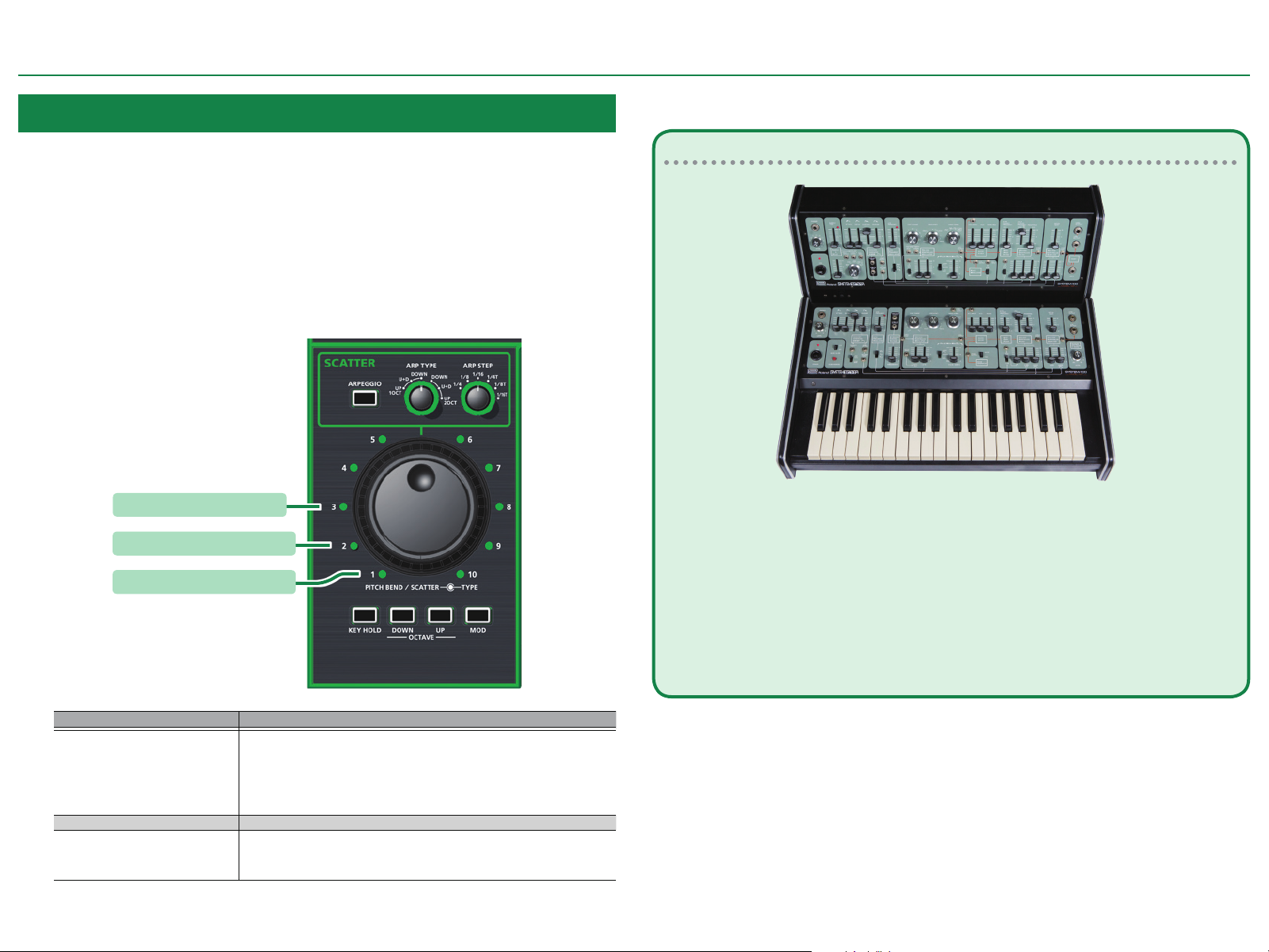
ARPEGGIO section
Here you can make arpeggio settings.
ARPEGGIO
ARP TYPE
ARP STEP
If this is lit, an arpeggio
plays.
Selects the arpeggio
variation.
Selects the speed of the
arpeggio.
SCATTER section
Here you can make settings for the
Scatter eect on arpeggio performance.
To use Scatter, make the [ARPEGGIO]
button light.
SCATTER
TYPE
SCATTER
DEPTH
KEY HOLD
OCTAVE
Selects a type of scatter.
Adjusts the amount of
scatter.
If this is lit, you can make
notes continue sounding
even after you take your
hand o the keyboard.
You can shift the
keyboard’s pitch range in
steps of one octave.
Page 4
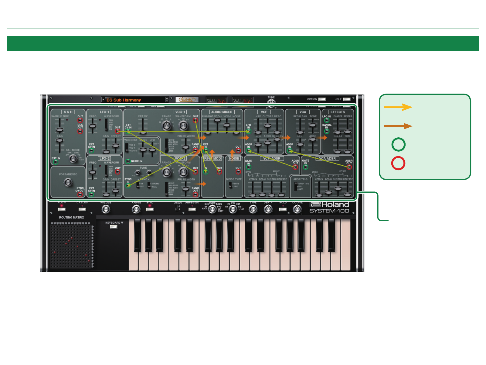
Modules and the Overlay Display
SYSTEM-100 has an overlay display function that lets you see how modules without cable connections are internally connected. The overlay display shows internal connections as yellow arrows.
To display the overlay, press the [SIGNAL FLOW] button.
Internal connection
Audio signal
Input jack
Output jack
Screen Structure
Overlay display
4
Page 5

SYSTEM-100 Input/Output Jacks and SYSTEM-1m Jack Area
SYSTEM-100 modules provide input/output jacks. You can create sounds by using these jacks to connect modules to each other.
Some of the input/output jacks are linked with the jack area of the SYSTEM-1m, allowing you to control SYSTEM-100 using CV/GATE input from an external device.
NOTE
If a patch cable is connected to an input jack of the SYSTEM-1m, the input signal to the SYSTEM-1m takes priority and the input signal to the corresponding SYSTEM-100 input jack is ignored.
SYSTEM-1m
Screen Structure
SYSTEM-100
5
Page 6

Making Connections and Editing Parameters
Be aware of the following points when connecting modules.
NOTE
5 Output jacks can be connected to input jacks. You cannot connect an input jack to another
input jack, nor an output jack to another output jack.
5 You can connect cables from one output jack to multiple dierent input jacks.
5 One cable can be connected to an input jack.
5 If a patch cable is connected to an input jack of the SYSTEM-1m, the input signal to
the SYSTEM-1m takes priority, and the input signal to the corresponding input jack of
SYSTEM-100 is ignored.
Input signal priority order
SYSTEM-1m input jack > SYSTEM-100 input jack > SYSTEM-100 internal connection
Connecting a Cable
1. Move the cursor to the input or output jack that
you want to connect, and drag.
2. Drop the end of the cable on the desired output or
input jack.
Drag
Disconnecting
1. Move the cursor to the input/output jack or to the middle of the cable that you
2. Drop the end of the cable where there is
want to disconnect, and drag.
The cable color changes to highlighted.
* If multiple cables are connected from an
output jack, you can click the jack to select a
dierent cable.
no jack.
The connection is broken and the cable
disappears.
* If the jack has an internal connection, it returns to the default state when you disconnect
the cable.
* In the
“ROUTING MATRIX” (p. 7), multiple connections can be disconnected or returned to
their default state by holding down the [Shift] key and dragging to enclose an area of the
red shorting pins.
Drag
Drop where
there is no jack
Changing a Connection
1. Move the cursor to the input/output jack or to
the middle of the cable whose connection you
want to change, and drag.
The cable color changes to highlighted.
* If multiple cables are connected from an output jack,
you can click the jack to select a dierent cable.
2. Drop the end of the cable on the desired output/
input jack.
Drag
6
Page 7
Making Connections and Editing Parameters
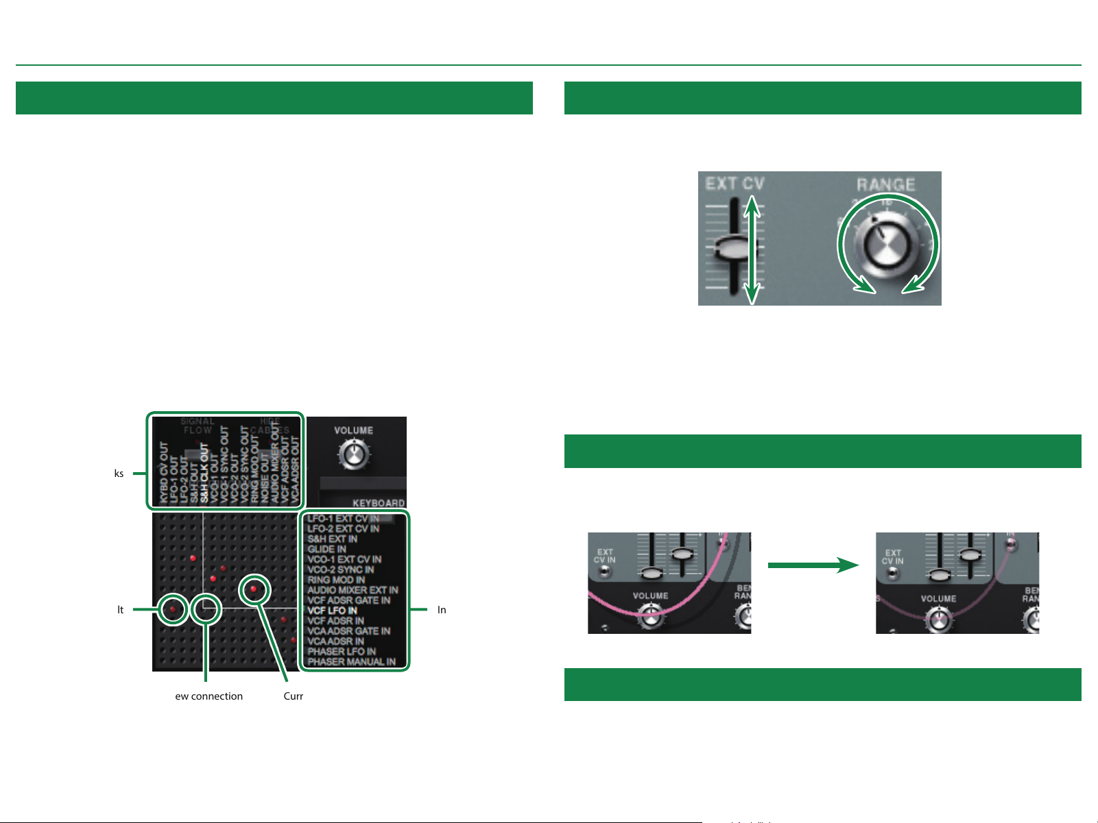
ROUTING MATRIX
SYSTEM-100 lets you make connections by using the ROUTING MATRIX, which works like a
routing switcher.
In the ROUTING MATRIX, the output jacks of the modules are assigned to the vertical columns,
and the input jacks are assigned to the horizontal rows. You can make a connection by clicking
an intersection. When a connection exists, a red shorting pin is shown.
If an input jack is already connected, and you click the intersection of that input jack with
a dierent output jack, the connection changes to the new connection (the last click takes
priority).
If you click a current connection (a red shorting pin), that connection is disconnected. This lets
you return the connection to its default state.
* If a jack has an internal connection, it returns to its default state (a dim red shorting pin)
when disconnected.
* By holding down the [Shift] key and dragging to enclose multiple shorting pins, you can
disconnect multiple connections or return them to their default state.
Output jacks
Operating Knobs or Sliders
To change the parameter value of a knob or slider, drag around the perimeter of the knob or
drag the slider up or down. When you drag, the value is shown below the knob or slider.
KnobSlider
* If you hold down the [SHIFT] key of your computer while you drag, or if you drag at a
distance from the controller, the value changes in smaller amounts, allowing you to make
ne adjustments.
* If you click the controller while holding down the [Command (CTRL)] key of your computer,
it returns to its default state.
Turning Cable Operation On/O
When you make a connection, the cable may overlap a knob or slider. If you want to operate
that knob or slider, turn o cable operation by making the [HIDE CABLES] button light. The
cable color turns semi-transparent.
Default
Input jacks
[HIDE CABLES] button On (lit)[HIDE CABLES] button O (unlit)
Current connectionNew connection
Changing the Cable Color
You can change the cable color to your taste. To change the cable color, double-click the
middle of a cable.
7
Page 8

Memory and Bank
1. Click the [PATCH] button.
The Patch Select window opens.
Bank
[NEW] button
Creates a new empty bank.
[LOAD] button
Imports a bank.
The selected memory
is shown in yellow.
[DELETE] button
Deletes the selected bank.
[SAVE] button
Exports a bank as a le.
A set of 64 memories is called a “bank.” By switching banks you can
access a large number of memories.
A bank of memories can be saved as a le.
Bank
Memory 01
Memory 02
Memory 03
Memory 64
Changing to Other Bank
1. Click the Bank eld.
The bank list window opens.
2. Click the bank that you want to recall.
By pressing the [=][?] buttons located at the right of the bank eld, you can switch to the
next or previous bank.
Exporting the Bank
Here’s how to export a bank as a le.
[SEND ALL] button
Sends all (64) memories in the
bank to the SYSTEM-1.
[WRITE] button
Saves an edited sound as a
memory in the bank.
[GET ALL] button
Receives all (64) memories
stored on the SYSTEM-1.
NOTE
All 64 memories are received into the currently selected bank,
overwriting the previous contents of that bank. If you want to
keep the state of the bank, create a new bank and receive the
memories into the newly created bank (p. 9).
[RENAME] button
Renames the selected
memory.
[READ] button
Loads a memory from a bank.
1. Click the [EXPORT] button.
The le name input window opens.
2. Enter a le name and save.
The le is written.
Importing a Bank
1. Click the [IMPORT] button.
The le selection window opens.
2. Select a le and load it.
The bank is loaded.
8
Page 9

Memory and Bank
Creating/Deleting a Bank
Creating a bank
Click the [NEW] button to create a new empty bank.
Deleting a bank
Here’s how to delete the selected bank.
1. Select a bank as described in”Changing to Other Bank” (p. 8).
2. Click the [DELETE] button.
A conrmation screen appears.
3. Click [OK] to delete the bank.
Renaming a Bank
1. Select a bank as described in “Changing to Other Bank” (p. 8).
2. At the left of the bank eld, click A.
Memory
The SYSTEM-100 manages 64 memories as one bank.
Loading a Memory
Here’s how to load a memory from a bank. When you load a memory, its settings appear in the
edit area and can be edited.
1. Click the number of the memory that you want to load.
2. Click the [LOAD] button. Or press the [Return (Enter)] key.
The memory is loaded.
* You can also load a memory by double-clicking a memory number.
Saving the Memory
Here’s how to save an edited sound as a memory in the bank.
1. Click the number of the memory in which you want to save the sound.
2. Click the [SAVE] button.
The memory is saved in the bank.
3. Edit the name and press the [Return (Enter)] key.
Renaming the Memory
1. Click the number of the memory that you want to rename.
2. Click the [RENAME] button.
3. Change the memory name. (Up to 16 letters)
Changing the Order of the Memories
Drag the memory number to change the order of memories.
9
Page 10

Keyboard shortcuts
Keyboard shortcuts for the Patch Select window.
Key Function
Command (Ctrl) + B Changes bank
Command (Ctrl) + I Imports bank
Command (Ctrl) + E Exports bank
Command (Ctrl) + N New memory
Command (Ctrl) + O Loads memory
Command (Ctrl) + S Saves memory
Up/Down/Left/Right Selects memory
Space Renames memory
Command (Ctrl) + C Copies memory
Command (Ctrl) + V Pastes memory
Delete *1
delete
fn + delete *2
Return (Enter) Loads memory
Command (Ctrl) + Z Undo
Command (Ctrl) + Shift + Z Redo
Command (Ctrl) + U Sends all memories to the SYSTEM-1
Esc Closes window
*1 Windows / *2 Mac
*2
Deletes memory
Memory and Bank
10
Page 11

Playing with the SYSTEM-1
By connecting the SYSTEM-1 to your computer (Mac/Windows), you can use the SYSTEM-100 in
conjunction with the SYSTEM-1.
Windows
The “SYSTEM-1 CTRL” shown as a MIDI port is the port used by the SYSTEM-100.
Do not use this port from your DAW.
Plug-Out
Send/Get Memories
1. Connect the SYSTEM-1 to your computer.
What is a “Plug-out”?
“Plug-out” is technology that allows a software synthesizer such
as SYSTEM-100 to be installed and used in the SYSTEM-1.
5 You can play the SYSTEM-100 on the SYSTEM-1 by itself,
without using a computer.
5 You can send the setting of selected bank to the SYSTEM-1.
5 You can use the knobs and sliders of the SYSTEM-1 to edit the
sound.
Plug-Out Procedure
1. Click the [PLUG-OUT] button.
A conrmation message appears.
2. Click the [OK] button.
A progress bar appears, and plug-out processing begins. This takes approximately one minute.
* If another software synthesizer is already plugged-out on the SYSTEM-1, a conrmation
message appears. Click the [OK] button to continue.
2. Turn on the MODEL [PLUG-OUT] button of the SYSTEM-1.
* In order to send or get a memory, you must rst plug-out (p. 11).
Sending the Memory
You can send the current SYSTEM-100 memory to the SYSTEM-1 and play it on the SYSTEM-1.
The sound is output from the SYSTEM-1’s OUTPUT jacks.
3. Click the [SEND] button of the SYSTEM-100.
The memory is transmitted.
Getting the Memory
If you’ve used the SYSTEM-1 to edit a memory of the plugged-out SYSTEM-100, here’s how to
load that memory into the SYSTEM-100.
3. Click the [GET] button of the SYSTEM-100.
The memory is loaded.
If an error message appears, check the following items.
5 Is the MIDI port specied correctly? (p. 12)
5 Is the SYSTEM-1 connected to your computer?
If an error message appears, check the following items.
5 Is the MIDI port specied correctly? (p. 12)
5 Is the SYSTEM-1 connected to your computer?
5 Is the SYSTEM-1’s MODEL [PLUG-OUT] button turned on?
5 Is the SYSTEM-100 plugged-out on the SYSTEM-1? (p. 11)
11
Page 12
Settings
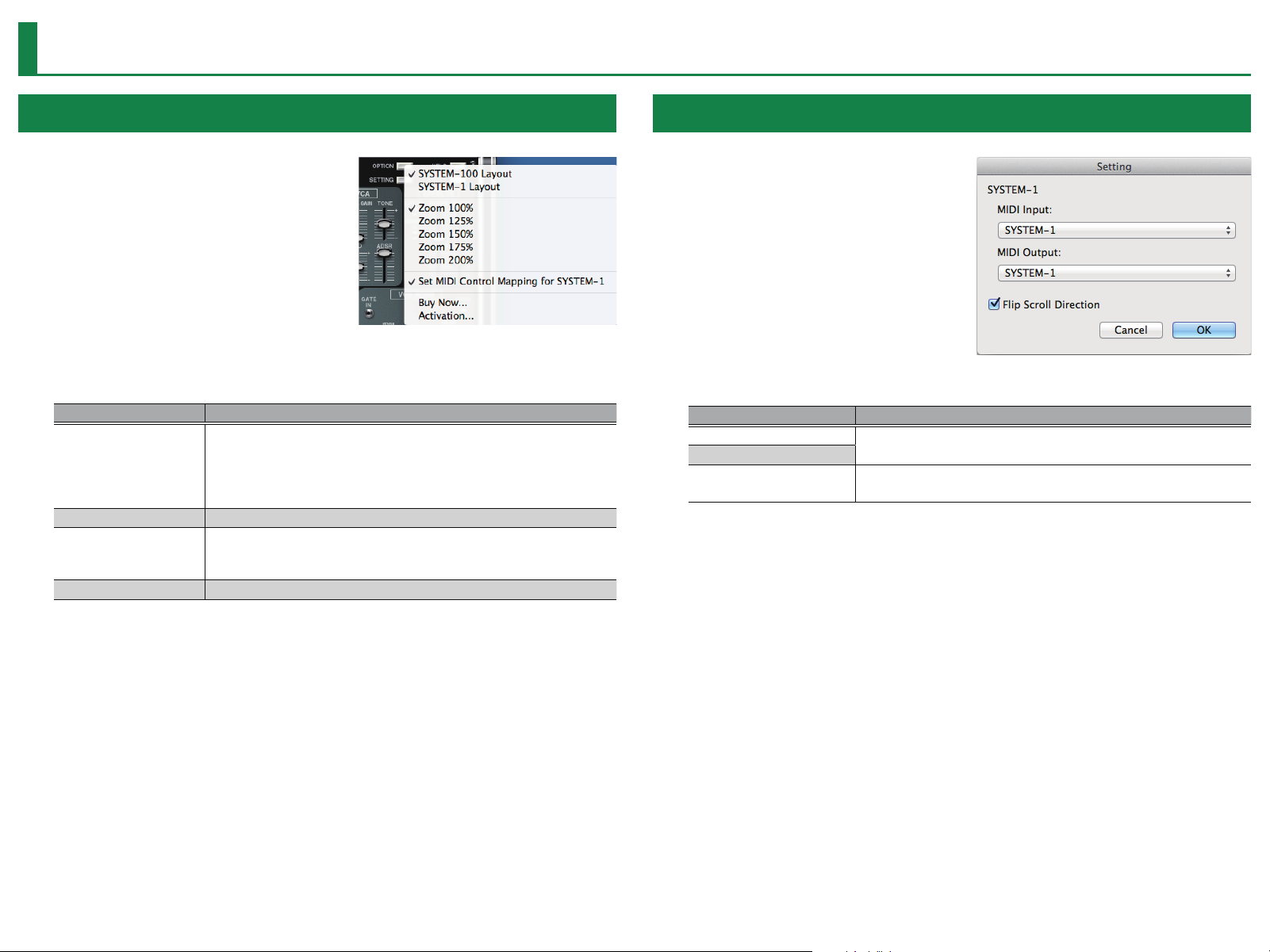
Option
1. Click the [OPTION] button.
2. Select items.
A ( is shown for the selected item.
Item Explanation
Changes the layout of the controllers in the main window.
SYSTEM-100 Layout
SYSTEM-1 Layout
Zoom Changes the size of the main window.
Set MIDI Control Mapping
for SYSTEM-1
Activation... Activates the SYSTEM-100.
SYSTEM-100 Layout: This layout is based on the 101 unit of the (original)
SYSTEM-100, with the 102 unit’s modules mixed in.
SYSTEM-1 Layout: The controllers are laid out as they are on the
SYSTEM-1.
Check this item if you want to use the SYSTEM-1 as a control surface for the
SYSTEM-100.
Here you can make MIDI mapping settings for the buttons and sliders.
Setting
1. Click the [SETTING] button.
The Setting window opens.
* Flip Scroll Direction is only on Mac.
2. Edit the parameters.
Parameter Explanation
MIDI Input
MIDI Output
Flip Scroll Direction
(Only on Mac)
3. Click the [OK] button.
* Your changes are remembered.
* If multiple instances of the SYSTEM-100 are running, these settings apply to all instances.
Choose “SYSTEM-1” (Mac OS) or “SYSTEM-1 CTRL” (Windows).
Inverts the direction of rotation when using the mouse wheel to edit a
value.
12
Page 13
Setting for the SYSTEM-1
Settings
When you want to play the SYSTEM-100’s sound (plug-in) with your SYSTEM-1, set the
SYSTEM-1 to the MIDI controller mode.
Once you set to MIDI controller mode, SYSTEM-1’s internal sound can not be played, and the
SYSTEM-1 can play the SYSTEM-100’s sound only.
* These settings are not available in SYSTEM-1m.
1. Turn the power on of the SYSTEM-1.
2. While holding down the MODEL [SYSTEM-1] and [PLUG-OUT] buttons, use the
SCATTER [TYPE] dial to set to MIDI controller mode.
MIDI controller mode
Local control ON
Local control OFF
About the SYSTEM-100
The SYSTEM-100 went on sale in 1975 as a “total system synthesizer” that allows you to
select and combine its constituent units.
A wide variety of sounds could be created by using patch cables to connect the modules
of the 101 basic unit and the 102 expander unit, and this unit played an important role as
an ideal synthesizer for studio recording.
Setting Explanation
Choose this if you’re using the SYSTEM-1 as a MIDI controller.
MIDI Controller Mode
Local Control ON Choose this when using the SYSTEM-1 on its own. (Default setting)
Local Control OFF
* Playing the keyboard will not produce the SYSTEM-1’s internal
sound.
* The SYSTEM-1’s internal sound is not produced even if the SYSTEM-1
receives MIDI.
Choose this when using the SYSTEM-1 in conjunction with your DAW.
* If the SYSTEM-1 is used by itself with this setting, playing the
keyboard will not produce sound.
Now, thanks to ACB technology, the 101 unit and 102 unit have been reborn as the
SYSTEM-100 Plug-Out Synthesizer.
13
Page 14

List of Modules
S&H (SAMPLE & HOLD)
Parameter Explanation
SAMPLE TIME Species the rate (clock) at which sample and hold occurs.
LAG Smooths the change in the signal.
EXT IN jack
S&H MODE
OUT jack Outputs the signal generated by S&H.
CLK OUT jack Outputs the rate (clock) signal specied by SAMPLE TIME.
* The S&H module has not the corresponding controller.
Inputs a signal to sample and hold.
* If you want to sample and hold the input signal from the EXT IN jack, set
S&H MODE to SIN (EXT).
• Selects the input signal to sample and hold.
• OFF: No input.
• SAW1: Sawtooth wave generated by LFO-1.
• SAW2: Inverse of the sawtooth wave generated by LFO-1.
• TRI: Triangle wave generated by LFO-1.
• SIN (EXT): Sine wave generated by LFO-1, or the signal input from the EXT
IN jack (if connected to EXT IN).
PORTAMENTO
Parameter Explanation
PORTAMENTO Adjusts the time over which the pitch change occurs.
KYBD CV OUT jack
Corresponding controllers
* Once you set to SYSTEM-1 Layout (p. 12) mode, the controllers are laid out as they are on
the SYSTEM-1.
* If you use the SYSTEM-1m, the corresponding controller (PORTAMENTO knob) is located in
PITCH section.
Outputs the pitch to be sounded.
The PORTAMENTO eect is added to this.
14
Page 15

LFO-1 / LFO-2 (LOW FREQUENCY OSCILLATOR)
Parameter Explanation
FREQ Species the speed of modulation.
EXT CV IN jack
WAVE FORM
GAIN Adjusts the gain of the signal that's input to the EXT CV IN jack.
OFFSET
OUT jack Output the signal generated by LFO-1 and LFO-2.
The signal that is input here applies change to the modulation of LFO-1 and
LFO-2.
Selects the signal generated by the LFO.
• SIN: A sine wave is generated.
• TRI: A triangle wave is generated.
• SAW: A sawtooth wave is generated.
• SQR: A square wave is generated.
• S&H: A signal generated by S&H (same as the S&H OUT jack) is output.
Osets the modulation speed.
If TEMPO SYNC is o, the speed is oset in 50-cent units. If it is on, the speed is
oset in units that synchronize with the tempo.
List of Modules
Corresponding controllers
* Once you set to SYSTEM-1 Layout (p. 12) mode, the controllers are laid out as they are on
the SYSTEM-1.
* The LFO-2 module has no corresponding controller.
15
Page 16

List of Modules
VCO-1 / VCO-2 (VOLTAGE CONTROLLED OSCILLATOR)
Parameter Explanation
EXT CV IN jack
EXT CV Adjusts the pitch modulation amount for VCO-1.
RANGE
WAVEFORM
PULSE WIDTH (Switch)
PULSE WIDTH (Slider)
OUT jack (VCO-1) Outputs the signal generated by VCO-1.
SYNC OUT jack (VCO-1) Outputs the sync signal generated by VCO-1.
DESTINATION
GLIDE Adjusts the pitch change at note-on.
Inputs the signal that modulate the pitch of VCO-1. If there is no input
(connection) to the EXT CV IN jack, the signal generated by VCO-2 is used to
modulate the pitch.
Species the octave.
* On the original SYSTEM-100 (MODEL-101/MODEL-102), there was a knob
named “FREQUENCY” that could adjust the frequency continuously (10
Hz–10 kHz). However on the SYSTEM-100 PLUG-OUT Software Synthesizer,
you can specify the frequency range (64, 32, 16, 8, 4, 2).
Selects the signal generated by the LFO.
• SAW: A sawtooth wave is generated.
• SQR: A square wave is generated.
• TRI: A triangle wave is generated.
When WAVEFORM is set to SQR (square wave), this switch selects the
waveform whose pulse width is varied. If you select MAN, only PULSE WITH
(slider) has an eect.
Adjusts the pulse width of the square wave when WAVEFORM is set to SQR
(square wave).
Selects the VCO that is aected by the GLIDE slider and LFO slider.
• VCO-1+VCO-2: The eect applies to both VCO-1 and VCO-2.
• LFO2: The eect applies to VCO-2.
• LFO1: The eect applies to VCO-1.
Parameter Explanation
The signal input here can be used to change the pitch.
GLIDE IN jack
VCO LFO Uses LFO-1 to change the pitch.
COARSE TUNE (Left side knob) Adjusts the VCO-2 pitch in semitone steps.
FINE TUNE (Right side knob) Makes ne adjustments to the VCO-2 pitch.
SYNC (Left side switch)
SYNC (Right side switch)
SYNC IN jack
OUT jack (VCO-2) Outputs the signal generated by VCO-2.
SYNC OUT jack (VCO-2) Outputs the sync signal generated by VCO-2.
If nothing is connected, an internal envelope built into GLIDE changes the
pitch.
If a signal is being input to the SYSTEM-1’s PITCH ENV jack, that signal takes
priority and the input signal to the GLIDE IN jack is ignored.
Switches whether the VCO-2 oscillation frequency is synchronized.
* If a signal is being input to the SYNC IN jack, the oscillation frequency
synchronizes to that input signal.
* If a signal is being input to the SYSTEM-1m’s OSC2 SYNC IN I jack, that
input signal takes priority, and the input signal to the SYNC IN jack is
ignored.
* Depending on the signal, synchronization might not occur in some cases.
Selects how VCO-2 will synchronize.
• STRONG: VCO-2 always synchronizes to the fall of the SYNC OUT signal or
the input signal (waveform) that is connected to the input jack. Choose
this if you want to synchronize at overtone intervals.
• WEAK: VCO-2 synchronizes to integer multiples (such as 2/3, 3/4, 4/3,
1/1, 3/2) of the VCO-1 SYNC OUT signal or the connected input signal
(waveform).
Inputs the signal that synchronizes VCO-2.
If there is no input to the SYNC IN jack, VCO-2 synchronizes to the SYNC OUT
signal of VCO-1.
Corresponding controllers
* Once you set to SYSTEM-1 Layout (p. 12) mode, the controllers are laid out as they are on
the SYSTEM-1.
16
Page 17
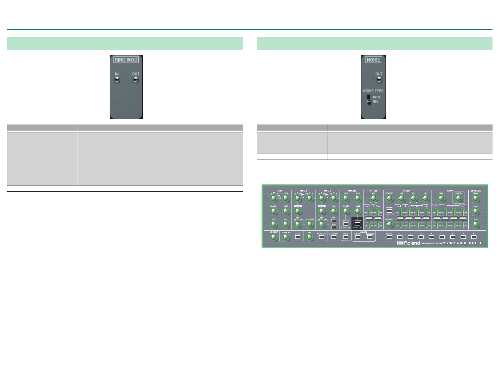
List of Modules
RING MOD
Parameter Explanation
The input signal is multiplied with the signal generated by VCO-2 to create a
complex waveform.
* If a signal is being input to the IN jack, the eect is applied to the input
IN jack
OUT jack Outputs the signal generated by the RING MODULATOR.
* The RING MOD module has no corresponding controller.
signal.
* If a signal is being input to the SYSTEM-1m’s RING IN I jack, that input
signal takes priority and the input signal to the IN jack is ignored.
* If there is no input to either the IN jack or the SYSTEM-1m’s RING IN I jack,
the eect is applied to the OUT signal of the VCO-1 module.
NOISE
Parameter Explanation
Generates noise.
NOISE TYPE
OUT jack Outputs the noise generated by the NOISE GENERATOR.
Corresponding controllers
• PINK: Pink noise is generated.
• WHITE: White noise is generated.
17
* Once you set to SYSTEM-1 Layout (p. 12) mode, the controllers are laid out as they are on
the SYSTEM-1.
Page 18

AUDIO MIXER
Parameter Explanation
Adjusts the volume. The signal that is adjusted depends on the state of
connections.
* If a signal is being input to the EXT IN jack, that signal is adjusted.
RING MOD / EXT IN
VCO-1 Adjusts the VCO-1 volume.
VCO-2 Adjusts the VCO-2 volume.
NOISE Adjusts the NOISE GENERATOR volume.
EXT IN jack Inputs the signal that is adjusted by the RING MOD/EXT IN slider.
OUT jack Outputs the signal mixed by the AUDIO MIXER.
* If a signal is being input to the SYSTEM-1m’s EXT IN I jack, that signal takes
priority and the input signal to the EXT IN jack is ignored.
* If there is no input to either the EXT IN jack or the SYSTEM-1m’s EXT IN I
jack, the RING MOD module’s OUT signal is adjusted.
List of Modules
Corresponding controllers
* Once you set to SYSTEM-1 Layout (p. 12) mode, the controllers are laid out as they are on
the SYSTEM-1.
18
Page 19

List of Modules
VCF (VOLTAGE CONTROLLED FILTER)
Parameter Explanation
HPF Species the cuto frequency of the high-pass lter.
CUTOFF Species the cuto frequency of the low-pass lter.
RESO
LFO
ADSR
KYBD CV
LFO IN jack Inputs the signal that is adjusted by the LFO slider.
ADSR IN jack Inputs the signal that is adjusted by the ADSR slider.
Boosts the region around the cuto frequency specied by CUTOFF (low-pass
lter). If this is set to the maximum, oscillation occurs at the cuto frequency.
Adjusts the amount by which the LFO modulates the cuto frequency
specied by CUTOFF (low-pass lter).
* If there is no input to either the LFO IN I jack or the SYSTEM-1m’s FILTER
LFO jack, this adjusts the amount of modulation produced by the signal of
the LFO-1 module’s OUT jack.
* If a signal is being input to the LFO IN jack, this adjusts the amount of
change produced by that signal.
* If a signal is being input to the SYSTEM-1m’s FILTER LFO I jack, that input
signal takes priority and the input signal to the EXT IN jack is ignored.
Adjusts the amount by which ADSR modulates the cuto frequency specied
by CUTOFF (low-pass lter).
* If there is no input to the SYSTEM-1m’s FILTER ENV I jack or the ADSR IN
jack, this adjusts the amount of change produced by the signal of the VCF
ADSR module’s ADSR OUT signal.
* If a signal is being input to the ADSR IN jack, this adjusts the amount of
change produced by that signal.
* If a signal is being input to the SYSTEM-1m’s FILTER ENV I jack, that input
signal takes priority and the input signal to the ADSR IN jack is ignored.
Causes the cuto frequency specied by CUTOFF (low-pass lter) to be
aected by the key that is played.
Positive (+) settings make the cuto frequency rise as you play higher notes,
and negative (-) settings make the cuto frequency fall as you play higher
notes.
Corresponding controllers
* Once you set to SYSTEM-1 Layout (p. 12) mode, the controllers are laid out as they are on
the SYSTEM-1.
19
Page 20

VCA (VOLTAGE CONTROLLED AMPLIFIER)
Parameter Explanation
INITIAL GAIN Adjusts the volume at which the input from the VCF is always output.
ADSR
LFO Allows the LFO to modulate the volume.
TONE Boosts the high or low-frequency range.
ADSR IN Inputs the signal that is adjusted by the ADSR slider.
Adjusts the output volume.
* If there is no input to either the ADSR IN jack or the SYSTEM-1m’s AMP ENV
I jack, this adjusts the amount of change at the VCA ADSR module’s ADSR
OUT signal.
* If a signal is being input to the ADSR IN jack, this adjusts the amount of
change at that signal.
* If a signal is being input to the SYSTEM-1m’s AMP ENV I jack, that signal
takes priority and the input signal to the ADSR IN jack is ignored.
List of Modules
Corresponding controllers
* Once you set to SYSTEM-1 Layout (p. 12) mode, the controllers are laid out as they are on
the SYSTEM-1.
20
Page 21

List of Modules
VCF ADSR / VCA ADSR (ENVELOPE GENERATOR)
Parameter Explanation
Generates an envelope from the selected gate signal.
• GATE: The envelope rises when a key is newly pressed.
ADSR TRIG
ATTACK / DECAY / SUSTAIN /
RELEASE
GATE IN jack (VCF ADSR) Inputs the signal that triggers the envelope generated by the VCF ADSR.
GATE IN jack (VCA ADSR) Inputs the signal that triggers the envelope generated by the VCA ADSR.
VCF ADSR OUT jack Outputs the signal generated by the VCF ADSR.
VCA ADSR OUT jack Outputs the signal generated by the VCA ADSR.
• LFO: When a key is held down, the envelope rises repeatedly at intervals
of the LFO-1 SQR (square wave).
• GATE+TRIG: The envelope rises each time a key is pressed.
Generate the envelope.
* If there is no input to either the GATE IN jack or the SYSTEM-1m’s ENV jack,
the envelope is generated according to the signal selected in the ADSR TRIG
section.
• ATTACK: Species the attack time of the signal.
• DECAY: Species the time following the attack during which the signal
falls to the level specied by SUSTAIN.
• SUSTAIN: Species the level.
• RELEASE: Species the time over which the signal decays.
* If a signal is being input to the GATE IN jack, the envelope is generated
according to that signal.
EFFECTS
Parameter Explanation
Adds a phaser eect to modify the character of the sound.
* If a signal is being input to the LFO IN jack, that signal modies the speed
of modulation; if no signal is connected to the jack, the internal LFO of the
PHASER
REVERB Adjusts the reverberation.
DELAY Adjusts the volume of the delay sound.
TIME Adjusts the delay time (the time by which the sound is delayed).
LFO IN jack Inputs the signal that adjusts the speed of PHASER modulation.
MANUAL IN jack Inputs the signal that adjusts the range of PHASER modulation.
Corresponding controllers
PHASER varies the speed of modulation.
• The internal LFO of the PHASER changes speed according to the position
of the PHASER slider.
* If a signal is being input to the MANUAL IN jack, that signal adjusts the
range of modulation.
Corresponding controllers
* Once you set to SYSTEM-1 Layout (p. 12) mode, the controllers are laid out as they are on
the SYSTEM-1.
* Once you set to SYSTEM-1 Layout (p. 12) mode, the controllers are laid out as they are on
the SYSTEM-1.
21
 Loading...