

Page 1
The Parameters of the 555
555
Copyright © 2018 ROLAND CORPORATION
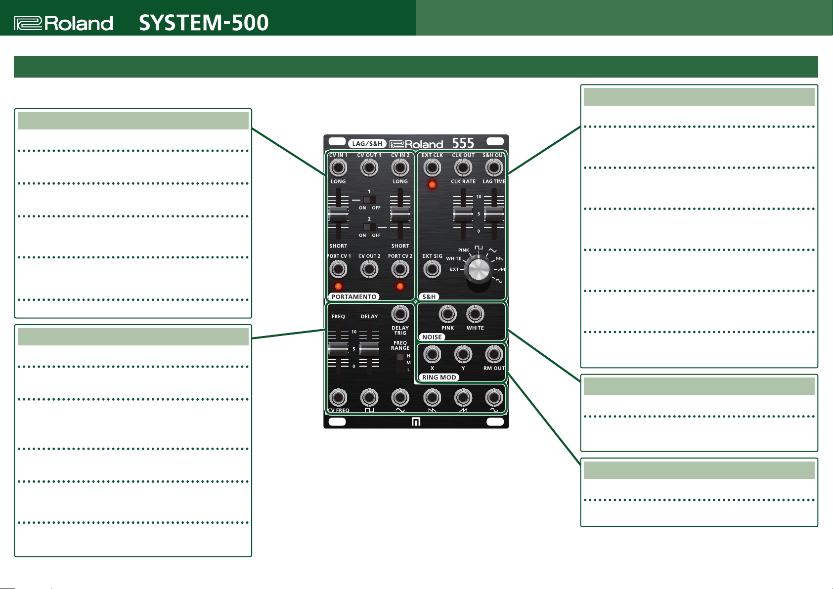
The 555 is a ve-in-one module with ve functions: PORTAMENTO, S&H, NOISE, RING MOD, and LFO.
PORTAMENTO
CV IN 1/2
These jacks input the signals to which you want to apply portamento.
CV OUT 1/2
These jacks output the waveform with portamento applied.
PORT CV 1/2
These jacks input a voltage used to control LONG/SHORT from an external
source.
LONG/SHORT
These sliders adjust the amount of portamento.
As the slider approaches SHORT, the signal approaches the original waveform.
ON/OFF 1/2 (Portamento)
These switches turn portamento on/o.
LFO (Low Frequency Osillator)
FREQ (LFO Frequency)
Species the frequency of the LFO.
DELAY/DELAY TRIG
When a signal is input to DELAY TRIG, the output amplitude from the LFO
temporarily becomes 0, and gradually returns to its original amplitude according
to the setting of the DELAY slider.
FREQ RANGE (LFO Frequency Range)
This switch species the LFO's frequency range.
CV FREQ
This jack inputs a voltage used to control the LFO's frequency from an external
source.
WAVE FORM
These jacks output a pulse wave, triangle wave, sawtooth wave, reverse
sawtooth wave, and sine wave.
About S&H
7
S&H is a function that remembers (samples) an input signal and maintains (holds) its level as specied
by a clock signal.
As the input signal, the S&H of the SYS-555 can use its own LFO output waveform, pink noise, white noise,
or the EXT SIG input signal. It holds this input signal as specied by the internal clock signal of the S&H or
an EXT CLK.
By combining various input signals and clock signals, you can create a CV that is unpredictable yet has
regularity.
By adjusting the LAG TIME you can smooth the changes in the CV that is output.
About LFO
7
The LFO of the 555 can output ve types of waveform, and also contains a delay function.
When a signal enters the DELAY TRIG jack, the output amplitude from the LFO temporarily becomes 0, and gradually returns to the original amplitude according to the setting of the DELAY
slider.
By using this in conjunction with the VCO, you can create delayed vibrato in which vibrato is applied a little while after the sound begins.
(Sample & Hold)
S&H (SAMPLE & HOLD)
EXT CLK
Input a clock signal to this jack if you want to use a clock from an external source
to hold the signal, instead of using the internal LFO.
CLK RATE
This slider species the frequency of the internal LFO that is used for HOLD. The
frequency is indicated by the blinking of the LED.
CLK OUT
The CLK OUT jack output the clock signal of the internal LFO. If EXT CLK is being
input, a clock signal is output at its frequency.
S&H OUT
This jack outputs a voltage that is held from the input signal. By adjusting the
LAG TIME you can smooth the changes in the CV waveform that is output.
LAG TIME
S&H contains an internal LPF. The output signal goes through the LPF before it is
output. This slider species the cuto frequency of the LPF.
SAMPLE SELECT/EXT SIG SW
This switch selects the input signal (SAMPLE). You can choose from internallygenerated pink noise, white noise, LFO output waveforms, or EXT SIG from an
external source.
NOISE
PINK/WHITE
The PINK jack outputs pink noise, and the WHITE jack outputs white noise.
RING MOD (Ring Modulator)
X/Y/RM OUT
The waveforms of X and Y are multiplied and output from the RM OUT jack.
01
Page 2
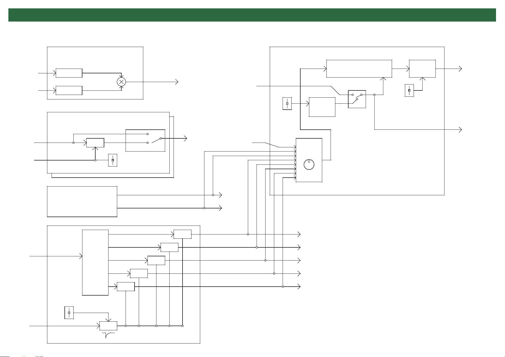
Block Diagram
X
Y
CV IN1
PORT CV1
RING MOD
DC CUT
DC CUT
PORTAMENT
VCF
LONG
NOISE
PinkNoise
WhiteNoise
OFF
ON
RM OUT
X2
CV OUT1
PINK
WHITE
EXT CLK
EXT SIG
S&H
CLK RATE
SELECT
SAMPLE and HOLD LPF
Jack SW
LFO
S&H OUT
LAG TIME
CLK OUT
CV IN
DELAY TRIG
LFO
DELAY
(Release Time)
Square
Triangle
Saw
Rev Saw
SIN
EG
Normaly High
VCA
VCA
VCA
VCA
VCA
Square
Triangle
Saw
Rev Saw
SIN
 Loading...