

Page 1
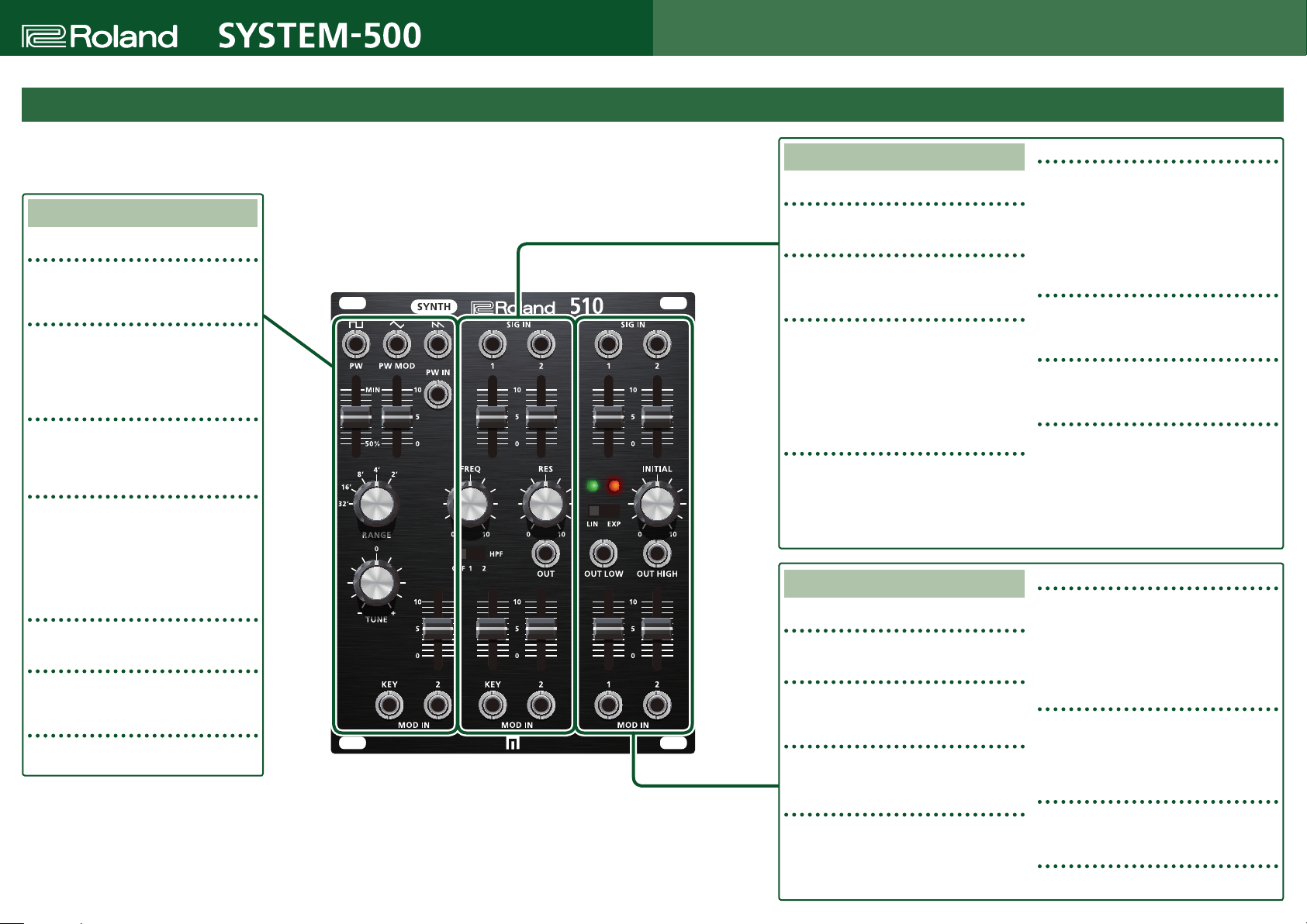
The Parameters of the 510
510
Copyright © 2018 ROLAND CORPORATION
The 510 is a three-in-one module with three functions: VCO, VCF, and VCA.
Several of the jacks are internally patched, allowing you to create sounds with minimal patching.
You can defeat the internal patching by inserting plugs into the jacks.
VCO
VCO OUT
These jacks output the signal from each VCO (pulse
wave, triangle wave, sawtooth wave).
PW (Pulse width control)
Specifies the pulse width (the ratio between the
upper and lower portions of the pulse wave).
For a symmetrical square wave, set the slider to
*
the "50%" position.
PW MOD (Pulse width modulation control)
Adjusts the depth of pulse width modulation
based on the voltage that is input from the PW IN
jack.
RANGE
Switches the pitch range of the VCO.
You can switch the range up or down in one-
octave steps in a ve-octave range from 32’ to 2’.
If you set this to the 8' position and apply a
*
voltage of 2V to MOD IN KEY, the middle C pitch
is produced.
TUNE
Makes ne adjustments to the VCO range.
Attenuator for CV input 2
Adjusts the level of the voltage that is input from
the MOD IN 2 jack.
MOD IN KEY/2
These jacks input voltages that control the VCO.
About pulse width
7
A pulse wave in which the upper and lower portions of the waveform have unequal width is called an asymmetrical pulse wave, and the numerical ratio of the upper
and lower widths (to be precise, the portion of one cycle occupied by the upper portion) is called the pulse width. The pulse width value signicantly changes the
overtone structure, modifying the tonal character of the sound.
If the pulse width is 1/n, the harmonics at multiples of ‘n’ are missing. For example, if the pulse width is 1/3 (33%), the 3rd, 6th, 9th, . . . harmonics are missing. The
*
technique of using a control voltage (such as LFO or ENV) to control the pulse width is called pulse width modulation (PWM).
VCF
SIG IN 1/2
These jacks input audio signals.
SIG IN level controls
These sliders adjust the level of the signals that are
input from the SIG IN jacks.
FREQ (Cuto frequency)
Adjusts the cutoff frequency of the filter (Low Pass
Filter).
Setting this to a low value lowers the cutoff
*
frequency, so that the high-frequency portion of
the signal does not pass through. Setting this to a
high value raises the cuto frequency, so that the
input signal is output without change.
RES (Resonance)
Boosts the frequency components in the region of
the cuto frequency.
By raising the resonance you can make the VCF
*
oscillate. You can use this as an audio source for
sound eects, or use KYBD CV to control the VCF
and play pitches from the keyboard.
VCA
SIG IN 1/2
These jacks input audio signals.
SIG IN level controls
These sliders adjust the level of the signals that are
input from the SIG IN jacks.
Indicators
These indicate the state of the output signal
(load: green, overload: red).
LIN/EXP control mode
Species whether the control voltage and setting of
the INITIAL knob aects the audio signal linearly or
exponentially.
HPF (High pass lter)
Adjusts the cutoff frequency of the HPF (High Pass
Filter).
At the OFF setting, the original waveform passes
*
through without change. As you raise the setting
to 1 or 2, the cuto frequency rises, allowing only
the high-frequency portion of the signal to pass
through.
OUT
These are output jacks. These jacks output the signal
from the VCF.
Attenuator for CV input
This slider adjusts the gain of the voltage that is input
from the MOD IN KEY/2 jacks.
MOD IN KEY/2
These jacks input a voltage that controls the VCF
color.
INITIAL (Initial gain)
Adjusts the VCA’s initial gain (the gain when there is
no control voltage at all).
If you are using only a control voltage to control
*
the VCA, use this knob to specify the initial gain
appropriately for the LIN/EXP control mode
setting: 0 (for LIN) or in the region of 1 (for EXP).
OUT LOW/HIGH
These are output jacks. These jacks output the signal
from each VCA.
The OUT LOW jack outputs a lower-level signal than
the OUT HIGH jack.
Attenuator for CV input
These sliders adjust the gain of the voltages that are
input from the MOD IN 1/2 jacks.
MOD IN 1/2
These jacks input voltages that control the VCA.
01
Page 2
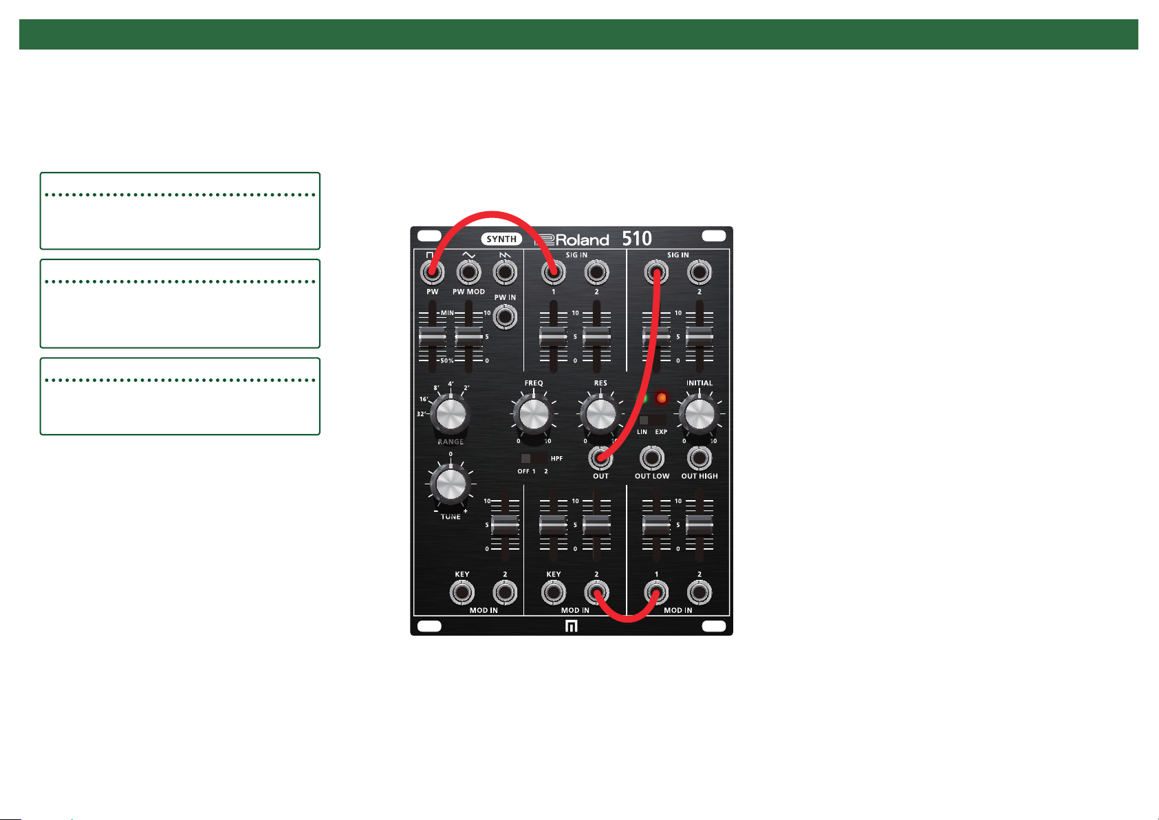
Internal Patching
Square wave & VCF SIG IN 1
If no plug is inserted in VCF SIG IN 1, it is patched to a square wave.
VCF OUT & VCA SIG IN 1
If no plug is inserted in VCA SIG IN 1, it is patched to VCF OUT.
If a plug is inserted in VCF OUT, it is not patched to VCA SIG IN 1.
*
VCF MOD IN 2 & VCA MOD IN 1
If no plug is inserted in VCA MOD IN 1, it is patched to VCF MOD IN 2.
Page 3

Block Diagram
Slider
PW IN
PW
Square
Square OUT
SIG IN 1
SIG IN 2
Jack SW
Slider
SW
OFF
HPF1
HPF2
HPF1
HPF2
MOD IN 2
MOD IN KEY
VCO
Slider
Triangle
Saw
TUNE OCT
MOD IN KEY
Triangle OUT
Saw OUT
Slider
FREQ
Slider
VCF
LPF -24db
MOD IN 2
RES
Slider
Jack
SIG IN 1
OUT
Jack
SIG IN 2
MOD IN 1
Slider
Slider
Jack SW
MOD IN 2
Slider
INITIAL
Slider
SW
EXP
OUT HIGH
VCA 1
OUT LOW
ULOG
LIN
 Loading...