

Page 1
Before using this unit, carefully read leaet “USING THE UNIT SAFELY.”
* 5 1 0 0 0 4 9 0 7 3 - 0 2 *
About the Manuals
Owner’s manual English Copyright © 2015 ROLAND CORPORATION
The documentation for this unit consists of the following materials.
5USING THE UNIT SAFELY (separate leaet)
Read this rst. It contains notes that you must observe in order to use the unit correctly.
Part Names and Descriptions
Front side
21
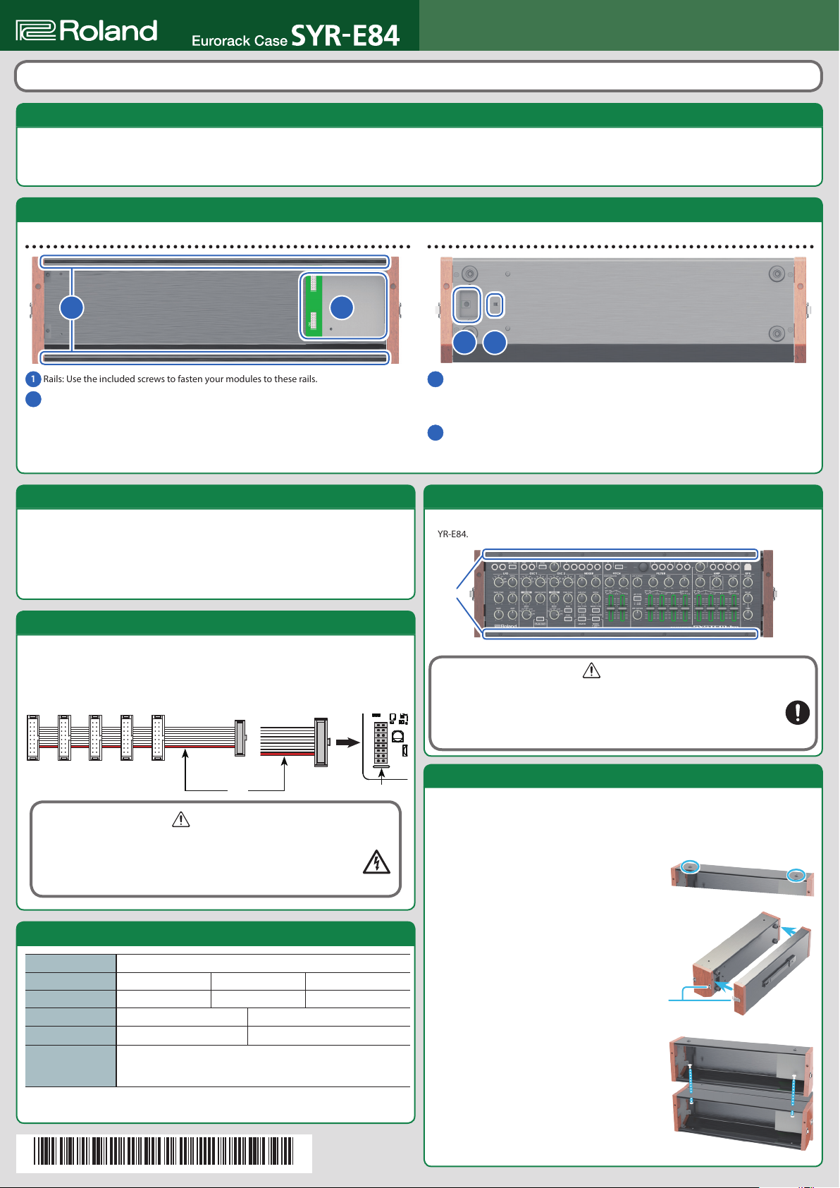
Rails: Use the included screws to fasten your modules to these rails.
1
Bus board area: This is the power supply unit. It provides 12 V, 5 V, and -12 V voltages.
2
* Do not touch any of the printed circuit pathways or connection terminals.
About the Current Capacity
The bus board of the SYR-E84 provides the following current capacities: +12 V is 2000 mA,
-12 V is 500 mA, and 5 V is 300 mA. When assembling your modules, check the current
consumption of each module and take care not to exceed the allowable capacity for each
voltage.
* If the allowable capacity is exceeded, a safety feature of the bus board will operate, and
power will no longer be supplied.
5Owner’s Manual (this document)
This explains how to make connections, and describes the specications of the unit.
Rear side
3 4
AC adaptor connection port: Connect the included AC adaptor here.
3
* Place the AC adaptor so the side with the indicator faces upwards and the side with
textual information faces downwards. The indicator will light when you plug the AC
adaptor into an AC outlet.
Power switch: Turns the power of the bus board on/o.
4
* This unit is equipped with a protection circuit. A brief interval (a few seconds) after
turning the unit on is required before it will operate normally.
Installing Modules
Use the included Eurorack installation screws to fasten your modules to the rails of the
SYR-E84.
Rails
Connecting the Power Supply Cable
When connected to the bus board, the power supply cable can supply power to up to ten
modules. To connect the power supply cable, grasp the black connector and insert it, making
sure that the wire marked in red is aligned with the white line of the bus board connector.
* When circuit board installation is complete, double-check your work.
Red
WARNING
7Electrocution hazard
* Before you attach the power supply cable, turn o the power of the
SYR-E84 and disconnect the power plug from the AC outlet.
* Do not touch the electrical terminals when attaching the power supply cable.
Main Specications
Power Supply AC adaptor (DC 12 V)
Current Capacity 2000 mA: +12 V 500 mA: -12 V 300 mA: +5 V
Power Consumption 30 W: +12 V 10 W: -12 V 3 W: +5 V
Dimensions 481 (W) x 135 (D) x 157 (H) mm 18-15/16 (W ) x 5-3/8 (D) x 6-3/16 (H) inches
Weight 2.4 kg 5 lbs 5 oz
Accessories
* In the interest of product improvement, the specications and/or appearance of this unit
are subject to change without prior notice.
Owner’s manual, Leaet “USING THE UNIT SAFELY,” Eurorack Installation
screw (40 pcs.), 16-pin Eurorack power supply cable (2 pcs.), AC adaptor,
Power cord
Roland SYR-E84: Eurorack Case
White
CAUTION
7Keep small items out of the reach of children
To prevent accidental ingestion of the parts listed below, always keep them out of
the reach of small children.
5Included Parts: Eurorack installation screws
5Removable Parts: Stacking screws
Stacking SYR-E84 Units
SYR-E84 units can be stacked.
* In order to stack units, you’ll rst need to remove the modules (including the Eurorack
power supply cables).
* When stacking units, you must attach the covers to prevent the units from overturning.
Remove the two stacking screws from the top
1.
surface of the SYR-E84 that will be on the bottom.
Align the pins of the cover with the holes on the back
2.
panel of the SYR-E84, and use the left and right latches
to secure it.
In the same way, attach the cover to the SYR-E84 that is
to be stacked.
Secure with latches
Using the stacking screws that you removed in
3.
step 1, fasten the two SYR-E84 units together.
 Loading...