

Page 1
[eRofand
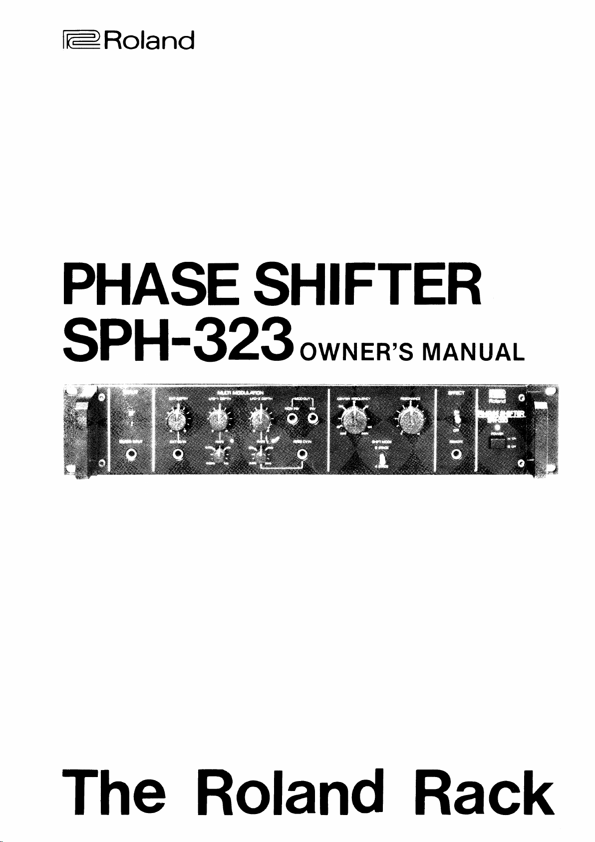
PHASE
SPH-323owNER's
SHIFTER
MANUAL
The Roland Rack
Page 2
PHnsE
The
SPH
phase
type
multiple
duce
means
by
quency
wrth
an optronal
voltage
sHtrrgnl
rs
323
shifter
phase
of
dual rnternal
oscrllators
source. lt is a hrgh
unit desrgned for
rncludes
and
both
balanced inputs
well
as a special
and output.
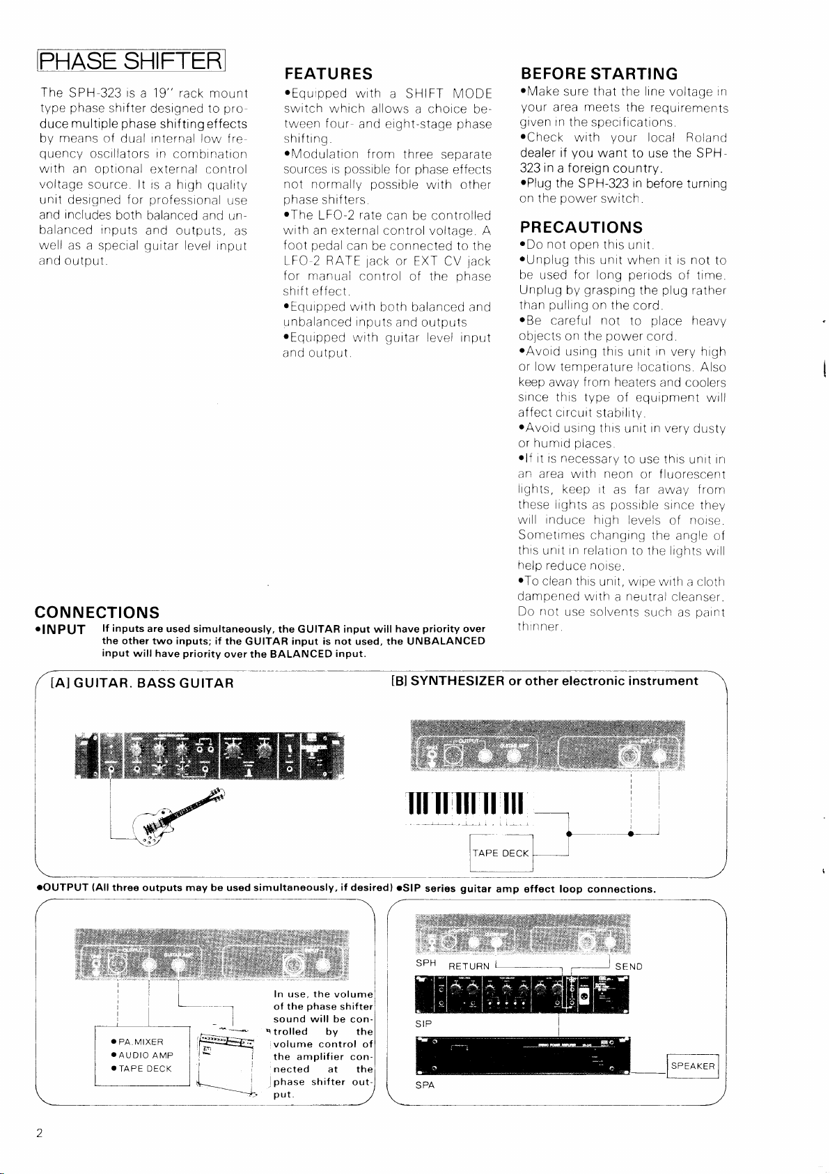
CON
N ECTIONS
oINPUT
lf inputs
the
other two inputs;
input
will
rack
a 19"
designed
shif
ting
mount
prct
to
effects
low f re
in
combinatron
external
control
qualit,
professional
balanced
and outputs,
guitar
level input
are used simultaneously,
priority
have
use
and urr-
as
if the
GUITAR input is
over the BALANCED
FEATU
oEquipped
swrtch
tween
R
ES
with
a SHIFT MODE
which
f our
allows a choice
and eight-stage
shif trng.
oModulation
sources rs
not normally
phase
shifters
oThe
LFO-2
wrth
an external control voltage.
pedal
f
oot
LFO 2 RATE
for manual
from
three
possible
for
possible
rate
can
be controlled
can
be connected to the
or EXT
lack
control
of the
shift effect
oEquipped
unbalanced inputs
.Equipped
with
both balanced and
and outputs
guitar
with
and output
the
GUITAR
input will have
not
used, the UNBALANCED
input.
separate
phase
with
CV
level
priority
be-
phase
effects
other
A
jack
phase
input
over
BEFORE
rMake
your
given
oCheck
dealer
in
323
oPlug
on the
STARTING
sure that the lrne voltage
meets
area
in
the specif ications.
with
you
if
foreign
a
the
SPH-323
power
the requtrements
your
local Roland
want
to use the SPH
country.
in
before
switch.
PRECAUTIONS
oDo
not
.Unplug
be
Unplug
than
oBe
oblects
oAvord
or low
keep
thrs unit
for
used
grasping
by
pullrng
careful not
on the
using this
temperature
from heaters
away
srnce thrs type
opcn this
affect
crrcuit
oAvord
or
.lf
an
Irghts,
these
usrng this
places
hun-rrd
rt rs necessary
area wrth
keep rt
lights
will induce
Sometimes
thrs
help
oTo
dampened
Do
rn relatron
unit
reduce noise.
clean thrs
wrth
not
use solvents
thrnner.
unit.
when
perrods
long
the
on the
cord.
to
power
cord.
untt
locations.
of equipnrent
stabilrty.
unit
10 use this
neon
or fluorescent
Iar
as
as
fiossrble
high
leveis
changing
to the lights
unit, wtpe wrth
neutral
a
such
turning
it is not
of
time.
plug
rather
place
heavy
rn
very high
Also
and coolers
wrll
rn
very
dust,
unrt
away frorn
since they
nolse.
of
the
angle of
wr
cloth
a
cleanser.
patnt
as
rn
to
tn
ITAR.
G U
ffiffi
oOUTPUT
(Allthree
O
PA, MIXER
.
AUDIO
.TAPE
outputs
AMP
DECK
G U ITAR
may be
used simultaneously,
In use, the
phase
the
of
will be
sound
r
trolled by the
volume control of
the amplifier connected
phase
.l
put
at the
shifter
if
desiredl
-)(
H",
i$ ll
volume
shifter
con-
out-
SYNTHESIZER or other electronic instrument
tBl
oSlP
series
guitar
amp effect loop connections.
ll
RET URN
l
Page 3
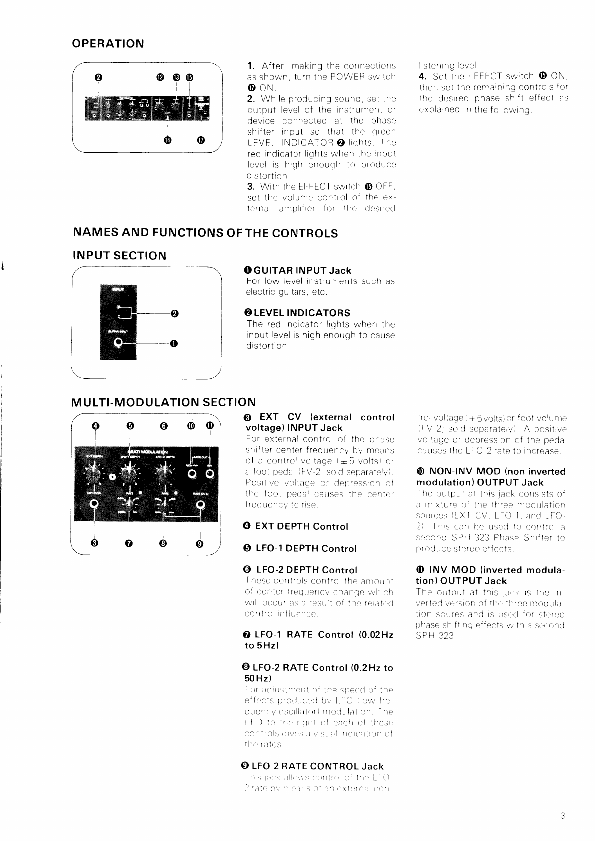
OPERATION
NAMES
INPUT
SECTION
AND
FUNCTIONS
OF THE
--)
i
I
I
1.
After
as shown,
making the
turn the POWER switch
connecttons
(DoN
2. Whrle
output
devrce con
shrfter
LEVEL
red
level is hrgh
drstortron.
3. With
set
ternal
producrnq
level of the
nected
rnput so that
INDICATOR
indicator
the volume control
lights
the EFFECT switch
amplrf
soLrnd,
at
when
enough
ier
f
or
instrument or
liqhts
€)
to
the desri-ed
the
the
the
prodLrce
of
CONTROLS
OGUITAR
For low level instruments
electric
O LEVEL
The red
input level
distortion.
INPUT
guitars,
Jack
etc.
INDICATORS
indicator
is
high
lights
enough
such as
when the
to
the
set
phase
green
rhe
rnput
OFF,
O
the
ex
cause
listenrng
4.
then
the
explarned
ievel.
the
Set
the
set
desrred
rn
FFFECT switch
remainrng controls
phase
the
shift
followrng
(D
effect
ON,
for
as
LTI-MO D U LATION
M U
i,tj
\oooo
SECTION
O
voltage)
For
shif ter
of
a control voltage
foot
a
Postttve
the foot
freqrrencv
O EXT
LFO-1
O
LFO-2
O
These
r:enter f reqirencV
of
wtll
ccntrol
LFO-1
O
to 5 Hz)
o
LFO-2
50 Hz)
Fctr
effr:cts
tlLrenc\/ oscillator)
LFD 1(.r
(-on1roIS
he
t
EXT
CV
INPUT
external
pedal
occlr
adllrstnr*
ra
tr:s
control of
center f
\FV
voltaqe
pedal
rrsL.
to
DEPTH
DEPTH
DEPTH
controls
;t
as
inflrrerce:
RATE
RATE
rr
irroilLrr.i:cj
rrqhl
ti-rrl
!li\rls
(external
Jack
the
reouencv
(+
5
2;
sold
separatelv)
or
deftressron of
causes the
Control
Control
Control
ccintrol the.
cha;r1c w,bre
resLilt
of tltr:
Control
Control
t of the
bv
p1
:l
visl.tatI
(0.2H2
slter,rl
LFO
nrodulatron
erach
inclrc--;ttron
control
ohase
means
bv
volts)
centcr-
;ntotinl
rr-.iettr-.(i
(0.02H2
to
of
thr:
(lovv
frr:
ire
T
of theset
tt1
lrol
(=V
voltage
causes
or
(E
modulation
The
a
soLrrces
2l
sccond
prroducc
(I)
tion)OUTPUT
The
h
vertecJ
tion
lrhase
SPH
voltage
NON-INV
nrxture of
Thrs
INV
(
+
2;
oLrtpLtt
outpLrl
versron
sortres and
shrf trnc-1 ef
323
5
sold separatelv)
or depressron
the
LFO 2 rate
MOD
OUTPUT Jack
)
at thrs
the
{EXT
CV, tFC
catr
br:
SPH 323 Phlrsp
stcreo ef
MOD
at thrs
or f oot volunre
volts)
of
to
(non-inverted
consrsts
lack
rrodulation
three
1,
[tSccj to
fects
(inverted
Jack
lack
of the
thrr:e
rs
Lrsed f or
fects
wrth
posrtrve
A
pedal
the
increase
of
and I fO
r:orrtrol
Shrfter to
modula-
rs the
r.rodula
a se-'cond
,t
in
stereo
O
LFO-2 RATE
li,s
;tr'[. lllqrr,15r i'irlllrt
r,l1rl
l)i,'",,''-,ttS
.l
CONTROL
of
(rf
ari
titr: i !()
(:t\terrlal
Jack
rlOtt
Page 4

PHASE
SHIFT SECTION
CENTER
@
trol
Thrs control
requency
f
(D
RESONANCE
means
By
can be
cent
of the
of this
induced
phase
the
FREOUENCY
initial
the
sets
phase
shift effect.
Control
control,
in
the
shift effect.
feedback
circutt
Con-
cenler
to ac-
SHIFT
@
The B-STAGE
the
while
duces
MODE Switch
strongest
the 4
STAGE
phase
soft
position
phase
position
shift
shrft
effects.
produces
effect
pro'
EFFECT
REAR
SECTION/POWER
PANEL
(D
EFFECT
Controls
the
effect.
(D
REMOTE
A foot
can
be connected here for remote
control
functron
swrtch
POWER
O
Lamp
Switch
the
swrtch
the
of
For
(D
must
Switch
ON/OFF f unction of
Jack
(FS-i;
sold separately)
EFFFCT
thrs, the
ieft
be
at ON.
and Pilot
ON/OFF
EFFECT
UNBALANCED INPUT
A.
ard 1 /4"
B
BALANCED
nector)
lf
both
UNBALANCED
prrorrty.
c.'GUITAR
r.9
UNBALANCED
(Standard
€
nector
AII
sirn
J-,IGROUND
For making
nections with
phone
are used
BALANCED
(XLR
three
lta neously.
u
jack)
INPUT
simultaneously,
INPUT
AMP
OUTPUT
OUTPUT
phone
114"
OUTPUT Con-
connector)
outputs
Terminal
common
may
other eouioment
I
I
(XLR
jack)
be
ground
(Stand.
con-
the
A has
Jack
Jack
used
con-
I
I
I
c
I
,6\
I
I
@
Page 5

PHASE
ABOUT
When a
an
work
orrginal
result
verv
The
drrectlv
stages
Wrth erqht
USING
The
the
phasc
d'ced
s6f
6
shLf
,r-,
@
i u^,,f
,-t.,
frerlirel,'',
effect
The
shrft
CENTFR
ihr:
the SHIFT
controls
TION
hOVr"'
THE
passed
sound
electronic
then
,
souncl
is
a
narrow
nunrDet o1 rtant.cllattotrs
related'to
rn
H IFT
S
a.:r frrrtr,\,een trn"o
cho
,qf-
Ir,
r.1iic11
t
Iirr
trr.,t
jr.{ts
tr(_r{,it
trr-f-,
rn tta
netvrork;lre
B ESON
rn
sectro.r
lilt,t
is
phase
combrned wrth
canceilation
b,:nds
prhase
the
staoes,
THE
r',1C
f1
l-.1
sli]rle
s
:
rrrod.tr:ecl bv 4 staqe
RESO\A\]CE
1t:rtdbllr.k
ll C;rtij€-.rrs
lr;lr'(is
r:;rrantc-'ters
FRFCUENCY
ANCF
i\1ODE
thc
i'f
r-c,r'!r'r irr,lilllfle\'
shrftrnq
ustncl
a
of
f recllencres
of
the
sh
foLrr
PHASE SHIFTER
D E srry
tch
hard effect
a
Dhase
tf'te CanCele;d
IntenSlfV
to
of
detternttned
control
svrrtch
ll'lilil VIODULA
thc
1rarc1
SHIFTER
throuqh
net
the
n'lxer,
one
nlnrDer ct
f
t
shtftrnq and
ntc-, the c
controi
the:
more
or
network
bancls arer
(D
grves
ot
types
trlro
control
the
the
1)hilsl
t[t.;
bv
(9
(8,
ancl
(D
Tl-re
l^t'tli
trt'r
tlr-
detern,
rs
t
with f
canceled and
canceled
are
bands
bands are
trom
pitch
called
CENTER
the f
on
rnrtral
celed bands,
swept.
Standard
can
DEPTH
FC
L
DEPTH
2
rr,rnriilnrncl
wril
the
tf're cerrter
,rrd
O) wrll cletermrne the
,s\\,cclf)Inil
-[f.e
L;c'niltlex
the threc
c.,f
S'v^i,(-rC[,]tltl
r)riF
relattvely
pornt
the
and
are
Ilte
c:enter
FREOUENCY control
ront
center
phase
prodLtced
be
control
1
DFPTH
r
DEPI
determrne
.ienter freqIrenc',,
rnitral
frequenc',,
rclate-'ci
the
SPH 323
sw.rep
VVfCft
SOlrCf:,,
oLrr
even
of vrerl",
centererJ
fregLtencv.
panel
rs
frequency
which a control
after
t
shrf
leavrnq thr: EXT
by
and
O
controlOor
ontrol
@
r.irrliio
Fl
bow fai'
RATF
.an
pa1'ler
sourccs
[].it-rt
r,f
Iitrlk
stages,
The
canceled
rn
spactnq
mustcal
of
on what
to
used
ef
[)ro(1ri.f-
set
of the
fe<rt
Datter
the r the
e
ihe
'
;tt
O"
iOorOl
i-rw,atv
sctillq
will swer:1;,
c,onlrol {Orrr
spreecl
of
rts
belr--altse
rvallable
(rra.
ir
iitt:
DEP
two
ts
The
(D
the
can
trs
FC
L
ii'r,
f
ronr
tirt:
vr)i\,,
for
tn.lil
f
n
input rs
frequency
rnrtral
center
uses a
323
Internal
to
used
sweep
above
and
f requency The S PH
combinatron of
sources
(LFO
2t and one externai
to
CV)
control
sweeptnq of
produces
rrq
the
effect
controls(O,
controls
anlount
be
rcq
f
EXAM
f a hrr;h
whrch
of each control
for sweeptnQ
used
uenc1,
PLE:
evel
DEPTHO)
level
of fast
the result
O),
tbe sweep The
the
center
famrlrar
O,andG))
cletei'mlne
of slc-.w
is
cornbrned
(LFO-2
LFO
will
be
rnodulatinq wave like
below:
the
center
beiow
l
and tFO
source
f reqLlency
phase
mrxer
as
sol;rcc
the
center
ttFO
I FO
with
DEpTn
a
compound
that
shown
the
two
(EXT
shrft
level
thrl
low
a
to
1
REMOTE
EXT
1.
CONTROL
CV
2. RATE CV
3. EFFECT
ON/OFF
f
a f oot
(:t(l:)l
to
-pf
foot
.r
rarse
set
As
v'olLrrlc
tl
r'11:,
:i-il(llj(-':a',,
sct flv
sFrt
irsinq 1i-e
11.-
volunre
ro rhe
LackO,
the
bv
abovr:,
rer-teCJ
t.
i'fr.)lF.r
value
CUENCY
FBECUENC\
usi:cJ
vt'ben
LXT DEPTH control
Ir
if
necred
TROL
to
rate
@
rtontrolO
ltnril
of ths
conncclrno a toot
Bv
the
to
thet
on and
EFFECf
pi'rase
off
When using
EFFECT
the
1tr:rliri
p
lf
i:XT
;r,.
l.rr,tj
.lit1
thc
CtNTFfl
celtroi
,l.l'+r
(D
i-i-rnirol
lower
ihc
toot
I't'
,l
pecial
LFo
peclal
tire
rate
L=C 2
the
IFO 2 RATE
the
wrll rieternrrne
rale
1FC 2
CN'CFF
sirf t
effec--t
f rom a remote
function,
this
ONi
OFF
oN.
,i
i'
zl,,
s itlrr
C\",'
ri:r;k@
':tl\a
r
i
tl.lrt
i
CE\-t
(D.arr
rJr:srra:ci
itncl
Dr;
20) s con
r:an
hp
'r
n
ts(,o
CCN
Lrspd
t,r
ihe
lrlrit
Dedal
Ocar
(FV
RATF
2
aitovc ihe
control
LFO 2 RATE
lov",r:r
the
swrtcfr
lFS
lack
a;rlr be-,
tltrnccl
posrtton.
leave
switch
ti,r,
'f-r,
'i
.ri
F
R
i;i,
'll-e
I
@
(D
t
,
Page 6

BLOCK
UNBAL
L
DIAG
INPUTUNTBAL tNPUr
'1,
BAL INPUT N i
INPUT
GUITAR
FATECV'[T
n\r--
ui
I l--:
\-/
T'I
U
I
RAM
i
r--
l.ll
"tto,lANCE
u-
PHASE
CIRCUIT
F]IFT
S
|
|
\LXvL'rv
CIRCIJIT
4
SHIFT
8
v
oi-,E
,v
D
,1
---Yfl
LlNOr,t
UNBAL
voo
cur
tNV
OUTPUT
nT,
o
Rack M ou nting
sPH-323
:,,,.
.i'-t
I
.,.
1'
'
.t
:
:r,t
the
,i,,.)
'
;,'
H@
!FO_2
:f
,,
t,
r.l
r'
.i
/'rr a
t illllllft
'\'*
al* r'
l_plllf
"
''-r
T'I
i-,
I
1+
!.r
ii
5mm
It->-
--1""5--
l,-
---yn
H
MoD
tNV
our
)
Page 7

SPECIFICATIONS
r
PHASE
Maximum
SHIFTER
Input
Balanced:
Unbaianced:
Guitar.
Maximum
Output
Balanced:
Unbalanced:
Amp
Guitar
Phase
Shift
4-stage
.
B-stage
Center Frequency
Frequency
Response,
20Hz-30kHz;
Harmonic
Effect O
Distortion
FF
4-stage:
B-stage:
Residual
Balanced
Balanced
Guitar
Output,
Low
Frequency
LFO-1
:
Noise
Output,
output,
0
02Hz to
(JlS
ef
Oscillators
triangle
LFO-2
.
0
to
2tz
triangle
Power
Consumption:
Dimensions:
482(y/)
x
92(H)
19"(ElA-2U)rack
Weight:
Specifications
without
subject
notice.
r
SPH-323
Level/
+
+
lmpedance
20dBm/15kO
20dBm/15kO
-ZjdBml1MO
Levef / lmpedance
+
20dBm
+
20dBmi
r
1200A
6000
20dBm/3kO
approx 7O0o
approx
Sweep
1400o
Range:
50Hz-15kHz
effect
+
OFF:
1dB
0.004o/o
0
015%
0.02o/o
"A"Weighting)
fect
ef
effect
fect
5112,
wave
50
Hz;
wave
FF:
O
-
100dBm
ON:
-
BOd Bm
OFF:
-
100dBm
A10Vp-p
a
10Vp_p
7
W
x240(D)mm
mount
4
Zkg
to
change
OPTIONAL
(
)(
i
l(
) I
I
S,l\il
i r.l
ACCESSORIES
i
i'I
i)i'
I;i\l
l
\\\
1(.fl
r,.1
t
F
 Loading...