

Page 1
Owner’s Manual
Thank you, and congratulations on your choice of the Roland Sampling Pad SPD-S.
Before using this unit, carefully read the sections entitled: “USING THE UNIT SAFELY”
and “IMPORTANT NOTES” (p. 2–3; p. 4–5). These sections provide important information
concerning the proper operation of the unit. Additionally, in order to feel assured that you
have gained a good grasp of every feature provided by your new unit, Owner’s manual
should be read in its entirety. The manual should be saved and kept on hand as a convenient reference.
* CompactFlash and are trademarks of SanDisk Corporation and licensed by Compact-
Flash association.
* Roland Corporation is an authorized licensee of the CompactFlash TM and CF logo ( )
trademarks.
* Fugue © 2003 Kyoto Software Research, Inc. All rights reserved.
Copyright © 2003 ROLAND CORPORATION
All rights reserved. No part of this publication may be reproduced in any form without the
written permission of ROLAND CORPORATION.
Page 2
USING THE UNIT SAFELY
Used for instructions intended to alert
the user to the risk of death or severe
injury should the unit be used
improperly.
Used for instructions intended to alert
the user to the risk of injury or material
damage should the unit be used
improperly.
* Material damage refers to damage or
other adverse effects caused with
respect to the home and all its
furnishings, as well to domestic
animals or pets.
001
• Before using this unit, make sure to read the
instructions below, and the Owner’s Manual.
................................................................................................
002c
• Do not open (or modify in any way) the unit or its
AC adaptor.
................................................................................................
003
• Do not attempt to repair the unit, or replace parts
within it (except when this manual provides
specific instructions directing you to do so). Refer
all servicing to your retailer, the nearest Roland
Service Center, or an authorized Roland
distributor, as listed on the “Information” page.
................................................................................................
004
• Never use or store the unit in places that are:
• Subject to temperature extremes (e.g., direct
sunlight in an enclosed vehicle, near a heating
duct, on top of heat-generating equipment); or
are
• Damp (e.g., baths, washrooms, on wet floors); or
are
• Humid; or are
• Exposed to rain; or are
• Dusty; or are
• Subject to high levels of vibration.
................................................................................................
005 modify
• This unit should be installed on a stand using a
clamp, such as an APC-33, which is recommended
by Roland.
................................................................................................
006 modify
• When installing the unit on a stand with a clamp
such as an APC-33, the stand must not be placed in
an unstable location or on an incline, but in a level
and stable position. Even if a stand is not used,
make sure that the unit is placed in a stable
location.
The symbol alerts the user to important instructions
or warnings.The specific meaning of the symbol is
determined by the design contained within the
triangle. In the case of the symbol at left, it is used for
general cautions, warnings, or alerts to danger.
The symbol alerts the user to items that must never
be carried out (are forbidden). The specific thing that
must not be done is indicated by the design contained
within the circle. In the case of the symbol at left, it
means that the unit must never be disassembled.
The ● symbol alerts the user to things that must be
carried out. The specific thing that must be done is
indicated by the design contained within the circle. In
the case of the symbol at left, it means that the powercord plug must be unplugged from the outlet.
008c
• Be sure to use only the AC adaptor supplied with
the unit. Also, make sure the line voltage at the
installation matches the input voltage specified on
the AC adaptor’s body. Other AC adaptors may
use a different polarity, or be designed for a
different voltage, so their use could result in
damage, malfunction, or electric shock.
................................................................................................
009
• Do not excessively twist or bend the power cord,
nor place heavy objects on it. Doing so can damage
the cord, producing severed elements and short
circuits. Damaged cords are fire and shock
hazards!
................................................................................................
010
• This unit, either alone or in combination with an
amplifier and headphones or speakers, may be
capable of producing sound levels that could cause
permanent hearing loss. Do not operate for a long
period of time at a high volume level, or at a level
that is uncomfortable. If you experience any
hearing loss or ringing in the ears, you should
immediately stop using the unit, and consult an
audiologist.
................................................................................................
011
•Do not allow any objects (e.g., flammable material,
coins, pins); or liquids of any kind (water, soft drinks,
etc.) to penetrate the unit.
2
Page 3

012c
• Immediately turn the power off, remove the AC
adaptor from the outlet, and request servicing by
your retailer, the nearest Roland Service Center, or
an authorized Roland distributor, as listed on the
“Information” page when:
• The AC adaptor or the power-supply cord has
been damaged; or
• If smoke or unusual odor occurs
• Objects have fallen into, or liquid has been
spilled onto the unit; or
• The unit has been exposed to rain (or otherwise
has become wet); or
• The unit does not appear to operate normally or
exhibits a marked change in performance.
................................................................................................
013
• In households with small children, an adult should
provide supervision until the child is capable of
following all the rules essential for the safe
operation of the unit.
................................................................................................
014
• Protect the unit from strong impact.
(Do not drop it!)
................................................................................................
015
• Do not force the unit’s power-supply cord to share
an outlet with an unreasonable number of other
devices. Be especially careful when using extension
cords—the total power used by all devices you
have connected to the extension cord’s outlet must
never exceed the power rating (watts/amperes) for
the extension cord. Excessive loads can cause the
insulation on the cord to heat up and eventually
melt through.
................................................................................................
016
• Before using the unit in a foreign country, consult
with your retailer, the nearest Roland Service
Center, or an authorized Roland distributor, as
listed on the “Information” page.
................................................................................................
101b
• The unit and the AC adaptor should be located so
their location or position does not interfere with
their proper ventilation.
................................................................................................
102d
• Always grasp only the output plug or the body of
the AC adaptor when plugging into, or
unplugging from, this unit or an outlet.
................................................................................................
103b
• Any accumulation of dust between the AC adaptor
and the power outlet can result in poor insulation
and lead to fire. Periodically wipe away such dust
with a dry cloth. Also, disconnect the power plug
from the power outlet whenever the unit is to
remain unused for an extended period of time.
................................................................................................
104
• Try to prevent cords and cables from becoming
entangled. Also, all cords and cables should be
placed so they are out of the reach of children.
................................................................................................
106
• Never climb on top of, nor place heavy objects on
the unit.
................................................................................................
107d
• Never handle the AC adaptor body, or its output
plugs, with wet hands when plugging into, or
unplugging from, an outlet or this unit.
................................................................................................
108d modify
• If you need to move the instrument, take note of
the precautions listed below. Make sure to have a
firm grip, to protect yourself from injury and the
instrument from damage.
• Check to make sure that the clamp such as an
APC-33 that fixes the unit to the stand has not
become loose. Fasten them again securely
whenever you notice any loosening.
• Disconnect the power cord.
• Disconnect all cords coming from external
devices.
................................................................................................
109b
• Before cleaning the unit, turn off the power and
unplug the AC adaptor from the outlet (p. 20).
................................................................................................
110b
• Whenever you suspect the possibility of lightning
in your area, disconnect the AC adaptor from the
outlet.
................................................................................................
118
• Should you remove security screws, make sure to
put them in a safe place out of children's reach, so
there is no chance of them being swallowed
accidentally.
3
Page 4

IMPORTANT NOTES
291a
In addition to the items listed under “USING THE UNIT
SAFELY” on page 2–3, please read and observe the
following:
Power Supply
301
• Do not use this unit on the same power circuit with any
device that will generate line noise (such as an electric
motor or variable lighting system).
302
• The AC adaptor will begin to generate heat after long
hours of consecutive use. This is normal, and is not a cause
for concern.
307
• Before connecting this unit to other devices, turn off the
power to all units. This will help prevent malfunctions
and/or damage to speakers or other devices.
Placement
351
• Using the unit near power amplifiers (or other equipment
containing large power transformers) may induce hum. To
alleviate the problem, change the orientation of this unit; or
move it farther away from the source of interference.
352a
• This device may interfere with radio and television
reception. Do not use this device in the vicinity of such
receivers.
352b
• Noise may be produced if wireless communications
devices, such as cell phones, are operated in the vicinity of
this unit. Such noise could occur when receiving or initiating a call, or while conversing. Should you experience
such problems, you should relocate such wireless devices
so they are at a greater distance from this unit, or switch
them off.
354a
• Do not expose the unit to direct sunlight, place it near
devices that radiate heat, leave it inside an enclosed
vehicle, or otherwise subject it to temperature extremes.
Excessive heat can deform or discolor the unit.
355b
• When moved from one location to another where the
temperature and/or humidity is very different, water
droplets (condensation) may form inside the unit. Damage
or malfunction may result if you attempt to use the unit in
this condition. Therefore, before using the unit, you must
allow it to stand for several hours, until the condensation
has completely evaporated.
Maintenance
401a
• For everyday cleaning wipe the unit with a soft, dry cloth
or one that has been slightly dampened with water. To
remove stubborn dirt, use a cloth impregnated with a mild,
non-abrasive detergent. Afterwards, be sure to wipe the
unit thoroughly with a soft, dry cloth.
402
• Never use benzine, thinners, alcohol or solvents of any
kind, to avoid the possibility of discoloration and/or deformation.
Repairs and Data
452
• Please be aware that all data contained in the unit’s
memory may be lost when the unit is sent for repairs.
Important data should always be backed up on a CompactFlash card, or written down on paper (when possible).
During repairs, due care is taken to avoid the loss of data.
However, in certain cases (such as when circuitry related to
memory itself is out of order), we regret that it may not be
possible to restore the data, and Roland assumes no
liability concerning such loss of data.
Additional Precautions
551
• Please be aware that the contents of memory can be
irretrievably lost as a result of a malfunction, or the
improper operation of the unit. To protect yourself against
the risk of loosing important data, we recommend that you
periodically save a backup copy of important data you
have stored in the unit’s memory on a CompactFlash card.
552
• Unfortunately, it may be impossible to restore the contents
of data that was stored in the unit’s memory, a CompactFlash card, or another MIDI device (e.g., a sequencer) once
it has been lost. Roland Corporation assumes no liability
concerning such loss of data.
553
• Use a reasonable amount of care when using the unit’s
buttons, sliders, or other controls; and when using its jacks
and connectors. Rough handling can lead to malfunctions.
554
• Never strike or apply strong pressure to the display.
556
• When connecting / disconnecting all cables, grasp the
connector itself—never pull on the cable. This way you will
avoid causing shorts, or damage to the cable’s internal
elements.
4
Page 5
558a
• To avoid disturbing your neighbors, try to keep the unit’s
volume at reasonable levels. You may prefer to use
headphones, so you do not need to be concerned about
those around you (especially when it is late at night).
558d
• This instrument is designed to minimize the extraneous
sounds produced when it’s played. However, since sound
vibrations can be transmitted through floors and walls to a
greater degree than expected, take care not to allow these
sounds to become a nuisance to neighbors, especially when
performing at night and when using headphones.
559a
• When you need to transport the unit, package it in the box
(including padding) that it came in, if possible. Otherwise,
you will need to use equivalent packaging materials.
561
• Use only the specified expression pedal (EV-5; sold
separately). By connecting any other expression pedals,
you risk causing malfunction and/or damage to the unit.
562
• Use a cable from Roland to make the connection. If using
some other make of connection cable, please note the
following precautions.
• Some connection cables contain resistors. Do not use
cables that incorporate resistors for connecting to this
unit. The use of such cables can cause the sound level to
be extremely low, or impossible to hear. For information on cable specifications, contact the manufacturer of the cable.
Before Using Cards
Using DATA Cards
704
• Carefully insert the DATA card all the way in—until it is
firmly in place.
708
• CompactFlash cards are constructed using precision
components; handle the cards carefully, paying particular
note to the following.
• To prevent damage to the cards from static electricity,
be sure to discharge any static electricity from your
own body before handling the cards.
• Do not touch or allow metal to come into contact with
the contact portion of the cards.
• Do not bend, drop, or subject cards to strong shock or
vibration.
• Do not keep cards in direct sunlight, in closed vehicles,
or other such locations (storage temperature: -25˚C–
85˚C).
• Do not allow cards to become wet.
• Do not disassemble or modify the cards.
Handling CD-ROMs
801
• Avoid touching or scratching the shiny underside
(encoded surface) of the disc. Damaged or dirty CD-ROM
discs may not be read properly. Keep your discs clean
using a commercially available CD cleaner.
Copyright
851
• Unauthorized recording, distribution, sale, lending, public
performance, broadcasting, or the like, in whole or in part,
of a work (musical composition, video, broadcast, public
performance, or the like) whose copyright is held by a third
party is prohibited by law.
853
• Do not use this unit for purposes that could infringe on a
copyright held by a third party. We assume no responsibility whatsoever with regard to any infringements of
third-party copyrights arising through your use of this
unit.
CompactFlash™
705
• Never touch the terminals of the DATA card. Also, avoid
getting the terminals dirty.
707
• The SPD-S's memory card slot accepts CompactFlash
memory cards. Microdrive storage media by IBM are not
compatible.
5
Page 6

Contents
Main Features......................................................................... 10
Terms Used in This Manual .............................................................................................11
Setup Guide ........................................... 13
Panel Descriptions................................................................. 14
Mounting on a Stand ............................................................. 19
Connecting External Devices ............................................... 20
Turning On/Off the Power ..................................................... 22
Turning On the Power.......................................................................................................22
Turning Off the Power after the Shutdown Operation ................................................22
Inserting/Removing a Memory Card (CompactFlash) ........ 23
Inserting a Memory Card..................................................................................................23
Removing a Memory Card after the Shutdown Operation ......................................... 23
Quick Start.............................................................................. 24
Making a Performance ......................................................................................................24
Sampling..............................................................................................................................25
Advanced Use........................................ 29
Chapter 1 Making a Performance/
Creating a Patch ................................................... 30
Patch Mode .........................................................................................................................30
Notes on Giving a Performance ...........................................................................31
Basic Operations for Patch Edit .......................................................................................32
Patch Utilities...................................................................................................................... 33
Patch Edit Parameters .......................................................................................................34
WAVE A................................................................................................................... 34
WAVE B ...................................................................................................................34
PAD CONTROL......................................................................................................36
EFFECTS ..................................................................................................................37
PATCH COMMON................................................................................................ 37
Patch Utilities Parameters................................................................................................. 38
PAD COPY ..............................................................................................................38
PAD EXCHANGE ..................................................................................................38
PAD INIT (Pad Initialize)...................................................................................... 39
PATCH COPY......................................................................................................... 39
PATCH EXCHANGE.............................................................................................39
PATCH INIT (Patch Initialize)..............................................................................40
6
Page 7

Contents
Chapter 2 Wave Editing......................................................... 41
Wave ....................................................................................................................................41
Wave Mode......................................................................................................................... 41
Basic Operations for Wave Edit ....................................................................................... 43
About the Wave Utilities...................................................................................................44
Wave Edit Parameters ....................................................................................................... 45
WAVE SETUP .........................................................................................................45
START/END POINT .............................................................................................47
Marking Function ...................................................................................................48
Wave Utilities Parameters ................................................................................................49
WAVE TRUNCATE ...............................................................................................49
WAVE PITCH .........................................................................................................49
WAVE CHOP.......................................................................................................... 50
WAVE COPY........................................................................................................... 51
WAVE DELETE ......................................................................................................51
WAVE INFO............................................................................................................ 51
Chapter 3 Sampling ............................................................... 52
Sampling Time....................................................................................................................52
Sampling Methods............................................................................................................. 53
Basic Sampling Operations...............................................................................................53
Sampling in Patch Mode........................................................................................ 54
Sampling in Wave Mode .......................................................................................56
Parameters for sampling................................................................................................... 58
Chapter 4 Resampling an Existing Wave ............................ 59
Basic Resampling Operations........................................................................................... 59
Resampling in Patch Mode ...................................................................................59
Resampling in Wave Mode ................................................................................... 61
Parameters for Resampling ..............................................................................................62
Chapter 5 Layering Performances to Make a Phrase
(Phrase Maker)...................................................... 63
Basic Operation for Phrase Maker...................................................................................63
Saving the Created Phrase as a New Wave (Phrase Resampling) ..................64
Parameters for Phrase Maker ........................................................................................... 65
For Phrase Recording............................................................................................. 65
For Phrase Playback ...............................................................................................65
Parameters for Phrase Resampling .................................................................................66
Chapter 6 Using a CompactFlash Memory Card................. 67
Regarding Recommended CompactFlash Cards ..........................................................67
Formatting a CompactFlash Card ...................................................................................67
Basic Operations of Card Utilities ...................................................................................68
Parameters for Card Utilities............................................................................................ 69
FILE IMPORT..........................................................................................................69
FILE EXPORT..........................................................................................................71
BACKUP LOAD......................................................................................................72
BACKUP SAVE.......................................................................................................73
BACKUP DELETE.................................................................................................. 73
7
Page 8

Contents
Chapter 7 Changing the Setup (Overall Environment)....... 74
Basic Operations for Setup Edit .......................................................................................74
About the Setup Utilities................................................................................................... 75
Setup Edit Parameters ....................................................................................................... 76
SYSTEM.................................................................................................................... 76
PAD...........................................................................................................................77
Velocity Curves.......................................................................................................78
CONTROL SW ........................................................................................................ 79
TRIGGER INPUT....................................................................................................80
MIDI..........................................................................................................................84
Setup Utilities Parameters ................................................................................................85
BULK DUMP...........................................................................................................85
Retrieving Saved Data Back to the SPD-S........................................................... 86
INIT/DELETE......................................................................................................... 87
Wave Protect.......................................................................................................................88
Appendices ............................................ 89
Shortcut List........................................................................... 90
Effect List................................................................................ 92
Useful Functions for Changing Effect Parameters (Patch Edit) .................................. 92
Effect Type List...................................................................................................................93
Effect Parameters ...............................................................................................................94
Restoring the Factory Settings Using
the Accompanying CD......................................................... 117
Restoring Patches and Waves to the Factory Settings................................................ 117
MIDI Implementation............................................................ 119
Troubleshooting................................................................... 125
Problems When Playing the Internal Sound Generator.............................................125
No Sound/Volume too Low ............................................................................... 125
Certain Pads Don’t Sound................................................................................... 125
Sound Production Is Disrupted..........................................................................125
Sound Production Is not Stopped ......................................................................126
The Volume Is Unchangeable ............................................................................. 126
The Volume Cannot Be Properly Controlled with Strike Strength............... 126
An Externally Input Sound Is not Produced, or
Is Produced at a Low Volume.............................................................................126
Mic Sound Is not Output/Is too Weak..............................................................126
Can’t Record a Wave............................................................................................126
A Sampled Sound Contains Much Noise or Distortion..................................126
Problems with Internal Memory ...................................................................................127
Data Was not Saved Correctly in Internal Memory ........................................127
8
Page 9

Contents
Problems with a Memory Card......................................................................................127
Data Was not Saved Correctly in a Memory Card ..........................................127
An Inserted Memory Card Is not Detected.......................................................127
Can’t Select Data from a Memory Card ............................................................127
Problems When Using an External Pad........................................................................ 127
No Sound ...............................................................................................................127
The Volume Cannot Be Properly Controlled Through Strike Intensity ....... 127
A Sound Is not Produced with a Weak Strike.................................................. 127
When Striking Repeatedly, some Sounds Are Lost.........................................127
Problems When Using a Foot Switch............................................................................128
A Sound Is Produced When the Foot Switch Is Released...............................128
Problems When Playing Back a Sample from an External MIDI Device................. 128
No Sound ...............................................................................................................128
Sound Production Is not Stopped ......................................................................128
Effects Are Uncontrollable, or
It Is Impossible to Switch between Wave A and Wave B ............................... 128
Problems When Playing an External MIDI Sound Module....................................... 129
No Sound ...............................................................................................................129
The Sound Is too Soft ...........................................................................................129
The Sound of the MIDI Sound Module Changes/
Doesn’t Change When You Change Patches.................................................... 129
The MIDI Sound Module Cannot Be Controlled
with the EFFECTS CONTROL Knob or the Expression Pedal ......................129
Other Problems.................................................................................................................129
The SPD-S Receives No Exclusive Messages....................................................129
Effects Do not Function........................................................................................129
The Screen Display Is So Faint or Dark That It Is Hard to Read. ..................129
Message List ........................................................................ 130
Specifications....................................................................... 132
Patch List.............................................................................. 133
Wave List .............................................................................. 134
Audio Track List................................................................... 135
Index...................................................................................... 137
9
Page 10

Main Features
A Sampler with Pads Perfect for Drummers and Percussionists
Nine pads housed in a compact body (p. 15)
The SPD-S offers nine playing surfaces: six pads with excellent responsiveness and feel, and three edge triggers that are easy to hit
with the shoulder of a stick—all within a compact body that can easily be installed as part of a drum or percussion set.
Easy operation for sampling (p. 25, p. 52)
As a simple sampler freeing you from complicated operation, the SPD-S allows you to readily sample percussion sounds and
phrases to use them in your performance.
Preset sounds that can be used as soon as you unpack the unit (p. 133, p. 134)
The SPD-S comes with preset sounds including percussion sounds, drum sounds, sound effects, and phrase loops.
A wide array of sampling modes (p. 52, p. 58)
The SPD-S supports three sampling modes suited to different sound qualities and phrase lengths: FINE for CD quality sampling,
STANDARD, and LONG. With a sampling frequency of 44.1 kHz, it also supports stereo sampling. An approximate maximum of
twelve minutes of sound can be stored in the internal memory (in mono in the LONG mode).
Handy Phrase Maker function (p. 63)
The SPD-S has a Phrase Maker function that records a performance made with pads and resamples it to convert it to a wave. It
enables you to create an original phrase.
Producing Highly Expressive Sounds
Two different sounds from a single playing surface (p. 30, p. 34)
On the SPD-S, you can assign two waves to a single playing surface. The two waves can be switched using strike intensity or with
foot switches.
Thirty effect algorithms (p. 92) plus ambience effects (p. 76)
The SPD-S includes 30 effect algorithms that process sampled sounds and ambience effects that produce natural sounds.
In addition, the effect parameters can be controlled in real time with the control knob or separately sold expression pedals.
10
Page 11
Main Features
Readily Expandable
Support for CompactFlash (p. 67)
Using CompactFlash, the recordable time dramatically increases. The number of recordable sounds also increases to 500. The
SPD-S supports import and export of WAV/AIFF files through CompactFlash cards.
Connections with external pads, foot switches, etc. (p. 16, p. 20, p. 79, p. 80)
The SPD-S is equipped with connectors for external pads and other accessories. These allow you to connect conventional pads,
cymbals, kick triggers, acoustic drum triggers, etc. (two can be connected at once; requires use of optional PCS-31).
The SPD-S also comes with foot switch jacks. Foot switches can be assigned a broad variety of functions. For instance, they can be
used to switch patches, enable/disable the effects, or toggle between two waves.
Terms Used in This Manual
• Button names are enclosed in square brackets “[ ],” as in [PATCH].
• (p. **) indicates a reference page.
• Symbols and their meanings are as follows.
These indicate cautionary notes. Be sure to read them.
These are memos containing information regarding settings and functions. Read it as necessary.
These are useful hints for operation. Read it as necessary.
These point to reference information. Read it as necessary.
11
Page 12

12
Page 13

Setup Guide
Setup Guide
13
Page 14
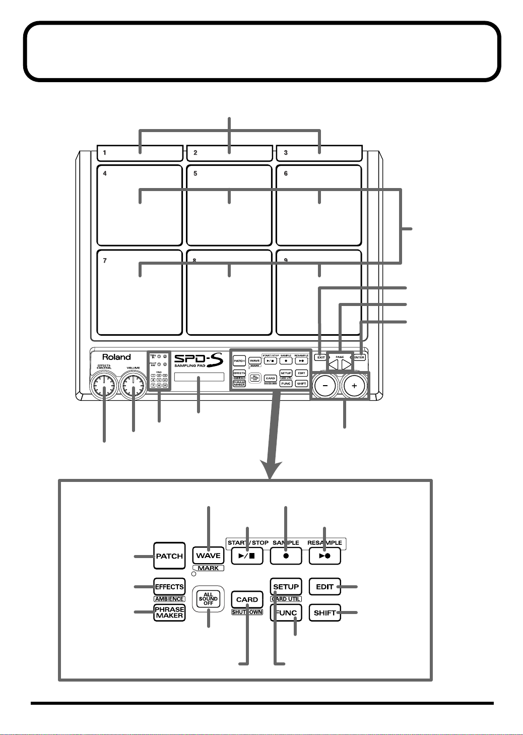
Panel Descriptions
1. PAD 1–3
2. PAD
4–9
20. EXIT button
21. PAGE buttons
22. ENTER button
5. PAD indicators
4. VOLUME knob
3. EFFECTS CONTROL kbob
7. PATCH button
8. EFFECTS button
AMBIENCE button
9. PHRASE
MAKER button
6. Display
10. WAVE button
MARK button
12. START/STOP
button
11. ALL SOUND
OFF button
15. CARD button
SHUTDOWN button
23. -/+ buttons
13. SAMPLE
button
14. RESAMPLE
button
17. EDIT button
19. SHIFT button
18. FUNC button
16. SETUP button
CARD UTIL button
14
Page 15
Panel Descriptions
Top Panel
1. PAD 1 to 3
To play these pads, strike them using the shoulder of the
stick.
2. PAD 4 to 9
Strike these pads with a stick to play them.
3. EFFECTS CONTROL knob
Controls the effects in real time. (p. 92)
4. VOLUME knob
Controls the output volume from the OUTPUT jacks. The
headphones volume can be controlled with the PHONES
LEVEL knob (37).
5. Pad indicators
Are lit when the sounds of their corresponding playing
surfaces are produced. When lit or flashing, they indicate
that the corresponding playing surfaces are selected during
editing.
Indicator
TRIG IN
FOOT SW Playing surfaces connected to the FOOT
PAD Pads on the SPD-S
6. Screen
Indicates patch names, wave names, parameter values, etc.
7. PATCH button
Press this button so it is lit to enter patch mode (p. 24,
p. 30).
8. EFFECTS button/AMBIENCE button
Press this button so it is lit to apply effects (p. 92).
Hold down [SHIFT] and press it to enable/disable the
ambience effects (p. 76).
9. PHRASE MAKER button
To use the Phrase Maker function (p. 63), press this button
for a moment so it is lit.
10. WAVE button/MARK button
Press this button so it is lit to enter wave mode (p. 41).
Hold down [SHIFT] and press it to use the marking
function (p. 48).
Playing surfaces
Playing surfaces connected to the TRIG IN
(1/2) jack (30)
SW (1/2) jack (29)
12. START/STOP button
Starts or stops sampling, resampling, or recording with the
Phrase Maker function. In wave mode, press this button to
reproduce the sound of the selected wave.
13. SAMPLE button
To carry out sampling (p. 52), press this button so it is lit.
14. RESAMPLE button
To carry out resampling (p. 59), press this button so it is lit.
15. CARD button/SHUTDOWN button
Press this button so it is lit to use a memory card.
Hold down [SHIFT] and press it for a moment to shut the
unit down (p. 22, p. 23).
16. SETUP button/CARD UTIL button
Press this button so it is lit to access the Setup Edit/Utilities
(p. 74).
Hold down [SHIFT] and press it to access the Card Utilities
(p. 67).
17. EDIT button
Press this button so it is lit to access the Patch Edit/Utilities
(p. 32, p. 33) or Wave Edit/Utilities (p. 43, p. 44).
18. FUNC button
For example, while this button is depressed, the remaining
memory capacity (time) is indicated. Depending on each
status, it produces different functions.
19. SHIFT button
Used in combination with other buttons (p. 90).
20. EXIT button
Returns to the screen at the previous layer.
21. PAGE buttons
Change the displayed item/parameter. Also used for
moving the cursor in a screen where you need to supply a
name.
22. ENTER button
Press this button when it is flashing to execute an
operation.
23. -/+ buttons
Change the patch number, wave number, or parameter
value.
Setup Guide
11. ALL SOUND OFF button
Stop all the sounds being produced.
15
Page 16
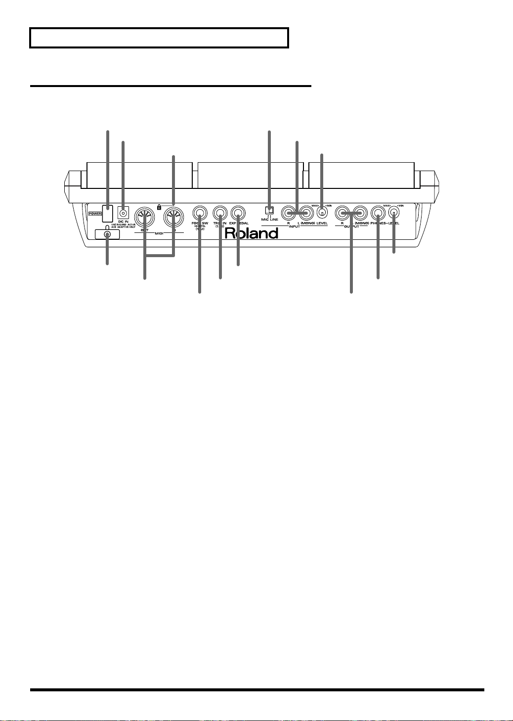
Panel Descriptions
Rear Panel
24. POWER switch
25. AC adaptor jack 33. INPUT jacks
26. Cord Hook
27. MIDI connectors
28. SECURITY LOCK
29. FOOT SW (1/2) jack
32. MIC/LINE switch
31. EXP PEDAL jack
30. TRIG IN (1/2) jack
34. INPUT LEVEL knob
37. PHONES LEVEL
knob
36. PHONES jack
35. OUTPUT jacks
16
Page 17
Panel Descriptions
24. POWER switch
Turns the unit on or off (p. 22).
25. AC adaptor jack
Accepts connection of the supplied AC adaptor (p. 20).
26. Cord hook
Anchors the AC adaptor cord (p. 20).
27. MIDI connectors (OUT, IN)
Connect MIDI devices.
28. Security Slot ( )
http://www.kensington.com/
29. FOOT SW (1/2) jack
Connect a foot switch (DP-2 or BOSS FS-5U sold
separately) or a hi-hat control pedal (FD-7 sold separately).
The foot switch and the control pedal can be used for
producing a sound or for changing a patch. To connect two
foot switches (FS-5U sold separately), use a dedicated cable
(PCS-31 sold separately).
35. OUTPUT jacks
Outputs sound signals. To output in mono, connect to the
L (MONO) jack (p. 20).
36. PHONES jack
Accepts connection of stereo headphones (p. 20). Sound
signals are output from the OUTPUT jacks even when
headphones are connected.
37. PHONES LEVEL knob
Controls the headphones volume. This knob is
independent of the VOLUME knob (4).
Setup Guide
30. TRIG IN (1/2) jack
Connect a separately sold pad, cymbal, kick trigger, or
acoustic drum trigger to the SPD-S (p. 80).
31. EXP PEDAL jack
Connect an expression pedal to control the effects.
Use only the specified expression pedal (EV-5; sold
separately). By connecting any other expression pedals,
you risk causing malfunction and/or damage to the unit.
32. MIC/LINE switch
Set this switch to MIC to connect a microphone to the
INPUT jacks. (p. 25, p. 53)
33. INPUT jacks
Connect an audio device or a microphone for sampling
(p. 20, p. 25, p. 53). To input a sound in mono, connect to
the L (MONO) jack.
34. INPUT LEVEL knob
Controls the input level of the signal from the device
connected to the INPUT jacks (p. 25, p. 26, p. 53, p. 54,
p. 56).
17
Page 18
Panel Descriptions
Side Panel
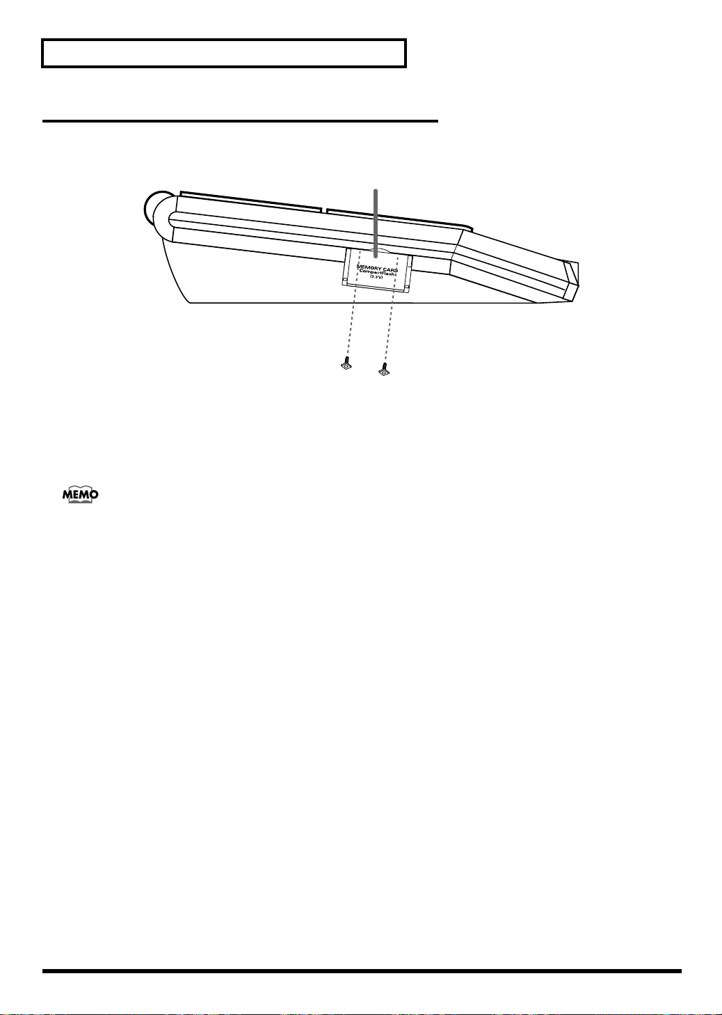
38. MEMORY CARD slot
Accepts a CompactFlash memory card (p. 67).
38. MEMORY CARD slot
Using the supplied hexagon wrench, you can attach the two security screws (supplied) in front of door to the memory card
slot. Once the screws have been secured in place, the door to the memory card slot cannot be opened, thus preventing theft of
the card.
18
Page 19
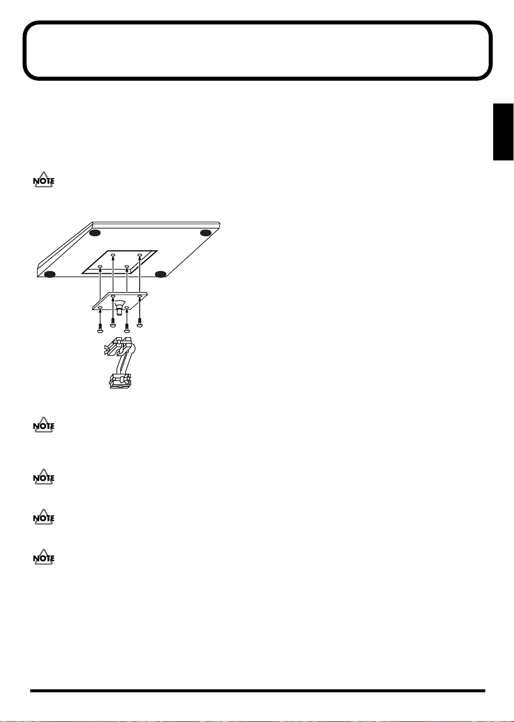
Mounting on a Stand
To mount the SPD-S on a cymbal stand or other type of stand, use a separately sold APC-33 all-purpose clamp set to attach the
stand holder. It can be attached to a pipe with a diameter of 10.5 to 30 mm.
Using a 4 mm wrench included with the all-purpose clamp (APC-33), remove the four screws from the SPD-S's bottom panel.
Use these removed screws to attach the stand holder of the APC-33 to the bottom panel of the SPD-S.
Do not use the screws included with the APC-33.
Setup Guide
When turning the unit upside-down, get a bunch of newspapers or magazines, and place them under the four corners or at both
ends to prevent damage to the buttons and controls. Also, you should try to orient the unit so no buttons or controls get damaged.
When turning the unit upside-down, handle with care to avoid dropping it, or allowing it to fall or tip over.
Make sure that the stand is installed in an appropriate place to ensure stability.
Do not mount the SPD-S on any stand that is insufficiently robust.
19
Page 20
Connecting External Devices
4
2
3
3
CD/MD Player,
Casette Tape Recorder
Roland
20
Page 21
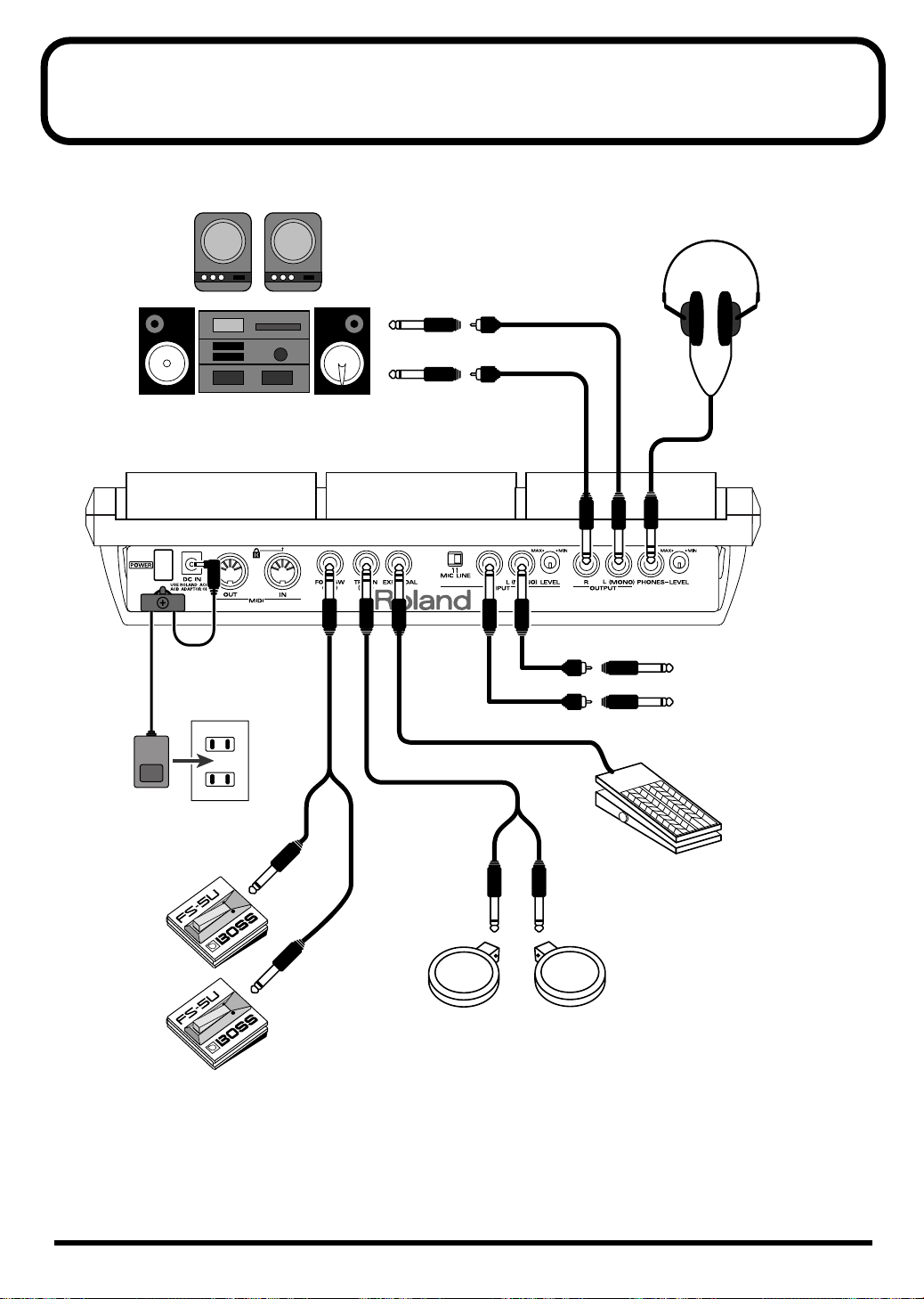
While referring to the illustration on the previous page, take the following steps:
1.
Before making a connection, power all the devices off.
Connecting External Devices
To prevent malfunction and/or damage to speakers or other devices, always turn down the volume, and turn off the power
on all devices before making any connections.
2.
Connect the supplied AC adaptor to the AC Adaptor jack.
To prevent the inadvertent disruption of power to your unit (should the plug be pulled out accidentally), and to avoid
applying undue stress to the AC adaptor jack, anchor the power cord using the cord hook, as shown on the previous page.
3.
Connect an audio system or an amplifier to the OUTPUT jacks. To use headphones, connect them to the
PHONES jack.
To sample (p. 25, p. 52), connect an input device (like a CD player or a microphone) to the INPUT jacks.
4.
Insert the plug of the AC adaptor into a power outlet.
Q: The volume level of the instrument connected to INPUT jacks is too low.
A: Could you be using a connection cable that contains a resistor?
Use a connection cable that does not contain a resistor.
Setup Guide
Howling could be produced depending on the location of microphones relative to speakers. This can be remedied by:
1. Changing the orientation of the microphone(s).
2. Relocating microphone(s) at a greater distance from speakers.
3. Lowering volume levels.
21
Page 22
Turning On/Off the Power
Turning On the Power
Once the connections have been completed (p. 20), turn on power to your various devices in the order specified. By turning on devices in the wrong
order, you risk causing malfunction and/or damage to speakers and other devices.
z
1.
Turn the VOLUME knob completely to the left to lower the volume to the minimum level.
2.
Turn down the volume control on the connected amp or audio system.
3.
Press the POWER button to turn on the power to the SPD-S.
This unit is equipped with a protection circuit. A brief interval (a few seconds) after power up is required before the unit will operate normally.
If you hit a pad when powering the unit on, the SPD-S produces poor responses to weak strikes.
4.
Turn on the power to the connected amp or audio system.
5.
Strike pads, and while listening to the sound, gradually bring up the VOLUME knob to adjust the volume
level.
Also raise the volume level of the connected amp or audio system to the appropriate level.
Turning Off the Power after the Shutdown Operation
Before turning off the power to the SPD-S, make sure to shut the unit down. Turning off the power before the shutdown operation is finished may
corrupt the data in the internal memory or the memory card.
1.
Select patch mode or wave mode.
Press [PATCH] to select patch mode, or press [WAVE] to select wave mode.
2.
Hold down [SHIFT] and press [CARD] for about two seconds to start the shutdown operation.
While the shutdown operation is in progress, a “shutdown..” indication is displayed. A “shutdown.. OK!” indication appears
when the shutdown operation is complete. Then you can turn off the power safely.
After a “shutdown.. OK!” indication appears, press [PATCH] to return to patch mode, or press [WAVE] to return to wave mode.
3.
Turn down the volume level of the SPD-S and the external devices connected to the SPD-S.
4.
Turn off the power to the external devices.
5.
Press the POWER button to turn off the power to the SPD-S.
22
Page 23
Inserting/Removing a Memory Card (CompactFlash)
Inserting a Memory Card
1.
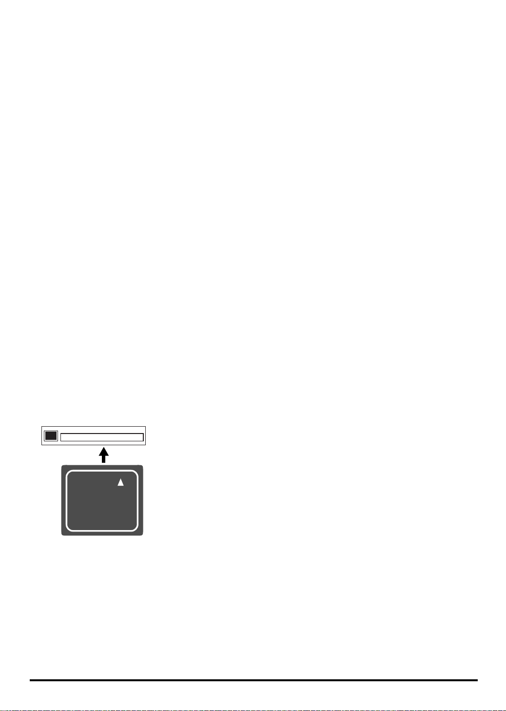
Open the card slot cover on the left side of the SPD-S, and insert a memory card.
A memory card can be inserted when either SPD-S’s power is on or off.
Carefully insert the CompactFlash all the way in-until it is firmly in place.
Removing a Memory Card after the Shutdown Operation
While the SPD-S’s power is on, make sure to take the shutdown operation before removing a memory card (CompactFlash). Removing it before
the shutdown operation is finished may corrupt the data in the internal memory or the memory card.
1.
Select patch mode or wave mode.
Setup Guide
Press [PATCH] to select patch mode, or press [WAVE] to select wave mode.
2.
Hold down [SHIFT] and press [CARD] for about two seconds to start the shutdown operation.
While the shutdown operation is in progress, a “shutdown..” indication is displayed. A “shutdown.. OK!” indication appears
when the shutdown operation is complete. Then you can remove the memory card safely.
After a “shutdown.. OK!” indication appears, press [PATCH] to return to patch mode, or press [WAVE] to return to wave mode.
After finishing the shutdown operation, SPD-S cannot detect a memory card in the card slot. If you pull out the card from the card slot and
insert it again, then it is detected.
3.
Open the card slot cover and push an eject button beside the card slot. Then, pull out the card with your
fingers.
After removing the memory card, SPD-S returns to patch mode or wave mode.
23
Page 24
Quick Start
Making a Performance
Take the following steps:
1
Follow the steps explained on p. 20 to connect external devices to the
SPD-S.
2
Follow the steps in “Turning On the Power” (p. 22) to power the SPD-S
on.
3
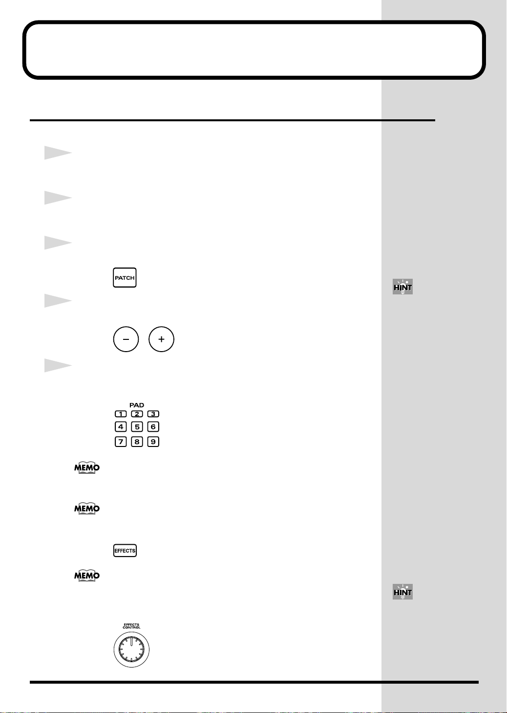
Press [PATCH] so it is lit. The SPD-S enters patch mode.
4
To select a patch, press [-]/[+] to change the patch number.
5
Hit the nine pads on the SPD-S with your sticks to play something.
The pad indicators of pads you hit will light.
Hit pads 1 to 3 using the shoulder portion of the sticks.
To enable the effects, press [EFFECTS] so it is lit. To disable the effects, press
[EFFECTS] so it is unlit.
If you hold down [SHIFT] and
press [-]/[+], you can change
the patch number in steps of
10. If you hold down [+] and
press [-], or hold down [-] and
press [+], the patch number
changes quickly.
24
To control the effects, turn the EFFECTS CONTROL knob to the left or right. Turning
the knob to the right increases the difference. This operation is active while
[EFFECTS] is lit.
If you hold down [SHIFT] and
press [EXIT], the changes
you’ve made with the knob are
cancelled.
Page 25
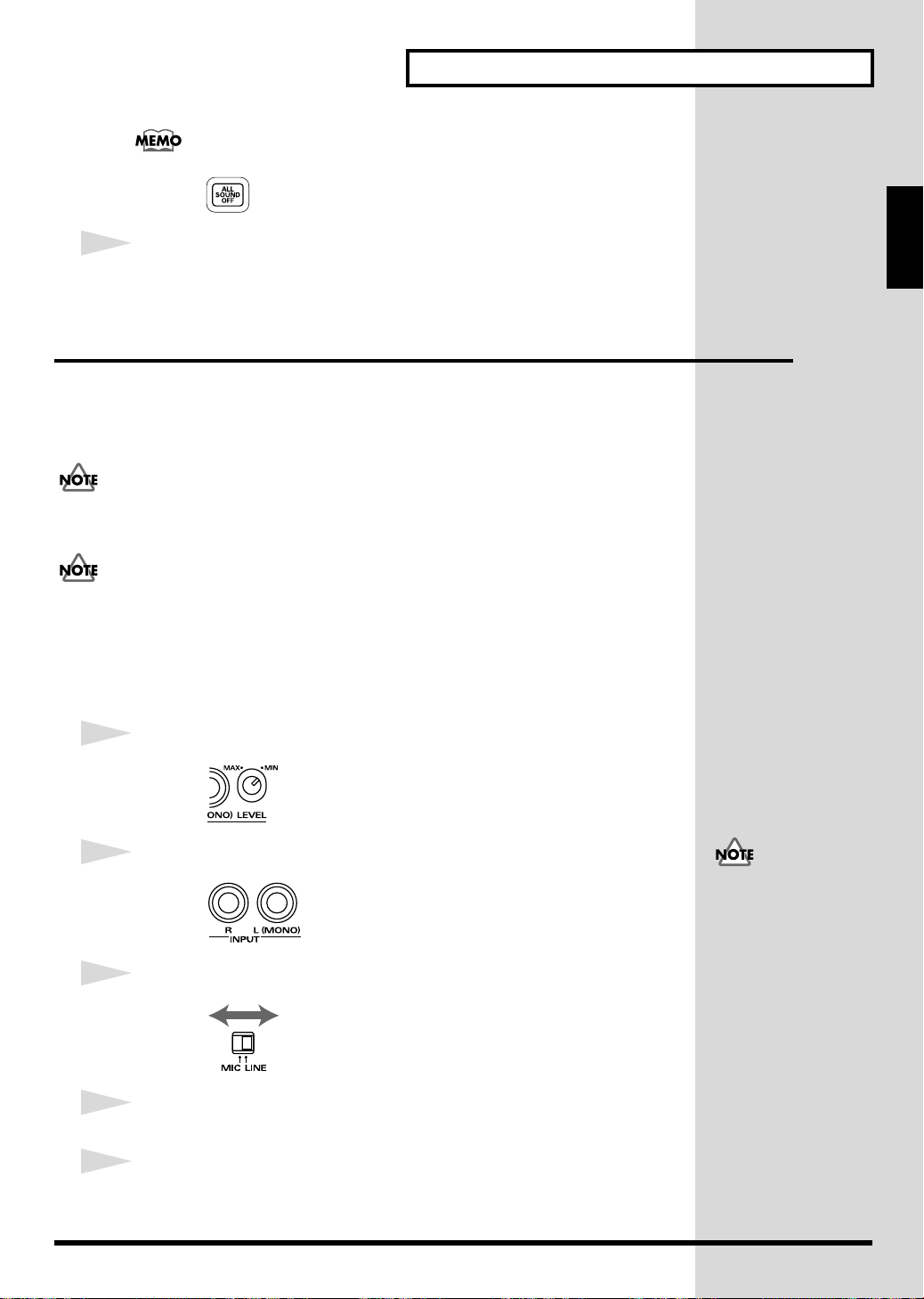
If you press [ALL SOUND OFF], all sounds being produced are stopped.
6
After your performance, follow the steps in “Turning Off the Power
after the Shutdown Operation” (p. 22) to power the SPD-S off.
Sampling
The SPD-S allows you to load (sample) your favorite sounds, then play them.
The following guides you through the process of connecting a CD player,
sampling a sound from the accompanying CD, and playing it back.
Unauthorized recording (sampling) of any audio work made by any third parties is prohibited by law, unless it
is limited to special circumstances, such as private, personal enjoyment. Do not record illegally.
Quick Start
Setup Guide
Roland Corporation assumes no responsibility or liability for legal penalties or claims made by copyright
holders as a result of any illegal recordings made using any Roland product.
■
Before Sampling
Take the following steps before sampling:
1
Turn the INPUT LEVEL knob on the rear panel to MIN.
2
Connect a CD player to the INPUT jacks on the rear panel.
3
Set the MIC/LINE switch on the rear panel to LINE.
To prevent malfunction and/
or damage to speakers or other
devices, always turn down the
volume, and turn off the
power on all devices before
making any connections.
4
Power up the CD player.
5
Follow the steps in “Turning On the Power” (p. 22) to power the SPD-S
on.
25
Page 26
Quick Start
■
Sampling
1
fig.PatchButton
2
3
fig.SampleButton
4
fig.SelectDestPad.eps
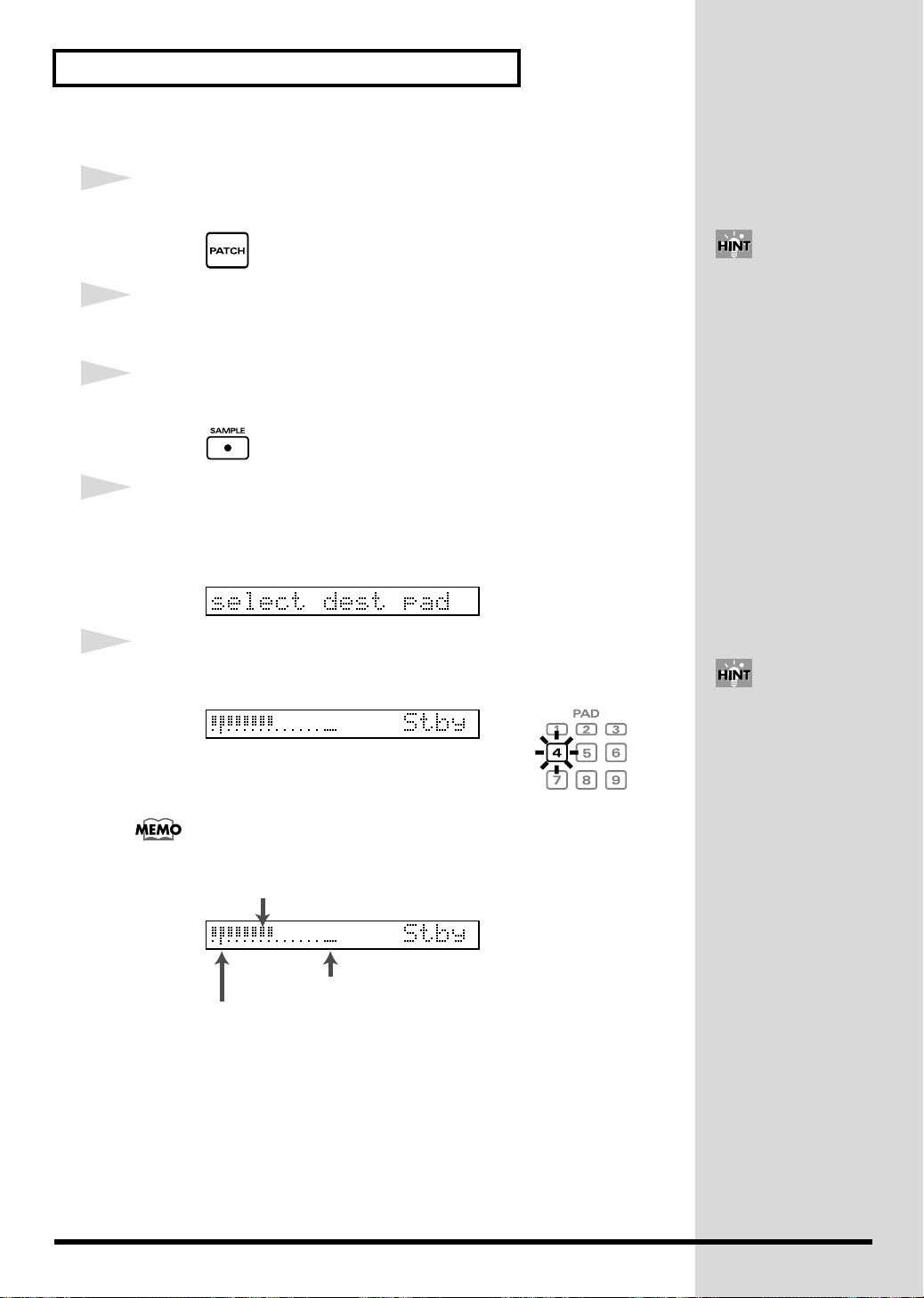
Press [PATCH] so you are in patch mode.
Press [-]/[+] to select the patch that name is “New Patch.”
Press [SAMPLE].
The screen displays “select dest pad.” Try to sample a sound onto
PAD 4 in this tutorial. So, hit the playing surface of the PAD 4. If you
need to select a pad again, press [EXIT] to return to patch mode.
If you hold down [SHIFT] and
press [-]/[+], you can change
the patch number in steps of
10. If you hold down [+] and
press [-], or hold down [-] and
press [+], the patch number
changes quickly.
5
A “Stby” (Standby) message is displayed and the indicator of PAD 4
lights. Play back the connected CD player and control the input level.
The sound input from INPUT jacks can be heard through the SPD-S.
fig.Stby_e
Turn the INPUT LEVEL knob on the rear panel with your eye on the level
meter to maximize the input level within the range in which the excess level
indication remains unlit.
Input signal level meter
Excess level indication
StartLvl (Start Level) indication
While [FUNC] is being
depressed in Steps 5–6, the
remaining time for sampling
(“Remain”) is displayed.
(p. 58)
26
Page 27
6
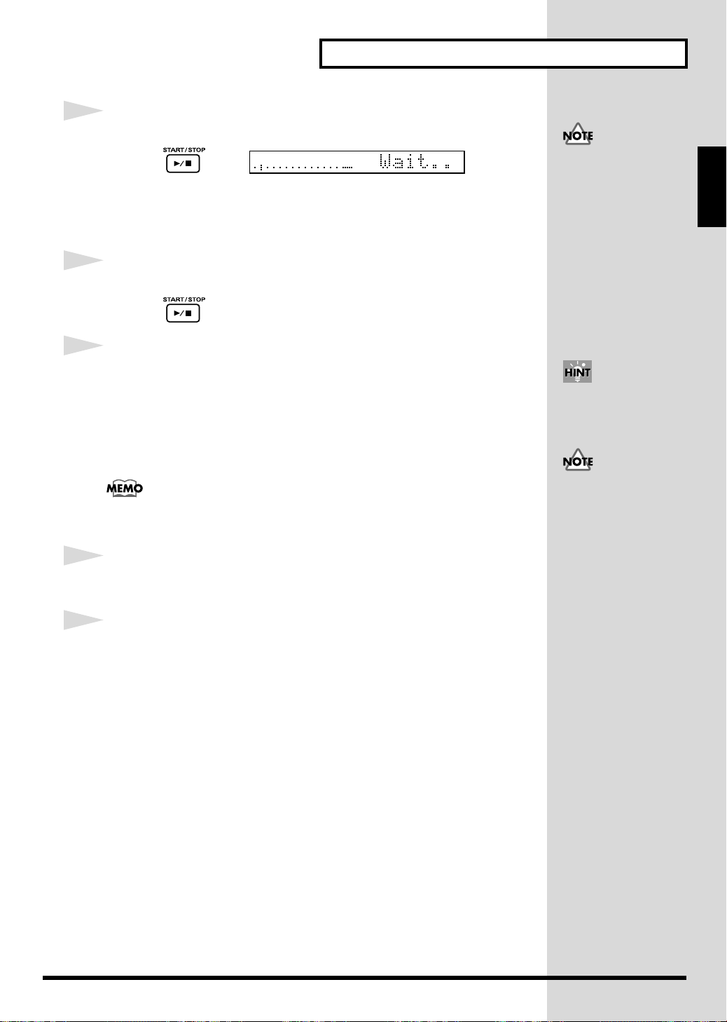
Press [START/STOP] to start sampling.
A “Wait..” message appears and the SPD-S enters the standby state. Start
playback of the CD player, then sampling begins automatically. A “Rec”
message is displayed while sampling is in progress.
7
Press [START/STOP] to finish sampling.
8
A “write?” message is displayed. Assign a name to the wave. Press the
PAGE buttons to move the cursor under the name and press [-]/[+] to
change the character at the cursor position. When the name is
complete, press [ENTER] to save it.
A “now writing..” message appears; it shows that a wave is being saved.
Quick Start
Do not power the SPD-S off
while sampling is in progress.
Setup Guide
If you press [START/STOP] or
hit a relevant playing surface,
you can check the sampled
sound.
If you do not want to save the wave, press [EXIT], and you will return to the ‘Stby”
(Standby) screen in Step 5.
9
After saving the wave, you will return to patch mode. If you hit the
playing surface of PAD 4, you can check the sampled sound.
10
Turn off the power to the SPD-S according to the steps of “Turning Off
the Power after the Shutdown Operation” (p. 22).
Do not power the SPD-S off
while saving a wave.
27
Page 28

28
Page 29

Advanced Use
29
Page 30
Chapter 1 Making a Performance/
Creating a Patch
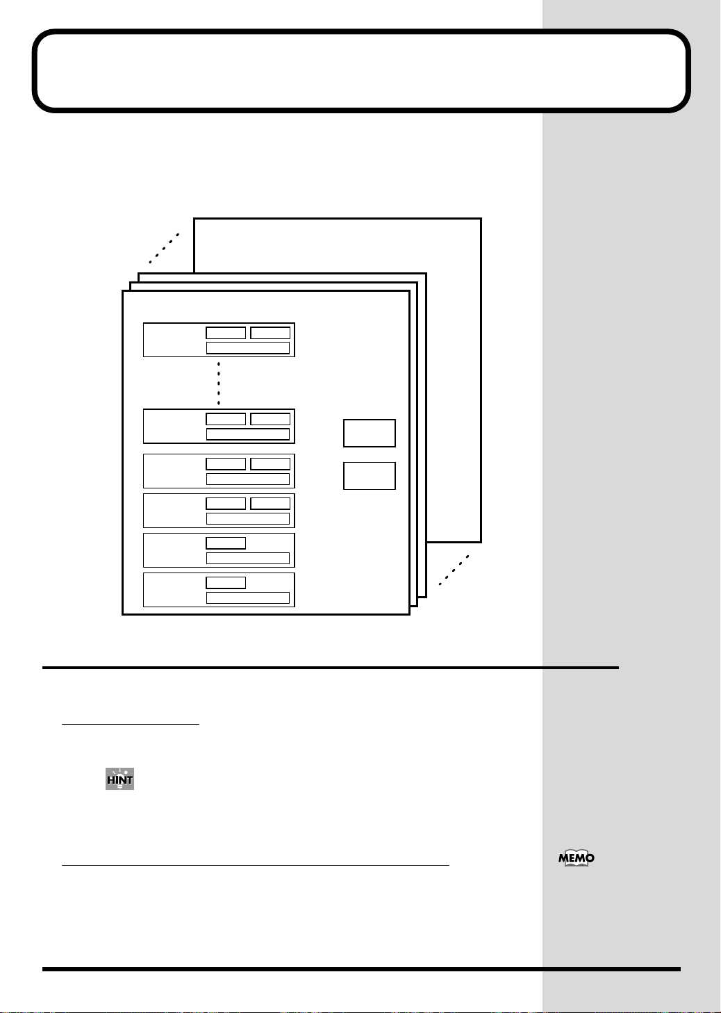
The patch mode is for giving a performance. A patch is a combination of
sounds assigned to different playing surfaces and effect settings. The internal
memory can store 128 patches. No patch can be stored on any memory card.
fig.gainen
128
003
002
001
Patch 001
PAD 1
WAVE A
PAD CONTROL
WAVE B
PAD 9
TRIG IN 1
TRIG IN 2
FOOT SW 1
FOOT SW 2
Patch Mode
To enter patch mode, press [PATCH] so it is
Selecting a patch
Press [-]/[+] to change the patch number.
If you hold down [SHIFT] and press [-]/[+], you can change the patch number in steps of 10. If
you hold down [+] and press [-], or hold down [-] and press [+], the patch number changes
quickly.
WAVE A
PAD CONTROL
WAVE A
PAD CONTROL
WAVE A
PAD CONTROL
WAVE A
PAD CONTROL
WAVE A
PAD CONTROL
WAVE B
WAVE B
WAVE B
PATCH
COMMON
EFFECTS
lit
.
Making sure of the memory card (CompactFlash)
When the selected patch uses a wave stored on a card,
without the CompactFlash card inserted in the card slot of the SPD-S. In this
case, the wave sound is not reproduced.
30
[CARD] flashes
If you press [CARD] while it is
flashing, its light goes out
temporarily.
Page 31

Chapter 1 Making a Performance/ Creating a Patch
Locking the buttons
You can lock (disable) the buttons so that a performance cannot be
interrupted if a button like [SAMPLE] is pressed by mistake while the
performance is in progress. Keep pressing [FUNC] for a while to lock the
buttons; “
while again to unlock the buttons; “
lock
” will be displayed in the screen. Keep pressing [FUNC] for a
unlock
” will be displayed.
If you press a locked button, a
“lock!” indication appears.
Enabling/disabling
To turn ambience ON, hold down [SHIFT] and press [EFFECTS], so that
“
Ambience ON
To turn ambience
“
Ambience OFF
Ambience cannot be individually enabled or disabled for different patches.
ambience
” appears in the display.
OFF
, hold down [SHIFT] and press [EFFECTS], so that
” appears in the display.
Enabling/disabling effects
To
enable
effects, press [EFFECTS] so it is lit.
To
disable
effects, press [EFFECTS] so it is not lighted.
Controlling effects
While hitting playing surfaces for a performance, turn the EFFECTS
CONTROL knob, depress the expression pedal or control the strength of your
strikes to make change to effects.
Stopping all sounds produced (ALL SOUND OFF)
Press [ALL SOUND OFF] to stop all sounds being produced.
For example, if Trigger (in WAVE SETUP in Wave Edit -> p. 46) is set to
SHOT for a long wave, sound reproduction is unstoppable midstream. In this
case, you can stop the sound by pressing [ALL SOUND OFF].
For details on ambience, see p.
76.
For details on effects, see p. 92.
If you hold down [SHIFT] and
press [EXIT], changes made to
patch effects are cancelled.
Controlling effects are valid
when [EFFECTS] is lit.
Chapter 1
■
Notes on Giving a Performance
Number of waves that can be reproduced simultaneously
The SPD-S can reproduce a maximum of eight voices simultaneously. A wave
for which Mode (in Sampling -> p. 58) is set to STEREO or Grade (in
Sampling ->p. 58) is set to FINE has two voices. A wave in STEREO and in
FINE grade has four voices.
If you try to reproduce more than eight voices, the wave of the pad that was
hit earlier is stopped to give preference to reproducing the wave of the pad
that was struck later. In this case, reproduction of a wave for which Type (p.
45) is set to SINGLE is discontinued earlier than a PHRASE-type wave.
31
Page 32

Chapter 1 Making a Performance/ Creating a Patch
b
Basic Operations for Patch Edit
This section describes the steps for setting a patch. Patch settings are made
using Patch Edit.
1
Press [PATCH] so you are in patch mode.
2
Press [-]/[+] to select a patch.
3
Press [EDIT] to go into Patch Edit.
[EDIT] lights at this time.
4
Press the PAGE buttons to select an item to be edited from those listed
below, and then press [ENTER].
To select another item after pressing [ENTER], press [EXIT].
For details on each item, see its reference page.
•
WAVE A
•
WAVE B
•
PAD CONTROL
•
EFFECTS
•
PATCH COMMON
Listed below are patch utilities. See p. 33.
• PAD COPY
• PAD EXCHANGE
• PAD INIT (Pad Initialize)
• PATCH COPY
• PATCH EXCHANGE
• PATCH INIT (Patch Initialize)
-> p. 34
-> p. 34
-> p. 36
-> p. 37
-> p. 37
If you hold down [SHIFT] and
press [-]/[+], you can change
the patch number in steps of
10. If you hold down [+] and
press [-], or hold down [-] and
press [+], the patch number
changes quickly.
If there are any selectable
items, PAGE buttons ([<], [>]
or both) are lit.
When it is necessary to press
[ENTER], it is flashing.
5
Press the PAGE buttons to change the parameter for the item.
To change the individual settings for different playing surfaces, hit a playing
surface (such as a pad on the SPD-S, an external pad, or a foot switch) for
which the settings are to be changed to select it. A flashing pad indicator
indicates that the corresponding playing surface is selected.
6
While hitting the playing surface for monitoring the sound, press [-]/[+]
to change the parameter value.
7
Press [EXIT] and then repeat Steps 4 to 6 to continue Patch Edit
operations. Press [PATCH] to finish Patch Edit.
The SPD-S saves the settings (with “now writing..” indicated) and then
returns to the patch mode.
32
While editing you can also
choose among pads/sounds
y pressing a PAGE button
while holding down [SHIFT].
If you hold down [SHIFT] and
press [FUNC], the parameter is
reset to its initial value.
Page 33

Patch Utilities
When changing any item on the following patch utilities, see their respective
reference pages.
Chapter 1 Making a Performance/ Creating a Patch
* You can select the items listed below in Step 4 (p. 32) in “Basic Operations for Patch
Edit.” However, they are different in character from Patch Edit. To take the
subsequent steps for these items, follow the steps described on their respective
reference pages.
•
PAD COPY
•
PAD EXCHANGE
•
PAD INIT
•
PATCH COPY
•
PATCH EXCHANGE
•
PATCH INIT
-> p. 38
-> p. 38
(Pad Initialize) -> p. 39
-> p. 39
-> p. 39
(Patch Initialize) -> p. 40
Steps 1 to 4 in “Basic
Operations for Patch Edit” are
identical to the steps for
operation of patch utilities.
Chapter 1
33
Page 34

Chapter 1 Making a performance/Creating a patch
Patch Edit Parameters
These parameters allow you to select the sounds that will be triggered by pads on or connected to the SPD-S (or foot switch).
WAVE A
Select a wave to be assigned to a pad (Press EDIT). Two waves, A and B, can be assigned to any pad. Only Wave A can be
assigned to the foot switch. This is for configuring wave A.
Hit the pad or press the PAGE buttons while holding down [SHIFT] to choose what you are editing. Pad indicators light up to
indicate what pad/trigger you are working on.
Setting up: Press PAGE buttons to change the parameter and press [-]/[+] to change the value.
Parameter Value Descriptions
A
(Wave)
A Level 0–127 Set the volume of wave A.
A Pan L15–CENTER–R15,
I
000 (OFF),
I
001–399,
C
001–500
RANDOM
Specify the wave number (sound) assigned to the wave A position.
I
000 (OFF): Selected when you want no sound to be produced
I
001–399: Internal memory
C
001–500: Memory card
* By pressing [CARD], you can select the top number of the internal memory or of the
memory card.
Set the pan position (left-right balance) of wave A. If set to RANDOM, the pan position
varies each time the sound is reproduced.
If you change the value in Level or Pan during sound production, the sound is stopped.
If you hold down [SHIFT] and press [FUNC], the parameter is reset to its initial value.
If you hold down [SHIFT] and press [ENTER], the parameter is copied to all other pads/triggers.
WAVE B
Select a wave to be assigned to a pad (Press EDIT). This is for configuring wave B.
Hit the pad or press the PAGE buttons while holding down [SHIFT] to choose what you are editing. Pad indicators light up to
indicate what pad/trigger you are working on.
Wave B can NOT be assigned to any foot switch.
Setting up: Press PAGE buttons to change the parameter and press [-]/[+] to change the value.
Parameter Value Descriptions
Wave SW
(Wave Switch)
OFF,
VELO,
FOOTSW
Determines HOW waves A and B will sound.
OFF: Wave B is not triggered.
VELO: The sound to be reproduced, either wave A or B, is determined by the velocity (strike
force). The threshold level is specified with VeloSWPoint, below.
FOOTSW: You can use a foot switch to change between wave A and wave B. When you press
the switch, wave B is triggered. Otherwise, wave A is reproduced. (FOOT SW in
CONTROL SW in SETUP must be set to WAVE SW. -> p. 79)
34
Page 35

Chapter 1 Making a performance/Creating a patch
When Wave SW is set to anything but OFF, the following screens for selection of an item for Waves A and B are displayed:
When Wave SW is not set to OFF, set the following parameters as well.
Parameter Value Descriptions
B
(Wave)
B Level 0–127 Set the volume of wave B.
B Pan L15–CENTER–R15,
If you change the value in Level or Pan during sound production, the sound is stopped.
If you press [FUNC] while editing the three parameters above, the screen is switched between the wave A and B screens.
When Wave SW is set to VELO, set the following parameter as well.
Parameter
VeloSWPoint
(Velocity
Switch Point)
I
000 (OFF),
I
001–399,
C
001–500
RANDOM
Value Descriptions
2–127 Set the threshold level. When the velocity is equivalent to or above this value, wave B is reproduced.
* The velocity here refers to the value of the strike force expressed on a scale of 1 to 127.
Specify the wave number assigned to wave B.
I
000 (OFF): Selected when you want no sound to be produced
I
001–399: Internal memory
C
001–500: Memory card
* By pressing [CARD], you can select the top number of the internal memory or of the
memory card.
Set the pan position (left-right balance) of wave B. If set to RANDOM, the pan position
varies each time the sound is reproduced.
Chapter 1
If you hold down [SHIFT] and press [FUNC], the parameter is reset to its initial value.
If you hold down [SHIFT] and press [ENTER], the parameter is copied to all other pads/triggers.
35
Page 36

Chapter 1 Making a performance/Creating a patch
PAD CONTROL
Configures pad/trigger parameters.
Configurations can be set for individual pads/triggers. Hold down [SHIFT] and press the PAGE buttons or hit a pad/trigger to
change the pad/trigger. A flashing pad indicator shows that the corresponding pad/trigger is selected.
Set the following parameters. Press PAGE buttons to change the parameter and press [-]/[+] to change values.
Parameter Value Descriptions
Dynamics OFF, ON Set it to ON to change the volume according to playing velocity. When it is set to OFF, the
sound is produced at a constant volume.
Effects SW
(Effects
Switch)
DynamicAtck
(Dynamic Attack)
Mute Group OFF, 1–9 Pads/triggers that are assigned the same number form a mute group. Within a mute group,
Tempo Sync OFF, ON When it is set to ON, the tempo of the sound assigned to the pad is synchronized with the
Note# OFF,
Gate Time 0.1 s–8.0 s Allows you to determine the length (gate time) of the notes that will be transmitted from the
OFF, ON,
VELO
OFF, 1–3 The start or attack of the sound is reduced when the pad/trigger is hit softly and increases
0(C-)–127(G9)
This determines if the sound on any particular pad is sent to the effects. When it is set to VE-
LO, effect parameters (those specified in VELO in individual effect types) are controlled by
the strike intensity.
* The pad indicators will light when this parameter is set to ON or VELO.
with playing velocity. It is suitable for sounds like percussion.
* If the start point (p. 47) is not adequately defined for a wave, no satisfactory effect is pro-
duced.
the sounds cancel out one another, and only the sound from the pad/trigger that’s struck
last is reproduced.
* The lit pad indicators show that their corresponding pads/triggers belong to the same
mute group.
sync tempo of the patch (See Sync Tempo in PATCH COMMON -> p. 37).
* The pad indicator is lit when this parameter is set to ON for the corresponding pad/trig-
ger.
* If you hold down [FUNC] and press [-]/[+], you can change Sync Tempo (in PATCH
COMMON -> p. 37).
Determines the note number assigned to each pad, which will be transmitted from the MIDI
OUT connector. See the table below for initial values.
* When it is set to OFF, no note message is sent or received via MIDI.
* If the same note number is assigned to more than one pads, the wave assigned to the
pad/trigger with the lowest number (see the table below) will sound when the SPD-S
receives note message with the note number concerned. A “*” symbol is indicated on the
screen for playing surfaces with assigned sounds that are not reproduced when note
message is received.
MIDI OUT connector, on an individual pad basis. The value can be changed in steps of 0.1
second.
Volume variation cannot be activated with a foot switch.
If you hold down [SHIFT] and press [FUNC], the parameter is reset to its initial value.
If you hold down [SHIFT] and press [ENTER], the parameter is copied to all other pads/triggers.
Initial values of Note#
Number
1
2 PAD 2 61 (C#4) 9 PAD 9 68 (G#4)
3 PAD 3 62 (D4) 10 TRIG IN 1 69 (A4)
4 PAD 4 63 (D#4) 11 TRIG IN 2 70 (A#4)
5 PAD 5 64 (E4) 12 FOOT SW 1 71 (B4)
Playing Surface Initial Value Number Playing Surface Initial Value
PAD 1 60 (C4) 8 PAD 8 67 (G4)
36
Page 37

Chapter 1 Making a performance/Creating a patch
Number Playing Surface Initial Value Number Playing Surface Initial Value
6 PAD 6 65(F4) 13 FOOT SW 2 72 (C5)
7 PAD 7 66(F#4)
Notes on Tempo Sync
• Tempo Sync is not applicable to waves of which:
1.
Type (in WAVE SETUP in Wave Edit -> p. 45) is SINGLE.
2.
Tempo is not within the range from 20 to 260 although Type is PHRASE.
In this event, "---" is indicated for Tempo on the screens on Beat (in WAVE SETUP in Wave Edit -> p. 46) and on Meas (in
WAVE SETUP in Wave Edit -> p. 46).
3.
Reverse (in WAVE SETUP in Wave Edit -> p. 46) is set to ON.
• The wave tempo is variable within the range from 50% to 130%. If Sync Tempo (in PATCH COMMON -> p. 37) exceeds this
range, the wave tempo is doubled or halved so that it can stay within the range.
• When Tempo Sync is applied, there may be some outstanding noise.
EFFECTS
How to set up the EFFECTS.
Press PAGE buttons to change the parameter and press [-]/[+] to change the value.
For details on parameters of effects, see “Effect List” (p. 92).
Chapter 1
PATCH COMMON
Set the parameters common to the whole patch.
Set the following parameters. Press PAGE buttons to change the parameter and press [-]/[+] to change the value.
Parameter
Sync Tempo
Patch Level 0–127 Specify the volume of the patch.
Name Patch name Give a name to the patch. A name can have a maximum of eight characters. Press PAGE buttons
Value Descriptions
=20–260
Set the sync tempo. When tempo sync is on (with Tempo Sync in PAD CONTROL set to ON ->
p. 36), the tempo of the waves assigned to the pads is synchronized with this tempo.
* The pad indicator is lit when Tempo Sync in PAD CONTROL is set to ON for the correspond-
ing pad/trigger.
* If you hold down [SHIFT] and hit a pad, the value of Tempo Sync in PAD CONTROL is
switched (between ON and OFF).
* For notes on Tempo Sync, see the top of the page.
* You can also define the tempo by controlling the intervals at which you hit a pad or depress
a foot switch. (Tap Tempo: Ctrl SW in CONTROL SW in Setup Edit -> p. 79)
to move the cursor below the name and press [-]/[+] to change the character at the cursor.
* If you hold down [+] and press [-], or hold down [-] and press [+], the character changes
quickly.
* Hold down [SHIFT] and press [>] to insert a character, or hold down [SHIFT] and press [<]
to delete a character.
* Press [FUNC] to switch a letter between uppercase and lowercase.
* If you hold down [SHIFT] and press [+], the character is changed in the order of “A”, “a”,
“0,” “!” and a space character. If you hold down [SHIFT] and press [-], the character is
changed in the reverse order.
If you hold down [SHIFT] and press [FUNC], the parameter is reset to its initial value (except on the “Name” screen).
37
Page 38

Chapter 1 Making a performance/Creating a patch
Patch Utilities Parameters
This section describes the steps for copying, exchanging and initializing patches and/or pad parameters.
PAD COPY
This copies all parameters from one pad to another.
1.
Set the following parameters.
Press PAGE buttons to change the parameter and press [-]/[+] to change the value.
Parameter Value Descriptions
Src
(Source)
Dst
(Destination)
2.
Press [>] to display “copy pad, sure?” Press [ENTER] to execute the copying, or press [<] to return to
Step 1.
While copying is in progress, “now processing..” is displayed. Upon completion of the procedure, “complete!” is displayed,
and you’re returned to the Patch mode.
*MIDI note number and gate time parameters are not copied.
PAD 1–9,
TRIG IN 1–2,
FOOT SW 1–2
PAD 1–9,
TRIG IN 1–2,
FOOT SW 1–2
Hit a pad to choose the copy source. Or, you can press [-]/[+] to select it.
* You can check which pad is specified by noticing which pad indicator is flashing, or
by viewing the display.
* Hold down [FUNC] and press [-]/[+] to change the patch to be copied from.
Hit a pad to choose the copy destination. Or, you can press [-]/[+] to select it.
* You can check which pad is specified by noticing which pad indicator is flashing, or
by viewing the display.
* Hold down [FUNC] and press [-]/[+] to change the patch to be copied to.
PAD EXCHANGE
This exchanges all parameters between one pad/trigger and another.
1.
Set the following parameters.
Press PAGE buttons to change the parameter and press [-]/[+] to change the value.
Parameter
Src
(Source)
Dst
(Destination)
2.
Press [>] to display “exchg pad, sure?” Press [ENTER] to execute the exchange, or press [<] to return to
Step 1.
While exchanging is in progress, “now processing..” is displayed. Upon completion of the procedure, “complete!” is
displayed, and you’re returned to the Patch mode.
*MIDI note number and gate time parameters are not exchanged.
Value Descriptions
PAD 1–9,
TRIG IN 1–2,
FOOT SW 1–2
PAD 1–9,
TRIG IN 1–2,
FOOT SW 1–2
Hit a pad to choose the exchange source. Or, press [-]/[+] to change it.
* You can check which pad is specified by noticing which pad indicator is flashing, or
by viewing the display.
* Hold down [FUNC] and press [-]/[+] to change the patch to be exchanged from.
Hit a pad to choose the exchange destination. Or, press [-]/[+] to change it.
* You can check which pad is specified by noticing which pad indicator is flashing, or
by viewing the display.
* Hold down [FUNC] and press [-]/[+] to change the patch at the destination of the ex-
change.
38
Page 39

Chapter 1 Making a performance/Creating a patch
PAD INIT (Pad Initialize)
Initialize (factory reset) the parameters for a pad/trigger.
The wave number for wave A is not changed.
1.
Set the following parameter.
Press PAGE buttons to change the parameter and press [-]/[+] to change the value.
Parameter Value Descriptions
Init
(Initialize)
2.
Press [>] to display “init pad, sure?” Press [ENTER] to initialize the parameters for the playing surface,
PAD 1–9,
TRIG IN 1–2,
FOOT SW 1–2
Hit a pad/trigger the one to be initialized. Or, press [-]/[+] to change it.
* You can check which pad is specified by noticing which pad indicator is flashing, or
by viewing the display.
or press [<] to return to Step 1.
While initializing is in progress, “now processing..” is displayed. Upon completion of the procedure, “complete!” is
displayed, and you’re returned to the Patch mode.
PATCH COPY
Copy a patch to another.
Chapter 1
1.
Set the following parameters.
Press PAGE buttons to change the parameter and press [-]/[+] to change the value.
Parameter
Src (Source)
Dst (Destination) 1–128 Specify the copy-destination patch number.
2.
Press [>] to display “copy patch, sure?” Press [ENTER] to copy the patch, or press [<] to return to Step
Value Descriptions
1–128 Specify the copy-source patch number.
1.
While copying is in progress, “now processing..” is displayed. Upon completion of the procedure, “complete!” is displayed,
and you’re returned to the Patch mode.
PATCH EXCHANGE
Exchanges a patch with another. (Helpful for putting your patches in the desired order.)
1.
Set the following parameters.
Press PAGE buttons to change the parameter and press [-]/[+] to change the value.
Parameter
Src (Source)
Dst (Destination) 1–128 Specify the patch number that is to be the second partner in the exchange.
2.
Press [>] to display “excg patch, sure?” Press [ENTER] to execute the exchange, or press [<] to return
to Step 1.
While exchanging is in progress, “now processing..” is displayed. Upon completion of the procedure, “complete!” is
displayed, and you’re returned to the Patch mode.
Value Descriptions
1–128 Specify the patch number that is to be the first partner in the exchange.
39
Page 40

Chapter 1 Making a performance/Creating a patch
PATCH INIT (Patch Initialize)
Initializes the parameters for a patch.
1.
A “[>] to init.” indication appears. Press [>].
2.
“init patch, sure?” appears. Press [ENTER] to reset the parameters for the patch to their respective
initial values.
While initializing is in progress, “now processing..” is displayed. Upon completion of the procedure, “complete!” is
displayed, and you’re returned to the Patch mode.
40
Page 41

Chapter 2 Wave Editing
Wave
A wave is a combination of a "sound material" created by sampling a sound
of musical instruments, a voice or a performance and the settings at sound
reproduction. A wave is assigned to a playing surface in patch mode so that
it can be used in an actual performance.
The SPD-S stores a maximum of 399 waves in its internal memory and 500
waves on a memory card.
Wave Mode
To enter wave mode, press [WAVE] so it is
Wave mode screen
fig.wavemode.eps
Icon
I
C
Icon
Mode (p. 58) Grade (p. 58)
No icon MONO LONG
Description
A wave stored in internal memory
A wave stored on the memory card
Description
A new (empty) wave
A non-empty wave
STEREO STANDARD
Selecting a wave
Press [-]/[+] to change the wave number.
lit
.
If "I000 OFF" is selected, no
sound is produced. This wave
is designed so it can be
assigned in patch mode to
playing surfaces that you want
to remain silent.
A wave of which Mode (p. 58)
is STEREO or Grade (p. 58) is
FINE has two voices. A wave
in STEREO and in the FINE
FINE
grade has four voices.
Chapter 2
If you hold down [SHIFT] and press [-]/[+], you can change the wave number in steps of 10. If
you hold down [+] and press [-], or hold down [-] and press [+], the wave number changes
quickly.
Checking the wave tempo and the wave length (time)
The tempo and the length (time) of a wave are displayed if you continue
pressing [FUNC]. The tempo is shown in the format of “ = value” (or “---”
when no value is set) and the length in minutes (m) and seconds (s).
fig.WaveFunc.eps
If you press [START/STOP] or
hit the playing surface, the
wave currently selected is
played back. By pressing [ALL
SOUND OFF], you can stop all
sounds from being
reproduced.
41
Page 42

Chapter 2 Wave Editing
Jumping to the top of internal memory or the memory
card
Press [CARD] to alternately jump to the top wave number in the internal
memory and to that of the memory card.
Jumping to a new (empty) wave number
Hold down [SHIFT] and press [FUNC] to jump to a new (empty) wave
number.
Enabling/disabling
To turn ambience ON, hold down [SHIFT] and press [EFFECTS], so that
“
Ambience ON
To turn ambience
“
Ambience OFF
Ambience cannot be individually enabled or disabled for different patches.
Effects are unavailable in wave mode. [EFFECTS] is unlit.
ambience
” appears in the display.
OFF
, hold down [SHIFT] and press [EFFECTS], so that
” appears in the display.
For details on ambience, see p.
76.
42
Page 43

Basic Operations for Wave Edit
This section describes the steps for setting wave parameters. Wave settings
are made using Wave Edit.
Chapter 2 Wave Editing
1
Press [WAVE] so you are in wave mode.
2
Press [-]/[+] to select a wave.
3
Press [EDIT] to go into Wave Edit.
[EDIT] lights at this time.
4
Press PAGE buttons to select an item to be edited from those listed
below, and then press [ENTER].
To select another item after pressing [ENTER], press [EXIT].
For details on each item, see its reference page.
•
WAVE SETUP
•
START/END POINT
Listed below are wave utilities. See p. 44.
• WAVE TRUNCATE
• WAVE PITCH
• WAVE CHOP
• WAVE COPY
• WAVE DELETE
• WAVE INFO (Wave Information)
-> p. 45
-> p. 47
If you hold down [SHIFT] and
press [-]/[+], you can change
the wave number in steps of
10. If you hold down [+] and
press [-], or hold down [-] and
press [+], the wave number
changes quickly.
If you have selected
“I000 OFF” in Step 2 by
mistake, “cannot execute!” is
displayed and you cannot go
into Wave Edit.
When there are any selectable
items, PAGE buttons ([<], [>],
or both) are lit.
When it is necessary to press
[ENTER], it is flashing.
If you have selected an a new
(empty) wave in Step 2, no
items other than WAVE COPY
and WAVE INFO are
indicated.
Chapter 2
5
Press PAGE buttons to choose the parameter of an item.
6
While pressing [START/STOP] or hitting a pad to monitor the sound,
press [-]/[+] to change the parameter value.
7
Press [EXIT] and then repeat Steps 4 to 6 to continue Wave Edit
operations. Press [WAVE] to finish Wave Edit.
The SPD-S saves the settings (with “now writing..” indicated) and then
returns to the wave mode.
If you hold down [SHIFT] and
press [FUNC], the parameter is
reset to its initial value.
43
Page 44

Chapter 2 Wave Editing
About the Wave Utilities
Please refer to the relevant reference page if you wish to make changes for
any of the following wave utilities.
* Although you can select the items listed below in Step 4 (p. 43) in “Basic Operations
for Wave Edit,” they are different in character from Wave Edit. Please follow the
procedure described on the relevant reference pages.
•
WAVE TRUNCATE
•
WAVE PITCH
•
WAVE CHOP
•
WAVE COPY
•
WAVE DELETE
•
WAVE INFO
-> p. 49
-> p. 49
-> p. 50
-> p. 51
-> p. 51
(Wave Information) -> p. 51
Steps 1 through 4 of “Basic
Operations for Wave Edit” are
identical to those carried out
for wave utilities.
44
Page 45

Chapter 2 Wave Editing
Wave Edit Parameters
WAVE SETUP
Define the attributes of a wave.
Set the following parameters. Press the PAGE buttons to change parameters and press [-]/[+] to change the value.
Parameter Value Descriptions
Type SINGLE,
PHRASE
When you change the value of Type, the following parameters are also set automatically. (They can be individually changed
afterwards.)
Parameter SINGLE PHRASE
Assign POLY MONO
Loop OFF ON
Reverse OFF OFF
Trigger SHOT ALTERNATE
Specify the wave type.
SINGLE: For single sounds, mainly short percussion sounds.
PHRASE: Produced as a phrase-for loops. The wave tempo can be synchronized with effects. (See
Patch mode.)
* When you change the Type value during sound production, the sound is stopped.
Chapter 2
Priority of sound elimination when there are insufficient voices (lack of polyphony) available:
When more than eight voices are requested, SINGLE waves drop out earlier than PHRASE waves.
In general, percussion sounds should be set to SINGLE. However, with longer sounds, such as cymbals, which may get cut off
while they are still sounding, please try the following settings so the disruption in the sound is not as obvious: Type = PHRASE,
Assign = POLY, Loop = OFF, and Trigger = SHOT.
If you hold down [SHIFT] and press [FUNC], the parameter is reset to its initial value.
45
Page 46

Chapter 2 Wave Editing
Parameter Value Descriptions
Assign POLY,
MONO
Loop OFF, ON Enable or disable loop (continuous) playback of the wave.
Reverse OFF, ON Enable or disable reversed playback of the wave.
Trigger SHOT,
ALTERNATE,
GATE
Name Wave name Give a name to the wave. A wave name can have a maximum of eight characters. Press the
Select whether to produce a polyphonic sound or a monophonic sound.
POLY: With repeated hits, the newly triggered sounds overlap the previous ones.
MONO: With repeated hits, each newly triggered sound replaces the previous one.
Define the playback mode when hitting the pad/trigger.
SHOT: Sounds each time you hit the pad.
ALTERNATE: Sound will alternately be triggered or muted (stop) each time you hit the
pad.
GATE: This setting is for using an external MIDI device to sound the SPD-S. The wave is
sounded when a NOTE ON is received, and stops when a NOTE OFF arrives. When
you hit a pad/trigger of the SPD-S, the wave is reproduced, then stops after the duration specified for Gate Time (p. 36) under PAD CONTROL in Patch Edit.
PAGE buttons to move the cursor below the name character and press [-]/[+] to change them.
* If you hold down [+] and press [-], or hold down [-] and press [+], the character changes
quickly.
* Hold down [SHIFT] and press [>] to insert a character, or hold down [SHIFT] and press
[<] to delete a character.
* Press [FUNC] to switch a letter between uppercase and lowercase.
* If you hold down [SHIFT] and press [+], the character is changed in the order of “A,” “a,”
“0,” “!” and a space character. If you hold down [SHIFT] and press [-], the character is
changed in the reverse order.
When you change the value in Reverse or Trigger during sound production, the sound is stopped.
If you hold down [SHIFT] and press [FUNC], the parameter is reset to its initial value (except in the “Name” screen).
When Type is set to PHRASE, set the following parameters.
Parameter
Beat
Meas
(Measure)
Value Descriptions
1–13 Define the beat (time signature) of the wave. Tempo is also displayed.
* If you change Beat, Tempo is automatically recalculated. For example, if you double the Beat value,
Tempo is also doubled.
* If you specify any Beat value that prevents the Tempo value from being within a range from 20 to
260 BPMs, a “---” indication appears for Tempo. In this case, neither wave synchronization nor effect synchronization is available in the patch mode for the wave.
1–999 Define the number of measures in the wave. Tempo is also displayed.
* If you change Meas, Tempo is automatically recalculated. For example, if you double the Meas val-
ue, Tempo is also doubled.
* If you specify any Meas value that prevents the Tempo value from being within the range from 20
to 260, a “---” indication appears for Tempo. In this case, neither wave synchronization nor effect
synchronization is available in the patch mode for the wave.
46
Page 47

Chapter 2 Wave Editing
START/END POINT
Define the start point and an end point of a wave.
Set the following parameters. Press the PAGE buttons to change the parameter and press [-]/[+] to change the value.
Parameter Value Descriptions
Start From the top (0)
to just before
the end of the
wave
End From just after
Start to the end
of the wave
Automatic calculation of the end point
When you want to extract part of a wave, specify the tempo, the beat and the number of measures after defining the start point to
precisely fix an end point.
Fix the start point (where the sound begins) of the wave.
* If you specify any point other than the top (0), [MARK] lights.
* If you hold down [SHIFT] and press [FUNC], the value is reset to the top (0) of the wave.
Specify the end point where you want the sound to end or looped back from (if Loop is set to
ON) of the wave.
* If you specify any point other than the end, [MARK] is lit.
* If you hold down [SHIFT] and press [FUNC], the value is reset to the end of the wave.
If you press [FUNC] on this screen, the SPD-S goes to the automatic calculation of the end
point.
Chapter 2
1.
Press [FUNC] on the End screen discussed above to display “calc end point?” Then press [ENTER] to
go to the Tempo screen in Step 2.
2.
Set the following parameters. Press the PAGE buttons to change the parameter and press [-]/[+] to
change the value.
Once you set the parameters shown below, the SPD-S automatically calculates the end point according to the time
determined from them.
Parameter
Tempo
Beat 1–13 Specify the beat of the wave.
Measure 1–999 Specify the number of measures in the wave.
3.
Press [>] to display “calculate, sure?” Then, press [ENTER] to execute auto calculation of the end point,
Value Descriptions
20–260 Specify the tempo of the wave.
* You can also define the tempo by controlling the intervals at which you hit a pad or depress
a foot switch. (Tap Tempo: Ctrl SW in CONTROL SW in Setup Edit -> p. 79)
* You cannot make any settings that produce a calculation result in which the end point exceeds
the duration of the wave. If you try that, then "---" is displayed for the value, Set the Tempo,
Beat and Measures values again to be sure the end point is within the wave duration.
or press [<] to return to Step 2.
Once the calculation is over, a “complete!” indication appears and the SPD-S returns to the End screen mentioned above.
47
Page 48

Chapter 2 Wave Editing
Marking Function
You can set the start and end points by the timing of your
button operation while a wave is being played back. Take the
following steps on the wave mode screen, the Start screen or
the End screen (p. 47).
Changing both the start and the end
points
1.
Press [START/STOP] to play back a wave.
2.
At the point that you want to designate as the
start point, hold down [SHIFT] and press
[WAVE].
[MARK] starts flashing and the Start screen is displayed.
3.
At the point that you want to designate as the
end point, hold down [SHIFT] and press
[WAVE].
[MARK] lights steadily and the End screen is displayed.
The setting procedure is complete.
* If you fail to achieve the settings you want, hold down [SHIFT]
and press [WAVE] for a moment. After [MARK] is
extinguished, follow steps 1 to 3 again.
4.
Press [WAVE] to return to the wave mode.
A “now writing …” indication appears and the settings
are saved.
Changing the start point alone
1.
Press [START/STOP] to play back a wave.
Changing the end point alone
1.
Before triggering a sound, hold down [SHIFT]
and press [WAVE].
[MARK] starts flashing and the Start screen is displayed.
2.
Press [START/STOP] to play back the wave.
3.
At the point that you want to designate as the
end point, hold down [SHIFT] and press
[WAVE].
[MARK] lights steadily and the End screen is displayed.
The setting procedure is complete.
* If you fail to achieve the settings you want, hold down [SHIFT]
and press [WAVE] for a moment. After [MARK] is
extinguished, follow steps 1 to 3 again.
4.
Press [WAVE] to return to the wave mode.
A “now writing …” indication appears and the setting is
saved.
Canceling a mark
1.
Hold down [SHIFT] and press [WAVE] for a
moment so [MARK] is extinguished.
The Start screen appears.
The start point is reset to the top of the wave and the end
point to the end of it.
2.
Press [WAVE] to return to the wave mode.
A “now writing …” indication appears and the setting is
saved.
2.
At the point that you want to designate as the
start point, hold down [SHIFT] and press
[WAVE].
[MARK] starts flashing and the Start screen is displayed.
3.
Press [START/STOP] to stop playing back the
wave.
[MARK] lights steadily. The setting procedure is
complete.
* If you fail to achieve the settings you want, hold down [SHIFT]
and press [WAVE] for a moment. After [MARK] is
extinguished, follow steps 1 to 3 again.
4.
Press [WAVE] to return to the wave mode.
A “now writing …” indication appears and the setting is
saved.
48
Page 49

Chapter 2 Wave Editing
Wave Utilities Parameters
WAVE TRUNCATE
This preserves the wave between the start and end points specified in START/END POINT in Wave Edit, and deletes the rest
permanently (conserving memory).
After executing the truncation, the wave cannot be restored to its original state.
1.
“[>] to truncate” is displayed. Press [>].
2.
A “truncate, sure?” indication appears. Press [ENTER] to execute truncation, or press [<] to return to
Step 1.
After execution, a “complete!” indication appears and the SPD-S returns to the wave mode.
WAVE PITCH
Create a new wave with the PITCH changed keeping the original wave intact.
1.
Set the following parameters.
Press the PAGE buttons to change the parameter and press [-]/[+] to change the value.
Parameter
Pitch
Dst
(Destination)
Value Descriptions
50–200% Define the pitch. Above 100%, the pitch is raised. Below 100%, the pitch is lowered.
* Press [START/STOP] or hit a pad to listen and verify how the wave sounds. The sounds
are played back monaurally (over the left channel only). In this event, Loop and Reverse
(Loop and Reverse in WAVE SETUP in Wave Edit -> p. 46) are temporarily switched to
OFF.
I
001–399,
C
001–500
Choose the wave number to which the new wave is to be saved.
I
001–399: To the internal memory
C
001–500: To the memory card
* By pressing [CARD], you can select the top number of the internal memory or of the mem-
ory card.
* If you press [SHIFT] and [FUNC], a new (empty) wave number is automatically selected.
* While continuing to hold down [FUNC], the remaining capacity of the memory (Remain)
is shown.
Chapter 2
If the pitch is changed, there may be some outstanding noise.
2.
Press [>] to display “sure?” Here, you can name the new wave. Press the PAGE buttons to move the
cursor below the name characters and press [-]/[+] to change them. When you have finished entering
the name, press [ENTER] to save it.
While saving is in progress, "now processing.." is displayed. After saving, "complete!" appears and the SPD-S returns to the
wave mode.
While saving is in progress, do not power the unit off.
49
Page 50

Chapter 2 Wave Editing
WAVE CHOP
This splits the wave currently selected into multiple waves (using sound level to define the split points). A single wave can be
chopped into a maximum of nine pieces. For example, a drum phrase can be divided into pieces of individual rhythm instruments
such as "bass drum," "snare" and "hi-hat."
Some phrases may not be successfully chopped, such as a phrase with many voices and a phrase containing sounds to be
reproduced simultaneously.
1.
Set the following parameter.
Press [-]/[+] to change the value.
Parameter Value Descriptions
Chop Level 1–10 Specify the level (threshold level) by which the wave is to be chopped. As the value is decreased,
the wave is chopped into shorter waves.
2.
Press [>] to display “chop wave, sure?” Press [ENTER] to execute chopping, or press [<] to return to
Step 1.
During execution, "now processing.." is displayed. After execution, a "complete!" indication appears.
3.
Set the following parameters.
Press the PAGE buttons to change the parameter and press [-]/[+] to change the value.
Parameter
Piece
Dst
(Destination)
Value Descriptions
SAVE,
DEL
I
001–399,
C
001–500
Chopped pieces are automatically assigned to pads 1 to 9 on the SPD-S. If you hit a pad, the
piece assigned to it is played back and its pad/piece number is displayed on the screen. Press
[-]/[+] to specify SAVE for a piece to be saved or to specify DEL for a piece not to be saved.
* To save ALL pieces, hold down [SHIFT] and press [FUNC].
* While continuing to hold down [FUNC], the remaining capacity of the memory (Remain)
is indicated.
Set the wave number to which a piece is to be saved. The piece with the earliest number among
those set to SAVE is saved to the wave number chosen here. The other pieces are saved in sequence to the next new (empty) wave numbers.
I
001–399: To the internal memory
C
001–500: To the memory card
* By pressing [CARD], you can select the top number of the internal memory or of the mem-
ory card.
* If you press [SHIFT] and [FUNC], a new (empty) wave number is selected.
* While continuing to hold down [FUNC], the remaining capacity of the memory (Remain)
is indicated.
4.
Press [>] to display “write piece?” Press [ENTER] to save it, or press [<] to return to Step 3.
While saving is in progress, "now processing.." is displayed. After saving it, a “complete!” indication appears and the SPD-S
returns to the wave mode. The saved wave is named “Chop*.” (The * symbol represents the piece number.)
While saving is in progress, do not power the unit off.
50
Page 51

Chapter 2 Wave Editing
WAVE COPY
Copying a wave.
1.
Set the following parameters.
Press the PAGE buttons to change the parameter and press [-]/[+] to change the value.
Parameter Value Descriptions
Src
(Source)
Dst
(Destination)
2.
Press [>] to display “copy wave, sure?” Press [ENTER] to execute the copying, or press [<] to return to
Step 1.
While copying is in progress, "now processing.." is displayed. After execution, a “complete!” indication appears, and the
SPD-S returns to the wave mode.
I
001–399,
C
001–500
I
001–399,
C
001–500
Select the wave to be copied from.
I
001–399: From the internal memory
C
001–500: From the memory card
* By pressing [CARD], you can select the top of the internal memory or of the memory card.
* While continuing to hold down [FUNC], the remaining capacity of the memory calculated
from the grade and the mode of the wave to be copied from (Remain) is indicated.
Select the wave to be copied to.
I
001–399: To the internal memory
C
001–500: To the memory card
* By pressing [CARD], you can select the top of the internal memory or of the memory card.
* If you press [SHIFT] and [FUNC], a new (empty) wave number is selected.
* While continuing to hold down [FUNC], the remaining capacity of the memory calculated
from the grade and the mode of the wave to be copied from (Remain) is indicated.
Chapter 2
WAVE DELETE
Permanently erasing the currently selected wave.
1.
“[>] to delete.” is indicated. Press [>].
If you hold down [SHIFT] and press [ALL SOUND OFF] in wave mode, you can jump to this screen.
2.
A “delete, sure?” indication appears. Press [ENTER] to execute the deletion, or press [<] to return to
Step 1.
While deleting is in progress, "now processing.." is displayed. After execution, a “complete!” indication appears and the SPD-
S returns to the wave mode.
WAVE INFO
This tells you which patches are using this wave.
When it is used, the patch number and the name are displayed. Also, the pad indicator for the pad/trigger to which it is assigned
is lit.
When it is used in multiple patches, the PAGE buttons are lit. Press the PAGE buttons to check the patches in sequence.
When it is NOT used, “not found” is displayed.
It’s a good idea to use this function before you proceed with wave editing or WAVE DELETE.
51
Page 52

Chapter 3 Sampling
Sample a new sound to be produced with a playing surface.
Unauthorized recording (sampling) of any audio work made by any third parties is prohibited by law, unless it
is limited to special circumstances, such as private, personal enjoyment. Do not record illegally.
Roland Corporation assumes no responsibility or liability for legal penalties or claims made by copyright
holders as a result of any illegal recordings made using any Roland product.
Sampling Time
The SPD-S allows you to sample to its internal memory and to a memory card
for the following durations:
"LONG," "STANDARD," and "FINE" below refer to sampling grades (p. 58).
The durations listed below are applicable to sampling in mono. Sampling in stereo halves the
available sampling times.
To the internal memory
LONG
Approx. 12 minutes
STANDARD FINE
Approx. 6 minutes Approx. 3 minutes
To a memory card
Card capacity
16 MByte
32 MByte Approx. 24 minutes Approx. 12 minutes Approx. 6 minutes
64 MByte Approx. 48 minutes Approx. 24 minutes Approx. 12 minutes
128 MByte Approx. 1 hours
256 MByte Approx. 3 hours
512 MByte Approx. 6 hours
A memory card with backup data (p. 72) provides a shorter duration available for sampling.
LONG STANDARD FINE
Approx. 12 minutes Approx. 6 minutes Approx. 3 minutes
Approx. 48 minutes Approx. 24 minutes
and 36 minutes
Approx. 1 hours
and 13 minutes
and 26 minutes
and 36 minutes
Approx. 3 hours
and 13 minutes
Approx. 48 minutes
Approx. 1 hours
and 36 minutes
52
Page 53

Sampling Methods
Two sampling modes are available.
Patch mode:
• For using a sampled sound immediately after sampling it
*A sampled wave can be directly assigned to a patch.
Wave mode:
• For sampling with wave numbers selected in advance
• For sampling multiple sounds in succession
• For sampling a sound that won’t immediately be used in
performance (for recording and storing waves)
Basic Sampling Operations
Before sampling, take the following steps.
1
Turn the INPUT LEVEL knob on the rear panel to the minimum (MIN)
position.
Chapter 3 Sampling
Chapter 3
2
Connect a sound source (microphone/CD player, etc.) to the INPUT
jack(s) on the rear panel. (p. 20)
3
Turn the MIC/LINE switch in accordance with the device connected in
Step 2.
When a microphone is connected, switch it to
When a CD player or an electronic instrument is connected, switch it to
4
Power up the device connected in Step 2.
5
Switch on the power of SPD-S. (p. 22)
MIC
.
LINE
To prevent malfunction and/
or damage to speakers or other
devices, always turn down the
volume, and turn off the
power on all devices before
making any connections.
.
53
Page 54

Chapter 3 Sampling
j
■
Sampling in Patch Mode
1
Press [PATCH] to select the patch mode.
2
Press [-]/[+] to select a patch.
3
Check if [CARD] is lit.
To sample a sound on the internal memory, press [CARD] so it is
To sample a sound on the memory card, press [CARD] so it is
4
Press [SAMPLE].
5
The screen displays “select dest pad.” Hit the pad on the SPD-S (or
external pad/trigger), or depress the foot switch to assign a sampled
wave to that trigger source. Only one can be selected at a time. To
select another pad/trigger, press [EXIT] to return to patch mode.
6
“Stby” (Standby) is displayed and the pad indicator for the pad
selected in Step 5 lights. Activate the device connected to INPUT jacks
to control the input level.
not lighted
lit
.
If you hold down [SHIFT] and
press [-]/[+], you can change
the patch number in steps of
10. If you hold down [+] and
press [-], or hold down [-] and
press [+], the patch number
changes quickly.
.
A flashing pad indicator
indicates that the
corresponding pad/trigger is
off, or that an empty wave (p.
34) is assigned to it. A lighted
pad indicator indicates that a
sound wave is assigned to the
corresponding pad/trigger.
While [FUNC] is being
depressed in Steps 6–8, the
remaining time for sampling
(Remain) is displayed. (p. 58)
The sound input from INPUT jacks can be heard through the SPD-S.
fig.Stby_e
Input signal level meter
Excess level indication
StartLvl (Start Level) indication
Turn the INPUT LEVEL knob on the rear panel and watch level meter to
maximize the input level without lighting the excess level indicator.
The volume of the sound
source connected to INPUT
acks must also be adjusted.
54
Page 55

7
Press the PAGE buttons to set the following parameters. Press the
PAGE buttons to change the parameter, and press [-]/[+] to change the
value.
See p. 58 for details on the parameters.
•
StartLvl
• Mode
• Grade
• Type
When Type is set to PHRASE, set the following parameters as well.
• Tempo
• Beat
• Click Level
8
Press [START/STOP] to start sampling.
•When
•When
StartLvl
Sampling starts immediately. Start the performance of the device connected
to the INPUT jacks. “Rec” is displayed while sampling is in progress.
StartLvl
“Wait..” appears and the SPD-S enters standby mode. Start the performance
of the device connected to the INPUT jacks. An input signal that is higher in
level than the value set in StartLvl triggers sampling. Alternatively, press
[START/STOP] again to start sampling. “Rec” is displayed while sampling is
in progress.
(Start Level)
is set to
is set to
OFF
anything other than OFF
in Step 7
in Step 7
Chapter 3 Sampling
The parameters listed on the
left return to their respective
initial values when sampling is
finished.
Do not power the SPD-S off
while sampling is in progress.
Chapter 3
9
When the performance is finished, press [START/STOP] to finish
sampling.
10
A “write?” indication is displayed and you can name the wave. Press
the PAGE buttons to move the cursor under the name characters and
press [-]/[+] to change them. When the name is complete, press
[ENTER] to save it.
A “now writing..” indication appears until the wave is saved.
If you do not want to save the wave, press [EXIT], and you will return to the “Stby” (Standby)
screen in Step 6.
If you press [START/STOP] or
hit a pad, you can listen the
sampled sound.
Do not power the SPD-S off
while saving a wave.
55
Page 56

Chapter 3 Sampling
■
Sampling in Wave Mode
1
Press [WAVE] to select wave mode.
2
Press [-]/[+] to select a wave number where the sampled wave is to be
saved.
By pressing [CARD], you can select the top number of the internal memory,
or of the memory card.
3
Press [SAMPLE].
If you have selected any non-empty wave number, a new wave number is automatically selected.
4
“Stby” (Standby) is displayed and the pad indicator for the pad
selected in Step 5 lights. Activate the device connected to INPUT jacks
to control the input level.
The sound input from INPUT jacks can be heard through the SPD-S.
fig.Stby_e
Input signal level meter
If you hold down [SHIFT] and
press [FUNC], a new (empty)
wave number is selected. If
you hold down [SHIFT] and
press [-]/[+], you can change
the wave number in steps of
10. If you hold down [+] and
press [-], or hold down [-] and
press [+], the wave number
changes quickly.
While [FUNC] is being
depressed in Steps 4–6, the
remaining time for sampling
(Remain) is displayed. (p. 58)
The volume of the device
connected to INPUT jacks
must also be adjusted.
56
Excess level indication
StartLvl (Start Level) indication
Turn the INPUT LEVEL knob on the rear panel and watch level meter to
maximize the input level without lighting the excess level indicator.
5
Press the PAGE buttons to set the following parameters. Press the
PAGE buttons to change the parameter, and press [-]/[+] to change the
value.
See p. 58 for details on the parameters.
•
StartLvl
• Mode
• Grade
• Type
When Type is set to PHRASE, set the following parameters as well.
• Tempo
• Beat
• Click Level
(Start Level)
The parameters listed on the
left return to their respective
initial values when sampling is
finished.
Page 57

6
Press [START/STOP] to start sampling.
•When
•When
7
8
StartLvl
Sampling starts immediately. Start the performance of the device connected
to the INPUT jacks. “Rec” is displayed while sampling is in progress.
StartLvl
“Wait..” appears and the SPD-S enters standby mode. Start the performance
of the device connected to the INPUT jacks. An input signal that is higher in
level than the value set in StartLvl triggers sampling. Alternatively, press
[START/STOP] again to start sampling. “Rec” is displayed while sampling is
in progress.
When the performance is finished, press [START/STOP] to finish
sampling.
A “write?” indication is displayed and you can name the wave. Press
the PAGE buttons to move the cursor under the name characters and
press [-]/[+] to change them. When the name is complete, press
[ENTER] to save it.
is set to
is set to
OFF
in Step 5
anything other than OFF
in Step 5
Chapter 3 Sampling
Do not power the SPD-S off
while sampling is in progress.
If you press [START/STOP] or
hit a pad, you can listen the
sampled sound.
Chapter 3
A “now writing..” indication appears until the wave is saved.
If you do not want to save the wave, press [EXIT], and you will return to the “Stby” (Standby)
screen in Step 4.
9
A “continue?” indication appears. Then, by pressing [ENTER], you can
continue sampling with the parameter values retained as specified in
Step 5. Press [EXIT] to return to the wave mode.
Do not power the SPD-S off
while saving a wave.
57
Page 58

Chapter 3 Sampling
Parameters for sampling
Parameter Value Descriptions
StartLvl
(Start Level)
Mode MONO,
Grade LONG,
Type SINGLE,
OFF,
1–14
STEREO
STANDARD,
FINE
PHRASE
Sampling starts when there is an input signal at a level equivalent to, or higher than the value
specified in this parameter. The initial value is 2. The right-hand side of the screen has a level
meter. Press [-]/[+] to move the cursor and to specify the value.
A wave created by sampling a sound, especially a percussion sound, may involve a slight
loss (for about 0.3 millisecond) at the beginning. To prevent this loss, it is advisable to
sample the sound with StartLvl set to OFF and then to monitor the sampled sound for
defining a start point (p. 48).
Select MONO or STEREO for the wave. If you select stereo, the wave uses two voices. The initial value is
Specify the Grade (quality) of the wave. The initial value is
LONG: Lower sound quality than STANDARD, but uses half the memory space of STAN-
STANDARD: Great quality sound.
FINE: Highest sound quality but consumes double the memory space used by STAN-
Set the wave type to SINGLE or PHRASE. (p. 45) The initial value is
Select SINGLE for ordinary sampling. Producing clicking sounds, PHRASE is useful when
sampling the performance of musical instruments. When sampling a tune the tempo of which
is known to you, preset the tempo and the beat to terminate sampling at a bar near the position
where you press [START/STOP].
MONO
DARD.
DARD. Two voices are utilized in this grade.
.
STANDARD
SINGLE
.
.
When Type is set to PHRASE, set the following parameters.
Parameter
Tempo
Beat 1–13 Set the beat (time signature) of the wave. The initial value is 4.
Click Level OFF, 1–4 Set the volume of clicking sounds to be produced. The initial value is 3.
If you hold down [SHIFT] and press [FUNC], the parameter is reset to its initial value.
Other
Remain
Value Descriptions
20–260 Set the tempo of the wave. The initial value is
Descriptions
Displays the remaining time in memory you can use for sampling. The duration varies depending on the Mode and
the Grade. This value is for indication only.
* The duration is indicated in units of minutes (m) and seconds (s) while [FUNC] is depressed in the parameter
setting.
120
.
58
Page 59

Chapter 4 Resampling an Existing Wave
b
You can combine multiple (up to four) waves on, or add effects to an existing
wave, or change the volume, the mono/stereo status and the grade to create
a new wave.
Two resampling modes are available.
Patch mode:
• Combining multiple waves to create a new wave
• Applying effects to create a new wave
*A resampled tone can be directly assigned to a patch.
Wave mode:
• Changing the volume to create a new wave
• Changing the mode (mono/stereo) or the grade to create a new wave
Basic Resampling Operations
To enable the effects for
resampling, press [EFFECTS]
so it is lit.
■
Resampling in Patch Mode
1
Press [PATCH] so you are in patch mode.
2
Press [-]/[+] to select a patch to be resampled.
3
Check if [CARD] is lit.
To resample a sound on the internal memory, press [CARD] so it is
To resample a sound on the memory card, press [CARD] so it is
4
Press [RESAMPLE].
5
“select src pad” appears. Hit the pad/external trigger or depress a foot
switch to select the source for resampling.
The level (volume) of the playing surface reflects the hitting strength. The indicator for
the selected playing surface changes from flashing to constantly lit. [SAMPLE] starts
flashing. Each time you hit a playing surface, you can select and unselect it alternately.
Press [EXIT] to return to patch mode.
If you select more than four voices, an “over 4 voices!” message appears. When a wave assigned
to the selected playing surface is in STEREO or FINE (p. 62), it has two voices and the number of
selectable playing surfaces is decreased.
not lighted
lit
.
If you hold down [SHIFT] and
press [-]/[+], you can change
the patch number in steps of
10. If you hold down [+] and
press [-], or hold down [-] and
press [+], the patch number
changes quickly.
.
By pressing [START/STOP],
you can play the sound
assigned to a selected pad.
If a pad indicator is neither
flashing nor lit, it means the
corresponding pad/trigger
cannot be selected, either
ecause an empty wave is
assigned to it, or because it is
off. (p. 34)
Chapter 4
59
Page 60

Chapter 4 Resampling an Existing Wave
6
Press [SAMPLE].
7
“select dest pad” appears. Hit a pad to select where the newly created
wave after resampling is to be assigned (the playing surface as the
resampling destination). You can select only one playing surface at a
time. After the assignment, you are automatically led to the next step.
When NOT assigning a newly created wave to any patch, press [SAMPLE] again
without hitting any playing surface pad.
While [FUNC] is depressed in
Step 7, the patch name is
displayed. Press [FUNC] and
[-]/[+] before hitting a playing
surface to change the patch.
8
“Resample Stby” (Resample Standby) appears. Pad indicators of the
pads selected in Step 7 are lit. Press the PAGE buttons to set the
following parameters. Press the PAGE buttons to change the
parameter, and press [-]/[+] to change the value.
See p. 62 for details on the parameters.
•
Gain
•
Mode
•
Grade
•
Type
•
Auto End
9
Press [START/STOP] to start resampling. “Rec” is indicated.
When
Auto End
to
OFF
, press [START/STOP] again to stop resampling.
10
A “write?” indication is displayed. Assign a name to the wave. Press
the PAGE buttons to move the cursor under the name and press [-]/[+]
to change the character at the cursor position. When the name is
complete, press [ENTER] to save it.
A “now writing..” indication appears; it shows that a wave is being saved.
is set to ON in Step 8, resampling is automatically stops. When it is set
While [FUNC] is depressed,
the remaining time for
resampling (“Remain”) is
displayed. (p. 62)
The parameters listed on the
left are returned to their
respective initial values when
resampling is finished.
If you turn the CONTROL
knob during resampling, the
effect is also recorded.
Do not power the SPD-S off
while resampling is in
progress.
If you press [START/STOP] or
hit a relevant playing surface,
you can check the resampled
sound.
60
If you do not want to save the wave, press [EXIT], and you will return to the “Resample Stby”
screen in Step 8.
Do not power the SPD-S off
while saving a wave.
Page 61

■
Resampling in Wave Mode
Chapter 4 Resampling an Existing Wave
1
Press [WAVE] so you are in wave mode.
2
Press [-]/[+] to select a wave to be resampled.
3
Press [RESAMPLE].
4
“Gain” is displayed. Set the following parameters. Press the PAGE
buttons to set the following parameters. Press the PAGE buttons to
change the parameter, and press [-]/[+] to change the value.
See p. 62 for details on the parameters.
•
Gain
•
Mode
•
Grade
•
Type
•
Auto End
•
Dst
(Destination)
5
Press a PAGE button to display “Stby” (Standby).
6
Press [START/STOP] to start resampling. “Rec” is indicated.
When
Auto End
is set to
is set to ON in Step 4, resampling is automatically finished. When it
OFF
, press [START/STOP] again to finish resampling.
If you hold down [SHIFT] and
press [-]/[+], you can change
the wave number in steps of
10. If you hold down [+] and
press [-], or hold down [-] and
press [+], the wave number
changes quickly.
The parameters listed on the
left are returned to their
respective initial values when
resampling is finished.
While [FUNC] is depressed in
Steps 4–6, the remaining time
for resampling (“Remain”) is
displayed. (p. 62)
Chapter 4
Do not power the SPD-S off
while resampling is in
progress.
7
A “write?” indication is displayed. Assign a name to the wave. Press
the PAGE buttons to move the cursor under the name and press [-]/[+]
to change the character at the cursor position. When the name is
complete, press [ENTER] to save it.
A “now writing..” indication appears; it shows that a wave is being saved.
If you do not want to save the wave, press [EXIT], and you will return to the “Gain” screen in Step
4.
The start point (p. 47, p. 48) in a wave created by resampling in patch mode or wave mode is set
automatically, and “MARK” lights up.
If you press [START/STOP] or
hit a relevant playing surface,
you can check the resampled
sound.
Do not power the SPD-S off
while saving a wave.
61
Page 62

Chapter 4 Resampling an existing wave
Parameters for Resampling
Parameter
Gain 50–400% Set the gain applied to the original wave. 100% 100%
Mode MONO,
Grade LONG,
Type SINGLE,
Auto End OFF, ON Select automatic termination according to the length of the original
Dst
(Destination)
*1
: Initial value for resampling in the patch mode
*2
: Initial value for resampling in the wave mode
Value Descriptions Patch (*1) Wave (*2)
STEREO
STANDARD,
FINE
PHRASE
I
001–399,
C
001–500
Select MONO or STEREO for the wave.
A wave in stereo has two voices.
Specify the wave grade (quality).
LONG: Lower sound quality than STANDARD, but uses half the
memory space of STANDARD.
STANDARD: Great quality sound.
FINE: Highest sound quality but consumes double the memory
space used by STANDARD. Two voices are utilized in this
grade.
* This parameter is valid only when resampling in patch mode.
Set the wave type to SINGLE or PHRASE. (p. 45)
* The initial value is SINGLE when all original waves are in SIN-
GLE. The initial value is PHRASE if any one of the original
waves is in PHRASE.
wave, or manual termination by pressing [START/STOP].
* This parameter is valid only when resampling in wave mode.
Specify the wave number to which a created wave is to be saved.
I
001–399: To the internal memory
C
001–500: To the memory card
* By pressing [CARD], you can select the top number of the inter-
nal memory or of the memory card.
* If you press [SHIFT] and [FUNC], a new (empty) wave number
is selected.
MONO Same as
STANDARD
See the
note in the
descriptions.
ON ON
N/A The top of
the original wave
Same as
the original wave
N/A
the new
(empty)
wave
numbers
If you hold down [SHIFT] and press [FUNC], the parameter is reset to its initial value.
Other
Remain
Descriptions
Displays the duration for which new resampling is possible (the remaining time). The duration varies depending on
the Mode and the Grade. This value is for indication only.
* The duration is indicated in terms of minutes (m) and seconds (s) while [FUNC] is depressed in parameter set-
ting.
62
Page 63

Chapter 5 Layering Performances to Make
a Phrase (Phrase Maker)
The Phrase Maker allows you to overdub a short rhythmical performance to make a
phrase which you can then save as a new wave.
Basic Operation for Phrase Maker
Phrase Maker produces a
maximum of four voices.
1
Press [PATCH] so you are in patch mode.
2
Press [-]/[+] to select a patch.
3
Press [PHRASE MAKER] for an extended time.
4
A “Standby = 120” indication appears. Press [-]/[+] to fix the tempo
displayed on the screen.
For details on the tempo, see p. 65.
5
Press the PAGE buttons to set the following parameters.
Press the PAGE buttons to change the parameter, and press [-]/[+] to change the value.
See p. 65 for details on the parameters.
• Quantize
• Loop Length
• Beat
•
Click Level
6
Hit a pad or press [START/STOP], and phrase recording begins. “Rec”
(Recording) is displayed. Strike the playing surfaces to perform a
phrase. Record repeatedly in the number of measures set in Loop
Length in Step 5. Press [-]/[+] to change the Quantize value.
If you hold down [SHIFT] and
press [-]/[+], you can change
the patch number in steps of
10. If you hold down [+] and
press [-], or hold down [-] and
press [+], the patch number
changes quickly.
If you hold down [SHIFT] and
press [-]/[+], you can change
the tempo value in steps of 10.
The values of the parameters
on the left are remembered
even while the SPD-S is
powered off.
Chapter 5
When recording is started,
[START/STOP] stops flashing,
and instead lights steadily.
If you hold down [SHIFT] and press [START/STOP] during recording, a “reh” (rehearsal)
indication is displayed and recording cannot be temporarily disabled if any playing surface is hit.
Press [SHIFT] and [START/STOP] again to return to the “Rec” indication.
If you control the EFFECTS CONTROL knob or operate an expression pedal during phrase
recording, it makes changes to sound production, but not to recording.
7
Press [START/STOP] to stop recording. Later, each time you press
[START/STOP], you can alternately start and stop phrase playback.
By pressing [-]/[+], you can change the playback tempo. (p. 65)
You can also switch from
"Standby" to "Rec," between
"Rec" and "reh" and between
"Stop" and "Play" using a foot
switch. (Ctrl SW in CONTROL
SW in Setup Edit -> p. 79)
When you stop recording,
[RESAMPLE] starts flashing.
To do phrase resampling (p.
64), press [RESAMPLE] at this
time.
63
Page 64

Chapter 5 Layering Performances to Make a Phrase (Phrase Maker)
8
Press [EXIT] to terminate Phrase Maker.
When you press [EXIT] to return to the original mode, the phrase that you have just created is lost.
To save it, execute phrase resampling explained below.
■
Saving the Created Phrase as a New Wave (Phrase Resampling)
1
You can change the playback tempo when phrase playback is stopped
(Step 7 on p. 63). Press [-]/[+].
2
Press [RESAMPLE].
If you hold down [SHIFT] and
press [-]/[+], you can change
the tempo value in steps of 10.
3
A “Gain” indication is displayed. Set the following parameters.
Press the PAGE buttons to change the parameter, and press [-]/[+] to change the value.
See p. 66 for details on the parameters.
•
Gain
•
Mode
•
Grade
•
Dst
(Destination)
4
Press a [>] button to display “resample, sure?”
5
Press [Enter] to start phrase resampling.
While resampling is in progress, "now processing.." is displayed.
6
A “write?” indication is displayed. Assign a name to the wave. Press
the PAGE buttons to move the cursor under the name and press [-]/[+]
to change the character at the cursor position. When the name is
complete, press [ENTER] to save it.
A “now writing..” indication appears; it shows that a wave is being saved.
If you do not want to save the wave, press [EXIT], and you will return to the Gain screen in Step 3.
While [FUNC] is depressed,
the remaining time for
resampling (“Remain”) is
displayed. (p. 66)
The parameters on the left are
reset to their respective initial
values when phrase
resampling is finished.
Effects are disabled during
phrase resampling.
Do not power the SPD-S off
while resampling is in
progress.
If you press [START/STOP] or
hit a relevant playing surface,
you can check the resampled
sound.
Do not power the SPD-S off
while saving a wave.
The start point (p. 47, p. 48) in the created wave is set automatically, and “MARK” lights up.
64
Page 65

Chapter 5 Layering Performances to Make a Phrase (Phrase Maker)
Parameters for Phrase Maker
For Phrase Recording
The following parameter values is remembered even while the SPD-S is switched off.
Parameter Value Descriptions
Tempo 20–260 In the standby screen, set the tempo of the phrase.
* You can also define the tempo by controlling the intervals at which you hit a pad or de-
press a foot switch. (Tap Tempo: Ctrl SW in CONTROL SW in Setup Edit -> p. 79)
Quantize
Loop Length 1, 2, 4, 8, 16, 32 Set the length of the phrase (Loop Length).
Beat 1–13 Set the beat (time signature) of the phrase.
Click Level OFF, 1–4 Set the volume of the click (metronome).
– 3 , OFF
For Phrase Playback
Parameter Value Descriptions
Tempo 20–260
* A wave created in phrase resampling reflects this tempo.
Set the QUANTIZE (a function that automatically corrects discrepancies in timing) resolution
of the phrase.
Set the tempo for phrase playback.
* You can also define the tempo by controlling the intervals at which you hit a pad or depress a foot
switch. (Tap Tempo: Ctrl SW in CONTROL SW in Setup Edit -> p. 79)
If you hold down [SHIFT] and press [FUNC], the parameter is reset to its initial value.
Chapter 5
65
Page 66

Chapter 5 Layering Performances to Make a Phrase (Phrase Maker)
Parameters for Phrase Resampling
Parameter Value Descriptions
Gain 50%–400% Specify the gain applied to the original wave.
Mode MONO,
STEREO
Grade LONG,
STANDARD,
FINE
Dst
(Destination)
If you hold down [SHIFT] and press [FUNC], the parameter is reset to its initial value.
I
001–399,
C
001–500
Select MONO or STEREO for the wave. If you select stereo, the wave has two voices.
Specify the grade of the wave.
LONG: produces a poorer sound quality than that of STANDARD, but consumes half the
memory space that STANDARD uses.
STANDARD: produces standard sound quality.
FINE: produces the highest sound quality but consumes double the memory space used by
STANDARD. Two voices are used in this grade.
Specify the wave number to which a created wave is to be saved.
I
001–399: To the internal memory
C
001–500: To the memory card
* By pressing [CARD], you can select the top number of the internal memory or of the mem-
ory card.
* If you press [SHIFT] and [FUNC], a new (empty) wave number is selected
Other
Remain
Descriptions
Displays the duration for which new sampling is possible (the remaining time). The duration varies depending on
the Mode and the Grade. This value is for indication only.
* The duration is indicated in units of minutes (m) and seconds (s) while [FUNC] is depressed in the parameter
setting.
66
Page 67

Chapter 6 Using a CompactFlash
Memory Card
This chapter explains how to use a CompactFlash memory card.
* When the SPD-S is powered on, do not remove the CompactFlash card before the
shutdown operation (p. 23). Doing so may corrupt the SPD-S’s data or the data on
the CompactFlash card.
* Carefully insert the CompactFlash card all the way in-until it is firmly in place.
■
Regarding Recommended CompactFlash Cards
See the leaflet (Recommended CompactFlash) that comes with the product.
Formatting a CompactFlash Card
1
To insert a CompactFlash card, carefully open the card slot cover (lefthand side of the SPD-S).
2
Select patch mode or wave mode.
3
Press [SHIFT] and [SETUP] (CARD UTIL).
If no CompactFlash card has been inserted, “no card!” is indicated and the SPD-S returns to the
original mode.
4
Press the PAGE buttons to select “CARD FORMAT,” then press
[ENTER].
When the CompactFlash card is unformatted, only "CARD FORMAT" is displayed.
5
A “[>] to format.” indication appears. Press [>].
All data on the Compact Flash
card will be erased as the
result of formatting it.
Press [PATCH] to select the
patch mode, or press [WAVE]
to select wave mode.
Chapter 6
6
A “format, sure?” indication is displayed. Press [ENTER] to start
formatting.
While formatting is in progress, “now processing..” is displayed. Then, the SPD-S
returns to the original mode.
Do not change or delete any
files or folders that have been
generated in formatting the
CompactFlash cards, or the
SPD-S will fail to properly
recognize the card.
67
Page 68

Chapter 6 Using a CompactFlash Memory Card
Basic Operations of Card Utilities
1
To insert a CompactFlash card, open the card slot cover on the lefthand side of the SPD-S.
2
Select patch mode or wave mode.
3
Press [SHIFT] and [SETUP] (CARD UTIL).
If no CompactFlash card has been inserted, “no card!” is indicated and the SPD-S returns to the
original mode.
4
Select a utility from the following, and then press [ENTER].
Press PAGE buttons to choose the utility parameter. See reference pages for details of
the utilities.
•
FILE IMPORT
•
FILE EXPORT
•
BACKUP LOAD
•
BACKUP SAVE
•
BACKUP DELETE
•
CARD FORMAT
-> p. 69
-> p. 71
-> p. 72
-> p. 73
-> p. 73
-> p. 67
Press [PATCH] to select the
patch mode, or press [WAVE]
to select wave mode.
When there are any selectable
utilities, PAGE buttons ([<] or
[>], or both) will be lighted.
When you need to press
[ENTER], it starts blinking.
68
When the CompactFlash card is unformatted, only “CARD FORMAT” is displayed.
Page 69

Chapter 6 Using a CompactFlash Memory Card
Parameters for Card Utilities
FILE IMPORT
Here's how to import audio files from memory cards.
Audio files (WAV/AIFF) stored on devices such as computers can be imported via memory cards to the SPD-S.
You may not be able to work with files using the computer when the memory card has reached the "memory full!" (p. 130) stage.
In such instances, reduce the amount of data on the memory card.
Notes on Importing Audio Files (WAV/AIFF)
• When you want to copy or save any audio file (WAV/AIFF) on a CompactFlash card using a computer or other device,
place it at the root (uppermost level) of the CompactFlash card. The SPD-S does not import any files from anywhere
other than the root.
• When importing, the SPD-S recognizes a maximum of 100 audio files.
• File names that have more than eight characters or that contain Japanese characters will not appear properly.
• Make sure that a WAV file has a “.wav” extension and that an AIFF file has an “.aif” extension. The SPD-S does NOT
recognize any files with other extensions.
• The SPD-S supports 8 bits or 16 bits for sample bits.
• Sample rate conversion is not supported. Files are imported at the sample rate of 44.1 kHz. If any files with sample rates
other than 44.1 kHz are imported, they produce a deviation in playback pitch.
• Loop points set in AIFF files are disabled.
• If you try to import any WAV/AIFF file in a format that is not supported by the SPD-S, an error message of
“unsupported!” is displayed. No such file can be imported.
• No compressed audio files (WAV/AIFF) can be imported.
• It may be impossible to import audio files (WAV/AIFF) of an extremely short duration.
69
Chapter 6
Page 70

Chapter 6 Using a CompactFlash Memory Card
1.
Set the following parameters.
Press the PAGE buttons to change the parameter and press [-]/[+] to change the value.
Parameter Value Descriptions
Src
(Source)
Grade LONG,
Dst
(Destination)
While [FUNC] is depressed, the remaining memory capacity (Remain) is displayed.
File name,
ALL
STANDARD,
FINE
I
001–399,
C
001–500
Select the audio file(s) to be imported. If you select ALL, all audio files are imported.
* When there is no audio file, a “--------.---” indication is displayed.
Select the grade of the wave.
LONG: produces a poorer sound quality than that of STANDARD, but consumes half
the memory space that STANDARD uses.
STANDARD: produces standard sound quality.
FINE: produces the highest sound quality but consumes double the memory space used
by STANDARD. Two voices are used in this grade.
Choose the wave number (destination) to which the audio file is to be saved. The initial
value is the top number of the new (empty) waves.
When you select ALL in Src above, select the wave number to which the first file is to be
saved. The other files are automatically saved to new (empty) wave numbers in succession.
I
001–399: To the internal memory
C
001–500: To the memory card
* By pressing [CARD], you can select the top number of the internal memory or of the
memory card.
* If you hold down [SHIFT] and press [FUNC], a new (empty) wave number is selected
2.
Press [>] so that “sure?” appears. Assign a name to the wave. The initial value is the file name specified
for Src in Step 1. Press the PAGE buttons to move the cursor under the name and press [-]/[+] to change
the character at the cursor position. When the name is complete, press [ENTER] to save it.
While saving is in progress, "now processing.." is displayed.
When you press [>] with "Src" in Step 1 set to ALL, “import all, sure?” is displayed, and wave names will be assigned
automatically. After the import is executed, the SPD-S switches to wave mode.
Do not power the unit off during execution.
3.
A “continue?” indication appears. If you press [ENTER], the SPD-S will return to the “Src” screen as in
Step 1, where you can continue your operation. If you press [EXIT], the SPD-S will go into wave mode.
* When Src is set to ALL in Step 1, “continue?” is not displayed.
70
Page 71

Chapter 6 Using a CompactFlash Memory Card
FILE EXPORT
Here's how to export waves to memory cards as audio files.
You may not be able to work with files using the computer when the memory card has reached the “memory full!” (p. 130) stage.
In such instances, reduce the amount of data on the memory card.
When a wave that has Reverse (p. 46) set to "ON" is exported, the file that is created is not played back in reverse. Also, the start
and end points (p. 47) are lost.
1.
Set the following parameters.
Press the PAGE buttons to change parameters and press [-]/[+] to change the value.
Parameter
File Type
Src
(Source)
Value Descriptions
WAV,
AIFF
I
001–399,
C
001–500
Select the file type for export.
* This parameter value is remembered even while the SPD-S is switched off.
Select the file to be exported.
I
001–399: To the internal memory
C
001–500: To the memory card
* By pressing [CARD], you can select the top number of the internal memory or of the mem-
ory card.
* If you hold down [SHIFT] and press [FUNC], a new (empty) wave number is selected.
If you press [START/STOP], you can check the wave.
*
2.
Press [>] so that “export, sure?” appears. Press [ENTER] to export the file selected in Src in Step 1.
While exporting is in progress, "now processing.." is displayed.
Do not power the unit off during execution.
3.
A “continue?” indication appears. If you press [ENTER], the SPD-S returns to the “Src” screen as in
Step 1, where you can continue your operation. If you press [EXIT], the SPD-S returns to the original
mode.
Do not power the unit off during execution.
Viewing Exported Audio Files (WAV/AIFF)
Audio files (WAV/AIFF) are exported to the root (the uppermost level) of a CompactFlash card.
When you view the root of the CompactFlash card with your computers, exported audio files (WAV/AIFF) are displayed in
the following format:
I001WNDC.WAV
Wave number
First four characters of the wave name
Extension
* If the first four characters of a wave name contain any character forbidden in file names, such a character is replaced with "_"
(underscore).
Chapter 6
71
Page 72

Chapter 6 Using a CompactFlash Memory Card
BACKUP LOAD
Here's how to load backup data (SPD-S settings: patch, wave, setup) from a memory card.
Icon Description
New (empty) backup data (will not load)
Previously saved backup data
Once you execute this operation, the loaded backup data will replace the settings currently within the SPD-S.
1.
Set the following parameter.
Press the PAGE buttons to change parameters and press [-]/[+] to change the value.
Parameter
Load
When Load was set to "1–4" in Step 1
2.
Press [>] so that “load, sure?” appears. Press [ENTER] to load the backup data selected in Load in Step
1.
While loading is in progress, “now processing..” is displayed. Afterwards, the SPD-S returns to the patch mode.
Value Descriptions
1–4,
One Wave
1–4: To choose a set of backup data stored on a card.
One Wave: Selecting an individually stored wave in the backup data.
Do not power the unit off during execution.
When Load was set to "One Wave" in Step 1
2.
Set the following parameters as well.
Press the PAGE buttons to change parameters and press [-]/[+] to change the value.
Parameter
Src
(Source)
Dst
(Destination)
3.
Press [>] so that “load wave, sure?” appears. Press [ENTER] to load the wave selected in Src in Step 1.
Do not power the unit off during execution.
4.
A “continue?” indication appears. If you press [ENTER], the SPD-S returns to the “Src” screen as in
Step 1, where you can continue your operation. If you press [EXIT], the SPD-S returns to wave mode.
Value Descriptions
1001–1399,
2001–2399,
3001–3399,
4001–4399
I
001–399,
C
001–500
Select the wave number(s) to be loaded from the backup data on a card. The left most digit
represents the backup data set number. The bottom three digits (001 to 399) represent the
wave number contained in the backup data set.
* Press [FUNC] and [-]/[+] to move to the beginning of the backup data set.
Select the wave number to which the wave is loaded. The initial value is the top number of
the new (empty) waves.
I
001–399: To the internal memory
C
001–500: To the memory card
* By pressing [CARD], you can select the top number of the internal memory or of the
memory card.
* If you hold down [SHIFT] and press [FUNC], a new (empty) wave number is selected.
* While continuing to hold down [FUNC], the remaining capacity of the memory (“Re-
main”) is indicated.
72
Page 73

Chapter 6 Using a CompactFlash Memory Card
BACKUP SAVE
Here's how to save backup data (SPD-S settings: patch, wave, setup) to a memory card. A maximum of four backup data sets can
be saved on a card.
If there is not enough free memory on a card, it will only be able to store a limited number of backup data sets.
1.
Set the following parameter.
Press [-]/[+] to change the value.
Parameter Value Descriptions
Save 1–4 Select the destination number to which the backup data is to be saved.
* By pressing [SHIFT] and [FUNC], you can select a new (empty) destination number.
2.
Press [>] to display “sure?” Give a name to the backup data.
The initial value is Backup*. The final character (*) is the number specified in Step 1.
Press the PAGE buttons to move the cursor under the name and press [-]/[+] to change the character at the cursor position.
When the name is complete, press [ENTER] to save it.
While saving is in progress, “now processing..” is displayed. Afterwards, the SPD-S returns to the original mode.
Do not power the unit off during execution.
BACKUP DELETE
This procedure allows you to delete backup data (SPD-S settings: patch, wave, setup) on a memory card.
1.
Set the following parameter.
Press [-]/[+] to change the value.
Parameter
Delete
2.
Press [>] to display “delete, sure?” Press [ENTER] to delete the backup data set.
While deleting is in progress, “now processing..” is displayed. Afterwards, the SPD-S returns to the original mode.
Do not power the unit off during execution.
Value Descriptions
1–4 Specify the backup data set to be deleted.
Chapter 6
73
Page 74

Chapter 7 Changing the Setup (Overall
b
b
Environment)
This chapter describes steps for making environment settings in Setup Edit.
Basic Operations for Setup Edit
1
Set the SPD-S to the patch or wave mode.
2
Press [SETUP] to access Setup Edit.
3
Press the PAGE buttons to select an item to be edited from those listed
below, and then press [ENTER].
To select another item after pressing [ENTER], press [EXIT].
For details on each item, see its reference page.
•
SYSTEM
•
PAD
•
CONTROL SW
•
TRIGGER INPUT
•
MIDI
-> p. 76
-> p. 77
(Control Switch) -> p. 79
-> p. 80
-> p. 84
If you press [PATCH], the
SPD-S goes into the patch
mode. If you press [WAVE], it
goes into wave mode.
When there are more choices,
PAGE buttons ([<], [>], or
oth) are lit.
When it is necessary to press
[ENTER], it is flashing.
Listed below are setup utilities. See p. 75.
• BULK DUMP
• INIT/DELETE (Initialize/Delete)
4
Press the PAGE buttons to change the parameter for the item.
To change settings for individual pads/triggers or foot switch, hit a pad for
which the settings are to be changed to select it. A flashing pad indicator
shows which pad/trigger is selected.
5
Press [-]/[+] to change the value of the parameter.
6
Press [EXIT] and then repeat Steps 3 to 5 to continue Setup Edit
operations. Press [PATCH] or [WAVE] to finish Setup Edit.
The SPD-S saves the settings (with “now writing..” indicated) and then
returns to the patch or wave mode.
Or, you can hold down
[SHIFT] and press the PAGE
uttons to choose a pad/
trigger.
If you hold down [SHIFT] and
press [FUNC], the parameter is
reset to its initial value.
74
Page 75

About the Setup Utilities
Please refer to the relevant reference page if you wish to make changes for
any of the following setup utilities.
Chapter 7 Changing the Setup (Overall Environment)
* You can select the items listed below in Step 3 (p. 74) in “Basic Operations for Setup
Edit.” However, they are different in character from Setup Edit. To complete a
procedure, follow the procedure described on the relevant reference page.
•
BULK DUMP
•
INIT/DELETE
-> p. 85
(Initialize/Delete) -> p. 87
Steps 1 through 3 of “Basic
Operations for Setup Edit” are
identical to those carried out
for the setup utilities.
75
Chapter 7
Page 76

Chapter 7 Changing the Setup (Overall Environment)
Setup Edit Parameters
Settings made for the instrument as a whole.
SYSTEM
Sets the following parameters. Press PAGE buttons to change parameters and press [-]/[+] to change the value.
Parameter Value Descriptions
LCD Contrast 1–16 Control the contrast of the LCD (display screen). The larger the val-
ue, the deeper the display on the screen.
* In patch mode, you can alternatively set the value by holding
down [PATCH] and pressing [-]/[+].
Ambience OFF, ON Set the ambience (reverberation of a room) to be applied to the in-
AmbType
(Ambience
Type)
Pad Chase OFF, ON Set the function for selecting a playing surface to be edited by strik-
Input Mix OFF, ON Select whether or not the signal arriving at the INPUT jack is to be
FootSwPolarity
(Foot Switch
Polarity)
SHORT-A, SHORT-B, SHORT-C,
MIDDLE-A, MIDDLE-B, MIDDLE-C,
LONG-A, LONG-B, LONG-C
+, - Specify the polarity of the foot switch connected to the FOOT SW
strument as a whole.
* The effect is available in the wave mode.
* You can also set this parameter by holding down [SHIFT] and
pressing [EFFECTS].
Select the type of ambience (reverberation of a room).
ing the playing surface. It also affects the usage of note messages input from MIDI IN.
ON: A pad/trigger is selected when it is struck or its correspond-
ing note message is received.
OFF: The parameter screen for a pad/trigger is not changed
when a pad is struck or a note message is received.
* Irrespective of the value (ON/OFF), you can select a pad/trig-
ger by holding down [SHIFT] and pressing the PAGE buttons.
mixed with the internal sound and output. If it is set to ON, the
SPD-S always outputs the signal at the INPUT jack from the OUTPUT jack.
* When the SPD-S is in sampling standby (p. 54, p. 56), output
takes place regardless of the ON/OFF status.
jack.
* When using a DP-2, set it to "+." When using a hi-hat control
Pedal (FD-6 or FD-7), set it to "-."
If you hold down [SHIFT] and press [FUNC], the parameter is reset to its initial value.
Other
Remain
Descriptions
Remain shows remaining recordable time in the memory. Press [-]/[+] to select the grade (FINE/STANDARD/
LONG -> p. 58) so that the recordable time in mono will be displayed in minutes (m) and seconds (s). This is for display only.
* Press [CARD] to select between the internal memory (indicator unlit) and the card memory (indicator lit).
76
Page 77

Chapter 7 Changing the Setup (Overall Environment)
PAD
Settings parameters for the pads on the SPD-S.
In the patch mode, pads can be selected individually. But here, there are only two options: “Pads 1 to 3” (edge pads) and “Pads 4
to 9” (main pads). Each group of pads shares the following parameters.
Hit a pad or press PAGE buttons while holding down [SHIFT] to change the pad. The flashing indicators tells you which ones are
selected.
Set the following parameters. Press the PAGE buttons to change the parameter and press [-]/[+] to change the value.
Parameter Value Descriptions
Sensitivity 1–16 Define the sensitivity of the pads to control the balance between the strike intensity and
the sound volume. As the value increases, the sensitivity is higher, which means that
a louder sound is produced with a weak strike. Specify the value while watching the
velocity indication (see the box below) to ensure that the velocity is at 127 when you
VeloCurve
(Velocity
Curve)
LINEAR,
EXP1, EXP2,
LOG1, LOG2,
SPLINE,
LOUD1, LOUD2
Mask Time 0–64 (in steps of 4 ms),
96, 128, 256ms
strike the hardest.
Choose the velocity curve (p. 78) for the pads to select the mode of change in volume
according to the playing velocity.
You may hear a sound twice though you feel you have hit a pad only once. This is a
parameter to prevent this phenomenon. A second trigger signal within the specified
time is ignored. If the value is too large, the SPD-S cannot keep up with your repeated
strikes.
If you want to play the pads with your hand, choose a slightly higher value.
If you hold down [SHIFT] and press [FUNC], the parameter is reset to its initial value.
If you hold down [SHIFT] and press [ENTER], the parameter value is copied to ALL pads.
Velocity Indication
The display provides an indication of the force (velocity) used when hitting the pads.
Velocity
127
96–126
64–95
32–63
1–31
fig.velocity.e
Strike intensity
Strong
Weak
Chapter 7
77
Page 78

Chapter 7 Changing the Setup (Overall Environment)
Velocity Curves
Value Descriptions Curve
LINEAR This is a standard setting. It gives the most natural
volume variations in according to playing velocity.
EXP1,
EXP2
More obvious variation in response to strong hits
than LINEAR.
Volume
Strike intensity
LINEAR
Volume Volume
LOG1,
LOG2
SPLINE Outstanding variation according to playing veloc-
LOUD1,
LOUD2
More obvious variation in response to weak hits
than LINEAR.
ity.
It gives slight variation according to the strong
strength to keep the volume convenient for performance. When an acoustic drum trigger is in use, it
ensures stable sound reproduction.
EXP2EXP1
Strike intensity
Volume Volume
Strike intensity
LOG2LOG1
Volume
Strike intensity
SPLINE
Volume Volume
Strike intensity
LOUD2LOUD1
78
Page 79

Chapter 7 Changing the Setup (Overall Environment)
CONTROL SW
Configuring pads for functions other than making sound.
Configuration can be made for individual pad. Hit a pad or press the PAGE buttons while holding down [SHIFT] to change the
pad/trigger/foot switch. You can verify the selection with the flashing pad indicators.
* The pad indicator is lit when this parameter is set to anything other than OFF for the corresponding playing surface.
Set the following parameters. Press [-]/[+] to change the value.
Parameter Value Descriptions
Ctrl SW
(Control
Switch)
For the pads on
the SPD-S and
external pads:
OFF,
PATCH +,
PATCH -,
TAP TEMPO,
SOUND OFF
For foot switches:
OFF,
PATCH +,
PATCH -,
WAVE SW,
EFCTS SW,
REC-REH,
TAP TEMPO,
SOUND OFF
Select the function to be assigned to a pad on the SPD-S, an external pad, or the foot switch.
PATCH+/PATCH-: Changes the patch.
WAVE SW: Switches between wave A and wave B on the pad for which WAVE SW in
Wave B is set to FOOT SW in Patch Edit.
EFCTS SW: Switches [EFFECTS] on the panel ON and OFF.
REC-REH: Switches among “Standby -> Rec,” “Rec/reh” and “Stop/Play” in Phrase
Maker.
TAP TEMPO: In screens where the tempo is set (such as the Standby screen in Phrase
Maker), this allows you to set the tempo to the timing you demonstrate by
striking a pad or depressing a foot switch.
SOUND OFF: Instantly mutes ALL sounds.
* The selectable functions (values) differ between pads and foot switches.
* No sound is produced if a pad/trigger/foot switch has REC-REH, TAP TEMPO or
SOUND OFF assigned to it.
If you hold down [SHIFT] and press [FUNC], the values for all playing surfaces are changed to OFF.
When you connect two foot switches using the PCS-31, the white plug of the PCS-31 serves as FOOT SW 1 and the red plug as
FOOT SW 2.
Chapter 7
79
Page 80

Chapter 7 Changing the Setup (Overall Environment)
TRIGGER INPUT
How to make settings for pads, kick triggers or acoustic drum triggers connected to the TRIG IN jacks.
Set the following parameters. Press the PAGE buttons to change parameters and press [-]/[+] to change the value.
When InputMode is set to TRGx2, Trig Type can be set for individual playing surfaces. Hit a pad/trigger or hold down [SHIFT]
and press the PAGE buttons to change the pad/trigger. Verify with the flashing pad indicators.
Parameter Value Descriptions
InputMode
(Input
Mode)
Type
(Trigger
Type)
HD&RM,
TRGx2
PD,
PD-80/100,
PD-80R,
PD-120,
KD,
CY-6,
CY,
RT-7K,
RT-5S,
RT-3T
Select whether or not to use rim-shot.
HD&RM: To connect a single pad with rim-shot/edge-shot/bell-shot features (PD-7, PD-9,
PD-80R, PD-120, CY-6, CY-12R/C, CY-12H, CY-14C, CY-15R).
TRGx2: To connect two devices like pads and kick triggers.
* When two pads are connected, the rim-shot/edge-shot/bell-shot features are unavailable.
Select the trigger type (the type of pad or other device to be used) to ensure that the SPD-S can
accurately receive input signals from the TRIG IN jacks.
The trigger type definition leads to accurate detection of strike force, to prevention of repeated
sound production, and to compatibility with rim-shots on the PD-80R or the PD-120.
After selecting the trigger type, adjust the pad sensitivity if needed.
See “Correspondence Table for Trigger Type” below for details on the values.
* The SPD-S does NOT support the choke feature of the PD-7/9, the CY-6, the CY-12R/C, and
the CY-12H/14C/15R.
* The SPD-S does NOT support the three-way trigger feature of the CY-12R/C, and the CY-15R.
Correspondence Table for Trigger Type
Product to be connected
PD-5/6/7/9
PD-80/100 PD-80/100
PD-80R PD-80R
PD-120 PD-120
KD-5/7/80/120 KD
CY-6 CY-6
CY-12R/C, CY-12H/14C/15R CY
RT-7K RT-7K
RT-5S RT-5S
RT-3T RT-3T
When you connect two pads or other devices using the PCS-31 cable, the white plug of the PCS-31 serves as TRIG IN 1 and its red
plug as TRIG IN 2.
To use the rim-shot/edge-shot/bell-shot features, connect a pad using a stereo cable that comes with the pad product. In this case,
you can connect one pad only.
When using pads or other devices from other manufacturers, the SPD-S may not produce a performance as designed even with
settings on Trig Type or trigger parameters. We recommend using Roland products for expressive performance.
Value
PD
80
Page 81

Chapter 7 Changing the Setup (Overall Environment)
When you set Trig Type, the following parameters are set to their recommended values. However, you’ll need to adjust them so
they more precisely match the way your pads and other devices are mounted, and on how you use them.
When InputMode is set to TRGx2, Sensitivity, Threshold, VeloCrv, Scan Time, RetrigCancel, Mask Time, and XtalkCancel can be
set for individual playing surfaces. Hit a pad/trigger or hold down [SHIFT] and press the PAGE buttons to change the pad/
trigger. Verify with the flashing pad indicators.
Parameter Value Descriptions
Sensitivity 1–16 Define the sensitivity of the pad or the like to control the balance between the strike
force and the sound volume. As the value increases, the sensitivity gets higher, which
means that a louder sound is produced with weak strikes.
Specify the value while watching the velocity indication (p. 77) to ensure that the ve-
Threshold 0–15 Specify the strike force threshold, above which the SPD-S accepts trigger signals, to
locity is at 127 when you strike with the greatest force.
prevent the pad or the like from being affected by the vibrations around it. In the diagram below, signal B is played back, but signals A and C are not.
Threshold
CBA
If you specify a high value, no sound is produced when you strike weakly.
Raise the value gradually while hitting the pad or the like. Hit it weakly to check. If
any sound is missing, lower the value slightly. Repeat this control to define the best-
VeloCrv
(Velocity
Curve)
Scan Time 0–4.0 ms Because of a slight variation in the attack time of trigger signal depending on the pad
LINEAR,
EXP1, EXP2,
LOG1, LOG2,
SPLINE,
LOUD1, LOUD2
suited value.
Specify the velocity curve (p. 78) for the pad or the like to select the mode of change
in volume according to the strike force.
type or the characteristics peculiar to acoustic drum triggers, the SPD-S may occasionally produce a weaker or stronger sound if you hit a pad at the same strength. In
this case, define the time for the detection of trigger signal (scan time) to ensure that
the strike force is correctly detected.
As the value increases, the time until sound production is increased. Specify the
smallest possible value.
Scan time
Time
Setting the value
Raise the scan time value gradually from 0 ms while hitting the pad or the like at
the same strength. Set Scan Time to a value at which stable sound is produced with
the largest volume. At this value, hit the pad strongly and weakly to check if proper volume variation is produced.
Specify the value while watching the velocity indication (p. 77) to ensure that the
velocity is at 127 when you strike with the greatest force.
Chapter 7
81
Page 82

Chapter 7 Changing the Setup (Overall Environment)
Parameter Value Descriptions
RetrigCancel
(Retrigger
Cancel)
Mask Time 0–64 (in steps of 4 ms),
1–16 When you hit a snare drum equipped with an acoustic drum trigger, a sound may be
improperly produced (retriggered) at point A in the following diagram as well, because the waveform is erratic.
A
This phenomenon is most likely to appear near the point where a waveform fades
away. RetrigCancel detects disorder in the waveform to prevent the retriggering phenomenon.
As the value increases, a sound is less likely to be retriggered but some sounds are
more likely to fail to be produced when you repeatedly hit a drum quickly. Checking
that the sound is not retriggered, specify the smallest possible value.
Configuration of the Mask Time (described below) can also prevent double
reproduction of a sound like this. Mask Time is for ignoring a second trigger
signal within the time defined after reception of the first trigger signal, whereas
RetrigCancel is for detecting attenuation in trigger signal level to determine
whether a trigger signal is something that has been generated with a proper
strike, or is something to be ignored.
Setting the value
While hitting the pad or the like, raise the RetrigCancel value until the retriggering
phenomenon no longer occurs.
A second contact of the beater just after producing a sound, especially with a kick
96, 128, 256 ms
pad, may cause double triggering. Mask Time functions in preventing this phenomenon. A second trigger signal generated within the specified time (from 0 to 256 ms)
is ignored.
As the value increases, some sounds are more likely to fail to be produced when you
quickly and repeatedly strike a kick pad. Specify the smallest possible value.
Mask Time
Time
82
Time
Ignored
If you hear a sound twice though you have hit a pad or the like only once, adjust
RetrigCancel as described above.
Setting the value
While sounding the kick pad, raise the Mask Time value until bouncing (sound
production caused by a bounce of the beater) no longer occurs.
Page 83

Parameter Value Descriptions
XtalkCancel
(Crosstalk
Cancel)
OFF, 20–80% For example, when two pads are mounted on a single stand, vibration generated by
striking on a pad may lead to improper production of the other sound. This phenomenon is called
By controlling XtalkCancel for the pad involving improper sound production, you
can eliminate this phenomenon.
With this parameter set to an excessive value, when you hit two pads at the same
time, the sound assigned to the pad receiving the weaker strike is not reproduced.
Specify the smallest possible value that still doesn’t produce any crosstalk. If it is set
to OFF, the crosstalk prevention function is disabled.
Mounting two pads apart from each other may prevent occurrence of the
crosstalk phenomenon.
This function cannot prevent crosstalk from any pads connected to other drum
sound modules. Mount the pads apart from each other.
Setting the value
When the sound assigned to the pad on Trigger Input 2 is produced by striking the
pad on Trigger Input 1:
While hitting the pad on Trigger Input 1, set the XtalkCancel value for the pad on
Trigger Input 2. Gradually raise the value from OFF until the sound of the pad on
Trigger Input 2 is no longer produced with any strike on the pad on Trigger Input
1. As the value is increased, the pad on Trigger Input 2 is less prone to crosstalk
from Trigger Input 1.
Chapter 7 Changing the Setup (Overall Environment)
crosstalk
.
When InputMode is set to HD&RM and Type to PD-80R, PD-120 or RT-5S set the following parameter.
Parameter
Rim Sens
(Rim Sensitivity)
When InputMode is set to HD&RM, and Type is anything other than PD-80/100, RT-7K, and RT-3T, set the following parameter.
Parameter
Rim Gain
If you hold down [SHIFT] and press [FUNC], the parameter is reset to its initial value.
With InputMode set to HD&RM, if you hold down [SHIFT] and press [ENTER], the currently displayed value is copied to
the other trigger input.
Value Descriptions
OFF, 1–20 Control the sensitivity of the rim. As the value increases, the rim is more likely to produce a sound.
When it is set to OFF, the instrument of the head is reproduced at a rim shot. Note that if the value
is too large, the instrument of the rim will be produced when you strike the head.
Value Descriptions
0.5–2.0 Control the sensitivity of the rim. Configure this parameter to change the sensitivity of the rim alone
with that of the head left unchanged.
Chapter 7
83
Page 84

Chapter 7 Changing the Setup (Overall Environment)
MIDI
Configures the MIDI functions.
Set the following parameters. Press the PAGE buttons to change parameters and press [-]/[+] to change the value.
Parameter Value Descriptions
MIDI Ch
(MIDI Channel)
LocalControl
(Local Control)
Soft Thru OFF, ON Enable or disable the function to output through the MIDI OUT connector any data received at
Device ID 1–32 It needs to be set only when you want to send individual bulk data to two or more SPD-S units
OFF, 1–16 Set the MIDI channel. If set to OFF, the SPD-S will not send or receive any MIDI messages, in-
cluding system exclusive messages.
OFF, ON Make settings for recording performance on the SPD-S using an external MIDI sequencer.
Make connections as portrayed in the diagram below. Set it to OFF to first send performance
data to the external sequencer and then to the SPD-S sound generator, instead of directly sending them to the SPD-S sound generator.
OFF: Playing surfaces such as pads are separated from the SPD-S sound generator. The in-
ternal sound generator produces no sound when a playing surface is struck.
ON: Playing surfaces such as pads are associated with the SPD-S sound generator. The in-
ternal sound generator produces sound when a playing surface is struck.
If you record while this parameter is set to ON, the performance data that has been
sent directly to the SPD-S sound generator will be mixed with the data that has
travelled via the external sequencer, producing an improper performance.
the MIDI IN connector (other than system exclusive data) in addition to the SPD-S performance
data.
If this function is not necessary, set it to OFF to improve the response to performance
data from the playing surfaces.
at the same time. In this case, assign a unique number to each SPD-S device. In any other cases,
do not change the setting.
If you forget the device IDs used for saving data in a bulk dump, the bulk data that
was saved cannot be retrieved. The factory setting is 17.
PC Tx/Rx OFF, ON Select whether to transmit and receive program change messages. When it is set to OFF, the
SPD-S does not cause or receive any effect of program change messages (generated with any
change in a patch on the SPD-S) to or from external MIDI devices connected.
CC Tx/Rx OFF, ON Select whether to transmit and receive control change messages. When it is set to OFF, the SPD-
S does not cause or receive any effect of control change messages (generated with the operation
of knobs on the panel of the SPD-S) to or from external MIDI devices connected.
If you hold down [SHIFT] and press [FUNC], the parameter is reset to its initial value.
Pad
SPD-S
Pad
LocalControl
OFF
Internal Sound Generator
Trigger Input
OUT
IN
OUT
IN
fig.LocalCtrl.e
84
External Seqencer
Page 85

Chapter 7 Changing the Setup (Overall Environment)
Setup Utilities Parameters
BULK DUMP
Settings for SPD-S setups and patches can be saved to an external MIDI device, such as a sequencer. Operate the external
sequencer for recording ordinary performance data and then take the following steps for the SPD-S.
Bulk dump is one of system exclusive message. Use an external MIDI sequencer that supports recording of system exclusive
messages. In addition, check if reception of system exclusive data is enabled in the settings on the sequencer.
When more than one SPD-S unit is connected, it is useful to define device IDs (Device ID in MIDI in Setup Edit -> p. 84).
See the operation manual of the external MIDI device for details on it.
1.
Connect an external MIDI sequencer (as a saving destination) to the MIDI OUT connector on the SPD-S
using a MIDI cable.
2.
Take Steps 1 to 3 in “Basic Operations for Setup Edit” (p. 74) and then set the following parameter.
Press [-]/[+] to change the value.
Parameter
Dump
3.
Start recording on the external sequencer.
4.
Press [>] to display “bulk dump, sure?” Press [ENTER] to execute bulk dumping.
During transmission, "now sending" is displayed. After the transmission is finished, a "complete!" indication appears and the
SPD-S returns to the “Dump” screen in Step 2.
To cancel the transmission midstream, press [EXIT].
5.
Stop the external sequencer to stop recording.
Value Descriptions
SETUP,
ALL PATCHES,
ALL
Select the type of settings to be saved.
SETUP: setup
ALL PATCHES: all patches
ALL: setup and all patches
Chapter 7
85
Page 86

Chapter 7 Changing the Setup (Overall Environment)
Retrieving Saved Data Back to the SPD-S
Retrieves the settings saved to sequencers and other external MIDI devices to the SPD-S.
The data stored on the SPD-S is overwritten. Save necessary data to external MIDI devices before executing this operation.
Set the device ID (Device ID in MIDI in Setup Edit -> p. 84) used for saving bulk data.
1.
Connect the MIDI IN connector on the SPD-S to the MIDI OUT connector of an external sequencer using
a MIDI cable.
MIDI OUT MIDI IN
External Seqencer
SPD-S
2.
Press [PATCH] to enter patch mode.
Bulk data cannot be retrieved in any mode other than patch mode.
3.
Transfer the settings data from the external sequencer to the SPD-S.
The transferred settings are restored.
86
Page 87

Chapter 7 Changing the Setup (Overall Environment)
INIT/DELETE
Reset the SPD-S’s settings to initial values, or delete all the data stored in the SPD-S.
If you execute INIT/DELETE to delete patches and waves from the internal memory, the SPD-S will produce no sound.
1.
Set the following parameters. Press [-]/[+] to change the value.
Parameter Value Descriptions
Init
Del
2.
Press [>] to display the screen as shown in the table below. Press [ENTER] to start initialization or
deletion.
During execution, “now processing…” is indicated. After the execution, a “complete!” indication appears, and the SPD-S
returns to the patch mode.
SETUP,
ALL PATCHES,
ALL WAVES,
ALL
Select the target of initialization or deletion.
SETUP: The setup settings are reset to their initial values.
ALL PATCHES: All patches are deleted.
ALL WAVES: All waves in the SPD-S are deleted.
ALL: The internal memory is initialized. The setup settings are reset to their initial
values and all patches and waves are deleted.
Do not power the SPD-S off during execution.
Value selected in Step 1
SETUP
ALL PATCHES, ALL WAVES delete, sure?
ALL delete all, sure?
For returning patches/waves to the factory settings, see p. 117.
Screen display
init, sure?
Chapter 7
87
Page 88

Chapter 7 Changing the Setup (Overall Environment)
Wave Protect
This feature provides protection to sampled waves to prevent them from being lost by mistake.
The wave protect setting is remembered when the SPD-S is powered off. When you next power the SPD-S on, the SPD-S is booted
with the latest wave protect setting active.
Its factory setting is ON (enabled).
Enabling the wave protect
1.
When the wave protect is OFF (disabled), hold down [WAVE] and [SETUP], and power the SPD-S on.
After the indication "Welcome to SPD-S," "wave protect on" appears and the wave protect is set to ON
Disabling wave protect
1.
When wave protect is ON (enabled), hold down [WAVE] and [SETUP], and power the SPD-S on.
After the indication "Welcome to SPD-S," "wave protect off" appears and wave protect is set to OFF.
When wave protect is ON, the following operations cannot be executed with a "wave protected!" message indicated.
• WAVE TRUNCATE and WAVE DELETE in Wave Edit
• BACKUP LOAD in Card Utilities
• DELETE ALL WAVES and DELETE ALL in Setup Edit
88
Page 89

Appendices
89
Appendices
Page 90

Shortcut List
Patch Mode
Operation Function
[SHIFT]+[EXIT] Cancel the effects control.
[FUNC] Press it for a moment to lock or unlock buttons.
[EFFECTS]+[EDIT] Jump to the effect-type selection screen in Patch Edit.
[PATCH]+[-], [PATCH]+[+] Adjust the contrast of the display.
Patch Edit
Operation
[SHIFT]+[FUNC]
[SHIFT]+[EXIT] Cancel the effects control. Patch Mode, Patch Edit
[SHIFT]+[ENTER] Copy the settings for the currently selected playing
[SHIFT]+[<], [SHIFT]+[>] Change or select the playing surface. —
Hit the playing surface
while holding [SHIFT]
[FUNC] Switch between WAVE A screen and WAVE B screen. WAVE A, WAVE B
[FUNC]+[-], [FUNC]+[+] Change the sync tempo. PAD CONTROL/Tempo Sync
Function Applicable screens
Load the initial value. —
WAVE A, WAVE B, PAD CONTROL
surface to all other playing surfaces.
Switch ON/OFF Effects SW in PAD CONTROL. EFFECTS
Switch ON/OFF Tempo Sync in PAD CONTROL. PATCH COMMON/Sync Tempo
Switch the function of the EFFECTS CONTROL knob
between the controller and the value dial.
While held down, the pad indicators of pads for
which EFFECTS SW is set to VELO light.
EFFECTS (excluding Type, Knob, Velo
and Pedal)
PAD CONTROL/Effects SW
Patch Utilities
Operation
[SHIFT]+[<], [SHIFT]+[>]
[FUNC]+[-], [FUNC]+[+] Confirm or select the patch. PAD COPY, PAD EXCHANGE
Function Applicable screens
Change or select the playing surface. —
Wave Mode
Operation
[SHIFT]+[WAVE]
[SHIFT]+[ALL SOUND OFF] Jump to the wave delete screen in wave utilities.
[SHIFT]+[FUNC] Select a new (empty) wave number.
[FUNC] While held down, the wave tempo and length are indicated.
Function
Add a mark. Press it for a moment to remove a mark.
Wave Edit
Operation
[SHIFT]+[WAVE]
[SHIFT]+[FUNC] Load the initial value. —
[SHIFT]+[<], [SHIFT]+[>] Move the cursor. Start and End in START/END POINT
[FUNC] Execute automatic calculation of the end point. End in START/END POINT
Function Applicable screens
Add a mark. Press it for a moment to remove a mark. Start and End in START/END POINT
Wave Utilities
Operation
[SHIFT]+[FUNC]
[FUNC] While held down, Remain is indicated. WAVE PITCH/Dst, WAVE CHOP/Piece,
Function Applicable screens
Select a new (empty) wave number. Dst
WAVE CHOP/Dst, WAVE COPY
90
Page 91

Shortcut List
Sampling
Operation Function
[SHIFT]+[FUNC] Load the initial value.
[FUNC] While held down, Remain is indicated.
Resampling
Operation Function Applicable screens
[SHIFT]+[FUNC] Load the initial value. —
[FUNC] While held down, Remain is indicated. —
[FUNC]+[-], [FUNC]+[+] Confirm or select a patch. select dst pad
[SAMPLING] Skip the selection of a playing surface. “select dst pad” for resampling in the patch mode
Phrase Maker
Operation Function Applicable screens
[SHIFT]+[START/STOP] Switch between Rec and reh (rehearsal). Rec, reh
[SHIFT]+[FUNC] Load the initial value. —
[RESAMPLE] Execute phrase resampling. When Phrase Maker playback is stopped
Card Utilities
Operation Function Applicable screens
[SHIFT]+[FUNC]
[FUNC]+[-], [FUNC]+[+] Confirm or select a backup data set. BACKUP LOAD/Src
Select a new (empty) wave number. Dst
Search for a new (empty) backup data set. BACKUP SAVE/Save
(When Load is set to One Wave)
Setup Edit
Operation
[SHIFT]+[FUNC]
[SHIFT]+[ENTER] Copy the settings for the currently selected playing surface to all other
[SHIFT]+[<], [SHIFT]+[>] Change or select the playing surface. —
Function Applicable screens
Load the initial value. —
playing surfaces.
Other and Common
Operation
[SHIFT]+[<], [SHIFT]+[>]
[FUNC] Switch between lowercase and uppercase. Screens for assigning a name
[SHIFT]+[-], [SHIFT]+[+] Change the value in steps of 10. —
Press [-] while holding [+] Increase the value quickly. —
Press [+] while holding [-] Decrease the value quickly. —
Powering the unit on while
holding [WAVE] and [SETUP]
Function Applicable screens
Insert or delete a character. Screens for assigning a name
Enable or disable the wave protect. —
PAD,
TRIGGER INPUT
Appendices
91
Page 92

Effect List
Configure the effects to be applied to a patch.
Use the PAGE buttons to select the parameter, and press [-]/[+] to change the value.
Useful Functions for Changing Effect Parameters (Patch Edit)
• The pad indicator is lit when Effects SW (p. 36) in PAD CONTROL is set to ON or VELO for the corresponding playing
surface.
* No effects are applied to the playing surfaces for which the pad indicators are unlit.
* In the screen for parameter “Velo” in effect types, only the pad indicators for the playing surfaces for which Effects SW in PAD
CONTROL is set to VELO are lit.
• Each time you hold down [SHIFT] and hit a playing surface, the value of Effects SW (p. 36) in PAD CONTROL is alternately
set to ON and OFF. No settings for any playing surface for which the Effects SW is set to VELO can be changed if you hold
down [SHIFT] and hit it.
• If you hold down [SHIFT] and press [FUNC], the parameter is reset to its initial value.
• If you hold down [EFFECTS] and press [EDIT] in patch mode, the SPD-S displays the effect parameter screen.
• If you press [FUNC] in an effect parameter screen for any parameter other than Type, Knob, Velo and Pedal, you can change
the value with the EFFECTS CONTROL knob as well as with [-]/[+]. This comes in handy when you want to make a
substantial change to a value. Press [FUNC] again to switch the EFFECTS CONTROL knob to its original function.
* For parameters with a wide value range, fine control cannot be made with the knob. Press [-]/[+] to make fine control.
• If you rotate the EFFECTS CONTROL knob, the reproduced sound is changed although the value on the screen is not
changed. If there is any difference between the reproduced sound and the value on the screen, a “*” symbol is displayed next
to the value. If you hold down [SHIFT] and press [EXIT], the changes made to the effects of the patch are cancelled and the
“*” symbol disappears.
• If you change the effect type, parameter values for different effect types are remembered. When you change the patch,
the parameters for all the effect types other than the one currently selected are reset to their respective initial values.
92
Page 93

Effect Type List
For details on each effect type, see its reference page.
1 REVERB+GATE p. 94
2 DLYEDREVERB p. 95
3 STEREODELAY p. 96
4 SYNC-DELAY p. 97
5 TAPE-ECHO p. 97
6 CHORUS p. 98
7 PHASER p. 98
8 FLANGER p. 99
9 STEPFLANGER p. 100
10 TREMOLO/PAN p. 101
11 SIMPLE-COMP p. 101
12 COMP-ENHANC p. 102
13 2BAND-COMP p. 103
14 4BAND-PEQ p. 104
15 FILTER p. 105
16 ISOLATOR p. 105
17 WAH p. 106
18 OVERDRIVE p. 107
19 DISTORTION p. 108
20 LO-FI p. 109
21 RADIOTUNING p. 109
22 RINGMODULAT p. 109
23 PITCHSHIFT p. 110
24 PITCHBENDER p. 110
25 OCTAVE p. 111
26 VOICETRANS p. 111
27 CENTRCANCEL p. 112
28 SYNTH-PERC p. 113
29 SHORTLOOPER p. 114
30 SLICER p. 115
Effect List
93
Appendices
Page 94

Effect List
Effect Parameters
1: REVERB+GATE
Adds reverb to the sound to simulate a spacious room.
fig.Reverb.eps
L in
Reverb
Gate
Gate
Balance D
Balance W
Balance W
2-Band
EQ
L out
Balance D
2-Band
EQ
R outR in
Parameter Value Descriptions
RevType HALL,
ROOM,
PLATE
HALL: reverb simulating a concert hall
ROOM: reverb simulating a room
PLATE: reverb simulating a metal-plate reverb unit
Time 0.1–10.0 s Duration of the reverb
LF Damp THRU,
Cutoff frequency for low frequency damping (THRU: no damping)
50–4000 Hz
HF Damp 1000 Hz–12.5 kHz,
Cutoff frequency for high frequency damping (THRU: no damping)
THRU
Gate OFF, ON Gate switch. When it is ON, the gate cuts the lingering sound of the reverb, depending
on the volume of the input sound.
Threshold -60–+12 dB Volume level at which the reverb starts to be gated (* Configurable when Gate is ON)
Hold 50–2000 ms Duration from the moment when the level of the input sound falls below the Threshold
and that when the gate starts to close (* Configurable when Gate is ON)
Release 0–200 ms Duration from the start to the completion of the gate closing process after the Hold time
has passed (* Configurable when Gate is ON)
Balance D100:0W–D0:100W Level balance between the original sound (D) and the reverb sound (W)
EQ Low -12.0–+12.0 dB Low frequency amplification/attenuation
EQ High -12.0–+12.0 dB High frequency amplification/attenuation
In addition, if you press the PAGE buttons, “Knob,” “Velo” and “Pedal” are displayed. You can then select the parameters to be
controlled with the EFFECTS CONTROL knob, the strength (velocity) used in hitting a playing surface, and the expression pedal.
Value Parameters controlled with Knob and Pedal
Descriptions
(See the table above for details.)
OFF — —
TIME Time —
BALANCE Balance —
WIDE Time, HF Damp, Balance The overall reverb effect is controlled.
COLOR HF Damp, EQ High, LF Damp, EQ Low Brightness of the tone is controlled.
Value
Parameters controlled with Velo
Descriptions
(See the table above for details.)
OFF
— —
TIME Time —
BALANCE Balance —
SHORT Time, Balance The reverb gets deeper as strike force increases. The effect is
shallow.
MIDDLE Time, Balance The reverb gets deeper as strike force increases. The effect is
intermediate.
LONG Time, Balance The reverb gets deeper as strike force increases. The effect is
deep.
COLOR HF Damp, EQ High, LF Damp, EQ Low The tone gets brighter as strike force increases.
94
Page 95

2: DLYEDREVERB (Delayed Reverb)
Adds a delay before reverb to delay the reverb sound.
fig.DelayedReverb.eps
2-Band
L in
EQ
Low Cut
Filter
R in
2-Band
EQ
Delay
Feedback
Reverb
Effect List
L out
ReverbLevel
R out
Parameter
EQ Low
Value Descriptions
-12.0–+12.0 dB Low frequency amplification/attenuation
EQ High -12.0–+12.0 dB High frequency amplification/attenuation
DlyTime 1.5–2000 ms Delay time from the start of the original sound to the start of the delay sound
DlyFeedBak -98–+98 % Rate at which the delay sound is fed back (Negative: reversed phase)
LowCut THRU,
50–4000 Hz
RevType HALL,
ROOM,
PLATE
Frequency below which the delay sound fed back to the reverb is cut off (THRU: the low
cut filter disabled)
HALL: reverb simulating a concert hall
ROOM: reverb simulating a room
PLATE: reverb simulating a metal-plate reverb unit
RevTime 0.1–10.0 s Duration of the reverb
LF Damp THRU,
Cutoff frequency for low frequency damping (THRU: no damping)
50–4000 Hz
HF Damp 1000 Hz–12.5 kHz,
Cutoff frequency for high frequency damping (THRU: no damping)
THRU
ReverbLevel 0–127 Volume level of the reverb
In addition, if you press the PAGE buttons, “Knob,” “Velo” and “Pedal” are displayed. You can then select the parameters to be
controlled with the EFFECTS CONTROL knob, the strength (velocity) used in hitting a playing surface, and the expression pedal.
Value
Parameters controlled with Knob and Pedal
Descriptions
(See the table above for details.)
OFF
— —
DELAYTIME DlyTime —
DLYFEEDBAK DlyFeedBak —
REVTIME RevTime —
REVERBLEV ReverbLevel —
WIDE RevTime, HF Damp, ReverbLevel The overall reverb effect is controlled.
Value
Parameters controlled with Velo
Descriptions
(See the table above for details.)
OFF
— —
DLYFEEDBAK DlyFeedBak —
REVTIME RevTime —
REVERBLEV ReverbLevel —
RVTIME+LEV RevTime, ReverbLevel The reverb gets deeper as strike force increases.
RESOTUNE DlyTime, DlyFeedBak Produces a special reverb sound, the pitch of which varies
depending on the strike force.
95
Appendices
Page 96

Effect List
3: STEREODELAY (Stereo Delay)
Adds a delay in stereo to the original sound to produce a fat sound or special effects.
When FbkMode is NORMAL When FbkMode is CROSS
L in
R in
2-Band
EQ
2-Band
EQ
Delay
Feedback
Feedback
Delay
DelayLevel
DelayLevel
L out
R out
Parameter Value Descriptions
EQ Low -12.0–+12.0 dB Low frequency amplification/attenuation
EQ High -12.0–+12.0 dB High frequency amplification/attenuation
DelayL 1.5–2000 ms Delay time from the start of the original sound to the start of the delay sound both
on L and R channelsDelayR
Feedback -98–+98% Rate at which the delay sound is fed back (Negative: reversed phase)
FbkMode NORMAL, CROSS Destination into which the delay sound is fed back (See the diagram)
PhaseL NORMAL, INVERSE Phase of the delay sound on L/R channel
PhaseR
NORMAL: non-inversed phase
INVERSE: inversed phase
LF Damp THRU, 50–4000 Hz Cutoff frequency for low frequency damping (THRU: no damping)
HF Damp 200 Hz–12.5 kHz, THRU Cutoff frequency for high frequency damping (THRU: no damping)
DelayLevel 0–127 Volume level of the delay sound
L in
R in
2-Band
EQ
2-Band
EQ
Delay
Feedback
Feedback
Delay
L out
DelayLevel
DelayLevel
R out
In addition, if you press the PAGE buttons, “Knob,” “Velo” and “Pedal” are displayed. You can then select the parameters to be
controlled with the EFFECTS CONTROL knob, the strength (velocity) used in hitting a playing surface, and the expression pedal.
Value
Parameters controlled with Knob, Velo and Pedal
Descriptions
(See the table above for details.)
OFF
— —
DELAYTIME DelayL, DelayR The delay time is controlled on both L and R channels
at the same time.
* When you control them, noise may be produced.
FEEDBACK Feedback —
DELAYLEVEL DelayLevel —
96
Page 97

Effect List
4: SYNC-DELAY (Sync Delay)
Adds a delay, the duration of which is specified in note length corresponding to tempo. The delay time can also be automatically
adjusted to the tempo of the wave that is played back. (Effect synchronization (Phrase Sync) -> p. 116)
Parameter Value Descriptions
Tempo 20–260 Tempo
* You can also define the tempo by controlling the intervals at which you hit a pad
or depress a foot switch. (Tap Tempo: Ctrl SW in CONTROL SW in Setup Edit
-> p. 79)
PhraseSync OFF, ON Phrase sync switch. (Effect synchronization (Phrase Sync) -> p. 116)
Beat
Feedback 0–98% Rate at which the delay sound is fed back
DelayLevel 0–127 Volume level of the delay sound
In addition, if you press the PAGE buttons, “Knob,” “Velo” and “Pedal” are displayed. You can then select the parameters to be
controlled with the EFFECTS CONTROL knob, the strength (velocity) used in hitting a playing surface, and the expression pedal.
Value
OFF
TEMPO Tempo
BEAT Beat
FEEDBACK Feedback
DELAYLEVEL DelayLevel
3
Parameters controlled with Knob and Pedal (See the table above for details.)
—
* Operation when set to TEMPO may produce some noise.
3 Note length
3
* Settings that would result in a delay time in excess of two seconds are not per-
mitted.
Value
OFF
FEEDBACK Feedback
DELAYLEVEL DelayLevel
Parameters controlled with Velo (See the table above for details.)
—
5: TAPE-ECHO
Emulates the effects of vintage tape echo units.
Parameter
RepeatRate
Intensity 0–127 Amount of repetitions of the echo sound
EffectLevel 0–127 Volume of the echo sound
In addition, if you press the PAGE buttons, “Knob,” “Velo” and “Pedal” are displayed. You can then select the parameters to be
controlled with the EFFECTS CONTROL knob, the strength (velocity) used in hitting a playing surface, and the expression pedal.
Value
OFF
REPEATRATE RepeatRate
INTENSITY Intensity
EFFECTLEV EffectLevel
Value Descriptions
0–127 Tape speed
Parameters controlled with Knob, Velo and Pedal (See the table above for details.)
—
Appendices
97
Page 98

Effect List
6: CHORUS
Adds fatness and spaciousness to a sound.
Parameter Value Descriptions
Depth 0–127 Depth of sound vibration
Rate 0–127 Vibration cycle
EffectLevel 0–127 Volume of the chorus sound
In addition, if you press the PAGE buttons, “Knob,” “Velo” and “Pedal” are displayed. You can then select the parameters to be
controlled with the EFFECTS CONTROL knob, the strength (velocity) used in hitting a playing surface, and the expression pedal.
Value Parameters controlled with Knob, Velo and Pedal
(See the table above for details.)
OFF — —
DEPTH Depth —
RATE Rate —
EFFECTLEV EffectLevel —
ALL Depth, Rate, EffectLevel All parameters are controlled at the same time.
Descriptions
7: PHASER
Adds a sound with a phase lag to the original sound to produce an undulating wave of sound.
Parameter
Depth
Rate 0–127 Undulation cycle
Resonance 0–127 Rate of peculiarity
EffectLevel 0–127 Volume of the effected sound
Value Descriptions
0–127 Undulation depth
In addition, if you press the PAGE buttons, “Knob,” “Velo” and “Pedal” are displayed. You can then select the parameters to be
controlled with the EFFECTS CONTROL knob, the strength (velocity) used in hitting a playing surface, and the expression pedal.
Value
OFF
DEPTH Depth —
RATE Rate —
RESONANCE Resonance —
EFFECTLEV EffectLevel —
DEPTH+RATE Depth, Rate Undulation depth and cycle are controlled at the
Parameters controlled with Knob, Velo and Pedal
(See the table above for details.)
— —
Descriptions
same time.
98
Page 99

Effect List
8: FLANGER
Adds an undulating wave motion to the sound to produce a sound like that of a jet plane ascending and descending. The pitch of
the flanged sound can be shifted according to the input sound level.
Parameter Value Descriptions
Depth 0–127 Vibration depth
Rate 0–127 Vibration cycle
Resonance 0–127 Degree of peculiarity
Manual 0–127 Pitch of the flanged sound
Sens -63–+63 Rate of pitch shift according to the input sound level
EffectLevel 0–127 Volume of the flanged sound
In addition, if you press the PAGE buttons, “Knob,” “Velo” and “Pedal” are displayed. You can then select the parameters to be
controlled with the EFFECTS CONTROL knob, the strength (velocity) used in hitting a playing surface, and the expression pedal.
Value Parameters controlled with Knob, Velo and Pedal
(See the table above for details.)
OFF — —
DEPTH Depth —
RATE Rate —
RESONANCE Resonance —
EFFECTLEV EffectLevel —
DEPTH+RATE Depth, Rate Vibration depth and cycle are controlled at the same
MANUAL Rate, Manual Vibration is stopped to control the pitch of the
Descriptions
time.
flanged sound.
99
Appendices
Page 100

Effect List
9: STEPFLANGER (Step Flanger)
Shifts the pitch of the flanged sound in stages. The pitch shift cycle can also be specified in note length corresponding to the
tempo. It is also possible to automatically adjust the tempo to that of the wave that is played back. (Effect synchronization (Phrase
Sync) -> p. 116)
Parameter Value Descriptions
Sync OFF,
FIXED,
PHRASE
Tempo 20–260 Pitch shift tempo (* Configurable when Sync is FIXED or PHRASE)
Beat
StepRate 0–127 Pitch shift cycle (* Configurable when Sync is OFF)
Depth 0–127 Vibration depth
Rate 0–127 Vibration cycle
Resonance 0–127 Degree of peculiarity of the flanged sound
Manual 0–127 Pitch of the flanged sound
Balance D100:0W–D0:100W Level balance between the original sound (D) and the flanged sound (W)
In addition, if you press the PAGE buttons, “Knob,” “Velo” and “Pedal” are displayed. You can then select the parameters to be
controlled with the EFFECTS CONTROL knob, the strength (velocity) used in hitting a playing surface, and the expression pedal.
Value
OFF
TEMPO Tempo * Configurable when Sync is FIXED or PHRASE
STEPRATE StepRate * Configurable when Sync is OFF
DEPTH Depth —
RATE Rate —
RESONANCE Resonance —
BALANCE Balance —
MANUAL Rate, Manual Vibration is stopped to control the pitch of the flanged
3 3 3
Parameters controlled with Knob and Pedal
(See the table above for details.)
— —
Setting for synchronization of pitch shift (Effect synchronization (Phrase Sync) -> p.
116)
OFF: Not synchronized
FIXED: Synchronized to Tempo
PHRASE: Synchronized to the tempo of the wave that is played back
* You can also define the tempo by controlling the intervals at which you hit a pad
or depress a foot switch. (Tap Tempo: Ctrl SW in CONTROL SW in Setup Edit
-> p. 79)
Note length in pitch shift (* Configurable when Sync is FIXED or PHRASE)
Descriptions
sound.
Value
OFF
STEPRATE StepRate * Configurable when Sync is OFF
DEPTH Depth —
RATE Rate —
RESONANCE Resonance —
BALANCE Balance —
MANUAL Rate, Manual Vibration is stopped to control the pitch of the flanged sound.
Parameters controlled with Velo
(See the table above for details.)
— —
Descriptions
100
 Loading...