

Page 1
Page 2

For the U.K.
IMPORTANT: THE WIRES IN THIS MAINS LEAD ARE COLOURED IN ACCORDANCE WITH THE FOLLOWING CODE.
BLUE:
BROWN:
As the colours of the wires in the mains lead of this apparatus may not correspond with the coloured markings identifying
the terminals in your plug, proceed as follows:
The wire which is coloured BLUE must be connected to the terminal which is marked with the letter N or coloured BLACK.
The wire which is coloured BROWN must be connected to the terminal which is marked with the letter L or coloured RED.
Under no circumstances must either of the above wires be connected to the earth terminal of a three pin plug.
NEUTRAL
LIVE
Page 3

The OCTAPAD Legend
was the year that Roland’s revolutionary percussion instrument
1985
was announced — the “OCTAPAD” (PAD-8). A totally unique percussion
instrument, the OCTAPAD allowed one to perform on the 8 pads, and via
MIDI, control a drum machine (like the TR-909) or an external MIDI module or
sampler. This instrument was immediately adopted by musicians around the
world, not only for playing drum or percussion sounds, but also using it to
perform all styles of music.
1988 saw the release of the “OCTAPAD II” (PAD-80), which not only
maintained the exciting features of the rst-generation OCTAPAD, but added
many new ones like Layering and pedal control.
1990–1998 was the era when musicians used either of the rst-
generation OCTAPADs. As they did not have an on-board sounds, most of the
time they were connected to drum machines, (TR-909, R-8 etc) So In 1990,
Roland introduced the SPD-8 which had its own on-board sound source.
In 1993, It was followed by the SPD-11 which not only had more sounds but
also built-in eects processing.
And then in 1998, the legendary SPD-20 appeared on the scene. Which
featured a major enhancement to its sounds.
So throughout the years, the SPD series continued to evolve. And even
though the instrument was called and SPD-8/11/20, most people will referred
to it as an OCTAPAD.
2010 marks the comeback of the new OCTAPAD (SPD-30) for the 21st
century. While maintaining the basic design of the precedent models, this
new OCTAPAD features a large display, a friendly user interface, cutting-edge
sounds, eects, USB MIDI and the latest pad sensing technology developed
for the V-drums series.
The most exciting and evolutionary step of the new OCTAPAD is its “Phrase
Loop function” which allows you to turn your inspiration into sound; meaning
you can create your own rhythm loops, and layer your performance on top, all
in real time.
That alone enhances the potential of the 8 pads on board, and expands the
playable combination of percussion instruments.
The quarter-century legend of the OCTAPAD continues.
Page 4

Contents
Turning the Power On/O . . . . . . . . . . . . . . . . . . . . . . .6
Overview 7
01 Overview of the OCTAPAD . . . . . . . . . . . . . . . . . . .8
What is an Inst? . . . . . . . . . . . . . . . . . . . . . . . . . . . . . . . . . . 8
What is a Kit? . . . . . . . . . . . . . . . . . . . . . . . . . . . . . . . . . . . . 8
What are Ambience and FX? . . . . . . . . . . . . . . . . . . . . . . 9
What is a Phrase Loop? . . . . . . . . . . . . . . . . . . . . . . . . . . . 9
Editing and Saving Your Data . . . . . . . . . . . . . . . . . . . . . 9
02 Panel Descriptions . . . . . . . . . . . . . . . . . . . . . . . . . . 10
Top Panel . . . . . . . . . . . . . . . . . . . . . . . . . . . . . . . . . . . . . . . . . . 10
Rear Panel Connections . . . . . . . . . . . . . . . . . . . . . . . . . . . . 12
03 Displays and Operations . . . . . . . . . . . . . . . . . . . .14
KIT Screen . . . . . . . . . . . . . . . . . . . . . . . . . . . . . . . . . . . . . . . . . 14
QUICK MENU Screens . . . . . . . . . . . . . . . . . . . . . . . . . . . . . . 15
MENU Screen . . . . . . . . . . . . . . . . . . . . . . . . . . . . . . . . . . . . . . 16
PHRASE LOOP Screen . . . . . . . . . . . . . . . . . . . . . . . . . . . . . . 18
04 FACTORY RESET . . . . . . . . . . . . . . . . . . . . . . . . . . . .20
Basic Operation 21
01 Selecting a Kit . . . . . . . . . . . . . . . . . . . . . . . . . . . . . .22
[KIT] Buttons . . . . . . . . . . . . . . . . . . . . . . . . . . . . . . . . . . . . . . . 22
KIT LIST . . . . . . . . . . . . . . . . . . . . . . . . . . . . . . . . . . . . . . . . . . . . 22
FAVORITE KITS . . . . . . . . . . . . . . . . . . . . . . . . . . . . . . . . . . . . . . 22
KIT CHAIN Function . . . . . . . . . . . . . . . . . . . . . . . . . . . . . 22
Foot Switch . . . . . . . . . . . . . . . . . . . . . . . . . . . . . . . . . . . . . 22
02 Selecting an Inst (INST) . . . . . . . . . . . . . . . . . . . . .23
03 MULTI EDIT . . . . . . . . . . . . . . . . . . . . . . . . . . . . . . . . .24
04 Eects Editing (AMBIENCE and FX) . . . . . . . . . . .25
AMBIENCE . . . . . . . . . . . . . . . . . . . . . . . . . . . . . . . . . . . . . . . . . 25
FX . . . . . . . . . . . . . . . . . . . . . . . . . . . . . . . . . . . . . . . . . . . . . . . . . 25
05 Recording a Phrase Loop (PHRASE LOOP) . . . .26
Step 1: Select a Kit . . . . . . . . . . . . . . . . . . . . . . . . . . . . . . . . . . 26
Step 2: Make Settings Before Recording . . . . . . . . . . . . . 26
Step 3: Recording . . . . . . . . . . . . . . . . . . . . . . . . . . . . . . . . . . 27
Re-doing the Recording . . . . . . . . . . . . . . . . . . . . . . . . . . . . 28
Erasing a Track (ERASE) . . . . . . . . . . . . . . . . . . . . . . . . . . 28
Undoing a Recording (UNDO) . . . . . . . . . . . . . . . . . . . 28
Clearing the Phrase (CLEAR PHRASE) . . . . . . . . . . . . 28
Saving the Phrase (SAVE PHRASE) . . . . . . . . . . . . . . . . . . . 28
Exiting Phrase Loop Mode . . . . . . . . . . . . . . . . . . . . . . . . . . 28
Advance Operation 1 (Kit) 30
Creating a Kit . . . . . . . . . . . . . . . . . . . . . . . . . . . . . . . . . .30
Inst Settings (INST) . . . . . . . . . . . . . . . . . . . . . . . . . . . . . . . . . 30
Inst and Layer Settings (INST-INST) . . . . . . . . . . . . . . 30
Editing an Inst (INST-EDIT). . . . . . . . . . . . . . . . . . . . . . . 31
Hi-hat Settings (INST-HH CTRL) . . . . . . . . . . . . . . . . . . 32
INST Screen QUICK MENU . . . . . . . . . . . . . . . . . . . . . . . 33
Settings for the Entire Kit (KIT OTHERS) . . . . . . . . . . . . . . 34
Kit Volume, Tempo, and Protect (KIT OTHERS-KIT) 34
Phrase Settings Recalled by the Kit
(KIT OTHERS-PHRASE) . . . . . . . . . . . . . . . . . . . . . . . . . . . 34
Assigning a Name (NAME) . . . . . . . . . . . . . . . . . . . . . . . . . . 35
NAME Palette QUICK MENU . . . . . . . . . . . . . . . . . . . . . 35
Copying a Kit or Pad (COPY) . . . . . . . . . . . . . . . . . . . . . . . . 35
Copying a Pad . . . . . . . . . . . . . . . . . . . . . . . . . . . . . . . . . . 35
Copying a Kit . . . . . . . . . . . . . . . . . . . . . . . . . . . . . . . . . . . 36
Exchanging Pads (PAD EXCHANGE) . . . . . . . . . . . . . . . . . 36
KIT CHAIN . . . . . . . . . . . . . . . . . . . . . . . . . . . . . . . . . . . . .37
Creating a Kit Chain (KIT CHAIN) . . . . . . . . . . . . . . . . . . . . 37
KIT CHAIN Screen QUICK MENU . . . . . . . . . . . . . . . . . 37
Switching Kit Chains . . . . . . . . . . . . . . . . . . . . . . . . . . . . . . . . 38
Using the Eects (FX) . . . . . . . . . . . . . . . . . . . . . . . . . . .39
FX Settings (FX) . . . . . . . . . . . . . . . . . . . . . . . . . . . . . . . . . . . . 39
Switching the FX Type (FX-TYPE) . . . . . . . . . . . . . . . . . 39
Editing FX Parameters (FX-EDIT) . . . . . . . . . . . . . . . . . 39
Setting the FX Send Level for Each Pad (FX-SEND) 40
FX Screen QUICK MENU . . . . . . . . . . . . . . . . . . . . . . . . . 40
Copying FX Settings . . . . . . . . . . . . . . . . . . . . . . . . . . . . . . . . 40
Using the Knobs to Control the FX (FX CONTROL) . . . 41
Editing the AMBIENCE . . . . . . . . . . . . . . . . . . . . . . . . . .42
Ambience Settings (AMBIENCE-AMBIENCE) . . . . . . 42
Equalizer Settings (AMBIENCE-EQ) . . . . . . . . . . . . . . . 42
Limiter Settings (AMBIENCE-LIMIT) . . . . . . . . . . . . . . 42
All rights reserved. No part of this publication may be reproduced in any form without the written permission of ROLAND CORPORATION.
Before using the OCTAPAD, carefully read the sections entitled: “USING THE UNIT SAFELY” (p. 72) and “IMPORTANT NOTES” (p. 73). These sections provide important
information concerning the proper operation of the OCTAPAD. Additionally, in order to feel assured that you have gained a good grasp of every feature provided by your
new unit, Owner’s Manual should be read in its entirety. The manual should be saved and kept on hand as a convenient reference.
Copyright © 2010 ROLAND CORPORATION
4
Page 5

Advanced Operation 2 (Phrase Loop) 43
Creating a Phrase . . . . . . . . . . . . . . . . . . . . . . . . . . . . . .43
Measures, Time Signature (Beat) and Metronome
(Click) Sound Settings (SETUP) . . . . . . . . . . . . . . . . . . . . . . 43
Using the [SET LOOP] Button to Set the Loop
Point . . . . . . . . . . . . . . . . . . . . . . . . . . . . . . . . . . . . . . . . . . . 43
Quantize and Tempo Settings (STANDBY) . . . . . . . . . . . 44
STANDBY Screen QUICK MENU . . . . . . . . . . . . . . . . . . 44
Switching the Part’s Kit (STANDBY) . . . . . . . . . . . . . . 44
Recording a Phrase (REC Mode) . . . . . . . . . . . . . . . . . . . . . 45
Performing Along with a Recorded Phrase
(PLAY Mode) . . . . . . . . . . . . . . . . . . . . . . . . . . . . . . . . . . . . . . . 45
REC/PLAY Screen QUICK MENU . . . . . . . . . . . . . . . . . . 45
Stopping the Phrase (STOP) . . . . . . . . . . . . . . . . . . . . . . . . . 45
Editing a Phrase . . . . . . . . . . . . . . . . . . . . . . . . . . . . . . . .46
What You can do in REC/PLAY Mode . . . . . . . . . . . . . 46
Muting a Track (MUTE) . . . . . . . . . . . . . . . . . . . . . . . . . . . . . . 46
Erasing a Track (ERASE) . . . . . . . . . . . . . . . . . . . . . . . . . . . . . 47
Reserving the Operation at the Next Loop (NEXT) . . . 47
Adjusting the Volume of Each Part (PART LEVEL) . . . . . 48
Exiting Phrase Loop Mode . . . . . . . . . . . . . . . . . . . . . . . . . . 48
Saving/Loading a Phrase . . . . . . . . . . . . . . . . . . . . . . .49
Saving a Phrase (SAVE PHRASE) . . . . . . . . . . . . . . . . . . . . . 49
Loading a Phrase (PHRASE LIST) . . . . . . . . . . . . . . . . . . . . 50
PHRASE LIST Screen QUICK MENU . . . . . . . . . . . . . . . 50
Phrase Loop and Metronome (Click) Sound
Settings . . . . . . . . . . . . . . . . . . . . . . . . . . . . . . . . . . . . . . .
Phrase Loop Settings (PHRASE LOOP SETUP) . . . . . . . . 51
Metronome (Click) Sound Settings
(PHRASE LOOP SETUP-CLICK) . . . . . . . . . . . . . . . . . . . . . . . 51
51
Advanced Operation 3 (Other Settings) 52
Settings for the Entire OCTAPAD (SYSTEM) . . . . . . . 52
Screen and Illumination Settings (SYSTEM-OPTIONS) 52
Foot Switch and External Pad Settings
(SYSTEM-CONTROL) . . . . . . . . . . . . . . . . . . . . . . . . . . . . . . . . 53
Connecting Foot Switches . . . . . . . . . . . . . . . . . . . . . . 53
Viewing Information About the System
(SYSTEM-INFO) . . . . . . . . . . . . . . . . . . . . . . . . . . . . . . . . . . . . . 54
Using USB Memory . . . . . . . . . . . . . . . . . . . . . . . . . . . . .55
Formatting USB Memory (USB-FORMAT) . . . . . . . . . . . . 55
Saving Data to USB Memory (USB-SAVE) . . . . . . . . . . . . 56
Loading Data from USB Memory (USB-LOAD) . . . . . . . 56
Viewing or Deleting USB Memory Data (USB-VIEW) . . 57
Connecting to your Computer via USB . . . . . . . . . . .58
Internal Pad Sensitivity Settings . . . . . . . . . . . . . . . .59
Internal Pad Settings (PAD SETTING-INTERNAL). . . . . . 59
External Pad and Pedal Settings . . . . . . . . . . . . . . . . .60
Connecting Optional Pads or Pedals . . . . . . . . . . . . . . . . 60
External Pad Settings (PAD SETTING-EXTERNAL) . . . . . 60
Specifying the External Pad Type (PAD TYPE) . . . . 61
Adjusting the External Pad Sensitivity . . . . . . . . . . . 61
External Hi-Hat Pedal Settings
(PAD SETTING-HH PEDAL) . . . . . . . . . . . . . . . . . . . . . . . . . . 62
VH-11 Oset Adjustment . . . . . . . . . . . . . . . . . . . . . . . . 62
MIDI Settings . . . . . . . . . . . . . . . . . . . . . . . . . . . . . . . . . .63
MIDI Settings for a Kit (KIT MIDI) . . . . . . . . . . . . . . . . . . . . 63
KIT MIDI Screen QUICK MENU . . . . . . . . . . . . . . . . . . . 64
System MIDI Settings (SYSTEM-MIDI) . . . . . . . . . . . . . . . . 65
Using V-LINK to Control Images . . . . . . . . . . . . . . . . .66
V-LINK Settings (V-LINK SETTINGS) . . . . . . . . . . . . . . . . . . 66
Turning V-LINK On/O . . . . . . . . . . . . . . . . . . . . . . . . . . . . . . 66
Overview Basic Operation Adv. 1 (Kit) Adv. 2 (Phrase) Adv. 3 (Other) Appendix
Appendix 67
Error Message List . . . . . . . . . . . . . . . . . . . . . . . . . . . . . . 68
Specications . . . . . . . . . . . . . . . . . . . . . . . . . . . . . . . . . .68
Troubleshooting . . . . . . . . . . . . . . . . . . . . . . . . . . . . . . .69
Attaching the Stand (Sold Separately) . . . . . . . . . . .69
MIDI Implementation Chart . . . . . . . . . . . . . . . . . . . . . 70
USING THE UNIT SAFELY . . . . . . . . . . . . . . . . . . . . . . . .72
IMPORTANT NOTES . . . . . . . . . . . . . . . . . . . . . . . . . . . . .73
Index . . . . . . . . . . . . . . . . . . . . . . . . . . . . . . . . . . . . . . . . . .74
5
Page 6
Turning the Power On/O
NOTE
Once the connections have been completed (p. 12), turn on power to your various devices in the order specied. By
turning on devices in the wrong order, you risk causing malfunction and/or damage to amplied speakers (which
we’ll simply call “speakers”) and other devices.
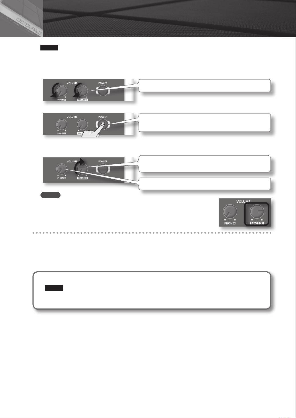
1. Lower the volume of the OCTAPAD and amplication system.
Turn the [PHONES] and [MASTER] knob all the way to the left.
2. Press the [POWER] button.
The OCTAPAD is equipped with a protection circuit. A brief interval (a few
seconds) after power up is required before the unit will operate normally.
3. Turn on the power of your speakers.
4. Adjust the volume.
While playing the pads of the OCTAPAD, slowly turn the [MASTER] knob
toward the right, and set the volume on the OCTAPAD and speakers.
Use the [PHONES] knob to adjust the volume of the headphones.
MEMO
Adjust your speaker system so that the volume is appropriate when the [MASTER] knob
is approximately at the 3 o’clock position as shown in the illustration. Turn the knob
toward the right to increase the volume, or toward the left to decrease it.
Turning the Power O
1. Minimize the volume of the OCTAPAD and your speakers.
2. Turn o the power of your speakers.
3. Hold down the [POWER] button until the display indicates “See you!”
Be sure to use the [POWER] button to turn o the power!
NOTE
The OCTAPAD automatically saves data during the power-down process. If power is turned o by unplugging
the AC adaptor or power cable, data will NOT be saved, and malfunctions may occur.
6
Page 7

Overview
Welcome to the world of the OCTAPAD.
This chapter provides an overall explanation of the OCTAPAD. Whether you are a beginner
or an experienced user of electronic musical equipment, reading this chapter will help you
save time and learn to operate the OCTAPAD smoothly.
Page 8

01 Overview of the OCTAPAD
What is an Inst?
All the sounds and instruments on board the OCTAPAD are referred to as
“INST.”
What is does Layer mean?
Two Insts (Inst A, Inst B) can be assigned to each pad.
“Inst Layer Type” (p. 30) lets you choose how the Layer function will
operate. The layered sounds can be mixed equally, or can be controlled
by playing dynamics. With a hi-hat for example, by playing softly you can
have the closed hi-hat sound, and when playing harder, the open hi-hat
sound (p. 33). Or you can use a snare drum sound, so when play softly you
hear the head sound, and when playing louder you can have a rim shot.
Volume
Playing
Dynamics
What is a Kit?
All instruments assigned to the eight pads and four external pads (p. 60)
as well as the eects used, are memorized as a “Kit.” You can select kits by
pressing the [KIT] buttons (or foot-switches).
In live performance situations, the Kit Chain function allows you to
determine the switching order of selected kits. See p. 37. Also there is a
Favorite function, giving you quick access to your favorite kits. See p. 22.
Volume
Playing
Dynamics
When the layer type is “FADE”When the layer type is “SWITCH”
8
Page 9
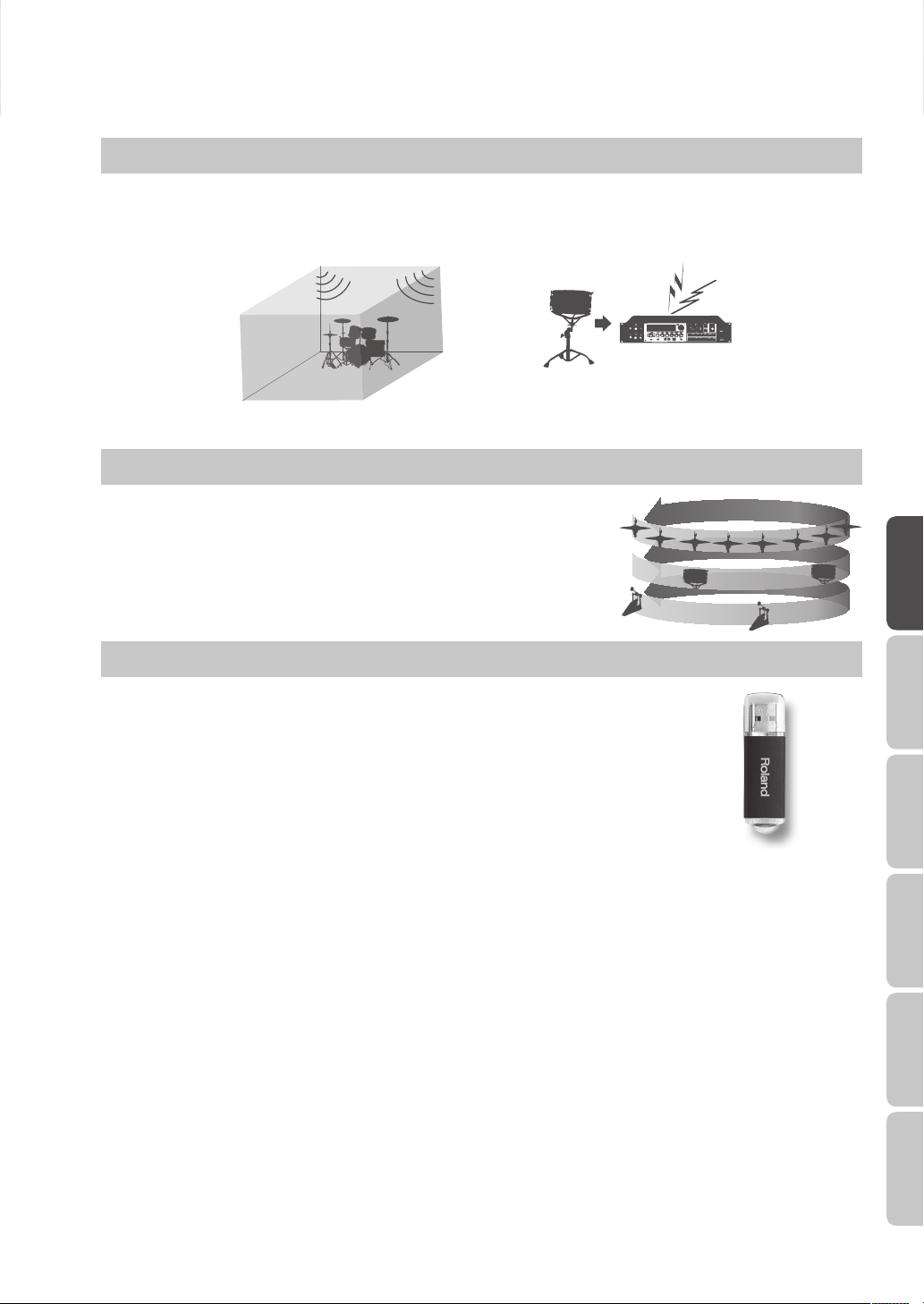
What are Ambience and FX?
The “Ambience” selected is a global function, meaning that all kits will use this eect. You can select from various types of
rooms and halls.
“FX” is a full blown eects unit that can be used on an individual kit basis.
Multi Eects Processor
Ambience FX
What is a Phrase Loop?
The Phrase Loop function is a recording feature that allows you to loop
record something in real time, and then overdub on top. The potential is
very exciting for live performances.
As each phrase has three “parts” it means, for example, that you can record
a 16-beat phrase on part 1, some Latin percussion on part 2, and a either
record or just perform a melodic percussion kit on top. It’s almost like
having three OCTAPADs!
Editing and Saving Your Data
Overview Basic Operation Adv. 1 (Kit) Adv. 2 (Phrase) Adv. 3 (Other) Appendix
The OCTAPAD features some powerful editing tools such as tuning, muing, tone color
etc. Also, the FX for each kit can be edited as well. This allows you to really personalize your
sound.
All of your edits are automatically saved internally. If you need to, you can restore an
individual kit to the factory settings. See “04 FACTORY RESET” (p. 20).
You can also use a USB memory (sold separately) to save your data. See p. 56.
9
Page 10

02 Panel Descriptions
Top Panel
Display, Buttons & Knobs
Function button 1–3
These buttons (from left to right) [Button 1], [Button 2], and [Button 3]
execute various functions indicated in the bottom of the display.
Function knob 1–3
These knobs (from left to right) [Knob 1], [Knob 2], and [Knob 3]
correspond to functions indicated by a knob icon ( ) in the display.
p. 16
p. 15
Button 1 Button 2 Button 3
Knob 1 Knob 2 Knob 3
[MENU] button
To access the main menu screen.
[QUICK] button
In screens that show a icon in the upper right, pressing this button will
call up various choices relative to the screen you are in.
[BACK] button
This button returns to the previous screen or cancels an operation.
p. 22
[KIT] buttons
Use these back-lit buttons to switch kits. When editing, pressing these
buttons will return you to the KIT screen.
* Be aware that the screen shots shown in this manual will not necessarily match the factory-set content
shown in your screen (Kit names, Inst names, and Eect names).
* You may notice some inconsistency in the contrast of the display; this is not a malfunction.
Adjust “LCD Contrast” (p. 52) appropriately to minimize the inconsistency in the display’s contrast.
10
Page 11
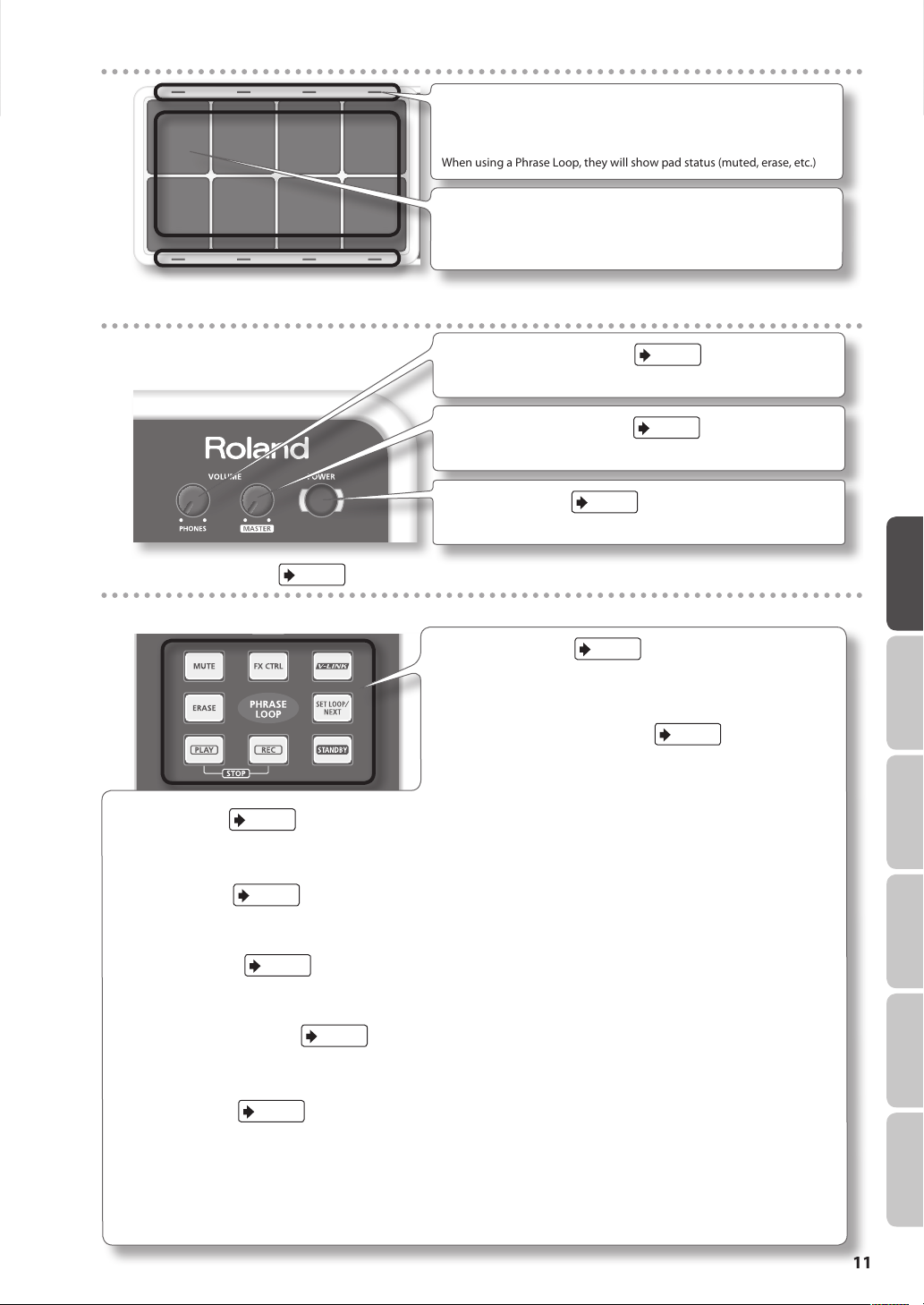
Playing area
Volume & Power
Pad Status Illumination
The LED indicators can be helpful when playing on a dark stage. See
“Illumination” (p. 52).
When using a Phrase Loop, they will show pad status (muted, erase, etc.)
Pad
Play them with sticks.
* Playing anything other than the pads can cause malfunctions.
p. 6
[VOLUME/PHONES] knob
Adjusts the headphone volume.
[VOLUME/MASTER] knob
Adjusts the volume of the OUTPUT jacks.
p. 6
[POWER] button
For turning the power on/o.
p. 6
Overview Basic Operation Adv. 1 (Kit) Adv. 2 (Phrase) Adv. 3 (Other) Appendix
p. 46
p. 47
p. 66
p. 41
p. 43
p. 47
p. 43
[STANDBY] button
For entering Phrase Loop mode. The Setup screen appears while holding
down this button, and you can use the pads to select the number of
measures.
[PLAY]/[REC] ([STOP]) button
These buttons switch between recording (overdubbing) and playing the
Phrase Loop. You can stop the phrase by pressing the [PLAY]/[REC] buttons
simultaneously.
p. 45
Phrase Loop area
[MUTE] button
While holding down this button and hitting a pad, you can mute or un-mute the corresponding track.
Mute status is shown in the display and by the pad’s illumination.
[ERASE] button
While holding down this button and hitting a pad, you can erase a specic portion of a track. Hit the pad at the moment you want to start
erasing, and once again when you want to stop. Erase status is shown in the display and by the pad’s illumination.
[FX CTRL] button
Press this button to access a screen allowing you to use the knobs to control eects. While in Phrase Loop record mode, these knob
movements will be recorded.
[SET LOOP/NEXT] button
When this button is blinking, you can set the loop point (p. 43).
When this button is lit, it is for reserving the operation (MUTE/PLAY/REC/STOP) that will occur at the beginning of the next loop (p. 47).
[V-LINK] button
Pushing this button selects V-LINK mode, allowing you to control video devices in real time.
This button will function even when not in Phrase Loop Mode.
“PHRASE LOOP” tempo Indicator
This blinks in time with tempo. To turn this function o, see “Tempo Indicator” (p. 52).
11
Page 12
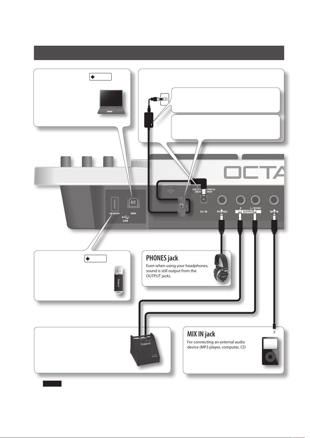
Rear Panel Connections
USB MIDI connector
With a USB cable, you can
connect the OCTAPAD to
your computer for triggering
sounds or recording MIDI
information to your software
sequencer (DAW).
p. 58
DC IN jack
Connect the included AC adaptor here.
Place the AC adaptor so the side with the indicator (see illustration)
faces upwards and the side with textual information faces
downwards. The indicator will light when you plug the AC adaptor
into an AC outlet.
To prevent the inadvertent disruption of power to your unit
(should the plug be pulled out accidentally), and to avoid applying
undue stress to the AC adaptor jack, anchor the power cord using
the cord hook, as shown in the illustration.
12
p. 55
USB MEMORY slot
With a USB memory (sold separately)
you can backup and load your data.
OUTPUT jacks
For connection to your amplication or
recording system.
If making a MONO connection, use the L/MONO
jack.
PHONES jack
Even when using your headphones,
sound is still output from the
OUTPUT jacks.
MIX IN jack
For connecting an external audio
device (MP3 player, computer, CD
player etc). This audio signal will be
sent to the OUTPUT and PHONES
jacks.
NOTE
• To prevent malfunction and/or damage to speakers or other devices, always turn down the volume, and turn o the
power on all devices before making any connections.
• When connection cables with resistors are used, the volume level of equipment connected to the inputs (MIX IN)
may be low. If this happens, use connection cables that do not contain resistors.
Page 13
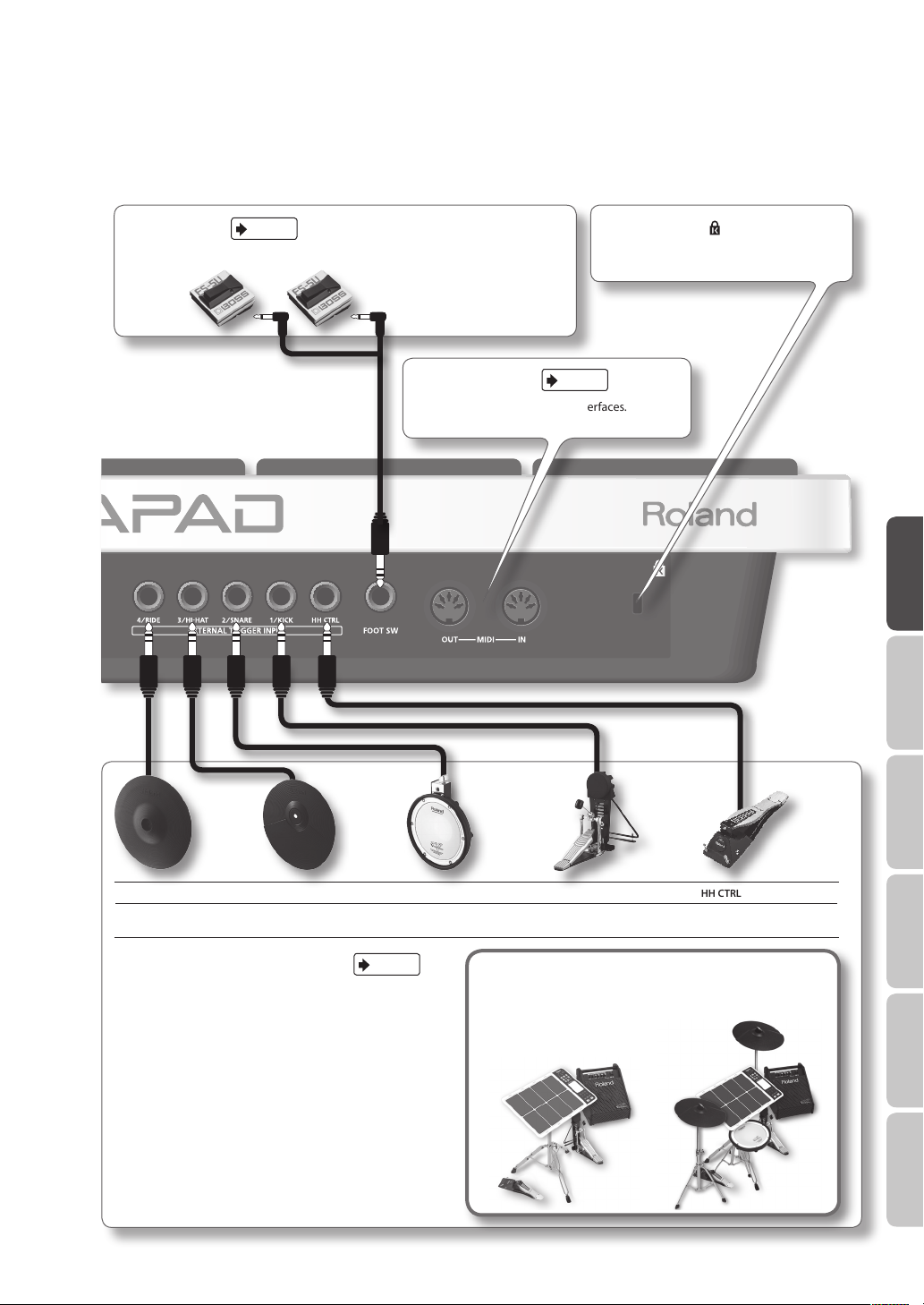
p. 53
FOOT SW jack
You can connect a pair of foot switches to this input for various possibilities.
MIDI connectors
For connecting MIDI modules/interfaces.
Security slot ( )
http://www.kensington.com/
p. 63
Overview Basic Operation Adv. 1 (Kit) Adv. 2 (Phrase) Adv. 3 (Other) Appendix
4/RIDE 3/HI-HAT 2/SNARE 1/KICK HH CTRL
V-cymbal
(e.g., CY-12R/C)
EXTERNAL TRIGGER INPUT jacks
Even though jacks 1–4 have specic indications, you can use
them as you like. Make sure you use the respective cables
(stereo) for dual trigger pads/cymbals. All these options are for
products sold separately.
The HH CTRL jack is for using with compatible controllers such
as an FD-8 or VH-11.
For details on how to attach the pad stand, refer to “Attaching the Stand (Sold Separately)” (p. 69).
Cymbal pad
(e.g., CY-5)
p. 60
V-pad
(e.g., entire PD series)
Kick trigger pad
(e.g., KD-8, KD-7)
Hi-hat control pedal
(FD-8, VH-11)
Connect optional pedals and pads
You can expand the possibilities of the OCTAPAD by connecting optional
pedals and pads. This way you can play with your hands and feet.
Here are some examples.
13
Page 14
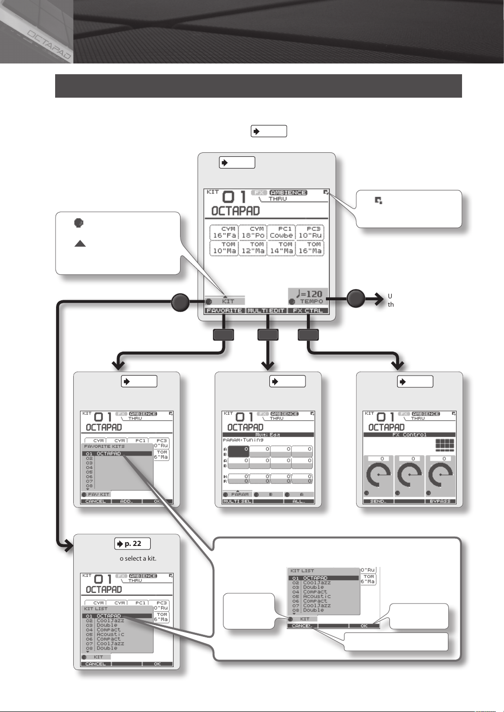
03 Displays and Operations
KIT Screen
The KIT screen is the basic screen that appears after powering up the OCTAPAD. The function buttons and knobs below
the screen are used to navigate between screens. Press the [BACK] button to return to the KIT screen.
For details on each screen, refer to the indicated pages
KIT
This is the basic screen for playing a kit.
The icons indicate which function
knob can be used.
icon means a popup list will
The
appear when you turn the knob.
p. 22
p.
.
The icon is shown in the
upper right of the screen when a
quick menu is available.
Use [Knob 3] to adjust
the tempo.
p. 22
FAVORITE
Register/recall favorite kits.
KIT LIST
Use [Knob 1] to select a kit.
p. 22
p. 24
MULTI EDIT
Edit various parameters.
Basic operations in the list screen
Turn the knob
below the list
to choose
p. 41
FX CTRL
Use [Knobs 1–3] to control
eects.
Press [Button 1] (CANCEL) to cancel
Press [Button 3]
(OK) to conrm
14
Page 15
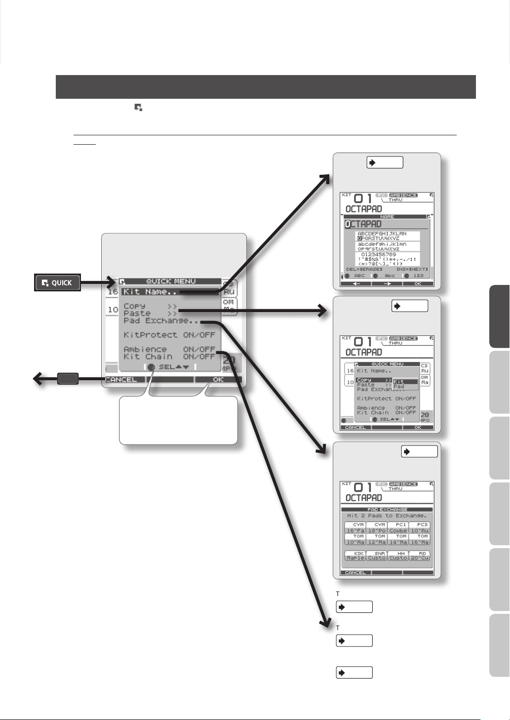
QUICK MENU Screens
When you see the icon in the upper right of the screen, pressing the [QUICK] button accesses the relative menu. We’ll
use the Quick Menu that appears in the KIT screen as an example.
In this manual, we’ll use “QUICK MENU Ú Kit Name” to refer to the operation of choosing Kit Name from the QUICK
MENU.
p. 35
NAME
Assign a name to the kit.
QUICK MENU
This is a menu suitable for each screen.
Pressing [Button 1]
(CANCEL) takes you to
the previous screen.
Use [Knob 2] (SEL) to select an item,
and use [Button 3] (OK) to conrm
your choice (i.e., move to that
screen).
p. 35
COPY/PASTE
Copy/paste kit or pad data.
PAD EXCHANGE
Exchange pads.
p. 36
Overview Basic Operation Adv. 1 (Kit) Adv. 2 (Phrase) Adv. 3 (Other) Appendix
* When “Kit Protect” (p. 34) is on, certain parameters are not
available. They are highlighted in a grey color.
Turn kit protect on/o.
p. 34
Turn ambience on/o.
p. 42
Turn kit chain on/o.
p. 37
15
Page 16
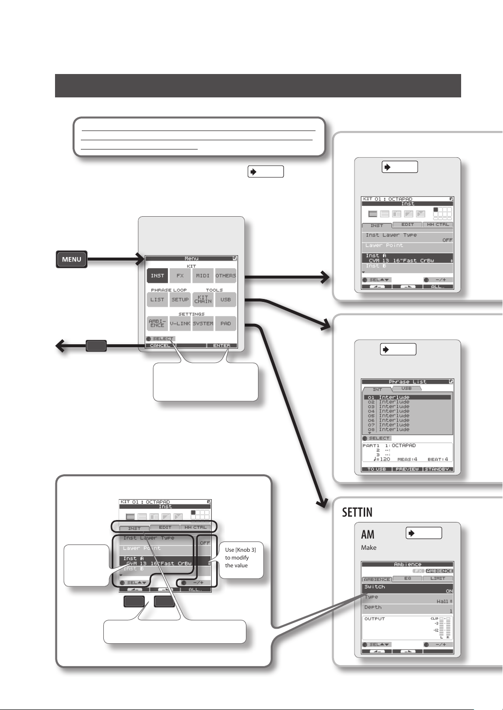
MENU Screen
Accessible from any screen pressing the [MENU] button takes you to the OCTAPAD’s main menu.
In various explanations regarding the screens and menus, when you see,
for example,“choose MENU Ú SYSTEM Ú F.RESET,” the “Ú” points to
the next selection you should make.
For details on each screen, refer to the pages listed on
MENU
This is the main menu screen.
Pressing [Button 1]
(CANCEL) takes you to
the previous screen.
Use [Knob 1] (SELECT) to
choose, and press [Button 3]
(ENTER) to conrm.
p.
.
KIT
PHRASE LOOP
p. 30
INST
Edit an Inst.
p. 50
LIST
Select a phrase.
16
Basic operations in each screen
Use [Knob 1]
to select a
parameter
Use [Button 1] or [Button 2] to move to the tab, left
or right
* Press the [BACK] button to return to the previous screen.
Use [Knob 3]
to modify
the value
SETTINGS
AMBIENCE
Make ambience-related settings.
p. 42
Page 17

MENU screen Quick Menu
If you press the MENU button and then press the [QUICK] button you will see “Force Save Data” in the pop-up window.
By pressing [Button 3] (OK) current data will be saved. (Also, The OCTAPAD will save your data automatically during the power-o
process).
p. 39
FX
Make eect (FX) settings.
p. 51
SETUP
Make phrase loop settings.
p. 63
MIDI
Make MIDI settings for the kit.
TOOLS
KIT CHAIN
Switch kits in an order you
specify.
p. 37
p. 34
p. 55
OTHERS
Make other settings such as the
kit’s volume or tempo.
USB
Save/load data on USB memory.
Overview Basic Operation Adv. 1 (Kit) Adv. 2 (Phrase) Adv. 3 (Other) Appendix
p. 66
V-LINK
Make V-LINK settings.
p. 52
SYSTEM
Make system settings that apply
to the entire OCTAPAD.
p. 59
PAD
Make pad-related settings such
as pad sensitivity.
17
Page 18
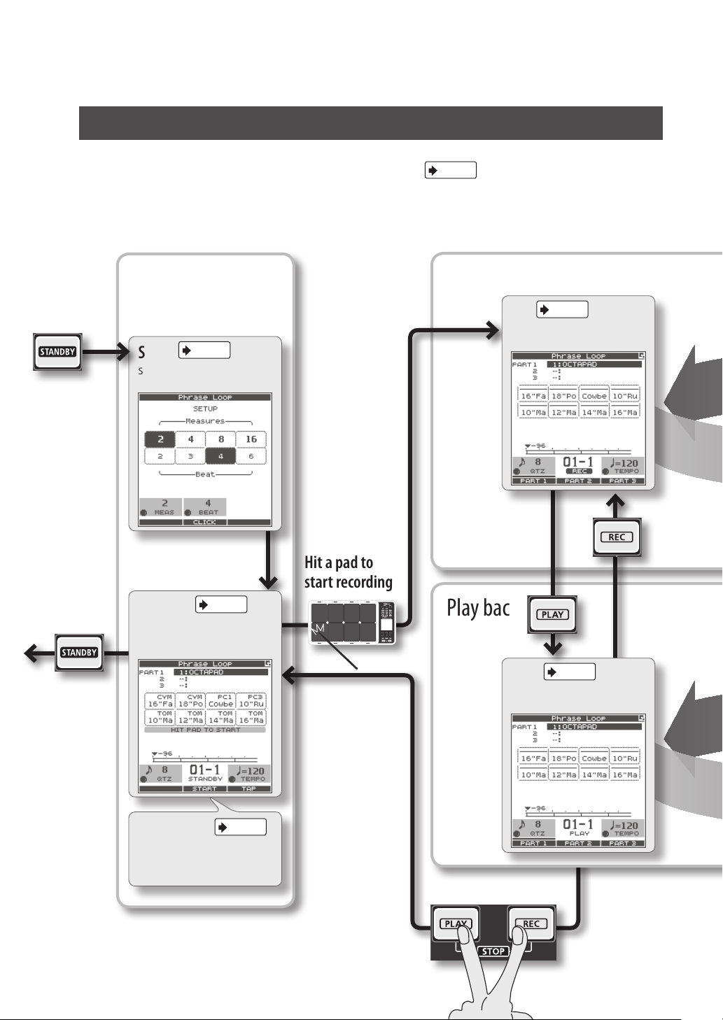
PHRASE LOOP Screen
Pressing the [STANDBY] button takes you to a page where you can set parameters of the phrase you are about to create.
For details on each screen, refer to the page references shown below
If you want to simply learn the operations, refer to “05 Recording a Phrase Loop (PHRASE LOOP)” (p. 26) in the Basic
Operation section.
.
p.
Press the
[STANDBY] button
to enter Phrase
Loop mode.
From the standby
state (stopped),
pressing the
[STANDBY] button
will make it go dark.
You will exit Phrase
Loop mode and
return to the KIT
screen.
Make settings
Shown while you hold down the
[STANDBY] button
p. 43
SETUP
Specify the measures, beat, and
click.
Enter standby mode
STANDBY
Make quantize and tempo settings, and enter record-standby
mode.
p. 44
Hit a pad to
start recording
Record
Play back
p. 45
REC
Record your phrase.
p. 45
PLAY
Switch to PLAY mode.
18
p. 44
QUICK MENU
Load, save, or delete phrases.
Stop
Page 19
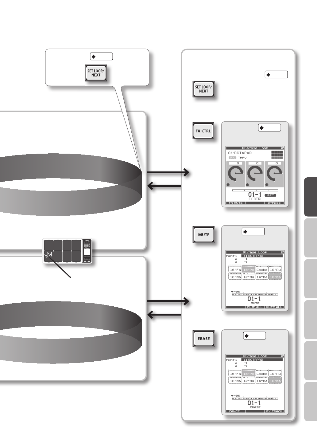
p. 43
Set loop points
Loop recording
Record an additional performance
Modify the phrase
Reserve the next operation
Control the eect
FX CONTROL
Use [Knob 1–3] to control the
eect.
Mute
p. 46
MUTE
Mute the selected track.
p. 41
p. 47
Overview Basic Operation Adv. 1 (Kit) Adv. 2 (Phrase) Adv. 3 (Other) Appendix
Perform along with the
phrase playback
Loop playback
Erase
p. 47
ERASE
Erase the selected track.
19
Page 20
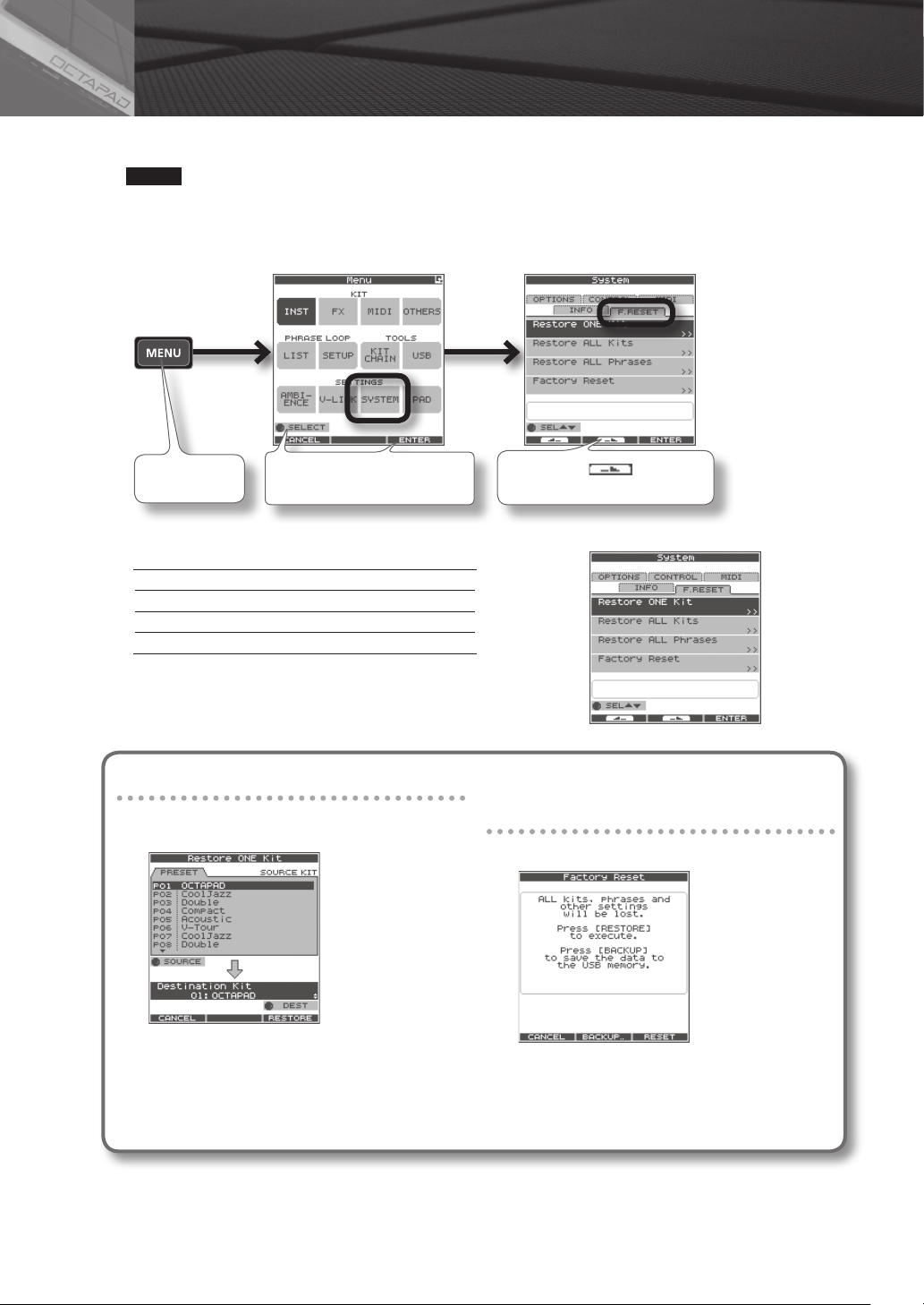
04 FACTORY RESET
The restore function gives you a choice of restoring individual kits or all of them, all phrases, or a full Factory Reset.
NOTE
When you perform the Factory Reset operation, the kits and phrase data saved in the OCTAPAD will be initialized. If
there’s any data you want to keep, be sure to back it up to USB memory as described in “Saving Data to USB Memory
(USB-SAVE)” (p. 56).
1. Choose MENU Ú SYSTEM Ú F.RESET.
Press the [MENU]
button
2. Turn [Knob 1] (SEL) to the reset function and press [Button 3] (ENTER).
Restore ONE Kit Restore a specic kit
Restore ALL Kits Restore all kits
Restore ALL Phrases Restore all phrases
Factory Reset Resets all data
* When “Write Protect” (p. 52) is ON, restore and factory reset functions
are not available. They are highlighted in grey.
3. Proceed as follows.
Turn [Knob 1] to select ”SYSTEM,” and
press [Button 3] (ENTER)
If you selected “Restore One Kit”
This function actually copies pre-set kit data stored
in the OCTAPAD’s internal memory.
Press [Button 2] ( ) to select the
“F.RESET” tab
If you selected Restore All Kits/
Phrases/Factory Reset
The following screen message will appear.
3-1. Use [Knob 1] (SOURCE) to select the source kit.
3-2. Use [Knob 3] (DEST) to select the destination kit.
3-3. Press [Button 3] (RESTORE) to execute.
• [Button 1] (CANCEL) will cancel the operation.
4. When the conrmation message appears, press [Button 3] (OK).
The reset will be executed. Never turn o the power during the reset process.
20
3-1. Press [Button 3] (RESTORE or RESET) to execute.
• Press [Button 2] (BACKUP) to go to the USB-SAVE screen
(p. 56).
• [Button 1] (CANCEL) will cancel the operation.
Page 21

Basic Operation
It is important to understand the basic operations and functions of the OCTAPAD before
using it. Please read this section fully as you check out the OCTAPAD’S possibilities.
Page 22
01 Selecting a Kit
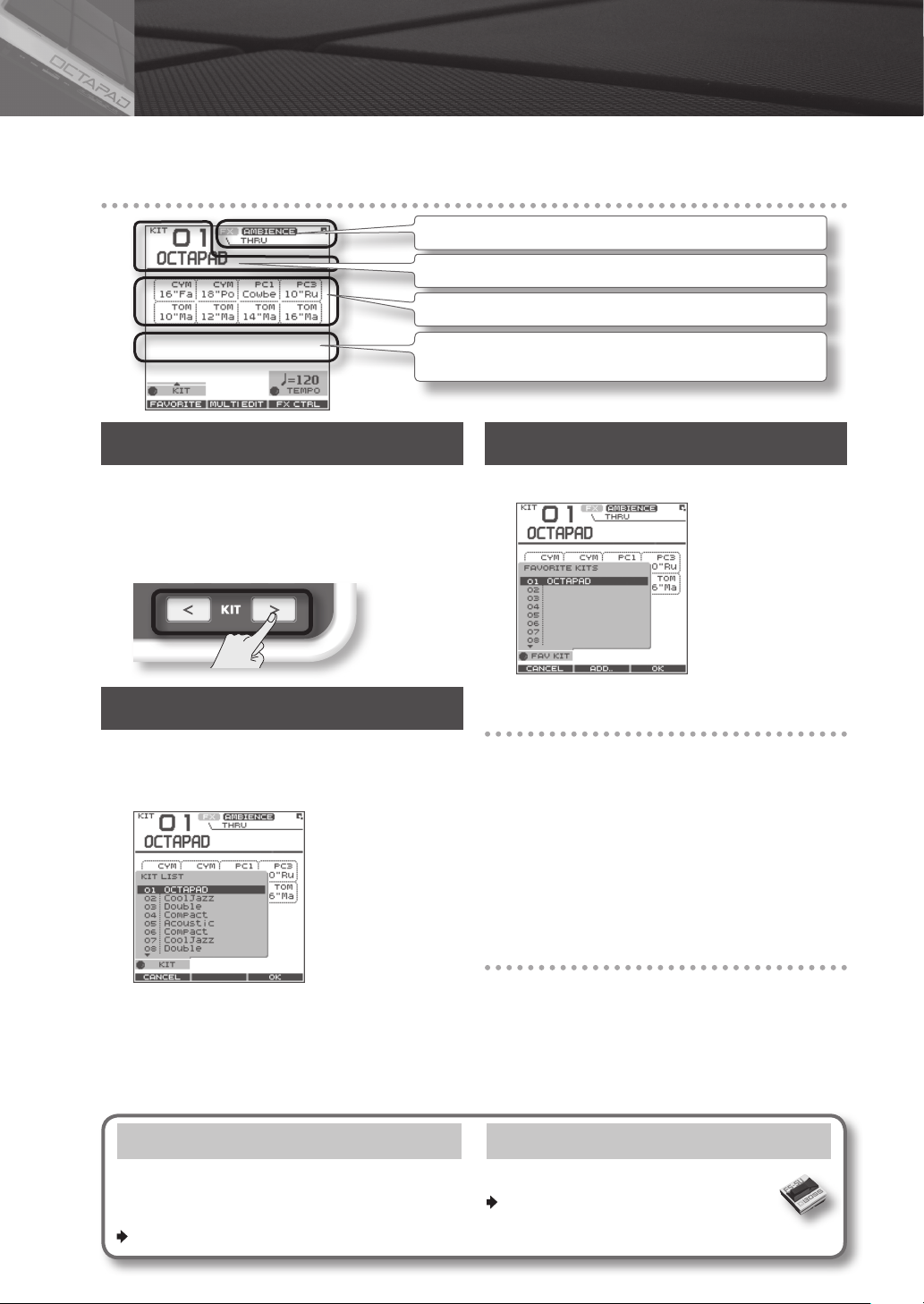
Select any kit. The kit number and name appear in the KIT screen.
Information shown in the KIT screen
Indicates if the FX/ambience are on or o and the FX name.
Kit number/Kit name.
The Inst and group names are highlighted when you play the pads.
The external trigger indicators can be turned on or o.
See “Ext Pad Indicator” (p. 52).
[KIT] Buttons
1. Use the backlit [KIT] buttons to switch kits.
The kit will change immediately, or if you are in any edit
screen you will return to the current KIT.
By holding down either of the buttons, scrolling speed
increases.
KIT LIST
1. In the KIT screen, turn [Knob 1] (KIT).
The KIT LIST appears. Turn the same [Knob 1] to move
the cursor.
FAVORITE KITS
Here’s how to register and recall your favorite kits.
How to Register a favorite kit
1. In the KIT screen, press [Button 1] (FAVORITE)
and the list appears.
2. Turn [Knob 1] (FAV KIT) to select the destination
(10 possibilities).
3. Press [Button 2] (ADD).
The “current” Kit you had selected before pressing the
FAVORITE button will be assigned to your destination
choice.
How to Recall a favorite kit
2. Press [Button 3] (OK) to select.
The kit will switch.
KIT CHAIN Function
The Kit Chain function allows you specify the order
in which kits will switch. Very convenient for live
performance.
For details, refer to “KIT CHAIN” (p. 37).
22
1. In the KIT screen, press [Button 1] (FAVORITE)
and the list appears.
2. Use [Knob 1] (FAV KIT) to choose.
3. Press [Button 3] (OK).
You’ll switch to the kit that is selected in the list.
Foot Switch
Foot switches can be used to change kits.
For details, refer to “Foot Switch and
External Pad Settings (SYSTEM-CONTROL)”
(p. 53).
Page 23
02 Selecting an Inst (INST)
Here’s how to change or assign an Inst to each pad. More about Insts and Layers is here: “What is an Inst?” (p. 8).
The changes you make here are saved. You can’t modify a kit whose “Kit Protect” (p. 34) is on.
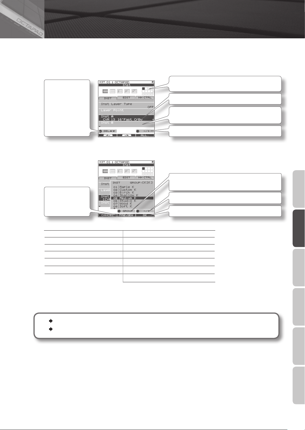
1. Choose MENU Ú INST Ú INST (p. 16).
The INST screen appears.
Use [Knob 1] (SEL) to
select a parameter.
The cursor will
Initially be at Inst A,
so turning
[Knob 3] (–/+) will
change Inst A.
2. Play any pad whose Inst you want to change.
3. Turn [Knob 3] (–/+) to select an Inst.
Indicates the pad you’re currently editing and will change
when you play any pad.
Select Inst A.
Select Inst B.
(This will not work if Inst Layer Type is “OFF”)
Turn [Knob 3] (–/+) to modify the value.
Press
[Button 2] (PREVIEW)
to audition the Inst.
List of Inst groups
KIK Kick (bass drum) PC1 Percussion with heads
SNR Snare drum PC2 Metallic percussion
TOM Tom-tom PC3 Miscellaneous percussion
HH Hi-hat cymbal PC4 Melodic percussion
RD Ride cymbal MEL Pitched instruments
CYM Crash cymbal SFX Sound eects
OFF O
4. Repeat steps 2–3 to select the Inst for other pads.
5. Press the [BACK] button to return to the KIT screen.
Information on layer and other parameters, can be found here: “Inst Settings (INST)” (p. 30)
You can exchange data between the pads. Refer to “Exchanging Pads (PAD EXCHANGE)” (p. 36).
Turn [Knob 2] (GROUP) to select the Inst group.
Turn [Knob 3] (–/+) to select an Inst.
Press [Button 3] (OK) to conrm the selected Inst.
Overview Basic Operation Adv. 1 (Kit) Adv. 2 (Phrase) Adv. 3 (Other) Appendix
23
Page 24
03 MULTI EDIT
What is Multi Edit?
Pushing the Multi Edit button gives you access to 10 dierent editing parameters. (See the chart below)
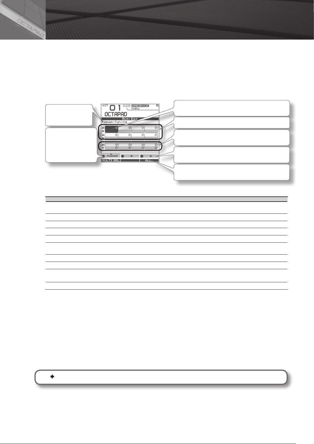
1. In the KIT screen, press [Button 2] (MULTI EDIT).
The Multi Edit screen appears.
Here you can see all the relative values assigned to each pad and external trigger input.
The changes you make are saved in the kit. You can’t edit a kit whose “Kit Protect” (p. 34) is on.
Name of the
parameter you’re
editing
Turn [Knob 1] (PARAM)
and a popup list
appears select a
parameter here.
Indicates the pad you’re editing and will change when you
play a pad.
Value of each pad (Inst A is above, Inst B is below)
Values for external trigger inputs 1–4 (Head is above, Rim
is below)
Use [Knob 2] (B) to change the value of Inst B (Rim).
Use [Knob 3] (A) to change the value of Inst A (Head).
Press [Button 3] (ALL) to copy the current value to all pads
and external triggers.
2. Turn [Knob 1] (PARAM) to select the parameter and press [Button 3] (OK) to conrm your choice.
Parameter Value Explanation
Tuning -2400–+2400
Coarse Tune -2400–+2400 This is the same as Tuning, but the value will change in steps of 100 as you turn the knob.
Muing 0–50 Increasing the value will decrease the resonance and decay.
Soft Attack 0–50 Species the sharpness of the attack. Increasing the value will soften the sound’s attack.
Tone Color L50–H50 Modies the brightness of the sound. Higher settings will produce a brighter sound.
Pitch Sweep -100–+100
Volume 0–100 Species the volume.
Pan L15–CTR–R15 Species the pan position. CTR is center.
Reverse OFF, ON
FX Send 0–100 or OFF, ON Determines the send level to FX (eect). Adjust accordingly.
Negative (“-”) values will lower the pitch; positive (“+”) values will raise the pitch. The value will change
in steps of 10 as you turn the knob.
Positive (“+”) settings will make the pitch change from high to low. Negative (“-”) settings will make the
pitch change from low to high.
If this is ON, the pad’s sound will play backward.
* Some Insts will NOT play in reverse.
3. Hit a pad to select it for editing.
• If you want to edit multiple pads at the same time, hold down [Button 1] (MULTISEL) and play the desired pads.
• If you hit a pad that is not selected, it will cancel the multi selection.
To stay in this multi selection mode, only play the pads you have selected.
4. Use [Knob 3] (A) or [Knob 2] (B) to edit the value.
• [Knob 3] (A) changes the value for Inst A (Head).
• [Knob 2] (B) changes the value for Inst B (Rim).
5. Press the [BACK] button to return to the KIT screen.
If you want to adjust the pad’s sensitivity, refer to “Internal Pad Sensitivity Settings” (p. 59).
24
Page 25

04 Eects Editing (AMBIENCE and FX)
For an overview of the eects, refer to “What are Ambience and FX?” (p. 9).
AMBIENCE
1. Choose MENU Ú AMBIENCE Ú AMBIENCE (p. 16).
The AMBIENCE screen appears. Use [Knob 1] and [Knob 3] to switch ambience on/o or change its type.
Turns ambience on/o
Ambience type
Use [Knob 1] (SEL) to
select a parameter.
MEMO
In the KIT screen, you can also turn ambience on/o by using QUICK MENU Ú Ambience ON/OFF.
Ambience depth
Turn [Knob 3] (–/+) to edit the value.
FX
1. Choose MENU Ú FX Ú TYPE (p. 16)
The FX screen appears. Use [Knob 3] to switch the FX type.
Pad for which FX will apply
FX type
A diagram of the
selected FX type will
appear.
Using the knobs to control FX
1. Press the [FX CTRL] button.
The FX CONTROL screen appears. You can use [Knob 1]–[Knob 3] to control the FX parameters. The most suitable
parameters for the eect will automatically be assigned to the knobs. Changes you make in the FX CONTROL screen are
not saved to the kit.
Use [Knob 3] (TYPE) to display the FX type list.
[Button 3] (BYPASS) temporarily turns FX o.
Overview Basic Operation Adv. 1 (Kit) Adv. 2 (Phrase) Adv. 3 (Other) Appendix
FX type
Pad for which FX is enabled
Use [Button 1] (SEND)
to move to a screen
in which you can
adjust each pad’s
send level.
For details on how to edit each parameter, refer to “AMBIENCE” (p. 42) and “FX” (p. 39).
Use [Knob 1–3] to edit the eect parameters.
[Button 3] (BYPASS) temporarily turns FX o.
25
Page 26

05 Recording a Phrase Loop (PHRASE LOOP)
To simply explain the Phrase Loop function we will use the basic 8-beat phrase shown below.
Step 1: Select a Kit
1. Use the [KIT] buttons to select the acoustic kit “50: Tutorial.”
In kit “50: Tutorial,” instruments are assigned to pads as follows. Start by practicing this phrase.
Hi-hat cymbal
Step 2: Make Settings Before Recording
Measures, Time Signature (Beat) and Metronome (Click) Sound settings
Hold down the [STANDBY] button and the PHRASE LOOP SETUP screen appears.
Snare drum
Kick (bass drum)
The screen you will see here will indicate, in the top row, the
length of the phrase (Measures). The time signature (Beat) is
Press [Button 2]
(CLICK); a bar
appears above the
button, and the click
(Metronome) will
start.
1. Hold down the [STANDBY] button and make your choice by hitting the relative pad or by turning
[Knob 1] (MEAS) or [Knob 2] (BEAT).
As shown in the illustration, please select (2 measures, 4 beats) for this recording.
2. Press [Button 2] (CLICK).
You’ll hear the click (Metronome).
MEMO
• The click sound can also be turned on/o from the PHRASE LOOP screen by choosing the Quick Menu “Click ON/OFF”
command.
• The blinking tempo indicator (
performance), you can turn o the click sound and record while watching the blinking tempo indicator.
• As described in “Metronome (Click) Sound Settings (PHRASE LOOP SETUP-CLICK)” (p. 51), you can make settings such as
“sounding the click only on the rst pass of the loop,” changing the type of click sound, or adjusting the click volume.
) also shows the rhythm. If you don’t want to hear a click (such as in a live
indicated in the lower row.
26
Page 27

Quantization and tempo settings
What is quantization?
Quantization is a function that automatically corrects the timing of your playing. It only functions during the
recording process. By making the appropriate quantization setting, you choose between resolution intervals of 8th
notes, 12th note triplets, 16th notes, or 24th note triplets.
When you take your nger o the [STANDBY] button, it will light and the PHRASE LOOP screen appears.
Turn [Knob 1] (QTZ)
to select the quantize
interval.
Or select “OFF.”
To start recording, press
[Button 2] (START) or hit
a pad.
Now make settings for the phrase that you will record (quantize to 8th notes, tempo 100).
The currently selected kit is shown.
Turn [Knob 3] (TEMPO) to set the tempo.
You can set the tempo manually by tapping [Button 3] (TAP)
four times or more. You can also set the tempo by holding
down [Button 3] (TAP) and playing a pad four times or more.
3. Turn [Knob 1] (QTZ) to set quantization to “ 8” (8th notes).
If you’re condent that you have precise timing, you can leave this setting “OFF.”
4. Turn [Knob 3] (TEMPO) to set the tempo at “100.”
MEMO
You can also set the tempo of the phrase before entering standby mode, in the kit screen.
Step 3: Recording
Play the pads in rhythm with the click. Recording automatically begins the moment you hit the rst pad.
* Recording or playback will not start even if you press the [REC] button or [PLAY] button. These buttons only switch
between Record and Play modes. In order to start the phrase, you must either hit a pad or press [Button 2] (START).
1. Hit the pads to record the phrase.
Although you are free to record all pads at the same time, you can also record (overdub) each pad individually, for example
by starting with the bass drum, then recording the snare drum, and then the hi-hat etc.
Overview Basic Operation Adv. 1 (Kit) Adv. 2 (Phrase) Adv. 3 (Other) Appendix
Record the hi-hat on
the third pass
Record the snare
drum on the second
pass
Record the bass
drum on the rst
pass
Start recording!
2. When you’re nished recording, press the [PLAY] button.
The [PLAY] button lights, and you’re switched to Play mode. The phrase will play only. No recording is possible.
• If you press the [REC] button again, you return to the Record (REC) mode.
• To stop the phrase, hold down the [PLAY] button and press the [REC] button.
27
Page 28

Re-doing the Recording
If you want to re-do the recording, it’s easy to use the following methods.
Erasing a Track (ERASE)
During playback or recording, you can erase just the track of a specic pad.
Start erasing Stop erasing
1. Hold down the [ERASE] button, and when you want to start erasing, hit the pad whose track you want
to erase.
That pad’s illumination will blink while its track is being erased.
2. Hold down the [ERASE] button, and when you want to stop erasing, hit the pad whose track was being
erased.
Undoing a Recording (UNDO)
You can undo the previous recording or erasure. Perform the following step immediately after you’ve recorded or erased
data. You can’t undo once you’ve stopped the phrase.
1. In the PHRASE LOOP screen (during PLAY or REC), choose the QUICK MENU command Undo REC (or
Undo ERASE).
Clearing the Phrase (CLEAR PHRASE)
If you want to re-record from scratch, you can clear the phrase.
1. In the PHRASE LOOP screen (while stopped), choose the QUICK MENU command Clear Phrase.
2. When the conrmation message appears, press [Button 3] (OK).
Saving the Phrase (SAVE PHRASE)
The recorded phrase will be lost when you exit Phrase Loop mode, select a dierent phrase, or turn o the power. If you
want to keep the phrase, you can save it to internal memory or to USB memory.
1. In the PHRASE LOOP screen (while stopped), choose the QUICK MENU command Save Phrase.
When the SAVE PHRASE screen appears, save the phrase as described in the procedure on p. 49.
Exiting Phrase Loop Mode
In the standby condition (while stopped), press the [STANDBY] button to make it go dark; you’ll exit Phrase Loop mode
and return to the KIT screen.
* If you leave the phrase loop mode without saving your data it will be lost. (A reminder will appear in the screen.)
Advanced techniques
In addition to the Phrase Loop functions explained here, you can mute a specic pad, record knob movements
while you use the knobs to control an eect, or reserve the operation that will occur on the next loop.
For details, refer to “Editing a Phrase” (p. 46).
28
Page 29

Advance Operation
1 Kit . . . . . . . . . . . . . . . . . . . . . . . . . . . . . . . . . . . . . . . . . . . .p. 30
This chapter explains how to create a kit and use eects.
2 Phrase Loop . . . . . . . . . . . . . . . . . . . . . . . . . . . . . . . . . .p. 43
This chapter provides a full explanation of the Phrase Loop functionality.
3 Other Settings . . . . . . . . . . . . . . . . . . . . . . . . . . . . . . . .p. 52
This chapter explains settings such as pad and pedal calibration,
and how to connect MIDI and USB equipment.
Page 30

Advance Operation 1 (Kit)
Creating a Kit
Inst Settings (INST)
Inst and Layer Settings (INST-INST)
For more about Insts and Layers, refer to “What is an Inst?” (p. 8). How to access individual Inst parameters for each pad.
1. Choose MENU Ú INST Ú INST (p. 16).
The INST-INST screen appears.
Darkened pad indicator is the pad you’re editing. Hit the pad
to change this.
Turn [Knob 3] (–/+) to edit the value.
Use [Knob 1] (SEL) to
select a parameter.
2. Hit the pad that you want to edit; it will be selected.
3. Turn [Knob 1] (SEL) to select a parameter.
4. Turn [Knob 3] (–/+) to edit the value.
Parameter Value Explanation
OFF
MIX
Inst Layer Type
SWITCH
Volume
Volume
Volume
Volume
Playing
Dynamics
Playing
Dynamics
Playing
Dynamics
Press [Button 3] (ALL) to copy the current value to all pads
and external triggers.
Only Inst A will play.
If Layer is set to other than OFF, the indication shown in this
illustration will appear at the upper left of the Inst name
indication in screens such as the KIT screen.
Inst A and Inst B will both play together.
If the Layer Point has been specied, Inst
B will be heard only when you hit the pad
more strongly than the specied Layer Point
velocity value, as shown in the illustration
at right.
Hits that are softer than the Layer Point will play Inst A, and hits that are stronger
will play Inst B.
Volume
Playing
Dynamics
FADE
Playing
Dynamics
Volume
XFADE
Playing
Dynamics
Layer Point 1–127 Species the velocity value at which Inst B will start being heard.
Inst A Selects Inst A. For details on how to select this, refer to “02 Selecting an Inst (INST)” (p. 23).
Inst B Selects Inst B. For details on how to select this, refer to “02 Selecting an Inst (INST)” (p. 23).
On an acoustic drum set, for example, the open hi-hat and closed hi-hat will not be heard simultaneously. You can
Mute Group OFF, 1–6
Dynamics OFF, ON If you choose OFF, playing dynamics will be ignored, and the Inst will only sound at the maximum velocity (127).
use Mute Group settings to simulate this behavior.
Mute Group is a function that prevents Insts of the same mute group setting from being heard together. You can
specify six mute groups. If you don’t want an Inst to belong to any mute group, choose “OFF.”
Inst B will be added to Inst B when you play more strongly than the Layer Point.
This is essentially the same as FADE, but Inst A will decrease as you play the pad
more strongly than the Layer Point.
30
Page 31

You can’t select Inst Layer Type for an external pads
For external pads (p. 60), you can only use 2 sounds: Inst Head and Inst Rim. (Dual trigger pad is needed to have head and rim
sounds) Refer to the owner’s manual of the pad you’re using.
Internal pads External pads
Inst A Inst Head
Inst B Inst Rim
Head shot
Inst Head Inst Rim
Rim shot
Editing an Inst (INST-EDIT)
Here’s how to access the various editing parameters.
1. Choose MENU Ú INST Ú EDIT (p. 16).
The INST-EDIT screen appears.
Indicates the pad you’re editing; hit a pad to change this.
[Knob 2] (B) edits the Inst B (Rim) value.
[Knob 3] (A) edits the Inst A (Head) value.
Use [Knob 1] (SEL) to
select a parameter.
Press [Button 3] (ALL) to copy the current value to all pads.
2. Hit the pad that you want to edit; it will be selected.
3. Turn [Knob 1] (SEL) to select a parameter.
4. Turn [Knob 3] (A) or [Knob 2] (B) to edit the value.
• [Knob 2] (B) edits the Inst B (Rim) value.
• [Knob 3] (A) edits the Inst A (Head) value.
Parameter Value Explanation
Tuning -2400–+2400
Muing 0–50 Increasing this value will decrease the resonance and decay of the sound.
Soft Attack 0–50 Adjusts the sharpness of the sound’s attack. Higher settings will produce a softer attack.
Tone Color L50–H50 Adjusts the brightness of the sound. Higher settings will produce a brighter sound.
Pitch Sweep -100–+100
Volume 0–100 Species the volume.
Pan L15–CTR–R15 Species the pan setting. CTR is center.
Reverse OFF, ON
Negative (“-”) settings lower the pitch, and positive (“+”) settings raise the pitch. Turning the knob will change
the value in steps of 10.
Positive (“+”) settings make the pitch sweep from high to low. Negative (“-”) settings make the pitch sweep from
low to high.
If this is ON, the pad’s sound will play backward.
* Some Insts will NOT play in reverse.
Overview Basic Operation Adv. 1 (Kit) Adv. 2 (Phrase) Adv. 3 (Other) Appendix
31
Page 32

Hi-hat Settings (INST-HH CTRL)
Here you can decide how the hi-hat Inst will sound, and choose the Inst to be controlled by a hi-hat control pedal (FD-8: sold
separately).
1. Choose MENU Ú INST Ú HH CTRL (p. 16).
The INST-HH CTRL screen appears.
Values for each pad (Inst A is above, Inst B is below)
[Knob 1] (PAD SEL)
selects the pad to
edit.
Values for external trigger inputs 1–4 (Head is above, Rim
is below)
[Knob 2] (B) edits the Inst B (Rim) value.
[Knob 3] (A) edits the Inst A (Head) value.
2. Turn [Knob 1] (PADSEL) (or hit a pad) to select the pad that you want to edit.
3. Turn [Knob 3] (A) or [Knob 2] (B) to edit the value.
• [Knob 2] (B) edits the Inst B (Rim) value.
• [Knob 3] (A) edits the Ins A (Head) value.
Parameter Value Explanation
For the hi-hat Inst
CLOSE Plays the closed hi-hat sound.
HALF Plays the half-open hi-hat sound.
OPEN Plays the open hi-hat sound.
HH CTRL
PEDAL
For other than the hi-hat Inst
PEDAL
-- No sound will play when you press the hi-hat control pedal.
Choose “PEDAL” if a hi-hat control pedal (FD-8: sold separately) is connected. The hi-hat sound will switch
according to how the hi-hat control pedal is pressed.
* Only one of the pads can be set to “PEDAL.”
The sound will play when you press the hi-hat control pedal.
* Only one of the pads can be set to “PEDAL.”
32
Page 33

HH CTRL setting examples
If a hi-hat control pedal is connected
Choose “PEDAL” for the pad that’s assigned to the hi-hat Inst.
If a hi-hat control pedal is not connected
Make the following settings if you want to assign the closed hi-hat and open hi-hat sounds to two dierent pads.
Set to “PEDAL”
Set Inst A to “CLOSE”
Set Inst A to “OPEN”
If you want to use one pad to play both the closed hi-hat , and be able to switch to the open hi-hat, choose the same hi-hat Inst for both
Inst A and B of a single pad, set “Inst Layer Type” (p. 30) to “SWITCH,” and set HH CTRL as follows. Use the “Layer Point” (p. 30) setting to specify
the dynamic level at which the hi-hat will open.
Volume
Playing
Dynamics
Set Inst A to “CLOSE”
Set Inst B to “OPEN”
INST Screen QUICK MENU
From the INST screen, press the [QUICK] button to access the following QUICK MENU.
Menu Explanation Page
Copy Pad Copy pad settings. p. 35
Paste Pad Paste pad settings. p. 35
Pad Exchange Access the Pad Exchange screen where you can exchange pads. p. 36
Multi Edit Access the MULTI EDIT screen where you can edit the tuning and volume of each pad. p. 24
Kit Protect ON/OFF Switch the kit protect setting on/o. p. 34
Overview Basic Operation Adv. 1 (Kit) Adv. 2 (Phrase) Adv. 3 (Other) Appendix
33
Page 34

Settings for the Entire Kit (KIT OTHERS)
Kit Volume, Tempo, and Protect (KIT OTHERS-KIT)
Here you can edit the kit’s volume, tempo, and protect settings.
1. Choose MENU Ú OTHERS Ú KIT (p. 16).
The KIT OTHERS-KIT screen appears.
[Knob 3] (–/+) edits the value.
[Knob 1] (SEL) selects
a parameter.
2. Turn [Knob 1] (SEL) to select a parameter.
3. Turn [Knob 3] (–/+) to edit the value.
Parameter Value Explanation
Kit Volume 0–100 The volume of the entire kit.
Kit Tempo OFF, 40–260
Kit Protect OFF, ON
You can specify a tempo for each kit. If the system setting “K it Tempo Func” (p. 52) is set to ENABLE, the tempo will
change to the kit tempo when you switch kits. However, the tempo will not change if the Kit Tempo is O.
If Kit Protect is ON, that kit cannot be edited. If Kit Protect is ON, a
KIT screen.
Press [Button 3] (KIT NAME) to edit the kit name (p. 35).
icon is shown beside the kit number in the
Phrase Settings Recalled by the Kit (KIT OTHERS-PHRASE)
You can specify the phrase settings that the kit will recall.
1. Choose MENU Ú OTHERS Ú PHRASE (p. 16).
The KIT OTHERS-PHRASE screen appears.
[Knob 3] (–/+) edits the value.
[Knob 1] (SEL) selects
the parameter.
2. Turn [Knob 1] (SEL) to select a parameter.
3. Turn [Knob 3] (–/+) to edit the value.
Parameter Value Explanation
Phrase Play OFF, 01–50
Tempo
PHRASE TEMPO,
CURRENT TEMPO
The Phrase Loop will start playing using the phrase you assign here (internal data only) when you hold down the
foot switch assigned to the “PAD CTRL” (p. 53) and hit the [Phrase Play] pad.
You can choose whether the tempo that will be used following the Phrase Play will be the tempo at the time the
phrase was saved (PHRASE TEMPO) or the current tempo (CURRENT TEMPO).
34
Page 35

Assigning a Name (NAME)
Here’s how to enter a name for a kit or phrase.
1. From the KIT screen, choose QUICK MENU Ú Kit Name (p. 15).
* In some cases the NAME palette may also be displayed from other screens as well.
The NAME palette will appear. Use the following knobs and buttons to enter a name; when you’re nished, press [Button 3]
(OK) to conrm it.
Cursor
Deletes the character at the cursor
[Knob 1] (ABC) Selects from a list of uppercase characters
[Knob 2] (abc) Selects from a list of lowercase characters
[Knob 3] (123) Selects from a list of numerals
Inserts a space at the cursor position
[Button 1] and [Button 2] move the cursor
[Button 3] (OK) Finalizes the name and closes the NAME palette
NAME Palette QUICK MENU
In the NAME palette, pressing the [QUICK] button will access the following QUICK MENU.
Menu Explanation
Copy Name Copies the entire text string.
Paste Name Pastes the entire text string.
Clear All Clears the entire text string.
Copying a Kit or Pad (COPY)
Here’s how to copy a kit or pad.
Copying a Pad
This function will copy the most recently-struck pad, and copy its settings to another pad. You can also copy to other kits.
1. From the KIT screen, choose QUICK MENU Ú Copy Ú Pad (p. 15).
Alternatively, from the INST screen, choose QUICK MENU Ú Copy Pad.
With the cursor located at the menu (don’t press [Button 3] (OK) yet), the copy-source pad’s illumination will blink. If desired,
you can change pads by striking a dierent pad.
2. Press [Button 3] (OK) to copy the pad.
If you want to paste to a dierent kit, select the paste-destination kit.
3. From the KIT screen, choose QUICK MENU Ú Paste Ú Pad.
Alternatively, from the INST screen, choose QUICK MENU Ú Paste Pad.
With the cursor located at the menu (don’t press [Button 3] (OK) yet), the copy-destination pad’s illumination will blink. If
desired, you can change pads by striking the desired pad.
4. Press [Button 3] (OK) to paste the pad settings.
Overview Basic Operation Adv. 1 (Kit) Adv. 2 (Phrase) Adv. 3 (Other) Appendix
35
Page 36

Copying a Kit
Here’s how to copy the currently selected kit.
1. Select the copy-source kit.
2. From the KIT screen, choose QUICK MENU
3. Press [Button 3] (OK) to copy the kit.
4. Select the copy-destination kit.
5. From the KIT screen, choose QUICK MENU
6. Press [Button 3] (OK).
A conrmation screen appears.
7. Press [Button 3] (OK) to paste the kit.
Ú Copy Ú Kit (p. 15).
Ú Paste Ú Kit.
Exchanging Pads (PAD EXCHANGE)
Here’s how to exchange the settings of two pads. You can also exchange pads between kits.
1. From the KIT screen (or the INST screen, etc.), choose QUICK MENU Ú Pad Exchange (p. 15).
The PAD EXCHANGE screen appears.
2. Hit the rst pad to select it.
The selected pad will be shown in the screen, and the selected pad’s illumination will blink.
If you want to exchange pads across kits, use the [KIT] buttons to select the desired kit.
If you decide to cancel the procedure, press [Button 1] (CANCEL).
3. Hit the pad to be exchanged.
The pad settings will be exchanged.
36
Page 37

KIT CHAIN
The Kit Chain function lets you decide a specic order in which kits will be switched. This makes it very easy, during live
performances, to switch kits in your desired order. You can use the [KIT] buttons or a foot switch (sold separately) to do the
switching.
You can create eight Kit Chain Banks (A–H) with 20 kits in each chain.
Chain Bank A Chain Bank B Chain Bank C Chain Bank H
STEP 1 STEP 1 STEP 1 STEP 1
STEP 2 STEP 2 STEP 2 STEP 2
STEP 3 STEP 3 STEP 3 STEP 3
STEP 20 STEP 20 STEP 20 STEP 20
Creating a Kit Chain (KIT CHAIN)
Here’s how to create a kit chain.
1. Choose MENU Ú Kit Chain (p. 16).
The KIT CHAIN screen appears. Use the following knobs and buttons to create your kit chain.
Chain bank name (use the QUICK MENU to edit)
Overview Basic Operation Adv. 1 (Kit) Adv. 2 (Phrase) Adv. 3 (Other) Appendix
[Knob 1] (STEP)
changes the step
[Button 1] and [Button 2] change banks
[Knob 3] (–/+) changes the kit (list display)
[Button 3] (CHAIN) turns the chain on/o (When on, a bar is
shown above the button.)
This can also be switched from the KIT screen QUICK MENU.
KIT CHAIN Screen QUICK MENU
From the KIT CHAIN screen, press the [QUICK] button to access the following QUICK MENU.
Menu Explanation
Move Up Moves the selected step up one place
Move Down
Delete
Insert Inserts a step at the selected position
Chain Name Assigns a chain bank name (p. 35)
Clear All Steps Deletes all steps
Moves the selected step down one
place
Deletes the selected step, moving up
subsequent steps
37
Page 38

Switching Kit Chains
From the KIT screen, choose QUICK MENU Ú Kit Chain ON/OFF to turn Kit Chain on/o.
If Kit Chain is on,the CHAIN icon appears in the display. You can use the knobs, [KIT] buttons, or foot switch to move in the
order you have decided. You can also switch between the Chain Banks.
CHAIN icon
The STEP list appears
when you turn
[Knob 1] (STEP).
Press [Button 3] (OK)
to conrm.
Go back one step Go forward one step
The BANK list appears when you turn [Knob 2] (BANK).
Press [Button 3] (OK) to conrm.
38
Page 39

Using the Eects (FX)
The onboard eects processor, “FX” , has 30 dierent eects to choose from.
FX Settings (FX)
Switching the FX Type (FX-TYPE)
Here’s how to switch the FX type.
1. Choose MENU Ú FX Ú TYPE (p. 16).
The FX-TYPE screen appears.
FX type
Pads for which FX is enabled
A diagram of the
selected FX type is
shown.
[Knob 3] (TYPE) displays a list of FX types.
[Button 3] (BYPASS) temporarily turns FX o.
2. Turn [Knob 3] (–/+) to select an FX type.
3. Press [Button 3] (OK) to conrm.
Parameter Value Explanation
FX Type 00(THRU)–30 FX type. If you select “00(THRU),” FX will not be applied.
Editing FX Parameters (FX-EDIT)
Here’s how to edit the parameters of each FX.
1. Choose MENU Ú FX Ú EDIT (p. 16).
The FX-EDIT screen appears.
FX type
[Knob 1] (SEL) selects
a parameter.
Pads for which FX is enabled
[Knob 3] (–/+) edits the value.
[Button 3] (BYPASS) temporarily turns FX o.
Overview Basic Operation Adv. 1 (Kit) Adv. 2 (Phrase) Adv. 3 (Other) Appendix
2. Turn [Knob 1] (SEL) to select a parameter.
3. Turn [Knob 3] (–/+) to edit the value.
• The parameters will dier depending on the FX.
• Parameters for which the following icons are shown can be controlled using the knobs in the FX CONTROL screen (p. 41).
Knob 1
Knob 2
Knob 3
39
Page 40

Setting the FX Send Level for Each Pad (FX-SEND)
Each pad has its own individual eects send level.
1. Choose MENU Ú FX Ú SEND (p. 16).
The FX-SEND screen appears.
Value for each pad (Inst A is above, Inst B is below)
Value for external trigger inputs 1–4 (Head is above, Rim is
[Knob 1] (PAD SEL)
selects the pad to
edit.
below)
[Knob 2] (B) edits the Inst B (Rim) value.
[Knob 3] (A) edits the Inst A (Head) value.
2. Turn [Knob 1] (PADSEL) (or hit a pad) to select the pad whose settings you want to edit.
3. Turn [Knob 3] (A) or [Knob 2] (B) to edit the value.
• [Knob 2] (B) edits the Inst B (Rim) value.
• [Knob 3] (A) edits the Inst A (Head) value.
Parameter Value Explanation
FX Send
0–100
or
OFF, ON
Species the FX Send level for each pad.
Depending on the FX type, the range will be either “Send level (0–100)” or “OFF, ON.”
FX Screen QUICK MENU
From the FX screen, press the [QUICK] button to access the following QUICK MENU.
Menu Explanation Page
Copy FX Copies FX settings. p. 40
Paste FX Pastes FX settings. p. 40
Kit Protect ON/OFF Turns Kit Protect on/o. p. 34
MEMO
The FX-SEND screen parameters can not be copied/pasted. That is why there is no QUICK MENU access in this screen.
Copying FX Settings
The currently selected FX settings can be copied to a dierent kit.
1. From the FX screen, choose QUICK MENU Ú Copy FX.
2. Press [Button 3] (OK) to copy the FX settings.
3. Select the copy-destination kit.
4. From the FX screen, choose QUICK MENU
5. Press [Button 3] (OK) to paste the FX settings.
Ú Paste FX.
40
Page 41

Using the Knobs to Control the FX (FX CONTROL)
You can use [Knob 1]–[Knob 3] to control FX parameters. For each FX, the most suitable parameters are automatically assigned
to the three knobs.
Changes you make in the FX CONTROL screen are not saved to the kit.
1. Press the [FX CTRL] button.
The FX CONTROL screen appears.
MEMO
You can also access the FX CONTROL screen from the KIT screen by pressing [Button 3] (FX CTRL).
FX type
Pads for which FX is enabled.
[Button 1] (SEND)
moves to a screen
where you can set
the send level for
each pad.
[Knob 1–3] adjusts the eect parameters.
[Button 3] (BYPASS) temporarily turns FX o.
MEMO
When you’re recording a phrase loop (REC mode), knob movements are recorded on the phrase’s FX track. [Button 1]
operates as TR MUTE; the FX track will be muted when you turn it on.
Adjusting the FX send level for each pad (FX CONTROL-FX SEND)
The FX SEND (FX send level) screen is also accessible from the FX CONTROL screen.
1. Press the [FX CTRL] button.
2. Then press [Button 1] (SEND) to enter the FX SEND (FX send level) screen.
Operations are as mentioned above p. 40.
Remember that any changes made via this page will NOT be saved to the kit. Movements or adjustments to send levels while in
Rec mode of the phrase loop will NOT be recorded into the phrase.
Overview Basic Operation Adv. 1 (Kit) Adv. 2 (Phrase) Adv. 3 (Other) Appendix
41
Page 42

Editing the AMBIENCE
This section explains how to adjust the overall sound of the entire OCTAPAD. You can use a choice of Ambiences plus an
Equalizer and Limiter. As these eects are applied to the entire OCTAPAD, they will not change when you switch kits.
Ambience Settings (AMBIENCE-AMBIENCE)
Here’s how to make Ambience settings. You can make adjustments as appropriate for the environment in which you’re playing
the drums.
1. Choose MENU Ú AMBIENCE Ú AMBIENCE (p. 16).
The AMBIENCE-AMBIENCE screen appears.
Ambience on/o
Final output level
meter
Ambience type
[Knob 1] (SEL) selects
a parameter.
Ambience depth
[Knob 3] (–/+) edits the value.
2. Turn [Knob 1] (SEL) to select a parameter.
3. Turn [Knob 3] (–/+) to edit the parameter.
Parameter Value Explanation
Switch OFF, ON
Type 1–7 Ambience type
Depth 1–10 Ambience depth
Ambience on/o
You can also turn ambience on/o from the KIT screen by choosing QUICK MENU Ú Ambience ON/OFF.
Equalizer Settings (AMBIENCE-EQ)
Here’s how to make Equalizer settings that adjust the tonal character of the low, middle and high frequency ranges.
1. Choose MENU Ú AMBIENCE Ú EQ (p. 16).
The AMBIENCE-EQ screen appears. The editing procedure is the same as for Ambience.
Parameter Value Explanation
Switch OFF, ON Equalizer on/o
High -12–+6 dB High range boost/cut
Mid -12–+6 dB Middle range boost/cut
Low -12–+6 dB Low range boost/cut
Limiter Settings (AMBIENCE-LIMIT)
Here’s how to make Limiter settings that compress sounds that are louder than a specied volume level, thus making the
volume more consistent.
1. Choose MENU Ú AMBIENCE Ú LIMIT (p. 16).
The AMBIENCE-LIMIT screen appears. The editing procedure is the same as for Ambience.
Parameter Value Explanation
Switch OFF, ON Limiter on/o
Threshold -12–0 dB Volume level at which compression will begin
42
Page 43

Advanced Operation 2 (Phrase Loop)
Creating a Phrase
For an overview of Phrase Loop, refer to “What is a Phrase Loop?” (p. 9).
Measures, Time Signature (Beat) and Metronome (Click) Sound Settings (SETUP)
Hold down the [STANDBY] button; the PHRASE LOOP SETUP screen appears.
The position you hit on the pads will be selected.
Press [Button 2]
(CLICK); a bar
appears above the
button, and the click
(Metronome) will
start.
For details on operation, refer to “Measures, Time Signature (Beat) and Metronome (Click) Sound settings” (p. 26).
Parameter Value Explanation
Measures 1–96, FREE
Beat 1–9
Click OFF, ON
Number of measures in the phrase.
If you choose “FREE,” use the [SET LOOP] button during recording to set the loop point (see below).
You can use “Default Measures” (p. 51) to specify the default value of this parameter.
Time signature of the phrase.
You can use “Default Beat” (p. 51) to specify the default value of this parameter.
Metronome (click) sound on/o.
You can use “Default Click” (p. 51) to specify the default value of this parameter.
As described in “Metronome (Click) Sound Settings (PHRASE LOOP SETUP-CLICK)” (p. 51), you can make the click
sound only on the rst pass of the loop, change the type of click sound, and adjust the click volume.
The upper row is Measures, the lower row is Beat.
You can also edit the values by turning [Knob 1] (MEAS) or
[Knob 2] (BEAT).
Using the [SET LOOP] Button to Set the Loop Point
If the STANDBY screen’s Measures parameter is set to “FREE,” you can use the [SET LOOP] button to set the loop point during
recording.
If Measures is set to “FREE,” the [SET LOOP] button will blink during recording (or during playback). When you’ve entered the
measure at which you want to loop, press the [SET LOOP] button; the end of that measure will be set as the loop point.
* You can’t set the loop point in the middle of a measure.
Overview Basic Operation Adv. 1 (Kit) Adv. 2 (Phrase) Adv. 3 (Other) Appendix
Press the [SET LOOP]
button
Using a foot switch to set the loop point
If you connect a foot switch (FS-5U, sold separately; p. 53) and set the system setting “Foot Sw” (p. 53) to “PHRASE-LOOP CTRL,”
you’ll be able to set the loop point by pressing the foot switch.
The rst time you hold down the
foot switch, the SETUP screen
appears.
(Same operation as the [STANDBY] button)
The second time you press the foot
switch, the end of the measure will be
set as the loop point.
(Same operation as the [SET LOOP] button)
The third and subsequent times
you press the foot switch, you’ll
switch between PLAY and REC.
(Same operation as the [PLAY]/[REC] button)
43
Page 44

Quantize and Tempo Settings (STANDBY)
Press the [STANDBY] button; the [STANDBY] button will light, and the PHRASE LOOP STANDBY screen appears.
Turn [Knob 1] (QTZ) to
set the quantization.
If you select “OFF,”
quantization will not be
applied.
Press [Button 2] (START)
or hit a pad to start
recording.
The currently selected kit is shown here.
Turn [Knob 3] (TEMPO) to set the tempo.
You can set the tempo by pressing [Button 3] (TAP) four times
or more at the desired tempo (Tap Tempo). In the same way,
you can also set the tempo by holding down [Button 3] (TAP)
and striking a pad four times or more at the desired tempo.
For details on operation, refer to “Quantization and tempo settings” (p. 27).
Parameter Value Explanation
8, 12,
QTZ (Quantize)
Tempo 40–260
OFF,
16, 24
The Quantize function automatically corrects inaccuracies in the timing at which you play the pads during
recording. If you’ve enabled Quantize, your hits will be recorded at precise intervals of 8th notes, 12th note
triplets, 16th notes, or 24th note triplets. Quantize works only during recording.
This is the tempo of the phrase. If the OCTAPAD’s tempo is synchronized to an external clock (see “MIDI Sync”
(p. 65)), you can also synchronize beyond the specied tempo. Instead of the tempo value, the tempo eld will
indicate the external clock source (“MIDI” or “USB”).
STANDBY Screen QUICK MENU
From the PHRASE LOOP STANDBY screen, press the [QUICK] button to access the following QUICK MENU.
Menu Explanation Page
Part 1
Part 2
Part 3
Click ON/OFF Turns the click sound on/o. p. 43
Phrase List Opens the PHRASE LIST screen, allowing you to load a phrase. p. 50
Save Phrase Saves the phrase. p. 49
Clear Phrase Erases the currently selected phrase. p. 28
Changes the current part (the currently selected part). p. 44
Switching the Part’s Kit (STANDBY)
Each phrase has three parts, and each part can simultaneously play a dierent kit.
1. From the PHRASE LOOP STANDBY screen, open the QUICK MENU and
choose Part 1–3.
The current part (currently selected part) will change.
Currently selected part
2. Use the [KIT] buttons to switch kits.
The kit of the current part will change.
NOTE
If not even one note has been recorded in the part (such as when you’ve loaded
a phrase), a check mark is shown for the part, and you won’t be able to switch
kits.
44
Part 1
Track 1
Track 2
Track 3
Track 4
Track 5
Track 6
Track 7
Track 8
Track 9
Track 10
Track 11
Track 12
Part 3
Part 2
Pad 1
Pad 2
Pad 3
Pad 4
Pad 5
Pad 6
Pad 7
Pad 8
External Pad 1
External Pad 2
External Pad 3
External Pad 4
Page 45

Recording a Phrase (REC Mode)
From the PHRASE LOOP STANDBY screen, press [Button 2] (START) or hit a pad to start recording.
Shows each pad’s track
data and Inst name.
The bar indicates the
data of all parts, and the
position pointer and
remaining measures are
shown.
This indicates each part’s kit. If not even one note has been
recorded in a part, a check mark is displayed and you won’t
be able to switch kits.
Indicates the current measure and beat.
You can use [Button 1] (PART 1)–[Button 3] (PART 3) to switch
the current part.
For details on operation, refer to “Step 3: Recording” (p. 27).
MEMO
You can cancel (Undo) the recording you just performed (p. 28).
Performing Along with a Recorded Phrase (PLAY Mode)
Press the [PLAY] button; the [PLAY] button will light, and you’ll switch to Play mode. Recording will not occur even if you play
the pads.
Shows each pad’s track
data and Inst name.
The bar indicates the
data of all parts, and the
position pointer and
remaining measures are
shown.
This indicates each part’s kit. If not even one note has been
recorded in a part, a check mark is displayed and you won’t
be able to switch kits.
Indicates the current measure and beat.
You can use [Button 1] (PART 1)–[Button 3] (PART 3) to switch
the current part.
Overview Basic Operation Adv. 1 (Kit) Adv. 2 (Phrase) Adv. 3 (Other) Appendix
REC/PLAY Screen QUICK MENU
From the PHRASE LOOP STANDBY screen, press the [QUICK] button to access the following QUICK MENU.
Menu Explanation Page
Undo REC (or Undo
ERASE)
Part Level Adjusts the level of parts 1–3. p. 48
Favorite ON When ON, you can choose kits from favorite kits only. p. 22
Kit Chain ON When ON, you can choose kits from the Kit Chain only. p. 37
Fav/Chain OFF This turns either of the 2 above choices OFF. —
Click ON/OFF Turns the click sound on/o. p. 43
Clear Part Data Erases the data of the currently selected part. A conrmation screen will appear; press [Button 3] (OK) to conrm. —
You can undo a recording or erase operation that you just performed. Immediately after recording or erasing, perform the
following operation. Once you stop the phrase, it will no longer be possible to Undo.
Stopping the Phrase (STOP)
To stop the phrase, hold down the [PLAY] button and press the [REC] button.
You will return to the STANDBY screen (p. 44).
p. 28
45
Page 46

Editing a Phrase
What You can do in REC/PLAY Mode
In Phrase Loop record or play mode, you can press the following buttons to access various realtime editing or performance
functions. This ability to modify phrases in realtime is one of the OCTAPAD’s most important and distinguishing features.
Button Explanation Page
Switches to Play (PLAY) mode. Recording will not occur even if you play the pads. p. 45
Switches to Record (REC) mode. Your pad performance will be recorded. p. 45
By holding down the [MUTE] button and striking a pad, you can mute or un-mute that track.
The mute status is shown in the display and by the pad status illumination.
By holding down the [ERASE] button and striking a pad, you can selectively erase an unwanted section of a track. Hit the
pad at the beginning of the section you want to erase, and hit it once again at the end of the section. The erase status is
shown in the display and by the pad status illumination.
Press the [FX-CTRL] button to access the FX-CONTROL screen, where you can use the knobs to control the eect. If you’re
recording a phrase loop, the knob movements can be recorded.
When button is blinking: Sets the loop point. p. 43
When button is lit: Reserves the operation (MUTE/PLAY/REC/STOP) that will occur at the beginning of the next loop. p. 47
p. 46
p. 47
p. 41
MEMO
If you’ve connected a foot switch and set the system setting “Foot Sw” to “PAD CTRL,” you can hold down the foot switch and
hit a pad to perform the same operations as the buttons listed above. See Foot switch (p. 53).
Muting a Track (MUTE)
Hold down the [MUTE] button; the PHRASE LOOP MUTE screen appears.
Muted pads (tracks) are
shaded gray.
Pressing [Button 2] (FLIP
ALL) will exchange the
muted and un-muted
status of all tracks.
Muted Data exists No data
Pressing [Button 3] (MUTE ALL) will temporarily mute all
tracks.
Pad Status Illumination
Lit DarkBlinking
By holding down the [MUTE] button and striking a pad, you can mute or un-mute that track.
Mute Un-mute
Dierences in muting between Play mode and Rec mode
In Play mode, muted tracks will not be heard. For example, you could mute the snare drum and bass drum tracks, and hit the
pads to play these yourself.
In Rec mode, muted tracks will not be heard, just as in Play mode. The dierence is that in Rec mode, striking the pad of a
muted track will erase all data from that track and un-mute that track.
46
Page 47

Erasing a Track (ERASE)
Hold down the [ERASE] button; the PHRASE LOOP ERASE screen appears.
The text label of the pad
(track) being erased will
blink.
Pressing [Button 1]
(CANCEL) will cancel all
of the erase start points,
and recover the data.
By holding down the [ERASE] button and striking a pad, you can selectively erase an unwanted portion of a track. Hit the pad at
the beginning of the section you want to erase, and hit it once again at the end of the section.
Start erasing Stop erasing
Erasing Data exists No data
Pressing the [Button 3] (FX TRACK) will delete the entire FX
Control track (p. 41).
Pad Status Illumination
Lit DarkBlinking
MEMO
• You can undo the erase operation that you just performed (p. 28).
• When in the record mode, if you play a pad that you are actually erasing, that sound will be recorded.
Reserving the Operation at the Next Loop (NEXT)
Here’s how to reserve the operation (MUTE/PLAY/REC/STOP) that will occur at the beginning of the next loop.
Perform this operation in Rec or Play modes (while a phrase is playing).
1. Press the [SET LOOP/NEXT] button.
Overview Basic Operation Adv. 1 (Kit) Adv. 2 (Phrase) Adv. 3 (Other) Appendix
* If the [SET LOOP/NEXT] button is blinking slowly (i.e., when the loop point has not been
set), it will operate as the SET LOOP function (p. 43), so you won’t be able to reserve the
next operation. If the [SET LOOP/NEXT] button is lit, you will be able to reserve the next
operation.
2. Press the button that you want to reserve.
You can reserve MUTE, PLAY, REC, or STOP.
If you’re reserving the Mute operation, hold down the [MUTE] button and hit the pad that you want to mute.
The [SET LOOP/NEXT] button will blink.
If you’re reserving the Stop operation, press the [PLAY] button and [REC] button simultaneously.
The button whose operation you reserved will blink. The next time the phrase reaches the beginning of the loop, the reserved
operation will occur.
The reserved button will blink.
47
Page 48

Adjusting the Volume of Each Part (PART LEVEL)
Here’s how to adjust the level of parts 1–3.
1. From the PHRASE LOOP screen (during Rec or Play), choose the QUICK MENU command Part Level.
Use the three knobs to adjust the level of parts 1–3. Press the [BACK] button to return to the REC/PLAY screen.
Indicates the current part and each part’s kit.
Use [Knob 1]–[Knob 3]
to adjust the level of
parts 1–3.
You can use [Button 1] (PART 1)–[Button 3] (PART 3) to switch
the current part.
Exiting Phrase Loop Mode
From the standby condition (i.e., stopped), press the [STANDBY ] button to make it go dark; you will exit Phrase Loop mode and
return to the KIT screen.
* If you leave the phrase loop mode without saving your data it will be lost. (A reminder will appear in the screen.)
48
Page 49

Saving/Loading a Phrase
Saving a Phrase (SAVE PHRASE)
A phrase you record will be lost when you select a dierent phrase or turn o the power. You can save the phrase to internal
memory or to USB memory.
1. From the PHRASE LOOP screen (while stopped), choose the QUICK MENU command Save Phrase.
The SAVE PHRASE screen appears. Use the following knob and buttons to select the save-destination, and then press [Button 3]
(SAVE) to save the phrase.
If you select a number that already contains data, a screen will ask you to conrm the overwrite. Press [Button 3] (OK) to save
the phrase.
Turn [Knob 1] (SAVE
TO) to select the
save-destination phrase
number.
Press [Button 1] to
switch between internal
(INT) and USB memory.
Press [Button 2] (NAME) to access the NAME palette (p. 35),
where you can assign a name to the phrase.
Press [Button 3] (SAVE) to execute the Save operation.
Overview Basic Operation Adv. 1 (Kit) Adv. 2 (Phrase) Adv. 3 (Other) Appendix
49
Page 50

Loading a Phrase (PHRASE LIST)
Phrases saved to internal memory or USB memory can be selected from a list and previewed, or you can load that phrase and
use Phrase Loop to play it or record additional material into it.
1. Choose MENU Ú LIST (p. 16).
The PHRASE LIST screen appears. Use the following knob and buttons to select a phrase, and then press [Button 3] (STANDBY);
the phrase will be loaded and the STANDBY screen (p. 44) will appear.
Turn [Knob 1] (SELECT)
to select the phrase
number that you want
to load.
Press [Button 1] to
switch between internal
(INT) and USB memory.
* Do not hit the pads while you’re auditioning (PREVIEW) a phrase from USB memory. The vibration may cause errors.
PHRASE LIST Screen QUICK MENU
From the PHRASE LIST screen, press the [QUICK] button to access the following QUICK MENU.
Menu Explanation Page
Change Name Displays the NAME palette, where you can assign a name to the phrase. p. 35
Delete Phrase D eletes the phrase selected in the list. A conrmation message will appear; press [Button 3] (OK) to conrm the deletion. —
Information about the selected phrase is shown here.
Press [Button 2] (PREVIEW) to audition the phrase.
Press [Button 3] (STANDBY) to load the phrase and go to the
STANDBY screen (p. 44).
50
Page 51

Phrase Loop and Metronome (Click) Sound Settings
Phrase Loop Settings (PHRASE LOOP SETUP)
Here’s how to make phrase loop settings.
1. Choose MENU Ú SETUP Ú SETUP (p. 16).
The PHRASE LOOP SETUP-SETUP screen appears.
[Knob 1] (SEL) selects
a parameter.
2. Turn [Knob 1] (SEL) to select a parameter.
3. Turn [Knob 3] (–/+) to edit the value.
Parameter Value Explanation
Default Measures 1–96, FREE The default Measures value shown in the SETUP screen
Default Beat 1–9 The default Beat value shown in the SETUP screen.
Default Click OFF, ON The default Click value shown in the SETUP screen.
Part1 MIDI Ch
Part2 MIDI Ch
Part3 MIDI Ch
Tx Start/Stop OFF, ON I f this is ON, the MIDI messages FA/FC will be transmitted when you start/stop the phrase loop.
Rx Start/Stop OFF, ON If this is ON, the MIDI messages FA/FC (start/stop) will be received in the Phrase Loop mode.
1–16, OFF
The MIDI channel of each part.
MEMO
MIDI channels for each pad outside of Phrase Loop mode are specied by “CH” (p. 63).
[Knob 3] (–/+) edits the value.
MEMO
If you’ve specied the desired values here, you
can simply press the [STANDBY] button and these
values will be shown in the phrase loop standby
screen.
Overview Basic Operation Adv. 1 (Kit) Adv. 2 (Phrase) Adv. 3 (Other) Appendix
Metronome (Click) Sound Settings (PHRASE LOOP SETUP-CLICK)
Here’s how to choose the sound used by the metronome (click).
1. Choose MENU Ú SETUP Ú CLICK (p. 16).
The PHRASE LOOP SETUP-CLICK screen appears.
[Knob 1] (SEL) selects
a parameter.
2. Turn [Knob 1] (SEL) to select a parameter.
3. Turn [Knob 3] (–/+) to edit the value.
Parameter Value Explanation
Sound (Inst Name) Type of click sound.
Volume 0–10 Volume of click sound.
Pan L15–CTR–R15 Pan setting of click sound. CTR is center.
If this is ON, the click sound will be heard only on the rst cycle of the phrase loop; it will not be
1st Loop Only OFF, ON
heard on the second and subsequent cycles.
* If nothing was recorded on the rst cycle, the click will be heard on the second cycle as well.
[Knob 3] (–/+) edits the value.
Press [Button 3] (PREVIEW) to audition the click sound.
51
Page 52

Advanced Operation 3 (Other Settings)
Settings for the Entire OCTAPAD (SYSTEM)
These settings apply to the entire OCTAPAD.
1. Choose MENU Ú SYSTEM (p. 16).
The SYSTEM screen appears.
Use [Button 1] and [Button 2] to switch tabs.
For details on each screen, refer to the pages listed below.
Screen Explanation Page
OPTIONS Make screen and illumination settings. p. 52
CONTROL Make foot switch and external pad settings. p. 53
MIDI Make MIDI settings for the entire OCTAPAD. p. 65
INFO View information about the system. p. 54
F.RESET Reset the OCTAPAD to its factory-set state. You can also restore an individual kit to its factory-set state. p. 20
Screen and Illumination Settings (SYSTEM-OPTIONS)
1. Choose MENU Ú SYSTEM Ú OPTIONS (p. 16).
The SYSTEM-OPTIONS screen appears.
[Knob 1] (SEL) selects
a parameter.
[Knob 3] (–/+) edits the value.
Parameter Value Explanation
LCD Contrast 1–10 Adjusts the contrast of the display.
LCD Brightness 1–10 Adjusts the brightness of the display.
OFF
Illumination
Tempo Indicator OFF, ON
Ext Pad Indicator OFF, ON
Kit Tempo Func DISABLE, ENABLE
V-LINK Button Lock OFF, ON When the lock is on, the [ V-LINK] button does not function.
Write Protect OFF, ON If the write protect setting is on, it will not be possible to save any settings.
TYPE 1 Only the [KIT ] buttons will be lit.
TYPE 2 The [KIT ] buttons will be lit. The pad status illumination will light only when a pad is struck.
TYPE 3
Species how the [KIT] buttons and pad status illumination will be lit. When you edit this setting, the actual
buttons and illumination will change accordingly, allowing you to see the result. With the “OFF” setting, the
buttons and pad status illumination will remain unlit at all times.
The [KIT] buttons and pad status illumination will be lit at all times. This is a good setting to use if you need to
know the location of the pads when performing on a dark stage.
Species the lit state of the tempo indicator (
screen’s tempo indication will also be o.
Turns the KIT screen’s external trigger indicator on/o.
If this is on, the indication will be as shown in the illustration at right.
If this is o, a simpler indication will be shown, and the pad’s Inst name will be
displayed only when a pad is struck.
Species whether each kit’s “Kit Tempo” (p. 34) will be enabled. If you choose ENABLE, the tempo will change to
the kit tempo when you switch kits. However, it will not change if the kit tempo is set to OFF.
). With the “OFF” setting, it will not light, and the KIT
52
Page 53

Foot Switch and External Pad Settings (SYSTEM-CONTROL)
Connecting Foot Switches
You can connect foot switches to the FOOT SW jack.
You can use a dedicated cable (PCS-31L: sold
separately) to connect two foot switches
(FS-5U: sold separately).
The foot switch connected to the black plug is
foot switch 1, and the one with the red plug is
foot switch 2.
Set the polarity switch of the FS-5U as shown below.
MEMO
Alternatively, you can connect a single pedal switch (DP-2: sold separately) instead of the FS-5U. In this
case, the DP-2 will operate as foot switch 1.
Making Settings
1. Choose MENU Ú SYSTEM Ú CONTROL (p. 16).
The SYSTEM-CONTROL screen appears.
Parameter Value Explanation
OFF Specify the operation of foot switches 1 and 2. With the “OFF” setting, the foot switches will not work.
A popup menu will appear when you hold down the foot switch. Hold down the foot switch and hit a pad
to operate the function that’s assigned to that pad. Sound will not be produced.
KIT mode
Tap Tempo Set the tempo by striking the same pad four times or more successively
FX Bypass Same operation as the [BYPASS] button of the FX Control screen (p. 41).
Phrase Play Recall the phrase assigned in “KIT OTHERS-PHRASE” (p. 34), and start the
P.LoopStdby Jump to the Phrase Loop Standby screen (p. 44).
Kit < Select the previous kit (or the previous step if Kit Chain is on).
Kit > Select the next kit (or the next step if Kit Chain is on).
Phrase Loop mode
ERASE Same operation as the [ERASE] button (p. 47).
MUTE Same operation as the [MUTE] button (p. 46).
FX Bypass Same operation as the [BYPASS] button of the FX Control screen (p. 41).
SET/NEXT Same operation as the [SET LOOP/NEXT ] button (p. 43, p. 47).
PLAY Same operation as the [PLAY] button (p. 45).
REC
Part < Select the previous part.
Part > Select the next part.
Foot Sw 1
Foot Sw 2
PAD CTRL
Overview Basic Operation Adv. 1 (Kit) Adv. 2 (Phrase) Adv. 3 (Other) Appendix
at the desired interval (Tap Tempo).
phrase loop in Play mode.
You can’t select this if no phrase has been assigned.
The setup screen (p. 43) will be enabled while you hold down the pedal.
Same operation as the [REC] button (p. 45).
MEMO
You can stop the phrase by hitting the [PLAY]/[REC] pads simultaneously.
PHRASE-LOOP CTRL
KIT + Select the nex t kit (or the next step if Kit Chain is on).
KIT - Select the previous kit (or the previous step if Kit Chain is on).
Execute the phrase loop operations STANDBY g SET LOOP
g PLAY f g REC (p. 43).
53
Page 54

Parameter Value Explanation
OFF
Ext Pad 1
Ext Pad 2
Ext Pad 3
Ext Pad 4
FootSw1 Polarity
FootSw2 Polarity
PHRASE-LOOP CTRL
KIT + Select the nex t kit (or the next step if Kit Chain is on).
KIT – Select the previous kit (or the previous step if Kit Chain is on).
PHRASE PLAY Recall the phrase assigned in “KIT OTHERS-PHRASE” (p. 34), and start the phrase loop in Play mode.
TAP TEMPO Set the tempo by striking the same pad four times or more successively at the desired interval (Tap Tempo).
NORMAL, INVERT
Specify the operations that will occur when you hit Ext Pad 1–4. With a setting other than “OFF,” the
assigned pad will no longer produce sound.
Execute the phrase loop operations STANDBY g SET LOOP
This species the polarity of the foot switch. If the foot switch does not operate as you expect, try changing
this setting.
Viewing Information About the System (SYSTEM-INFO)
1. Choose MENU Ú SYSTEM Ú INFO (p. 16).
The SYSTEM-INFO screen appears.
Parameter Explanation
Internal Memory Remaining amount of internal memory.
Program Version System program version.
Sound Version Sound version.
Serial# Ser ial number.
g PLAY f g REC.
54
Page 55

Using USB Memory
By connecting a USB memory (sold separately), you can back up all of the OCTAPAD’s settings (or even just an
individual kit) to USB memory.
Don’t hit the pads when you’re in the USB screen!
If you hit the pads while USB memory is being read or written, the vibration may cause errors to occur. For this reason, the
pads are disabled and will not produce sound while you’re in the USB screen.
Use USB memory sold by Roland!
We cannot guarantee operation if other products are used.
Don’t disconnect USB memory while the OCTAPAD is powered-on!
Doing so may damage the USB memory or the data.
Carefully insert the USB memory all the way in—until it is rmly in place!
Don’t connect any device other than USB memory to the USB MEMORY connector!
Formatting USB Memory (USB-FORMAT)
Overview Basic Operation Adv. 1 (Kit) Adv. 2 (Phrase) Adv. 3 (Other) Appendix
Format (initialize) the USB memory (sold separately) before using it with the OCTAPAD for the rst time.
NOTE
When you format USB memory, all data in the USB memory will be erased. Copy any important data to your computer before
you proceed.
1. Connect your USB memory to the USB MEMORY connector.
2. Choose MENU
The USB-FORMAT screen appears.
3. Press [Button 3] (ENTER).
A conrmation screen appears.
4. Press [Button 3] (FORMAT).
A conrmation screen will appear again.
5. Press [Button 3] (OK).
Formatting will begin. A completion screen will appear when formatting is completed.
Ú USB Ú FORMAT (p. 16).
Press [Button 3], a conrmation screen appears.
55
Page 56

Saving Data to USB Memory (USB-SAVE)
Here’s how to back up all of the OCTAPAD’s settings, or the settings of one specic kit, to USB memory.
1. Choose MENU Ú USB Ú SAVE (p. 16).
The USB-SAVE screen appears.
[Knob 1] (SELECT)
selects the operation.
2. Use [Knob 1] (SELECT) to select the settings you want to save, and press [Button 3] (ENTER) to conrm the
operation.
Item Explanation
1 KIT Save only one kit
BACKUP ALL Save all data
Saving only one kit (1 KIT)
3. Use [Knob 1] (SAVE TO) to select the save-destination kit number, use [Knob 3] (SOURCE) to select the kit that
you want to save, and press [Button 3] (SAVE) to conrm the operation.
A conrmation screen will appear if you’re overwriting data. Press [Button 3] (OK) to conrm the Save operation.
[Button 3] (ENTER) conrms the operation.
Backing up all data (BACKUP ALL)
3. Use [Knob 1] (SAVE TO) to select the save-destination number, and press [Button 2] (NAME) to assign a name
to the data that will be saved. Finally press [Button 3] (SAVE) to conrm the operation.
A conrmation screen will appear if you’re overwriting data. Press [Button 3] (OK) to conrm the Save operation.
Loading Data from USB Memory (USB-LOAD)
Here’s how to load data that was previously saved to USB memory.
1. Choose MENU Ú USB Ú LOAD (p. 16).
The USB-SAVE screen appears.
[Knob 1] (SELECT)
selects the operation.
[Button 3] (ENTER) conrms the operation.
56
Page 57

2. Use [Knob 1] (SELECT) to select the data that you want to load, and press [Button 3] (ENTER) to conrm the
operation.
Item Explanation
1 KIT Load only one kit
BACKUP ALL Load all data
Loading only one kit (1 KIT)
3. Use [Knob 1] (SOURCE) to select the source kit (i.e., the kit in USB memory) that you want to load, use [Knob
3] (DEST) to select the destination kit number (in the OCTAPAD) into which it will be loaded, and use [Button
3] (LOAD) to conrm the operation.
A conrmation screen appears.
4. Press [Button 3] (OK) to execute the Load operation.
Loading all data (BACKUP ALL)
3. Use [Knob 1] (SOURCE) to select the load source number (in USB memory). Press [Button 3] (LOAD) to conrm
the operation.
A conrmation screen appears.
NOTE
When you load all data, all of the data in the OCTAPAD will be overwritten. Be sure to back up any important data before
you proceed.
4 Press [Button 3] (OK) to execute the Load operation.
Overview Basic Operation Adv. 1 (Kit) Adv. 2 (Phrase) Adv. 3 (Other) Appendix
Viewing or Deleting USB Memory Data (USB-VIEW)
Here’s how to view the data that’s in USB memory. You can also delete the selected data.
1. Choose MENU Ú USB Ú VIEW (p. 16).
The USB-VIEW screen appears.
[Knob 1] (SELECT)
selects the operation.
2. Use [Knob 1] (SELECT) to select the item you want to view, and press [Button 3] (ENTER) to conrm.
Item Explanation
KIT Displays the KIT folder.
PHRASE Displays the PHRASE folder.
BACKUP Displays the BACKUP folder.
Change Data Folder Changes the data folder
[Button 3] (ENTER) conrms the operation.
To delete a le, turn [Knob 1] (SELECT) to select that le and press [Button 3] (DELETE) to
delete it.
Turn [Knob 1] (SELECT) to select the data folder, and press [Button 3] (OK) to conrm. Only
the data folder you select here will be the subject of operations on the OCTAPAD. You can
create a new data folder by pressing [Button 2] (NEW).
57
Page 58

Connecting to your Computer via USB
If you use a commercially available USB cable to connect the OCTAPAD’s rear panel USB (MIDI) connector to a USB connector of
your computer, you’ll be able to do the following things using MIDI.
• Trigger sounds in the computer by playing the OCTAPAD.
• Record into your sequencer software directly from the OCTAPAD.
• Use your sequencer software to play the OCTAPAD.
Use the rear panel cable hook
to secure the USB cable as
shown in the illustration at
right. This will prevent USB
communication errors from
being caused by vibration when
the OCTAPAD is struck.
USB cable (sold separately)
* For details on operating requirements, refer to the Roland website.
Roland website
Here you can download the original driver, and view installation instructions and operating requirements.
http://www.roland.com/
For a thick USB cable
For a thin USB cable
NOTE
• Only MIDI data can be transmitted or received via USB.
• Power-on the OCTAPAD before starting the MIDI application on your computer. Do not turn the OCTAPAD’s power on or o
while your MIDI application is running.
USB driver settings
Normally it will not be necessary to install a USB driver in your computer. However if you experience problems with the
computer connection (if a malfunction occurs, or if the performance is poor), you may be able to solve the problem by
downloading and installing Roland’s original driver as described below.
1. In the OCTAPAD’s SYSTEM-MIDI screen, change the “USB Driver” (p. 65) setting to “VENDER.”
2. Turn the OCTAPAD’s power o, and then on again.
3. Download and install the original Roland driver.
For details on downloading and installing the original Roland driver, refer to the Roland website.
58
Page 59

Internal Pad Sensitivity Settings
LINEAR
LOG2LOG1
SPLINE
LOUD2LOUD1
Internal Pad Settings (PAD SETTING-INTERNAL)
Here’s how to adjust the sensitivity of the internal pads.
1. Choose MENU Ú PAD Ú INTERNAL (p. 16).
The PAD SETTING-INTERNAL screen appears.
2. Hit a pad to select the pad whose settings you
want to edit.
3. Turn [Knob 1] (SEL) to select a parameter.
4. Turn [Knob 3] (–/+) to edit the value.
The following parameters are common to pads 1–8.
Parameter Value Explanation
Sensitivity -9–+9
LINEAR
EXP1, EXP2
You can adjust the sensitivity of the pads to accommodate your personal playing style.
This allows you to have more dynamic control over the sound volume, based on how hard you play. Higher
sensitivity allows the pad to produce a loud volume even when played softly. Lower sensitivity will keep the pad
producing a low volume even when played forcefully.
Adjust this curve until the response feels as natural as possible.
The standard setting. This produces the most natural
correspondence between playing dynamics and
volume change.
Compared to LINEAR, strong dynamics produce a
greater change.
Trigger meter.
This indicates the velocity value.
Hit a pad to select the pad whose
settings you want to edit.
[Knob 1] (SEL) selects a parameter.
[Knob 3] (–/+) edits the value.
Volume
Playing
Volume Volume
Volume Volume
Dynamics
Playing
Dynamics
Overview Basic Operation Adv. 1 (Kit) Adv. 2 (Phrase) Adv. 3 (Other) Appendix
Playing
EXP2EXP1
Dynamics
Velocity Curve
Threshold -9–+9
LOG1, LOG2
SPLINE
LOUD1, LOUD2
Compared to LINEAR, a soft playing produces a greater
change.
Playing
Dynamics
Volume
Extreme changes are made in response to playing
dynamics.
Playing
Dynamics
Volume Volume
Very little dynamic response, making it easy to
maintain strong volume levels.
If you’re using a drum trigger as an external pad, these
settings will produce reliable triggering.
This setting allows a trigger signal to be received only when the pad is above a determined dynamic level
(velocity). This can be used to prevent a pad from sounding because of vibrations from other pads.
In the following example, B will sound but A and C will not sound.
Threshold
When set to a higher value, no sound is produced when the pad is struck lightly. Gradually raise the “Threshold”
value while striking the pad.
Check this and adjust accordingly. Repeat this process until you get the perfect setting for your playing style.
Playing
Dynamics
Playing
Dynamics
Playing
Dynamics
59
Page 60

External Pad and Pedal Settings
Connecting Optional Pads or Pedals
The OCTAPAD lets you connect a hi-hat control pedal (FD-8), kick trigger or pads to the external trigger inputs. The illustration
below shows a typical set of connections, but there are many possibilities; like connecting two kick pedals to the
1/KICK input and the 2/SNARE input.
After connecting any external pads or pedals, you need to set the appropriate Pad Type as described below.
4/RIDE 3/HI-HAT 2/SNARE 1/KICK HH CTRL
V-cymbal
(e.g., CY-12R/C)
Cymbal pad
(e.g., CY-5)
V-pad
(e.g., entire PD series)
Kick trigger pad
(e.g., KD-8, KD-7)
Hi-hat control pedal
(FD-8, VH-11)
* To make connections, use the cable included with each pad.
External Pad Settings (PAD SETTING-EXTERNAL)
Here’s how to make settings for external pads.
1. Choose MENU Ú PAD Ú EXTERNAL (p. 16).
The PAD SETTING-EXTERNAL screen appears.
Hit a pad to
select the pad whose
settings you want to
change.
Trigger meter, and
type of each pad.
[Knob 1] (SEL) selects
a parameter.
2. Hit an external pad (or step on a pedal) to select the pad whose settings you want to edit.
3. Turn [Knob 1] (SEL) to select a parameter.
4. Turn [Knob 3] (–/+) to edit the value.
About banks
You can store three dierent external pad congurations. These are called Banks (banks 1–3). Turn [Knob 2] (BANK) to change
banks. Press [Button 3] (NAME) to access the screen where you can name the specic bank (p. 35).
Three sets of external pad settings can be stored (banks 1–3).
Turn [Knob 2] (BANK) to change banks.
Press [Button 3] (NAME) to go to a screen where you can
assign a bank name (p. 35).
Turn [Knob 3] (–/+) to edit the value.
60
Page 61

Specifying the External Pad Type (PAD TYPE)
The “Pad Type” is a set of various pad-related parameters corresponding to specic pads. Those parameters are set to their
appropriate values automatically upon selecting the “Pad Type.”
If the pad’s response is not as you wished , then you can still make ne adjustments to the pad parameters in order to adapt to
your playing dynamics.
Parameter Value Explanation
Pad Type
KD-7, KD-8, KD-85, KD-120, KD-140, PD-8, PDX-6, PDX-8, PD-85,
PD-105, PD-105X, PD-125, PD-125X, CY-5, CY-8, CY-14C, CY-12R/C,
CY-15R, VH-11, RT-10K, RT-10S, RT-10T
For each Pad, you can select the type of pad you’re using (the pad
type) so the OCTAPAD will accurately receive the signal from the
pad.
Adjusting the External Pad Sensitivity
When you specify the pad type, the following settings are automatically set to the values appropriate for each pad, meaning
that you will normally not need to adjust them. If you wish to make detailed adjustments, you can edit the following
parameters.
Parameter Value Explanation
Sensitivity 1–32 Refer to the explanation for “Sensitivity” (p. 59).
Threshold 0–16 Refer to the explanation for “Threshold” (p. 59).
LINEAR, EXP1,
Velocity Curve
Scan Time (ms) 0.1–4.0
Retrigger Cancel 1–16
Mask Time (ms) 0–64
EXP2, LOG1, LOG2,
SPLINE, LOUD1,
LOUD2
Refer to the explanation for “Velocity Curve” (p. 59).
Species the detection time for the trigger signal.
Since the rise time of the trigger signal waveform may dier slightly depending on
the characteristics of each pad or acoustic drum trigger (drum pickup), you may
notice that identical hits (velocity) may produce sound at dierent volumes. If this
occurs, you can adjust the “Scan Time” so that your way of playing can be detected
more precisely.
While repeatedly hitting the pad at a constant force, gradually raise the Scan Time value from 0.1 msec, until the
resulting volume stabilizes at the loudest level. At this setting, try both soft and loud hits, and make sure that the
volume changes appropriately.
* As the value is set higher, the time it takes for the sound to be played increases. Set this to the lowest value
possible.
This setting prevents spurious re-triggering.
Important if you are using acoustic drum triggers. Such triggers can produce
altered waveforms, which may also cause inadvertent sounding at Point A in
the gure (Re-trigger).
This occurs in particular at the decaying edge of the waveform. Retrig Cancel
detects such distortion in and prevents re-triggering from occurring.
While repeatedly striking the pad, raise the “Retrig Cancel” value until re-triggering no longer occurs.
* Although setting this to a high value prevents retriggering, it then becomes easy for sounds to be omitted
when the drums played fast (roll etc.). Set this to the lowest value possible while still ensuring that there is no
retriggering.
MEMO
You can also eliminate this problem of re-triggering with the Mask Time setting. Mask Time does not detect trigger
signals if they occur within the specied amount of time after the previous trigger signal was received. Re-trigger
Cancel detects the attenuation of the trigger signal level, and triggers the sound after internally determining which
trigger signals were actually generated when the head was struck, while weeding out the other false trigger signals
that need not trigger a sound.
This setting prevents double triggering.
When playing a kick trigger, the beater can bounce back and hit
the head a second time immediately after the intended note—with
acoustic drums sometimes the beater stays against the head—is
causes a single hit to “double trigger” (two sounds instead of one). The
Mask Time setting helps to prevent this. Once a pad has been hit, any
additional trigger signals occurring within the specied “Mask Time”
(0–64 msec) will be ignored.
Adjust the “Mask Time” value while playing the pad.
When using a kick trigger, try to let the beater bounce back and hit the head very quickly, then raise the “Mask Time”
value until there are no more sounds made by the beater rebound.
* When set to a high value, it will be dicult to play very quickly. Set this to as low a value as you can.
MEMO
If two or more sounds are being produced when you hit the head just once, then adjust Retrigger Cancel.
Scan Time
Mask Time
Sound not produced
Overview Basic Operation Adv. 1 (Kit) Adv. 2 (Phrase) Adv. 3 (Other) Appendix
Time
Time
Time
61
Page 62

Parameter Value Explanation
X-Talk Cancel Rate
(%)
Rim Gain 0.0–8.0
Rim Adjust 0.0–8.0
0–80
This setting cancels “crosstalk,” which means that when you play one pad you hear a sound coming from another
pad. This can happen when two pads are installed on the same stand. In some cases you can prevent crosstalk by
increasing the distance between the two mounted pads.
MEMO
In some cases you can prevent crosstalk by increasing the distance between the two mounted pads.
Crosstalk Example: If you hit the 2/SNARE pad and the 3/HI-HAT also sounds
While striking the 2/SNARE pad, gradually increase the “XTalk Cancel” value for the 3/HI-HAT pad until the 3/HI-HAT
pad no longer sounds when you hit the 2/SNARE pad. Raise the “Xtalk Cancel” for the pad being used for 3/HI-HAT.
The 3/HI-HAT pad will be less prone to receive crosstalk from other pads.
* If the value is set too high, and two pads are played simultaneously, the one that is struck less forcefully may
not sound. Be careful and set this parameter to the minimum value required to prevent crosstalk.
When a PD-125/120/105/85/80R, PDX-8, PD-9/8/7, CY series pad, VH-11, or RT-10S is connected, you can adjust the
relation between your playing velocity (force) on the rim/edge and the resulting volume level.
Higher value allows the rim/edge to produce a loud volume even when played softly.
Lower value will keep the rim/edge producing a low volume even when played forcefully.
When a PD-125/120/105/85/80R, PDX-8, or RT-10S is connected, you can adjust the sensitivity of the rim response.
There are some cases that you have a rim sound unexpectedly when you hit the head strongly. You can improve this
situation with decreasing the value of “Rim Adjust.” When you set the value too small, it might be dicult to play the
rim sound.
External Hi-Hat Pedal Settings (PAD SETTING-HH PEDAL)
Here’s how to make settings for an optional, external hi-hat control pedal (FD-8 or VH-11).
1. Choose MENU Ú PAD Ú HH PEDAL (p. 16).
The PAD SETTING-HH PEDAL screen appears.
Pedal Calibration Indicator
If Pad Type is set to “VH-11,” a pedal calibration indicator for
the VH-11 is shown.
For types other than the VH-11, the indication will be for
the FD-8.
[Knob 3] (–/+) edits the value.
2. Turn [Knob 3] (–/+) to edit the value.
Parameter Value Explanation
HH Pedal Sens -10–+10
* If you connect an external hi-hat control pedal, set the “HH CTRL” (p. 32) parameter of the hi-hat Inst to “PEDAL.”
Adjusts the sensitivity for playing foot-close or foot-splash notes.
Positive (“+”) settings allow louder sounds to be produced even when you step lightly on the pedal.
VH-11 Oset Adjustment
If you’re using a V-hi-hat (VH-11: sold separately), make adjustments by turning the VH-11’s VH oset adjustment screw while
watching the indicator shown in the right side of the screen.
Adjust so that this
symbol is shown in the
indicator
OPEN CLOSE
Oset Adjustment Points
If the closed hi-hat sound is dicult to attain, rotate the VH oset adjustment screw towards “CLOSE.” If the open hi-hat
sound is dicult to attain, rotate the screw towards “OPEN.” If the sound cuts o when you hit the hi-hat forcefully, rotate
the VH Oset adjustment screw towards “OPEN.”
VH oset adjustment screw
62
Page 63

MIDI Settings
About MIDI
MIDI stands for Musical Instrument Digital Interface, and is a global standard that allows electronic musical instruments
and computers to exchange performance data.
“MIDI Implementation Chart” (p. 70) is a chart that provides an easy way of checking which MIDI messages the OCTAPAD is
able to receive. By comparing the MIDI implementation charts of the OCTAPAD and some other MIDI device, you can see
which messages are compatible between the two devices.
MIDI Settings for a Kit (KIT MIDI)
Here’s how to make MIDI settings for each individual kit.
1. Choose MENU Ú MIDI (p. 16).
The KIT MIDI screen appears.
For the CH, NOTE, or G.TIME tabs
[Knob 1] (PAD SEL)
selects the pad that
you want to edit.
Parameter Value Explanation
CH tab
MIDI channel on which each pad will transmit note messages.
If this is “OFF,” MIDI messages will not be transmitted. If this is “GBL,” MIDI messages will be transmitted on the
CH GBL, 1–16, OFF
NOTE# tab
NOTE# OFF, 0–127
G.TIME tab
G.TIME 0.1–8.0, ALT
“Global Channel” (p. 65) specied by the system settings.
MEMO
The MIDI channel in Phrase Loop mode is specied by “Part 1–3 MIDI Ch.” (p. 51).
MIDI note number transmitted by each pad.
Pads with conicted note number with other pad are indicated by a “*” symbol in the screen.
Duration of the notes transmitted by each pad.
The gate time corresponds to the time between when a key is pressed and released on a MIDI keyboard (the
time between note-on and note-o ). You can specify a gate time in the range of 0.1 seconds to 8.0 seconds. If
you choose ALT (Alternate), note-on and note-o messages will be transmitted alternately each time you hit the
pad.
Value of each pad (Inst A is above, Inst B is below)
Value of external trigger inputs 1–4 (Head is above, Rim is
below)
[Knob 2] (B) edits the Inst B (Rim) value.
[Knob 3] (A) edits the Inst A (Head) value.
Overview Basic Operation Adv. 1 (Kit) Adv. 2 (Phrase) Adv. 3 (Other) Appendix
63
Page 64

For the HIHAT or KNOB tabs
[Knob 1] (SEL) selects
a parameter.
Parameter Value Explanation
HIHAT tab
HH Close Note# A OFF, 0–127
HH Close Note# B OFF, 0–127
HH Pedal Note# OFF, 0–127
Pedal Ctrl Change#
Pedal Compatibility
KNOB tab
Knob1 Ctrl Change#
Knob2 Ctrl Change#
Knob3 Ctrl Change#
Knob MIDI Channel GLOBAL, 1–16, OFF
OFF, 1–5,
7–31, 64–95
GENERAL Choose this setting if you’re using an external MIDI sound module other than the V-Drums series.
V-DRUMS
OFF, 1–5,
7–31, 64–95
OFF, 1–5,
7–31, 64–95
OFF, 1–5,
7–31, 64–95
[Knob 3] (–/+) edits the value.
MIDI note number transmitted by closed hi-hat Inst A (Head). With the “OFF” setting, MIDI messages will not
be transmitted.
MIDI note number transmitted by closed hi-hat Inst B (Rim). With the “OFF” setting, MIDI messages will not be
transmitted.
MIDI note number transmitted by the pedal hi-hat. With the “OFF” setting, MIDI messages will not be
transmitted.
Species the control change message that will be transmitted and received as MIDI data indicating the depth
to which the hi-hat pedal is pressed. With the “OFF” setting, MIDI messages will not be transmitted.
Choose this setting if you’re using a V-Drums series MIDI sound module such as the TD-20 or TD-9. MIDI
messages appropriate for the V-Drums series will be transmitted.
The control change message you specify here will be transmitted when you turn [Knob 1]–[Knob 3] on the FX
CONTROL screen. With the “OFF” setting, MIDI messages will not be transmitted.
When you turn [Knob 1]–[Knob 3], control change messages will be transmitted on the transmit channel you
specify here. With the “OFF” setting, MIDI messages will not be transmitted. With the “GLOBAL” setting, MIDI
messages will be transmitted on the “Global Channel” (p. 65) specied by the system settings.
KIT MIDI Screen QUICK MENU
From the KIT MIDI screen, press the [QUICK] button to access the following QUICK MENU.
Menu Explanation
Copy Kit MIDI Copies the Kit MIDI settings.
Paste Kit MIDI Pastes the Kit MIDI settings. You can paste to a dierent kit.
Kit Protect ON/OFF Turns the Kit Protect setting (p. 34) on/o.
64
Page 65

System MIDI Settings (SYSTEM-MIDI)
Here you can make overall MIDI settings for the entire OCTAPAD.
1. Choose MENU Ú SYSTEM Ú MIDI (p. 16).
The SYSTEM-MIDI screen appears.
[Knob 1] (SEL) selects
a parameter.
[Knob 3] (–/+) edits the value.
Parameter Value Explanation
Global Channel OFF, 1–16
AUTO
MIDI Sync
Local Control OFF, ON
MIDI In -> Out Thru OFF, ON If this is “ON,” data received at MIDI IN connector will be re-transmitted from MIDI OUT connector.
USB -> MIDI-Out Thru OFF If this is “ON,” incoming MIDI messages will be re-transmitted without change from the MIDI OUT connector.
USB Driver
Prog Change TX OFF, ON
Prog Change RX OFF, ON
Ctrl Change Tx OFF, ON
Ctrl Change Rx OFF, ON
Device ID 17–32
INT
MIDI Operation will be the same as for AUTO, but MIDI Clock from the USB MIDI connector will be ignored.
USB Operation will be the same as for AUTO, but MIDI Clock from the MIDI IN connector will be ignored.
GENERIC
VENDER Choose this if you’re using the USB driver downloaded from the Roland website.
Species the transmit/receive channel.
With the “OFF” setting, MIDI messages will not be transmitted.
Species how the OCTAPAD’s phrase playback tempo will be synchronized.
When MIDI Clock messages (F8) are received at the MIDI IN connector or the USB MIDI connector, the
OCTAPAD will automatically detect them and synchronize to their tempo.
The OCTAPAD will synchronize to its own internal clock. MIDI Clock messages received from the MIDI IN
connector or USB MIDI connector will be ignored.
Turns the Local Control setting on/o.
Local Control is a setting used when you’re recording your pad performance onto an external MIDI sequencer.
When you’re recording and Local Control is “OFF,” the performance data produced when you hit a pad will not
be sent directly to the OCTAPAD’s internal sound generator; it will be sent through your external sequencer.
Species the USB driver mode.
If you change this setting, you must power-o the OCTAPAD and turn it back on again.
Choose this if you’re using the standard USB driver provided by your computer.
Normally you’ll use this mode.
Species whether program change messages will be transmitted (ON) to an external MIDI device or not
transmitted (OFF).
If this is “ON,” when you switch kits on the OCTAPAD, the program number assigned to the newly selected kit
will be transmitted.
Species whether program change messages sent from an external MIDI device will be received (ON) or not
received (OFF).
If this is “ON,” the OCTAPAD will switch to the kit that corresponds to the received program number.
Species whether control change messages will be transmitted to an external MIDI device (ON) or not
transmitted (OFF).
Species whether control change messages sent from an external MIDI device will be received (ON) or not
received (OFF).
When transmitted or receiving system exclusive messages, set this to match the device ID numbers of the
two units.
Overview Basic Operation Adv. 1 (Kit) Adv. 2 (Phrase) Adv. 3 (Other) Appendix
65
Page 66

Using V-LINK to Control Images
What is V-LINK?
V-LINK ( ) is a function that allows a musician to make visual performances with images at the same time
he or she is performing music. By using MIDI to connect two or more V-LINK compatible devices, you can easily enjoy
performing , in real time, a wide range of visual eects that are linked to the expressive aspects of a your performance.
For example, if you use the OCTAPAD in conjunction with the EDIROL P-10, you’ll be able to do the following.
• Switch images by striking the OCTAPAD’s pads.
• Control the images and their eects by using the OCTAPAD’s three knobs.
Connection example
This example shows the OCTAPAD connected to an EDIROL P-10.
Use a MIDI cable to connect the OCTAPAD’s MIDI OUT connector to
the EDIROL P-10’s MIDI IN connector.
V-LINK Settings (V-LINK SETTINGS)
Here’s how to make V-LINK settings.
1. Choose MENU Ú V-LINK (p. 16).
The V-LINK SETTINGS screen appears.
EDIROL P-10
MIDI IN
CLIP tab
Value for each pad (FUNC/BANK value is above, CLIP value
is below)
[Knob 1] (PAD SEL)
selects the pad to be
edited.
Parameter Value Explanation
BANK BK00–BK99 Bank number
CLIP 00–99 Clip number
[Knob 2] (BANK) edits the FUNC/BANK value.
[Knob 3] (CLIP) edits the CLIP value.
SETUP tab
Use [Knob 1] (SEL) to select a parameter. Use [Knob 3] (–/+) to edit the value.
Parameter Value Explanation
V-Link Channel 1–16 MIDI channel used to control V-LINK devices when V-LINK is on.
Knob1 CC# (Speed)
Knob2 CC# (Color)
Knob3 CC# (Fade)
OFF, 1–95
Species the CC# that will be transmitted when you turn the three knobs in the FX CONTROL screen that
appears when you press [FX CTRL] button.
Turning V-LINK On/O
1. Press the [V-LINK] button to make it light.
V-LINK will turn on.
2. Press the [V-LINK] button once again.
The [V-LINK] button will go dark, and V-LINK will turn o.
66
Page 67

Appendix
This chapter contains a list of error messages, main specications, and troubleshooting
information.
Page 68

Error Message List
Message Meaning Action
MIDI-related error messages
MIDI Oine.
MIDI Buer Full.
Transmit buer full.
USB-related error messages
Can not access to the USB memory. USB memory is not connected. Connect USB memory to the USB memory connector.
Could not read this le.
USB Memory Full. There is insucient free space on the USB memory. Delete unneeded data.
Check USB memory. The USB memory is not working correctly. Check the USB memory.
Remove the USB device.
PHRASE LOOP-related error messages
Phrase Memory full. The Phrase Loop memory area is full. Save your data to USB memory (p. 49), and create a new phrase.
System-related error messages
Device error. There is a problem with the internal system. Please contact your dealer.
Data memory was damaged. There is a problem with internal memory. A factory reset will be executed automatically.
The MIDI cable or USB cable was disconnected. Alternatively,
communication with the external MIDI device has been interrupted for
some reason.
A large amount of MIDI messages was received in a short time, and the
OCTAPAD was unable to process them all.
An excessive amount of data was transmitted from the OCTAPAD, and
could not be correctly output from MIDI OUT connector.
The specied data was not found in the USB memory. Alternatively, the
saved data is damaged.
A USB device that the OCTAPAD cannot handle is connected, or a foreign
object may have entered the USB memory connector, causing a short
circuit.
Check whether the MIDI cable or USB cable could have been disconnected or
broken.
Make sure that the external MIDI device is correctly connected. If this does not
solve the problem, decrease the amount of MIDI messages being transmitted to
the OCTAPAD.
Decrease the amount of data being transmitted, for example by decreasing the
recorded Phrase Loop data.
Check the USB memory.
Immediately disconnect the connection, and check that no foreign object has
entered the USB memory connector.
Specications
SPD-30: OCTAPAD
Built-in Pads: 8
Pads
Kits
Kit Chain
Instrument Parameters
Eect Types
Phrase Loop
Display
Connectors
* Four external trigger inputs are provided, allowing you
to connect Pads.
50
8 chains (20 steps per chain)
Tuning
Muing
Soft Attack
Tone Color
Pitch Sweep
Volume
Pan
Reverse
Ambience (7 Types)
Equalizer
Limiter
Multi Eect (30 Types)
Phrases: 50
Parts: 3
Tempo: 40–260
Resolution: 480 ticks per quarter note
Recording Method: Real-time
Maximum Note Storage: approx. 10,000 Notes
160 x 160 dots Graphic Type LCD (Backlit LCD)
Pad Status Illumination x 8 (LED)
PHONES Jack (Stereo 1/4 inch phone type)
OUTPUT Jacks (L (MONO), R) (1/4 inch phone type)
MIX IN Jack (Stereo 1/4 inch phone type)
EXTERNAL TRIGGER INPUT Jacks x 4
HH CTRL Jack
FOOT SW Jack (1/4 inch TRS phone type)
MIDI Connectors (IN, OUT)
USB MEMORY Connector (for USB Memory)
USB MIDI Connector (for USB MIDI)
Output Impedance
Power Supply
Current Draw
Dimensions
Weight
Accessories
Options
* In the interest of product improvement, the specications and/or appearance of this unit are
subject to change without prior notice.
1.0 k ohms
AC Adaptor (DC 9 V)
600 mA
540.8 (W) x 272.4 (D) x 87.6 (H) mm
21-5/16 (W) x 10-3/4 (D) x 3-1/2 (H) inches
3.8 kg / 8 lbs 7 oz (excluding AC Adaptor)
Owner’s Manual
AC Adaptor (PSB-1U)
Screws (M5 x 12 mm) x 4
Pads (PD series, PDX series)
Cymbals (CY series)
Kick Triggers (KD series)
Hi-Hats (VH-11)
Hi-Hat Control Pedal (FD series)
Pad Stand (PDS-10)
All-Purpose Clamp (APC-33)
Acoustic Drum Trigger (RT-10K, RT-10S, RT-10T)
Pedal Switch (DP-2)
Foot Switch (FS-5U, FS-6)
Personal Drum Monitor: PM-10, PM-30
V-Drums Accessory Package: DAP-3
V-Drums Mat: TDM-10
USB memory
* Use USB memory sold by Roland. We cannot guarantee
operation if other products are used.
68
Page 69

Troubleshooting
Problem Items to check Action
No sound / Insucient
volume
No sound or insucient
volume from a device
connected to the MIX IN
connector
USB memory is inserted,
but is not detected / Cannot select data
Data was not saved
correctly to USB memory
The OCTAPAD’s tempo
does not synchronize to
the tempo of an external
MIDI device
Display contrast is
inconsistent
Is the OCTAPAD and the connected equipment powered-on? Use the dedicated AC adaptor.
Is the OCTAPAD correctly connected to the external devices? Check the connections.
Could an audio cable be broken? Try using a dierent cable.
Could the volume of the connected amp or mixer be lowered? Adjust the volume to an appropriate level.
Could the OCTAPAD’s volume ([MASTER] knob, [PHONES] knob) be
lowered?
Check whether you hear sound through headphones.
Could the volume be lowered on the device connected to the MIX IN
connector?
Is the audio cable connected correctly? Check the connection.
Could the audio cable be broken? Try using a dierent cable.
Is the USB memory inserted correctly? Check the USB memory.
Is the USB memory of a correct type? Use USB memory sold by Roland. Operation is not guaranteed if other products are used.
Is the USB memory formatted correctly? Use the OCTAPAD to format the USB memory (p. 55).
The power may have been turned o while writing data to USB memory
(i.e., while the USB memory access indicator was blinking). The lost data
cannot be recovered.
Has the OCTAPAD been set correctly for synchronization? Check the “MIDI Sync” (p. 65) setting.
Is your external MIDI device set to transmit MIDI clock messages?
In some cases, the contrast of the display might not be consistent, but
this is not a malfunction. Adjust the contrast.
Adjust the volume to an appropriate level.
If you hear sound in the headphones, there is a problem with the connection cables or with the
connected amp or mixer. Check the connected devices and the connections.
Adjust the volume to an appropriate level.
In this state, it is possible that all data in USB memory was damaged. Additional malfunctions may
occur if you continue using it, so format the USB memory (p. 55). When you format USB memory, all
its data will be lost.
Some devices have a MIDI clock transmission setting (on/o). Alternatively, some external
sequencers may transmit MIDI clock only while that device is playing.
Adjust “LCD Contrast” (p. 52) to minimize the inconsistency in the contrast.
Attaching the Stand (Sold Separately)
Overview Basic Operation Adv. 1 (Kit) Adv. 2 (Phrase) Adv. 3 (Other) Appendix
Use the screws on the bottom of the OCTAPAD to attach a stand holder as shown in the illustration.
Then attach the OCTAPAD to your pad stand (sold separately: PDS-10 * You can also attach it to the
APC-33 all purpose clamp). For details on how to assemble the pad stand, or how to attach the stand
holder, refer to the owner’s manual of the pad stand.
* Use only the screws that are on the bottom panel. Using any other screws will
cause malfunctions.
* When turning the OCTAPAD upside down, take care not to damage its buttons or
knobs, and handle it with care to avoid letting it drop or fall over.
69
Page 70

MIDI Implementation Chart
(Sound Generator Section)
Model OCTAPAD (SPD-30)
Function...
Basic
Channel
Mode
Note
Number :
Velocity
After
Touch
Pitch Bend
Control
Change
Program
Change
Default
Changed
Default
Messages
Altered
True Voice
Note On
Note O
Key’s
Channel’s
: True Number
Transmitted Recognized
1–16, OFF
1–16, OFF
Mode 3
X
************** **************
0–127
**************
O 9nH, v=1–127
O 8nH, v=1–127
O
X
X
0, 32
O
1–5
7–31
33–63
64–95
O
6
O
O
O
O
O
**************
*1
*2
*1
*2
*1
1–16, OFF
1–16, OFF
Mode 3
X
0–127
0–127
O
X
O
X
X
*2
O
*2
O
*3
X
*2
O
*3
X
*2
O
*2 *2
O
0–49
50–99
*1
*1
*1
Date : Jan. 1, 2010
Remarks
Retained even while power is o.
Bank select
*2
*2
*2
*2
Program Number
*3
1–50
Version : 1.00
System Exclusive
System
Common
System
Real Time
Aux
Messages
Notes
Mode 1 : OMNI ON, POLY
Mode 3 : OMNI OFF, POLY
: Song Position
: Song Select
: Tune Request
: Clock
: Commands
: All Sound O
: Reset All Controllers
: Local On/O
: All Notes O
: Active Sensing
: System Reset
O
X
X
X
O
X
X
X
X
X
O
X
*1 Available controller numbers can be used to receive/transmit data describing the position of the hi-hat
pedal and the values of knobs 1-3.
*2 O X is selectable.
*3 Can be transmitted only when V-LINK is ON.
*4 Received when MIDI Sync is not set to INT.
Mode 2 : OMNI ON, MONO
Mode 4 : OMNI OFF, MONO
O
X
X
X
O
X
O
O
X
O (123–127)
O
X
*4
O : Yes
X : No
70
Page 71

(Phrase Loop Section)
Model OCTAPAD (SPD-30)
Date : Jan. 1, 2010
Version : 1.00
Basic
Channel
Mode
Note
Number :
Velocity
After
Touch
Pitch Bend
Control
Change
Program
Change
System Exclusive
Function...
Default
Changed
Default
Messages
Altered
True Voice
Note On
Note O
Key’s
Channel’s
: True Number
Transmitted Recognized
1–16, OFF
1–16, OFF
Mode 3
X
************** **************
0–127
**************
O 9pH, v=1–127
O 8pH, v=1–127
O
X
X
1–5
7–31
33–63
64–95
O
6
O
O
O
O
X
X
X
*1
*2
*1
*2
*1
Remarks
X
X
X
X
X
X
X
X
X
X
X
*2
X
*3
X
*2
X
*3
X
*2
X
X
X
Retained even while power is o.
Overview Basic Operation Adv. 1 (Kit) Adv. 2 (Phrase) Adv. 3 (Other) Appendix
System
Common
System
Real Time
Aux
Messages
Notes
Mode 1 : OMNI ON, POLY
Mode 3 : OMNI OFF, POLY
: Song Position
: Song Select
: Tune Request
: Clock
: Commands
: All Sound O
: Reset All Controllers
: Local On/O
: All Notes O
: Active Sensing
: System Reset
X
X
X
O
O
X
X
X
X
X
X
*1 Available controller numbers can be used to receive/transmit data describing the position of the hi-hat
pedal and the values of knobs 1-3.
*2 O X is selectable.
*3 Can be transmitted only when V-LINK is ON.
*4 Received when MIDI Sync is not set to INT.
*5 Transmitted when Tx Start/Stop is ON.
*6 Received when Rx Start/Stop is ON.
Mode 2 : OMNI ON, MONO
Mode 4 : OMNI OFF, MONO
X
X
X
O
*5
O
X
X
X
X
X
X
*4
*6
O : Yes
X : No
71
Page 72

USING THE UNIT SAFELY
Used for instructions intended to alert the
user to the risk of death or severe injury
should the unit be used improperly.
Used for instructions intended to alert the
user to the risk of injury or material damage
should the unit be used improperly.
* Material dam age refer s to damage o r
other adverse eects caused with respect
to the home and all its furnishings, as well
to domestic animals or pets.
WARNING
Do not open (or modify in any way) the unit or
its AC adaptor.
Do not attempt to repair the unit, or replace
parts within it (except when this manual
provides specic instructions directing you to
do so). Refer all servicing to your retailer, the
nearest Roland Service Center, or an authorized
Roland distributor, as listed on the “Information”
page.
Never install the unit in any of the following
locations.
• Subject to temperature extremes (e.g.,
direct sunlight in an enclosed vehicle, near
a heating duct, on top of heat-generating
equipment); or are
• Damp (e.g., baths, washrooms, on wet oors);
or are
• Exposed to steam or smoke; or are
• Subject to salt exposure; or are
• Humid; or are
• Exposed to rain; or are
• Dusty or sandy; or are
• Subject to high levels of vibration and
shakiness.
This unit should be used only with a stand that
is recommended by Roland.
When using the unit with a stand recommended by Roland, the stand must be carefully
placed so it is level and sure to remain stable. If
not using a stand, you still need to make sure
that any location you choose for placing the
unit provides a level surface that will properly
support the unit, and keep it from wobbling.
Be sure to use only the AC adaptor supplied
with the unit. Also, make sure the line voltage
at the installation matches the input voltage
specied on the AC adaptor’s body. Other AC
adaptors may use a dierent polarity, or be
designed for a dierent voltage, so their use
could result in damage, malfunction, or electric
shock.
Use only the attached power-supply cord. Also,
the supplied power cord must not be used with
any other device.
Do not excessively twist or bend the power
cord, nor place heavy objects on it. Doing
so can damage the cord, producing severed
elements and short circuits. Damaged cords are
re and shock hazards!
The symbol alerts the user to important instructions or
warnings .The spe cic mea ning of the s ymbol is
determined by the design contained within the triangle. In
the case of t he symbol at left, it is used for genera l
cautions, warnings, or alerts to danger.
The symbol alerts the user to items that must never be
carried out (are forbidden). The specic thing that must
not be done is indicated by the design contained within
the circle. In the case of the symbol at left, it means that
the unit must never be disassembled.
The symbol alerts the user to things that must be carried
out. The specic thing that must be done is indicated by
the design contained within the circle. In the case of the
symbol at left, it means that the power-cord plug must be
unplugged from the outlet.
WARNING
This unit, either alone or in combination with an
amplier and headphones or speakers, may be
capable of producing sound levels that could
cause permanent hearing loss. Do not operate
for a long period of time at a high volume
level, or at a level that is uncomfortable. If you
experience any hearing loss or ringing in the
ears, you should immediately stop using the
unit, and consult an audiologist.
Do not allow any objects (e.g., ammable
material, coins, pins); or liquids of any kind
(water, soft drinks, etc.) to penetrate the unit.
Immediately turn the power o, remove the AC
adaptor from the outlet, and request servicing
by your retailer, the nearest Roland Service
Center, or an authorized Roland distributor, as
listed on the “Information” page when:
• The AC adaptor, the power-supply cord, or
the plug has been damaged; or
• If smoke or unusual odor occurs
• Objects have fallen into, or liquid has been
spilled onto the unit; or
• The unit has been exposed to rain (or
otherwise has become wet); or
• The unit does not appear to operate normally
or exhibits a marked change in performance.
In households with small children, an adult
should provide supervision until the child is
capable of following all the rules essential for
the safe operation of the unit.
Protect the unit from strong impact.
(Do not drop it!)
Do not force the unit’s power-supply cord to
share an outlet with an unreasonable number
of other devices. Be especially careful when
using extension cords-the total power used by
all devices you have connected to the extension
cord’s outlet must never exceed the power
rating (watts/amperes) for the extension cord.
Excessive loads can cause the insulation on the
cord to heat up and eventually melt through.
Before using the unit in a foreign country,
consult with your retailer, the nearest Roland
Service Center, or an authorized Roland
distributor, as listed on the “Information” page.
CAUTION
The unit and the AC adaptor should be located
so their location or position does not interfere
with their proper ventilation.
This (OCTAPAD SPD-30) for use only with Roland
stand PDS-10. Use with other stands is capable
of resulting in instability causing possible injury.
Please be sure to read and adhere to the
CAUTION
cautionary notices contained in the instructions
that came with this product.
Please note that, depending on the manner in
which performances are carried out, you may
encounter situations where the stand topples
over, even though you have followed all of the
instructions and advice contained within the
product’s manual. For this reason, you should
always perform a safety check each time you
use the stand.
Always grasp only the plug on the AC adaptor
cord when plugging into, or unplugging from,
an outlet or this unit.
At regular intervals, you should unplug the AC
adaptor and clean it by using a dry cloth to
wipe all dust and other accumulations away
from its prongs. Also, disconnect the power
plug from the power outlet whenever the unit
is to remain unused for an extended period of
time. Any accumulation of dust between the
power plug and the power outlet can result in
poor insulation and lead to re.
Try to prevent cords and cables from becoming
entangled. Also, all cords and cables should be
placed so they are out of the reach of children.
Never climb on top of, nor place heavy objects
on the unit.
Never handle the AC adaptor or its plugs with
wet hands when plugging into, or unplugging
from, an outlet or this unit.
Before moving the unit, disconnect the AC
adaptor and all cords coming from external
devices.
If you need to move the instrument, take note
of the precautions listed below.
Check to make sure the screws securing the
unit to the stand have not become loose. Fasten
them again securely whenever you notice any
loosening.
• Disconnect the AC adaptor.
• Disconnect all cords coming from external
devices.
Before cleaning the unit, turn o the power and
unplug the AC adaptor from the outlet (p. 6).
Whenever you suspect the possibility of
lightning in your area, disconnect the AC
adaptor from the outlet.
Should you remove screws for the stand, keep
them in a safe place out of children’s reach, so
there is no chance of them being swallowed
accidentally.
72
Page 73

IMPORTANT NOTES
Power Supply
• Do not connect this unit to same electrical outlet that is being used by an electrical appliance that is controlled by an inverter (such as a refrigerator, washing machine, microwave
oven, or air conditioner), or that contains a motor. Depending on the way in which the
electrical appliance is used, power supply noise may cause this unit to malfunction or may
produce audible noise. If it is not practical to use a separate electrical outlet, connect a
power supply noise lter between this unit and the electrical outlet.
• The AC adaptor will begin to generate heat after long hours of consecutive use. This is
normal, and is not a cause for concern.
• Before connecting this unit to other devices, turn o the power to all units. This will help
prevent malfunctions and/or damage to speakers or other devices.
Placement
• Using the unit near power ampliers (or other equipment containing large power
transformers) may induce hum. To alleviate the problem, change the orientation of this
unit; or move it farther away from the source of interference.
• This device may interfere with radio and television reception. Do not use this device in the
vicinity of such receivers.
• Noise may be produced if wireless communications devices, such as cell phones, are
operated in the vicinity of this unit. Such noise could occur when receiving or initiating a
call, or while conversing. Should you experience such problems, you should relocate such
wireless devices so they are at a greater distance from this unit, or switch them o.
• Do not expose the unit to direct sunlight, place it near devices that radiate heat, leave it
inside an enclosed vehicle, or otherwise subject it to temperature extremes. Excessive heat
can deform or discolor the unit.
• When moved from one location to another where the temperature and/or humidity is very
dierent, water droplets (condensation) may form inside the unit. Damage or malfunction
may result if you attempt to use the unit in this condition. Therefore, before using the
unit, you must allow it to stand for several hours, until the condensation has completely
evaporated.
• Do not allow rubber, vinyl, or similar materials to remain on the unit for long periods of
time. Such objects can discolor or otherwise harmfully aect the nish.
Maintenance
• For everyday cleaning wipe the unit with a soft, dry cloth or one that has been slightly
dampened with water. To remove stubborn dirt, use a cloth impregnated with a mild, nonabrasive detergent. Afterwards, be sure to wipe the unit thoroughly with a soft, dry cloth.
• Never use benzine, thinners, alcohol or solvents of any kind, to avoid the possibility of
discoloration and/or deformation.
Repairs and Data
• Please be aware that all data contained in the unit’s memory may be lost when the unit is
sent for repairs. Important data should always be backed up the USB memory, or written
down on paper (when possible). During repairs, due care is taken to avoid the loss of data.
However, in certain cases (such as when circuitry related to memory itself is out of order),
we regret that it may not be possible to restore the data, and Roland assumes no liability
concerning such loss of data.
Additional Precautions
• Please be aware that the contents of memory can be irretrievably lost as a result of a
malfunction, or the improper operation of the unit. To protect yourself against the risk
of loosing important data, we recommend that you periodically save a backup copy of
important data you have stored in the USB memory.
• Unfortunately, it may be impossible to restore the contents of data that was stored on a
USB memory once it has been lost. Roland Corporation assumes no liability concerning
such loss of data.
• Use a reasonable amount of care when using the unit’s buttons, sliders, or other controls;
and when using its jacks and connectors. Rough handling can lead to malfunctions.
• Never strike or apply strong pressure to the display.
• When connecting / disconnecting all cables, grasp the connector itself-never pull on the
cable. This way you will avoid causing shorts, or damage to the cable’s internal elements.
• To avoid disturbing your neighbors, try to keep the unit’s volume at reasonable levels. You
may prefer to use headphones, so you do not need to be concerned about those around
you (especially when it is late at night).
• This instrument is designed to minimize the extraneous sounds produced when it’s played.
However, since sound vibrations can be transmitted through oors and walls to a greater
degree than expected, take care not to allow these sounds to become a nuisance to
neighbors, especially when performing at night and when using headphones.
• When you need to transport the unit, package it in the box (including padding) that it
came in, if possible. Otherwise, you will need to use equivalent packaging materials.
• Some connection cables contain resistors. Do not use cables that incorporate resistors
for connecting to this unit. The use of such cables can cause the sound level to be
extremely low, or impossible to hear. For information on cable specications, contact the
manufacturer of the cable.
Using USB memories
• Carefully insert the USB memory all the way in-until it is rmly in place.
• Never touch the terminals of the USB memory. Also, avoid getting the terminals dirty.
• USB memories are constructed using precision components; handle the cards carefully,
paying particular note to the following.
• To prevent damage to the cards from static electricity, be sure to discharge any static
electricity from your own body before handling the cards.
• Do not touch or allow metal to come into contact with the contact portion of the
cards.
• Do not bend, drop, or subject cards to strong shock or vibration.
• Do not keep cards in direct sunlight, in closed vehicles, or other such locations
(storage temperature: -25 to 85º C).
• Do not allow cards to become wet.
• Do not disassemble or modify the cards.
Overview Basic Operation Adv. 1 (Kit) Adv. 2 (Phrase) Adv. 3 (Other) Appendix
• MMP (Moore Microprocessor Portfolio) refers to a patent portfolio concerned with
microprocessor architecture, which was developed by Technology Properties Limited (TPL).
Roland has licensed this technology from the TPL Group.
• MatrixQuest™ 2010 TEPCO UQUEST, LTD. All rights reserved.
The OCTAPAD’s USB functionality uses MatrixQuest
middleware technology from TEPCO UQUEST, LTD.
• Roland is a registered trademark of Roland Corporation in the United States and/or other
countries.
• All product names mentioned in this document are trademarks or registered trademarks of
their respective owners.
73
Page 74

Index
A
AC ADAPTOR 12
AMBIEN CE 9, 25, 42
AMBIEN CEAMBIENCE 42
AMBIEN CEEQ 42
AMBIEN CELIMIT 42
B
BACK B UTTON 10
BACKUP A LL 56
BEAT 43, 51
C
CH 63
CHAIN N AME 37
CHANGE DATA FOLDER 57
CHANGE NAME 50
CLEAR A LL 35
CLEAR A LL STEPS 37
CLICK 43, 51
COARSE TUNE 24
COPY 36
COPY FX 40
COPYING A KIT 36
COPY KIT M IDI 64
COPY NAME 35
COPY PAD 35
CTRL C HANGE RX 65
CTRL C HANGE TX 65
CURSOR 35
D
DATA FOLDER 57
DC IN JAC K 12
DEFAULT BEAT 51
DEFAULT CLICK 51
DEFAULT MEASURES 51
DELET E 37
DELET E PHRASE 50
DEPTH 42
DEVICE ID 65
DISPLAY 10, 52
DP2 53
DYNAMICS 30
E
EQUALIZE R 42
ERASE 47
ERASE BUTTON 47
ERROR M ESSAGE LIST 68
EXTERN AL PAD 60
EXTERN AL TRIGGER IND ICATOR 52
EXT PAD 14 54
EXT PAD INDI CATOR 52
F
FACTORY RESE T 20
FAVORITE KITS 22
FOOT SW 1, 2 53
FOOTSW1, 2 PO LARITY 54
FOOT SWI TCH 43, 53
FUNCT ION BUTTON 1 3 10
FUNCT ION KNOB 13 10
FX 9, 25, 39
FX CONTR OL 25, 41
FX CT RL BUTTON 25, 41
FXEDI T 39
FX SEND 24, 40
FXSEN D 40
FXTY PE 39
G
GLOBAL CH ANNEL 65
G.TIME 63
H
HH CLOSE N OTE# A, B 64
HH CTR L 32
HH PEDAL NOTE# 64
HH PEDAL SENS 62
HIGH 42
HIHAT 32, 64
HIHAT CONTR OL PEDAL 33, 62
I
ILLUMINATION 52
INSERT 37
INST 8, 23, 30
INST A, B 30
INSTE DIT 31
INST GR OUPS 23
INST HE AD 31
INSTH H CTRL 32
INSTI NST 30
INST LAYER TY PE 30
INST RI M 31
INTERN AL MEMORY 54
K
KIT 8, 22
KIT B UTTONS 22
KIT CHA IN 37
KIT CHA IN ON/OFF 38
KIT LIS T 22
KIT MID I 63
KIT NAM E 35
KIT OTHE RSKIT 34
KIT OTHE RSPHRASE 34
KIT PROT ECT 34
KIT SCR EEN 14, 22
KIT TEMPO 34
KIT TEMPO FUNC 52
KIT VOLUME 34
KNOB 64
KNOB13 C TRL CHANGE# 64
KNOB MI DI CHANNEL 64
L
LAYER 8, 30
LAYER POINT 30
LCD BRIGH TNESS 52
LCD CONTRA ST 52
LIMITE R 42
LIST SC REEN 14
LOADING A P HRASE 50
LOCAL CONT ROL 65
LOW 42
M
MASK TIME MS 61
MASTER KNOB 6
MEASUR ES 43, 51
MENU 16
MENU BUTTON 16
MID 42
MIDI 58, 63
MIDI CH 51
MIDI IM PLEMENTATION CHART 70
MIDI IN > OUT THRU 65
MIDI SY NC 65
MIX IN J ACKS 12
MOVE DO WN 37
MOVE UP 37
MUFFLI NG 24, 31
MULTI EDIT 24
MUTE 46
MUTE BUTTON 46
MUTE GR OUP 30
N
NAME 35
NEXT 47
NOTE 63
O
OUTPUT JACKS 12
P
PAD 11
PAD EXCHANGE 36
PAD SENSITI VITY 59
PAD SETTI NGEXTERNA L 60
PAD SETTI NGHH PEDAL 62
PAD SETTI NGINTERNA L 59
PAD STATUS ILLU MINATION 11, 46,
47, 52
PAD TYPE 61
PAN 24, 31, 51
PART 44
PART 13 44
PART13 MIDI C H 51
PART LEVEL 48
PASTE 36
PASTE FX 40
PASTE KIT MI DI 64
PASTE NAME 35
PASTE PAD 35
PCS31L 53
PDS10 69
PEDAL 60
PEDAL COM PATIBILITY 64
PEDAL C TRL CHANGE# 64
PHONES JACK 12
PHONE S KNOB 6
PHRASE LIST 50
PHRASE LOOP 9, 18, 26
PHRASE LOOP SETUP 51
PHRASE LOOP SETUPCL ICK 51
PHRASE LOOP STANDBY 44
PHRASE PLAY 34
PITCH SW EEP 24, 31
PLAY BUT TON 27
PLAY MODE 45
POWER BUTTON 6
PROG CH ANGE RX 65
PROG CH ANGE TX 65
PROGRA M VERSION 54
PROTEC T 34, 52
Q
QTZ 44
QUANTIZE 27, 44
QUICK BUTTON 15
QUICK M ENU 15, 33, 35, 37, 40, 44,
45, 50, 64
R
REC B UTTON 27
REC MOD E 45
RESTORE ALL KITS 20
RESTORE ALL PHRASES 20
RESTORE ONE KIT 20
RETRI GGER CANCEL 61
REVERS E 24, 31
RIM ADJ UST 62
RIM GAI N 62
RX START/STO P 51
S
SAVE PHRA SE 49
SCAN TIME MS 61
SECURI TY SLOT 13
SENSIT IVITY 59
SERIAL# 54
SET LOO P BUTTON 43
SET LOO P/NEXT BUT TON 47
SETUP 43
SOFT ATTACK 24, 31
SOUND 51
SOUND VER SION 54
SPECIF ICATIONS 68
STAND 69
STANDBY 44
STANDBY BU TTON 43, 44
STOP 45
SWITCH 42
SYSTEM 52
SYSTEM CONTROL 53
SYSTEM INFO 54
SYSTEM MIDI 65
SYSTEM OPTIONS 52
T
TEMPO 27, 34, 44, 52
TEMPO I NDICATOR 52
THRESH OLD 42, 59
TONE COLOR 24, 31
TROUBL ESHOOTING 69
TUNING 24, 31
TX START/S TOP 51
TYPE 42
U
UNDO 28, 45
USB DRI VER 58, 65
USBFO RMAT 55
USBLOAD 56
USB MEM ORY 55
USB MEM ORY CONNECTOR 55
USB MID I CONNECTOR 58
USB > MI DIOUT THRU 65
USBSAVE 56
USBVI EW 57
V
VELOCIT Y CURVE 59
VERSIO N 54
VH11 62
VHIH AT 62
VLINK 66
VLIN K BUTTON 66
VLINK BUTTON LOCK 52
VLINK SETTINGS 66
VOLUME 6, 24, 31, 51
W
WRITE P ROTECT 52
X
XTALK CANC EL RATE % 62
74
Page 75

MEMO
Page 76

MEMO
Page 77

For China
For EU Countries
Page 78

For the USA
DECLARATION OF CONFORMITY
Compliance Information Statement
Model Name :
Type of Equipment :
Responsible Party :
Address :
Telephone :
SPD-30
Electronic Drum
Roland Corporation U.S.
5100 S. Eastern Avenue, Los Angeles, CA 90040-2938
(323) 890-3700
This product complies with the requirements of EMC Directive 2004/108/EC.
For EU Countries
For the USA
FEDERAL COMMUNICATIONS COMMISSION
RADIO FREQUENCY INTERFERENCE STATEMENT
This equipment has been tested and found to comply with the limits for a Class B digital device, pursuant to Part 15 of the
FCC Rules. These limits are designed to provide reasonable protection against harmful interference in a residential
installation. This equipment generates, uses, and can radiate radio frequency energy and, if not installed and used in
accordance with the instructions, may cause harmful interference to radio communications. However, there is no guarantee
that interference will not occur in a particular installation. If this equipment does cause harmful interference to radio or
television reception, which can be determined by turning the equipment off and on, the user is encouraged to try to correct the
interference by one or more of the following measures:
– Reorient or relocate the receiving antenna.
– Increase the separation between the equipment and receiver.
– Connect the equipment into an outlet on a circuit different from that to which the receiver is connected.
– Consult the dealer or an experienced radio/TV technician for help.
This device complies with Part 15 of the FCC Rules. Operation is subject to the following two conditions:
(1) this device may not cause harmful interference, and
(2) this device must accept any interference received, including interference that may cause undesired operation.
Unauthorized changes or modification to this system can void the users authority to operate this equipment.
This equipment requires shielded interface cables in order to meet FCC class B Limit.
For Canada
NOTICE
This Class B digital apparatus meets all requirements of the Canadian Interference-Causing Equipment Regulations.
AVIS
Cet appareil numérique de la classe B respecte toutes les exigences du Règlement sur le matériel brouilleur du Canada.
For C.A. US (Proposition 65
WARNING
This product contains chemicals known to cause cancer, birth defects and other reproductive harm, including lead.
)
Page 79

Information
AFRICA
EGYPT
Al Fanny Trading Oce
9, EBN Hagar Al Askalany Street,
ARD E1 Golf, Heliopolis,
Cairo 11341, EGYPT
TEL: (022)-417-1828
REUNION
MARCEL FO-YAM Sarl
25 Rue Jules Hermann,
Chaudron - BP79 97 491
Ste Clotilde Cedex,
REUNION ISLAND
TEL: (0262) 218-429
SOUTH AFRICA
T.O.M.S. Sound & Music (Pty)Ltd.
2 ASTRON ROAD DENVER
JOHANNESBURG ZA 2195,
SOUTH AFRICA
TEL: (011)417 3400
Paul Bothner(PTY)Ltd.
Royal Cape Park, Unit 24
Londonderry Road, Ottery 7800
Cape Town, SOUTH AFRICA
TEL: (021) 799 4900
ASIA
CHINA
Roland Shanghai Electronics
Co.,Ltd.
5F. No.1500 Pingliang Road
Shanghai 200090, CHINA
TEL: (021) 5580-0800
Roland Shanghai Electronics
Co.,Ltd.
(BEIJING OFFICE)
10F. No.18 3 Section Anhuaxili
Chaoyang District Beijing 100011
CHINA
TEL: (010) 6426-5050
HONG KONG
Tom Lee Music Co., Ltd.
Service Division
22-32 Pun Shan Street, Tsuen
Wan, New Territories,
HONG KONG
TEL: 2415 0911
Parsons Music Ltd.
8th Floor, Railway Plaza, 39
Chatham Road South, T.S.T,
Kowloon, HONG KONG
TEL: 2333 1863
INDIA
Rivera Digitec (India) Pvt. Ltd.
411, Nirman Kendra Mahalaxmi
Flats Compound O. Dr. Edwin
Moses Road, Mumbai-400011,
INDIA
TEL: (022) 2493 9051
INDONESIA
PT Citra IntiRama
Jl. Cideng Timur No. 15J-15O
Jakarta Pusat
INDONESIA
TEL: (021) 6324170
KOREA
Cosmos Corporation
1461-9, Seocho-Dong,
Seocho Ku, Seoul, KOREA
TEL: (02) 3486-8855
MALAYSIA
Roland Asia Pacic Sdn. Bhd.
45-1, Block C2, Jalan PJU 1/39,
Dataran Prima, 47301 Petaling
Jaya, Selangor, MALAYSIA
TEL: (03) 7805-3263
VIET NAM
VIET THUONG CORPORATION
386 CACH MANG THANG TAM ST.
DIST.3,
HO CHI MINH CITY
VIET NAM
TEL: 9316540
When you need repair service, call your nearest Roland Service Center or authorized Roland
distributor in your country as shown below.
PHILIPPINES
G.A. Yupangco & Co. Inc.
339 Gil J. Puyat Avenue
Makati, Metro Manila 1200,
PHILIPPINES
TEL: (02) 899 9801
SINGAPORE
SWEE LEE MUSIC COMPANY
PTE. LTD.
150 Sims Drive,
SINGAPORE 387381
TEL: 6846-3676
TAIWAN
ROLAND TAIWAN ENTERPRISE
CO., LTD.
Room 5, 9. No. 112 Chung Shan
N.Road Sec.2, Taipei, TAIWAN,
R.O.C.
TEL: (02) 2561 3339
THAILAND
Theera Music Co. , Ltd.
100-108 Soi Verng Nakornkasem,
New Road,Sumpantawongse,
Bangkok 10100 THAILAND
TEL: (02) 224-8821
OCEANIA
AUSTRALIA/
NEW ZEALAND
Roland Corporation
Australia Pty.,Ltd.
38 Campbell Avenue
Dee Why West. NSW 2099
AUSTRALIA
For Australia
Tel: (02) 9982 8266
For New Zealand
Tel: (09) 3098 715
CENTRAL/LATIN
AMERICA
ARGENTINA
Instrumentos Musicales S.A.
Av.Santa Fe 2055
(1123) Buenos Aires
ARGENTINA
TEL: (011) 4508-2700
BARBADOS
A&B Music Supplies LTD
12 Webster Industrial Park
Wildey, St.Michael, Barbados
TEL: (246)430-1100
BRAZIL
Roland Brasil Ltda.
Rua San Jose, 211
Parque Industrial San Jose
Cotia - Sao Paulo - SP, BRAZIL
TEL: (011) 4615 5666
CHILE
Comercial Fancy II S.A.
Rut.: 96.919.420-1
Nataniel Cox #739, 4th Floor
Santiago - Centro, CHILE
TEL: (02) 688-9540
COLOMBIA
Centro Musical Ltda.
Cra 43 B No 25 A 41 Bododega 9
Medellin, Colombia
TEL: (574)3812529
COSTA RICA
JUAN Bansbach Instrumentos
Musicales
Ave.1. Calle 11, Apartado 10237,
San Jose, COSTA RICA
TEL: 258-0211
CURACAO
Zeelandia Music Center Inc.
Orionweg 30
Curacao, Netherland Antilles
TEL:(305)5926866
DOMINICAN REPUBLIC
Instrumentos Fernando Giraldez
Calle Proyecto Central No.3
Ens.La Esperilla
Santo Domingo,
Dominican Republic
TEL:(809) 683 0305
ECUADOR
Mas Musika
Rumichaca 822 y Zaruma
Guayaquil - Ecuador
TEL:(593-4)2302364
EL SALVADOR
OMNI MUSIC
75 Avenida Norte y Final Alameda
Juan Pablo II,
Edicio No.4010 San Salvador,
EL SALVADOR
TEL: 262-0788
GUATEMALA
Casa Instrumental
Calzada Roosevelt 34-01,zona 11
Ciudad de Guatemala
Guatemala
TEL:(502) 599-2888
HONDURAS
Almacen Pajaro Azul S.A. de C.V.
BO.Paz Barahona
3 Ave.11 Calle S.O
San Pedro Sula, Honduras
TEL: (504) 553-2029
MARTINIQUE
Musique & Son
Z.I.Les Mangle
97232 Le Lamantin
Martinique F.W.I.
TEL: 596 596 426860
Gigamusic SARL
10 Rte De La Folie
97200 Fort De France
Martinique F.W.I.
TEL: 596 596 715222
MEXICO
Casa Veerkamp, s.a. de c.v.
Av. Toluca No. 323, Col. Olivar
de los Padres 01780 Mexico D.F.
MEXICO
TEL: (55) 5668-6699
NICARAGUA
Bansbach Instrumentos
Musicales Nicaragua
Altamira D'Este Calle Principal
de la Farmacia 5ta.Avenida
1 Cuadra al Lago.#503
Managua, Nicaragua
TEL: (505)277-2557
PANAMA
SUPRO MUNDIAL, S.A.
Boulevard Andrews, Albrook,
Panama City, REP. DE PANAMA
TEL: 315-0101
PARAGUAY
Distribuidora De Instrumentos
Musicales
J.E. Olear y ESQ. Manduvira
Asuncion PARAGUAY
TEL: (595) 21 492147
PERU
Audionet
Distribuciones Musicales SAC
Juan Fanning 530
Miraores
Lima - Peru
TEL: (511) 4461388
TRINIDAD
AMR Ltd
Ground Floor
Maritime Plaza
Barataria Trinidad W.I.
TEL: (868) 638 6385
URUGUAY
Todo Musica S.A.
Francisco Acuna de Figueroa
1771
C.P.: 11.800
Montevideo, URUGUAY
TEL: (02) 924-2335
VENEZUELA
Instrumentos Musicales
Allegro,C.A.
Av.las industrias edf.Guitar import
#7 zona Industrial de Turumo
Caracas, Venezuela
TEL: (212) 244-1122
EUROPE
AUSTRIA
Roland Elektronische
Musikinstrumente HmbH.
Austrian Oce
Eduard-Bodem-Gasse 8,
A-6020 Innsbruck, AUSTRIA
TEL: (0512) 26 44 260
BELGIUM/FRANCE/
HOLLAND/
LUXEMBOURG
Roland Central Europe N.V.
Houtstraat 3, B-2260, Oevel
(Westerlo) BELGIUM
TEL: (014) 575811
CROATIA
ART-CENTAR
Degenova 3.
HR - 10000 Zagreb
TEL: (1) 466 8493
CZECH REP.
CZECH REPUBLIC DISTRIBUTOR
s.r.o
Voctárova 247/16
CZ - 180 00 PRAHA 8,
CZECH REP.
TEL: (2) 830 20270
DENMARK
Roland Scandinavia A/S
Nordhavnsvej 7, Postbox 880,
DK-2100 Copenhagen
DENMARK
TEL: 3916 6200
FINLAND
Roland Scandinavia As, Filial
Finland
Vanha Nurmijarventie 62
01670 Vantaa
Finland
TEL: (0)9 68 24 020
GERMANY
Roland Elektronische
Musikinstrumente HmbH.
Oststrasse 96, 22844 Norderstedt,
GERMANY
TEL: (040) 52 60090
GREECE/CYPRUS
STOLLAS S.A.
Music Sound Light
155, New National Road
Patras 26442, GREECE
TEL: 2610 435400
HUNGARY
Roland East Europe Ltd.
2045 Torokbalint, FSD Park,
building 3.
TEL: (23) 511011
IRELAND
Roland Ireland
G2 Calmount Park, Calmount
Avenue, Dublin 12
Republic of IRELAND
TEL: (01) 4294444
ITALY
Roland Italy S. p. A.
Viale delle Industrie 8,
20020 Arese, Milano, ITALY
TEL: (02) 937-78300
NORWAY
Roland Scandinavia Avd.
Kontor Norge
Lilleakerveien 2 Postboks 95
Lilleaker N-0216 Oslo
NORWAY
TEL: 2273 0074
POLAND
ROLAND POLSKA SP. Z O.O.
ul. Kty Grodziskie 16B
03-289 Warszawa, POLAND
TEL: (022) 678 9512
PORTUGAL
Roland Iberia, S.L.
Branch Oce Porto
Edifício Tower Plaza
Rotunda Eng. Edgar Cardoso
23, 9ºG
4400-676 VILA NOVA DE GAIA
PORTUGAL
TEL:(+351) 22 608 00 60
ROMANIA
FBS LINES
Piata Libertatii 1,
535500 Gheorgheni, ROMANIA
TEL: (266) 364 609
RUSSIA
MuTek
Dorozhnaya ul.3,korp.6
117 545 Moscow, RUSSIA
TEL: (095) 981-4967
SLOVAKIA
DAN Acoustic s.r.o.
Povazská 18.
SK - 940 01 Nové Zámky
TEL: (035) 6424 330
SPAIN
Roland Iberia, S.L.
Paseo García Faria, 33-35
08005 Barcelona SPAIN
TEL: 93 493 91 00
SWEDEN
Roland Scandinavia A/S
SWEDISH SALES OFFICE
Danvik Center 28, 2 tr.
S-131 30 Nacka SWEDEN
TEL: (0)8 702 00 20
SWITZERLAND
Roland (Switzerland) AG
Landstrasse 5, Postfach,
CH-4452 Itingen, SWITZERLAND
TEL:(061)975-9987
UKRAINE
EURHYTHMICS Ltd.
P.O.Box: 37-a.
Nedecey Str. 30
UA - 89600 Mukachevo, UKRAINE
TEL: (03131) 414-40
UNITED KINGDOM
Roland (U.K.) Ltd.
Atlantic Close, Swansea
Enterprise Park, SWANSEA
SA7 9FJ,
UNITED KINGDOM
TEL: (01792) 702701
MIDDLE EAST
BAHRAIN
Moon Stores
No.1231&1249 Rumaytha
Building Road 3931, Manama 339
BAHRAIN
TEL: 17 813 942
IRAN
MOCO INC.
No.41 Nike St., Dr.Shariyati Ave.,
Roberoye Cerahe Mirdamad
Tehran, IRAN
TEL: (021)-2285-4169
ISRAEL
Halilit P. Greenspoon & Sons
Ltd.
8 Retzif Ha'alia Hashnia St.
Tel-Aviv-Yafo ISRAEL
TEL: (03) 6823666
JORDAN
MUSIC HOUSE CO. LTD.
FREDDY FOR MUSIC
P. O. Box 922846
Amman 11192 JORDAN
TEL: (06) 5692696
KUWAIT
EASA HUSAIN AL-YOUSIFI &
SONS CO.
Al-Yousi Service Center
P.O.Box 126 (Safat) 13002
KUWAIT
TEL: 00 965 802929
LEBANON
Chahine S.A.L.
George Zeidan St., Chahine Bldg.,
Achraeh, P.O.Box: 16-5857
Beirut, LEBANON
TEL: (01) 20-1441
OMAN
TALENTZ CENTRE L.L.C.
Malatan House No.1
Al Noor Street, Ruwi
SULTANATE OF OMAN
TEL: 2478 3443
QATAR
Al Emadi Co. (Badie Studio
& Stores)
P.O. Box 62, Doha, QATAR
TEL: 4423-554
SAUDI ARABIA
aDawliah Universal Electronics
APL
Behind Pizza Inn
Prince Turkey Street
aDawliah Building,
PO BOX 2154,
Alkhobar 31952
SAUDI ARABIA
TEL: (03) 8643601
SYRIA
Technical Light & Sound Center
PO BOX 13520 BLDG No.17
ABDUL WAHAB KANAWATI.ST
RAWDA DAMASCUS, SYRIA
TEL: (011) 223-5384
TURKEY
ZUHAL DIS TICARET A.S.
Galip Dede Cad. No.37
Beyoglu - Istanbul / TURKEY
TEL: (0212) 249 85 10
U.A.E.
Zak Electronics & Musical
Instruments Co. L.L.C.
Zabeel Road, Al Sherooq Bldg.,
No. 14, Ground Floor, Dubai,
U.A.E.
TEL: (04) 3360715
NORTH AMERICA
CANADA
Roland Canada Ltd.
(Head Oce)
5480 Parkwood Way Richmond B.
C., V6V 2M4 CANADA
TEL: (604) 270 6626
Roland Canada Ltd.
(Toronto Oce)
170 Admiral Boulevard
Mississauga On L5T 2N6 CANADA
TEL: (905) 362 9707
U. S. A.
Roland Corporation U.S.
5100 S. Eastern Avenue
Los Angeles, CA 90040-2938,
U. S. A.
TEL: (323) 890 3700
As of Aug.1,2009 (ROLAND)
Page 80

* 5 1 0 0 0 0 9 6 6 5 - 0 2 *
 Loading...