

Apr, 1998
Top Case Assy
(71120090)
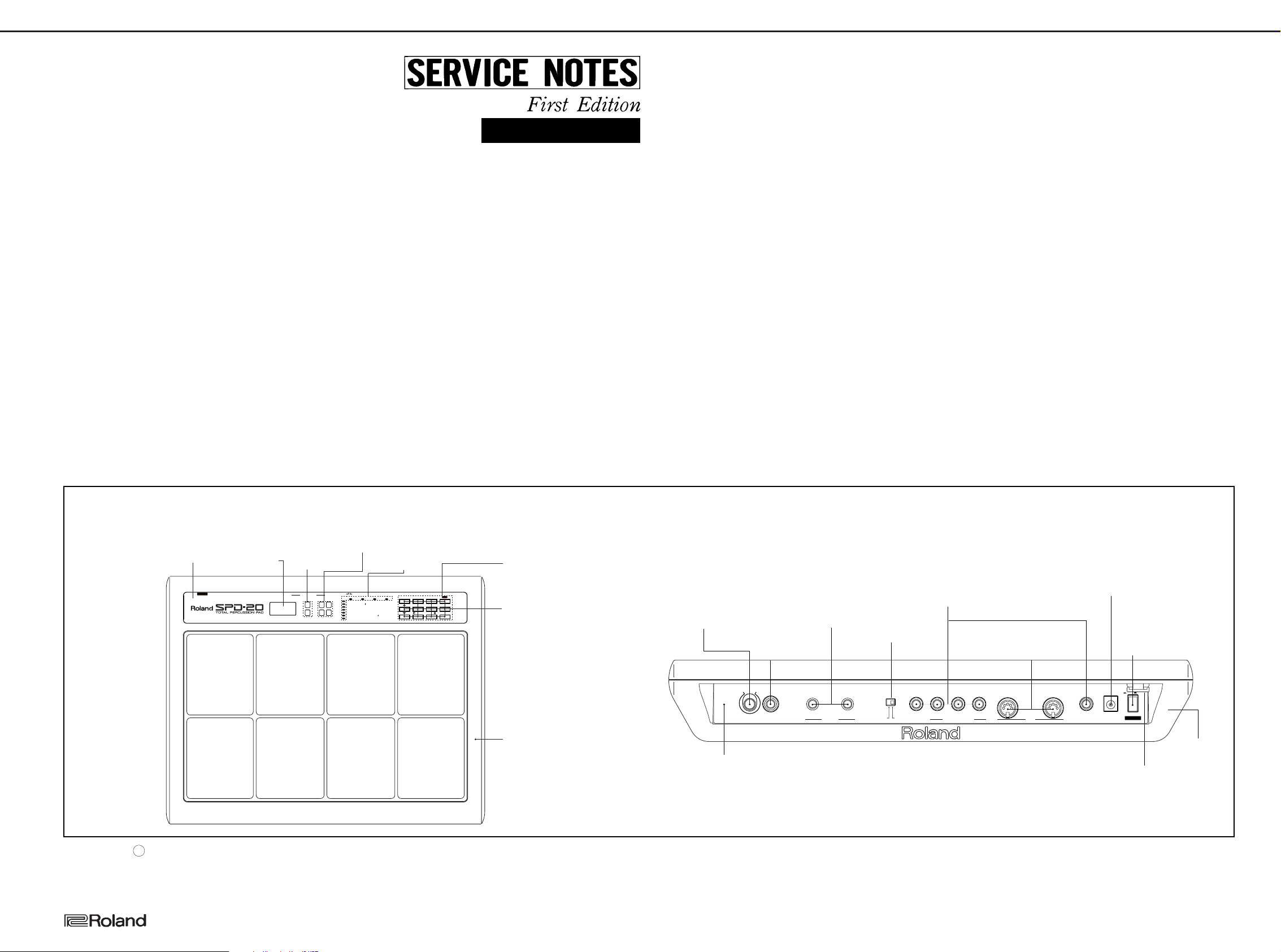
AC IN 1C IN 12V
FOOFOOT SWT SW
MIDI INMIDI IN
3
2
1
TRIGGER INPUTTRIGGER INPUT
HHHH
R
PHONESPHONES VOLUMEOLUME
INST
LEVEL
PITCH
DECAY
PAN
CURVE
FX SENDFX SEND
L(MONOMONO
)
HH CTHH CTRLRLMIDI OUTMIDI OUT
TX CHTX CH
NOTE
GT TIMEGT TIME
CURVE
SENS
PGM CHG PGM CHG
PAN
/TRIG 4RIG 4
TRIG 4TRIG 4
CTCTRLRL
BASIC CHASIC CH
BULK DUMPBULK DUMP
PATCH EXPTCH EXPAND
TRIG SENSTRIG SENS
TRIG TTRIG TYPE
TRIG THRESHOLDTRIG THRESHOLD
PDL CCPDL CC
FX TFX TYPE
FX TIMEFX TIME
FX LEVELFX LEVEL
PDL CTRLPDL CTRL
PDL LEVELPDL LEVEL
TRIG CURTRIG CURVE
POWER
Display Cover
(01453878)
7-SEG LED
LB-603VP (Red)
(15029567)
LED
SEL6410E-TP5(Green)
(00019523)
LED
SEL6210S-TP5(Red)
LED
(15039245)
LNJ802RPDJA (Red)
(01560689)
Rubber Switch
(01453901)
Switch
EVQ21304M
(13169761)
ABRev
Cho Fln
Dly
PAD BANK EFFECTS
SOUND MIDI FX/PEDAL SYSTEM SELECT
PATCH CHAIN
COPY
EDIT
BANK A/B
PATCH/VALUE
LAYER FX ON/OFF
ALL/ENTER
Jack (AC Adapter)
HEC0740-01-010
Power Switch
(13449728)
SPUN19430A
(13129369)
Key Top (Black)
(12499175)
Jack (Stereo)
YKB21-5006
(13449252)
DIN Socket
TCS5350-01-4151
(13429615)
Cord Hook
(22365708)
Slide Switch
SSSU14
(13159169)
Jack (Monaural)
HLJ7101-01-3010
(13449283)
Jack (Stereo)
HLJ7001-01-3010
(13449284)
Volume Knob
(22485109)
Rotary Volume
RK09L12B0 10KBX2
(13289228)
Bottom Case Assy
(71120101)
Rear Panel
(01453889)
USE BOSS BRA
ADAPTOR ONLY
POWER
ON/
OFF
500mA
AC IN 12V
FOOT SW
INOUT
MIN
MIDI
MAX
TRIGGER INPUT
123
/TRIG 4
HH CTRL
CTRL
PHONESVOLUME
L(MONO
)
R
OUTPUT
TRIG 4
HH
SPD-20
SPECIFICATIONS/主な仕様
SPD-20
total percussion pad
TABLE OF CONTENTS 目次 Page
SPECIFICATIONS ・・・・・・・・・・・・・・・・・・・・・・・・・・・・・ 主な仕様 ・・・・・・・・・・・・・・・・・・・・・・・・・・・・・・・・・・・・1
LOCATION OF CONTROLS ・・・・・・・・・・・・・・・・・・・・ パネル配置図 ・・・・・・・・・・・・・・・・・・・・・・・・・・・・・・・・1
EXPLODED VIEW ・・・・・・・・・・・・・・・・・・・・・・・・・・・・・ 分解図 ・・・・・・・・・・・・・・・・・・・・・・・・・・・・・・・・・・・・・・2
PARTS LIST ・・・・・・・・・・・・・・・・・・・・・・・・・・・・・・・・・・ パーツリスト ・・・・・・・・・・・・・・・・・・・・・・・・・・・・・・・・3
PANEL BOARD ASS'Y ・・・・・・・・・・・・・・・・・・・・・・・・・ PANELBOARDASS'Y・・・・・・・・・・・・・・・・・・・・・・・・4
VOLUME BOARD ASS'Y ・・・・・・・・・・・・・・・・・・・・・・・ BOLUMEBOARDASS'Y・・・・・・・・・・・・・・・・・・・・・・4
MAIN BOARD ASS'Y・・・・・・・・・・・・・・・・・・・・・・・・・・・ MAINBOARDASS'Y ・・・・・・・・・・・・・・・・・・・・・・・・・4
CIRCUIT DIAGRAM・・・・・・・・・・・・・・・・・・・・・・・・・・・・ 回路図 ・・・・・・・・・・・・・・・・・・・・・・・・・・・・・・・・・・5〜7
BLOCK DIAGRAM・・・・・・・・・・・・・・・・・・・・・・・・・・・・・ ブロック図 ・・・・・・・・・・・・・・・・・・・・・・・・・・・・・・・・・・8
LOADING THE FACTORY PRESET DATA・・・・・・・・
DATA SAVE AND LOAD・・・・・・・・・・・・・・・・・・・・・・・・ データのセーブとロードの方法 ・・・・・・・・・・・・・・・・8
INDENTIFYING THE VERSION NUMBER ・・・・・・・・ バージョン確認方法 ・・・・・・・・・・・・・・・・・・・・・・・・・・9
CHECKING BATTERY VOLTAGE・・・・・・・・・・・・・・・・ 電圧の確認方法(リチウム電池) ・・・・・・・・・・・・・・9
TEST MODE・・・・・・・・・・・・・・・・・・・・・・・・・・・・・・・・・・ テストモード・・・・・・・・・・・・・・・・・・・・・・・・・・・・・・・・10
ERROR MASSAGES ・・・・・・・・・・・・・・・・・・・・・・・・・・ エラー・メッセージ ・・・・・・・・・・・・・・・・・・・・・・・・・・13
HOW TO EXCHANGE THE SENSOR ASSY ・・・・・・ センサーASSY及びセンサーの交換方法・・・・・・・・・13
ADJUSTMENT ・・・・・・・・・・・・・・・・・・・・・・・・・・・・・・・・ 調整 ・・・・・・・・・・・・・・・・・・・・・・・・・・・・・・・・・・・・・・・・14
IC DATA・・・・・・・・・・・・・・・・・・・・・・・・・・・・・・・・・・・・・・ ICデータ ・・・・・・・・・・・・・・・・・・・・・・・・・・・・・・・・・・・・15
ファクトリー・プリセット・データのロード方法
IssuedbyRJA
・・・・・8
SPD-20 :TOTAL PERCUSSION PAD/トータル・パーカッション・パッド
●PADS / パッド
Built-in Pads / 内蔵パッド:8
External Pads(Option) / 外部パッド(別売):3(4)
●Maximum Polyphony / 最大同時発音数
14 Voices / 音
●Instruments / 音色数
700 Voices / 音
●Memory / メモリー
Patches / パッチ:99
Patch Chain / パッチチェイン:8
●Effect / エフェクト
Reverb / リバーブ
Delay / ディレイ
Chorus / コーラス
Franger / フランジャー
●Display / ディスプレイ
7-segment LED x3 / 7セグメントLEDx3
●Connectors / 接続端子
Output Jacks (L[Mono], R)
Phone Jack (Stereo) / ヘッドホン・ジャック(ステレオ)
Trigger Input Jacks (Dual):3
HH CTRL/TRIG 4 Jack (Dual)
MIDI Connectors (IN, OUT) / MIDI端子 (IN,OUT)
Foot SW Jack(Dual) / フットスイッチ・ジャック(デュアル)
*Trigger inputs 1 and 2 accept rim shots from the PD-7,PD-9 and PD-120 while inputs
3 and 4 accept rim shots from the PD-7 and PD-9.
※ PD-7,PD-9のリム・ショット奏法は全てのトリガー入力に対応していますが、
PD-120のリム・ショット奏法はトリガー入力1と2のみ対応しています。
/ アウトプット・ジャック (L(Mono),R)
/ トリガー入力ジャック(デュアル):3
/ HHCTRL/TRIG4ジャック(デュアル)
●Power Supply / 電源
AC 12V:AC Adaptor / AC12V:ACアダプター
●Current Draw / 消費電流
420mA
●Dimensions/ 外形寸法
17-3/4(W) x 13-13/16(D) x 2-13/16(H) inches
450(W)×350(D)×70(H)mm
●Weight / 重量
2.8 Kg / 6 lbs 3 oz(excepting AC adaptor)
/ 2.8kg(ACアダプターを除く)
●Accessories / 付属品
Owner's Manual / 取扱説明書
ENGLISH :(# 71121112)
JAPANESE :(# 71120089)
AC Adaptor (BOSS BRA Series)
100V :(# 12449621)
117V :(# 12449622)
230V :(# 01341356)
240V :(# 12449625)
Slit Tape / スリット・テープ:(#01564589)
保証書(国内のみ)
●Options / 別売品:
Pads (PD-120、PD-100、PD-9、PD-7、PD-5)
/ パッド (PD-120、PD-100、PD-9、PD-7、PD-5)
Kick Trigger Unit (KD-7)
/ キック・トリガー・ユニット(KD-7)
Hi-Hat Control Pedal (FD-7)
/ ハイハット・コントロール・ペダル(FD-7)
Footswitch (BOSS FS-5U) / フットスイッチ (BOSSFS-5U)
Footswitch Cable (BOSS PCS-31)
/ フットスイッチ・ケーブル(BOSSPCS-31)
Pedal Switch (DP-2/6) / ペダル・スイッチ(DP-2/6)
All-purpose Clamp Set (APC-33)
/ オール・パーパス・クランプ・セット (APC-33)
*In the interest of product improvement, the specifications and/or appearance of this
unit are subject to change without prior notice.
※ 製品の仕様および外観は、改良のため予告なく変更することがあります。
LOCATION OF CONTROLS/パネル配置図
Copyright c1998 by ROLAND CORPORATION
All rights reserved. No part of this publication may be reproduced in any form without the written permission of ROLAND CORPORATION.
本書の一部、もしくは全部を無断で複写・転載することを禁じます。
17059918
Printed in Japan (ACE0) (CR) 1
SPD-20
1
2
3
4
3X10mm Binding Head
P-tight Ni
3X10mm Binding Head
P-tight BZC x1
4X12mm Binding Head
P-tight Ni x15
M5X12mm Hex Socket
Bolt BZC x4
3X8mm Pan Head B-tight ZC
with Flat Washer x5
Head
B-tight
3X10mm Binding Head
P-tight Ni x4
3X8mm Binding head
P-tight BZC x8
3X6mm
B-tight
ZC with
Flat Washer
3X8mm Pan
x6
x3
5
6
7
9
11
13
14
15
16
17
16
18
8
10
Binding Head
ZC x4
3X10mm Binding Head
P-tight Ni
20
21
19
12
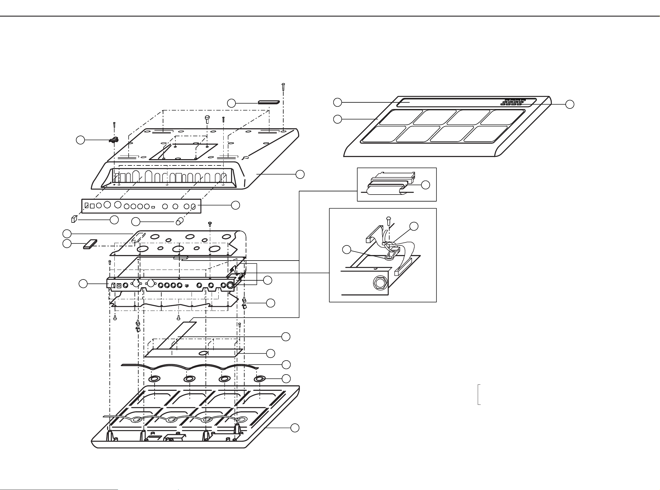
EXPLODED VIEW/分解図
Apr, 1998
q 22355152 Rubber Foot x 4
w 22365708 Cord Hook
e 71120101 Bottom Case Assy
NOTE :Replacement Bottom Case Assy includes the following parts.
注意: 補修用BottomCase Assyは、下記の部品を含みます。
q Rubber Foot
w Cord Hook
r Rear Panel
r 01453889 Rear Panel
t 12499175 Key Top (Black)
y 22485109 HP-5600 Knob
u 22255385 Shield Sheet
i 22265595 Shield Cushion
o 22205874 Rear Holder
!0 71120156 Main Board Assy
!1 12199573 PCB Holder x 2
!2 01560656 FUJI CARD
30 x 190 x A6.0 BB-P1.25-HBL15-S
!3 71120145 Panel Board Assy
!4 01455789 Sensor Flexible x 2
!5 25295208 ø27 Sensor Tape ø18 x 8
!6 71120090 Top Case Assy
Note: Replacement Top Case Assy consists of the following 5
parts. We don't supply Top Case, Playing Plate and
Cushion separatery.
注意: 補修用Top Case Assyは、下記の5部品で構成されます。
TopCaseAssy,PlayingPlate,Cushionのみの供給はありません。
******** Top Case
******** Playing Plate
******** Cushion
!7 01453878 Display Cover
!8 01453901 Rubber Switch
!9 12449471 Ferrite Core
@0 40016545 Tie Holder SKM-1
@1 40016512 Insulok Tie T-18S(80mm)
2
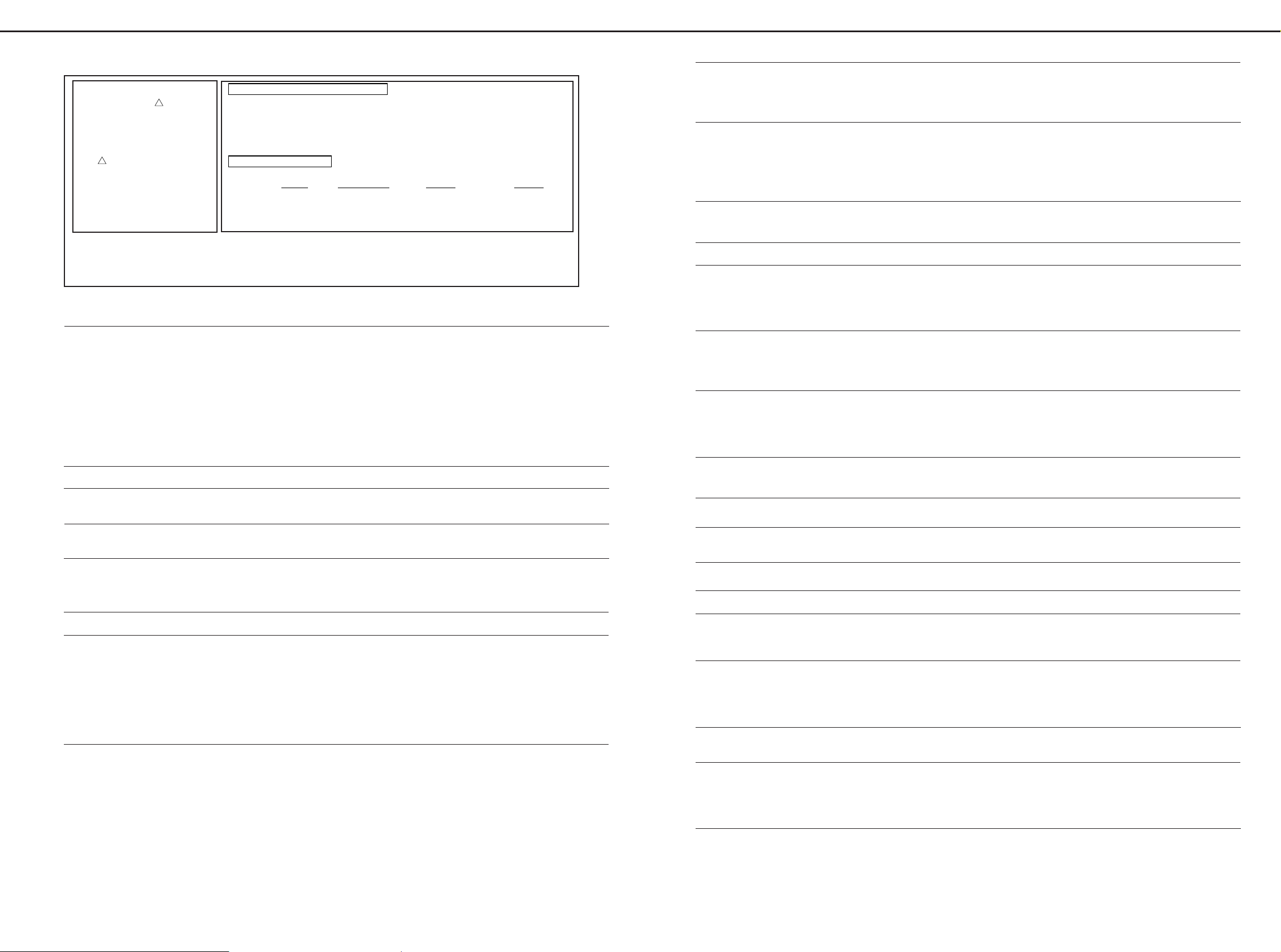
SAFETY PRECAUTIONS:*2
The parts marked have
safety-related characteristics.
Use only listed parts for
replacement.
安全上の注意:*2
が付いている部品は、安全上
特別な規格でつくられたもので
す。
交換の際は、注意をよく読み、
指定された部品番号以外の部品
は使わないようにして下さい。
!
!
CONSIDERATIONS ON PARTS ORDERING
When ordering any parts listed in the parts list, please specify the following items in the order sheet.
QTY PART NUMBER DESCRIPTION MODEL NUMBER
Ex. 10 22575241 Sharp Key C-20/50
15 2247017300 Knob (orange) DAC-15D
Failure to completely fill the above items with correct number and description will result in delayed or
even undelivered replacement.
パーツ発注に関するお願い
オーダーシートには、必ず下記の4項目は正確に記入して下さい。(例外は除く)
必要数 パーツナンバー 品 名 使用機種
例) 10 22575241 SharpKey C-20/50
15 2247017300 Knob(orange)DAC-15D
もし記入漏れ、誤記等が有る場合、必要部品が発送出来なかったり、大幅な遅れの原因になります。
御協力をお願いします。
Apr, 1998
SPD-20
PARTS LIST/パーツリスト
NOTE1:The parts marked # are new.(initial parts)
NOTE2:The parts marked ! have safety-related characteristics.
Use only listed parts for replacement
注意1:#が付いた部品は新規部品です。
注意2:!が付いた部品は安全上特別な規格でつくられた部品です。
交換の際は指定された部品番号以外の部品は使わないようにしてください。
MB / MAIN BOARD ASSY
PB / PANEL BOARD ASSY
VB / VOLUME BOARD ASSY
CASING/ケース
# 71120090 Top Case Assy
# 01453878 Display Cover
# 01453901 Rubber Switch
# 71120101 Bottom Case Assy
# 01453889 Rear Panel
CHASSIS/シャーシ
22205874 Rear Holder
KNOB, BUTTON/ツマミ、ボタン
# 01453901 Rubber Switch
12499175 Key Top for SDDWA(Black)
22485109 HP-5600 knob
SWITCH/スイッチ
13129369 SPUN19430A Power Switch SW2 on MB
13159169 SSSU14 Slide Switch SW1 on MB
13169761 EVQ21304M Tact Switch SW301 to 312
JACK, SOCKET/ジャック、ソケット
13429543 100-032-001 IC Socket 32P IC10 on MB
13449284 HLJ7001-01-3010 Jack(Stereo) JK401 on VB
13449283 HLJ7101-01-3010 Jack(Monoral) JK1,2 on MB
13449252 YKB21-5006 Jack(Stereo) JK3 to 6, 9 on MB
13449728 HEC0740-01-010 AC Adaptor Jack JK10 on MB
13429615 TCS5350-01-4151 MIDI Conector JK7,8 on MB
DISPLAY UNIT/表示ユニット
15029567 LB 603VP 7-seg LED D301 on PB
PCB ASSY/基板完成品
#‰ 71120156 Main Board Assy
# 71120167 Volume Board Assy
# 71120145 Panel Board Assy
IC/集積回路
15199776 h8/510 HD6415108F10 CPU IC12 on MB
00781723 M27C2001-10F1 2M EPROM(BLANK) IC10 on MB
17048914 M27C2001-10F1 2M EPROM(PROGRAMMED) IC10 on MB
15239229 TC6116AF(GP4) Custom IC IC6 on MB
# 01562756 LHMNOPW2 64M MASK ROM(for Sound) IC1 on MB
01122412 TC551001B(C)-70L SRAM IC8 on MB
01125112 TC55257DFL-70L(EL) SRAM IC3 on MB
15289125 PC410 Photo-Coupler IC17 on MB
15289709 M51954BFP SOP Reset IC IC22 on MB
15289714 uPD63200GS D/A Converter IC7 on MB1
15189261 M5218AFP Op. amp IC4,18,21,23,24,26,29,30 on MB
15289106 M5238FP Op. amp IC19 on MB
15289109 M5216FP Op. amp IC5 on MB
15259883 TC7S00F TE85L Single 2-input NAND Gate IC9 on MB
15249104 TC7S04F TE85L Single Inverter IC11,20 on MB
15249121 TC7W04F TE12L IC14 on MB, IC301 on PB
15259738T0 TC74HC138AF(EL) 3 to 8 Demultiplexer IC302 on PB
15259740T0 TC74HC139AF(EL) Dual 2 to 4 Demultiplexers IC303 on PB
15259864T0 TC74HC4052F-T2 Dual 4-channel Analog Multiplexer IC15,16 on MB
15259711T0 TC74HC14F-T2 Hex Schmitt Trigger Inverters IC13 on MB
# 15259742T0 TC74HC148AF(EL) 8 to 3 Priority Encoder IC2 on MB
15199291 BA9700A Switching Regulater IC28 on MB
15199231 uPC78L05J-T Regulater IC27 on MB
15199233 uPC79L05J-T Regulater IC25 on MB
Note: Replacement Top Case Assy consists of the following 5 parts.
We don't supply Top Case, Playing Plate and Cushion separately.
注意:補修用TopCaseAssyは、下記の5部品で構成されます。
TopCaseAssy、 PlayingPlate、Cushionのみの供給はありません。
******** Top Case
******** Playing Plate
******** Cushion
Note: Replacement Bottom Case Assy consists of the following 6 parts.
注意:補修用BottomCaseAssyは、下記の6部品で構成されます。
******** Bottom Case
22355152 Foot
22365708 PAD-80 Cord Hook
40011323 3*10mm Binding Head P-tight BZC
40019190 M5*12mm Hex Socket Bolt BZC
NOTE1: Replacement Main Board Assy includes the Rear Holder.
注意1:補修用 MainBoardAssyは、RearHolderを含みます。
NOTE2: Replacement Main Board Assy does not include the Litium Battery.
Because Litium Battery does not use for the back-up of factory presets.
注意2:MainBoardAssy上に装着されているリチウム電池は、工場出荷時の
データを保持する目的では使用されていません。MainBoardAssyを
オーダーしても、リチウム電池は装着されていませんので注意してください。
リチウム電池が必要な方は、別途オーダーしてください。
12569249S0 Litium Battery CR2032
TRANSISTOR/トランジスター
15319101 2SC2412KR T146 NPN Q23 to 27,29 to36, 38 to 42 on MB
15309101 2SA1037KR PNP Q1,2,28 on MB
15329507 DTA114EK T146 D-TR Q9 to 22 on MB
15329514 DTC343TK T146 D-TR Q3,6,7,8 on MB
15329105 2SK208Y TE85L N-ch FET Q4,5 on MB
15329516 DTC114EK T146 PNP Q301,302,303 on PB
15309605 2SB1184R F5 TR D-TR Q37 on MB
DIODE/ダイオード
15339138 DCC010-TB DA1,3,5,6,7,9 to 22 on MB
15339139 DCF010-TL DA4,8 on MB
15339140 DCG010-TL DA2 on MB
15339141 DSD010-TB D1,2,3,7 to 10,13,14 on MB D319 to 330 on PB
15039169 DSK10C-ET1 D4,5,11,12 on MB
00237712 RD5.6M-T1B B3 D6 on MB
# 01561301 1GWJ42 TPB2 D15 on MB
# 01560689 LNJ802RPDJA LED(red)
15039245 SEL6210S TP5 LED(red)
00019523 SEL6410E TP5 LED(gleen)
RESISTOR/抵抗
15399953 1W MCR100-220J 1W22Ω R12,34 on MB
15399931 MNR34J5ABJ221 R-ARRAY RA7,8 on MB
15399932 MNR34J5ABJ101 R-ARRAY RA1 to 5 on MB
15399965 RCE9A103JAG7A R-ARRAY R6 on MB
POTENTIOMETER/ボリューム
13289228 RK09L12B0 10KB *2 Rotary Volume VR401
CAPACITOR/コンデンサー
00674423 ECA0JM102B 1000uF/6.3V C151
13639698 ECEA0JKS101B 100uF/16V C3,4,6,7,29 to 33,42,68,72,102,110,115,121,130,140
13639150M0 ECEA0CKS100B 10uF/16V C1,2,4,5,25,26,27,28,128
13669261M0 ECEA1HKS010B 1uF/50V C98,143
13649710 25MV470HC+T 470uF/25V C119,139
13549260M0 ECQ-B1H272JF3 2700pF/50V C15,16
13549284 ECQ-B1H561JF3 560pF/50V C17,18
13559360 ECQ-B1181JF3 180pF/100V C13,14
POTENTIOMETER,TRIMMER/ボリューム
13299206 ENVD8AA03B24 VR1 on MB
01013556 RK09L1140 10KB VR4-7,14-17 on PB
# 01342545 RK09L1140 10KB with click VE3,13 on PB
01013545 RK09K12D0 10KBX2 VR1,2 on PB
# 01343301 RS25111A6 10KB L=15 25mm slide VR9-12 on PB
# 01343312 RS25111C6 10KB L=15 25mm clicked VR8 on PB
# 01342134 EWA NKE C10 B14 30mm slide VR18-25 on PB
CAPACITOR/コンデンサ
00236545 AMZV0050J224 0200 C120,127 on MB
00239601 AMZV0050J104 0200 C117,121,124,203,328,C333,335 on MB
# 00239434 AMZV0050J182 0200 C128,144,152,160,170,C330 on MB
00239490 AMZV0050J103 0200 C7 on PB
00236301 AMZV0050J222 0200 C123,135,147,156,165,C174 on MB
# 00239534 AMZV0050J223 0200 C122,129 on MB
# 00239578 AMZV0050J473 0200 C118,125,205 on MB
00236378 AMZV0050J822 0200 C202 on MB
INDUCTOR, COIL, FILTER/インダクタ、コイル、フィルター
12449396 BLM31A601SPT L3 on MB
00907856 BLM21A601SPT L1,2,4 to 28
00342556 ELC08D054 L29 on MB
12449471 SSC-45-8-F Ferrite Core
CRYSTAL, RESONATOR/クリスタル、発振子
00894023 MA-406 20.000MHz X2 on MB
# 01453945 SG8002DC 23.2MHz X1 on MB
CONNECTOR/コネクター
13429281 SLEM30R-2 CN2 on MB, CN301 on PB
# 01560678 SLD5R-1 CN3, 4 on MB
13369929 53253-0710 CN401 on VB
WIRING, CABLE/ワイヤリング、ケーブル
23505664 Wiring Harness A CN1 on MB
# 01560656 FUJI CARD 30*190-A6.0 BB-P1.25-HBL15-S FlatCable(30P)
BATTERY/電池
12569249S0 CR2032 220MAH 30M BT1 on MB
SENSOR/センサー
# 71120112 SENSOR ASSY
# ******** SPD-20 Sensor Flexible
SCREWS/ネジ類
40011245 4*12mm Binding Head P-tight NI
40011234 3*10mm Binding Head P-tight NI
40011312 3*8mm Binding Head P-tight BZC
40011034 3*8mm Pan Head B-tight ZC with Flat Washer
40011056 3*6mm Binding Head B-tight ZC
40011323 3*10mm Binding Head P-tight BZC
40019190 M5*12mm Hex Socket Bolt BZC
40016601 Nylon Ribet NRP-355
PACKING CASE/梱包材
# 01453890 PACKING CASE
22645349 PAD L
22645350 PAD R
MISCELLANEOUS/その他
12569420 Litium Battery Holder for CR2032
13429281 Connector SLEM30R-2 Flat Cable Holder(30P)
12199573 PCB Holder KGLS-8S
22255385 Shield Sheet
22175352 Leaf Spring
40016512 Inshlok Tie T18S 80mm
40016545 Tie Holder SKM-1
22265595 Shield Cushion
ACCESSORIES(STANDARD)/標準付属品
12449621 BRA-100 AC Adaptor(100V)
12449622 BRA-120 AC Adaptor(120V)
01341356 BRA-230 AC Adaptor(230V)
12449625 BRA-240A AC Adaptor(240V)
# 71121112 Owner's Manual English
# 71120089 Owner's Manual Japanese
# 01564589 Slit Tape Adhesive Tape White W3MM
NOTE: Replacement Sensor Assy consists of the following 2 parts.
注: 補修用SensorAssyは、下記の2部品で構成されます。
25295208 ø27 Sesor Tape ø18(*4)
3
SPD-20
For Nordic Countries
Apparatus containing
Lithium batteries
ADVARSEL!
Lithiumbatteri - Eksplosionsfare ved
fejlagtig håndtering.
Udskiftning må kun ske med batteri af
samme fabrikat og type.
Levér det brugte batteri tilbage til
leverandøren.
CAUTION!
Danger of explosion if battery is
incorrectly replaced.
Replace only with the same or
equivalent type recommended by
manufacture.
Discard used batteries according to the
manufacturer's instructions.
ADVARSEL!
Lithiumbatteri - Eksplosjonsfare.
Ved utskifting benyttes kun batteri som
anbefalt av apparatfabrikanten.
Brukt batteri returneres
apparatleverandøren.
VARNING!
Explosionsfara vid felaktigt batteribyte.
Använd samma batterityp eller en
ekvivalent typ som rekommenderas av
apparattillverkaren.
Kassera använt batteri enligt
fabrikantens instruktion.
VAROITUS!
Paristo voi räjähtää, jos se on
virheellisesti asennettu.
Vaihda paristo ainoastaan
laitevalmistajan suosittelemaan
tyyppiin. Hävitä käytetty paristo
valmistajan ohjeiden mukaisesti.
1 2 3 4 5 6 7 8 9 10 11 12 13 14 15 16 17 18 19 20 21 22 23 24 25 26 27 28
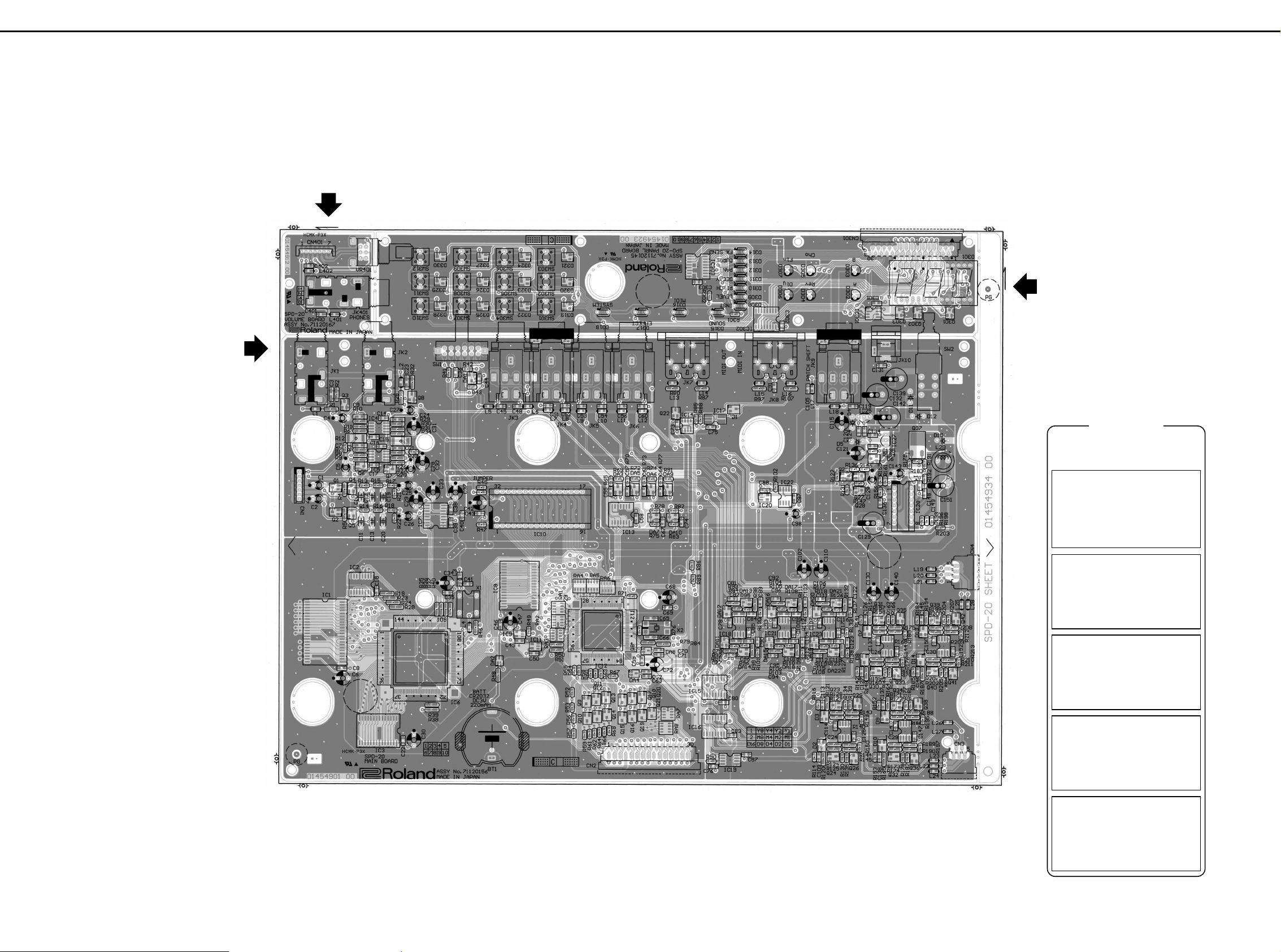
CIRCUIT BOARD/基板図
A
Apr, 1998
B
C
D
E
F
G
MAIN BOARD ASS'Y
ASSY 71120156
H
I
J
K
VOLUME BOARD ASS'Y
ASSY 71120167
PANEL BOARD ASS'Y
ASSY 71120145
L
M
N
O
P
Q
R
S
T
U
4
L/MONO
R
to CN 401
From BRA
AC 12V
NIU
VOLUME BOARD
SIDATA
BCLK
LRCK
Lch_OUT
Rch_OUT
Rch_RETURN
Lch_RETURN
PHONES_L
PHONES_R
XRESET
PHONES_R
PHONES_L
Rch_OUT
Rch_RETURN
Lch_RETURN
Lch_OUT
+
5D
D A A A
D
+
5A
A
A
+
5A
-
A5
A A A
+
5A
-
A5
+
5A
-
A5
A
A
A
A
AAA
A
A
AAA
+
5A
-
A5
A
A
A
A
A
A
A
+
5A
-
A5
A
-
5D
A A A
+
5D
DD
D
D
D
A
-
A5
A
+
5A
-
A5
AD
D
IC7
UPD63200GS
DVDD4AVDD7AVDD
8
LR/WDCK
13
CLK
16
SI/LSI
15
18/16
3
4/8FS
1
LRS/RSI
14
LOUT
11
ROUT
6
RREF
9
LREF
10
DGND
2
AGND5AGND
12
C39
0.1
C38
0.1
R18
10k
R16
10k
R14
10k
R22
56k
R5
390
Q2
2SA1037KR
1
3 2
Q5
2SK208Y
3
12
R17
10k
R15
10k
R13
10k
R21
56k
R4
390
Q1
2SA1037KR
1
2
Q4
2SK208Y
12
C2
10/16
C1
10/16
C25
10/16
C26
10/16
C37
100/6.3
C33
100/6.3
C29
100/6.3
R31
1k
IC4C
M5218AFP
8 4
C14
C15
0.1
R30
10k
R29
27k
C24
47p
C27
10/16
R25
1k
R32
56k
IC4B
M5218AFP
+
-
6
5
7
Q8
DTC343TK
1
23
L2
BLM21A601S
JK2
HLJ7101-01-3010
1
2
4
R6
1k
R11
10k
R10
27k
C9
47p
C4
10/16
R1
1k
R2
56k
IC4A
M5218AFP
+
-
2
3
1
Q3
DTC343TK
23
L1
BLM21A601S
JK1
HLJ7101-01-3010
1
2
4
R20
1k
R27
5.6k
R26 27k
R33
56k
C21 47p
Q7
DTC343TK
1
23
IC5B
M5216FP
+
-
6
5
7
IC5C
M5216FP
8 4
C16
0.1
R9
1k
R8
5.6k
R7 27k
R3
56k
C7 47p
Q6
DTC343TK
1
23
IC5A
M5216FP
+
-
2
3
1
JK10
HEC0740-010010
2
1
3
L29
ELC08D054
D15
1GWJ42
12
D11
DSK10C
1 2
D12
DSK10C
12
C139
470/25
C132
470/25
C142
470/25
C134
0.1
C124
0.1
C135
0.1
C120
0.1
C121
100/6.3
C115
100/6.3
IC27
UPC78L05J
IN
3
OUT
1
COM
2
IC25
UPC79L05J
IN
2
OUT
3
COM
1
Q28
2SA1037KR
1
32
Q27
2SC2412KR
1
23
Q25
2SC2412KR
23
R131
47k
R147
10k
R122
100k
R154
560
R146
47k
C128
10/16
R136
10k
R198
33k
R183
560
R179
560
C151 1000/6.3
R156 22k
R155
22k
R161 15k
C148
680p
C143 1/50
C136 1000p
C149
0.047
R192 6.8k
IC28
BA9700A
DTC
1
RT
2
CT
3
FB
4
OUT
5
NC
6
GND
7
VCC
8
NC
9
SW
10
VREF
11
-IN
12
1/2VREF
13
+IN
14
R193
15k
R196
10k
R191
47k
C23
1000p
C3
1000p
C5
10/16
C28
10/16
R34
1W22
R12
1W22
D5
DSK10C
12
D4
DSK10C
12
CN1
SPD-11 Wiring Harness A
1
1
2
2
3
3
4
4
5
5
6
6
7
7
SW2A
SPUN19-2N-W
12
11
13
C20
560p
C19
560p
C12
2700p
C13
2700p
C11
180p
C10
180p
SW2B
SPUN19-2N-W
22
21
23
C131
Q37
2SB1184RF5
1
23
C32
100/6.3
C31
100/6.3
D6
RD5.6M
13
C40
0.1
Apr, 1998
12345678910111213141516 17 18 19 20 21 22 23 24 25 26 27 28
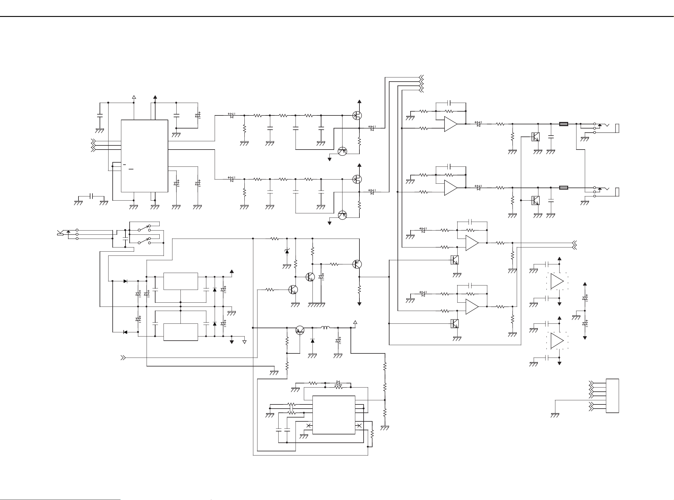
CIRCUIT DIAGRAM/回路図
A
B
SPD-20
C
D
E
F
G
H
I
J
K
L
M
N
O
P
Q
R
S
T
A A
1
D
A
3
3
1
0.1
+
0.1
A
C17
+
U
5

4M MASK :JUMPER
2M EPROM : R45
64M MASK ROM
GP_4
H8/510
NIU
MIDI IN
MIDI OUT
to CN 301 PANEL BOARD ASSY
FOOT SW
(SPD-20 WAVE)
WA22
WA21
WA20
MIDI OUT
D0
D1
D2
D3
D5
D6
D7
D0
D1
D2
D3
D4
D5
D6
D7
D4
D[0..7]
XWAIT
XRD
D7
D6
D5
D4
D3
D2
D1
D0
WA19
WA8
WA16
WA8
WA19
WA15
WA13
WA0
WA10
WA4
WA1
XWCS1
WA17
WA5
WA14
WA9
WA12
WA18
WA2
WA2
XWCS2
WA11
WA9
WA18
WA17
WA4
XWCS3
WA1
WA14
XWCS0
WA12
WA7
WA5
WA16
WA7
WA10
WA13
WA3
WA0
WA11
WA6
WA3
WA15
WA6
D0
D1
D2
D3
D4
D5
D6
D7
EA14
EA13
EA11
EA10
EA9
EA8
EA6
EA5
EA4
EA3
EA2
EA1
EA0
EA7
EA12
ED7
ED6
ED5
ED4
ED3
ED2
ED1
ED0
ED[0..7]
ED7
ED6
ED5
ED4
ED3
ED2
ED1
ED0
XEWR
XECS
WA[0..22]
WA20
XWCS3
XWCS2
XWCS1
XWCS0
XWCS[0..3]
WA22
WA21
XWCS
XWR
D0
D1
D2
D3
D4
D5
D6
D7
XWCS3
A5
A10
A1
A14
A14
A4
A14
A2
A7
A3
A10
A12
A11
A4
A3
A9
A9
A2
A9
A13
A12
A4
A20
A7
A8
A11
A[0..21]
A15
A8
A1
A0
A0
A16
A15
A0
A6
A6
A2
A0
A4
A8
A21
A5
A1
A13
A15
A11
A16
A5
A1
A13
A2
A7
A5
A10
A6
A12
A3
A19
A3
A17
A16
A17
A19
A20
A21
WD1
WD4
WD1
WD5
WD2
WD4
WD3
WD0
WD6
WD0
WD[0..7]
WD6
WD5
WD7
WD7
WD2
WD3
MIDI IN
HH_INIT
HH/TRG4_SW
SCAN_SW
RIM1
RIM2
RIM3
RIM4
SCAN_A
SCAN_B
XRESET
XRESET
SIDATA
BCLK
LRCK
XRESET
XRESET
+
5D
D
D
+
5D
+
5D
D
+
5D
+
5D
+
5A
D
D
D
+
5D
+
5D
+
5D
D
D
+
5D
+
5D
D
D
BAT
D
D
BAT
D
+
5D
D
D
+
5D
D
D
+
5D
+
5D
D
D
+
5D
D
+
5D
D
+
5D
D
+
5D
A
D
D
D
+
5D
+
5D
+
5D
+
5D
+
5D
D
+
5D
D
D
DD
+
5D
+
5D
D
+
5D
D
+
5D
+
5D
+
5D
D
+
5D
+
5D
+
5D
D
+
5D
D
D
D
A
A
D
+
5D
IC1
LHMN0PW2
A20
44
A19
43
A18
2
A17
3
A16
34
A15
35
A14
36
A13
37
A12
38
A11
39
A10
40
A9
41
A8
42
A7
4
A6
5
A5
6
A4
7
A3
8
A2
9
A1
10
A0
11
*/D15
31
BYTE
33
CE
12
OE
14
D14
29
D13
27
D12
25
D11
22
D10
20
D9
18
D8
16
D7
30
D6
28
D5
26
D4
24
D3
21
D2
19
D1
17
D0
15
A21
1
VCC
23
VSS
13
VSS
32
C6
100/6.3
C8
0.1
IC3
TC55257DFL-70L
A14
1
A13
26
A12
2
A11
23
A10
21
A9
24
A8
25
A7
3
A6
4
A5
5
A4
6
A3
7
A2
8
A1
9
A0
10
CE
20
WE
27
OE
22
I/O7
19
I/O6
18
I/O5
17
16
I/O4
I/O3
15
I/O2
13
I/O1
12
I/O0
11
VCC
28
VSS
14
JK8
TCS5350-01-4151
1
23459
10
JK7
TCS5350-01-4151
1
23459
10
L15
BLM21A601S
L16
BLM21A601S
L14
BLM21A601S
R97
100
R107
120
R87
220
C91
0.1
D1
DSD010
23
Q22
DTA114EK
32
IC14A
TC7W04F
17
IC14B
TC7W04F
IC14C
TC7W04F
62
C75
0.1
SLEM30R-2
1
2
3
4
5
6
7
8
9
10
11
12
13
14
15
16
17
18
19
20
21
22
23
24
25
26
27
28
29
30
Q21
DTA114EK
1
32
Q19
DTA114EK
1
32
Q17
DTA114EK
1
32
Q18
DTA114EK
1
32
Q15
DTA114EK
1
32
R203
10
Q20
DTA114EK
1
32
Q13
DTA114EK
1
32
Q14
DTA114EK
1
32
Q9
DTA114EK
1
32
Q11
DTA114EK
1
32
Q12
DTA114EK
1
32
R68
220
R66
220
R64
220
R62
220
R59
220
Q16
DTA114EK
1
32
C72
100/6.3
C59
0.1
X2
MA-406@
20.0MHz
1 4
R76
1M
IC22
M51954BFP
RST
6
DLY
VCC
GND
NC
NC
NC
NC
R84
100
R79
100
R71
10k
C69
0.1
C68
100/6.3
IC10
M27C2001-10F1
A18
31
A17
30
A16
2
A15
3
A14
29
A13
28
A12
4
A11
25
A10
23
A9
26
A8
27
A7
5
A6
6
A5
7
A4
8
A3
9
A2
10
A1
11
A0
12
CE
22
OE
24
D7
21
D6
20
D5
19
D4
18
D3
17
D2
15
D1
14
D0
13
VPP
VCC
32
VSS
16
C42
100/6.3
C43
0.1
JUMPER
R45
10k
R47
10k
RA5 100x4
1 8
2 7
3 6
4 5
RA4 100x4
1 8
2 7
3 6
4 5
RA1 100x4
1 8
2 7
3 6
4 5
RA2 100x4
1 8
2 7
3 6
4 5
RA3 100x4
1
2
3
4
IC9
TC7S00F
1
2
4
5 3
C49
0.1
TC551001B(C)FL-70 L
A16
A15
31
A14
A13
28
A12
4
A11
25
A10
23
A9
26
A8
27
A7
5
A6
6
A5
7
A4
8
A3
9
A2
10
A1
11
A0
12
CS2
30
CS1
22
WE
29
OE
24
I/O8
21
I/O7
20
I/O6
19
I/O5
18
I/O4
17
I/O3
15
I/O2
14
I/O1
13
NC
VDD
VSS
16
IC12
HD6415108F
49
112
111
110
109
96
95
94
93
80
79
78
77
76
75
74
73
72
71
70
69
68
67
66
65
86
85
84
83
87
82
92
91
90
89
54
53
52
51
50
98
99
2
63
62
61
60
59
58
57
56
45
44
43
42
41
40
39
38
36
35
34
33
32
31
30
29
28
27
26
25
24
23
22
21
19
18
17
16
15
14
13
12
11
10
9
8
7
6
5
4
107
104
105
106
103
1
48
47
102
101
55
88
108
3
203746648197100
C47
100/6.3
C46
0.1
IC11
TC7S04F
2 4
5 3
C50
0.1
C34
100/6.3
C35
0.1
R39
10k
R38
10k
R40
10k
X1
23.2MHz
SG-8002
OE
GND4OUT
5
VDD
8
C30
100/6.3
C22
0.1
IC2
TC74HC148AP
7
4
6
3
5
2
4
1
3
13
2
12
1
11
0
10
EI
5
A2
6
A1
7
A0
9
EO
15
GS
14
VCC
16
GND
8
C18
0.1
R57 10k
R56 10k
R53 10k
R52 10k
L17
BLM21A601S
L18
BLM21A601S
R82
47k
R78
47k
DA10
DCC010
2 1
3
DA7
DCC010
2 1
3
R83
1k
R75
1k
C74
100p
C67
100p
C73
0.1
L3
BLM32A601S
C41
0.1
C98
1/50
R102
4.7k
IC20
TC7S04F
2 4
5 3
C88
0.1
RA6
RCE9A@JA
10kx8
12
5
7
9
L4
BLM21A601S
R46
10k
R37 1k
R36 1k
R35 1k
R19 10k
IC14D
TC7W04F
8 4
R50
100
JK9
YKB21-5006
8
Q10
DTA114EK
1
32
R61
220
R55
10k
R54
10k
R58
10k
R60
10k
R63
10k
R67
10k
R51
2.2k
IC6
TC6116AF
185490
126
195591
104
127
142
114
113
112
66
67
69
68
70
71
74
73
76
80
75
77
79
81
84
86
85
87
89
93
95
94
92
88
99
100
78
72
97
102
107
115
111
110
109
108
101
116
98
82
83
118
117
52
96
53
56
57
65
64
63
62
61
60
59
58
103
105
46
47
48
49
50
51
106
134
135
137
136
138
139
141
140
4
7
2
144
143
1
3
5
6
8
9
11
45
42
43
36
33
38
40
41
39
37
35
34
32
30
28
29
27
25
23
21
22
24
26
119
121
120
122
123
R24 10k
R23 10k
R28 10k
R49
10k
R85
4.7k
C66
10p
C65
10p
DA4
DCF010
12
3
DA8
DCF010
12
3
C129
470/25
C105
1000p
C119
1000p
IC17
PC410
6 4
3
5
C97
0.1
R88
2.2k
SPD-20
A
B
C
D
E
F
G
H
I
J
K
L
M
N
O
P
Q
R
S
T
U
6
Apr, 1998
1 2 3 4 5 6 7 8 9 10 11 12 13 14 15 16 17 18 19 20 21 22 23 24 25 26 27 28
1
3
425
1
1
D
D
35
D
IC8
7
4
1
1
32
1
2
3
8
5
BAT
10
12
14
16
20
17
15
13
133
132
131
130
129
128
125
124
44
31
D
D
8
6
4
3
1
D
A
8
7
6
5
2
3
AN3
AN2
AN1
AN0
L13
R80
220
D
30
29
28
27
26
25
24
23
22
21
20
19
18
17
16
15
14
13
12
11
10
9
8
7
6
5
4
3
2
1
3
1
425
A
RA7
220x4
RA8
220x4
BLM21A601S
A
18
27
36
45
18
27
36
45
5
4
2
3
7
1
CN2

TRG1
TRG2
TRG3
TRG4/
HH_CTRL
to SENSOR ASSYto SENSOR ASSY
INTP4
INTP7
INTP5
INTP6
INTP3
INTP1
INTP8
INTP2
PAD7
PAD2
PAD6
PAD2
PAD8
PAD3
PAD5
PAD6
PAD5
PAD4
PAD7
PAD4
PAD1
PAD8
PAD3
PAD1
INTP1
INTP2
INTP3
INTP4
INTP5
INTP6
INTP7
INTP8
INTP[1..8]
PAD[1..8]
HH_INIT
RIM1
RIM2
RIM3
RIM4
AN0
SCAN_A
AN1
AN3
SCAN_B
AN2
HH/TRG4_SW
SCAN_SW
A A
+
5D
A A
A A
A A
+
5D
A A
A
A A
A
A
A A
A
A A
A
A A
A
A A
A
A A
A
D
+
5D
D
+
5D
D
+
5D
D
BAT
D
+
5A
A
+
5D
A
AA
+
5D
A
+
5D
A
A
A
DD
A
A
A
D
A
A
A
D
+
5D
A
A
D
+
5D
A
A
+
5D
+
5D
A
D
+
5D
-
5D
-
5D
D
A
A
A
A
A
A
+
5A
A
+
5A
A
A
A
+
5D
D
D
D
+
5D
D
D
+
5A
A
A
-
A5
+
5A
A
A
-
A5
+
5A
A
A
A
A
+
5A
-
A5
-
A5
A
+
5A
A -
A5
+
5A
A A
+
5A
-
A5
A
-
A5
D
D
+
5A
-
A5
-
A5
A
+
5A
-
A5
A
A A
A
A
A
A
A
A
A
-
A5
L12 BLM21A601S
C56
100p
C60
100p
L11BLM21A601S
R77
1k
R81
100k
IC13A
TC74HC14AF
1 2
L10 BLM21A601S
C53
100p
C54
100p
L9 BLM21A601S
BLM21A601S
C51
100p
C52
100p
L7 BLM21A601S
L6
BLM21A601S
C45
100p
C48
100p
L5
BLM21A601S
Q33
2SC2412KR
1
2 3
Q30
2SC2412KR
1
2 3
R159
27k
R160
18k
R167
27k
R170
5.6k
R163
1k
R169
5.6k
D8
DSD010
2 3
L21
BLM21A601S
R176
4.7k
Q35
2SC2412KR
1
2 3
Q31
2SC2412KR
1
2 3
R158
27k
R157
18k
R162
27k
R175
5.6k
R166
1k
R168
5.6k
D7
DSD010
2 3
L20
BLM21A601S
R180
4.7k
Q41
2SC2412KR
1
2 3
Q40
2SC2412KR
1
2 3
R201
27k
R202
18k
R206
27k
R211
5.6k
R205
1k
R210
5.6k
D14
DSD010
2 3
L28
BLM21A601S
R213
4.7k
Q42
2SC2412KR
1
2 3
Q39
2SC2412KR
1
2 3
R200
27k
R199
18k
R204
27k
R208
5.6k
R207
1k
R209
5.6k
D13
DSD010
2 3
L25
BLM21A601S
R212
4.7k
Q26
2SC2412KR
1
2 3
Q24
2SC2412KR
1
2 3
R124
27k
R125
18k
R135
27k
R145
5.6k
R130
1k
R144
5.6k
D2
DSD010
2 3
L22
BLM21A601S
R150
4.7k
Q29
2SC2412KR
1
2 3
Q23
2SC2412KR
1
2 3
R129
27k
R128
18k
R134
27k
R143
5.6k
R139
1k
R140
5.6k
D3
DSD010
2 3
L23
BLM21A601S
R149
4.7k
Q36
2SC2412KR
1
2 3
Q32
2SC2412KR
1
2 3
R173
27k
R174
18k
R182
27k
R190
5.6k
R178
1k
R189
5.6k
D10
DSD010
2 3
L27
BLM21A601S
R197
4.7k
Q38
2SC2412KR
1
2 3
Q34
2SC2412KR
1
2 3
R172
27k
R171
18k
R177
27k
R188
5.6k
R181
1k
R186
5.6k
D9
DSD010
2 3
L26
BLM21A601S
R195
4.7k
C64
0.047
R73
1k
R74
100k
IC13F
TC74HC14AF
13 12
C61
0.047
R70
1k
R72
100k
IC13E
TC74HC14AF
11 10
C57
0.047
R65
1k
R69
100k
IC13D
TC74HC14AF
9 8
C55
0.047
DA22
DCC010
2 1
3
R115
22k
R123
68k
R119
390k
C118
0.01
C123
0.22
R127
120k
R126
68k
DA21
DCC010
2 1
3
C116
0.01
C111 22p
R132
120k
C122
0.22
R110
68k
DA18
DCC010
2 1
3
R106
390k
R103
22k
C101
0.01
R109
120k
C104
0.22
R96
68k
DA14
DCC010
2 1
3
R92
390k
R91
22k
C86
0.01
R99
120k
C90
0.22
R95
68k
DA13
DCC010
2 1
3
R94
390k
R93
22k
C84
0.01
C82 22p
R98
120k
C89
0.22
DA12
DCC010
21
3
BT1
CR2032
12
R48
10k
R90
1M
C96 22p
R108
68k
R111
120k
DA17
DCC010
2 1
3
C103
0.22
C99
0.01
R116
100k
JK5
YKB21-5006
1
2
3
4
5
7
8
R164
180
R153
100k
JK3
YKB21-5006
1
2
3
4
5
7
8
R152
100k
IC23B
M5218AFP
+
-
6
5
7
R184
100k
IC26A
M5218AFP
+
-
2
3
1
C127
0.22
DA3
DCC010
2 1
3
IC26B
M5218AFP
+
-
6
5
7
R121
180
C87
0.1
IC30A
M5218AFP
+
-
2
3
1
R104
22k
IC18B
M5218AFP
+
-
6
5
7
R165
180
C126
0.22
R118
390k
DA20
DCC010
21
3
R185
100k
R105
390k
C146
0.22
IC30B
M5218AFP
+
-
6
5
7
C145
0.22
IC24A
M5218AFP
+
-
2
3
1
IC19C
M5238AFP
+
-
8 4
DA19
DCC010
21
3
IC18A
M5218AFP
+
-
2
3
1
C137
0.22
IC24B
M5218AFP
+
-
6
5
7
C109
0.22
R114
100k
C112 22p
IC29A
M5218AFP
+
-
2
3
1
IC21A
M5218AFP
+
-
2
3
1
C76
0.1
JK4
YKB21-5006
1
2
3
4
5
7
8
IC29B
M5218AFP
+
-
6
5
7
IC19B
M5238AFP
+
-
6
5
7
R113
100k
C79 22p
C113
0.22
DA11
DCC010
21
3
R187
180
IC23A
M5218AFP
+
-
2
3
1
C138
0.22
R194
180
C95 22p
DA2
DCG010
1 2
3
R120
180
R117
22k
DA15
DCC010
21
3
DA16
DCC010
21
3
IC19A
M5238AFP
+
-
2
3
1
DA6
DCC010
2 1
3
DA9
DCC010
2 1
3
R142
100k
R148
180
JK6
1
2
3
4
5
7
8
R89
100k
IC21B
M5218AFP
+
-
6
5
7
R141
100k
R151
180
DA5
DCC010
2 1
3
R112
100k
IC15
TC74HC4052AF
3Y
4
2Y
2
1Y
5
0Y
1
3X
11
2X
15
1X
14
0X
12
YCOM
3
XCOM
13
INH
6
B
9
A
10
VEE
7
VCC
16
GND
8
IC16
TC74HC4052AF
3Y
4
2Y
2
1Y
5
0Y
1
3X
11
2X
15
1X
14
0X
12
YCOM
3
XCOM
13
INH
6
B
9
A
10
VEE
7
VCC
16
GND
8
R138
100k
R101
100k
R43
10k
C44
0.01
R137
100k
R42
5.6k
R100
100k
DA1
DCC010
2 1
3
L24
BLM21A601S
L19
BLM21A601S
CN4
SLD5R-1
1
1
2
2
3
3
4
4
5
5
CN3
SLD5R-1
1
1
2
2
3
3
4
4
5
5
IC13B
TC74HC14AF
3 4
IC13C
TC74HC14AF
5 6
IC13G
TC74HC14AF
14 7
C58
0.1
SW1A
SSSF042-S06S0
12
11
13
SW1D
SSSF042-S06S0
42
41
43
SW1E
SSSF042-S06S0
20
10
R41
100k
SW1C
SSSF042-S06S0
32
31
33
SW1B
SSSF042-S06S0
222123
C36
100p
IC23C
M5218AFP
+
-
8 4
C107
0.1
C85
0.1
IC21C
M5218AFP
+
-
8 4
C93
0.1
C100
0.1
IC18C
M5218AFP
+
-
8 4
C78
0.1
C117
0.1
C133
0.1
C144
0.1
C152
0.1
C150
0.1
C125
0.1
C114
0.1
C141
0.1
C147
0.1
C83
0.1
C80
0.1
C62
22p
C63
22p
C70
22p
C71
22p
C102
100/6.3
C110
100/6.3
C130
100/6.3
C140
100/6.3
R86
100k
IC26C
M5218AFP
+
-
8 4
IC30C
M5218AFP
+
-
8 4
IC24C
M5218AFP
+
-
8 4
IC29C
M5218AFP
+
-
8 4
C108
0.22
C106
0.22
C94
0.22
C92
0.22
C77
0.22
C81
0.22
R133
120k
Apr, 1998
12345678910111213141516 17 18 19 20 21 22 23 24 25 26 27 28
A
SPD-20
B
C
D
E
F
G
H
I
J
K
L
M
N
O
P
Q
R
S
T
U
L8
YKB21-5006
A
A
A
A A
7

SPD-20
MIDI
IN
OUT
PHONES
L/MONO
R
AC IN
MAIN BOARD
PANEL BOARD
MIDI
FOOT
HH CTRL
VOLUME BOARD
TRIG 1-3
SW
SENSOR
ASSY
(PAD1-8)
/TRIG 4
TRIG 4
HH CTRL
12V
Power SW
SW 2
CPU
H8/510
SRAM
1Mbit
Program
ROM
2Mbit
Sound
Chip
WAVE
ROM
SRAM
256Kbit
DAC
LPF
AMP
Volume
1
IC12
IC10
IC8
IC1
IC1
IC3
IC7
+5VD
SW.RGL
D
IC8
IC10
MPX
+5VA
V.RGL
A
-5VD
V.RGL
Muting
IC18,21,23
IC13
D301
IC301,302B
Address Bus
Data Bus
Data
Address
Data
Address
-5VA
Compressor
Rim Sensor
IC24,26,29,30
Compressor
Decoder
IC302A,303
Decoder
A
A
A
A
A
AMP
AA
AA
Control
64Mbit
Buffer
A
IC 22
Reset IC
Reset
Reset
Q8
Q3
Q6
Q7
IC20
Muting
X2
20MHz
X'tal
X1
23.2MHz
OSC
Reset
SWx12
x11
x6
7-SEG LED
1
A0
A17
A20
AN3
AN0
P1-1
P1-0
RXD2
TXD1
P1-3
P1-2
P1-7
P1-4
P6-6
P6-0
P4-1
P4-0
P4-2
P4-7
P5-0
P5-5
D8
D15
P3-7
P3-5
P3-4
P3-1
A21
A19
CS
CS
CS
CK
Reset
Reset
74HC148
IC2
+
-+-
CS
A21,22
WCS3
0
3V
Litium
Battery
Apr, 1998
1 2 3 4 5 6 7 8 9 10 11 12 13 14
A
BLOCK DIAGRAM/ブロック図
B
C
D
E
F
G
H
I
J
K
L
M
N
O
P
LOADING THE FACTORY PRESET DATA
/ファクトリー・プリセット・データのロード方法
Perform this procedure after repairs or the like to restore
the RAM to its factory preset status.
This procedure will delete all data currently written to
RAM and replace them with the factory preset data.
1.Turn ON the power while pressing both the [
▼]
and[ALL/ENTER] keys at the same time.
The following display appears.
2.Press the [ALL/ENTER] key to execute initialization.
If initialization is unnecessary, press a key other than
the [ALL/ENTER] key.
本体を修理した後などこの操作を行い、RAMの内容をフ
ァクトリー・プリセットの状態に設定して下さい。この
操作を行うと、操作する前にRAMに書き込まれていたデ
ータは全て消去され、ファクトリー・プリセット・デー
タに置き換えられます。
1.[▼],[ALL/ENTER]キーを同時に押しながら電源
を投入します。
次のような表示が点滅します。
2.[ALL/ENTER]キーを押すとイニシャライズを実行
します。
操作を中止する場合は、[ALL/ENTER]キー以外のキ
ーをどれかひとつ押します。
DATA SAVE AND LOAD/データのセーブとロードの方法
To save the data stored in the RAM of the SPD-20 on an
external device or to load the external data onto the RAM
of the SPD-20, use the exclusive MIDI message.
The following explains how to transmit and receive the
data.
NOTE: In some devices, the MIDI channel number and
the Device ID number can be set independently,
and will not necessarily be the same. When
transferring bulk data with another device, refer to
the operating manual for that device.
<How to transmit (Bulk Dump) >
Here's how to transmit the mamory data of the SPD-
20.
Make connections between [MIDI OUT] of the
transmitter and [MIDI IN] of the receiver.
1.Set the Device ID number (=Basic Channel) on Which
Exclusive data will be sent.
SPD-20のRAMに記憶されているデータを他のSPD-20や
MIDI機器にMIDIのエクスクルーシブ・メッセージを使
用して送信・受信します。
以下にデータの送信、受信の方法を説明します。
注:MIDIチャンネルとデバイスIDを共有していない機種
もあります。他の機器を使用する場合は、機器の取
扱説明書を参照して下さい。
<送信(バルク・ダンプ)の方法>
SPD-20が記憶しているデータを、外部MIDI機器へ送
信します。
本体の[MIDIOUT]と受信側の[MIDI IN]とを接続しま
す。
1. まず、エクスクルーシブ情報を送るデバイスID(=ベ
ーシック・チャンネル)を設定します。
Q
R
S
T
U
8
1 In edit mode, press [SELECT] to select SYSTEM.
2 Use [▲], [▼] to select BASIC CH.
3 Use [▲PATCH/VALUE▼] to specify the channel (1~
16).
4 Press [EDIT] to return to play mode.
2. Use [▲], [▼] to select the SYSTEM parameter BULK
DUMP.
1 エディット・モードで[SELECT]キーを押して
"SYSTEM"を選びます。
2[▲],[▼]キーで"BASICCH"を選びます。
3[▲PATCH/VALUE▼]キーでチャンネル(1〜16)
を設定します。
4 [EDIT]キーを押してプレイ・モードに戻します。
2. [▲],[▼]キーでシステム・パラメータの"BULK
DUMP"を選びます。

Apr, 1998
SPD-20
3.Use [▲PATCH/VALUE▼] to select the patch data you
wish to transmit (ALL/1 ~ 99). If ALL is selected, all
Patch data, Patch Chain data, and system parameter
data will be transmitted at once.
4.Set the receiving MIDI device so that it will be able to
receive Exclusive messages.
5.Press [ALL/ENTER] and data transmission will begin.
<The time required of transmitting data>
All patch data ЧЧЧЧЧЧЧЧЧЧЧЧЧЧЧЧЧЧЧЧЧЧabout 65 sec
One patch dataЧЧЧЧЧЧЧЧЧЧЧЧЧЧЧЧЧЧЧabout a sec
If you wish stop the operation during transmission,
press [EDIT].
6.If you wish to transmit other Patch data, repeat steps 3
~ 5.
3.[▲PATCH/VALUE▼]キーで転送するパッチ(ALL/1
〜99)を選びます。
ALLを選ぶとすべてのパッチのデータ、パッチ・チェ
イン、システム・パラメータのデータをまとめて転送
します。
4. 受信側のMIDI機器をエクスクルーシブ・メッセージが
受信できる状態にします。
5. [ALL/INTER]キーを押すとデータの転送を開始します。
<データ転送時の所要時間>
すべてのパッチの転送ЧЧЧЧЧЧЧЧЧЧЧЧЧЧЧЧ約65秒
ひとつのパッチの転送ЧЧЧЧЧЧЧЧЧЧЧЧЧЧЧЧ約1秒
すべてのパッチのデータを転送している時、操作を中
断したい場合は[EDIT]キーを押します。
6. 他のパッチのデータを転送する場合は、3〜5を繰り
返します。
4.Press [EDIT] to return to play mode.
* Exclusive data transmission can require a significant
amount of time, so allow a reasonable time for these
operations. Data cannot be transmitted while incoming
Bluk data is being processed, nor can data be
received while Bulk data is being transmitted.
If Bulk data (Exclusive data) is received during Patch
Chain play mode, the SPD-20 will return to normal
play mode when reception ends.
4. [EDIT]を押してプレイ・モードに戻します。
※受信後処理に時間がかかる事があるので、連続送信す
る場合は、適当な時間間隔を置いて下さい。同様に、
受信したバルク・データの処理中は、データの送信が
できません。さらに、バルク・データの送信中は、デ
ータの受信ができません。
パッチ・チェインのプレイ中にバルク・データ(エク
スクルーシブ・データ)を受信した場合、受信後は通
常のプレイ・モードになります。
INDENTIFYING THE VERSION NUMBER/バージョン確認方法
The ROM version can be checked on the "Version check"
in "Test Mode".
However,if can also be checked with the following
procedure.
1. Trun ON the power supply while pressing both the
[SELECT] and [EDIT] keys at the same time. The
following will be displayed on the 7-segment LED.
The displayed ROM version number is for the EPROM (IC10 on CPU Board).
ROMのバージョンの確認方法は、「テスト・モード」中
の「バージョン確認」と同様にしても確認できますが、
次の方法でも確認できます。
1. [SELECT],[EDIT]キーを、同時に押しながら電源
を投入します。すると7セグメントLEDに下記のよう
に表示されます。表示されるROMのバージョンは、
EP-ROM(IC10onCPUBoard)のものです。
7.Press [EDIT] to return to play mode.
<How to receive (Bulk Load)>
Here's how to receive Patch data that was stored in
another SPD-20 or in a sequencer.
Make connections between [MIDI IN] of the transmitter
and [MIDI OUT] of the receiver.
NOTE: When data is received, the previous settings will
be lost.
1. Make sure that the MIDI channel of the transmitting
device matches the Basic channel of the receiving
SPD-20.
(refer to "How to transmit"-1)
If you transfer Exclusive data from another SPD-20,
set the basic channels on both units match.
If you receive the Exclusive data that was stored in a
sequencer, set the basic channel to match the same
number which was set when you saved data in the
sequencer.
2.Press [EDIT] to enter edit mode.
7. [EDIT]キーを押してプレイ・モードに戻します。
<受信(バルク・ロード)の方法>
他のSPD-20やシーケンサーなどに保存したパッチのデ
ータを受信します。
本体の[MIDIIN]と、送信側の[MIDI OUT]とを接続し
ます。
注:データを受信すると元のパッチの設定は書換えられ
てしまいます。
1. 送信側のMIDI機器からエクスクルーシブ情報を送るデ
バイスIDとSPD-20のベーシック・チャンネルを合わせ
ます。
(「バルク・ダンプの方法」1を参照。)
別のSPD-20からエクスクルーシブ情報を受け取るとき
は、2台のSPD-20を同じベーシック・チャンネルに設
定してください。また、シーケンサーなどに保存した
SPD-20のデータを読み込むときは、エクスクルーシブ
情報を送信したときと同じベーシック・チャンネルに
設定します。
2. [EDIT]を押してエディット・モードにします。
1.00 ЧЧЧЧЧЧЧЧЧЧЧЧЧЧЧЧЧversion number/バージョンナンバー
2.Press any key to the nomal mode.
2. どれか1つキーを押すと通常のモードに入ります。
CHECKING BATTERY VOLTAGE/電圧の確認方法
Use this procedure to check the voltage of the lithium
battery.
1.Holding down [
simultaneously, turn on power.
The LED display will show the status of the lithium
battery.
▲] and [FX ON/OFF] keys
リチウム電池の電圧の状態を確認します。
1.[▲]、[FXON/OFF]を同時に押しながら電源を投入し
ます。すると、下のように電圧が表示されます。
3.Transmit the Exclusive data from the other MIDI
device. When reception begins the following display
will appear.
3. 接続したMIDI機器からエクスクルーシブ・メッセージ
を送信します。
受信が始まると、パッチ・ディスプレイには次のよう
に表示されます。
The readings of 3.3 volts is a proof of a good battery
condition.
If the readings is below 2.2V, the battery needs an
exchange.
NOTE
:
The battery is also monitored during operation and
causes the error message if it goes below 2.2V.
(Refer to "ERROR MESSAGES" section.)
2.To return to the operation mode, press any key.
この場合、電圧は3.3Vであることを表しています。
2.2V以下はバッテリーの交換が必要です。
注:また、2.2V以下の場合は通常のモードでエラー・メ
ッセージが表示されます。
(エラーメッセージ参照)
2. 何かひとつキーを押すと、通常のモードに戻ります。
9

SPD-20
12L
R
TEST MODE/テストモード
Apr, 1998
< CAUTION >
The user data will be erased once the unit enters the
test mode.
Be sure to save the user data before accessing the
test mode. Refer to "DATA SAVE AND LOAD" section.
◎Tools and materials
• Monitor speakers
• MIDI cable
• Foot switches (FS-5U) x 2
• Connection cable (PCS-31)
• Pad (PD-7,PD-120)
• Monaural cable
• Hi-Hat control pedal (FD-7)
• Stereo cable
Make connections as shown in
following diagram.
下図のように接続します。
Red
PCS-31
MIDI Cable
/MIDIケーブル
FS–5U
White
<注意>
テストモードを実行すると、ユーザー・データーが
消去されてしまいますので、必ずデーターのセーブ
を行って下さい。データーのセーブ方法は、デー
ターのセーブ/ロードの方法を参照して下さい。
◎用意するもの
• モニター・スピーカー
• MIDIケーブル
• フットスイッチ(FS-5U)×2
• 専用ケーブル(PCS-31)
• パッド(PD-7,PD-120)
• モノラルケーブル
• ハイハット・コントロール・ペダル(FD-7)
• ステレオケーブル
Pad (PD–7,PD-120)
Monaural Cable
/モノラルケーブル
(Stereo cable
/ステレオケーブル
only PD-120)
This display is "TEST MENU".
If not all tests succeeded, the display shows as follows.
RAM NG:
WAVE ROM NG:
BATTERY NG:
fig. 2
この表示をメニュー表示画面と呼びます。
NGの場合下のような表示になます。
・RAM NGの場合
fig. 3
・WAVE ROM NGの場合
fig. 4
Battery NGの場合
IN OUT
SPD–20
FS–5U
Polarity Switch
/ポラリティースイッチ
Entering test mode
◎
While pressing [ALL/ENTER] and [EDIT] keys
simultaneously, turn power on.
The 7-seg LED will display as follows.
Monitor Speakers
/モニタスピーカ
◎テストモードの入り方
[ALL/ENTER]、[EDIT]キーを同時に押しながら、電源を
投入します。
すると下のように7セグメントLEDが表示します。
(The test mode is stoped.)
Exiting test mode
◎
Press [ALL/ENTER] key while in the test menu of the test
mode.The following display will qppear and it will blink.
After that SPD-20 exit the Test mode automatically.
Test procedure
◎
1.Version check
Press [SELECT] key, the 7-seg LED will display the
version number.
2.0V
fig. 5
注:NGの時エラーを表示して停止します。
◎テストモードの抜け方
メニュー表示の状態で[ALL/ENTER]キーを押します。す
ると下のような表示が現れ、点滅します。
その後、自動的にテストモードから抜けます。
fig. 6
◎各テストの説明
1.バージョン確認
[SELECT]キーを押すと下のように7セグメントLEDに
バージョンが表示されます。
Press [ALL/ENTER] key, RAM,SOUND ROM, LITHIUM
BATTERY check by
automatic operation, and the display shows as folloes:
10
fig. 1
その後、[ALL/ENTER]キーを押すとRAM、SOUND
ROM、リチウム電池チェックを
自動で行ないます。正常であれば下のような表示が現れ
ます。
fig.7 (1.00.....Version number)
Press [SELECT] key the display returns to the test menu.
もう一度[SELECT]キーを押してバージョン確認を終了します。
メニュー表示に戻ると下のような表示になっており、バ
ージョン確認が終了したことを表しています。

Apr, 1998
12 34
SPD-20
During the subsequent tests, the number of segments
being its is decremented by after returning to the menu
screen from a test.
2.LED check
Press [PATCH CHAIN] key to start the LED test.
Verify that all LED turn on, one at a time.
When all the segments have turned on, press [PATCH
CHAIN] key.
3.SW check
Press [COPY] key and the display changes as follows:
Press 12 keys on the right hand of the front panel one by
one.
Segments of the LED will be turned off, one at a time for
a key pressed.
When all keys are pressed, the 7-seg LED will show YES
fig. 8
その後、チェックが終わってメニュー表示に戻るたびに、
セグメントが一つずつ消えていきます。
2.LED check
[PATCH CHAIN]キーを押すとLED checkを開始しま
す。
各表示が順次点灯するので全て確認します。
確認したら、もう一度[PATCH CHAIN]キーを押してL
ED checkを終了します。
3.SW check
[COPY]キーを押すと下のような表示になります。
fig. 9
ここでパネル上にある12個のキーを押していくとセグメ
ントがひとつずつ消えてゆきます。
全てのキーが押されたら下のように7セグメントLED
にYESと表示され、自動的にメニュー表示に戻ります。
5.MIDI check
Connect the MIDI IN to MIDI OUT using the MIDI cable.
Press [▲] key to start the MIDI circuit test.
When the MIDI circuitry is good, the 7-seg LED shows
YES and returns to the menu.
6.TRIGGER INPUT check
Set TRIG4/HH CTRL selector switch on the rear panel to
TRIG4 position.
*TRIGGER CIRCUIT check
Hit head of PD-7 one by one and listen to the
speakers.Verify all jacks are correctly localized(panning).
SOUND NAME PAN
TRIG1 Kick hard left
TRIG2 Snare hard right
TRIG3 Darbuk hard left
TRIG4 Cymbal hard right
*RIM CIRCUIT check
Press [BANK A/B] key. The 7-seg LED will change as
follows:
5.MIDI check
MIDI checkに入る前に、MIDIケーブルでMIDI INとMIDI
OUTを結線して下さい。
[▲]キーを押すと下のような表示になり、自動的にMIDI
チェックを行ないます。
fig. 13
正常なら7セグメントLEDにYESと表示され、メニュ
ー表示に戻ります。
6.TRIGGER INPUT check
注:このとき、スライドスイッチは必ずTRIG4側にして
おきます。
*トリガー回路のチェック
パッド(PD-7)を結線して叩いてみて下さい。その時
つないだジャックによって、出力した音が違うこと
を確認します。
音色名 Pan
TRIG1 Kick 左
TRIG2 Snare 右
TRIG3 Darbuk 左
TRIG4 Cymbal 右
*リム回路のチェック
[BANK A/B]キーを押すと、下のような表示になり
ます。
and then return to the menu.
4.FOOT SW check
Connect FOOT SW socket to the foot switch via the
cable PCS-31.
Press [EDIT] key and the 7-seg LED will show:
Depress the pedals on the foot switch, one at a time.
As follows if the pressed pedal is good:
Then the 7-seg LED will show YES before returning to
the menu.
fig. 10
4.FOOT SW check
FOOTSWcheckに入る前に、SPD-20のFOOTSWJKとフ
ットスイッチを専用ケーブルPCS-31で接続して下さい。
[EDIT]キーを押すと、下のような表示になります。
fig. 11
ここでフットスイッチ1,2をそれぞれ押します。
正常ならば下のような表示になります。
fig. 12
その後YESと表示してメニュー表示に戻ります。
A monaural cable into TRIG1 ~ 4 jacks one by one.
As follows if this check is good:
Now the 7-seg LED should show YES and return to the
menu.
7.RIM A/D check
Press [LAYER] key. The 7-seg LED will change as
follows:
fig. 14
次にTRIG1〜4のジャックにひとつずつモノラル・ケーブ
ルを差し込んでいき、正常なら下のような表示になります。
fig. 15
その後、YESと表示してメニュー表示に戻ります。
7.RIM A/D check
[LAYER]キーを押すと下のような表示になります
fig. 16
11

SPD-20
5678
12 34
1234
5678
Apr, 1998
Connect TRIG1 jack to the PD-120 via the stereo cable.
Hit rim of the PD-120, the 7-seg LED will change as
follows:
Connect TRIG2 jack to the PD-120 via the stereo cable.
Hit rim of the PD-120, the 7-seg LED will change as follows:
Press [LAYER] key the display returns to the test menu.
8.Hi-HAT CONTROL check
Connect the Hi-Hat control pedal(FD-7) to SPD-20 HH
CTRL/TRIG4 socket via the monaural cable.
TRIG1ジャックにPD-120をステレオ・ケーブルで結線
し、RIM部分を叩くと下のような表示になります。
fig. 17
次にTRIG2ジャックにPD-120をステレオ・ケーブルで結
線し、RIM部分を叩きます。
fig. 18
正常であることを確認して[LAYER]キーを押し、メニュ
ー表示に戻ります。
8.Hi−Hat CONTROL check
ハイハット・コントロール・ペダル(FD-7)をモノラル・ケ
ーブルでSPD-20のHHCTRL/TRIG4と結線しておきます。
(The number of pad being checked on this display.)
Unlit segments indicate non-crosstalk pads and one
being checked.
After completion of the test, press[▼] key and the display
return to the test menu.
10.VELOCITY check
Press [-PATCH/VALUE] key. The 7-seg LED will change
as follows:
表示されている数字は、現在チェックしているパッドを示す。
fig. 22
クロストークしているパッドに対応したセグメントが点
灯しています。
チェック中のパッドに対応しているセグメントは点灯し
ません。
確認したら、[▼]キーを押してメニュー表示に戻ります。
10.VELOCITY check
[-PATCH/VALUE]キーを押すと、下のような表示が現れ
ます。
*Set HH CTRL/TRIG4 switch to HH CTRL.
Press [FX ON/OFF] key. The 7-seg LED will change as follows:
After entering the test mode, depress the control pedal.
The 7-seg will first read a value X(fluctuating) and should
read 0 at a maximum pressure.
Press [FX ON/OFF] key the display returns to the test
menu.
9.CROSSTALK check
Press [▼] key. The 7-seg LED will change as follows:
注:この時、スライドスイッチは必ずHH CTRL側にして
おきます。
[FXON/OFF]キーを押すと下のような表示になります。
fig. 19
テストモードに入った状態でペダルを踏むと、7セグメ
ントLEDにはその値が表示されます。ペダルを踏む強
さによって、その値が変化する事を確認して下さい。最
も強く踏み込んだときの値が0になります。
確認したら[FX ON/OFF]キーを押して、メニュー表示に
戻ります。
9.CROSSTALK check
[▼]キーを押すと下のような表示が現れます。
Press the head of the 8 pads on the SPD-20 and
observe the velocity readings on the LED display. The
highest readings should be 127.
After completion of the test, press[-PATCH/VALUE] key
and the display return to the test menu.
After completion of all tests, press [ALL/ENTER] key and
the 7-seg LED
returns to the operation mode after displaying message
shown in (fig.5).
fig. 23
SPD-20の8つのパッドを一つずつ叩いてゆくと、それぞ
れのベロシティーが表示されることを確認して下さい。
最大の値は127になります。
確認したら[-PATCH/VALUE]キーを押してメニュー表示
に戻ります。
最後に[ALL/ENTER]キーを押すと(fig.5)の表示のあと、
通常のモードになります。
The displayed number represents a pad. The [PATCH/VALUE+] keys scroll pads 1 through 8.
Hit the pad being displayed. No output sound means the
circuitry is good.
If the pad causes crosstalk sound, the display will
indicate:
12
fig. 20
表示されている数字はパッドを示していて、
[-PATCH/VALUE+]キーで1から8まで変化します。
この状態で、表示されている数字に対応しているパッド
を叩きます。
正常なら音は出ません。クロストークしている場合は、
音が鳴ると同時に下のような表示が現れます。
fig. 21

Apr, 1998
Sensor
Hollow
(To Decide The SENSOR Position)
センサー位置決め用凹
Top Case
3kg
2sec
Sensor
Top Case
ERROR MESSAGES/エラー・メッセージ
SPD-20
If a problem occurs during operation, an error message
will be displayed.
Check which error message is displayed, and take the
appropriate action as described in this section.
• The MIDI cable connecting another MIDI device to the
SPD-20 is not connected correctly or may be broken.
/Check the MIDI cable and the connections with the
other device.
• Balk Data loading was not successful.
/Try loading once again.
* Press any botton on the front panel and previous
display will reappear.
操作を誤ったり、正しく実行できなかった時は、7セグメ
ントLEDにエラー・メッセージが表示されます。
表示のエラー・メッセージを見て、以下の操作に従って
対処して下さい。
• 他のMIDI機器と接続しているMIDIケーブルがきちん
と接続されていないもしくは断線している
→MIDIケーブルの状態、他のMIDI機器との接続状態
を確認します。
• データのロードがうまくできなかった
→もう一度ロードします。
※パネル面のいずれかのボタンを押すと元の表示に戻
ります。
• This indicates that there is an irregularity in the voltage
of the pad detection circuit.
/IC15,IC16 or peripheral circuits may be at fault .
* Press any botton on the front panel and previous
display will reappear.
NOTE: Sometimes this error message will appear if you
strike a pad while turning on the power. In this
event, turn the power on once again.
• The memory backup battery inside the SPD-20 has
run down.
/Have the battery replanced.
* Press any botton on the front panel and previous
display will reappear.
• パッドの検出回路の電圧が異常である
→IC15,16及び周辺回路の異常である可能性があります。
※パネル面のいずれかのボタンを押すと元の表示にも
どります。
注:電源オン時にパッドを叩くとこのエラー・メッセー
ジが表示されることがあります。この場合はもう一
度電源を入れ直してください。
• SPD-20本体内のメモリー・バックアップ用の電池が消
耗している
→メモリー・バックアップ用の電池を交換します。
※パネル面のいずれかのボタンを押すと元の表示にも
どります。
• MIDI data was received incorrectly.
* Press any botton on the front panel and previous
display will reappear.
• Too much MIDI data was received from another MIDI
device.
/Reduce the amount of MIDI data transmitted by the
other device.
Or, retransmit the data after an interval to reduce the
amount of MIDI data transmitted in a short time.
* Press any botton on the front panel and previous
display will reappear.
• MIDI情報を正しく受信できなかった
※パネル面のいずれかのボタンを押すと元の表示に戻
ります。
• 他のMIDI機器から受信したMIDIデータの量が多すぎ
る
→他のMIDI機器が送信するMIDIデータの量を減らし
ます。
または時間をおいて送信し、一度に送信するMIDIデ
ータの量を減らします。
※パネル面のいずれかのボタンを押すと元の表示に戻
ります。
How to exchange the Sensor and the Sensor Assy
/センサーASSY及びセンサーの交換方法
1. Refer to the following for sticking positions of Sensor
Assys.
2.Press the Sensor Assy to an approximately 3-Kg load
for 2 seconds after stiking of the sensor assy.
1.
センサーを張り付ける位置は、下図を参照してください。
2. センサーを張り付けた後に3kgの加重を2秒間行って
ください。
• The memory data inside the SPD-20 has been lost.
/Press any button on the front panel. All data will be
initialized, and the normal display will reappear.
* If this happens, all the data in the SPD-20 will be
reset to the factory preset settings.
• SPD-20の内部のメモリー・データが壊れている
→パネル面のいずれかのボタンを押すとイニシャライ
ズを実行して、通常の表示に戻ります。
※この場合、SPD-20のデータはすべて工場出荷時の値
に設定されます。
13

SPD-20
ADJUSTMENT/調整
■
Preventing mistriggering of two pads tapped simultaneously
■
パッドを同時に叩いたときに発生する音抜けを緩和する方法
Apr, 1998
When you tap two internal pads simultaeously they may
positively trigger the sound. If this is the case, follow the
steps described below.
This information is not found in the Owner's manual.
1. Holding BANK A/B and LAYER, turn on the power
switch.
The display will read 70 which is the factory
setting.
2. This value is the "crosstalk cancel" level set for
the internal pads.
Change this value to 50 by pressing PATCH/VALUE [+] or [-].
Decreasing this value minimizes the chance of missing
sound but increases the chance of cross talk. *1 The
reverse holds true.
*1 Crosstalk: A tap of a pad will cause a different pad to
trigger its sound source.
A pad on the SPD-20 tends to cause crosstalk when it is
not tapped at the center.
8つの内部パッドのうち2つのパッドを同時に叩いたと
きの音抜けが気になる場合は、
次の設定をすることにより音抜けの症状を緩和する
ことができます。
この方法は、取扱説明書には記載されていない内容です。
以下の手順で設定を変更して下さい。
操作1: [BANKA/B]と [LAYER]を押しながら電源を
入れます。
ディスプレイに"70"と表示されます(70
が工場出荷時の設定です)。
操作2: PATCH/VALUE[-]、[+]いずれかのボタンを押
して"50"に設定します。
ここで設定する値は内部パッドの「クロストーク・キャ
ンセル」の値です。
この値を小さくすると、音抜けが少なくなりますがクロ
ストーク(*1)が起こりやすくなります。
逆にこの値を大きくすると音抜けは多くなりますがクロ
ストークが起こりにくくなります。
*1:クロストーク・・・パッドを叩いたときに他のパッ
ドの音が鳴ってしまう現象。
SPD-20 ではパッドの中心からはずれた場所を叩いたと
きに他のパッドにクロストークが起こることがありま
す。
Note: With the crosstalk cancel set at 50, strong tapping
of a pad at outer portion (from 2 cm from
periphery) will cause a crosstalk. Ask the user how
he plays the pads and adjust the cancel level in
the range of 60 to 70.
CAUTION: Pads are disabled during setting sequence of
the crosstalk cancel level.
3. Turn off power.
The setting is memorized and will be made effective as
you turn on the SPD-20 next time.
Remarks:
To set the crosstalk cancel level of the pads connected
to the TRIGGER INPUT of the SPD-20, refer to p.53 of
the Owner's manual.
Mistriggering is more likely to occur as two
pads are tapped at the same time and with
uneven forces (or out of the center of the pad).
To reduce mistriggering: Tap pads at the center
with same force; or not at the same time.
補足: クロストーク・キャンセル値を"50"に設定した
場合、パッドの中心からはずれた場所
(パッドの端から2cmぐらいまで)を強く叩
いたときに他のパッドとのクロストークが起こ
りやすく
なりますので、お客様の使用状況に応じて"60"
または"70"にする必要があります。
注意: 設定中にパッドで音を鳴らすことはできません。
操作3:電源を切ります。
これで設定が完了しました。次に電源を入れた時からこ
の設定が有効です。
補足: 2つのパッドを同時に叩くと音抜けが起こりやす
くなります。ややタイミングをずらして叩くと音
抜けは発生しません。また、2つのパッドを同時
に叩く場合でも、片方のパッドを弱く叩く
(または、中心からずれた場所を叩く)と音抜け
が起こりやすくなります。パッドの中心を同じ強
さで叩くと音抜けは起こりにくくなります。
*SPD-20のトリガー・インプットに接続した外部パッド
の「クロストーク・キャンセル」を設定する場合は取
扱説明書の P.53をご覧ください。
14

Photo Coupler(IC17 on MB)
PC-410
(15289125)
Oscillator(X1 on MB)
SG-8002
(01453945)
+5V Voltage Regulator(IC27 on MB)
µPC78L05J
(15199231)
Transistor(Q9 to 22 on MB)
DTA114EK (15329507)
Transistor(Q1, 2, 28 on MB)
2SA1037KR
(15309101)
Transistor(Q37 on MB)
2SB1184R F5
(15309605)
Transistor(Q23 to 27, Q29 to 36
2SC2412KR
(15319101)
FET(Q4, 5 on MB)
2SK208Y
(15329105)
-5V Voltage Regulator(IC25 on MB)
µPC79L05J
(15199233)
Transistor(Q301,302,303 on PB)
DTC114EK (15329516)
Transistor(Q3, 6, 7, 8 on CB)
DTC343TK (15329514)
Q38 to 42 on MB)
q Anode
e Cathode
r GND
t V0
y VCC
q 0E
r GND
t OUT q OUT
w GND
e IN
q Emitter
w Base
e Collector
i VDD
µPC78L05J
q GND
w IN
e OUT
µPC79L05J
q Emitter
w Base
e Collector
q Emitter
w Base
e Collector
q Drain
w Source
e Gate
q Base
w Collector
e Emitter
PB Panel Board Assy (pcb 22935470 2/3)
MB Main Board Assy (pcb 22935470 1/3)
ytr
eq
it
rq
weq
qw
e
qw
e
qw
e
qw
e
qwe
Apr, 1998
IC DATA/ICデータ
SPD-20
15
 Loading...