

Page 1
Owner’s Manual
Thank you, and congratulations on your choice of the Roland Sampling Workstation
SP-606.
201a
Before using this unit, carefully read the sections entitled: “USING THE UNIT
SAFELY” and “IMPORTANT NOTES” (p. 2–3; p. 4–6). These sections provide
important information concerning the proper operation of the unit. Additionally,
in order to feel assured that you have gained a good grasp of every feature
provided by your new unit, Owner’s manual should be read in its entirety. The
manual should be saved and kept on hand as a convenient reference.
202
Copyright © 2004 ROLAND CORPORATION
All rights reserved. No part of this publication may be reproduced in any form
without the written permission of ROLAND CORPORATION.
Page 2

USING THE UNIT SAFELY
Used for instructions intended to alert
the user to the risk of death or severe
injury should the unit be used
improperly.
Used for instructions intended to alert
the user to the risk of injury or material
damage should the unit be used
improperly.
* Material damage refers to damage or
other adverse effects caused with
respect to the home and all its
furnishings, as well to domestic
animals or pets.
001
• Before using this unit, make sure to read the
instructions below, and the Owner’s Manual.
................................................................................................
002c
• Do not open (or modify in any way) the unit
or its AC adaptor.
................................................................................................
003
• Do not attempt to repair the unit, or replace
parts within it (except when this manual
provides specific instructions directing you
to do so). Refer all servicing to your retailer,
the nearest Roland Service Center, or an
authorized Roland distributor, as listed on
the “Information” page.
................................................................................................
004
• Never use or store the unit in places that are:
• Subject to temperature extremes (e.g.,
direct sunlight in an enclosed vehicle, near
a heating duct, on top of heat-generating
equipment); or are
• Damp (e.g., baths, washrooms, on wet
floors); or are
• Humid; or are
• Exposed to rain; or are
• Dusty; or are
• Subject to high levels of vibration.
................................................................................................
007
• Make sure you always have the unit placed
so it is level and sure to remain stable. Never
place it on stands that could wobble, or on
inclined surfaces.
The symbol alerts the user to important instructions
or warnings.The specific meaning of the symbol is
determined by the design contained within the
triangle. In the case of the symbol at left, it is used for
general cautions, warnings, or alerts to danger.
The symbol alerts the user to items that must never
be carried out (are forbidden). The specific thing that
must not be done is indicated by the design contained
within the circle. In the case of the symbol at left, it
means that the unit must never be disassembled.
The ● symbol alerts the user to things that must be
carried out. The specific thing that must be done is
indicated by the design contained within the circle. In
the case of the symbol at left, it means that the powercord plug must be unplugged from the outlet.
008c
• Be sure to use only the AC adaptor supplied
with the unit. Also, make sure the line
voltage at the installation matches the input
voltage specified on the AC adaptor’s body.
Other AC adaptors may use a different
polarity, or be designed for a different
voltage, so their use could result in damage,
malfunction, or electric shock.
................................................................................................
009
• Do not excessively twist or bend the power
cord, nor place heavy objects on it. Doing so
can damage the cord, producing severed
elements and short circuits. Damaged cords
are fire and shock hazards!
................................................................................................
010
• This unit, either alone or in combination with
an amplifier and headphones or speakers,
may be capable of producing sound levels
that could cause permanent hearing loss. Do
not operate for a long period of time at a high
volume level, or at a level that is uncomfortable. If you experience any hearing loss or
ringing in the ears, you should immediately
stop using the unit, and consult an audiologist.
................................................................................................
011
• Do not allow any objects (e.g., flammable
material, coins, pins); or liquids of any kind
(water, soft drinks, etc.) to penetrate the unit.
2
Page 3
012c
• Immediately turn the power off, remove the
AC adaptor from the outlet, and request
servicing by your retailer, the nearest Roland
Service Center, or an authorized Roland
distributor, as listed on the “Information”
page when:
• The AC adaptor or the power-supply cord
has been damaged; or
• If smoke or unusual odor occurs
• Objects have fallen into, or liquid has been
spilled onto the unit; or
• The unit has been exposed to rain (or
otherwise has become wet); or
• The unit does not appear to operate
normally or exhibits a marked change in performance.
................................................................................................
013
• In households with small children, an adult
should provide supervision until the child is
capable of following all the rules essential for
the safe operation of the unit.
................................................................................................
014
• Protect the unit from strong impact.
(Do not drop it!)
................................................................................................
015
• Do not force the unit’s power-supply cord to
share an outlet with an unreasonable number
of other devices. Be especially careful when
using extension cords—the total power used
by all devices you have connected to the
extension cord’s outlet must never exceed the
power rating (watts/amperes) for the
extension cord. Excessive loads can cause the
insulation on the cord to heat up and
eventually melt through.
................................................................................................
016
• Before using the unit in a foreign country,
consult with your retailer, the nearest Roland
Service Center, or an authorized Roland
distributor, as listed on the “Information”
page.
................................................................................................
023
• DO NOT play a CD-ROM disc on a conventional audio CD player. The resulting sound
may be of a level that could cause permanent
hearing loss. Damage to speakers or other
system components may result.
101b
• The unit and the AC adaptor should be
located so their location or position does not
interfere with their proper ventilation.
................................................................................................
102d
• Always grasp only the output plug or the
body of the AC adaptor when plugging into,
or unplugging from, this unit or an outlet.
................................................................................................
103b
• At regular intervals, you should unplug the
AC adaptor and clean it by using a dry cloth
to wipe all dust and other accumulations
away from its prongs. Also, disconnect the
power plug from the power outlet whenever
the unit is to remain unused for an extended
period of time. Any accumulation of dust
between the power plug and the power
outlet can result in poor insulation and lead
to fire.
................................................................................................
104
• Try to prevent cords and cables from
becoming entangled. Also, all cords and
cables should be placed so they are out of the
reach of children.
................................................................................................
106
• Never climb on top of, nor place heavy
objects on the unit.
................................................................................................
107d
• Never handle the AC adaptor body, or its
output plugs, with wet hands when plugging
into, or unplugging from, an outlet or this
unit.
................................................................................................
108b
• Before moving the unit, disconnect the AC
adaptor and all cords coming from external
devices.
................................................................................................
109b
• Before cleaning the unit, turn off the power
and unplug the AC adaptor from the outlet
(p. 21).
................................................................................................
110b
• Whenever you suspect the possibility of
lightning in your area, disconnect the AC
adaptor from the outlet.
................................................................................................
118c
• Keep any screws you may remove and the
included card theft prevention cover in a safe
place out of children’s reach, so there is no
chance of them being swallowed accidentally.
3
Page 4

IMPORTANT NOTES
291a
In addition to the items listed under “USING THE
UNIT SAFELY” on page 2–3, please read and
observe the following:
Power Supply
301
• Do not connect this unit to same electrical outlet that
is being used by an electrical appliance that is
controlled by an inverter (such as a refrigerator,
washing machine, microwave oven, or air conditioner), or that contains a motor. Depending on the
way in which the electrical appliance is used, power
supply noise may cause this unit to malfunction or
may produce audible noise. If it is not practical to
use a separate electrical outlet, connect a power
supply noise filter between this unit and the
electrical outlet.
302
• The AC adaptor will begin to generate heat after
long hours of consecutive use. This is normal, and is
not a cause for concern.
307
• Before connecting this unit to other devices, turn off
the power to all units. This will help prevent
malfunctions and/or damage to speakers or other
devices.
Placement
351
• Using the unit near power amplifiers (or other
equipment containing large power transformers)
may induce hum. To alleviate the problem, change
the orientation of this unit; or move it farther away
from the source of interference.
352a
• This device may interfere with radio and television
reception. Do not use this device in the vicinity of
such receivers.
352b
• Noise may be produced if wireless communications
devices, such as cell phones, are operated in the
vicinity of this unit. Such noise could occur when
receiving or initiating a call, or while conversing.
Should you experience such problems, you should
relocate such wireless devices so they are at a greater
distance from this unit, or switch them off.
354a
• Do not expose the unit to direct sunlight, place it
near devices that radiate heat, leave it inside an
enclosed vehicle, or otherwise subject it to temperature extremes. Excessive heat can deform or
discolor the unit.
355b
• When moved from one location to another where
the temperature and/or humidity is very different,
water droplets (condensation) may form inside the
unit. Damage or malfunction may result if you
attempt to use the unit in this condition. Therefore,
before using the unit, you must allow it to stand for
several hours, until the condensation has completely
evaporated.
Maintenance
401a
• For everyday cleaning wipe the unit with a soft, dry
cloth or one that has been slightly dampened with
water. To remove stubborn dirt, use a cloth impregnated with a mild, non-abrasive detergent. Afterwards, be sure to wipe the unit thoroughly with a
soft, dry cloth.
402
• Never use benzine, thinners, alcohol or solvents of
any kind, to avoid the possibility of discoloration
and/or deformation.
Repairs and Data
452
• Please be aware that all data contained in the unit’s
memory may be lost when the unit is sent for
repairs. Important data should always be backed up
on a memory card, or written down on paper (when
possible). During repairs, due care is taken to avoid
the loss of data. However, in certain cases (such as
when circuitry related to memory itself is out of
order), we regret that it may not be possible to
restore the data, and Roland assumes no liability
concerning such loss of data.
Additional Precautions
551
• Please be aware that the contents of memory can be
irretrievably lost as a result of a malfunction, or the
improper operation of the unit. To protect yourself
against the risk of loosing important data, we
recommend that you periodically save a backup
copy of important data you have stored in the unit’s
memory on a memory card.
552
• Unfortunately, it may be impossible to restore the
contents of data that was stored on a memory card
once it has been lost. Roland Corporation assumes
no liability concerning such loss of data.
4
Page 5
553
CompactFlash™
• Use a reasonable amount of care when using the
unit’s buttons, sliders, or other controls; and when
using its jacks and connectors. Rough handling can
lead to malfunctions.
554
• Never strike or apply strong pressure to the display.
555
•A small amount of noise may be heard from the
display during normal operation.
556
• When connecting / disconnecting all cables, grasp
the connector itself—never pull on the cable. This
way you will avoid causing shorts, or damage to the
cable’s internal elements.
558a
• To avoid disturbing your neighbors, try to keep the
unit’s volume at reasonable levels. You may prefer
to use headphones, so you do not need to be
concerned about those around you (especially when
it is late at night).
559a
• When you need to transport the unit, package it in
the box (including padding) that it came in, if
possible. Otherwise, you will need to use equivalent
packaging materials.
562
• Use a cable from Roland to make the connection. If
using some other make of connection cable, please
note the following precautions.
• Some connection cables contain resistors. Do not
use cables that incorporate resistors for
connecting to this unit. The use of such cables can
cause the sound level to be extremely low, or
impossible to hear. For information on cable
specifications, contact the manufacturer of the
cable.
563
• Unauthorized duplication, reproduction, hiring, and
lending prohibited.
564
• Before you open the included CD-ROM, you must
read the “license agreement.” Opening the CD-ROM
will be taken to mean your acceptance of the license
agreement.
566b
• The sensitivity of the D Beam controller will change
depending on the amount of light in the vicinity of
the unit. If it does not function as you expect, adjust
the sensitivity as appropriate for the brightness of
your location.
985
• The explanations in this manual include illustrations
that depict what should typically be shown by the
display. Note, however, that your unit may incorporate a newer, enhanced version of the system (e.g.,
includes newer sounds), so what you actually see in
the display may not always match what appears in
the manual.
Before Using Cards
Using DATA Cards
704
• Carefully insert the DATA card all the way in—until
it is firmly in place.
705
• Never touch the terminals of the DATA card. Also,
avoid getting the terminals dirty.
707
• This unit’s memory card slot accepts CompactFlash
memory cards. Microdrive storage media are not
compatible.
708
• Memory cards are constructed using precision
components; handle the cards carefully, paying
particular note to the following.
• To prevent damage to the cards from static
electricity, be sure to discharge any static
electricity from your own body before handling
the cards.
• Do not touch or allow metal to come into contact
with the contact portion of the cards.
• Do not bend, drop, or subject cards to strong
shock or vibration.
• Do not keep cards in direct sunlight, in closed
vehicles, or other such locations (storage temperature: -25 to 85° C).
• Do not allow cards to become wet.
• Do not disassemble or modify the cards.
Handling CD-ROMs
801
• Avoid touching or scratching the shiny underside
(encoded surface) of the disc. Damaged or dirty CDROM discs may not be read properly. Keep your
discs clean using a commercially available CD
cleaner.
5
Page 6

Copyright
851
• Unauthorized recording, distribution, sale, lending,
public performance, broadcasting, or the like, in
whole or in part, of a work (musical composition,
video, broadcast, public performance, or the like)
whose copyright is held by a third party is
prohibited by law.
852b
• When exchanging audio signals through a digital
connection with an external instrument, this unit can
perform recording without being subjected to some
of the restrictions of the Serial Copy Management
System (SCMS). This is because the unit is intended
solely for musical production, and is designed not to
be subject to restrictions as long as it is used to
record works (such as your own compositions) that
do not infringe on the copyrights of others. (SCMS is
a feature that prohibits second-generation and later
copying through a digital connection. It is built into
MD recorders and other consumer digital-audio
equipment as a copyright-protection feature.)
853
• Do not use this unit for purposes that could infringe
on a copyright held by a third party. We assume no
responsibility whatsoever with regard to any
infringements of third-party copyrights arising
through your use of this unit.
204
* Microsoft and Windows are registered trademarks
of Microsoft Corporation.
206j
* Windows® is known officially as: “Microsoft®
Windows® operating system.”
207
* Apple and Macintosh are registered trademarks of
Apple Computer, Inc.
209
* MacOS is a trademark of Apple Computer, Inc.
213
* Pentium is a registered trademark of Intel Corpo-
ration.
220
* All product names mentioned in this document are
trademarks or registered trademarks of their
respective owners.
231
* OMS is a registered trademark of Opcode Systems,
Inc.
232
* FreeMIDI is a trademark of Mark of the Unicorn,
Inc.
233
* VST is a trademark of Steinberg Media Technologies
AG.
234
* CompactFlash and are trademarks of SanDisk
Corporation and licensed by CompactFlash association.
235
* Roland Corporation is an authorized licensee of the
CompactFlash™ and CF logo ( ) trademarks.
236
* Fugue © 2004 Kyoto Software Research, Inc. All
rights reserved.
6
Page 7

Contents
Main Features.....................................................................................................10
Conventions Used in This Manual....................................................................................................................... 11
An Overview of the SP-606 ...............................................................................12
How the Various Sections Are Connected.......................................................................................................... 12
Audio Signal Flow Inside the SP-606................................................................................................................... 12
How the SP-606 Is Organized............................................................................................................................... 13
Playing and Performing Sounds ............................................................................................................13
Switching the Mode (Internal/External) ..............................................................................................15
Top, Front, and Rear Panels .............................................................................16
Connecting the SP-606 to Your Equipment.....................................................20
Turning the Power On/Off .................................................................................21
Turning the Power On ........................................................................................................................................... 21
Shutting Down and Turning the Power Off....................................................................................................... 21
Inserting and Removing a Memory Card .........................................................22
Inserting a Memory Card ...................................................................................................................................... 22
Removing a Memory Card after Shutdown ....................................................................................................... 22
Quick Start..........................................................................................................23
Playing Samples from the Pads............................................................................................................................ 23
How to Play a Sample.............................................................................................................................. 23
Switching Pad Banks................................................................................................................................ 23
Adjusting the Loudness of the Sound When You Strike the Pads.................................................... 23
Playing Patterns...................................................................................................................................................... 24
Basic Procedure for Playing a Pattern ................................................................................................... 24
Selecting and Playing a Pattern from the Pattern List ........................................................................24
Changing the BPM (Tempo) During Pattern Playback ......................................................................25
Muting Individual Tracks .......................................................................................................................25
The Number of Samples That Can Be Played Simultaneously.......................................................... 25
Playing an Audio Input Signal ............................................................................................................................. 25
Recording Your Own Samples .............................................................................................................................26
Preparations for Sampling ......................................................................................................................26
Sampling.................................................................................................................................................... 27
Editing a Sample..................................................................................................................................................... 28
Looping a Sample..................................................................................................................................... 28
Changing How the Sample Plays and Stops........................................................................................ 28
Reversing the Playback............................................................................................................................ 29
Chapter 1. Playing the Pads/Making Pad Settings .........................................30
Playing the Pads .....................................................................................................................................................30
Playing a Roll ............................................................................................................................................ 30
Using the Sub Pad Function.................................................................................................................... 30
Using the Hold Function......................................................................................................................... 30
Making Pad Settings ..............................................................................................................................................31
Pad Bank Protect....................................................................................................................................... 31
Basic Procedure for Pad Utility Settings ............................................................................................... 31
Pad Utility Parameters............................................................................................................................. 31
Deleting a Sample..................................................................................................................................... 32
Using the Clipboard to Copy a Sample................................................................................................. 32
Chapter 2. Using Effects ...................................................................................33
Basic Effect Operation............................................................................................................................................ 33
Turning Effects On/Off........................................................................................................................... 33
Using the Control Knobs......................................................................................................................... 33
Choosing the MFX Type from a List ..................................................................................................... 33
7
Page 8

Contents
Selecting What the Effect Will Apply to (MFX Assign)...................................................................... 34
Making Mastering Settings ..................................................................................................................... 34
List of Effects ........................................................................................................................................................... 35
Chapter 3. Sampling ..........................................................................................42
Available Sampling Time ...................................................................................................................................... 42
Basic Sampling Procedure..................................................................................................................................... 43
Preparations for Sampling ......................................................................................................................43
Recording the Sample.............................................................................................................................. 44
Resampling.............................................................................................................................................................. 45
Applying an Effect While Resampling.................................................................................................. 45
Resampling (Automatic) .........................................................................................................................46
Resampling (Manual) ..............................................................................................................................47
Using EXT SEQ SAMPLING................................................................................................................................. 48
Sampling the Playback of an External Sequencer................................................................................ 48
Sampling a Performance from the P606................................................................................................ 49
Chapter 4. Editing a Sample .............................................................................50
Basic Procedure for Editing Sample Parameters................................................................................................ 50
Sample Parameters................................................................................................................................................. 50
Specifying the Start/End Points of a Sample (Omitting Unwanted Portions).............................................. 51
Changing a Sample’s BPM (Tempo).................................................................................................................... 52
Dividing a Sample (Chop)..................................................................................................................................... 53
Chapter 5. Creating a Pattern ...........................................................................54
About Pattern Recording....................................................................................................................................... 54
Realtime Recording ................................................................................................................................................ 54
Erasing Unwanted Performance Data................................................................................................... 55
Step Recording ........................................................................................................................................................ 56
Step Recording Note Procedure............................................................................................................. 56
Step Recording Sample Procedure......................................................................................................... 57
Chapter 6. Pattern Editing.................................................................................58
Preloaded Pattern Protect...................................................................................................................................... 58
Changing the Pattern BPM (Tempo) ...................................................................................................................58
Storing Track Mute Settings in a Pattern ............................................................................................................59
Microscope Editing ................................................................................................................................................ 59
Basic Procedure for Microscope Editing............................................................................................... 59
Inserting Performance Data (CREATE) ................................................................................................60
Erasing Performance Data (ERASE) ...................................................................................................... 60
Moving Performance Data (MOVE) ...................................................................................................... 60
Changing the Groove of a Pattern (SWING) ...................................................................................................... 61
Naming a Pattern.................................................................................................................................................... 61
Deleting a Pattern ................................................................................................................................................... 62
Copying a Pattern................................................................................................................................................... 62
Chapter 7. Songs ...............................................................................................63
Recording a Song.................................................................................................................................................... 63
Basic Procedure for Recording a Song ..................................................................................................63
Editing a Song ......................................................................................................................................................... 64
Basic Procedure for Editing a Song........................................................................................................ 64
Changing the Song BPM (Tempo) .........................................................................................................64
Naming a Song ......................................................................................................................................... 64
Deleting a Song......................................................................................................................................... 65
Copying a Song......................................................................................................................................... 65
Playing a Song......................................................................................................................................................... 65
Basic Procedure for Playing a Song ....................................................................................................... 65
Selecting and Playing a Song from the Song List ................................................................................66
Changing the Song Playback BPM (Tempo) ........................................................................................66
Muting Individual Tracks .......................................................................................................................66
8
Page 9

Chapter 8. Using a Memory Card .....................................................................67
Formatting (Initializing) a Memory Card ........................................................................................................... 67
Basic Procedure for Card Utility Operations...................................................................................................... 67
Card Utility Operations ......................................................................................................................................... 68
FILE IMPORT............................................................................................................................................ 68
FILE EXPORT............................................................................................................................................ 69
BACKUP SAVE......................................................................................................................................... 70
BACKUP LOAD .......................................................................................................................................70
BACKUP DELETE.................................................................................................................................... 71
Chapter 9. Using the D Beam............................................................................72
Using the D Beam Controller................................................................................................................................ 72
D Beam Controller Settings................................................................................................................................... 72
Basic Procedure for Making D Beam Settings......................................................................................72
D Beam Setting Parameters..................................................................................................................... 73
D BEAM INFO (D Beam Information) Screen .....................................................................................74
Chapter 10. About V-LINK .................................................................................75
What Is V-LINK? ....................................................................................................................................................75
Connection Example .............................................................................................................................................. 75
Basic V-LINK Operation........................................................................................................................................ 75
V-LINK Setup Parameters..................................................................................................................................... 76
Appendix .................................................................................................................................................................76
Controllable V-LINK Functions and MIDI Messages......................................................................... 76
Bank Select/Program Change Function List........................................................................................77
Chapter 11. Using the SP-606 with Other MIDI Equipment ............................78
About MIDI .............................................................................................................................................................78
About MIDI Connectors.......................................................................................................................... 78
About the MIDI Implementation Chart ................................................................................................ 78
MIDI on the SP-606................................................................................................................................................. 78
Changing the MIDI Settings .................................................................................................................................79
Basic Procedure for MIDI Utility Settings ............................................................................................79
MIDI Utility Parameters.......................................................................................................................... 79
Chapter 12. System Settings ............................................................................80
About the System Settings ....................................................................................................................................80
Using the Included CD-ROM to Restore the Factory-Set Condition................................................ 80
Making System Settings ..........................................................................................................................81
Checking System Information ................................................................................................................ 82
Adjusting the Master Level................................................................................................................................... 82
Chapter 13. About USB .....................................................................................83
Installing the USB Driver....................................................................................................................................... 83
Making the USB Connection................................................................................................................................. 83
USB Audio Signal Flow .........................................................................................................................................84
Making USB Audio and MIDI Settings............................................................................................................... 84
Copying Files or Folders via USB ........................................................................................................................ 85
Contents
Chapter 14. About P606.....................................................................................86
Installing P606......................................................................................................................................................... 86
Controlling P606 from the SP-606 ........................................................................................................................ 86
Before You Control P606 from the SP-606 ............................................................................................86
List of Control Functions......................................................................................................................... 86
Troubleshooting.................................................................................................87
Message Lists/Recommended Memory Cards................................................90
MIDI Implementation..........................................................................................92
MIDI Implementation Chart ...............................................................................96
Specifications.....................................................................................................98
9
Page 10

Main Features
Quick and easy sampling (p. 26, p. 42)
The SP-606 lets you use any of three sampling modes, whichever is most convenient for your situation.
SAMPLING
no need for settings or editing, sampling is quick and easy.
Sample from a variety of sources (p. 12, p. 84)
You can sample audio sources from the analog or digital inputs, or even via the USB connection, giving you the
flexibility to use any type of source.
Use the Chop function to automatically divide phrases (p. 53)
The SP-606 provides a Chop function, which automatically divides an audio phrase into several one-shot samples.
The divided samples can be rearranged randomly, combined, or used to create a virtually infinite number of
variations.
Velocity-sensitive pads are ideal for creating grooves (p. 23, p. 30)
The sixteen velocity-sensitive pads are a superb way to program grooves with natural-sounding dynamics, and
also offer great potential for realtime performance.
In addition, pad 16 can operate as a
played pad. This gives you much more freedom for performance expression, such as letting you use both hands to
play rolls or repeated notes.
makes it easy to capture a loop phrase of the appropriate length from an external MIDI device. With
Sub Pad
, which remembers and plays the same sound as the previously
EXT SEQ
Four-track pattern sequencer (p. 54)
In addition to realtime input, you can use two different step-input methods: the standard “
which you specify each note for input; and “
determines the timing of the next sample. These input methods accommodate a wide range of track-making
situations.
Step Rec Smpl
,” in which the length of the sample you input
Step Rec Note
BPM (tempo) sync capability (p. 52)
Any phrase sample can be freely made to follow the tempo of the internal sequencer. Since you can adjust the
BPM in real time without affecting the pitch, you can use samples in a whole new variety of ways.
Two independent multi-effects processors (p. 33)
Forty-five types
and also include unique effects such as “
used by either of the two multi-effects modules connected in series, giving you enormous potential for creative
sound-making. Intuitive knob-based control makes it easy to create bold and smooth changes in the sound.
of multi-effects range from familiar standards, such as spatial effects and distortion-type effects,
TAPE ECHO
” and “
LO-FI PROCESSOR
.” Any of these effects can be
Mastering effects for adding the finishing touch (p. 33)
Separately from the two multi-effects modules, a mastering effect module is provided to let you add finishing
touches at the final stage of your song, bringing it into a professional level of sound quality.
D Beam controller and V-LINK functionality (p. 72, p. 75)
The SP-606 features a D Beam controller, which lets you control a filter or solo synthesizer simply by moving your
hand. New realms of expression are made possible by V-LINK functionality, which lets you connect a compatible
video device and control it to create video effects that are linked to the expressive elements of a musical
performance.
,” in
10
Page 11

Use memory cards for easy expansion (p. 67)
A memory card slot is provided on the front panel. By inserting a commercially available 512 MB CompactFlash
card, you can perform up to 386 minutes of sampling (LONG mode, mono). There’s no need to load the data into
internal memory—data on the card can be accessed directly, even for playing from the pads. Even extremely large
samples can be handled quickly and freely.
USB connection to your computer (p. 83)
The SP-606 provides not only USB-MIDI functionality, but also file transfer capability for importing and exporting
.WAV and AIFF files. Audio drivers for WDM and ASIO are included, letting the SP-606 function as a versatile
USB audio interface (on Windows or Macintosh) with a variety of inputs and outputs.
Dedicated “P606” software for unlimited creation of loops (p. 86)
• The dedicated P606 software application developed by Cakewalk Corporation is included. P606
consists of three different sound generator modules, sophisticated multi-effects, and a sixteen-part
pattern sequencer and mixer—in other words, it’s a virtual groovebox!
• Phrases you create using P606 can be captured into the USB-connected SP-606 easily and quickly via
EXT SEQ SAMPLING
number of measures of the phrase, and makes the appropriate loop settings, meaning that you won’t
have to perform any bothersome processes after sampling.
• Of course the SP-606 also functions as a control surface for P606.
. The SP-606 automatically obtains the BPM (tempo), time signature, and
Main Features
Conventions Used in This Manual
Operating buttons are enclosed by square brackets [ ]; e.g., [ENTER].
Reference pages are indicated by (p. **).
The following symbols are used.
This indicates an important note; be sure to read it.
This indicates a memo regarding the setting or function; read it as desired.
This indicates a useful hint for operation; read it as necessary.
This indicates information for your reference; read it as necessary.
This indicates an explanation of a term; read it as necessary.
11
Page 12
An Overview of the SP-606
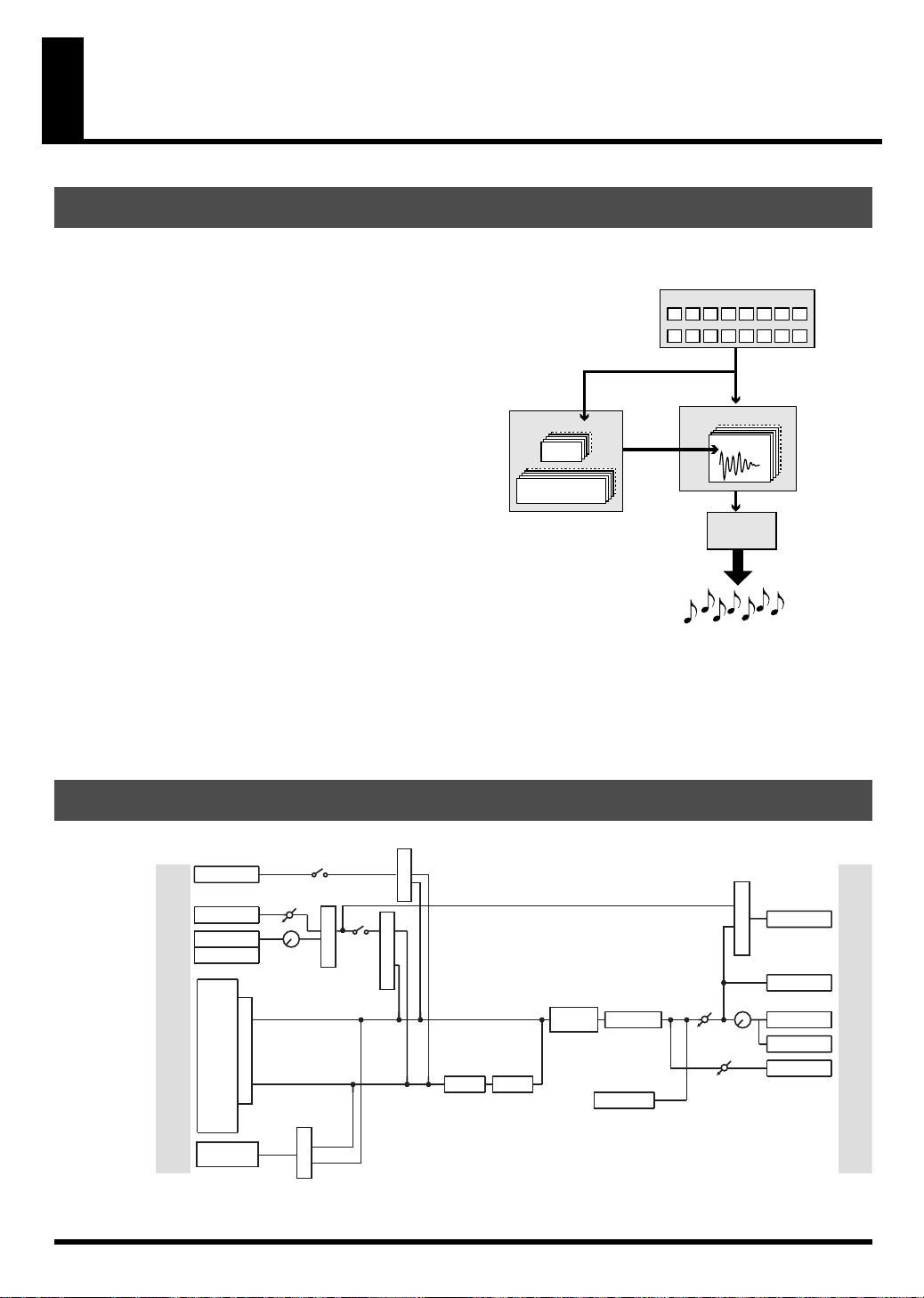
How the Various Sections Are Connected
fig.0G-1
Sampler
This records (samples) sounds, such as musical
performances or vocals, and plays back these
sounds.
Effects
This section applies various effects to the sampled
sounds (samples). You can choose from forty-five
different types of effect, such as “reverb” which
adds reverberation, and “lo-fi processor” which
intentionally degrades the audio quality of the
sound.
Pads
You can strike these pads to play the samples. You
can also vary the loudness of the sound by the
strength with which you strike a pad.
Sequencer
Pattern
Song
record
perform
automatically
Pads
Sampler
Sample
Effects
manual
play
Output
applies various
effects
Sequencer
This section lets you record the timing at which you
want samples to play, and specify how the samples
will be played. You can then play back this data to
create automatic performances.
Audio Signal Flow Inside the SP-606
fig.audioFlow
Digital In
Level
Audio In
Rec Level
Knob
MFX Assign
USB Input SW
Input Select
Send Select
Input
Source
MFX Assign
Input Send Select
MFX1
MFX2
* D BEAM
FILTER
USB
Digital
Line
Mic
Input
Sampler
* D BEAM
SYNTH
* You can use either D BEAM SYNTH or D BEAM FILTER (not both).
Mastering
Metronome
Master
Level
Volume
Sampling
Gain
USB Output SRC
Knob
USB
Digital
Line
Phones
Sampling
Output
12
Page 13
How the SP-606 Is Organized
An Overview of the SP-606
The SP-606 uses four types of data: “
“
songs
,” which contain performance data. In addition the SP-606 operates in one of two modes: “
in which you use the SP-606’s pads and knobs to control the SP-606 itself; and “
and knobs control the included P606 application running on your computer.
samples
Playing and Performing Sounds
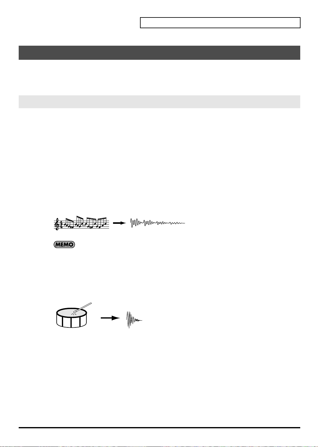
What Are Samples?
A sample is the most basic unit of audio material, consisting of a waveform (wave) that was created by sampling a
performance, instrumental sound, or voice, together with settings that specify how this waveform will be played
back. You can play the samples that are assigned to the pads, or play them from the internal sequencer or an
external sequencer.
There are two types of samples, which differ in the way that they are played back: phrase samples and single
samples.
Phrase Samples
In general, samples created by sampling a performance are called Phrase samples.
To use a sample as a phrase sample on the SP-606, set the sample’s “Play Type” (p. 50) parameter to
This causes the sample BPM (tempo) to automatically match the playback BPM or sequencer BPM.
This setting is appropriate for phrases that are one or several measures long.
fig.0G-2
Performance
Sampling
The sample BPM can be varied within the range from 0.5 through 1.3. If the sequencer BPM would
cause the sample BPM to exceed this allowable range, the sample BPM will be doubled or halved so
that it stays within this range.
Single Samples
On the SP-606, short samples (such as individual notes) are called Single samples. To use a sample as a single
sample, set its “Play Type” (p. 50) parameter to
length.
This setting is suitable for sounds that you use as single notes, such as drum hits or sound effects.
Phrase Sample
” and “
SINGLE
pad banks
,” which contain sounds; and “
external mode
. This causes the sample to always play at its original
patterns
internal mode
,” in which the pads
” and
PHRASE
”
.
Drum Sound
Sampling
Single Sample
13
Page 14
An Overview of the SP-606
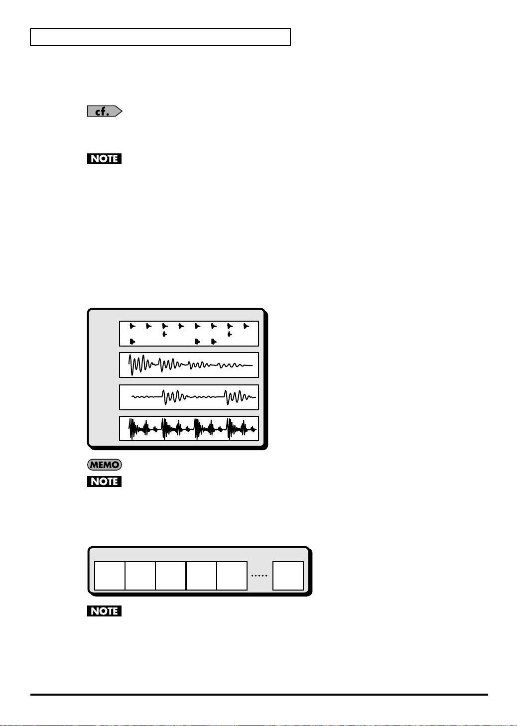
What Are Pad Banks?
A group of sixteen samples assigned to the pads of the top panel are collectively called a Pad Bank.
The SP-606 has thirty-two pad banks, letting you use a total of 512 samples.
About Pad Banks 1–8
When you sample into these banks, the samples will be saved in internal memory.
About Pad Banks 9–32
When you sample into these banks, the samples will be saved on a memory card.
What Are Patterns?
A pattern consists of 1–32 measures of performance (sequence) data that specifies the timing at which samples
will be played. Each pattern contain four “parts” (tracks), in which separate performances can be recorded.
You can select and play different patterns in succession, or create a song by specifying the order in which you
want patterns to play.
fig.0G-4
Pattern
Drum
Part
Refer to “Switching Pad Banks” (p. 23).
When the SP-606 is shipped from the factory, samples are already loaded into pad banks 1–4. Since
these samples are protected so that they will not be erased accidentally, you will be unable to edit or
delete them. If you want to disable protection for these samples, disable the pad bank protect setting
(p. 31).
(Hi-hat)
(Snare Drum)
(Bass Drum)
Bass
Part
Inst 1
Part
Inst 2
Part
A pattern can be up to 32 measures long.
The pattern simply specifies the timing at which the samples play; it does not contain the samples
themselves. This means that if you change the sample, the playback result will also change.
What Is a Song?
On the SP-606, an arrangement of multiple patterns in a desired playback order is called a Song.
fig.0G-5
Song
Pattern Pattern Pattern Pattern Pattern Pattern
Melody
Intro MelodyBMelodyAMelody
A
B
The song simply specifies the order in which patterns will play; it does not contain the sequence
data of the patterns themselves. This means that if you edit a pattern, the song playback will be
affected.
Ending
14
Page 15

Switching the Mode (Internal/External)
Internal
In this mode you can use the SP-606’s pads and knobs to control the SP-606 itself.
To select Internal mode, press
External
In this mode you can use the SP-606’s pads and knobs to control the P606 application (an included sequencer for
Windows) running on your USB-connected computer.
To select External mode, press
If you want to control both the SP-606 itself and the P606 application, press [INT] and [EXT] so both
buttons are lighted.
What Is the Play Screen?
The “play screen” refers to the screen that appears when you perform the following steps.
1. Power up the SP-606 as described in “Turning the Power On/Off” (p. 21).
2. Press [INT] so it’s lit.
At this time, [EXT] will be unlit.
3. Press [SONG] or [PTN].
If you press [SONG], the word “Song” will appear vertically at the left edge of the screen.
If you press [PTN], the word “Pattern” will appear vertically at the left edge of the screen.
[INT]
[EXT]
so it’s lit.
so it’s lit.
An Overview of the SP-606
Canceling the Previous Operation (Undo/Redo)
Before Recording/Editing
Recording/Editing
After Recording/Editing
REDO
UNDO
fig.0G-6
You can cancel the editing or recording operation that you
performed most recently on a song or pattern.
Procedure
Hold down [FUNC] and press [ ] (Top).
* You can execute Undo for Pattern (microscope edit, realtime
recording, step recording) and Song (edit, recording) operations.
* The Redo function cancels the Undo, returning you to the state before
executing Undo. After you’ve executed Undo, you can once again
hold down [FUNC] and press [ ] (Top) to execute Redo.
15
Page 16
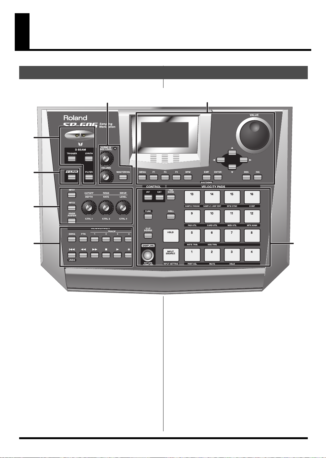
Top, Front, and Rear Panels
Top Panel
fig.top-panel
3
4
1
2
5
67
1
D BEAM controller
By placing your hand above this you can apply various
effects to a pattern or sample. (p. 72)
TRIGGER button
This lets you use the D Beam controller to play pads as an
alternative to striking the pads. (p. 72)
SYNTH button
This lets you use the D Beam controller to control the
pitch of a monophonic synthesizer. (p. 72)
16
FILTER button
This lets you use the D Beam controller to control a filter
that has an extremely steep slope. (p. 72)
2
V-LINK button
This turns V-LINK on/off. (p. 75)
Page 17
Top, Front, and Rear Panels
3
AUDIO IN REC LEVEL knob
This adjusts the volume of the audio signal that is input
via the rear panel INPUT (p. 19).
Adjust this knob so that the level indicator does not light.
(p. 26, p. 44)
VOLUME knob
This adjusts the volume of the audio signal that is output
from the rear panel OUTPUT and PHONES jacks (p. 19).
MASTERING button
This switches the mastering effect (used to add final
touches) on/off. (p. 33)
4
Screen
Various information is shown here according to the
operations you perform.
MENU button
You can press [MENU] to get the Top Menu screen.
F1, F2, F3 buttons
Various functions are assigned to these buttons
depending on the currently shown screen.
BPM button
This adjusts the BPM (tempo). (p. 25, p. 58, p. 64, p. 66)
5
MFX1 button
This switches MFX1 on/off. (p. 33)
MFX2 button
This switches MFX2 on/off. (p. 33)
KNOB ASSIGN button
This selects the MFX module controlled by the CTRL 1–3
knobs. (p. 33)
CTRL 1, CTRL 2, CTRL 3 knobs
These control effect parameters. (p. 33)
6
SONG button
This accesses the Song Play screen (p. 15).
PTN button
This accesses the Pattern Play screen (p. 15).
TRACK 1–4 buttons
These select the tracks for recording/playback. (p. 25,
p. 54, p. 59)
[] (Top)
Returns to the beginning of the song or pattern.
EXIT/ENTER buttons
These are used as Cancel (EXIT) or OK (ENTER) buttons
in various screens.
[][][][]
These move the cursor left/right/up/down in various
screens.
VALUE dial
Use this to adjust the value of a setting.
* You can hold down [FUNC] and turn the VALUE dial to make
larger changes in a value other than BPM (tempo).
DEC/INC buttons
These are used to change the value of a parameter
(setting) in steps of one.
* You can hold down [FUNC] and use [DEC][INC] to make
larger changes in a value other than BPM (tempo).
[] (Rewind)
Moves backward by one measure or one step.
[] (Fast-forward)
Moves forward by one measure or one step.
[] (Stop)
Stops playback.
[] (Play)
Starts playback.
[] (Record)
Records a pattern or song. (p. 54, p. 63)
17
Page 18
Top, Front, and Rear Panels
7
INT/EXT buttons
These buttons switch between Internal and External
modes. Normally you will leave Internal mode selected.
(p. 15)
FUNC button
You can hold down [FUNC] and press another button or
pad to access an alternate function for that button or pad.
CLIP BOARD button
This button lets you use the clip board to copy a sample.
(p. 32)
SAMPLING button
Use this button to perform sampling. (p. 26, p. 42)
Front Panel
fig.front-panel
PAD BANK button
Use this button to switch pad banks. (p. 23)
ROLL button
Use this button to play a roll. (p. 30)
HOLD pad
This pad activates the Hold function. (p. 30)
INPUT SOURCE pad
This pad sounds the audio input signal. (p. 25)
Pads [1]–[16]
You can play samples by striking these pads. (p. 23)
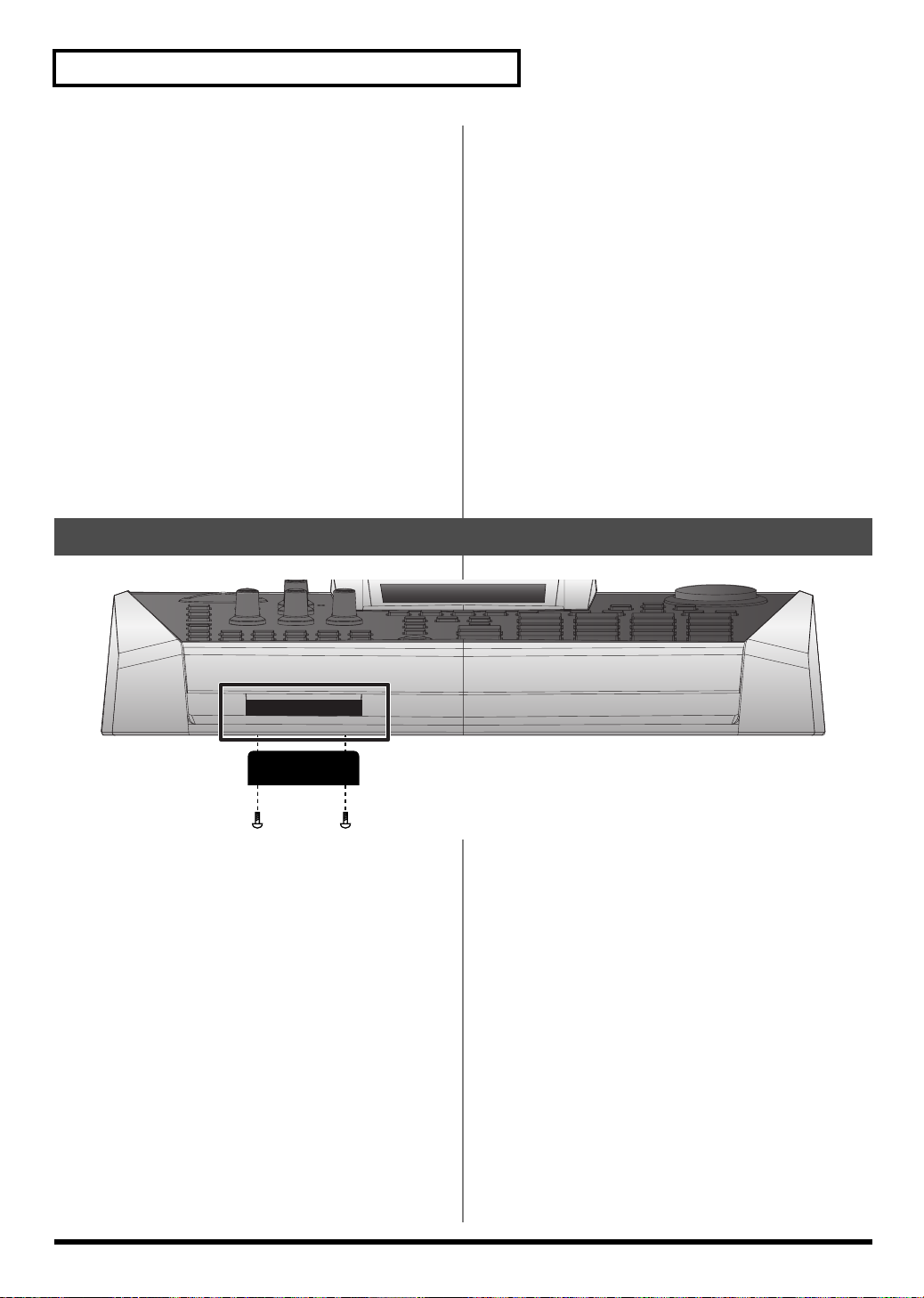
Memory card slot
You can insert a memory card here. (p. 22)
* You can use a Phillips screwdriver to remove the two screws
immediately under each end of the card slot (i.e., on the SP-
606’s bottom panel edge closest to yourself), and use these same
two screws to attach the included card theft prevention cover.
This will prevent the memory card from being removed and
stolen.
* When turning the unit upside-down, get a bunch of
newspapers or magazines, and place them under the four
corners or at both ends to prevent damage to the buttons and
controls. Also, you should try to orient the unit so no buttons
or controls get damaged.
* When turning the unit upside-down, handle with care to avoid
dropping it, or allowing it to fall or tip over.
18
Page 19

Rear Panel
fig.rear-panel
123 4 5 8 121169107
Top, Front, and Rear Panels
1. Cord hook
Use this to fasten the AC adaptor cable (p. 20)
2. Ground terminal
Depending on the circumstances of a particular setup,
you may experience a discomforting sensation, or
perceive that the surface feels gritty to the touch when
you touch this device, microphones connected to it, or the
metal portions of other objects. This is due to an
infinitesimal electrical charge, which is absolutely
harmless. However, if you are concerned about this,
connect the ground terminal (see figure) with an external
ground. When the unit is grounded, a slight hum may
occur, depending on the particulars of your installation.
If you are unsure of the connection method, contact the
nearest Roland Service Center, or an authorized Roland
distributor, as listed on the “Information” page.
Unsuitable places for connection
• Water pipes (may result in shock or electrocution)
• Gas pipes (may result in fire or explosion)
• Telephone-line ground or lightning rod (may be
dangerous in the event of lightning)
3. POWER switch
This turns the power on/off. (p. 21)
6. MIDI connectors (OUT/IN)
Use these to connect MIDI equipment. (p. 78)
7. DIGITAL jacks (OUT/IN)
Connect your audio source to the IN jack if you want to
sample via the digital input. Connect to the OUT jack if
you want to use digital output. (p. 20)
8. FOOT SWITCH jack
You can connect a foot switch (DP-2, BOSS FS-5U; sold
separately) to this jack. (p. 20)
9. INPUT jacks
Connect your audio source or microphone to this jack if
you want to sample via the analog input. If you’re
inputting a monaural source, connect it to the L (MONO)
jack. (p. 20)
10. OUTPUT jacks
These are analog output jacks. If you’re outputting in
monaural, use the L (MONO) jack. (p. 20)
11. PHONES jack
Connect a set of stereo headphones to this jack. Even if
headphones are connected, sound will still be output
from the DIGITAL OUT and OUTPUT jacks. (p. 20)
4. AC adaptor jack
Connect the included AC adaptor here. (p. 20)
5. USB connector
Use a USB cable to connect the SP-606 to your computer.
(p. 83)
12. Security slot ( )
http://www.kensington.com/
19
Page 20
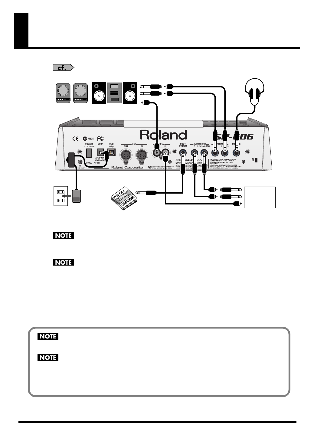
Connecting the SP-606 to Your Equipment
For details on USB connections, refer to “Chapter 13. About USB” (p. 83).
fig.connects
3
3
2
4
Refer to the diagram, and make connections according to the following procedure.
1.
Before you make any connections, switch off the power on all your equipment.
To prevent malfunction and/or damage to speakers or other devices, always turn down the volume,
and turn off the power on all devices before making any connections.
2.
Connect the included AC adaptor to the AC adaptor jack.
To prevent the inadvertent disruption of power to your unit (should the plug be pulled out
accidentally), and to avoid applying undue stress to the AC adaptor jack, anchor the power cord
using the cord hook, as shown in the illustration.
3
CD/MD Player
20
3.
Connect your audio system or amp(s) to the OUTPUT or DIGITAL OUT jacks. If you’re using headphones,
connect them to the PHONES jack.
If you intend to sample (p. 26, p. 42), connect your audio source device (e.g., CD player or mic) to the
DIGITAL IN
4.
Plug the AC adaptor into an AC outlet.
jacks.
When connection cables with resistors are used, the volume level of equipment connected to the
inputs (INPUT, DIGITAL IN) may be low. If this happens, use connection cables that do not contain
resistors, such as those from the Roland PCS series.
Howling could be produced depending on the location of microphones relative to speakers. This can
be remedied by:
1. Changing the orientation of the microphone(s).
2. Relocating microphone(s) at a greater distance from speakers.
3. Lowering volume levels.
INPUT
or
Page 21
Turning the Power On/Off
Turning the Power On
Once the connections have been completed (p. 20), turn on power to your various devices in the
order specified. By turning on devices in the wrong order, you risk causing malfunction and/or
damage to speakers and other devices.
1.
Turn the VOLUME knob all the way to the left to set the volume to the minimum position.
2.
Turn the volume of the connected amp or audio system to the minimum position.
3.
Press [POWER] to power up the SP-606.
This unit is equipped with a protection circuit. A brief interval (a few seconds) after power up is
required before the unit will operate normally.
4.
Power up the connected amp or audio system.
5.
While striking a pad to produce sound, adjust the volume by gradually raising the VOLUME knob.
Also raise the volume level of the connected amp or audio system to the appropriate level.
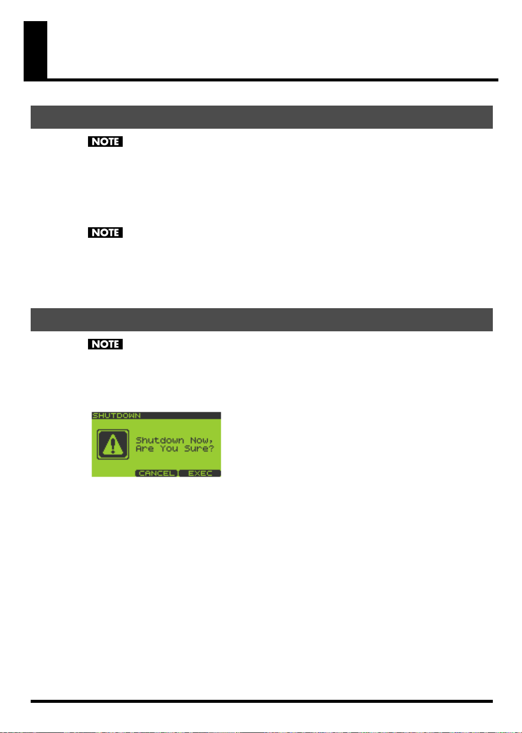
Shutting Down and Turning the Power Off
Before powering off the SP-606, you must first perform the shutdown operation. If you simply turn
off the power without shutting down, the data in internal memory or the memory card may be
damaged.
1.
Go to the Play screen (p. 15).
2.
Hold down [FUNC] and press [EXIT] (SHUTDOWN) to get the SHUTDOWN screen.
3.
Press [F3] to shut down.
When you have returned to the Play screen, it is safe to switch off the power.
If you decide not to shut down, press [F2] (CANCEL).
4.
Lower the volume on the SP-606 and all your external equipment so they’re at the lowest possible level.
5.
Switch off all your external equipment.
6.
Press [POWER] to switch off the SP-606’s power.
21
Page 22
Inserting and Removing a Memory Card
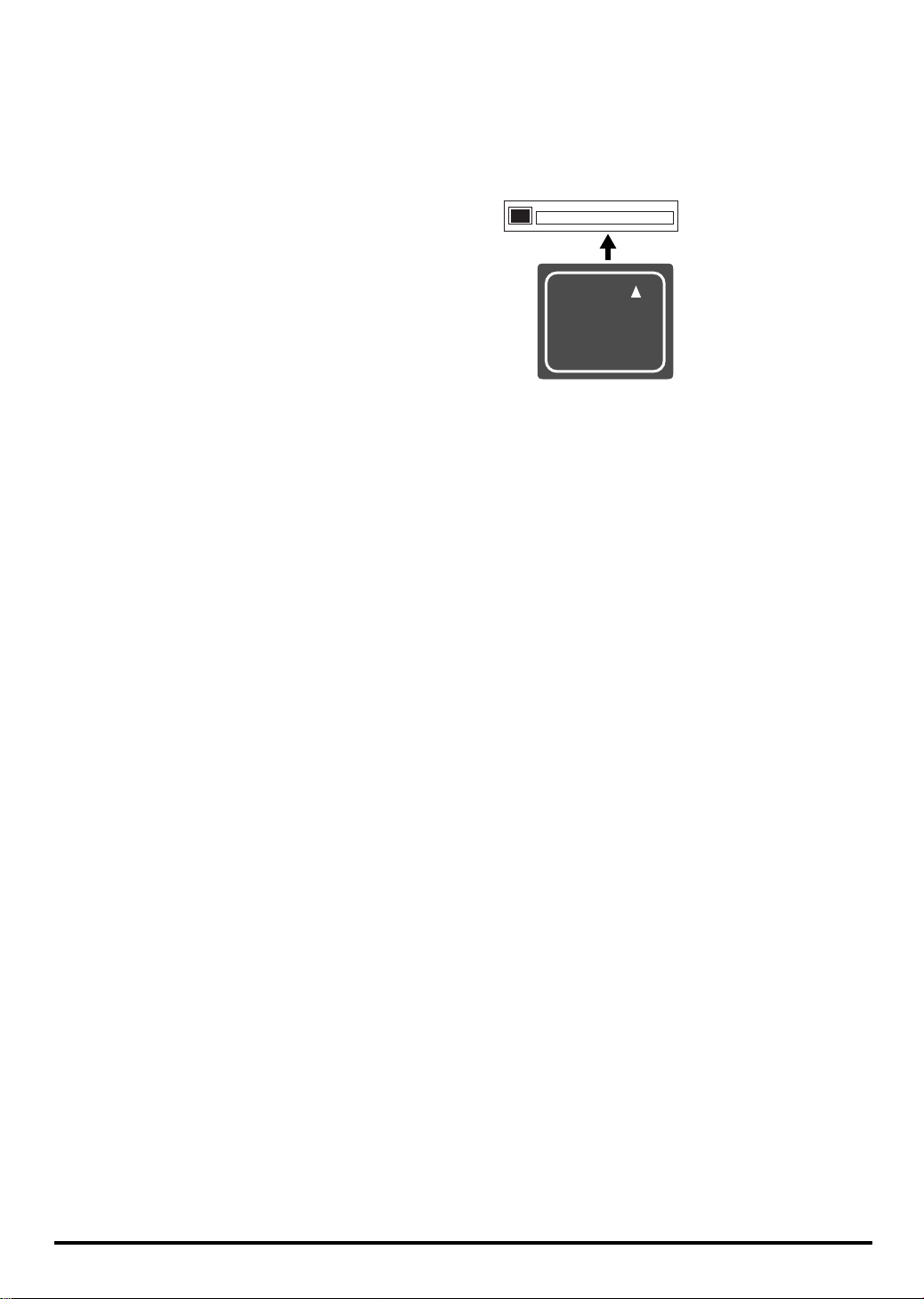
Inserting a Memory Card
1.
Insert the memory card into the card slot located on the front panel.
You can insert a memory card whether the SP-606 is turned on or off.
Carefully insert the Memory card all the way in-until it is firmly in place.
When using a memory card for the first time, you must format it on the SP-606. (p. 67)
Memory cards formatted by another device will not be recognized by the SP-606.
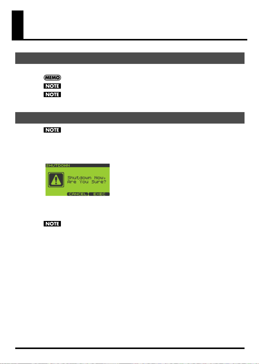
Removing a Memory Card after Shutdown
If the SP-606 is powered up, you must shut it down before removing the memory card. If you
remove the card without shutting down, you risk damaging the internal memory or the contents of
the memory card.
1.
Go to the Play screen (p. 15).
2.
Hold down [FUNC] and press [EXIT] (SHUTDOWN) to get the SHUTDOWN screen.
3.
Press [F3] to shut down.
When you have returned to the Play screen, it is safe to remove the memory card.
If you decide not to shut down, press [F2] (CANCEL).
After shutdown, a memory card will not be detected even if it is present in the card slot. It will be
detected when you remove the memory card from the slot and re-insert it.
4.
Press the eject button located beside the front panel card slot. A portion of the card will protrude, allowing
you to grasp the card and pull it out.
22
Page 23
Quick Start
Playing Samples from the Pads
How to Play a Sample
Strike a pad, and you’ll hear the sample of that pad.
Switching Pad Banks
1.
Go to the Play screen (p. 15).
2.
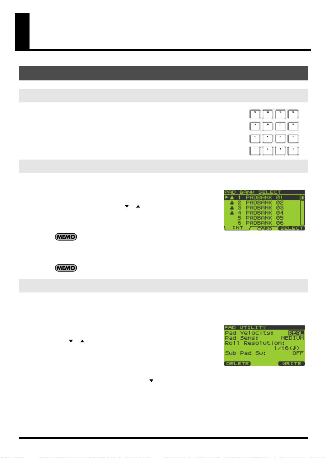
Press [PAD BANK].
The list of pad banks will appear.
3.
Turn the VALUE dial or use [ ][ ][DEC][INC] to move the cursor.
You can select pad banks 1–16 directly by pressing pads [1]–[16].
Pressing [F1] (INT) will move the cursor to the internal memory banks,
and pressing [F2] (CARD) will move to the memory card banks.
Pad banks 9–32 are for the memory card. They cannot be
selected unless a memory card is inserted.
4.
Press [F3] (SELECT) or [ENTER].
The selected pad bank will appear in the display.
When the SP-606 is shipped from the factory, pad banks 1–4 contain preloaded data.
Adjusting the Loudness of the Sound When You Strike the Pads
Here’s how to adjust the loudness of the sounds produced when you strike the pads. This setting is common to all
sixteen pads.
1.
Go to the Play screen (p. 15).
2.
Hold down [FUNC] and press pad [9] (PAD UTIL) to get the PAD
UTILITY screen.
3.
Use [ ][ ] to move the cursor to the “Pad Velocity” line.
4.
Turn the VALUE dial or use [DEC][INC] to select REAL or 1–127.
REAL
: The force with which you strike the pad will determine the
loudness.
1–127
: The loudness will be fixed at the level you specify (127 steps).
5.
If you specified REAL in step 4, press [ ] to move the cursor to the “Pad Sens” line.
If you specified a value of 1–127 in step 4, proceed to step 7.
6.
Turn the VALUE dial or use [DEC][INC] to select either LIGHT, MEDIUM, or HEAVY.
LIGHT
: Sound will be produced even if you strike a pad lightly.
MEDIUM
HEAVY
7.
Press [EXIT] to return to the Play screen.
: This is the standard sensitivity setting.
: You will need to strike a pad strongly in order to produce sound.
23
Page 24
Quick Start
Playing Patterns
Basic Procedure for Playing a Pattern
1.
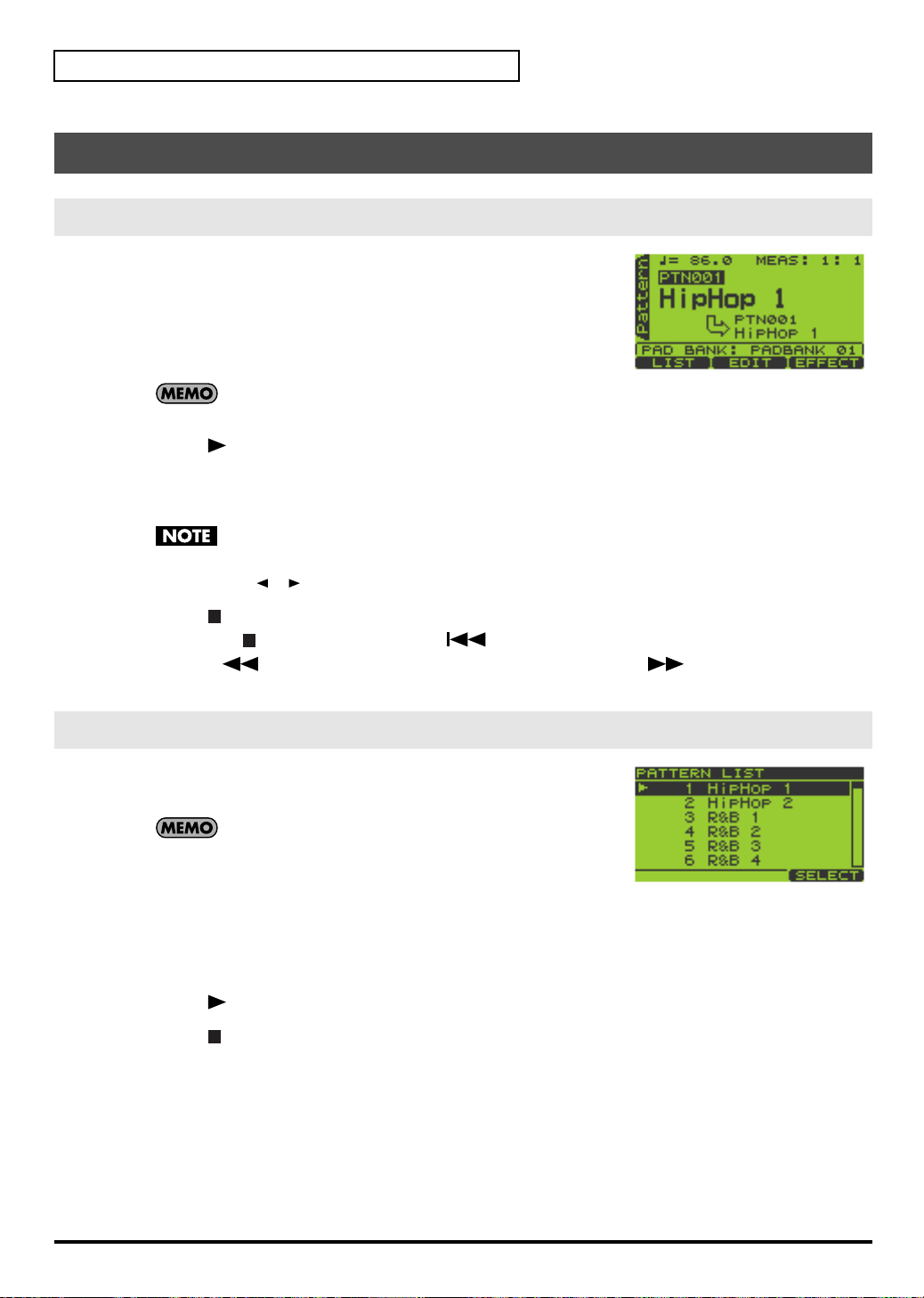
Go to the Pattern Play screen (p. 15).
The upper line of the screen shows the BPM (tempo) and number of
measures in the pattern.
The lower line of the screen shows the number of the currently selected
pad bank.
2.
Turn the VALUE dial or use [DEC][INC] to select a pattern.
When the SP-606 is shipped from the factory, patterns 1–40
contain preloaded pattern data.
3.
Press [ ] (Play) to begin playback.
If you turn the VALUE dial or use [DEC][INC] to select another pattern while a pattern is playing, the name of
that pattern will appear in the lower line, and will be reserved as the next-played pattern. When the currently
playing pattern has played to the end, the reserved pattern will automatically begin playing.
If the pattern number indication shown in the lower line is not highlighted, the SP-606 is already
preparing to switch to the next pattern, so you will not be able to reserve the next pattern.
You can press [ ][ ] while a pattern is playing to force the currently playing pattern to switch.
4.
Press [ ] (Stop) to stop playback.
If you press [ ] (Stop) once again or press [ ] (Top), you will return to the beginning of the pattern.
Pressing [ ] (Backward) moves you one measure back, while pressing [ ] (Forward) moves you one
measure forward.
Selecting and Playing a Pattern from the Pattern List
1.
Go to the Pattern Play screen (p. 15).
2.
Press [F1] (LIST) to get the PATTERN LIST screen.
If the preloaded patterns are protected (p. 58), a lock symbol
is shown at the left of the corresponding pattern in the
screen.
3.
Turn the VALUE dial or use [DEC][INC] to select a pattern, and press [F3] (SELECT) or [ENTER] to confirm
your choice.
Patterns 1–16 can be selected directly by pressing pads [1]–[16].
If you decide you don’t want to select a pattern, you can press [EXIT] to cancel this procedure.
4.
Press [ ] (Play) to start playback.
5.
Press [ ] (Stop) to stop playback.
24
Page 25
Changing the BPM (Tempo) During Pattern Playback
1.
Go to the Pattern Play screen (p. 15).
2.
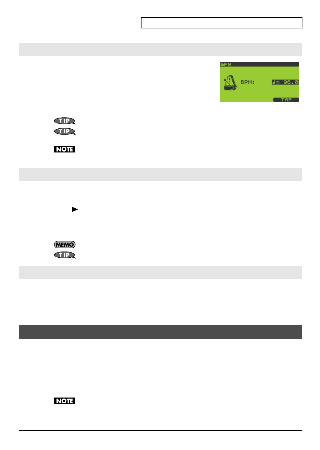
Press [BPM] to get the BPM screen.
The current BPM is displayed.
3.
Turn the VALUE dial or use [DEC][INC] to adjust the BPM (40.0–
200.0).
The BPM can be adjusted in steps of one. You can make adjustments even
while the pattern is playing.
To adjust the BPM in 0.1 units, hold down [FUNC] and turn the VALUE dial.
You can press the [F3] (TAP) button three times or more in succession to set the BPM to the interval
at which you pressed the button (Tap Tempo function).
You cannot change the BPM if “Sync Mode” (p. 79) is set to SLAVE.
4.
Press [EXIT] to return to the Play screen.
Muting Individual Tracks
You can mute (silence) specific tracks while a pattern plays.
1.
Go to the Pattern Play screen (p. 15).
Quick Start
2.
Press [ ] (Play) to play the pattern.
3.
Press TRACK [1]–[4].
Button lit: playing
Button blinking: muted
If a track button is unlit, that track contains no data.
The mute status of each track can be stored with the pattern. (p. 59)
The Number of Samples That Can Be Played Simultaneously
Including the playback of the song/pattern and the sounds you play from the pads, a maximum of eight notes
can be played simultaneously. Each stereo sample uses two notes.
If you attempt to play more than eight notes simultaneously, the samples you most recently played from the pads
will take priority, and the sample played by a previously pressed pad will stop sounding. Samples whose “Play
Type” (p. 50) is set to PHRASE will take priority over SINGLE samples.
Playing an Audio Input Signal
The SP-606’s [INPUT SOURCE] pad lets you start/stop the sound of an external audio input source in the same
way as when controlling a sample. You can also apply effects to this sound.
In the explanation below, we will use a connected CD player as an example.
1.
Make sure that the SP-606 and your CD player are powered off.
2.
On the top panel, turn the AUDIO IN REC LEVEL knob to the minimum position (far left).
3.
Connect your CD player to the rear panel INPUT L/R or DIGITAL IN jack (p. 20).
To prevent malfunction and/or damage to speakers or other devices, always turn down the volume,
and turn off the power on all devices before making any connections.
4.
Power up your CD player.
25
Page 26
Quick Start
5.
Power up the SP-606 using the procedure described in “Turning the Power On” (p. 21).
Wait until the Pattern Play screen (p. 15) appears in the display.
6.
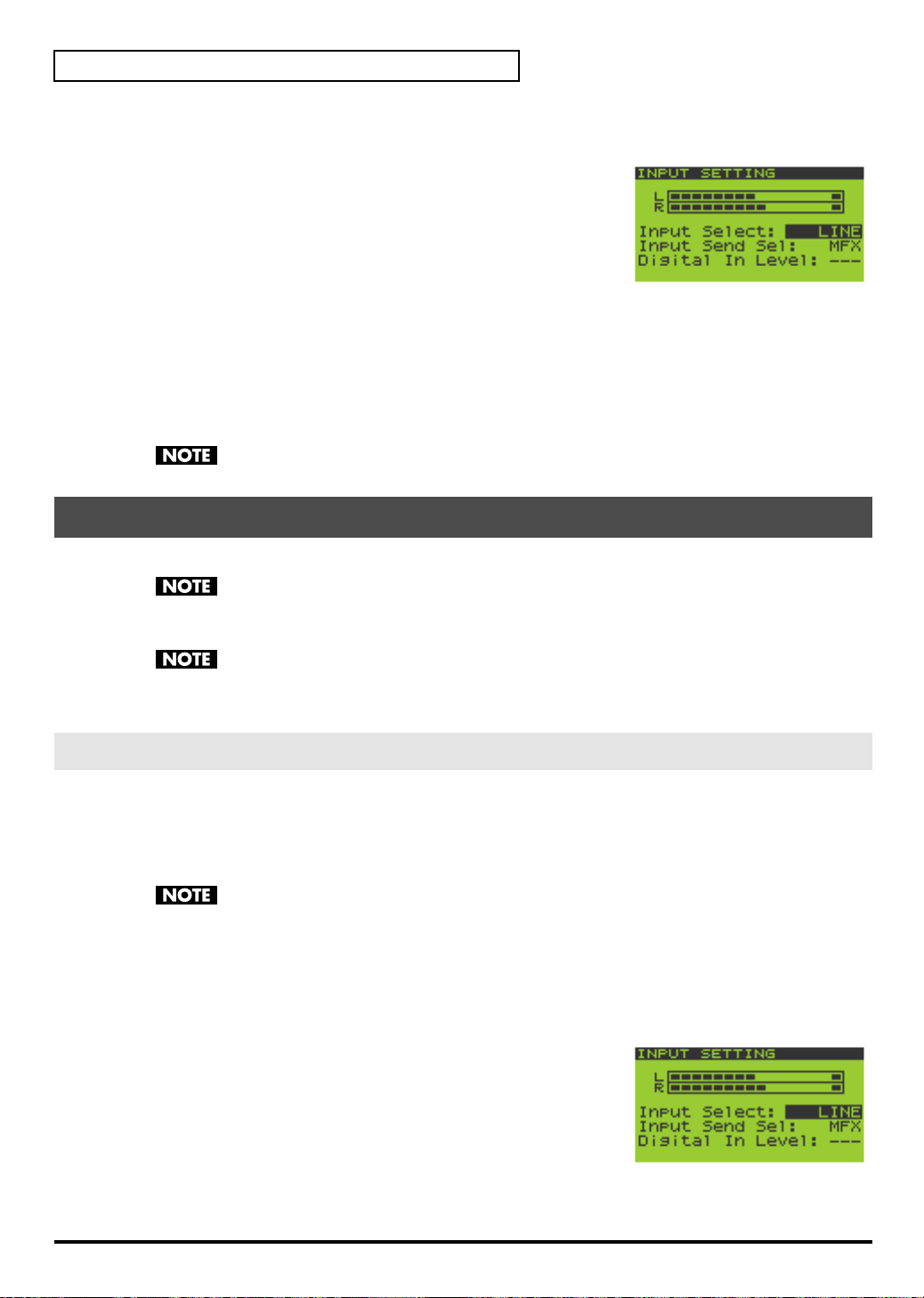
Hold down [FUNC] and press the [INPUT SOURCE] pad to get the
INPUT SETTING screen.
7.
Turn the VALUE dial or use [DEC][INC] to set “Input Select” as
follows.
If you made connections to
If you made connections to
8.
Play back your CD player.
9.
When you press the [INPUT SOURCE] pad so it’s lighted, the external input sound will be heard.
When you press the [INPUT SOURCE] pad once again and switch off its illumination, the sound will stop.
10.
Use the AUDIO IN REC LEVEL knob to adjust the volume.
Adjust the AUDIO IN REC LEVEL knob until the level is as high as you can get it without causing the knob’s
level indicator to light.
If you made connections to DIGITAL IN in step 3, the AUDIO IN REC LEVEL knob has no effect.
INPUT L/R
DIGITAL IN
in step 3:
in step 3:
LINE
DIGITAL
Recording Your Own Samples
The SP-606 lets you sample up to approximately eleven minutes of sound (monaural).
Copyright law prohibits you from recording (sampling) copyrighted audio material belonging to a
third party without permission for any purpose other than personal enjoyment. Do not use this
device to make illegal recordings.
Roland Corporation accepts no responsibility for any damages or penalties you may be required to
pay as a result of making illegal recordings using Roland-manufactured equipment.
As an example, here’s how to sample sound from a CD player.
Preparations for Sampling
Connect your CD player to the SP-606
1.
Make sure that the SP-606 and your CD player are powered off.
2.
On the top panel, turn the AUDIO IN REC LEVEL knob to the minimum (far left).
3.
Connect your CD player to the rear panel INPUT L/R or DIGITAL IN jack (p. 20).
To prevent malfunction and/or damage to speakers or other devices, always turn down the volume,
and turn off the power on all devices before making any connections.
4.
Power up your CD player.
5.
Power up the SP-606 using the procedure described in “Turning the Power On” (p. 21).
Wait until the Pattern Play screen (p. 15) appears in the display.
Specify the input jack, and adjust the input level
6.
Hold down [FUNC] and press [INPUT SOURCE] to get the INPUT
SETTING screen.
7.
Turn the VALUE dial or use [DEC][INC] to set “Input Select” as
follows.
If you made connections to
If you made connections to
26
INPUT L/R
DIGITAL IN
in step 3:
in step 3:
LINE
DIGITAL
Page 27

8.
Play back your CD player and adjust the input level.
If you selected INPUT in step 3, adjust the AUDIO IN REC LEVEL knob until the level is as high as you can get it
without causing the knob’s level indicator to light.
Sampling
1.
Press [SAMPLING] to get the SAMPLING MENU screen.
2.
Press [F1] (SAMPL).
[SAMPLING] will blink, and the
appear.
3.
The display will indicate “Select Pad”; turn the VALUE dial or use
[DEC][INC] to switch the pad bank. For this example, select pad
bank 8. Then press the desired pad to select it as the sampling
destination. For this example, press pad [1].
At this time, pads that do not contain samples will blink.
The pad number is displayed at the left of the upper line in the screen
(PAD 8-1).
Quick Start
If you made connections to DIGITAL IN, the AUDIO IN REC LEVEL knob has no effect.
SAMPLING STANDBY
If the selected pad already contains a sample, you’ll be presented with this message: “A Sample
Already Exists! Overwrite?” If you are sure you want to overwrite the existing sample, press [F3]
(EXEC). To cancel, press [F2] (CANCEL).
If the Pad Bank Protect setting is turned on for a bank, a lock symbol is displayed at the right of the
pad bank number shown in the upper left of the screen. If you press a pad of such a bank, the screen
will indicate “Protected Pad Bank!”, and the pad cannot be selected. If you want to sample into a
pad of this bank, you will have to turn off the Protect setting (p. 31).
screen will
4.
Use [ ][ ] to move the cursor to the “Auto Trig” line.
5.
Turn the VALUE dial or use [DEC][INC] to select the OFF setting.
If you decide to cancel the sampling operation at this point, press [EXIT].
6.
Press the [INPUT SOURCE] pad to hear the audio input signal.
7.
At the appropriate moment in the music, press [SAMPLING] or [F3] (START) to start sampling.
[SAMPLING] will change from blinking to lit.
8.
At the moment you want to stop sampling, press [SAMPLING] or [F3] (STOP).
If you exceed the available sampling time, sampling will stop automatically.
9.
Press the pad to play back the sampled sound.
You can use the BPM Sync function (p. 52) to change the BPM (tempo) of the sampled sound.
If the beginning or end of the sample contains unwanted sound or silence, you can make settings so
that only the desired portion of the sound is actually played. For details, refer to “Specifying the
Start/End Points for Playback (Skipping Unwanted Portions)” (p. 51).
If you are not satisfied with the sampled sound, refer to “Deleting a Sample” (p. 32).
27
Page 28
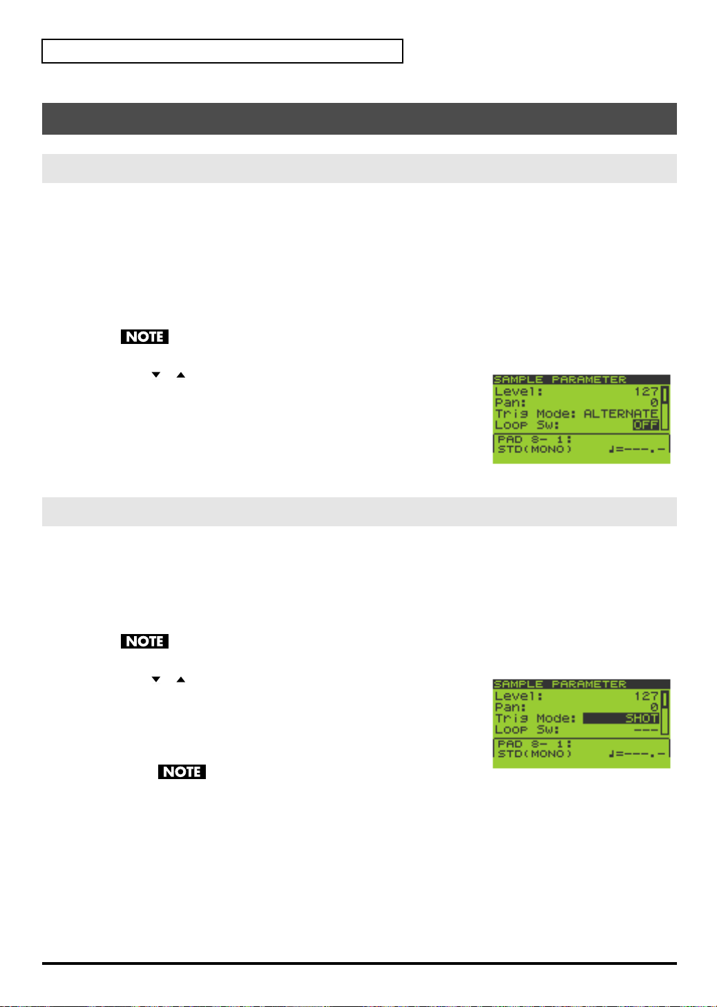
Quick Start
Editing a Sample
Looping a Sample
Causing a sample to play repeatedly from its beginning to its end is called “looping.” The SP-606 makes it easy for
you create phrases by playing phrases repeatedly in this way.
1.
Go to the Play screen (p. 15).
2.
Hold down [FUNC] and press pad [13] (SAMPLE PARAM) to get the SAMPLE EDIT screen.
3.
Press the pad whose sample you want to edit.
If you want to edit a sample that’s in a different pad bank, switch the pad bank (p. 23) and then choose a sample
to edit.
If the pad bank is protected, a lock symbol is displayed in the upper right of the screen. In this case
you will not be able to edit the sample unless you turn off the Protect setting (p. 31).
4.
Use [ ][ ] to move the cursor to the “Loop Sw” line.
5.
Turn the VALUE dial or use [DEC][INC] to select OFF or ON.
OFF
: not looped
ON
: looped
If you want to make settings for other samples as well, repeat steps 3–5.
6.
Press [EXIT] to return to the Play screen.
Changing How the Sample Plays and Stops
1.
Go to the Play screen (p. 15).
2.
Hold down [FUNC] and press pad [13] (SAMPLE PARAM) to get the SAMPLE EDIT screen.
3.
Press the pad whose sample you want to edit.
If you want to edit a sample that’s in a different pad bank, switch the pad bank (p. 23) and then choose a sample
to edit.
If the pad bank is protected, a lock symbol is displayed in the upper right of the screen. In this case
you will not be able to edit the sample unless you turn off the Protect setting (p. 31).
4.
Use [ ][ ] to move the cursor to the “Trig Mode” line.
5.
Turn the VALUE dial or use [DEC][INC] to select either SHOT,
ALTERNATE, or GATE.
SHOT
: The sample will begin playing when you press the pad, and will
stop automatically when the end of the sample is reached.
If you select the SHOT setting, the Loop setting (p. 28)
is ignored; the sample will play only once. Note that if you select SHOT, you will not be able
to interrupt the sound, so use this setting with caution if the sample is extremely long.
ALTERNATE
GATE
: The sample will begin playing when you press the pad, and will continue playing even after you
release the pad. It will stop when you press the pad once again.
: The sample will begin playing when you press the pad, and will stop playing when you release the pad.
28
If you want to make settings for other samples as well, repeat steps 3–5.
6.
Press [EXIT] to return to the Play screen.
Page 29
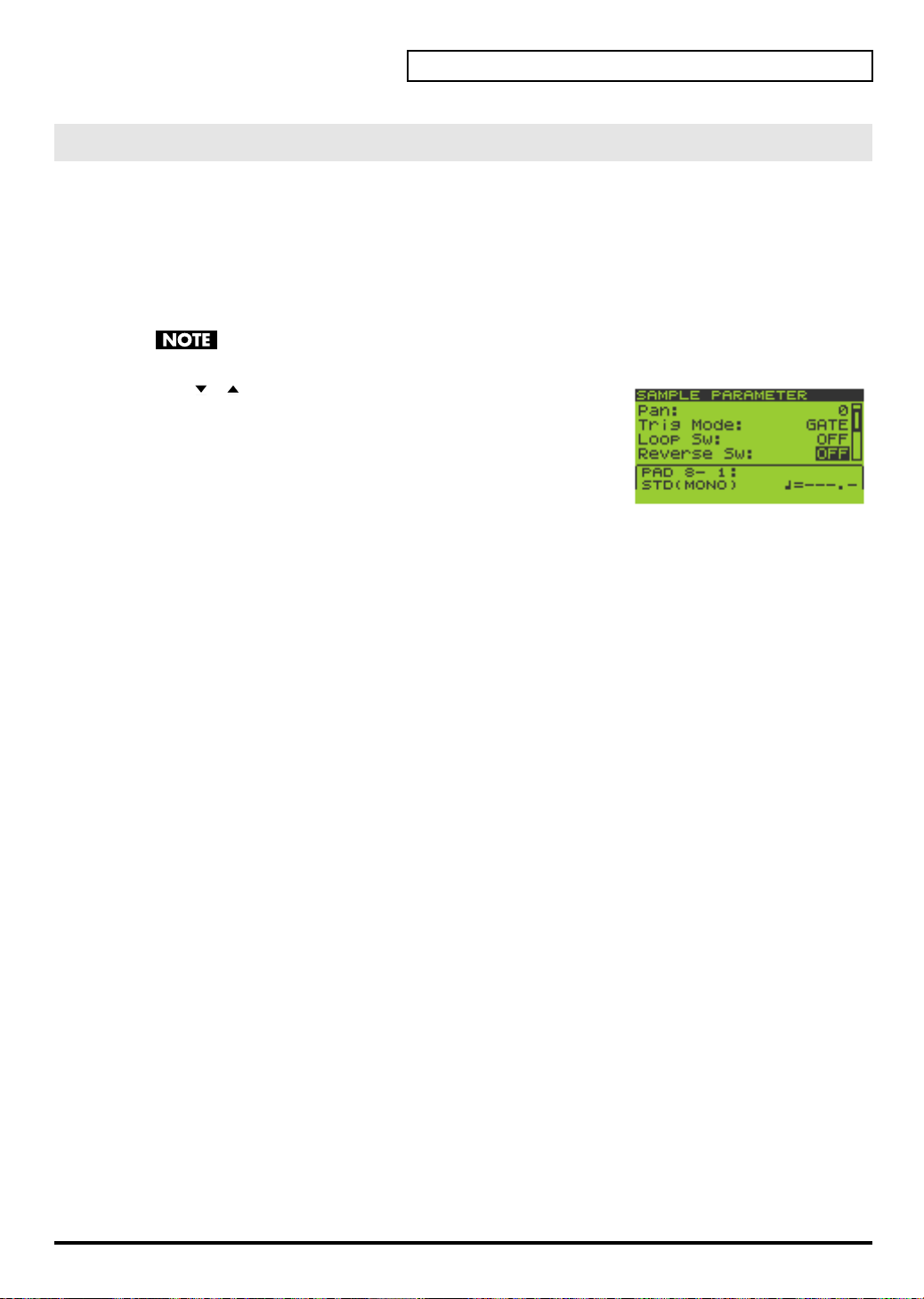
Reversing the Playback
The Reverse setting makes a sample play in the opposite direction, as if a tape were being played backward.
1.
Go to the Play screen (p. 15).
2.
Hold down [FUNC] and press pad [13] (SAMPLE PARAM) to get the SAMPLE EDIT screen.
3.
Press the pad whose sample you want to edit.
If you want to edit a sample that’s in a different pad bank, switch the pad bank (p. 23) and then choose a sample
to edit.
If the pad bank is protected, a lock symbol is displayed in the upper right of the screen. In this case
you will not be able to edit the sample unless you turn off the Protect setting (p. 31).
4.
Use [ ][ ] to move the cursor to the “Reverse Sw” line.
5.
Turn the VALUE dial or use [DEC][INC] to select OFF or ON.
OFF
: not reversed
ON
: reversed
If you want to make settings for other samples as well, repeat steps 3–5.
6.
Press [EXIT] to return to the Play screen.
Quick Start
29
Page 30
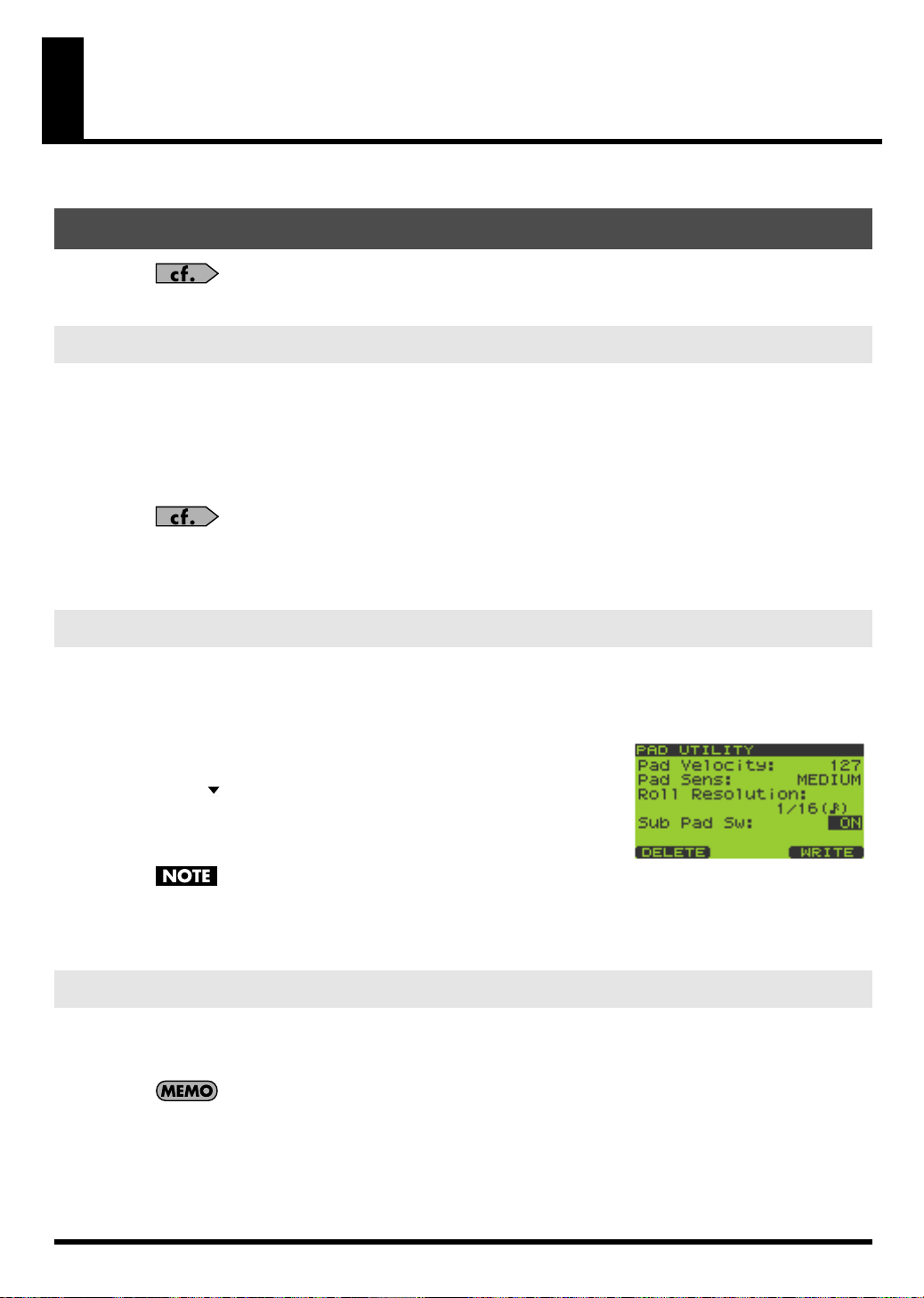
Chapter 1. Playing the Pads/Making Pad Settings
Playing the Pads
For details on basic ways to play the pads, refer to “Playing Samples from the Pads” in the Quick
Start (p. 23).
Playing a Roll
Here’s how you can make a sample play repeatedly (i.e., “roll”) as long as you hold down a pad.
1.
Go to the Play screen (p. 15).
2.
Press [ROLL] so the button is lit; this enables the Roll function.
3.
Hold down a pad, and the roll will begin.
You can play a roll by pressing any pad [1]–[16], or by pressing multiple pads simultaneously.
You can specify the resolution of the roll. Refer to “Basic Procedure for Pad Utility Settings” (p. 31)
and “Pad Utility Parameters” (p. 31).
4.
When you release the pad, the roll will stop.
5.
To turn off the Roll function, press [ROLL] so its illumination is turned off.
Using the Sub Pad Function
You can use the Sub Pad to play the sample of the pad you struck most recently. This is a convenient way to play
a drum roll manually.
1.
Go to the Play screen (p. 15).
2.
Hold down [FUNC] and press pad [9] (PAD UTIL) to get the PAD
UTILITY screen.
3.
Press [ ] to move the cursor to the “Sub Pad Sw” line.
4.
Turn the VALUE dial or use [DEC][INC] to turn the setting ON.
Pad [16] will light green, and will now operate as the Sub Pad.
This does not erase the sample of pad [16]; its original
sample will reappear when you turn off the Sub Pad setting.
5.
When you press pad [16], the sample of the most recently struck pad will sound.
6.
If you turn the “Sub Pad Sw” OFF, pad [16] will go dark, and the Sub Pad function will be disabled.
Using the Hold Function
The Hold function makes a sample continue sounding even after you take your finger off the pad. This is
convenient when you want a phrase loop sample to continue playing.
However, you cannot exceed the maximum polyphony of eight notes even when using the Hold function.
Hold applies only to samples for which GATE playback (p. 50) is specified. Hold does not apply to
samples for which ALTERNATE playback or SHOT playback (p. 50) is specified, nor to the Roll
function (p. 30).
30
1.
Go to the Play screen (p. 15).
2.
Press a pad to play its sample.
Page 31

3.
Before you take your finger off the pad, press the [HOLD] pad while the sample is still sounding.
The Hold function will be turned on, and the sample will continue sounding even after you take your finger off
the pad.
4.
The sound will stop when you press the currently sounding pad or the [HOLD] pad once again.
When you press the [HOLD] pad again, all currently held sounds will stop.
Making Pad Settings
Pad Bank Protect
You can protect a pad bank so that it cannot be edited or erased.
When the SP-606 is shipped from the factory, you will not be able to edit or erase pad banks 1–4
since they are protected to prevent the samples from being deleted accidentally.
1.
Go to the Play screen (p. 15).
2.
Hold down [FUNC] and press [PAD BANK] to get the PAD BANK
PROTECT screen.
A list of the pad banks will appear.
3.
Turn the VALUE dial or use [ ][ ][DEC][INC] to move the cursor.
4.
Press [F1] (PRTCT) to turn on the Protect setting. A lock icon will
appear at the left edge of the cursor line.
To turn off Protect, press [F1] (PRTCT) once again. The lock icon will
disappear.
5.
Press [EXIT] to return to the Play screen.
Chapter 1. Playing the Pads/Making Pad Settings
Basic Procedure for Pad Utility Settings
1.
Go to the Play screen (p. 15).
2.
Hold down [FUNC] and press pad [9] (PAD UTIL) to get the PAD
UTILITY screen.
3.
Use [ ][ ] to select the setting (parameter) you want to edit.
4.
Turn the VALUE dial or use [DEC][INC] to edit the parameter value.
5.
Press [EXIT] to return to the Play screen.
Pad Utility Parameters
Parameter
Pad Velocity
Pad Sens LIGHT,
Roll Resolution 1/4–1/48 Specifies the resolution (interval) for the Roll function (p. 30).
Sub Pad Sw OFF, ON Specifies the Sub Pad setting (p. 30).
Value Explanation
REAL,
1–127
MEDIUM,
HEAVY
Specifies the loudness of the sound when you strike a pad.
REAL
: You can vary the loudness at which the sample plays by varying the force
of your pad strikes.
1–127
: The sample will play at the velocity value you specify.
Adjusts the sensitivity of the pad. This specifies how the loudness will respond to
the force of your strike.
LIGHT
: Even light strikes will produce loud sounds.
MEDIUM
HEAVY
: There will be no sound unless you strike the pad strongly.
*
This setting is used only if “Pad Velocity” is set to REAL.
: Medium sensitivity.
31
Page 32

Chapter 1. Playing the Pads/Making Pad Settings
Deleting a Sample
1.
Go to the Play screen (p. 15).
2.
Hold down [FUNC] and press pad [9] (PAD UTIL) to get the PAD UTILITY screen.
3.
Press [F1] (DELETE) to get the PAD DELETE screen.
4.
Press the pad whose sample you want to delete; the pad number will
be highlighted (black).
To cancel your selection, press a selected pad once again; the indication
will revert to white.
You can select more than one pad simultaneously.
If you want to select samples from another pad bank, turn the VALUE
dial or use [DEC][INC] to switch the pad bank, and press a pad to select a sample.
Pads that don’t contain a sample are displayed as a dotted line, and cannot be selected.
5.
To delete the sample(s), press [F3] (EXEC).
If you decide to cancel, press [F2] (CANCEL) or [EXIT].
Never turn off the power while the display indicates “Now Processing...”
6.
Press [EXIT] to return to the Play screen.
Using the Clipboard to Copy a Sample
The Clipboard function lets you temporarily save a desired sample, which you can then copy to another location.
You can also copy samples between pad banks.
1.
Go to the Play screen (p. 15).
2.
Hold down the pad whose sample you want to copy, and press [CLIPBOARD].
The sample will be copied to the clipboard, and [CLIPBOARD] will light.
The copied sample will sound when you press [CLIPBOARD].
If you delete the copy-source sample at this time, the sample copied to the clipboard will also be
deleted.
3.
Hold down [CLIPBOARD] and press the copy-destination pad.
When you press [CLIPBOARD], pads that contain samples will light.
If you want to copy the sample to a different pad bank, press [PAD BANK] and select the desired pad bank (p.
23).
To delete the copied sample from the clipboard, hold down [FUNC] and press [CLIPBOARD].
You cannot copy to a pad that already contains a sample.
32
Page 33

Chapter 2. Using Effects
The SP-606 contains three built-in effect modules, which can be used simultaneously.
“MFX” stands for Multi-Effects.
Refer to “Audio Signal Flow Inside the SP-606” (p. 12).
Basic Effect Operation
Turning Effects On/Off
1.
Go to the Play screen (p. 15).
2.
Press [MFX1], [MFX2], or [MASTERING] to turn each effect on/off.
Lit: ON
Unlit: OFF
When you turn [MFX1] or [MFX2] on, the MFX module that you turned on will automatically
become the module controlled by the CTRL 1–3 knobs.
Using the Control Knobs
Switching the MFX Module Controlled by the Control Knobs
Here’s how to select whether the control knobs will control MFX1 or MFX2.
1.
Go to the Play screen (p. 15).
2.
Hold down [KNOB ASSIGN] to see which MFX module the knobs are controlling.
Of the [MFX1] and [MFX2] buttons, the MFX button that blinks indicates the MFX module currently controlled by
the knobs.
3.
Continue to hold down [KNOB ASSIGN], and press the button that is not blinking; this switches the MFX
module that is controlled by the knobs.
Controlling the Effect
1.
Go to the Play screen (p. 15).
2.
Turn the CTRL 1–3 knobs to adjust the MFX.
3.
If you want to check the currently used type of effect and its settings, press [F3] (EFFECT) to get the
EFFECT INFO (Effect Information) screen.
4.
Press [EXIT] to return to the Play screen.
Choosing the MFX Type from a List
1.
Go to the Play screen (p. 15).
2.
Press [F3] (EFFECT) to get the EFFECT INFO (Effect Information)
screen.
The screen will show the MFX settings controlled by the CTRL 1–3 knobs.
You can get the same screen by holding down [FUNC] and
pressing [MFX1] or [MFX2].
3.
Press [F2] (MFX1/2) to switch between MFX1 and MFX2.
The upper right of the screen indicates whether MFX1 or MFX2 settings are shown.
The MFX unit being controlled by the CTRL 1–3 knobs will automatically switch to the MFX unit that is shown in
the display.
33
Page 34

Chapter 2. Using Effects
You can exchange MFX1 and MFX2 by holding down [FUNC] and pressing [F1] (EXCHG). A
message of “Exchange MFX1&2, Are You Sure?” will appear. Press [F3] (EXEC) to perform the
exchange, or press [F2] (CANCEL) if you decide to cancel the operation.
4.
Press [F1] (LIST) to get the MFX1 TYPE LIST or MFX2 TYPE LIST
screen.
5.
Turn the VALUE dial or use [ ][ ][DEC][INC] to select the effect
type.
Effect types 1–16 can be selected directly by pressing pads
[1]–[16].
6.
Press [F3] (SELECT) or [ENTER] to confirm your choice.
You will return to the
If you decide to cancel, press [EXIT].
EFFECT INFO
(Effect Information) screen.
Selecting What the Effect Will Apply to (MFX Assign)
You can select whether effects will be applied to multiple pads, to individual pads, or to the audio input via USB.
1.
Go to the Play screen (p. 15).
2.
Hold down [FUNC] and press pad [12] (MFX ASGN) to get the MFX
ASSIGN screen.
3.
Turn the VALUE dial or use [DEC][INC] to select the pad bank for
which you want to make settings.
4.
Press the appropriate pads to turn MFX assign on/off. The setting
will alternate on/off each time you press the pad.
MFX is turned on for
pads
that are displayed in black on the screen.
You can press [F2] (BANK) to switch all sixteen pads of the pad bank on/off.
5.
Pressing [F1] (USB) will switch MFX assign on/off for the audio input received via USB.
MFX is enabled for
6.
Press [F3] (WRITE) to save the settings.
A message of “MFX Assign Write, Are You Sure?” will appear. Press [F3] (EXEC) to save the settings, or press [F2]
(CANCEL) if you decide to cancel the operation.
7.
Press [EXIT] to return to the Play screen.
USB
audio if the
Making Mastering Settings
1.
Go to the Play screen (p. 15).
2.
Press [F3] (EFFECT) to get the EFFECT INFO (Effect Information)
screen.
The screen shows the settings for the MFX module being controlled by
the CTRL 1–3 knobs.
3.
Press [F3] (MASTER) to get the MASTERING screen.
You can also get this screen by holding down [FUNC] and
pressing [MASTERING].
Selecting a Mastering Setup
4.
Press [F1] (LIST) to get the MASTERING SETUP LIST screen.
5.
Turn the VALUE dial or use [ ][ ][DEC][INC] to select the mastering setup you want to use.
“1 USER SET” is selected when you turn on the power. If you want to use a certain preset setting as
the power-on default, write those preset settings to “1 USER SET.”
USB
indication in the screen is highlighted in black.
34
Page 35

6.
Press [F3] (SELECT) or [ENTER] to confirm your choice.
You will return to the
MASTERING
screen.
If you decide to cancel, press [EXIT].
Editing the Mastering Setup
7.
Use [ ][ ] to select the parameter you want to edit.
Turn the VALUE dial or use [DEC][INC] to edit the parameter value.
Parameter Value Explanation
Spilt Freq 200–8000Hz Frequency at which the High and Low ranges are divided
In Level -24–0dB Mastering input volume
Low Attack 0.05–50ms Time over which compression is applied to the volume after the input exceeds the
Low Release 0.05–2000ms Time over which compression is released after the input falls below the Low
Low Threshold 0–127 Volume level at which compression begins to be applied to the low frequency
Low Ratio 1:1–inf:1 Compression ratio for the low frequency range (inf: infinite)
Low Level -24–+24dB Output volume of the low frequency compressor
High Attack 0.05–50ms Time over which compression is applied to the volume after the input exceeds the
High Release 0.05–2000ms Time over which compression is released after the input falls below the High
High Threshold 0–127 Volume level at which compression begins to be applied to the high frequency
High Ratio 1:1–inf:1 Compression ratio for the high frequency range (inf: infinite)
High Level -24–+24dB Output volume of the high frequency compressor
Low Threshold
Threshold
range
High Threshold
Threshold
range
Chapter 2. Using Effects
8.
If you want to save your settings, press [F3] (WRITE) to save them to “1 USER SET.”
9.
The display will ask “System Write, Are You Sure?” To save your settings, press [F3] (EXEC) or [ENTER].
If you decide not to save your settings, press [F2] (CANCEL) or [EXIT].
List of Effects
MFX CTRL 1 CTRL 2 CTRL 3
1 FILTER + DRIVE CUTOFF RESO DRIVE
This is a low pass filter with
overdrive. It cuts the high-frequency range and adds distortion.
2 REVERB REV TIME HF DAMP E.LEVEL
This is a reverb that cuts the reverb sound midway through
its decay.
3 DELAY DLY TIME FEEDBACK E.LEVEL
This is a stereo delay Adjusts the delay length (*2) Adjusts the proportion of the
4 TAPE ECHO
This simulates a classic tapetype echo unit.
5 ISOLATOR LOW MIDDLE HIGH
Isolates or eliminates the low,
mid, or high-frequency regions.
Adjusts the frequency at which
the sound will be cut.
Adjusts the length of the reverberation.
Adjusts the amount of peak
(boost) applied to the region of
the cutoff frequency.
Adjusts the frequency at which
the high-frequency portion of
the reverb is cut.
delayed sound that will be returned to the input.
Adds distortion.
Adjusts the volume of the reverb sound.
Adjusts the volume of the delay sound.
REPEAT INTENS E.LEVEL
Adjusts the tape speed. Adjusts the number of echo re-
Isolates/eliminates the lowfrequency range.
peats.
Isolates/eliminates the midfrequency range.
Adjusts the volume of the echo
sound.
Isolates/eliminates the highfrequency range.
35
Page 36

Chapter 2. Using Effects
MFX CTRL 1 CTRL 2 CTRL 3
6 COMPRESSOR SUSTAIN ATTACK LEVEL
Makes the sound levels more
consistent.
7 LO-FI PROCESSOR
Produces a “lo-fi” sound. Adjusts the sampling rate. (*3) Adjusts the bit depth (2–14 BIT,
Adjusts the amount of compression.
Adjusts the sense of attack. Adjusts the volume.
SMPL RATE BIT FILTER
OFF)
Adjusts the filter depth.
8 GUITAR AMP SIM AMP TYPE AMP VOL SPEAKER
Simulates a guitar amp Selects the type of guitar amp.
OFF, JC-120, Clean Twin,
Match Drive, BG Lead,
MS1959 I, MS1959 II,
MS1959 I+II, SLDN Lead,
Metal 5150, Metal Lead,
OD-1, OD-2 Turbo,
Distortion, Fuzz
Adjusts the output volume. Selects the speaker type. (*4)
9 OVERDRIVE DRIVE TONE LEVEL
Mildly distorts the sound. Adjusts the amount of distor-
tion.
Adjusts the tone. Adjusts the volume.
10 PITCH SHIFTER PITCH FEEDBACK BALANCE
Changes the pitch. Changes the pitch over a +/-2
octave range.
Adjusts the amount of feedback for the pitch-shifted
sound.
Adjusts the balance between
the effect sound and the direct
sound.
11 FEEDBACK RIPPER
This effect periodically cuts the
sound and sends the cut portion to a delay. You can create
new phrases by applying this
effect to a phrase (e.g., drum
phrase).
RATE DLY TIME FEEDBACK
Adjusts the interval (*2) at
which the effect is applied.
Adjusts the delay time (*2)
from when the original sound
is heard until the delay sound
is heard.
Adjusts the proportion of delayed sound that is returned to
the input.
12 REVERSE THRESHOLD TIME BALANCE
Adds a reversed copy to the
original sound.
Adjusts the volume level at
which the reverse begins.
Adjusts the delay time (*2)
from when the original sound
is heard until the reverse sound
is heard.
Adjusts the volume balance between the direct sound (D) and
effect sound (E).
13 TUMBLING TIME PAN BALANCE
Adds a “rotating” delay sound.
Particularly effective when applied to drum sounds.
14 FLANGER
Produces a twisting modulation effect reminiscent of a jet
aircraft taking off and landing.
15 STEP FLANGER
Varies the pitch of the flanger
sound in stepwise fashion. The
interval of the pitch change can
also be specified as a note value
relative to the specified tempo.
Adjusts Time “A” in the diagram.
Level
original tone
A
Adjusts the left/right panning. Adjusts the volume balance be-
tween the direct sound (D) and
effect sound (E).
Time
DEPTH RATE RESO
Adjusts the depth of modulation.
Adjusts the speed of modulation.
Adjusts the character of the
modulation.
RATE STEP RATE RESO
Adjusts the rate of modulation. Adjusts the rate (*2) of pitch
change.
Adjusts the character of the
modulation.
36
Page 37

Chapter 2. Using Effects
MFX CTRL 1 CTRL 2 CTRL 3
16 BPM AUTO PAN DEPTH RATE WAVE
Cyclically varies the pan position of the sound in synchronization with the BPM (tempo).
Adjusts the depth of the effect. Adjusts the rate (*2) at which
the effect is applied.
Specifies how the panning will
change.
TRI
: Triangle wave
SQU
: Square wave
SIN
: Sine wave
SAW1
: Sawtooth wave (as-
cending)
SAW2
:
ing)
17 AUTO PAN DEPTH RATE WAVE
Cyclically varies the pan position of the sound.
Adjusts the depth of the effect. Adjusts the rate at which the ef-
fect is applied.
Specifies how the panning will
change.
TRI
: Triangle wave
SQU
: Square wave
SIN
: Sine wave
SAW1
: Sawtooth wave (as-
cending)
SAW2
:
ing)
18 BPM TREMOLO DEPTH RATE WAVE
Cyclically varies the volume in
synchronization with the BPM
(tempo).
Adjusts the depth of the effect. Adjusts the rate at which the ef-
fect is applied.
Specifies how the volume will
change.
TRI
: Triangle wave
SQU
: Square wave
SIN
: Sine wave
SAW1
: Sawtooth wave (as-
cending)
SAW2
:
ing)
19 TREMOLO DEPTH RATE WAVE
Cyclically varies the volume. Adjusts the depth of the effect. Adjusts the rate at which the ef-
20 BPM SLICE+FLANG
Periodically cuts the sound in
synchronization with the BPM
(tempo). A flanger is also applied.
21 SLICER + FLANGER
Periodically cuts the sound. A
flanger is also applied.
PTN RATE FLANGER
Specifies the timing at which
the sound is cut. (
*5
)
PTN RATE FLANGER
Specifies the timing at which
the sound is cut. (
*5
)
fect is applied.
Adjusts the length of the PTN
*2
).
(
Adjusts the length of the PTN. Adjusts the depth of the
Specifies how the volume will
change.
TRI
: Triangle wave
SQU
: Square wave
SIN
: Sine wave
SAW1
: Sawtooth wave (as-
cending)
SAW2
:
ing)
Adjusts the depth of the
flanger.
flanger.
22 ROTARY HI RATE LOW RATE LEVEL
Simulates the sound of a classic
rotary speaker unit. Since the
operation of the high-frequency and low-frequency rotors
can be specified independently, the distinctive modulation
is simulated realistically.
Adjusts the rate of the high-frequency rotor.
Adjusts the rate of the low-frequency rotor.
Adjusts the output volume.
23 CHORUS DEPTH RATE E.LEVEL
Adds spaciousness and depth
to the sound.
Adjusts the depth of modulation.
Adjusts the rate of modulation. Adjusts the volume of the ef-
fect sound.
Sawtooth wave (descend-
Sawtooth wave (descend-
Sawtooth wave (descend-
Sawtooth wave (descend-
37
Page 38

Chapter 2. Using Effects
MFX CTRL 1 CTRL 2 CTRL 3
24 PHASER DEPTH RATE RESO
Adds modulation to the sound. Adjusts the depth of modula-
tion.
Adjusts the speed of modulation.
Adjusts the character of modulation.
25 STEP PHASER RATE STEP RATE RESO
Varies the pitch of the phaser
sound in stepwise fashion.
Adjusts the rate of modulation. Adjusts the rate of pitch change
*2
).
(
Adjusts the character of modulation.
26 RING MODULATOR
Gives the sound a metallic
character.
FREQ E.LEVEL D.LEVEL
Adjusts the pitch of the metallic sound.
Adjusts the volume of the effect sound.
Adjusts the volume of the direct sound.
27 STEREOIZER SHIFT BALANCE LEVEL
Creates a pseudo-stereo effect
by delaying either the left or
right side of the sound. Particularly effective when applied to
a monaural sound.
Adjusts the amount of delay
between left and right. Negative
(-) settings delay the left, and
positive (+) settings delay the
right side. At the center position, there is no delay.
Adjusts the volume balance between the direct sound (D) and
effect sound (E).
Adjusts the output volume.
28 SPACE-D DEPTH RATE BALANCE
A multi-stage chorus that applies two phases of modulation
in stereo. This does not create a
sense of movement, but rather
a clear and transparent chorus
effect.
Adjusts the depth of modulation.
Adjusts the rate of modulation. Adjusts the volume balance be-
tween the direct sound (D) and
the effect sound (E).
29 LOW BOOST BST FREQ BST GAIN LEVEL
Boosts the volume of the lowfrequency range to create a
deeper sound.
Adjusts the frequency (50–125
Hz) at which the low-frequency range will be boosted.
Adjusts the amount of boost
applied to the low-frequency
range.
Adjusts the output volume.
30 EQUALIZER LOW MIDDLE HIGH
Adjusts the volume of each frequency range.
Adjusts the volume of the lowfrequency range.
Adjusts the volume of the midfrequency range.
Adjusts the volume of the highfrequency range.
31 RADIO TUNING TUNING NOISE LV FREQ RNG
Simulates the sound heard
from a radio.
32 VINYL SIMULATOR
Simulates the sound of a vinyl
record.
33 GATE
Uses the volume of the input
source coming into the effect to
cut the release portion of the reverberant sound. Use this
when you want to forcibly
shorten the decay of a sound.
34 NOISE GENERATOR
Produces noise. Adjusts the color (tonal charac-
Adjusts the amount of tuning
inaccuracy.
Adjusts the volume of the
noise.
Adjusts the tonal character.
COMP NOISE LV WOW/F
Adjusts the sense of compression typical of an analog
record.
Adjusts the volume of the noise
typical of an analog record.
Adjusts the rotational instability typical of an analog record.
THRESHOLD MODE RELEASE
Adjusts the volume level at
which the gate begins to close.
Selects the type of gate.
When the volume of the
GATE:
input source falls, the gate will
close, cutting the input source.
When the volume of the
DUCK:
input source rises, the gate will
close, cutting the input source.
Adjusts the time from when
the gate begins to close after
the hold time has elapsed until
it finishes closing.
COLOR QUALITY LEVEL
ter) of the “rushing” or “hissing” noise.
Adjusts how often scratch
noise (as produced by scratches on a record) will appear.
Adjusts the volume of the
“rushing” or “hissing” noise.
35 ENHANCER SENS MIX LEVEL
Controls the overtone structure
of the high-frequency range to
add sparkle to the sound and
improve the definition.
Adjusts the depth of the enhancer effect.
Adjusts the volume of the generated overtones.
Adjusts the output volume.
38
Page 39

Chapter 2. Using Effects
MFX CTRL 1 CTRL 2 CTRL 3
36 DISTORTION DIST TONE LEVEL
Severely distorts the sound. Adjusts the amount of distor-
Adjusts the tone. Adjusts the volume.
tion.
37 FUZZ DRIVE TONE LEVEL
Adds new overtones to the
sound, distorting it severely.
Adjusts the amount of distortion.
Adjusts the tone. Adjusts the volume.
38 WAH SENS FREQ PEAK
Produces a wah effect. Adjusts the sensitivity of the
wah effect.
39 CENTER CANCELER
Cancels sounds that are localized at the center of the sound
field, such as vocals.
L-R BAL LO BOOST HI BOOST
Finds the point at which the
sound is cancelled most effectively.
Adjusts the frequency of the effect sound.
Boosts the low-frequency
sounds localized at the center
of the sound field, such as bass.
Adjusts the peak level of the
wah.
Boosts the high-frequency
range.
40 CHROMATIC P.S. PITCH1 PITCH2 BALANCE
This is a two-voice pitch shifter
that lets you adjust the pitch in
semitone steps.
Adjusts pitch 1 in semitone
steps over a range of +/-1 octave.
Adjusts pitch 2 in semitone
steps over a range of +/-1 octave.
Adjusts the balance between
the effect sound and direct
sound.
41 VOICE TRANSFORMER FORMANT E.LEVEL D.LEVEL
Processes a human voice to create a variety of vocal charac-
Adjusts the vocal formant
(character).
Adjusts the volume of the effect sound.
Adjusts the volume of the direct sound.
ters.
42 OCTAVE -2OCT -1OCT D.LEVEL
Adds lower octaves to the
sound.
Adds the sound two octaves
below.
Adds the sound one octave below.
Adjusts the volume of the direct sound.
43 SUBSONIC THRESHOLD RELEASE BALANCE
Adds a sine wave of approximately 30 Hz according to the
volume of the input source
coming into the effect. By adding a small amount of this to
Adjusts the volume level at
which the sine wave begins to
sound.
Adjusts the time over which
the sine wave disappears when
the input source falls below the
threshold.
Adjusts the volume balance between the direct sound (D) and
effect sound (E).
(for example) a kick drum, you
can create a fatter kick
*1
sound.(
44 OSCILLATOR(PAD)
Uses DSP to simulate a synthesizer oscillator. You can use the
pads to change the pitch of the
oscillator. (
*
45 ENVELOPER(PAD)
Uses DSP to simulate an envelope follower. You can use the
pads to vary the envelope. (
*
)
*1
)
You can create a simple DSP
synthesizer by selecting “OSCILLATOR” for MFX1 and
“ENVELOPER” for MFX2.
*1
You can create a simple DSP
synthesizer by selecting “OSCILLATOR” for MFX1 and
“ENVELOPER” for MFX2.
TUNE OSC WAVE BALANCE
Adjusts the pitch of the oscillator sound.
CUTOFF
Selects the waveform of the oscillator.
TRI
(Triangle wave)
SAW
(Sawtooth wave)
PLS1
PLS2
PLS3
PLS4
PLS5
PLS6
PLS7
PLS8
PLS9
PWM = 0 : PLS1, PLS2, PLS3
PWM = llight : PLS4, PLS5, PLS6
PWM = deep : PLS7, PLS8, PLS9
RESO RELEASE
Adjusts the cutoff frequency. Adjusts the amount of boost
applied at the region of the cut-
)
off frequency.
Adjusts the volume balance between the direct sound (D) and
effect sound (E).
Adjusts the time from when
you press a pad until the maximum volume is reached.
39
Page 40

Chapter 2. Using Effects
*
1:
For effect types 43–45, you can hold down [FUNC] and press [F2] (SUB) to access a sub-parameter screen. The tables shown
below list the parameters that appear in these screens. Press [F3] (EXIT) to return to the previous screen.
43 SUBSONIC
Value Explanation
E.LEVEL 0–127 Adjusts the volume of the effect sound.
PITCH 0–127 Adjusts the frequency of the sine wave.
ATTACK 0–127 Adjusts the time from when the source exceeds the threshold until the sine wave is heard.
44 OSCILLATOR(PAD) Value Explanation
EFFECT LEVEL 0–127 Adjusts the volume of the effect sound.
PAD1 KEY C- –G9 Adjusts the key sounded by the oscillator when you press PAD 1.
LFO RATE 0–127 An LFO is an oscillator used to apply modulation; by increasing the vibrato or PWM you
can modulate the pitch or tone in a variety of ways.
LFO WAVE SAW,
TRI,
SQR,
S-H
(Sawtooth wave)
(Sample & Hold wave)
TRI
(Triangle wave)
SQR
(Square wave)
SAW
S-H
OSC TUNE -24–+24 Specifies the coarse tuning (semitone steps) of the oscillator pitch.
OSC VIB DEPTH 0–127 Adjusts the depth of vibrato (using the LFO to cyclically modulate the pitch) for the oscil-
lator.
OSC XMOD 0–127 Adjusts the depth of cross modulation (using the SUB OSC to modulate the pitch of the
oscillator).
OSC LEVEL 0–127 Adjusts the volume of OSC.
SUB OSC WAVE SAW,
Selects the SUB OSC waveform. (The choices are the same as for OSC WAVE on p. 39)
TRI,
PLS1–9
SUB OSC TUNE -24–+24 Adjusts the coarse tuning (semitone steps) of the SUB OSC pitch.
SUB OSC VIB DEPT 0–127 Adjusts the depth of vibrato (using the LFO to cyclically modulate the pitch) for the SUB
OSC.
SUB OSC LEVEL 0–127 Adjusts the SUB OSC volume.
RING SRC1 OSC,
RING SRC2
SUB
Selects the two inputs for the ring modulator.
MFX IN
: MFX input source)
(
OSC,
NOISE,
MFX IN
RING LEVEL 0–127 Adjusts the volume of the ring modulator.
NOISE LEVEL 0–127 Adjusts the volume of the noise generator.
PORTA TIME 0–100 Adjusts the time over which pitch change will occur for the portamento effect (which cre-
ates smooth transitions between pitches).
45 ENVELOPER(PAD)
Value Explanation
ATTACK 0–127 Adjusts the time from when you release the pad until the volume falls to the minimum.
FILTER TYPE LP (-12),
BP (-12),
HP (-12),
LP (-24),
BP (-24),
HP (-24)
*
2:
Available note values for synchronization (In the case of delay time, the result cannot exceed approximately three seconds.)
Low pass filter with a -12 dB slope
Band pass filter with a -12 dB slope
High pass filter with a -12 dB slope
Low pass filter with a -24 dB slope
Band pass filter with a -24 dB slope
High pass filter with a -24dB slope
32nd note( ), 16th note( ), 8th note triplet( ), dotted 16th note( ), 8th note( ), quarter note triplet( ), dotted
8th note( ), quarter note( ), half note triplet( ), dotted quarter note( ), half note( ), dotted half note( ), whole
note( )
40
Page 41

Chapter 2. Using Effects
*3:
As you turn the knob toward the right, the sampling rate will change continuously over a range of 1–1/16th of 44.1 kHz.
*4:
Speaker type specifications
“Speakers” indicates the diameter (in inches) and number of the speakers.
Type Cabinet Speakers Mic
Off — — —
Small1 Small open back 10 Dynamic
Small2 Small open back 10 Dynamic
Middle Open back 12 x 1 Dynamic
JC-120 Open back 12 x 2 Dynamic
Built In 1 Open back 12 x 2 Dynamic
Built In 2 Open back 12 x 2 Condenser
Built In 3 Open back 12 x 2 Condenser
Built In 4 Open back 12 x 2 Condenser
Built In 5 Open back 12 x 2 Condenser
BG Stack 1 Sealed 12 x 2 Condenser
BG Stack 2 Large sealed 12 x 2 Condenser
MS Stack1 Large sealed 12 x 4 Condenser
MS Stack 2 Large sealed 12 x 4 Condenser
Metal Stack Large double stack 12 x 4 Condenser
2 Stack Large double stack 12 x 4 Condenser
3 Stack Large triple stack 12 x 4 Condenser
*5:
When “20 BPM SLICE+FLANG” or “21 SLICER+FLANGER” are selected, the PTN settings selected by the CTRL 1 knob are as
follows.
PTN 1
PTN 2
PTN 3
PTN 4
PTN 5
PTN 6
PTN 7
PTN 8
PTN 9
PTN10
PTN11
PTN12
PTN13
PTN14
PTN15
PTN16
41
Page 42

Chapter 3. Sampling
Copyright law prohibits you from recording (sampling) copyrighted audio material belonging to a
third party without permission for any purpose other than personal enjoyment. Do not use this
device to make illegal recordings.
Roland Corporation accepts no responsibility for any damages or penalties you may be required to
pay as a result of making illegal recordings using Roland-manufactured equipment.
Available Sampling Time
The following tables show the sampling time available with internal memory and with a memory card. In the
table, LONG and STANDARD indicate the Grade (p. 43) used when sampling.
The times shown below are for monaural sampling. If you sample in stereo, the available sampling time will be
half as long.
Internal memory
LONG
Approx. 11 min.
Memory card
Card capacity
16 Mbyte
32 MByte Approx. 24 min. Approx. 12 min.
64 MByte Approx. 48 min. Approx. 24 min.
128 MByte Approx. 1 hour, 36 min. Approx. 48 min.
256 MByte Approx. 3 hours, 13 min. Approx. 1 hour, 36 min.
512 MByte Approx. 6 hours, 26 min. Approx. 3 hours, 13 min.
STANDARD
Approx. 5 min.
LONG STANDARD
Approx. 11 min. Approx. 5 min.
42
If backup data (p. 70) is saved on the memory card, the sampling time available on the memory card
will be less.
About SAMPLING GAIN
When you sample or resample, the sound may be distorted depending on the effect or mastering
settings. If this occurs, you can prevent distortion by adjusting the sampling gain to reduce the
volume at which the sound is being sampled.
1. From the SAMPLING STANDBY screen (p. 44), RESAMPLING STANDBY screen (p. 46, p. 47), or
EXT SEQ SMPL STANDBY screen (p. 48, p. 49), hold down [FUNC] and press [F3] (GAIN).
The SAMPLING GAIN setting will appear.
* You can't access SAMPLING GAIN if the screen indicates “Select Pad.”
2. Turn the VALUE dial or use [DEC][INC] to adjust the “Sampling Gain” to a value from -12dB to
0dB.
3. Press [F3] (CLOSE) or [EXIT] to return to the Standby screen.
Page 43

Basic Sampling Procedure
Preparations for Sampling
You must perform the following steps before sampling.
Connecting your audio source device to the SP-606
1.
Make sure that the SP-606 and your audio source device are powered-off.
2.
Turn the top panel AUDIO IN REC LEVEL knob to the minimum (far left) setting.
3.
Connect your audio source device to the rear panel INPUT or DIGITAL IN jacks (p. 20).
To prevent malfunction and/or damage to speakers or other devices, always turn down the volume,
and turn off the power on all devices before making any connections.
4.
Turn on the power of the device you connected in step 3.
5.
Turn on the power of the SP-606, using the procedure described in “Turning the Power On” (p. 21).
Wait until the Pattern Play screen (p. 15) appears in the display.
Selecting the sampling grade
6.
Press [MENU] to select “System,” and press [ENTER].
7.
Use [ ][ ] to move the cursor to the “Sampling Grade” line.
Turn the VALUE dial or use [DEC][INC] to change the setting.
Chapter 3. Sampling
Parameter
Sampling Grade
8.
Press [EXIT].
Specifying the input jacks and adjusting the input level
9.
Hold down [FUNC] and press [INPUT SOURCE] to get the INPUT
SETTING screen.
10.
Use [ ][ ] to move the cursor to the “Input Select” line.
Turn the VALUE dial or use [DEC][INC] to change the setting.
Select one of the following according to the device you connected in step
3.
Connected jack
INPUT L/R (stereo)
DIGITAL IN (digital)
INPUT MIC (mic)
11.
Use [ ][ ] to move the cursor to the “Input Send Sel” line.
Turn the VALUE dial or use [DEC][INC] to change the setting.
Parameter Value Explanation
Input Send Sel
Value Explanation
STANDARD,
LONG
Setting
LINE
DIGITAL
MIC
You can also sample via USB (p. 83).
DRY The audio input signal will not be sent to the effect.
MFX The audio input signal will be sent to the effect.
Specifies the sampling grade.
STANDARD
LONG
*
This setting is remembered even when the SP-606 is powered-off.
: Standard audio quality.
: Somewhat lower audio quality than STANDARD, but uses only
half as much memory.
43
Page 44

Chapter 3. Sampling
12.
Produce sound on the device you connected in step 3, and adjust the input level.
If you connected your device to
Adjust the AUDIO IN REC LEVEL knob until the level is as high as you can get it without causing the knob’s
level indicator to light.
If you connected your device to
Adjust the “Digital In Level” within the 0–127 range as necessary.
If you connected your device to DIGITAL IN, the AUDIO IN REC LEVEL knob does nothing.
Recording the Sample
You can sample the synth sound controlled by the D Beam
(p. 72).
1.
Go to the Play screen (p. 15).
2.
Press [SAMPLING] to get the SAMPLING MENU screen.
If P606 is running in Windows and is connected to the SP606, and the SP-606 is in External mode (p. 15), the EXT SEQ
SAMPLING STANDBY screen (p. 49) will appear.
3.
Press [F1] (SAMPL). Alternatively, press [ENTER] or [SAMPLING] from the screen of step 2.
[SAMPLING] will blink, and the
In the lower line of the screen, REMAIN indicates the length (remaining time) available for new
sampling. This time will change depending on the Stereo Sw (p. 44) and Sampling Grade (p. 43)
setting. It is shown in minutes and seconds.
4.
The display will indicate “Select Pad”; press the desired pad to
select it as the sampling destination.
Turn the VALUE dial or use [DEC][INC] to switch pad banks.
At this time, pads that do not contain samples will blink.
The pad number is shown in the upper left of the screen.
(Example) PAD 8-1: pad bank 8, pad number 1
INPUT
in step 3:
DIGITAL IN
SAMPLING STANDBY
in step 3:
screen will appear.
If the selected pad already contains samples, the message “A
Sample Already Exists! Overwrite?” will appear. If you are sure you want to overwrite the existing
sample, press [F3] (EXEC). If you decide to cancel, press [F2] (CANCEL).
If the Pad Bank Protect setting is turned on for a bank, a lock symbol is displayed at the right of the
pad bank number shown in the upper left of the screen. If you press a pad of such a bank, the screen
will indicate “Protected Pad Bank!”, and the pad cannot be selected. If you want to sample into a pad
of this bank, you will have to turn off the Protect setting (p. 31).
5.
Use [ ][ ] to select the parameter you want to edit.
Turn the VALUE dial or use [DEC][INC] to change the value.
If you decide not to sample, press [EXIT]
.
Parameter
Stereo Sw
Auto Trig OFF,
Value Explanation
STEREO,
MONO(L+R),
MONO(L)
1–14
Selects stereo or monaural recording.
STEREO
MONO(L+R)
MONO(L)
This setting causes sampling to start automatically when the audio input signal exceeds the level you specify.
OFF
: You will need to start sampling manually.
1–14
: Sampling will start automatically when the audio input signal exceeds
the specified level. Level 1 is the lowest.
: Stereo recording.
: The left and right channels of the stereo sample will be mixed,
: Monaural recording.
and recorded in monaural.
44
Page 45

6.
Press [SAMPLING] or [F3] (START) to begin sampling.
[SAMPLING] will change from blinking to lit.
7.
At the point where you want to stop sampling, press [SAMPLING] or [F3] (STOP).
Sampling will stop automatically if you exceed the available sampling time.
8.
Press the pad to play the sampled sound.
Resampling
Chapter 3. Sampling
When sampling ends, the BPM (tempo) is automatically calculated from the length of the sample.
You can use the BPM Sync function (p. 52) to change this BPM setting.
If the beginning or end of the sample contains unwanted sound or silence, you can make settings so
that only the desired portion is played. For details, refer to “Specifying the Start/End Points of a
Sample (Omitting Unwanted Portions)” (p. 51).
If you want to delete a sampled sound, refer to “Deleting a Sample” (p. 32).
“Resampling” is the process of playing back one or more existing samples and re-recording (resampling) the result.
On the SP-606, you can resample only samples within the same pad bank.
You cannot resample using the Roll function (p. 30).
You cannot use the D Beam during resampling.
Note messages from an external MIDI device are not received during resampling.
Applying an Effect While Resampling
If you want to apply an effect while resampling, press [MFX1], [MFX2], or [MASTERING] so the button is lit.
For details on effects, refer to “Chapter 2. Using Effects” (p. 33).
45
Page 46

Chapter 3. Sampling
Resampling Up to Four Existing Samples in Combination
1.
Go to the Play screen (p. 15).
2.
Press [SAMPLING] to get the SAMPLING MENU screen.
[SAMPLING] will blink.
3.
Press [F2] (RESMPL) to get the RESAMPLING STANDBY screen.
In the lower line of the screen, REMAIN indicates the length (remaining time) available for
resampling. This time will change depending on the Stereo Sw (p. 46) and Sampling Grade (p. 43)
setting. It is shown in minutes and seconds.
From the screen of step 2, you can press [ ] to move the cursor to “Resampling” and then press
[ENTER] or [SAMPLING] to obtain the same result.
4.
The display will indicate “Select Pad”; press the desired pad to select it as the resampling destination.
Turn the VALUE dial or use [DEC][INC] to switch pad banks.
At this time, pads that do not contain samples will blink.
If the selected pad already contains a sample, the message “A Sample Already Exists! Overwrite?”
will appear. If you are sure you want to resample into that pad, press [F3] (EXEC). If you decide to
cancel, press [F2] (CANCEL).
Resampling can be performed only within the same pad bank. You cannot resample within a pad
bank that contains no samples. If you press a pad in an empty pad bank, the screen will indicate
“Empty Pad Bank,” and the pad cannot be selected.
If the Pad Bank Protect setting is turned on for a bank, a lock symbol is displayed at the right of the
pad bank number shown in the upper left of the screen. If you press a pad of such a bank, the screen
will indicate “Protected Pad Bank!”, and the pad cannot be selected. If you want to sample into a pad
of this bank, you will have to turn off the Protect setting (p. 31).
5.
Select the resampling source pad(s).
You can select up to four pads, except for the pad you selected in step 4.
Each time you press a pad, you will alternately select or de-select it.
You can press [F1] (PREVU) to preview the sound that will
be resampled.
Press [F2] (FromTo) to toggle between selection of the
resampling source and destination pads. This changes the item to which the [PAD SELECT] arrow
in the screen is pointing. The upper line is the resampling-destination pad, and the lower line is the
resampling-source pad.
6.
Use [ ][ ][ ][ ] to select the parameter you want to edit.
Turn the VALUE dial or use [DEC][INC] to edit the value of the parameter.
Parameter
Velo
Stereo Sw STEREO,
Auto Trig OFF,
7.
Press [F3] (START) or [SAMPLING] to begin resampling automatically.
If you decide to cancel the resampling procedure, press [EXIT].
8.
Resampling will end automatically, and you will return to the Play screen.
Value Explanation
1–127 Specifies the volume of the sample in the resampling-source pad.
Selects stereo or monaural recording.
MONO(L+R),
MONO(L)
1–14
STEREO
MONO(L+R)
MONO(L)
This setting causes resampling to start automatically when the audio signal
from the source sample(s) exceeds the level you specify.
OFF
1–14
: Stereo recording.
: The left and right channels of the stereo sample will be mixed,
and recorded in monaural.
: Monaural recording.
: The level is not specified.
: Resampling will start automatically when the source signal exceeds
the specified level. Level 1 is the lowest.
46
Page 47

Resampling Your Pad Performance
1.
Go to the Play screen (p. 15).
2.
Press [SAMPLING] to get the SAMPLING MENU screen.
[SAMPLING] will blink.
3.
Press [F2] (RESMPL) to get the RESAMPLING STANDBY screen.
In the lower line of the screen, REMAIN indicates the length (remaining time) available for
resampling. This time will change depending on the Stereo Sw (p. 47) and Sampling Grade (p. 43)
setting. It is shown in minutes and seconds.
From the screen of step 2, you can press [ ] to move the cursor to “Resampling” and then press
[ENTER] or [SAMPLING] to obtain the same result.
4.
The display will indicate “Select Pad”; press the desired pad to select it as the resampling destination.
Turn the VALUE dial or use [DEC][INC] to switch pad banks.
At this time, pads that do not contain samples will blink.
If the selected pad already contains a sample, the message “A Sample Already Exists! Overwrite?”
will appear. If you are sure you want to resample into that pad, press [F3] (EXEC). If you decide to
cancel, press [F2] (CANCEL).
Resampling can be performed only within the same pad bank. You cannot resample within a pad
bank that contains no samples. If you press a pad in an empty pad bank, the screen will indicate
“Empty Pad Bank,” and the pad cannot be selected.
If the Pad Bank Protect setting is turned on for a bank, a lock symbol is displayed at the right of the
pad bank number shown in the upper left of the screen. If you press a pad of such a bank, the screen
will indicate “Protected Pad Bank!”, and the pad cannot be selected. If you want to sample into a pad
of this bank, you will have to turn off the Protect setting (p. 31).
5.
Use [ ][ ] to select the parameter you want to edit.
Turn the VALUE dial or use [DEC][INC] to edit the value of the parameter.
Parameter
Stereo Sw
Auto Trig OFF,
Value Explanation
STEREO,
MONO(L+R),
MONO(L)
1–14
Selects stereo or monaural recording.
STEREO
MONO(L+R)
MONO(L)
This setting causes resampling to start automatically when the audio signal
from the source sample(s) exceeds the level you specify.
OFF
: The level is not specified.
1–14
: Resampling will start automatically when the source signal exceeds
the specified level. Level 1 is the lowest.
: Stereo recording.
: The left and right channels of the stereo sample will be mixed,
: Monaural recording.
Chapter 3. Sampling
and recorded in monaural.
6.
Press [F3] (START) or [SAMPLING] to begin resampling.
Pads that contain samples will light.
If you decide to cancel the resampling procedure, press [EXIT].
7.
Play the pads (except the pad you selected in step 4) as desired.
8.
Press [F3] (STOP) or [EXIT] to stop resampling.
You will return to the Play screen.
47
Page 48

Chapter 3. Sampling
Using EXT SEQ SAMPLING
Sampling the Playback of an External Sequencer
1.
Set your external sequencer to operate as a “MIDI slave,” and connect MIDI cables as shown below.
For details, refer to the owner’s manual for your
external sequencer
.
MIDI IN
MIDI OUT
2.
Perform all of the steps in “Preparations for Sampling” (p. 43), and make audio connections from your
external sound source to the SP-606.
3.
Go to the Play screen (p. 15).
4.
Press [SAMPLING] to get the SAMPLING MENU screen.
[SAMPLING] will blink.
5.
Press [F3] (EXT) to get the EXT SEQ SMPL STANDBY (External Sequence Sampling Standby) screen.
In the lower line of the screen, REMAIN indicates the length (remaining time) available for further
sampling. This time will change depending on the Stereo Sw (p. 48) and Sampling Grade (p. 43)
setting. It is shown in minutes and seconds.
From the screen of step 4, you can press [ ] to move the cursor to “Ext Seq Smpln” and then press
[ENTER] or [SAMPLING] to obtain the same result.
6.
The display will indicate “Select Pad”; press the desired pad to select it as the sampling destination.
Turn the VALUE dial or use [DEC][INC] to switch pad banks.
At this time, pads that do not contain samples will blink.
The upper line of the screen indicates the “pad bank number - pad number.”
If the selected pad already contains a sample, the message “A Sample Already Exists! Overwrite?”
will appear. If you are sure you want to sample into that pad, press [F3] (EXEC). If you decide to
cancel, press [F2] (CANCEL).
If the Pad Bank Protect setting is turned on for a bank, a lock symbol is displayed at the right of the
pad bank number shown in the upper left of the screen. If you press a pad of such a bank, the screen
will indicate “Protected Pad Bank!”, and the pad cannot be selected. If you want to sample into a
pad of this bank, you will have to turn off the Protect setting (p. 31).
7.
Use [ ][ ] to select the parameter that you want to edit.
Turn the VALUE dial or use [DEC][INC] to edit the parameter value.
Parameter
Stereo Sw
Auto Trig OFF,
BPM 40.0–200.0 Specifies the BPM (tempo).
Beat 1–999 Specifies the number of beats
Value Explanation
STEREO,
MONO(L+R),
MONO(L)
1–14
MIDI OUT
MIDI IN
Selects stereo or monaural recording.
STEREO
MONO(L+R)
MONO(L)
This setting causes resampling to start automatically when the audio signal
from the source sample(s) exceeds the level you specify.
OFF
1–14
: Stereo recording.
: The left and right channels of the stereo sample will be mixed,
and recorded in monaural.
: Monaural recording.
: The level is not specified.
: Resampling will start automatically when the source signal exceeds
the specified level. Level 1 is the lowest.
48
Page 49

Parameter Value Explanation
Meter 1/2–19/2,
1/4–19/4,
1/8–19/8,
1/16–19/16
8.
Press [F3] (START) or [SAMPLING]; sampling will begin automatically.
If you decide to cancel sampling, press [EXIT].
9.
Sampling will end automatically, and you will return to the Play screen.
Specifies the time signature.
Sampling a Performance from the P606
1.
Connect the SP-606 via USB to the P606 running in Windows (p. 83).
2.
Press [EXT] so it’s lit, and External mode (p. 15) is selected.
3.
Press [SAMPLING]. The EXT SEQ SMPL STANDBY (External Sequence Sampling Standby) screen will
appear.
[SAMPLING] will blink.
In the lower line of the screen, REMAIN indicates the length (remaining time) available for further
sampling. This time will change depending on the Stereo Sw (p. 49) and Sampling Grade (p. 43)
setting. It is shown in minutes and seconds.
4.
The display will indicate “Select Pad”; press the desired pad to select it as the sampling destination.
Turn the VALUE dial or use [DEC][INC] to switch pad banks.
At this time, pads that do not contain samples will blink.
The upper line of the screen indicates the “pad bank number - pad number.”
If the selected pad already contains a sample, the message “A Sample Already Exists! Overwrite?”
will appear. If you are sure you want to sample into that pad, press [F3] (EXEC). If you decide to
cancel, press [F2] (CANCEL).
If the Pad Bank Protect setting is turned on for a bank, a lock symbol is displayed at the right of the
pad bank number shown in the upper left of the screen. If you press a pad of such a bank, the screen
will indicate “Protected Pad Bank!”, and the pad cannot be selected. If you want to sample into a
pad of this bank, you will have to turn off the Protect setting (p. 31).
5.
Use [ ][ ] to select the parameter that you want to edit.
Turn the VALUE dial or use [DEC][INC] to edit the parameter value.
Parameter
Stereo Sw
Auto Trig OFF,
Value Explanation
STEREO,
MONO(L+R),
MONO(L)
1–14
Selects stereo or monaural recording.
STEREO
MONO(L+R)
MONO(L)
This setting causes resampling to start automatically when the audio signal
from the source sample(s) exceeds the level you specify.
OFF
: The level is not specified.
1–14
: Resampling will start automatically when the source signal exceeds
the specified level. Level 1 is the lowest.
: Stereo recording.
: The left and right channels of the stereo sample will be mixed,
and recorded in monaural.
: Monaural recording.
Chapter 3. Sampling
BPM, Beat, and Meter values are obtained automatically from the P606, so you don’t need to edit
these values.
6.
Press [F3] (START) or [SAMPLING]; sampling will begin automatically.
If you decide to cancel sampling, press [EXIT].
7.
Sampling will end automatically, and you will return to the Play screen.
49
Page 50

Chapter 4. Editing a Sample
Basic Procedure for Editing Sample Parameters
1.
Go to the Play screen (p. 15).
2.
Hold down [FUNC] and press pad [13] (SAMPLE PARAM) to get the
SAMPLE EDIT screen.
The number of the pad you press in step 3 is shown at the lower left of
the screen.
(Example) PAD 8-1: pad bank 8, pad number 1
The name, grade (STD/LNG, p. 43), monaural/stereo (MONO/
STEREO), and BPM (tempo) of the sample are shown in the bottom line
of the screen.
3.
Press the pad containing the sample whose settings you want to edit.
If you want to select a sample from a different pad bank, switch the pad bank (p. 23) and then press a pad to select
a sample.
You can’t edit samples of a pad bank that is protected (p. 31).
4.
Use [ ][ ] to select the parameter you want to edit.
5.
Turn the VALUE dial or use [DEC][INC] to edit the value of the parameter.
If you want to edit the parameters of other samples, repeat steps 3–5.
6.
Press [EXIT] to return to the Play screen.
Sample Parameters
Parameter
Level
Pan L15–
Trig Mode SHOT,
Loop Sw
Reverse Sw OFF, ON Specifies whether sample playback will be reversed (backward playback).
Mute Group OFF,
Assign MONO,
Play Type
Value Explanation
0–127 Adjusts the volume of the sample.
Adjusts the pan (left/right) balance of the sample.
0
–15R,
RND
*
This cannot be specified for samples recorded in stereo.
Specifies how the sample will start and stop sounding.
ALTERNATE
GATE
OFF, ON Specifies whether sample playback will loop (repeat).
1–8
POLY
SINGLE,
PHRASE
,
Pads assigned to the same number are placed in a “mute group.” Within the identi-
cally numbered mute group, only the last-struck sound will play; the previous sound
will be turned off.
Specifies whether the sample will be played monophonically or polyphonically.
Specifies whether the sample will be played as a single sample or a phrase sample.
L15
: Far left.
0
: Center
R15
: Far right.
RND
: The panning will change randomly each time the sound is played.
SHOT
: The sample will sound each time you strike the pad.
ALTERNATE
GATE
MONO
POLY
SINGLE
PHRASE
:
The sample will alternately sound or stop each time you strike the pad.
: The sample will sound only while you hold down the pad.
: A repeated strike will silence the preceding note before the new note is sounded.
: A repeated strike will sound a new note while the preceding note continues to be
heard.
: The sample will be played as a single sample (one note); it will always play at its
own BPM (tempo).
: The sample will be played as a phrase. During playback, the BPM of the sample will
automatically match the BPM setting or the BPM of the sequencer. -> “Changing a
Sample’s BPM (Tempo)” (p. 52)
50
Page 51

Chapter 4. Editing a Sample
Parameter Value Explanation
Beat 1/4–8/4 Specifies the time signature of the sample.
*
When you change the time signature, the BPM of the sample is automatically recal-
culated. For example, if you double the time signature value, the BPM will also double.
*
You cannot change this in a way that would cause the sample’s BPM to exceed the
range of 40.0–200.0.
*
This cannot be set if “Play Type” is SINGLE.
Measure 1/128–1/2,
1–99998
Specifies the number of measures in the sample.
*
When you change the number of measures, the BPM of the sample is automatically
recalculated. For example, if you double the number of measures, the BPM will also
double.
*
You cannot change this in a way that would cause the sample’s BPM to exceed the
range of 40.0–200.0.
*
This cannot be set if “Play Type” is SINGLE.
Specifying the Start/End Points of a Sample (Omitting Unwanted Portions)
1.
Go to the Play screen (p. 15).
2.
Hold down [FUNC] and press pad [14] (SAMPLE LOOP EDIT) to get the SAMPLE LOOP EDIT screen.
The waveform of the sample is displayed.
In the case of a stereo sample, only one of the L/R channels is displayed.
You can switch between L and R channels by holding down [FUNC] and pressing [ ] or [ ].
The number of the pad you press in step 3 is shown in the upper left of
the screen.
(Example) PAD 8-1: pad bank 8, pad number 1
The lower right of the screen indicates the location of the wave pointer in
terms of a number of samples.
3.
Press the pad whose sample you want to edit.
If you want to select a sample from a different pad bank, switch the pad
bank (p. 23) and then press a pad to select a sample.
You can’t edit samples in a pad bank that is protected (p. 31).
4.
Press [F1] (START) and then turn the VALUE dial or use [DEC][INC] to move the wave pointer to the point
where you want the sound to start.
Press [ ] or [ ] to magnify/reduce the display vertically (amplitude axis).
Press [ ] or [ ] to magnify/reduce the display horizontally (time axis).
Hold down [FUNC] and press [ ] or [ ] to scroll left or right.
5.
Press [F2] (END) and then turn the VALUE dial or use [DEC][INC] to move the wave pointer to the point
where you want the sound to end.
Press [ ] or [ ] to magnify/reduce the display vertically (amplitude axis).
Press [ ] or [ ] to magnify/reduce the display horizontally (time axis).
Hold down [FUNC] and press [ ] or [ ] to scroll left or right.
You cannot set the Start and End points in a way that would cause the start/end duration to be
shorter than approximately 70 ms.
6.
Press the pad to play the sample and check the Start and End points you specified.
If you want to edit the Start or End point again, repeat steps 4 or 5.
Wave Pointer
51
Page 52

Chapter 4. Editing a Sample
7.
Press [F3] (TRUNC). A message “Truncate, Are You Sure?” will ask you whether you are sure you want to
truncate (delete) the portions of the sample that are outside the specified Start and End points. To truncate
the sample, press [F3 (EXEC). If you decide to cancel, press [F2] (CANCEL).
Executing the Truncate operation will conserve sample memory, increasing the sampling time that
remains.
Once you execute Truncate, you cannot return to the Start and End points prior to execution.
8.
Press [EXIT] to return to the Play screen.
Changing a Sample’s BPM (Tempo)
1.
Go to the Play screen (p. 15).
2.
Hold down [FUNC] and press pad [15] (BPM SYNC) to get the BPM
SYNC screen.
The number of the pad you press in step 3 is shown in the upper left of
the screen.
(Example) PAD 8-1: pad bank 8, pad number 1
The lower left of the screen shows the “Play Type” (p. 50) and BPM.
3.
Press the pad whose sample settings you want to edit.
If you want to select a sample from a different pad bank, switch the pad bank (p. 23) and then press a pad to select
a sample.
You can’t edit samples of a pad bank that is protected (p. 31).
4.
Turn the VALUE dial or use [DEC][INC] to change the “Type” setting.
Parameter
Type
5.
If you want to change the BPM for a sample of a different pad, repeat steps 3 and 4.
Pads set to a setting of other than OFF in step 4 will be highlighted.
6.
Press [EXIT] to return to the Play screen.
Value Explanation
OFF
SEQ
FIX
By pressing [F1] (RESET) you can set “Type” to
The BPM of a sample can be adjusted in a range of 0.5–1.3 times. If synchronization would cause the
sample BPM to exceed this range, the sample BPM will be doubled or halved to stay within the
range.
Changing the BPM may cause noise to be more noticeable.
The BPM cannot be changed if the sample is shorter than approximately 200 ms.
The BPM cannot be changed if the “Play Type” (p. 50) is SINGLE.
The BPM cannot be changed for samples set to Reverse playback (p. 50).
The sample will play at its own BPM.
The sample will synchronize to the BPM of the song or pattern.
Press [ ] to move to the line below, and turn the VALUE dial or use [DEC][INC] to
select ALWAYS or PLAY ONLY.
ALWAYS
PLAY ONLY
Specify an individual BPM for the sample.
Press [ ] to move to the line below, and turn the VALUE dial or use [DEC][INC] to
change the BPM value (40.0–200.0).
: The sample will synchronize whether during playback or while stopped.
: The sample will synchronize only during playback.
OFF
for all pads in the currently selected pad bank.
52
Page 53

Dividing a Sample (Chop)
The Chop function automatically divides the sample of the currently selected pad into several samples, according
to the Level (threshold value) you specify. The sample can be chopped into a maximum of sixteen samples.
For some phrases, such as those that contain many notes or simultaneously played notes, it may not
be possible to divide the sample appropriately.
1.
Go to the Play screen (p. 15).
2.
Hold down [FUNC] and press pad [16] (CHOP) to get the CHOP screen.
The sample waveform is displayed.
For a stereo sample, only the L or R channel is shown.
To switch between L and R channels, hold down [FUNC] and press [ ] or [ ].
Hold down [FUNC] and press [ ] or [ ] to scroll left or right.
Press [ ] or [ ] to magnify/reduce the display vertically (amplitude axis).
Press [ ] or [ ] to magnify/reduce the display horizontally (time axis).
The number of the pad you press in step 3 is shown in the upper left of
the screen.
(Example) PAD 8-1: pad bank 8, pad number 1
3.
Press the pad whose sample you want to chop.
If you want to select a sample from a different pad bank, switch the pad
bank (p. 23) and then press a pad to select a sample.
4.
Turn the VALUE dial or use [DEC][INC] to change the “Level” setting (1–10).
This specifies the level (threshold) at which the sample will be chopped. Lower settings will cause the sample to
be chopped more finely.
5.
Press [F3] (CHOP) to chop the sample.
Press the pads to hear the result. The samples resulting from the Chop operation are assigned to consecutive pads
starting with pad [1].
If you decide to cancel, press [F2] (CANCEL).
6.
To save the results, press [F3] (EXEC). The CHOP SAMPLE WRITE screen will appear.
Use [ ][ ] to select the pad bank in which the chopped samples will be saved, and press [F3] (WRITE) or
[ENTER].
If you want to try the Chop operation over again, press [F2] (UNDO).
If the pad bank you selected as the save destination already contains samples, the message “The Pad
Bank Contains Samples! Overwrite?” will appear. If you are sure you want to overwrite the existing
samples, press [F3] (EXEC) or [ENTER]. If you decide to cancel, press [F2] (CANCEL) or [EXIT].
Never turn off the power while the display indicates “Now Processing...”
Chapter 4. Editing a Sample
53
Page 54

Chapter 5. Creating a Pattern
About Pattern Recording
You can create original patterns by recording your performance on the pads.
A pattern can be recorded in either of the following two ways.
Realtime Recording
In this method you strike the pads to record them while the pattern plays. The pattern will continue repeating,
and the data you input (i.e., your pad strikes) will be added to the pattern.
Even if your timing is not perfect, you can use the Quantize function to tighten up the timing. You can also input
from an external MIDI device as well as from the pads.
Step Recording
In this method you input notes one by one, in “non-realtime.”
Realtime Recording
1.
Go to the Pattern Play screen (p. 15).
2.
Press [ ] (Record) to get the RECORDING MENU screen.
[] (Record) will blink.
3.
Press [F1] (REALTM) to get the REALTIME REC STANDBY (Realtime
Recording Standby) screen.
Alternatively, you can get the same result from the screen
of step 2 by moving the cursor to “Realtime Rec” and pressing [ENTER] or [ ] (Play).
4.
Press TRACK [1]–[4] to select the track on which you intend to record.
The button you press will blink, and the track number will appear in the upper left of the screen.
You can also change tracks while recording.
5.
Use [ ][ ] to select the parameter you want to set.
Turn the VALUE dial or use [DEC][INC] to set the parameter value.
Parameter
Beat
Meas 1–32 Specifies the number of measures.
Count In OFF,
Qtz Reso OFF, 1/32, 1/24, 1/16,
If you decide to discontinue, press [EXIT].
Value Explanation
1/4–32/4 Specifies the time signature.
*
This cannot be changed for patterns that already contain data.
*
This cannot be shortened for patterns that already contain data.
Specifies a count-in (unrecorded region).
1 MEAS,
2 MEAS,
WAIT NOTE
1/12, 1/8, 1/6, 1/4
You can use a slower tempo for easy input, and then revert to the desired tempo after you’ve
recorded the data.
OFF
: No count-in.
1 MEAS
: One-measure count-in.
2 MEAS
: Two-measure count-in.
WAIT NOTE
Specifies the quantize resolution (p. 54).
*
You can also change this while recording.
: Recording will begin when you press [ ] (Play) or
strike a pad.
54
Page 55

6.
Press [F3] (START) or [ ] (Play) to begin REALTIME RECORDING.
If you specified a “Count In” (p. 54) of 1 MEAS or 2 MEAS, a count-in (unrecorded region) will be inserted.
Realtime recording will begin after the count-in.
The screen will show the current measure and beat.
If you press [F2] (REHRSL), the screen will indicate “Rehearsal,” and you will be in Rehearsal mode;
you will hear sound when you press a pad, but nothing will be recorded. Press [F2] (REHRSL) once
again to exit Rehearsal mode.
If you want to select pads from a different pad bank, press [PAD BANK] and change the pad bank
(p. 23).
A Start message from an external MIDI device can also be used to initiate recording.
If a Start message from an external MIDI device is used to initiate recording, a count-in will not be
inserted.
If you send note messages from an external MIDI device to play samples, those note messages will
also be recorded.
7.
Press [ ] (Stop) to stop recording.
You will return to the Play screen.
You can execute Undo/Redo by holding down [FUNC] and pressing [ ] (Top) (p. 15).
Erasing Unwanted Performance Data
Chapter 5. Creating a Pattern
1.
During realtime recording (i.e., in step 6 of “Realtime Recording,” p. 55), press [F1] (ERASE) to get the
REALTIME ERASE screen.
2.
Press [F2] (ERASE) or a pad to erase the unwanted performance data.
If you press [ERASE], all performance data during the time you hold down [ERASE] will be erased.
If you press a pad [1]–[16], the performance data of that pad will be erased during the time you hold down that
pad.
3.
Press [EXIT] to return to the REALTIME RECORDING screen.
55
Page 56

Chapter 5. Creating a Pattern
Step Recording
There are two types of step recording; “step recording note,” where you specify the length of the notes to input,
and “step recording sample,” where input will proceed in steps equal to the actual length of the samples.
Step Recording Note Procedure
1.
Go to the Pattern Play screen (p. 15).
2.
Press [ ] (Record) to get the RECORDING MENU screen.
[] (Record) will blink.
3.
Press [F2] (NOTE) to get the STEP REC NOTE STANDBY (Step
Recording Note Standby) screen.
Alternatively, you can get the same result from the screen
of step 2 by pressing [ ] to move the cursor to “Step Rec Note” and pressing [ENTER].
4.
Press TRACK [1]–[4] to select the track on which you intend to record.
The button you press will blink, and the track number will appear in the upper left of the screen.
5.
Use [ ][ ] to select the parameter you want to set.
Turn the VALUE dial or use [DEC][INC] to set the parameter value.
Parameter
Beat
Meas 1–32 Specifies the number of measures.
Value Explanation
1/4–32/4 Specifies the time signature.
*
This cannot be changed for patterns that already contain data.
*
This cannot be shortened for patterns that already contain data.
6.
Press [F3] (START) to get the STEP RECORDING NOTE screen.
The upper line of the screen shows the “measure-beat-tick” at which the note will be input.
7.
Use [ ][ ] to select the parameter you want to set.
Turn the VALUE dial or use [DEC][INC] to set the parameter value.
Parameter
Step Time
Velocity REAL, 1–127 Specifies the volume. With the
Gate Time 1–200% Specifies the note duration as a proportion of the Step Time.
8.
Strike the pad that contains the sample you want to input.
If you want to use a sample from a different pad bank, press [PAD BANK] and switch the pad bank (p. 23).
Press [F1] (TIE) to create a tie from the previously input note.
Press [F2] (REST) to input a rest.
Press [F3] (BACK) to delete the previously input note.
9.
Repeat steps 7–8 to input more notes as desired.
10.
Press [ ] (Stop) to return to the Play screen.
Value Explanation
1/32–1/1 Specifies the note length (note value).
REAL
setting, this will be the actual force with
which you strike the pad.
You can execute Undo/Redo by holding down [FUNC] and pressing [ ] (Top) (p. 15).
56
Page 57

Step Recording Sample Procedure
Each time you input a sample, the input location will advance by the number of measures in the sample
(minimum 1/128th of a measure). This is convenient when you are creating a succession of samples that you want
to synchronize to the tempo of the pattern.
1.
Go to the Pattern Play screen (p. 15).
2.
Press [ ] (Record) to get the RECORDING MENU screen.
[] (Record) will blink.
3.
Press [F3] (SMPL) to get the STEP REC SAMPLE STANDBY (Step
Recording Sample Standby) screen.
Alternatively, you can get the same result from the screen
of step 2 by pressing [ ] to move the cursor to “Step Rec Smpl” and pressing [ENTER].
4.
Press TRACK [1]–[4] to select the track on which you intend to record.
The button you press will blink, and the track number will appear in the upper left of the screen.
5.
Use [ ][ ] to select the parameter you want to set.
Turn the VALUE dial or use [DEC][INC] to set the parameter value.
Parameter
Beat
Meas 1–32 Specifies the number of measures.
Value Explanation
1/4–32/4 Specifies the time signature.
*
This cannot be changed for patterns that already contain data.
*
This cannot be shortened for patterns that already contain data.
Chapter 5. Creating a Pattern
6.
Press [F3] (START) to get the STEP RECORDING screen.
The upper line of the screen shows the “measure-beat-tick” at which the sample will be input.
Available pads (i.e., that contain samples) will light.
7.
Turn the VALUE dial or use [DEC][INC] to edit the “Velocity” value.
Parameter
Velocity
8.
Strike the pad that contains the sample you want to input.
The pad operation will be recorded.
If you want to use samples from a different pad bank, press [PAD BANK] and switch the pad bank (p. 23).
You can press [F3] (BACK) to delete the previously input sample.
9.
Repeat steps 7–8 to input more samples as desired.
10.
Press [ ] (Stop) to return to the Play screen.
Value Explanation
REAL, 1–127 Specifies the volume. With the
which you strike the pad.
If you use a sample whose “Trig Mode” (p. 50) is set to ALTERNATE and whose “Loop Sw” (p. 50)
is ON, the pad operation will automatically be recorded in a way such that the sample playback
does not loop, but stops at the end point of the sample.
You can execute Undo/Redo by holding down [FUNC] and pressing [ ] (Top) (p. 15).
REAL
setting, this will be the actual force with
57
Page 58

Chapter 6. Pattern Editing
Preloaded Pattern Protect
“Preloaded patterns” are the patterns that are loaded into internal memory when the SP-606 is
shipped from the factory. Patterns 1–40 are preloaded. If the preloaded patterns are protected, a lock
icon is displayed at the left of the screen for the corresponding patterns in the pattern list (p. 24).
When the SP-606 is shipped, the Protect setting is turned on for the preloaded patterns. If you
attempt to edit or delete a preloaded pattern in this state, the message “Protected!” will appear, and
you will be unable to edit or delete the pattern unless you turn off the Protect setting.
1.
Go to the Pattern Play screen (p. 15).
2.
Press [MENU] to get the Top Menu screen.
3.
Move the cursor to the “1:SYSTEM” line, and press [ENTER].
The
SYSTEM
4.
Press [F1] (CONFIG).
5.
Press [ ] to move the cursor to the “Preload Ptn” line.
6.
Turn the VALUE dial or use [DEC][INC] to change the setting to
WRITABLE.
Preloaded pattern protection will be turned off.
If you don’t want to edit or delete the preloaded patterns, leave this setting at
7.
Press [EXIT] to return to the Play screen.
screen will appear.
PROTECT
.
Changing the Pattern BPM (Tempo)
1.
Go to the Pattern Play screen (p. 15).
2.
Turn the VALUE dial or use [DEC][INC] to select the pattern you want
to edit.
You can also choose a pattern from the pattern list (p. 24).
3.
Press [F2] (EDIT) to get the PATTERN EDIT screen.
4.
Press [BPM] to get the PATTERN BPM screen.
The BPM specified for that pattern is displayed.
5.
Turn the VALUE dial or use [DEC][INC] to change the BPM (40.0–
200.0).
The BPM will change in steps of one.
You can change the BPM in steps of 0.1 by holding down
[FUNC] and turning the VALUE dial.
6.
Press [EXIT] to return to the Play screen.
58
Page 59

Storing Track Mute Settings in a Pattern
1.
Go to the Pattern Play screen (p. 15).
2.
Turn the VALUE dial or use [DEC][INC] to select the pattern you want to edit.
You can also select a pattern from the pattern list (p. 24).
3.
Press [F2] (EDIT) to get the PATTERN EDIT screen.
The upper line of the screen will indicate “Track Mute.”
4.
Use [ ][ ][ ][ ] to move the cursor to Track 1–4, and turn
the VALUE dial or use [DEC][INC] to add or remove a check mark.
Tracks with a check mark are muted. The mute status for each track is
stored in the pattern.
You can also use TRACK [1]–[4] to add or remove check
marks in the “Track Mute” screen.
5.
Press [EXIT] to return to the Play screen.
Microscope Editing
You can use Microscope editing to make detailed changes in the performance data of a pattern.
Chapter 6. Pattern Editing
Basic Procedure for Microscope Editing
1.
Go to the Pattern Play screen (p. 15).
2.
Turn the VALUE dial or use [DEC][INC] to select the pattern you want to edit.
You can also choose a pattern from the pattern list (p. 24).
3.
Press [F2] (EDIT) to get the PATTERN EDIT screen.
4.
Press [F1] (MICRO) to get the MICROSCOPE EDIT screen.
5.
Press TRACK [1]–[4] to select the track you want to edit.
6.
Use [ ][ ] to move the cursor to the location of the performance
data you want to edit.
7.
Use [ ][ ] to select the parameter you want to edit.
From the left, the parameters are
1–32-16),
8.
Turn the VALUE dial or use [DEC][INC] to edit the parameter value.
9.
Repeat steps 5–8 to continue editing.
10.
When you are finished, press [EXIT].
Velocity
(the force with which you strike the pad; 1–127), and
You can execute Undo/Redo by holding down [FUNC] and pressing [ ] (Top) (p. 15).
Pad
(pad bank number - pad number; 1-
Gate
(note duration; 1–65535).
59
Page 60

Chapter 6. Pattern Editing
Inserting Performance Data (CREATE)
Here’s how to insert new performance data at the desired location in a pattern.
1.
Press [F1] (CREATE) to get the CREATE EVENT screen.
2.
Specify the location at which you want to insert data.
(Example) 01-1-00: measure 1, beat 1, tick 00
Use [ ][ ] to move the cursor to “measure,” “beat,” and “tick,” and turn the VALUE dial or use [DEC][INC]
to edit the values.
3.
Press [F3] (EXEC) to insert the performance data.
If you decide to cancel, press [F2] (CANCEL).
4.
Edit the parameters of the performance data you inserted.
Refer to “Basic Procedure for Microscope Editing” (p. 59).
Erasing Performance Data (ERASE)
Here’s how to erase performance data from a specific location.
1.
Use [ ][ ] to move the cursor to the location of the performance data you want to erase.
2.
Press [F2] (ERASE) to erase that performance data.
Moving Performance Data (MOVE)
Here’s how to move performance data to another location.
1.
Use [ ][ ] to move the cursor to the location of the performance data you want to move.
2.
Press [F3] (MOVE) to get the MOVE EVENT screen.
3.
Specify the location to which you want to move the data.
(Example) 01-1-00: measure 1, beat 1, tick 00
Use [ ][ ] to move the cursor to “measure,” “beat,” and “tick,” and turn the VALUE dial or use [DEC][INC]
to edit the values.
4.
Press [F3] (EXEC) to move the performance data.
If you decide to cancel, press [F2] (CANCEL).
60
Page 61

Changing the Groove of a Pattern (SWING)
1.
Go to the Pattern Play screen (p. 15).
2.
Turn the VALUE dial or use [DEC][INC] to select the pattern you want
to edit.
You can also choose a pattern from the pattern list (p. 24).
3.
Press [F2] (EDIT) to get the PATTERN EDIT screen.
4.
Press [F2] (SWING) to get the SWING screen.
5.
Use [ ][ ] to select the parameter you want to edit.
Turn the VALUE dial or use [DEC][INC] to edit the parameter value.
Parameter Value Explanation
Position 8th notes,
16th notes
Percentage 0%–100% Specifies how far the backbeats (relative to the notes specified by Position) will be
Track 1 OFF, ON Specifies whether swing will be applied to each track.
Track 2 OFF, ON
Track 3 OFF, ON
Track 4 OFF, ON
Specifies the swing timing as a note value.
shifted away from the downbeats. Shifting the timing of the backbeats will produce a sense of “swing.”
0%
: The backbeats will be at the same timing as the downbeats.
50%
: The backbeats will be exactly between the adjacent downbeats.
100%
: The backbeats will be at the same timing as the preceding downbeat.
*
The check mark means that swing will be applied.
Chapter 6. Pattern Editing
6.
Press [EXIT] to return to the PATTERN EDIT screen.
Naming a Pattern
1.
Go to the Pattern Play screen (p. 15).
2.
Turn the VALUE dial or use [DEC][INC] to select the pattern you want to edit.
You can also choose a pattern from the pattern list (p. 24).
3.
Press [F2] (EDIT) to get the PATTERN EDIT screen.
4.
Press [F3] (NAME) to get the PATTERN NAME screen.
5.
Use [ ][ ] to move the cursor to the character you want to
change, and turn the VALUE dial or use [DEC][INC] to change the
character.
Press [F1] (TYPE) to switch between uppercase/lowercase/numerals.
Press [F2] (DELETE) to delete the character at the cursor location.
Press [F3] (INSERT) to insert a space at the cursor location.
6.
Press [ENTER] to update the name of the pattern.
If you decide to cancel, press [EXIT].
61
Page 62

Chapter 6. Pattern Editing
Deleting a Pattern
1.
Go to the Pattern Play screen (p. 15).
2.
Turn the VALUE dial or use [DEC][INC] to select the pattern you want to delete.
You can also choose a pattern from the pattern list (p. 24).
3.
Press [F2] (EDIT) to get the PATTERN EDIT screen.
4.
Hold down [FUNC] and press [F1] (DELETE) to get the PATTERN
DELETE screen.
5.
Press [F3] (EXEC) to delete the pattern.
If you decide to cancel, press [F2] (CANCEL).
Copying a Pattern
1.
Go to the Pattern Play screen (p. 15).
2.
Press [F2] (EDIT) to get the PATTERN EDIT screen.
3.
Hold down [FUNC] and press [F2] (COPY) to get the PATTERN COPY
screen.
4.
Use [ ][ ] to move the cursor, and turn the VALUE dial or use
[DEC][INC] to select a pattern.
Upper line: copy source
Lower line: copy destination
5.
Press [F3] (EXEC) to copy the pattern.
If you decide to cancel, press [F2] (CANCEL).
62
Page 63

Chapter 7. Songs
Recording a Song
Basic Procedure for Recording a Song
You create a song by connecting patterns in the desired order.
1.
Go to the Song Play screen (p. 15).
2.
While the song is stopped, turn the VALUE dial or use [DEC][INC] to select the song you want to record.
You can also choose a song from the song list (p. 66).
3.
Press [ ] (Record) to get the SONG RECORDING screen.
In the upper line of the screen, the song number and name (“Empty
Song” if the song is empty) are shown at the left, and the current step/
total number of steps (“EMPTY” if the song is empty) are shown at the
right.
The lower line of the screen shows the pattern number and name of each
step. (If the song is empty, this will indicate “EMPTY.”)
4.
Move to the step at which you want to insert a pattern.
Pressing [ ] (Rewind) will move to the previous step, and pressing [ ] (Fast-forward) will move to
the next step.
5.
Turn the VALUE dial or use [DEC][INC] to select a pattern, and press [F3] (SELECT) or [ENTER] to confirm
the pattern for the current step.
You can also press [F1] (LIST) and choose a pattern from the pattern list (p. 24).
To stop, press [ ] (Stop).
6.
Repeat steps 4–5 to continue recording.
7.
When you are finished, press [ ] (Stop).
You can execute Undo/Redo by holding down [FUNC] and pressing [ ] (Top) (p. 15).
63
Page 64

Chapter 7. Songs
Editing a Song
Basic Procedure for Editing a Song
1.
Go to the Song Play screen (p. 15).
2.
Press [F2] (EDIT) to get the SONG EDIT screen.
In the upper line of the screen, the song name is shown at the left, and the
current step/total number of steps are shown at the right.
The lower line of the screen shows the pattern number and name of each
step. (If the song is empty, this will indicate “EMPTY.”)
3.
Turn the VALUE dial or use [ ][ ][DEC][INC] to move the cursor
to the location you want to edit.
4.
To insert a step at the current location, press [F1] (PtnINS). To delete the step at the current location, press
[F2] (PtnDEL).
5.
Repeat steps 3–4 to continue editing.
6.
When you have finished editing, press [EXIT].
You can execute Undo/Redo by holding down [FUNC] and pressing [ ] (Top) (p. 15).
Changing the Song BPM (Tempo)
1.
Go to the Song Play screen (p. 15).
2.
Turn the VALUE dial or use [DEC][INC] to select the song you want to edit.
You can also choose a song from the song list (p. 66).
3.
Press [F2] (EDIT) to get the SONG EDIT screen.
4.
Press [BPM] to get the SONG BPM screen.
The BPM specified for that song is displayed.
5.
Turn the VALUE dial or use [DEC][INC] to change the BPM (40.0–
200.0).
The BPM will change in steps of one.
If you press [F1] (PTN), the BPM specified for the pattern will become the
BPM for the song.
You can adjust the BPM in steps of 0.1 by holding down [FUNC] and turning the VALUE dial.
6.
Press [EXIT] to return to the Play screen.
Naming a Song
1.
Go to the Song Play screen (p. 15).
2.
Turn the VALUE dial or use [DEC][INC] to select the song you want
to edit.
You can also choose a song from the song list (p. 66).
3.
Press [F2] (EDIT) to get the SONG EDIT screen.
64
4.
Press [F3] (NAME) to get the SONG NAME screen.
5.
Use [ ][ ] to move the cursor to the character you want to edit,
and turn the VALUE dial or use [DEC][INC] to change the character.
Page 65

Press [F1] (TYPE) to switch between uppercase/lowercase/numerals.
Press [F2] (DELETE) to delete the character at the cursor location.
Press [F3] (INSERT) to insert a space at the cursor location.
6.
Press [ENTER] to update the name of the song.
If you decide to cancel, press [EXIT].
Deleting a Song
1.
Go to the Song Play screen (p. 15).
2.
Turn the VALUE dial or use [DEC][INC] to select the song you want to edit.
You can also choose a song from the song list (p. 66).
3.
Press [F2] (EDIT) to get the SONG EDIT screen.
4.
Hold down [FUNC] and press [F1] (DELETE) to get the SONG
DELETE screen.
5.
Press [F3] (EXEC) to delete the song.
If you decide to cancel, press [F2] (CANCEL).
Copying a Song
1.
Go to the Song Play screen (p. 15).
2.
Press [F2] (EDIT) to get the SONG EDIT screen.
3.
Hold down [FUNC] and press [F2] (COPY) to get the SONG COPY
screen.
4.
Use [ ][ ] to move the cursor, and turn the VALUE dial or use
[DEC][INC] to select the copy-source and copy-destination songs.
Upper line of the screen: copy source
Lower line of the screen: copy destination
5.
Press [F3] (EXEC) to copy the song.
If you decide to cancel, press [F2] (CANCEL).
Chapter 7. Songs
Playing a Song
Basic Procedure for Playing a Song
1.
Go to the Song Play screen (p. 15).
2.
While the song is not playing, turn the VALUE dial or use [DEC][INC]
to select a song.
3.
Press [ ] (Play) to start playback.
The upper line of the screen shows the current tempo, and measure/beat.
The lower line shows the pattern number and name (if the song is empty,
this will indicate “EMPTY”).
You can’t switch songs while a song is playing.
4.
Press [ ] (Stop) to stop playback.
Press [ ] (Top) to return to the beginning of the song.
Press [ ] (Rewind) to move one step back, or [ ] (Fast-forward) to move one step forward.
65
Page 66

Chapter 7. Songs
Selecting and Playing a Song from the Song List
1.
Go to the Song Play screen (p. 15).
2.
Press [F1] (LIST) to get the SONG LIST screen.
3.
Turn the VALUE dial or use [ ][ ][DEC][INC] to select a song,
and press [F3] (SELECT) or [ENTER] to confirm your choice.
If you decide to cancel, press [EXIT].
Songs 1–16 can be selected directly by pressing pads [1]–
[16].
4.
Press [ ] (Play) to start playback.
You can’t switch songs while a song is playing.
5.
Press [ ] (Stop) to stop playback.
Changing the Song Playback BPM (Tempo)
1.
Go to the Song Play screen (p. 15).
2.
Press [BPM] to get the BPM screen.
The current BPM is displayed.
3.
Turn the VALUE dial or use [DEC][INC] to change the BPM (40.0–
200.0).
The BPM will change in steps of one. You can also adjust this while the
song is playing.
You can adjust the BPM in steps of 0.1 by holding down
[FUNC] and turning the VALUE dial.
You can also set the BPM by pressing [F3] (TAP) three times or more at the desired interval (Tap
Tempo function).
You can’t change the BPM if “Sync Mode” (p. 79) is set to SLAVE.
4.
Press [EXIT] to return to the Play screen.
Muting Individual Tracks
You can mute (silence) individual tracks while the song plays.
1.
Go to the Song Play screen (p. 15).
2.
Press [ ] (play) to play back the song.
3.
Press TRACK [1]–[4].
Button lit: playing
Button blinking: muted
If a track button is unlit, that track contains no data.
66
Page 67

Chapter 8. Using a Memory Card
If the SP-606 is powered up, do not remove the memory card from the SP-606’s card slot before
shutting down (p. 22). Doing so may damage the SP-606 or the data in the memory card.
Make sure that the memory card is oriented correctly, and insert it all the way into the slot. Do not
use excessive force.
When using a memory card for the first time, you must format it on the SP-606. Memory cards
formatted by another device will not be recognized by the SP-606.
For more about inserting and removing memory cards, refer to “Inserting/Removing Memory
Cards” (p. 22).
For details on the recommended memory cards, refer to “Recommended Memory Cards” (p. 91) in
the Appendix.
Formatting (Initializing) a Memory Card
Formatting a memory card will erase all data from that card.
1.
Insert the memory card into the front panel card slot.
2.
Go to the Play screen (p. 15).
3.
Hold down [FUNC] and press pad [10] (CARD UTIL) to get the CARD
UTILITY screen.
4.
Use [ ] to move the cursor to the “Card Format” line.
5.
Press [ENTER] to get the CARD FORMAT screen.
If a memory card is not inserted, the display will indicate
“Card Not Ready!”
6.
Press [F3] (EXEC). The display will indicate “All the data on the card
will be lost, are you sure?”
7.
Press [F3] (EXEC) to begin formatting.
If you decide to cancel, press [F2] (CANCEL).
While formatting is being carried out, the display will indicate “Executing ...”
8.
When the display indicates “Complete,” press [F3] (EXIT) or [EXIT] to return to the Play screen.
Do not modify or delete the files or folders that are created when a memory card is formatted. If you
do so, the SP-606 will not recognize the card correctly.
Basic Procedure for Card Utility Operations
1.
Insert the memory card into the front panel card slot.
2.
Go to the Play screen (p. 15).
3.
Hold down [FUNC] and press pad [10] (CARD UTIL) to get the CARD UTILITY screen.
67
Page 68

Chapter 8. Using a Memory Card
4.
The rest of the procedure will depend on the utility operation. Refer to the following pages for details on
each operation.
• FILE IMPORT -> p. 68
• FILE EXPORT -> p. 69
• BACKUP SAVE -> p. 70
• BACKUP LOAD -> p. 70
• BACKUP DELETE -> p. 71
• CARD FORMAT -> p. 67
Card Utility Operations
FILE IMPORT
This operation loads an audio file from a memory card.
If “memory full” is indicated for the memory card (p. 90), you may not be able to perform file
operations from your computer. In this case, reduce the amount of data on the memory card.
Caution When Importing Audio Files (WAV/AIFF)
• When using your computer or other device to copy or save an audio file (WAV/AIFF) onto a
memory card, place the file in the root directory (the top level) of the card. If you place the file
anywhere else on the card, the SP-606 will be unable to import it.
• When importing, the SP-606 can recognize a maximum of 200 audio files.
• File names that are longer than eight characters or that contain double-byte (e.g., Japanese)
characters will not be displayed correctly.
• WAV files must have a filename extension of WAV, and AIFF files must have a filename extension
of AIF. Files will not be recognized if they have any other extension.
• The SP-606 can only import 8-bit or 16-bit samples.
• Sample rate conversion is not performed. The audio file will be imported as 44.1 kHz data. If the
actual sample rate of the imported file is other than 44.1 kHz, it will play at an incorrect pitch.
• The loop point settings within an AIFF file are ignored.
• If you attempt to import WAV/AIFF data in a format not supported by the SP-606, the error
message “unsupported!” will appear, and the data will not be imported.
• Compressed audio files (WAV/AIFF) cannot be imported.
• In some cases, it may not be possible to import extremely short audio files (WAV/AIFF).
• The following table shows the time required to import large audio files.
* Once the Import operation has begun, it cannot be canceled.
File size Audio playback time Time required for import
1 MB Approx. 10 seconds of stereo Approx. 30 seconds
10 MB Approx. 2 minutes of stereo Approx. 5 minutes
50 MB Approx. 10 minutes of stereo Approx. 25 minutes
100 MB Approx. 20 minutes of stereo Approx. 50 minutes
68
1.
In the CARD UTILITY screen, use [ ][ ] to move the cursor to the
“File Import” line.
2.
Press [ENTER] to get the FILE IMPORT screen.
If a memory card is not inserted, the message “Card Not
Ready!” will appear.
Page 69

3.
Turn the VALUE dial or use [DEC][INC] to select the file you want to import.
If you want to select multiple files, press [F1] (MARK) to assign a check mark to each file you want to select.
4.
Press a pad to select the import-destination pad.
If you want to change pad banks, press [PAD BANK] and switch the pad bank (p. 23).
If check marks were assigned to files in step 3, these files will be imported consecutively starting at pad [1] of the
current pad bank.
The pad number is displayed in the lower line of the screen.
(example) PAD 8-1: pad bank 8, pad number 1
5.
Press [F3] (EXEC) to import the file.
If you decide to cancel, press [F2] (CANCEL).
FILE EXPORT
This operation exports (saves) a sample to a memory card as an audio file.
1.
In the CARD UTILITY screen, use [ ][ ] to move the cursor to the
“File Export” line.
2.
Press [ENTER] to get the FILE EXPORT screen.
Chapter 8. Using a Memory Card
If the memory card contains no files, the display will indicate “Empty.”
If a memory card is not inserted, the message “Card Not
Ready!” will appear.
3.
Press a pad to select the pad containing the sample you want to export.
If you want to change pad banks, press [PAD BANK] and switch the pad bank (p. 23).
If you want to export all samples of the current pad bank, press [F1] (BANK).
The pad number is displayed in the upper line of the screen.
(example) PAD 8-1: pad bank 8, pad number 1
4.
Turn the VALUE dial or use [DEC][INC] to select WAV or AIFF as the “File Type.”
This specifies the type of file that will be exported.
5.
Press [F3] (EXEC) to export the file.
If you decide to cancel, press [F2] (CANCEL).
About the Exported Audio Files (WAV/AIFF)
Audio files (WAV/AIFF) exported to a memory card will be located in the root directory (highest
level) of the memory card.
When you use a computer or other device to view the root directory of the memory card, the exported
audio files (WAV/AIFF) will appear with the following names.
Samples exported from pad banks 1–8 (internal memory):
WAV: i01_01.WAV–i08_16.WAV
AIFF: i01_01.AIF–i08_16.AIF
Samples exported from pad banks 9–32 (memory card):
WAV: c09_01.WAV–c32_16.WAV
AIFF: c09_01.AIF–c32_16.AIF
69
Page 70

Chapter 8. Using a Memory Card
BACKUP SAVE
This operation saves backup data (all settings of the SP-606, including the samples, pad banks, patterns, and
songs) to a memory card. Up to four sets of backup data can be saved on one memory card.
Fewer sets of backup data can be saved if numerous samples have been saved on the card, reducing
its remaining free capacity.
1.
In the CARD UTILITY screen, use [ ][ ] to move the cursor to the
“Backup Save” line.
2.
Press [ENTER] to get the BACKUP SAVE screen.
Empty backup data sets are displayed as dotted lines.
You can also get to the same screen by pressing [F1] (SAVE)
from the
If a memory card is not inserted, the message “Card Not Ready!” will appear.
3.
Turn the VALUE dial or use [ ][ ][ ][ ][DEC][INC] to select 1–4 as the “Backup” setting.
This selects the backup set in which the data is to be saved.
4.
Press [F3] (EXEC) to save the backup data.
If you decide to cancel, press [F2] (CANCEL).
If the save destination you selected already contains backup data, the message “A Backup Data
Already Exists! Overwrite?” will appear. If you want to overwrite the existing data, press [F3]
(EXEC) or [ENTER]. If you decide to cancel, press [F2] (CANCEL) or [EXIT].
CARD UTILITY
screen.
BACKUP LOAD
This operation loads backup data (all settings of the SP-606, including the samples, pad banks, patterns, and
songs) from a memory card.
1.
In the CARD UTILITY screen, use [ ][ ] to move the cursor to the
“Backup Load” line.
2.
Press [ENTER] to get the BACKUP LOAD screen.
Empty backup data sets are displayed as dotted lines.
You can also get to the same screen by pressing [F2] (LOAD)
from the
3.
Turn the VALUE dial or use [ ][ ][ ][ ][DEC][INC] to select 1–4 as the “Backup” setting.
This selects the backup set from which the data will be loaded.
4.
Press [F3] (EXEC) to load the backup data.
If you decide to cancel, press [F2] (CANCEL).
Be aware that when you execute the Backup Load operation, the internal settings will be replaced
(overwritten) by the backup data that is loaded.
CARD UTILITY
If a memory card is not inserted, the message “Card Not Ready!” will appear.
screen.
70
Page 71

BACKUP DELETE
This operation deletes the specified set of backup data (all settings of the SP-606, including the samples, pad
banks, patterns, and songs) from a memory card.
1.
In the CARD UTILITY screen, use [ ][ ] to move the cursor to the
“Backup Delete” line.
2.
Press [ENTER] to get the BACKUP DELETE screen.
Empty backup data sets are displayed as dotted lines.
If a memory card is not inserted, the message “Card Not
Ready!” will appear.
3.
Turn the VALUE dial or use [ ][ ][ ][ ][DEC][INC] to select 1–4 as the “Backup” setting.
This selects the backup set that will be deleted.
4.
Press [F3] (EXEC) to delete the selected backup set.
If you decide to cancel, press [F2] (CANCEL).
Chapter 8. Using a Memory Card
71
Page 72

Chapter 9. Using the D Beam
Using the D Beam Controller
The D Beam is a controller that you use simply by moving your hand above it. Three different ways of using the D
Beam are already set up for immediate use; trigger, synth, and filter. By adjusting the D Beam settings you can use
it to apply a wide range of other effects.
Press [TRIGGER], [SYNTH], or [FILTER] to turn on one of the D Beam settings; the button will light. The button
will go out when you turn it off.
You cannot simultaneously turn on more than one of these three buttons.
The Range of the D Beam Controller
The effective range of the D Beam controller is shown in the diagram below. No effect will occur if
you move your hand outside this range.
The effective range of the D Beam controller will be severely reduced if used in strong,
direct sunlight. Be aware of this when using the D Beam controller outside.
D Beam Controller Settings
Basic Procedure for Making D Beam Settings
1.
Go to the Play screen (p. 15).
2.
Press [MENU] to get the Top Menu screen.
3.
Press [ ] to move the cursor to “2:D Beam Setting” and press
[ENTER].
The
72
D BEAM SETTING
4.
Use [ ][ ] to select the parameter you want to edit.
Press [F1] (TRIG) to edit trigger-related parameters.
Press [F2] (SYNTH) to edit synth-related parameters.
Press [F3] (FILTER) to edit filter-related parameters.
Hold down [FUNC] and press [F1] (INFO) to get the
5.
Turn the VALUE dial or use [DEC][INC] to edit the parameter value.
6.
If you want to save the changes you made, hold down [FUNC] and press [F3] (WRITE) to save the
parameter values.
7.
Press [EXIT] to return to the Play screen.
screen will appear.
D BEAM INFO
(D Beam Information) screen.
Page 73

D Beam Setting Parameters
TRIGGER
As an alternative to striking the pad itself, you can use the D Beam controller to play a specified pad.
Parameter Value Explanation
Pad Number 1–16 Specifies the pad number that will be played by the D Beam controller.
Pad Velocity 1–127 Specifies the loudness of the pad sound played by the D Beam controller.
Trig Mode
SYNTH
This lets you use the D Beam to control the pitch of a built-in monophonic synthesizer.
Parameter Value Explanation
Send Select DRY, MFX Specifies whether an effect will be applied.
Pitch Low 0–127 Specifies the lower pitch limit for the D Beam controller.
Pitch High 0–127 Specifies the upper pitch limit for the D Beam controller.
Scale
Level 0–127 Specifies the volume of the synth sound.
Osc Wave SAW, TRI, PLS,
PWM Depth 0–127 Depth specifies the depth to which the LFO will modulate the pulse width of
PWM Duty 0–127 Specifies the width of the pulse. Higher settings produce a narrower pulse
MOMENTARY,
LATCH
CHROMATIC,
TCHEREPINS,
SPANISH,
BLUES MIXO,
COMB DIM,
MAJOR,
MINOR,
HARMONIC MAJ,
HARMONIC MIN,
DBL HARMONIC,
MELO MIN,
GYPSY,
DOMINANT,
HEX,
HEX BLUE,
AUGMENT,
RYUKYU,
INSEN DEC,
INSEN ASC,
PENTA,
PENTA MIN
NOISE
Specifies what will happen when you place your hand above the D Beam.
MOMENTARY
LATCH
Specifies the scale that will be used. Moving your hand closer to the D Beam
controller will produce higher pitches. Choose one of the following 21 scales.
Selects the waveform of the oscillator that generates the sound.
the pulse wave. This creates a distinctive cyclic tonal change. Higher settings
produce a deeper effect.
width.
Chapter 9. Using the D Beam
: The pad sound will be on only while your hand stays above the
D Beam; it will turn off when you take your hand away.
: The pad sound will alternately turn on/off each time you place
your hand above the D Beam.
DRY
: The synth sound will not be sent to the effect.
MFX
: The synth sound will be sent to the effect.
CHROMATIC
TCHEREPINS
SPANISH
BLUES MIXO
COMB DIM:
MAJOR
MINOR
HARMONIC MAJ
HARMONIC MIN
DBL HARMONIC
MELO MIN
GYPSY
DOMINANT
HEX
: Whole Tone Scale
HEX BLUE
AUGMENT
RYUKYU
INSEN DEC
INSEN ASC
PENTA
PENTA MIN
SAW
TRI
(triangle wave): A mild sound with fewer overtones.
PLS
(pulse wave): The sound will be affected by the following two settings
: Chromatic Scale
: Tcherepnin's Scale
: Spanish Scale
: Blues Mixolydian Scale
Combination of Diminished Scale
: Diatonic Major Scale
: Natural Minor Scale
: Harmonic Major Scale
: Harmonic Minor Scale
: Double Harmonic Scale
: Melodic Minor Scale
: Gypsy Scale
: Dominant Scale
: Hexatonic Blue Scale
: Augmented Scale
: Ryukyu Scale
: In Sen Scale, Decending
: In Sen Scale, Ascending
: Major Pentatonic Scale
: Minor Pentatonic Scale
(
sawtooth wave
): A thick sound rich in overtones.
(“PWM Depth” and “PWM Duty”).
NOISE
: Noise.
73
Page 74

Chapter 9. Using the D Beam
Parameter Value Explanation
Vibrato Depth 0–127 Specifies the depth of vibrato (an effect that uses an LFO to cyclically vary the
LFO Wave 0–127 An LFO (Low Frequency Oscillator) is used to apply various types of modula-
LFO Rate 0–127 Specifies the speed of modulation.
PORTAMENT
TIME
FILTER
This lets you use the D Beam to control a built-in filter that features an extremely steep slope.
Parameter Value Explanation
Cutoff Low 0–127 Specifies the lower frequency limit for the D Beam controller.
Cutoff High 0–127 Specifies the upper frequency limit for the D Beam controller.
Resonance 0–127 Specifies the resonance level of the filter. Raising this value will boost the sound in the
Type LPF,
Slope -12dB,
Gain 0–+12dB Adjusts the amount of boost for the filter output.
pitch of the oscillator).
tion (cyclic change) to the tone or pitch. You can select one of the following LFO
waveforms.
SAW
: sawtooth wave
TRI
: triangle wave
SQR
: square wave
RND
: randomly changing waveform
0–100 Specifies the time over which Portamento (a function that creates smooth pitch
transitions between synthesizer notes) will vary the pitch. With higher settings,
the pitch change will take longer.
region of the cutoff frequency.
Specifies the type of filter. Each type of filter will pass the following frequencies.
BPF,
HPF,
NOTCH
-24dB,
-36dB
LPF
: frequencies below the Cutoff
BPF
: frequencies near the Cutoff
HPF
: frequencies above the cutoff
NOTCH
: frequencies other than at the Cutoff
Specifies the steepness of the filter (expressed as the amount of attenuation per octave).
D BEAM INFO (D Beam Information) Screen
In this screen you can view the D Beam value in graphical form. (Vertical axis: D Beam value; Horizontal axis:
time)
Press [F3] (EXIT) or [EXIT] to return to the
74
D BEAM SETTING
screen.
Page 75

Chapter 10. About V-LINK
What Is V-LINK?
V-LINK ( ) is functionality promoted by Roland that allows linked performance of music and
visual material. By using V-LINK-compatible video equipment (such as the Edirol DV-7PR or P-1), visual effects
can be easily linked to, and made part of the expressive elements of a performance.
For example, when the SP-606 is used in conjunction with the Edirol P-1, applications such as the following are
made possible:
• Use the SP-606’s sequencer to play music and show images in synchronization.
• Use the SP-606’s pads or sequencer playback (song or pattern) to switch photos or pages on the Edirol P-1.
In order to use V-LINK between the SP-606 and the Edirol P-1, you will need to connect the two
units using a MIDI cable (sold separately).
Connection Example
Use a MIDI cable to connect the SP-606’s MIDI OUT connector to the MIDI IN connector of the Edirol P-1.
To prevent malfunction and/or speaker damage, you must turn down the volume on all devices
and turn off their power before making connections.
SP-606 P-1
Basic V-LINK Operation
1.
Go to the Play screen (p. 15).
2.
Press [V-LINK] so it’s lit.
The
V-LINK
In this state, you can operate the SP-606’s pads or knobs to control images
in conjunction with the SP-606’s performance.
When you press [F1] (RESET), the display will indicate “Send All Reset”;
the effects being applied to the image will be reset, and settings such as
brightness and hue will all return to their default settings.
When you press [F2] (MODE), you can select whether the pads will
switch
When you press [F3] (SETUP), the
3.
Press [EXIT].
The V-LINK function will remain on, and you will return to the Play screen.
4.
When you are ready to turn off the V-LINK function, press [V-LINK] so its illumination is turned off.
If you returned to the Play screen in step 3, press [V-LINK] to return to the V-LINK screen and then press [VLINK] once again so its illumination is turned off.
screen will appear.
PALETTES
or
CLIPS
.
V-LINK SETUP
The V-LINK function will always be off when you turn on the power.
MIDI INMIDI OUT
screen will appear (p. 76).
75
Page 76

Chapter 10. About V-LINK
V-LINK Setup Parameters
1.
Use [ ][ ] to choose the setting (parameter) you want to edit.
2.
Turn the VALUE dial or use [DEC][INC] to edit the value of the parameter.
Parameter Value Explanation
V-LINK Ctrl Ch 1–16 Specifies the MIDI channel used to control V-LINK functions.
CTRL1
CTRL2
CTRL3
D Beam
Seq Ctrl Bank OFF, 1–32 Of the pad settings included in the pattern data, only the pads of the
OFF,
PLAY SPEED,
DISSOLVE TM,
T BAR,
COLOR Cb,
COLOR Cr,
BRIGHTNESS,
VFX1,
VFX2,
VFX3,
VFX4,
OUT FADER
Assign V-LINK functions to the control knobs and D Beam controller.
OFF
PLAY SPEED
DISSOLVE TM
T BAR
COLOR Cb
COLOR Cr
BRIGHTNESS
VFX1
VFX2
VFX3
VFX4
OUT FADER
specified pad bank will be assigned to V-LINK functions.
: No V-LINK function is assigned.
: Playback speed
: Dissolve time (the time over which images will
change)
: T bar
: Color Cb (color difference signal)
: Color Cr (color difference signal)
: Brightness
: Visual effect 1
: Visual effect 2
: Visual effect 3
: Visual effect 4
: Output fader
3.
When you have finished setting the parameters, press [F3] (WRITE) to store the settings.
A message of “System Write, Are You Sure?” will appear. Press [F3] (EXEC) if you want to store the settings, or
press [F2] (CANCEL) if you decide to cancel.
Appendix
Controllable V-LINK Functions and MIDI Messages
V-LINK function
Clip/Photo 1–16
Palette/Page 1–32 CC#0 (Bank Select)
Playback Speed CC#8 (Balance) CTRL1
Dissolve Time CC#73 (Attack)
T Bar CC#11 (Expression)
Color Cb CC#1 (Modulation)
Color Cr CC#71 (Resonace)
Brightness CC#74 (Cutoff)
VFX1 CC#72 (Release)
VFX2 CC#91 (Reverb)
VFX3 CC#92 (Tremolo)
VFX4 CC#93 (Chorus)
Output Fade CC#10 (Panpot)
Transmitted MIDI message Controller
PC Pad
CTRL2
CTRL3
D Beam
76
Page 77

Bank Select/Program Change Function List
DV-7PR P-1 V-4
Bank Select
Program Change
Palette 1–20
(00H 00H–13H 00H)
Clip 1–32
(00H–1FH)
Page 1–20
(00H 00H–13H 00H)
Photo 1–12
(00H–0BH)
Chapter 10. About V-LINK
Ch A/B
(00H 00H/01H 00H)
Input 1–4
(00H–03H)
77
Page 78

Chapter 11. Using the SP-606 with Other MIDI Equipment
Do not use a MIDI cable to connect the SP-606’s MIDI IN connector directly to its MIDI OUT
connector (i.e., in a loop). Also, if you make connections with other MIDI equipment in a way that
forms a loop, do not set your other MIDI device to “thru” (“software thru”) the incoming data. The
SP-606 may not operate correctly if you fail to observe these points.
About MIDI
MIDI stands for Musical Instrument Digital Interface. It is a universal standard that allows electronic musical
instruments, computers, and similar devices to exchange performance data and other musical information. The
SP-606 is MIDI-compatible, and provides two MIDI connectors; MIDI IN and MIDI OUT. By using these
connectors to connect the SP-606 to other devices, you can take advantage of a wide range of possibilities.
About MIDI Connectors
The SP-606 has two types of MIDI connector.
MIDI IN
: Receives MIDI messages from another MIDI device.
MIDI OUT
About the MIDI Implementation Chart
: Transmits MIDI messages from the SP-606.
The MIDI implementation chart (p. 96) provides an easy way to see just what MIDI messages the SP-606 is able to
transmit and receive. By placing this chart beside the MIDI implementation chart of another MIDI device, you can
see at a glance which MIDI messages can be sent and received between the two devices.
MIDI on the SP-606
If you’re using an external MIDI device to play the SP-606’s pads, transmit the following note numbers.
MIDI ch
NOTE #
35(0x23)
:
50(0x32)
51(0x33)
:
66(0x42)
67(0x43)
:
82(0x52)
83(0x53)
:
98(0x62)
Pad Base Ch
PAD 1
:
PAD16
[PadBank 1]
PAD 1
:
PAD16
[PadBank 2]
PAD 1
:
PAD16
[PadBank 3]
PAD 1
:
PAD16
[PadBank 4]
Pad Base Ch + 1 Pad Base Ch + 2 Pad Base Ch + 3 Pad Base Ch + 4 Pad Base Ch + 5 Pad Base Ch + 6 Pad Base Ch + 7
PAD 1
:
PAD16
[PadBank 5]
PAD 1
:
PAD16
[PadBank 6]
PAD 1
:
PAD16
[PadBank 7]
PAD 1
:
PAD16
[PadBank 8]
PAD 1
:
PAD16
[PadBank 9]
PAD 1
:
PAD16
[PadBank10]
PAD 1
:
PAD16
[PadBank11]
PAD 1
:
PAD16
[PadBank12]
PAD 1
:
PAD16
[PadBank13]
PAD 1
:
PAD16
[PadBank14]
PAD 1
:
PAD16
[PadBank15]
PAD 1
:
PAD16
[PadBank16]
PAD 1
:
PAD16
[PadBank17]
PAD 1
:
PAD16
[PadBank18]
PAD 1
:
PAD16
[PadBank19]
PAD 1
:
PAD16
[PadBank20]
PAD 1
:
PAD16
[PadBank21]
PAD 1
:
PAD16
[PadBank22]
PAD 1
:
PAD16
[PadBank23]
PAD 1
:
PAD16
[PadBank24]
PAD 1
:
PAD16
[PadBank25]
PAD 1
:
PAD16
[PadBank26]
PAD 1
:
PAD16
[PadBank27]
PAD 1
:
PAD16
[PadBank28]
PAD 1
:
PAD16
[PadBank29]
PAD 1
:
PAD16
[PadBank30]
PAD 1
:
PAD16
[PadBank31]
PAD 1
:
PAD16
[PadBank32]
78
If you want to change the MIDI channel, edit the “Pad Base Ch” setting (p. 79).
Page 79

Chapter 11. Using the SP-606 with Other MIDI Equipment
Changing the MIDI Settings
Basic Procedure for MIDI Utility Settings
1.
Go to the Play screen (p. 15).
2.
Hold down [FUNC] and press pad [11] (MIDI UTIL) to get the MIDI
UTILITY screen.
3.
Use [ ][ ] to select the parameter you want to change.
4.
Turn the VALUE dial or use [DEC][INC] to change the setting.
5.
Press [EXIT] to return to the Play screen.
MIDI Utility Parameters
Parameter Value Explanation
Pad Base Ch OFF,
1–9
Pad Tx Mode TYPE1,
TYPE2
Effect Ctrl Ch OFF,
1–16,
OMNI
Sync Source MIDI,
USB
Sync Mode INT,
REMOTE,
SLAVE
Tx MIDI Sync OFF, ON Specifies whether the SP-606 will transmit synchronization-related MIDI messages. If this is
Soft Thru OFF, ON Specifies whether data (except for system realtime messages) received at the SP-606’s MIDI
Specifies the channels used to play the SP-606’s pads from an external MIDI device.
OFF
: The pads will not sound even if messages are received from an external MIDI device.
1–9
: Specify the channel that will play Pad Banks 1–4. The MIDI channel for each set of
four banks is assigned relative to this value, as described in “MIDI on the SP-606”
(p. 78).
When the Note Trigger function (p. 86) is selected, this specifies whether the note numbers
transmitted to an external MIDI device will be different for each pad bank.
TYPE1
: Note numbers will be fixed as follows.
Channel: 1
Note numbers: Pad 1 -> 35
TYPE2
: Note numbers will be different for each pad bank. For the note numbers trans-
*
The Pad Base Ch setting does not change the channel. (Note messages are transmitted on
channels 1–8.)
Specifies the MIDI channel used to control effects.
OFF
1–16
OMNI
Specifies the synchronization source used when the “Sync Mode” is SLAVE. The SP-606 will
synchronize to an external device (e.g., sequencer) connected via a MIDI cable if this is set
to
Specifies how the SP-606 will synchronize with an external MIDI device.
INT
REMOTE
SLAVE
ON, the SP-606 will transmit the following MIDI messages from MIDI OUT.
• Timing Clock: F8
• Start: FA
• Continue: FB
• Stop: FC
• Song Position Pointer: F2
IN connector will be retransmitted from its MIDI OUT connector along with the performance data generated and sent by the SP-606 itself.
*
To make the pads more responsive to your playing, leave this setting OFF unless you re-
quire it.
mitted by each bank, refer to “MIDI on the SP-606” (p. 78).
: Not used.
: The channel you specify will be used.
: Any channel can be used.
MIDI
, or to an external device connected via USB if this is set to
: The SP-606’s internal sequencer will operate according to its own internal BPM
(tempo) setting.
: Basic operation is the same as for the INT setting, but the external MIDI device
will be able to remotely start/stop playback of the SP-606’s internal sequencer.
: The internal sequencer will synchronize to incoming MIDI Clock messages.
Pad 2 -> 36
:
Pad 16 -> 50
USB
.
79
Page 80

Chapter 12. System Settings
About the System Settings
Using the Included CD-ROM to Restore the Factory-Set Condition
The included “DRIVER/FACTORY DATA” CD-ROM contains data you can use to restore the SP-606 to the state
it was in when it left the factory.
All internal memory data will be lost if you perform this procedure. If you want to keep your data,
make a backup before you proceed. (Backup Save -> p. 70)
You will need the following items.
•A computer with a CD-ROM drive
• An appropriate card reader for the memory card
• The included “DRIVER/FACTORY DATA” CD-ROM
•A memory card (formatted on the SP-606)
Refer to “Formatting (Initializing) a Memory Card” (p. 67).
1.
Connect the card reader to your computer, and make it ready for use.
For details on how to connect and use your computer and card reader, refer to their owner’s
manuals.
2.
Insert the included “DRIVER/FACTORY DATA” CD-ROM into your CD-ROM drive.
3.
Insert the memory card into the card reader.
4.
Copy the “FCTRY” folder from the included “DRIVER/FACTORY DATA” CD-ROM into the “ROLAND”
folder of the memory card.
If the “ROLAND” folder of the memory card already contains a “FCTRY” folder, delete this
“FCTRY” folder from the card before copying from the CD-ROM.
5.
Remove the memory card from the card reader, and insert it into the SP-606’s card slot.
6.
Go to the SP-606’s Play screen (p. 15).
7.
Press [MENU] to get the Top Menu screen.
8.
Move the cursor to the “1:SYSTEM” line, and press [ENTER].
The
SYSTEM
9.
Press [F3] (INT) to get the SYSTEM INITIALIZE screen.
10.
Press [F1] (LOAD) to add a check mark to “Load Factory Data”
screen will appear.
If a memory card is not inserted, the display will indicate
“Card Not Ready!”
If you initialize without adding a check mark, all the data in
internal memory will be erased, and the system settings will
be initialized. However, if the Protect setting is turned on for pad banks or preloaded patterns (p. 31,
p. 58), the message “Protected” will appear, and the Initialize operation cannot be executed.
80
11.
Press [F3] (EXEC).
If you decide to cancel, press [F2] (CANCEL).
Page 81

12.
The message “This will clear all the internal contents. Are you sure?” will appear. Press [F3] (EXEC).
If you decide to cancel, press [F2] (CANCEL).
The display will indicate “Executing...”
13.
The message “Please Power Off.” will blink. Turn off the power of the SP-606, and then turn it back on
again.
Making System Settings
1.
Go to the Play screen (p. 15).
2.
Press [MENU] to get the Top Menu screen.
3.
Move the cursor to the “1:SYSTEM” line and press [ENTER].
The
SYSTEM
screen will appear.
Chapter 12. System Settings
You can access the
[FUNC] and pressing [F1] (INFO). (p. 82)
4.
Press [F1] (CONFIG).
5.
Use [ ][ ] to select the parameter you want to set.
Turn the VALUE dial or use [DEC][INC] to set the value.
Parameter
LCD Contrast
Sampling
Grade
Metro. Mode OFF, ON,
Metronome
Level
Preload Ptn WRITABLE,
6.
Press [F2] (CTRL).
7.
Use [ ][ ] to select the parameter you want to set.
Turn the VALUE dial or use [DEC][INC] to set the value.
Parameter
Foot Sw
Assign
D Beam Sens 0–127 Adjusts the sensitivity of the D Beam controller.
Value Explanation
1–16 Adjusts the contrast of the display.
STANDARD,
LONG
REC ONLY,
PLAY&REC
0–127 Specifies the metronome volume.
PROTECT
Value Explanation
OFF,
START/STOP,
TAP TEMPO,
MFX1 SW,
MFX2 SW
SYSTEM INFO
Specifies the sampling grade.
Specifies the metronome setting.
Specifies whether the preloaded patterns (the patterns loaded in internal
memory when the SP-606 is shipped) are protected.
Specifies the function of the foot switch.
screen by holding down
STANDARD
LONG
OFF
ON
: The metronome will always sound.
REC ONLY
PLAY&REC
WRITABLE
PROTECT
OFF
START/STOP
TAP TEMPO
MFX1 SW
MFX2 SW
: Standard audio quality.
: Somewhat lower audio quality than STANDARD, but uses only
half the amount of memory.
: The metronome will not sound.
: The metronome will sound only while recording.
: The metronome will sound during playback and recording.
: The preloaded patterns can be edited or erased.
: The preloaded patterns are protected; they cannot be edited or
erased.
: Not used.
: Song or pattern playback will start/stop each time you
press the foot switch.
: The tempo will be set by the interval at which you press the
foot switch (Tap Tempo function -> p. 25, p. 66).
: MFX1 will turn on/off each time you press the foot switch.
: MFX2 will turn on/off each time you press the foot switch.
8.
Press [EXIT] to return to the Play screen.
81
Page 82

Chapter 12. System Settings
Checking System Information
If you hold down [FUNC] and press [F1] (INFO) in steps 3–7 of “Making System settings,” the
(System Information) screen will appear.
• You can press [F1] (MEMORY) to see the following items of memory-related information.
Item Explanation
Internal Internal memory: remaining available capacity (MB) / total capacity (16.0 MB)
Card Card memory: remaining available capacity (MB) / total capacity (MB)
*
If a memory card is not inserted, the display will indicate “No Card.”
Pattern Number of notes that can be saved in patterns
Song Number of songs that can be saved
• Press [F2] (VER) to check the system program version.
Adjusting the Master Level
This setting simultaneously adjusts the
If a USB connection is being used, this also adjusts the USB audio volume.
1.
Go to the Play screen (p. 15).
2.
Press [MENU] to get the Top Menu screen.
3.
Press [ ] to move the cursor to the “6:Master Level” line, and
press [ENTER].
The
MASTER LEVEL
4.
Turn the VALUE dial or use [DEC][INC] to adjust the “Master Level”
value (0–127).
screen will appear.
OUTPUT L/R
(analog) and
DIGITAL OUT
SYSTEM INFO
(digital) volume.
The OUTPUT L/R volume can also be adjusted by the top
panel VOLUME knob; however, the VOLUME knob does not affect the DIGITAL OUT or USB
audio volume.
5.
Press [EXIT] to return to the Play screen.
This setting is not remembered when you turn off the power.
82
Page 83

Chapter 13. About USB
When the SP-606 is connected to your computer via USB, it can send and receive MIDI messages, audio signals,
files, and folders. The operating systems that can be used will depend on your setup, as shown in the table below.
Functionality Operating System
Using the P606 application Windows XP/2000
Transmitting/receiving audio and MIDI Windows 98 or later, Mac OS 9.0 or later, Mac OS X 10.2 or later
Reading/writing memory card data Windows Me/2000/XP, Mac OS 9.0.4 or later
The SP-606’s power must be off when you connect or disconnect the USB cable. Never connect or
disconnect the USB cable or turn off the power while data is being transferred or while P606 is
running.
Installing the USB Driver
In order to take full advantage of the SP-606’s capabilities, you will need to install the included USB driver in your
computer.
Windows XP/2000
From the “DRIVER/FACTORY DATA CD-ROM” (included), open
“DRIVER\USB_XP2K\README_E.HTM,” and install the USB driver as directed in the “Installation”
procedure.
Windows Me/98
From the “DRIVER/FACTORY DATA CD-ROM” (included), open
“DRIVER\USB_ME98\README_E.HTM,” and install the USB driver as directed in the
“Installation” procedure.
Mac OS X
Mac OS 9
users:
From the “DRIVER/FACTORY DATA CD-ROM” (included), open “DRIVER\OSX\Readme_E.htm,”
and install the USB driver as directed in the “Installation” procedure.
users:
From the “DRIVER/FACTORY DATA CD-ROM” (included), open “DRIVER\OS9\Driver E (Mac OS
9)\Readme_E.htm,” and install the USB driver as directed in the “Installation” procedure.
users:
users:
The P606 application runs only on Windows XP/2000.
Making the USB Connection
In order to use the included P606 sequencer application for Windows, and to take full advantage of
the SP-606’s capabilities, you will need to install the included USB driver before you continue with
the procedure below (p. 83).
1.
Use a USB cable to connect the SP-606 to your computer.
2.
Turn on the power of the SP-606 (p. 21).
To change the type of USB driver you are using, you will need to change the “Vender Driver”
setting (p. 84) before starting up your computer.
3.
Start up your computer.
83
Page 84

Chapter 13. About USB
USB Audio Signal Flow
PC
USB Audio
Input SW
Input
Source
USB Audio
Output Src
INPUT MIX
Input
Sampler
SP-606
Making USB Audio and MIDI Settings
1.
Make the USB connection (p. 83).
2.
Press [MENU] to get the Top Menu screen.
3.
Use [ ][ ] to move the cursor to the “4:USB Audio/MIDI” line,
and press [ENTER].
The
USB AUDIO/MIDI
4.
Use [ ][ ] to select the setting (parameter) you want to edit.
Turn the VALUE dial or use [DEC][INC] to change the parameter value.
Parameter
Vender Driver
USB Audio Input Sw OFF,
USB Audio Output Src OFF,
screen will appear.
Value Explanation
OFF,
ON
ON
INPUT,
MIX
Specifies the type of USB driver that will be used.
Turns USB audio input on/off.
*
Selects the source that will be output to USB audio. (p. 84)
*
OFF
: Use the driver provided by Windows or Mac OS.
*
After you change this setting, you need to cycle the power to the
SP-606.
ON
: Use the Roland driver. Choose this setting when using P606 or in
order to take full advantage of the SP-606’s capabilities.
This setting is not remembered when you turn off the power.
OFF
: Not used.
INPUT
: The audio signal selected for “Input Select” in the INPUT SET-
TING screen (p. 43) will be output directly to USB.
MIX
: The same audio signal as the OUTPUT and PHONES output will
be sent to USB.
*
If you turn “USB Audio Input Sw” ON and make settings so that
the audio signals coming into your USB-connected computer are
being “thru-ed” (re-transmitted), be aware that the audio signals
may loop and cause oscillation. Please use caution.
This setting is not remembered when you turn off the power.
Output
84
5.
Press [EXIT] to return to the Play screen.
Page 85

Copying Files or Folders via USB
Here’s how you can copy files or folders between a drive on your computer and a memory card inserted in the
SP-606.
1.
Make the USB connection (p. 83).
2.
Insert a memory card into the card slot (p. 22).
Before using a memory card for the first time, you must format it on the SP-606 (p. 67). The SP-606
will not recognize a memory card that was formatted by another device.
3.
Press [MENU] to get the Top Menu screen.
4.
Use [ ][ ] to move the cursor to the “5:USB Mass Storage” line,
and press [ENTER].
The
USB MASS STORAGE
5.
Press [ENTER] to enable the USB connection.
If you decide to cancel, press [F3] (EXIT).
If a memory card is not inserted, a message of “Card Not Ready!” will appear.
screen will appear.
Chapter 13. About USB
Windows
Macintosh
6.
To copy the desired files or folders, drag and drop them between a drive on your computer and the
memory card drive shown in step 5.
7.
Terminate the USB connection.
Windows
Macintosh
users:
The SP-606’s memory card will appear on Windows as a drive named “Removable Disk” inside My
Computer.
users:
The SP-606’s memory card will appear on the desktop as a drive icon showing the volume name of
the memory card.
Do not modify, move, or delete any files or folders in the
The SP-606 will become unable to recognize the memory card if you do so.
users:
Use the “Safely Remove Hardware” button shown in the taskbar at the bottom right of the screen to
terminate the connection with the SP-606. Then press [F3] (EXIT) or [EXIT] on the SP-606.
users:
Drag the SP-606 drive icon into the trash. Then press [F3] (EXIT) or [EXIT] on the SP-606.
ROLAND
folder of the memory card drive.
85
Page 86

Chapter 14. About P606
* In order to use P606 you will need to install the included USB
driver in your computer. Refer to “Installing the USB Driver”
(p. 83).
* For details on how to use P606, refer to
* P606 will not start up unless the SP-606 is connected to your
computer using USB.
P606 Help
.
Installing P606
Run the program setup.exe from the included “P606” CD-
ROM. Install P606 as directed by the instructions that appear
on your screen.
Controlling P606 from the SP-606
When using the SP-606 together with P606, you can set the SP-
606 to External mode so the P606 can be controlled from the
SP-606 (p. 15).
Before You Control P606 from the SP-606
1.
Using USB, connect the SP-606 to your
computer (p. 83).
2.
Start up P606.
3.
On the SP-606, press [EXT] so it’s lit.
The screen will indicate “
EXT Control
.”
• Hold down [FUNC] and press pad [2] (MUTE)
Pads [1]–[16] will directly switch Mute on/off for the
identically numbered part within P606.
• Hold down [FUNC] and press pad [3] (SOLO)
Pads [1]–[16] will directly switch Solo on/off for the
identically numbered part within P606.
• Hold down [FUNC] and press pad [5] (NOTE TRIG)
Pads [1]–[16] will transmit note messages to P606; you
can use the pads to play the current part within P606.
• Hold down [FUNC] and press pad [6] (SEQ TRIG)
Pads [1]–[16] will switch to the identically numbered
current sequence within P606.
Cursor [ ][ ][ ][ ]
These buttons move the cursor within the “PART MIXER” of
P606.
•[ ] (Left) / [ ] (Right)
Press these buttons to move the cursor between parts.
•[ ] (Up) / [ ] (Down)
Press these buttons to move the cursor between
MUTE, SOLO, PAN
, and
LEVEL
.
SELECT
VALUE dial, [DEC][INC]
These edit the value (
cursor location.
MUTE, SOLO, PAN, LEVEL
) at the
[ENTER]
When the cursor is located at
switches the setting on/off.
MUTE
or
SOLO
, this button
,
List of Control Functions
Pads [1]–[16]
By holding down [FUNC] and pressing pads [1], [2], [3], [5], or
[6], you can select the function that the pads will subsequently
perform.
• Hold down [FUNC] and press pad [1] (PART SEL)
Pads [1]–[16] will directly select the identically numbered
part within P606.
86
SEQUENCER [ ] [ ] [ ] [ ]
[] []
These buttons correspond to the “TRANSPORT” buttons in
P606.
CTRL 1–3 knobs, D Beam controller
These correspond to P606’s “ASSIGNABLE CONTROLS”
settings for the CTRL 1–3 knobs and D BEAM.
Page 87

Troubleshooting
This section provides points to check and actions to take when
the SP-606 does not function as you expect. Refer to the
appropriate section for the problem you are experiencing.
The Screen Display Is Not Visible, or Is Difficult to Read
If you find the screen display difficult or impossible to read,
hold down [
adjust the contrast.
KNOB ASSIGN
] and turn the
VALUE
dial to
Problems When Playing Sounds
No Sound/Insufficient Volume
Is the SP-606 correctly connected to your external
equipment?
Check the connections. (p. 20)
Could your audio cables be broken?
Could you be using a cable with a built-in resistor?
Use connection cables that do not have built-in resistors (such
as the Roland PCS series).
Could the volume be lowered on the connected amp
or mixer?
Adjust the volume to an appropriate level.
Could the volume of the SP-606 be too low?
Adjust the volume to an appropriate level.
Is there sound from the headphones?
If you hear sound from the headphones, the problem lies in a
broken cable or in the amp or mixer that is connected. Check
the connections and the connected devices. (p. 20)
Specific Pads Do Not Sound
Could the level of the sample be lowered?
Adjust the level of the sample. (p. 50)
Try turning off the MFX1 and MFX2 switches.
If you now hear sound, it may be that the level was being
constrained by the MFX parameters, or that the MFX type was
set to “
ENVELOPER (PAD)
appropriate settings. If the MFX type is “
(PAD)
,” striking a pad will apply an envelope so that the
sound will be heard.
.” Adjust the parameters to
ENVELOPER
The Sound Stops Unexpectedly
Could a Mute Group be specified?
Turn off the Mute Group. (p. 50)
Could “Trig Mode” be set to ALTERNATE?
If “Trig Mode” is set to
alternately play or stop each time you strike the pad. If you
want the sample to sound each time you strike the pad, set
“Trig Mode” to
GATE
ALTERNATE
or
SHOT
. (p. 50)
, the sample will
The Sound Does Not Stop
Could “Trig Mode” be set to SHOT?
If “Trig Mode” is set to
to its end, so that for a long sample it may seem that the sound
does not stop. If you set “Trig Mode” to
sample will alternately play or stop each time you strike the
pad. Or, if you set “Trig Mode” to
continue playing only as long as you hold down the pad. (p.
50)
Could the Loop setting of the sample be turned on?
Turn looping off. (p. 50)
SHOT
, the sample will play all the way
ALTERNATE
GATE
, the sample will
, the
In the MASTER screen, could “In Level,” “Low Gain,”
or “High Gain” be lowered?
Adjust the various levels in the
appropriately. (p. 34)
Is the SP-606 in External mode?
Samples will not sound in External mode. (p. 15)
MASTERING
screen
Can’t Control the Volume by Varying
Your Striking Force on the Pads
Could “Pad Velocity” be set to a fixed setting?
If you want to control the volume by varying your striking
force on the pads, you must set “Pad Velocity” to
31)
REAL
. (p.
87
Page 88

Troubleshooting
No Sound from a Device Connected to
LINE IN
Is the [INPUT SOURCE] pad lit?
If you want to output sound from an external input source,
press the [
Is “Input Select” set to LINE?
In the
43)
Could the AUDIO IN REC LEVEL be lowered?
Adjust the
appropriate. (p. 44)
Could the level of the connected device be lowered?
Adjust the volume appropriately.
Could you be using a cable with a built-in resistor?
Use connection cables that do not have built-in resistors (such
as the Roland PCS series).
INPUT SOURCE
INPUT SETTING
AUDIO IN REC LEVEL
] pad so it is lit. (p. 25)
screen, set “Input Select” to
knob until the level is
LINE
. (p.
No Sound from a Device Connected to
DIGITAL IN
Is “Input Select” set to MIC?
In the
INPUT SETTING
43)
Could the AUDIO IN REC LEVEL be lowered?
Adjust the
appropriate. (p. 44)
AUDIO IN REC LEVEL
screen, set “Input Select” to
knob until the level is
MIC
. (p.
Can’t Sample
If you’re sampling to a memory card, has the
memory card been formatted by the SP-606?
Format the memory card on the SP-606. (p. 67)
Sampled Sound Contains Noise or
Distortion
Is the input level appropriate?
If the input level is too high, the sampled sound will be
distorted. If the input level is too low, the sampled sound will
contain obtrusive noise. Watch the level meter displayed in
the screen, and adjust the
appropriately. (p. 44)
AUDIO IN REC LEVEL
knob
Is the [INPUT SOURCE] pad lit?
If you want to output sound from an external input source,
press the [
Has the correct setting been made in the INPUT
SETTING screen?
In the
and adjust the “Digital In Level” appropriately. (p. 43)
Could the level of the connected device be lowered?
Adjust the volume appropriately.
INPUT SOURCE
INPUT SETTING
] pad so it is lit. (p. 25)
screen, set “Input Select” to
DIGITAL
No Sound from Your Computer
Make the correct “USB Audio/MIDI” settings. (p. 84)
No Sound from the Mic/Insufficient
Volume
Is the [INPUT SOURCE] pad lit?
If you want to output sound from an external input source,
press the [
INPUT SOURCE
] pad so it is lit. (p. 25)
Memory-Related Problems
Data Was Not Saved Correctly
It is possible that you didn’t turn off the power
correctly.
,
In particular, if you turn off the power while the display still
indicates “Processing ...,” not only will the data not be saved
correctly, but other data may also be damaged. The damaged
data cannot be recovered. Always be sure to turn off the
power using the correct procedure. (p. 21)
Can’t Select Data from a Memory
Card
Is the memory card inserted correctly?
Shut down the SP-606, remove the memory card, and reinsert
it all the way into the slot. (p. 22)
Is the memory card of the correct type?
The SP-606 can use CompactFlash cards with a capacity of
from 16 MB through 512 MB (3.3V). No other types of cards
can be used.
88
Page 89

Was the memory card formatted correctly?
Only memory cards that were formatted by the SP-606 can be
used. Format the memory card on the SP-606. (p. 67)
Sequencer-Related Problems
Doesn’t Play When You Press [ ]
(Play)
Have you selected a pattern or song that contains
data?
A pattern or song containing no data has no measures, and
therefore playback cannot take place. Record the pattern or
song before you play it (p. 54, p. 63).
After Recording, There’s No Sound
When You Play Back the Song or
Pattern
Could the tracks be muted?
Un-mute the tracks. (p. 25, p. 59, p. 66)
Troubleshooting
Problems When Playing Samples from an External MIDI Device or Computer
Samples Don’t Sound
Is the cable connected correctly?
Check the MIDI or USB cable connection.
Are you transmitting the correct note for the
sample?
In order to play a sample from an external device, you must
transmit the appropriate note number on the appropriate
channel.
For the correspondence between samples and note numbers,
refer to “MIDI on the SP-606.” (p. 78)
Is the Sync Mode set correctly?
If the Sync Mode is set to Slave, playback will not progress
unless Clock messages are being received from the external
MIDI device. Also, make sure that the clock transmission
source matches the Sync Source (p. 79).
Playback Lags or Is Interrupted
This can occur if a heavy processing load is being placed on
the sequence playback or sample playback. The most likely
reasons and the appropriate actions to take are as follows.
Could more than eight notes be playing
simultaneously?
Try decreasing the number of notes.
Could a large amount of data be concentrated at the
beginning of the beats in a pattern?
If you used step-recording to input data, or if you applied
quantization to realtime recording, it is easy for data to
become concentrated at the beginning of the beats in a pattern.
Using
MICROSCOPE
time so that the data is separated by one or two clocks.
, try shifting data located at the same
89
Page 90

Message Lists/ Recommended Memory Cards
Message Lists
Memory (Card)
Message Explanation Action
SYSTEM DAMAGED A serious problem has occurred in the memory
because the power was not turned off correctly.
The memory has been initialized in order to recover the contents; please turn the power off and
then on again.
MEMORY INITIALIZE
MEMORY RESTORE Part of the memory was damaged because the
Memory Full! The operation cannot be executed because there
Memory Damaged! The contents of internal memory were damaged. Execute the System Initialize operation (p. 80). If
Not Supported Format!
Unformatted! You inserted a memory card of a format that the
Card Damaged! The contents of the memory card were damaged.
Card Ejected! You removed the card without performing the
Memory was lost because the power was not
turned off correctly. The memory is being initialized.
power was not turned off correctly. The memory
contents are being recovered.
is not enough remaining memory.
You inserted a card of a capacity that the SP-606
cannot use.
You are attempting to import an audio file that
the SP-606 cannot import.
SP-606 cannot use.
Shutdown procedure. The contents of internal
memory or the memory card may have been
damaged.
You must use the correct procedure to turn off
the power. (p. 21)
Delete unneeded data (samples, patterns, songs).
(p. 32, p. 62, p. 65)
this does not resolve the problem, contact your
dealer or a Roland service center.
The SP-606 can use CompactFlash cards with a
capacity of from 16 MB through 512 MB (3.3V).
Check the card you are using.
Check the points of caution regarding the import
of audio files (p. 68).
Format the memory card. (p. 67)
—
90
Roland Corporation accepts no responsibility for the recovery of data lost from internal memory or memory card,
nor any damages resulting from such loss.
Page 91

Message Lists/ Recommended Memory Cards
MIDI
Message Explanation Action
MIDI RxError! The received MIDI message was invalid. Make sure that the MIDI device connected to the
SP-606 is operating correctly.
MIDI Buffer Full! Too many MIDI messages were received at the
same time and could not be successfully processed.
MIDI Offline! There is a problem with the MIDI cable or USB
cable connection.
Reduce the amount of MIDI messages being sent
to the SP-606.
Check whether the MIDI cable or USB cable has
been disconnected or broken.
Protect
Message Explanation Action
Protected Pad Bank! The operation cannot be executed because Bank
Protect is turned on.
Protected Pattern! The operation cannot be executed because the
preloaded pattern protect setting is turned on.
Either use a bank that is not protected, or defeat
the Bank Protect setting. (p. 31)
Either use a pattern that is not protected, or defeat the Protect setting. (p. 58)
Other
Message Explanation Action
No Backup Data! You selected a backup file that contains no data. Select a backup file that contains data, and exe-
cute the operation again. (p. 70, p. 71)
Empty Pad! You selected a pad that contains no sample. Select a pad that contains a sample, and execute
the operation again.
Recommended Memory Cards
As of the date of writing, the following memory cards have been tested by Roland and found to operate correctly with the
SP-606.
Maker
DELKIN DEVICES
LEXAR CF*** 8X USB (***: card capacity)
Memorex THNCF064MMA (64 MByte),
PNY TECHNOLOGIES THNCF064MBA (P-CF064-RF) (64 MByte),
PQI (Power Quotient International) FC128 (Hi-Speed) (128 MByte)
SanDisk ultra series
SST (Silicon Storage Technology, Inc.) SST48CF032 (32 MByte)
vivanco FC032 (CFC F32) (32 MByte)
hama THNCF128MMA (128 MByte),
HAGIWARA SYS-COM V series,
HITACHI C6 series
Model number
DDCFFLS-064 (eFilm) (64 MByte)
THNCF128MBA (128 MByte)
THNCF128MBA (P-CF128-RF) (128 MByte)
FC128 (Hi-Speed) (128 MByte)
Z series
91
Page 92

MIDI Implementation
Model: SP-606
Date: Mar. 30, 2004
Version: 1.00
1. Receive data
■
Channel Voice Messages
* For the correspondence between note numbers and pad banks, refer to “MIDI
on the SP-606” (p. 78).
●
Note Off
Status
8nH kkH vvH
9nH kkH 00H
n = MIDI channel number: 0H - FH (ch.1 - ch.16)
kk = note number: 23H - 62H (35 - 98)
vv = note off velocity: 00H - 7FH (0 - 127)
●
Note On
Status
9nH kkH vvH
n = MIDI channel number: 0H - FH (ch.1 - ch.16)
kk = note number: 23H - 62H (35 - 98)
vv = note on velocity: 01H - 7FH (1 - 127)
●
Control Change
❍
MFX1 Type (Controller number 12)
Status
BnH 0CH vvH
n = MIDI channel number: 0H - FH (ch.1 - ch.16)
vv = Control value: 00H - 7FH (0 - 127)
2nd byte 3rd byte
2nd byte 3rd byte
2nd byte 3rd byte
❍
MFX2 CTRL1 (Controller number 21)
Status
BnH 15H vvH
n = MIDI channel number: 0H - FH (ch.1 - ch.16)
vv = Control value: 00H - 7FH (0 - 127)
❍
MFX2 CTRL2 (Controller number 22)
Status
BnH 16H vvH
n = MIDI channel number: 0H - FH (ch.1 - ch.16)
vv = Control value: 00H - 7FH (0 - 127)
❍
MFX2 CTRL3 (Controller number 23)
Status
BnH 17H vvH
n = MIDI channel number: 0H - FH (ch.1 - ch.16)
vv = Control value: 00H - 7FH (0 - 127)
❍
MFX1 Switch (Controller number 24)
Status
BnH 18H vvH
n = MIDI channel number: 0H - FH (ch.1 - ch.16)
vv = Control value: 00H - 7FH (0 - 127) (0 - 63 = OFF, 64 - 127 = ON)
❍
MFX2 Switch (Controller number 25)
Status
BnH 19H vvH
n = MIDI channel number: 0H - FH (ch.1 - ch.16)
vv = Control value: 00H - 7FH (0 - 127) (0 - 63 = OFF, 64 - 127 = ON)
■
Channel Mode Messages
2nd byte 3rd byte
2nd byte 3rd byte
2nd byte 3rd byte
2nd byte 3rd byte
2nd byte 3rd byte
❍
MFX1 CTRL1 (Controller number 13)
Status
BnH 0DH vvH
n = MIDI channel number: 0H - FH (ch.1 - ch.16)
vv = Control value: 00H - 7FH (0 - 127)
❍
MFX1 CTRL2 (Controller number 14)
Status
BnH 0EH vvH
n = MIDI channel number: 0H - FH (ch.1 - ch.16)
vv = Control value: 00H - 7FH (0 - 127)
❍
MFX1 CTRL3 (Controller number 15)
Status
BnH 0FH vvH
n = MIDI channel number: 0H - FH (ch.1 - ch.16)
vv = Control value: 00H - 7FH (0 - 127)
❍
MFX2 Type (Controller number 20)
Status
BnH 14H vvH
n = MIDI channel number: 0H - FH (ch.1 - ch.16)
vv = Control value: 00H - 7FH (0 - 127)
2nd byte 3rd byte
2nd byte 3rd byte
2nd byte 3rd byte
2nd byte 3rd byte
92
* If the following channel mode message is received during realtime recording,
note-off messages will be generated for all notes on the corresponding channel
that are currently on, and those note-off messages will be recorded.
●
All Sounds Off (Controller number 120)
Status
BnH 78H 00H
n = MIDI channel number: 0H - FH (ch.1 - ch.16)
* If the All Sound Off message is received, all notes will be silenced regardless of
their channel.
●
All Notes Off (Controller number 123)
Status
BnH 7BH 00H
n = MIDI channel number: 0H - FH (ch.1 - ch.16)
* When All Notes Off is received, all samples whose Trig Mode is GATE and that
are in a note-on state will be silenced, regardless of their channel.
2nd byte 3rd byte
2nd byte 3rd byte
Page 93

MIDI Implementation
■
System Common Message
●
Song Position Pointer
Status
F2H mmH llH
(mm ll: 00 00H - 7F 7FH (0 - 16383))
* This message is received if Sync Mode is SLAVE.
■
System Realtime Message
●
Timing Clock
Status
F8H
* This message is received if Sync Mode is SLAVE.
●
Start
Status
FAH
* This message is received if Sync Mode is SLAVE or REMOTE.
●
Continue
Status
FBH
* This message is received if Sync Mode is SLAVE or REMOTE.
●
Stop
Status
FCH
* This message is received if Sync Mode is SLAVE or REMOTE.
●
Active Sensing
Status
FEH
2nd byte 3rd byte
F7H EOX (End Of Exclusive)
* Even if the Device ID is 7FH (Broadcast), Identity reply message will be
transmitted.
❍
Data set 1 (DT1)
Status Data byte Status
F0H 41H, dev, 00H, 6EH, 12H,F7H
Byte Explanation
F0H Exclusive status
41H ID number (Roland)
dev Device ID (00H - 1FH (1 - 32))
00H 6EH Model ID (SP-606)
12H Command ID (DT1)
aaH Address MSB:
bbH Address
ccH Address
ddH Address LSB
eeH Data: the actual data to be transmitted. Multiple bytes of
: :
ffH Data
sum Checksum
F7H EOX (End Of Exclusive)
aaH, bbH, ccH, ddH, eeH,...
ffH, sum
data are transmitted starting from the address.
2. Transmit data
* For details on the messages that are transmitted during V-LINK operation, refer
to “Chapter 10. About V-LINK” (p. 75).
■
Channel Voice Messages
* Channel voice messages are transmitted in NOTE TRIG mode.
* For the correspondence between note numbers and pad banks, refer to “MIDI
on the SP-606” (p. 78).
■
System Exclusive Message
Status Data byte Status
F0H iiH, ddH, ......, eeH F7H
F0H: System Exclusive Message status
ii = ID number: an ID number (manufacturer ID) to indicate the
dd,..., ee = data: 00H - 7FH (0 - 127)
F7H: EOX (End Of Exclusive)
●
Universal Non-realtime System Exclusive
manufacturer whose Exclusive message this is. Roland’s
manufacturer ID is 41H.
ID numbers 7EH and 7FH are extensions of the MIDI
standard; Universal Non-realtime Messages (7EH) and
Universal Realtime Messages (7FH).
Messages
❍
Identity Request
Status Data byte Status
F0H 7EH, dev, 06H, 01H F7H
Byte Explanation
F0H Exclusive status
7EH ID number (universal non-realtime message)
dev Device ID (00H - 1FH (1 - 32))
06H, 01H Identity Request
●
Note Off
Status
8nH kkH 40H
n = MIDI channel number: 0H - 7H (ch.1 - ch.8)
kk = note number: 23H - 62H (35 - 98)
●
Note On
Status
9nH kkH vvH
n = MIDI channel number: 0H - 7H (ch.1 - ch.8)
kk = note number: 23H - 62H (35 - 98)
vv = note on velocity: 01H - 7FH (1 - 127)
■
System Common Message
●
Song Position Pointer
Status
F2H mmH llH
(mm ll: 00 00H - 7F 7FH (0 - 16383))
* This message is transmitted only if Tx MIDI Sync is ON.
2nd byte 3rd byte
2nd byte 3rd byte
2nd byte 3rd byte
93
Page 94

MIDI Implementation
■
System Realtime Message
●
Timing Clock
Status
F8H
* This message is transmitted only if Tx MIDI Sync is ON.
●
Start
Status
FAH
* This message is transmitted only if Tx MIDI Sync is ON or during EXT SEQ
SAMPLING.
●
Continue
Status
FBH
* This message is transmitted only if Tx MIDI Sync is ON or during EXT SEQ
SAMPLING.
●
Stop
Status
FCH
* This message is transmitted only if Tx MIDI Sync is ON or during EXT SEQ
SAMPLING.
●
Active Sensing
Status
FEH
12H Command ID (DT1)
aaH Address MSB
bbH Address
ccH Address
ddH Address LSB
eeH Data: the actual data to be sent. Multiple bytes of data are
: :
ffH Data
sum Checksum
F7H EOX (End Of Exclusive)
transmitted in order starting from the address.
3. Parameter address map
■
Addresses Transmitted and Received When
Switching to EXT Mode
The following address is transmitted and received when switching to EXT mode.
Address
00 00 00 00
Description Data (Value)
EXT Control mode 0 (OFF),
1 (ON/PART SELECT),
2 (ON/MUTE),
3 (ON/SOLE),
4 (ON/SEQ TRIGGER),
5 (ON/NOTE TRIGGER)
■
System Exclusive Message
●
Universal Non-realtime System Exclusive
Messages
❍
Identity Reply
Status
F0H 7EH, 10H, 06H, 02H, 41H,F7H
Byte Explanation
F0H Exclusive status
7EH ID number (universal non-realtime message)
10H Device ID
06H 02H Identity Reply
41H ID number (Roland)
6EH 01H Device family code
00H 00H Device family number code
00H 02H 00H 00H software revision level
F7H EOX (End Of Exclusive)
●
Data set 1 (DT1)
Status
F0H 41H, 10H, 00H, 6EH, 12H,F7H
Byte Explanation
F0H Exclusive status
41H ID number (Roland)
10H Device ID
00H 6EH Model ID (SP-606)
Data byte Status
6EH, 01H, 00H, 00H,
00H, 02H, 00H, 00H
Data byte Status
aaH, bbH, ccH, ddH, eeH,...
ffH, sum
94
Page 95

■
Addresses Transmitted by Panel Operations
■
Other Addresses Received
MIDI Implementation
The following addresses are transmitted when you operate the panel in EXT mode.
Address
01 00 00 00 TRIGGER (D BEAM) 0 (OFF),
01 00 00 01 SYNTH (D BEAM)
01 00 00 02 V-LINK
01 00 00 03 FILTER (D BEAM)
01 00 00 04 MENU
01 00 00 05 F1
01 00 00 06 F2
01 00 00 07 F3
01 00 00 08 BPM
01 00 00 09
01 00 00 0a
01 00 00 0b
01 00 00 0c
01 00 00 0d EXIT
01 00 00 0e ENTER
01 00 00 0f DEC
01 00 00 10 INC
01 00 00 11 MASTERING
01 00 00 12 MFX1
01 00 00 13 MFX2
01 00 00 14 KNOB ASSIGN
01 00 00 15 SONG
01 00 00 16 PTN
01 00 00 17 1 (TRACK)
01 00 00 18 2 (TRACK)
01 00 00 19 3 (TRACK)
01 00 00 1a 4 (TRACK)
01 00 00 1b
01 00 00 1c
01 00 00 1d
01 00 00 1e
01 00 00 1f
01 00 00 20
01 00 00 21 (reserved)
01 00 00 22 (reserved)
01 00 00 23 PAD BANK
01 00 00 24 FUNC
01 00 00 25 ROLL
01 00 00 26 CLIP BOARD
01 00 00 27 SAMPLING
01 00 00 28 HOLD
01 00 00 29 INPUT SOURCE
02 00 00 00 CTRL1 0–127
02 00 00 01 CTRL2
02 00 00 02 CTRL3
02 00 00 03 D BEAM
03 00 00 00 VALUE Increment 1–127
03 00 00 01 VALUE Decrement
04 00 00 00 PAD 1 0 (MUTE),
04 00 00 01 PAD 2
04 00 00 02 PAD 3
04 00 00 03 PAD 4
04 00 00 04 PAD 5
04 00 00 05 PAD 6
04 00 00 06 PAD 7
04 00 00 07 PAD 8
04 00 00 08 PAD 9
04 00 00 09 PAD 10
04 00 00 0a PAD 11
04 00 00 0b PAD 12
04 00 00 0c PAD 13
04 00 00 0d PAD 14
04 00 00 0e PAD 15
04 00 00 0f PAD 16
(*1): This is transmitted when you press a pad (it is not transmitted when you
release the pad). It is not transmitted for NOTE TRIG.
Description Data (Value)
1 (ON)
(CURSOR)
(CURSOR)
(CURSOR)
(CURSOR)
(TOP)
(BWD)
(FWD)
(STOP)
(PLAY)
(REC)
1 (reserved),
2 (PART SELECT),
3 (SOLO),
4 (SEQ TRIGGER)
(*1)
For addresses marked by #, the data is divided into multiple pieces for reception.
Example: for Beat = 32
32 is expressed in hexadecimal as 020H. 020H is divided as [00H 02H 00H].
Address
10 00 00 00 PAD 1 LED 0 (OFF),
10 00 00 01 PAD 2 LED
10 00 00 02 PAD 3 LED
10 00 00 03 PAD 4 LED
10 00 00 04 PAD 5 LED
10 00 00 05 PAD 6 LED
10 00 00 06 PAD 7 LED
10 00 00 07 PAD 8 LED
10 00 00 08 PAD 9 LED
10 00 00 09 PAD 10 LED
10 00 00 0a PAD 11 LED
10 00 00 0b PAD 12 LED
10 00 00 0c PAD 13 LED
10 00 00 0d PAD 14 LED
10 00 00 0e PAD 15 LED
10 00 00 0f PAD 16 LED
Address
# 11 00 00 00
# 11 00 00 03 0000 aaaa EXT SEQ
11 00 00 06 00aa aaaa EXT SEQ
11 00 00 07 0000 0aaa EXT SEQ
Description Data (Value)
1 (ON),
2 (BLINK)
0000 aaaa EXT SEQ
0000 bbbb
0000 cccc
0000 bbbb
0000 cccc
Description Data (Value)
SAMPLING BPM
SAMPLING Beat
SAMPLING Meter
num
SAMPLING Meter
den
400 (40.0)–
2000 (200.0)
1–999
1–32
1 (2BEAT),
2 (4BEAT),
3 (8BEAT),
4 (16BEAT)
4. Supplementary material
■
Calculation of the Checksum of Exclusive
Messages
Roland Exclusive messages (RQ1, DT1) are transmitted with a checksum at the end
(before F7) to make sure that the message was correctly received.
The value of the checksum is determined by the address and data (or size) of the
transmitted exclusive message.
❍
How to calculate the checksum (hexadecimal numbers are
indicated by “H”)
The checksum is a value derived by adding the address, size and checksum itself
and inverting the lower 7 bits.
Here’s an example of how the checksum is calculated.
We will assume that in the exclusive message we are transmitting, the address is aa
bb cc ddH and the data or size is ee ff gg hhH.
aa + bb + cc + dd + ee + ff + gg + hh = sum
sum / 128 = quotient ... remainder
128 - remainder = checksum
(However, the checksum will be 0 if the remainder is 0.)
The SP-606 will process the data even if the received checksum is incorrect.
95
Page 96

MIDI Implementation Chart (INT MODE)
MIDI Implementation Chart (INT MODE)
Model SP-606 (INT MODE) Date : Mar. 30,2004
MIDI Implementation Chart
Version : 1.00
Basic
Channel
Mode
Note
Number :
Velocity
After
Touch
Pitch Bend
Control
Change
Function...
Default
Changed
Default
Messages
Altered
True Voice
Note On
Note Off
Key's
Channel's
12
13
14
15
20
21
22
23
24
25
Transmitted Recognized
X
X
X
X
**************
X
**************
X
X
X
X
X
X
X
X
X
X
X
X
X
X
X
1–16
1–16
Mode 3
X
35–98
35–98
O
X
X
X
X
O
O
O
O
O
O
O
O
O
O
Remarks
MFX1 TYPE
MFX1 CTRL 1
MFX1 CTRL 2
MFX1 CTRL 3
MFX2 TYPE
MFX2 CTRL 1
MFX2 CTRL 2
MFX2 CTRL 3
MFX1 SWITCH
MFX2 SWITCH
Program
Change
: True Number
System Exclusive
System
Common
System
Real Time
Aux
Messages
: Song Position
: Song Select
: Tune Request
: Clock
: Commands
: All Sound Off
: Reset All Controllers
: Local On/Off
: All Notes Off
: Active Sensing
: System Reset
Notes
Mode 1 : OMNI ON, POLY
Mode 3 : OMNI OFF, POLY
96
X
**************
O
O *0
X
X
O *0
O *1
X
X
X
X
O
X
X
O
O *2
X
X
O *2
O *3
O
X
X
X
O
X
*0 Transmitted if Tx MIDI Sync is ON.
*1 Transmitted if Tx MIDI Sync is ON, or while EXT SEQ SAMPLING is being
executed.
*2 Received if Sync Mode is SLAVE.
*3 Received if Sync Mode is SLAVE or REMOTE.
Mode 2 : OMNI ON, MONO
Mode 4 : OMNI OFF, MONO
O : Yes
X : No
Page 97

MIDI Implementation Chart (EXT MODE)
MIDI Implementation Chart (EXT MODE)
Model SP-606 (EXT MODE) Date : May 27, 2004
MIDI Implementation Chart
Version : 1.01
Basic
Channel
Mode
Note
Number :
Velocity
After
Touch
Pitch Bend
Control
Change
Function...
Default
Changed
Default
Messages
Altered
True Voice
Note On
Note Off
Key's
Channel's
Transmitted Recognized
1–8
1–8
Mode 3
X
**************
35–98
**************
O
X
X
X
X
12
X
13
O *4
14
O *4
15
O *4
16
O *4
X
20
O *4
21
O *4
22
O *4
23
O *4
24
O *4
25
1–16
1–16
Mode 3
X
35–98
35–98
O
X
X
X
X
O
O
O
O
X
O
O
O
O
O
O
Remarks
MFX1 TYPE
MFX1 CTRL 1
MFX1 CTRL 2
MFX1 CTRL 3
D BEAM
MFX2 TYPE
MFX2 CTRL 1
MFX2 CTRL 2
MFX2 CTRL 3
MFX1 SWITCH
MFX2 SWITCH
Program
Change
: True Number
System Exclusive
System
Common
System
Real Time
Aux
Messages
: Song Position
: Song Select
: Tune Request
: Clock
: Commands
: All Sound Off
: Reset All Controllers
: Local On/Off
: All Notes Off
: Active Sensing
: System Reset
Notes
Mode 1 : OMNI ON, POLY
Mode 3 : OMNI OFF, POLY
X
**************
O
O *0
X
X
O *0
O *1
X
X
X
X
O
X
X
O
O *2
X
X
O *2
O *3
O
X
X
X
X
X
*0 Transmitted if Tx MIDI Sync is ON.
*1 Transmitted if Tx MIDI Sync is ON, or while EXT SEQ SAMPLING is being
executed.
*2 Received if Sync Mode is SLAVE.
*3 Received if Sync Mode is SLAVE or REMOTE.
*4 Transmitted if Pad Tx Mode is TYPE2.
Mode 2 : OMNI ON, MONO
Mode 4 : OMNI OFF, MONO
O : Yes
X : No
97
Page 98

Specifications
SP-606: Sampling Workstation
Maximum Polyphony
8 voices
Maximum Sampling Time (mono, approx.)
Internal Memory
STANDARD LONG
5 min. 11 min.
* Including Pre-loaded Sample Banks
Card Memory (CompactFlash)
Card capacity STANDARD LONG
16 MB 5 min. 11 min.
32 MB 12 min. 24 min.
64 MB 24 min. 48 min.
128 MB 48 min. 96 min.
256 MB 96 min. 193 min.
512 MB 193 min. 386 min.
Sampling Mode
STANDARD/LONG
Sampling Frequency
44.1 kHz
Data Format
SP-606 original format
(.WAV/AIFF import/export possible)
Internal Memory
Samples: 128 (8 Banks)
* Including Pre-loaded Sample Banks
Card Memory
Sample: 384 (24 Banks)
Effects Section
Multi-Effects: 2 systems, 45 types
Mastering Effect: 2-bands Compressor
Sequencer Section
Mode: PATTERN, SONG
Tracks: 4
Resolution: 96 ticks per quarter note
Song Steps: 999
Songs: 25
Patterns: 140
* Including Pre-loaded Patterns
Maximum measures per Pattern: 32
Beats: 2/4–32/4
Tempo: 40.0–200.0
Pattern recording method: Realtime, Step Recording (Note/
Sample)
Maximum recordable notes: Approximately 18,000 notes
(Approx. 8,000 per Pattern)
Others
Display: 128 x 64 dots (Backlit graphic LCD)
Controllers: Control Knobs x 3, D Beam
Pads: 16 with velocity sensitivity
Connectors
Headphones Jack
Output Jacks (L (MONO), R)
Input Jacks (L (MONO)/MIC, R)
Foot Switch Jack
Digital Audio Interfaces (COAXIAL, IN/OUT)
MIDI Connectors (IN, OUT)
USB Connector (compatible with MIDI, audio and mass
storage class)
AC Adaptor Jack
Power Supply
DC 9 V (AC Adaptor)
Current Draw
1,000 mA
Dimensions
358.3 (W) x 271.2 (D) x 84.0 (H) mm
14-1/8 (W) x 10-11/16 (D) x 3-5/16 (H) inches
98
Page 99

Specifications
Weight
2.3 kg
5 lbs 2 oz
* Excluding AC Adaptor
Accessories
Owner’s Manual
AC Adaptor (ACI Series or PSB-1U)
USB Cable
CD-ROM (DRIVER/FACTORY DATA, P606)
Card theft prevention cover
Options
Pedal Switch (DP-2)
Foot Switch (BOSS FS-5U)
P606 System Requirements
Operating System
Microsoft® Windows® 2000/XP
CPU/Clock
Pentium®-class
Pentium® 4 1.7 GHz or higher recommended
Memory (RAM)
256 MB or more
(512 MB or more recommended)
Display
1024 x 768 pixels or higher
Hard Disk
500 MB or more
USB Port
CD-ROM Drive (required for installation)
986
• While under most conditions, a computer similar to
the above will permit normal operation of the P606,
Roland cannot guarantee compatibility solely on
these factors. This is due to numerous variables that
may influence the processing environment, such as
differences in motherboard design and the
particular combination of other devices involved.
962a/b
* In the interest of product improvement, the specifi-
cations and/or appearance of this unit/package are
subject to change without prior notice.
99
Page 100

Index
A
AC adaptor ............................................................................ 19–20
Assign ........................................................................................... 50
AUDIO IN REC LEVEL ..................................... 17, 25–26, 43–44
Auto Trig .................................................................... 27, 44, 46–49
B
Backup .................................................................................... 70–71
BACKUP DELETE ...................................................................... 71
BACKUP LOAD .......................................................................... 70
BACKUP SAVE ........................................................................... 70
Bank Select ................................................................................... 77
Beat ........................................................................ 48, 51, 54, 56–57
BPM ............................................................................. 17, 25, 48, 66
BPM SYNC ................................................................................... 52
C
CARD FORMAT ......................................................................... 67
Card Slot ................................................................................. 18, 22
CARD UTILITY ..................................................................... 67–71
CHOP ............................................................................................ 53
CHOP SAMPLE WRITE ............................................................ 53
CLIP BOARD ......................................................................... 18, 32
Control Knob ............................................................................... 33
Copy .............................................................................................. 32
Cord Hook ............................................................................. 19–20
Count In ........................................................................................ 54
CREATE EVENT ......................................................................... 60
CTRL 1 .................................................................................... 17, 33
CTRL 2 .......................................................................................... 17
CTRL 3 .......................................................................................... 17
Cutoff High .................................................................................. 74
Cutoff Low ................................................................................... 74
D
D BEAM ....................................................................................... 16
D BEAM INFO ...................................................................... 72, 74
D Beam Information ................................................................... 74
D Beam Sens ................................................................................ 81
D BEAM SETTING ..................................................................... 72
DEC ............................................................................................... 17
DIGITAL .............................................................. 19–20, 25–26, 43
Digital In Level ............................................................................ 44
E
Effect ................................................................................. 12, 35, 45
Effect Ctrl Ch ............................................................................... 79
EFFECT INFO ........................................................................ 33–34
End ................................................................................................ 51
ENTER .......................................................................................... 17
ERASE ........................................................................................... 60
EXIT .............................................................................................. 17
EXT .......................................................................................... 18, 49
EXT Control ................................................................................. 86
EXT SEQ SMPL STANDBY ................................................. 48–49
External ......................................................................................... 15
External Sequence Sampling Standby ............................... 48–49
F
F1 ................................................................................................... 17
F2 ................................................................................................... 17
F3 ................................................................................................... 17
Fast-forward ................................................................................ 17
FILE EXPORT .............................................................................. 69
FILE IMPORT .............................................................................. 68
File Type ....................................................................................... 69
FILTER .............................................................................. 16, 72, 74
Foot Sw Assign ............................................................................ 81
FOOT SWITCH ........................................................................... 19
FUNC ............................................................................................ 18
G
Gain ............................................................................................... 74
Gate Time ..................................................................................... 56
Ground Terminal ........................................................................ 19
H
HOLD ..................................................................................... 18, 31
I
INC ................................................................................................ 17
INPUT ................................................................... 19–20, 25–26, 43
Input Select ............................................................................ 26, 43
Input Send Sel .............................................................................. 43
INPUT SETTING ................................................................... 26, 43
INPUT SOURCE ............................................................. 18, 26–27
INT ................................................................................................ 18
Internal ......................................................................................... 15
100
K
KNOB ASSIGN ...................................................................... 17, 33
 Loading...