

Page 1
Page 2

Page 3
USING THE UNIT SAFELY
Used for instructions intended to alert the
user to the risk of death or severe injury
should the unit be used improperly.
Used for instructions intended to alert the
user to the risk of injury or material
damage should the unit be used
improperly.
* Material damage refers to damage or
other adverse effects caused with
respect to the home and all its
furnishings, as well to domestic animals
or pets.
001
• Before using this unit, make sure to read the instructions below, and the Owner’s Manual.
..........................................................................................................
002d
• Do not open or perform any internal modifications
on the unit or its AC adaptor. (The only exception
would be where this manual provides specific
instructions which should be followed in order to put in
place user-installable options; see p. 47, p. 50.)
..........................................................................................................
003
• Do not attempt to repair the unit, or replace parts
within it (except when this manual provides specific
instructions directing you to do so). Refer all
servicing to your retailer, the nearest Roland Service
Center, or an authorized Roland distributor, as listed on
the “Information” page.
..........................................................................................................
004
• Never use or store the unit in places that are:
• Subject to temperature extremes (e.g., direct
sunlight in an enclosed vehicle, near a heating
duct, on top of heat-generating equipment); or
are
• Damp (e.g., baths, washrooms, on wet floors); or are
• Humid; or are
• Exposed to rain; or are
• Dusty; or are
• Subject to high levels of vibration.
..........................................................................................................
005
• This unit should be used only with a BKT-S that is
recommended by Roland (p. 30).
..........................................................................................................
006
• When using the unit with the BKT-S and PDS-10
recommended by Roland, the rack or stand must
be carefully placed so it is level and sure to remain
stable. If not using a rack or stand, you still need to
make sure that any location you choose for placing
the unit provides a level surface that will properly
support the unit, and keep it from wobbling.
..........................................................................................................
The symbol alerts the user to important instructions or
warnings.The specific meaning of the symbol is
determined by the design contained within the triangle.
In the case of the symbol at left, it is used for general
cautions, warnings, or alerts to danger.
The symbol alerts the user to items that must never
be carried out (are forbidden). The specific thing that
must not be done is indicated by the design contained
within the circle. In the case of the symbol at left, it
means that the unit must never be disassembled.
The ● symbol alerts the user to things that must be
carried out. The specific thing that must be done is
indicated by the design contained within the circle. In
the case of the symbol at left, it means that the powercord plug must be unplugged from the outlet.
008c
• Be sure to use only the AC adaptor supplied with
the unit. Also, make sure the line voltage at the
installation matches the input voltage specified on
the AC adaptor’s body. Other AC adaptors may use a
different polarity, or be designed for a different voltage, so
their use could result in damage, malfunction, or electric
shock.
..........................................................................................................
008e
• Use only the attached power-supply cord. Also, the
supplied power cord must not be used with any
other device.
..........................................................................................................
009
• Do not excessively twist or bend the power cord,
nor place heavy objects on it. Doing so can
damage the cord, producing severed elements and
short circuits. Damaged cords are fire and shock hazards!
..........................................................................................................
010
• This unit, either alone or in combination with an
amplifier and headphones or speakers, may be
capable of producing sound levels that could cause
permanent hearing loss. Do not operate for a long
period of time at a high volume level, or at a level
that is uncomfortable. If you experience any
hearing loss or ringing in the ears, you should
immediately stop using the unit, and consult an
audiologist.
..........................................................................................................
011
• Do not allow any objects (e.g., flammable material,
coins, pins); or liquids of any kind (water, soft
drinks, etc.) to penetrate the unit.
..........................................................................................................
3
Page 4
012b
• Immediately turn the power off, remove the AC
adaptor from the outlet, and request servicing by
your retailer, the nearest Roland Service Center, or
an authorized Roland distributor, as listed on the
“Information” page when:
• The AC adaptor, the power-supply cord, or the
plug has been damaged; or
• If smoke or unusual odor occurs
• Objects have fallen into, or liquid has been
spilled onto the unit; or
• The unit has been exposed to rain (or otherwise
has become wet); or
• The unit does not appear to operate normally or
exhibits a marked change in performance.
..........................................................................................................
013
• In households with small children, an adult should
provide supervision until the child is capable of
following all the rules essential for the safe
operation of the unit.
..........................................................................................................
014
• Protect the unit from strong impact.
(Do not drop it!)
..........................................................................................................
015
• Do not force the unit’s power-supply cord to share
an outlet with an unreasonable number of other
devices. Be especially careful when using
extension cords—the total power used by all
devices you have connected to the extension cord’s
outlet must never exceed the power rating (watts/
amperes) for the extension cord. Excessive loads
can cause the insulation on the cord to heat up and
eventually melt through.
..........................................................................................................
016
• Before using the unit in a foreign country, consult
with your retailer, the nearest Roland Service
Center, or an authorized Roland distributor, as
listed on the “Information” page.
..........................................................................................................
022b
• Always turn the unit off and unplug the AC adaptor
before attempting installation of the circuit board
(model no. SRX series; p. 19).
..........................................................................................................
023
• DO NOT play a CD-ROM disc on a conventional
audio CD player. The resulting sound may be of a
level that could cause permanent hearing loss.
Damage to speakers or other system components
may result.
..........................................................................................................
101b
• The unit and the AC adaptor should be located so
their location or position does not interfere with
their proper ventilation.
..........................................................................................................
102c
• Always grasp only the plug on the AC adaptor
cord when plugging into, or unplugging from, an
outlet or this unit.
..........................................................................................................
103b
• At regular intervals, you should unplug the AC
adaptor and clean it by using a dry cloth to wipe
all dust and other accumulations away from its
prongs. Also, disconnect the power plug from the
power outlet whenever the unit is to remain unused
for an extended period of time. Any accumulation
of dust between the power plug and the power
outlet can result in poor insulation and lead to fire.
..........................................................................................................
104
• Try to prevent cords and cables from becoming
entangled. Also, all cords and cables should be
placed so they are out of the reach of children.
..........................................................................................................
106
• Never climb on top of, nor place heavy objects on
the unit.
..........................................................................................................
107c
• Never handle the AC adaptor or its plugs with wet
hands when plugging into, or unplugging from, an
outlet or this unit.
..........................................................................................................
108b
• Before moving the unit, disconnect the AC adaptor
and all cords coming from external devices.
..........................................................................................................
109b
• Before cleaning the unit, turn off the power and
unplug the AC adaptor from the outlet (p. 19).
..........................................................................................................
110b
• Whenever you suspect the possibility of lightning in
your area, disconnect the AC adaptor from the
outlet.
..........................................................................................................
115a
• Install only the specified circuit board(s) (model no.
SRX series). Remove only the specified screws (p.
47, p. 50).
..........................................................................................................
118c
• Keep any screws you may remove and the
included wrench in a safe place out of children’s
reach, so there is no chance of them being
swallowed accidentally.
..........................................................................................................
120
• Always turn the phantom power off when
connecting any device other than condenser microphones that require phantom power. You risk
causing damage if you mistakenly supply phantom
power to dynamic microphones, audio playback
devices, or other devices that don’t require such
power. Be sure to check the specifications of any
microphone you intend to use by referring to the
manual that came with it.
(This instrument’s phantom power: 48 V DC, 10 mA Max)
..........................................................................................................
4
Page 5

IMPORTANT NOTES
291a
In addition to the items listed under “USING THE UNIT SAFELY” on page 3–4, please read and observe the following:
Power Supply
301
• Do not connect this unit to same electrical outlet that is
being used by an electrical appliance that is controlled by
an inverter (such as a refrigerator, washing machine,
microwave oven, or air conditioner), or that contains a
motor. Depending on the way in which the electrical
appliance is used, power supply noise may cause this unit
to malfunction or may produce audible noise. If it is not
practical to use a separate electrical outlet, connect a
power supply noise filter between this unit and the electrical
outlet.
302
• The AC adaptor will begin to generate heat after long
hours of consecutive use. This is normal, and is not a cause
for concern.
307
• Before connecting this unit to other devices, turn off the
power to all units. This will help prevent malfunctions and/
or damage to speakers or other devices.
Placement
351
• Using the unit near power amplifiers (or other equipment
containing large power transformers) may induce hum. To
alleviate the problem, change the orientation of this unit; or
move it farther away from the source of interference.
352a
• This device may interfere with radio and television
reception. Do not use this device in the vicinity of such
receivers.
352b
• Noise may be produced if wireless communications
devices, such as cell phones, are operated in the vicinity of
this unit. Such noise could occur when receiving or initiating a call, or while conversing. Should you experience
such problems, you should relocate such wireless devices
so they are at a greater distance from this unit, or switch
them off.
354a
• Do not expose the unit to direct sunlight, place it near
devices that radiate heat, leave it inside an enclosed
vehicle, or otherwise subject it to temperature extremes.
Excessive heat can deform or discolor the unit.
355b
• When moved from one location to another where the
temperature and/or humidity is very different, water
droplets (condensation) may form inside the unit. Damage
or malfunction may result if you attempt to use the unit in
this condition. Therefore, before using the unit, you must
allow it to stand for several hours, until the condensation
has completely evaporated.
360
• Depending on the material and temperature of the surface
on which you place the unit, its rubber feet may discolor or
mar the surface.
You can place a piece of felt or cloth under the rubber feet
to prevent this from happening. If you do so, please make
sure that the unit will not slip or move accidentally.
Maintenance
401a
• For everyday cleaning wipe the unit with a soft, dry cloth or
one that has been slightly dampened with water. To remove
stubborn dirt, use a cloth impregnated with a mild, nonabrasive detergent. Afterwards, be sure to wipe the unit
thoroughly with a soft, dry cloth.
402
• Never use benzine, thinners, alcohol or solvents of any
kind, to avoid the possibility of discoloration and/or deformation.
Repairs and Data
452
• Please be aware that all data contained in the unit’s
memory may be lost when the unit is sent for repairs.
Important data should always be backed up on an USB
memory, or written down on paper (when possible). During
repairs, due care is taken to avoid the loss of data.
However, in certain cases (such as when circuitry related to
memory itself is out of order), we regret that it may not be
possible to restore the data, and Roland assumes no
liability concerning such loss of data.
*** on a RAM card/DATA card
Additional Precautions
551
• Please be aware that the contents of memory can be
irretrievably lost as a result of a malfunction, or the
improper operation of the unit. To protect yourself against
the risk of loosing important data, we recommend that you
periodically save a backup copy of important data you
have stored in the unit’s memory on an USB memory.
552
• Unfortunately, it may be impossible to restore the contents
of data that was stored in the unit’s memory or on an USB
memory once it has been lost. Roland Corporation assumes
no liability concerning such loss of data.
553
• Use a reasonable amount of care when using the unit’s
buttons, sliders, or other controls; and when using its jacks
and connectors. Rough handling can lead to malfunctions.
554
• Never strike or apply strong pressure to the display.
555
• A small amount of noise may be heard from the display
during normal operation.
556
• When connecting / disconnecting all cables, grasp the
connector itself—never pull on the cable. This way you will
avoid causing shorts, or damage to the cable’s internal
elements.
558a
• To avoid disturbing your neighbors, try to keep the unit’s
volume at reasonable levels. You may prefer to use
headphones, so you do not need to be concerned about
those around you (especially when it is late at night).
559a
• When you need to transport the unit, package it in the box
(including padding) that it came in, if possible. Otherwise,
you will need to use equivalent packaging materials.
5
Page 6

562
• Some connection cables contain resistors. Do not use
cables that incorporate resistors for connecting to this unit.
The use of such cables can cause the sound level to be
extremely low, or impossible to hear. For information on
cable specifications, contact the manufacturer of the cable.
563
• Unauthorized duplication, reproduction, hiring, and
lending prohibited.
Handling CD-ROMs
801
• Avoid touching or scratching the shiny underside (encoded
surface) of the disc. Damaged or dirty CD-ROM discs may
not be read properly. Keep your discs clean using a
commercially available CD cleaner.
Copyright
851
• Recording, duplication, distribution, sale, lease, performance, or broadcast of copyrighted material (musical
works, visual works, broadcasts, live performances, etc.)
belonging to a third party in part or in whole without the
permission of the copyright owner is forbidden by law.
852a
• This product can be used to record or duplicate audio or
visual material without being limited by certain technological copy-protection measures. This is due to the fact that
this product is intended to be used for the purpose of
producing original music or video material, and is therefore
designed so that material that does not infringe copyrights
belonging to others (for example, your own original works)
can be recorded or duplicated freely.
853
• Do not use this unit for purposes that could infringe on a
copyright held by a third party. We assume no responsibility whatsoever with regard to any infringements of thirdparty copyrights arising through your use of this unit.
204
* Microsoft and Windows are registered trademarks of
Microsoft Corporation.
206e
* The screen shots in this document are used in compliance
with the guidelines of the Microsoft Corporation.
206j
* Windows® is known officially as: “Microsoft® Windows®
operating system.”
207
* Apple and Macintosh are registered trademarks of Apple
Computer, Inc.
209
* Mac OS is a trademark of Apple Inc.
213
* Pentium is a registered trademark of Intel Corporation.
220
* All product names mentioned in this document are trade-
marks or registered trademarks of their respective owners.
233
* VST is a trademark of Steinberg Media Technologies AG.
add
* MatrixQuest™ 2007 TEPCO UQUEST, LTD.
All rights reserved.
The SonicCell’s USB functionality uses MatrixQuest middleware technology from TEPCO
UQUEST, LTD.
* SONAR is a registered trademark of Twelve Tone Systems,
Inc.
* MPEG Layer-3 audio compression technology is licensed
from Fraunhofer IIS Corporation and THOMSON Multimedia Corporation.
6
Page 7

Contents
USING THE UNIT SAFELY........................................................................ 3
IMPORTANT NOTES............................................................................... 5
Main Features...................................................................................... 12
User Guide 13
Panel Descriptions................................................................................ 14
Top Panel .......................................................................................................14
Playing the Demo Songs..........................................................................................15
Rear and Front Panels..................................................................................... 16
Turning the Power On/Off ................................................................... 18
Basic Operation of the SonicCell........................................................... 20
About the display and [CURSOR/VALUE]..................................................................20
Using the SonicCell as a MIDI Sound Module......................................... 22
Playing the
SonicCell in Performance Mode ....................................................................... 22
Playing the SonicCell in Patch Mode ................................................................23
Modifying the Sound (editing a patch) ......................................................................24
Using the Editor and Librarian......................................................................... 27
Playing Songs (Portable Backing Machine)............................................ 28
Playback Procedure ........................................................................................28
Creating a Playlist........................................................................................... 30
Performing via MIDI while a Song Plays ..........................................................30
Connecting the SonicCell to Your Computer........................................... 31
Specifications of the dedicated plug-in version of the editor .........................................32
Windows XP users......................................................................................... 33
Installing the Driver .................................................................................................33
Windows Settings................................................................................................... 34
Installing SonicCell Editor ........................................................................................34
Windows Vista Users ......................................................................................35
Installing the Driver .................................................................................................35
Windows Settings................................................................................................... 36
Installing SonicCell Editor ........................................................................................36
Mac OS X Users.............................................................................................. 37
Installing the Driver .................................................................................................37
Installing SonicCell Editor ........................................................................................38
Settings .................................................................................................................38
Recording a Mic or Guitar(USB/Audio Interface) ................................... 40
Connecting a Mic...................................................................................................41
7
Page 8

Contents
Connecting a Guitar ...............................................................................................41
Using the Line Input.................................................................................................42
Adjusting the Input Volume ......................................................................................42
Input Effect Settings......................................................................................... 43
Installing the Wave Expansion Board.................................................... 46
Cautions When Installing an Wave Expansion Board........................................ 46
How to Install a Wave Expansion Board ..........................................................47
Checking the Installed Wave Expansion Boards ...............................................48
Installation de la carte d’extension Wave
(French language for Canadian Safety Standard) .................................. 49
Precautions a prendre lors de l’installation d’une carte d’expansion Wave........ 49
Installation d’une carte d’expansion Wave ......................................................50
Verification des cartes d’extension audio apres installation ..............................51
MIDI Sound Module 53
Overview ............................................................................................ 54
Performance Mode and Patch Mode ................................................................54
How a Performance is structured ..............................................................................54
How a Patch is structured ........................................................................................54
How a Rhythm Set is structured.................................................................................55
Calculating the Number of Voices Being Used ...........................................................55
About the Effects............................................................................................. 56
Effects in Performance Mode....................................................................................56
Effects in Patch Mode..............................................................................................56
About Memory ...............................................................................................57
Temporary Memory ................................................................................................57
Rewritable Memory.................................................................................................57
Non-Rewritable memory ..........................................................................................57
Using the SonicCell in Performance Mode ............................................. 58
Viewing the MIDI INST (MIDI sound module) screen.......................................... 58
Viewing the menu screen (Performance Menu screen)....................................... 59
Switching the sound mode (Sound Mode screen) .............................................. 60
Specifying the recommended performance tempo
(Performance General screen).......................................................................... 60
MIDI-related settings (Perform MIDI Filter screen).............................................. 60
Viewing the part settings (Part View screen)..................................................... 62
If the patch type is Patch.......................................................................................... 62
If the patch type is Rhythm Set.................................................................................. 64
Selecting patches from a patch list by category (Patch List (Ctg) screen)......................... 65
Selecting patches from a patch list by group (Patch List (Grp) screen)............................66
Selecting a rhythm set from a list (Rhythm Set List screen) .............................................67
8
Page 9

Contents
Editing parts (Part Edit screen) .........................................................................68
Scale Tune settings (Scale Tune screen) .....................................................................72
Sound Control Initialize ...................................................................................73
Performance Initialize .....................................................................................73
Performance Write.......................................................................................... 73
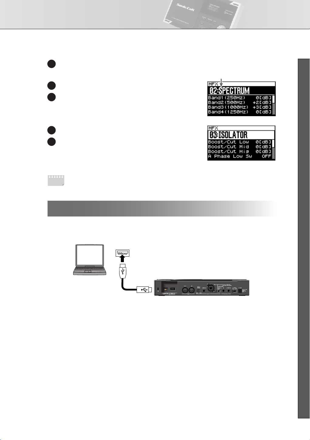
Editing effects .................................................................................................75
Selecting the item to edit (Effect Routing screen).......................................................... 77
Editing the multi-effects related settings (MFX1–3/MFX1–3 Output screens).................... 78
Chorus-related settings (Chorus/Chorus Output screen) ...............................................78
Reverb-related settings (Reverb/Reverb Output screen) ................................................79
Changing how the multi-effects are combined (MFX Structure screen) ............................80
Selecting how effects will operate (Effect Source screen).............................................. 80
Using MIDI to control the multi-effects (MFX1–3 Control screens)................................... 81
Using the SonicCell in Patch Mode ........................................................ 82
Viewing the Patch Play screen.........................................................................82
If the patch type is Patch.......................................................................................... 82
If the patch type is Rhythm Set.................................................................................. 83
Viewing the menu screen (Patch Menu screen) .................................................84
Switching the sound mode (Sound Mode screen) .............................................. 84
Selecting patches from a patch list................................................................... 85
Selecting patches from a patch list by category (Patch List (Ctg) screen)......................... 85
Selecting patches from a patch list by group (Patch List (Grp) screen)............................86
Selecting a rhythm set from a list (Rhythm Set List screen) .............................................87
Editing patches (Patch Edit screen) ...................................................................88
Overall settings for the entire patch (Patch General screen)..........................................90
Selecting how tones are combined (Patch Structure screen).......................................... 93
Settings for matrix control (Patch Mtrx Ctrl1–4 screens) ...............................................95
Waveform-related settings (Patch WG/Patch Pitch Env screen)..................................... 98
TVF settings (Patch TVF/Patch TVF Env screen).......................................................... 102
TVA settings (Patch TVA/Patch TVA Env screen) .......................................................105
Patch/Tone output-related settings (Patch Output screen)............................................108
LFO settings (Patch LFO1, 2/Patch Step LFO screen).................................................109
Specifies how the tones will be heard (Patch TMT screen) ..........................................112
Controller-related settings (Patch Ctrl screen) ............................................................114
Tone Copy.................................................................................................... 115
Patch Initialize ..............................................................................................115
Patch Write ..................................................................................................116
Editing rhythm sets (Rhythm Edit screen) ........................................................117
Edits overall settings for the entire rhythm set (Rhythm General screen) ........................118
Waveform-related settings (Rhythm Wave screen).....................................................120
Specifying how a rhythm tone will be heard (Rhythm WMT screen) ............................122
Pitch-related rhythm tone settings (Rhythm Pitch/Rhythm Pch Env screen) ......................122
TVF settings (Rhythm TVF/Rhythm TVF Env screen).....................................................124
TVA settings (Rhythm TVA/Rhythm TVA Env screen) ..................................................127
9
Page 10

Contents
Output-related settings for the rhythm set and rhythm tones (Rhythm Output screen)....... 129
Rhythm Tone Copy........................................................................................ 130
Rhythm Tone Initialize................................................................................... 130
Rhythm Set Initialize .....................................................................................130
Rhythm Set Write.......................................................................................... 131
Editing the effects (Patch/Rhythm Set) ............................................................132
Selecting the item to edit (Effect Routing screen)........................................................ 134
Multi-effect settings (MFX/MFX Output screen).......................................................... 134
Chorus settings (Chorus/Chorus Output screens) ......................................................135
Reverb settings (Reverb/Reverb Output screens) .......................................................136
Controlling the multi-effects via MIDI (MFX Control screen)......................................... 137
Audio Connections 139
Using the SonicCell with your computer (USB AUDIO).......................... 140
Basic operation............................................................................................. 140
Accessing the Menu screen............................................................................ 141
Inputting sound from an external device (INPUT)................................. 142
Basic operation............................................................................................. 142
Accessing the Menu screen............................................................................ 143
Input/output and effect settings (In/Out Routing)................................. 144
Selecting the item to edit (In/Out Routing screen) ...........................................147
Input effect settings (Input Effect/Input FX Output screen)................................ 147
Selecting the signal sent to your computer (To Computer screen) ..................... 148
Specifies how MFX3 will be used (MFX3 Location screen) ...............................149
Saving the MFX3 settings.......................................................................................149
System Write................................................................................................150
Using the plug-in version of SonicCell Editor
151
SONAR LE ......................................................................................... 152
SONAR 6.2 ....................................................................................... 157
Cubase 4........................................................................................... 160
Logic Pro 7.2 ..................................................................................... 163
10
Page 11

Contents
SMF/Audio File Player 167
Playing back songs............................................................................ 168
SMF/audio files that can be played ...............................................................168
Song playback .............................................................................................168
Selecting and playing a song from within a playlist ..................................................171
Playlist Write ................................................................................................173
Changing the song order ..............................................................................173
Deleting a song from the playlist ...................................................................173
Other Settings 175
System Settings.................................................................................. 176
General settings (System screen).................................................................... 176
Patch Scale Tune settings............................................................................... 178
Settings for the Preview function (System Preview screen) ...............................179
Settings for Control-related functions (System Control screen).......................... 179
MIDI-related settings (System MIDI screen) .....................................................180
Viewing information about SonicCell
(System SRX Info/System Version Info screens) ..............................................180
Editing the mastering effect (Mastering Effect screen) ......................................181
Utility functions.................................................................................. 182
Backing up user data (User Backup) ..............................................................182
Restoring backed-up data into the SonicCell (User Restore) .............................182
Returning to the factory settings (Factory Reset).............................................. 183
Initializing USB memory (USB Memory Format) .............................................. 183
Adjusting the overall tone of the audio output (Master Equalizer)......... 184
Appendices 185
Troubleshooting............................................................................................ 186
Error Messages............................................................................................. 191
Effects List..................................................................................................... 192
Performance List ........................................................................................... 222
Patch List ......................................................................................................223
Rhythm Set List .............................................................................................233
Waveform List ..............................................................................................242
MIDI Implementation..................................................................................... 246
Specifications................................................................................................ 278
Index ...........................................................................................................279
11
Page 12

Main Features
Superior Desktop Synthesizer
• 128-voice sound module with new sound set featuring true-to-life instruments
• Two SRX sound expansion slots for sound set personalization
USB Audio/MIDI Interface
• USB audio interface functionality w/MIC and GUITAR (Hi-Z) inputs
• Record using the professional on-board DSP effects
• PC/Mac VSTi/AU Editor and Cakewalk SONAR LE software included
Portable Backing Machine
• SMF, WAV, AIFF and MP3 playback capability via optional USBmemory is perfect for the gig
• Build playlists of any file-type combination using the playlist editor
12
Page 13

User Guide
13
Page 14
USER‘S GUIDE
Panel Descriptions
Top Panel
fig.kakubu-topPanel.eps
Display
Various information is shown
here according to your operations.
SRX Slot
You can install SRX series wave
expansion boards here.
•
Installation → p. 46
•
Selecting a wave → p. 98
USB MEMORY ACCESS Indicator
This will light when you’re playing song data from
USB memory that's connected to the SonicCell,
or when you're saving data to USB memory.
MIDI MESSAGE Indicator
MIDI
This will light when MIDI messages are being received
from a MIDI device connected to the MIDI IN connector.
USB
This will light when MIDI messages are being received
from the connected computer.
14
SMF/AUDIO PLAYER Buttons
Press these buttons when you’re using
the SonicCell as an SMF/audio player.
• Playing a song → p. 28, p. 168
• Creating a playlist → p. 30
MENU Button
You can press this button to switch to a menu
screen for the current mode or editing screen.
• The menu screen of each main mode
→ p. 59, p. 68, p. 76, p. 84, p. 88, p. 117, p. 133,
p. 141, p. 143, p. 146, p. 169, p. 171, p. 181
(Play/Pause) Button
Plays/pauses the song data.
EXIT Button
Press this button to cancel
an operation.
Page 15
Panel Descriptions
■ USER’S GUIDE
MIDI INST Button
Press this button when you
want to use the SonicCell as
a MIDI sound module.
• MIDI connections → p. 22, p. 54
• Performance → p. 22, p. 58
• Patch → p. 23, p. 82
PART VIEW Button
If the MIDI sound module is in Performance
mode (p. 54), press this button when you
want to make settings for each part.
By pressing this button together with
the [MIDI INST] button, you can switch
between Performance mode and Patch mode.
CURSOR/VALUE Dial
Use this to move the cursor, select
a parameter, or edit a value.
Press the dial to confirm the value.
• How to use [CURSOR/VALUE] → p. 20
■
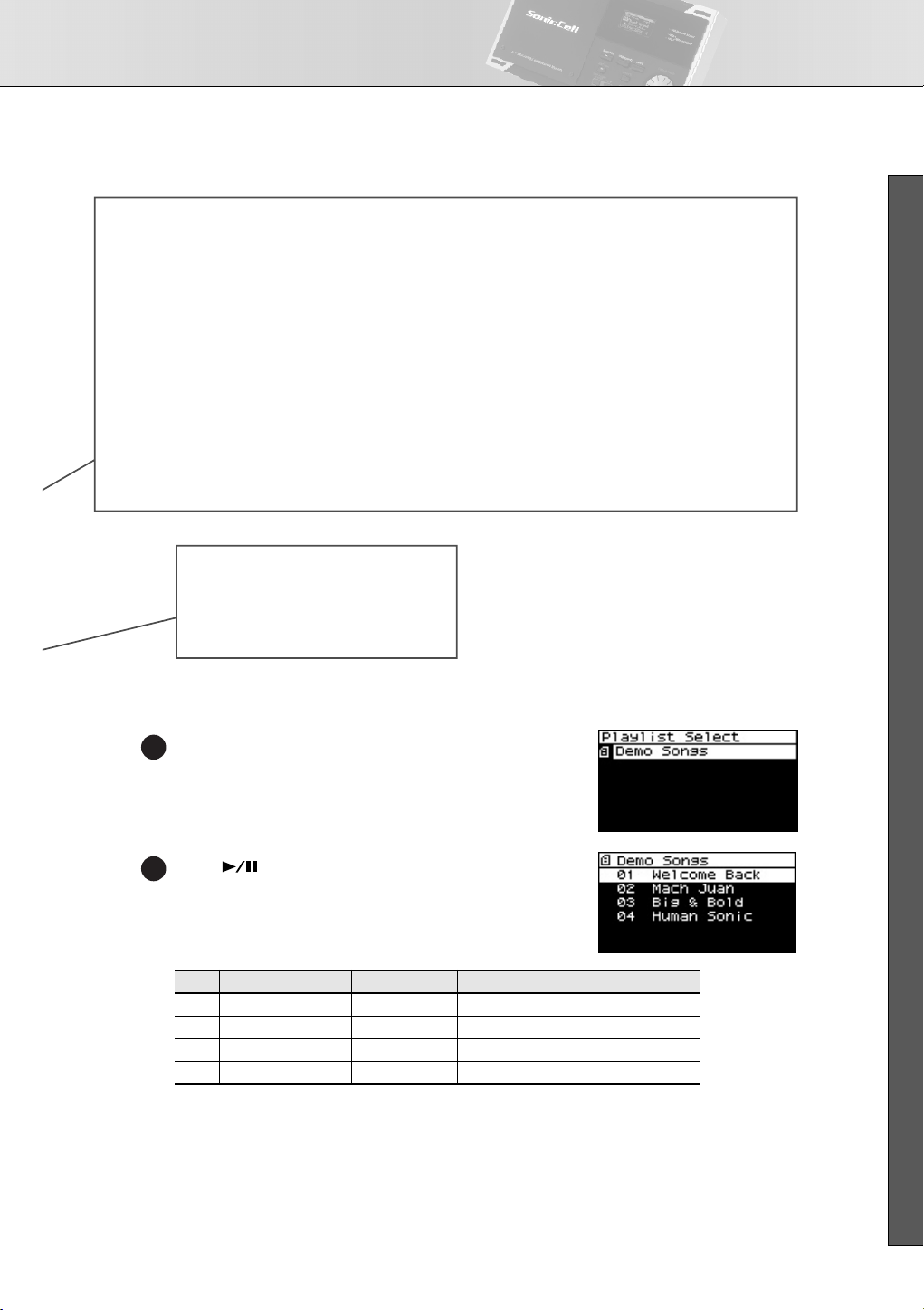
Playing the Demo Songs
fig.disp-plylstslct-demo.eps
Press [SMF/AUDIO PLAYER].
1
USB AUDIO Button
Press this button when you
want to apply an effect to the
audio signal from the connected
computer, or to make
output-related settings.
• USB AUDIO → p. 140
EFFECTS Button
Press this button when you want to make effect-related settings.
• Applying effects to a performance → p. 78
• Applying effects to a patch → p. 26, p. 132
• Applying effects to the signal from the Input jack → p. 43
INPUT Button
Press this button when you want to
apply an effect to the signal from a
device connected to the INPUT jack,
or to make output-related settings.
• Recording a mic or guitar → p. 40
• Inputting sound from an external
device → p.142
fig.disp-demosongs.eps
Press [ ].
2
Playback will start from the first song.
No.
Title Composer
1
Welcome Back Yo Sakaue © 2007 Roland Corporation
Copyright
2 Mach Juan Adrian Scott © 2007 Roland Corporation
3 Big & Bold Scott Tibbs © 2007 Roland Corporation
4 Human Sonic YUHKI © 2007 Roland Corporation
* If USB memory containing song file is connected, select [Demo Songs] in the playlist list screen. For details on
playing from a playlist, refer to p. 28.
981a
* All rights reserved. Unauthorized use of this material for purposes other than private, personal enjoyment is a
violation of applicable laws.
982
* No data for the music that is played will be output from MIDI OUT.
15
Page 16
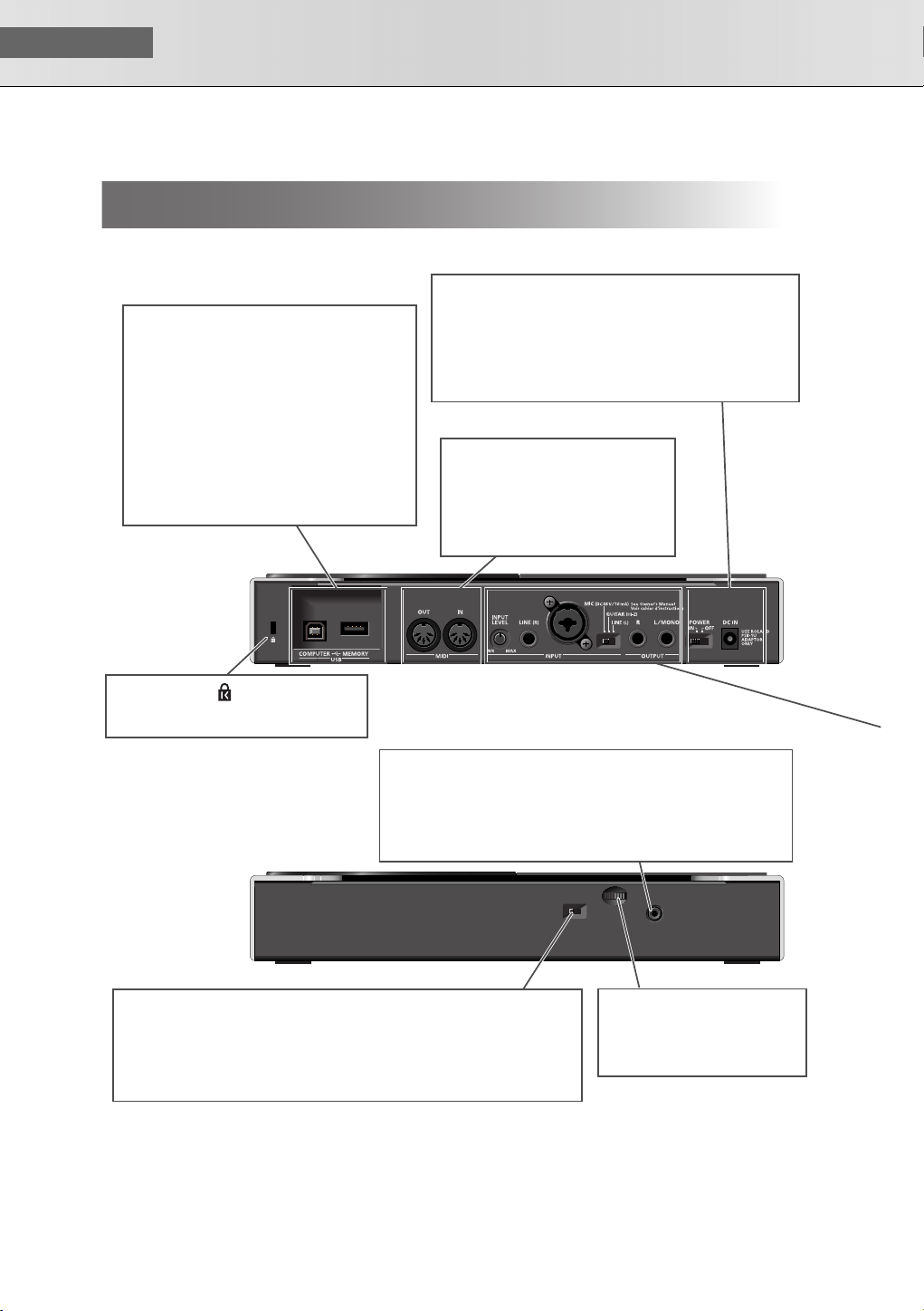
USER‘S GUIDE
Rear and Front Panels
fig.kakubu-rearPanel.eps
USB COMPUTER Connector
Use a USB cable to connect your computer here.
This connection can handle both MIDI and audio.
• Using the SonicCell with your computer
→ p.31, p.135
USB MEMORY Connector
You can connect USB memory here and
use the SonicCell to play back files (songs)
that have been stored on USB memory.
• Playing back songs → p.28, p.167
Rear Panel
Security Slot
http://www.kensington.com
Front Panel
POWER Switch
Turns the power on/off
(p. 18).
MIDI IN/OUT Connectors
You can connect these to other MIDI
equipment to send and receive MIDI
messages.
• Using the SonicCell as a MIDI
sound module → p. 22, p. 54
PHONES Jack
This is a stereo mini-type jack for connecting headphones.
This jack will output the sound received from the INPUT jack
mixed with the sound from the USB-connected computer and
the sound from the SonicCell itself.
Connecting headphones will not mute the sound from the OUTPUT jack.
DC IN Jack
Connect the included AC adaptor
here (p. 18). Do not use any AC
adaptor other than the included
one; doing so may cause
malfunctions.
16
SAMPLING RATE Switch
This specifies the sampling rate used to record or play back audio data.
After changing this setting, you’ll need to turn the SonicCell’s power off,
then on again. If you’re using software, you’ll also need to restart your software.
Be sure to set the [SAMPLING RATE] switch to match the sampling rate setting of
the software you’re using.
MASTER VOLUME Dial
This adjusts the volume of the
signals output from the PHONES
jack and OUTPUT jacks (p. 19).
Page 17
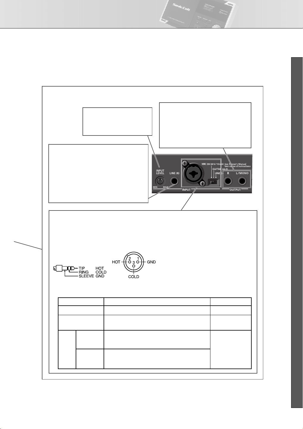
INPUT/OUTPUT Jacks
These jacks input or output audio signals.
INPUT LEVEL Knob
Adjusts the input level of the
signal received at INPUT.
• Adjusting the input level → p. 42
LINE (R) Jack
When using LINE (L) and LINE (R) for stereo input,
input the signal for the R channel here.
* If you’re inputting in mono, connect it to the
LINE (L) jack.
You can’t use this jack if the INPUT gain select
switch is not at the LINE (L) position.
• Recording a mic or guitar → p. 40, 142
Panel Descriptions
■ USER’S GUIDE
OUTPUT Jacks (R, L/MONO)
These jacks output the audio signal.
If you’re outputting in mono, connect to the
L/MONO jack.
These jacks output the combined signals of the
sound received from INPUT, the sound from the
USB-connected computer, and the sound from
the SonicCell itself.
L/GUITAR/MIC Jack (combo input jack)
You can connect either a mic, guitar, or line equipment here.
This instrument is equipped with balanced (XLR/TRS) type
jacks. Wiring diagrams for these jacks are shown below.
Make connections after first checking the wiring diagrams
of other equipment you intend to connect.
Switch
LINE
GUITAR
Dynamic
MIC
Condenser
Plug/connector accepted
1/4“ phone plug (unbalanced)
1/4“ phone plug (unbalanced)
(High impedance supported)
1/4“ phone plug (balanced or unbalanced),
XLR connector
* Switch OFF “Phantom Power“ in the INPUT screen.
XLR connector (48 V phantom power supported)
Connecting a phantom-powered condenser mic
→In the INPUT screen, turn “Phantom Power” on (p.142)
INPUT SOURCE Switch
Set this as appropriate for the device you’ve
connected to the LINE (L) jack.
If you’ve connected your source to the LINE (R)
jack, you must set this switch to LINE (L).
LINE (L):
Connect a line-level device such as an audio
device (e.g., CD player) or keyboard.
GUITAR (Hi-Z):
Connect an electric guitar that’s not being
sent through an effects processor
(high-impedance connection).
MIC:
Connect a mic.
• Recording a mic or guitar → p. 40, 142
Nominal input level
-30 – -10 dBu
-30 – -10 dBu
-50 – -30 dBu
17
Page 18
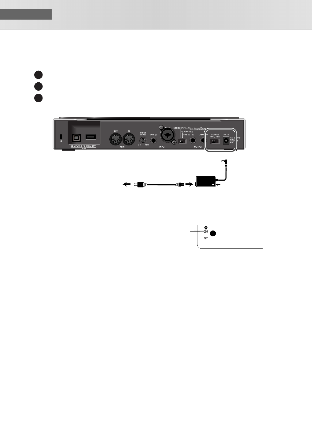
USER‘S GUIDE
■
Turning the Power On/Off
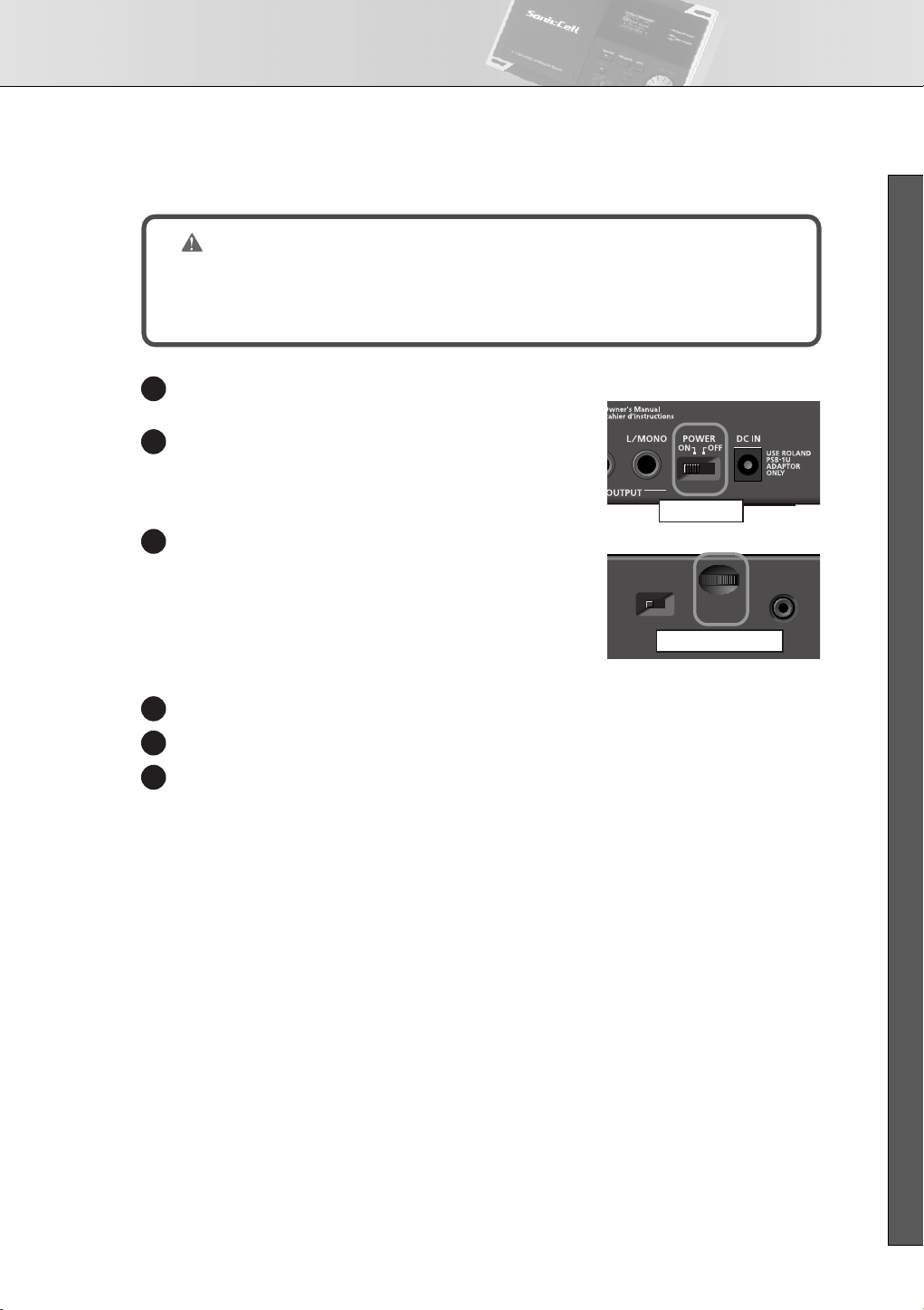
Connecting the AC Adaptor
Make sure that the [POWER] switch is off.
1
Connect the included power cord to the included AC adaptor.
2
Connect the AC adaptor to the SonicCell’s DC IN connector, and plug the power cord into an AC
3
outlet.
fig.AC-setsuzoku.eps
DC IN
Place the AC adaptor so that its lamp light is on the top side.
(it lights up when connected to an AC outlet)
AC Outlet
fig.AC-setchi.eps
* Depending on the circumstances of a particular
setup, you may experience a discomforting sensation, or perceive that the surface feels gritty to the
touch when you touch this device, microphones
connected to it, or the metal portions of other
objects, such as guitars. This is due to an infinitesimal electrical charge, which is absolutely harmless. However, if you are concerned about this,
connect the ground terminal (see figure) with an
external ground. When the unit is grounded, a
slight hum may occur, depending on the particulars of your installation. If you are unsure of the
connection method, contact the nearest Roland
Service Center, or an authorized Roland distributor, as listed on the “Information” page.
Power Cord
AC Adaptor
(PSB-1U)
SonicCell Bottom Panel
Ground
Terminal
Lamp
Unsuitable places for connection
• Water pipes (may result in shock or electrocution)
• Gas pipes (may result in fire or explosion)
• Telephone-line ground or lightning rod (may be dangerous in the event of lightning)
* When turning the unit upside-down, get a bunch of newspapers or magazines, and place them under
the four corners or at both ends to prevent damage to the buttons and controls. Also, you should try to
orient the unit so no buttons or controls get damaged.
* When turning the unit upside-down, handle with care to avoid dropping it, or allowing it to fall or tip
over.
18
Page 19
Turning the Power On/Off
■
Turning the Power On
NOTE
Once the connections have been completed, turn on power to your various devices in the order
specified. By turning on devices in the wrong order, you risk causing malfunction and/or damage to speakers and other devices.
fig.PowerOn.eps
Minimize the volume of the SonicCell and of your con-
1
nected audio equipment.
Turn on the [POWER] switch.
2
* This unit is equipped with a protection circuit. A brief interval
(a few seconds) after power up is required before the unit will
operate normally.
Use the [MASTER VOLUME] knob to adjust the volume.
3
■
Turning the Power Off
Rear Panel
POWER Switch
Front Panel
MASTER VOLUME Knob
■ USER’S GUIDE
Minimize the volume of the SonicCell and of your connected audio equipment.
1
Turn off the power of your connected audio equipment.
2
Turn off the [POWER] switch.
3
The indications in the display will disappear, and the power will turn off.
19
Page 20
USER‘S GUIDE
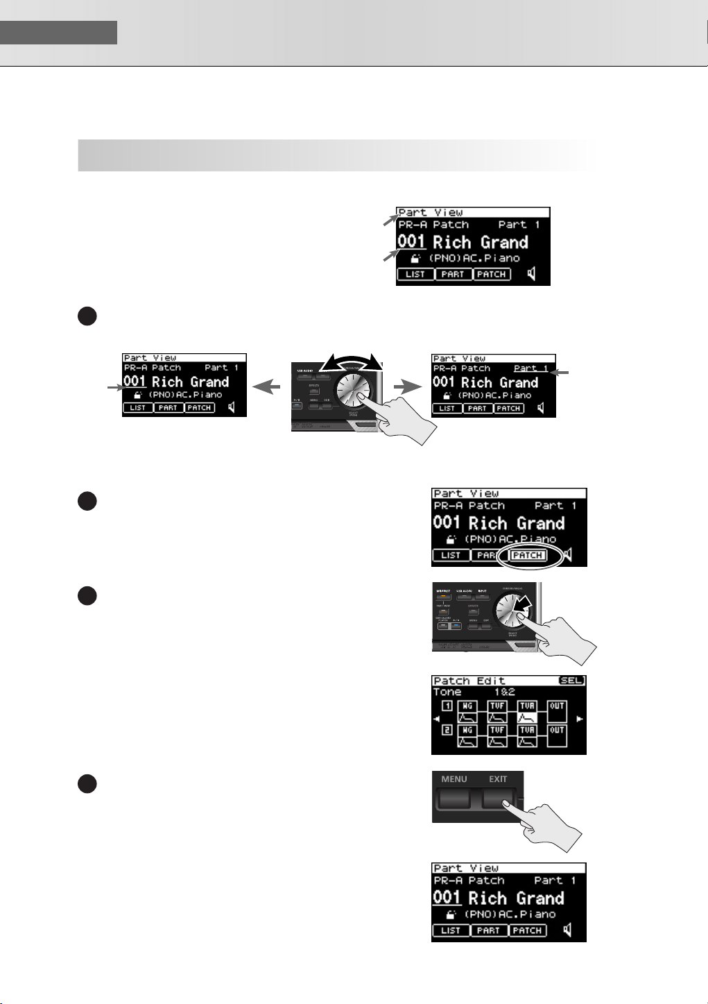
We’ll explain this using the Performance mode Part View screen as an example.
Accessing the Part View Screen
After turning the power on, make sure that [MIDI
INST] is lit, then press [PART VIEW].
Moving the Cursor
Basic Operation of the SonicCell
About the display and [CURSOR/VALUE]
fig.display-sample.eps.
the Name of
the display
Cursor
The cursor will move when you turn [CURSOR/VALUE].
1
cursor.eps
Turn
Cursor
Moving Between Screens
fig.dispCursor3.eps
Turn [CURSOR/VALUE] to move the cursor to [PATCH].
1
fig.cursor-push-eps
Press [CURSOR/VALUE].
2
fig.disp-PatchEdit.eps
The Patch Edit screen will appear.
fig.exit-push.eps
Press [EXIT].
3
Cursor
Press
Press
20
fig.disp-cursor.eps
You’ll return to the Part View screen.
Page 21
Basic Operation of the SonicCell
Editing a Value
fig.dispCursorValue1
Let’s try changing the patch number.
Turn [CURSOR/VALUE] to move the cursor
1
to the patch number.
fig.cursor-push-eps
Press [CURSOR/VALUE].
2
fig.dispCursorValue2
fig.cursor-turn.eps
The patch number will be highlighted.
Turn [CURSOR/VALUE].
3
■ USER’S GUIDE
Patch Number
Cursor
Press
The value at the
cursor is
highlighted
Turn
fig.dispCursorValue3
The value will change.
When you edit the value, an “E” symbol may
appear in the upper right of the screen.
In this case, you can save the settings you’ve
edited.
Saving perfoemances
➝
Refer to “Performance Write (p. 73 ).”
fig.disp-cursorValue4.eps
Press [CURSOR/VALUE] once more.
1
4
The cursor will return to its original state.
Shown when you
edit the value
The value
will change
21
Page 22
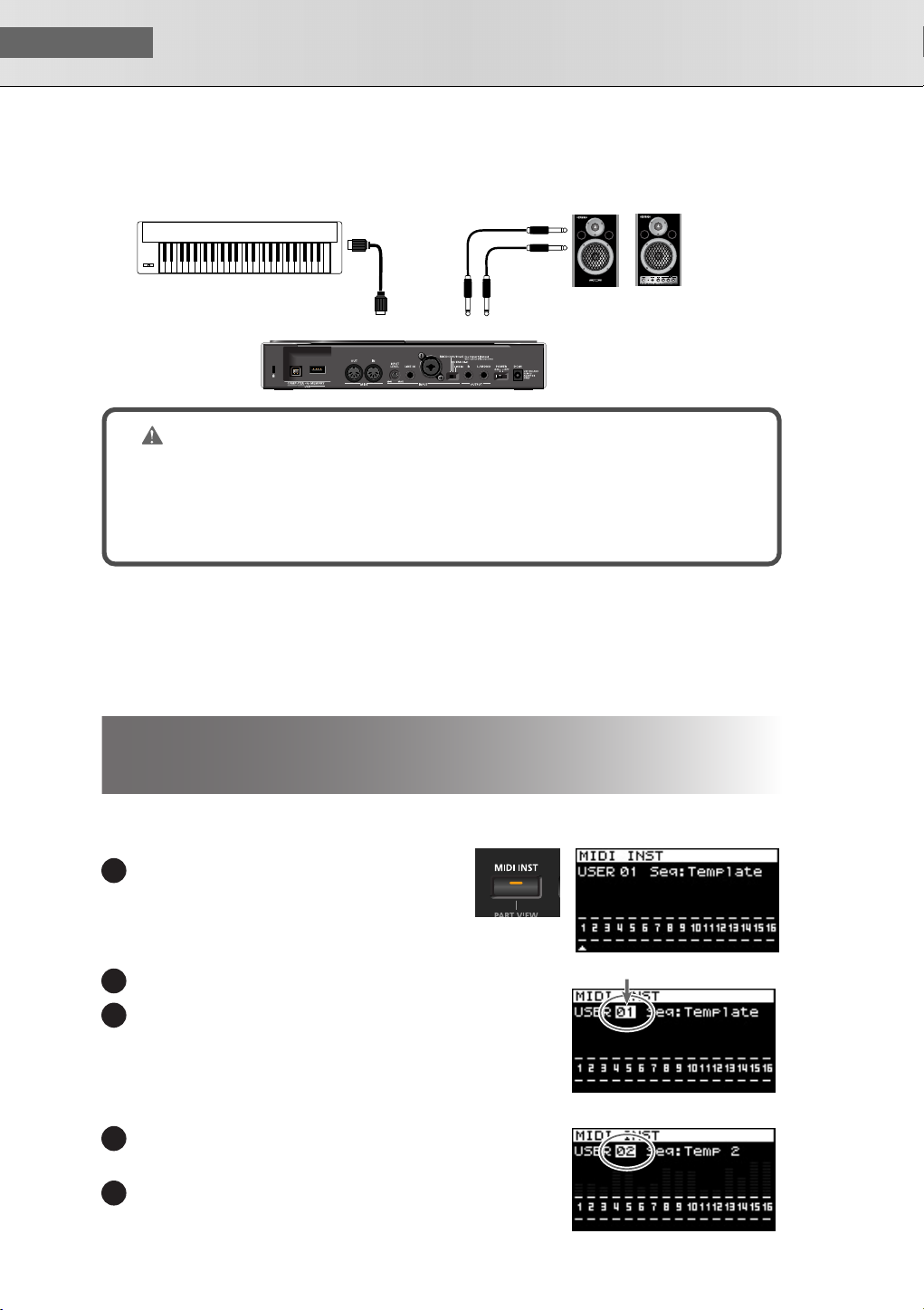
USER‘S GUIDE
Performance Number
■
Using the SonicCell as a MIDI Sound Module
Connections
fig.setsuzoku-MIDI.eps
MIDI OUT
MIDI Keyboard
MIDI IN
OUTPUT
Monitor Amplifier etc.
NOTE
To prevent malfunction and/or damage to speakers or other devices, always turn down the volume, and turn off the power on all devices before making any connections.
When connection cables with resistors are used, the volume level of equipment connected to the
inputs (INPUT) may be low. If this happens, use connection cables that do not contain resistors.
■
Performance mode and Patch mode
When using the SonicCell as a MIDI sound module, either Performance mode or Patch mode can be
selected.
When the power is turned on, Performance mode is selected.
For details on Performance mode and Patch mode, refer to p. 54 .
Playing the SonicCell in Performance Mode
■
Selecting a Performance
fig.button-MIDI-INST-Lite.epsfig.disp-MIDIINST.eps
Press [MIDI INST] so its indicator is lit.
1
The MIDI INST screen will appear.
fig.dispMIDIInst1.eps
Move the Cursor to the Performance Number.
2
Press [CURSOR/VALUE].
13
The value at the cursor will be highlighted.
For details on using [CURSOR/VALUE], refer to p. 20 .
fig.dispMIDIPrfmNum2.eps
Turn [CURSOR/VALUE] to change the performance number.
14
The sound will change.
Press [CURSOR/VALUE].
15
22
Page 23
Using the SonicCell as a MIDI Sound Module
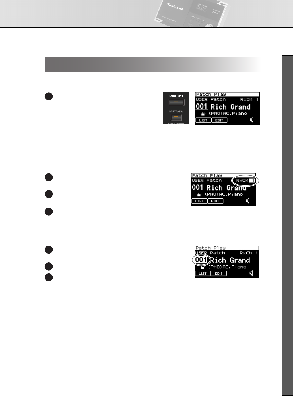
Playing the SonicCell in Patch Mode
■
Selecting Patch Mode
fig.button-MIDI-PART.eps/fig.disp-PatchPlay.eps
In the MIDI INST screen, simultaneously press
1
[MIDI INST] and [PART VIEW].
The SonicCell will enter Patch mode, and the
Patch Play screen will appear.
If you once again hold down [MIDI INST] and
press [PART VIEW], you’ll switch to Performance mode, and the MIDI INST screen will
appear.
■
Setting the MIDI channel
fig.dispPtchPlyRxch.eps
In the Patch Play screen, turn [CURSOR/VALUE] to move
1
the cursor to “RxCh.”
Press [CURSOR/VALUE].
2
The RxCh value will be highlighted.
Turn [CURSOR/VALUE] to set the “RxCh” value to match
3
the transmit channel of the connected equipment.
■ USER’S GUIDE
■
Selecting Sounds
fig.dispPtchSelect.eps
In the Patch Play screen, turn [CURSOR/VALUE] to move
1
the cursor to the patch number.
Press [CURSOR/VALUE].
2
Turn [CURSOR/VALUE] to change the patch number.
3
The sound will change.
23
Page 24
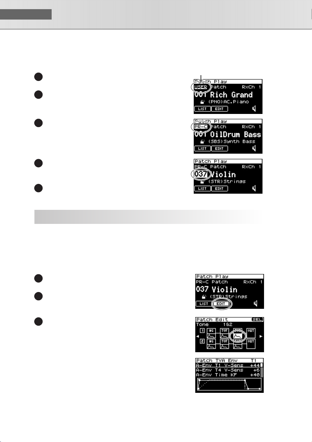
USER‘S GUIDE
Example: Selecting “037 Violin” from the “PR-C” group
fig.dispPtchSlct01.eps
In the Patch Play screen, turn [CURSOR/VALUE] to move the
1
cursor to the patch group.
Press [CURSOR/VALUE].
2
fig.dispPtchSlct02.eps
Turn [CURSOR/VALUE] to select “PR-C,” then press [CURSOR/
13
VALUE].
fig.dispPtchSlct03.eps
Turn [CURSOR/VALUE] to move the cursor to the patch num-
4
ber, then press [CURSOR/VALUE].
The patch number will be highlighted.
Turn [CURSOR/VALUE] to select “037” as the patch number.
5
“Violin” will be selected.
Patch Group
Modifying the Sound (editing a patch)
Before you continue, select “037 Violin” from “PR-C” as described in the procedure above.
■
Editing the Amp Envelope
This specifies how the sound begins and decays.
Access the Patch Edit Screen
fig.dispPtchPly-Edithanten.eps
In the Patch Play screen, use [CURSOR/VALUE] to move the cor-
1
sor to the “EDIT.”
Press [CURSOR/VALUE].
2
The Patch Edit screen will appear.
fig.dispPtchEdtTVA.eps
Turn [CURSOR/VALUE] to select the graphic below Tone 1
3
“TVA,” then press [CURSOR/VALUE].
fig.disp-PatchTVAEnv.eps
The Patch TVA Envelope (T1) screen will appear.
24
Page 25
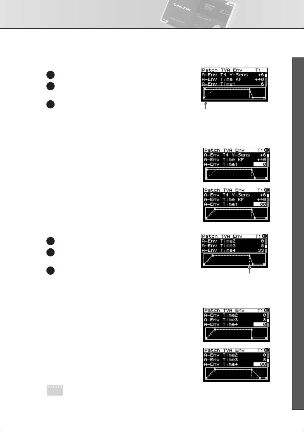
Using the SonicCell as a MIDI Sound Module
T1(when you press a key)
T4 (when you release a key)
Adjusting the Attack
fig.dispTVAEnv.eps
Turn [CURSOR/VALUE] to move the cursor to “A-Env Time1.”
4
Press [CURSOR/VALUE].
5
The value will be highlighted.
Turn [CURSOR/VALUE] to change the value, then press [CUR-
6
SOR/VALUE].
When you change the value, the graph in the lower part of the
screen will also change.
If you press [EXIT] you’ll return to the previous screen.
fig.disp-TVAEnvT1h1.eps
•
To make the sound begin immediately when you press a
key
➝
Set “A-Env Time1” to a low value
fig.disp-TVAEnvT1h2.eps
•
To make the sound begin slowly when you press a key
➝
Set “A-Env Time1” to a high value
Adjusting the Release
fig.dispTVAEnvT4.eps
Turn [CURSOR/VALUE] to move the cursor to “A-Env Time4.”
7
■ USER’S GUIDE
8
9
MEMO
Press [CURSOR/VALUE].
The value will be highlighted.
Turn [CURSOR/VALUE] to change the value, then press [CURSOR/VALUE].
When you change the value, the graph in the lower part of the
screen will also change.
If you press [EXIT] you’ll return to the previous screen.
fig.disp-TVAEnvT4h1.eps
•
To make the sound stop immediately when you release a
key
➝
Set “A-Env Time4” to a low value
fig.disp-TVAEnvT4h2.eps
•
To make the sound linger after you release a key
➝
Set “A-Env Time1” to a high value
For details on amp envelope, refer to p. 107 .
If you want to save the patch you modified, refer to p. 116 .
25
Page 26
USER‘S GUIDE
■
By editing the filter settings you can make the tonal character of the sound brighter or darker.
MEMO
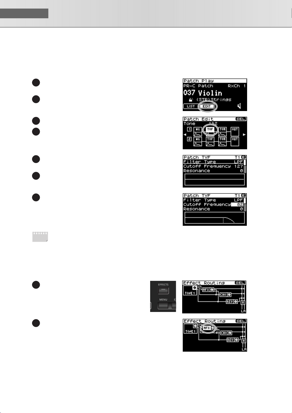
Editing the Filter
fig.dispPtchPly-Edithanten.eps
In the Patch Play screen, turn [CURSOR/VALUE] to move the cur-
1
sor to the “EDIT.”
Press [CURSOR/VALUE].
2
The Patch Edit screen will appear.
fig.dispPtchEdtTVF.eps
Turn [CURSOR/VALUE] to move the cursor to the “TVF.”
3
Press [CURSOR/VALUE].
4
The Patch TVF screen will appear.
fig.disp-PatchTVF1.eps
Turn [CURSOR/VALUE] to move the cursor the “Cutoff Fre-
5
quency.”
Press [CURSOR/VALUE].
6
The value will be highlighted.
fig.disp-PatchTVF-Cutoff.eps
Turn the [CURSOR/VALUE] to edit the value, and then press
7
[CURSOR/VALUE].
When you change the value, the graph in the lower part of the
screen will also change.
If you press [EXIT] you’ll return to the preceding screen.
For details on filter, refer to p. 102 .
If you want to save the patch you modified, refer to p. 116 .
■
Changing the Effect
Effects are various types of processing that you can apply to the sound. You can dramatically vary the character of the sound simply by changing the effect.
fig.button-EFFECTS.epsfig.disp-EfxRouting.eps
In the Patch Play screen, press [EFFECTS].
1
The Effect Routing screen will appear.
fig.dispEfxRtF1.eps
Turn [CURSOR/VALUE] to move the cursor “MFX.”
2
fig.dispMFX.eps
26
Page 27
Using the SonicCell as a MIDI Sound Module
MFX Type
Press [CURSOR/VALUE].
3
fig.disp-MFX.eps
The MFX screen will appear.
Use [CURSOR/VALUE] to select the MFX type.
4
Press [CURSOR/VALUE].
5
The MFX type indication will be highlighted.
Use [CURSOR/VALUE] to change the MFX type.
6
Press [CURSOR/VALUE].
7
If you press [EXIT] you’ll return to the preceding screen.
MEMO
For details on effect editing, refer to p. 132 .
If you want to save the patch you modified, refer to p. 116 .
Using the Editor and Librarian
Connections
fig.setsuzoku-MIDI-editor.eps
Computer
To USB Connector
of Computer
■ USER’S GUIDE
USB COMPUTER
USB cable
Dedicated editor and librarian software is included with the SonicCell.
By using the editor you can edit the SonicCell’s performance and patch parameters on your computer.
You can edit the settings while viewing them in the large screen of your computer.
By using the librarian you can manage the edited settings on your computer.
For details on installing the software, refer to p. 31 .
For details on using the software, refer to the PDF manual that is installed along with the software.
27
Page 28
USER‘S GUIDE
The SonicCell can play back MIDI files (SMF) and audio files (WAV, AIFF, MP3).
This is a convenient function that you can also use to play backing tracks during a live performance.
■
Playing Songs
Connections
fig.setsuzoku-pbm.eps
(Portable Backing Machine)
* Save the song data in
the root directory of
your USB memory.
* Use only USB memory sold by Roland. Operation cannot be guaranteed when products other than there is
used. Proper operation cannot be guaranteed if other USB memory products is used.
* Connect the USB memory after the SonicCell’s power is turned on.
* If, after a USB memory device has been removed, you decide that you want to connect it again, you’ll need
to switch the SonicCell’s power off, then switch it back on again.
USB
MEMORY
SMF, WAV,
AIFF, MP3
Monitor Amplifier etc.
OUTPUT
NOTE
To prevent malfunction and/or damage to speakers or other devices, always turn down the volume, and turn off the power on all devices before making any connections.
When connection cables with resistors are used, the volume level of equipment connected to the
inputs (INPUT) may be low. If this happens, use connection cables that do not contain resistors.
■
File Formats that You Can Play
For details on the file formats that you can play, refer to p. 168 .
■
Playing the Demo Songs
Refer to p. 15.
28
Playback Procedure
Before you continue, make sure that the USB memory containing the song file you want to play is connected
to the SonicCell.
You should also make sure that the SonicCell is set to Performance mode (p. 60 ).
* When saving song file on your USB memory, be sure to save it in the root directory. Songs saved in the root
directory will be saved in the “USB Memory” playlist.
fig.button-PBM.eps
Press [SMF/AUDIO PLAYER].
1
The Playlist Select screen will appear.
fig.disp-PlyLstSlct-Root.eps
Turn [CURSOR/VALUE] to move the cursor to the “USB Memory.”
2
Page 29
Playing Songs (Portable Backing Machine)
Press [CURSOR/VALUE].
3
fig.disp-PlayListC.eps
A list of the songs in the USB memory will appear.
fig.disp-PlayListSong.eps
Turn [CURSOR/VALUE] to select a song, then press [CURSOR/
4
VALUE].
The selected song will be displayed.
* The song length indicated in the display may differ from the
actual song length.
fig.button-PBM.eps/fig.disp-song-play.eps
Press [ ].
5
The selected song will play.
Press [ ] to stop the song.
6
If you press [EXIT] you’ll return to the preceding screen.
About the Sampling Rate
fig.SmplRateSW.eps
The SonicCell will play songs that were saved with
the same sampling rate as the setting for the [SAMPLING RATE] switch on the front panel.
Songs whose sampling rate differs from the SonicCell’s setting will be shown in the list of songs, but
cannot be selected or played.
In this case, move the sampling rate switch to the
rate of the song you want to play, then turn the
SonicCell’s power off, then on again.
SAMPLING RATE
SWITCH
■ USER’S GUIDE
Change the setting of the [SAMPLING RATE] switch.
1
Switch off the SonicCell’s power, then turn it back on.
2
29
Page 30
USER‘S GUIDE
You can use the included “SonicCell Playlist Editor” to create a playlist for playback by the SonicCell.
If you want to use the SonicCell to play backing tracks, it’s convenient to create a playlist in the order you
want the songs to play.
For details on installing “SonicCell Playlist Editor,” refer to p. 31 .
For details on using the software, refer to the PDF manual that is installed along with the software.
Creating a Playlist
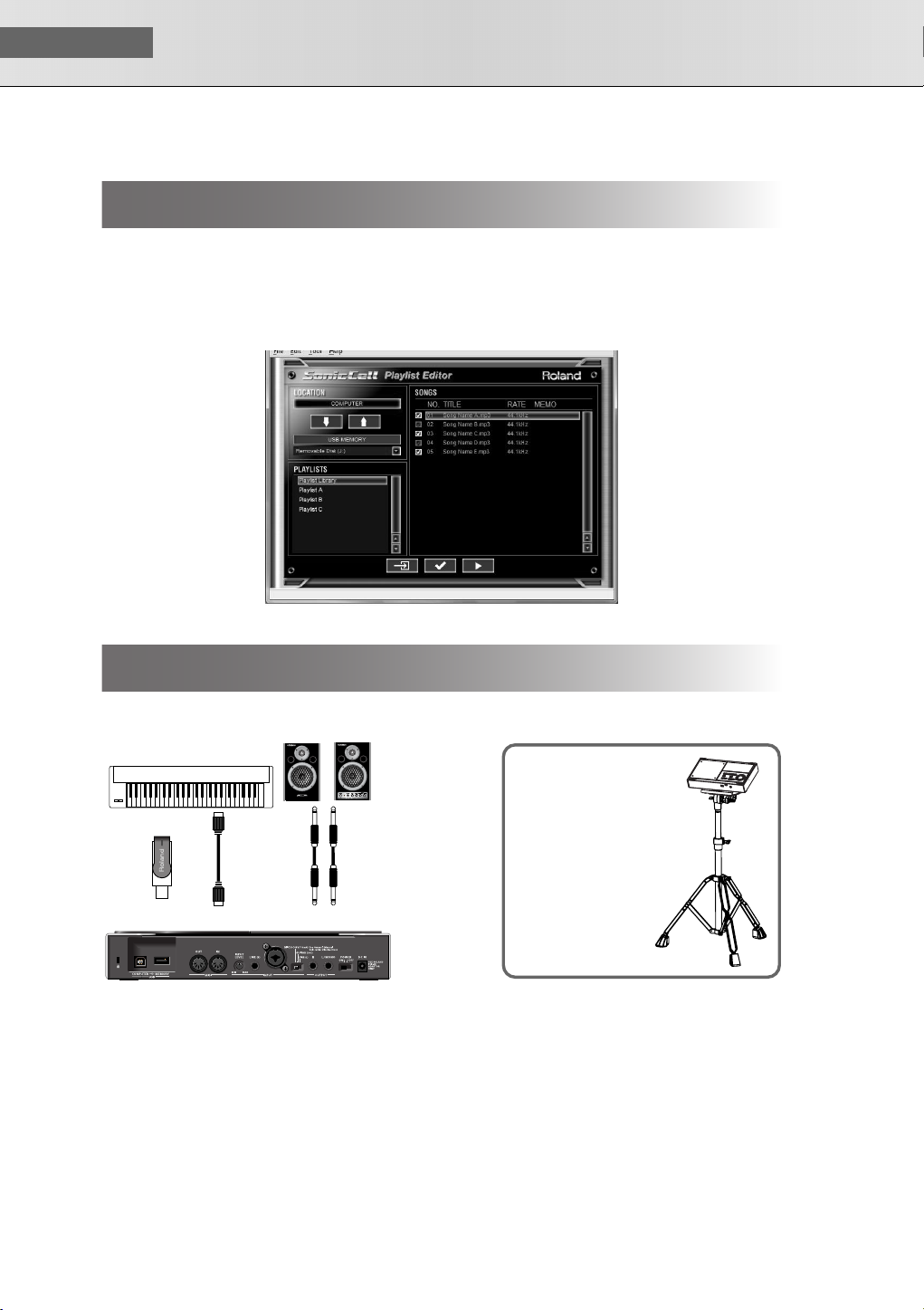
screen-playlisteditor.eps
Performing via MIDI while a Song Plays
■
Connections
fig.setsuzoku-pbm-MIDI.epsfig.setsuzoku-pds10.eps
MIDI Keyboard
USB
MEMORY
PDS-10 BKT-S
MIDI IN
MIDI OUT
Monitor Amplifier etc.
OUTPUT
By using the separately
available PDS-10 and
BKT-S, you can set up the
SonicCell as shown in the
illustration.
*If you use the PDS-10,
spread the tripod to the
maximum extent.
Ensure that the total
height including the
SonicCell does not
exceed one meter.
30
Page 31

Connecting the SonicCell to Your Computer
You can use the SonicCell as an external sound module for your DAW or sequencer software.
NOTE
You must install the driver before you connect the SonicCell to your computer.
■
Example Connections and Preparations for Installation
fig.setsuzoku-DAW.eps
Computer
To USB Connector
of Computer
Disconnect
Power off
USB cable
USB COMPUTER
Rear Panel
MIDI Keyboard
MIDI OUT
MIDI IN
OUTPUT
Monitor Amplifier etc.
In the System screen,
turn USB MIDI THRU
“ON” (p. 173)
Power off
■ USER’S GUIDE
Front Panel
Set the sampling rate to
44.1 kHz
NOTE
To prevent malfunction and/or damage to speakers or other devices, always turn down the volume, and turn off the power on all devices before making any connections.
When connection cables with resistors are used, the volume level of equipment connected to the
inputs (INPUT) may be low. If this happens, use connection cables that do not contain resistors.
NOTE
You may not rent or lease the software included with this product without the permission of the
copyright holder. Unauthorized duplication is forbidden by law.
31
Page 32

USER‘S GUIDE
dousa.eps
SonicCell Editor System Requirements
Windows OS
Windows : Microsoft® Windows® XP
CPU/Clock : Pentium®/Celeron® processor 1.4 GHz or higher
RAM : 512 MB or more
Hard Disk : 160 MB or more
Display/Colors : 1280 x 800 or higher/24 bit Full Color or
Others : A computer with a USB connector that supports USB
*Although Roland has tested numerous configurations, and has determined that on average, a computer
system similar to that described above will permit normal operation of the SonicCell Applications, Roland
cannot guarantee that a given computer can be used satisfactorily with the SonicCell Applications based
solely on the fact that it meets the left requirements. This is because there are too many other variables that
may influence the processing environment, including differences in motherboard design and the particular
combination of other devices involved.
*In the interest of product improvement, the specifications and/or contents of this package are subject to
change without prior notice.
■
Installation Procedure
Microsoft® Windows Vista™
* This does not work with the 64-bit Edition of
Windows Vista™.
more
Specification Revision 2.0 or higher
* Intel chipset is recommended.
* SonicCell may not perform to its full specs when used
with an added USB 2.0 interface card.
CD-ROM Drive
Mac OS
Operating System : Mac OS 10.4.3
CPU/Clock : PowerPC G4 1 GHz or
RAM : 512 MB or more
Hard Disk : 160 MB or more
Display/Colors : 1280 x 800 or
Others : Apple Macintosh series
computer with on-board USB
2.0
CD-ROM Drive
or later
higher/Intel processor
higher/1670 million
colors or more
Windows XP users................................... p. 33
Windows Vista users ............................... p. 35
Mac OS users........................................... p. 37
Installing SONAR LE .............................. p. 152
Specifications of the dedicated plug-in version of the editor
SonicCell Editor is provided in two forms: a stand-alone version and a plug-in version.
Plug-in Formats
• Windows: VSTi
• Mac: VSTi, Audio Unit
Host Applications in Which Operation has been Verified
If you’re using the plug-in version of the editor, please refer also to the applicable explanation.
• SONAR LE ➝ p. 152
• SONAR 6.2 ➝ p. 157
• CUBASE 4 ➝ p. 160
• Logic Pro 7.2 ➝ p. 163
* In order to use plug-in version of the editor, your computer must meet the above operating requirements as
well as the requirements of the host application you're using.
* The plug-in version of the editor has been tested and found to work with major host applications, but we can-
not guarantee that it will work with all host applications.
32
Page 33

Connecting the SonicCell to Your Computer
Windows XP users
In order to install the driver and software, you must log on as a user who has administrative privileges.
* For details, ask the system administrator of your computer.
NOTE
On the SonicCell Editor CD, the XP folder located inside the Driver folder contains a Readme
file (Readme_E.html), which explains how to install the driver and includes a number of troubleshooting tips. Be sure to read this file before using the software.
Installing the Driver
Start up Windows with all USB cables disconnected (except for a USB keyboard and/or mouse, if
1
used).
Log on to Windows as one of the following users.
2
• A user belonging to the Administrators group, such as Administrator
• A user whose account type is Computer Administrator
* For details, contact the system administrator of the computer you’re using.
■ USER’S GUIDE
Close all applications.
3
Also close any anti-virus or system-monitoring software.
Insert the “SonicCell Editor CD-ROM” into your CD-ROM drive, navigate to the Driver folder | XP
4
folder, and double-click Setup.exe.
The screen will indicate “Roland SonicCell Driver will be installed on your computer...”
5
Click [Next].
* If any other message is displayed, proceed as directed by the contents of the message.
The message “To begin installation, click [Next]” will appear. Proceed with the driver installation
6
as directed by the instructions in the screen.
33
Page 34

USER‘S GUIDE
■
These settings will prevent problems with the sound being interrupted when you play back audio from your
computer.
■
dows
Windows Settings
System Settings
Open “Control Panel” and double-click “System.”
1
* If you don’t see the above icon, click “Performance and Maintenance,” then click “System.”
Click the “Advanced” tab, and then in the Performance section click [Settings].
2
Click the “Advanced” tab.
3
Choose “Background services” and click [OK].
1
4
Click [OK] to close “System Properties.”
5
Settings for Using the Media Player Included with Win-
Open “Control Panel” and double-click “Sounds and Audio Devices.”
1
* If you don’t see the above icon, click “Sounds, Audio, and Audio Devices,” then click “Sounds and
Audio Devices.”
Click [OK] to close “Sounds and Audio Devices Properties.”
2
Start up Windows Media Player, play back an audio file and a MIDI file, and verify that you hear
3
the sound correctly.
Installing SonicCell Editor
Insert the “SonicCell Driver CD-ROM” into your CD-ROM drive, navigate to the Editor folder, and
1
double-click Setup.exe.
The “Welcome” screen will appear. Click [Next].
2
Follow the on-screen directions to install SonicCell Editor.
3
When you install SonicCell Editor, the SonicCell Editor, SonicCell Editor VSTi plugin, SonicCell Librarian, SonicCell Playlist Editor, and online manuals for each editor will be installed.
The online manual for each editor can be found under Windows “Start | All Programs |
SonicCell Editor” folder. The online manuals are provided as PDF files.
You’ll need Adobe Reader (available free of charge) in order to view PDF files.
34
Page 35

Connecting the SonicCell to Your Computer
Windows Vista Users
In order to install the driver and software, you must log on as a user who has administrative privileges.
* For details, ask the system administrator of your computer.
NOTE
The Driver | Vista folder of the SonicCell Driver CD-ROM contains a Readme file
(Readme_E.html) that describes driver installations and troubleshooting. Be sure to read this
before use.
Installing the Driver
Start up Windows with all USB cables disconnected (except for a USB keyboard and/or mouse, if
1
used).
■ USER’S GUIDE
Close all applications.
2
Also close any anti-virus or system-monitoring software.
Place the “SonicCell Editor CD” into your CD-ROM drive, navigate to the Driver folder | Vista
3
folder, and double-click Setup.exe.
* If the message “Drivers must be installed by an administrator user.” is displayed, log on to Windows as
a user whose account type is Administrator, and then perform the installation again.
A User Account Control screen will appear; click [Continue].
14
A message of “Roland SonicCell Driver will be installed on your computer...” will appear.
5
Click [Next].
* If any other message is displayed, proceed as directed by the contents of the message.
The message “Click [Next] to begin the installation” will appear. Proceed with the driver installa-
6
tion as directed by the instructions in the screen.
35
Page 36

USER‘S GUIDE
■
Windows Settings
Settings for using the Media Player included with Windows
Open “Control Panel,” click “Hardware and Sounds,” then click “Sounds.”
1
* If you’ve chosen the Classic View, double-click “Sounds.”
In “Playback,” choose Roland SonicCell’s “OUT” and click “Set Default.”
2
Click [OK] to close “Sounds.”
3
Start up Windows Media Player, play back an audio file, and verify that sound is produced cor-
4
rectly.
Installing SonicCell Editor
Insert the “SonicCell Editor CD-ROM” into your CD-ROM drive, navigate to the Editor folder, and
1
double-click Setup.exe.
The screen will indicate “An unidentified program is requesting access to this computer”; click
2
[Allow].
A User Account Control screen will appear; click [Continue].
3
The installer will start up. Follow the on-screen instructions to proceed with installing SonicCell
4
Editor.
When you install SonicCell Editor, the SonicCell Editor, SonicCell Editor VSTi plugin, SonicCell Librarian, SonicCell Playlist Editor, and online manuals for each editor will be installed.
The online manual for each editor can be found under Windows “Start | All Programs |
SonicCell Editor” folder. The online manuals are provided as PDF files.
You’ll need Adobe Reader (available free of charge) in order to view PDF files.
36
Page 37

Connecting the SonicCell to Your Computer
Mac OS X Users
In order to install the driver and other software, you must log on as a user who has an administrative
account.
* For details, ask the system administrator of the computer you’re using.
* The included SONAR LE is not compatible with Mac OS.
Installing the Driver
* If an “Authentication” dialog box appears during the installation, enter your password and click [OK].
Start up your computer with all USB cables disconnected (except for the keyboard and mouse).
1
Insert the “SonicCell Editor CD-ROM” into your CD-ROM drive, navigate to the Driver folder, and
2
double-click “SonicCellUSBDriver.pkg.”
You may see the message “This installer package needs to run a program to determine if it can
3
be installed. Do you want to continue?”
In this case, click [Continue].
■ USER’S GUIDE
A message will indicate “Welcome to Roland SonicCell Driver installer.”
4
Click [Continue].
A message will indicate “Select a Destination.”
5
Click to select the drive in which the system is installed, and then click [Continue].
A message will indicate “Easy install.”
6
Click either [Install] or [Upgrade].
A message will indicate “Installing this software requires you to restart...” Click [Continue with
7
installation].
A message will indicate “The software was successfully installed” will appear. Click [Restart] to
8
restart your computer.
37
Page 38

USER‘S GUIDE
Installing SonicCell Editor
In the “SonicCell Editor CD-ROM,” navigate to the Editor folder and double-click “SonicCell Edi-
1
torInstaller.mpkg.”
The installer will start up. Follow the on-screen instructions to proceed with installing SonicCell
2
Editor.
When you install SonicCell Editor, the SonicCell Editor, SonicCell Librarian, SonicCell Playlist Editor,
and online manuals for each editor will be installed.
The “Manual” folder within the folder where SonicCell Editor is installed contains
online manuals for each editor. The online manuals are provided as PDF files.
You’ll need Adobe Reader (available free of charge) in order to view PDF files.
Settings
■
Mac OS X Audio Input/Output Settings
Use a USB cable to connect the SonicCell to your computer, then switch on the SonicCell’s power.
1
In “System Preference,” click “Sounds.”
2
Choose “Roland SonicCell ** kHz” for the following settings.
3
(** will depend on the sampling rate setting of the SonicCell itself.)
• In the “Sound Effects” tab, “Play alerts and sound effects through:”
• In the “Output” tab, “Choose a device for sound output”
• In the “Input” tab, “Choose a device for sound input”
■
Mac OS X MIDI Input/Output Settings
Use a USB cable to connect the SonicCell to your computer, then switch on the SonicCell’s power.
1
In the “Applications - Utilities” folder, double-click “Audio MIDI Setup” to start it up.
2
Click the “MIDI Devices” tab.
3
38
Page 39

Connecting the SonicCell to Your Computer
In the “Audio MIDI Setup” dialog box, verify that “SonicCell” is shown.
24
* If “SonicCell” is not shown, or if it is shown grayed-out, the SonicCell was not detected correctly. Try
clicking “Re-scan MIDI.” You can also try switching off the SonicCell’s power, then turning it back on.
* If a different version of the driver had been installed, the old settings may still exist. In this case, click
the grayed-out “SonicCell” or “Roland SonicCell” to select it, and then click “Delete device” to delete
the settings.
Click “Add Device.” A “New External Device” item will appear.
5
Click added “New External Device” that was added, and then click “View Information.”
6
Enter the following names in the “Device Name” field of each “New External Device.”
7
First new external device SonicCell
Drag with the mouse so that the up/down arrows indicating the input/output ports are con-
8
nected as follows.
• Connect the first up/down arrow of “SonicCell” to the up/down arrow of the added “SonicCell”
Verify that MIDI transmission and reception is occurring normally.
9
• Click “Test Settings.” The mouse cursor will change to the shape of a musical note.
Click the added external device. If you hear sound from the sound module, the settings are cor-
10
rect.
Click ”Test Setup” once again to end the test.
11
Close the “Audio MIDI Settings” dialog box. This completes the settings.
12
■ USER’S GUIDE
■
Before You Use the SonicCell with Your Software
Use a USB cable to connect the SonicCell to your computer before you start up your software.
1
In the Audio Driver settings of the software you’re using, choose “Roland SonicCell ** kHz.”
2
(** will depend on the sampling rate setting of the SonicCell itself.)
In the MIDI Driver settings of the software you’re using, choose SonicCell.
3
For details, refer to the manual of the software you’re using.
39
Page 40

USER‘S GUIDE
■
Recording a Mic or Guitar
(USB/Audio Interface)
Connections
fig.setsuzoku-Input.eps
Computer
To USB Connector
of Computer
USB cable
USB COMPUTER
Dynamic Mic
Keyboard
LINE (R)
LINE (L)
MIC
INPUT
Guitar
GUITAR (Hi-Z)
Acoustic Guitar etc.
Condenser Mic
(DC 48 V/10mA)
MIC
Monitor Amplifier etc.
OUTPUT
Set the INPUT LEVEL knob to “MIN”
before making connections
NOTE
* To prevent malfunction and/or damage to speakers or other devices, always turn down the vol-
ume, and turn off the power on all devices before making any connections.
* When connection cables with resistors are used, the volume level of equipment connected to the
inputs (INPUT) may be low. If this happens, use connection cables that do not contain resistors.
* Howling could be produced depending on the location of microphones relative to speakers. This
can be remedied by:
1. Changing the orientation of the microphone(s).
2. Relocating microphone(s) at a greater distance from speakers.
3. Lowering volume levels.
fig.XLR/TRSJack.eps
* This instrument is equipped with bal-
anced (XLR/TRS) type jacks. Wiring
diagrams for these jacks are shown
below. Make connections after first
checking the wiring diagrams of
other equipment you intend to connect.
40
Page 41

Recording a Mic or Guitar (USB/Audio Interface)
Connecting a Mic
Dynamic Mic
Acoustic Guitar etc.
Condenser
Mic
L/GUITAR/MIC
Input Source
Switch
Connecting a Guitar
Guitar
L/GUITAR/MIC
fig.setsuzoku-input-Mic.eps
Settings Required
INPUT SOURCE switch
➝
Set to “MIC”
When connecting a condenser mic that requires
phantom power
➝
Turn phantom power on (p. 142 )
fig.setsuzoku-input-guitar.eps
Settings Required
INPUT SOURCE switch
When sending your guitar through an effects
unit before connecting it to the SonicCell
➝
Set to “LINE”
When connecting your guitar directly to the
SonicCell without passing through an effects
unit
➝
Set to “GUITAR”
If you want to apply an effect
➝
Refer to p. 144
■ USER’S GUIDE
Input Source
Switch
41
Page 42

USER‘S GUIDE
Using the Line Input
Keyboard
OUTPUT
LINE (R)
L/GUITAR/MIC
Input Source
Switch
Adjusting the Input Volume
Checking the Volume Level
fig.dispInputLvmtr.eps
Press [INPUT] so it’s lit.
1
The Input screen will appear.
If the volume is too high, the level meter at the bottom of
the Input screen will indicate “CLIP.”
fig.setsuzoku-input-Line.eps
Settings Required
INPUT SOURCE switch
➝
Set to “LINE”
If you’re inputting in mono (one cable)
➝
Connect to L (MONO)
If you want to apply an effect
➝
Refer to p. 144
Adjusting the Volume
Use the rear panel [INPUT LEVEL] to adjust the input volume.
1
Raise the volume as high as you can without causing the “CLIP” indication to appear in the level meter
of the Input screen.
fig.InputVolume.eps
42
INPUT
LEVEL
Page 43

Recording a Mic or Guitar (USB/Audio Interface)
Input Effect Settings
If you want to apply an effect to the sound from the Input jack, change the settings as appropriate for your
situation.
■
Sending the Same Sound as Heard From the Speakers to
Your Computer
Input-b.eps
SonicCell
Monitor Amplifier etc.
■ USER’S GUIDE
Patch,
Mic
■
Settings Required
Press [INPUT] so it’s lit.
1
The Input screen will appear.
Performance
Input
Input FX
Reverb,
Chorus,
Mastering
Effect
Routing the Sound Through InputFX
(input effect)
fig.disp-Input-Assign.eps
Turn [CURSOR/VALUE] to move the cursor to the “Assign.”
2
Press [CURSOR/VALUE].
3
Change the value to “To Input FX.”
4
For more about the Input “Assign” setting ➝ p. 142
➝
To select the type of input effect
p. 147
Computer
fig.disp-InOutRouting.epsfig.disp-InOutRouting-ToCom.eps
Setting the Output to Computer
Press [EFFECT] to access the In/Out Routing screen.
5
* The illustration at right is an example of the IN/OUT Routing
screen in Performance mode.
Turn [CURSOR/VALUE] to move the cursor to “To Com.”
6
Press [CURSOR/VALUE].
7
The To Computer screen will appear.
43
Page 44

USER‘S GUIDE
10
If the Input Effect is Not Applied
In the In/Out Routing screen, press [MENU] to access the Menu screen.
Turn the Input Effect “ON.”
fig.disp-ToCom-Type-Mix.eps
Turn [CURSOR/VALUE] to move the cursor to the “Type.”
8
Press [CURSOR/VALUE].
9
Change the value of Type to “MIX.”
For more about the “Type” setting of To Computer screen
➝
p. 148
fig.disp-EffectSwitch.eps
MEMO
■
If you want to make more detailed effect settings, refer to the
following pages.
• Input Effect ➝ p. 147
• Chorus Send Level ➝ p. 148
• Reverb Send Level ➝ p. 148
• Mastering Effect ➝ p. 181
Applying an effect such as reverb to the sound heard from
the speakers, while recording the unprocessed sound to
your computer
Input-a.eps
SonicCell
Patch,
Mic
■
Settings Required
Performance
Input
Reverb,
Chorus,
Mastering
Effect
Input FX
Monitor Amplifier etc.
Computer
Press [INPUT] so it’s lit.
1
The Input screen will appear.
fig.disp-Input-Assign.eps
Routing the Sound Through InputFX (input effect)
Turn [CURSOR/VALUE] to move the cursor to the “Assign.”
2
Press [CURSOR/VALUE].
3
44
Page 45

Recording a Mic or Guitar (USB/Audio Interface)
Change the value to “To Input FX.”
4
For more about the Input “Assign” setting ➝ p. 142
➝
To select the type of input effect
To adjust the depth of chorus or reverb
fig.disp-InOutRouting.epsfig.disp-InOutRouting-ToCom.eps
p. 147
➝
p. 148
Setting the Output to Computer
Press [EFFECT] to access the In/Out Routing screen.
5
* The illustration at right is an example of the IN/OUT Routing
screen in Performance mode.
Turn [CURSOR/VALUE] to move the cursor to “To Com.”
6
Press [CURSOR/VALUE].
7
The To Computer screen will appear.
fig.disp-ToComputer.eps
Turn [CURSOR/VALUE] to move the cursor to the “Type.”
8
Press [CURSOR/VALUE].
9
Change the value of Type to “INPUT FX.”
10
For more about the “Type” setting of To Computer screen
➝
p. 148
fig.disp-EffectSwitch.eps
If the Input Effect is Not Applied
In the In/Out Routing screen, press [MENU] to access the Menu
screen.
Turn the Input Effect “ON.”
■ USER’S GUIDE
MEMO
If you want to make more detailed effect settings, refer to the following pages.
• Input Effect ➝ p. 147
• Chorus Send Level ➝ p. 148
• Reverb Send Level ➝ p. 148
• Mastering Effect ➝ p. 181
45
Page 46

USER‘S GUIDE
Two Wave Expansion Boards (SRX series; sold separately) can be installed in the SonicCell.
Waveform data, patches and rhythm sets are stored on the Wave Expansion Board, so you can increase
the number of available sounds by installing the board in the SonicCell.
●
●
●
●
●
●
●
●
911
●
912
●
913
●
Installing the Wave Expansion Board
NOTE
Installing a Wave Expansion Board increases the patches and drum sets for Parts, but the number of Parts doesn’t change. The Wave Expansion Board can be installed by removing the top
cover.
Cautions When Installing an Wave Expansion Board
To avoid the risk of damage to internal components that can be caused by static electricity, please carefully
observe the following whenever you handle the board.
❍
Before you touch the board, always first grasp a metal object (such as a water pipe), so you are sure that
any static electricity you might have been carrying has been discharged.
❍
When handling the board, grasp it only by its edges. Avoid touching any of the electronic components or
connectors.
When removing the screws, you must use the included Allen wrench. If you use the wrong tool, you risk
damaging the screw head.
fig.30-001-e
To remove a screw, rotate the Allen wrench counter-clockwise. To tighten the
screws, rotate the Allen wrench clockwise.
When you tighten the screws, take care not to overtighten them. Doing so may
cause the screw head to be stripped, allowing the Allen wrench to turn uselessly.
When installing Wave Expansion Boards, remove only the specified screws.
Be careful that the screws you remove do not drop into the interior of the SonicCell.
Do not leave the cover removed. After installation of the Wave Expansion Boards is complete, be sure to
replace the cover.
Be careful not to cut your hand on the opening for installing the board.
Do not touch any of the printed circuit pathways or connection terminals.
Never use excessive force when installing a circuit board. If it doesn’t fit properly on the first attempt, remove
the board and try again.
When circuit board installation is complete, double-check your work.
tightenloosen
46
Page 47

Installing the Wave Expansion Board
How to Install a Wave Expansion Board
To install a wave expansion board, you’ll need to remove the top panel cover. Boards can be installed in
the EXP A-EXP B slots. These slots correspond with the Wave Expansion Board groups (XP-A-XP-B) when the
expansion Wave, patches, and rhythm sets are used.
Before installing the Wave Expansion Board, turn off the power of the SonicCell and all con-
1
nected devices, and disconnect all cables, including the Power cable, from the SonicCell.
fig.SRX-Install0-e.eps
From the SonicCell, remove only the
2
screws shown in the following diagram,
and detach the top panel cover.
v
fig.SRX-Install3-e.eps
As shown in the following illustration, plug
3
the connector of the Wave Expansion
Board into the connector of the relevant
slot, and at the same time insert the board
holder through the hole of the Wave
Expansion Board.
* If you install expansion boards of the same
type, only one board will be detected.
fig.SRX-Install4-e.eps
Use the Installation Tool supplied with the
4
Wave Expansion Board to turn the holders
in the LOCK direction, so the board will be
fastened in place.
Allen Wrench
(2mm)
Board holder
Position them as shown
before you install the board.
Installation tool
Screws to be removed
Wave Expansion Board
(SRX series)
Connector
LOCK
■ USER’S GUIDE
Use the screws that you removed in step 2
5
to fasten the cover back in place.
47
Page 48

USER‘S GUIDE
After installation of the Wave Expansion Boards has been completed, check to confirm that the installed
boards are being recognized correctly.
Checking the Installed Wave Expansion Boards
Turn on the power, as described in “Turning the Power On” (p. 19 ).
1
fig.disp-Menu-left-Snd.eps
Press [MENU].
12
The Menu screen will appear.
fig.disp-menu-right-info.eps
Turn [CURSOR/VALUE] to select “SRX Info.”
3
fig.disp-SysSRXInfo.eps
Press [CURSOR/VALUE].
4
Press or to display System SRX Info screen.
The System screen will appear. Verify that the name of the
installed Wave Expansion Board is displayed.
NOTE
If “- - - - - - - ” appears next to the installed slot name, it’s possible that the installed Wave Expansion Board is not being recognized correctly. Re-install the Wave Expansion Board correctly.
Press [EXIT] to exit the System screen.
5
48
Page 49

Installation de la carte d’extension Wave
(French language for Canadian Safety Standard)
fig.French_CSA
Deux cartes d’expansion Wave (serie SRX; vendues separement) peuvent etre installees dans le SonicCell.
Les donnees Waveform, les retouches et les groupes de rythme sont stockes sur la carte d’expansion Wave;
vous pouvez donc augmenter le nombre de sons disponibles en installant la carte dans le SonicCell.
NOTE
Installer une carte d’expansion Wave augmente les retouches et les groupes de percussion
pour les partitions mais le nombre de partitions ne change pas.
Precautions a prendre lors de l’installation d’une carte d’expansion Wave
●
Veuillez suivre attentivement les instructions suivantes quand vous manipulez la carte afin d’eviter tout risque
d’endommagement des pieces internes par l’electricite statique.
❍
Toujours toucher un objet metallique relie a la terre (comme un tuyau par exemple) avant de manipuler la
carte pour vous decharger de l’electricite statique que vous auriez pu accumuler.
❍
Lorsque vous manipulez la carte, la tenir par les cotes. Evitez de toucher aux composants ou aux
connecteurs.
●
Utiliser la clé Allen incluse pour retirer les vis. L'utilisation d'un outil inadéquat risque d'endommager la tête
de la vis.
fig.30-001-f
●
Pour retirer une vis, tourner la clé hexagonale dans le sens contraire des
aiguilles d'une montre. Pour serrer les vis, tourner la clé hexagonale dans le
sens des aiguilles d'une montre.
●
Veiller à ne pas trop serrer les vis. Un serrage excessif peut fausser la tête des vis et la clé Allen tournerait
alors inutilement.
●
Pour installer les cartes d’expansion Wave, retirer uniquement les vis mentionnees..
●
Assurez-vous que les vis retirees ne tombent pas dans le SonicCell.
●
Replacer le couvercle pour ne pas laisser l'ouverture béante. S’assurer de l’avoir rattacher apres avoir installe
le disque dur.
●
Faites attention de ne pas vous couper sur l’ouverture d’installation de la carte.
●
Ne pas toucher aux circuits imprimes ou aux connecteurs.
●
Ne jamais forcer lors de l’installation de la carte de circuits imprimes. Si la carte s’ajuste mal au premier
essai, enlevez la carte et recommencez l’installation.
●
Quand l’installation de la carte de circuits imprimes est terminee, reverifiez si tout est bien installe.
resserrerdesserrer
■ USER’S GUIDE
49
Page 50

USER‘S GUIDE
Pour installer une carte d’expansion Wave, il faut retirer le couvercle superieur. Les cartes peuvent etre
installees dans les emplacements SRX-A- SRX-B. Ces fentes correspondent aux groupes de cartes d’expansion Wave (XP-A- XP-B) lorsque l’expansion Wave, les correctifs et rythmes sont utilises.
Installation d’une carte d’expansion Wave
Avant d’installer la carte d’expansion Wave, coupez l’alimentation du SonicCell et de tous les
1
appareils branches, et debranchez tous les cables du SonicCell, y compris le cable d’alimentation.
fig.SRX-Install0-f.eps
Retirer du SonicCell, uniquement les vis mon-
12
trees dans le diagramme ci-dessous et
detacher le couvercle superieur.
Clé hexagonale
(2 mm)
Vis à enlever
fig.SRX-Install3-f.eps
Comme le montre l’illustration ci-dessous,
3
branchez le connecteur de la carte d’expansion Wave dans la fente appropriee et, en
meme temps, inserez le support de carte de
circuits imprimes dans l’ouverture de la
carte d’expansion Wave.
* Si plusieurs cartes d’expansion du meme
type sont installees, une seule sera detectee.
fig.SRX-Install4-f.eps
Utilisez l’outil d’installation fourni avec la
4
carte d’expansion Wave pour tourner les
supports en position LOCK (verrouille) afin
de retenir la carte en place.
Remettez le couvercle en place a l’aide des
5
vis retirees a l’etape 2.
Support à carte
Avant l’installation,
orienter les supports à carte
tel qu’indiqué sur le schéma.
Outil d’installation
Carte d’extension Wave
(serie SRX)
Connecteur
LOCK
50
Page 51

Installation de la carte d’extension Wave (French language for Canadian Safety Standard)
Verification des cartes d’extension
audio apres installation
Lorsque l’installation des cartes d’extension audio est terminee, proceder a une verification pour s’assurer
que l’ordinateur les identifie correctement.
Mettre sous tension de la facon decrite sous “Turning the Power On” (p. 19 ).
1
fig.disp-Menu-left-Snd.eps
Appuyer sur [MENU].
12
L'écran Menu s'affichera à l'écran.
fig.disp-menu-right-info.eps
Tourner [CURSEUR/VALEUR] pour sélectionner “SRX Info.”
3
■ USER’S GUIDE
fig.disp-SysSRXInfo.eps
Appuyer sur [CURSOR/VALUE].
4
L’ecran System Edit s’affiche. Verifiez que le nom de la carte
d’expansion Wave installee s’est affiche.
NOTE
Si “- - - - - - -” est affiche a cote du nom de la fente dans laquelle la carte est installee, il est possible que la carte d’extension audio installee ne soit pas reconnue correctement. Reinstaller correctement la carte d’extension audio.
Appuyer sur [EXIT] pour quitter la fenetre du systeme.
5
51
Page 52

MEMO
52
Page 53

MIDI Sound Module
53
Page 54

Overview
You can use the SonicCell as a MIDI sound module in either of two modes: Performance mode or Patch mode.
Performance Mode and Patch Mode
■
Performance mode
In Performance mode you can use multiple patches or rhythm
sets simultaneously. A performance contains sixteen “Parts.”
You can assign a patch or rhythm set to each part, and use
them as an ensemble, or layer sounds to create rich textures.
Since in Performance mode you can use an external MIDI
device or sequencer software to independently control each of
the SonicCell’s sixteen parts, this is the mode to use when
you’re creating a song.
With the factory settings, Performance mode is selected.
The SonicCell’s sixty-four preset performances have been
created to be appropriate for the following uses.
PRST01–33 For song production
PRST34–64 For playing
■
Part
On the SonicCell, a “part” is something to which you assign a
patch or rhythm set. In Performance mode, each performance
has sixteen parts, and you can assign a patch or rhythm set to
each part.
How a Patch is structured
Patches are the basic sound configurations that you play
during a performance. Each patch can be configured by
combining up to four tones. How the four tones are combined
is determined by the Structure Type parameter.
Patch
Tone1Tone2Tone3Tone
4
■
Patch mode
In Patch mode you can use a connected keyboard or other
device to play a single Patch on the SonicCell. Since Patch
mode lets you use a variety of effects on a single patch, you
can play very rich textures.
In Patch mode it’s also easy to edit the selected sound, so this
is the mode to use when editing or creating your own sounds.
How a Performance is structured
A performance has a patch or rhythm set assigned to each of
the 16 parts, and can simultaneously handle 16 sounds.
Because the SonicCell sound generator can control multiple
sounds (instruments) it is called a Multi-timbral sound
generator.
Performance
Part 16
Part 1
Patch/
Rhythm Set
Example 1: A Patch consisting of only one Tone
(Tones 2–4 are turned off).
Patch
Tone1Tone2Tone3Tone
Example 2: A Patch consisting of four Tones.
■
Tones
On the SonicCell, the tones are the smallest unit of sound.
However, it is not possible to play a tone by itself. The patch is
the unit of sound which can be played, and the tones are the
basic building blocks which make up the patch.
Tone
LFO 1 LFO 2
WG
Pitch
Envelope
Envelope
TVF
TVF
4
TVA
TVA
Envelope
54
audio signal
control signal
Page 55

Overview
WG (Wave Generator)
Specifies the PCM waveform (wave) that is the basis of the
sound, and determines how the pitch of the sound will change.
TVF (Time Variant Filter)
Specifies how the frequency components of the sound will
change.
TVA (Time Variant Amplifier)
Specifies the volume changes and the sound’s position in a
stereo soundfield.
Envelope
You use Envelope to initiate changes to occur to a sound over
time. There are separate envelopes for Pitch, TVF (filter), and
TVA (volume).
LFO (Low Frequency Oscillator)
Use the LFO to create cyclic changes (modulation) in a sound.
The SonicCell has two LFOs. Either one or both can be
applied to effect the WG (pitch), TVF (filter) and/or TVA
(volume). When an LFO is applied to the WG pitch, a vibrato
effect is produced. When an LFO is applied to the TVF cutoff
frequency, a wah effect is produced. When an LFO is applied
to the TVA volume, a tremolo effect is produced.
How a Rhythm Set is structured
Rhythm sets are groups of a number of different percussion
instrument sounds. Since percussion instruments generally do
not play melodies, there is no need for a percussion instrument
sound to be able to play a scale on the keyboard. It is,
however, more important that as many percussion instruments
as possible be available to you at the same time. Therefore,
each key (note number) of a rhythm set will produce a different
percussion instrument.
Rhythm Set
Note number 98 (D7)
Note number 97 (C#7)
Note number 36 (C2)
Note number 35 (B1)
Rhythm Tone (Percussion instrument sound)
WG
Pitch
Envelope
* There are four wave generators for each rhythm tone
(percussion instrument sounds).
* LFO is not included in the rhythm tones (percussion
instrument sounds).
TVF
TVF
Envelope
TVA
TVA
Envelope
Calculating the Number of Voices Being Used
The SonicCell is able to play up to 128 notes simultaneously.
The polyphony, or the number of voices (sounds) does not
refer only to the number of patches actually being played, but
changes according to the number of tones used in the patches,
and the number of waves used in the tones. The following
method is used to calculate the number of sounds used for one
patch being played.
(Number of patches being played) x (Number of tones used by
patches being played) x (Number of waves used in the tones)
For example, a patch that combines four tones, each of which
use two waves, will use eight notes of polyphony at once.
Also, when playing in Performance mode, the number of
sounds for each part is counted to obtain the total number of
sounds for all parts.
■
How a Patch Sounds
When the SonicCell is requested to play more than 128 voices
simultaneously, currently sounding notes will be turned off to
make room for newly requested notes. The note with the lowest
priority will be turned off first. The order of priority is
determined by the Patch Priority setting (p. 90).
Patch Priority can be set either to “LAST” or “LOUDEST.”
When “LAST” is selected, a newly requested note that exceeds
the 128 voice limit will cause the first-played of the currently
sounding notes to be turned off. When “LOUDEST” is selected,
the quietest of the currently sounding notes will be turned off.
Usually, “LAST” is selected.
■
Note priority in Performance Mode
Since Performance mode is usually used to play an ensemble
consisting of several patches, it is important to decide which
parts take priority. Priority is specified by the Voice Reserve
settings (p. 71). When a note within a patch needs to be
turned off to make room for a new note, the Patch Priority
setting of the patch will apply (p. 90).
■
Voice Reserve
The SonicCell has a Voice Reserve function that lets you
reserve a minimum number of notes that will always be
available for each part. For example if Voice Reserve is set to
“10” for part 16, part 16 will always have 10 notes of soundproducing capacity available to it even if a total of more than
128 notes (total for all parts) are being requested. When you
make Voice Reserve settings, you need to take into account the
number of notes you want to play on each part as well as the
number of tones used by the selected patch (p. 71).
It is not possible to make Voice Reserve settings that would
cause the total of all parts to be greater than 64 voices.
55
Page 56

Overview
About the Effects
The SonicCell has built-in effect units, and you can
independently edit each unit’s settings.
■
Multi-Effects
The multi-effects are multi-purpose effects that completely
change the sound type by changing the sound itself.
Contained are 78 different effects types; select and use the
type that suits your aims. In addition to effects types composed
of simple effects such as Distortion, Flanger, and other such
effects, you can also set up a wide variety of other effects,
even connecting effects in series or in parallel. Furthermore,
while chorus and reverb can be found among the multi-effects
types, the following chorus and reverb are handled with a
different system. In Performance mode, three types of multieffect can be used simultaneously; these are referred to as
MFX1, MFX2, and MFX3. In Patch mode, you can use one
multi-effect.
■
Chorus
Chorus adds depth and spaciousness to the sound. You can
select whether to use this as a chorus effect or a delay effect.
■
Reverb
Reverb adds the reverberation characteristics of halls or
auditoriums. Five different types are offered, so you can select
and use the type that suits your purpose.
Effects in Performance Mode
The multi-effects, chorus and reverb effects can be set
individually for each performance. The intensity of each effect
will be set for each part.
When you apply effects in Performance mode, the effect
settings of the patch or rhythm set assigned to each part will
be ignored, and the effect settings of the performance will be
used. Thus, the effects for the same patch or rhythm set may
differ when played in Patch mode and in Performance mode.
However, depending on the settings, you can have effect
settings for a patch or rhythm set assigned to a part applied to
the entire performance.
Performance
Part 1
Part 16
Patch
Tone
Multi-Effects
Chorus
Reverb
Effects in Patch Mode
■
Mastering Effect
This is a stereo compressor (limiter) that is applied to the final
output of the SonicCell. It has independent high, mid, and low
ranges. Independently for the high-frequency, mid-frequency,
and low-frequency regions, this compresses any sounds that
exceed the specified level, making the volume more consistent.
56
The multi-effects, chorus and reverb effects can be set up
individually for each patch/rhythm set. Adjusting the signal
level to be sent to each effects unit (Send Level) provides
control over the effect intensity that’s applied to each tone.
Patch
Tone
Rhythm Set
A0
Rhythm
C8
Tone
Multi-Effects
Chorus
Reverb
Multi-Effects
Chorus
Reverb
Page 57

Overview
About Memory
Patch and performance settings are stored in what is referred
to as memory. There are three kind of memory: temporary,
rewritable, and non-rewritable.
USB Memory
Song
SMF
Audio File
System
Patch
256
Rhythm Set
32
Performance
64
BackupRestore
Performance
64
Rhythm Set
32
Preset
Preset G (PR-G)
Preset F (PR-F)
Preset E (PR-E)
Preset D (PR-D)
Preset C (PR-C)
Preset B (PR-B)
Preset A (PR-A)
Patch
128
GM (GM2)
Patch
256
Rhythm Set
9
System
User
Patch
256
Rhythm Set
32
Performance
64
Temporary Memory
■
Temporary Area
This is the area that holds the data for the patch or
performance that you’ve selected using the panel buttons.
When you play the SonicCell, sound is produced based on
data in the temporary area. When you edit a patch or
performance, you do not directly modify the data in memory;
rather, you call up the data into the temporary area, and edit
it there.
Settings in the temporary area are temporary, and will be lost
when the power is turned off or when you select another
patch/performance. To keep the settings you have modified,
you must write them into rewritable memory.
Rewritable Memory
■
System Memory
System memory stores system parameter settings that
determine how the SonicCell functions.
To store system parameters, execute System Write (p. 176, p.
150).
■
User Memory
User memory is where you normally store the data you need.
To store a performance, execute Performance Write (p. 73).
To store a patch, execute Patch Write (p. 116). To store a
Rhythm Set, execute Rhythm Set Write (p. 131).
Select Select Select Write
Temporary Area
SelectSelect
EXP A slot
Patch
Rhythm Set
Wave Expansion Board
EXP B slot
Patch
Rhythm Set
■
USB Memory
The performances/patches/rhythm sets in user memory and
the system settings in system memory can be backed up
together to USB memory.
Non-Rewritable memory
■
Preset memory
Data in Preset memory cannot be rewritten. However, you can
call up settings from preset memory into the temporary area,
modify them and then store the modified data in rewritable
memory.
■
Wave Expansion Boards (optional: SRX
Series)
The SonicCell can be equipped with up to two Wave
Expansion Boards (optional: SRX Series). Wave Expansion
Boards contain Wave data, as well as patches and rhythm
sets that use this Wave data, which can be called directly into
the temporary area and played.
57
Page 58

Using the SonicCell in Performance Mode
Viewing the MIDI INST (MIDI sound module) screen
2.
1.
Press [MIDI INST] so its indicator is lit.
The MIDI INST screen will appear.
fig.disp-MIDI-top01
Turn [CURSOR/VALUE] to move the cursor to the
parameter you want to edit.
3.
Press [CURSOR/VALUE] to highlight the value.
fig.disp-MIDI-top02
(1)(
* If Sound Mode (p. 60) is set to “Patch,” the Patch Play
screen (p. 82) will appear.
In this case, simultaneously press [MIDI INST] and [PART
VIEW] to switch to the MIDI INST screen of Performance
mode.
Parameter
(1) Performance group
Performance
(2)
number/name
Settings for each
(3)
part
(3)
)
2
Value Explanation
Selects the performance group.
USER, PRST
01–64
-, M, S, *
USER:
PRST:
Selects the performance.
The SonicCell’s sixty-four preset performances have been created to be
appropriate for the following uses.
PRST01–33
PRST34–64
For each part, you can specify whether sound will be heard.
-:
M (mute):
S (solo):
*:
4.
Turn [CURSOR/VALUE] to edit the value.
5.
When you’ve finished editing, press [CURSOR/VALUE].
User
Preset
For song production
For playing
Sound can be heard.
The sound will be temporarily muted (silenced).
Selects the one part that will be heard. Parts other than the one set to
“S” will be muted.
In the SonicCell Editor you can set mute and solo separately. In this
case, “*” is shown for parts for which both mute and solo have been
specified.
58
Page 59

Using the SonicCell in Performance Mode
Viewing the menu screen (Performance Menu screen)
1.
Press [MIDI INST] so its indicator is lit.
The MIDI INST screen will appear.
2.
Press [MENU].
The Performance Menu screen will appear.
The Performance Menu screen has the structure shown
in the illustration at right.
You can turn [CURSOR/VALUE] to the right or left to
switch screens.
3.
Turn [CURSOR/VALUE] to move the cursor to the item you want to edit.
4.
Press [CURSOR/VALUE] to access the corresponding screen.
Parameter
Snd (Sound) Mode
General
MIDI Filter
Ctrl Init
(Sound Control Initialize)
Prf Init
(Performance Initialize)
Write
(Performance Write)
System
Utility
Demo Play
SRX Info
(SRX Information)
Version
(Version Information)
Explanation
Lets you switch between Performance mode and Patch mode.
Press [CURSOR/VALUE] to access the Sound Mode screen (p. 60).
Specifies the recommended tempo of the performance.
Press [CURSOR/VALUE] to access the Performance General screen (p. 60).
Turns reception of various MIDI messages on/off for each part.
Press [CURSOR/VALUE] to access the Perform MIDI Filter screen (p. 60).
Initializes the values of only the following sound-related parameters for the current performance (p. 73).
• Cutoff Offset, Resonance Offset, Attack Offset, Release Offset, Decay Offset, Vibrato Rate,
Vibrato Depth, Vibrato Delay
Initializes the settings of the current performance (p. 73).
Saves the current performance as user data.
Press [CURSOR/VALUE] to access the Performance Name screen (p. 73).
Press [CURSOR/VALUE] to access the System screen (p. 176).
Press [CURSOR/VALUE] to access the Utility screen (p. 182).
When you press [CURSOR/VALUE], the demo song list will appear.
* For details on how to play the demo songs, refer to p. 15 and p. 168.
Press [CURSOR/VALUE] to access the System SRX Info screen (p. 180).
Press [CURSOR/VALUE] to access the System Version Info screen (p. 180).
59
Page 60

Using the SonicCell in Performance Mode
Switching the sound mode (Sound Mode screen)
1.
This specifies the mode of the MIDI sound generator.
The current mode is highlighted.
Turn [CURSOR/VALUE] to move the cursor, and press
[CURSOR/VALUE] to confirm your choice of mode.
If you select “Performance” and press [CURSOR/VALUE],
the following screen will appear.
fig.disp-PerformanceTop
Specifying the recommended performance tempo (Performance General screen)
Parameter
Recommend Tempo
Value Explanation
If you want the system tempo to change when you switch Performances, specify the
20–250
tempo that will follow this change.
This setting is valid when the Seq Tempo Override is “ON.”
In order to enable this setting, turn on the Tempo Override (p. 177).
MIDI-related settings (Perform MIDI Filter screen)
In the Perform MIDI Filter screen you can edit the following parameters for each part.
Parameter
PC
(Receive Program Change Switch)
BS
(Receive Bank Select Switch)
PB
(Receive Pitch Bend Switch)
PA
(Receive Polyphonic Key Pressure Switch)
CA
(Receive Channel Pressure Switch)
Value Explanation
_, O
_, O
_, O
_, O
_, O
Determines, on an individual MIDI channel basis, whether MIDI program
change messages will be received (O) or not received (_).
Determines, on an individual MIDI channel basis, whether MIDI bank select
messages will be received (O) or not received (_).
Determines, on an individual MIDI channel basis, whether MIDI pitch bend
messages will be received (O) or not received (_).
Determines, on an individual MIDI channel basis, whether MIDI polyphonic
key pressure messages will be received (O) or not received (_).
Determines, on an individual MIDI channel basis, whether MIDI channel pressure messages will be received (O) or not received (_).
60
Page 61

Using the SonicCell in Performance Mode
Parameter
MD
(Receive Modulation Switch)
VO
(Receive Volume Switch)
PN
(Receive Pan Switch)
EX
(Receive Expression Switch)
HD
(Receive Hold 1 Switch)
PL
(Phase Lock Switch)
VC
(Velocity Curve Type)
■
Menu screen.................................................................................................................
Value Explanation
_, O
_, O
_, O
_, O
_, O
_, O
_, 1–4
From the Perform MIDI Filter screen, press [MENU] to access the MIDI Filter screen.
Press [MENU] once again to return to the Perform MIDI Filter screen.
Determines, on an individual MIDI channel basis, whether MIDI modulation
messages will be received (O) or not received (_).
Determines, on an individual MIDI channel basis, whether MIDI volume messages will be received (O) or not received (_).
Determines, on an individual MIDI channel basis, whether MIDI pan messages will be received (O) or not received (_).
Determines, on an individual MIDI channel basis, whether MIDI expression
messages will be received (O) or not received (_).
Determines, on an individuall MIDI channel basis, whether MIDI hold 1 messages will be received (O) or not received (_).
Set Phase Lock to “O” when you want to suppress discrepancies in timing of
parts played on the same MIDI channel.
When the Phase Lock parameter is set to “O,” parts on the same MIDI
channel are put in a condition in which their timing is matched, enabling
them to be played at the same time. Accordingly, a certain amount of time
may elapse between reception of the Note messages and playing of the
sounds. Turn this setting to “O” only as needed.
Velocity Curve selects for each MIDI channel one of the four following Velocity Curve types that best matches the touch of the connected MIDI keyboard.
Set this to “–” if you are using the MIDI keyboard’s own velocity curve.
2134
Parameter
PC, BS, PB, PA, CA, MD,
VO, PN, EX, HD, PL, VC
Explanation
The cursor will move to the current part for the item you selected in the Perform MIDI Filter screen.
61
Page 62

Using the SonicCell in Performance Mode
Viewing the part settings (Part View screen)
1.
Press [MIDI INST] so its indicator is lit.
The MIDI INST screen will appear.
2.
Move the cursor to the part that you want to edit, and
press [PART VIEW].
The [PART VIEW] indicator will light, and the Part View
screen will appear.
If the patch type is Patch
If in Performance mode you’ve set the current part’s patch type to “Patch,” the following screen will appear.
fig.disp-PartView-p
(1)
(2) (3)
(4)
(5)(
)
6
fig.disp-PartView-01
(7)
Parameter
(1) Patch group
Patch type
(2)
Current part
(3)
Patch
(4)
number/name
Category lock
(5)
Patch category
(6)
LIST
(7)
(8)
PART
(9)
PATCH
(10) Preview
(8) (9) (10)
Value Explanation
USER,
PR-A–PR-G, GM
XP-A, XP-B
Patch, Rhythm
Part1–Part 16
001–
,
- - - –CMB
,
Selects the patch group.
USER:
PR-A–PR-G:
GM:
XP-A, XP-B:
User
Preset A–Preset G
General MIDI
Wave Expansion Board A, Wave Expansion Board B
* It is not possible to choose XP-A, XP-B unless a wave expansion board is insert-
ed in to the corresponding slot.
Specifies whether the current part will use a patch or a rhythm set.
Selects the part (current part) that will be affected by your operations.
Selects the patch used by the current part.
Specifies whether the category will be locked ( ) or not locked ( ) when you
select patches.
If you lock the category, only sounds that are within the category will appear
when you select patches.
Switches the category.
Press [CURSOR/VALUE] to access the Patch List screen (p. 65, p. 66).
Press [CURSOR/VALUE] to access the Part Edit screen (p. 68).
Press [CURSOR/VALUE] to access the edit screen for the patch used by the cur-
rent part (p. 88).
If you switch the preview icon ( ) to ( ), you’ll be able to hear a preview
sound played by that patch.
The system Preview setting (p. 179) lets you specify how the preview will be
sounded.
62
Page 63

■
Patch Category
Using the SonicCell in Performance Mode
Category
- - PNO
EP
KEY
BEL
MLT
ORG
ACD
HRM
AGT
EGT
DGT
BS
SBS
STR
ORC
HIT
WND
FLT
BRS
SBR
SAX
HLD
SLD
TEK
PLS
FX
SYN
BPD
SPD
VOX
PLK
ETH
FRT
PRC
SFX
BTS
DRM
CMB
No Assign
AC.Piano
EL.Piano
Keyboards
Bell
Mallet
Organ
Accordion
Harmonica
AC.Guitar
EL.Guitar
DIST.Guitar
Bass
Synth Bass
Strings
Orchestra
Hit&Stab
Wind
Flute
AC.Brass
Synth Brass
Sax
Hard Lead
Soft Lead
Techno Synth
Pulsating
Synth FX
Other Synth
Bright Pad
Soft Pad
Vox
Plucked
Ethnic
Fretted
Percussion
Sound FX
Beat&Groove
Drums
Combination
Contents
No assign
Acoustic Piano
Electric Piano
Other Keyboards (Clav, Harpsichord etc.)
Bell, Bell Pad
Mallet
Electric and Church Organ
Accordion
Harmonica, Blues Harp
Acoustic Guitar
Electric Guitar
Distortion Guitar
Acoustic & Electric Bass
Synth Bass
Strings
Orchestra Ensemble
Orchestra Hit, Hit
Winds (Oboe, Clarinet etc.)
Flute, Piccolo
Acoustic Brass
Synth Brass
Sax
Hard Synth Lead
Soft Synth Lead
Techno Synth
Pulsating Synth
Synth FX (Noise etc.)
Poly Synth
Bright Pad Synth
Soft Pad Synth
Vox, Choir
Plucked (Harp etc.)
Other Ethnic
Fretted Inst (Mandolin etc.)
Percussion
Sound FX
Beat and Groove
Drum Set
Other patches which use Split and Layer
63
Page 64

Using the SonicCell in Performance Mode
If the patch type is Rhythm Set
If in Performance mode you’ve set the current part’s patch type to “Rhythm,” the following screen will appear.
fig.disp-PartView-r
(4)
(5)
(1)
(6)
(2) (3)
(7) (8) (9)
Parameter
(1) Rhythm Set group
Patch type
(2)
(3) Current part
Rhythm Set
(4)
number/name
(5)
Editing key
LIST
(6)
PART
(7)
(8)
RHY
Preview
(9)
Value Explanation
Selects the rhythm set group.
USER:
USER, PRST,
GM, XP-A, XP-B
Patch, Rhythm
Part1–Part 16 Selects the part (current part) that will be affected by your operations.
001–
A0–C8
,
PRST:
GM:
XP-A, XP-B:
* It is not possible to choose XP-A, XP-B unless a wave expansion board is
inserted in to the corresponding slot.
Specifies whether the current part will use a patch or a rhythm set.
Selects the rhythm set used by the current part.
Within the currently selected rhythm set, selects the key that you’ll be editing.
Press [CURSOR/VALUE] to access the Rhythm Set List screen (p. 67).
Press [CURSOR/VALUE] to access the Part Edit screen (p. 68).
Press [CURSOR/VALUE] to access the edit screen for the rhythm set used by the
current part (p. 117).
If you switch the preview icon ( ) to ( ), you’ll be able to hear a preview sound
played by that rhythm set.
The system Preview setting (p. 179) lets you specify how the preview will be
sounded.
User
Preset
General MIDI
Wave Expansion Board A, Wave Expansion Board B
64
Page 65

Using the SonicCell in Performance Mode
Selecting patches from a patch list by category (Patch List (Ctg) screen)
You can choose the patch for each part from a list that’s arranged by category.
* When the power is turned on, the Patch List (Ctg) screen is selected.
1.
Press [MIDI INST] so its indicator is lit.
The MIDI INST screen will appear.
2.
Move the cursor to the part that you want to edit, and
press [PART VIEW].
The [PART VIEW] indicator will light, and the Part View
screen will appear.
3.
Select “LIST” and press [CURSOR/VALUE].
The Patch List (Ctg) screen will appear.
fig.disp-PatchL-Ctg
* If the Patch List (Grp) screen was displayed last, the Patch
List (Grp) screen will appear.
In this case, press [MENU] to access the Group Select
screen, select “CATEG LIST,” then press [CURSOR/
VALUE] to access the Patch List (Ctg) screen.
4.
Turn [CURSOR/VALUE] to select a patch, and press
[CURSOR/VALUE].
The patch will change, and you’ll be returned to the Part
View screen.
■
Menu screen.................................................................................................................
From the Patch List (Ctg) screen, press [MENU] to access the Category Select screen.
Press [MENU] once again to return to the Patch List (Ctg) screen.
Parameter
PNO, KBD, GTR, BAS, ORC,
BRS, SYN, VCL, WLD
GROUP LIST
Explanation
Changes the category (major classification) and returns to the patch list screen organized by category.
You can change the category by moving the cursor to the currently selected category (at the top of
the screen) and pressing [CURSOR/VALUE].
Major
Classification
PNO:
KBD:
GTR:
BAS:
ORC:
BRS:
SYN:
VCL:
WLD:
Press [CURSOR/VALUE] to access the Patch List (Grp) screen (p. 66).
* Once you move to the Patch List (Grp) screen, the Patch List (Grp) screen will appear when you
select “LIST” in the Part View screen.
Category
AC.Piano, EL.Piano
Keyboards, Bell, Mallet, Organ, Accordion, Harmonica
AC.Guitar, EL.Guitar, Dist.Guitar
Bass, Synth Bass
Strings, Orchestra, Hit&Stab
Wind, Flute, AC.Brass, Synth Brass, Sax
Hard Lead, Soft Lead, Techno Synth, Pulsating, Synth FX, Other Synth
Bright Pad, Soft Pad, Vox
Plucked, Ethnic, Fretted, Percussion, Sound FX, Beat&Groove, Drums, Combination
65
Page 66

Using the SonicCell in Performance Mode
Selecting patches from a patch list by group (Patch List (Grp) screen)
You can choose the patch for each part from a list that’s arranged by group, such as USER or expansion board.
* When the power is turned on, the Patch List (Ctg) screen is selected.
1.
Press [MIDI INST] so its indicator is lit.
The MIDI INST screen will appear.
2.
Move the cursor to the part that you want to edit, and
press [PART VIEW].
The [PART VIEW] indicator will light, and the Part View
screen will appear.
3.
Select “LIST” and press [CURSOR/VALUE].
The Patch List (Ctg) screen will appear.
* If the Patch List (Grp) was displayed last, the Patch List
(Grp) screen will appear. Proceed to step 6.
4.
Press [MENU] to access the menu screen.
■
Menu screen.................................................................................................................
From the Patch List (Grp) screen, press [MENU] to access the Group Select screen.
Press [MENU] once again to return to the Patch List (Grp) screen.
5.
Choose “GROUP LIST” and press [CURSOR/VALUE].
The Patch List (Grp) screen will appear.
fig.disp-PatchL-Grp
6.
Turn [CURSOR/VALUE] to select a patch, and press
[CURSOR/VALUE].
The patch will change, and you’ll be returned to the Part
View screen.
Parameter
USR, A–G, GM, EXA, EXB
CATEG (Category) LIST
Explanation
Changes the group and returns to the patch list by group screen.
USR:
A–G:
GM:
EXA, EXB:
* It is not possible to choose EXA, EXB unless a wave expansion board is inserted in to the corre-
sponding slot.
Press [CURSOR/VALUE] to access the Patch List (Ctg) screen (p. 65).
* Once you move to the Patch List (Ctg) screen, the Patch List (Ctg) screen will appear when you
select “LIST” in the Part View screen.
User
Preset A–Preset G
General MIDI
Wave Expansion Board A, Wave Expansion Board B
66
Page 67

Using the SonicCell in Performance Mode
Selecting a rhythm set from a list (Rhythm Set List screen)
If the current part’s patch type is “Rhythm,” you can choose a rhythm set from a list.
3.
1.
Press [MIDI INST] so its indicator is lit.
The MIDI INST screen will appear.
2.
Move the cursor to the part that you want to edit, and
press [PART VIEW].
The [PART VIEW] indicator will light, and the Part View
screen will appear.
■
Menu screen.................................................................................................................
From the Rhythm Set List screen, press [MENU] to access the Group Select screen.
Press [MENU] once again to return to the Rhythm Set List screen.
Select “LIST” and press [CURSOR/VALUE].
Rhythm Set List screen will appear.
fig.disp-RhythmList
4.
Turn [CURSOR/VALUE] to select a rhythm set, and press
[CURSOR/VALUE].
The patch will change, and you’ll be returned to the Part
View screen.
Parameter
USR, PRESET, GM, EXA, EXB
Explanation
Changes the group and returns to the patch list by group screen.
USR:
PRESET:
GM:
EXA, EXB:
* It is not possible to choose EXA, EXB unless a wave expansion board is inserted in to the corre-
sponding slot.
User
Preset
General MIDI
Wave Expansion Board A, Wave Expansion Board B
67
Page 68

Using the SonicCell in Performance Mode
Editing parts (Part Edit screen)
1.
Press [MIDI INST] so its indicator is lit.
The MIDI INST screen will appear.
2.
Move the cursor to the part that you want to edit, and
press [PART VIEW].
The [PART VIEW] indicator will light, and the Part View
screen will appear.
3.
Turn [CURSOR/VALUE] to select “PART,” and press
[CURSOR/VALUE].
The Part Edit screen will appear.
■
Menu screen.................................................................................................................
From the Part Edit screen, press [MENU] to access the
Menu screen.
The Menu screen is structured as shown in the
illustration at right. You can switch between screens by
turning [CURSOR/VALUE] to the right or left.
Press [MENU] once again to return to the Part Edit
screen.
Parameter
1–16
SND (Sound Mode)
GEN (General)
MIDI (MIDI Filter)
CINI
(Sound Control Initialize)
PINI
(Performance Initialize)
Write
(Performance Write)
System
Utility
Demo Play
SRX Info
(SRX Information)
Version
(Version Information)
Explanation
Changes the current part and returns to the Part Edit screen.
Lets you switch between Performance mode and Patch mode.
Press [CURSOR/VALUE] to access the Sound Mode screen (p. 60).
Specifies the recommended tempo of the performance.
Press [CURSOR/VALUE] to access the Performance General screen (p. 60).
Turns reception of various MIDI messages on/off for each part.
Press [CURSOR/VALUE] to access the Perform MIDI Filter screen (p. 60).
Initializes the values of only the following sound-related parameters for the current performance (p.
73).
• Cutoff Offset, Resonance Offset, Attack Offset, Release Offset, Decay Offset, Vibrato Rate,
Vibrato Depth, Vibrato Delay
Initializes the settings of the current performance (p. 73).
Saves the current performance as user data.
Press [CURSOR/VALUE] to access the Performance Name screen (p. 73).
Press [CURSOR/VALUE] to access the System screen (p. 176).
Press [CURSOR/VALUE] to access the Utility screen (p. 182).
When you press [CURSOR/VALUE], the demo song list will appear.
* For details on how to play the demo songs, refer to p. 15 and p. 168.
Press [CURSOR/VALUE] to access the System SRX Info screen (p. 180).
Press [CURSOR/VALUE] to access the System Version Info screen (p. 180).
fig.disp-PartEdit01
4.
Turn [CURSOR/VALUE] to select the parameter that you
want to edit, and press [CURSOR/VALUE].
The value of the selected parameter will be highlighted.
If you select “Scale Tune,” an editing screen will appear.
5.
Turn [CURSOR/VALUE] to edit the value, then press
[CURSOR/VALUE].
68
Page 69

Using the SonicCell in Performance Mode
■
Part Edit screen ............................................................................................................
Parameter
Level
Pan
Octave Shift
Coarse Tune
Fine Tune
Output Assign
Value Explanation
0–127
L64–63R
-3–+3
-48–+48
-50–+50
MFX, L+R, L, R,
PAT
Adjust the volume of each part.
This setting’s main purpose is to adjust the volume balance between parts.
Adjust the pan of each part.
“L64” is far left, “0” is center, and “63R” is far right.
Adjusts the pitch of the part’s sound up or down in units of an octave (+/-3 octaves).
Adjusts the pitch of the part’s sound up or down in semitone steps (+/-4 octaves).
Adjusts the pitch of the part’s sound up or down in 1-cent (1/100th of a semitone)
steps (+/-50 cents).
Specifies for each part how the direct sound will be output.
MFX:
Output in stereo through multi-effects. You can also apply chorus or reverb
to the sound that passes through multi-effects.
L+R:
Output to the OUTPUT jack in stereo without passing through multi-effects.
L:
Output from L.
R:
Output from R.
PAT:
The part’s output destination is determined by the settings of the patch or
rhythm set assigned to the part.
• When outputting in mono, the Pan setting is disabled.
• Chorus and Reverb are output in mono at all times.
• When the settings are such that signals are split and output from the L jack and
R jack, and no plug is inserted in the R jack, the sounds from L and R are mixed
together, then output from the L jack. This sound comprises the sounds from the
L and R jacks.
When the Output Assign parameter is set to PAT, the output level settings for the
Patch or Rhythm Set as well as the Part go into effect. If you want the various level
settings of the Patch/Rhythm Set to be reflected as they are, set the various Part
levels to 127 (maximum).
Output MFX
(Output MFX Select)
Output Level
Chorus Send
(Chorus Send Level)
Reverb Send
(Reverb Send Level)
Cutoff Offset
1–3
0–127
0–127
0–127
-64–+63
For more on how to set each effect, refer to the pages shown below.
• Multi-effects(p. 78, p. 192)
• Chorus (p. 78, p. 219)
• Reverb (p. 79, p. 220)
Of the three types of multi-effects that can be used simultaneously, specify which
multi-effects will be used.
Sets the direct sound’s volume for each Part.
When Multi-effects are being applied, this sets the amount of the effect that is applied; when Multi-effects are not applied, this sets the volume of the direct sound.
Adjusts the amount of Chorus for each Part.
If you don’t want to add the Chorus effect, set it to 0.
Adjusts the amount of Reverb for each Part.
If you don’t want to add the Reverb effect, set it to 0.
Adjusts the cutoff frequency for the patch or rhythm set assigned to a part.
Patches also have a Cutoff Offset setting (p. 90). The final Cutoff frequency value
is the sum of the tone Cutoff Frequency value and the patch and part Cutoff Offset
values. If the tone’s cutoff frequency is already set to “127” (maximum), there will
be no change produced by setting the Cutoff Offset to a positive value.
69
Page 70

Using the SonicCell in Performance Mode
Parameter
Resonance Offset
Attack Offset
(Attack Time Offset)
Release Offset
(Release Time Offset)
Decay Offset
(Decay Time Offset)
Mono/Poly
Value Explanation
Adjusts the Resonance for the patch or rhythm set assigned to a part.
-64–+63
-64–+63
-64–+63
-64–+63
MONO, POLY,
PAT
Patches also have a Resonance Offset setting (p. 91). The final Resonance value is
the sum of the tone Resonance value and the patch and part Resonance Offset
values. If the tone’s resonance is already set to “127” (maximum), there will be no
change produced by setting the resonance offset to a positive value.
Adjusts the TVA/TVF Envelope Attack Time for the patch or rhythm set assigned to
a part.
Patches also contain the Attack Offset setting (p. 91). The final TVA Envelope
attack time value is therefore the sum of the tone’s TVA Envelope Time 1 setting,
the patch’s Attack Time Offset, and the part’s Attack Time Offset. If the tone’s Time
1 parameter is already set to “127” (maximum), there will be no change
produced by setting the Attack Time Offset to a positive value.The same applies to
the TVF envelope.
Adjusts the TVA/TVF Envelope Release Time for the patch or rhythm set assigned to
a part.
Patches also contain a Release Offset setting (p. 91). The final TVA Envelope
release time value is therefore the sum of the tone’s TVA Envelope Time 4 setting,
the patch’s Release Time Offset, and the part’s Release Time Offset. If the tone’s
Time 4 parameter is set to “127” (maximum), there will be no change in the
Release Time Offset, even when this is set to a positive value.The same applies to
the TVF envelope.
Adjusts the TVA/TVF Envelope Decay Time for the patch or rhythm set assigned to
a part.
Sets how the Patch’s notes play. The MONO setting is effective when playing a solo
instrument Patch such as sax or flute.
MONO:
POLY:
PAT:
Only one note sounds at a time.
Two or more notes can be played simultaneously.
The Part uses the Patch’s Mono/Poly setting.
Legato Switch
Portamento Sw (Switch)
Portamento Time
Vibrato Rate
70
OFF, ON, PAT
OFF, ON, PAT
0–127, PAT
-64–+63
This setting is ignored for parts to which a rhythm set is assigned.
Turn this parameter “ON” when you want to use the Legato feature and “OFF”
when you don’t.
Legato is a feature that works only when the Mono/Poly is MONO. When Legato
is ON, pressing one key when another is already pressed causes the currently playing note’s pitch to change to that of the newly pressed key while continuing to
sound. This can be effective when you wish to simulate performance techniques
such as a guitarist’s hammering on and pulling off strings. When PAT is selected,
the Patch’s own settings take effect.
This setting is ignored for parts to which a rhythm set is assigned.
Specify whether portamento will be applied. Turn this parameter “ON” when you
want to apply Portamento and “OFF” when you don’t. If you want to use the Portamento Switch setting of the patch assigned to the part, set this to “PAT.”
This setting is ignored for parts to which a rhythm set is assigned.
When portamento is used, this specifies the time over which the pitch will change.
Higher settings will cause the pitch change to the next note to take more time. If you
want to use the Portamento Time setting of the patch assigned to the part, set this to
“PAT.”
This setting is ignored for parts to which a rhythm set is assigned.
For each part, adjust the vibrato speed (the rate at which the pitch is modulated).
The pitch will be modulated more rapidly for higher settings, and more slowly with
lower settings.
Page 71

Using the SonicCell in Performance Mode
Parameter
Vibrato Depth
Vibrato Delay
Velocity Sens Off
(Velocity Sensitivity Offset)
Bend Range
Key Fade Lower
Key Range Lower
Key Range Upper
Key Fade Upper
Value Explanation
For each part, this adjusts the depth of the vibrato effect (the depth at which the
-64–+63
pitch is modulated). The pitch will be modulated more greatly for higher settings,
and less with lower settings.
For each part, this adjusts the time delay until the vibrato (pitch modulation) effect
-64–+63
begins. Higher settings will produce a longer delay time before vibrato begins,
while lower settings produce a shorter time.
This changes the volume and cutoff frequency for each part according to the velocity with which the keys are pressed. If you want strongly played notes to raise the
volume/cutoff frequency, set this parameter to positive (+) settings. If you want
strongly played notes to lower the volume/cutoff frequency, use negative (-) settings.
Set Velocity Sensitivity to “0” when you want sounds played at a fixed volume and
-63–+63
cutoff frequency, regardless of the force with which the keys are played.
Patches also contain a Velocity Sensitivity Offset setting (Velocity Sens: p. 91). The
ultimate Velocity Sensitivity Offset value is the sum of the part’s and the patch’s
Velocity Sensitivity Offsets. Accordingly, if the patch’s Velocity Sensitivity Offset
parameter is set to “127” (maximum), there will be no change in the part’s
Velocity Sensitivity Offset, even when this is set to a positive value.
Specifies the amount of pitch change in semitones (2 octaves) that will occur when
0–24, PAT
the Pitch Bend Lever is moved. The amount of change when the lever is tilted is set
to the same value for both left and right sides. If you want to use the Pitch Bend
Range setting of the patch assigned to the part, set this to “PAT.”
Determines what will happen to the Part’s level when a note that’s lower than its
0–127
specified keyboard range is played. Higher settings produce a more gradual
change in volume. If you don’t want the Tone to sound at all when a note below the
keyboard range is played, set this parameter to 0.
C-1–UPPER
Specifies the lowest note that the tone will sound for each part.
Specifies the highest note that the tone will sound for each part.
LOWER–G9
* It is not possible to set Lower to a value greater than the Upper value, or Upper
to a value less than the Lower value.
This determines what will happen to the Part’s level when a note that’s higher than
its specified keyboard range is played. Higher settings produce a more gradual
change in volume. If you don’t want the Tone to sound at all when a note above the
keyboard range is played, set this parameter to 0.
0–127
Level
Voice Reserve
Receive Channel
0–63, FULL
1–16
0
Lower
Key Fade Lower value
Upper
Key Fade Upper value
Key number
127
Specifies the number of voices that reserved for each Part when more than 128 voices are played simultaneously.
* It is not possible for the settings of all Parts to total an amount greater than 64.
[Calculating the Number of Voices Being Used]
The number of notes, or “voices,” that the SonicCell can sound simultaneously depends on the number of Tones in the Patches you‘re using and the number of keys
being pressed.
For example, if you play one note using a Patch that consists of only one Tone, you’ll
use up one voice of polyphony. SonicCell Tones may use two Waveforms. If a
Patch’s Tone uses two Waveforms, the number of voices it requires is doubled. If
two keys are pressed with a Patch that has four Tones, and each Tone uses two
Waveforms, a total of sixteen voices are used.
This number is obtained by performing the following calculation. Count the number
of Tones with two Waveforms and multiply this number by 2. Add the number of
Tones that use one Waveform. Multiply this total by the number of keys pressed.
The SonicCell can play up to 128 Tones simultaneously. When you’re using the
SonicCell multitimbrally, keep this in mind, and adjust your Voice Reserve settings
so that each Part is guaranteed at least the minimum number of voices it requires.
Specifies the MIDI receive channel for each part.
71
Page 72

Using the SonicCell in Performance Mode
Parameter
Receive Switch
Scale Tune
Value Explanation
OFF, ON
OFF, ON
For each part, specify whether MIDI messages will be received (ON), or not (OFF).
The SonicCell allows you to use temperaments other than equal temperament.
Press [CURSOR/VALUE] to access the Scale Tune screen (p. 72).
Scale Tune settings (Scale Tune screen)
In Performance mode you can specify a different scale tuning for each part.
1.
In the Part Edit screen, select “Scale Tune” and press
[CURSOR/VALUE].
The Scale Tune screen will appear.
fig.disp-ScaleTune
Parameter
C, C#, D, Eb, E, F, F#, G,
G#, A, Bb, B
Value Explanation
-64–+63
Adjusts the pitch of each note in one-cent steps (1/100th of a semitone) relative to
its equal-tempered pitch.
2.
3.
4.
Turn [CURSOR/VALUE] to select the key that you want to
edit, then press [CURSOR/VALUE].
Turn [CURSOR/VALUE] to edit the value, then press
[CURSOR/VALUE].
When you’ve finished editing, press [EXIT].
• Equal Temperament
This tuning divides the octave into 12 equal parts, and is
the most widely used method of temperament used in
Western music.
• Just Temperament (Tonic of C)
Compared with equal temperament, the principle triads
sound pure in this tuning. However, this effect is achieved
only in one key, and the triads will become ambiguous if
you transpose.
• Arabian Scale
In this scale, E and B are a quarter note lower and C#, F#
and G# are a quarter-note higher compared to equal
temperament. The intervals between G and B, C and E, F
and G#, Bb and C#, and Eb and F# have a natural thirdthe interval between a major third and a minor third. On
the SonicCell, you can use Arabian temperament in the
three keys of G, C and F.
<Example>
Note name
Equal
Temperament
C 0 0 -6
C# 0 -8 +45
D 0 +4 -2
Eb 0 +16 -12
E 0 -14 -51
F 0 -2 -8
F# 0 -10 +43
G 0 +2 -4
G# 0 +14 +47
A 0 -16 0
Bb 0 +14 -10
B 0 -12 -49
Just
Temperament
(tonic C)
Arabian
Scale
72
Page 73

Using the SonicCell in Performance Mode
Sound Control Initialize
Initializes the values of only the following sound-related
parameters for the current performance.
• Cutoff Offset, Resonance Offset, Attack Offset, Release
Offset, Decay Offset, Vibrato Rate, Vibrato Depth, Vibrato
Delay
When you select “Ctrl Init” from the Performance Menu screen
(p. 58), a confirmation message will appear.
1.
If you want to carry out the initialization, select “OK” and
press [CURSOR/VALUE].
If you decide not to execute, select “CANCEL” and press
[CURSOR/VALUE].
When initialization is completed, you’ll be returned to the
previous screen.
Performance Initialize
Initializes the settings of the current performance.
Performance Write
Saves the current performance as user data.
When you select “Write” from the Performance Menu screen
(p. 58), the Performance Name screen will appear.
In this screen you can assign a name (performance name) of
up to twelve characters to the performance you’re saving.
1.
Move the cursor to the location where you want to enter a
character, and press [CURSOR/VALUE].
2.
Turn [CURSOR/VALUE] to select the desired character, then
press [CURSOR/VALUE] to enter that character.
You can press [MENU] to view convenient functions for
text entry.
Press [MENU] once again to return to the previous screen.
When you select “Perf Init” from the Performance Menu screen
(p. 58), a confirmation message will appear.
1.
If you want to carry out the initialization, select “OK” and
press [CURSOR/VALUE].
If you decide not to execute, select “CANCEL” and press
[CURSOR/VALUE].
When initialization is completed, you’ll be returned to the
previous screen.
Function
INSERT
DELETE
UNDO
3.
Repeat steps 1 and 2 as many times as necessary.
4.
When you’ve finished entering the performance name,
move the cursor to “WRITE” and press [CURSOR/VALUE].
The Performance Write screen will appear.
Explanation
Press [CURSOR/VALUE] to insert a space
(blank) at the cursor location.
Press [CURSOR/VALUE] to delete the character at the cursor location; subsequent
characters will move forward.
Revert to the unedited performance name.
73
Page 74

Using the SonicCell in Performance Mode
5.
Turn [CURSOR/VALUE] to select the save-destination
performance, then press [CURSOR/VALUE].
A confirmation message will appear.
6.
To write the performance into memory, select “OK” and
press [CURSOR/VALUE].
If you decide you don’t want to carry out the write, select
“CANCEL” and press [CURSOR/VALUE].
Once the data has been written, you’ll be returned to the
previous screen.
74
Page 75

Using the SonicCell in Performance Mode
Editing effects
In Performance mode you can use three multi-effects (MFX1, MFX2, MFX3), one chorus, and one reverb. For each of the three multieffects, the chorus, and the reverb, you can specify whether it will operate according to the effect settings of the performance, or
according to the effect settings of the patch or rhythm set assigned to the part you specify.
The three multi-effects can be used independently, or you can connect two or three of them in series.
■
Signal flow...................................................................................................................
MFX Output
Part 16
Part 3
Part 2
Part 1
1 2
4 5
Patch (Rhythm)
Output
Patch
(Rhythm)
3
6
MFX1
6
MFX2
6
MFX3
3
2
10 11
4
5
12
1
8 97
66
7
8
9
7
8
9
7
8
9
10
Chorus
Chorus Output
11
MAIN
12
REV
Reverb
Output
13
14
Reverb
1 5
–
6
7 9
–
10
11 12
–
13
14
13 14
Make these settings in the Part Edit screen.
1
: Output Level, : Chorus Send, : Reverb Send, : Output Assign, : Output MFX
2 3 4 5
Make these settings in the MFX1–MFX3 screens.
• Select the multi-effect type and edit the parameters.
Make these settings in the MFX1–MFX3 Output screens.
7 8 9
: Output Level, : Chorus Send Level, : Reverb Send Level
Make these settings in the Chorus screen.
• Select the chorus type and edit the parameters.
Make these settings in the Chorus Output screen.
11 12
: Output Level, : Output Select
Make these settings in the Reverb screen.
• Select the reverb type and edit the parameters.
Make these settings in the Reverb Output screen.
• Output Level
Mastering
Effect
LR
OUTPUT
p. 69
p. 78
p. 78
p. 78
p. 79
p. 79
p. 79
75
Page 76

Using the SonicCell in Performance Mode
■
Procedure ....................................................................................................................
1.
From the MIDI INST screen or the Part View screen, press
[EFFECTS].
The [EFFECTS] indicator will light, and the Effect Routing
screen will appear.
fig.disp-PerformEfxSW01
4.
Turn [CURSOR/VALUE] to move the cursor to the
parameter that you want to edit.
5.
Press [CURSOR/VALUE] to highlight the value.
2.
Turn [CURSOR/VALUE] to move the cursor to the
parameter that you want to edit.
3.
Press [CURSOR/VALUE].
■
Menu screens during effect editing ................................................................................
From the Effect Routing screen, press [MENU] to
access the Menu screen.
The Menu screen is structured as shown in the
illustration at right. You can switch between screens by
turning [CURSOR/VALUE] to the right or left.
Press [MENU] once again to return to the Effect
Routing screen.
If there is a “SELECT” indicator for the value field, you can
press [CURSOR/VALUE] to move to the editing screen for
that parameter.
6.
Turn [CURSOR/VALUE] to edit the value, then press
[CURSOR/VALUE].
7.
When you’ve finished editing, press [EXIT].
The Part View screen will appear.
Parameter
FX1–FX3
(MFX1–MFX3)
CHO
(Chorus Switch)
REV
(Reverb Switch)
MST
(Mastering Effect Switch)
CTRL1–CTRL3
(MFX1–3 Control)
Write
(Performance Write)
System
Utility
Demo Play
SRX Info
(SRX Information)
Version
(Version Information)
76
Value Explanation
OFF, ON
OFF, ON
OFF, ON
OFF, ON
Specifies whether MFX 1–3 will be used (ON) or not used (OFF).
Specifies whether chorus will be used (ON) or not used (OFF).
Specifies whether Reverb will be used (ON) or not used (OFF).
Specifies whether Mastering Effect will be used (ON) or not used (OFF).
Make settings for controlling the multi-effects via MIDI.
Press [CURSOR/VALUE] to access the MFX 1–3 Control screen (p. 81).
Saves the current performance as user data.
Press [CURSOR/VALUE] to access the Performance Name screen (p. 73).
Press [CURSOR/VALUE] to access the System screen (p. 176).
Press [CURSOR/VALUE] to access the Utility screen (p. 182).
When you press [CURSOR/VALUE], the demo song list will appear.
* For details on how to play the demo songs, refer to p. 15 and p. 168.
Press [CURSOR/VALUE] to access the System SRX Info screen (p. 180).
Press [CURSOR/VALUE] to access the System Version Info screen (p. 180).
Page 77

Using the SonicCell in Performance Mode
Selecting the item to edit (Effect Routing screen)
Parameter
Part
(Part Output)
F1–F3
(MFX1–MFX3)
F1–F3
(MFX1–MFX3 Output)
C
(Chorus)
C
(Chorus Output)
R
(Reverb)
R
(Reverb Output)
M
(Mastering Effect)
STRCT
(MFX Structure)
SRC
(Effect Source)
Explanation
Edits the part settings.
By moving the cursor to and pressing [CURSOR/VALUE] you can move to the Part Edit screen
(p. 69).
Edits the multi-effect 1--3 settings.
Press [CURSOR/VALUE] to access the MFX1–3 screen (p. 78).
Edits output-related settings for multi-effects 1–3.
By moving the cursor to and pressing [CURSOR/VALUE] you can move to the MFX1–3 Output
screen (p. 78).
Edits the chorus settings.
Press [CURSOR/VALUE] to access the Chorus screen (p. 78).
Edits output-related settings for chorus.
By moving the cursor to and pressing [CURSOR/VALUE] you can move to the Chorus Output
screen (p. 79).
Edits the reverb settings.
Press [CURSOR/VALUE] to access the Reverb screen (p. 79).
Edits output-related settings for reverb.
By moving the cursor to and pressing [CURSOR/VALUE] you can move to the Reverb Output
screen (p. 79).
Edits the mastering effect settings.
Press [CURSOR/VALUE] to access the Mastering Effect screen (p. 181).
Specifies how MFX 1–3 will be combined.
Press [CURSOR/VALUE] to access the MFX Structure screen (p. 80).
Selects how effects will operate.
Press [CURSOR/VALUE] to access the Effect Source screen (p. 80).
If you’ve set MFX3 Location (p. 149) to “Input FX” in the In/Out Routing (p. 144), you won't be able to use MFX3 as a
performance effect.
In this case, the MFX3 indication in the Effect Routing screen will be as follows.
* MFX3-related settings will be displayed in screens other than the Effect Routing screen, and you'll be able to edit the values,
but this will not affect the performance as long as MFX3 Location is set to Input FX.
77
Page 78

Using the SonicCell in Performance Mode
Editing the multi-effects related settings (MFX1–3/MFX1–3 Output screens)
■
MFX1–3 screens ...........................................................................................................
Parameter
00: THRU–78: SYMRESONANCE
(MFX Type)
Parameters for each MFX type
■
MFX1–3 Output screens................................................................................................
Parameter
Output Level
Chorus Send Level
Reverb Send Level
Value Explanation
Selects the types of multi-effects that MFX1--MFX3 will use.
Choose “00: THRU” if you don’t want to apply a multi-effect.
Edit the parameters for the selected MFX type.
Refer to “Multi-Effects Parameter (MFX1–3, MFX)” (p. 192).
Value Explanation
0–127
0–127
0–127
Adjusts the volume of the sound that has passed through the multi-effects.
If you're applying a multi-effect, this specifies the depth of the multi-effect. If you're
not applying a multi-effect, this specifies the volume of the original sound.
Adjusts the amount of chorus for the sound that passes through multi-effects. If you
don’t want to add the Chorus effect, set it to “0.’
Adjusts the amount of reverb for the sound that passes through multi-effects. If you
don’t want to add the Reverb effect, set it to “0.”
Chorus-related settings (Chorus/Chorus Output screen)
■
Chorus screen...............................................................................................................
Parameter
00: OFF–03: GM2 CHORUS
(Chorus Type)
Parameters for each chorus type
Value Explanation
Selects the types of chorus.
Choose “00: OFF” if you don’t want to apply a chorus.
Edit the parameters for the selected chorus type.
Refer to “Chorus Parameters” (p. 219).
78
Page 79

Using the SonicCell in Performance Mode
■
Chorus Output screen ...................................................................................................
Parameter
Output Level
Output Select
Value Explanation
0–127
MAIN, REV,
M+R
Adjusts the volume of the sound that has passed through chorus.
Specifies how the sound routed through chorus will be output.
MAIN:
REV:
M+R:
Output to the OUTPUT jacks in stereo.
Output to reverb in mono.
Output to the OUTPUT jacks in stereo, and to reverb in mono.
Reverb-related settings (Reverb/Reverb Output screen)
■
Reverb screen...............................................................................................................
Parameter
00: OFF–03: GM2 REVERB
(Chorus Type)
Parameters for each reverb type
■
Reverb Output screen ...................................................................................................
Value Explanation
Selects the types of reverb.
Choose “00: OFF” if you don’t want to apply a reverb.
Edit the parameters for the selected reverb type.
Refer to “Reverb Parameters” (p. 220).
Parameter
Output Level
Value Explanation
0–127
Adjusts the volume of the sound that has passed through reverb.
79
Page 80

Using the SonicCell in Performance Mode
Changing how the multi-effects are combined (MFX Structure screen)
Parameter
MFX Structure
Value Explanation
TYPE01–
TYPE16
Specify how MFX1–3 will be connected.
Selecting how effects will operate (Effect Source screen)
Parameter
MFX1 Source
MFX2 Source
MFX3 Source
Chorus Source
Reverb Source
Value Explanation
Selects the MFX1 settings that will be used by the performance.
PFM, P1–P16
PFM, P1–P16
PFM, P1–P16
PFM, P1–P16
PFM, P1–P16
If you wish to use the performance settings, select “PFM.”
If you wish to use the settings of the patch/rhythm set assigned to one of the parts,
select the part number (1–16).
Selects the MFX2 settings that will be used by the performance.
If you wish to use the performance settings, select “PFM.”
If you wish to use the settings of the patch/rhythm set assigned to one of the parts,
select the part number (1–16).
Selects the MFX3 settings that will be used by the performance.
If you wish to use the performance settings, select “PFM.”
If you wish to use the settings of the patch/rhythm set assigned to one of the parts,
select the part number (1–16).
Selects the chorus settings that will be used by the performance.
If you wish to use the performance settings, select “PFM.”
If you wish to use the settings of the patch/rhythm set assigned to one of the parts,
select the part number (1–16).
Selects the reverb settings that will be used by the performance.
If you wish to use the performance settings, select “PFM.”
If you wish to use the settings of the patch/rhythm set assigned to one of the parts,
select the part number (1–16).
80
Page 81

Using the SonicCell in Performance Mode
Using MIDI to control the multi-effects (MFX1–3 Control screens)
Multi-Effects Control
If you wanted to change the volume of multi-effects sounds, the delay time of Delay, and the like, using an external MIDI device, you
would need to send System Exclusive messages-MIDI messages designed exclusively for the SonicCell. However, System Exclusive
messages tend to be complicated, and the amount of data that needs to be transmitted can get quite large.
For that reason, a number of the more typical of the SonicCell’s multi-effects parameters have been designed so they accept the use
of Control Change (or other) MIDI messages for the purpose of making changes in their values. For example, you can use the Pitch
Bend lever to change the amount of distortion, or use the keyboard’s touch to change the delay time of Delay. The parameters that
can be changed are predetermined for each type of multi-effect; among the parameters described in “Multi-Effects Parameter (MFX1–
3, MFX)” (p. 192), these are indicated by a “#.”
The function that allows you use MIDI messages to make these changes in realtime to the multi-effects parameters is called the Multieffects Control.
You can specify up to four controls for each multi-effect MFX 1–3.
When the multi-effects control is used, you can select the amount of control (Sens) applied, the parameter selected (Dest), and the
MIDI message used (Src).
By using the Matrix Control (p. 95) instead of the Multi-effects Control, you can also change the parameters of some popular multieffects in realtime.
Parameter
Control 1–4
Src (Source)
Control 1–4
Dest (Destination)
Control 1–4
Sens (Sensitivity)
Control Channel
Value Explanation
OFF,
CC01–CC31,
CC33–95,
PITCH BEND,
AFTERTOUCH,
SYS CTRL1–4
Refer to “MultiEffects Parameter” (p. 192)
-63–+63
1–16, OFF
Sets the MIDI message used to control the multi-effects parameter with the multieffects control.
OFF:
Multi-effects control will not be used.
CC01–31, 33–95:
PITCH BEND:
AFTERTOUCH:
SYS CTRL1–4:
Sets the multi-effects parameters to be controlled with the multi-effects control. The
multi-effects parameters available for control will depend on the multi-effects type.
Sets the amount of the multi-effects control’s effect that is applied.
If you wish to modify the selected parameter in a positive (+) direction—i.e., a higher value, toward the right, or faster, etc.—from its current setting, select a positive
(+) value. If you wish to modify the selected parameter in a negative (-) direction–
i.e., a lower value, toward the left, or slower, etc.—from its current setting, select a
negative (-) value. Higher numbers produce a greater amount of change.
This determines the channel that will be used for reception when using the Multieffects Control to modify multi-effects parameters in real time, when the MFX1–3 Src
is set to “PFM.” Set this to “OFF” when the Multi-effects Control is not being used.
Controller numbers 1–31, 33–95
Pitch Bend
Aftertouch
Use the System Control setting (p. 179).
81
Page 82

Using the SonicCell in Patch Mode
Viewing the Patch Play screen
2.
1.
Press [MIDI INST] so its indicator is lit.
At the same time, the [PART VIEW] indicator will also
light, and the Patch Play screen will appear.
fig.disp-PartView-01
* If Sound Mode (p. 84) is set to “Performance,” the MIDI
INST screen (p. 58) will appear.
In this case, simultaneously press [MIDI INST] and [PART
VIEW] to switch to the Patch screen.
If the patch type is Patch
If in Patch mode you’ve set the current patch type to “Patch,” the following screen will appear.
(1)
(2) (3)
Turn [CURSOR/VALUE] to move the cursor to the
parameter you want to edit.
3.
Press [CURSOR/VALUE] to highlight the value.
fig.disp-PatchPlay-top02
When you select “LIST” or “PATCH” and press [CURSOR/
VALUE], an editing screen will appear.
4.
Turn [CURSOR/VALUE] to edit the value.
5.
When you’ve finished editing, press [CURSOR/VALUE].
(4)
(5)(
(7)
(8) (9)
Parameter
(1) Patch group
(2)
Patch type
(3)
Current part
Patch
(4)
number/name
(5)
Category lock
Patch category
(6)
LIST
(7)
EDIT
(8)
(9)
Preview
Value Explanation
USER,
PR-A–PR-G, GM
XP-A, XP-B
Patch, Rhythm
Part1–Part 16
001–
,
- - - –CMB
,
)
6
Selects the patch group.
USER:
PR-A–PR-G:
GM:
XP-A, XP-B:
* It is not possible to choose XP-A, XP-B unless a wave expansion board is in-
serted in to the corresponding slot.
Specifies whether the current part will use a patch or a rhythm set.
Selects the part (current part) that will be affected by your operations.
Selects the patch.
Specifies whether the category will be locked ( ) or not locked ( ) when you
select patches.
If you lock the category, only sounds that are within the category will appear
when you select patches.
Switches the category.
Press [CURSOR/VALUE] to access the Patch List screen (p. 85, p. 86).
Press [CURSOR/VALUE] to access the Patch Edit screen (p. 89).
If you switch the preview icon ( ) to ( ), you’ll be able to hear a preview
sound played by that patch.
The system Preview setting (p. 179) lets you specify how the preview will be
sounded.
User
Preset A–Preset G
General MIDI
Wave Expansion Board A, Wave Expansion Board B
82
Page 83

Using the SonicCell in Patch Mode
If the patch type is Rhythm Set
If in Patch mode you’ve set the current patch type to “Rhythm,” the following screen will appear.
fig.disp-PatchPlay-r
(4)
(5)
(1)
(6)
(2) (3)
(7) (8)
Parameter
(1)
Rhythm Set group
(2)
Patch type
Patch mode receive
(3)
channel
Rhythm Set
(4)
number/name
(5)
Editing key
(6)
LIST
(7)
EDIT
Preview
(8)
Value Explanation
Selects the rhythm set group.
USER:
USER, PRST,
GM, XP-A, XP-B
PRST:
GM:
XP-A, XP-B:
* It is not possible to choose XP-A, XP-B unless a wave expansion board is inserted
in to the corresponding slot.
Patch, Rhythm
1–16
001–
A0–C8
Specifies whether the current part will use a patch or a rhythm set.
Specifies the channel of MIDI messages that will be received from an external MIDI
device.
Selects the rhythm set.
Within the currently selected rhythm set, selects the key that you’ll be editing.
Press [CURSOR/VALUE] to access the Rhythm Set List screen (p. 87).
Press [CURSOR/VALUE] to access the Rhythm Edit screen (p. 118).
If you switch the preview icon ( ) to ( ), you’ll be able to hear a preview sound
played by that rhythm set.
,
The system Preview setting (p. 179) lets you specify how the preview will be
sounded.
User
Preset
General MIDI
Wave Expansion Board A, Wave Expansion Board B
83
Page 84

Using the SonicCell in Patch Mode
Viewing the menu screen (Patch Menu screen)
1.
Press [MIDI INST] so its indicator is lit.
The Patch Play screen will appear.
If the Sound Mode is set to “Performance,” the MIDI INST screen (p. 58) will appear.
2.
Press [MENU].
The Patch Menu screen will appear.
The Patch Menu screen is structured as shown in the
illustration at right. You can switch between screens
by turning [CURSOR/VALUE] to the right or left.
3.
Turn [CURSOR/VALUE] to move the cursor to the
parameter you want to edit.
4.
Press [CURSOR/VALUE] to access the corresponding screen.
Parameter
Tone Switch 1–4
Snd (Sound) Mode
Patch Init
(Patch Initialize)
Write
(Patch Write)
System
Utility
Demo Play
SRX Info
(SRX Information)
Version
(Version Information)
Explanation
Used to specify whether tones 1–4 will be used (ON) or not used (OFF).
Lets you switch between Patch mode and Performance mode.
Press [CURSOR/VALUE] to access the Sound Mode screen.
Initializes the settings of the current patch (p. 115).
Saves the current patch as user data.
Press [CURSOR/VALUE] to access the Patch Name screen (p. 116).
Press [CURSOR/VALUE] to access the System screen (p. 176).
Press [CURSOR/VALUE] to access the Utility screen (p. 182).
When you press [CURSOR/VALUE], the demo song list will appear.
* For details on how to play the demo songs, refer to p. 15 and p. 168.
Press [CURSOR/VALUE] to access the System SRX Info screen (p. 180).
Press [CURSOR/VALUE] to access the System Version Info screen (p. 180).
Switching the sound mode (Sound Mode screen)
If you select “Performance” and press [CURSOR/VALUE],
This specifies the mode of the MIDI sound module.
The current mode is highlighted.
the following screen will appear.
1.
Turn [CURSOR/VALUE] to move the cursor, and press
[CURSOR/VALUE] to specify the mode.
If you select “Patch” and press [CURSOR/VALUE], one of
the following screens will appear depending on the Patch
type setting (p. 82, p. 83).
84
Page 85

Using the SonicCell in Patch Mode
Selecting patches from a patch list
Selecting patches from a patch list by category (Patch List (Ctg) screen)
You can choose the patch from a list that’s arranged by category.
* When the power is turned on, the Patch List (Ctg) screen is selected.
1.
Display the Patch Play screen.
2.
Select “LIST” and press [CURSOR/VALUE].
The Patch List (Ctg) screen will appear.
fig.disp-PatchL-Ctg
* If the Patch List (Grp) screen was displayed last, the Patch
List (Grp) screen will appear.
In this case, press [MENU] to access the Group Select
screen, select “CATEG LIST,” then press [CURSOR/
VALUE] to access the Patch List (Ctg) screen.
3.
Turn [CURSOR/VALUE] to select a patch, and press
[CURSOR/VALUE].
The patch will change, and you’ll be returned to the Part
View screen.
■
Menu screen.................................................................................................................
From the Patch List (Ctg) screen, press [MENU] to access the Category Select screen.
Press [MENU] once again to return to the Patch List (Ctg) screen.
Parameter
PNO, KBD, GTR, BAS, ORC,
BRS, SYN, VCL, WLD
GROUP LIST
Explanation
Changes the category (major classification) and returns to the patch list screen organized by category.
You can change the category by moving the cursor to the currently selected category (at the top of
the screen) and pressing [CURSOR/VALUE].
Major
Classification
PNO:
KBD:
GTR:
BAS:
ORC:
BRS:
SYN:
VCL:
WLD:
Press [CURSOR/VALUE] to access the Patch List (Grp) screen (p. 86).
* Once you move to the Patch List (Grp) screen, the Patch List (Grp) screen will appear when you
select “LIST” in the Patch Play screen.
Category
AC.Piano, EL.Piano
Keyboards, Bell, Mallet, Organ, Accordion, Harmonica
AC.Guitar, EL.Guitar, Dist.Guitar
Bass, Synth Bass
Strings, Orchestra, Hit&Stab
Wind, Flute, AC.Brass, Synth Brass, Sax
Hard Lead, Soft Lead, Techno Synth, Pulsating, Synth FX, Other Synth
Bright Pad, Soft Pad, Vox
Plucked, Ethnic, Fretted, Percussion, Sound FX, Beat&Groove, Drums, Combination
85
Page 86

Using the SonicCell in Patch Mode
Selecting patches from a patch list by group (Patch List (Grp) screen)
You can choose the patch from a list that’s arranged by group, such as USER or expansion board.
* When the power is turned on, the Patch List (Ctg) screen is selected.
1.
Display the Patch Play screen.
2.
Select “LIST” and press [CURSOR/VALUE].
The Patch List (Ctg) screen will appear.
* If the Patch List (Grp) was displayed last, the Patch List
(Grp) screen will appear. Proceed to step 5.
3.
Press [MENU] to access the Category Select screen.
■
Menu screen.................................................................................................................
From the Patch List (Grp) screen, press [MENU] to access the Group Select screen.
Press [MENU] once again to return to the Patch List (Grp) screen.
4.
Choose “GROUP LIST” and press [CURSOR/VALUE].
The Patch List (Grp) screen will appear.
fig.disp-PatchL-Grp
5.
Turn [CURSOR/VALUE] to select a patch, and press
[CURSOR/VALUE].
The patch will change, and you’ll be returned to the Patch
Play screen.
Parameter
USR, A–G, GM, EXA, EXB
CATEG (Category) LIST
Explanation
Changes the group and returns to the patch list by group screen.
USR:
A–G:
GM:
EXA, EXB:
* It is not possible to choose EXA, EXB unless a wave expansion board is inserted in to the corre-
sponding slot.
Press [CURSOR/VALUE] to access the Patch List (Ctg) screen (p. 85).
* Once you move to the Patch List (Ctg) screen, the Patch List (Ctg) screen will appear when you
select “LIST” in the Patch Play screen.
User
Preset A–Preset G
General MIDI
Wave Expansion Board A, Wave Expansion Board B
86
Page 87

Using the SonicCell in Patch Mode
Selecting a rhythm set from a list (Rhythm Set List screen)
If the patch type is “Rhythm,” you can choose a rhythm set from a list.
1.
Display the Patch Play screen.
2.
Select “LIST” and press [CURSOR/VALUE].
Rhythm Set List screen will appear.
fig.disp-RhythmList
■
Menu screen.................................................................................................................
From the Rhythm Set List screen, press [MENU] to access the Group Select screen.
Press [MENU] once again to return to the Rhythm Set List screen.
3.
Turn [CURSOR/VALUE] to select a rhythm set, and press
[CURSOR/VALUE].
The patch will change, and you’ll be returned to the Patch
Play screen.
Parameter
USR, PRESET, GM, EXA, EXB
Explanation
Changes the group and returns to the patch list by group screen.
USR:
PRESET:
GM:
EXA, EXB:
* It is not possible to choose EXA, EXB unless a wave expansion board is inserted in to the corre-
sponding slot.
User
Preset
General MIDI
Wave Expansion Board A, Wave Expansion Board B
87
Page 88

Using the SonicCell in Patch Mode
Editing patches (Patch Edit screen)
1.
Press [MIDI INST].
[MIDI INST] and [PART VIEW] will light, and the Patch
Play screen will appear.
2.
Turn [CURSOR/VALUE] to select “PATCH,” then press
[CURSOR/VALUE].
The Patch Edit screen will appear.
fig.disp-PatchEdit01
■
Menu screens during patch editing ................................................................................
If you press [MENU] while editing a patch, the menu
screen will appear.
The Menu screen is structured as shown in the
illustration at right. You can switch between screens
by turning [CURSOR/VALUE] to the right or left.
3.
Turn [CURSOR/VALUE] to select the item you want to edit,
then press [CURSOR/VALUE].
The editing screen for the selected item will appear.
4.
Turn [CURSOR/VALUE] to select the parameter you want
to edit, then press [CURSOR/VALUE].
The value of the selected parameter will be highlighted.
5.
Turn [CURSOR/VALUE] to edit the value, then press
[CURSOR/VALUE].
Parameter
Tone Select 1–4
Tone Switch 1–4
Tone Copy
Patch Init
(Patch Initialize)
Write
(Patch Write)
System
Utility
Demo Play
SRX Info
(SRX Information)
Version
(Version Information)
Explanation
Changes the current tone (the one targeted for editing), and returns to the previous screen.
Used to specify whether tones 1–4 will be used (ON) or not used (OFF).
Copies the settings of a patch’s tone to one of the tones of the currently selected patch.
Press [CURSOR/VALUE] to access the Patch Tone Copy screen (p. 115).
Returns the current patch settings to their initial values (p. 115).
Saves the current patch as user data.
Press [CURSOR/VALUE] to access the Patch Name screen (p. 116).
Press [CURSOR/VALUE] to access the System screen (p. 176).
Press [CURSOR/VALUE] to access the Utility screen (p. 182).
When you press [CURSOR/VALUE], the demo song list will appear.
* For details on how to play the demo songs, refer to p. 15 and p. 168.
Press [CURSOR/VALUE] to access the System SRX Info screen (p. 180).
Press [CURSOR/VALUE] to access the System Version Info screen (p. 180).
88
Page 89

Using the SonicCell in Patch Mode
■
Patch Edit screen ..........................................................................................................
The Patch Edit screen is organized as follows.
You can turn [CURSOR/VALUE] to the right or left to switch between screens.
Parameter
GENERAL
STRUCTURE
MATRIX CTRL (Control)
1/2/3/4
Tone
WG
WG
(Pitch Envelope)
TVF
TVF
(TVF Envelope)
TVA
TVA
(TVA Envelope)
OUT
(Output)
LFO 1/2
LFOS
(Step LFO)
TMT
(Tone Mix Table)
CTRL
(Control)
Value Explanation
Edits overall settings for the entire patch.
Press [CURSOR/VALUE] to access the Patch General screen (p. 90).
Selects the combination of tones.
Press [CURSOR/VALUE] to access the Patch Structure screen (p. 93).
Specifies matrix control settings.
Press [CURSOR/VALUE] to access the Patch Mtrx Ctrl 1/2/3/4 screen (p. 95).
1&2, 3&4
Selects either 1 & 2 or 3 & 4 as the combination of tones that will be shown in the
screen.
Edits waveform-related settings.
Press [CURSOR/VALUE] to access the Patch WG screen (p. 98).
Edits pitch envelope settings.
By moving the cursor to and pressing [CURSOR/VALUE] you can move to the
Patch Pitch Env screen (p. 101).
Edits TVF settings.
Press [CURSOR/VALUE] to access the Patch TVF screen (p. 102).
Edits TVF envelope settings.
By moving the cursor to and pressing [CURSOR/VALUE] you can move to the
Patch TVF Env screen (p. 104).
Edits TVA settings.
Press [CURSOR/VALUE] to access the Patch TVA screen (p. 105).
Edits TVA envelope settings.
By moving the cursor to and pressing [CURSOR/VALUE] you can move to the
Patch TVA Env screen (p. 107).
Edits settings for the patch/tone output.
Press [CURSOR/VALUE] to access the Patch Output screen (p. 108).
Edits LFO1,2 settings.
Press [CURSOR/VALUE] to access the Patch LFO 1/2 screen (p. 109).
Edits step LFO settings.
Press [CURSOR/VALUE] to access the Patch Step LFO screen (p. 112).
Specifies how the tones will be heard.
Press [CURSOR/VALUE] to access the Patch TMT screen (p. 112).
Edits controller-related settings.
Press [CURSOR/VALUE] to access the Patch Ctrl screen (p. 114).
* If the Str Type (p. 93) is set to any value other than 1, two screens will be shown for WG–OUT.
89
Page 90

Using the SonicCell in Patch Mode
Overall settings for the entire patch (Patch General screen)
Parameter
Ctg
(Category)
Level
Pan
Priority
Octave Shift
Coarse Tune
Fine Tune
★
Strech Tune
(Strech Tune
Depth)
Analog Feel
(Analog Feel
Depth)
Cutoff Offset
Value Explanation
refer to “Patch
Category” (p. 63)
0–127
Specifies the type (category) of the patch.
Specifies the volume of the Patch.
* You can specify the level of each Tone in a Patch using the Tone Level (TVA p. 105).
Sets the stereo position of the Patch. L64 pans the Patch all the way to the left, 0 is center
and 63R pans it hard right.
L64–63R
* You can specify the pan setting for each Tone in a Patch using the Tone Pan (TVA p. 106).
* While each Tone in a Patch has its own Pan position, the Patch pan setting shifts the entire
Patch—including all of its Tones—leftward or rightward
This determines how notes will be managed when the maximum polyphony is exceeded
(128 voices).
LAST, LOUDEST
LAST:
LOUDEST:
-3–+3
-48–+48
-50–+50
Adjusts the pitch of the patch’s sound up or down in units of an octave (+/-3 octaves).
Adjusts the pitch of the patch’s sound up or down in semitone steps (+/-4 octaves).
Adjusts the pitch of the patch’s sound up or down in 1-cent steps (+/-50 cents).
★
You can use matrix control to modify this. (p. 95)
This setting allows you to apply “stretched tuning” to the patch. (Stretched tuning is a system
by which acoustic pianos are normally tuned, causing the lower range to be lower and the
higher range to be higher than the mathematical tuning ratios would otherwise dictate.) With
a setting of “OFF,” the patch’s tuning will be equal temperament. A setting of “3” will produce the greatest difference in the pitch of the low and high ranges.
The diagram shows the pitch change relative to equal temperament that will occur in the low
and high ranges. This setting will have a subtle effect on the way in which chords resonate.
OFF, 1–3
Pitch difference from
equal temperament
Low note range
Specifies the depth of 1/f modulation that is to be applied to the patch. (1/f modulation is
a pleasant and naturally-occurring ratio of modulation that occurs in a babbling brook or
0–127
rustling wind.)
By adding this “1/f modulation,” you can simulate the natural instability characteristic of an
analog synthesizer.
Cutoff Offset alters the cutoff frequency of the overall patch, while preserving the relative
differences between the cutoff frequency values set for each tone in the Cutoff Frequency (p.
102).
-63–+63
This value is added to the cutoff frequency value of a tone, so if the cutoff frequency value
of any tone is already set to “127” (maximum), positive “+” settings here will not produce
any change.
The last-played voices will be given priority, and currently sounding notes
will be turned off in order, beginning with the first-played note.
The voices with the loudest volume will be given priority, and currently
sounding notes will be turned off, beginning with the lowest-volume voice.
3
Parameter value
2
1
OFF
1
2
3
OFF
High note range
90
Page 91

Using the SonicCell in Patch Mode
Parameter
Resonance
Offset
Attack Offset
(Attack Time
Offset)
Release Offset
(Release Time
Offset)
Velocity Sens
(Velocity Sensitivity Offset)
Mono/Poly
Legato Switch
Legato Retriger
(Retrigger)
Value Explanation
Resonance Offset alters the resonance of the overall patch, while preserving the relative differences between the resonance values set for each tone in the Resonance (p. 103).
*
Resonance:
-63–+63
-63–+63
-63–+63
-63–+63
MONO, POLY
OFF, ON
OFF, ON
acter to the sound.
This value is added to the resonance value of a tone, so if the resonance value of any tone
is already set to “127” (maximum), positive “+” settings here will not produce any change.
Attack Offset alters the attack time of the overall patch, while preserving the relative differences between the attack time values set for each tone in the A-Env Time 1 (p. 107), F-Env
Time 1 (p. 105).
*
Attack Time:
pressed and sound begun.
This value is added to the attack time value of a tone, so if the attack time value of any
tone is already set to “127” (maximum), positive “+” settings here will not produce any
change.
Release Offset alters the release time of the overall patch, while preserving the relative differences between the release time values set for each tone in the A-Env Time 4 (p. 107), FEnv Time 4 (p. 105).
*
Release Time:
This value is added to the release time value of a tone, so if the release time value of any
tone is already set to “127” (maximum), positive “+” settings here will not produce any
change.
Velocity Sensitivity Offset alters the Velocity Sensitivity of the overall patch while preserving
the relative differences between the Velocity Sensitivity values set for each tone in the parameters below.
Cutoff V-Sens (p. 103)
Level V-Sens (p. 105)
*
Velocity:
This value is added to the velocity sensitivity value of a tone, so if the velocity sensitivity
value of any tone is already set to “+63” (maximum), positive “+” settings here will not
produce any change.
Specifies whether the patch will play polyphonically (POLY) or monophonically (MONO).
The “MONO” setting is effective when playing a solo instrument patch such as sax or flute.
MONO:
Only the last-played note will sound.
POLY:
This setting specifies whether the Legato Switch will
be used (ON) or not (OFF).
Legato Switch is valid when the Mono/Poly parameter is set to “MONO.” With the Legato Switch “ON,”
pressing a key while continuing to press a previous
key causes the note to change pitch to the pitch of the
most recently pressed key, sounding all the while.
This creates a smooth transition between notes, which
is effective when you wish to simulate the hammeringon and pulling-off techniques used by a guitarist.
The setting determines whether sounds are replayed
(ON) or not (OFF) when performing legato.
The Legato Retrigger is valid when the Mono/Poly is
set to “MONO” and the Legato Switch is set to
“ON.” Normally you will leave this parameter “ON.”
When “OFF,” when one key is held down and another key is then pressed, only the pitch changes, without
the attack of the latter key being played. Set this to
“OFF” when performing wind and string phrases or
when using modulation with the mono synth keyboard sound.
emphasizes the overtones in the region of the cutoff frequency, adding char-
The time it takes for a sound to reach maximum volume after the key is
The time from when you take your finger off the key until the sound disappears.
Pressure with which the key is pressed.
Two or more notes can be played simultaneously.
Let’s say you have the Legato
Switch set to “ON,” and the
Legato Retrigger set to “OFF.”
When you try to sound a legato
(by pressing a higher key while a
lower key is held down), the pitch
may sometimes not be able to rise
all the way to the intended pitch
(stopping instead at an
intermediate pitch). This can occur
because the limit of pitch rise, as
determined at the wave level, has
been exceeded.
Additionally, if differing upper
pitch limits are used for the waves
of a Patch that uses multiple tones,
it may stop being heard in MONO.
When making large pitch changes,
set the Legato Retrigger to “ON.”
91
Page 92

Using the SonicCell in Patch Mode
Parameter
Porta Sw
(Portamento
Switch)
Porta Mode
(Portamento
Mode)
Porta Type
(Portamento
Type)
Porta Start
(Portamento
Type)
Value Explanation
Specifies whether the portamento effect will be applied (ON) or not (OFF).
*
OFF, ON
Portamento
next-played key. By applying portamento when the Mono/Poly is “MONO,” you can simulate slide performance techniques on a violin or similar instrument.
Specifies the performance conditions for which portamento will be applied.
NORMAL,
LEGATO
NORMAL:
LEGATO:
Specifies the type of portamento effect.
RATE:
RATE, TIME
PITCH, NOTE
The time it takes will depend on the distance between the two pitches.
TIME:
The time it takes will be constant, regardless of how far apart in pitch the notes are.
When another key is pressed during a pitch change produced by portamento, a new pitch
change will begin. This setting specifies the pitch at which the change will begin.
is an effect which smoothly changes the pitch from the first-played key to the
Portamento will always be applied.
Portamento will be applied only when you play legato (i.e., when you press
the next key before releasing the previous key).
PITCH:
Starts a new portamento when another key is pressed while the pitch
is changing.
Pitch
C5
D4
C4
NOTE:
Portamento will begin anew from the pitch where the current change
would end.
Pitch
C5
D4
C4
press C4 key
Porta Time
(Portamento
Time)
Part Mod Sw
(Part Modulation
Depth Switch)
press C5 key
0–127
OFF, ON
press D4 key
Time
press D4 key
press C5 key
press C4 key
Time
When portamento is used, this specifies the time over which the pitch will change. Higher
settings will cause the pitch change to the next note to take more time.
Specifies whether the part’s modulation depth range setting (the value specified by RPN) will
be enabled (ON) or disabled (OFF).
92
Page 93

Using the SonicCell in Patch Mode
Selecting how tones are combined (Patch Structure screen)
Parameter
Str (Structure) Type 1&2, 3&4
Booster 1&2, 3&4
Type 1
TONE 1 (3)
TONE 2 (4)
WG
WG
Type 2
TONE 1 (3)
TONE 2 (4)
WG
WG
TVA
Type 3
TONE 1 (3)
TONE 2 (4)
WG
WG
TVA TVF
Value Explanation
1–10
0, +6, +12, +18
With this type, tones 1 and 2 (or 3 and 4) are independent. Use this type when
you want to preserve PCM sounds or create and combine sounds for each
TVATVF
TVF TVA
tone.
This type stacks the two filters together to intensify the characteristics of the filters. The TVA for tone 1 (or 3) controls the volume balance between the two
TVF
TVF TVA
tones.
This type mixes the sound of tone 1 (3) and tone 2 (4), applies a filter, and
then applies a booster to distort the waveform.
B
TVF TVA
Determines how Tone 1 and 2, and Tone 3 and 4 are connected.
The displayed symbols have the following meanings.
B:
Booster
R:
Ring Modulator
When TYPE05–TYPE10 is selected, the SonicCell can play a maximum of
64 sounds simultaneously.
When a Structure Type of TYPE 3 or TYPE 4 is selected, you can adjust the
depth of the booster.
Higher settings will produce more distortion.
Type 4
TONE 1 (3)
TONE 2 (4)
Type 5
TONE 1 (3)
TONE 2 (4)
Type 6
TONE 1 (3)
TONE 2 (4)
WG
TVA TVF
WG
WG
TVA TVF
WG
WG
TVA TVF
WG
This type applies a booster to distort the waveform, and then combines the two
filters. The TVA for tone 1 (or 3) controls the volume balance between the two
tones and adjusts booster level.
B
TVF TVA
This type uses a ring modulator to create new overtones, and combines the
two filters. The tone 1 (3) TVA will control the volume balance of the two tones,
adjusting the depth of ring modulator.
R
TVF TVA
This type uses a ring modulator to create new overtones, and in addition mixes
in the sound of tone 2 (4) and stacks the two filters. Since the ring-modulated
sound can be mixed with tone 2 (4), tone 1 (3) TVA can adjust the amount of
R
TVF TVA
the ring-modulated sound.
93
Page 94

Using the SonicCell in Patch Mode
Parameter
Type 7
Value Explanation
This type applies a filter to tone 1 (3) and ring-modulates it with tone 2 (4) to
create new overtones.
TONE 1 (3)
TONE 2 (4)
Type 8
WG
WG
TVATVF
R
TVF TVA
This type sends the filtered tone 1 (3) and tone 2 (4) through a ring modulator,
and then mixes in the sound of tone 2 (4) and applies a filter to the result.
TONE 1 (3)
TONE 2 (4)
Type 9
WG
WG
TVATVF
R
TVF TVA
This type passes the filtered sound of each tone through a ring modulator to
create new overtones. The tone 1 (3) TVA will control the volume balance of
TONE 1 (3)
TONE 2 (4)
Type 10
WG
WG
TVATVF
TVF TVA
R
the two tones, adjusting the depth of ring modulator.
This type passes the filtered sound of each tone through a ring modulator to
create new overtones, and also mixes in the sound of tone 2 (4). Since the ring-
TONE 1 (3)
TONE 2 (4)
WG
WG
TVATVF
TVF TVA
modulated sound can be mixed with tone 2 (4), tone 1 (3) TVA can adjust the
R
amount of the ring-modulated sound.
• When TYPE 2–10 is selected and one tone of a pair is turned off, the other tone will be sounded as TYPE 1 regardless of the
displayed setting.
• If you limit the keyboard area in which a tone will sound (Keyboard Range p. 112, p. 113) or limit the range of velocities for
which it will sound (Velocity Range p. 113), the result in areas or ranges where the tone does not sound is just as if the tone
had been turned off. This means that if TYPE 2–10 is selected and you create a keyboard area or velocity range in which one
tone of a pair does not sound, notes played in that area or range will be sounded by the other tone as TYPE 1 regardless of
the displayed setting.
Ring Modulator
A ring modulator multiplies the waveforms of two tones with each other, generating many new overtones (in harmonic partials) which were
not present in either waveform. (Unless one of the waveforms is a sine
wave, evenly-spaced frequency components will not usually be generated.) As the pitch difference between the two waveforms changes
the harmonic structure, the result will be an unpitched metallic sound.
This function is suitable for creating metallic sounds such as bells.
Booster
Booster level
The Booster is used to distort the incoming signal.
In addition to using this to create distortion, you can use the waveform (WG1) of one of the tones as an LFO which shifts the other
waveform (WG2) upward or downward to create modulation similar
to PWM (pulse width modulation). This parameter works best when
you use it in conjunction with the Wave Gain (p. 98).
Uses WG1 as LFO
WG1
TVA
Adjusts WG1 output
Booster
WG2
Adds to WG1
Distorted area of the
Waveform changes
WG2
Shift in waveform by WG1
94
Page 95

Using the SonicCell in Patch Mode
Settings for matrix control (Patch Mtrx Ctrl1–4 screens)
Matrix Control
Ordinarily, if you wanted to change tone parameters using an external MIDI device, you would need to send System Exclusive
messages-MIDI messages designed exclusively for the SonicCell. However, System Exclusive messages tend to be complicated, and
the amount of data that needs to be transmitted can get quite large.
For that reason, a number of the more typical of the SonicCell’s tone parameters have been designed so they accept the use of
Control Change (or other) MIDI messages for the purpose of making changes in their values. This provides you with a variety of
means of changing the way patches are played. For example, you can use the Pitch Bend lever to change the LFO cycle rate, or use
the keyboard’s touch to open and close a filter.
The function which allows you use MIDI messages to make these changes in realtime to the tone parameters is called the “Matrix
Control.” Up to four Matrix Controls can be used in a single patch.
To use the Matrix Control, specify which MIDI message (Src) will be used to control which parameter (Dest), and how greatly (Sns),
and the tone to which the effect is applied (Tone).
Parameter
Src
(Control Source)
Value Explanation
Sets the MIDI message used to change the tone parameter with the Matrix Control.
OFF:
CC01–31, 33–95:
PITCH BEND:
AFTERTOUCH:
SYS CTRL1–4:
VELOCITY:
KEYFOLLOW:
TEMPO:
LFO1:
LFO2:
PITCH ENV:
TVF ENV:
TVA ENV:
For more information about Control Change messages, please refer to “MIDI Implementation” (p.
246).
Velocity and Keyfollow correspond to Note messages.
Although there are no MIDI messages for LFO 1 through TVA Envelope, they can be used as Matrix
Control. In this case, you can change the tone settings in realtime by playing patches.
• If you want to use common controllers for the entire SonicCell, select “SYS CTRL1”–”SYS
CTRL4.” MIDI messages used as System Control 1–4 are set with the Src1–4 (p. 179).
There are parameters that determine whether or not Pitch Bend, Controller Number 11 (Expression)
and Controller Number 64 (Hold 1) are received (p. 114). When these settings are “ON,” and the
MIDI messages are received, then when any change is made in the settings of the desired
parameter, the Pitch Bend, Expression, and Hold 1 settings also change simultaneously. If you want
to change the targeted parameters only, then set these to “OFF.”
• There are parameters that let you specify whether specific MIDI messages will be received for
each channel in a performance (p. 72). When a patch with Matrix Control settings is assigned
to a part, confirm that any MIDI messages used for the Matrix Control will be received. If the
SonicCell is set up such that reception of MIDI messages is disabled, then the Matrix Control will
not function.
Matrix control will not be used.
Controller numbers 1–31, 33–95
Pitch Bend
Aftertouch
MIDI messages used as common matrix controls.
Velocity (pressure you press a key with)
Keyfollow (keyboard position with C4 as 0)
The system tempo (p. 177) or the tempo of an external MIDI sequencer.
LFO 1
LFO 2
Pitch envelope
TVF envelope
TVA envelope
95
Page 96

Using the SonicCell in Patch Mode
Parameter
Dest
(Control Destination)
Value Explanation
Matrix Control Destination selects the tone parameter that is to be controlled when using the Matrix
Control. The following parameters can be controlled. When not controlling parameters with the Matrix Control, set this to “OFF.” Up to four parameters can be specified for each Matrix Control, and
controlled simultaneously.
In this manual, Parameters that can be controlled using the Matrix Control are marked with a “★.”
●
If you’re not using Matrix Control
OFF:
●
Changing the Pitch
PITCH:
●
Opening and Closing the Filter
CUTOFF:
RESONANCE:
●
Changing the Volume and Pan
LEVEL:
PAN:
●
Changing How the Effects Are Applied
OUTPUT LEVEL:
CHORUS SEND:
REVERB SEND:
●
Applying LFO to Modulate Sounds
LFO1/LFO2 PCH DEPTH:
LFO1/LFO2 TVF DEPTH:
LFO1/LFO2 TVA DEPTH:
LFO1/LFO2 PAN DEPTH:
LFO1/LFO2 RATE:
●
Changing the Pitch Envelope
PIT ENV A-TIME:
PIT ENV D-TIME:
PIT ENV R-TIME:
●
Changing the TVF Envelope
TVF ENV A-TIME:
TVF ENV D-TIME:
TVF ENV R-TIME:
●
Changing the TVF Envelope
TVA ENV A-TIME:
TVA ENV D-TIME:
TVA ENV R-TIME:
●
Splitting Tones That Are Played
TMT
Matrix Control will not be used.
Changes the pitch.
Changes the cutoff frequency.
Emphasizes the overtones in the region of the cutoff frequency, adding
character to the sound.
Changes the volume level.
Changes the pan.
Changes the volume of output levels.
Changes the amount of chorus.
Changes the amount of reverb.
Changes the vibrato depth.
Changes the wah depth.
Changes the tremolo depth.
Changes the effect that the LFO will have on pan.
Changes the LFO cycle rate. Changes the speed of the LFO cycles.
The speed will not change if LFO Rate is set to “note.”
Changes the Env Time 1 of the pitch envelope.
Changes the Env Time 2 and Env Time 3 of the pitch envelope.
Changes the Env Time 4 of the pitch envelope.
Changes the Env Time 1 of the TVF envelope.
Changes the Env Time 2 and Env Time 3 of the TVF envelope.
Changes the Env Time 4 of the TVF envelope.
Changes the Env Time 1 of the TVA envelope.
Changes the Env Time 2 and Env Time 3 of the TVA envelope.
Changes the Env Time 4 of the TVA envelope.
96
If the Matrix Control is used to split tones, set the TMT Velo Ctrl (p. 112) to “OFF,” and the TMT Ctrl
Switch (p. 112) to “ON.”
• If the Matrix Control is used to split tones, we recommend setting the Sens (p. 97) to “+63.”
Selecting a lower value may prevent switching of the tones. Furthermore, if you want to reverse
the effect, set the value to “-63.”
• If you want to use matrix control to switch smoothly between tones, use the Velo Fade Lower and
Velo Fade Upper (p. 113). The higher the values set, the smoother the switch is between the
tones.
Page 97

Using the SonicCell in Patch Mode
Parameter
Value Explanation
Changing the Depth of Frequency Modulation for FXM
●
FXM DEPTH
Changing Specific Multi-Effects Parameters
●
Dest
(Control Destination)
MFX CTRL1–4:
Change the parameter that was specified by MFX Control 1–4 Assign
parameter.
If you have not made the necessary settings for using the multi-effect, the multi-effect will not be
applied even if you attempt to control it as a Matrix Control destination.
Sets the amount of the Matrix Control’s effect that is applied.
If you wish to modify the selected parameter in a positive (+) direction – i.e.,
a higher value, toward the right, or faster etc. – from its current setting, select
Sens
(Control Sensitivity)
-63–+63
a positive (+) value.
If you wish to modify the selected parameter in a negative (-) direction – i.e.,
a lower value, toward the left, or slower etc. – from its current setting, select a
negative (-) value. For either positive or negative settings, greater absolute values will allow greater amounts of change.
Set this to “0” if you don’t want to apply the effect.
Matrix Control Tone selects the tone to which the effect is applied when using
Sw1-T1–T4–Sw4-T1–T4
(Tone Control Switch T1–T4)
OFF, ON, REVS
the Matrix Control.
OFF:
ON:
REVS:
■ Cautions When Selecting a Waveform
The sounds of the SonicCell are based on complex PCM waveforms,
and if you attempt to make settings that are contrary to the type of the
original waveform, the results will not be as you expect.
The internal waveforms of the SonicCell fall into the following two
groups.
One-shot:
These waveforms contain sounds that have short decays. A one-shot
waveform records the initial rise and fall of the sound. Some of the
SonicCell’s one-shot waveforms are sounds that are complete in
themselves, such as percussive instrument sounds. The SonicCell also
contains many other one-shot waveforms that are elements of other
sounds. These include attack components such as piano-hammer
sounds and guitar fret noises.
Looped:
These waveforms include sounds with long decays as well as
sustained sounds. Loop waveforms repeatedly play back (loop) the
portion of the waveform after the sound has reached a relatively
steady state. The SonicCell’s looped waveforms also include
components of other sounds, such as piano-string resonant vibrations
and the hollow sounds of brass instruments.
The following diagram shows an example of sound (electric organ)
that combines one-shot and looped waveforms.
TVA ENV for looped
Organ waveform
(sustain portion)
Level
TVA ENV for one-shot
Key-click waveform
(attack portion)
Resulting TVA ENV
change
The effect will not be applied.
The effect will be applied.
The effect will be applied in reverse.
Cautions When Using a One-shot Waveform
It is not possible to use the envelope to modify a one-shot waveform
to create a decay that is longer than the original waveform, or to turn
it into a sustaining sound. If you were to program such an envelope,
you would be attempting to shape a portion of the sound that simply
doesn’t exist, and the envelope would have no effect.
Cautions When Using a Loop Waveform
With many acoustic instruments such as piano and sax, extreme
timbral changes occur during the first few moments of each note. This
initial attack is what defines much of the instrument’s character. For
such waveforms, it is best to use the complex tonal changes of the
attack portion of the waveform just as they are, and to use the
envelope only to modify the decay portion. If you attempt to use the
envelope to modify the attack portion as well, the characteristics of
the original waveform may prevent you from getting the sound that
you intend.
j
Level
Tone change stored
with the wave
Envelope
for the TVF filter
Looped portion
Time
+=
Time
Note off
Note off
Resulting
tone change
97
Page 98

Using the SonicCell in Patch Mode
Waveform-related settings (Patch WG/Patch Pitch Env screen)
■
Patch WG screen..........................................................................................................
Parameter
Wave Group
Wave Bank
Wave No. L (MONO)
Wave No. R
Wave Gain
Value Explanation
Selects the group for the waveform that is to be the basis of the tone.
INT:
Waveforms stored in internal memory
EXP:
INT, EXP
A, B
- - -
1–1401
-6, 0, +6, +12
Waveform stored in a Wave Expansion Board (SRX series) installed
in EXP slots.
* It’s not possible to select EXP unless a wave expansion board is inserted
into the corresponding slot.
Selects the wave bank when the wave group is set to “EXP.”
A:
Wave Expansion Board A
B:
Wave Expansion Board B
* When the wave group is set to “INT,” the “- - -” message appears and you
cannot select a wave bank.
* You cannot select a wave bank of a Wave Expansion Board that is not
installed.
Chooses the desired waveform. You can choose a separate waveform for
the SonicCell’s left and right channels.
* For mono tones, assign a waveform to the L channel. No sound will be
heard if a waveform is set for only the R channel.
* In the case of a wave from a wave expansion board, the range (number
of waveforms) will depend on the board you've selected.
Sets the gain (amplification) of the waveform. The value changes in 6 dB
(decibel) steps—an increase of 6 dB doubles the waveform’s gain.
If you intend to use the Booster (p. 94) to distort the waveform’s sound, set
this parameter to its maximum value.
When you wish to synchronize a Phrase Loop to the clock (tempo), set this
to “ON.” This is valid only when a separately sold wave expansion board
is installed, and a waveform that indicates a tempo (BPM) is selected as the
sample for a tone.
Wave Tempo Sync
FXM Switch
98
OFF, ON
OFF, ON
If a waveform from a wave expansion board is selected for the tone,
turning the Wave Tempo Sync parameter “ON” will cause pitch-related
settings and FXM-related settings to be ignored.
• When the Wave Tempo Sync is set to “ON,” set the Tone Delay Time
(p. 100) to “0.” With other settings, a delay effect will be applied, and
you will be not be able to play as you expect.
Phrase Loop
Phrase loop refers to the repeated playback of a phrase that’s been pulled
out of a song (e.g., by using a sampler). One technique involving the use of
Phrase Loops is the excerpting of a Phrase from a pre-existing song in a certain genre, for example dance music, and then creating a new song with
that Phrase used as the basic motif. This is referred to as “Break Beats.”
This sets whether FXM will be used (ON) or not (OFF).
FXM
FXM (Frequency Cross Modulation) uses a specified waveform to apply frequency modulation to the currently selected waveform, creating complex
overtones. This is useful for creating dramatic sounds or sound effects.
Page 99

Using the SonicCell in Patch Mode
Parameter
Value Explanation
Specifies how FXM will perform frequency modulation.
FXM Color
1–4
Higher settings result in a grainier sound, while lower settings result in a
more metallic sound.
FXM Depth
★
0–16
Specifies the depth of the modulation produced by FXM.
★
You can use matrix control to modify this. (p. 95)
Selects the type of tone delay.
Tone Delay
This produces a time delay between the moment a key is pressed (or re-
Tone Delay Mode
NORM:
The tone begins to play after the time specified in the Delay Time parameter has elapsed.
Delay time
NORM, HOLD,
OFFN, OFFD
No Tone Delay
leased), and the moment the tone actually begins to sound. You can also
make settings that shift the timing at which each tone is sounded. This differs
from the Delay in the internal effects, in that by changing the sound qualities
of the delayed tones and changing the pitch for each tone, you can also perform arpeggio-like passages just by pressing one key.
You can also synchronize the tone delay time to the tempo of the external
MIDI sequencer.
HOLD:
Although the tone begins to play after the time specified in the Delay
Time parameter has elapsed, if the key is released before the time specified in the Delay Time parameter has elapsed, the tone is not played.
No sound
Delay time
played
Note on
Note off
OFFN:
Rather than being played while the key is pressed, the tone begins to
play once the period of time specified in the Delay Time parameter has
elapsed after release of the key. This is effective in situations such as
when simulating noises from guitars and other instruments.
Delay time
Note on
Note off
Note on
OFFD:
Rather than being played while the key is pressed, the tone begins to
play once the period of time specified in the Delay Time parameter has
elapsed after release of the key. Here, however, changes in the TVA
Envelope begin while the key is pressed, which in many cases means
that only the sound from the release portion of the envelope is heard.
Note on
Note off
Delay time
Note off
• If you have selected a waveform that is a decay-type sound (i.e., a sound that fades away naturally even if the key is not
released), selecting “OFFN” or “OFFD” may result in no sound being heard.
• If you don’t wish to use Tone Delay, set Tone Delay to “NORM” and Tone Delay Time to “0.”
If the Str Type (p. 93) set in the range of “2”–”10,” the output of tones 1 and 2 will be combined into tone 2, and the output of
tones 3 and 4 will be combined into tone 4. For this reason, tone 1 will follow the settings of tone 2, and tone 3 will follow the
settings of tone 4.
99
Page 100

Using the SonicCell in Patch Mode
Parameter
Tone Delay Time
Tone Coarse Tune
Tone Fine Tune
★
★
Random Pch Dpth
(Random Pitch Depth)
Value Explanation
Specifies the time from when the key is pressed (or if the Delay Mode parameter is set to “OFF-N” or “OFF-D,” the time from when the key is released) until when the tone will sound.
Tone Delay Time specifies the beat length for the synchronized tempo when
the tempo that specifies the elapsed time until the tone is sounded (Patch
0127,
Note (* 1)
Tempo) is synchronized with the tempo set in an external MIDI sequencer.
(Example)
For a tempo of 120 (120 quarter notes occur in 1 minute (60 seconds))
(half note) 1 second (60/60= 1 (second))
(quarter note) 0.5 seconds (60/120= 0.5 (seconds))
(eighth note) 0.25 seconds (60/240= 0.25 (seconds))
Adjusts the pitch of the tone’s sound up or down in semitone steps (+/-4 oc-
-48–+48
taves).
★
You can use matrix control to modify this. (p. 95)
Adjusts the pitch of the tone’s sound up or down in 1-cent steps (+/-50
-50–+50
0–9,
10–90,
100–1200
cents).
* One cent is 1/100th of a semitone.
★
You can use matrix control to modify this. (p. 95)
This specifies the width of random pitch deviation that will occur each time
a key is pressed. If you do not want the pitch to change randomly, set this
to “0.” These values are in units of cents (1/100th of a semitone).
This specifies the amount of pitch change that will occur when you play a
key one octave higher (i.e., 12 keys upward on the keyboard).
If you want the pitch to rise one octave as on a conventional keyboard, set
this to “+100.” If you want the pitch to rise two octaves, set this to “+200.”
Conversely, set this to a negative value if you want the pitch to fall. With a
setting of “0,” all keys will produce the same pitch.
Pitch
+200
+100
Pitch Keyfollow
Bend Range Up
Bend Range Down
*1 Note values
Sixty-fourth-note triplet
Sixteenth note
Whole note
100
-200–+200
0–+48
0– -48
Sixty-fourth note
Eighth-note triplet
Half-note tripletQuarter note
Double-note triplet
Specifies the degree of pitch change in semitones when the Pitch Bend lever
is all the way right. For example, if this parameter is set to “12,” the pitch
will rise one octave when the pitch bend lever is moved to the right-most po-
sition.
Specifies the degree of pitch change in semitones when the Pitch Bend lever
is all the way left. For example if this is set to “-48” and you move the pitch
bend lever all the way to the left, the pitch will fall 4 octaves.
Thirty-second-note triplet
Dotted sixteenth note
Dotted quarter note
Dotted whole note
C4C3C2C1 C5 C6 C7
Thirty-second note
Half note
Double note
+50
0
-50
-100-200
Sixteenth-note triplet
Whole-note triplet
Key
Dotted thirty-second note
Dotted eighth noteQuarter-note tripletEighth note
Dotted half note
 Loading...