

Page 1

Owner’s Manual
Thank you, and congratulations on your choice of the Roland PM-1 Personal Monitor
Amplifier.
Before using this unit, carefully read the sections entitled
• IMPORTANT SAFETY INSTRUCTIONS (p. 2)
• USING THE UNIT SAFELY (p. 3–4)
• IMPORTANT NOTES (p. 5).
These sections provide important information concerning the proper operation of the
unit. Additionally, in order to feel assured that you have gained a good grasp of every
feature provided by your new unit, Owner’s manual should be read in its entirety. The
manual should be saved and kept on hand as a convenient reference.
Features
●
Two-way monitor features 30 cm (12") speaker and a tweeter, delivering a full 60
watts of output.
●
The PM-1 features an integrated stand, which provides you with a convenient way
of setting up and playing your digital percussion.
●
Provides high-quality sound for percussion sound modules and digital percussion.
●
The input section features a four-channel mixer. Channel 1 provides an XLR
connector in addition to a mic input, and a monitor function is also included on
Channel 4.
●
The cabinet shape is designed so that the unit can function as a monitor for the
performer.
●
Superior portability and numerous functions make this suitable for a wide variety
of applications, from personal monitoring to stage monitoring.
* Use of this device with the digital percussion stand attached requires the optional APC-33
all purpose clamp set.
Copyright © 2002 ROLAND CORPORATION
All rights reserved. No part of this publication may be reproduced in any form
without the written permission of ROLAND CORPORATION.
Page 2
IMPORTANT SAFETY INSTRUCTIONS
CAUTION
RISK OF ELECTRIC SHOCK
DO NOT OPEN
ATTENTION: RISQUE DE CHOC ELECTRIQUE NE PAS OUVRIR
CAUTION: TO REDUCE THE RISK OF ELECTRIC SHOCK,
DO NOT REMOVE COVER (OR BACK).
NO USER-SERVICEABLE PARTS INSIDE.
REFER SERVICING TO QUALIFIED SERVICE PERSONNEL.
The lightning flash with arrowhead symbol, within an
equilateral triangle, is intended to alert the user to the
presence of uninsulated “dangerous voltage” within the
product’s enclosure that may be of sufficient magnitude to
constitute a risk of electric shock to persons.
The exclamation point within an equilateral triangle is
intended to alert the user to the presence of important
operating and maintenance (servicing) instructions in the
literature accompanying the product.
INSTRUCTIONS PERTAINING TO A RISK OF FIRE, ELECTRIC SHOCK, OR INJURY TO PERSONS.
IMPORTANT SAFETY INSTRUCTIONS
SAVE THESE INSTRUCTIONS
WARNING - When using electric products, basic precautions should always be followed, including the following:
1. Read these instructions.
2. Keep these instructions.
3. Heed all warnings.
4. Follow all instructions.
5. Do not use this apparatus near water.
6. Clean only with a dry cloth.
7. Do not block any of the ventilation openings. Install in
accordance with the manufacturers instructions.
8. Do not install near any heat sources such as radiators,
heat registers, stoves, or other apparatus (including
amplifiers) that produce heat.
9. Do not defeat the safety purpose of the polarized or
grounding-type plug. A polarized plug has two blades with
one wider than the other. A grounding type plug has two
blades and a third grounding prong. The wide blade or the
third prong are provided for your safety. When the provided
plug does not fit into your outlet, consult an electrician for
replacement of the obsolete outlet.
10. Protect the power cord from being walked on or pinched
particularly at plugs, convenience receptacles, and the
point where they exit from the apparatus.
11. Only use attachments/accessories specified by the
manufacturer.
12. Never use with a cart, stand, tripod, bracket,
or table except as specified by the
manufacturer, or sold with the apparatus.
When a cart is used, use caution when
moving the cart/apparatus combination to
avoid injury from tip-over.
13. Unplug this apparatus during lightning storms or when
unused for long periods of time.
14. Refer all servicing to qualified service personnel. Servicing
is required when the apparatus has been damaged in any
way, such as power-supply cord or plug is damaged, liquid
has been spilled or objects have fallen into the apparatus,
the apparatus has been exposed to rain or moisture, does
not operate normally, or has been dropped.
2
For the U.K.
WARNING:
IMPORTANT:
As the colours of the wires in the mains lead of this apparatus may not correspond with the coloured markings identifying
the terminals in your plug, proceed as follows:
The wire which is coloured GREEN-AND-YELLOW must be connected to the terminal in the plug which is marked by the
letter E or by the safety earth symbol or coloured GREEN or GREEN-AND-YELLOW.
The wire which is coloured BLUE must be connected to the terminal which is marked with the letter N or coloured BLACK.
The wire which is coloured BROWN must be connected to the terminal which is marked with the letter L or coloured RED.
THIS APPARATUS MUST BE EARTHED
THE WIRES IN THIS MAINS LEAD ARE COLOURED IN ACCORDANCE WITH THE FOLLOWING CODE.
GREEN-AND-YELLOW: EARTH, BLUE: NEUTRAL, BROWN: LIVE
Page 3
USING THE UNIT SAFELY
Used for instructions intended to alert
the user to the risk of death or severe
injury should the unit be used
improperly.
Used for instructions intended to alert
the user to the risk of injury or material
damage should the unit be used
improperly.
* Material damage refers to damage or
other adverse effects caused with
respect to the home and all its
furnishings, as well to domestic
animals or pets.
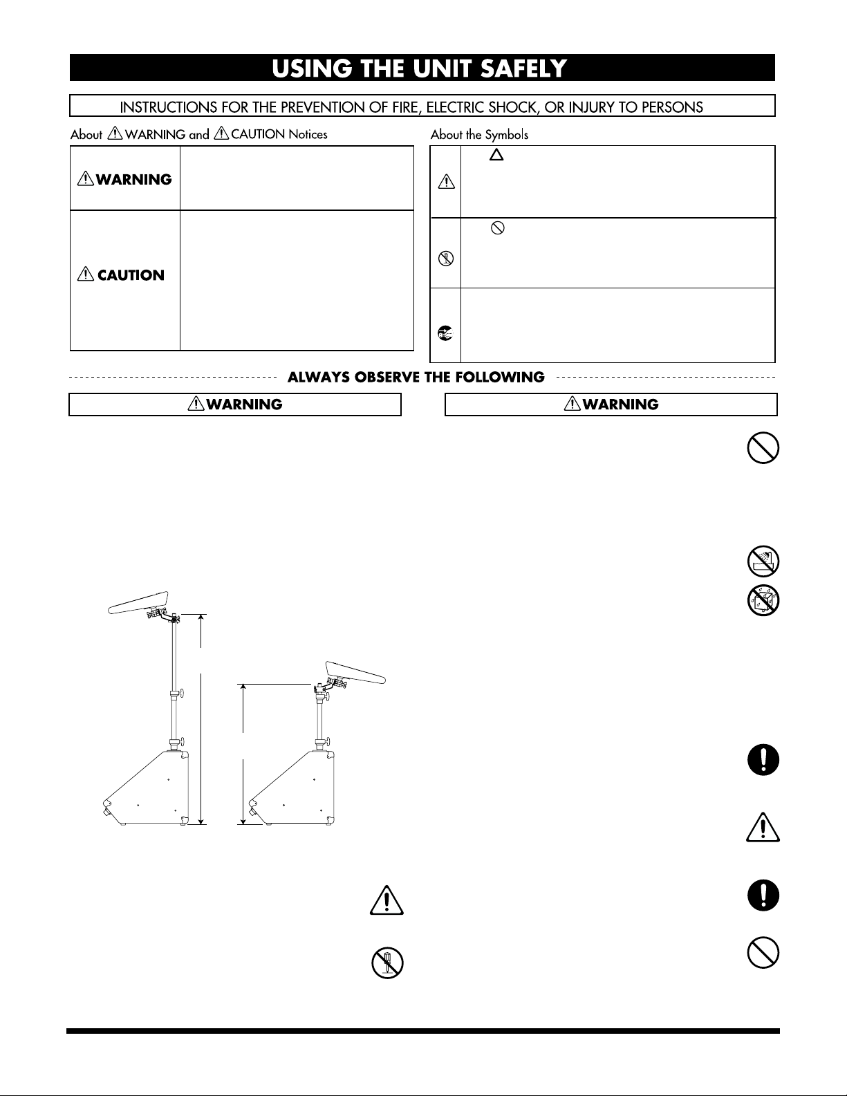
• The Pipe Stand of Model PM-1 is to be used with Roland’s
Models SPD-20or HPD-15 only. Use with other Models or
use without proper installation may result in instability
causing possible severe injury and/or property damage.
For proper installation:
A. Setup the SPD-20 or HPD-15 as per diagram A for
normal use.
B. In case of setting the SPD-20 or HPD-15 at the back of
the PM-1, keep the height of the stand to under 80 cm.
Use under
120 cm
Use under
80 cm
A. Normal Installation B. Reverse Installation
..........................................................................................................
001
• Before using this unit, make sure to read the
instructions below, and the Owner’s Manual.
..........................................................................................................
002a
• Do not open or perform any internal modifications on the unit.
..........................................................................................................
The symbol alerts the user to important instructions
or warnings.The specific meaning of the symbol is
determined by the design contained within the
triangle. In the case of the symbol at left, it is used for
general cautions, warnings, or alerts to danger.
The symbol alerts the user to items that must never
be carried out (are forbidden). The specific thing that
must not be done is indicated by the design contained
within the circle. In the case of the symbol at left, it
means that the unit must never be disassembled.
The ● symbol alerts the user to things that must be
carried out. The specific thing that must be done is
indicated by the design contained within the circle. In
the case of the symbol at left, it means that the powercord plug must be unplugged from the outlet.
003
• Do not attempt to repair the unit, or replace parts
within it (except when this manual provides
specific instructions directing you to do so). Refer
all servicing to your retailer, the nearest Roland
Service Center, or an authorized Roland
distributor, as listed on the “Information” page.
..........................................................................................................
004
• Never use or store the unit in places that are:
Subject to temperature extremes (e.g., direct
•
sunlight in an enclosed vehicle, near a heating
duct, on top of heat-generating equipment); or are
• Damp (e.g., baths, washrooms, on wet floors);
or are
• Humid; or are
• Exposed to rain; or are
• Dusty; or are
• Subject to high levels of vibration.
..........................................................................................................
007
• Make sure you always have the unit placed so it is
level and sure to remain stable. Never place it on
stands that could wobble, or on inclined surfaces.
..........................................................................................................
008a
• The unit should be connected to a power supply
only of the type described in the operating instructions, or as marked on the unit.
..........................................................................................................
008e
• Use only the attached power-supply cord.
..........................................................................................................
009
Do not excessively twist or bend the power cord,
•
nor place heavy objects on it. Doing so can damage
the cord, producing severed elements and short
circuits. Damaged cords are fire and shock hazards!
..........................................................................................................
3
Page 4
010
• This unit, either alone or in combination with an
amplifier and headphones or speakers, may be
capable of producing sound levels that could cause
permanent hearing loss. Do not operate for a long
period of time at a high volume level, or at a level
that is uncomfortable. If you experience any hearing
loss or ringing in the ears, you should immediately
stop using the unit, and consult an audiologist.
..........................................................................................................
011
• Do not allow any objects (e.g., flammable material,
coins, pins); or liquids of any kind (water, soft
drinks, etc.) to penetrate the unit.
016
• Before using the unit in a foreign country, consult
with your retailer, the nearest Roland Service
Center, or an authorized Roland distributor, as
listed on the “Information” page.
..........................................................................................................
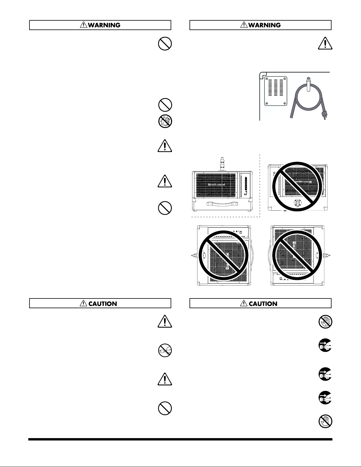
• When transporting
and storing the PM1, be sure to secure
the AC cord to the
cord hook on the
rear of the main unit.
..........................................................................................................
013
• In households with small children, an adult
should provide supervision until the child is
capable of following all the rules essential for the
safe operation of the unit.
..........................................................................................................
014
• Protect the unit from strong impact.
(Do not drop it!)
..........................................................................................................
015
• Do not force the unit’s power-supply cord to share
an outlet with an unreasonable number of other
devices. Be especially careful when using
extension cords—the total power used by all
devices you have connected to the extension
cord’s outlet must never exceed the power rating
(watts/amperes) for the extension cord. Excessive
loads can cause the insulation on the cord to heat
up and eventually melt through.
..........................................................................................................
..........................................................................................................
• When using the PM-1, set the unit up as shown in Figure
A. Do not use the unit with the arrangement in Figure B.
(fig. A) (fig. B)
101a
• The unit should be located so that its location or
position does not interfere with its proper ventilation.
..........................................................................................................
102a
• Always grasp only the plug on the power-supply
cord when plugging into, or unplugging from an
outlet.
..........................................................................................................
104
• Try to prevent cords and cables from becoming
entangled. Also, all cords and cables should be
placed so they are out of the reach of children.
..........................................................................................................
106
• Never climb on top of, nor place heavy objects on
the unit.
..........................................................................................................
4
107a
Never handle the power cord or its plug with wet hands
•
when plugging into, or unplugging from, an outlet.
..........................................................................................................
108a
• Before moving the unit, disconnect the power
plug from the outlet, and pull out all cords from
external devices.
..........................................................................................................
109a
• Before cleaning the unit, turn off the power and
unplug the power cord from the outlet.
..........................................................................................................
110a
•
Whenever you suspect the possibility of lightning in your
area, pull the plug on the power cord out of the outlet.
..........................................................................................................
119
• The rear panel of the main unit may become hot,
so take care to avoid burns.
..........................................................................................................
Page 5

IMPORTANT NOTES
291b
In addition to the items listed under “IMPORTANT SAFETY INSTRUCTIONS” and “USING THE UNIT SAFELY” on pages 2
and 3–4, please read and observe the following:
Power Supply
301
• Do not use this unit on the same power circuit with any
device that will generate line noise (such as an electric
motor or variable lighting system).
307
• Before connecting this unit to other devices, turn off the
power to all units. This will help prevent malfunctions
and/or damage to speakers or other devices.
Placement
351
• Using the unit near power amplifiers (or other equipment
containing large power transformers) may induce hum.
To alleviate the problem, change the orientation of this
unit; or move it farther away from the source of interference.
352a
• This device may interfere with radio and television
reception. Do not use this device in the vicinity of such
receivers.
352b
• Noise may be produced if wireless communications
devices, such as cell phones, are operated in the vicinity of
this unit. Such noise could occur when receiving or initiating a call, or while conversing. Should you experience
such problems, you should relocate such wireless devices
so they are at a greater distance from this unit, or switch
them off.
354b
• Do not expose the unit to direct sunlight, place it near
devices that radiate heat, leave it inside an enclosed
vehicle, or otherwise subject it to temperature extremes.
Also, do not allow lighting devices that normally are used
while their light source is very close to the unit (such as a
piano light), or powerful spotlights to shine upon the
same area of the unit for extended periods of time.
Excessive heat can deform or discolor the unit.
355
• To avoid possible breakdown, do not use the unit in a wet
area, such as an area exposed to rain or other moisture.
356
• Do not allow rubber, vinyl, or similar materials to remain
on the unit for long periods of time. Such objects can
discolor or otherwise harmfully affect the finish.
357
• Do not put anything that contains water (e.g., flower
vases) on the unit. Also, avoid the use of insecticides,
perfumes, alcohol, nail polish, spray cans, etc., near the
unit. Swiftly wipe away any liquid that spills on the unit
using a dry, soft cloth.
359
• Do not paste stickers, decals, or the like to this instrument.
Peeling such matter off the instrument may damage the
exterior finish.
Maintenance
401a+401b
• For everyday cleaning wipe the unit with a soft, dry cloth
or one that has been slightly dampened with water. To
remove stubborn dirt, use a cloth impregnated with a
mild, non-abrasive detergent. Afterwards, be sure to wipe
the unit thoroughly with a soft, dry cloth. Rubbing too
hard in the same area can damage the finish.
402
• Never use benzine, thinners, alcohol or solvents of any
kind, to avoid the possibility of discoloration and/or
deformation.
• For routine care of the carpeted surfaces, use a brush with
stiff bristles.
Additional Precautions
553
• Use a reasonable amount of care when using the unit’s
buttons, sliders, or other controls; and when using its jacks
and connectors. Rough handling can lead to malfunctions.
556
• When connecting / disconnecting all cables, grasp the
connector itself—never pull on the cable. This way you
will avoid causing shorts, or damage to the cable’s
internal elements.
557
• A small amount of heat will radiate from the unit during
normal operation.
558a
• To avoid disturbing your neighbors, try to keep the unit’s
volume at reasonable levels. You may prefer to use
headphones, so you do not need to be concerned about
those around you (especially when it is late at night).
559a
• When you need to transport the unit, package it in the box
(including padding) that it came in, if possible. Otherwise,
you will need to use equivalent packaging materials.
562
• Use a cable from Roland to make the connection. If using
some other make of connection cable, please note the
following precautions.
• Some connection cables contain resistors. Do not use
cables that incorporate resistors for connecting to this
unit. The use of such cables can cause the sound level
to be extremely low, or impossible to hear. For information on cable specifications, contact the manufacturer of the cable.
5
Page 6

Panel Descriptions
1
2
3
4
5
Front Panel
fig.20a
1.Volume Knob
These adjust the individual channel volume levels. The volume increases as the knobs are
turned further to the right (clockwise).
CH1
This accepts input levels ranging from mic input (-50 dBu) to line level from sound modules
and other equipment (-20 dBu).
CH2, CH3
These accept line level input from sound modules and other equipment (-20 dBu).
CH4 (Monitor Function)
This accepts line level input from sound modules and other equipment (-20 dBu).
Signals input to CH4 are output not to the LINE OUT jack (9), but directly to the PM-1’s
speakers or to headphones.
This is used for talkback from the main PA, or for other applications, such as when one performer
wants to monitor the click track while synchronizing the performance with a sequencer.
2.EQUALIZER Controls
The PM-1 is equipped with a two-band equalizer, making it possible for you to create a
variety of sounds.
BASS knob
This adjusts the volume of the bass.
TREBLE knob
This adjusts the volume of the treble.
3.MASTER Controls
These controls control the output of the built-in speaker and the PHONES jack.
VOLUME knob
This adjusts the volume.
PHONES (headphones) jack
Connect the headphones. No sound is output from the PM-1’s speakers when headphones
are connected.
* Always be sure to lower the MASTER VOLUME to zero whenever connecting and disconnecting
headphones.
* Although the PHONES jack accepts stereo plugs, the audio output is mono.
4.POWER Indicator
When the power is on, the pilot light will be lit.
5.POWER Switch
This switch turns the power on/off.
* Always be sure to lower the volume on the PM-1 and any connected equipment to zero whenever turning the power on or off.
* This unit is equipped with a protection circuit. A brief interval (a few seconds) after power up is required before the unit will operate
normally. Even with the volume all the way down, you may still hear some sound when the power is switched on, but this is normal, and
does not indicate a malfunction.
6
Page 7

Rear Panel
fig.20b
6.CH1 Input Jack
Accepts input levels ranging from mic input (-50 dBu) to line level (-20 dBu).
In addition to a 1/4" phone jack, this channel is also equipped with a balanced
XLR connector useful for connecting mics.
Use this for connecting mics, digital percussion, sound modules, and other input
devices.
7.CH2 and CH3 Input Jacks
These are 1/4" phone input jacks that accept line level input (-20 dBu).
Use for connecting digital percussion, sound modules, and other input devices.
8.CH4 Input Jack (Monitor Function)
This is a 1/4" phone input jack that accepts line level input (-20 dBu).
Use for connecting digital percussion, sound modules, and other input devices,
and for talkback from PAs.
Signals input here are output not to the LINE OUT jack (9), but directly to the PM1’s speakers or to headphones.
This is used for talkback from the main PA, or for other applications, such as when
one performer wants to monitor the click track while synchronizing the
performance with a sequencer.
Panel Descriptions
6
7
8
9
* When the LINE OUT jack (9) is not being used, this channel can be used in the same
manner as the other channels.
9.LINE OUT Jack
This output jack is connected to inputs that accept +4 dBu line level input.
Connect mixers, recorders, and other such equipment here.
* Signals input to the CH4 input jack (8) are not output here.
7
Page 8

Making Connections
fig.10
Mic
Percussion Pads
Output
Input
Mixer
* To prevent malfunction and/or damage to speakers or other
devices, always turn down the volume, and turn off the power
on all devices before making any connections. Set all of the PM1’s channel volume knobs as well as the MASTER VOLUME
knob to zero.
* The pin assignment for the XLR type connectors is as shown
below. Before making any connections, make sure that this pin
assignment is compatible with that of all your other devices.
fig.21
Output
Output
Drum Sound Module
Recorder
* Howling could be produced depending on the location of
microphones relative to speakers. This can be remedied by:
1. Changing the orientation of the microphone(s).
2. Relocating microphone(s) at a greater distance from
speakers.
3. Lowering volume levels.
Q: The volume level of the instrument connected to CH
1 – CH 4 are too low.
A: Could you be using a connection cable that contains a
resistor?
Use a connection cable that does not contain a resistor.
Stereo
Headphones
8
Page 9

Turning On and Off the Power
Making Connections
Once the connections have been completed, turn on power to
your various devices in the order specified. By turning on
devices in the wrong order, you risk causing malfunction
and/or damage to speakers and other devices.
* Before switching off the power, lower the volume on each of the
devices in your system and then TURN OFF the devices in the
reverse order to which they were switched on.
1.
Make sure that all volume controls on the PM-1 and
connected devices are set to 0.
2.
Turn on the all connected device(s).
3.
Turn on the PM-1.
4.
If a mixer is connected to the LINE OUT jack on the PM-1,
turn on the mixer.
5.
Adjust the volume levels for the devices.
* This unit is equipped with a protection circuit. A brief interval
(a few seconds) after power up is required before the unit will
operate normally. For protect from sudden big sound, always
make sure to have the volume level turned down before
switching on power. Even with the volume all the way down,
you may still hear some sound when the power is switched on,
but this is normal, and does not indicate a malfunction.
Connection Example with Volume Settings
Here is an example showing how the PM-1 is
connected as a stage monitor, making full use of the
PM-1’s mixer and monitor functions.
A mic is input to CH1, which accepts mic level input.
Connect an SPD-20 and drum sound module or other
sound-generating device to the CH2 and CH3 inputs.
Input to CH4 is the talkback from a mixer or other
input, disabling the output to LINE OUT.
Connecting as shown above results in a system that lets
you perform using multiple sound sources
simultaneously, while also allowing the talkback from
the PA to be heard only through the PM-1.
In order to get optimum sound from the PM-1 when
performing, set the volume as described below.
1.
Adjust the MASTER VOLUME knob until the
sound in each of the channels is clearly audible,
thereby allowing you to adjust the volume balance.
SPD-20
Output
CH2
CH4LINE OUT
Mic
CH1
CH3
Output
Drum Sound Module
2.
Adjust the individual channel volume knobs until
you obtain the proper volume balance throughout
the channels.
3.
Use the EQUALIZER to adjust the tone to your liking.
* If the sound at this point is distorted, lower the
individual channel volume knobs and/or the volume
knobs for devices connected to the input jacks.
4.
Adjust the MASTER VOLUME knob until the volume is at the right level.
Input
Mixer
Monitor
Out
Output
Power Amp
Main Speakers
9
Page 10

Proper use of the internal stand
●
To avoid the risk of the unit overturning, never use the internal stand for attaching anything other than the SPD-20 or the HPD-15.
●
When attaching the SPD-20 or the HPD-15 to the internal stand, you must use the APC-33 (an all purpose clamp set: sold separately).
Attaching the Stand and Adjusting the Stand Height
When shipped, the stand is detached from the main unit. To
prepare the stand for use, follow the procedure below to
attach the stand to the main unit.
fig.13
Pipe 2
Screw 2
Stand insertion hole
1.
Loosen attachment screw 1.
2.
Insert stand pipe 1 into the PM-1’s stand insertion hole,
then tighten attachment screw 1.
3.
Loosen attachment screw 2.
4.
Insert stand pipe 2 into the insertion hole in stand pipe 1,
then tighten attachment screw 2.
This completes setup of the stand.
Pipe 1
Screw 1
Adjust the height of the internal stand in the following way.
* Remove the SPD-20 or the HPD-15 from the stand before
adjusting if it is already attached.
1.
Loosen screw 1, and adjust the height of pipe 1.
2.
After deciding the height of pipe 1, fasten screw 1.
3.
While holding pipe 2 with your hand, loosen screw 2 and
adjust the height of pipe 2.
4.
After deciding the height of pipe 2, fasten screw 2.
5.
After deciding the total height of the internal stand, attach
the SPD-20 or the HPD-15 with the APC-33 already
attached.
To prevent the SPD-20 or the HPD-15 from falling while
in performance, make sure screw 1 and screw 2 are
fastened tightly.
fig.15a
With the APC-33, adjust
the angle at which the
SPD-20 or HPD-15 is
attached.
Loosen each screw and
adjust the angle. When
you have determined the
proper angles, tighten the
screws.
Before tightening the
screws, make sure that the
hardware portions that get tightened firmly grip the arm
section, and are prevented from slipping.
If the ridges and valleys are not properly meshed, the angle
may change during the performance, possibly resulting in
injury or damage to your equipment.
Vertical angle
adjustment screw
Lateral angle
adjustment screw
10
Page 11

●
If the SPD-20 or the HPD-15 is installed facing the front
side (fig. C), the height of the internal stand can be as
high as 120cm (maximum).
●
If the SPD-20 or the HPD-15 is installed other than the
front side (fig. D), the height of the internal stand must be
under 80cm.
●
When the PM-1 is moved or stored, please set the internal
stand shortest for safety purpose.
●
Use without proper installation may result in instability
causing possible severe injury and/or property damage.
fig.06
Proper use of the internal stand
When Attaching the SPD-20 or HPD-15 to the Stand
When attaching the SPD-20 or HPD-15 to the stand, use the
APC-33 to secure these pads to the stand.
Attaching APC-33 to SPD-20
1.
Using a 4 mm wrench, remove the four screws from the
bottom of the SPD-20.
fig.22
Use under
120 cm
Use under
80 cm
(fig. C) (fig. D)
2.
Use the four screws you removed in step 1 to attach the
stand holder to the bottom of the SPD-20.
fig.23
The screws included with the APC-33 cannot be used.
11
Page 12

Proper use of the internal stand
Attaching APC-33 to HPD-15
When attaching the APC-33 to the HPD-15, make sure to use
35mm screw supplied with the APC-33. Using other screws
may damage the unit.
fig.14
Wide
Narrow
Attaching the APC-33 to the
internal stand of PM-1
Attach the APC-33 to the internal stand in the following way.
1.
Clamp the bar of the stand with BLOCK A and BLOCK B.
2.
Fasten SCREW C slightly loose. The bar should be
clamped at the V-shape of BLOCK A and BLOCK B.
3.
Fasten SCREW D tightly. Adjust SCREW C and SCREW
D so that BLOCK A and BLOCK B are in parallel.
4.
After attaching to the stand, slightly shake the APD-20 or
HPD-15 to make sure it doesn’t loosen.
To prevent the unit from falling during performance, make
sure the bar of the stand is clamped at the V-shape of BLOCK
A and BLOCK B, and fasten SCREW C and SCREW D
tightly.
fig.15
BLOCK A
SCREW C
SCREW D
Make sure the point on the stand where the APC-33 is
attached is sufficiently clear of the end of the stand.
BLOCK B
STAND
12
Page 13

Specifications
PM-1: PERSONAL MONITOR AMPLIFIER
Rated Power Output
60 W
Nominal Input Level (@1 kHz)
INPUT
Channel 1 (MIC/LINE) -50 dBu to -20 dBu
Channel 2,3 (LINE) -20 dBu
Channel 4 (MONITOR) -20 dBu
Nominal Output Level (@1 kHz)
LINE OUT + 4 dBu
* 0 dBu = 0.775 Vrms
Speakers
30 cm (12 inches) x1
Tweeter x1
Controls
Channel 1 (MIC/LINE) Volume Knob
Channel 2 (LINE) Volume Knob
Channel 3 (LINE) Volume Knob
Channel 4 (MONITOR) Volume Knob
Equalizer
BASS Knob
TREBLE Knob
MASTER VOLUME Knob
POWER Switch
Indicator
POWER
Connectors
Channel 1 Input Jack
Channel 2 Input Jack (1/4" Phone Type)
Channel 3 Input Jack (1/4" Phone Type)
Channel 4 Input Jack (1/4" Phone Type)
LINE OUT Jack (1/4" Phone Type)
PHONES Jack
(XLR Type Balanced, 1/4" Phone Type)
(Stereo 1/4" Phone
Type
, Mono signal output)
Power Supply
AC 117 V, AC 230 V, AC 240 V
Power Consumption
52 W
Dimensions
630 (W) x 490 (D) x 565 (H) mm
24-13/16 (W) x 19-5/16 (D) x 22-1/4 (H) inches
(case of internal stand set minimum)
630 (W) x 490 (D) x 1200 (H) mm
24-13/16 (W) x 19-5/16 (D) x 47-1/4 (H) inches
(case of internal stand set maximum)
Weight
22 kg
48 lbs 9 oz
Accessory
Owner’s Manual
Option
All Purpose Clamp Set: APC-33
* When performing on digital percussion attached to the PM-1’s
integrated stand, be sure to use only the APC-33 all purpose
clamp set to attach the device to the stand.
* In the interest of product improvement, the specifications and/
or appearance of this unit are subject to change without prior
notice.
13
Page 14

Memo...
Page 15

Memo...
For EU Countries
This product complies with the requirements of European Directives EMC 89/336/EEC and LVD 73/23/EEC.
Page 16

xxxxxxxx ’00-xx-xx-xxx
 Loading...