

Page 1
●
©
Version 2.0
Owner’s Manual
This manual explains how to use an MV-8000 in which “System Program Version 2.00”
(included with the MV8-VGA) is installed.
The main contents of this manual are:
• Items shown in the external display
• Operations using the mouse
• New functionality and changes added to the MV-8000 owner's manual
Please read this manual in conjunction with the original MV-8000 owner's manual.
About the Symbols and icons in this manual
• Text in square brackets [ ] refers to buttons on the panel of the MV-8000.
Buttons indicated as [F1 (Sample)] refer to the F1 (function 1) button when the F1 function
shown in the LCD is “Sample.”
• Where a range of values is shown, the default value is printed in bold type.
For example, an indication of
Range: 60 , 67, 72, 75 (Hz)
means that 60 Hz is the default value.
Indicates information that you should be aware of when using the MV-8000.
Indicates a convenient operation or useful music production technique.
Indicates supplementary information about an operation.
Indicates a reference page.
Indicates an explanation of a term.
Indicates operation from the MV-8000’s top panel.
Indicates operation from the Mouse and the external VGA display.
• Before using this unit, carefully read the sections entitled: “IMPORTANT SAFETY
INSTRUCTIONS” (Owner’s Manual p. 2), “USING THE UNIT SAFELY” (Owner’s Manual p. 3),
and “IMPORTANT NOTES” (Owner’s Manual p. 5). These sections provide important information
concerning the proper operation of the unit. Additionally, in order to feel assured that you have
gained a good grasp of every feature provided by your new unit, Quick Start and Owner’s Manual
should be read in its entirety. The manual should be saved and kept on hand as a convenient
reference.
• The explanations in this manual include illustrations that depict what should typically
be shown by the display. Note, however, that your unit may incorporate a newer,
enhanced version of the system (e.g., includes newer sounds), so what you actually see
in the display may not always match what appears in the manual.
2004 Roland Corporation
All rights reserved. No part of this publication may be reproduced in any form without the
written permission of ROLAND CORPORATION.
Roland Web Site http://www.roland.co.jp/
Page 2

Contents
Using an external display and mouse to operate the MV-8000 ..........4
The newly added VGA/MOUSE screen................................................................................................. 4
Using the two operating modes, the display, and the mouse.............................................................. 5
Switching between the two operating modes............................................................................. 5
Mouse........................................................................................................................................................... 6
About the mouse ............................................................................................................................. 6
Basic operation ................................................................................................................................ 6
Mouse operations............................................................................................................................ 8
Screen Section............................................................................................................................................ 10
SEQUENCE screen........................................................................................................................ 10
Operation section...................................................................................................................................... 22
Quick Tour .....................................................................................................................................22
Using the mouse to edit sequence data...................................................................................... 25
Using the mouse to edit a MIDI track (PIANO ROLL EDIT screen)..................................... 26
Step Recording............................................................................................................................... 28
Changes in Sampling and Importing ..................................................29
Sampling .................................................................................................................................................... 29
Importing................................................................................................................................................... 32
Importing the WAV or AIFF files ............................................................................................... 32
Importing the Standard MIDI Files ............................................................................................ 37
Importing from various CD-ROM libraries ..............................................................................38
Check multiple samples you have captured............................................................................. 40
Quick Assign ............................................................................................................................................. 41
Assigning a sampled sound a patch (partial) ........................................................................... 41
Assigning a sampled sound an audio phrase ........................................................................... 41
Assigning a patch (partial) by chopping a sample................................................................... 42
Assign multiple samples as partials........................................................................................... 43
Assign multiple samples as audio phrases ............................................................................... 44
Changes in Sample Edit .......................................................................45
Truncating ................................................................................................................................................. 45
Truncating a sample used by a partial’s SMT........................................................................... 45
Truncating a sample used by an audio phrase......................................................................... 46
Added the AUDIO PHRASE SAMPLE EDIT screen ..........................................................................49
Deleting the sample along with the partial (Delete Partial)............................................................... 50
Deleting the sample along with the audio phrase (Delete Audio Phrase)....................................... 51
Deleting the sample along with the patch (Delete Patch) .................................................................. 52
Assigning a partial to pads in a pitched scale (Set Chromatic) .........................................................53
Changes in recording and editing sequences ...................................55
Selecting a region quickly (Quick Region)............................................................................................ 55
The selected region in the SEQUENCE EDIT screen............................................................... 55
the selected region in the PIANO ROLL EDIT screen............................................................. 55
Initiate recording when a note message is received............................................................................ 56
Step-recording for the length of an audio phrase................................................................................56
Combining multiple MIDI tracks into one (Merge Tracks)................................................................ 57
Extracting specific note events (Split Notes) ........................................................................................ 58
Inserting blank measures at the specified time (Insert Measure)...................................................... 60
Using shortcuts to execute editing commands ....................................................................................61
Using shortcuts to switch the step time ................................................................................................61
Changes in Mixdown and Mastering...................................................62
Mixdown.................................................................................................................................................... 62
Mastering................................................................................................................................................... 63
2
Page 3

Using the MV-8000 with external devices...........................................65
Using the MV-8000 in Multitimbre Sampler Mode............................................................................. 65
Playing the MV-8000 from an externally-connected sequencer............................................. 65
Recording your velocity pad performance on an externally-connected sequencer .......................66
Synchronized operation with external devices (Slave)....................................................................... 69
Additional parameters in the SYNC screen .............................................................................. 69
Added the R-BUS screen.............................................................................................................. 70
Receive and synchronize to MIDI Clock ................................................................................... 71
Receive and synchronize to MTC ............................................................................................... 72
Use the MIDI IN connector of the DIF-AT24 .......................................................................................73
Changes in the others ..........................................................................74
Directly selecting a pad bank ([PAD BANKS]+Pad 1–16).................................................................. 74
Using the velocity pads to switch Track Mute and Solo .................................................................... 74
Starting a new song with your favorite settings (User Track Template) ......................................... 75
Saving a User Track Template..................................................................................................... 75
Using a user track template to create a song............................................................................. 76
Saving a song in SMF format (Save As SMF) .......................................................................................76
Note regarding saving to SMF ....................................................................................................77
Viewing the PATCH LIBRARY popup in the INSTRUMENTS screen............................................ 77
Copy or move entire folders ................................................................................................................... 77
Changes in MIDI Filter parameter......................................................................................................... 78
Changes in GLOBAL screen ...................................................................................................................78
Prevent the hard disk from being formatted (HD Format Protect parameter).................... 78
Adjusting the volume of the entire sampler ............................................................................. 78
Memo......................................................................................................79
3
Page 4
1.
2.
3.
Using an external display and mouse to operate the MV-8000
If the MV8-VGA is installed in the MV-8000, you can connect an external display
(VGA) and the included mouse, and perform operations from the external display.
Even when you are using an external display to operate the MV-8000, you can also
view information on the MV-8000’s built-in LCD screen.
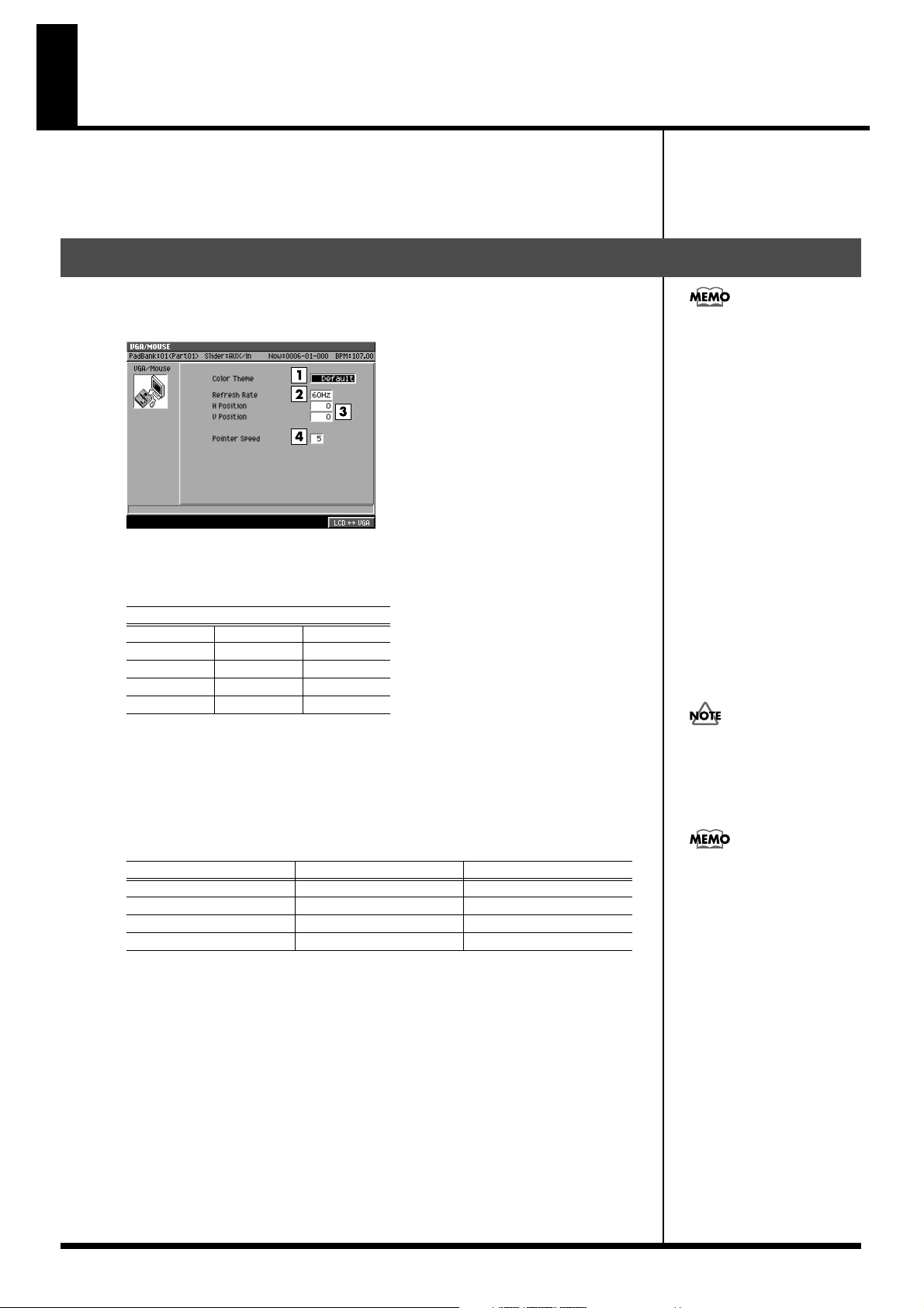
The newly added VGA/MOUSE screen
This screen lets you make settings for the external display and mouse if the MV8-VGA
(sold separately) is installed.
fig.vga-mouse-screen
In order to operate the MV-
8000 using an external display,
the MV-8000’s system program
version must be 2.00 or higher.
Color Theme
You can select the combination of colors used in the external display. Select your
favorite color scheme from the following choices.
Range
Default
Mint Slate Moss Green
Purple Orchid Copper
Grass Tan
Violet Gray
Refresh Rate
Sets the rate at which the monitor re-draws it image.
Range: 60 , 67, 72, 75 (Hz)
H Position and V Position
Adjust the H Position (Horizontal Position) and the V Position (Vertical Position)
parameters if you’d like to shift the image on your VGA monitor.
Refresh Rate
60
67 -5– 0 –5 -21– 0 –22
72 -5– 0 –5 -18– 0 –19
75 -5– 0 –5 -8– 0 –9
4.
Pointer Speed
Sets how fast the mouse’s cursor moves.
Range: 1 (Slow)–5–9 (Quick)
Chocolate
Magenta
H Position V Position
-3– 0 –4 -14– 0 –14
If you select a value the
monitor doesn’t support,
image quality may be poor,
and damage to the monitor
may result.
Depending on the H Position
or V Position settings, the
image shown in the external
display may be distorted. If the
external display you're using
has settings for adjusting the
image position, make
adjustments first on the
external display.
4
Page 5
●
●
Using an external display and mouse to operate the MV-8000
Using the two operating modes, the display, and the mouse
Here’s how to tell whether the current screen for operations is the external display or
the built-in LCD.
When the external display shows the “MV-8000 logo”
In this state you use the MV-8000’s panel and its own built-in LCD to perform
operations. The external display and mouse cannot be used for operations.
When the MV-8000’s LCD indicates “VGA MODE”
A 640 x 480 pixel color screen will appear on the external display, and you can operate
the MV-8000 from the external display (VGA mode). You can use the front panel to
perform the same operations as before, and also operate the MV-8000 using the
included mouse. The MV-8000’s LCD will indicate the status of the tracks and the
samples assigned to the velocity pads.
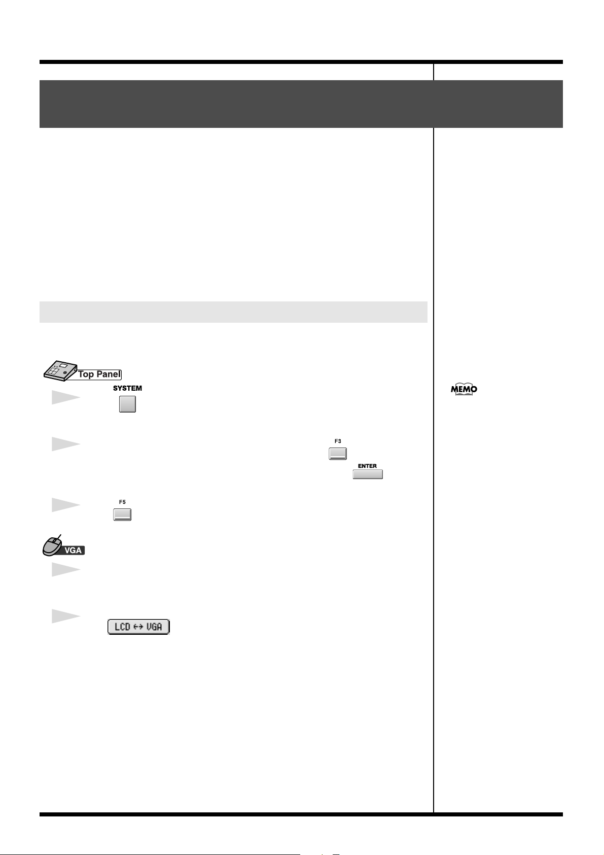
Switching between the two operating modes
Here’s how to select either the external display or the built-in LCD as the screen in
which you will operate the MV-8000.
1
Press
The SYSTEM MENU screen will appear.
2
With the cursor located in the lower row of icons, press (VGA/Mouse).
Alternatively, you can select the VGA/MOUSE icon and press .
The VGA/MOUSE screen will appear.
3
Press (VGA-LCD).
1
From the menu bar, click “SYSTEM” ➔ “VGA/Mouse.”
The VGA/MOUSE screen will appear.
You can press the [SHIFT] +
[EXIT] buttons to switch the
operating mode from the
external display to the internal
LCD. You can’t use this
method to switch from the
internal LCD to the external
display.
2
Click .
You will be able to operate in the built-in LCD.
5
Page 6
j
b
●
●
●
●
Using an external display and mouse to operate the MV-8000
Mouse
You can use the included mouse to operate the on-screen knobs and buttons, or the
sequence data in the play list.
When you move the mouse, the mouse pointer (the arrow symbol) will move in the
screen. By placing the mouse pointer on a button or knob and pressing (clicking) the
mouse button you can perform various operations depending on the selected item.
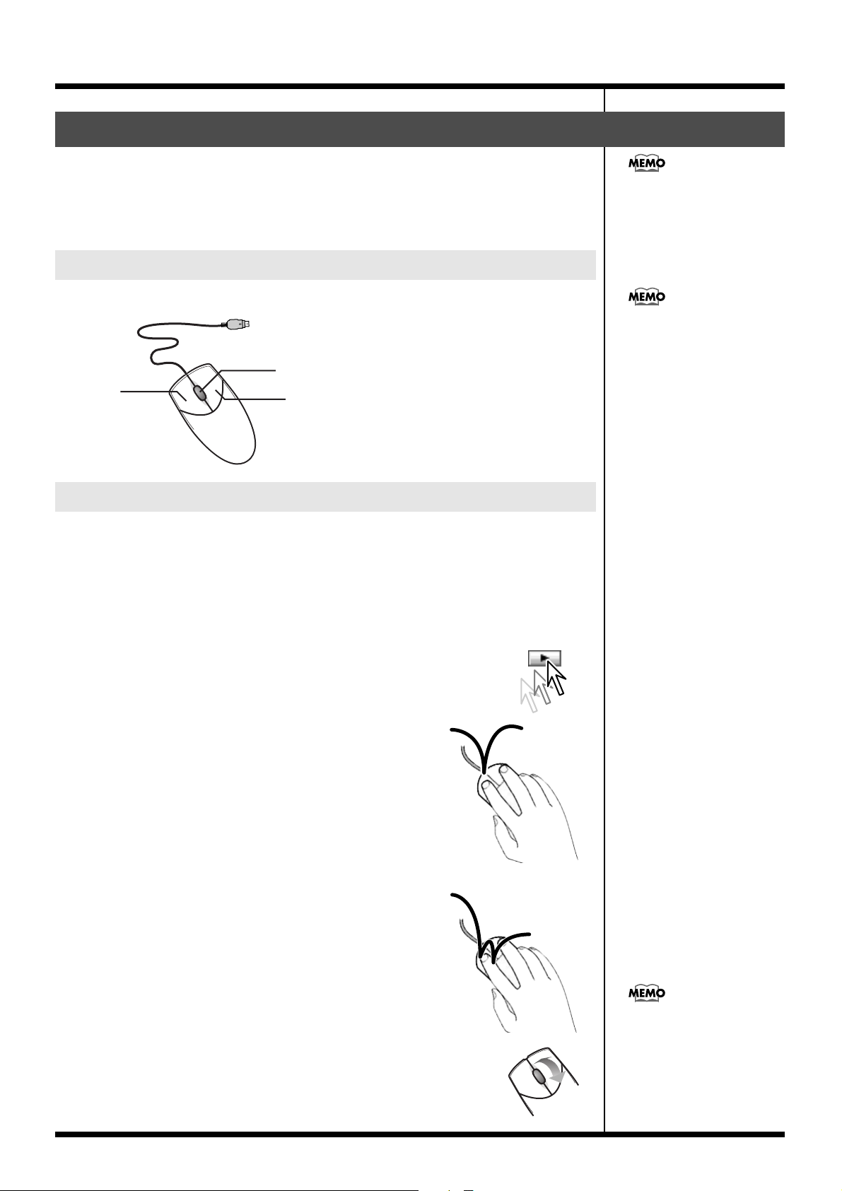
About the mouse
The included mouse is a wheel mouse.
Wheel
Left-button
Right-button
In order to use the mouse, the
MV-8000’s system program
must be version 2.00 or higher.
Mouse operations can be used
only in the external display.
The included mouse is an
optical mouse. It may not
function correctly on some
surfaces, so be sure to use it on
the included mouse pad.
Basic operation
Basic mouse operations are:
• Use the mouse pointer to indicate a button or knob in the screen (“point”)
• Press the mouse button (“click”)
• Turn the mouse wheel
Point
Move the tip of the mouse pointer to a button or knob shown in the
screen. This is called “pointing” at the button or knob.
Click
Point to a button or knob in the screen; then press and
release the mouse button once.
In some cases you will be specifically told to “right-click,”
which means to click using the right mouse button.
Double-click
Point to an on-screen button or knob, and rapidly press
the mouse button twice.
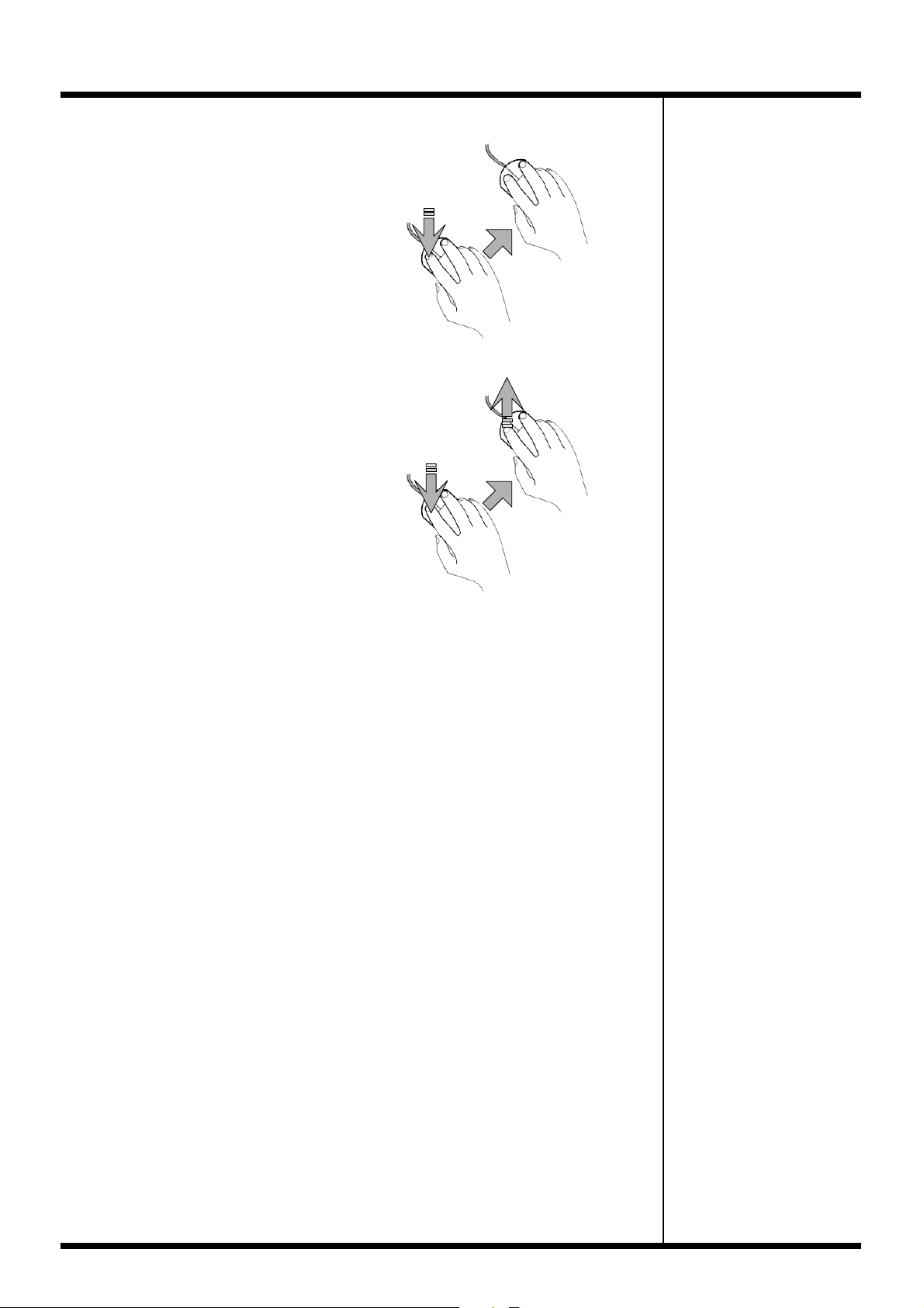
The wheel can also be clicked
Operating the wheel
Turn the wheel toward or away from yourself.
After clicking on a numerical parameter, you can turn the wheel to
raise or lower the value. The wheel can be used only for numerical
parameters; it cannot be used to operate buttons or knobs.
ust like the left or right
uttons, but the MV-8000 does
not use this action.
6
Page 7
Using an external display and mouse to operate the MV-8000
Drag
Move the mouse while holding down the
mouse button.
For example by dragging an event shown
in a play list, you can change the starting
time or the track of that event. By dragging
a knob you can change its setting.
Drag&Drop
●
●
1
Press
2
Move while holding down
Drag, and then release the mouse button at
the desired location.
The sequence data or knob you dragged
will move to the position at which you
released the button.
3
Release your finger
from the button
1
Press
2
Move while holding down
7
Page 8
Using an external display and mouse to operate the MV-8000
Mouse operations
Here’s how to operate the buttons and knobs shown in the screen.
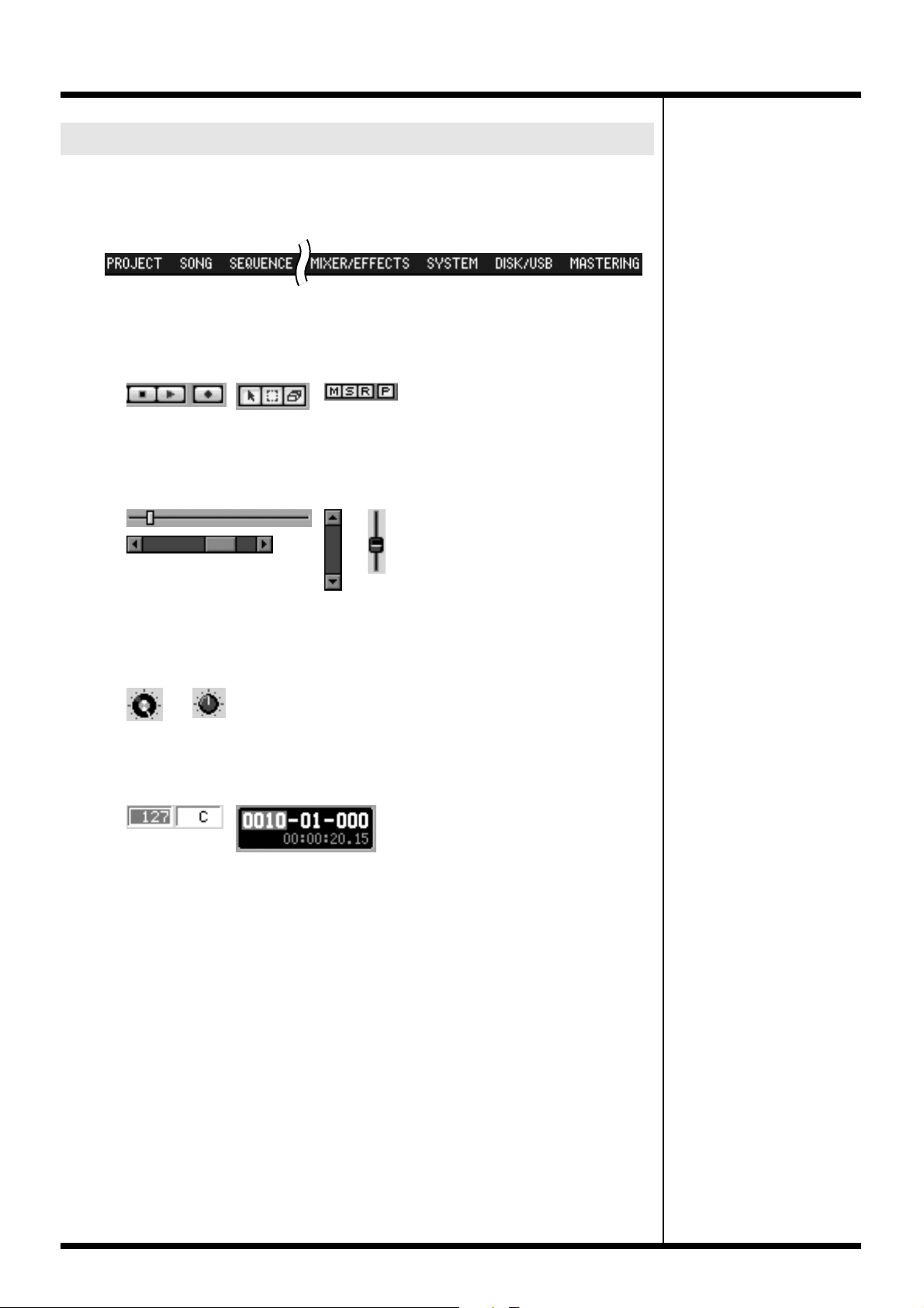
Menu Bar
Click an item in the menu bar, and a list showing the contents of that item will appear.
In the list, click the desired item.
Buttons
You can click on “buttons” shown in the screen to execute various operations or to
select parameters.
●
●
●
●
●
Sliders
Sliders are used to continuously vary a value. Point to the knob of a slider, and drag it
up or down.
Knobs
Knobs are used to continuously vary a value. Point to a knob, and drag it horizontally.
Numerical boxes
Numerical boxes are used to make detailed changes in the value of a parameter. Click
a numerical value to highlight it, and turn the wheel forward or backward to change
the value.
8
Page 9
Using an external display and mouse to operate the MV-8000
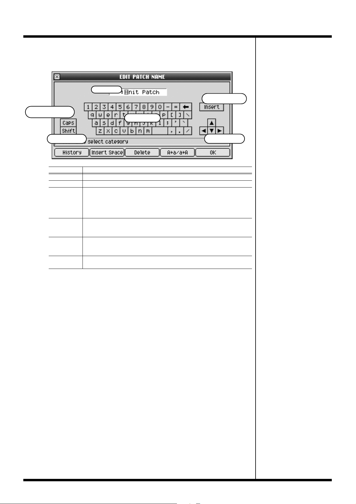
Name editor
This is a popup window used to input names in various screens. Input the desired
name by using the mouse to click the buttons.
Name
Insert button
●
Capital Lock button
Shift button
Name
Keyboard Use these buttons to select the characters you want to input.
Insert
button
Capital Lock
button
Shift button
Cursor
button
Keyboard
Cursor button
Explanation
This is the area in which you will input the name.
This button switches between Insert input mode and Overwrite input mode.
Insert input mode is selected when the button is in the inward position; the
characters you select will be input at the cursor position, and any subsequent
characters will be moved toward the right. In Overwrite input mode, any
previously-input characters will be overwritten by the characters you input.
This button switches between uppercase (Caps) and lowercase characters.
Uppercase (Caps) input is selected when the button is in the inward position;
only uppercase characters will be input from the keyboard.
This button temporarily switches the type of characters that will be input
from the keyboard. Clicking the keyboard when the Shift button is in the
inward position will defeat the Shift button.
These buttons change the position at which characters from the keyboard will
be input.
9
Page 10
Screen Section
Screen Section
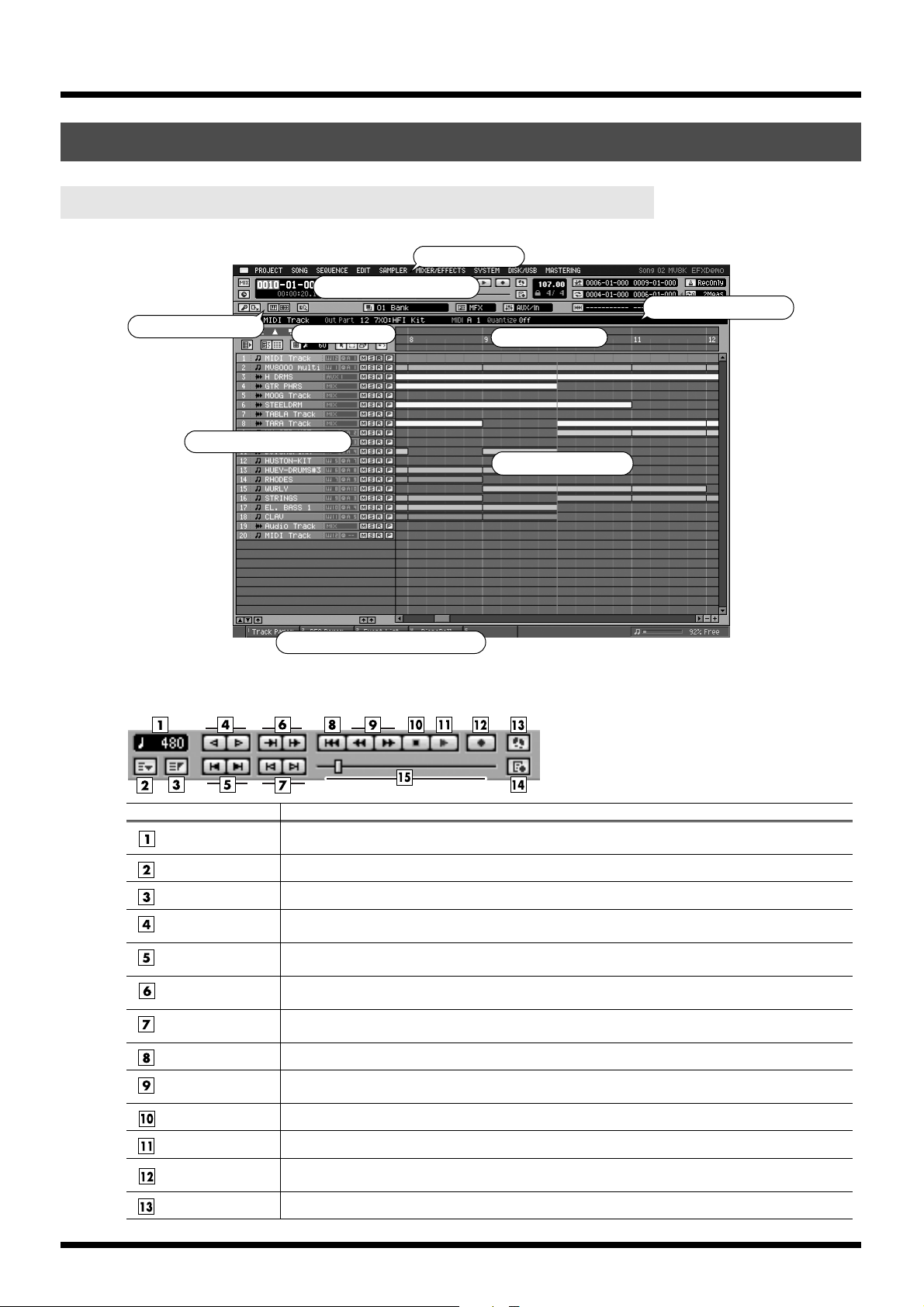
SEQUENCE screen
Launcher Block
Tr acklist Area
Tr ansport Block
Tools Area
Menu Bar
Ruler Area
Playlist Area
Inspector Area
●
Transport Block
fig.transport-block1
Step Time
Marker button
Locator button
Step button
(Rewind/Forward)
Marker button
(Previous/Next)
Preview button
(To/From)
Event button
(Previous/Next)
Top button
Meas button
(Rewind/Forward)
Stop button
Play button
REC button
Step REC button
Function Button Block
Explanation
This indicates the range of movement that will occur when you press the step buttons (Rewind/Forward). You can click this area to see a list of the available movement ranges.
The MARKER popup will appear.
The LOCATOR popup will appear.
These buttons return or advance the current time location by the range specified in Step Time.
These buttons move the current time location to the next or previous recorded marker.
These buttons audition a several-second portion (specified by Preview Length) before or after the current time location.
These buttons move the current time location to the next or previous recorded event.
Return to the start of the current song (0001-01-000).
These buttons move the current time location forward or backward in one-measure steps.
To stop the sequencer.
To play the sequencer.
The RECORD PARAMETER popup will appear. Here you can make preparations for recording data
into the sequencer.
The STEP REC popup will appear. Starts the step recording.
10
Page 11
REC Parameter
button
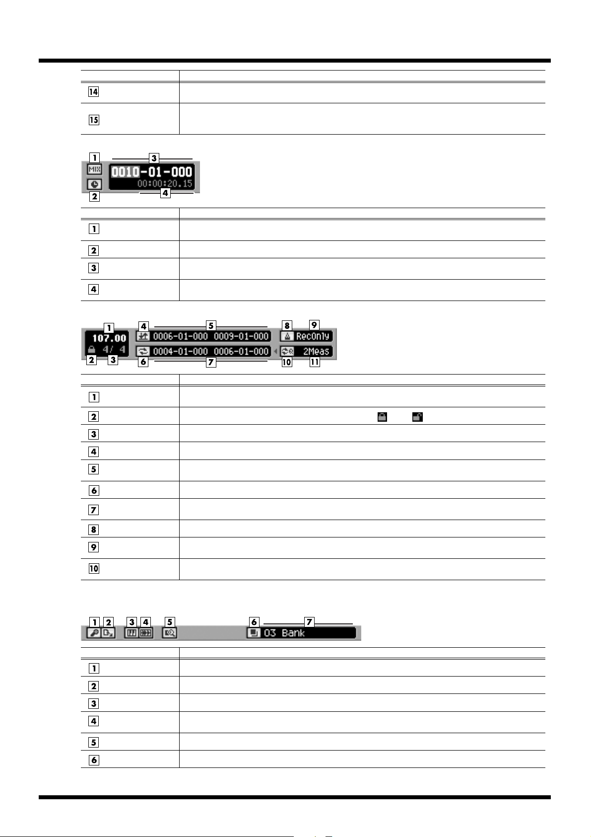
Song Position Bar
fig.transport-block2
Mixdown Mode
button
Sync Mode button
Current Time
Location
Current Time
Location
Explanation
The RECORD PARAMETER popup will appear.
The entire length of this bar corresponds to the length of the current song, and the scrollbar handle
indicates the current time location. You can move the current time location by dragging or clicking the
scrollbar handle.
Explanation
This switches the mixdown mode. If you record while this is on, the current song will be mixed down.
Here you can switch the synchronization mode.
This area indicates the current time location in “measures - beats - ticks.” You can click a numerical
field and change the time.
This area indicates the current time location in “hours : minutes : seconds . frames.”
●
fig.transport-block3
BPM (Tempo)
Tempo Track Switch
Time Signature
Auto Punch button
Auto Punch
In/Out
Loop button
Loop Start/End
Metronome Mode
Loop Quick Set
button
Loop Quick Set
Length
Launcher Block
fig.launcher-block1
Explanation
This indicates the tempo at the current time location. If the tempo track is off, you can click this value
and change the tempo.
You can click this area to switch the Tempo Track On ( )/Off ( ).
Display the time signature of the current song.
This button switch the Auto Punch function On/Off.
This area indicates the auto punch-in time (at left) and auto punch-out time (at right). You can click a
numerical field and change the time.
This button switch the Loop function On/Off.
This area indicates the loop-start time (at left) and loop-end time (at right). You can click a numerical
field and change the time.
Specifies when the metronome signal will be output.
This button makes the playback loop from the beginning of the current beat for the length specified
by the Loop Quick Set Length setting.
This indicates the loop length that will be used when you press the Loop Quick Set button. You can
click this to see a list of the available loop lengths.
Sampling button
Import button
Instruments button
Audio Phrases
button
Quick Edit button
Pad Banks button
Explanation
The SAMPLING popup will appear. Here you can make settings and execute sampling.
The IMPORT popup will appear. Here you can import data from the hard disk or a CD.
The INSTRUMENTS popup will appear. Here you can edit or make settings for instruments.
The AUDIO PHRASES popup will appear. Here you can edit or make settings for audio phrases.
Here you can edit the audio phrases or the partials of the current track.
The PAD BANKS popup will appear. Here you can switch the pad bank of the velocity pads.
11
Page 12
Pad Bank
Number/Name
fig.launcher-block2
Effects button
Effect Section
Selector
Mixer button
Mixer Section
Selector
Region In/Out
button
Region In/Out point
Explanation
Display the current pad bank and pad name. If the tempo track is off, you can click this value and
change the tempo.
Explanation
The EFFECTS popup will appear. Here you can make settings for the built-in MFX, Delay/Chorus and
Reverb.
This selects the effect module (MFX, delay/chorus, reverb) that will be controlled by the C1–C3 knobs.
The MIXER popup will appear. Here you can adjust the volume and panning of the audio tracks and
instrument parts.
This displays mixer sections which can be controlled by the eight sliders on the MV-8000’s panel. A
list of the available mixer sections will appear when you click this.
The available mixer sections are:
• Audio Track 1–8
• Instrument Part 1–8
• Instrument Part 9–16
• AUX1–4/Effect Return/Audio Phrase/Input
• Assignable sliders
This button specifies the current time location as region-in (beginning of the selected region) or regionout (end of the selected region).
This area indicates the region-in time (at left) and region-out time (at right). You can click a numerical
field and change the time.
●
Playlist Block
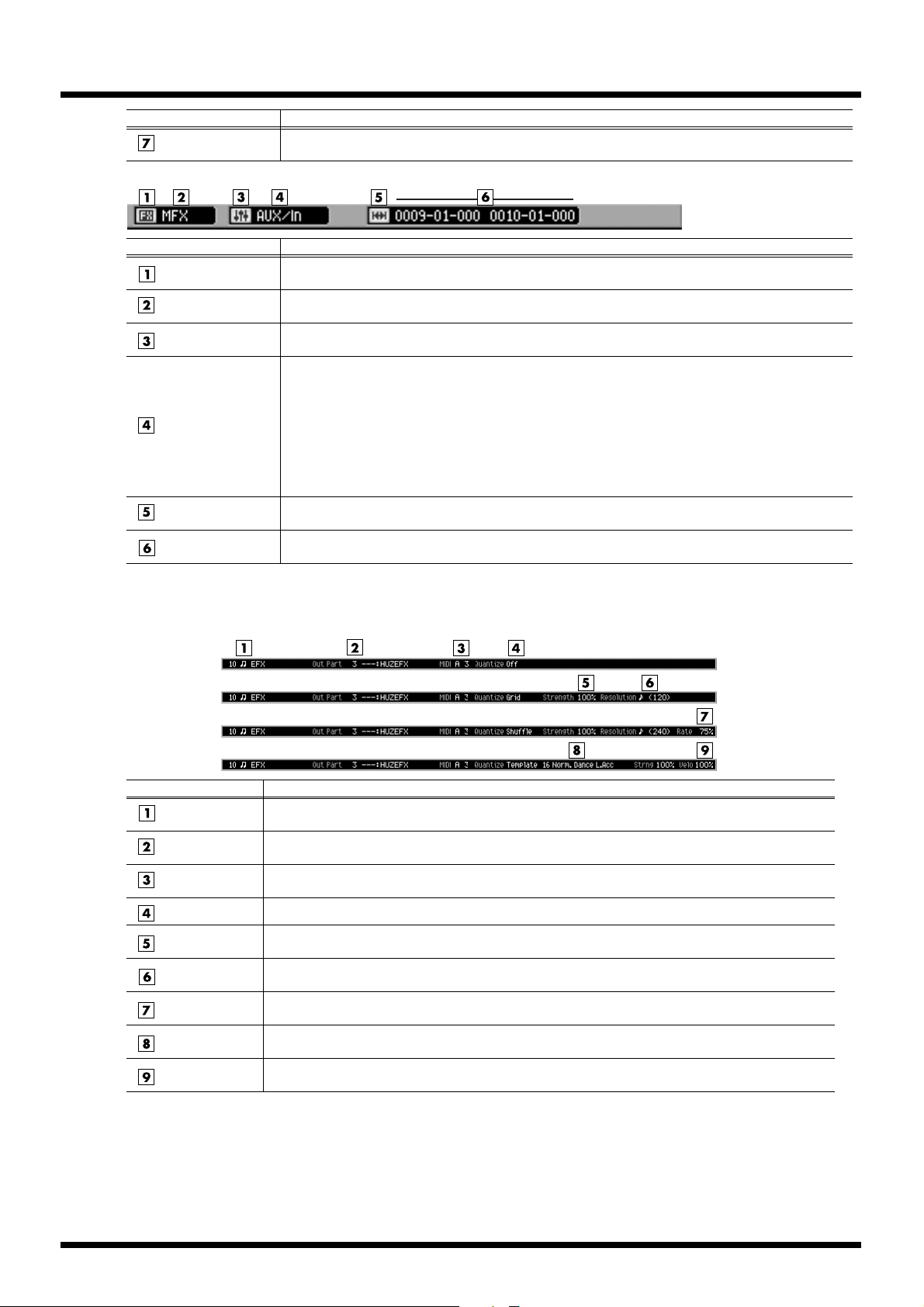
Inspector Area (When the current track is MIDI track)
Quantize Type=
Off
Grid
Shuffle
Template
Explanation
Current Track
Number/Name
Output Assign
(Instrument)
Output Assign
(MIDI)
Quantize Type
Strength
Resolution
Rate
Template
Velocity
Display the current track number and current track name.
This indicates the instrument part played by the current track. If you click this area, show the list of
the instrument part.
Specifies the MIDI connector and channel used for MIDI output of the data from the MIDI track.
Display the setting of quantization of the current track.
Display the strength of quantization. You can click the numerical value to edit the strength. (This is
displayed when the Quantize Type is set to Grid or Shuffle.)
Display the quantization timing. You can click the numerical value to edit the resolution. (This is
displayed when the Quantize Type is set to Grid or Shuffle.)
This indicates the amount of “swing” that will be applied when the Quantize Type is set to Shuffle.
You can click the numerical value to edit the rate.
This indicates the template name that will be applied when the Quantize Type is set to Template. You
can click the template name to show the template list and select the other template.
This indicates the strength of the velocity correction that will be applied when the Quantize Type is
set to Template. You can click the numerical value to edit the velocity.
12
Page 13
Inspector Area (When the current track is Audio Track)
Explanation
Current Track Number/Name
Output Assign
Display the current track number and current track name.
Specifies the output connector from which the audio recorded on the track will be output.
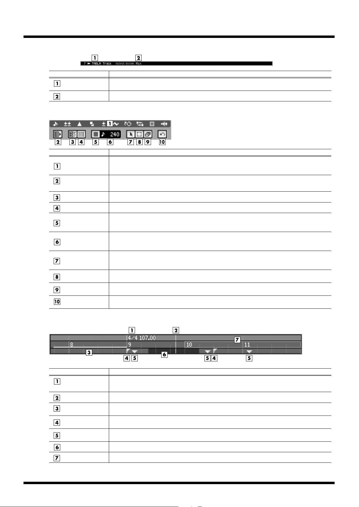
Tools Area
Explanation
This indicates the type of events that will be displayed in the SEQUENCE screen or in the EVENT LIST
View Filter
popup window. By clicking an icon you can specify whether that type of event will be displayed
(white) or will be hidden (black).
Expand Track List
Area button
Piano Roll button
Event List button
Snap button
Grid Resolution
Arrow button
Range button
Eraser button
Undo/Redo
button
Ruler Area
fig.ruler-
This expands the track list area display.
The PIANO ROLL EDIT popup will appear. This is available when the current track is a MIDI track.
The EVENT LIST popup will appear. This is available when the current track is a MIDI track.
If this is on, clicking in the play list or ruler will automatically select a suitable location (such as the
beginning of a measure). Since the interval of this division is specified by the Grid Resolution setting,
you can use this feature to “snap” your selection to precise units of beats or measures.
This indicates the unit (the level of detail) that can be selected with the mouse pointer when using the
Snap function. By clicking the numerical value you can specify whether that list of resolution will be
displayed.
This switches the mouse pointer to Arrow mode. Use this when you want to select a range of events
in the play list. All events included in the mouse selection will be selected even if they extend beyond
the range.
This switches the mouse pointer to Range mode. Use this when you want to select a range of events
in the play list. The range selected by the mouse will be the actual selected range.
This switches the mouse pointer to Eraser mode. In Eraser mode, you can click an event in the play list
to delete it.
You can click this button to cancel (UNDO) the results of an editing command in sequencer section. If
you then click the button again, you can cancel the UNDO (i.e., REDO).
Tempo Change
Event
Current Time
Region of Auto
Punch In/Out
Locator
Marker
Selected Region
Region of Loop
Explanation
This indicates the location of a change in tempo and time signature.
The current time is indicated by a red line.
This indicates the region (red) in which Record mode will be enabled automatically.
These are locators placed in the song. You can place up to 10 locators in a song. The desired time
location can be stored in any Locator number.
These are markers placed in the song. You can place up to 99 markers in a song. Markers are
automatically numbered in ascending order according to their time location.
This indicates the region of time you selected by dragging the mouse, etc.
The enclosed region (blue) will loop.
13
Page 14
Right-click on the Ruler Area
fig.ruler-area2
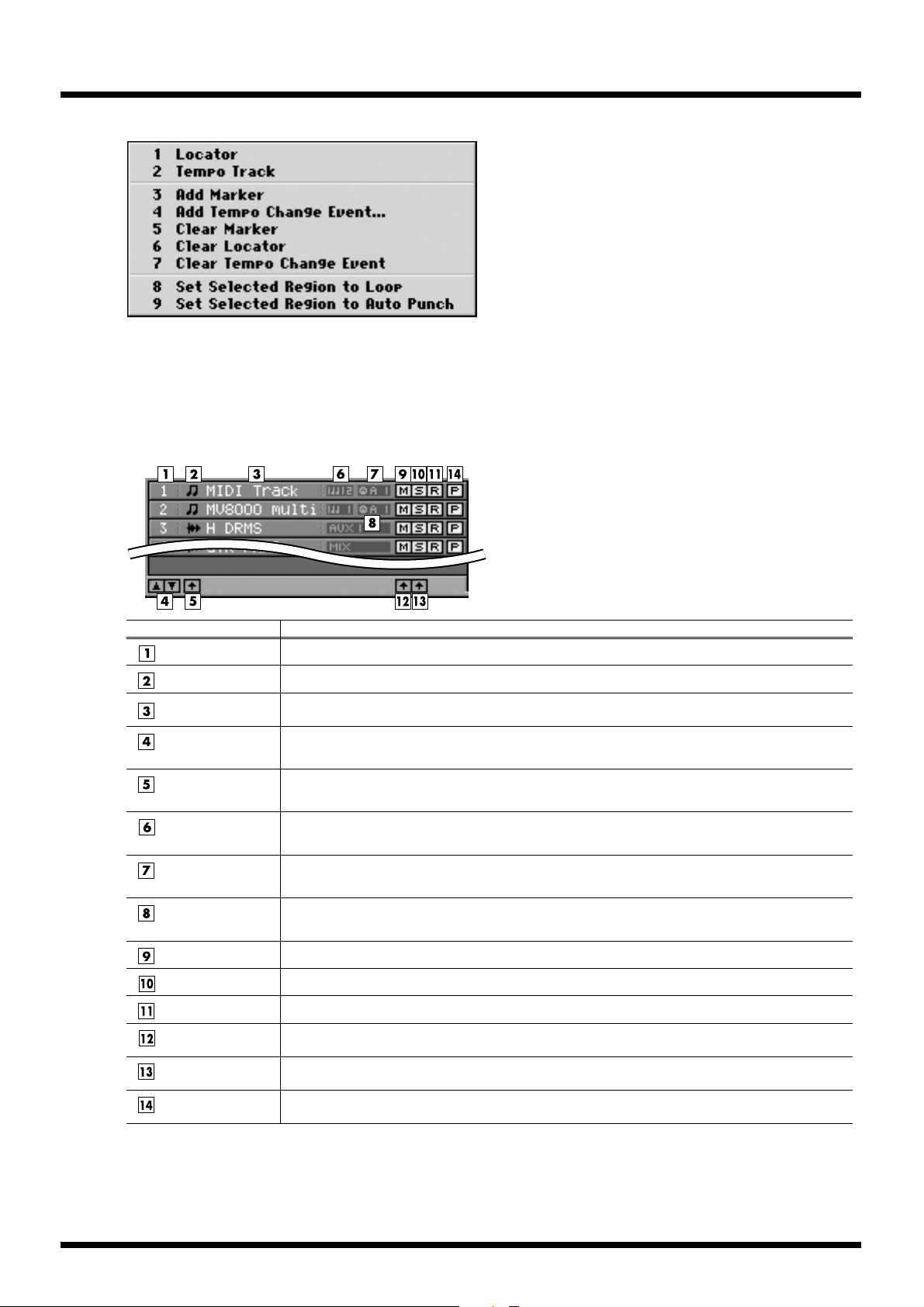
Tracklist Area
1 Locator
The LOCATOR popup will appear.
You can specify a locator number and register a time locationi for it.
2 Tempo Track
The TEMPO TRACK popup will appear.
The tempo track lets you specify the tempo and time signature.
3 Add Marker
This adds a marker at the current time location.
4 Add Tempo Change Event...
The ADD TEMPO CHANGE EVENT popup will appear.
Here you can input or edit tempo events.
5 Clear Marker
Erase Marker in place which carried out the right-click.
6 Clear Locator
Erase Locator in place which carried out the right-click.
7 Clear Tempo Change Event
Erase Tempo Change Event in place which carried out the right-click.
8 Set Selected Region to Loop
This sets the selected region as the Loop region.
9 Set Selected Region to Auto Punch
This sets the selected region as the Auto Punch region.
Track Number
Track Type Icon
Track Name
Track Move Up/
Down button
All Track Select but-
ton
Output Assign
(Instrument)
Output Assign
(MIDI)
Output Assign (Au-
dio)
Mute button
Solo button
Record button
All Track Mute Off
button
All Track Solo Off
button
Track Parameter
button
Explanation
Display the Track number. You can click here to make that number the current track.
This indicates the type of track. You can click here to select or de-select that track.
Display the name of the track. When you double-click here, the EDIT TRACK NAME popup window
will appear, allowing you to edit the name of the track.
You can click these to move the current track upward or downward (i.e., change their order).
Click this to select or de-select all tracks.
This indicates the instrument part played by the current track.
Specifies the MIDI connector and channel used for MIDI output of the data from the MIDI track.
Specifies the output connector from which the audio recorded on the track will be output.
Click this to turn Mute on (yellow) or off.
Click this to turn Solo on (light blue) or off.
Click this to switch the current track.
Click this to defeat Mute for all tracks.
Click this to defeat Solo for all tracks.
Click this to display the TRACK PARAMETER popup window for the corresponding track.
14
Page 15
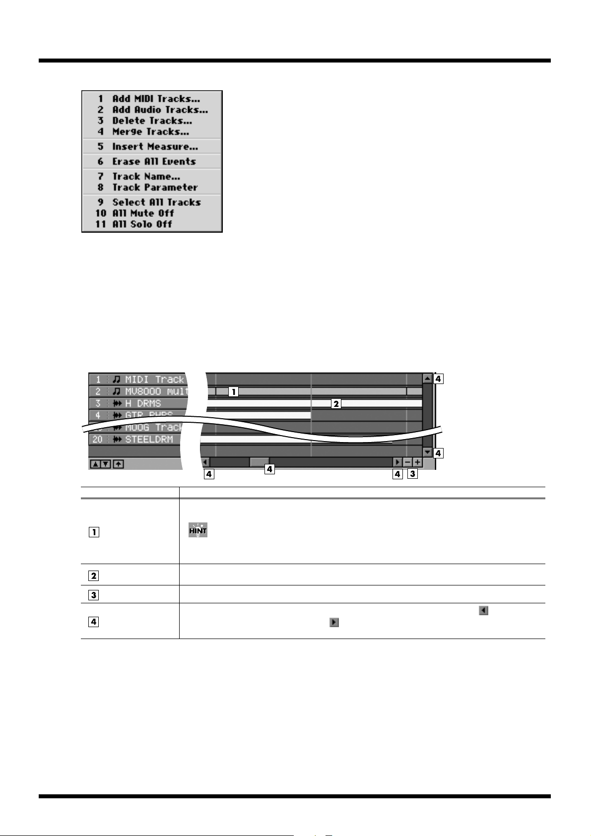
Right-click on the Tracklist Area
fig.tracklist-area2
Playlist Area
1 Add MIDI Tracks...
The ADD MIDI TRACKS popup will appear. Add one or
more MIDI tracks for recording data in your current song.
2 Add Audio Tracks...
The ADD AUDIO TRACKS popup will appear.
Add one or more Audio tracks for recording data in your current song.
3 Delete Tracks...
The DELETE TRACKS popup will appear. Here you can delete the tracks.
4 Merge Tracks...
The MERGE TRACKS popup will appear.
Here you can combine multiple MIDI tracks into a single track.
5 Insert Measure...
The INSERT MEASURE popup will appear.
Here you can insert blank measures at the specified measure location.
6 Erase All Events
Deletes the all events of current track.
A confirmation message will appear before the data is erased.
7 Track Name...
The EDIT TRACK NAME popup will appear.
You can change the name of the track.
8 Track Parameter
The TRACK PARAMETER popup will appear.
9 Select All Tracks
Select or de-select all tracks.
10 All Mute Off
Defeat Mute for all tracks.
11 All Solo Off
Defeat Solo for all tracks.
MIDI Event
Audio Event
Zoom button
Scroll button/bar
Explanation
These boxes indicate MIDI events. They are color-coded according to the assigned instrument part.
When you double-click a MIDI event, the PIANO ROLL EDIT popup window will appear.
When you holding down [JUMP] and double-click a MIDI event, the EVENT LIST popup will
appear.
These boxes indicate audio events. When you double-click an audio event, the AUDIO EVENT PA-
RAMETER popup window will appear.
These buttons expand (+) or shrink (-) the time axis of the playlist.
Here you can move the displayed portion of the play list along the time axis. Click to move to-
ward the beginning of the song, or click to move toward the end of the song. You can drag the
scroll bar to move the current time location accordingly.
15
Page 16
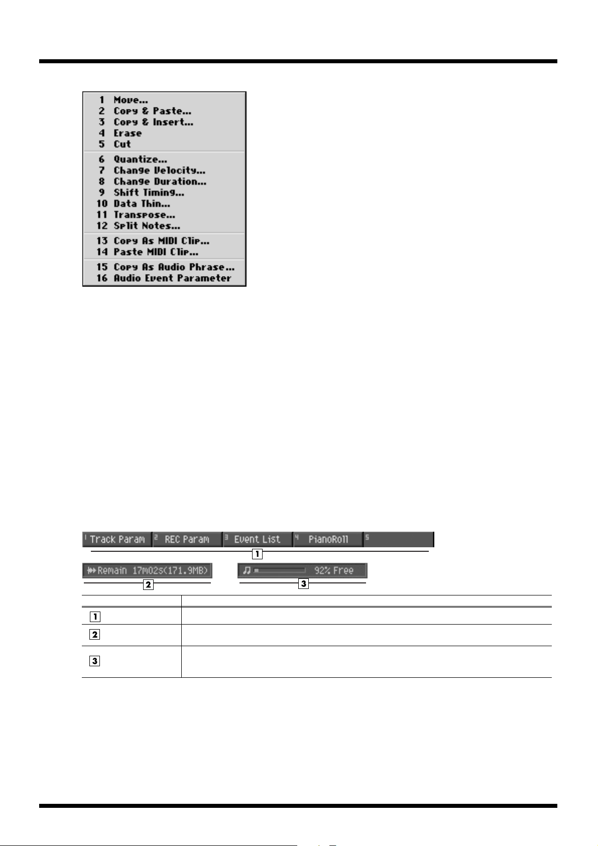
Right-click on the Playlist Area
1 Move...
The MOVE popup will appear.
Moves the data of the selected region to the specified location.
2 Copy&Paste...
The COPY&PASTE popup will appear.
Copies the data of the selected region to the specified location.
3 Copy&Insert...
The COPY&INSERT popup will appear.
Inserts the data of the selected region to the specified location.
4 Erase
Deletes the data. The deleted region will be blank.
5 Cut
Deletes the data. Subsequent data will be moved forward.
6 Quantize...
The QUANTIZE popup will appear.
Adjust the timing of MIDI note events in the way you specify.
7 Change Velocity...
The CHANGE VELOCITY popup will appear.
Changes the velocity of MIDI note events.
8 Change Duration...
The CHANGE DURATION popup will appear.
Changes the duration (note length) of MIDI note events.
9 Shift Timing...
The SHIFT TIMING popup will appear. Moves the events of the selected
region forward or backward in units of one tick (1/480th of a quarter note).
10 Data Thin...
The DATA THIN popup will appear.
Thins-out events of the selected region to reduce the amount of data.
11 Transpose...
The TRANSPOSE popup will appear.
Tr ansposes the pitch of note events in the selected region, in units of a semitone.
12 Split notes...
The SPLIT NOTE popup will appear.
This lets you extract only specific note events from a track,
and move them to a specified other track.
13 Copy As MIDI Clip...
The COPY AS MIDI CLIP popup will appear.
Add the specified data to the MIDI clip library.
14 Paste MIDI Clip...
The PASTE MIDI CLIP popup will appear.
Paste the MIDI clip from the MIDI clip library into the current song.
15 Copy As Audio Phrase...
The COPY AS AUDIO PHRASE popup will appear.
Here you can copy the selected data to the velocity pads.
16 Audio Event Parameter
The COPY AS MIDI CLIP popup will appear.
Adjust the parameters of the event of an selected audio track.
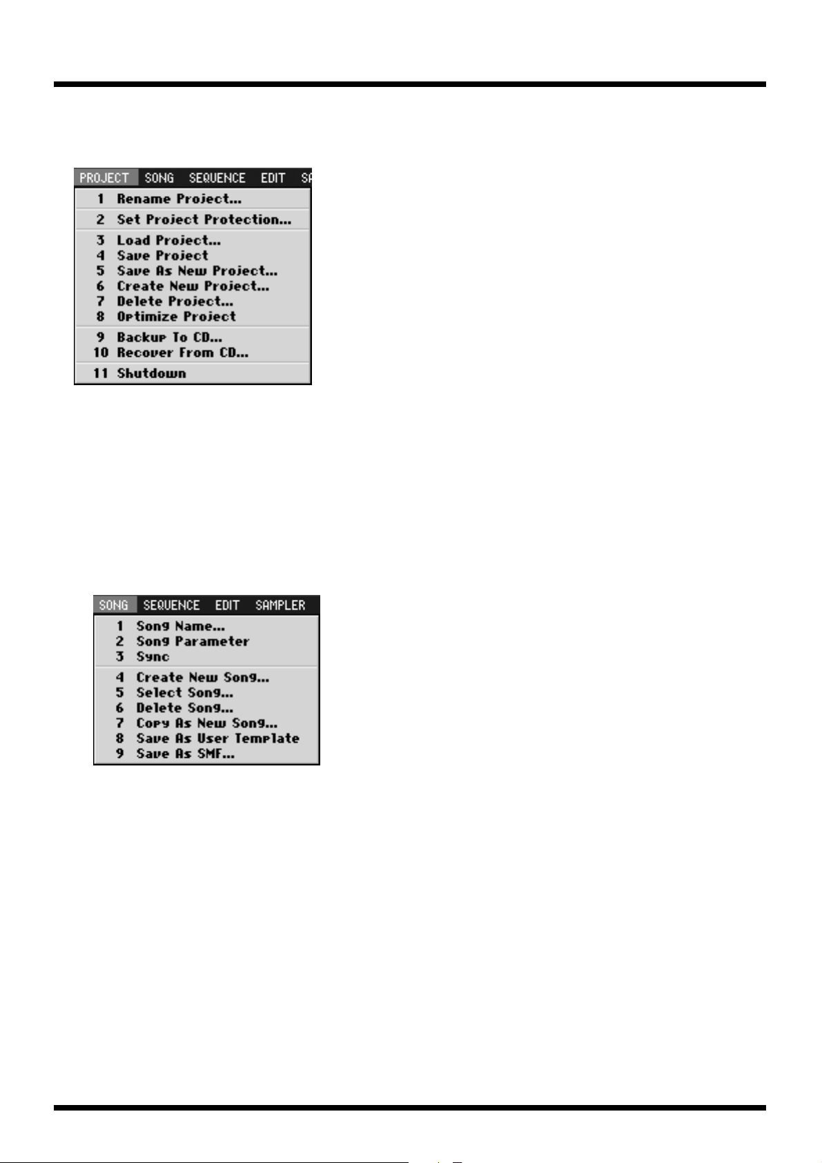
● Function Block
Function buttons
Wave Memory
meter
Sequence Memory
meter
Explanation
The [F1]–[F5] buttons correspond to functions displayed at the bottom of the LCD.
If it is in the state which can do the direct recording, the remaining recordable time and the remaining
amount of memory are displayed.
In the state which can do the sequence recording, green meter is displayed. This indicates the amount
of sequence data that has been recorded. The numerical value shows the proportion of free area available for recording events into the sequencer.
16
Page 17
● Menu Bar
PROJECT
Manage the project and make project setting.
1 Rename Project...
The EDIT PROJECT NAME popup will appear. Assign a name to the project.
2 Set Project Protection...
The SET PROJECT PROTECTION popup will appear.
Protect a project saved on disk from being overwritten or deleted.
3 Load Project...
The LOAD PROJECT popup will appear. Load a project, making it the current project.
4 Save Project
"Save Current Project?" message will appear. Save the current project.
5 Save As New Project...
The SAVE AS NEW PROJECT popup will appear.
Here you can save the current project under a different name, and then make it the current project.
6 Create New Project...
The CREATE NEW PROJECT popup will appear. Create a new project.
7 Delete Project...
The DELETE PROJECT popup will appear. Delete an unwanted project.
8 Optimize Project
"Optimize Project?" message will appear.
This will reorganize the samples used by the current project
in order to make the most efficient use of memory.
9 Backup To CD...
The BACKUP PROJECT TO CD popup will appear.
Backup the current project to a CD-R/RW disc.
10 Recover From CD...
The RECOVER PROJECT FROM CD popup will appear.
Recover (restore) a backed-up project from CD into the MV-8000 with the name you specify.
11 Shutdown
"SHUTDOWN Are you sure?" message will appear.
You must execute this operation before powering-off the MV-8000.
SONG
Manage the song and make various settings for the current song.
1 Song Name...
The EDIT SONG NAME popup will appear. You can change the name of the current song.
2 Song Parameter
The SONG PARAMETER popup will appear. Make settings for the current song.
3 Sync
The SYNC popup will appear. Make synchronization settings.
4 Create New Song...
The CREATE NEW SONG popup will appear. Create a new song within the current project.
5 Select Song...
The SELECT SONG popup will appear. Change the current song by recalling the desired song.
6 Delete Song...
The DELETE SONG popup will appear. Delete an unwanted song.
7 Copy As New Song...
The COPY AS NEW SONG popup will appear.
Copy the current song, and switch the current song to be the resulting copy.
8 Save As User Template
Save a track structure or loop settings to a song template.
9 Save As SMF...
Save the current song in SMF (Standard MIDI File) format 1.
17
Page 18
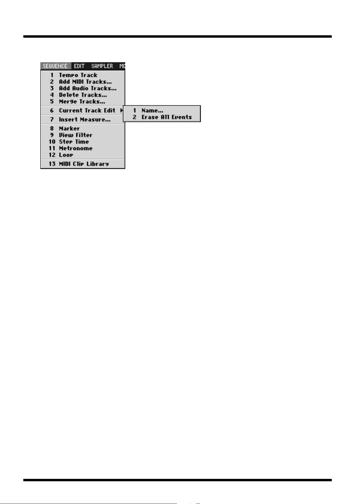
SEQUENCE
Perform sequencer-related operations.
1 Tempo Track
The TEMPO TRACK popup will appear.
The tempo track lets you specify the tempo and time signature.
2 Add MIDI Track...
The ADD MIDI TRACKS popup will appear.
Add one or more MIDI tracks for recording data in your current song.
3 Add Audio Track...
The ADD AUDIO TRACKS popup will appear.
Add one or more Audio tracks for recording data in your current song.
4 Delete Tracks...
The DELETE TRACKS popup will appear. Here you can delete the tracks.
5 Merge Tracks...
The MERGE TRACKS popup will appear. Here you can combine multiple MIDI tracks into a single track.
6 Current Track Edit >
1 Name...
2 Erase All Events
7 Insert Measure...
The INSERT MEASURE popup will appear.
Here you can insert blank measures at the specified measure location.
8 Marker
The MARKER popup will appear. Here you can add or delete markers.
9 View Filter
The VIEW FILTER popup will appear.
Here you can select the MIDI events that can be viewed
and edited in the SEQUENCE screen and EVENT LIST screen.
10 Step Time
The STEP TIME popup will appear.
Here you can specify the interval by which the STEP buttons will change the time location.
11 Metronome
The METRONOME popup will appear. Here you can make metronome settings.
12 Loop
The LOOP popup will appear. Here you can make loop settings for loop play.
13 MIDI Clip Library
The MIDI CLIP LIBRARY popup will appear. Here you can rename or delete items in the MIDI clip library.
The EDIT TRACK NAME popup will appear. Here you can change the name of the track.
Deletes the all events of current track. A confirmation message will appear before the data is erased.
18
Page 19
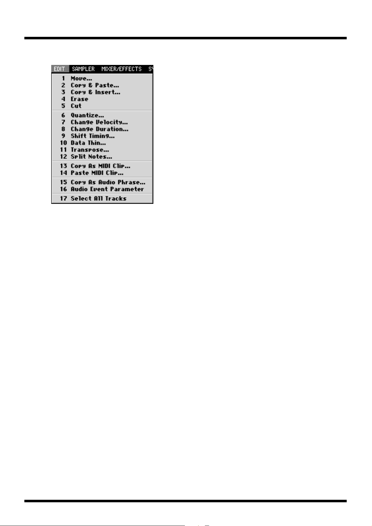
EDIT
You can edit the track.
1 Move...
The MOVE popup will appear.
Moves the data of the selected region to the specified location.
2 Copy&Paste...
The COPY&PASTE popup will appear.
Copies the data of the selected region to the specified location.
3 Copy&Insert...
The COPY&INSERT popup will appear.
Inserts the data of the selected region to the specified location.
4 Erase
Deletes the data. The deleted region will be blank.
5 Cut
Deletes the data. Subsequent data will be moved forward.
6 Quantize...
The QUANTIZE popup will appear.
Adjust the timing of MIDI note events in the way you specify.
7 Change Velocity...
The CHANGE VELOCITY popup will appear.
Changes the velocity of MIDI note events.
8 Change Duration...
The CHANGE DURATION popup will appear.
Changes the duration (note length) of MIDI note events.
9 Shift Timing...
The SHIFT TIMING popup will appear.
Moves the events of the selected region forward or backward in units
of one tick (1/480th of a quarter note).
10 Data Thin...
The DATA THIN popup will appear.
Thins-out events of the selected region to reduce the amount of data.
11 Transpose...
The TRANSPOSE popup will appear.
Tr ansposes the pitch of note events in the selected region, in units of a semitone.
12 Split notes...
The SPLIT NOTE popup will appear.
This lets you extract only specific note events from a track,
and move them to a specified other track.
13 Copy As MIDI Clip...
The COPY AS MIDI CLIP popup will appear.
Add the specified data to the MIDI clip library.
14 Paste MIDI Clip...
The PASTE MIDI CLIP popup will appear.
Paste the MIDI clip from the MIDI clip library into the current song.
15 Copy As Audio Phrase...
The COPY AS AUDIO PHRASE popup will appear.
Here you can copy the selected data to the velocity pads.
16 Audio Event Parameter
The AUDIO EVENT PARAMETER popup will appear.
Adjust the parameters of the event of an selected audio track.
17 Select All Tracks
Select or de-select all tracks.
19
Page 20
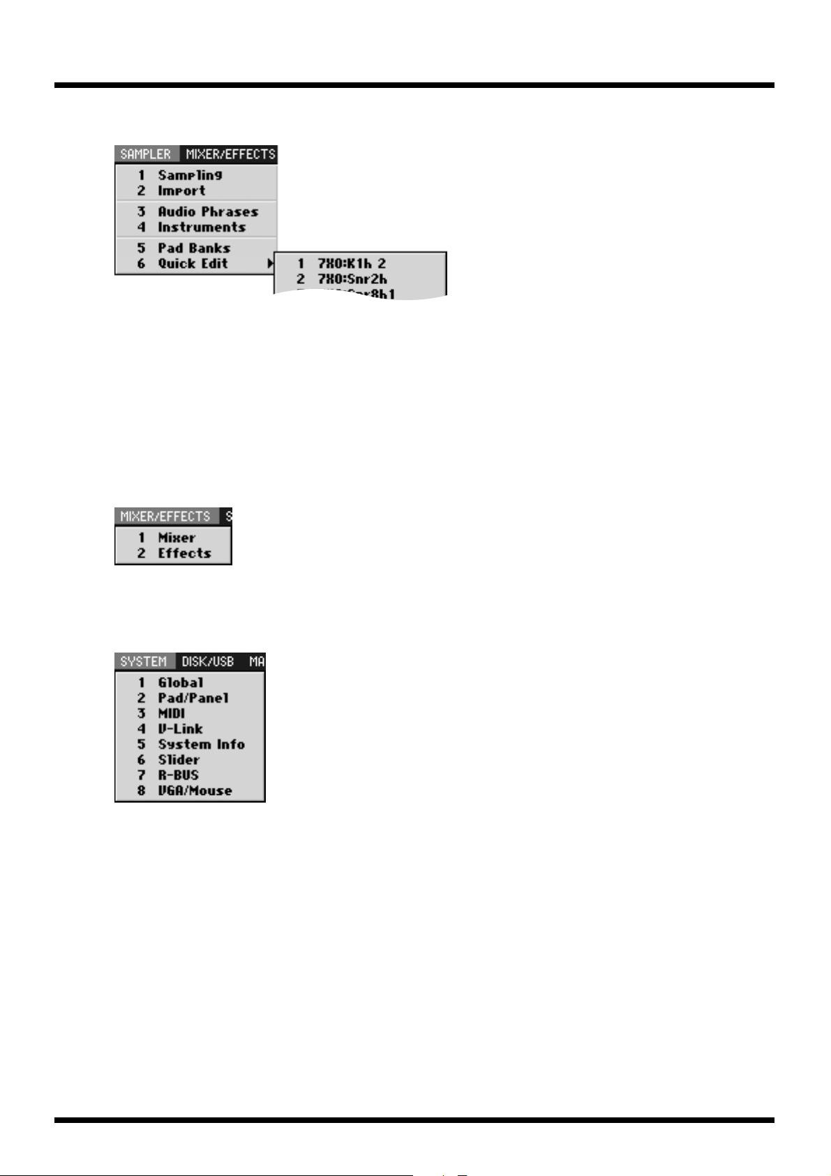
SAMPLER
Here you can sample or import of audio sources, and make sampler setting.
1 Sampling
The SAMPLING popup will appear. Here you can make sampling setting and perform sampling.
2 Import
The IMPORT popup will appear. Here you can import of music data from hard disk or CD.
3 Audio Phrases
The AUDIO PHRASES popup will appear. Here you can edit the audio phrases.
4 Instruments
The INSTRUMENTS popup will appear. Here you can edit the instruments.
5 Pad Banks
The PAD BANKS popup will appear. The PAD BANKS popup will appear.
Here you can switch the pad bank of the velocity pads.
6 Quick Edit >
This lets you edit an audio phrase or partial assigned to a velocity pad.
Use the sub-menu to select the number of the velocity pad.
MIXER/EFFECTS
Here you can make mixer or effect setting.
1 Mixer
The MIXER popup will appear.
Here you can adjust the volume and panning of the audio tracks and instrument parts.
2 Effects
The EFFECTS popup will appear.
Here you can make settings for the built-in MFX, Delay/Chorus and Reverb.
SYSTEM
Here you can make system setting for the MV-8000.
1 Global
The GLOBAL popup will appear.
Here you can make settings for the overall system of the MV-8000.
2 Pad/Panel
The SYSTEM PAD popup will appear.
Here you can make settings for the velocity pads, top panel buttons, knobs, and sliders.
3 MIDI
The MIDI popup will appear. Here you can make MIDI settings.
4 V-Link
The V-LINK popup will appear. Here you can make V-LINK settings.
5 System Info
The SYSTEM INFORMATION popup will appear.
Here you can view information about memory usage and the status of the installed options.
6 Slider
The SYSTEM ASSIGNABLE SLIDER popup will appear.
Here you can specify the functions assigned to the sliders.
7 R-BUS
The R-BUS popup will appear. Here you can make R-BUS settings.
8 VGA/Mouse
The VGA/MOUSE popup will appear.
Here you can specify the signal that will be sent to the external display,
and adjust the sensitivity of the mouse.
20
Page 21
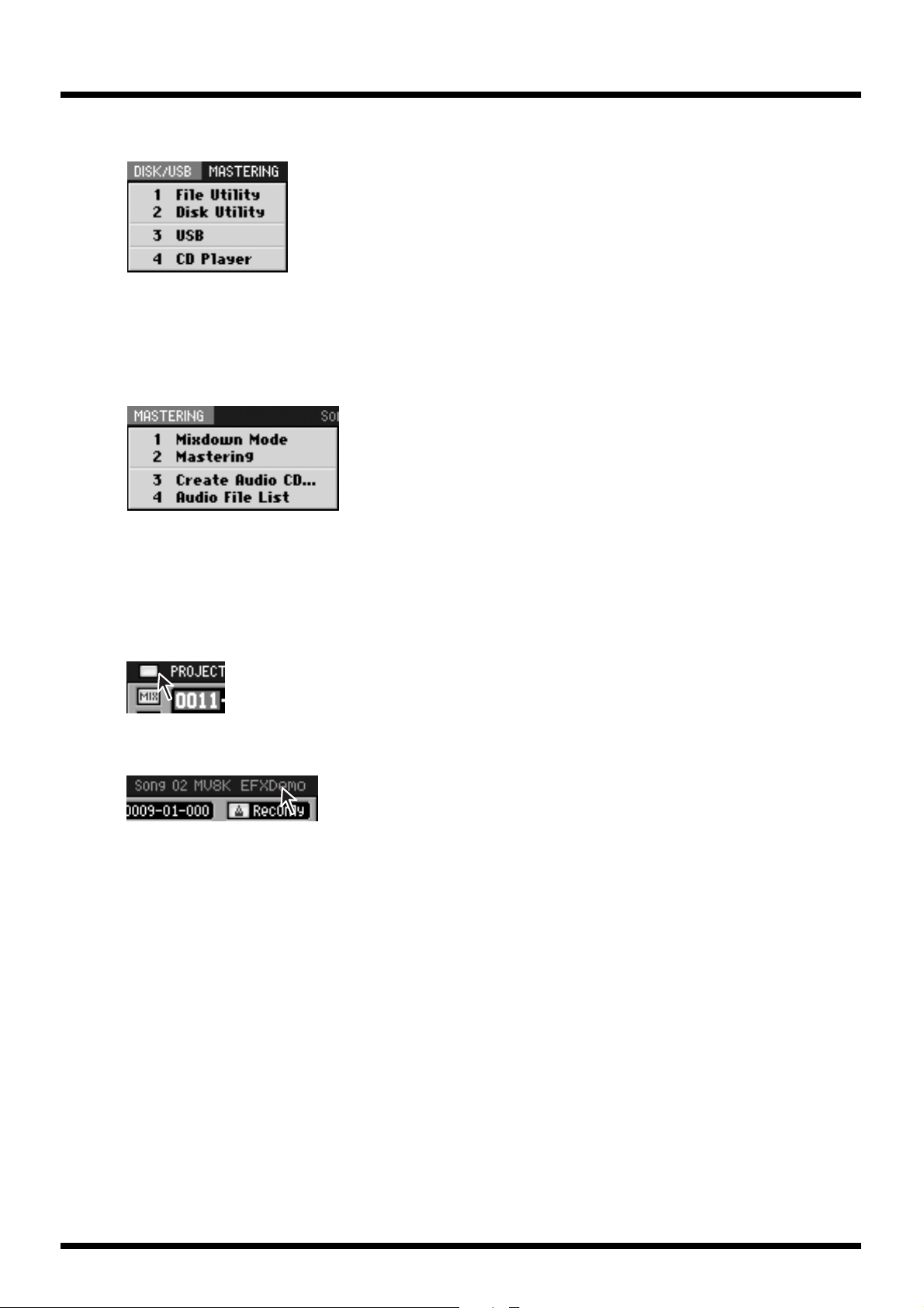
DISK/USB
Here you can make settings for the MV-8000’s disk and for USB.
1 File Utility
The FILE UTILITY popup will appear. Here you can manage files by copying, moving, or deleting them.
2 Disk Utility
The DISK UTILITY popup will appear. Here you can check the disk and perform maintenance.
3 USB
The USB popup will appear.
This switch the MV-8000 to USB-connection mode, which lets you transfer data between
the internal hard disk and your computer.
4 CD Player
The CD PLAYER popup will appear. Here you can play back an audio CD.
MASTERING
Here you can mixdown your completed song to a two-track master, and create an
audio CD.
1 Mixdown Mode
A confirmation message will appear. Turns mixdown mode on/off.
2 Mastering
The MASTERING popup will appear.
Here you can use the mastering tool kit to master an audio file.
3 Create Audio CD...
The CUE SHEET popup will appear.
Here you can specify the song order in which the audio files
will be written to the CD-R/RW disc.
4 Audio File List
The AUDIO FILE LIST popup will appear.
Here you can audition or delete mixdown data or mastering data.
All Popup Close button
This button closes all popup windows that are currently open in the screen.
Song Number/Song Name
This shows the number and name of the currently-loaded song
21
Page 22
Operation section
Operation section
Quick Tour
The following pages explain the most important operations in VGA mode. Please take
this quick tour in order to get a feel for using VGA mode to operate the MV-8000.
Preparations
Load a project that contains data, such as “MVDEMO_SONG”.
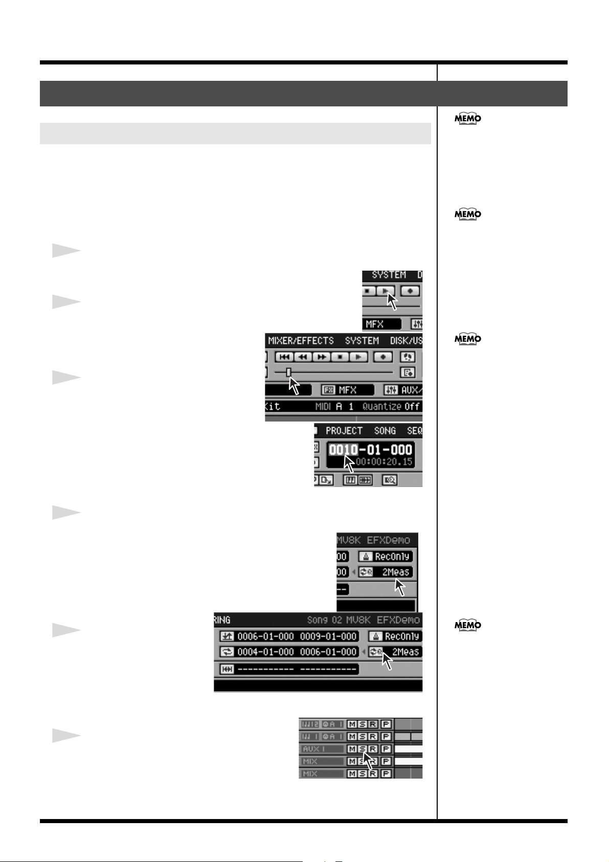
● Playback and changing the time location
1
Click the Play button.
The song will begin playing.
2
Click a desired point on the song position bar.
The song playback position will move to
the location on which you clicked.
3
In the current time display area, click
the measure, beat, or tick field.
This quick tour explains
mainly MIDI tracks and
instruments, but the same
explanations also apply to
audio tracks and audio
phrases.
Loading a project – In the
menu bar, click “PROJECT”; in
the list that appears, click
“Load Project...”
You can also drag the knob
(handle) of the bar.
The numerical display will turn blue; now
you can edit the value. The song playback position will
change when you move the mouse wheel to increase or
decrease the value.
● Loop playback
1
Click the Loop Quick Set Length indicator.
A list will appear; click the number of measures you want to
use (e.g., 2Meas).
2
Click the Loop Quick Set
button
Loop playback will be
enabled.
● Solo Play
Playback will loop for the
number of measures you
specified in step 1.
22
1
Click the Solo button.
The Solo button will turn light blue. Only the light
blue tracks will play. When you click once again,
solo will be defeated (the button will go dark).
Page 23
2
b
Click the All Track Solo Off button.
All solo settings will be defeated.
● Display-related functions
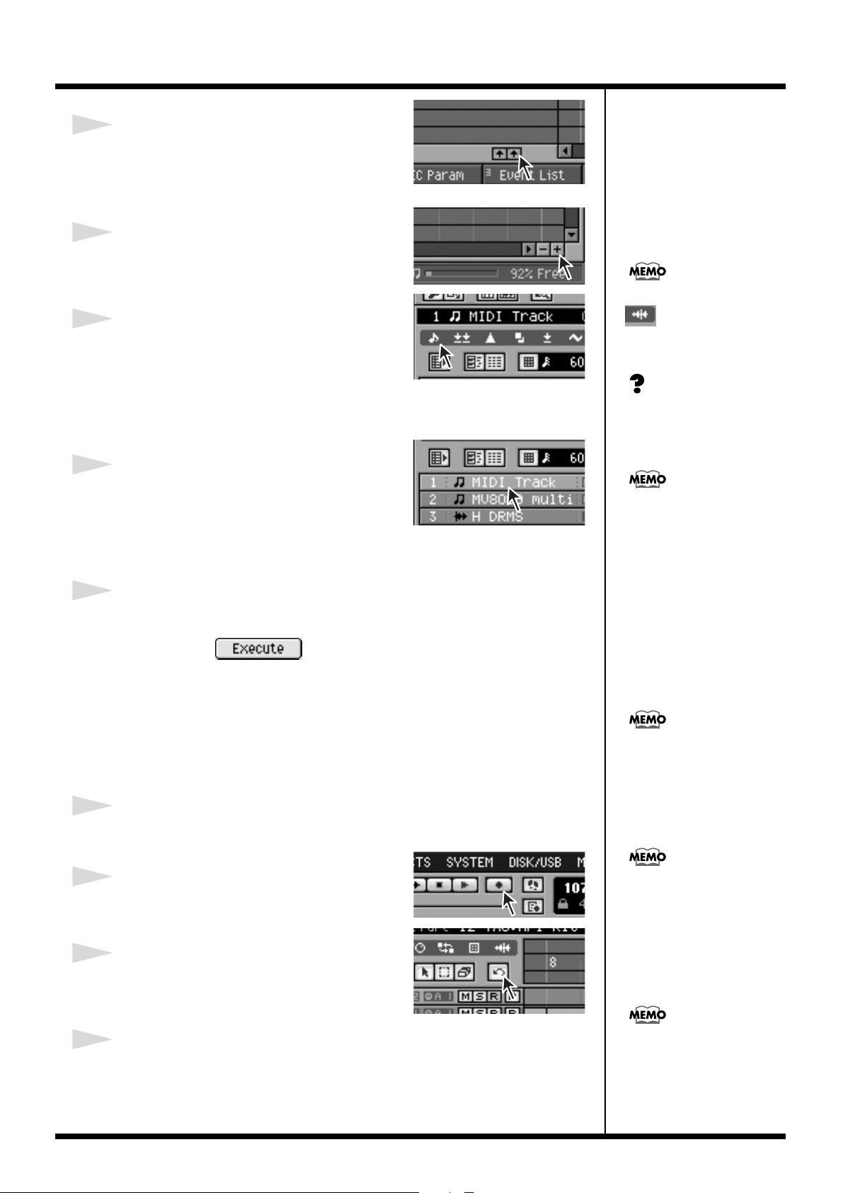
1
Click the zoom button.
The dimension of the play list’s horizontal axis (time
axis) will change.
In the same way, you can click
2
Click the note event icon in the View Filter
icons.
Of the events displayed in the play list, this switches
MIDI note events between displayed and hidden.
● Selecting and adding tracks
1
Click the Track Name of the MIDI Track.
The color of the track will change, and it will
become the current track.
When you strike a pad, the patch will sound according to the Output Assign parameter
of the current track.
2
Right-click the Track Name of the current Track.
A list will appear; click “Add MIDI Tracks... .” The ADD MIDI TRACKS popup will
appear, and click .
A MIDI track will be added, and will become the current track.
● Recording and Undo
Preparations
• If looping is turned off, click the Loop button.
• If the sequencer is stopped, click the Play button.
1
Strike the pads to rehearse your recording.
It’s a good idea to practice before you begin recording.
to switch audio events
etween displayed and
hidden.
Current Track – This refers to
the track that is currently
selected as the target of your
operations.
If there’s no sound, try clicking
the pad bank button to change
the pad bank. Alternatively,
try a different track.
Loading a project – In the
menu bar, click “PROJECT”; in
the list that appears, click
“Load Project...”
2
Click the Record button.
Recording will begin. Strike the pads to perform.
The loop region will be
recorded repeatedly.
3
Click the Undo button
Cancel the results of an recording (Undo). The Undo
button will blink.
4
Click the Undo button again.
The content you erased by Undo will be recovered (Redo). The Undo button will lit
(light blue). Undo and Redo will alternate each time you click.
When you execute Undo, the
recording state will be
defeated, and you will return
to playback.
23
Page 24
● Play Quantize
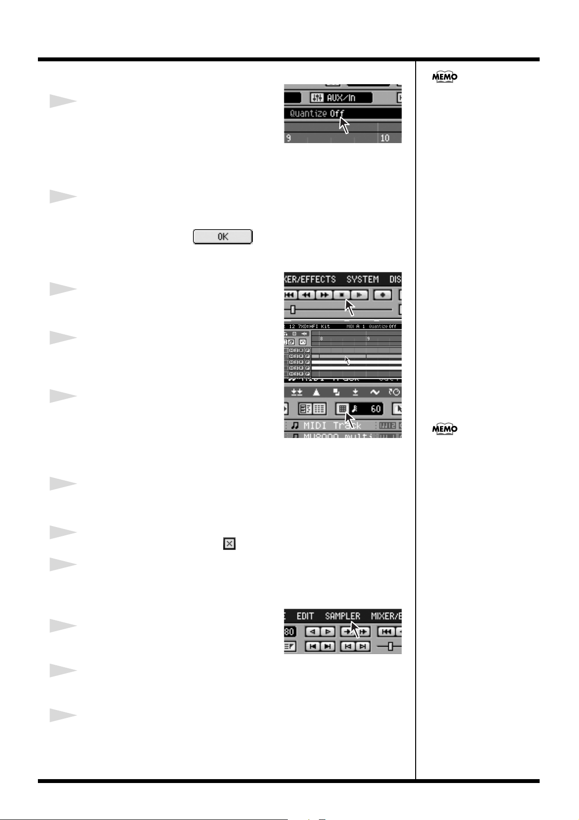
1
Click the display of the Quantize Type.
The list will appear. The result will depend on the
Quantize Type. The parameters at right let you
specify the effect in greater detail.
● Editing the name of a track
1
Double-click The Track Name of current track.
The EDIT TRACK NAME popup will appear. Click a key on the keyboard to edit the
name of the track. Then click .
● Editing an event
1
Click the Stop button.
Recording/playback will stop.
2
Drag and drop an event.
The event will move.
This operation only modifies
the way in which the data is
played back. This means that
you can always defeat the
effect simply by turning this
“Off”.
3
Click the Snap button.
Snap mode will be switched on/off. In Snap mode,
the mouse pointer will always be located at fixed
intervals. When dragging and dropping an event,
this lets you ensure that the event will always be aligned to the beginning of a measure
(or whatever interval you specify).
4
Double-click an event.
A popup window will appear, allowing you to edit the selected event in greater detail.
5
Specify the parameters, then click .
6
The popup will close.
● Edit the sound
1
Click “Sampler” on the menu bar.
A list will appear.
2
Move the mouse cursor (i.e., point) to “Quick Edit.”
Another list will appear.
To edit a value, move the
mouse pointer to it and use the
left button to drag it upward
or downward.
24
3
Click the partial name you want to edit.
The PARTIAL EDIT popup or AUDIO PHRASE EDIT popup will appear.
Page 25
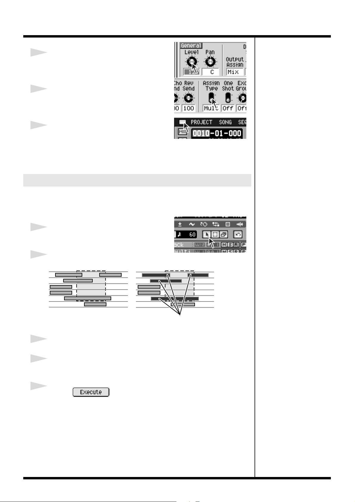
4
Drag the knob whose value you want to edit.
The knob will turn, and the parameter value will
change according to the distance to which you drag.
5
Click the switch.
The switch indication will change, and the
parameter value will change accordingly.
6
Click the All Popup Close button.
All of the popups will close.
This completes the Quick Tour.
Functions we didn’t discuss here can also be controlled in the same way.
Using the mouse to edit sequence data
● Selecting a region that you want to edit, and executing Move
Here’s how to select a region of data recorded in a track, and move it to another time
location or another track.
1
Click the Arrow button
Now you can use Arrow mode to make a selection.
2
Drag over the region you want to select.
When you drag to specify
a region like this
all data falling within
the specified region will be selected.
3
In the menu bar, click “EDIT” (or right-click) to display a popup menu.
4
Click the “Move... .”
The MOVE popup will appear. Use the To parameter to specify the move-destination.
5
Click the .
The Move operation will be executed.
25
Page 26

● Using drag & drop to execute the Move operation
1. Click the Arrow button or Range button.
2. Drag the region you want to edit.
3. Point the selected region.
4. Drag and drop the region at the desired destination.
While dragging, the mouse pointer will change to . When you drop the data
you were dragging, it will be moved to the location of the mouse pointer. The
mouse pointer will return to .
● Using the Range Tool to select a region
When you click the Range button, the mouse pointer will change to . When
using the Range tool, only the portion included in the region will be selected for
the operation.
When you enclose
a region like this
the enclosed data
will be selected.
● Using the Eraser Tool to delete a data
When you click the Eraser button, the mouse pointer will change to . You can
delete data by clicking it with the Eraser tool.
Using the mouse to edit a MIDI track (PIANO ROLL EDIT screen)
● Select the region you want to edit, and execute the move
operation
Here’s how to select a region of recorded note events in the piano roll display, and
move them to another time location or to other note numbers.
1
Click the Arrow button.
Now you can use Arrow mode to make a selection.
2
Drag over the region you want to select.
26
When you drag to specify
a region like this
all data falling within
the specified region will be selected.
Page 27

3
Click the .
The popup menu will appear.
4
Double-click the “Move... .”
The MOVE popup will appear. Use the To parameter to specify the move-destination.
5
Click the .
The Move operation will be executed.
● Using drag & drop to execute the Move operation
1. Click the Arrow button or Range button.
2. Drag the region you want to edit.
3. Point the selected region.
4. Drag and drop the region at the desired destination.
While dragging, the mouse pointer will change to . When you drop the data
you were dragging, it will be moved to the location of the mouse pointer. The
mouse pointer will return to .
● Using the Range Tool to select a region
When you click the Range button, the mouse pointer will change to . When
using the Range tool, only the portion included in the region will be selected for
the operation.
When you enclose
a region like this
the enclosed data
will be selected.
● Using the Eraser Tool to delete a data
When you click the Eraser button, the mouse pointer will change to . You can
delete data by clicking it with the Eraser tool.
You can Copy data by holding
down [SHIFT] while you drag
and drop the data.
27
Page 28

Step Recording
● Step recording a MIDI track (STEP REC screen)
Explanation
Step Time
Step Time
button
Duration
Velocity
Note number
(Keyboard)
Piano Roll
Velocity View
Specifies the note value of the notes you will input.
Click this button you specify the note value of the notes you will input.
Specifies the actual length of the note, as a percentage of the note value
you specified for Step Time.
Specifies the strength of the note.
The note numbers (keys) are shown from bottom to top. Since the
actual pitches correspond to the note numbers, the displayed location
of the note tells you the pitch.
This shows the note events. The horizontal axis is time, and the vertical
axis is note number (pitch). you can change the note number or time
location by moving the displayed note event.
Indicate the velocity of the note event. The velocity is shown as a pair
with the note event; a longer bar indicates a stronger velocity.
Explanation
Reverts the preceding input.
Connects (extends) the event at the current time to the next step.
Inputs a rest (silence).
● Step recording an Audio track (AUDIO PHRASE STEP REC
screen)
Explanation
Step Time
Step Time button
Duration
Velocity
Specifies the length of the audio events you will input.
Click this button you specify the length of the audio events you
will input.
Specifies the actual length of the audio event, as a percentage of
the length you specified for Step Time.
Specifies the strength of the audio event.
Explanation
Reverts the preceding input.
28
Connects (extends) the event at the current time to the next step.
Inputs a rest (silence).
Page 29
Changes in Sampling and Importing
Sampling
The sampling procedure and specifications have been changed. The changes are as
follows.
• The SAMPLING screen will appear immediately when you press [SAMPLING].
The SAMPLING screen will appear without the SAMPLING MENU screen being
displayed first. This allows you to begin recording immediately. Check the sample
assignments in the RESULT screen before you make settings.
• The number of samples divided by the Auto Divide function has changed from 16 to
96.
• You can now choose the sample preview (audition) method in the RESULT screen.
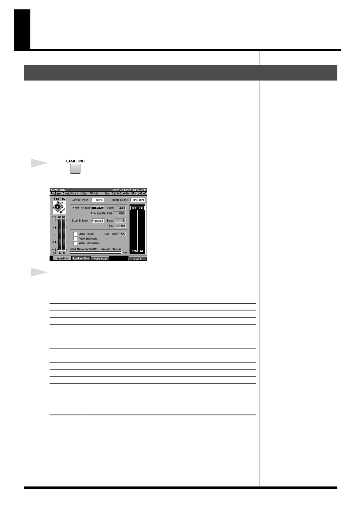
1
Press .
The SAMPLING screen will appear.
fig.sampling-screen
2
Set the parameters for sampling.
• Sample Type
Specifies the number of channels that will be sampled.
Range Explanation
Mono Monaural (one channel)
Stereo Stereo (two channels)
• Input Select
Selects the input source for sampling or recording.
Range Explanation
Analog Analog input from the PHONO connectors or MIC/LINE connectors.
Coaxial Coaxial digital input
Optical Optical digital input
R-BUS Digital input from R-BUS (channels 1 and 2)
• Start Trigger
Specifies how sampling will begin.
Range Explanation
Manual Sampling will be started manually.
Level Sampling will be triggered by the input level.
Pad Sampling will begin when you strike a pad.
Play Sampling will begin when you play back the sequencer.
• Level
Specifies the response level when using the input level to start sampling.
Range: -36, -24, -18, -12, -8, -4 dB
29
Page 30

Changes in Sampling and Importing
b
• Pre Sample Time
This specifies the duration of sound from before the sampling start time that will be
included in the recorded sample.
Range: 0, 20 40, 80, 160, 320, 640, 1000 ms
• Stop Trigger
Specifies how sampling will stop.
Range Explanation
Manual Sampling will be stopped manually.
Beat
Time Sampling will stop after the time specified by the Length parameter.
• Beat/Time
Specifies the time after which sampling will stop when Stop Trigger parameter is Beat
or Time.
Range: Beat 1–8–20000
• Auto Divide
The Auto Divide function detects regions of silence within the sample, and divides the
sample into several samples at these points.
Range: Off, On
• Gap Time
Silences of a duration longer than the specified time will be considered as silence. The
Gap Time parameter is valid if Auto Divide parameter is on.
Range: 0.5, 1.0, 1.5, 2.0 sec
• Auto Emphasis
Automatically pre-emphasis processes after sampling.
Range: Off, On
• Auto Normalize
Automatically normalizes the level after sampling.
Range: Off, On
Sampling will stop after the number of beats specified by the Length
parameter.
Time 000:01–000:02–100:00 (minutes : seconds)
A maximum of 96 samples can
e divided.
3
Press (Start).
“Now Sampling..” message will appear, and starts sampling.
4
Press (Stop).
Stops sampling. The RESULT screen will then appear.
5
Set the parameters for adjusting.
• Start Point / End Point
Specify the points at which the sample will start playing and stop playing. The Start
Point - End Point region is highlighted.
Range: 000000000.000–The end of sample
RESULT (MULTIPLE) popup
will appear when Auto Divide
parameter is on.
30
Page 31
Changes in Sampling and Importing
• BPM Base Note
Draws measure and beat lines on the displayed sample.
Range: , , (initial value), , / x 1–x 4–x 65535
• Original Key
Specifies the basic pitch. When you play this key, the sample will sound at its original
pitch (the pitch at which it was sampled).
Range: 0 (C -)–60 (C 4)–127 (G 9)
• Truncate
Deletes the portions of the sample before the Start Point and after the End Point.
Range: Off, On
• Normalize
Raises the overall level of the sample without allowing the maximum level to be
exceeded.
Range: Off, On
• Loop
Specifies how [F4 (Preview)] will operate. You can also make setting of loop playback
when you assign the sample to pad as a Partial or an Audio Phrase.
Value Explanation
Off The sample will audition once from the Start Point to the End Point.
On The sample will repeatedly audition from the Start Point to the End Point.
The BPM is displayed below
the BPM Base Note. The
displayed BPM value is
calculated from the BPM Base
Note setting and the playback
length of the sample.
•F buttons
F button Explanation
Discards the displayed sample will be discarded, and retries the
(Retry)
(Name)
(Quick Assign)
(Preview)
(OK)
sampling operation. The SAMPLING / RE-SAMPLING screen
will appear.
Displays the EDIT SAMPLE NAME popup, where you can edit
the sample name.
Displays the SELECT QUICK ASSIGN popup.
Auditions the currently-highlighted sample. To hear auditioning,
hold down [F4 (Preview)].
The RESULT popup will close. If Truncate or Normalize are
turned on, these operations will be performed before closing.
You can use the [PREVIEW FROM] and [PREVIEW TO] buttons to audition the region
(the side at which the cursor is located) near the Start Point or End Point.
Preview Explanation
Playback sample from a point slightly earlier (Preview Length) than the
(To)
(From)
current editing point.
Playback sample for a short time (Preview Length) from the current
editing point.
6
Press (OK).
The RESULT popup will close.
If you want to use the sampled
data as an audio phrase or
patch, press
[F3 (Quick Assign)] to get the
SELECT QUICK ASSIGN
popup window.
31
Page 32
Changes in Sampling and Importing
b
Importing
The import procedure has been improved, allowing you to collect samples more
quickly. The changes are described below.
• Press [IMPORT], then IMPORT screen will appear.
The IMPORT screen will appear without the IMPORT MENU screen being
displayed first. This allows you to import files immediately.
• More types of files can now be imported.
Akai MPC2000/2000XL and S1000/S3000 program files and sound files can be
loaded.
• Multiple files can now be imported at once.
This allows you to collect audio material more quickly.
The RESULT (MULTIPLE) popup screen does not appear when multiple files of below are
imported.
• SMF (Standard MIDI File)
Screen returns to IMPORT screen after when import process is completed.
• Roland S-700 series Patch
• Akai MPC2000/2000XL Program
• Akai S1000 Program
• Akai S3000 Program
The ASSIGN TO PART/LIBRARY popup will appear.
• Roland S-700 series Partial
The ASSIGN TO PARTIAL popup will appear.
• You can now choose the sample preview (audition) method in the RESULT popup.
•A BPM display has been added to the RESULT popup window.
You can specify the BPM (tempo) of the imported sample.
Importing the WAV or AIFF files
1
Insert the disk (floppy disk or CD-ROM) containing the file you want to import
into the drive.
2
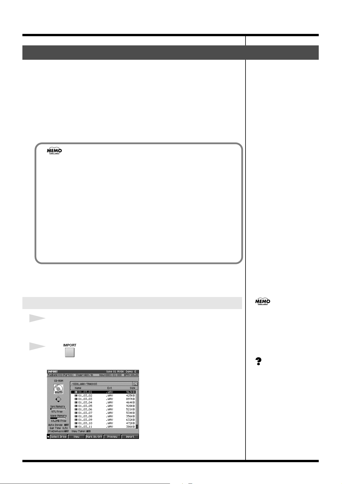
Press .
The IMPORT popup will appear.
fig.import-result-popup
You cannot create a patch
simply by loading Akai
MPC2000/2000XL program
files (.PGM) alone. The sound
files (.SND or .WAV) must also
e present in the same folder
as the program file.
Akai program files are
analogous to the MV-8000’s
patches.
32
Page 33

Changes in Sampling and Importing
3
Press (Select Drive).
The SELECT DRIVE popup will appear.
4
Use to select the disk containing the WAV/AIFF file you want to import,
and press (Select).
The contents of the disk will be displayed.
5
Use to select the WAV/AIFF file you want to import.
•F buttons
F button Explanation
Displays the SELECT DRIVE popup, letting you switch the drive
(Select Drive)
(View)
(Mark On/Off)
(Preview)
(Import)
form which to select files.
Here you can limit the type of the file that will appear in the
IMPORT screen.
Turns the check mark on/off for a file.
Auditions the currently-highlighted file. To hear auditioning,
press [F4 (Preview)].
Imports the selected or check marked file(s).
By using [F3 (Mark On/Off)]
to assign a mark to files you
want to import, you can
import multiple files in a single
operation.
By pressing [MENU] and
selecting “All Mark” you can
select or de-select all files on
the list.
6
Press (Import).
The data will be imported, and the RESULT popup window will appear.
fig.sample-result-screen
7
Specify the parameters.
• Start Point / End Point
Specify the points at which the sample will start playing and stop playing. The Start
Point - End Point region is highlighted.
Range: 000000000.000–The end of sample
• BPM Base Note
Draws measure and beat lines on the displayed sample.
Range: , , (initial value), , / x 1–x 4–x 65535
• Truncate
Deletes the portions of the sample before the Start Point and after the End Point.
Range: Off, On
When you import from an
audio CD, the SETUP TIME
popup window will appear.
For details, refer to “Importing
an audio from an audio CD
(The SET TIME popup)” (p.
36).
The BPM is displayed below
the BPM Base Note. The
displayed BPM value is
calculated from the BPM Base
Note setting and the playback
length of the sample.
33
Page 34

Changes in Sampling and Importing
• Normalize
Raises the overall level of the sample without allowing the maximum level to be
exceeded.
Range: Off, On
• Original Key
Specifies the basic pitch. When you play this key, the sample will sound at its original
pitch (the pitch at which it was sampled).
Range: 0 (C -)–60 (C 4)–127 (G 9)
• Loop
Specifies how [F4 (Preview)] will operate. You can also make setting of loop playback
when you assign the sample to pad as a Partial or an Audio Phrase.
Value Explanation
Off The sample will audition once from the Start Point to the End Point.
On The sample will repeatedly audition from the Start Point to the End Point.
•F buttons
F button Explanation
Discards the displayed sample will be discarded, and retries the
(Retry)
(Name)
(Quick Assign)
(Preview)
(OK)
sampling operation. The SAMPLING / RE-SAMPLING screen
will appear.
Displays the EDIT SAMPLE NAME popup, where you can edit
the sample name.
Displays the SELECT QUICK ASSIGN popup.
Auditions the currently-highlighted sample. To hear auditioning,
hold down [F4 (Preview)].
The RESULT popup will close. If Truncate or Normalize are
turned on, these operations will be performed before closing.
If you want to use the
imported data as an audio
phrase or patch, press
[F3 (Quick Assign)] to get the
SELECT QUICK ASSIGN
popup window.
You can use the [PREVIEW FROM] and [PREVIEW TO] buttons to audition the region
(the side at which the cursor is located) near the Start Point or End Point.
Preview Explanation
Playback sample from a point slightly earlier (Preview Length) than the
(To)
(From)
current editing point.
Playback sample for a short time (Preview Length) from the current
editing point.
8
Press (OK).
The RESULT popup will close.
34
Page 35

Changes in Sampling and Importing
b
b
If you press [MENU] ➜ select “Import Options” in step 5, the IMPORT OPTIONS
popup window will appear.
The amount of time required
to execute the emphasis.
• Pre Emphasis
Specify whether emphasis processing will be applied when you import a music
data file.
Range Explanation
Off Emphasis processing will not be applied to the imported data.
On Emphasis processing will be applied to the imported data.
• Auto Divide
The Auto Divide function detects regions of silence during sampling, and divides
the sample into several samples at these points.
Range: Off, On
• Gap Time
When Auto Divide is On, this parameter specifies the length of the silent regions
that will be detected.
Range: 0.5, 1.0, 1.5, 2.0 sec
The high frequency range of
the inputted sample will be
oosted when Pre Emphasis is
on.
If you are importing multiple
files, the Auto Divide settings
are not used.
A maximum of 96 samples can
e divided.
35
Page 36

Changes in Sampling and Importing
b
● Importing an audio from an audio CD (The SET TIME
popup)
When you import audio from an audio CD, the SET TIME popup window will
appear following step 6 of “Importing” (p. 32).
fig.set-time-popup
Current playback time
of CD track
Current playback
location to the
entire track
• In Time/Out Time
Specify the start time and end time within the track you selected.
Parameter Explanation
In Time
Out Time
Operation buttons Explanation
(Set In Time)
(Set Out Time)
(Play)
Specify the start time within the track you selected.
(Units are minutes:seconds)
Specify the end time within the track you selected.
(units are minutes:seconds)
While auditioning the CD, sets the In Time to the current
location.
While auditioning the CD, sets the Out Time to the current
location.
Auditions the region between the In Time and Out Time.
The SET TIME popup window
will appear if one CD track is
eing imported.
(Stop)
(Execute)
(PREVIEW TO)
(PREVIEW FROM)
Stops auditioning.
Imports (loads) the region between the In Time and the Out
Time, and displays the RESULT screen. Continue to step 7 of
“Importing” (p. 32).
Auditions five seconds of sound ending at the parameter
where the cursor is located (In Time or Out time).
Auditions five seconds of sound starting at the parameter
where the cursor is located (In Time or Out time).
36
Page 37

Importing the Standard MIDI Files
1
Insert the disk into the drive which you want to import the SMF(s) from a disk
(floppy disk or CD-ROM).
2
Press .
The IMPORT screen will appear.
3
Press (Select Drive).
The SELECT DRIVE popup will appear.
4
Use to select the disk containing the SMF you want to import, and
press (Select).
The selected folder will show the contents of the disk.
5
Use to select the SMF you want to import.
Changes in Sampling and Importing
•F buttons
F button Explanation
Displays the SELECT DRIVE popup, letting you switch the drive
(Select Drive)
(View)
(Mark On/Off)
(Preview)
(Import)
form which to select files.
Here you can limit the type of the file that will appear in the IMPORT screen.
Turns the check mark on/off for a file.
Auditions the currently-highlighted file. To hear auditioning,
press [F4 (Preview)].
Imports the selected or check marked file(s).
6
Press (Import).
The SMF will be imported in the current project as a New Song. The Song name will
automatically be the first twelve characters of the SMF file name.
By using [F3 (Mark On/Off)]
to assign a mark to files you
want to import, you can
import multiple files in a single
operation.
By pressing [MENU] and
selecting “All Mark” you can
select or de-select all files.
37
Page 38

Changes in Sampling and Importing
b
b
b
Importing from various CD-ROM libraries
You can import data from sound libraries created for devices other than the MV-8000.
Format Filename extension
Roland S-700 series patch file Akai MPC2000/2000XL program file .PGM
Akai MPC2000/2000XL sound file .SND
Akai S1000 program file .A1P
Akai S1000 sound file .A1S
Akai S3000 program file .A3P
Akai S3000 sound file .A3S
Wave file .WAV
AIFF file .AIF
Audio CD -
● Importing a Patch
1
Press (Import) in “Importing” (p. 32) step 6.
The ASSIGN TO PART/LIBRARY popup will appear.
fig.assign-to-lib
Some imported data may not
e reproduced correctly.
In addition to importing the
sound library data listed in the
table at left, you can also
import Standard MIDI Files
(SMF extension .MID) and
convert them to MV-8000
songs.
You cannot create a patch
simply by loading Akai
MPC2000/2000XL program
files (.PGM) alone. The sound
files (.SND or .WAV) must also
e present in the same folder
as the program file.
2
Specify the parameters.
Akai program files are
analogous to the MV-8000’s
patches.
•To
Specify the type of MV-8000 data into which the imported patch will be converted.
Value Type of resulting data
Part Use to a patch for an instrument part.
Library Convert to a patch library sound, and save.
• Part
If the To parameter is set to “Part,” specify the part number in which the new patch
will be created.
Range: 1–16
The data on an Akai
MPC2000/2000XL or S1000/
S3000 CD-ROM is organized
into proprietary units called
“partitions.” On the MV-8000,
these will appear as folders
named PARTITION A,
PARTITION B, and so on.
• Library
If the To parameter is set to “Library,” specify the library number in which the new
patch will be created.
Range: 1–128
•F buttons
F buttons Explanation
(With Delete)
Deletes the samples used by the specified part or library patch
(Delete Patch), and then imports the data.
When Akai MPC2000/2000XL
or S1000/S3000 program files
or sound files are converted,
the category name will be
“AK” and the patch name will
e the first twelve characters of
the program file name.
(Execute)
38
Imports the patch to the specified location.
Page 39

3
Press (Execute).
Imported data will be converted.
● Importing multiple files at once
When selecting files, you can assign marks to the files you want to import, and
then import all of these files in a single operation.
Changes in Sampling and Importing
You cannot import different
types of files simultaneously.
1. Use to move the cursor which you want to import the file.
2. Press (Mark On/Off).
A check mark will be assigned or removed each time you press this.
3. Press (Execute).
The files with a check mark will be imported.
● Viewing only specific types of file
Press [F2 (View)] in “Importing the WAV or AIFF files” (p. 32) step 5, the VIEW
FILE TYPE popup will appear. You can select the kind of files that will be shown
in the list.
By pressing [MENU] and
selecting “All Mark” you can
select or de-select all files.
Roland S-700 series data
(samples, partials, patches)
will all be displayed,
regardless of how the Type
parameter is set.
If you change the Type setting
when check marks have
already been assigned to files,
all check marks will be cleared.
• Type
Select the kind of files that will be shown in the list.
Range Explanation
All All files will be shown.
• Windows Wave file
• AIFF file
Sample
Patch
Song
• Akai MPC2000/2000XL sound file (.SND)
• Akai S1000 sound file (.A1S)
• Akai S3000 sound file (.A3S)
will appear.
• Akai MPC2000/2000XL program file (.PGM)
• Akai S1000 program file (.A1P)
• Akai S3000 program file (.A3P)
• MV-8000 patch (.MV0)
will appear.
• Standard MIDI File (.MID)
will appear
39
Page 40

Changes in Sampling and Importing
Check multiple samples you have captured
The RESULT (MULTIPLE) popup appears when multiple samples are captured as a
result of sampling or import process. On the RESULT (MULTIPLE) popup, following
operations can be done.
• Edit sample name
• Preview samples
• Assign multiple samples to pads at one time
• Delete multiple samples at one time
1. Wave Display
Display waveform of the sample selected on sample list.
2. Sample List
Display captured samples as list. Below the list, number and total size of captured
samples are displayed.
•F buttons
F button Explanation
“Retry sure?” message will appear. Press [F5 (YES)] to delete
(Retry)
(Name)
(Quick Assign)
(Preview)
(OK)
captured sample.
The EDIT SAMPLE NAME popup will appear. You can edit the
name of sample selected on sample list.
The SELECT QUICK ASSIGN popup will appear.
Assign captured multiple samples to pads at one time.
Auditions the currently-highlighted file in the sample list.
The RESULT (MULTIPLE) popup will close.
Press [F5 (OK)] when you complete to edit sample name or preview the sample. The
RESULT (MULTIPLE) popup will be closed.
If you like to assign captured samples to pads as partials or audio phrases, press
[F3 (Quick Assign)]. The SELECT QUICK ASSIGN message will appear.
40
F buttons Explanation
The AUDIO PHRASE QUICK ASSIGN (MULTIPLE) popup
(AssignToAphrs)
(AssignToPatch)
will appear. The multiple samples will assign to the specified
pads as audio phrase.
The PATCH QUICK ASSIGN popup (MULTIPLE) will
appear. The multiple samples will assign to the specified
pads as patch.
Page 41

Changes in Sampling and Importing
Quick Assign
Assigning a sampled sound a patch (partial)
You can assign the sampled data to specified a partial of a patch.
1
Press (Quick Assign) in “Sampling” (p. 29) step 6 or “Importing” (p. 32)
step 8.
The SELECT QUICK ASSIGN popup will appear.
2
Press (AsgnToPatch).
The PATCH QUICK ASSIGN popup will appear.
fig.quick-assign-chop
If the Make Keyboard setting is
checked, you can make key
follow (pitch) assignments. In
this case, you also need to
specify the assignment range.
3
Specify the Part (part number) which you want to assign a sample.
4
Specify the Assign To parameter which you want to assign a sample.
5
Press (Execute).
A sample will assign to the specified velocity pad as a partial.
Assigning a sampled sound an audio phrase
You can assign the sampled data to specified an audio phrase.
1
Press (Quick Assign) in “Sampling” (p. 29) step 6 or “Importing” (p. 32)
step 8.
The SELECT QUICK ASSIGN popup will appear.
2
Press (AsgnToAPhrs).
The AUDIO PHRASE QUICK ASSIGN popup will appear.
fig.quick-assign-chop
41
Page 42
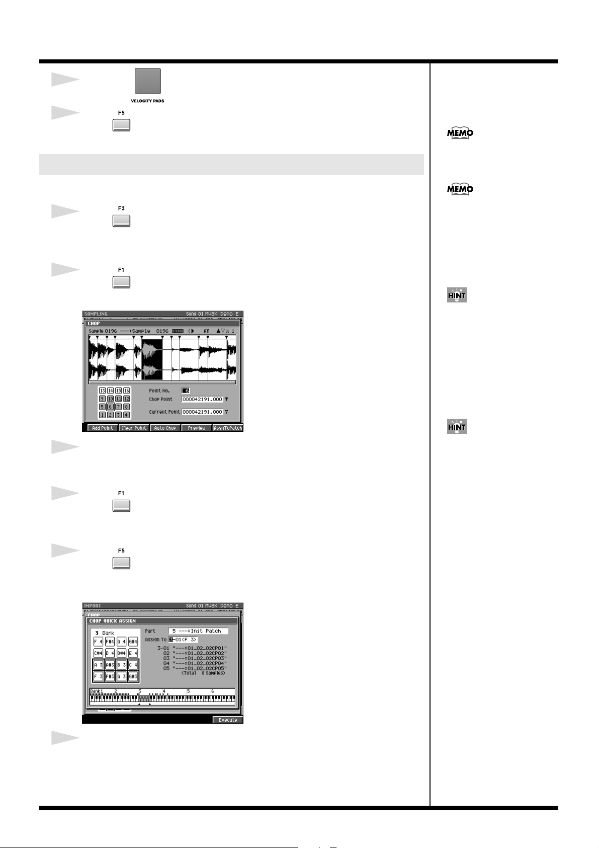
Changes in Sampling and Importing
3
Strikes the which you want to assign a sample.
4
Press (Execute).
A sample will assign to the specified velocity pad as an Audio Phrase.
Assigning a patch (partial) by chopping a sample
Here’s how you can divide a sample at the desired points and assign them to partials.
You can assign up to 95 points
(i.e., divide the sample into 96
pieces).
1
Press (Quick Assign) in “Sampling” (p. 29) step 6 or “Importing” (p. 32)
step 8.
The SELECT QUICK ASSIGN popup will appear.
2
Press (Chop).
The CHOP popup will appear.
fig.quick-assign-chop
3
Specify the Current Address parameter.
The sample will be divided at the Current Address you specify.
4
Press (Add Point).
A new dividing point with current address will be created. If you want to assign
additional dividing points, repeat step 4.
If you attempt to overwrite the
pads that has partial,
“Overwrite sure?” message
appears. If you want to
overwrite, press [F5 (YES)]. Or
press [F1 (No)] to cancel
assignment.
If you want the dividing points
to be determined
automatically according to
certain conditions, press
[F3 (Auto Chop)]. The AUTO
CHOP popup will appear. For
details on the parameters
(conditions) you can set, refer
to the AUTO CHOP popup.
The divided samples assigned
to the partial in the key follow
zero (no pitch).
42
5
Press (AsgnToPatch).
The sample will be divide at the time location(s) you specified. CHOP QUICK ASSIGN
popup will appear.
fig.patch-quick-asgn-chop
6
Specify the Part parameter (part number) and the Assign To parameter (velocity
pads) which you want to assign the divided sample(s).
Page 43

7
Press (Execute).
The divided sample(s) will assign to the specified pads as partials of the part.
Assign multiple samples as partials
Assign multiple samples you have captured on sampling or import process to the pads
as partials.
1
Press (AsgnToAPatch) when the SELECT QUICK ASSIGN popup is
displayed.
The PATCH QUICK ASSIGN (MULTIPLE) popup will appear.
Changes in Sampling and Importing
2
Specify the Part parameter which you want to assign the part number of the
instrument.
3
Specify the Assign To parameter which you want to assign the pad bank
number and pad number.
4
Press (Execute).
The sample will assign to the specified pads as audio phrase.
If you attempt to overwrite the
pads that has partial,
“Overwrite sure?” message
appears. If you want to
overwrite, press [F5 (YES)]. Or
press [F1 (No)] to cancel
assignment.
43
Page 44

Changes in Sampling and Importing
Assign multiple samples as audio phrases
Assign multiple samples you have captured on sampling or import process to the pads
as audio phrases.
1
Press (AsgnToAPhrs) when the SELECT QUICK ASSIGN popup is
displayed.
The AUDIO PHRASE QUICK ASSIGN (MULTIPLE) popup will appear.
2
Specify the Assign To parameter which you want to assign the pad bank
number and pad number.
3
Press (Execute).
The sample will assign to the specified pads as audio phrase.
If you attempt to overwrite the
pads that has audio phrase,
“Overwrite sure?” message
appears. If you want to
overwrite, press [F5 (YES)]. Or
press [F1 (No)] to cancel
assignment.
44
Page 45

Changes in Sample Edit
b
Truncating
fig.truncate-popup
Use the Truncate operation to delete
unwanted portions of a sample.
By deleting unnecessary portions (e.g.,
regions of silence at the beginning and end)
of the sample data used by a partial or
audio phrase, you can reduce the amount
of space occupied by the data, and use
memory more efficiently.
Start Point Loop Point End Point
Truncating a sample used by a partial’s SMT
1
INSTRU-
MENTS
Press .
The INSTRUMENTS screen will appear.
2
Move the cursor to the part number whose sample you want to edit.
The part number will be highlighted.
3
Press (Patch Edit).
The PATCH EDIT screen will appear.
You can’t use the Undo
function to bring back a
truncated sample.
SMT=Sample Mix Table
4
Strike of a partial that you want to truncate.
5
Press (Partial Edit).
The SAMPLE EDIT screen will appear.
6
Press (Sample).
The SAMPLE EDIT screen will appear.
7
Specify the SMT parameter to select the SMT (1–4) you want to truncate.
8
Set the Start Point parameter and End Point parameter.
The Truncate operation will apply to the region between the beginning of the sample
and Start Point, End Point and end of the sample.
9
Press (Command).
The SELECT SAMPLE EDIT COMMAND popup will appear.
you can use [SHIFT]+cursor
utton to zoom-in or zoom-out
the waveform display.
You can use [PREVIEW TO]
and [PREVIEW FROM] to
audition the sound
immediately before and after
the current point. This lets you
verify that you’ve set the start
and end points correctly.
45
Page 46
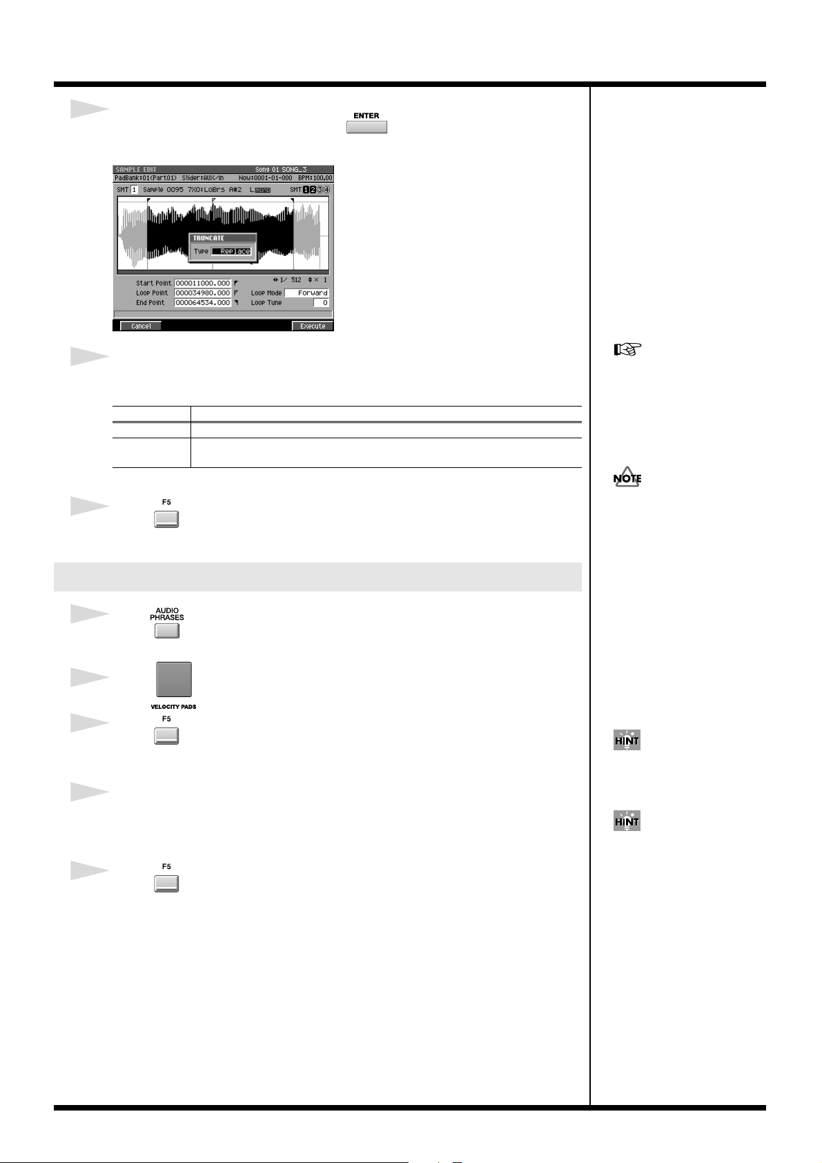
Changes in Sample Edit
b
10
Move the cursor to Truncate and press .
The TRUNCATE popup will appear.
fig.truncate-popup
11
Set the Type parameter to specify how truncate will be executed.
You can choose one of the following two types.
Type Explanation
Replace The sample being edited will be modified directly.
Duplicate
A new truncated sample will be created, and exchanged for the current
sample of the partial.
12
Press (Execute).
The Truncate operation will be executed.
Executing Truncate with Type
set to “Replace” may affect
how another partial, audio
phrase, or audio event sound.
Refer to “If a message like the
following appears.”
You can’t use the Undo
function to bring back a
truncated sample.
Truncating a sample used by an audio phrase
1
Press .
The AUDIO PHRASES screen will appear.
2
Strike of an audio phrase that you want to truncate.
3
Press (Edit).
The AUDIO PHRASE EDIT screen will appear.
4
Set the Start Point parameter and End Point parameter.
The Truncate operation will apply to the region between the beginning of the sample
and Start Point, End Point and end of the sample.
5
Press (Command).
The SELECT SAMPLE EDIT COMMAND popup will appear.
you can use [SHIFT]+cursor
utton to zoom-in or zoom-out
the waveform display.
You can use [PREVIEW TO]
and [PREVIEW FROM] to
audition the sound
immediately before and after
the current point. This lets you
verify that you’ve set the start
and end points correctly.
46
Page 47

6
Move the cursor to Truncate and press .
The TRUNCATE popup will appear.
fig.truncate-popup
Changes in Sample Edit
7
Set the Type parameter to specify how truncate will be executed.
You can choose one of the following two types.
Type Explanation
Replace The sample being edited will be modified directly.
Duplicate
A new truncated sample will be created, and exchanged for the current sample of the audio phrase.
8
Press (Execute).
The Truncate operation will be executed.
Executing Truncate with Type
set to “Replace” may affect
how another partial, audio
phrase, or audio event sound.
Refer to “If a message like the
following appears.”
You can’t use the Undo
function to bring back a
truncated sample.
47
Page 48

Changes in Sample Edit
● If a message like the following appears
fig.truncate-confirm
This message is displayed when all of the following conditions apply.
• The Truncate Type is set to “Replace.”
• The Sample to be truncated is being used by other data (i.e., other partials, audio
phrases, or audio events).
• The portion to be deleted by the Truncate function is used by other data.
In this case, you can take one of the following actions.
• Execute the Truncate operation anyway.
Press (Yes).
• Truncate the sample for only the target data.
Press (No) to cancel the operation, change the truncate Type parameter
setting to “Duplicate,” and execute the Truncate operation once again.
• To cancel the truncate procedure.
Press (No).
This message is displayed for the following reason.
(The explanation here uses the example of executing Truncate on a sample used in
common by partials A, B, and C, with the Truncate Type set to “Replace.”)
fig.truncate-example
partial A
partial B
partial C
If you truncate the sample of partial A as shown in the diagram, a portion of the
sample used by partial C will be deleted. (Partial B is not affected.)
This means that partial C will no longer sound as it did before truncation.
When you execute a Truncate operation that would affect the sound of a
partial (or other data) in this way, the MV-8000 is designed to delete the data
that is affected (partial C will be deleted).
The message displayed above is warning you that “the data whose sound is
affected by this operation will be deleted.”
If you want to truncate partial A but preserve the state of partial C, execute
Truncate with the Type set to “Duplicate.”
If you execute Truncate with
the Type set to “Duplicate,” a
new sample will be created.
This will consume more
memory.
48
Page 49

Changes in Sample Edit
Added the AUDIO PHRASE SAMPLE EDIT screen
You can now move from the AUDIO PHRASE EDIT screen to the AUDIO PHRASE
SAMPLE EDIT screen. This lets you adjust the playback point while watching a large
waveform display.
1
Press .
The AUDIO PHRASES screen will appear.
2
Strike of an audio phrase that you want to edit.
3
Press (Edit).
The AUDIO PHRASE EDIT screen will appear.
4
Press (Sample Edit).
The AUDIO PHRASE SAMPLE EDIT screen will appear.
5
Specify the Start Point, Loop Point and End Point parameters.
49
Page 50

Changes in Sample Edit
Deleting the sample along with the partial (Delete Partial)
You can delete a sample at the same time that you delete a partial.
1
INSTRU-
MENTS
Press .
The INSTRUMENTS screen will appear.
2
Use to select the part of the partial that you want to delete.
The selected part number (the current part) will be highlighted.
3
Hold down , and strike the for the partial you want to
delete.
A confirmation message of “Delete partial on Pad ##-##. Are You Sure?” will appear.
(##-## are the pad bank number and pad number.)
F button Explanation
(No)
(Assign Only)
(Yes)
● Deleting a sample that’s used by more than one partial /
audio phrase / audio event
When press [F5 (Yes)] in step3, the sample you are about to delete is used by another
partial, audio phrase, and/or audio event, the following message will appear.
fig.delete-sample-confirm
Cancels the operation (The partials and sample will remain).
Deletes the partial (the sample will remain).
Deletes the partials and sample used by that partial.
You can’t use the Undo
function to bring back a
deleted partial or sample.
50
(One or more other partials, audio phrases, and/or audio events will be lost if you
delete this sample. Are you sure you want to delete?)
F button Explanation
(No)
(Yes)
Cancels the operation (the partials and the sample will remain).
Deletes the partials and the sample used by that partial.
You can’t use the Undo
function to bring back a
deleted sample.
Page 51

Changes in Sample Edit
Deleting the sample along with the audio phrase (Delete Audio Phrase)
You can delete a sample at the same time that you delete a audio phrase.
1
Press .
The AUDIO PHRASES screen will appear.
2
Hold down , and strike the for the audio phrase you want
to delete.
A confirmation message of “Delete Audio Phrase on Pad ##-##. Are You Sure?” will
appear.
(##-## are the pad bank number and pad number.)
F button Explanation
Cancels the operation (The audio phrase and sample will
(No)
(Assign Only)
(Yes)
remain).
Deletes the audio phrase (the sample will remain).
Deletes the audio phrase and sample used by that audio phrase.
You can’t use the Undo
function to bring back a
deleted audio phrase or
sample.
● Deleting a sample that’s used by more than one partial /
audio phrase / audio event
When press [F5 (Yes)] in step2, the sample you are about to delete is used by another
partial, audio phrase, and/or audio event, the following message will appear.
fig.delete-sample-confirm
(One or more other partials, audio phrases, and/or audio events will be lost if you
delete this sample. Are you sure you want to delete?)
F button Explanation
(No)
(Yes)
Cancels the operation (the audio phrase and the sample will remain).
Deletes the audio phrase and the sample used by that audio phrase.
You can’t use the Undo
function to bring back a
deleted sample.
51
Page 52

Changes in Sample Edit
Deleting the sample along with the patch (Delete Patch)
You can delete a sample at the same time that you delete a patch.
1
INSTRU-
MENTS
Press .
The INSTRUMENTS screen will appear.
2
Use to select the part of the patch that you want to delete.
The selected part number (the current part) will be highlighted.
3
Press .
The MENU popup will appear.
4
Use to select the “Delete Patch” then press .
A confirmation message of “Delete Patch on Part ##. Are You Sure?” will appear.
(## is a part number.)
fig.delete-patch-confirm
F button Explanation
Cancels the operation
(No)
(Assign Only)
(Yes)
(The patch and sample
will remain).
Deletes the patch (the
sample will remain).
Deletes the patch and
sample used by that
patch.
You can’t use the Undo
function to bring back a
deleted patch or sample.
● Deleting a sample that’s used by more than one partial /
audio phrase / audio event
When press [F5 (Yes)] in step4, the sample you are about to delete is used by another
partial, audio phrase, and/or audio event, the following message will appear.
fig.delete-sample-confirm
(One or more other partials, audio phrases,
and/or audio events will be lost if you
delete this sample. Are you sure you want
to delete?)
F button Explanation
Cancels the operation (the
(No)
(Yes)
patch and the sample will
remain).
Deletes the patch and the
sample used by that patch.
You can’t use the Undo
function to bring back a
deleted sample.
52
Page 53

● Differences between Optimizing and Deleting Samples
Deleting samples by optimizing
The Optimize operation automatically finds samples that are not used by any song
in the current project, and deletes them.
This makes it a quick way to reduce the amount of memory being used.
However, since you cannot choose the samples that are deleted, samples that are
not assigned to any materials will be deleted unconditionally.
For example, this means that samples you might be intending to use later will also
be deleted.
Deleting samples together with material (partials, audio phrases,
patches)
If you use the Delete Partial, Delete Audio Phrase, or Delete Patch operations to
delete samples at the same time, only the samples used by those materials will be
deleted.
This means that samples not assigned to any material will not be deleted.
In addition, the MV-8000 will check whether the samples you are attempting to
delete are being used by any other song in the current project, and will display a
warning if such a sample is found.
Changes in Sample Edit
Assigning a partial to pads in a pitched scale (Set Chromatic)
You can set scales to a partial assigned on pads. Just like performance on keyboard,
you can perform partials on pads with scales.
1
INSTRU-
MENTS
Press .
The INSTRUMENTS screen will appear.
2
Use to select the part that you want to set scales to a partial.
The selected part number (the current part) will be highlighted.
3
Press (Patch Edit).
The PATCH EDIT screen will appear.
4
Press (Split).
The PATCH EDIT (SPLIT) screen will appear.
On this screen, you can assign currently selected partial to the pad within specified
instruments part.
fig.delete-sample-confirm
53
Page 54

Changes in Sample Edit
5
Select pad bank No. and pad No. where the partial (the partial you like to set
scale) is assigned under Pad parameter.
You will see the area of partial assignment to pads in Current Lower Point and Upper
Point.
6
Set the area of pads where you like to set partials with scales under New Lower
Point and Upper Point parameter.
7
Press (Set Chroma).
Within the area specified under New Lower Point and Upper Point parameter, partials
with chromatic scale will be assigned.
Partials assinged between Current Lower Point and Upper Point will be re-assigned to the
area between New Lower Point and Upper Point (So, those will be deleted from original
area).
Patials will be assigned to pads
in the pad bank that is
specified under New Lower
Point and Upper Point
parameter.
[F3 (Set Chroma)] is an additional function to [F5(Set)]. With this function, you can set partial
to pad with chromatic scale. If you set different scales on a partial on pad and set other pads
sequentially, you can perform like a keyboard.
F button Explanation
Change Pitch KF (Partial Edit SMT screen) parameter of partials to
(Set Chroma)
(Set)
[Norm (chromatic scale)] and assign partials to pads.
Not change Pitch KF (Partial Edit SMT screen) parameter of partials,
and assign partials to pads.
Press [F5 (Set)] if you like to
assign with current scale
(without setting chromatic
scale).
You can adjust the scales of
assigned partials under Coarse
and Fine parameters in the
PARTIAL EDIT screen.
You can change Pitch KF of
partials in the PARTIAL EDIT
(SMT) screen.
If you try to assign new partial
to the pad where another
partial is already assigned, the
pad assignment will be
overwritten with the new
54
Page 55

Changes in recording and editing sequences
Selecting a region quickly (Quick Region)
The Quick Region function lets you quickly select an editing region for the current
track (SEQUENCE EDIT screen) or current note (PIANO ROLL EDIT screen).
1
Press .
The SEQUENCE screen will appear.
2
Press (Seq Edit) or (PianoRoll).
When you press (Seq Edit), the SEQUENCE EDIT screen will appear. When you
press (PianoRoll), the PIANO ROLL EDIT screen will appear.
3
Move the cursor to a track (or note) that contains the events you want to regionselect, making it the current track (current note).
You can’t execute Quick region
on more than one track (note).
However, after using Quick
Region to select a region, then
press [F2 (All Track Sel)] or [F2
(All Note Sel)], you can select
that region across all tracks
(notes).
4
Move the time so that the current time intersects the events you want to regionselect.
This determines the events that will be edited.
5
Press (Quick Rgn).
The events will be highlighted and selected.
fig.quick-region
Now
Current track
Current note
Selects a data that the current track (note)
intersects the current time.
The selected region in the SEQUENCE EDIT screen
● When the current track is a MIDI track
From the beginning to the end of the current measure of the current track will be
selected (i.e., one measure).
Now
● When the current track is an Audio track
If there is an audio event at the current time in the current track, that single audio event
will be selected. The length selected will be the single audio event located at the current
time. If there is no audio events at the current time in the current track, from the
beginning to the end of the current measure will be selected.
the selected region in the PIANO ROLL EDIT screen
If there is a note event at the current time in the current note (Target), a length
corresponding to the duration of the note event will be selected.
If there is not a note event at the current time in the current note (target), a length
corresponding to the STEP TIME will be selected.
55
Page 56

Changes in recording and editing sequences
Initiate recording when a note message is received
In the RECORDING PARAMETER screen, you can now choose “Wait Note” as the
Count In setting.
If you set Count In to “Wait Note,” the MV-8000 will begin recording as soon as any of
the following actions occur.
• Receive a note message
(i.e., play a note on a keyboard or other device connected to MIDI IN)
• Strike .
• Press .
If you use Wait Note in the
audio track, you should set the
Rec Mode parameter is Event.
Step-recording for the length of an audio phrase
In the AUDIO PHRASE STEP REC screen, “Phrase” has been added as a choice for the
Step Time parameter.
If you set the Step Time to “Phrase,” the length of the recorded audio event will be the
length of the audio phrase.
56
Page 57

Changes in recording and editing sequences
Combining multiple MIDI tracks into one (Merge Tracks)
This command combines the performance data from multiple adjoining MIDI tracks
into one track. This is convenient when you have run out of MIDI tracks, or if you
recorded several drum tracks separately and want to combine them into a single track.
1
Press .
The SEQUENCE screen will appear.
2
Press .
SEQUENCE MENU popup will appear.
3
Use to move the cursor to “Merge Tracks” then press .
The MERGE TRACKS popup will appear.
fig.quick-region
Audio track data cannot be
merged.
4
Specify the parameters.
• Source From
Specify the track number of the first track you want to merge.
Range: 1–Current track–136
• Source To
Specify the track number of the end track you want to merge.
Range: 1–Current track–136
• Merge To
Specify the destination in which the merged data will be placed.
Range Explanation
New A new track will be created, and the merged data will be placed in it.
1–136 The merged data will be placed in the track whose number you specify.
• Keep Source Tracks
This specifies whether the tracks specified by Source From/To will be kept.
Range Explanation
Off
On Remain the performance data.
Delete the performance data specified from Source From track to Source To
track.
5
Press (Execute).
The Merge Track operation will be executed. The performance data of the MIDI tracks
between Source From and Source To will be combined and placed in the Merge To
track.
57
Page 58
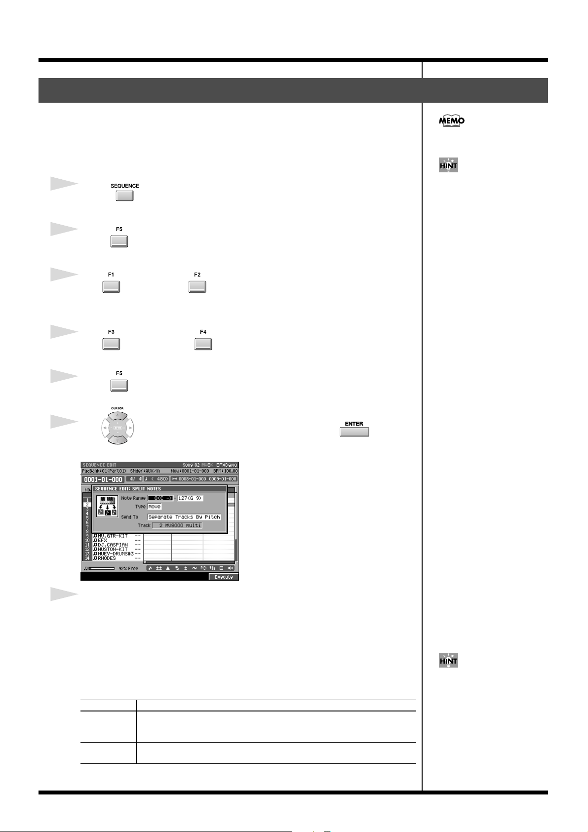
Changes in recording and editing sequences
Extracting specific note events (Split Notes)
This lets you extract only specific note events from a track, and move them to a
specified other track.
For example, if you have an entire drum performance recorded in a single track, you
can use this command to extract just the snare drum notes and place them on a
different track.
You cannot extract data from
audio tracks.
1
Press .
The SEQUENCE screen will appear.
2
Press (Seq Edit).
The SEQUENCE EDIT screen will appear.
3
Use (Track Sel) or (All Track Sel) to select the track(s) from which
you want to extract note events.
A selection symbol is displayed for the selected tracks.
4
Use (Rgn In/Out) or (Quick Rgn) to select the region of time from
which you want to extract note events.
5
Press (Command).
The SELECT SEQUENCE EDIT COMMAND popup will appear.
6
Use to move the cursor to “Split Notes” then press .
The SPLIT NOTES popup will appear.
fig.quick-region
This is a convenient way to
apply Play Quantize to only
the hi-hat.
58
7
Specify the parameters.
• Note Range
This specifies the range of note numbers that will be extracted.
Range: 0 (C -)–127 (G 9)
• Type
This specifies what will happen after the note events are extracted from the original
track.
Range Explanation
The notes specified by Note Range will be moved from the original track to
Move
Copy
the destination track. The corresponding note events will be deleted from the
original track.
The notes specified by Note Range will be copied from the original track to
the destination track. The notes of the original track will remain unchanged.
If you set the larger value at
the left-hand cursor than the
value at the right-hand cursor,
the SPLIT NOTES operation
will be executed for the note
number other than you set at
the Range parameter.
Page 59

Changes in recording and editing sequences
• Send To
This specifies how the extracted note events will be recorded.
Range Explanation
Separate
Tracks by Note
One Track
One New Track The extracted note events will be placed in a newly created track.
A separate track will be created for each note.
The extracted note events will be placed in the copy-destination track you
specify at the Track parameter.
• Track
In case of the Send To is “One Track,” this specifies the track number in which the
extracted note events will be placed.
Range: 1–Current Track–136
8
Press (Execute).
The Split Notes operation will be executed.
If you use the Send To “One
Track” setting to place the
extracted data in a track that
already contains data, the
extracted data will be
combined with the existing
data in the destination track.
If you want to separate drum
notes into individual tracks,
use the Send To “Separate
Tracks By Note” setting.
59
Page 60
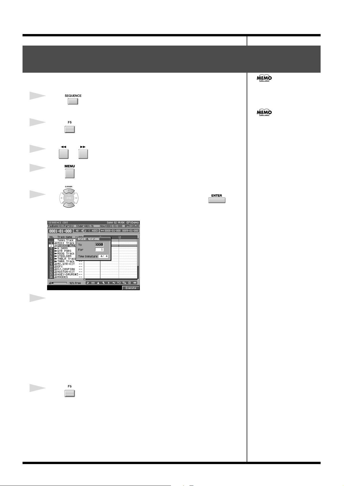
Changes in recording and editing sequences
Inserting blank measures at the specified time (Insert Measure)
Here’s how to insert blank measures at the specified measure location.
You can specify the time
1
Press .
The SEQUENCE screen will appear.
signature of the inserted
measures.
2
Press (Seq Edit).
The SEQUENCE EDIT screen will appear.
3
Use or to move the current time you want to insert blank measures.
4
Press .
SEQUENCE MENU popup will appear.
5
Use to move the cursor to “Insert Measure” then press .
The INSERT MEASURE popup will appear.
fig.quick-region
When you insert measures, the
settings of the tempo track will
change correspondingly
6
Specify the parameters.
•To
Specify the insert-destination measure number.
Range: 0001–measure number of the current time location–9999
• For
Specify the number of blank measures you want to insert.
Range: 1–9999
• Time Signature
Specify the time signature of the measures you want to insert.
Range: Same time signature as the preceding measure, 1–32 / 2, 4, 8, 16
7
Press (Execute).
The Insert Measure operation will be executed.
60
Page 61
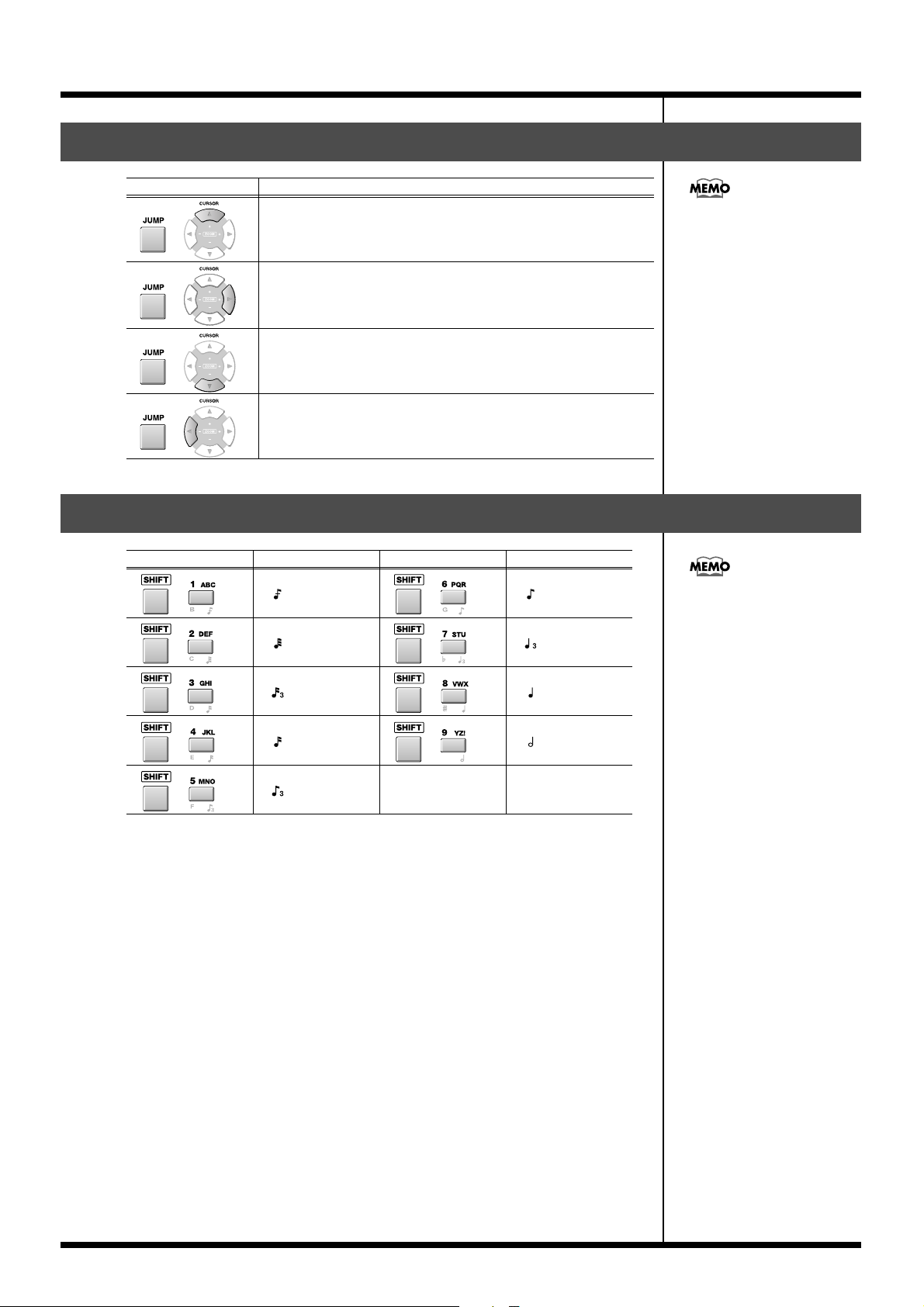
Changes in recording and editing sequences
Using shortcuts to execute editing commands
Shortcut Function
Editing command shortcuts
+
Deletes the selected event (Erase).
are valid in the SEQUENCE
EDIT screen and the PIANO
ROLL EDIT screen.
+
+
+
Moves the selected event to the current time location (Move).
Copies the selected event to the current time location (Copy&Paste).
If an audio event exists at the current time location, displays the
AUDIO EVENT PARAMETER popup (valid only in the SEQUENCE
EDIT screen.
Using shortcuts to switch the step time
Function Step Time Function Step Time
+
+
+
+
(30)
+
(60)
+
(80)
+
(120)
+
(240)
(320)
(480)
(960)
[SHIFT]+a numeric key
function is valid in the STEP
REC screen, the AUDIO
PHRASE STEP REC screen, the
SEQUENCE screen and the
SEQUENCE EDIT screen.
+
(160)
61
Page 62

Changes in Mixdown and Mastering
Mixdown
1
Press .
The MASTERING MENU screen will appear.
2
Press (Mixdown) or use to select the “MIXDOWN MODE” icon
then press .
If Mixdown mode is off, the display will ask “Enter Mixdown Mode. Are you sure?”
F-button Action
Cancels the procedure, and returns to the MASTERING MENU
(No)
(Yes)
screen.
Turns Mixdown mode on. You will
go to the SEQUENCE screen, which
will indicate “** Mixdown Mode **.”
Continue to step 3.
3
Turn to MAX.
This lets you mixdown without reducing the volume.
4
Press .
You can start the mixdown
from any time location. Simply
move the current time to that
point, and then start the
mixdown.
If Mixdown mode is on, the
display will ask “Exit
Mixdown Mode. Are you
sure?”
If you mix down without
setting the MASTER knob to
MAX, the volume will be
lower. You should leave this
knob at MAX unless you are
creating a fade-in or fade-out.
The EDIT MIXDOWN FILE NAME popup will appear.
5
Specify a filename.
A default filename is assigned automatically. You can change this if desired.
6
Press (OK).
The REC indicator (red) will blink, and the MV-8000 will be in mixdown-standby.
7
Press .
Mixdown will begin. REC indicator (red) and PLAY indicator (green) will lit.
If you operate the mixer or
effects during mixdown, your
changes will be reflected in the
mixdown data.
If you press [EXIT] in step 6,
the EDIT MIXDOWN FILE
NAME popup window will
close without entering standby
mode.
If you specified mixdown
filename is onto a
MIXDOWNTR folder that
already contains setting, “That
name already exists.
Overwrite?” message will
appear.
If you press [F1 (No)], you can
edit filename again.
If you press [F5 (Yes)], the
previous data will be
overwritten.
62
Page 63

Changes in Mixdown and Mastering
8
To stop the mixdown, press .
Mixdown will end, and the mixdown file will be saved in the MIXDOWNTR folder
([REC] and [PLAY] indicator will be dark).
“Mixdown finished. Go to Mastering?” message will appear.
F-button Action
(No)
(Exit Mixdown)
(Yes)
Mastering
1
Press .
The MASTERING MENU screen will appear.
2
Press (Mastering). Alternatively, select the MASTERING icon and press
.
The SELECT AUDIO FILE / SELECT MASTERING SOURCE popup will appear.
3
Move the cursor to the file that you want to master, and press (Execute).
The MASTERING screen will appear.
You will return to the SEQUENCE screen.
The Mixdown Mode will turn off, the SEQUENCE screen
will appear.
You will go to the MASTERING screen.
If you mastering without
setting the MASTER knob to
MAX, the volume will be
lower. You should leave this
knob at MAX unless you are
creating a fade-in or fade-out.
4
Turn to MAX.
This lets you mastering without reducing the volume.
63
Page 64

Changes in Mixdown and Mastering
5
Press .
The EDIT MASTERING FILE NAME popup will appear.
6
Specify a filename.
A default filename is assigned automatically. You can change this if desired.
7
Press (OK).
The REC indicator (red) will blink, and the MV-8000 will be in mastering-standby.
If you press [EXIT] in step 7,
the EDIT MASTERING FILE
NAME popup window will
close without entering standby
mode.
If you specified mixdown
filename is onto a MASTERTR
folder that already contains
setting, “That name already
exists. Overwrite?” message
will appear.
If you press [F1 (No)], you can
edit filename again.
If you press [F5 (Yes)], the
previous data will be
overwritten.
8
Press .
Mastering will begin you selected file in step 3. REC indicator (red) and PLAY
indicator (green) will lit.
9
To stop the mastering, press .
Mastering will end, and the mastering file will be saved in the MASTERTR folder
([REC] and [PLAY] indicator will be dark).
“Mixdown finished. Go to CD Burning?” message will appear.
F-button Action
(No)
(Yes)
You will return to the MASTERING screen.
You will go to the CUE SHEET screen.
If you operate the mastering
effects during mastering, your
changes will reflected in the
mastering data.
If playing reaches to the end of
selected file in step3, mastering
will stop automatically.
64
Page 65
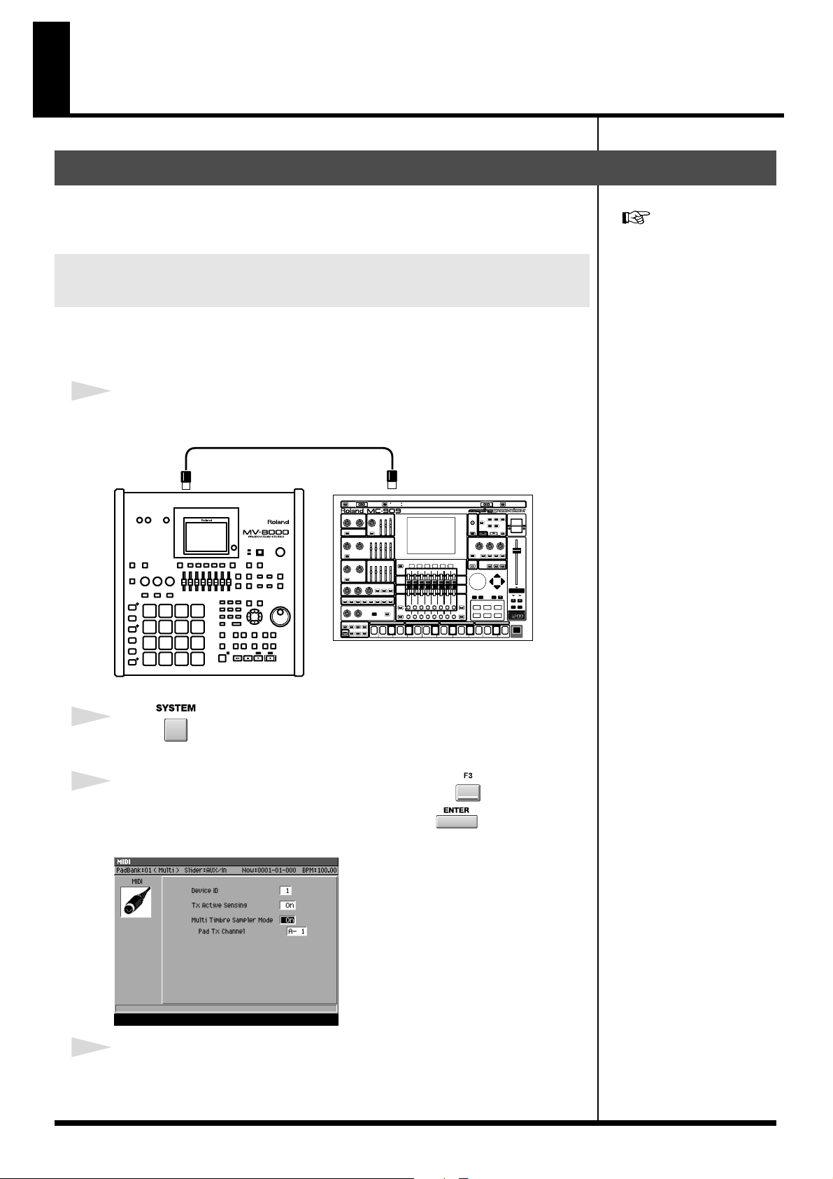
Using the MV-8000 with external devices
Using the MV-8000 in Multitimbre Sampler Mode
In Multi Timbre Sampler mode, the MV-8000’s instruments function as a multi-timbral
sound module. And the performance data from the velocity pads is transmitted as
MIDI messages (MIDI OUT A/B, R-BUS).
Playing the MV-8000 from an externallyconnected sequencer
Here’s how the MV-8000 can function as a multi-timbral sound module receiving
multiple channels of MIDI performance data from an externally-connected MIDI
sequencer.
1
Connect the MV-8000’s MIDI IN connector to your MIDI sequencer’s MIDI OUT.
fig.mv8000-midi-909
MIDI Cable
MIDI OUTMIDI IN
Certain limitations apply when
Multi Timbre Sampler mode is
on. For details, refer to
“Performance Data Flow and
Limitations in Multi Timbre
Sampler Mode” (p. 68).
Sequencer
MV-8000
2
Press .
The SYSTEM MENU screen will appear.
3
With the cursor located in the upper row of icons, press (MIDI).
Alternatively, you can select the MIDI icon and press .
The MIDI screen will appear.
fig.midi-screen
4
Turn the Multi Timbre Sampler Mode parameter On in the MIDI screen.
This setting lets the MV-8000 receive performance data from your external MIDI
sequencer, so that the MV-8000’s instruments will play.
65
Page 66

Using the MV-8000 with external devices
5
Press .
The SEQUENCE screen will appear.
6
Start playback on your external sequencer.
The MV-8000’s instruments will play the performance data being sent from your
external MIDI sequencer.
Multi Timbre Sampler Mode is
available only while the
following screens are
displayed.
• SEQUENCE screen
• INSTRUMENTS screen
• EFFECTS screen
• MIXER screen
Recording your velocity pad performance on an externally-connected sequencer
If you turn Multi Timbre Sampler Mode on, your playing on the MV-8000’s velocity
pads will be transmitted as MIDI messages. This means you can record your
performance on an externally-connected sequencer.
1
Connect the MV-8000’s MIDI OUT connector to your MIDI sequencer’s MIDI IN.
fig.mv8000-midiin-909
MIDI Cable
You can’t record performance
data on the MV-8000’s own
internal sequencer while Multi
Timbre Sampler Mode is on.
MIDI INMIDI OUT
MV-8000
2
Press .
SYSTEM screen will appear.
3
With the cursor located in the upper row of icons, press (MIDI).
Alternatively, you can select the MIDI icon and press .
The MIDI screen will appear.
fig.midi-screen
Sequencer
66
Page 67

Using the MV-8000 with external devices
4
Turn the Multi Timbre Sampler Mode parameter On in the MIDI screen.
With this setting, your playing on the velocity pads will be transmitted from the MIDI
OUT connector.
5
Set the Pad Tx Channel parameter.
This specifies the MIDI OUT connector and channel used to transmit your playing on
the velocity pads.
Range Explanation
A- 1 Transmit a MIDI data from MIDI OUT A, channel 1.
: :
A-16 Transmit a MIDI data from MIDI OUT A, channel 16.
B- 1 Transmit a MIDI data from MIDI OUT B, channel 1.
: :
B-16 Transmit a MIDI data from MIDI OUT B, channel 16.
R- 1 Transmit a MIDI data from R-BUS, channel 1.
: :
R-16 Transmit a MIDI data from R-BUS, channel 16.
6
Press .
SEQUENCE screen will appear.
7
Start recording on your external sequencer, and play the velocity pads.
Your velocity pad performance will be recorded on the external sequencer.
You can set the Pad Tx
Channel parameter only if
Multi Timbre Sampler Mode is
on.
Value R- 1–R-16 is displayed
when MV8-OP1 is installed.
Your playing on the velocity
pads can be transmitted as
MIDI data while the following
screens are displayed.
• SEQUENCE screen
• EFFECTS screen
• MIXER screen
67
Page 68

Using the MV-8000 with external devices
b
● Performance Data Flow and Limitations in Multi Timbre
Sampler Mode
As shown below, the performance data flow differs depending on the Multi
Timbre Sampler Mode setting in the MIDI screen.
When Off (normal)
fig.multitimbre-off
MIDI OUT A/B/R-BUS
MV-8000
Velocity Pads
MIDI IN
Sequencer Instr uments
Performance data received at MIDI IN or from the velocity pads is sent to MIDI
OUT and/or plays the MV-8000’s instruments according to the Output Assign
parameter and Output Assign MIDI parameter of the current track.
When On
The MV-8000 will operate in the following way.
fig.multitimbre-on
MIDI IN
MV-8000
MIDI Ch. 1
~
MIDI Ch. 16
Velocity Pads
Sequencer Instr uments
• Operate as a multi-timbral sound module
Performance data received at MIDI IN is sent to the instruments. Instrument part
1 receives MIDI channel 1, instrument part 2 receives MIDI channel 2, etc., ... and
instrument part 16 receives MIDI channel 16.
MIDI OUT A/B/R-BUS
(1~16)
• Transmit performance data from the velocity pads as MIDI messages
The performance data from the velocity pads is transmitted from the MIDI output
(MIDI OUT A/B connector, R-BUS connector) and channel specified by the Pad Tx
Channel parameter in the MIDI screen.
● Limitations when Multi Timbre Sampler Mode is On
• Performance data from the velocity pads cannot be sent to the internal sound
The correspoindence between
the incoming MIDI channels
and the instrument part played
y each channel is fixed. You
cannot change this
correspondence.
generator.
• Performance data cannot be recorded on the MV-8000’s internal sequencer.
• Multi Timbre Sampler Mode is available only while the following screens are
displayed.
•SEQUENCE screen
•INSTRUMENTS screen (performance data from the velocity pads is not transmitted)
•EFFECTS screen
•MIXER screen
68
Page 69

Using the MV-8000 with external devices
Synchronized operation with external devices (Slave)
Additional parameters in the SYNC screen
Sync Mode parameter and Error Level parameter have been added to the SYNC screen.
fig.sync-screen
1. Sync Mode
This specifies the mode of operation when synchronizing an external device and the
MV-8000.
Range Explanation
Master The MV-8000 will operate using its internal clock (Master).
Slave-MIDI (MIDI)
Slave-MIDI (R-BUS)
Slave-MTC (MIDI)
Slave-MTC (R-BUS)
Remote (MIDI)
Remote (R-BUS)
The MV-8000 will receive MIDI Clock messages via its MIDI IN connector, and operate as a slave.
The MV-8000 will receive MIDI Clock messages via its R-BUS connector, and operate as a slave.
The MV-8000 will receive MTC messages via its MIDI IN connector,
and operate as a slave.
The MV-8000 will receive MTC messages via its R-BUS connector,
and operate as a slave.
The MV-8000 will receive Start, Stop, and Continue messages via its
MIDI IN connector for remote control.
The MV-8000 will receive Start, Stop, and Continue messages via its
R-BUS connector for remote control.
2. Error Level
Range: 0–5–10 (the checking interval will be longer for larger values)
This specifies the interval at which the MTC reception status is checked when Sync
Mode is set to Slave-MTC (MIDI) or Slave-MTC (R-BUS).
The MV-8000 monitors the
reception status, and will halt
synchronized operation if it
detects that a communication
problem has occurred. Higher
values make the MV-8000
more patient with problems in
the time code, giving it more
time to recover before
canceling synchronization.
69
Page 70

Using the MV-8000 with external devices
Added the R-BUS screen.
This screen lets you make R-BUS settings when the MV8-OP1 (sold separately) is
installed.
fig.sync-screen.eps
The screen contains the following parameters.
1. Word Clock
This setting specifies the word clock that the MV-8000 will use when digital audio is
being transferred over an R-BUS connection between an external device and the
MV-8000.
Setting Explanation
Internal The MV-8000 will use its own internal clock.
External The MV-8000 will use the clock from the external device connected via R-BUS.
The Word Clock parameter
was located in the GLOBAL
screen.
2. Message Type
This specifies the type of messages that will be used for communication between
R-BUS devices when the MV-8000 is connected to an external device via R-BUS.
R-BUS device connected
to the MV8-OP1
VS-series unit (or similar)
with an R-BUS connector
MV-8000
DIF-AT24
Setting Explanation
Use this setting for transferring digital audio via
R-BUS
MIDI
R-BUS, or when using MMC or MTC
synchronization between R-BUS devices.
Use this setting if the DIF-AT24 (sold separately)
is connected to the MV8-OP1 and you’re using
the MIDI IN/OUT connectors of the DIF-AT24,
or when you’re connecting two MV-8000 units.
If the DIF-AT24 is connected
and you’re using the MIDI
OUT connector of the
DIF-AT24, set Message Type to
“MIDI.” With a setting other
than “MIDI,” the MIDI device
connected to the DIF-AT24’s
MIDI OUT connector will not
operate correctly.
70
Page 71

Using the MV-8000 with external devices
Receive and synchronize to MIDI Clock
MIDI Clock messages from an externally connected sequencer or recorder (“master
device”) can be received by the MV-8000, causing the MV-8000 to operate in
synchronization as a slave device.
The example given below is a setup in which a sequencer is the master device, and the
MV-8000 receives MIDI Clock messages at its MIDI IN.
1
Connect your sequencer to the MV-8000.
fig.MV-MIDI-909.e
MIDI Cable
MIDI Clock
MIDI OUTMIDI IN
When the MV-8000 is
operating as a synchronization
slave, the synchronization
signals can be received
through either the MV-8000’s
MIDI IN connector or the
MIDI IN connector of the
DIF-AT24. However, you must
set the Sync Mode (p. 69) to
specify the connector through
which the synchronization
signals are to be received.
Sequencer
MV-8000
2
Press .
The SONG SETUP MENU screen will appear.
3
With the cursor located in the upper row of icons, press. Alternatively, select
the SYNC icon and press.
The SYNC screen will appear.
fig.sync-screen.eps
4
Set the synchronization parameters.
Here you will set parameters to specify how MIDI Clock synchronization will occur.
Refer to the table below, and make the appropriate settings on the MV-8000 and on the
externally connected master device (the sequencer or recorder that is transmitting the
synchronization signals). For details on how to make settings on your master device,
refer to its owner’s manual.
For an explanation of the other
parameters, refer to the
MV-8000 Owner’s Manual
SYNC screen.
Parameter Setting Settings on the externally connected master
device
Sync Mode Slave-MIDI (MIDI)
Set the device so that it will transmit MIDI Clock
messages (Master).
When synchronized as a MIDI
Clock slave, “Wait Note” of the
Count In setting is not
available.
71
Page 72

Using the MV-8000 with external devices
5
Play back the master device.
Press the PLAY button on the master device; the MV-8000 will begin running in
synchronization.
Receive and synchronize to MTC
MTC messages from an externally connected sequencer or recorder (“master device”)
can be received by the MV-8000, causing the MV-8000 to operate in synchronization as
a slave device.
The example given below is a setup in which a recorder is the master device, and the
MV-8000 receives MTC messages at its MIDI IN.
1
Connect your sequencer or recorder to the MV-8000.
fig.MV-clock-2400CD.e
MIDI Cable
MTC/MMC
MIDI OUTMIDI IN
MV-8000
Recorder
2
Press .
The SONG SETUP MENU screen will appear.
3
With the cursor located in the upper row of icons, press. Alternatively, select
the SYNC icon and press.
The SYNC screen will appear.
fig.sync-screen.eps
The example here also shows
how to make settings to use
MMC remote control from the
externally connected device.
MTC=MIDI Time Code
MMC=MIDI Machine Control
When the MV-8000 is
operating as a synchronization
slave, the synchronization
signals can be received
through either the MV-8000’s
MIDI IN connector or the
MIDI IN connector of the DIF-
AT24. However, you must set
the Sync Mode (p. 69) to
specify the connector through
which the synchronization
signals are to be received.
During synchronized playback
as an MTC slave, there may be
cases in which a track
containing a long audio event
drifts out of playback
synchronization with other
tracks. This occurs because
MTC synchronization is not
able to adjust the playback
speed of an audio event, and is
not a malfunction.
72
When synchronized as a MTC
slave, loop playback and
count-in recording are not
available.
Page 73
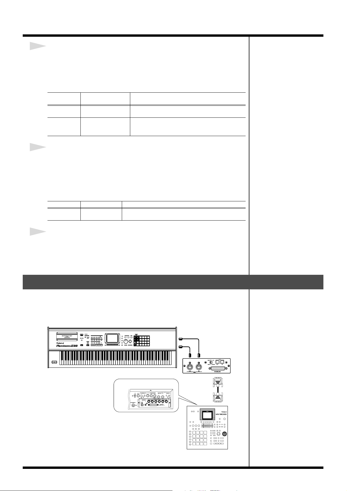
Using the MV-8000 with external devices
4
Set the synchronization parameters.
Here you will set parameters to specify how MTC synchronization will occur. Refer to
the table below, and make the appropriate settings on the MV-8000 and on the
externally connected master device (the sequencer or recorder that is transmitting the
synchronization signals). For details on how to make settings on your master device,
refer to its owner’s manual.
Parameter Setting Settings on the externally connected master
device
Sync Mode Slave-MTC (MIDI)
MTC Frame
Rate
Same as the frame
rate setting of the
master device.
Set the device so that it will transmit MTC messages
(Master).
For details on how to make settings on your master
device, refer to its owner’s manual.
5
Set the MMC parameters.
Here you will make settings to allow MMC remote control from the externally
connected device.
Refer to the table below, and make the appropriate settings on the MV-8000 and on the
externally connected master device (the sequencer or recorder that is transmitting the
synchronization signals). For details on how to make settings on your master device,
refer to its owner’s manual.
Parameter Setting Settings on the externally connected master device
MMC Mode Slave (MIDI)
Set the device so that it will transmit MMC messages
(Master).
6
Play back the master device.
Press the PLAY button on the master device; MMC messages will be transmitted to the
MV-8000, and the MV-8000 will begin running. Then MTC messages will be
transmitted from the master device, causing the MV-8000 to synchronize with the MTC
data.
Use the MIDI IN connector of the DIF-AT24
You can now use the MIDI IN connector of the DIF-AT24 (sold separately) to input
MIDI data into the MV-8000.
You can add an additional MIDI IN/OUT connector by connecting the DIF-AT24.
fig.MV-clock-2400CD.e
MIDI keyboard
MIDI OUT
MV8-OP1
MIDI IN
(Audio I/O Expansion)
MIDI
OUT
MIDI
MIDI
IN
DIF-AT24
R-BUS
MV-8000
R-BUS
73
Page 74

Changes in the others
b
Directly selecting a pad bank ([PAD BANKS]+Pad 1–16)
You can switch pad banks by directly specifying a number.
1
Hold down , and strike (1–16) that corresponds to the
desired pad bank.
The pad bank will switch. You can switch between pad banks 1–6 for instruments, or
between pad banks 1–16 for audio phrases.
Using the velocity pads to switch Track Mute and Solo
Here’s how to use the velocity pads to switch Mute (silenced) and Solo settings on/off
for a track.
1
Hold down , and press .
The TRACK MUTE screen will appear.
fig.trackmute-screen.eps
You can’t use this method to
switch to audio phrase pad
anks 17–32. Press [PAD
BANKS] and use the VALUE
dial or the numeric keys to
specify the bank number.
2
Press (Mute) to switch the mute setting of a track, or press (Solo) to
switch the solo setting.
The TRACK MUTE screen will appear if you press [F1 (Mute)]. The TRACK SOLO
screen will appear if you press [F2 (Solo)].
3
Use value dial or / to set the Track Bank parameter.
Track Banks divide tracks 1–136 into groups of sixteen tracks. Select the track bank
containing the tracks you want to mute or solo.
4
Strike .
The track corresponding to the velocity pad you struck will be muted or soloed. Muted
tracks are indicated by the “MUTE” icon, and the pad will be displayed in dark gray.
Soloed tracks are indicated by the “SOLO” icon, and the pad is displayed in white.
fig.trackmute-screen.eps
MUTE Icon SOLO Icon Normal
The velocity pads of pad banks
1–9 are displayed in miniature
at the right of the Track Bank
parameter to indicate the
current mute and solo settings.
74
Page 75
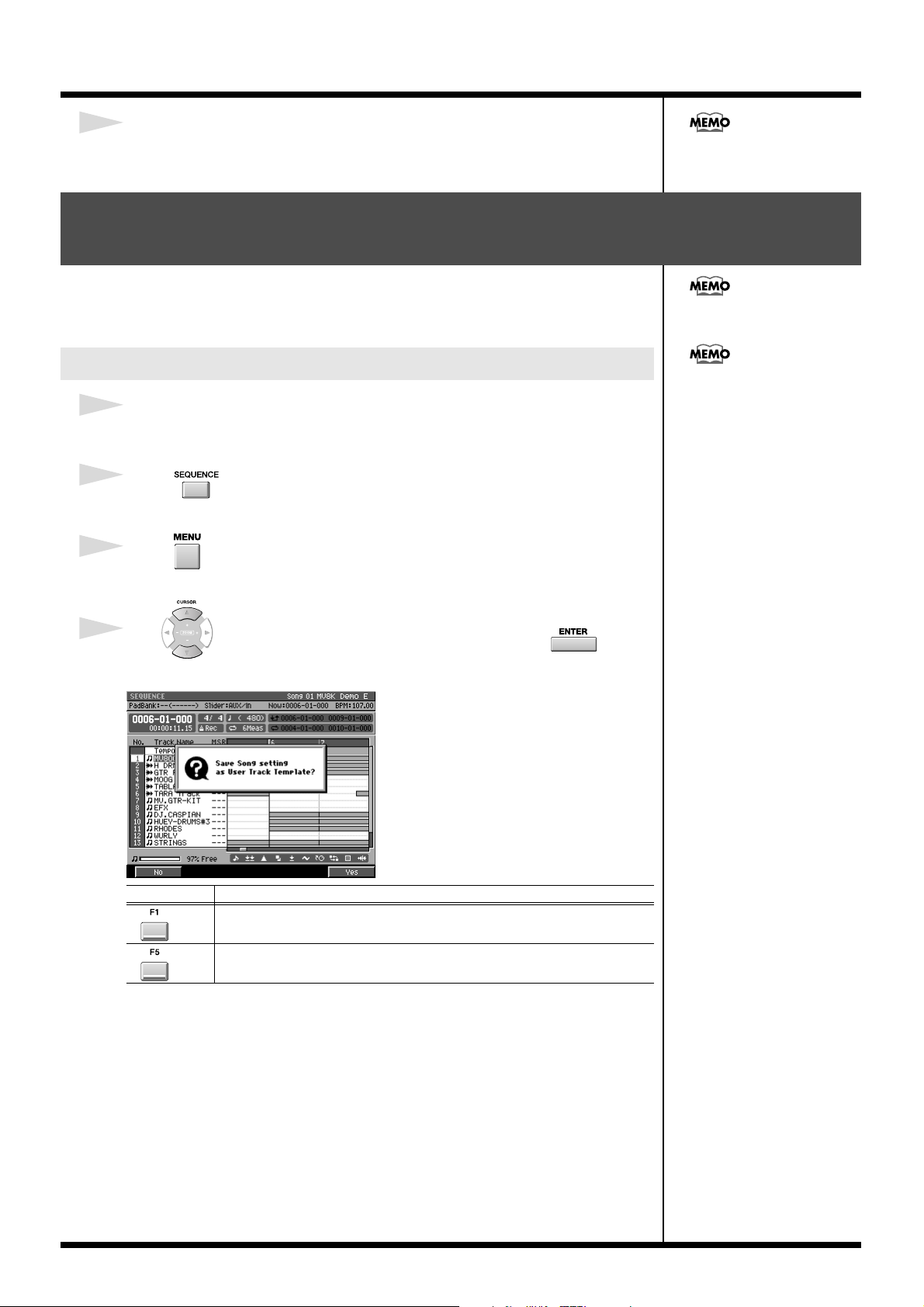
Changes in the others
b
5
Press EXIT to exit the TRACK MUTE screen or TRACK SOLO screen.
The SEQUENCE screen will appear.
You cannot record the
operation of muting and
soloing tracks to the sequencer.
Starting a new song with your favorite settings (User Track Template)
Your favorite settings such as the track structure or loop settings of a song can be stored
on the hard disk as a “template” for recall any time you want to start creating a song
with that structure.
Only one user track template
can be stored.
Saving a User Track Template
1
For the current song, create the structure that you want to save as a user track
template.
2
Press .
The SEQUENCE screen will appear.
3
Press .
The SEQUENCE MENU popup will appear.
4
Use to select to “Save As User Template” then press .
“Save Song setting as User Track Template?” message will appear.
fig.track-mute-screen
Since the user track template is
stored on the hard disk, it will
e lost if you initialize (format)
the hard disk.
F button Explanation
The user track template will not be saved. The SEQUENCE screen will
(No)
(Yes)
appear.
Things such as the track settings for the current song will be saved on the hard
disk as a user track template.
75
Page 76

Changes in the others
Using a user track template to create a song
1
Press .
The SONG SETUP MENU screen will appear.
2
With the cursor located in the upper row of icons, press (Create New).
Alternatively, you can select the CREATE NEW SONG icon and press .
The CREATE NEW SONG screen will appear.
3
Set the Track Layout parameter to “User Template.”
4
Press (Execute).
A new song will be created according to the settings saved in the user track template.
Saving a song in SMF format (Save As SMF)
Here’s how to save the current song in SMF (Standard MIDI File) format 1.
This allows a song created on the MV-8000 to be played or edited by sequencer or other
software on a computer.
SMF=Standard MIDI File
1
Make the current song the song you want to convert to SMF format.
Select the Song you want to convert to SMF format, as the current song.
2
Press .
The SONG SETUP MENU screen will appear.
3
With the cursor located in the lower row of icons, press (SaveAsSMF).
Alternatively, you can select the SAVE AS SMF icon and press .
The SAVE SONG AS SMF screen will appear.
fig.savesmf-screen.eps
4
Use to select a folder you want to save the SMF.
A folder will be highlighted.
5
Press (Execute).
The SMF will be saved to specified folder and filename.
If you press [F4 (Make
Folder)], the EDIT FOLDER
NAME popup will appear.
Where you can create a new
folder inside the current folder.
If you press [F1 (Name)], the
EDIT SMF FILE NAME popup
will appear. Where you can
edit the name of the saved as
SMF.
76
Page 77
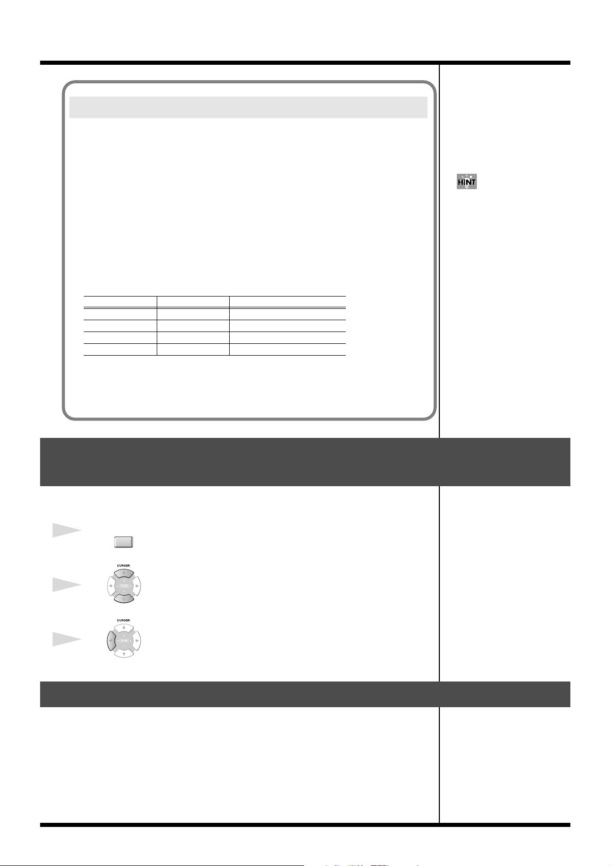
Note regarding saving to SMF
Several limitations apply when you save a song in SMF format.
• Only the current song can be converted
If you want to convert another song to SMF, you will have to switch the current
song.
• The save destination is limited to the hard disk.
You cannot save the resulting SMF data directly to floppy disk or CD-R/RW disc.
• The data is saved in SMF Format 1.
You cannot save data in SMF Format 0.
• Audio track data cannot be converted to SMF.
• MIDI channels assigned to the SMF-converted data are determined by the Output
Assign parameter and MIDI parameter for each track of the song.
MIDI channels are assigned as follows.
Output Assign (MIDI) Assigned MIDI channel
Off Off 1
1 A- 1, B- 1, R- 1 1
: : :
16 A- 16, B-16, R-16 16
Changes in the others
You can copy the saved SMF
from the hard disk to floppy
disk in the FILE UTILITY
screen. Also, you can transfer
the saved SMF to the computer
in the USB screen.
The Output Assign parameter value takes priority when assigning MIDI channels.
For example, if Output Assign is 2 and MIDI Output is A-5, channel 2 will be assigned.
However, if Output Assign is Off and MIDI Output is A-5, channel 5 will be assigned.
Viewing the PATCH LIBRARY popup in the INSTRUMENTS screen
In the INSTRUMENTS screen, simply moving the cursor to the Patch column will
display the PATCH LIBRARY popup window.
INSTRU-
1
MENTS
Press .
The INSTRUMENTS screen will appear.
2
Use to select a part you want to select the patch.
A part will be highlighted and switch the current part.
3
Use to move the cursor to the Patch column.
The PATCH LIBRARY popup will appear.
Copy or move entire folders
When using the following commands in the FILE UTILITY screen, you can now
perform operations on entire folders.
The procedure is the same as when performing the operation on an individual file.
• Copy
• Move
77
Page 78

Changes in the others
Changes in MIDI Filter parameter
Parameter Before After
PC On Off
Bank On Off
Changes in GLOBAL screen
Prevent the hard disk from being formatted (HD Format Protect parameter)
The HD Format Protect parameter lets you allow or prevent formatting of the hard
disk. When you turn on the power of MV-8000, this will automatically be turned On.
If the HD Format Protect parameter is On, it will not be possible to format the hard
disk. If you want to format the hard disk, turn HD Format Protect to the “Off” setting.
1
Press .
The SYSTEM MENU screen will appear.
2
Press (Global).
The GLOBAL screen will appear.
3
Sets the HD Format Protect parameters.
HD Format
Protect
Off
On
If you attempt to format the hard disk when the HD Format Protect parameter is On,
a message of “Can’t Format the Hard Disk. HD Format Protect is On.” will appear.
Explanation
You will be able to format the hard disk. If you want to format the hard disk,
select the “Off” setting.
You will not be able to format the hard disk. Normally, you should leave this
at the “On” setting.
Adjusting the volume of the entire sampler
You can adjust the playback volume of the entire sampler at the “Sampler Output
Gain” parameter. Adjust the parameter when you feel that the playback volume of
sampler is insufficient in spite of having adjust the level of partials and audio phrases.
1
Press .
The SYSTEM MENU screen will appear.
2
Press (Global).
The GLOBAL screen will appear.
3
Sets the Sampler Output Gain parameter.
Range: -12, -9, -6, -3, 0 (dB)
The playback volume of the
sampler is set lower than the
listening volume of sampling
on the MV-8000, beforehand,
to prevent the sound causing
distortion by the polyphony
and the setting of the filter on
the sampler.
78
Page 79

Memo
79
Page 80

* Microsoft and Windows are registered trademarks of Microsoft Corporation.
* Windows® is known officially as: “Microsoft® Windows® operating system.”
* Apple and Macintosh are registered trademark of Apple Computer, Inc.
* MacOS is a trademark of Apple Computer, Inc.
* The Akai MPC2000, MPC2000XL, S1000 and S3000 are a product manufactured by Akai Professional M.I. Corporation.
* All product names mentioned in this document are trademarks or registered trademarks of their respective owners.
03674856 ’04-5-1N
 Loading...