

Page 1
MT-300 Jan. 1999
SERVICE NOTES
First Edition
MUSIC PL AYER
TABLE OF CONTENTS Page
PANEL LAYOUT ............................................................................................... 1
PANEL LAYOUT PARTS LIST ............................................................................................... 1
SPECIFICATIONS ............................................................................................... 2
EXPLODED VIEW ............................................................................................... 3
WIRING DIAGRAM ............................................................................................... 4
PARTS LIST ............................................................................................... 5
HOW TO UPDATE THE FLASH MEMORY ............................................................................................... 7
TEST MODE ............................................................................................... 7
BLOCK DIAGRAM ............................................................................................... 10
CIRCUIT BOARD (MAIN) ............................................................................................... 11
CIRCUIT DIAGRAM (MAIN) ............................................................................................... 12
CIRCUIT BOARD (ANALOG) ............................................................................................... 13
CIRCUIT DIAGRAM (ANALOG) ............................................................................................... 14
CIRCUIT BOARD (PANEL) ............................................................................................... 15
CIRCUIT DIAGRAM (PANEL) ............................................................................................... 16
目次
パネル配置図
パネル配置図パーツリスト
主な仕様
分解図
ワイヤリング配線図
パーツリスト
フラッシュメモリーのバージョンアップの方法
テストモード
ブロック図
基板図(MAIN)
回路図(MAIN)
基板図(ANALOG)
回路図(ANALOG)
基板図(PANEL)
回路図(PANEL)
Issued by RJA
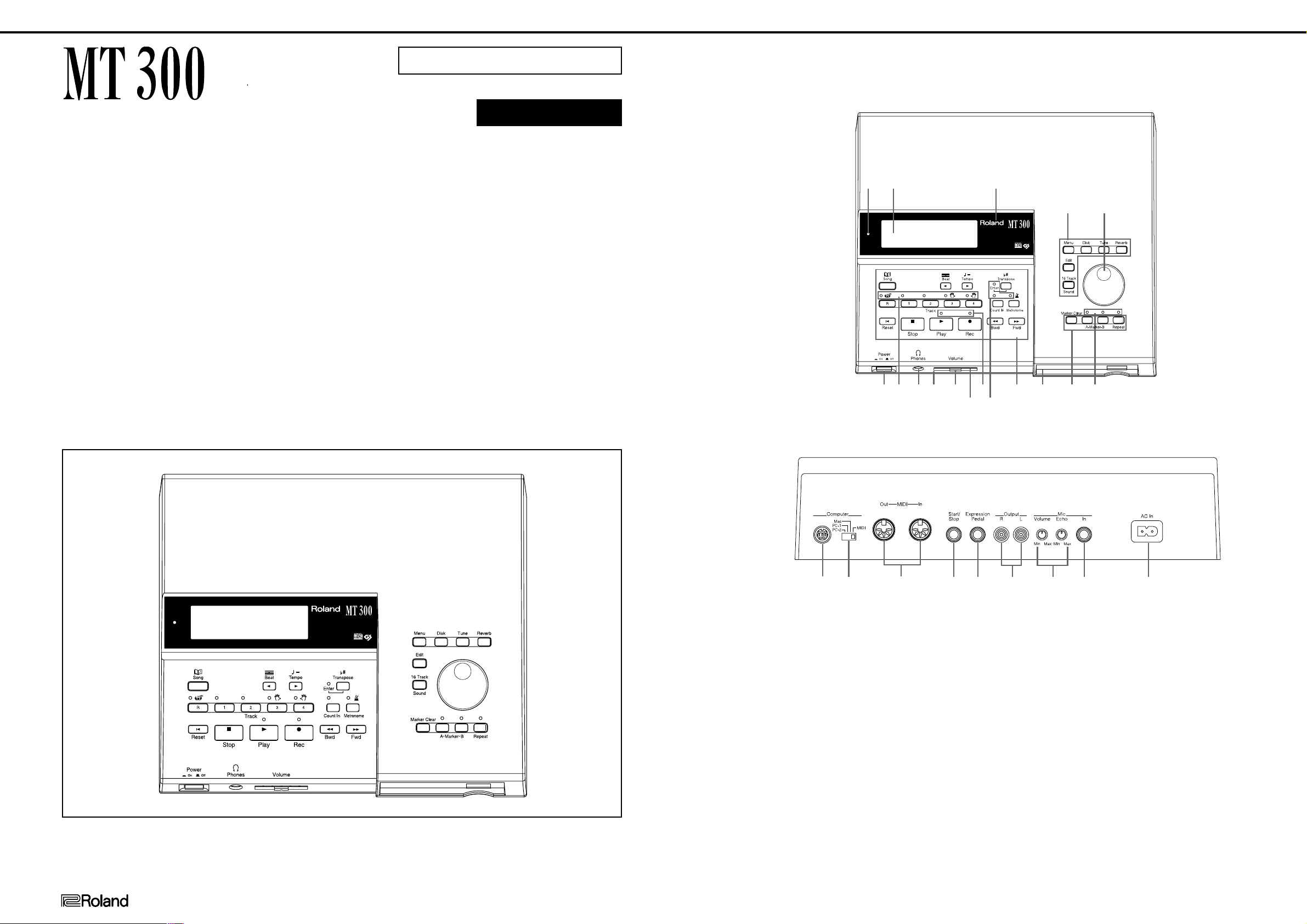
PANEL LAYOUT
FRONT VIEW
REAR VIEW
/正面図
/背面図
/パネル配置図
12345678910111213 14 15 16
!1
!2!0o
!3
yu i
ewq
MUSIC PLAYER
!4 !5 !6 !7
r
t
12345678910111213 14 15 16
MUSIC PLAYER
Copyright © 1999 by ROLAND CORPORATION
All rights reserved. No part of this publication may be reproduced in any form without the written permission of ROLAND CORPORATION.
本書の一部、もくしは全部を無断で複写・転載することを禁じます。
17059953
Printed in Japan AA00 (DP) 1
!8 !9 @0 @1 @2 @3 @4 @5 @6
PANEL LAYOUT PARTS LIST
No Part Code Part Name Description
q 01121689 LED (RED/GREEN) SPR-325MVWT31
w 71013990 LCD UNIT
e 01676245 DISPLAY COVER
r 01561434 RUBBER SW C
t 22485303 DR-KNOB L BLK 248-303
01013223 POTENTIOME EVQ VEM F01 24B
y 22495626 F S-BUTTON 249-626
01453245 PUSH SWITCH SDDLB1-B2-D-2 TV-5
u 01561445 LED LENS LENS A
i 00894001 JACK 3.5MM YKB21-5142
o 01676256 POT DUST COVER
!0 22485298 I S-KNOB S D 248-298
!1 01011645 POTENTIOME RS30H12AD 50KBX2 30MM
!2 01561467 LED LENS LENS C
/パネル配置図パーツリスト
No Part Code Part Name Description
!3 01561456 LED LENS LENS B
!4 01344923 RUBBER SW A
!5 01788045 FDD UNIT MF355F-3252MG(REV.F)
!6 01561423 RUBBER SW B
!7 01561478 LED LENS LENS D
!8 13429911 JACK (RS422 TCS7927-28-401
!9 00899223 SLIDE SWITC SSSF124-S06N1
@0 13429676 MIDI CONNEC YKF51-5048
@1 13449283 JACK 6.5MM HLJ7101-01-3010
@2 13449284 JACK 6.5MM HLJ7001-01-3010
@3 00451445 JACK YKC21-3040
@4 13279884 POTENTIOME RK09K1110 10KB
@5 13449252 JACK(STEREO 6.5MM YKB21-5006
@6 23425740 AC INLET INL-8 10A/125V 2P PO
1
Page 2

MT-300 Jan. 1999
SPECIFICATIONS
MT300s : Music Player
<Sound Generator>
Conforms to General MIDI System and GS Format
● Max.Polyphony
64 voices
● Tones
369 variations (including 8 drum sets, 1 SFX set)
● Master Tuning
415.3 Hz--466.2 Hz (0.1 Hz Steps)
● Transpose
Playback Transpose (-24--+24 Half-steps)
● Effects
Reverb (8 types), Chorus (8 Types)
<Composer>
● Metronome
Beat: 2/2, 0/4, 2/4, 3/4, 4/4, 5/4, 6/4, 7/4, 3/8, 6/8, 9/8, 12/8
Volume: 10 levels
Metronome Pattern: 11 patterns
Sounds: 4 types
● Tracks
5/16 tracks
● Song
1 song
● Note Storage
Approx. 30,000 notes
● Tempo
Quarter note = 20--250
● Resolution
120 ticks per quarter note
● Recording Method
Realtime (Replace, Mix, Auto PunchIn, Manual PunchIn, Loop, Tempo)
Beat Map
● Edit
Copy, Quantize, Delete, Insert, Erase
Transpose, Part Exchange, Note Edit
PC Edit
● Rhythm Pattern
30 types
● Control
Song Select, Reset, Stop, Play, Rec, Bwd, Fwd, All Song Play
Track Select, Count In
Marker Set, Repeat
Tempo Mute
主な仕様
MT300:ミュージック・プレーヤー
<音源>
GMシステム/GSフォーマット対応
●最大同時発音数
64音
●音色
369音色(ドラムセット8、効果音セット1含む)
●マスター・チューニング
415.3Hz〜466.2Hz(0.1Hz単位)
●トランスポーズ
プレイバック・トランスポーズ(-24〜+24半音)
●エフェクト
リバーブ(8タイプ)、コーラス(8タイプ)
<コンポーザー>
●メトロノーム
拍子:2/2、0/4、2/4、3/4、4/4、5/4、6/4、7/4、3/8、6/8、9/8、12/8
音量調節:10段階
メトロノーム・パターン:11種類
音色:4種類
●トラック数
5/16トラック
●記憶曲数
1曲
●記憶音数
約30,000音
●テンポ
4分音符=20〜250
●分解能
120クロック/4分音符
●録音方法
リアルタイム(リプレース、ミックス、オート・パンチ・イン、マニュア
ル・パンチ・イン、ループ、テンポ)
ビート・マップ
●エディット
コピー、クォンタイズ、デリート、インサート、イレース、
トランスポーズ、パート・エクスチェンジ、ノート・エディット、PCエ
ディット
●リズム・パターン
30パターン
●コントロール
曲選択、曲の頭、停止、再生、録音、巻戻し、早送り、全曲再生
トラック選択、カウントイン
マーカーセット、リピート
テンポ・ミュート
<Others>
● Display
Beat Indicator
Large custom LCD, Bouncing Ball
● Language
English/Japanese
● Lyrics
Yes (Built-in Display, MIDI Out)
● Control
Volume
Microphone Volume, Microphone Echo
Reverb switch (OneTouch 3 types)
● Connectors
Output jacks (Stereo, RCA-Pin)
Microphone jack (with echo)
Headphone jack (Stereo Mini)
MIDI IN/MIDI OUT connectors
Computer connector
Expression Pedal jack
Start/Stop jack
● Power supply
AC 117 V/AC 230 V/AC 240 V
● PowerConsumption
9 W (117 V)/10 W (230 V)/10 W (240 V)
● Dimensions
307 (W) × 266.5 (D) × 76.5 (H) mm
12-1/8 (W) × 10-1/2 (D) × 3-1/16 (H) inches
● Weight
2.3 kg/5 lbs-2 oz
● Accessories
Owner's manual (ENGLISH : 71233345)
(JAPANESE : 71231667)
DEMO SONG LIST (40340056)
Power cord
AC CORD SET (117V) (13499220)
AC CORD SET (230V) (13499221)
AC CORD SET (240VA) (13499222)
Music File Disk (01456401)
MIDI cable (23485228)
Audio cable (00787534)
Conversion plug ( × 2) (17049560)
● Option
MIDI IMPLEMENTATION (ENGLISH : 17048917)
(JAPANESE : 17048916)
<その他>
●表示器
ビート・インジケーター
大型専用LCD、バウンシング・ボール
●言語
日本語/英語
●歌詞表示
可能(本体表示器、MIDIOut)
●日本語歌詞表示
片仮名
●コントロール
ボリューム
マイク・ボリューム、マイク・エコー
リバーブ・スイッチ(ワンタッチ3タイプ)
●接続端子
アウトプット端子(ステレオ、RCAピン・タイプ)
マイク入力端子(エコーつき)
ヘッドホン端子(ステレオ、ミニ・タイプ)
MIDIIN端子/MIDIOUT端子
コンピューター端子
エクスプレッション・ペダル端子
スタート・ストップ端子
●電源
AC100V(50/60Hz)
●消費電力
9W(100V)
●外形寸法
307(幅)×266.5(奥行)×76.5(高さ)mm
●重量
2.3kg
●付属品
取扱説明書 (和文:71231667)
(英文:71233345)
デモソング・リスト (40340056)
保証書 (40232334)
電源コード (13499219)
ミュージックデータ・ディスク (01456390)
MIDIケーブル (23485228)
オーディオ・ケーブル (00787534)
変換プラグ2個 (17049560)
●別売品
マイク(DR-10/20)
MIDIケーブル(MSC-15/25/50)
コンピューター・ケーブル(RSC-15APL/RSC-15AT/RSC-15N)
ペダル・スイッチ(DP-2)
エクスプレッション・ペダル(EV-5)
ステレオ・ヘッドホン(RH-80/120)
MIDIインプリメンテーション (和文:17048916)
(英文:17048917)
<Disk Drive/Disk Storage>
3.5 inch Micro Floppy Disk
● Disk Format
720 K bytes (2DD)
1.44 M bytes (2HD)
● Songs
max. 99 songs
● Note Storage
approx. 120,000 notes (2DD)
approx. 240,000 notes (2HD)
● Playable Software
Standard MIDI Files (Format0/1)
Roland Original Format (i-Format)
● Save
Standard MIDI Files (Format0)
Roland Original Format (i-Format)
<ディスク・ドライブ/記憶媒体>
3.5インチ・フロッピー・ディスク・ドライブ
●ディスク・フォーマット
720Kバイト(2DD)
1.44Mバイト(2HD)
●記憶曲数
最大99曲
●記憶音数
約120,000音(2DD)
約240,000音(2HD)
●再生可能ソフト
SMFフォーマット(0/1)
ローランドピアノ・デジタル対応ディスク(i-フォーマット)
●セーブ
SMFフォーマット(0)
ローランドピアノ・デジタル対応フォーマット(i-フォーマット)
2
Page 3
MT-300 Jan. 1999
A
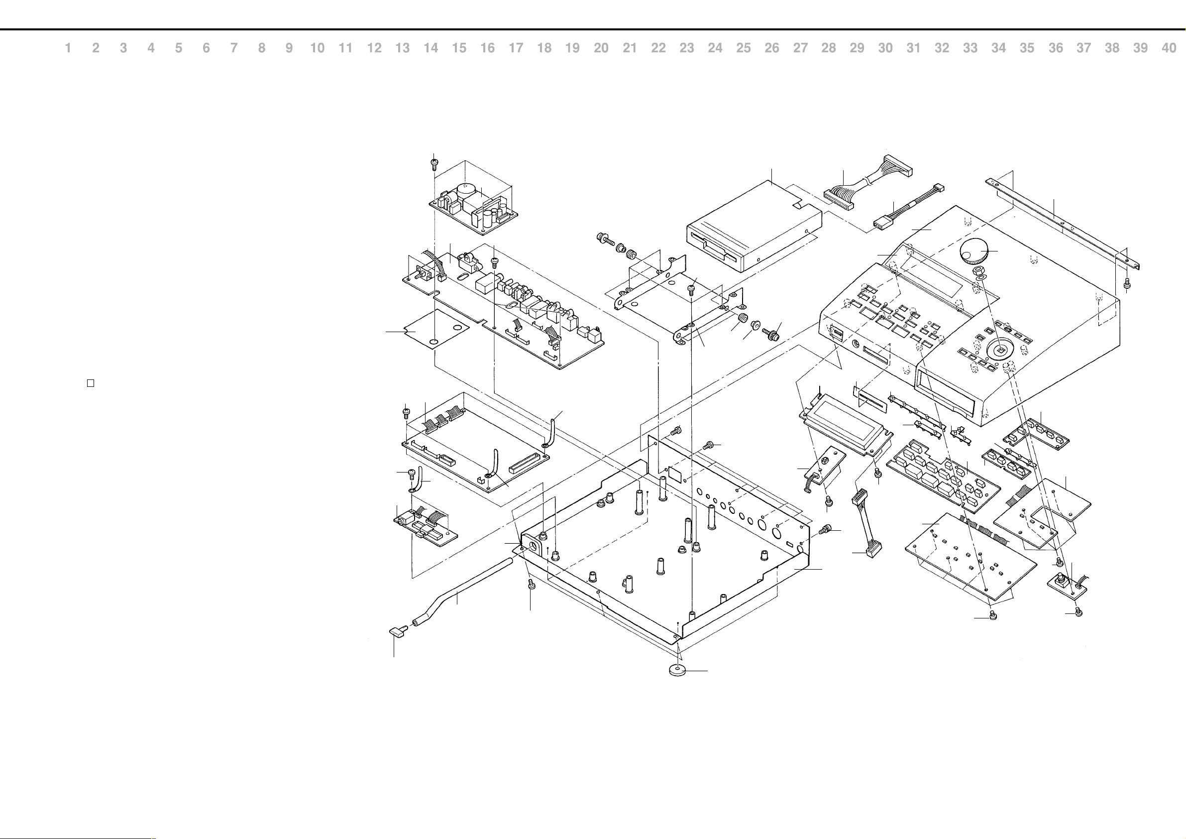
EXPLODED VIEW
B
[Part]
No. Part Code Part Name
q 01676245 DISPLAY COVER
C
w 01785890 TOP CASE for JAPANESE
01676212 TOP CASE for ENGLISH
e 22485303 DR-KNOB L BLK 248-303
D
r 01676234 CHASSIS HOLDER
t 71013990 LCD UNIT
y 01676256 POT DUST COVER
E
u 01561445 LED LENS LENS A
i 01561467 LED LENS LENS C
o 01561456 LED LENS LENS B
F
!0 01561434 RUBBER SW C
!1 01561423 RUBBER SW B
!2 01344923 RUBBER SW A
G
!3 71231756 PANEL R BOARD ASSY
!4 71231723 LED BOARD ASSY
!5 71231745 PANEL L BOARD ASSY
H
!6 71231734 ENCODER BOARD ASSY
!7 01451678 SWITCHING REGULATOR KW1AA265
I
!8 71231767 ANALOG BOARD ASSY
!9 01788045 FDD UNIT MF355F-3252MG(REV.F)
@0 01564234 DD HOLDER
J
K
L
M
N
O
P
Q
R
E
@1 71231989 MAIN BOARD ASSY
@2 71231778 PHONE BOARD ASSY
@3 01676223 BOTTOM COVER
@4 01235378 FOOT
@5 22140236 ARM
@6 22485298 I S-KNOB S DWG/LCG 248-298
@7 40017378 COATING CLIP CS-7
@8 22265242 DD INSULATER 226-242
@9 22165134 COLLAR 216-134
#0 01561478 LED LENS LENS D
#1 01896656 WIRING (W20) FDD 34P
#2 01785778 INSULATING SHEET
#3 01676312 ARM CUSHION
#4 01675689 WIRING W13 FDDPWR 26AWG
#5 01675678 WIRING W6 LCD-MAIN
[SCREW]
No. Part Code Part Name
A 40011056 SCREW M3×6 BINDING B-TIGHT ZC
B 40011101 SCREW M3×8 BINDING TAPTITE-B FE BZC
C 40011278 SCREW M3×8 BINDING P-TITE FE ZC
D 40011312 SCREW M3×8 BINDING P-TITE FE BZC
E 40011501 SCREW M3×8 SEMS. PAN HEAD FE BZC
F 40012878 SCREW M3×10 PAN SEMS FECM W/SW+PW
/分解図
#2
A
@6
@2
A
@1
A
@7
!8
@5
!7
A
#3
@7
D
@7
B
A
@6
@4
@8
D
@9
!9
F
!4
t
C
@3
#1
E
#5
y
q
C
#4
u
i
w
!5
o
!2
C
!1
r
e
C
!0
#0
!3
!6
C
C
S
T
U
V
IMPORTANT : After replacing wiring, #2 INSULATING SHEET or shifting them for replacing
purpose, restore original clamping and dressing.
重 要 : 修理等でワイヤリング、インシュレーティングシートを交換したり、位置を
変えた場合には必ず元の位置に戻してください。
3
Page 4
MT-300 Jan. 1999
A
B
C
D
E
F
G
H
I
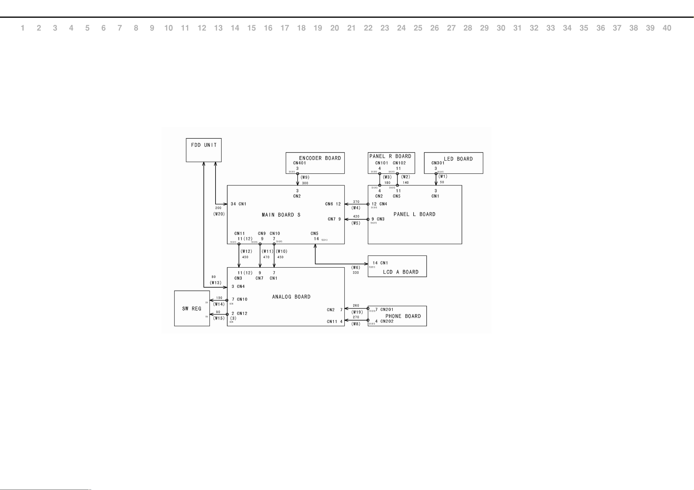
WIRING DIAGRAM
/ワイヤリング配線図
J
K
L
M
N
O
P
Q
R
<CODE NUMBER TABLE>
W1 01675745
W2 01675767
W3 01675778
W4 01675789
W5 01675790
W6 01675678
W8 01675734
W9 01675756
W10 01675690
W11 01675701
W12 01675712
W13 01675689
W14 01675801
W15 01675823
W19 01894845
W20 01896656
S
T
U
V
4
Page 5

MT-300 Jan. 1999
PARTS LIST
SAFETY PRECAUTION:
The parts marked
related characteristics.
Use only listed parts for
replacement.
安全上の注意:
が付いている部品は、安全
上特別な規格でつくられたも
のです。
交換の際は、指定された部品
番号以外の部品は使わないよ
うにして下さい。
have safety-
/パーツリスト
CONSIDERATIONS ON PARTS ORDERING
When ordering any parts listed in the parts list, please specify the following items in the order sheet.
Failure to completely fill the above items with correct number and description will result in delayed or even
undelivered replacement.
パーツ発注に関するお願い
オーダーシートには、必ず下記の4項目は正確に記入して下さい。(例外は除く)
もし記入洩れ、誤記等が有る場合、必要部品が発送できなかったり、大幅な遅れの原因になりま
す。御協力をお願いします。
QTY PART NUMBER DESCRIPTION MODEL NUMBER
10 22575241 Sharp key C-20/50
Ex.
15 2247017300 Knob (orange) DAC-15D
必要数 パーツナンバー 品名 使用機種
10 22575241 Sharp key C-20/50
例)
15 2247017300 Knob (orange) DAC-15D
MAIN BOARD ASSY = MB
ANALOG BOARD ASSY = ANALOG
ENCODER BOARD ASSY = ENCODER
LED BOARD ASSY = LED
PANEL L BOARD ASSY = PANEL L
PANEL R BOARD ASSY = PANEL R
PHONE BOARD ASSY = PHONE
Note : Consider about the natural environment carefully before through the old lithium battery away when you exchange to
the new one.
注意:リチウム電池の交換時に、不要になったリチウム電池は、環境問題を十分考慮した上で処理して下さい。
NOTE1: *1 The parts marked # are new (initial parts).
NOTE2: *2 The parts marked
have safety-related characteristics.
注意1:#の付いた部品は新規部品です。
注意2:
の付いた部品は安全上特別な規格でつくられた部品です。交換の際は指定された部品番号以外の部
品は使用しないでください。
*1*2
↓↓ Q'ty
CASING
# 01676212 TOP CASE ENGLISH 1
# 01785890 TOP CASE JAPANESE 1
/ケース
NOTE : There are two types of FRONT PANEL ASSY,English version and Japanese version.
When ordering thisparts,please order specify parts.
注意 : FRONTPANELASSYには海外用(英語表記)と国内用(日本語表記)があります。
補修用部品を要求される際は、適切な部品をオーダーして下さい。
# 01676223 BOTTOM COVER 1
# 01676245 DISPLAY COVER 1
01561445 LED LENS LENS A 1
01561456 LED LENS LENS B 1
01561467 LED LENS LENS C 1
01561478 LED LENS LENS D 1
# 01676256 POT DUST COVER 1
CHASSIS
# 01676234 CHASSIS HOLDER 1
01564234 DD HOLDER 1
KNOB, BUTTON
22485303 DR-KNOB L BLK 248-303 1
22495626 F S-BUTTON SX DWG 249-626 1
22485298 I S-KNOB S DWG/LCG 248-298 1
01344923 RUBBER SW A 1
01561423 RUBBER SW B 1
01561434 RUBBER SW C 1
SWITCH
01453245 SDDLB1-B2-D-2 TV-5 PUSH SWITCH SW2 on ANALOG 1
00899223 SSSF124-S06N1 SLIDE SWITCH SW1 on ANALOG 1
JACK, SOCKET
00894001 3.5MM YKB21-5142 JACK JK201 on PHONE 1
13449283 6.5MM HLJ7101-01-3010 JACK JK7 on ANALOG 1
13449284 6.5MM HLJ7001-01-3010 JACK JK5 on ANALOG 1
13449252 6.5MM YKB21-5006 JACK(STEREO W/SW) JK2 on ANALOG 1
23425740 INL-8 10A/125V 2P PO AC INLET JK8 on ANALOG 1
13429911 TCS7927-28-401 JACK (RS422) JK3 on ANALOG 1
00451445 YKC21-3040 JACK JK1 on ANALOG 1
13429676 YKF51-5048 MIDI CONNECTOR JK6 on ANALOG 1
/シャーシ
/つまみ、ボタン
/スイッチ
/ジャック、ソケット
DISPLAY UNIT
/表示ユニット
71013990 LCD UNIT 1
NOTE : Replacement LCD UNIT should be made on a unit base.
注意 : LCDUNITの交換は、ユニット単位で行って下さい。補修品は、ユニット単位。
DISK DRIVE UNIT
01788045 MF355F-3252MG(REV.F) FDD UNIT 1
/ディスクドライブ・ユニット
NOTE : Replacement FDD MF355F-3252MG(REV.F) should be made on a unit base.
注意 : FDDMF355F-3252MG(REV.F)の交換は、ユニット単位で行って下さい。補修品は、ユニット単位。
POWER SUPPLY UNIT
01451678 KW1AA265 SWITCHING REGULATOR 1
/電源ユニット
NOTE : Replacement SWTNG REG KW1AA265 should be made on a unit base.
注意 : SWTNGREGKW1AA265の交換は、ユニット単位で行って下さい。補修品は、ユニット単位。
PWB ASSY
# 71231989 MAIN BOARD ASSY
/基板完成品
NOTE : ‘MAIN BOARD ASSY’ includes the following parts.
注意 : 補修用MAINBOARDASSYは、下記の部品を含みます。
# 01675690 WIRING W10
# 01675701 WIRING W11
# 01675712 WIRING W12
71015634 LCD A BOARD ASSY
# 71231778 PHONE BOARD ASSY
NOTE : ‘PHONE BOARD ASSY’ includes the following parts.
注意 : 補修用PHONEBOARDASSYは、下記の部品を含みます。
# 01894845 WIRING W19 CN201 on PHONE
# 01675734 WIRING W8 CN202 on PHONE
# 71231767 ANALOG BOARD ASSY
NOTE : ‘ANALOG BOARD ASSY’ includes the following parts.
注意 : 補修用ANALOGBOARDASSYは、下記の部品を含みます。
# 01675801 WIRING W14
# 01675823 WIRING W15
# 71231756 PANEL R BOARD ASSY
# 71231745 PANEL L BOARD ASSY
NOTE : ‘PANEL L BOARD ASSY’ includes the following parts.
注意 : 補修用PANELLBOARDASSYは、下記の部品を含みます。
# 01675767 WIRING W2 CN5 on PANEL L
# 01675778 WIRING W3 CN2 on PANEL L
# 01675789 WIRING W4 CN4 on PANEL L
# 01675790 WIRING W5 CN3 on PANEL L
# 71231734 ENCODER BOARD ASSY
NOTE : ‘ENCODER BOARD ASSY’ includes the following parts.
注意 : 補修用ENCODERBOARDASSYは、下記の部品を含みます。
# 01675756 WIRING W9 CN401 on ENCODER
# 71231723 LED BOARD ASSY
NOTE : ‘LED BOARD ASSY’ includes the following parts.
注意 : 補修用LEDBOARDASSYは、下記の部品を含みます。
# 01675745 WIRING W1 CN301 on LED
12169323 TR SPACER TR-1
IC
01126778 24LC01BT-I/SN IC EEPROM IC32 on MB 1
15199286 AN78L05M-(E1) IC REGULATOR IC10 on ANALOG 1
15199188 AN78M09F IC (V.RGL) IC17 on ANALOG 1
15199189 AN79M09F IC (V.RGL) IC20 on ANALOG 1
15199780 HD63266F IC (FDC) IC2 on MB 1
01344278 HD6437034AD72F IC CPU IC3 on MB 1
15269201H0 HD74LS04FPEL IC (TTL) IC15 on ANALOG 1
01341167 LH28F400SUT-NF60 IC FLASH MEMORY IC38 on MB 1
5
Page 6

MT-300 Jan. 1999
01348245 LH5S46NH DEMO IC MASK ROM IC15 on MB 1
15199937 M51953BFP IC (RESET IC) IC11 on ANALOG 1
15289109 M5216FP-600D IC (OP AMP) IC4 on ANALOG 1
15189261 M5218AFP-600E IC (OP AMP) TAPE IC1 3 16 on ANALOG 3
15289712 M5M34051FP-42A IC IC12 on ANALOG 1
00343823 M60205-0601FP IC (GATE ARRAY) IC8 on MB 1
01238012 M65850P IC DIGITAL ECHO IC9 on ANALOG 1
15289125 PC410KT 178FAY PHOTO COUPLAR IC14 on ANALOG 1
00232567 PCM69AU-1/2K IC DAC IC5 on MB 1
00897078 RA01-005 (TC170C200AF-005) IC (CUSTOM) IC13 on MB 1
15289402 TA78L05F(TE12L) IC REGULATOR IC6 on MB 1
01126612 TC514260DJS-60(YEL) IC (DRAM) IC22 23 on MB 2
01344256 TC5316200CF-HA01(TZ) IC MASK ROM IC18 on MB 1
15259740T0 TC74HC139AF(EL) IC (HS-CMOS) IC1 on PANEL L 1
15259823T0 TC74HC574AF(EL) IC (CMOS) IC2 on PANEL L 1
15259884 TC7S08F(TE85L) IC IC33 on MB, IC21 on ANALOG 1 + 1
15259885 TC7S32F(TE85L) IC (C MOS) IC11 26 on MB 2
15259887 TC7SU04F(TE85L) IC (CMOS) IC13 on ANALOG 1
00127490 TC7W08F(TE12L) IC (C MOS) IC19 on MB 1
00232645 TC7W14F(TE12L) IC IC35 on MB 1
15249111 TC7WU04F(TE12L) IC (C MOS) IC10 on MB 1
01349590 TC7WU04FU(TE12L) IC CMOS IC7 on MB 1
15289105 UPC4570G2-E2 IC (OP AMP) IC4 12 on MB, IC7 8 on ANALOG 2 + 2
TRANSISTOR
15309101 2SA1037KR T146 QRS TRANSISTOR Q16 19 on ANALOG 2
15319101 2SC2412KR T146 TRANSISTOR Q17 18 on ANALOG 2
15319105 2SC3326-A(TE85L) TRANSISTOR Q2-4 6 on ANALOG 4
15329507 DTA114EKT146 DIGITAL TRANSISTOR Q9 on ANALOG 1
15129198 DTA124ES TP DIGITAL TRANSISTOR Q14 on ANALOG 1
15329516 DTC114EKT146 TRANSISTOR Q4-11 on PANEL L 8
15129197 DTC144WSTP DIGITAL TRANSISTOR Q15 on ANALOG 1
00898201 RN2421-TE85L TRANSISTOR Q1 on MB, Q1-3 on PANEL L 1 + 3
DIODE
/ダイオード
15339120T0 1SS302-TE85R ARRAY DIODE DA2 on ANALOG 1
01121323 DA204UT106 ARRAY DIODE DA2 4 on MB, DA1 3 4 on ANALOG 2 + 3
15339105 DAN202K T146 ARRAY DIODE (CHIP) D101-105 on PANEL R, D1-9 on PANEL L 5 + 9
# 01781923 RD30M-T1B B ZENER DIODE D3-8 on ANALOG 6
15039142 S5688G(TPB5) RECTIFIER DIODE D9 on ANALOG 1
00348490 SLR-325VCT31 LED (RED)
00560745 SLR325MCT31 LED (PTR GREEN) LED2 on PANEL L 1
01121689 SPR-325MVWT31 LED (RED/GREEN) LED3-7 on PANEL L, LED301 on LED 5 + 1
RESISTOR
00126112 EXBV8V101JV RESISTOR ARRAY (CTA) RA31 38-40 on MB 4
15409113 EXBV8V103JV RESISTOR ARRAY RA13-18 20-23 34 35 41 on MB 13
01013578 EXBV8V470JV RESISTOR ARRAY RA2 3 5 19 24-27 29 30 32 on MB 11
15399965 RCE9A103JAG7A (10KOHM ×8) RESISTOR ARRAY RA1 4 6 7 12 28 on MB 6
POTENTIOMETER
13279884 RK09K1110 10KB POTENTIOMETER VR1 2 on ANALOG 2
01011645 RS30H12AD 50KB×2 30MM POTENTIOMETER (SLIDE) VR201 on PHONE 1
CAPACITOR
01453278 DE1307E 472M-KH CERAMIC CAPACITOR C134 on ANALOG 1
INDUCTOR, COIL, FILTER
01455623 N2012Z102T01
01566956 N2012ZA202T01 FERRITE- BEAD L1-14 on ANALOG 14
01459178 PLH11B8002R2P01B1 COIL FL1 on ANALOG 1
/トランジスター
/抵抗
/ボリューム
/コンデンサー
/インダクター、コイル、フィルター
INDUCTOR CEA FERRITE BEADS
LED101-103 on PANEL R, LED1 8-10 on PANEL L
L1-19 on MB 19
3 + 4
ENCODER
01013223 EVQ VEM F01 24B
CONNECTOR
13369925 53253-0310 CONNECTOR (3P)
13369926 53253-0410 CONNECTOR CN11 on ANALOG 1
13369929 53253-0710 CONNECTOR (7P) CN1 2 on ANALOG 2
13369931 53253-0910 CONNECTOR CN7 on MB 1
13369933 53253-1110 CONNECTOR CN3 on ANALOG 1
13369934 53253-1210 CONNECTOR CN6 on MB 1
01451556 53313-1415 CONNECTOR (14P) CN5 on MB 1
13369516 B9B-PH-KS JST CONNECTOR CN7 on ANALOG 1
13369877 PS-34PE-D4T1-B1-K CONNECTOR CN1 on MB 1
WIRING, CABLE
# 01675678 WIRING W6 LCD-MAIN CN5 on MB - CN1 on LCD A 1
# 01675689 WIRING W13 FDDPWR 26AWG CN4 on ANALOG - FDD 1
# 01896656 WIRING W20 FDD 34P CN1 on MB - FDD 1
SCREWS
40011056 SCREW M3×6 BINDING B-TIGHT ZC 18
40011312 SCREW M3×8 BINDING P-TITE FE BZC 8
40011278 SCREW M3×8 BINDING P-TITE FE ZC 19
40012878 SCREW M3×10 PAN SEMS FECM W/SW+PW 4
40011501 SCREW M3×8 SEMS. PAN HEAD FE BZC 1
40011101 SCREW M3×8 BINDING TAPTITE-B FE BZC 3
PACKING
# 01676267 PACKING CASE 1
# 01676278 LOWER PAD 1
# 01676289 UPPER PAD 1
MISCELLANEOUS
22140236 ARM 1
# 01676312 ARM CUSHION 1
40126812 CAUTION LABEL BARRIER(100V/117V ONLY) 1
22165134 COLLAR 216-134 4
22265242 DD INSULATER 226-242 4
01235378 FOOT 4
# 01785778 INSULATING SHEET 1
40017378 COATING CLIP 1
ACCESSORIES (Standard)
13499219 AC CORD SET (100V) DC-382-J01 1
13499220 AC CORD SET (117V) SJT2P 18AWG 60PO UC713 1
13499221 AC CORD SET (230V) EC-511-E07 1
13499222 AC CORD SET (240VA) SC-472-J03 (SC-078-J02) 1
00905234 ECP01-5A EURO CONVERTER PLUG 1
01456390 FLOPPY DISK DEMO JAPANESE 1
01456401 FLOPPY DISK DEMO ENGLISH 1
17049560 CONVERTER PLUG ANGLE (L TYPE) 2
23485228 MIDI CABLE 348-228 1M (BLACK) 1
00787534 ORIGINAL CONNECT CORD RCA PIN-PIN R/W 1.0M 1
71233345 OWNER’S MANUAL ENGLISH 1
71231667 OWNER’S MANUAL JAPANSES 1
# 40340056 LEAFLET DEMO SONG LIST 1
/エンコーダー
/コネクター
/ワイヤリング,ケーブル
/ねじ類
/梱包材
/その他
/標準付属品
POTENTIOMETER (ROTARY ENCODER)
EN401 on ENCODER 1
CN2 on MB, CN4 on ANALOG, CN1 on PANEL L
1+1+1
CRYSTAL, RESONATOR
00894034 MA-406 16.000MHZ TE24 CRYSTAL X1 on MB 1
00894023 MA-406 20000MHZ TE24 CRYSTAL X3 on MB 1
00901912 MA-406 24.576MHZ TE24 CRYSTAL X2 on MB 1
/クリスタル、発振子
6
Page 7

MT-300 Jan. 1999
HOW TO UPDATE THE FLASH MEMORY
フラッシュメモリーのバージョン
アップの方法
MT-300 uses Flash Memory for the main program registration.
With the productions, you can make the software update by floppy
disks via internal FDD. Please refer to the following "Update
Procedure."
◊ Required Item
MT-300/S Ver. Up Disk (P/No.17048697)
⋅
◊ Update Procedure
1. Insert the MT-300/S Ver. Up Disk into the disk drive.
Turn the power ON while holding [Tempo] and
[Metronome] buttons.
2: All of the LEDs on the panel blink as follows.
Normal : Blinks slowly
Error : Repeat quick double brink
3: When it is in normal condition, LCD may show "Flash
ROM Update" for a moment and loading the program
will be started. During the update, LCD will display as
follows."
The ******* and "##" part shows the working condition.
Refer to the following.
***** : ... Reading (now loading the program)
: ... Writing (now writing the program)
## : ... counts from 01 to 08
4: When the update procedure is normal ended, "finished"
will be displayed to the LCD. Turn ON the power again
and confirm the System Version number and execute
Test Mode.
If "finished" has not been displayed to the LCD display,
turn OFF and ON the power again and retry the update
procedure from the first. If the result is the same, contact
Roland Service Center.
MT−300は初期に生産された製品に限り、プログラムROM
にフラッシュメモリーが使用されています。
これらの製品は、内臓のディスクドライブより最新のプログ
ラムをロードすることにより、バージョンアップを
行なうことが可能です。手順は下記のとおりです。
*プログラムROMにマスクROMが使用されている製品に
ついては、基板ごと最新のものと交換するか、マスクR
OMを最新のものに交換してください。
◇用意するもの
MT−300/SVer.UpDisk(部品番号17048697)
⋅
◇バージョンアップ作業
1.本体にバージョンアップディスクを入れ、[テンポ][メ
トロノーム]ボタンを押しながら
電源を入れます。
2.パネル上のすべてのLEDが次のように点滅します。
正常な場合…ゆっくりと点滅します
エラーがある場合…2回早い点滅を繰り返します
3.エラーがなければLCDに「FlashROMUpdater」と表示
され、その後、自動でバージョンアップが始まりま
す。その時LCDは以下のような表示になります。
*****と##には下記のような表示が現れ、作業
状態を知らせます。
***** :…Reading
:…Writing
## :…01〜08の数字
4.アップデートが問題なく終了すればLCDに「finished」
と表示されます。
再度電源を入れ直し、テストモードにてビルド番号と
動作を確認して下さい。
「finished」と表示されなかった場合は一旦電源を切
り、もう一度手順1からやり直して下さい。
それでも正常に終了しなかった場合はローランドサー
ビスセンターまでお問い合わせ下さい。
(プログラム読み込み中)
(プログラム書き込み中)
TEST MODE
* Required Items
MIDI Cable
⋅
Computer Test Cable for Sound Canvas SC-88 (P/No.
⋅
17049906)
3.5inch Floppy Disk (Formatted)
⋅
(2HD : 1.44MB×1, 2DD : 720KB×1)
Expression pedal EV-5
⋅
Foot Pedal DP-6
⋅
Microphone
⋅
Oscilloscope
⋅
Headphone
⋅
1. Entering test mode
After turning on the power, press the [Metronome] button while
holding down the [Song] and [Count In] button to enter the
Test Mode. The following display will appear, and you will
enter test mode.
V*** : version number
B*** : build number (This is for factory use only)
*** : destination region (DOM: 100V specs, EXP: 117/
230/240V specs)
C*** : CPU build number (This is for factory use only)
* (Build number) and (CPU build number) are generally
not displayed in the LCD, but some units of the initial
production may display these. As this numbers are
displayed for factory purpose, please ignore when you
execute Test mode during the repair.
Press the [Transpose] button to move to item 2
* To advance to the next item you will generally use the
[Transpose] button.
For some items, you will advance automatically, so refer to the
explanation of each item.
* If you wish to exit test mode during this procedure, turn
off the power.
2. Device check and display of ROM version, etc.
During the device check, the following display will appear.
テストモード
*用意するもの
MIDIケーブル
⋅
コンピューター・テストケーブル
⋅
(サウンド・キャンバスSC-88用PartNo.17049906)
フォーマット済みフロッピーディスク
⋅
(2HD:1.44MB,2DD:720KB各1枚)
エクスプレッションペダルEV-5
⋅
フット・ペダルDP-6
⋅
マイク
⋅
オシロスコープ
⋅
ヘッドフォン
⋅
1. テストモードに入る
本体電源ON後に[曲]、[カウントイン]ボタンを押しな
がら[メトロノーム]ボタンを押して下さい。
LCDが以下のように表示され、テスト・モードに入り
ます。
V*** : バージョン番号
B*** : ビルド番号(サービス修理においてはこの
番号は関係ありません。)
*** : 仕様地域(DOM:100V仕様、EX
P:海外仕様)
C*** : CPUビルド番号(サービス修理において
はこの番号は関係ありません。)
*ビルド番号、CPUビルド番号は表示されるものとさ
れないものがあります。
(これらの表示はサービス的には意味を持ちません
ので、表示、非表示に関わらず無視して下さい。)
[移調]ボタンを押すと項目2に移ります。
*項目を進めるには、基本的に[移調]ボタンで行って
下さい。
項目によっては自動で次に進むものもあるので、各項
目の説明を参照して下さい
2. デバイス・チェックとROMバージョン等の表示
デバイス・チェックの最中は、LCDが以下のような表
示になります。
7
Page 8

MT-300 Jan. 1999
If a problem is found, the following error display will appear.
DEVICE (Error content)
Err PROGRAM ROM
Program (Flush or mask ROM) fault
Err DRAM Work DRAM read/write fault
Err Wave ROM Wave ROM data content fault
Err RAM for DSP DSP RAM read/write fault
Err EEPROM EEPROM read/write fault
Err DATA ROM DATA ROM data content fault
Err DATA TYPE DATA ROM type check fault
Err FDC EX PORT FDC EXISENCE PORT fault
If the test results were OK, the following display will appear.
(If the test result were NG, press [Transpose] to advance to next
test item.)
Press the [Transpose ] button to advance to item 3.
3. Button and LED check
All LEDs will light, and the following display will appear.
Note : If you wish to check item 3, do not press the
[Transpose] button first.
If you press the [Transpose] button first, you will
advance to item 4.
NGの場合は下記のようにエラー表示されます。
DEVICE(エラー内容)
エラー内容 不良デバイス
ErrPROGRAMROM
ProgramROM
ErrDRAM WorkingDRAM
ErrWaveROM WaveROM
ErrRAMforDSP DSP用RAM
ErrEEPROM EEPROM
ErrDATAROM
DataROMチェックサムエラー
ErrDATATYPE DataROM種別照合エラー
ErrFDCExPort FDCexistenceportエラー
エラー表示が出た場合には、[移調]ボタンを押してテ
ストモードを進めて下さい。
OKの場合は以下のように表示されます。
[移調]ボタンを押すと項目3に進みます。
3.ボタン及びLED類の確認
LEDが全て点灯し、LCDが以下のように表示されま
す。
注意:項目3の確認を行う場合は、最初に[移調]ボタ
ンを押さないで下さい。
最初に[移調]ボタンを押すと、項目4に移って
しまいます。
If all buttons are normal, you will automatically advance to item 4.
4. Checking the effect sound and panning etc.
Connect headphone cable into PHONES jack. Move volume
Slider Suitably.
The following display will appear and LEDs of [Track], [Count
In], [Metronome] will blink red.
Press the following buttons to check the effect sound and the
panning etc.
BUTTON PANNING TONE EFFECT INDICATION of LCD
[R] CENTER PIANO none DRY
[1] CENTER PIANO CHORUS CHORUS
[2] CENTER PIANO REVERB REVERB
[3] CENTER PIANO
[4] LEFT
[Count In]
[Metronome]
RIGHT
CENTER 440Hz sine wave none PAN LR
440Hz sine wave
440Hz square wave
RESONANCE
none PAN L
none PAN R
RESONANCE
Press the [Transpose] button to advance to item 5.
5. Pedal operation check
Connect the Expression pedal and Foot pedal Expression to the
Expression Pedal Jack and Start/Stop Jack.
LEDs of [R] [1] buttons blink red and the following display will
appear.
ボタンが全て正常であれば自動的に項目4に移ります。
4. エフェクト音・パンニング等のチェック
ヘッドフォンケーブルをヘッドフォンジャックに差し
ボリュームを適当に上げる。
LCDの表示が以下のようになり、トラック、カウン
トイン、メトロノームの各LEDが赤点滅します。
以下の各ボタンを押してエフェクト音のチェック及
び、パンニング等のチェックを行って下さい。
ボタン パンニング 音色 効果音 LCDの表示
[R] 中央 ピアノ 無し DRY
[1] 中央 ピアノ コーラス CHORUS
[2] 中央 ピアノ リバーブ REVERB
[3] 中央 ピアノ
[4] 左
[カウントイン]
[メトロノーム]
右
中央
440Hz正弦波
440Hz矩形波
440Hz正弦波
レゾナンス
無し PANL
無し PANR
無し PANLR
[移調]ボタンを押すと、項目5に移ります。
5. ペダルの動作確認
Expressionペダルとフットペダルをそれぞれ
ExpressionPedalジャックとStart/Stopジャックに接続
します。
[R][1]ボタンのLEDが赤点滅をし、LCDが以下のよ
うな表示になります。
RESONANCE
Once you begin the checking process for this test item, it is not
possible to advance to the next item before testing all buttons.
Press the following buttons, and confirm that a sound is heard
and that the button LED goes dark.
[Marker A] [Marker B] [Repeat] [Transpose] [Count In]
[Metronome] [Play] [Rec]
Press the following button twice, and confirm that a sound is
heard and that the button LED changes from orange to
green to dark.
[R] [1] [2] [3] [4]
Press the following button twice, and confirm that a sound is
heard and that the button LED on the left side of the
display changes from orange to green to dark, and that the
button LED goes dark the second time.
[Song]
Press the following buttons, and confirm that a sound is heard
and that the characters shown in the LCD disappear.
[Marker Clear]…M, [Beat]…B, [Tempo]…T, [Menu]…M,
[Disk]…D, [Tune]…T
[Reverb]…R, [Edit]…E, [Reset]…R, [Stop]…S, [Bwd]…B,
[Fwd]…F, [16Track]…1
確認作業に入った場合、すべてのボタンのテストを終
了させない限り次の項目に進まないようになっていま
す。
以下のボタンを押し、音が出て各ボタンのLEDが消灯
するのを確認して下さい。
[マークA][マークB][繰返し][移調][カウントイン]
[メトロノーム][再生][録音]
以下のボタンを2度押し、音が出て各ボタンのLEDが
オレンジ色、緑色、消灯と変化するのを確認して下さ
い。
[R][1][2][3][4]
以下のボタンを2度押し、音が出てディスプレイ左端
のLEDがオレンジ色、緑色、消灯と変化するのを確認
して下さい。
[曲]
以下のボタンを押して、LCDに表示されている対応す
る文字が消えるのを確認して下さい。
[マーク取り消し]…M、[拍子]…B 、[ テンポ]… T、 [メ
ニュー]…M、[ディスク]…D、[チューニング]…T
[リバーブ]…R、[エディット]…E、[曲の頭]…R、[停
止]…S、[巻戻し]…B、[早送り]…F、[16トラック]…1
(文字はLCD左から順番に)
At this time, you can move to item 6 by pressing [Transpose].
Slowly depress the Expression pedal and confirm that the value
on the LCD changes 0 to 9, and that the metronome sound
is heard when the display reaches "9." If test ends normally, [R]
LED goes dark.
Depress the Foot pedal and confirm that the "ON" displayed on
the LCD and metronome sound is heard.
Next release the pedal and confirm that the "OFF" displayed on
the LCD. If test ends normally, [1] LED goes dark.
If no problem is found, you will automatically advance to the
following item.
6. Encoder operation check
The following display will appear.
Rotate the Encoder clockwise. Value in the LCD increase and
when it reaches to "30", "OK" is displayed at INC of the LCD.
Next rotate the Encoder counterclockwise. Value in the LCD
decrease and when it reaches to "0", "OK" is displayed at DEC
of the LCD.
Press the [Transpose] button to advance to item 7.
8
この時点で項目6に移るには、[移調]を押して下さい。
Expressionペダルをゆっくり踏み込んで、LCDのEXの
値が0〜9と徐々に変化し、「9」の時に音が鳴るの
を確認して 下さい。正常に動作すると[R]ボタンの
LEDが消灯します。
フットペダルを踏んで、LCDのSSに「ON」が表示さ
れて音が鳴り、離すと「OFF」が表示されるのを確認
して下さい。正常に動作すると[1]ボタンのLEDが消
灯します。
2つとも操作して異常が無ければ、自動で次の項目に
移ります。
6. エンコーダーの動作確認
LCDが以下のような表示になります。
エンコーダーを時計回りに回すと数値が増え、「30」
になるとLCDのINCに「OK」と表示されます。その
まま反時計回りに回すと数値が減り、「0」になると
LCDのDECに「OK」と表示されます。
[移調]ボタンを押すと項目7に移ります。
Page 9

MT-300 Jan. 1999
7. Serial interface check
The following display will appear.
MIDI operation check
⋅
Set the computer switch to the MIDI position. "▲" symbol will
be displayed to the middle of "MI" in the LCD.
Using a MIDI cable, connect the MIDI IN to the MIDI OUT
located at the back of MT300S.
If the test result is OK, the LCD will indicate "OK" as follows.
Computer interface operation check
⋅
Connect a computer test cable (part no. 17049906) to the
Computer connector located at the back of MT300S.
Set the computer switch to Mac, PC-1 or PC-2, an underline
will be displayed below the corresponding position
(zMc","P1" or "P2") in the LCD. Then turn on the switch of
the computer test cable. If the result is OK, "OK" will appear
at the each position of the LCD.
*In the case of computer switch is set to Mac.
In the case of the Mac settings, Check both ends of the white
conductor (signal) and black conductor (ground) of the test
cable by oscilloscope, and confirm that a 1 MHz square wave is
present.
Press the [Transpose] button to advance to item 8.
8. Floppy Disk Drive check
*NOTE : After this check, data within the disks will be lost.
The following display will appear.
Prepare the 2DD Disk and 2HD Disk.
Insert a 2DD disk (protect ON) and check the display [2DD :
Protected].
Insert a 2HD disk (protect OFF) and check the display [2HD :
OK].
If an error occurs, the problems will be indicated as follows.
Unformated-----Disk did not formatted correctory.
NG---------------There is a failure in the disk or disk drive.
Press the [Transpose] button to proceed to item 9.
7. シリアルインターフェースの確認
LCDが以下のような表示になります。
・MIDIの動作確認
コンピューター・スイッチをMIDI側にして下さい。
LCDの「MI」の左側に▲マークが表示されます。
本体背面のMIDIInとMIDIOutをMIDIケーブルで接続
して下さい。
OKならばLCDに以下の様に「OK」が表示されます。
・コンピューター・インターフェースの動作確認。
コンピューター・テストケーブル(Part
No.17049906)を本体背面のComputer端子に接続して
下さい。
コンピューター・スイッチをMac/PC-1/PC-2に切り替
えると、それぞれLCD上の「Mc」「P1」「P2」に下
線がつきます。ここで、コンピューター・テストケー
ブルのスイッチをONにすると正常ならばL CD 上の
「Mc」「P1」「P2」に以下のようにそれぞれ「OK」
が表示されます。
Macの場合はコンピューター・テストケーブルの端子
波形をオシロスコープで見て、1MHzのクロックが出
ていることを確認して下さい。
[移調]ボタンを押すと項目8に移ります。
8. ディスクチェック
*注意:このチェックを行うと、ディスクの内容が破
壊されます。
LCDが以下のような表示になります。
あらかじめ用意しておいた2枚のディスクを使用します。
ライトプロテクトをONにした2DDディスクを挿入し
て、LCDに「2DD:Protected」と表示されることを確
認します。
次にライトプロテクトをOFFにした2HDディスクを挿
入して、LCD「2HD:OK」と表示されることを確認
します。
ディスクを挿入したとき、以下のように表示される場
合があります。
Unformated・・・ディスクが正しくフォーマットされて
いない場合
NG・・・・・・・・・ディスクやFDDに何か不具合がある場合
[移動]ボタンを押すと項目9に移ります。
9. LCD check
When you enter this mode, the entire LCD will go dark.
Next, press the [Transpose] button and confirm that the LCD
lights entirely as following.
Press the [Transpose] button again. Confirm the following
display will appear in the LCD.
Press the [Transpose] button to proceed to item 10.
10. Destination region setting
The following display will appear.
"DOM" or "Exp" is indicated at
Now press the [Beat] button to select DOM (100V)
specifications, or press the [Tempo] button to select EXP (117/
230/240V) specifications.
* When you enter this setting, the MT300 will automatically
return to the factory settings.
Press [Transpose] button to proceed to the next test.
***
11. Exiting test mode
Then all test ends, the following display will appear.
To exit test mode, turn off the power.
(If press the [Transpose] button here, you can jump to the first
item of the Test Mode.)
12. Mic check
After exiting test mode, connect a mic to the Mic In jack and
rotate the knobs (Mic Volume and Mic Echo) to verify that
each function operates correctly.
9.LCDチェック
このモードに入るとLCDが全消灯します。
次に[移調]ボタンを押すとLCDが以下のように全点灯
することを確認してください。
更に[移調]ボタンを押すとLCDが以下のように表示さ
れます
表示が下図と同様であることを確認してください。
ここで[移調]ボタンを押すと項目10へ移ります。
10. 仕様地域の設定
LCDが以下のような表示になります。
***にはDOM(国内)またはEXP(海外)が表示されま
す。ここで[拍子]ボタンを押すとDOM仕様に、[テン
ポ]ボタンを押すとEXP仕様になります。
*この設定に入るとMT-300は自動的に工場出荷時の
設定に戻ります。
[移調]ボタンを押すと次のテストに移ります。
11. テストモードの終了
すべてのテストが終了すると、LCDに以下のように表
示されます。
ここでもう一度[移調]ボタンを押すと、テストモード
の最初に戻ります。
テストモードを抜けるには、一度電源を切って下さ
い。
12. マイクチェック
リアパネルのMicジャックにマイクを差し込み、Mic
Volume/MicEchoを回してそれぞれの機能が正常に動
作することを確認して下さい。
9
Page 10

MT-300 Jan. 1999
A
BLOCK DIAGRAM/ブロック図
B
C
D
E
F
G
H
I
J
K
L
M
N
O
P
Q
R
S
T
U
V
10
Page 11

MT-300 Jan. 1999
A
CIRCUIT BOARD (MAIN)
/基板図(MAIN)
B
C
D
E
F
G
H
I
J
K
L
M
N
O
P
Q
View from components side.
View from foil side.
R
S
T
U
V
11
Page 12

MT-300 Jan. 1999
A
CIRCUIT DIAGRAM (MAIN) /回路図(MAIN)
B
C
D
E
F
G
H
I
J
K
L
M
N
O
P
Q
R
S
T
U
V
12
Page 13

MT-300 Jan. 1999
A
CIRCUIT BOARD (ANALOG)
/基板図(ANALOG)
B
C
D
E
F
G
H
I
J
K
L
M
N
O
P
Q
View from components side.
R
S
T
U
V
View from foil side.
13
Page 14

MT-300 Jan. 1999
A
CIRCUIT DIAGRAM (ANALOG)
/回路図(ANALOG)
B
C
D
E
F
G
H
I
J
K
L
M
N
O
P
Q
R
S
T
U
V
14
Page 15

MT-300 Jan. 1999
A
CIRCUIT BOARD (PANEL)
/基板図(PANEL)
B
C
D
E
F
G
H
I
J
K
L
M
N
O
P
Q
R
S
T
U
V
View from components side. View from foil side.
15
Page 16

MT-300 Jan. 1999
A
CIRCUIT DIAGRAM (PANEL) /回路図(PANEL)
B
C
D
E
F
G
H
I
J
K
L
M
N
O
P
Q
R
S
T
U
V
16
 Loading...