

Page 1

MDX-20
MDX-15
USER'S MANUAL
This User's Manual is intended for MDX-20 and MDX-15.
Thank you very much for purchasing the MDX-20/15.
To ensure correct and safe usage with a full under-
standing of this product's performance, please be sure
to read through this manual completely and store it in
a safe location.
Unauthorized copying or transferral, in whole or in
part, of this manual is prohibited.
The contents of this operation manual and the speci-
cations of this product are subject to change without
notice.
The operation manual and the product have been
prepared and tested as much as possible. If you nd
any misprint or error, please inform us.
Roland DG Corp. assumes no responsibility for any
direct or indirect loss or damage which may occur
through use of this product, regardless of any failure
to perform on the part of this product.
Roland DG Corp. assumes no responsibility for any
direct or indirect loss or damage which may occur with
respect to any article made using this product.
Page 2

For the USA
FEDERAL COMMUNICATIONS COMMIS-
SION RADIO FREQUENCY INTERFERENCE
STATEMENT
NOTE:
This equipment has been tested and found to comply with the
limits for a Class A digital device, pursuant to part 15 of the
FCC Rules. These limits are designed to provide reasonable
protection against harmful interference when the equipment
is operated in a commercial environment. This equipment
generates, uses, and can radiate radio frequency energy and, if
not installed and used in accordance with the instruction manual, may cause harmful interference to radio communications.
Operation of this equipment in a residential area is likely
to cause harmful interference in which case the user will be
required to correct the interference at his own expense.
Unauthorized changes or modication to this system can void
the users authority to operate this equipment.
Use only I/O cables that have been designed and manufac-
tured specically for this device.
For Canada
NOTICE
This Class A digital apparatus meets all requirements of the
Canadian Interference-Causing Equipment Regulations.
AVIS
Cet appareil numérique de la classe A respecte toutes les
exigences du Règlement sur le matériel brouilleur du Canada.
For California
WARNING
This product contains chemicals known to cause cancer,
birth defects and other reproductive harm.
For EU Countries
Manufacturer:
ROLAND DG CORPORATION
1-6-4 Shinmiyakoda, Kita-ku, Hamamatsu-shi, Shizuoka-ken, 431-2103 JAPAN
The authorized representative in the EU:
Roland DG Corporation, German Ofce Halskestrasse 7, 47877 Willich, Germany
For EU Countries
WARNING
This is a Class A product. In a domestic environment this product may cause radio interference in which
case the user may be required to take adequate measures.
RolandDG Corp. has licensed the MMP technology from the TPL Group.
Page 3

Table of Contents
To Ensure Safe Use ............................................................................................................... 3
About the Labels Axed to the AC Adapter and Unit .................................................................................................... 5
1 What You Can Do with MODELA .............................................................................................6
2 Check the Included Items .........................................................................................................7
3 Part Names ..............................................................................................................................8
4 Setting Up and Connection ......................................................................................................9
Connecting the AC Adapter and Power Cord ..................................................................................................................... 9
Connecting with Computer .....................................................................................................................................................10
5 Installing the Software ............................................................................................................ 11
Software That Can Be Used with the MODELA .................................................................................................................11
System requirements .................................................................................................................................................................11
Setting Up the Program ............................................................................................................................................................12
Changing the Port .......................................................................................................................................................................13
Application Settings ...................................................................................................................................................................15
How to Use Help ..........................................................................................................................................................................18
6 Operation Guide [Cutting Section] .........................................................................................19
Create the Cutting Data ............................................................................................................................................................19
Attach the Spindle Unit .............................................................................................................................................................22
The Mounting Locations for the Spindle Unit ...................................................................................................................23
Install the Cutting Tool .............................................................................................................................................................. 24
Maximum cutting area of the MODELA ..............................................................................................................................26
Load the Workpiece ....................................................................................................................................................................26
Attach the Front Cover ..............................................................................................................................................................27
Powering ON .................................................................................................................................................................................28
Perform Surfacing ....................................................................................................................................................................... 28
Perform Cutting ...........................................................................................................................................................................33
Pausing or stopping operation ...............................................................................................................................................33
When Cutting is Finished ..........................................................................................................................................................34
7 Operation Guide [Scanning Section] ...................................................................................... 36
Step 1: Attach the Sensor Unit ................................................................................................................................................36
Step 2: Load the Object to Be Scanned on the MODELA ..............................................................................................38
Step 3: Attach the Front Cover ................................................................................................................................................40
Step 4: Powering ON ..................................................................................................................................................................40
Step 5: Setting Scanning Conditions and Starting Scanning ......................................................................................41
Step 6: Setting the scanning area ..........................................................................................................................................42
Step 7: Saving Scanned Data ...................................................................................................................................................44
Step 8: Edit the Scanned Data .................................................................................................................................................44
When Scanning Is Finished ......................................................................................................................................................44
When not in use ...........................................................................................................................................................................44
8 Overview of the Usage Guides ..............................................................................................45
Overview of the Usage Guides ............................................................................................................................................... 45
Location of the Usage Guides .................................................................................................................................................45
Installing the Acrobat Reader .................................................................................................................................................45
9 Software Guide ......................................................................................................................46
Driver for Windows 95/98/Me .................................................................................................................................................46
Driver for Windows NT4.0/2000/XP ......................................................................................................................................48
MODELA 3D DESIGN ..................................................................................................................................................................50
MODELA 3D TEXT ........................................................................................................................................................................ 53
MODELA Player ............................................................................................................................................................................54
Virtual MODELA ...........................................................................................................................................................................54
Dr.PICZA ..........................................................................................................................................................................................56
Dr. Engrave .....................................................................................................................................................................................57
3D Engrave .....................................................................................................................................................................................60
10 What to Do If... .....................................................................................................................65
11 Items That May Not Be Copied ............................................................................................67
Table of Contents
1
Page 4

12 Specications ....................................................................................................................... 68
Main Unit Specications ...........................................................................................................................................................68
Modeling Functions ....................................................................................................................................................................68
Scanning Functions ....................................................................................................................................................................68
Interface Specication ................................................................................................................................................................ III
Please read this Agreement before unpacking the media. ...........................................................................................IV
Windows® and Windows NT® are registered trademarks or trademarks of Microsoft® Corporation in the United States
and/or other countries.
Adobe and Acrobat are trademarks of Adobe Systems Incorporated.
i486 and Pentium are registered trademarks of Intel Corporation in the United States.
AutoCAD® is registered trademark of Autodesk, Inc.
IBM is trademark of International Business Machines Corporation.
Other company names and product name are trademarks or registered trademarks of their respective holders..
http://www.rolanddg.com/Copyright © 2000-2012 Roland DG Corporation
2
Table of Contents
Page 5

To Ensure Safe Use
About WARNING and CAUTION Notices
WARNING
CAUTION
Used for instructions intended to alert the user to the risk of death or severe injury should
the unit be used improperly.
Used for instructions intended to alert the user to the risk of injury or material damage
should the unit be used improperly.
* Material damage refers to damage or other adverse eects caused with respect to the
home and all its furnishings, as well to domestic animals or pets.
About the Symbols
The symbol alerts the user to important instructions or warnings. The specic meaning of the symbol is
determined by the design contained within the triangle. The symbol at left means "danger of electrocution."
The symbol alerts the user to items that must never be carried out (are forbidden). The specic thing that
must not be done is indicated by the design contained within the circle. The symbol at left means the unit
must never be disassembled.
The symbol alerts the user to things that must be carried out. The specic thing that must be done is
indicated by the design contained within the circle. The symbol at left means the power-cord plug must be
unplugged from the outlet.
WARNING
CAUTION
Do not disassemble, repair, or modify.
Doing so may lead to re or abnormal operation resulting in injury.
Do not use with any power supply other
than the dedicated AC adapter.
Use with any other power supply may lead to
re or electrocution.
Use only with the power cord included with
this product.
Use with other than the included power cord
may lead to re or electrocution.
Ground the unit with the ground wire.
Failure to do so may result in risk of electrocu-
tion in the event of a mechanical problem.
Do not use with any electrical power supply
that does not meet the ratings displayed on
the AC adapter.
Use with any other power supply may lead to
re or electrocution.
Do not use while in an abnormal state (i.e.,
emitting smoke, burning odor, unusual
noise, or the like).
Doing so may result in re or electrical shock.
Immediately unplug the power-cord plug
from the electrical outlet, and contact your
authorized Roland DG Corp. dealer or service
center.
Do not use with a damaged AC adapter, power cord, or power-cord
plug or with a loose
electrical outlet.
Use with any other power supply may lead to
re or electrocution.
When not in use for
several hours, unplug
the power-cord plug
from the electrical outlet.
Failure to do so may result in danger of shock,
electrocution, or re due to deterioration of the
electrical insulation.
Do not attempt to unplug the power-cord
plug with wet hands.
Doing so may result in
electrical shock.
Install on a stable surface.
Failure to do so may result in falling of the unit,
leading to injury.
To Ensure Safe Use
3
Page 6

CAUTION
CAUTION
Wear dust goggles
and mask during use.
Cutting dust may scatter, causing bodily injury.
Do not injure or modify the electrical power
cord, nor subject it
to excessive bends,
twists, pulls, binding,
or pinching, nor place
any object of weight on it.
Doing so may damage the electrical power
cord, leading to electrocution or re.
When unplugging the
electrical power cord
from the power outlet,
grasp the plug, not
the cord.
Unplugging by pulling
the cord may damage
it, leading to re or electrocution.
During cutting or
scanning, do not place
hands near the cutting
tool or the probe.
Doing so may result in
injury.
While the power is
on, do not remove the
spindle unit from the
carriage.
Doing so may result in
injury.
Store clay out of the
reach of children.
When you’re nished,
wash your hands to
rinse away all cuttings.
Do not allow liquids,
metal objects or ammables inside the machine.
Such materials can
cause re.
Do not touch the tip of
the cutting tool with
your ngers.
Doing so may result in
injury.
Do not allow children
to operate without
adult supervision or
operate within reach
of young children.
Doing so may result in
injury.
In case of emergency,
immediately unplug
the AC adapter.
Do not operate if a
transparent cover is
cracked or broken.
If the transparent cover
at the front or the side
of the unit is cracked,
contact a service agent immediately for repairs.
Use a commercially
available brush to remove metal cuttings.
Attempting to use a
vacuum cleaner to take
up metal cuttings may
cause re in the vacuum cleaner.
4
To Ensure Safe Use
Page 7

About the Labels Afxed to the AC Adapter and Unit
These labels are axed to the body of this product and the AC adapter. The following gure describes the location.
Rated power supply
Do not use with any electrical power supply
During cutting or scanning,
keep hands away from the
cutting tool and the probe.
that does not meet the ratings displayed on
the AC adapter.
Model name
In addition to the WARNING and CAUTION symbols, the symbols shown below are also used.
NOTICE
Indicates information to prevent machine breakdown or malfunction and ensure
correct use.
Indicates a handy tip or advice regarding use.
To Ensure Safe Use
5
Page 8

1 What You Can Do with MODELA
Cut material to make a shape
MODELA cuts materials for three-dimensional objects made with software.
You can also engrave plates using at line-drawing data.
Create three-dimensional data from a shape
MODELA can scan the shape of a solid object and create three-dimensional data.
You can use this data to do things like changing the size or make use of a natural shape as part of another design.
Cutting a
shape
Engraving
Use software to
create a three-dimensional object.
3D Design etc. MODELA Player
Use software design
a line drawing.
Dr.Engrave etc.
Enter the parameters
for cutting the threedimensional object
(cutting parameters).
Enter the parameters
for engraving (engraving parameters).
Perform cutting. Finished result.
Perform engraving. Finished result.
2.5D Driver
6
Prepare the threedimensional object.
Creating
data from
a shape
1 What You Can Do with MODELA
Enter the parameters
for scanning.
Dr.PICZA
Perform scanning. Finished result.
Dr.PICZA
Page 9

2 Check the Included Items
AC adapter: 1 Power cord: 1 Roland software package: 1
Spindle unit: 1 (*1)
Tool: 1 (High speed steel) The shape of
the tool may dier from that below.
Hexagonal wrench (size : 3 mm) :1
Hexagonal wrench (size : 1.5 mm): 1
Sensor unit: 1 (*1)
Set screw M3 x 3: 2 (One spare) Front cover: 1
Positioning pins: 3 (*2) (diameter 3
mm (0.118 in.), length 20 mm (0.787
in.)) (One spare)
Cap screw M4 x 15: 4 (Two spares)
Double sided tape: 1
The conguration
of the MDX-15
diers, but the attachment method
is the same.
Clay: 1
(*1) Do not discard the included-item box containing the spindle unit and sensor unit. It is needed to hold the unused unit while Modela
is in operation.
(*2) The positioning pin is used when performing double-sided cutting with MODELA. For detailed information about double-sided cutting,
see “Cutting Tips” in the included CD-ROM (refer to "8 Overview of the Usage Guides").
MDX-20/15 User's Manual: 1
2 Check the Included Items
7
Page 10

3 Part Names
NOTICE
• Do not touch the wire with the hands.
• Except when repacking the unit, do not attempt to move the table or carriage by hand.
In this manual, sections that explain commons points for the MDX-20/15, use only illustrations of the MDX-20. Some details
of the MDX-15 dier from the gure.
Front
Switch Panel
Carriage
Jack
MODELING
MODE LED
SCANNING
MODE LED
STANDBY key
Rear
VIEW LED
VIEW key
TOOL-UP key
Work plate
TOOL-DOWN key
Table
Wire
AC adapter jack
Serial connector
8
3 Part Names
Page 11

4 Setting Up and Connection
WARNING
WARNING
WARNING
WARNING
CAUTION
NOTICE
Never install this unit in any of the following situations, as it could result in damage:
• Places where the installation surface is unstable or not level.
• Places with excessive electrical noise..
• Places with excessive humidity or dust.
• Places with poor ventilation, because the MODELA generates considerable heat during operation.
• Places with excessive vibration.
Do not use with any power supply other than the dedicated AC adapter.
Use with any other power supply may lead to re or electrocution.
Do not use with any electrical power supply that does not meet the ratings dis-
played on the AC adapter.
Use with any other power supply may lead to re or electrocution.
Use only with the power cord included with this product.
Use with other than the included power cord may lead to re or electrocution.
Ground the unit with the ground wire.
Failure to do so may result in risk of electrocution in the event of a mechanical
problem.
Install on a stable surface.
Failure to do so may result in falling of the unit, leading to
injury.
Use within a temperature range of 5 to 40°C (41 to 104°F) and within a humidity range of 35 to 80%.
Securely connect the power cord, computer I/O cable and so on so that they will not be unplugged and cause
failure during operation. Doing so may lead to faulty operation or breakdown.
Connecting the AC Adapter and Power Cord
Connect in the order of the numbers shown in the gure.
30 cm (12 in.)
10 cm (4 in.)
Power cord
AC adapter jack
AC adapter
30 cm (12 in.)
* Do not place any object within the area
10 cm (4 in.)
4 Setting Up and Connection
9
Page 12

Connecting with Computer
Serial connector
IBM PC or PC compatible
Serial cable
(XY-RS-34 or equivalent)
If your computer is an IBM PC compatible personal computer, then use an optionally available XY-RS-14/34 cable (or
equivalent). A straight cable such as modem cable will not work.
Make sure the power to the computer and the MODELA is switched o before attempting to connect the cables.
10
4 Setting Up and Connection
Page 13

5 Installing the Software
Software That Can Be Used with the MODELA
The Roland Software Package CD-ROM contains many dierent kinds of software.
You can view the software that can be used with MODELA by displaying the setup menu on the CD-ROM and choosing the
model of MODELA.
See below for overviews and brief description of usage for the software displayed on the setup menu.
Software Overview
Windows
driver
MODELA
programs
MODELA
Player
MODELA
3D DE-
SIGN
MODELA
3D TEXT
Virtual
MODELA
Dr.Engrave
This is necessary when sending data to MODELA from a Windows-based program. If you’re using
Windows, be sure to install this driver.
The Windows versions of MODELA Player, MODELA 3D DESIGN, and MODELA 3D TEXT cannot be set
up separately.
This sets the required parameters for cutting solid objects and sends the cutting data to MODELA.
This can import not only solid objects created with three-dimensional programs from Roland DG
Corp., but also solid objects created using other commercially available three-dimensional programs
(via DXF or STL).
This lets you choose a basic shape such as a cylinder or sphere, and modify it to create a threedimensional object.
You can intuitively create solid objects with smooth curves.
You can use MODELA to cut solid objects and save data in three-dimensional DXF les.
This adds thickness to text to create three-dimensional characters.
It’s also possible to edit text to make it bold, italic, or the like. You can put a box around text with just
a single click — a handy feature when making nameplates.
You can use MODELA to cut three-dimensional text and save data in three-dimensional DXF les.
This simulates tool movement before performing cutting with MODELA.
You can use it to check the nished shape as well as things like whether the cutting depth is suitable
and how much time cutting will take. This can reduce loss for cutting materials and time.
This is used to design plates and send the engraving data to MODELA.
You can make large numbers of plates with the same design with high eciency. You can use the
TrueType fonts registered in Windows as the font style for text. You can even make stroke fonts from
TrueType fonts.
Because you can the outline of an image and convert it to line segments, it’s also possible to include
logos for companies or organizations in the plates you make.
3D En-
grave
Dr.PICZA
This adds thickness to a at (two-dimensional) graphic to create a relief (raised engraving). You can
also add thickness to images such as illustrations.
This scans the shape of a solid object with MODELA and creates three-dimensional data. You can use
it to rescan a particular portion, delete unneeded portions, cut a scanned three-dimensional object
with MODELA, or save data in any of four le formats, including DXF and STL.
System requirements
MODELA Ap-
plications
Operating system
Computer
Memory (RAM)
Free hard-disk
space required for
installation
Windows 95/98/Me/NT4.0/2000/XP
Computer running Windows (Pentium processor or better recommended)
32 MB or more recommended
7 MB 10 MB 10 MB 5 MB 3 MB
Dr.Engrave 3D Engrave Virtual MOD-
ELA
5 Installing the Software
Dr.PICZA
11
Page 14

Setting Up the Program
If you are installing under Windows NT 4.0/2000/XP, log on to Windows as "Administrators" account.
Switch on the computer and start Windows.
Place the CD from the Roland Software Package in the CD-ROM drive.
The Setup menu appears automatically.
Click the drop-down arrow next to [Click here], choose the
model you're using, then click [Install].
If you're using the MDX-20, choose [MDX-20]. If you're using the
MDX-15, choose [MDX-15].
To view the description of a program, click the button. To view
the manual, click the button.
(There are manuals in PDF format for the programs that the button
references. Acrobat Reader is required to view PDF les.)
If there are programs you don't want to install, then clear their check
boxes before you click [Install].
The Setup program starts. Follow the messages to carry
out setup and nish setting up the program.
* When the setup for one program nishes, the setup for the next
program starts.
In the interval until the next setup starts, a dialog box showing the
progress of processing is displayed.
12
5 Installing the Software
The driver settings appear.
Check the values, click [Close], and nish installing the
driver.
When all installation nishes, the screen shown below appears.
Click [Close].
Page 15

Remove the CD-ROM from the CD-ROM drive.
After returning to the menu screen for installation, click
.
Changing the Port
When the driver is installed, the port for output from the computer is automatically set to [COM1]. If MODELA is connected
to a port other than [COM1], follow the steps below to change the port setting.
* The explanations in this section describe operation of the MDX-20. If you're using the MDX-15, then where "MDX-20" ap-
pears in the text, read "MDX- 15" instead.
Driver for Windows 95/98/Me
Click [Start]-[Settings]-[Printer] to open the [Printer] folder.
Right-click on the Roland MODELA MDX- 20 icon, then
click [Properties].
The [Roland MODELA MDX-20 Properties] dialog box appears.
Click the [Details] tab. At [Print to the following port(s)],
choose an unused port other than [COM1].
Set [Transmission retry] to 3,600 seconds. Click the [Port
Settings] .
The [Port Settings] tab appears.
Make the settings for the following communication parameters. Click [OK].
5 Installing the Software
13
Page 16

Driver for Windows NT4.0/2000/XP
Open the [Printers] folder.
Windows NT4.0/2000:
Click [Start]-[Settings]-[Printers].
Windows XP:
Click [Start]-[Control Panel]. Click [Printers and Other Hardware], then click [Printers and
Faxes].
Right-click on the Roland MODELA MDX-20 icon, then
click [Properties].
The [Roland MODELA MDX-20 Properties] dialog box appears.
Click the [Ports] tab. For [Port], choose an unused port
other than [COM1]. Click [Conguration Port].
> Windows NT 4.0: go to step 4
> Windows 2000/XP: go to step 5
Click the port you chose in step 3, then click [Settings].
14
5 Installing the Software
Make the settings for the following communication parameters. Click [OK].
Page 17

Application Settings
When you nish installing the applications, continue by making the following settings. Be sure to make the settings before
use.
* The explanations in this section describe operation of the MDX-20. If you're using the MDX-15, then where "MDX-20" appears in the text, read "MDX- 15" instead.
MODELA Player
Click [Start] and point to [Programs].
Point to [Roland MODELA] and click [MODELA Player].
From the [Options] menu, click [Machines...].
The [Model Selection] dialog box appears.
Click [MDX-20], then click [OK].
From the [File] menu, click [Print Setup...].
The [Print Setup] dialog box appears.
Dr.PICZA
Click the drop-down arrow for the name and click [Roland MODELA
MDX-20].
Then click [OK].
Click [Start]. Point to [Roland Dr.PICZA] and click [Dr.
PICZA].
5 Installing the Software
15
Page 18

From the [File] menu, click [Preferences...].
The [Preferences] dialog box appears.
If You’re Using Windows NT4.0/2000/XP
If the printer port for the Windows driver and the communication port for Dr. PICZA are set to the same port, you
cannot use Dr. PICZA.
To perform scanning, you need to temporarily set the Windows driver printer port to a dierent port. After you
nish scanning, return the setting for the Windows driver to its original value.
Dr.Engrave
Select the port where the cable is connected, then click
[OK].
Click [Start]. Point to [Roland Dr.Engrave] and click [Dr.
Engrave].
16
5 Installing the Software
From the [File] menu, click [Print Setup...].
The [Print Setup] dialog box appears.
Page 19

3D Engrave
Click the drop-down arrow for the name and click [Roland
MODELA MDX-20]. Then click [OK].
Click [Start].
Point to [Roland 3D Engrave] and click [3D Engrave].
From the [Cut] menu, click [Machines...].
The [Model Selection] dialog box appears.
Click [MDX-20], then click [OK].
From the [File] menu, click [Output Device Setup].
The [Print Setup] dialog box appears.
Click the drop-down arrow for the name and click [Roland
MODELA MDX-20].
Then click [OK].
5 Installing the Software
17
Page 20

How to Use Help
If you have trouble using the program or driver, see the help screens. Help contains information such as descriptions of
software operation, explanations of commands, and tips for using the software more eectively.
From the [Help] menu, click [Contents].
Clicking on text that is green and underlined (by a solid or
dotted line) displays an explanation.
Clicking on an image area that contains an explanation
displays the explanation.
Tip:
- When the pointer moves over green underlined text, it changes to a
pointing hand (
- When the pointer moves over a location where an explanation is included, it changes to a pointing hand (
).
).
18
When there's a [?] button on screen
Clicking [?] in the upper-right corner of the window makes the mouse
pointer change to a question mark (
over any item you wish to learn more about, then click on the item to display
an explanation of it.
When there's a [Help] button on screen
Clicking [Help] lets you view help for the window or software..
5 Installing the Software
). You can then move the pointer
Page 21

6 Operation Guide [Cutting Section]
This section provides a step-by-step explanation of the basic procedures for cutting a solid objects with MODELA.
In this section, it is assumed that you have already completed making the three-dimensional data for the solid object. It is
assumed that the three-dimensional data you have prepared is three-dimensional data in DXF format.
- Open the three-dimensional data with MODELA Player and set the cutting parameters.
- Install the cutting tool and mount the workpiece on MODELA.
- Set the reference point for cutting.
- Perform surfacing and start cutting.
This explanation takes the sample data for the MODELA programs as an example of a solid object to be cut.
Create the Cutting Data
Prepare the data to be cut with MODELA, and set the cutting parameters with MODELA Player.
1.
Open the File
2.
Set the Cutting Parameters
The cutting parameters are the parameters for cutting the solid object.
For MODELA Player, make these settings:
Cutting surface : The surface of the solid object to be cut
Size : The size of the nished object
Depth : The depth of cutting
Material : The composition of the workpiece to be cut
Cutting process : The stage of cutting
Tool : The diameter of the cutting tool and the shape of the tool’s tip
From the [File] menu, click [Open...].
The [Open] dialog box appears.
Choose the desired le and click [Open].
* When you set the parameters, the optimal movement speed, cutting-in amount, and so on when performing cutting under these conditions are selected.
When you use workpieces and tools for which choices are already available, then unless an incorrect
selection is made, there is practically no chance of the tool breaking. Choose the loaded workpiece and
the installed tool.
When you use workpieces and tools for which choices are not available, the cutting parameters must
be entered with great care. An incorrect setting may result in overload that makes it possible for correct
cutting to continue, and in worst cases may cause the tool to break.
6 Operation Guide [Cutting Section]
19
Page 22

Make the settings for the cutting conditions.
Clicking [NEXT] advances the setting
screens in sequence from A to D.
Make the settings in order from A to D.
(Clicking A, B, C, or D in the figure
displays the corresponding setting
screen, this should not be used except
when it's necessary to make settings
independently.)
Click here to advance to
the next settings.
A
B
C
D
This displays the path of
the tool during cutting.
A
Select the direction of
the object
Select the direction to be
used for cutting the object.
In the gure at right, cutting
from above is selected.
C
Set the maximum cutting depth
Make the setting for the
maximum cutting depth.
Drag the spin dial up or
down, or click on a number
and enter a value from the
keyboard.
Clicking [Center] sets the
depth at a location proportional to the height.
B
Set the dimension
Make the setting for object's
size. Drag the spin dial up or
down, or click on a number
and enter a value from the
keyboard.
Clicking [Resize] makes it
possible to specify a ratio for
the dimensions.
D
Tool diameter/ Material/Finish
Tool
Set the type and diameter of the tool
that is installed.
Material
Choose the composition of the
loaded workpiece.
Finish
When cutting a solid object on a
modeling machine, an attractive
nish can be obtained by rst performing rough (draft) cutting, then
performing ne cutting. Set to [Draft]
for the rst pass, and to [Fine] for the
second pass.
20
6 Operation Guide [Cutting Section]
Page 23

3.
Checking the Cutting Results
If Virtual MODELA is installed and set up, then before you perform actual cutting with MODELA you can check the shape
that will be produced after cutting.
From the [File] menu, click [Print Preview].
Virtual MODELA starts.
The cutting data from MODELA Player is imported into Virtual
MODELA.
An animated display of tool movement appears, and the shape after
cutting is gradually produced.
* For more information on how to operate Virtual MODELA, see the
help for Virtual MODELA.
4.
Save the le
From the [File] menu, click [Save As...].
The [Save As] dialog box appears.
Choose where to save the le, type a lename, and click
[Save].
The le extension is “.mdj”.
6 Operation Guide [Cutting Section]
21
Page 24
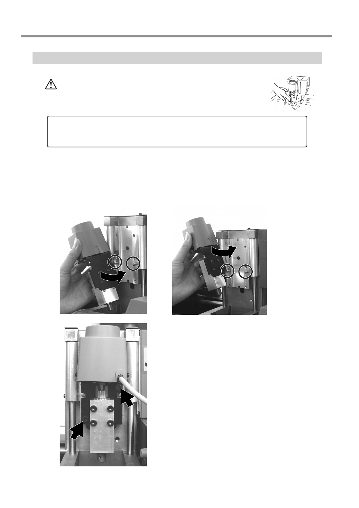
Attach the Spindle Unit
CAUTION
NOTICE
Attach the spindle unit securely so that it does not come loose during cutting.
Before attaching the spindle unit, make sure the power to the Modela is switched o.
Engage the notch on the spindle unit with the area of the carriage shown in the gure, and
During cutting or scanning, keep hands away from the cutting
tool and the probe.
Doing so may result in injury.
press down gently with your hand.
When mounting at the low
position
When mounting at the
high position
22
6 Operation Guide [Cutting Section]
Insert the cap screws at the locations shown in the gure,
and tighten them loosely using the included hexagonal
wrench (size : 3 mm). After attaching all two screws in this
way, tighten them securely.
Page 25
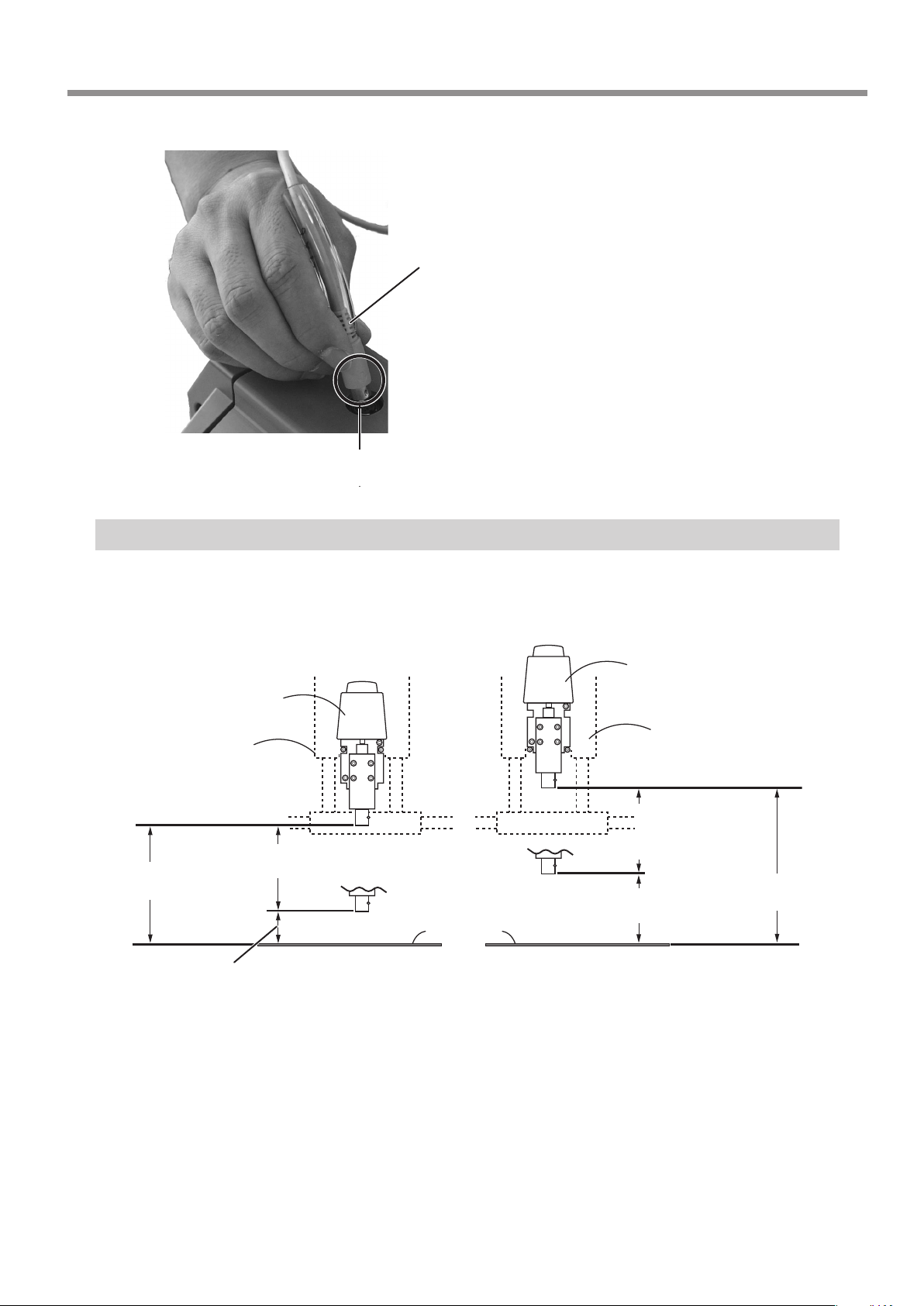
Make sure the tube is at the position shown in the gure.
Insert the cord for the spindle unit into the jack.
Tube
Make sure it is at the base of the cord.
Position the connector so the arrow points
to the back of the unit and insert.
The Mounting Locations for the Spindle Unit
There are two locations (heights) for attaching the spindle unit.
Choose the correct location according to the cutting tool length and the thickness of the workpiece.
Spindle unit
Spindle unit
Carriage
Carriage
Spindle operating
range
Spindle operating range
Approximately
80.6 mm (3-3/16 in.)
Approximately
20 mm (13/16 in.)
Load the workpiece and install the tool. When using a base to load the workpiece, mount the base as well.
Make the layout the same as for actual cutting.
Move the spindle to its highest point. When viewed from the side, if the tip of the tool is lower than the surface of the workpiece, remount the spindle unit at the higher location.
60.5 mm (2-3/8 in.)
Work plate surface
Approximately
56 mm (2-3/16 in.)
60.5 mm (2-3/8 in.)
Approximately
116.5 mm (4-9/16 in.)
6 Operation Guide [Cutting Section]
23
Page 26

Install the Cutting Tool
CAUTION
NOTICE
Attach the cutting tool securely so that it does not come loose during cutting.
To install a cutting tool, remove the spindle. It’s not necessary to remove the whole spindle unit.
Do not touch the tip of the cutting tool with your ngers.
Doing so may result in injury.
While supporting the spindle by hand, remove the screws
at the four places in the gure.
Pull out the spindle from below to remove it.
Spindle
Insert the cutting tool into the spindle.
The cutting tool must not be inserted beyond the shank.
Spindle
Cutting tool
24
6 Operation Guide [Cutting Section]
Page 27
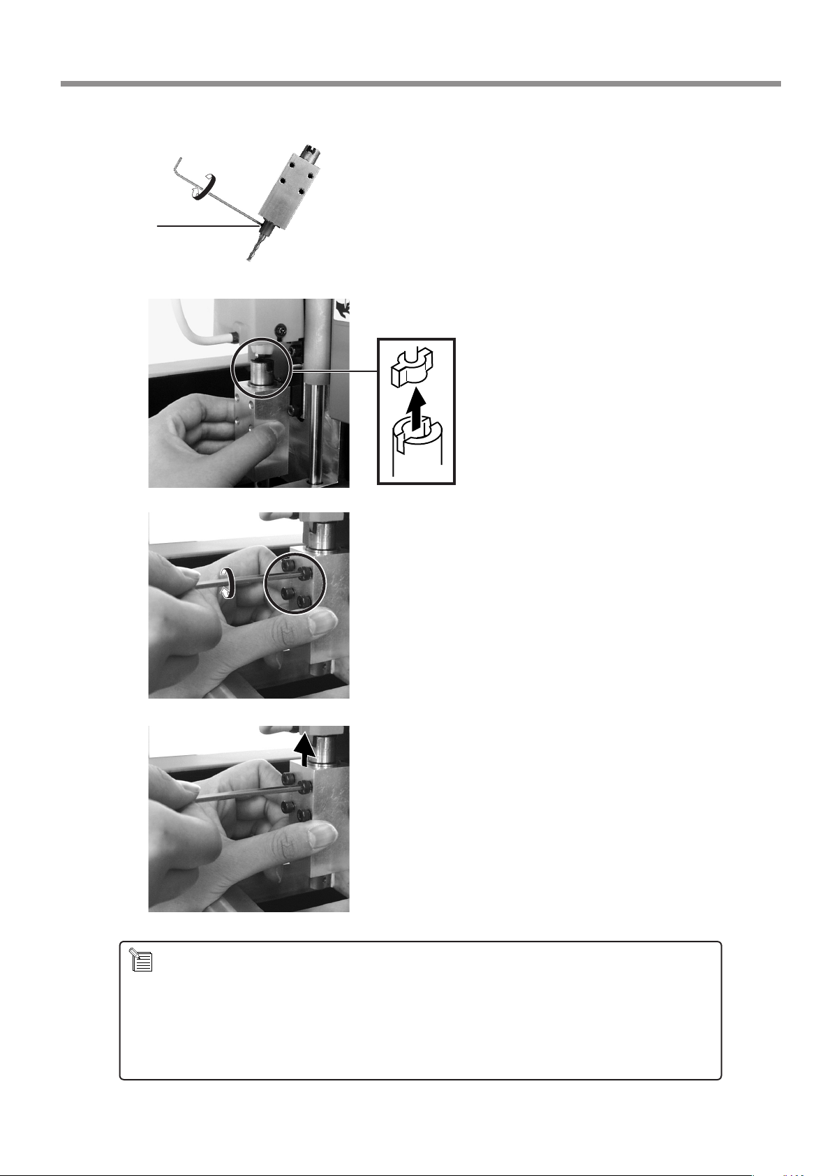
Set screw
Use a hexagonal wrench (size : 1.5 mm) to attach the
included set screws to one side only.
* Insert the set screw straight and install.
Fit the spindle into place as shown in the gure.
Lift up the spindle until it touches, and while holding the
spindle in that position, use the included hexagonal (size :
3 mm) wrench to loosely tighten the screws you removed
in step 1.
About the Length of Tool Extending Beyond the Spindle Tip
Care is required regarding the length of tool extending beyond the spindle for the following reasons:
If too short, the tool tip will not reach the desired depth.
If too long, the tool may strike the workpiece when the tool is raised.
The restricted tool length varies according to the mounting location (height) of the spindle unit and the thickness
of the workpiece. For more information, go to "Attaching the Spindle Unit" and see the gure for "The Mounting
Locations for the Spindle Unit."
After all four screws are in place, While supporting the
spindle by hand, tighten securely.
6 Operation Guide [Cutting Section]
25
Page 28
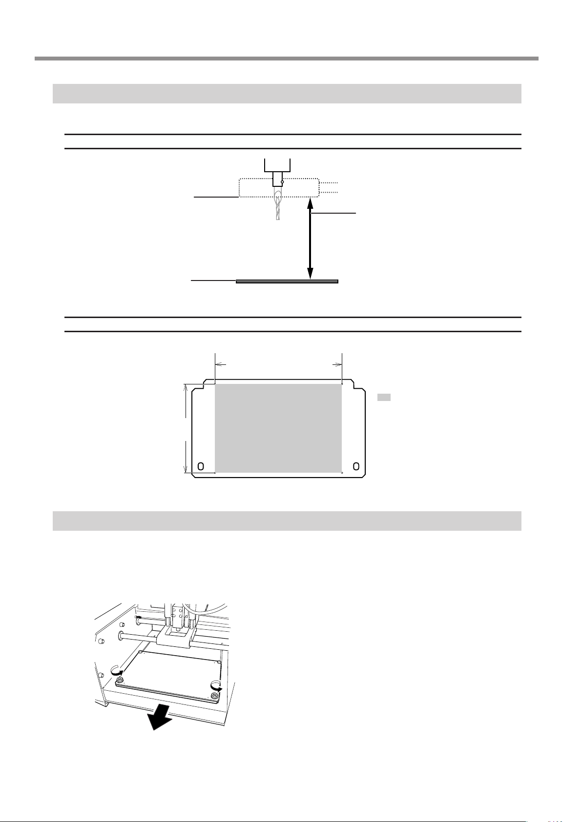
Maximum cutting area of the MODELA
Z-direction
Bottom surface of the carriage
Work plate surface
X- and Y-direction
MDX-20 : 203.2 mm (8 in.)
MDX-15 : 152.4 mm (6 in.)
62.4 mm (2-7/16 in.)
Workpiece thicker than this value cannot
be loaded.
In actual use, the thickness of the loadable workpiece varies according to the
length of the mounted tool and the thickness of the base.
: Maximum cutting area
The area demarcated by lines
MDX-20 : 152.4 mm (6 in.)
MDX-15 : 101.6 mm (4 in.)
passing through the centers
of the four holes as shown in
the gure is the suggested
maximum cutting area.
Load the Workpiece
Prepare a workpiece of the necessary size and load it on MODELA.
A block having a margin of a few millimeters larger than the minimum required size is optimal. Cutting time is long if too
large, and the solid object cannot be made if too small.
Remove the screws shown in the gure and detach the
work plate.
26
6 Operation Guide [Cutting Section]
Page 29
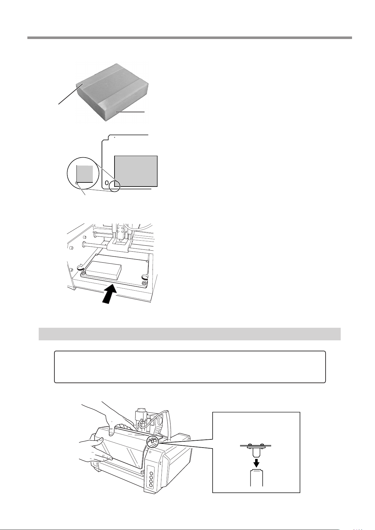
Apply double-sided tape to the workpiece.
Make the adhesive surface broad so that the workpiece does not
come loose during cutting. With a block like that in the gure, for
example, apply the tape so there are no gaps on any side.
Double-sided
tape
Workpiece
Mount the workpiece with its corner aligned with the posi-
tion of the work plate in the gure.
The center of the hole at the lower left of the work plate is the suggested
X- and Y-direction machining reference point for Modela.
Install the work plate.
Press in all the way, until ush.
Attach the Front Cover
NOTICE
Be sure to attach the front cover. If not installed, cuttings may scatter and enter nearby computers or other equipment, resulting in breakdown.
Attach the front cover. If the cover is not attached, the VIEW LED lights (every 1 sec.) up and MODELA does not operate.
Fit the cover plate into place
from above so that it goes
into the portion shown in the
gure.
6 Operation Guide [Cutting Section]
27
Page 30

Powering ON
NOTICE
Before switching on the power to the MODELA, turn on the computer.
Press the STANDBY key.
The STANDBY LED lights up.
The unit performs initial operation and stops, and the VIEW LED and MODELING MODE LED light up.
* During initial operation, a sound may be heard for some 20 seconds at the time of origin detection.
Perform Surfacing
CAUTION
CAUTION
CAUTION
CAUTION
NOTICE
Do not perform cutting using cutting oil. Doing so may result in breakdown.
Wear dust goggles and mask during use.
Cutting dust may scatter, causing bodily injury.
During cutting or scanning, do not place hands near the cut-
ting tool or the probe.
Doing so may result in injury.
Do not allow children to operate without adult supervision
or operate within reach of young children.
Doing so may result in injury.
Do not operate if a transparent cover is cracked or broken.
If the transparent cover at the front or the side of the unit is
cracked, contact a service agent immediately for repairs.
28
6 Operation Guide [Cutting Section]
Page 31

Cut the surface of the loaded workpiece to eliminate unevenness and create a level surface.
This is called "surfacing."
1.
Set the Depth-direction Reference point
Set the depth-direction reference point on the top surface of the workpiece.
MODELA takes the position of the tool just before starting cutting as the depth-direction reference point.
* You cannot set this while the VIEW LED is lit or during cutting.
While the VIEW LED is lighted, pressing the key cancels
the paused state.
The carriage moves to MODELA's X- and Y-direction machining
reference point.
Hold down the TOOL-DOWN key to lower the cutting tool
to close to the surface of the workpiece.
The cutting tool rotates as
it descends
Workpiece
When the tool tip comes close to the workpiece surface, carefully use the key to lower the
cutting tool a little at a time.
When the tip touches the workpiece, release the TOOLDOWN key.
After setting the reference point, do not press the TOOL-UP or TOOLDOWN keys.
Cutting tool
Workpiece
2.
Verify the Cutting Position and Height When the Tool Is Lowered
Use MODELA Player to move the MODELA tool, then verify the following two points.
- Object Cutting Position
Make sure that the cutting position specied with MODELA Player matches the position of the workpiece loaded
on the Modela.
- Height When Tool Is Lowered
Move the tool, and verify the height when the tool is lowered to the depth-direction reference point.
If the height of the workpiece is not uniform, cutting deeper than the surface of the workpiece may be performed
when the tool is lowered to a position other than the position set for the depth-direction reference point. If this
happens, then set the depth-direction reference point again.
6 Operation Guide [Cutting Section]
29
Page 32

From the [Options] menu, click [Layout...].
The [Layout/Surfacing] dialog box appears.
Black circles
Blue rectangle
If the workpiece is cut when you lower the cutting tool at positions 1 through 3 in step 2,
then skip ahead to the next section, "3. Reset the Depth-direction Reference Point."
If it is not cut, then proceed to step 2 of "4. Perform Surfacing" and perform surfacing.
To make the setting for the cutting position only without performing surfacing, then click
[OK].
3.
Reset the Depth-direction Reference Point
The blue rectangle is the range of the object.
When you double-click one of the black circles displayed
at the corners of the object, the cutting tool descends to
the depth-direction reference point at that location.
Double-click black circles in the sequence shown by the
numbers in the gure and verify the cutting position.
To move the object's cutting position, drag the blue rectangle.
In "2 verify the specied cutting position and the height when the tool is lowered," if the tool cut the surface of
the workpiece, then you need to redo the setting.
Reset the depth-direction reference point at the highest position on the workpiece.
If surfacing is started without redoing the setting rst, then the amount of cutting in the rst pass increases, which
may place excessive load on the tool and make it impossible to complete surfacing.
Cutting tool
Amount cut in
rst pass
Workpiece
OK
Depth-direction
reference point
Amount of
surfacing
Amount cut in
rst pass
Cutting tool
Workpiece
Not OK
30
6 Operation Guide [Cutting Section]
Page 33
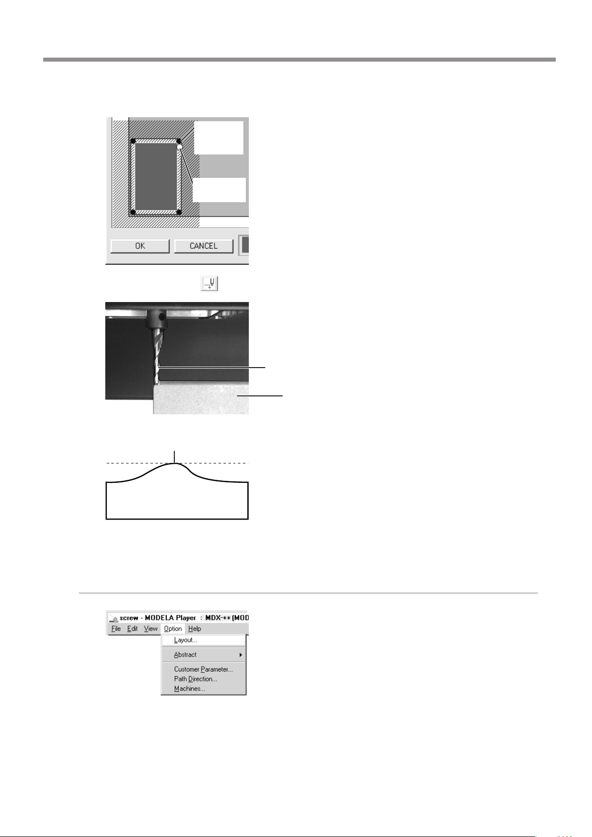
Press the TOOL-UP key to move the cutting tool away from the workpiece.
When you click the button, the cutting tool moves to the white circle.
Place cut
deeper than
the surface
Move the
white circle
In MODELA Player's [Layout/Surfacing Settings] dialog
box, In the dialog box, drag the white circle to move it
next to the black circle where you performed cutting in
"2. Verify the Cutting Position and Height When the Tool
Is Lowered." In this example, it's assumed that the black
circle shown in the gure was cut.
Press the TOOL-DOWN key.
Release the key when the tip of the cutting tool touches
the surface of the workpiece.
The depth-direction reference point has now been reset.
Cutting tool
Workpiece
4.
Redo the setting at the
high location
Perform Surfacing
Lower the cutting tool at the four remaining corners with
the new reference point, and make sure that the workpiece
is not cut. (See "2. Verify the Cutting Position and Height
When the Tool Is Lowered" in the previous section.) If the
workpiece is cut, then repeat steps 2 and 3 and set a new
reference point.
* When you view the loaded workpiece edge-on from the side, if
there is any location higher than the four corners, then move the
cutting tool to that location and redo the setting for the depthdirection reference point.
From MODELA Player's [Option] menu, click [Layout].
The [Layout/Surfacing Settings] dialog box appears.
6 Operation Guide [Cutting Section]
31
Page 34
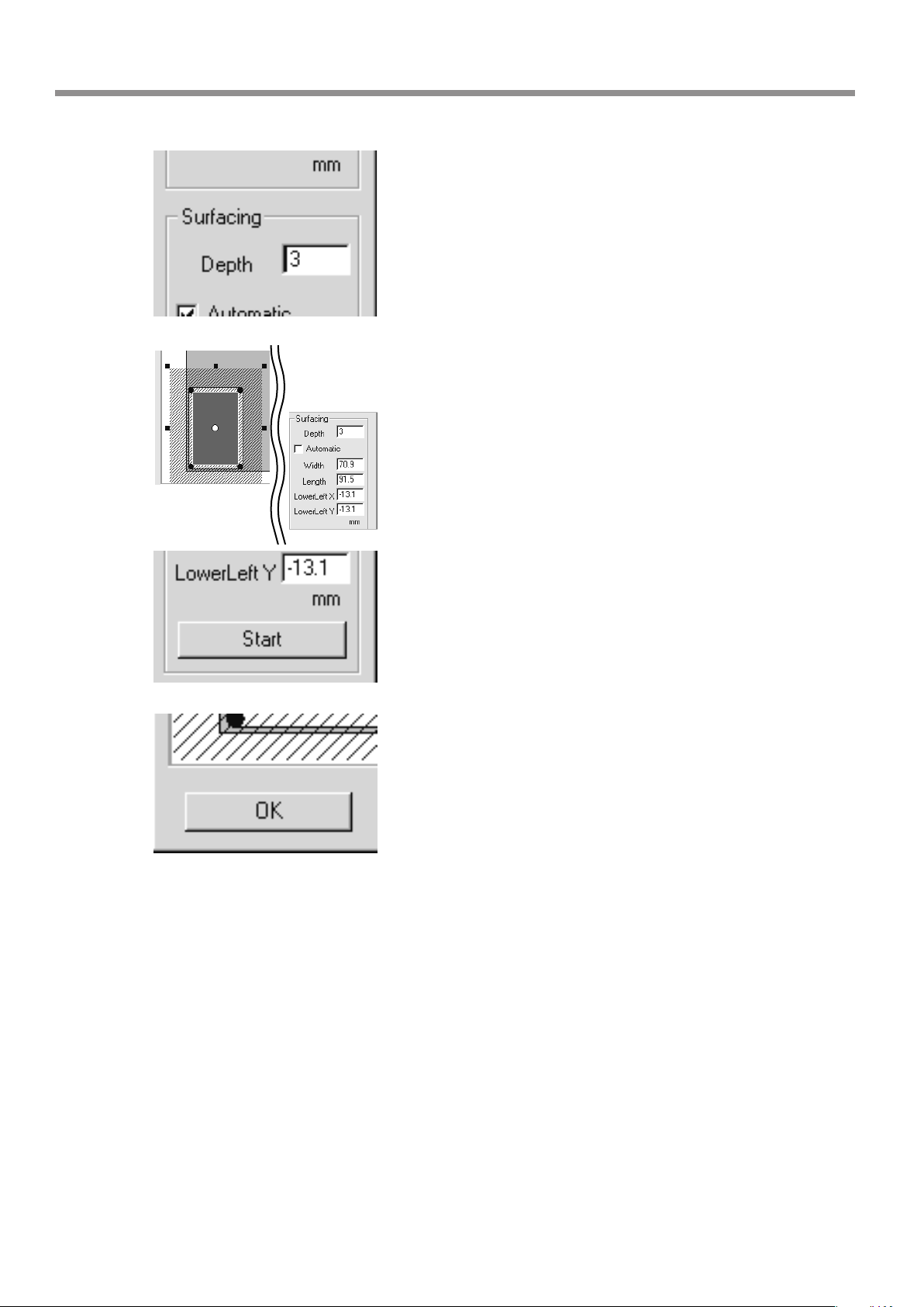
Enter the surfacing depth.
Here you set the cutting depth from the depth direction reference
point.
To change the range and location for surfacing, clear the
selection for [Automatic].
To change the range, drag the solid squares surrounding
the shaded area, or type in numerical values for [Width]
and [Length].
To change the location, drag the shaded portion or type in
numerical values for [Lowerleft X], [Lowerleft Y].
Click [Start] to start surfacing.
When surfacing ends, the depth-direction reference point is set at
the surface after surfacing.
When surfacing ends, click [OK].
32
6 Operation Guide [Cutting Section]
Page 35
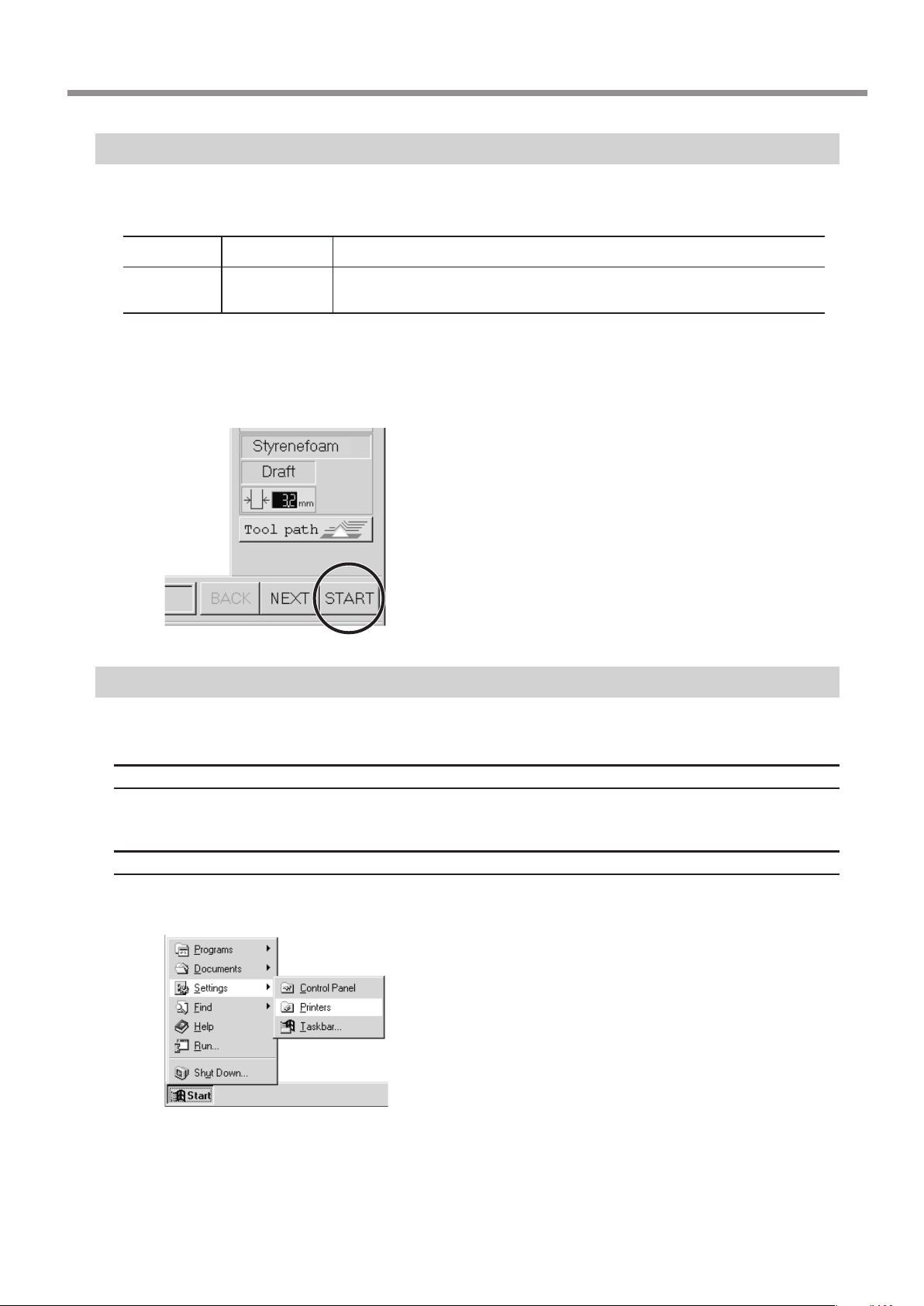
Perform Cutting
A three-dimensional object is cut in two stages: draft cutting and nishing.
First pass
Second
pass
When nishing ends, cutting is complete.
Depending on the composition of the workpiece, however, nishing may not actual produce an attractive nish.
In such cases, use a le or the like to work it by hand.
Draft cutting
Finishing
High-speed cutting that leaves a margin for nishing
High-precision cutting of the margin on the workpiece surface left by draft cutting
Click [START] to start cutting.
Pausing or stopping operation
Press the VIEW key to quit the cutting operation.
To continue with cutting
Press the VIEW key again.
To end cutting
Stop sending data from MODELA Player.
Open the [Printers] folder.
Windows 95/98/Me/NT4.0/2000:
Click [Start]-[Settings]-[Printers].
Windows XP:
Click [Start]-[Control Panel]. Click [Printers and Other
Hardware], then click [Printers and Faxes].
6 Operation Guide [Cutting Section]
33
Page 36
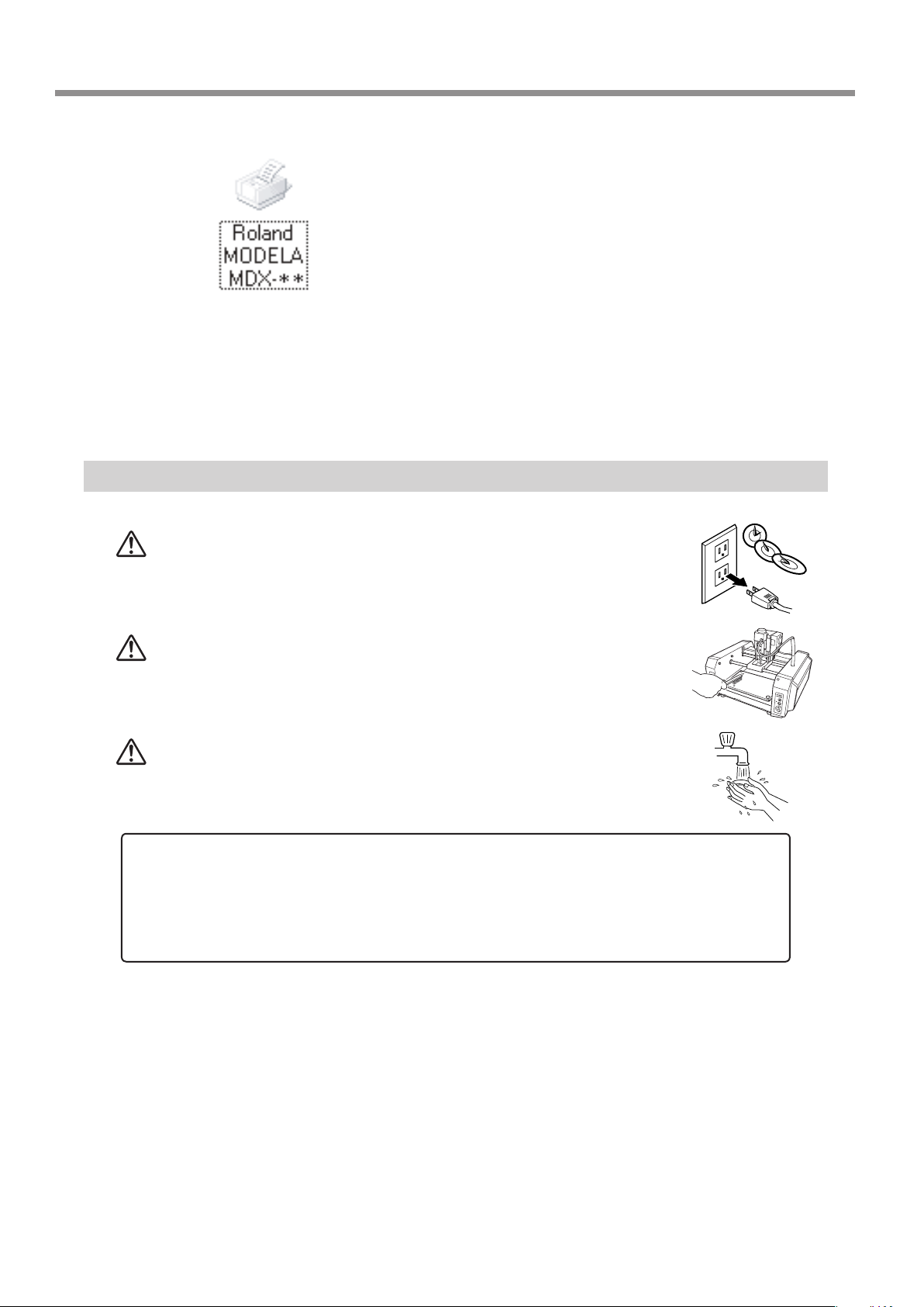
At the [Printer] menu, choose [Purge Print Jobs] or [Cancel] to stop sending data.
If you're using Windows 2000/XP, choose [Cancel All Documents].
To delete cutting data remaining in MODELA, press the Modela TOOL-UP and TOOL-
DOWN keys at the same time.
The VIEW LED ashes. When the LED stops ashing, deletion is nished.
When Cutting is Finished
Double-click the printer icon for the machine you're using.
If you're using the MDX-20, double-click the [MODELA MDX-20]
icon. If you're using the MDX- 15, double-click the [MODELA MDX15] icon.
CAUTION
CAUTION
CAUTION
NOTICE
Be sure to also remove any buildup of cuttings under the machine. Continuing to use the machine without removing cuttings may result in built-up cuttings getting inside the mechanism, leading to breakdown.
Do not use an air blower to remove cuttings by blowing them away. The cuttings may get inside the mechanism,
resulting in breakdown.
* Be sure to remove cuttings only after MODELA has nished cutting.
When not in use for several hours, unplug the power-cord
plug from the electrical outlet.
Failure to do so may result in danger of shock, electrocution,
or re due to deterioration of the electrical insulation.
Use a commercially available brush to remove metal cut-
tings.
Attempting to use a vacuum cleaner to take up metal cuttings
may cause re in the vacuum cleaner.
When you're nished, wash your hands to rinse away all
cuttings.
34
Press the STANDBY key to switch off the power.
Remove the workpiece you have nished cutting.
If the workpiece does not peel o easily, use commercially available ethyl alcohol and a wooden spatula
or the like to remove it.
6 Operation Guide [Cutting Section]
Page 37
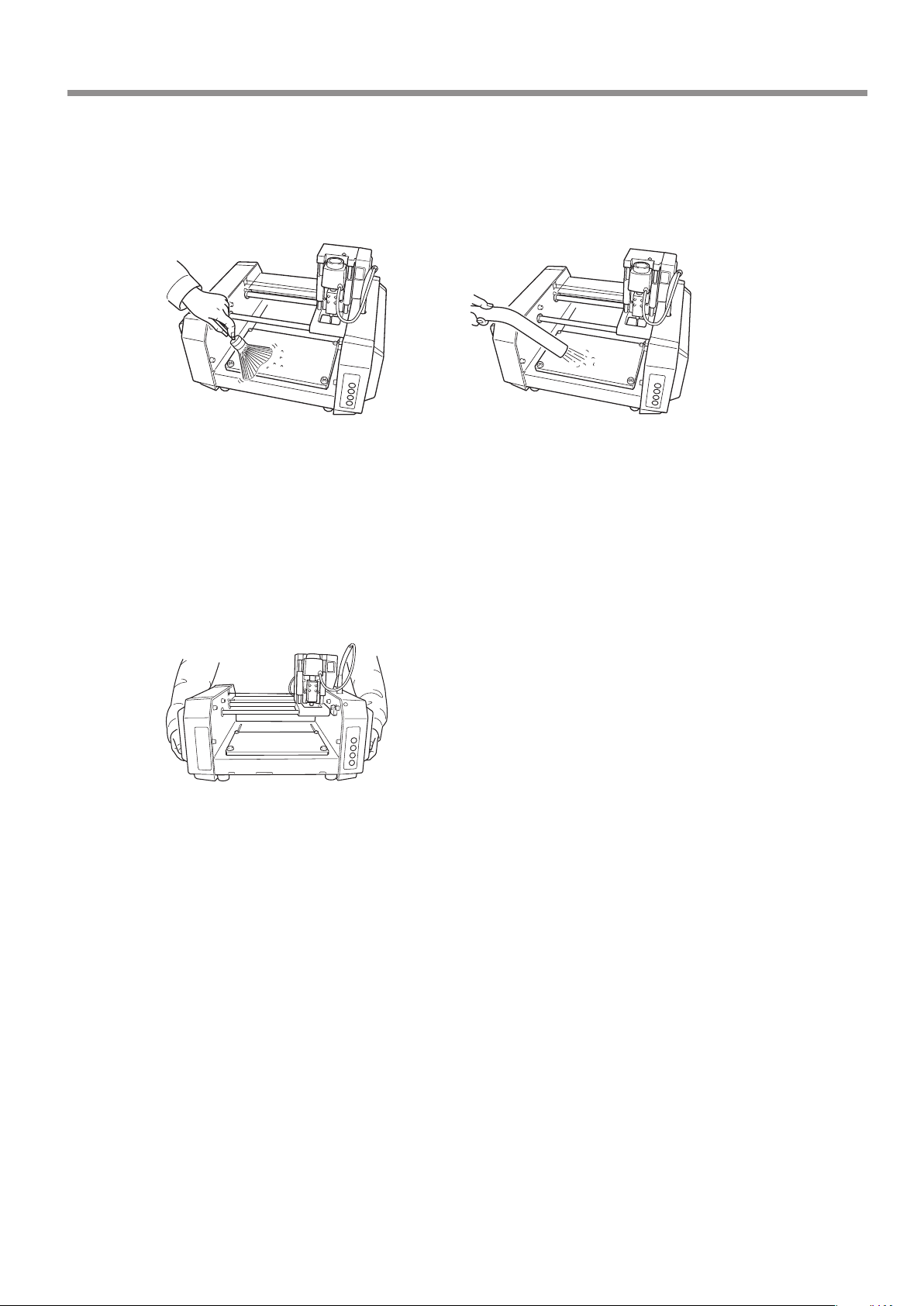
Remove fallen cuttings from around the workpiece and the table.
Metal cuttings
Remove using a commercially
available brush.
Remove any buildup of cuttings from under the table.
Metal cuttings
Detach the work plate.
While holding down the STANDBY key, switch on the power to MODELA.
Press the VIEW key and move the table. Use a commercially available brush to remove
any metal cuttings that are exposed.
After removing the cuttings, hold down the STANDBY key and switch off the power.
Other cuttings
Detach the work plate and use a vacuum cleaner to take up any cuttings.
Other cuttings
Remove using a commercially available
brush or with a vacuum cleaner.
Unplug the power-cord plug from the electrical outlet.
Lift up MODELA and also remove any cuttings that may
have fallen underneath.
6 Operation Guide [Cutting Section]
35
Page 38

7 Operation Guide [Scanning Section]
Step 1: Attach the Sensor Unit
NOTICE
Attach the sensor unit securely so that it does not come loose during cutting.
Perform installation and removal of the sensor unit while the cover is attached. If the cover is not present, the
probe may be damaged if the sensor unit should fall or be dropped.
Before attaching the spindle unit, make sure the power to the Modela is switched o.
If the spindle unit is installed on the carriage, then remove
it. Do this by following the steps in “Attach the Spindle Unit”
in reverse order.
Engage the notch on the sensor unit with the area of the
carriage shown in the gure, and press down gently with
your hand.
36
7 Operation Guide [Scanning Section]
Insert the cap screws at the locations shown in the gure,
and tighten them loosely using the included hexagonal
wrench (size : 3 mm). After attaching all four screws in
this way, tighten them securely.
Page 39
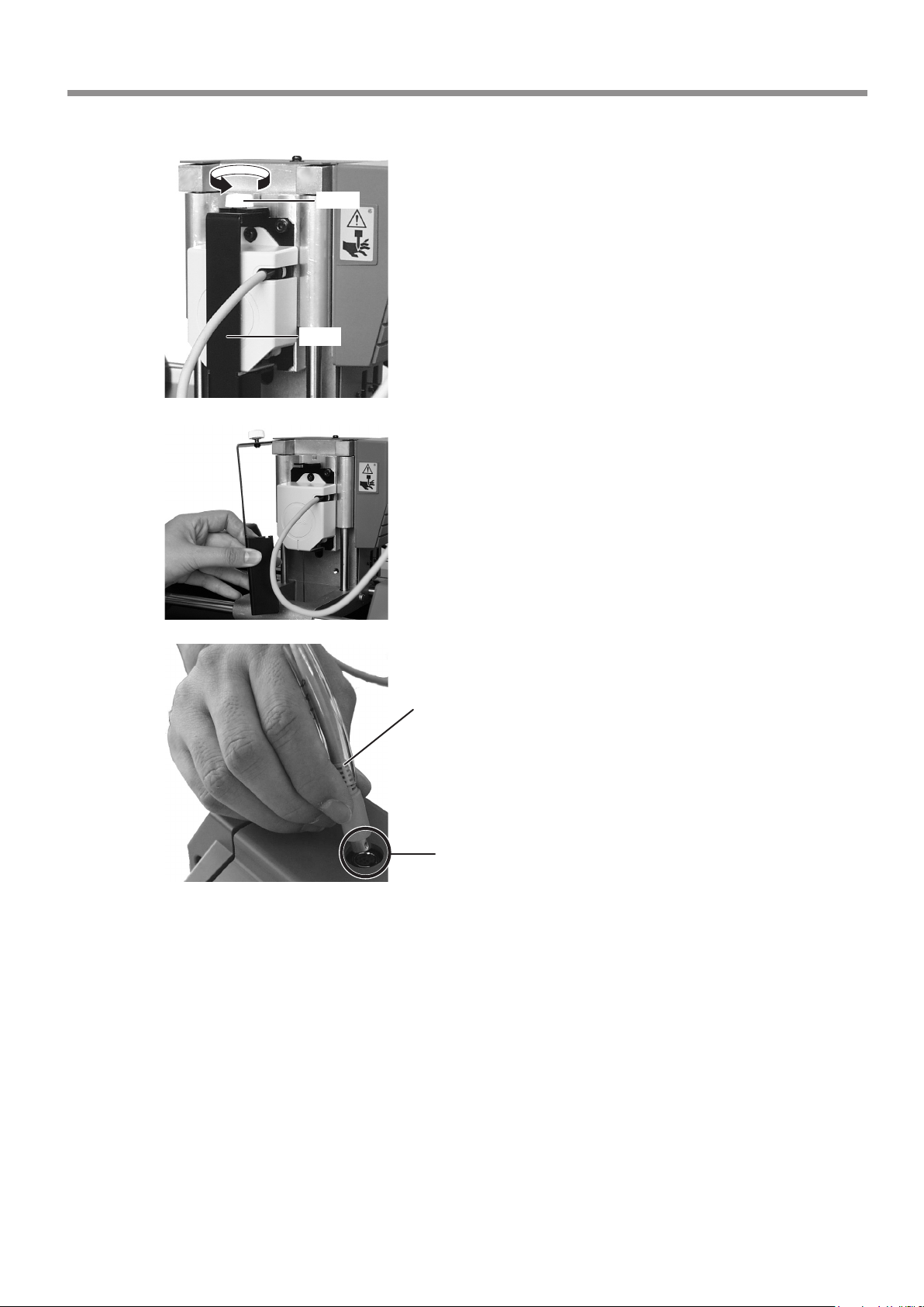
While gently pressing down on the cover with one hand,
loosen the screw shown in the gure.
Screw
Cover
Pull the cover back to remove it.
Make sure the tube is at the position shown in the gure.
Insert the plug for the sensor unit into the jack.
Tube
Make sure it is at the base of the cord.
Position the connector so the arrow points
to the back of the unit and insert.
7 Operation Guide [Scanning Section]
37
Page 40

Detaching the Sensor Unit
Fit the cover onto the sensor unit as shown in the gure.
Screw
Cover
Cover
Sensor unit
Cover
Fit the notch in
the cover into the
area shown by
slanted lines.
Sensor unit
While gently pressing down on the cover with
one hand, tighten the screw shown in the
gure.
Remove the sensor unit by following steps 2, 3, and 6 of "Attach the Sensor
Unit" in reverse order.
Step 2: Load the Object to Be Scanned on the MODELA
The sensors for the MODELA are highly sensitive, and can even scan three-dimensional objects made out of clay.
You can usually perform scanning if the three-dimensional object is of a composition and conguration that can retain its
shape.
However, the pressures that the sensors detect are from several grams to several tens of grams, so you cannot scan objects
whose shape changes when touched by the sensors. (Pressure may uctuate, depending on the composition of the object
being scanned.)
For instance, it may not be possible to scan something like a fuzzy stued animal or rubber.
Depending on the shape you're scanning, a maximum error equal to the radius of the probe (0.5 mm) may occur.
38
7 Operation Guide [Scanning Section]
Page 41
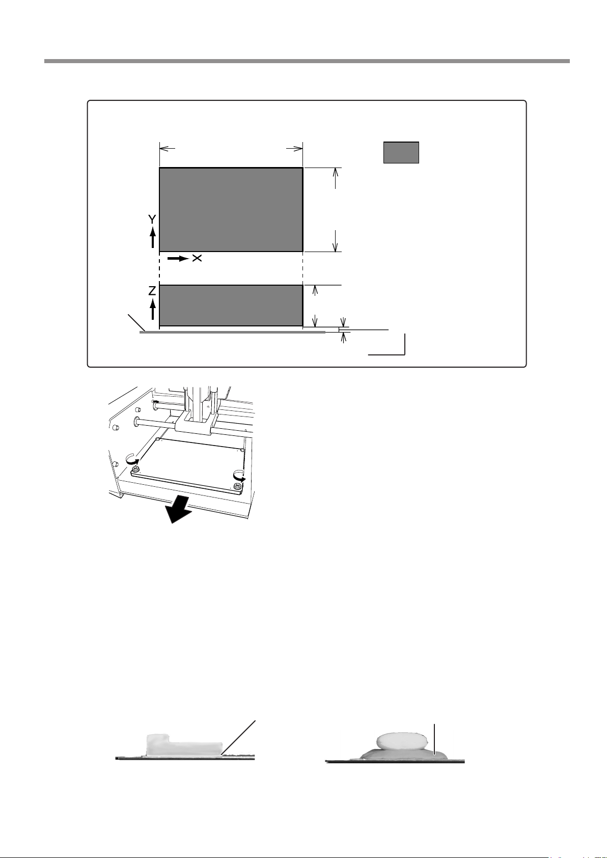
Maximum scanning area of the MODELA
The maximum scanning area is shown in the gure.
Work plate
MDX-20 : 203.2 mm (8 in.)
MDX-15 : 152.4 mm (6 in.)
* This space cannot be scanned.
Remove the screws shown in the gure and detach the
work plate.
Maximum scaning area
MDX-20 : 152.4 mm (6 in.)
MDX-15 : 101.6 mm (4 in.)
60.5 mm (2-3/8 in.)
1 mm (0.0394 in.)
Orient so the surface with the grid faces up.
Mount the object to be scanned.
Secure the object to be scanned in place on the work plate for scanning.
Mount the object to scan securely in place so that it does not move during scanning.
The grid on the table serves as a guide for mounting the object to scan. It does not indicate the scanning
area for Dr. PICZA. The scale is in 10 mm (3/8 in.) units.
When the shape has a at bottom
and is easy to secure in place
Secure in place with
double-sided tape.
When the bottom is uneven and difcult to secure
in place
When scanning as far as the bottom surface of
the object to be scanned
Make a base using clay, and press
the object into the clay base from
above to secure it in place.
7 Operation Guide [Scanning Section]
39
Page 42
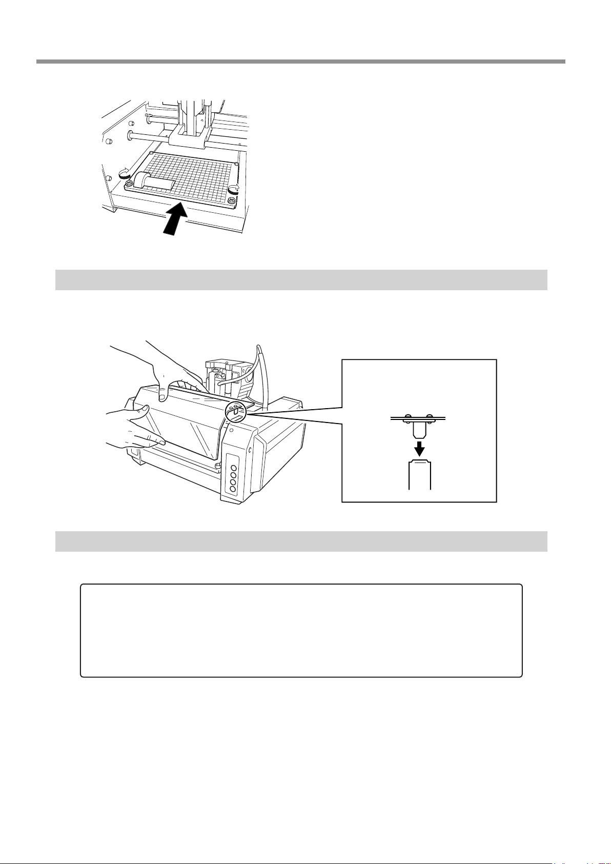
Press in all the way, until ush.
Install the work plate on MODELA and tighten the
screws.
Step 3: Attach the Front Cover
Attach the front cover.
Fit the cover plate into place
from above so that it goes
into the portion shown in the
gure.
40
Step 4: Powering ON
NOTICE
Before switching on the power to the MODELA, turn on the computer.
Press the STANDBY key.
The STANDBY LED lights up.
The unit performs initial operation and stops, and the SCANNING MODE LED lights up.
7 Operation Guide [Scanning Section]
Page 43
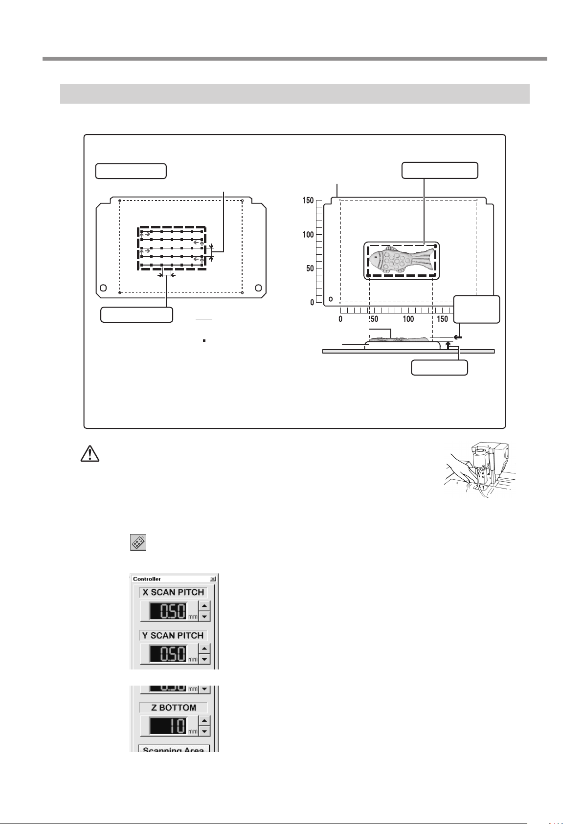
Step 5: Setting Scanning Conditions and Starting Scanning
About scanning conditions and the scanning area
Y SCAN PITCH
(Spacing of adjacent scan points along the Y axis)
Scanning area
X SCAN PITCH
(Spacing of adjacent scan
points along the X axis)
: Scan path
(bidirectional scanning)
: Scan points
Workpiece
plate
Scan object
Cray
Workpiece
plate
* If you have made a clay base, the height of the
clay is taken to be the Z-axis reference surface.
Scanning Area
Z Upper
Limit
Z BOTTOM
(Height of the scanning
area's bottom plane)
CAUTION
Start Dr. PICZA and make the settings for scanning resolution, the lower limit for the height of the surface to scan, and the
scanning quality.
Click on the Dr. PICZA.
The Controller window opens. When Dr. PICZA is started, the Controller window is already open.
During cutting or scanning, keep hands away from the cut-
ting tool and the probe.
Doing so may result in injury.
Make the settings for X scan pitch and Y scan pitch.
Make the setting for Z bottom.
If you have made a clay base, the height of the clay is taken to be
the Z-axis reference surface.
7 Operation Guide [Scanning Section]
41
Page 44

Make the selection for scanning quality.
Select [Smart Scan]. When this is selected, MODELA
identies and limits the scanning area before performing
scanning (X and Y directions only).
To specify the scanning area manually, deselect [Smart
Scan], then click [Set Scanning Area].
For more information on how to specify this, see “Setting the Scanning Area” in the next section.
For detailed description of the available Controller buttons, please
refer to the help screens for Dr. PICZA.
Click [SCAN] .
Scanning starts.
(During scanning, the sensor may emit a transmission sound, but
this is normal.)
If You’re Using Windows NT4.0/2000/XP
If the printer port for the Windows driver and the communication port for Dr. PICZA are set to the same port, you cannot use
Dr. PICZA. To perform scanning, you need to temporarily set the Windows driver printer port to a dierent port. After you
nish scanning, return the setting for the Windows driver to its original value.
Use the following examples as a guide to determine the amount of computer memory required to perform scanning.
* The gures shown below are the amounts used by Dr. PICZA alone. They do not take into account the amounts used by
the operating system or other programs.
Example: Required memory when scanning a 100 mm x 100 mm (3-15/16 in. x 3-15/16 in.) area
- Scanning at a pitch of 0.05 mm x 0.05 mm (0.002 in. x 0.002 in.) : Approx. 2 GB
- Scanning at a pitch of 0.1 mm x 0.1 mm (0.004 in. x 0.004 in.) : Approx. 500 MB
- Scanning at a pitch of 0.5 mm x 0.5 mm (0.020 in. x 0.020 in.) : Approx. 20 MB
Step 6: Setting the scanning area
If you wish to limit the scanning area, such as in cases where you wish to scan only a portion of an object, make the settings
as described below.
Click in the Controller window.
The [Scanning Area] dialog box appears.
42
7 Operation Guide [Scanning Section]
Page 45
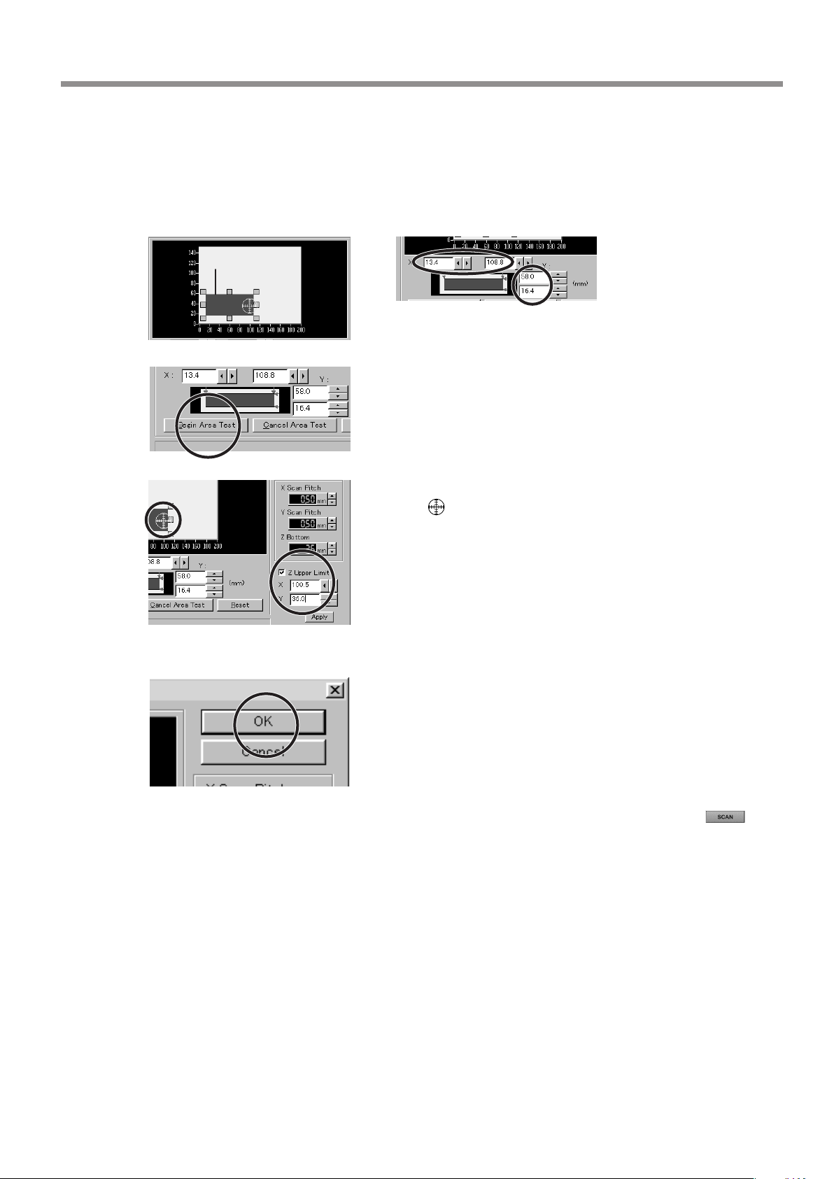
Make the settings for the scanning area.
Make the settings to match the location where the scan object is secured in place.
Either of the following two methods can be used to make the settings.
- Use the mouse to move the blue
frame on screen.
Blue frame
- Enter the numerical values for the
upper-right and lower-left points.
The size of the on-screen scanning area (shown in blue) changes to
match the values that are entered.
Click [Begin Area Test].
The sensor moves to a position above an outer point on the scanning
area that has been set.
Make sure the scan object that has been secured in place lies within
the area.
Click [Z Upper Limit].
The cursor is displayed on the Z upper-limit setting on screen.
Specify the highest position of the scan object.
Clicking [Apply] or double-clicking on the target lowers the sensors to the target's center position. If the target is displaced, redo
the settings.
* Set the Z upper limit to the highest position on the object to be
scanned. During scanning, if the sensor detects a position higher
than the Z upper-limit setting, the setting is cleared and scanning
continues with the greatest scan height of Dr. PICZA as the Z upper
limit.
Check the scanning conditions in the Controller window one more time, then click .
Scanning starts. (During scanning, the sensor may emit a transmission sound, but this is normal.)
- For the scanning area and Z upper limit, please refer to "7 Operation Guide [scanning section] About
scanning conditions and the scanning area".
- For detailed description of the available Controller buttons, please refer to the help screens for Dr.
PICZA.
After determining the scanning area, click [OK].
7 Operation Guide [Scanning Section]
43
Page 46
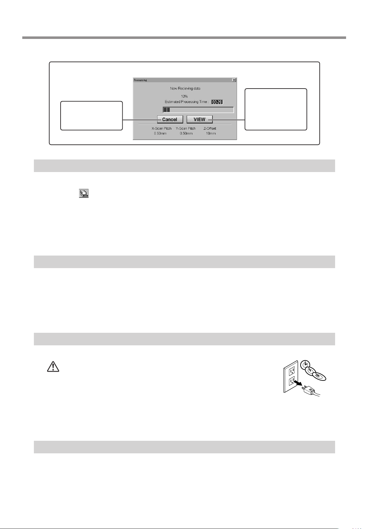
Cancels scanning/Pauses scanning
Cancels scanning.
Any data scanned
before being canceled
remains in memory.
Step 7: Saving Scanned Data
Click and choose [Save].
The [Save As] dialog box appears.
Choose the desired location for saving the le, enter a le name, and click [SAVE].
The extension ".pix" is appended to the le name.
If you want to export the data as a le in DXF or VRML format, please refer to the help screens for Dr.
PICZA.
Scanning pauses
and the table moves
toward the front of
the unit. Click [VIEW]
again to resume scanning.
Step 8: Edit the Scanned Data
The shape of an object can be edited. It is possible to vary the height, adjust the slant, or perform concave/convex inversion
(height inversion) for a desired surface.
You can use the toolbar button or select [Edit] on the menu bar.
Please refer to the help screens for Dr. PICZA for detailed explanations of the various functions that are available.
Be sure to save the scanned data before starting to edit. When you're done editing, be sure to save your le.
When Scanning Is Finished
CAUTION
Press the STANDBY key to switch off the power.
Remove the scan object from the table.
When not in use for several hours, unplug the power-cord
plug from the electrical outlet.
Failure to do so may result in danger of shock, electrocution,
or re due to deterioration of the electrical insulation.
44
When not in use
- Remove any clay from table, and store the clay so that it will not dry out.
- Unplug the power-cord plug from the electrical outlet.
7 Operation Guide [Scanning Section]
Page 47

8 Overview of the Usage Guides
Overview of the Usage Guides
The included Roland Software Package CD-ROM contains the following PDF les.
- Cutting Tips
This describes tips and tricks for double-sided cutting and methods for securing the workpiece in place.
- Scanning Tips
This describes how to shorten scanning times and perform rescanning.
Location of the Usage Guides
The usage guides are found at the following locations.
View the following les directly from the CD-ROM, or copy the following les to your hard disk and read them from there.
Cutting Tips : [Document] - [Cuttips] - [Cuttip-e.pdf]
Scanning Tips : [Document] - [Scantips] - [Scatip-e.pdf ]
Installing the Acrobat Reader
Acrobat Reader is required to view PDF les.
If Acrobat Reader is not set up on your computer, you need to set it up.
The included CD-ROM also contains Acrobat Reader.
[Acrobat] - [English] - [ar405eng.exe]
(This runs under Windows 95 or later.)
8 Overview of the Usage Guides
45
Page 48
9 Software Guide
This describes the general procedures for software you can use with MODELA.
For detailed descriptions, take a look at the help screens for the respective software.
* The explanations in this section describe operation of the MDX-20. If you're using the MDX-15, then where "MDX-20" ap-
pears in the text, read "MDX- 15" instead.
Driver for Windows 95/98/Me
This section explains how to make the settings for the engraving parameters.
When sending data from Dr. Engrave or a commercially available drawing program, the driver sets engraving parameters such
as the tool’s operating speed, depth, and pitch. When sending data from MODELA Player or 3D Engrave to MODELA, the data
is sent to the driver’s output port. At this time, all driver settings other than the port are ignored, and do not aect cutting.
Display the Driver Setting Screen
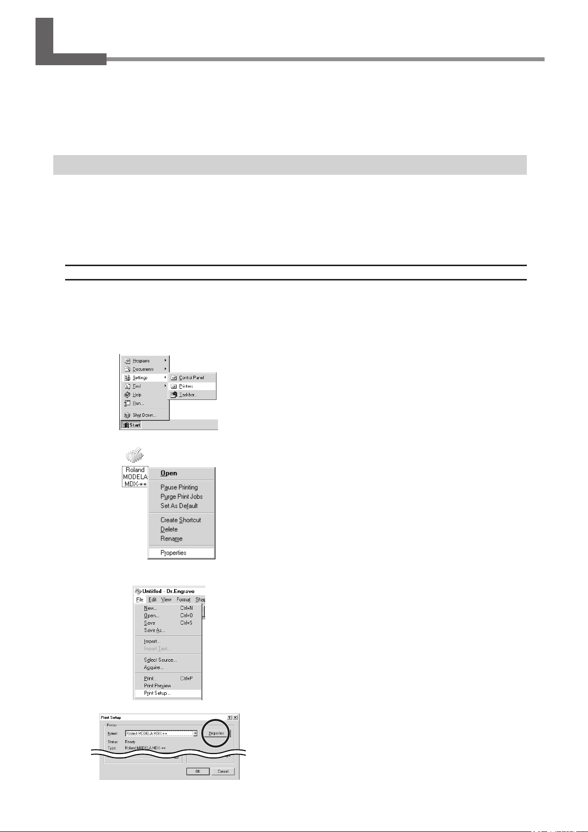
To make the settings for the driver, open Properties. You can use either of the two methods described below to open Properties.
Method 1
When you use this method to make the settings, any changes you make in Properties also aect other Windows-based
programs.
Method 2
Click [Start]. Point to [Settings] and click [Printer].
The [Printers] folder appears.
Right-click on the [Roland MODELA MDX-20] icon, then
click [Properties].
From the [File] menu, click [Print Setup...].
The [Print Setup] dialog box appears.
46
9 Software Guide
Set the printer to [Roland MODELA MDX-20], then click
[Properties].
Page 49

Enter the Cutting Area
Enter the size of the plate installed on MODELA.
Set the Engraving Parameters
Make the settings for the composition of the workpiece to engrave and the engraving depth.
Choosing the composition sets engraving parameters suited to this engraving. However, [Z Down Position] and [Fill Pitch]
are determined with no relation to composition, and so they are set separately. For [Z Down Position], enter the engraving
depth. For [Fill Pitch], enter the tool diameter.
The values for settings other than [Z Down Position] and [Fill Pitch] are also suggested guidelines. If the results of actual
engraving are not as expected, modify the values accordingly.
Lines are distinguished by color, and parameters when engraving a line of the corresponding color are set.
Click the [Size] tab.
Enter values for [Width] and [Length].
Click the [Tool] tab.
Click the drop-down arrow for [Material], then click the
composition of the engraving material (workpiece).
Click the tab for the color to set.
The numeral appearing next to the color is the tool number that is
now set.
Click the drop-down arrow for [Tool], then click the tool
number.
If you don’t wish to engrave lines of that color, click
[None].
9 Software Guide
47
Page 50
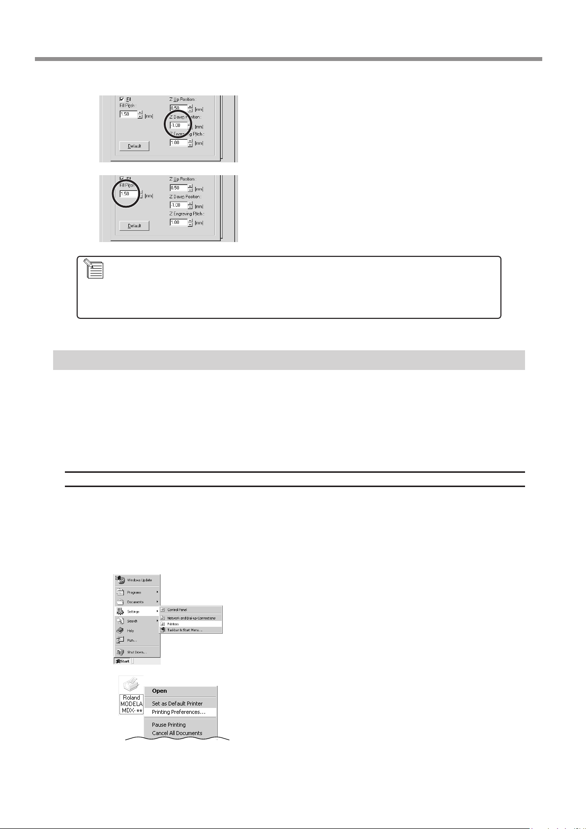
For [Z Down Position], enter the cutting-in depth.
For [Fill Pitch] and items other than [Fill Pitch], suitable values are set for engraving the composition you chose in
step 2. However, these values are only suggestions. If the results of actual engraving are not as expected, adjust
the values accordingly.
For [Fill Pitch], enter the diameter of the tool tip.
To achieve an attractive nish, enter a value narrower than the
actual diameter.
Driver for Windows NT4.0/2000/XP
This section explains how to make the settings for the engraving parameters.
When sending data from Dr. Engrave or a commercially available drawing program, the driver sets engraving parameters such
as the tool’s operating speed, depth, and pitch. When sending data from MODELA Player or 3D Engrave to MODELA, the data
is sent to the driver’s output port. At this time, all driver settings other than the port are ignored, and do not aect cutting.
To make the settings for the Windows NT4.0/2000/XP driver, log on to Windows as "Administrators" or "Power Users" account.
Display the Driver Setting Screen
To make the settings for the driver, open Properties. You can use either of the two methods described below to open Properties.
Method 1
When you use this method to make the settings, any changes you make in Properties also aect other Windows-based
programs.
Open the [Printers] folder.
Windows NT4.0/2000:
Click [Start]-[Settings]-[Printers].
Windows XP:
Click [Start]-[Control Panel]. Click [Printers and Other
Hardware], then click [Printers and Faxes].
Windows NT4.0:
Right-click the [Roland MODELA MDX-20] icon, then click
[Document Defaults].
Windows 2000/XP:
Right-click the [Roland MODELA MDX-20] icon, and click
[Printing Preferences]. Then, click [Advanced].
48
9 Software Guide
Page 51
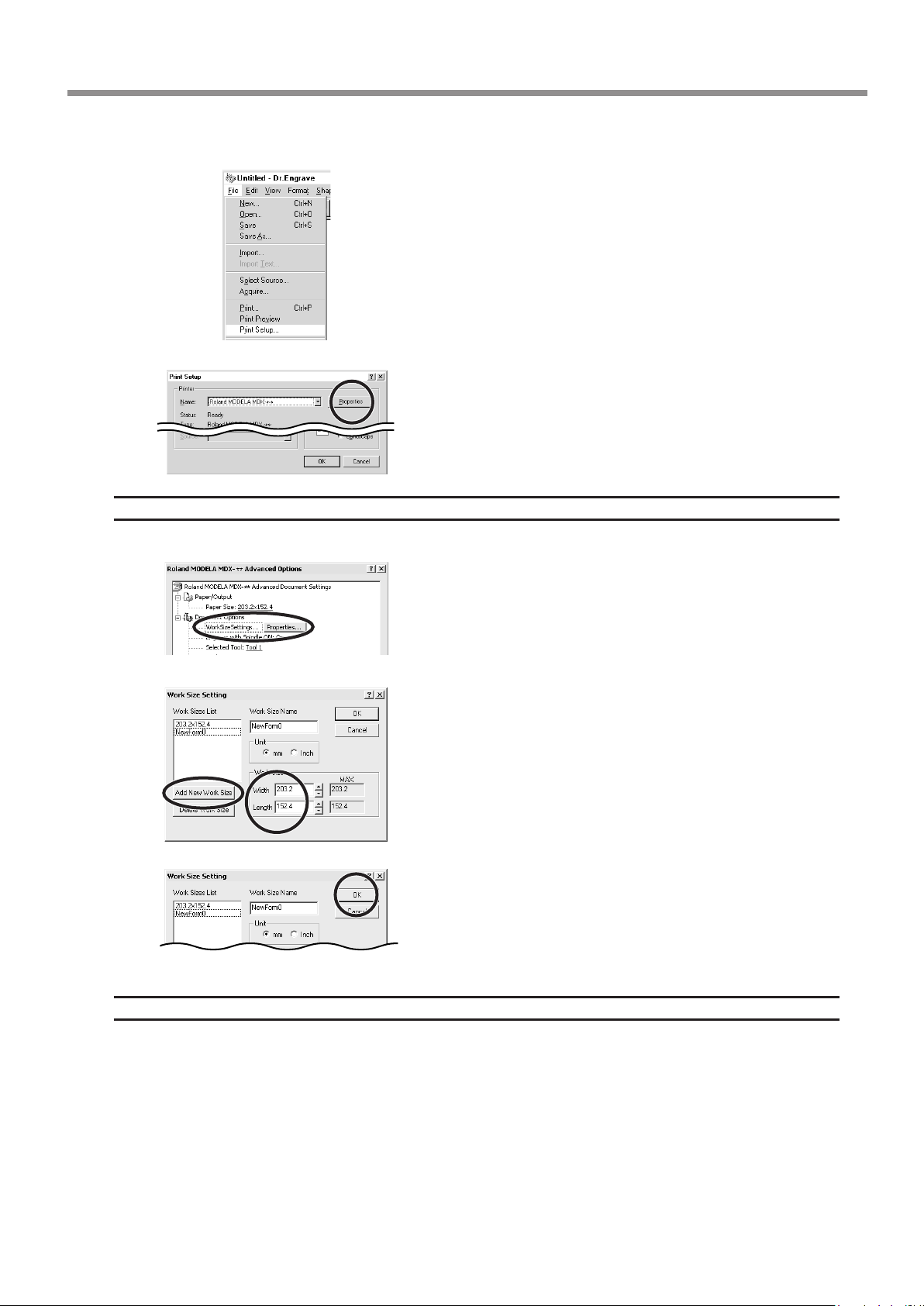
Method 2
Enter the Cutting Area
Enter the size of the plate installed on MODELA.
From the [File] menu, click [Print Setup...].
The [Print Setup] dialog box appears.
Set the printer to [Roland MODELA MDX-20], and click
[Properties].
If you're using Windows 2000/XP, then click [Advanced].
Windows NT4.0:
Under [Document Options], click [Work Size Settings].
Windows 2000/XP:
Under [Document Options], click [Work Size Settings].
Click [Properties].
The [Print Setup] dialog box appears.
Set the Engraving Parameters
Make the settings for the composition of the workpiece to engrave and the engraving depth.
Choosing the composition sets engraving parameters suited to this engraving. However, [Tool Down Position] and [Fill] - [Tool
Width] are determined with no relation to composition, and so they are set separately. For [Tool Down Position], enter the
engraving depth. For [Fill] - [Tool Width], enter the tool diameter. The values for settings other than [Tool Down Position] and
[Fill] - [Tool Width] are also suggested guidelines. If the results of actual engraving are not as expected, modify the values
accordingly. Lines are distinguished by color, and parameters when engraving a line of the corresponding color are set.
Click [Add New Work Size], then for [Work Size], enter
values for [Width] and [Length].
Enter the [Work Size Name], then click [OK].
9 Software Guide
49
Page 52

Double-click any tool from 1 to 4 to display the lower
level.
Click [Material], then click the composition of the engraving
material (workpiece).
Double-click [Color] to display the lower level.
Click the color to set, then click the tool number.
If you don’t wish to engrave lines of that color, click
[None].
Double-click on the tool number to display the lower
level.
Click [Tool Down Position] and enter the cutting in depth.
For [Fill], click [Tool Width], then enter the diameter of the
tool tip.
For items other than [Tool Down Position] and [Fill] - [Tool Width], suitable values are set for engraving the composition you chose in step 1. However, these values are only suggestions. If the results of actual engraving are not
as expected, adjust the values accordingly.
MODELA 3D DESIGN
This lets you choose a basic shape such as a cylinder or sphere, and modify it to create a three-dimensional object.
You can intuitively create solid objects with smooth curves.
Choose the basic shape
Click .
The [Primitives] dialog box appears.
50
9 Software Guide
Page 53

Click the basic shape that is closest to the nished form.
Enter the size, then click [OK].
Decide on the number of reference lines
The reference lines are control rods for arranging the shape of the object.
To determine the number of reference lines, click the controls shown below.
: 4 lines : 7 lines : 10 lines
Manipulate Reference Lines to Make a Shape
To change the height of a reference line, position the
pointer over the reference line and drag it up or down.
To change the size of the outer perimeter for a reference
line, position the pointer over the reference line and drag
it to the left or right.
To change the shape of the outer perimeter, right-click on
a reference line.
The [Select section] dialog box appears. Make the settings to obtain
the desired shape.
9 Software Guide
51
Page 54
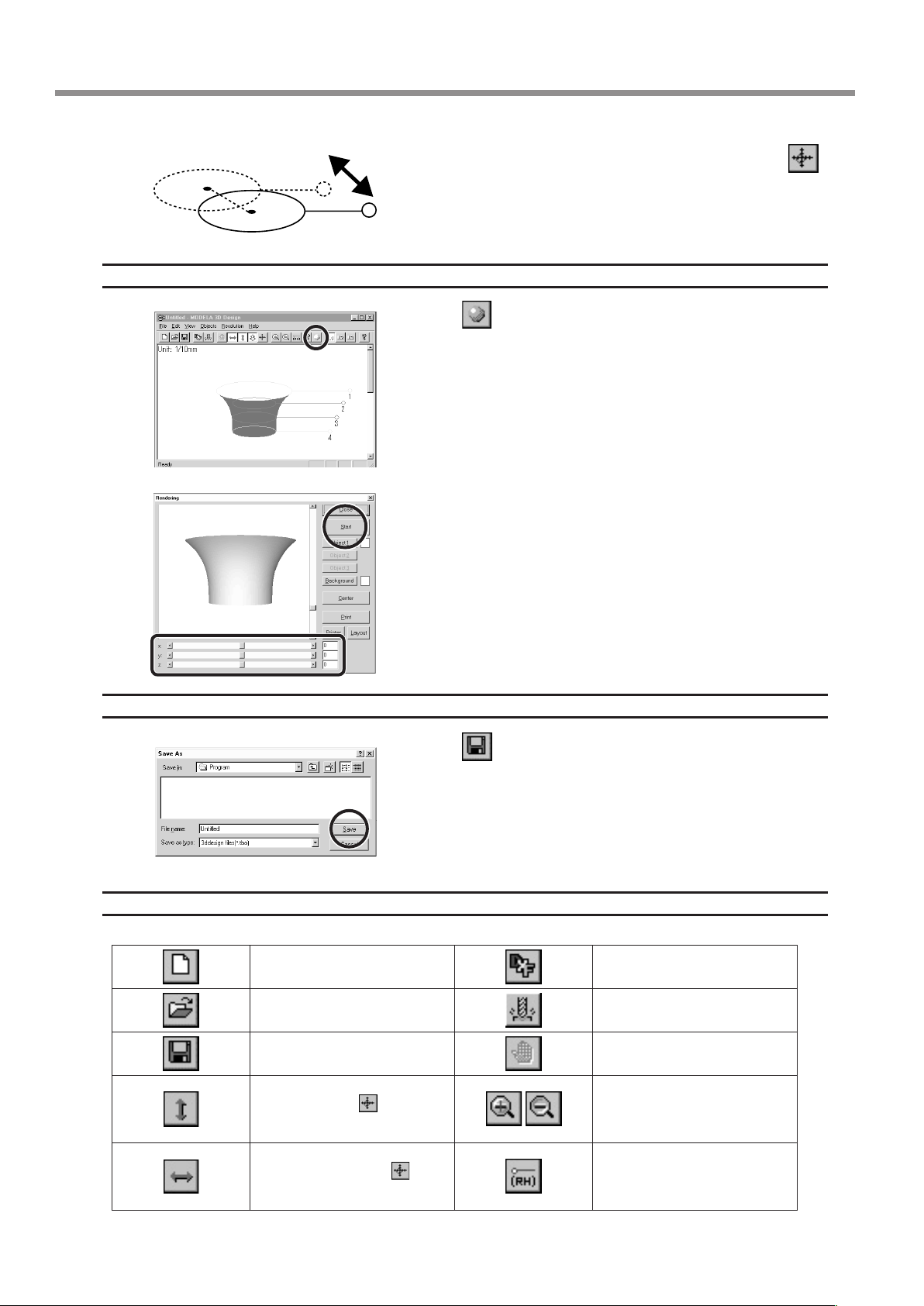
Check the shape
To change the centerpoint of the outer perimeter, click
and drag the reference line.
Save the data
Click the .
The [Rendering] dialog box appears.
Drag the scroll box for the X, Y, or Z scroll bar.
The object rotates, letting you view it from various perspectives. To color the object, click [Start].
Click the
The [Save As] dialog box appears.
.
Enter the name of the le and click [Save].
52
Description of Controls
This opens new le.
This opens an existing le. This starts MODELA Player.
This saves the le, overwriting
the previous data.
This moves a reference lines up
or down. When
the location of the centerpoint
moves up or down.
This moves a reference lines
right and left. When
lected, the location of the centerpoint moves right and left.
9 Software Guide
is selected,
is se-
This saves the data as a DXF
le.
This undoes the very last operation.
This zooms the screen in or
out.
This displays the coordinates of
the reference lines.
Page 55
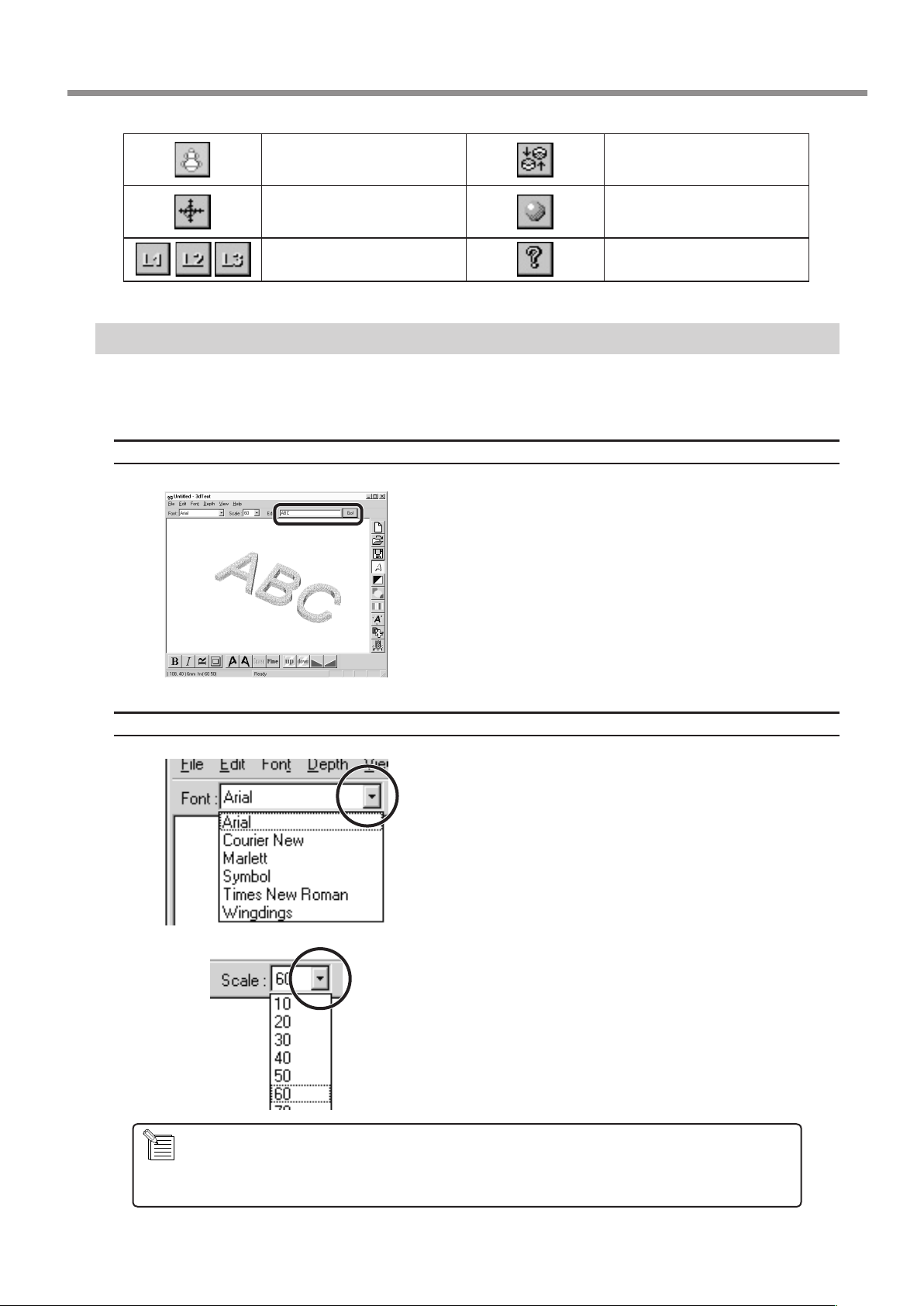
When this is selected, dragging
a reference line changes the size
of the outer perimeter.
When this is selected, dragging a
reference line moves the centerpoint of the outer perimeter.
This determines the number of
reference lines.
MODELA 3D TEXT
This adds thickness to text to create three-dimensional characters.
You can use the TrueType fonts registered in Windows as the font style for text.
Enter the Text
Click the [Edit] text box, then type in the text.
Make sure what you’ve typed in is correct, then click
[Go!].
This changes the point of view.
This adds color and shadowing
to the object's surfaces.
This displays help for 3D DESIGN.
Determine the Font and Size of the Text
Click the [Font] drop-down arrow, then click on a font
name.
- You cannot specify a font size that is not listed.
- If you want to know the size of the entire text string that you typed in, click [Show Information].
Click the [Scale] drop-down arrow, then click on a size.
9 Software Guide
53
Page 56
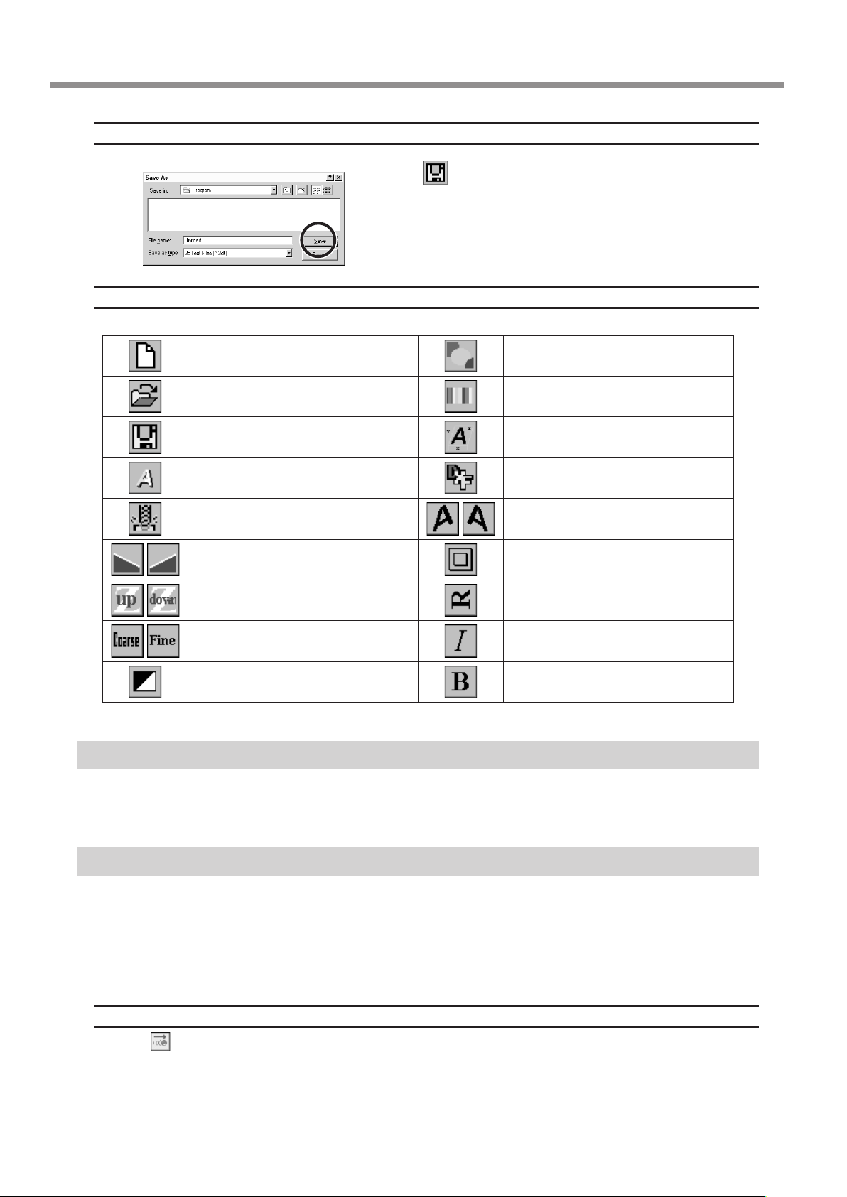
Save the data
Description of Controls
This opens new le. This lets you choose the color of the ob-
This opens an existing le. This assigns the desired color to the
This saves the le, overwriting the previous data.
This changes how the object is displayed.
This starts MODELA Player.
This slants the text in the height direction.
This changes the height of the text. This rotates each individual character 90
Click the
.
The [Save As] dialog box appears.
Enter the name of the le and click [Save].
ject from among ten available colors.
object.
This displays dimensions around the
object.
This saves the data as a DXF le.
This slants each individual character to
the left or right.
This puts a frame around the text.
degrees counterclockwise.
This determines the roughness of curved
portions of the text.
This inverts the background color. This makes the text bold.
This makes the text italic
MODELA Player
For information on how to use MODELA Player, see “6 Operation Guide [Cutting Section].”
Virtual MODELA
You can use a tool path created with MODELA Player or 3D Engrave to verify the cutting process and results on-screen before
you perform actual cutting.
You can start this program directly with commands from MODELA Player or 3D Engrave. For more information, see "6 Operation Guide [Cutting Section] - Sending Cutting Data" or "9 Software Guide - 3D Engrave."
With Virtual MODELA, you can display the cutting process and results in a wide variety of ways.
Animating the Screen During Simulation
54
Click the . When this button is o, only the shape after simulation is displayed.
9 Software Guide
Page 57
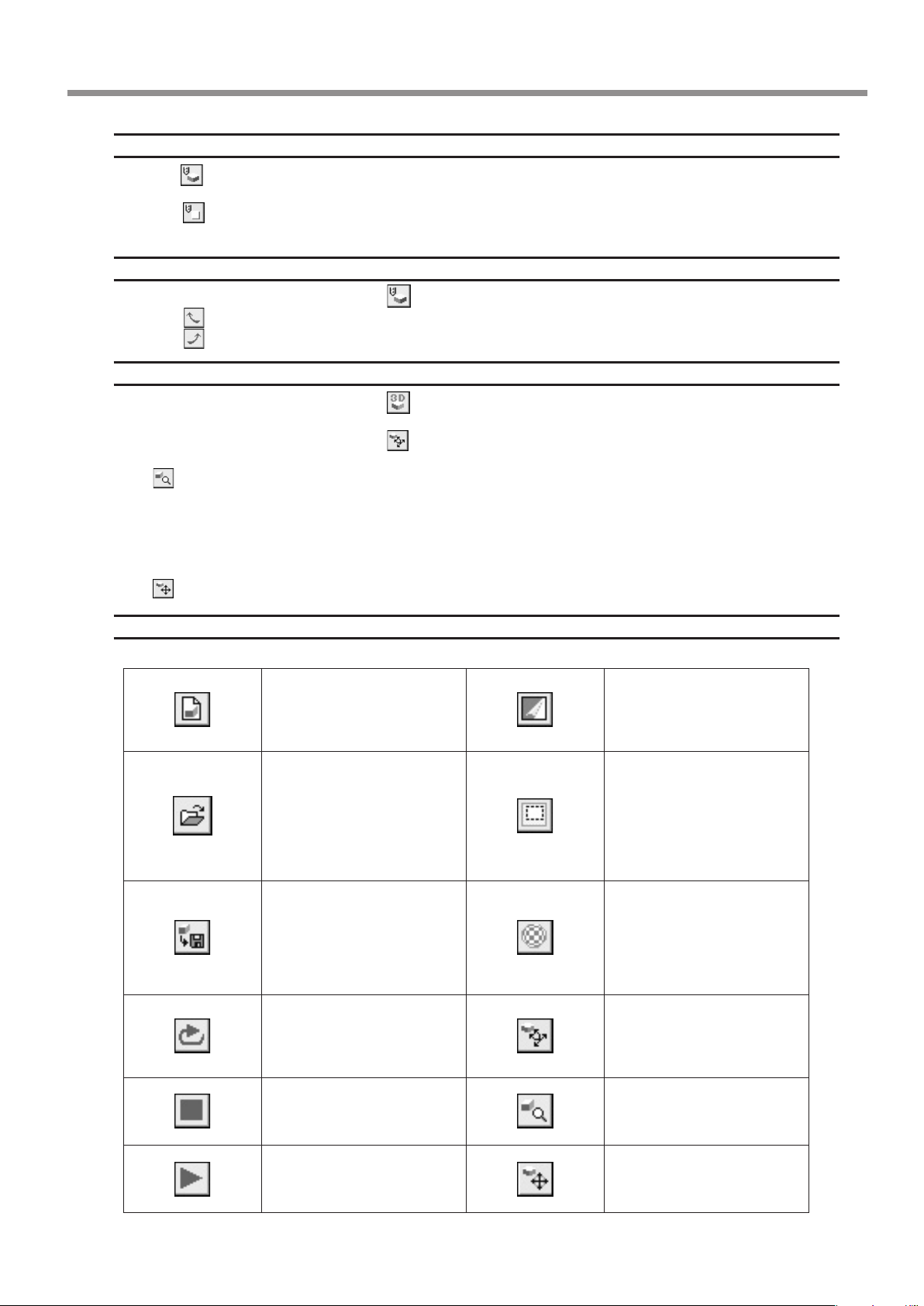
Switching the Screen Between Flat and Three-dimensional Views During Simulation
• Clicking switches from a at view to a three-dimensional view. When this button is selected, the view is three-dimensional
during and after simulation.
• Clicking
of the workpiece as seen from above during and after simulation.
switches from a three-dimensional view to a at view. When this button is selected, the display shows a view
Changing the Perspective at the Simulation Screen (Only During 3D View)
You can use the following buttons only when has been clicked to display a 3D view.
• Clicking
• Clicking
rotates the object counter-clockwise around the Z axis, in steps of 90 degrees.
rotates the object clockwise around the Z axis, in steps of 90 degrees.
Checking the Shape After Simulation
You can use the following buttons only when has been clicked.
• Rotating
You can use the following buttons only when has been clicked.
• Zooming in or out
Click , then drag on the screen.
Zoom in
Drag toward the top of the screen.
Zoom out
Drag toward the bottom of the screen.
• Moving the Location
Click , then drag on the screen.
Description of Controls
This creates a new, uncut workpiece.
This opens an existing cuttingconguration le.
This saves the shape of the present workpiece in a le.
This performs the cutting simulation over again, using the presently imported tool path. Use
this when you want to check the
movement of the tool again.
This quits the simulation. This zooms the view of an object
This starts cutting.
If cutting was previously interrupted, it resumes cutting.
This switches between adding
and not adding color to the
surface of the workpiece.
To specify a color, click [Options]
- [Surface Color].
This restricts the 3D view
range.
It also determines the printing area when performing 2D
simulation.
Restricting the range makes 3D
view faster than when displaying the entire workpiece.
This pastes and image on the
surface of the workpiece.
By pasting an image of wood or
metal, you can make the workpiece look more realistic.
To select the image to paste, click
[Options] - [Texture Setup].
This rotates the object, changing
the perspective.
This is available only during
3D view.
in or out.
This is available only during
3D view.
This changes an object's displayed location on the screen.
This is available only during
3D view.
9 Software Guide
55
Page 58
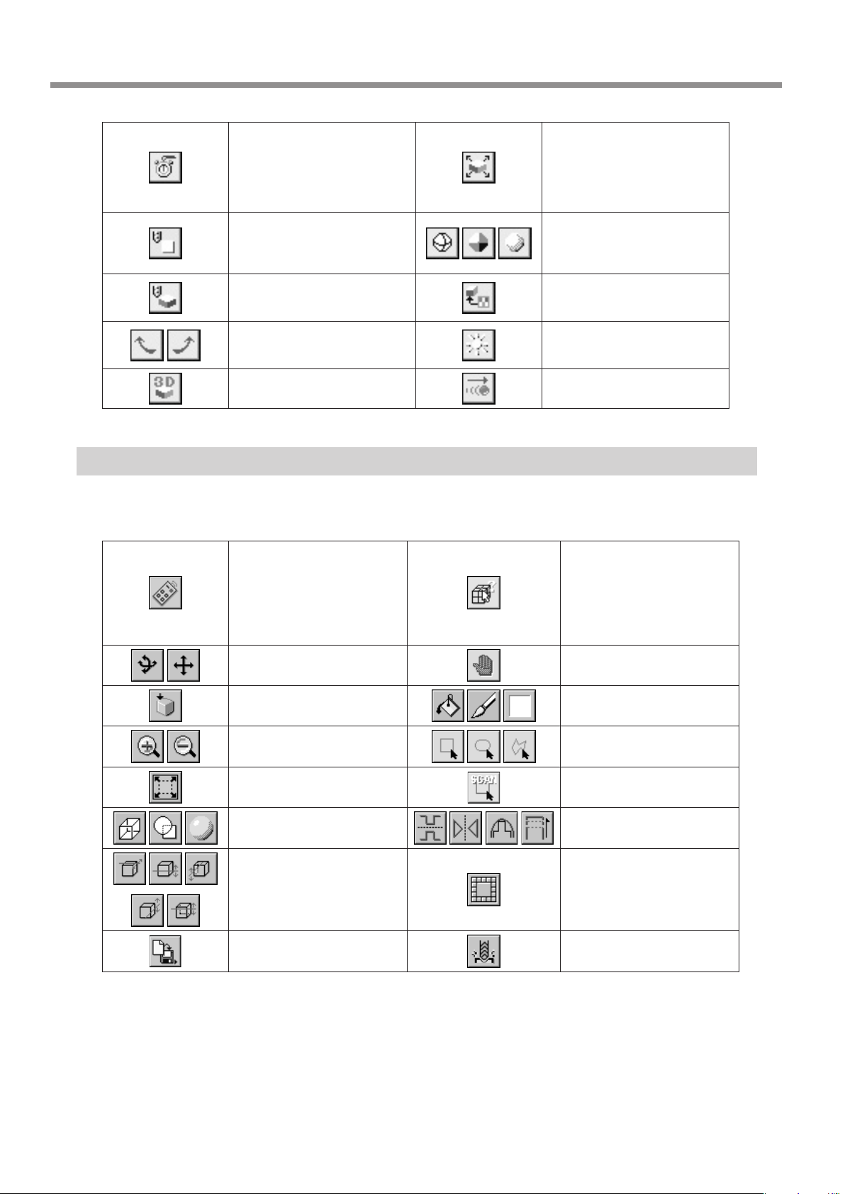
This displays a prediction of how
much time cutting will take. The
time is a general estimate.
In addition to the time, you can
also verify the tool movement
distance and movement range.
This displays the simulation
screen as a at (two-dimensional) view.
This displays the simulation
screen as a solid (three-dimensional) view.
These change the perspective
when displaying a simulation
three-dimensionally.
This is for checking the shape
after cutting simulation.
Dr.PICZA
For information on how to use Dr. PICZA, see “7 Operation Guide [Scanning Section].”
This section describes the controls for Dr. PICZA.
This unhides and hides the
controller window. At the controller window, you can make
the settings for the various
scanning parameters.
These choose how an object
moves when dragged.
This enlarges or reduces what
is displayed to ll the drawing
size.
This selects how the object
is displayed when on the 3D
screen when not performing
any operation.
This selects the image to paste
on the surface of the workpiece.
This changes the direction and
brightness of incident light,
thereby changing the shading.
This displays the movement of
the tool with animation.
These display the coordinates
of the point chosen with the
mouse pointer.
Clicking a start point and
an end point shows you the
distance between the two
points.
This undoes the very last operation.
This displays the top surface
of an object.
These zoom the view of an
object in or out.
This displays the object, lling
the view area.
These choose how an object
is drawn.
These adjust the slant of an
object.
This saves data in various le
formats.
These color a surface of the
object.
These specify the edit area for
three-dimensional data.
This specifies the range to
rescan.
These edit three-dimensional
data.
This deletes data in the selected range.
This starts MODELA Player.
56
9 Software Guide
Page 59
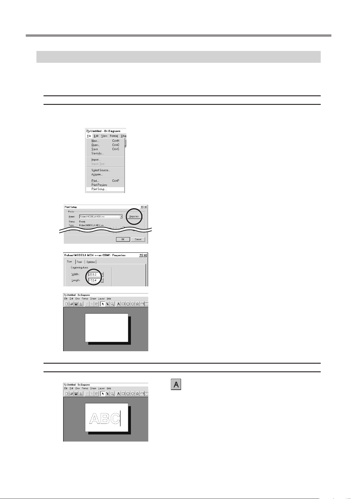
Dr. Engrave
This is used to design plates and send the engraving data to MODELA.
You can make large numbers of plates with the same design (such as nameplates and rating plates) with high eciency.
Set the Engraving Area
The following explanation is for Windows 95/98/Me. If you're using Windows NT4.0/2000/XP, then refer to the explanation
in "9. Software Guide - Driver for Windows NT 4.0/2000/XP - Enter the Cutting Area."
From the [File] menu, click [Print Setup...].
The [Print Setup] dialog box appears.
Make sure [Roland MODELA MDX-20] is specied as the
printer, then click [Properties].
The [Roland MODELA MDX-20] dialog box appears.
Enter the size of the plate, then click [OK].
Next, click [OK] to close the [Printer Setup] dialog box.
The white portion of the screen is the engraving area. Lay out shapes
and text inside the area.
Type in the Text
Click
type in text.
While in this state, type in the text with the keyboard.
, then click at the location where you want to
9 Software Guide
57
Page 60

Draw a Shape
Click on the shape-drawing controls to draw the shapes.
Change the Size and Location of a Shape or Text
Click , then click the shape or text.
Solid square (
) and triangle (
) pointers appear around the shape or text. To change the size, drag the pointers.
<Changing the Size>
You can freely change the
size of the object by dragging. To retain the object’s
vertical/horizontal aspect
when you change its size,
hold down the [Shift] key
while dragging.
<Rotating and Slanting>
Clicking again makes the pointers change to circles () and diamonds ( ).
Drag to rotate the shape.
Drag to change the vertical size.
Drag to change the horizontal size.
Drag the “ ” to slant the shape.
58
<Moving the Location>
To change the location, drag
between the pointers.
9 Software Guide
Page 61
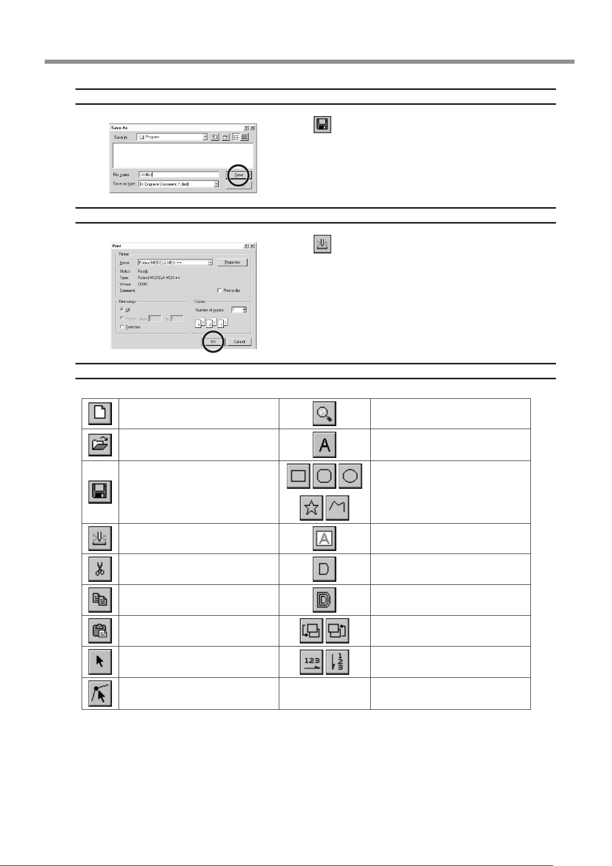
Save the Data
Start Engraving
Description of Controls
This opens new le. This zooms the screen in or out.
Click the
.
The [Save As] dialog box appears.
Enter the name of the le and click [Save].
Click the
The [Save As] dialog box appears.
.
To start engraving with MODELA, click [OK].
This opens an existing le. This types in the text
This saves the file, overwriting the
previous data.
This sends engraving data to MODELA.
This deletes the selected object and
copies it to the clipboard.
This copies the selected object to the
clipboard.
This copies the clipboard data to the
screen.
This selects a shape or text.
This is used to reposition the vertices of
a polygon, changing its shape.
This draws the shapes
This makes an entry frame for text.
This changes the chosen text string to
line characters.
This performs at-drag machining for
the interior of a shape or text.
These change the context of an object.
These set the direction of the text
string.
9 Software Guide
59
Page 62

3D Engrave
This adds thickness to a at (two-dimensional) graphic to create a relief (raised engraving).
You can also add thickness to images such as illustrations.
3D Engrave is a program for creating reliefs (raised engravings) and engravings on curved surfaces.
This section describes the steps for cutting a relief.
For detailed descriptions of the creation steps and more information about creating data for engraving.
Select the Output Device
See "5 Installing the Software - Program Settings" and choose the model you're using.
Decide on the Size of the Relief
From the [Relief] menu, click [Relief Size].
The [Relief Size] dialog box appears.
Enter the size of the relief and the resolution (the degree
of detail of the relief), then click [OK].
The screen at right appears. The white area of the screen is the where
you design the relief.
The screen displayed at this time is called the "2D screen." It's the
screen for typing in text and creating shapes.
60
Creating Shapes and Entering Text
To create a shape, click one of the shape-drawing buttons
and drag.
To enter text, click the text-entry button, then click the
location where you want to insert text. While in this state,
type in the text with the keyboard.
To change the size of a shape or text, refer to "Dr. Engrave - Changing
the Size and Location of Shapes and Text."
9 Software Guide
Page 63

Create a Raised Engraving (Relief)
Add thickness to shapes and text to create a relief.
Click the shape or text string you want for adding thickness to select it.
Click the .
The [Relief Size] dialog box appears.
The dialog box may dier depending on the type of object you selected. The following screen shows the
dialog box that appears when creating a relief of shapes or text.
Make the settings for the required items for creating the relief, then click [OK].
Enter the height of the bottom of the relief.
Enter the thickness of the relief.
These choose the conguration for
pushing the object up (or down).
These choose how to stack the relief.
This is for entering the angle of the base side
when
This is for entering the direction of the relief
ridge. You can enter a value when a button
other that
When this is selected, the relief of
the chosen object is smoothed.
These choose whether to push down or stack
using the value entered for the relief height.
has been selected.
has been selected.
The display changes automatically to the screen at right, and a threedimensional view of the shape of the relief appears.
This is called the "3D screen," and it displays the shape of the relief
and the tool path. You cannot edit shapes or text.
9 Software Guide
61
Page 64
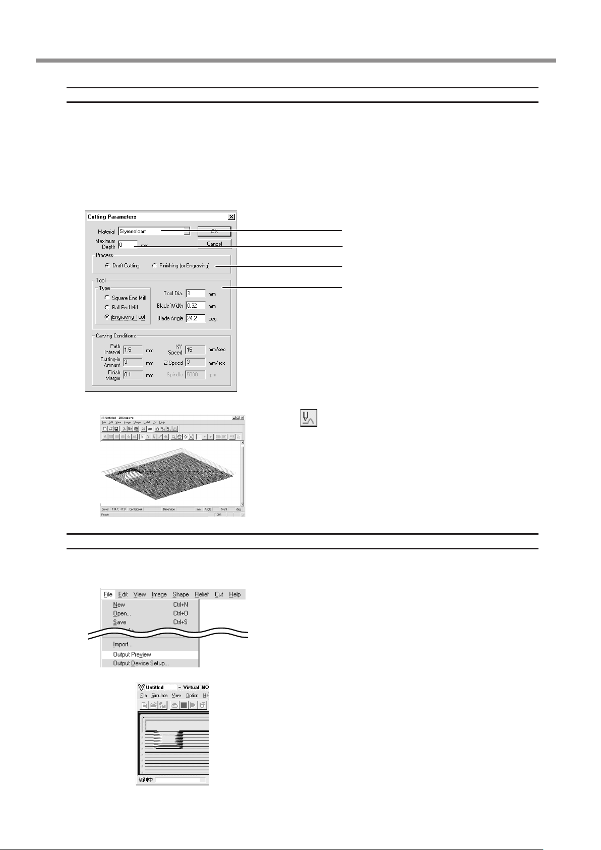
Creating a Tool Path
A tool path is the path followed by the tool's tip. The tool path is generated from the cutting parameters that are presently
set.
Before you create the tool path, make the settings for the cutting parameters. At the cutting parameters, make the settings
for the composition of the workpiece, the type of tool, and the cutting process.
From the [Cut] menu, click [Cutting Parameters].
The [Cutting Parameters] dialog box appears.
Make the settings for the necessary items for cutting, then click [OK].
This chooses the composition of the workpiece.
This sets the depth for cutting.
This chooses the cutting process.
Make the settings for the tool specications.
Click the . When the tool path is created, it appears in
pink on the 3D screen.
Checking the Cutting Results
If Virtual MODELA is installed and set up, then before you perform actual cutting you can check the shape that will be produced after cutting on the screen.
From the [File] menu, click [Output Preview].
Virtual MODELA starts.
The cutting data from 3D Engrave is imported into Virtual MODELA.
An animated display of tool movement appears, and the shape after
cutting is gradually produced.
62
* For more information on how to operate Virtual MODELA, see the
help for Virtual MODELA.
9 Software Guide
Page 65
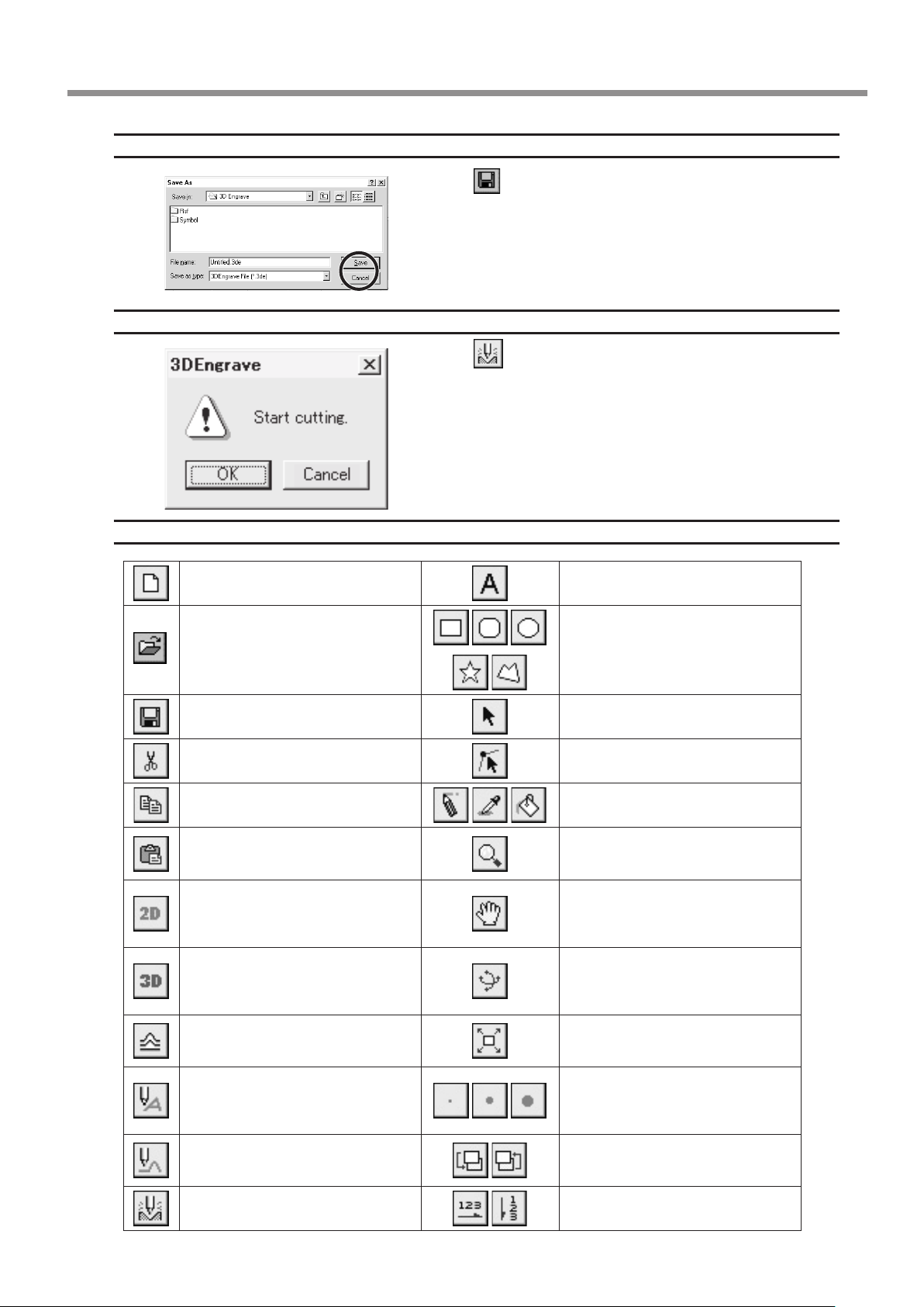
Save the Data
Start Engraving
Description of Controls
This opens new le. This types in the text
This opens an existing le.
Click the
.
The [Save As] dialog box appears.
Enter the name of the le and click [Save].
Click the
.
When the screen at right appears, click [OK].
Cutting with MODELA starts.
This draws the shapes
This saves the file, overwriting the
previous data.
This deletes the selected object and
copies it to the clipboard.
This copies the selected object to the
clipboard.
This copies the clipboard data to the
screen.
This switches to a at (two-dimensional) shape editing screen.
This switches to a solid (three-dimensional) display screen. Display this
screen when you want to check a tool
path or the shape of a relief.
This adds thickness to shapes, text,
images or other at objects to create
a relief (raised engraving).
This creates a tool path for engraving
for the selected shapes and text. The
tool path for engraving appears on the
3D screen as a red line.
This creates a tool path for relief cutting. The tool path for cutting appears
on the 3D screen as a pink line.
This outputs the tool path to the MODELA and starts cutting.
This selects a shape or text.
This is used to reposition the vertices of
a polygon, changing its shape.
These are used to retouch imported
images.
This zooms the screen in or out. The
mouse operations for the 2D screen
and the 3D screen are dierent.
This changes the display location of the
object. This moves the screen display to
show areas outside the window which
are not visible.
This changes the perspective of the
relief when you drag the screen. This is
available only during 3D screen.
This command expands or reduces
the size of the object shown to ll the
screen.
These select the pen width for retouching an image.
These change the context of an object.
These set the direction of the text
string.
9 Software Guide
63
Page 66
For China
产品中有毒有害物质或元素的名称及含量
有毒有害物质或元素
部件名称
印刷电路板 × ○ × ○ ○ ○
头部 × ○ ○ ○ ○ ○
壳体、底架 × ○ ○ ○ ○ ○
电源 × ○ × ○ ○ ○
其他(电缆、附件等) × ○ ○ ○ ○ ○
○:表示该有毒有害物质在该部件所有均质材料中的含量均在 GB/T26572-2011 标准规定的限量要求以下。
×:表示该有毒有害物质至少在该部件的某一均质材料中的含量超出 GB/T26572-2011 标准规定的限量要求。
环
保使用期限
铅(Pb) 汞(Hg) 镉(Cd)
此标志适用于在中国国内销售的电子信息产品,表示环保使用期限的年数。
所谓环保使用期限是指在自制造日起的规定期限内,产品中所含的有害物质
不致引起环境污染,不会对人身、财产造成严重的不良影响。
环保使用期限仅在遵照产品使用说明书,正确使用产品的条件下才有效。
不当的使用,将会导致有害物质泄漏的危险。
六价铬
(Cr(Ⅵ))
多溴联苯
(PBB)
多溴二苯醚
(PBDE)
For EU Countries
This product must be disposed of
separately at your local waste recycling
center. Do not dispose of in household
waste bin.
Bitte führen Sie dieses Produkt separat
Ihrer örtlichen Entsorgungsstelle zu.
Bitte nicht mit dem normalen Hausmüll
entsorgen.
Ne jetez pas le produit avec vos
ordures ménagères. Portez-le dans un
centre recyclage des déchets.
Questo prodotto deve essere smaltito
negli appositi contenitori per la raccolta
differenziata, non buttare nel cestino
dei rifiuti casalinghi.
Este producto debe devolverse al
centro de reciclaje más cercano a su
domicilio para su correcta eliminación.
No lo tire a la basura.
Lever dit product in bij een lokaal
afvalverzamelpunt. NIET met normaal
huishoudelijk afval afvoeren.
Dette Produkt skal smides særskilt
væk på den lokale affalds- og
genbrugsstation. Må ikke smides ud
sammen med almindeligt
husholdningsaffald.
Tätä tuotetta ei saa hävittää
normaalien talousjätteiden mukana,
vaan se on toimitettava
ongelmajätteiden keräilypisteeseen
hävitettäväksi.
Produkten måste kasseras separat på
din lokala återvinningscentral. Släng
inte produkten tillsammans med
hushållssoporna.
Μην πετάξετε το αντικείμενο αυτό στο
καλάθι των απορριμμάτων. Αφαιρέστε
τις μπαταρίες και προσκομίστε το στο
τοπικό κέντρο ανακύκλωσης.
64
Deite fora separadamente este produto
no seu centro de reciclagem local. Não
o deite fora no seu caixote do lixo.
Page 67

10 What to Do If...
The MODELA doesn't operate
Is the STANDBY key on?
Press the STANDBY key.
Has operation not been paused by pressing the VIEW key (lighting up the VIEW LED)?
Press the VIEW key to cancel the View state.
Are the cable connected correctly?
Check the output ports for MODELA and the computer and make sure they are connected correctly.
Is the cable for the connection with the computer suited to the MODELA and the computer?
- For the cable, use a optionally available serial cable (such as XY-RS-34). A straight serial cable such as is commonly used
to connect a modem cannot be used.
Are the settings for the computer and the software correct?
Check the following and make the correct settings.
Data output port : Port connected to any one of COM1 through COM4
Communication parameters : Bit rate of 9,600, no parity, one data bit, stop bit 8, and hardware handshaking
Selected output device : MDX-15 or MDX-20
Pressing the STANDBY key does not switch off the power
Unplug the AC adapter from the unit.
The MODELING MODE LED or SCANNING LED Flashes Rapidly (Ten Times Per Second)
Was the power switched on in the correct sequence?
First turn on the computer, then turn on MODELA.
This indicates a communications error.
Switch o the power, then check the cable connections and the port setting for the driver.
Was the computer restarted?
When the computer has been restarted, switch the power to the MODELA o, wait a few seconds, then switch it back on.
All LEDs Flash Slowly (every 0.5 sec.)
Has the cord come loose from the spindle unit or the sensor unit?
Switch o the power and reconnect the cords to the jacks.
Errors During Cutting
Speed drops during cutting
When cutting a workpiece of uneven hardness, such as wood, the MODELA may slow down automatically (to a minimum speed
of 0.1 mm (0.00394 in.) /sec.). Once the MODELA has gone beyond the hard area, cutting continues at normal speed.
The STANDBY LED is ashing slowly (every 0.5 sec.)
The workpiece cannot be cut, even when the speed is reduced. Switch the power o and back on.
Make sure the cutting tool being used is appropriate for the hardness of the workpiece in use. Modify the software settings
to cut the workpiece a little at a time.
Tool movement is different than the data
If an attempt is made to cut more deeply than the range of movement for the MODELA allows, the tool automatically rises
10 What to Do If...
65
Page 68

to the uppermost point.
Check to make sure that depth settings in the cutting data are not too deep, and that the tool extending from the spindle
unit is not too short.
Correct cutting is impossible
Are the cutting tool, spindle, and workpiece all installed and loaded securely?
Retighten the setting screw for the tool and the mounting screws for the spindle.
Unusual noise is heard from the spindle
The spindle unit is a consumable part. Replace with a new spindle unit after 700 hours of use.
The spindle motor does not run
The spindle motor is a consumable part. Replace with a new spindle motor after 700 hours of use.
The VIEW LED is ashing slowly (every 1 sec.)
Is the front cover detached?
Install the front cover.
When a sensor unit is installed, the VIEW LED does not ash.
The SCANNING LEDs repeatedly ashes twice
Something touched the sensor during initial operation immediately after switching on the power, or a
hardware error occurred.
If there is an obstruction, then switch o the power, remove the obstruction, and switch the power back on.
If there was a hardware error, then switch the power o and back on and repeat the same operation.
If the same error display occurs, consult your authorized Roland dealer or service center.
Unexpected Program Operation
I can't open a le.
Does the program you’re using support the format of the le you’re trying to open?
Check the program and the le format, and make sure the combination is supported.
There is not enough memory available for processing.
Close all other applications, or restart Computer.
If the le cannot be opened even after restarting the program, there may not be enough free space left on the hard disk.
If this is the case, free up space on the hard disk by deleting unneeded les or moving them to another disk.
If the messages about insucient memory still appears after doing this, it is recommended that you increase the amount
of memory in your computer.
The included software doesn't function.
Does the computer you're using provide the correct operating environment for the included software?
Refer to the [Read Me] and check the operating environment, and use a computer that meets the operating-environment
requirements.
Was the software installed using the setup program?
Be sure to use the setup program when installing the software.
The setup program puts the les for each software package in the necessary locations to enable the software to be used
under Computer.
If an Error Message Appears
Refer to the help for the program you’re using.
66
10 What to Do If...
Page 69

11 Items That May Not Be Copied
Unauthorized reproduction of a copyrighted item for any purpose other than personal use may be a violation of copyright.
Roland DG Corp. will not be responsible for any violation of third-party copyright by any article made through use of this
product.
11 Items That May Not Be Copied
67
Page 70
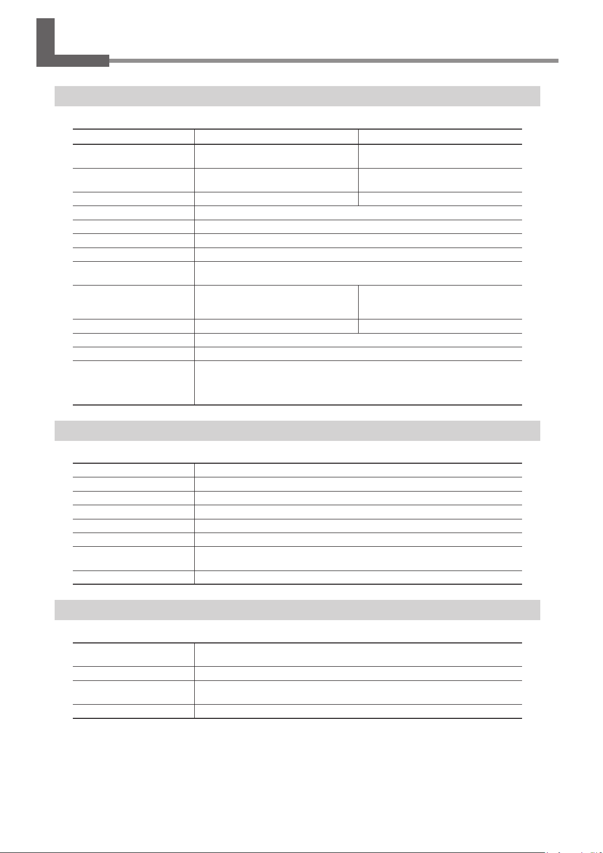
12 Specications
Main Unit Specications
XY table size
Max. operation area
Max. table load weight
Interface
Control keys
LED
Power consumption
Acoustic noise level
External dimensions
Weight (unit only)
Operation temperature
Operation humidity
Accessories
220 mm (X) x 160 mm (Y) ( 8-5/8 in. x
6-1/4 in. )
203.2 mm (X) x 152.4 mm (Y) x 60.5 mm
(Z) (8 in. (X) x 6 in. (Y) x 2-3/8 in. (Z))
1000 g (2.2 lb.) 500 g (1.1 lb.)
Serial (RS-232C)
STANDBY key, VIEW key, TOOL-UP key, TOOL-DOWN key,
SCANNING MODE LED, MODELING MODE LED, VIEW LED
Exclusive AC adapter (DC+19V 2.1 A)
Standby mode : under 35 dB (A)
Operation mode (not cutting) : under 70 dB (A) (According to ISO 7779)
476.8 mm (W ) x 381.6 mm (D) x 305 mm
(H) (18-13/16 in. (W) x 15-1/16 in. (D) x
12-1/16 in. (H))
13.7 kg (30.2 lb.) 9.6 kg (21.2 lb.)
5 to 40°C (41 to 104°F)
35 to 80 % (no condensation)
AC adapter: 1, power code: 1, Roland Software Package CD-ROM: 1, spindle unit: 1,
sensor unit: 1, cap screw M4x15: 4, tool:1, set screw M3x3: 2, double-sided tape: 1,
front cover: 1, hexagonal wrench (size : 3 mm) :1, hexagonal wrench (size : 1.5 mm):
1 positioning pins: 3, clay: 1, MDX-20/15 user's manual: 1
MDX-20 MDX-15
170 mm (X) x 110 mm (Y) ( 6-11/16 in.
x 4-5/16 in. )
152.4 mm (X) x 101.6 mm (Y) x 60.5 mm
(Z) (6 in. (X) x 4 in. (Y) x 2-3/8 in. (Z))
426 mm (W) x 280 mm (D) x 305 mm
(H) (16-13/16 in. (W) x 11-1/16 in. (D) x
12-1/16 in. (H))
Modeling Functions
Tool chuck
Spindle motor
Software resolution
Mechanical resolution
Revolution speed
Feed rate
Acceptable material
Acceptable tool
6 mm or 1/8 in. tool chuck included
10W (DC motor)
0.025 mm/step (0.000984 in./step)
0.00625 mm/step (0.000246 in./step)
6500 rpm
0.1 to 15 mm/sec. (0.00393 to 9/16 in./sec.)
Wood, Plaster, Resin (modeling wax, styrenform), Chemical wood, Aluminum (A5052
according to JIS), Brass
Endmill, Drill
Scanning Functions
Sensor
Scanning method
Scanning pitch
(Dr. PICZA)
Scanning speed
Roland Active Piezo Sensor (R.A.P.S.)
Probe length 60 mm (2-5/16 in.), tip bulb diameter 0.08 mm (0.00315 in.)
Contacting, mesh-point height-sensing
X/Y-axis directions -- 0.05 to 5.00 mm (0.002 to 0.20 in.) (settable in steps of 0.05 mm
(0.002 in.)) Z-axis direction -- 0.025 mm (0.000984 in.)
4 to 15 mm/sec. (1/8 to 9/16 in./sec.)
68
12 Specications
Page 71
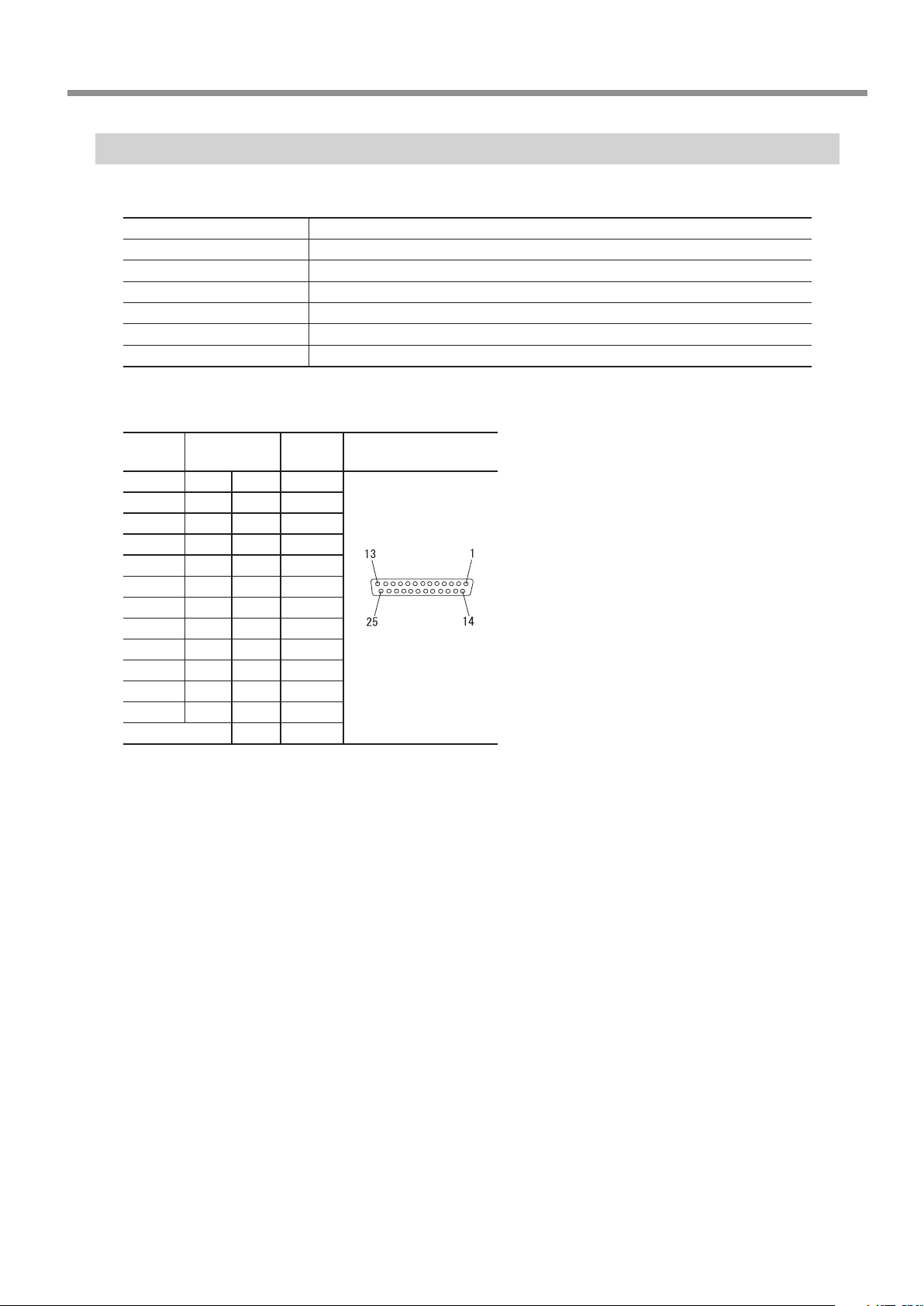
Interface Specication
[Serial]
Standard
Transmission method
Transmission speed
Parity Check
Data Bits
Stop Bits
Handshake
Serial connector (RS-232C)
Signal
number
NC 25 13 NC
NC 24 12 NC
NC 23 11 NC
NC 22 10 NC
NC 21 9 NC
DTR 20 8 NC
NC 19 7 SG
NC 18 6 DSR
NC 17 5 CTS
NC 16 4 RTS
NC 15 3 RXD
NC 14 2 TXD
Terminal
number
1 FG
RS-232C specications
Asynchronous, duplex data transmission
9600 bps
None
8 bits
1 bits
Hardware
Signal
number
Pin connection
12 Specications
69
Page 72

Please read this Agreement before unpacking the media.
Software license agreement
Roland DG Corporation (hereinafter referred to as the “Company”) shall grant you a non-transferable, nonexclusive right to use the
Software supplied with this Agreement, on the condition that you agree to the following provisions.
If you agree to the following provisions, you should unpack the media on which the Software is recorded, or simply click the button
or other indicator that you agree to the following provisions. By doing so, this Agreement shall be concluded.
If you do not agree with the following provisions, do not unpack the media. Or, you can click the button or other indicator that you do
not agree to the following provisions of this Agreement. In this case, a license is not granted and you cannot use the Software.
1. Denition
The “Software” includes the software program and related les supplied with this Agreement and the related software programs
and les distributed through the Internet and other services.
2. Ownership
All the ownership, copyright and other intellectual property rights of the Software, trademark, and related documents shall belong
to the Company.
3. Terms and conditions
(1) You are authorized to use the Software on one computer.
(2) You are allowed to create a backup copy of the Software.
The right to keep the Software and the backup copy of the Software continues to belong to the Company, but the right to the
media on which the backup copy of the Software is recorded does not belong to the Company.
4. Forbidden items
(1) This copy of the Software, or a backup copy of the Software, must not be used on multiple computers at the same time, on a
network, the Internet, or on other computers through any other means of distribution.
(2) The Software shall not be reverse engineered, decompiled or reverse assembled.
(3) The rights to the Software cannot be transferred, assigned, lent, loaned or licensed to a third party in any case, regardless of
whether this Agreement has been terminated or cancelled.
5. Termination
(1) The Company can cancel this Agreement and require you to discontinue use of the Software if you breach any provision of this
Agreement or if you infringe on the ownership, copyright, or other intellectual property rights of the Company.
(2) This Agreement shall be automatically terminated when you stop using the Software.
(3) If this Agreement is terminated or cancelled, you must return your copy of the Software to the Company, or discard it as soon
as practicable, at your own expense.
6. Guarantee
(1) The Company shall not guarantee that the quality or functionality of the Software will satisfy any purpose that you may have
in mind.
(2) The Company shall not accept any responsibility for the results obtained from using the Software.
(3) The Company shall not accept any responsibility for any loss which might be caused as a result of your exercising the rights
granted under this Agreement.
(4) The specications for the Software are subject to change without prior notice.
7. Governing Law
This Agreement shall be governed by the laws of Japan.
R7-120615
 Loading...