

Page 1

MC-307 JAN, 2000
TABLE OF CONTENTS 目次
SPECIFICATIONS . . . . . . . . . . . . . . . . . . .
LOCATION OF CONTROLS . . . . . . . . . . .
LOCATION OF CONTROLS PARTS LIST
EXPLODED VIEW . . . . . . . . . . . . . . . . . . .
EXPLODED VIEW PARTS LIST . . . . . . . .
PARTS LIST . . . . . . . . . . . . . . . . . . . . . . . .
IDENTIFYING THE VERSION NUMBER
USER DATA SAVE AND LOAD . . . . . . . . .
FACTORY RESET . . . . . . . . . . . . . . . . . . .
HOW TO VERSION UP THE FLASH ROM
TEST MODE. . . . . . . . . . . . . . . . . . . . . . . .
BLOCK DIAGRAM . . . . . . . . . . . . . . . . . . .
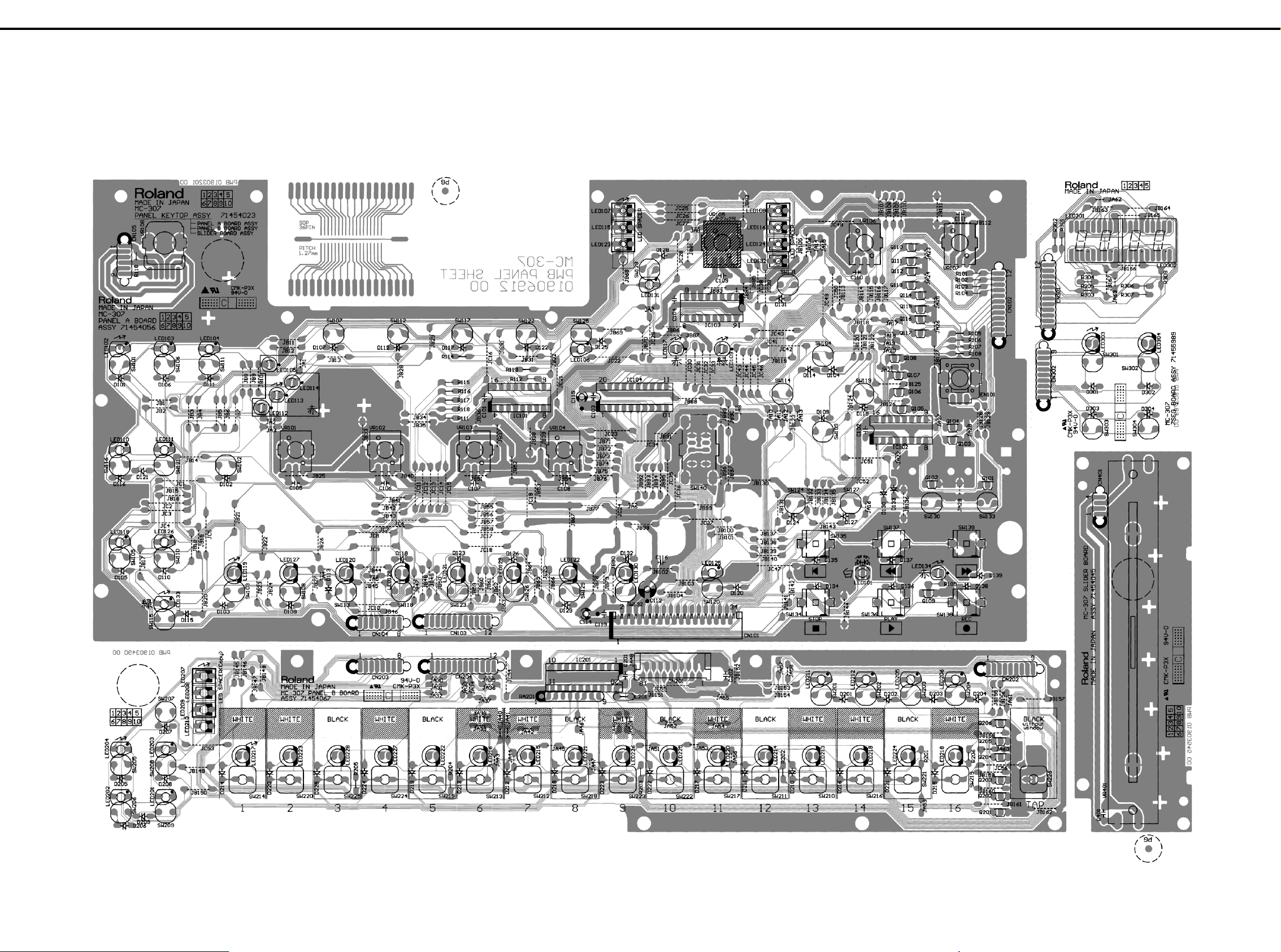
CIRCUIT BOARD . . . . . . . . . . . . . . . . . . . .
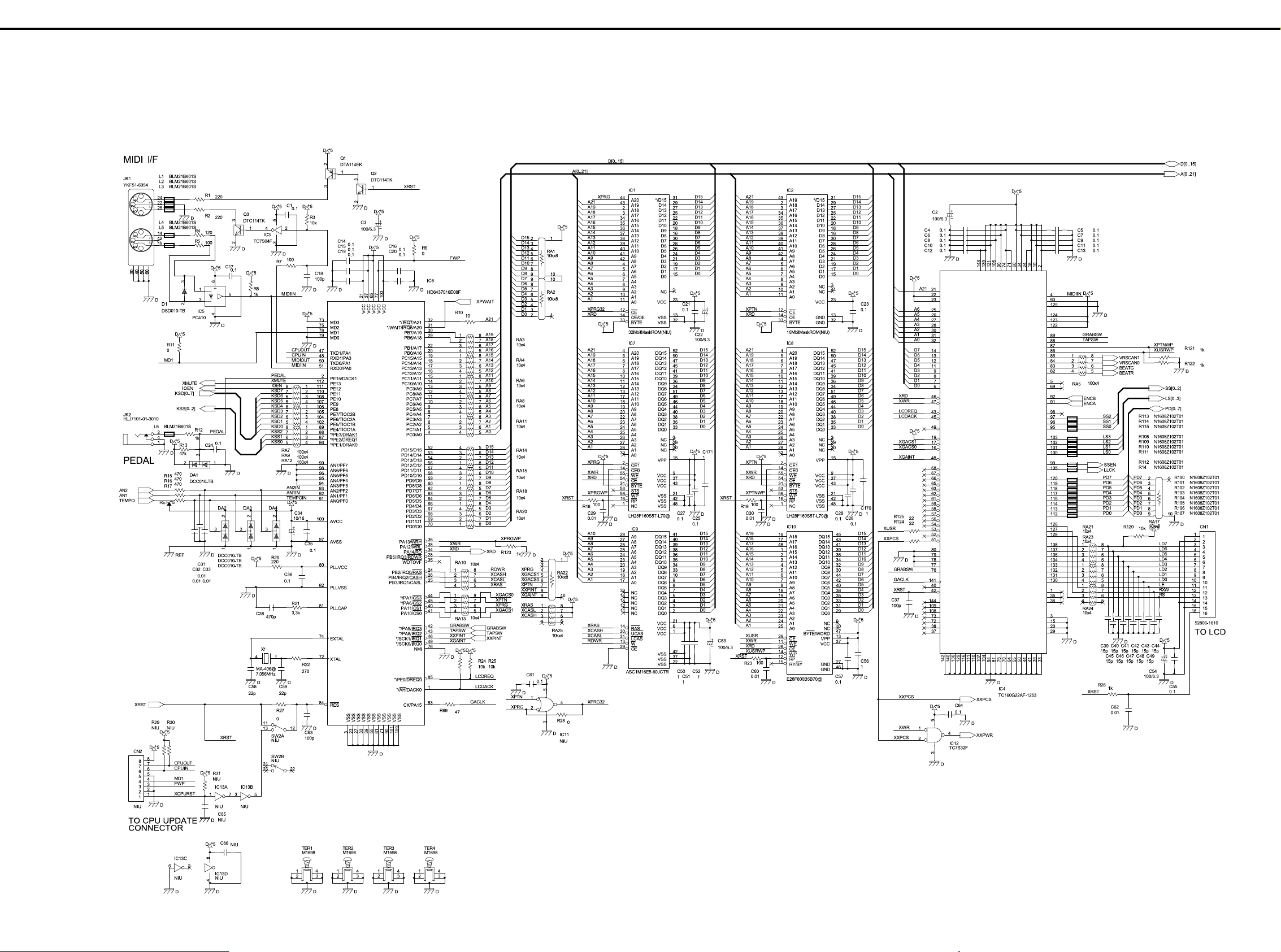
CIRCUIT DIAGRAM . . . . . . . . . . . . . . . . . .
ERROR MESSAGES . . . . . . . . . . . . . . . . .
目次 Page
目次目次
スペック/主な仕様
パネル配置図
. . .
パネル配置図パーツリスト
分解図
分解図パーツリスト
パーツリスト
. . .
バージョンナンバーの確認方法
データのセーブとロード
ファクトリーリセットの方法
. . .
フラッシュ ROM バージョンアップの方法
テストモード
ブロック図・配線図
基板図
回路図
エラー・メッセージ
. . . . . . . . . . . . . . . . . . . . . . 1
. . . . . . . . . . . . . . . . . . . . . . . . . . . . 2
. . . . . . . . . . . . . . . . . 2
. . . . . . . . . . . . . . . . . . . . . . . . . . . . . . . . . 3
. . . . . . . . . . . . . . . . . . . . . . 3
. . . . . . . . . . . . . . . . . . . . . . . . . . 4-6
. . . . . . . . . . . . . 7
. . . . . . . . . . . . . . . . . . . 7
. . . . . . . . . . . . . . . 7
. . . . 8-9
. . . . . . . . . . . . . . . . . . . . . . . . 10-12
. . . . . . . . . . . . . . . . . . . . . 13
. . . . . . . . . . . . . . . . . . . . . . . . . . . . . 14-16
. . . . . . . . . . . . . . . . . . . . . . . . . . . . . 17-21
. . . . . . . . . . . . . . . . . . . . . 22
MAIN SPECIFICATIONS
MC-307: Groovebox
SOUND GENERATOR
SECTION
Maximum Polyphony: 64 voices
Parts: 24 (Main: 8, RPS: 16)
Patches
Preset: 800
User: 256
Rhythm Set
Preset: 40
User: 20
Effects Type
Reverb: 6
Delay: 2
Multi-Effects (M-FX): 25
SEQUENCER SECTION
Parts: 8 + MUTE CTRL
Resolution:
96 ticks per quarter note
Tempo: 20.0-240.0 (Maximum)
Maximum Note Storage:
95,000 notes
Patterns
Preset: 240
RPS: 470
User: 200
Songs: 50
Recording Mode:
Realtime, TR-REC
Quantize Type:
Grid, Shuffle, Groove (71 types)
Arpeggiator Style:
Preset 43
User 10
RPS Set: 60
Pattern Set: 30
CONTROLLERS
(Display, Knobs, Slider)
Display
136 x 32 Dots Graphic LCD
(Backlit)
+ 7 segment 25 characters
7 segment 4 character (LED)
Knobs
Cutoff
Resonance
LFO1
Assignable 1 - 4
Turntable Emulation block
Turntable Emulation slider
Turntable PUSH/HOLD button
GRAB Switch
CONNECTORS
Headphones Jack
Output Jack (L (MONO), R)
MIDI Connectors (IN, OUT)
Foot Control Jack
DC IN Jack
POWER SUPPLY
DC9V
Current Draw
1000mA
DIMENSIONS
422 (W) x 277 (D) x 98 (H) mm
16 - 5/8 (W) x 10 - 15/16 (D) x
3 - 1/2 (H) inches
WEIGHT
2.2kg/ 4lbs 14oz
ACCESSORIES
Owner's Manual
English : (#71454923)
Japanese : (#71453990)
AC Adaptor
PSB-1U UNIVERSAL 01901578
ACI-230C (#01018312)
ACI-120C (#00905767)
ACI-100C (#00905756)
AC CORD SET
240V 1.0M FOR PSB (#01903367)
230V 1.0M FOR PSB (#01903356)
EURO CONVERTER PLUG
ECP01-5A (PLUG FOR BRC-230T)
* In the interest of product
improvement, the specificati ons
and/or appearance of this unit
are subject to change without
prior notice.
(#00905234)
主な仕様
主な仕様
主な仕様主な仕様
MC-307 Groovebox
●
音源部
音源部
音源部音源部
最大同時発音数: 64 音
パート数:
24(メイン:8 + RPS:16)
パッチ数
プリセット: 800
ユーザー: 256
リズム・セット数
プリセット: 40
ユーザー: 20
エフェクト・タイプ
リバーブ: 6
ディレイ: 2
マルチエフェクト(M-FX):25
●
シーケンサー部
シーケンサー部
シーケンサー部シーケンサー部
パート数: 8+MUTE CTRL
分解能: 96 クロック /
テンポ: 20 ~ 240(最大)
最大記憶音数:95,000 音
パターン数
プリセット: 240
RPS パターン: 470
ユーザー: 200
ソング数: 50
レコーディング方法:
リアルタイム、TR-REC
クオンタイズ・タイプ:
グリッド、シャッフル、グルーブ
アルペジエーター・スタイル
プリセット: 43
ユーザー・スタイル 10
RPS セット: 60
パターン・セット: 30
●
操作子、ディスプレイ部
操作子、ディスプレイ部
操作子、ディスプレイ部操作子、ディスプレイ部
ディスプレイ
136 x 32 ドット LCD+ 7 セグメ
ント 25 桁
7 セグメント 4 桁(LED)
コントロールつまみ
カットオフ
レゾナンス
LFO1
アサイナブル1~4
ターンテーブル・エミュレー
ション・ブロック
ターンテーブル・エミュレー
ション・スライダー
ターンテーブル HOLD/PUSH ボタン
グラブ・スイッチ
4 分音符
●
接続端子
接続端子
接続端子接続端子
ヘッドフォン・ジャック
アウトプット・ジャック
(L(MONO)/R)
フット・コントロール・
ジャック
MIDI コネクター(IN/OUT)
DC イン・ジャック
●
電源
電源
電源電源
DC9V
●
消費電流
消費電流
消費電流消費電流
1000mA
●
外形寸法
外形寸法
外形寸法外形寸法
422(幅)X 277(奥行き)X
96(高さ)mm
●
質量
質量
質量質量
2.2 Kg
●
付属品
付属品
付属品付属品
取扱説明書 和文 :(#71453990)
英文 :(#71454923)
AC アダプター(ACI-100C):
(#00905756)
保証書 :(#40232334)
●
別売品
別売品
別売品別売品
ペダル・スイッチ:
DP-2/6、BOSS FS-5U
オーディオ・ケーブル:
PJ-1M、PSC-075W/150W/250W
MIDI ケーブル: MSC15/25/50
※ 製品の仕様および外観は、改
良のため予告なく変更するこ
とがあります。
17059009 Printed in Japan AA00 (NB)
Page 2
MC-307 JAN, 2000
/ パネル配置図
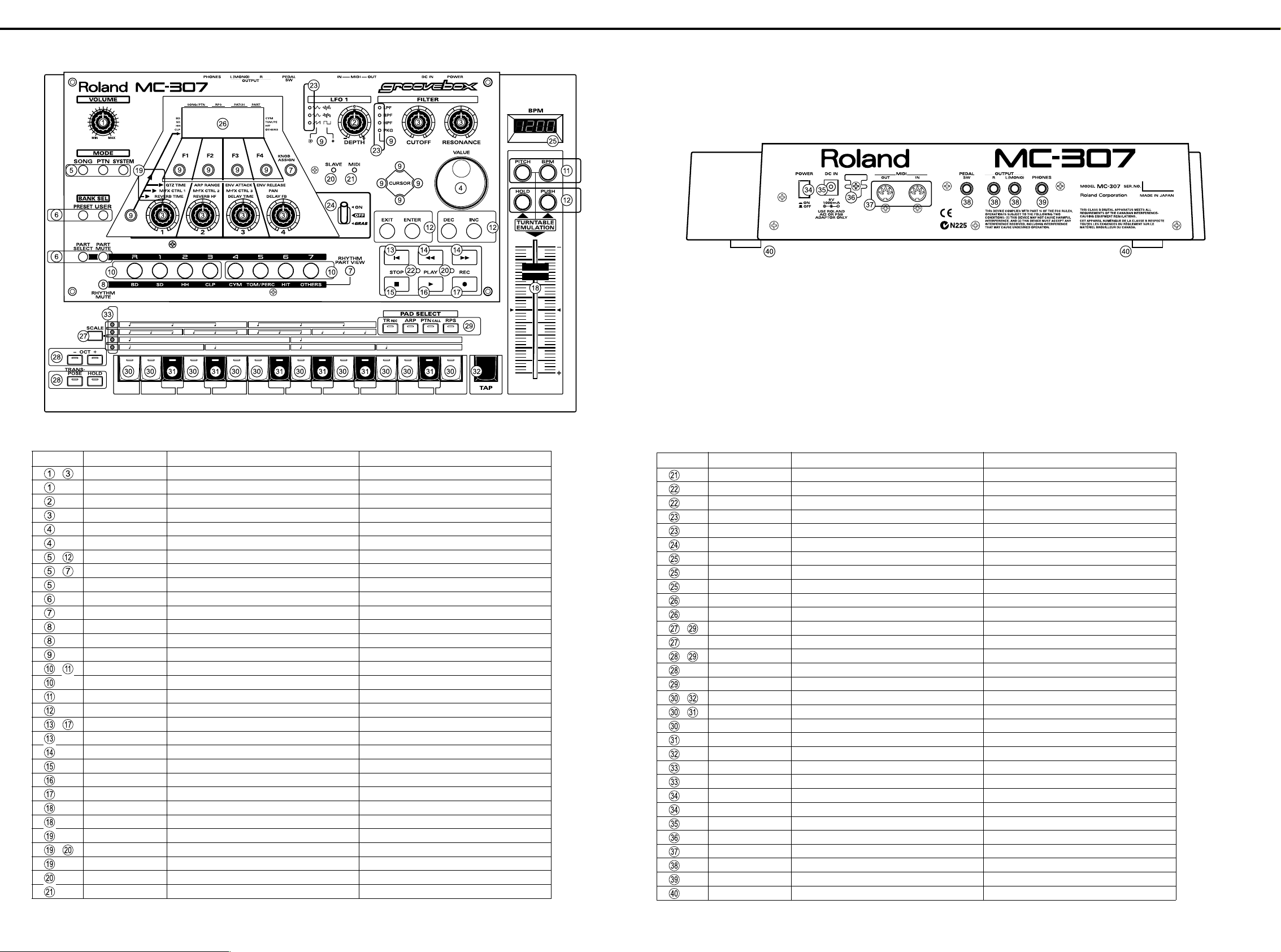
LOCATION OF CONTROLS
panel.eps
/ パネル配置図
/ パネル配置図/ パネル配置図
/ パネル配置図パーツリスト
LOCATION OF CONTROLS PARTS LIST
NO. PART CODE PART NAME DESCRIPTION
~
~
~
~
1
~
1
1
~
1
01343112 J R-KNOB J R-KNOB MF BLK/LCG
01903489 9M/M ROTARY POTENTIOMETER EVJY10F03B14
01670312 9M/M ROTARY POTENTIOMETER EVUJDDFL3B14 W/CLICK&NUT
01670289 9M/M ROTARY POTENTIOMETER EVUJDCFL3B14 W/NUT
22485303 D R-KNOB L BLK 248-303
01905467 ROTARY ENCODER EVE GC1 F20 24B
01340290 TACT SWITCH EVQ11A H=5.0
01787045 LED(ORANGE) SLR-325DCT31
01670478 F C-KEYTOP SX3H CLR
01670489 F C-KEYTOP SX2H CLR
01670490 F C-KEYTOP SX1H CLR
00560745 LED (GREEN) SLR-325MCT31
01670490 F C-KEYTOP SX1H CLR
01670512 F C-KEYTOP SX1H BLK
02011856 LED SLR-56DCT32
01904134 F C-KEYTOP MX4H CLR
01904145 F C-KEYTOP MX2H CLR
01904156 F C-KEYTOP MX2H BLK
00894645 TACT SWITCH SKECAF WITHOUT LED
01904412 KEYTOP RESET
00901423 KEYTOP FWD/RWD(WHIT GREY)
00901390 KEYTOP STOP(WHIT GREY)
00901401 KEYTOP PLAY(WHIT GREY)
00901412 KEYTOP REC(RED)
01904101 J S-KNOB L BLK/LCG
01903778 100M/M SLIDE POTENTIOMETER RSA0N1144(50KB)
01904089 LED LENS
01011656 LED (RED) SLR-332VR3F
00785812 LED SPACER LH-5S-3 (3MM HIGHT)
12169391 LED SPACER LH-5S-10
01012078 LED (GREEN) SLR-332MG3F
/ パネル配置図パーツリスト
/ パネル配置図パーツリスト/ パネル配置図パーツリスト
NO. PART CODE PART NAME DESCRIPTION
12169391 LED SPACER LH-5S-10
00127367 LED (RED/GREEN) SPR-39MVW
01906623 LED SPACER LH-36-8.5
01907901 LED LNJ482YKXXE
01343090 LED SPACER
01348990 LEVER SWITCH LS001-C23OAB-LFA15B
01904090 LED COVER
01903512 7SEG LED LNM223KS01
01904167 LED SPACER FOR 7SEG LED LNM223KS01
01903901 DISPLAY COVER
01896145 LCD RCM6038T-1A
~
~
~
~
01340290 TACT SWITCH EVQ11A H=5.0
00900189 D S-KEYTOP SX1H BLK
00348490 LED (RED) SLR-325VCT31
00900156 D S-KEYTOP SD2H BLK
00900178 D S-KEYTOP SD4H BLK
00125590 TACT SWITCH EVQ QJJ 05Q
02011856 LED SLR-56DCT32
01013356 T S KEYTOP MD1H LCG
22495372 T S KEYTOP MD1H BLK
22495371 T S KEYTOP MX1H BLK
00899023 LED LNJ282RKRXE
01343090 LED SPACER
12499175 G S-BUTTON S1H BLK 249-175
01676512 PUSH SWITCH SDKLA1-B
13449720 DC JACK HEC2305-01-250
22360712 CORD HOOK 236-712
13429825 MIDI CONNECTOR YKF51-5054 2PZ
13449283 6.5MM JACK HLJ7101-01-3010
13449284 6.5MM JACK HLJ7001-01-3010
01235378 FOOT
2
Page 3

JAN, 2000 MC-307
//// 分解図
EXPLODED VIEW
EXPLODED VIEW.eps
分解図
分解図分解図
/ 分解図パーツリスト
EXPLODED VIEW PARTS LIST
NO. PART CODE PART NAME DESCRIPTION Q'TY
01903889 TOP PANEL
71563989 TOP CASE ASSY
01904078 BOTTOM COVER
02015445 SHIELD SHEET
02015456 INSULATING SHEET
71454023 PANEL KEYTOP ASSY
71454045 SLIDER BOARD ASSY
71454012 MAIN BOARD ASSY (EXG)
01906801 STAY
01896145 LCD RCM6038T-1A(W/FLAT CABLE)
01120545 LEAF
02120190 BAN CARD BNCD-P=1.25-K-34-140
02014634 FUJI CARD 18X150-A6.0BBR-P1.25-HBL10
02128834 BAN CARD BNCD-P=1.00-K-16-300
/ 分解図パーツリスト
/ 分解図パーツリスト/ 分解図パーツリスト
NO. PART CODE PART NAME DESCRIPTION Q'TY
40011101 SCREW M3X8 BINDING TAPTITE B FE BZC 3
40011123 SCREW M4X8 BINDING TAPTITE B BZC 7
40344145 SCREW M3X10 P TITE HEX SOCKET HEAD CAP BZC 4
40011267 SCREW M3X6 BINDING TAPTITE P FE ZC 32
40011278 SCREW M3X8 BINDING P-TITE FE ZC 7
40011312 SCREW M3X8 BINDING TAPTITE P FE BZC 2
40233012 SCREW M2.6X8 BINDING TAPTITE FEBZC 3
40011512 SCREW M3X12 SEMS. PAN HEAD FE BZC 1
40011501 SCREW M3X8 PAN MACHINE W/SW FE BZC 3
3
Page 4
MC-307 JAN, 2000
//// パーツリスト
PARTS LIST
SAFETY PRECAUTION:*1
The parts marked have
safety-related characteristics.
Use only listed parts for
replacement.
安全上の注意:*1
が付いている部品は、安全
上特別な規格でつくられたも
のです。
交換の際は、指定された部品
番号以外の部品は使わないよ
うにして下さい。
*1 *2
CASING
# 01904078 BOTTOM COVER 1
# 01903901 DISPLAY COVER 1
01455401 DUST COVER SW 1
# 01903889 TOP PANEL 1
# 71563989 TOP CASE ASSY 1
NOTE: 'TOP CASE ASSY' includes the following parts.
注意 : 補修用 TOP CASE ASSY は、下記の部品を含みます。
# 01903878 TOP CASE 1
# 01904090 LED COVER 1
# 01904089 LED LENS 1
KNOB, BUTTON
01670490 F C-KEYTOP SX1H CLR
01670512 F C-KEYTOP SX1H BLK
00900156 D S-KEYTOP SD2H BLK [OCT-,OCT+],[TRANSPOSE,HOLD] 2
00900178 D S-KEYTOP SD4H BLK [TR REC,ARP,PTN CALL,RPS] 1
00900189 D S-KEYTOP SX1H BLK [SCALE] 1
01670478 F C-KEYTOP SX3H CLR [SONG,PTN,SYSTEM] 1
01670489 F C-KEYTOP SX2H CLR
12499175 G S-BUTTON S1H BLK 249-175 [POWER] 1
01343112 KNOB J R-KNOB MF BLK/LCG
22485303 D R-KNOB L BLK 248-303 [VALUE] 1
# 01904101 J S-KNOB L BLK/LCG [TURN TABLE EMULATION SLIDER] 1
パーツリスト
パーツリストパーツリスト
The parts marked
# are new (initial
parts). *2
# の付いた部品は
新規部品です。
*2
/ ケース
/ ケース
/ ケース / ケース
/ つまみ、ボタン
/ つまみ、ボタン
/ つまみ、ボタン / つまみ、ボタン
CONSIDERATIONS ON PARTS ORDERING
When ordering any parts listed in the parts list . please specify the following items in the ord er sheet.
QTY PART NUMBER DESCRIPTION MODEL NUMBER
Ex 10 22575241 Sharp key C-20/50
15 2247017300 Knob (orange) DA C-15D
Failure to completely fill the above items with correct number and description will result in
delayed or even undelivered replacement.
パーツ発注に関するお願い
オーダーシートには、必ず下記の4項目は正確に記入して下さい。(例外は除く)
必要数 パーツナンバー 品名 使用機種
例) 10 22575241 Sharp key C-20/50
15 2247017300 Knob (orange) DAC-15D
もし記入洩れ、誤記等が有る場合、必要部品が発送できなかったり、大幅な遅れの原因に
なります。御協力をお願いします。
[KNOB ASSIGN],[RHYTHM MUTE],
[RHYTHM PART VIEW]
[F1],[F2],[F3],[F4],[LFO WAVE
SELECT], [FILTER TYPE SELECT],
[CURSOR UP],[CURSOR DOWN],
[CURSOR LEFT],[CURSOR RIGHT],
[KNOB ASSIGNMENT SELECT]
[PRESET,USER],[PART SELECT,PART MUTE]
[VOLUME],[ASSIGNABLE KNOB 1],
[ASSIGNABLE KNOB 2],
[ASSIGNABLE KNOB 3],
[ASSIGNABLE KNOB 4],[DEPTH],
[CUTOFF], [RESONANCE]
Main = Main Board Assy
Panel A = Panel A board
Panel B = Panel B board
Slider = Slider board
7SEG = 7SEG board
Q'ty
11
/ 表示ユニット
DISPLAY UNIT
/ 表示ユニット
/ 表示ユニット / 表示ユニット
01896145 RCM6038T-1A LCD 1
NOTE: Replacement RCM6038T-1A should be made on a unit base.
RCM6038T-1A
注意 :
の交換は、ユニット単位で行って下さい。補修品は、ユニット単位。
# 01903512 LNM223KS01 7SEG LED LED301, LED302 on 7SEG 2
/ 基板完成品
PCB ASSY
/ 基板完成品
/ 基板完成品 / 基板完成品
# 71454012 MAIN BOARD ASSY (EXG) 1
NOTE: 'MAIN BOARD ASSY' includes the following parts.
注意 : 補修用 MAIN BOARD ASSY は、下記の部品を含みます。
22465224 HEAT SINK 246-224 on Main 1
00892234 LEAF SPRING on Main 1
12199584 GROUNDING TERMINAL
M1698 TER1, TER2, TER3, TER4 on Main 4
40011501 SCREW M3X8 PAN MACHINE W/SW FE BZC on Main 1
# 71454023 PANEL KEYTOP ASSY 1
NOTE: 'PANEL KEYTOP ASSY' includes the following parts.
注意 : 補修用 PANEL KEYTOP ASSY は、下記の部品を含みます。
01013356 TS KEYTOP MD1H LCG on Panel B 10
# 01904134 F C-KEYTOP MX4H CLR on Panel A 2
# 01904145 F C-KEYTOP MX2H CLR on 7SEG 1
# 01904156 F C-KEYTOP MX2H BLK on Panel A , on 7SEG 3
# 01904412 KEYTOP RESET on Panel A 1
00901390 KEYTOP STOP(WHIT GREY) on Panel A 1
22495371 TS KEYTOP MX1H BLK on Panel B 1
22495372 TS KEYTOP MD1H BLK on Panel B 6
00901401 KEYTOP PLAY(WHIT GREY) on Panel A 1
3
00901423 KEYTOP FWD/RWD(WHIT GREY) on Panel A 2
00901412 KEYTOP REC(RED) on Panel A 1
# 01906623 LED SPACER LH-36-8.5 on Panel A 1
12169391 LED SPACER LH-5S-10 on Panel A 3
00785812 LED SPACER LH-5S-3 (3MM HIGHT) on Panel A 4
01343090 LED SPACER on Panel A 2
# 01904167 LED SPACER FOR 7SEG LED LNM223KS01 on 7SEG 2
# 71454045 SLIDER BOARD ASSY 1
2
8
SWITCH
/ スイッチ
/ スイッチ
/ スイッチ / スイッチ
01676512 SDKLA1-B PUSH SWITCH SW1 on Main 1
01348990 LS001-C23OAB-LFA15B LEVER SWITCH SW140 on Panel A 1
00894645 SKECAF WITHOUT LED TACT SWITCH SW134-139 on Panel A 6
01340290 EVQ11A H=5.0 TACT SWITCH
SW101-133 on Panel A , SW201-209
on Panel B , SW301-304 on 7SEG
33+9+4
00125590 EVQ QJJ 05Q TACT SWITCH SW210-225 on Panel B 17
/ ジャック、ソケット
JACK, SOCKET
/ ジャック、ソケット
/ ジャック、ソケット / ジャック、ソケット
13429825 YKF51-5054 2PZ MIDI CONNECTOR JK1 on Main 1
13449283 HLJ7101-01-3010 6.5MM JACK JK2, JK5, JK6 on Main 3
13449284 HLJ7001-01-3010 6.5MM JACK JK4 on Main 1
13449720 HEC2305-01-250 DC JACK JK3 on Main 1
4
Page 5

JAN, 2000 MC-307
IC
# 01904212 HD6437016E08F V1.00 IC (32BIT CPU) IC6 on Main 1
01679978
01342978 TC160G22AF-1253 IC (CUSTOM) IC4 on Main 1
01679790 V53C16258HK-35-TP IC (DRAM) IC24 on Main 1
01904489 AS4C1M16E5-60JCTR IC (DRAM) IC9 on Main 1
# 01903190 UPD23C128040LGY-846-MJH IC (MASK ROM) IC16 on Main 1
01561945 LH28F160S5T-L70 IC (FLASH MEMORY) IC7, IC8 on Main 2
01898701 E28F800B5B70 IC (FLASH MEMORY) IC10 on Main 1
01897201 PCM1716E IC (DAC) IC27 on Main 1
15249111 TC7WU04F(TE12L) IC (CMOS) IC22 on Main 1
15249104 TC7S04F(TE85L) IC (CMOS) IC3 on Main 1
15259885 TC7S32F(TE85L) IC (CMOS) IC12 on Main 1
15259884 TC7S08F(TE85L) IC (CMOS) IC28, IC31on Main 2
00127490 TC7W08F(TE12L) IC (CMOS) IC30 on Main 1
15289128 BA10324AF IC (OP AMP) IC29 on Main 1
15289105 UPC4570G2-E2 IC (BIPOLAR OP AMP) IC25 on Main 1
15189261 M5218AFP-600E IC (BIPOLAR OP AMP) IC23, IC26 on Main 2
# 02014645 BA17805T IC (REGULATOR) IC17 on Main 1
01458445 UPC29M33T-T1 IC (REGULATOR) IC15 on Main 1
00344390 TA7805F(TE16L) IC (REGULATOR) IC19 on Main 1
15289404 IR3M03N2-T2 IC (REGULATOR) DC-DC IC21 on Main 1
15199937 M51953BFP-600C IC (RESET) IC14 on Main 1
15289125 PC-410KT 178FAY IC (PHOTO COUPLER) IC5 on Main 1
15169605 TC74HC4052AP IC (C MOS) IC103 on Panel A 1
# 02011878 HD74HC564P IC (CMOS) IC104 on Panel A 1
# 01677790 HD74HC238P IC (CMOS) IC101, IC102 on Panel A 2
# 01677801 HD74HC245PV IC (CMOS) IC201 on Panel B 1
TRANSISTOR / トランジスター
15309101 2SA1037KR T146 QRS TRANSISTOR Q7 on Main 1
15319101 2SC2412KR T146 TRANSISTOR Q8, Q9 on Main 2
15329507 DTA114EKT146 DIGITAL TRANSISTOR Q1, Q12, Q13, Q on Main 3
15329512 DTB123TKT146 DIGITAL TRANSISTOR Q16, Q17 ,Q18 on Main 3
# 02011845 DTD123TKT146 TRANSISTOR Q14, Q15 on Main 2
15329505 DTC314TK T146 DIGITAL TRANSISTOR Q4, Q5, Q6, Q10 on Main 4
15329511 DTC114TKT146 DIGITAL TRANSISTOR Q2, Q3 on Main 2
15329516 DTC114EKT146 TRANSISTOR Q11 on Main 1
15119141 DTA114ESTP DIGITAL TRANSISTOR Q110 - 117 on Panel 8
# 02011867 DTD123TSTP TRANSISTOR Q101- 108 on Panel 8
15129164 DTC114ESTP DIGITAL TRANSISTOR
DIODE / ダイオード
01017512 RB411D T146 SCHOTTKY DIODE D3 on Main 1
15039142 S5688G(TPB5) 1A/400V RECTIFIER DIODE D2 on Main 1
15339138 DCC010-TB DIODE DA1 - 4 on Main 4
15339141 DSD010-TB ARRAY DIODE D1, D5 on Main 2
01565678 RD5.1M-T2B ZENER DIODE D4 on Main 1
15019126 1SS133 T-77 SWITCHING DIODE
# 02011856 SLR-56DCT32 LED
01907901 LNJ482YKXXE LED
01787045 SLR-325DCT31 LED(ORANGE)
00560745 SLR-325MCT31 LED (GREEN) LED133 on Panel A 1
01011656 SLR-332VR3F LED (RED)
01012078 SLR-332MG3F LED (GREEN) LED109 on Panel A 1
00127367 SPR-39MVW LED (RED/GREEN) LED101 on Panel A 1
00348490 SLR-325VCT31 LED (RED) LED201 - 206, 211, 212 on Panel B 8
00899023 LNJ282RKRXE LED LED207 - 210 on Panel B 4
RA09-002XP6TC203C180AF002
/ トランジスター
/ トランジスター / トランジスター
/ ダイオード
/ ダイオード / ダイオード
IC (CUSTOM) IC18 on Main 1
Q109 on Panel A , Q201 - 206 on Panel B
D101 - 139 on Panel A , D201 - 225 on
Panel B, D301 - 304 on 7SEG
LED119 - 122, LED127 - 130 on Panel A ,
LED213 - 228 on Panel B , LED303, 304
on 7SEG
LED107, 108, 115, 116, 123, 124, 132
on Panel A
LED102, 103, 104, 106, 110, 111, 118,
125, 126 on Panel A
LED105, 112, 113, 114, 117, 134 on Panel A
1 +6
39+25+4
8+16+2
RESISTOR / 抵抗
00567023 RPC05T 101 J MTL.FILM RESISTOR
00566867 RPC05T 100 J MTL.FILM RESISTOR R10 on Main 1
00567112 RPC05T 471 J MTL.FILM RESISTOR R15 - 17 on Main 3
00567289 RPC05T 103 J MTL.FILM RESISTOR
01011256 SR73K2ETD 0.47JOHM 1/2W MTL.FILM RESISTOR R35 on Main 1
01011856 RPC05T 0R0 J MTL.FILM RESIST0R R6, 11, 27, 28, 126 on Main 5
00567156 RPC05T 102 J MTL.FILM RESISTOR
15399952 MCR50JZH470 1/2W CHIP RESISTOR R49, 56 on Main 2
00566967 RPC05T 470 J MTL.FILM RESISTOR R99 on Main 1
# 00566990 RPC05T 680 J MTL.FILM RESISTOR R98 on Main 1
00567145 RPC05T 821 J MTL.FILM RESISTOR R85 on Main 1
00566912 RPC05T 220 J MTL.FILM RESISTOR R124, 125 on Main 2
00567034 RPC05T 121 J MTL.FILM RESISTOR R4 on Main 1
00567067 RPC05T 221 J MTL.FILM RESISTOR R1, 2, 20 on Main 3
00567078 RPC05T 271 J MTL.FILM RESISTOR R22, R39 on Main 2
00567134 RPC05T 681 J MTL.FILM RESISTOR R64, 77 on Main 2
00567190 RPC05T 222 J MTL.FILM RESISTOR R37 on Main 1
00567212 RPC05T 332 J MTL.FILM RESISTOR R21 on Main 1
00567245 RPC05T 472 J MTL.FILM RESISTOR R71 on Main 1
00567256 RPC05T 562 J MTL.FILM RESISTOR R48, 55 on Main 2
00567267 RPC05T 682 J MTL.FILM RESISTOR R34, 36, 40 on Main 3
00567501 RPC05T 474 J MTL.FILM RESISTOR R117 - 119 on Main 3
00567290 RPC05T 123 J MTL.FILM RESISTOR R61, 62, 80, 81 on Main 4
00567323 RPC05T 223 J MTL.FILM RESISTOR R59, 73 on Main 2
00567345 RPC05T 333 J MTL.FILM RESISTOR R46, 53, 60, 74 on Main 4
00567378 RPC05T 473 J MTL.FILM RESISTOR R13, 68, 76, 83 on Main 4
00567412 RPC05T 104 J MTL.FILM RESISTOR R51, 52, 57, 58, 66, 67, 82, 84 on Main 8
00567556 RPC05T 105 J MTL.FILM RESISTOR R38 on Main 1
# 01906945 MNR14 E0AB J 101 RESISTOR-ARRAY RA5, 7, 9, 12 on Main 4
# 01906667 MNR14 E0AB J 100 RESISTOR-ARRAY
01566190 EXBE10C473J RESISTOR-ARRAY RA30 on Main 1
01457145 EXBE10C103J RESISTOR-ARRAY RA1, 2, 22, 17 on Main 4
# 01906678 MNR14 E0AB J 103 RESISTOR-ARRAY RA25, 26 - 29 on Main 5
13749757T0 SR25TRE 220 J CARBON RESISTOR R111 - 118 on Panel A 8
13749767T0 SR25TRE 560J CARBON RESISTOR R108 on Panel A 1
13749773T0 SR25TRE 101 J CARBON RESISTOR
13919140 RGLD8X103J RESISTOR ARRAY RA201 on Panel B 1
# 13749763T0 SR25TRE 390 J CARBON RESISTOR R301 - 308 on 7SEG 8
POTENTIOMETER / ボリューム
# 01903489 EVJY10F03B14
01670289 EVUJDCFL3B14
01670312 EVUJDDFL3B14
# 01903778 RSA0N1144(50KB)
7
9
6
/ 抵抗
/ 抵抗 / 抵抗
/ ボリューム
/ ボリューム / ボリューム
9M/M ROTARY POTENTIOMETER
9M/M ROTARY POTENTIOMETER
9M/M ROTARY POTENTIOMETER
100M/M SLIDE POTENTIOMETER
R5, 7, 18, 19, 23, 42 - 45, 65, 78, 93, 94,
116 on Main
R3, 9, 24, 25, 41, 50, 63, 70, 75, 87, 88,
91, 95, 96, 120 on Main
R8, 12, 26, 33, 47, 54, 72, 79, 86, 89,
90, 92, 97, 121 - 123, on Main
RA3, 4, 6, 8, 10, 11, 13 - 15, 18, 20,
21, 23, 24 on Main
R101 - 107, 109 on Panel A ,
R201 - 206 on Panel B
VR108 on Panel A 1
VR101 - 104, 106, 107 on Panel A 6
VR 105 on Panel A 1
VR 401 on Slider 1
14
15
16
14
8+6
5
Page 6
MC-307 JAN, 2000
CAPACITOR / コンデンサー
01674334 ECUV1H101JCV CERAMIC CAPACITOR
00567945 GRM39B103K50PT CERAMIC CAPACITOR
01674712 ECJ1VF1A105Z CERAMIC CAPACITOR
00567978 GRM39F104Z25PT CERAMIC CAPACITOR
01675367 GRM39CH471J50PT CERAMIC CAPACITOR C38 on Main 1
01672412 GRM39CH150J50PT CERAMIC CAPACITOR C39 - 49, 108, 109 on Main 13
01675190 GRM39CH220J50PT CERAMIC CAPACITOR C58, 59 on Main 2
# 01675323 GRM39CH271J50PT CERAMIC CAPACITOR C103 on Main 1
01675234 GRM39CH470J50PT CERAMIC CAPACITOR C118, 123, 135, 144 on Main 4
00567823 GRM39B102K50PT CERAMIC CAPACITOR C121, 132, 174 - 192 on Main 21
13559360 ECQB1181JF3 180PF/100V POLYEST. CAPACITOR C136, 147 on Main 2
# 13549254M0 ECQ-B1H821JF3 POLYEST. CAPACITOR C140, 154 on Main 2
01900834 RA2-16V101M-T2 CHEMICAL CAPACITOR C93, 114, 117, 120, 128, 142 on Main 6
# 02014923 RA2-35V470MT2 CHEMICAL CAPACITOR C138, 139, 148, 152 on Main 4
01900823 RA2-16V100M-T2 CHEMICAL CAPACITOR
01902590 RA2-6V101M-T2 CHEMICAL CAPACITOR
00674423 ECA0JM102B 1000U/6.3V CHEMICAL CAPACITOR C86 on Main 1
13629624S0 6SC10M+T (OS) 6.3V10 CHEMICAL CAPACITOR C105 on Main 1
13639514M0 ECA0JM331B CHEMICAL CAPASITOR C106 on Main 1
13639557M0 ECA1CM102B CHEMICAL CAPACITOR C89 on Main 1
13529132 RPE132-901F104Z50
13639698 ECEA0JKS101B (H=5MM) CHEMICAL CAPACITOR C112 on Panel A 1
13639150M0 ECEA1CKS100B 10UF/16V CHEMICAL CAPACITOR C113, 115 on Panel A 2
INDUCTOR, COIL, FILTER / インダクター、コイル、フィルター
01346089 SBC3-331-551 CHOKE COIL L8, L9 on Main 2
01565612 DSS310-93D223S50 FILTER FL1 on Main 1
01787056 N1608Z102T01 FERRITE-BEAD R14, 100 - 115 on Main 17
01340834 EXCML20A390 FERRITE-BEAD L7 on Main 1
01783601 BLM21B601SPT FERRITE-BEAD L1 - 6, 10 - 16 on Main 13
12449355 FBR07HA850TB00 TAPE INDUCTOR L201 on Panel B 1
CRYSTAL, RESONATOR / クリスタル、発振子
00901912 MA-406 24.576MHZ CRYSTAL X2 on Main 1
01126267 MA-406 7.056MHZ CRYSTAL X1 on Main 1
ENCODER / エンコーダー
01905467 EVE GC1 F20 24B ROTARY ENCODER EN101 on Panel A 1
CONNECTOR / コネクター
# 01902989 52806-1610 CONNECTOR CN1 on Main 1
01787467 52044-3410 CONNECTOR CN5 on Main, CN101on Panel A 1 +1
13379158 IL-FPC-18SL-N FFC CONNECTOR CN6 on Main, CN201on Panel B 1+1
13369601 52147-0610(6P) WIRE TRAP CN4 on Main 1
13369599 52147-0410(4P) WIRE TRAP CN7 on Main 1
13429297 51048-0800(8P) CABLE HOLDER CN104 on Panel A , CN203 on Panel B 1+1
13429295 51048-0600(6P) CABLE HOLDER CN105 on Panel A 1
13429301 51048-1200(12P) CABLE HOLDER
13429298 51048-0900(9P) CABLE HOLDER CN202 on Panel B , CN302 on 7SEG 1+1
13429293 51048-0400(4P) CABLE HOLDER CN401on Slider 1
/ コンデンサー
/ コンデンサー / コンデンサー
/ クリスタル、発振子
/ クリスタル、発振子 / クリスタル、発振子
/ エンコーダー
/ エンコーダー / エンコーダー
/ コネクター
/ コネクター / コネクター
C18, 37, 63, 111, 141, 153, 193 - 201 on Main
C29 - 33, 60, 62, 160 - 164, 169, 173 on Main
C50 - 52, 56, 83, 133, 134, 167, 168,
170 , 171, 202 on Main
C1, 4 - 17, 19 - 21, 23 - 28, 35, 36, 55,
57, 61, 64, 67 - 70, 72 - 74, 76, 77, 79 82, 84, 85, 87, 88, 90, 91, 92, 94 - 100,
102, 104, 107, 110, 112, 113, 115, 116,
122, 124 - 126, 129 - 131, 143, 145, 155
- 157, 159, 165, 166, 203 - 210 on Main
C75, 78, 105, 119, 127, 137, 146, 149 - 151
on Main
C2, 3, 22, 53, 54, 71, 101, 172, 158 on Main
MLT.LAY.CERAMIC CAPACITOR
/ インダクター、コイル、フィルター
/ インダクター、コイル、フィルター / インダクター、コイル、フィルター
C101 - 111, 113, 116 on Panel A , C201,
202 on Panel B , C401 on Slider
CN102, 103 on Panel A , CN204 on
Panel B , CN301 on 7SEG
15
14
12
88
10
13+2+1
2+1+1
WIRING, CABLE / ワイヤリング、ケーブル
# 02014634 FUJI CARD
# 02120190 BAN CARD BNCD-P=1.25-K-34-140 CN101 on Panel A to CN5 on Main 1
# 02128834 BAN CARD BNCD-P=1.00-K-16-300 CN1 on LCD Unit to CN1 on Main 1
# 02011889 RIBBON CABLE 8X50-P2.0
# 02014656 RIBBON CABLE 6X150-P2.0(KOHNO) CN105 on Panel A to CN4 on Main 1
# 01906634 RIBBON CABLE 9X150-P2.0 CN202 on Panel B to CN302 on 7SEG 1
# 01906889 RIBBON CABLE 12X50-P2.0
# 02014690 RIBBON CABLE 4X60-P2.0(KOHNO) CN401 on Slider to CN7 on Main 1
SCREW / ねじ類
40233012 SCREW M2.6X8 BINDING TAPTITE FEBZC 3
# 40344145 SCREW M3X10
40011512 SCREW M3X12 SEMS. PAN HEAD FE BZC 1
40011267 SCREW M3X6 BINDING TAPTITE P FE ZC 32
40011101 SCREW M3X8 BINDING TAPTITE B FE BZC 3
40011312 SCREW M3X8 BINDING TAPTITE P FE BZC 2
40011278 SCREW M3X8 BINDING P-TITE FE ZC 6
40011501 SCREW M3X8
40011123 SCREW M4X8 BINDING TAPTITE B BZC 7
PACKING / 梱包材
9
# 01906901 ADAPTOR PAD 1
# 01904045 UPPER PAD L 1
# 02016112 LOWER PAD L 1
# 01904056 UPPER PAD R 1
# 02016134 LOWER PAD R 1
# 01904023 PACKING CASE 1
/ ねじ類
/ ねじ類 / ねじ類
/ 梱包材
/ 梱包材 / 梱包材
MISCELLANEOUS
22360712 CORD HOOK 236-712 1
01235378 FOOT 4
01120545 LEAF XP-80LEAF 3
# 02015445 SHIELD SHEET 1
# 02015456 INSULATING SHEET 1
# 01906801 STAY 1
ACCESSORIES (STANDARD) / 標準付属品
01901578 AC ADAPTOR PSB-1U UNIVERSAL 1+1
01018312 AC ADAPTOR ACI-230C 1
00905767 AC ADAPTOR ACI-120C 1+1
00905756 AC ADAPTOR ACI-100C 1
01903367 AC CORD SET 240V 1.0M FOR PSB 1
01903356 AC CORD SET 230V 1.0M FOR PSB 1
00905234 EURO CONVERTER PLUG
# 71454923 OWNER'S MANUAL ENGLISH 1
# 71453990 OWNER'S MANUAL JAPANESE 1
40232334
/ ワイヤリング、ケーブル
/ ワイヤリング、ケーブル / ワイヤリング、ケーブル
/ その他
/ その他
/ その他 / その他
/ 標準付属品
/ 標準付属品 / 標準付属品
保証書
18X150-A6.0BBR-P1.25-HBL10
P TITE HEX SOCKET HEAD CAP BZC
PAN MACHINE W/SW FE BZC
ECP01-5A (PLUG FOR BRC-230T)
JAPAN ONLY 1
CN201 on Panel B to CN6 on Main 1
CN104 on Panel A to CN203 on Panel B
CN103 on Panel A to CN204 on Panel B ,
CN102 on Panel A to CN301 on 7SEG
on Main 3
1
2
4
1
6
Page 7
JAN, 2000 MC-307
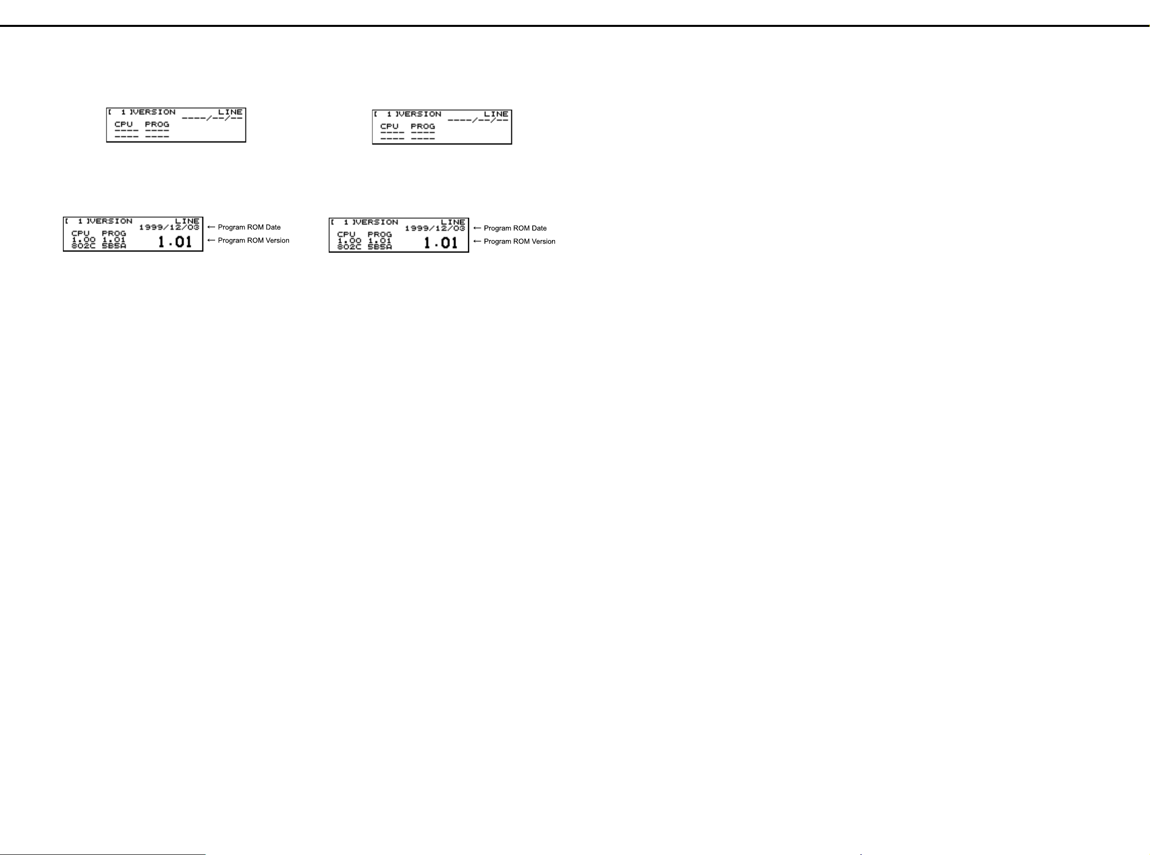
CONFIRMING THE VERSION
Turn the power to on while holding down [SONG], [SYSTEM] and [BPM].
Test mode program starts and, after a while, the following screen appears
on the LCD.
After entering the test mode, the program automatically starts VERSION test.
Checks version of CPU/Program ROM.
It takes same time until all the contents are displayed because it is necessary to calculate checksum.
The contents are shown as follows.
The screen displays the following items.
Version of CPU (CPU Internal ROM)
•
Checksum of CPU (CPU Internal ROM)
•
Version of Program ROM...It is shown also with large characters.
•
Checksum of Program ROM
•
Date of release of Program ROM
•
Turn off the power after the above confirmation.
バージョンの確認の方法
バージョンの確認の方法
バージョンの確認の方法バージョンの確認の方法
[SONG] + [SYSTEM] + [BPM] を押しながら Power を ON にします。テス
トモードプログラムが起動し、しばらくすると LCD に次の初期画面
が表示されます。
テストモードに入ると、自動的に VERSION テストを開始します。
CPU/Program ROM のバージョンをチェックします。
Checksum の計算をするため、すべての内容が表示されるまでに多少の
時間がかかります。
下記のように表示されます。
画面には以下のものが表示されます。
・CPU (CPU Internal ROM) バージョン
・CPU (CPU Internal ROM) チェックサム
・Program ROM バージョン ... 大きい文字でも表示されます。
・Program ROM チェックサム
・Program ROM リリース日付
確認後、POWER を OFF にして下さい。
RECORDING THE DATA OF ALL MC-307 DATA ON AN EXTERNAL SEQUENCER
Before you begin, use a MIDI cable to connect the MIDI OUT of the
MC-307 to the MIDI IN of the external sequencer MC-80.
Procedure
1. Press the [SYSTEM] button, and then the [F2 (UTIL)] button.
2. Press the [CURSOR(up)] button.
The "3 BULK DUMP" screen will appear.
3. Press the [F3 (BULK)] button.
4. Press the [F3 (TXAL)] button.
The "BULK TX USER ALL" screen will appear.
5. Start realtime recording on your external MIDI sequencer.
6. On the MC-307, press [F4 (EXEC)].
Bulk data will be transmitted from MIDI OUT.
When the data has been transmitted, you will return to the pattern
screen.
7. Stop recording on your external MIDI sequencer.
The bulk data will be transmitted with the device ID number specified.
Restoring data for all MC-307 data from a MIDI sequencer back to the MC-307
To restore previously saved bulk data back to the MC-307, use the following procedure.
Before you begin, use a MIDI cable to connect the MIDI IN of the MC307 to the MIDI OUT of your external sequencer.
Procedure
1. Press the [SYSTEM] button and then the [F2 (UTIL)] button.
2. Press the [CURSOR(up)] button.
The "3 BULK DUMP" screen will appear.
3. Press the [F3 (BULK)] button.
4. Press the [F4 (RX AL)] button
The "BULK RECEIVE" screen will appear. The MC-307 will be ready to
receive bulk data.
5. Transmit bulk data from the external device.
6. When the external device has finished transmitting the data, You will
return to pattern play screen.
MC-307 の全データを外部シーケン
MC-307 の全データを外部シーケン
MC-307 の全データを外部シーケンMC-307 の全データを外部シーケン
サーに記録する
サーに記録する
サーに記録するサーに記録する
あらかじめ、MC-307 の MIDI OUT と外部シーケンサー MC-80 の MIDI
IN を MIDI ケーブルで接続しておきます。
操作手順
操作手順
操作手順操作手順
1.[SYSTEM]-[F2(UTIL)]の順にボタンを押します。
2.[CURSOR(上)]ボタンを押します。
"3 BULK DAMP" 画面が表示されている画面になります。
3.[F3(BULK)]ボタンを押します。
4.[F3(TXAL)]ボタンを押します。
"BULK TX USER ALL" 画面が表示されます。
5. 外部 MIDI シーケンサーのリアルタイム・レコーディングをスタート
します。
6. MC-307 の[F4(EXEC)]を押します。
MIDI OUT からバルク・データが送信されます。
データの送信が終わると、パターンを再生する画面に戻ります。
7. 外部 MIDI シーケンサーの録音を停止します。
デバイス ID で設定されているデバイス ID ナンバーで、バルクデータ
は送信されます。
MC-307 の全データを MIDI シーケン
MC-307 の全データを MIDI シーケン
MC-307 の全データを MIDI シーケンMC-307 の全データを MIDI シーケン
サーから MC-307 に戻す
サーから MC-307 に戻す
サーから MC-307 に戻すサーから MC-307 に戻す
保存したバルク・データを MC-307 に戻すには、次の操作を行 います。
あらかじめ、MC-307 の MIDI IN と外部シーケンサーの MIDI OUT を
MIDI ケーブルで接続します。
操作手順
操作手順
操作手順操作手順
1.[SYSTEM]-[F2(UTIL)]の順にボタンを押します。
2.[CURSOR(上)]ボタンを押します。
"3 BULK DAMP" 画面が表示されている画面になります。
3.[F3(BULK)]ボタンを押します。
4.[F4(RX AL)]ボタンを押します。
"BULK RECEIVE" 画面が表示されます。MC-307 はバルク・データを 受
信できる状態になります。
5. 外部機器からバルクデータを送信します。
6. 外部機器の送信が終了したら、パターンを再生する画面に戻ります。
RESTORING THE FACTORY SETTINGS (FACTORY RESET)
This operation can restore all settings of the MC-307 to those factory
default settings.
Caution: If any valuable data reside in the MC-307 main memory, save
the data into an external MIDI sequencer or other external
devices before executing factory reset.
Operating procedure
1. Press the [SYSTEM] button.
The menu screen for system set-up appears.
2. Press the [F2 (UTIL)] button.
3. Press the [CURSOR (down)] button.
The screen containing the "5 FACTORY RESET" screen appears.
4. Press [F1 (FACT)] button.
The "FACTORY RESET" screen appears and the "ARE YOU SURE?"
message is displayed.
5. Press [F4 (EXEC)] button to execute factory reset.
It takes about 6 minutes to complete and the "COPMPLETED!" message appears.
After a while, pattern play screen appears.
製品出荷時の状態に戻す
製品出荷時の状態に戻す
製品出荷時の状態に戻す製品出荷時の状態に戻す
(FACTORY RESET)
(FACTORY RESET)
(FACTORY RESET)(FACTORY RESET)
MC-307 のすべての設定を、製品出荷時の設定に戻すことができます。
注意:MC-307 の本体内に大切なデータがあるときは、ファクトリー・
リセットを実行する前にバルク・ダンプの操作で外部 MIDI
シーケンサーなどにデータを保存してください。
操作手順
操作手順
操作手順操作手順
1.[SYSTEM]ボタンを押します。
システム設定のメニュー画面が表示されます。
2.[F2(UTIL)]ボタンを押します。
3.[CURSOR(下)]ボタンを押します。
"5 FACTORY RESET" 画面が表示されている画面になります。
4.[F1(FACT)]ボタンを押します。
"FACTORY RESET" 画面が表示され、「ARE YOU SURE?」(ほんとうに実行
してもいいですか?)と表示がでます。
[F4(EXEC)]ボタンを押すと、ファクトリー・リセットが実行されます。
5.
約 6 分で完了し、「COMPLETED!」と表示されます。
その後しばらくすると、電源投入時の画面に戻ります。
7
Page 8

MC-307 JAN, 2000
VERSION-UP
Outline
MC-307 uses 16 Mbit flash memory for program (system), and 16 Mbit
•
flash memory for data (Note).
Updata (control program) of the flash memories are stored in the CPU
•
(SH-2).
Data for update are provided usually as SMF data that consist of sev-
•
eral divisions.
By combining a sequencer that can regenerate SMF data (such as
MC-80) and MC-307, and by loading the data into MC-307, the version
of program or data can be updated.
Note:
After updating the data, factory reset is required.
•
Since the user’s data are reset at this time, it is necessary to make a
backup of the user ’s data beforehand. Details are described in the sections describing the data saving and loading.
From a certain lot, program and data are delivered at the same time by
•
32 bit mask ROM that is installed in the unit.
For the board on which the mask ROM is installed, the program and
data cannot be updated.
Required items
MC-307 and its AC adaptor
•
Sequencer that is capable of regenerating SMF (such as MC-80)
•
MIDI cable
•
SMF data disks for update (2HD): #17048493
•
Two disks for program, and two disks for data
Individual disks contain files as described below.
(Note)File names are the same after the version is changed.
Program (system) update disk
Disk for Program #1(1/2)
SYS4MC_1.SVC (Chain file for MC-80)
SYS4XP_1.SVC (Chain file for XP-50, 60, and 80)
S0000001.MID
S0000002.MID
S0000003.MID
S0000004.MID
S0000005.MID
S0000006.MID
S0000007.MID
S0000008.MID
S0000009.MID
S0000010.MID
S0000011.MID
S0000012.MID
S0000013.MID
S0000014.MID
S0000015.MID
S0000016.MID
バージョンアップの方法
バージョンアップの方法
バージョンアップの方法バージョンアップの方法
◯
概要
概要
概要概要
・ MC -307はプログラム ( システム ) 用に 16Mbit、データ用に
16Mbit のフラッシュメモリ ( 注 ) を使用しています。
・ フラッシュメモリのアップデータ ( 制御プログラム ) は CPU(SH
-2 ) の内部に格納されています。
・ アップデート用のデータは通常、複数に分割された SMF データで
提供されます。
SMF データを再生可能なシーケンサ (MC -80など ) と MC -
307を接続し、MC -307にロードすることでプログラムや
データのバージョンを更新することができます。
注意:
注意:
注意:注意:
・
データをアップデートした場合、ファクトリーリセットが必要になります。
その際ユーザデータがリセットされるため、前もってバックアップを
とっておく必要があります。詳細はデータのセーブとロードの項目に
記載されています。
・ あるロット以降ではフラッシュメモリのかわりに 32Mbit のマスク
ROM が実装されプログラムとデータが合わせて格納されます。
→ マスク ROM が実装されているボードの場合、プログラム、データ
のアップデートは行えません。
◯
用意するもの
用意するもの
用意するもの用意するもの
・ MC -307本体と AC アダプタ
・ SMF 再生可能なシーケンサ (MC -80など )
・ MIDI ケーブル
・ アップデート用 SMF データディスク ( 2HD):#17048493
→ プログラム用2枚、データ用2枚
各ディスクに入っているファイルは以下の通り。
( 注意 ) ファイル名はバージョンが変わっても同じです。
プログラム ( システム ) アップデート用ディスク
Disk for Program #1(1/2)
SYS4MC_1.SVC (MC -80用チェーンファイル )
SYS4XP_1.SVC (XP -50、60、80用チェーンファイル )
S0000001.MID
S0000002.MID
S0000003.MID
S0000004.MID
S0000005.MID
S0000006.MID
S0000007.MID
S0000008.MID
S0000009.MID
S0000010.MID
S0000011.MID
S0000012.MID
S0000013.MID
S0000014.MID
S0000015.MID
S0000016.MID
Disk for Program #1(2/2)
SYS4MC_2.SVC (Chain file for MC-80)
SYS4XP_2.SVC (Chain file for XP-50, 50, and 80)
S0000017.MID
S0000018.MID
S0000019.MID
S0000020.MID
S0000021.MID
S0000022.MID
S0000023.MID
S0000024.MID
S0000025.MID
S0000026.MID
S0000027.MID
S0000028.MID
S0000029.MID
S0000030.MID
S0000031.MID
S0000032.MID
Data update disk
Disk for Data #1(1/2)
DAT4MC_1.SVC (Chain file for MC-80)
DAT4XP_1.SVC (Chain file for XP-50, 50, and 80)
D0000001.MID
D0000002.MID
D0000003.MID
D0000004.MID
D0000005.MID
D0000006.MID
D0000007.MID
D0000008.MID
D0000009.MID
D0000010.MID
D0000011.MID
D0000012.MID
D0000013.MID
D0000014.MID
D0000015.MID
D0000016.MID
Disk for Data #1(2/2)
DAT4MC_2.SVC (Chain file for MC-80)
DAT4XP_2.SVC (Chain file for XP-50, 50, and 80)
D0000017.MID
D0000018.MID
D0000019.MID
D0000020.MID
D0000021.MID
D0000022.MID
D0000023.MID
D0000024.MID
D0000025.MID
D0000026.MID
D0000027.MID
D0000028.MID
D0000029.MID
D0000030.MID
D0000031.MID
D0000032.MID
Disk for Program #1(2/2)
SYS4MC_2.SVC (MC -80用チェーンファイル )
SYS4XP_2.SVC (XP -50、60、80用チェーンファイル )
S0000017.MID
S0000018.MID
S0000019.MID
S0000020.MID
S0000021.MID
S0000022.MID
S0000023.MID
S0000024.MID
S0000025.MID
S0000026.MID
S0000027.MID
S0000028.MID
S0000029.MID
S0000030.MID
S0000031.MID
S0000032.MID
データアップデート用ディスク
Disk for Data #1(1/2)
DAT4MC_1.SVC (MC -80用チェーンファイル )
DAT4XP_1.SVC (XP -50、60、80用チェーンファイル )
D0000001.MID
D0000002.MID
D0000003.MID
D0000004.MID
D0000005.MID
D0000006.MID
D0000007.MID
D0000008.MID
D0000009.MID
D0000010.MID
D0000011.MID
D0000012.MID
D0000013.MID
D0000014.MID
D0000015.MID
D0000016.MID
Disk for Data #1(2/2)
DAT4MC_2.SVC (MC -80用チェーンファイル )
DAT4XP_2.SVC (XP -50、60、80用チェーンファイル )
D0000017.MID
D0000018.MID
D0000019.MID
D0000020.MID
D0000021.MID
D0000022.MID
D0000023.MID
D0000024.MID
D0000025.MID
D0000026.MID
D0000027.MID
D0000028.MID
D0000029.MID
D0000030.MID
D0000031.MID
D0000032.MID
8
Page 9

JAN, 2000 MC-307
Updating procedure
Procedure common to updating program and data
1. Connect the power cords of individual units to be used, and check that
the power can be turned on.
2. If necessary, confirm the version of MC-307 before updating.
3. Use MIDI cable to connect MIDI-OUT of the sequencer and MIDI-IN of
MC-307.
4. Turn on the power while holding down [F1], [F4] and [RHYTHM PART
VIEW] buttons.
[----] appears on the BPM display section.
Now, perform the following procedure in accordance with the contents
(item program or data) to be updated.
Updating program
1. Press buttons [R] and [3] in this order.
2. [SyS] appears on the BPM display section.
3. SMF data for updating are loaded from the sequencer.
32 files from S0000001.MID to S0000032.MID are regenerated in this
order.
Updating data
1. Press buttons [5] and [7] in this order.
2. [dAt] appears on BPM display section.
3. SMF data for updating are loaded from the sequencer.
32 files from D0000001.MID to D0000032.MID are regenerated in this
order.
◯
アップデート手順
アップデート手順
アップデート手順アップデート手順
●
プログラム、データ共通手順
プログラム、データ共通手順
プログラム、データ共通手順プログラム、データ共通手順
1.
使用する各機器の電源コードを接続し、電源が入ることを確認して下さい。
2.必要であればアップデート前の MC -307のバージョンを確認して
おいて下さい。
3.シーケンサの MIDI-OUT と MC -307の MIDI-IN を MIDI ケーブルで
接続して下さい。
4.[F1] ボタン、[F4] ボタン、[RHYTHM PART VIEW] ボタンをおしながら電
源を入れます。
BPM 表示部に [----] と表示されます。
以下、アップデートしたい内容 ( プログラムまたはデータ ) に応じて手
順を進めます。
●
プログラムのアップデート
プログラムのアップデート
プログラムのアップデートプログラムのアップデート
1.[R],[3] の順にボタンを押します。
2.BPM 表示部に [ SyS] と表示されます。
3.シーケンサからアップデート用の SMF データをロードします。
S0000001.MID ~ S0000032.MID の32ファイルを番号順に再生させます。
●
データのアップデート
データのアップデート
データのアップデートデータのアップデート
1.[5],[7] の順にボタンを押します。
2.BPM 表示部に [ dAt] と表示されます。
3.シーケンサからアップデート用の SMF データをロードします。
D0000001.MID ~ D0000032.MID の32ファイルを番号順に再生させます。
Corrective actions to be taken in case the unit
cannot be started
Outline
MC-307 is equipped with a flash memory to store the data created by
•
the user. In case the power is turned off accidentally while the data are
written into this flash memory, it may be possible that the unit cannot
be started normally according to the damage to the flash memory, such
as stopping at the starting screen.
In such case, the unit cannot be restored to normal state only by performing the version-up operation, but it can be restored to normal state
by performing the version-up operation after initializing the flash memory. However, the user’s data are lost in such occasion.
1. Turn on the power while holding down [F1], [F4] and [RHYTHM PART
VIEW].
[----] appears on BPM display section.
2. Press [1] and [6] buttons in this order.
3. [tESt] appears on BPM display section.
4. Initialization of the flash memory starts automatically.
5. BPM display section shows [tSt1], [tSt2], [tSt3] and [ End] in this order.
[ End] appears when initialization of the flash memory is completed.
It takes approximately 3 minutes to complete the initialization.
6. After initializing the flash memory by going through the above steps,
version-up both program and data.
◯
起動できなくなった場合の対処法
起動できなくなった場合の対処法
起動できなくなった場合の対処法起動できなくなった場合の対処法
●
概要
概要
概要概要
・ MC -307はユーザの作成したデータを保存するためのフラッシュ
メモリを搭載しています。このフラッシュメモリにデータを書き込み
中に誤って電源を切ってしまうと、フラッシュメモリの壊れ方によっ
ては起動画面で止まってしまうなど、正常に起動できなくなる場合が
あります。
この場合、バージョンアップ作業を実行しただけでは正常な状態に戻
りませんが、ラッシュメモリの初期化を行ってからバージョンアップ
作業を実行することで正常な状態に戻すことができます。ただし、
ユーザデータは消えてしまいます。
1.[F1],[F4],[RHYTHM PART VIEW] をおしながら電源を入れます。
BPM 表示部に [----] と表示されます。
2.[1] ボタン ,[6] ボタンを順に押します。
3.BPM 表示部に [tESt] と表示されます。
4.自動的にフラッシュメモリの初期化を行います。
BPM 表示部に [tSt1] → [tSt2] → [tSt3] → [ End] の順に表示されます。
5.
[ End] と表示されればフラッシュメモリの初期化は完了です。
所要時間は約3分です。
6.上記手順でフラッシュメモリの初期化後、プログラムとデータの両方
のバージョンアップを行って下さい。
Operation of panel during updating
During the data loading, MIDI indicator (green LED) goes on and off, and
part mute buttons are lit in the order from R, 1, to 7. Then, SLAVE indicator (red LED) goes on and then off. Loading of one file is completed now.
It takes about approximately 40 seconds to load one SMF file.
After all the files are updated, turn off the power and then on to confirm
the version and checksum.
After data is updated, perform factory reset.
Updating when chain file can be used
If any of the following model is available as a sequencer for regeneration
of SMF file, the time for updating can be shortened by automatically playing the disk files (16 files) using the chain play function.
MC-80
XP-50
XP-60
XP-80
Use chain files corresponding to the sequencer model.
These files are made to chain-play SMF files (16 files) stored in individual
disks.
For the operation of the sequencer, refer to the operation manual of the
model.
●
アップデート中のパネル動作
アップデート中のパネル動作
アップデート中のパネル動作アップデート中のパネル動作
データのロード中は MIDI インジケータ ( 緑 LED) が点滅し、パートボタン
が R、1~7の順に点灯していき ます 。その後、SLAVE( 赤 LED) インジ
ケータが点灯して消灯します。これで1ファイルのロ ード が完了 しま す。
SMF ファイル1つをロードするのに、約40秒かかります。
アップデート作業がすべて完了した後、電源を入れなおしてバージョン
とチェックサムを確認して下さい。
データをアップデートした場合は、ファクトリーリセットを行って下さい。
●
チェーンファイルを使用できる場合のアップデート
チェーンファイルを使用できる場合のアップデート
チェーンファイルを使用できる場合のアップデートチェーンファイルを使用できる場合のアップデート
SMF ファイル再生用シーケンサとして、以下の機種が用意できる場合、
チェーンプレイ機能によって各ディスクのファイル (16 ファイル ) を自
動連奏することで、アップデート作業を効率よく行うことが出来ます。
MC -80
XP -50
XP -60
XP -80
各ディスクに入っている各機種対応のチェーンファイルを使用して下さい。
これらのファイルは、各ディスク中の SMF ファイル (16 ファイル )
をチェーンプレイするように作成されています。
操作方法は、各機種の取扱説明書をご覧下さい。
9
Page 10

MC-307 JAN, 2000
OPERATION FOR TEST MODE
1 Required items
MIDI cable
•
Foot pedal (such as DP-2)
•
Monitor speaker set (such as MA-12)
•
2 Entering the TEST MODE
2.1 Connect the monitor speaker to OUTPUT.
2.2 Turn on the power while holding down [SONG], [SYSTEM] and
[BPM. Test mode program starts and, after a while, the following
screen appears on the LCD.
3 Exiting the TEST MODE
Turn the power switch to OFF.
(Caution) Do not turn the power switch to OFF during the execution of
the test item 10. Factory Reset, that is described later in this manual.
テストモード操作法
テストモード操作法
テストモード操作法テストモード操作法
□ 1 用意するもの
□ 1 用意するもの
□ 1 用意するもの□ 1 用意するもの
・MIDI ケーブル
・フットペダル (DP-2 等 )
・モニタースピーカー (MA-12 等 )
□ 2 テストモードへの入りかた
□ 2 テストモードへの入りかた
□ 2 テストモードへの入りかた□ 2 テストモードへの入りかた
2.1モニタースピーカーを OUTPUT につないでください。
2.2 [SONG] + [SYSTEM] + [BPM] を押しながら Power を ON にします。
テストモードプログラムが起動し、しばらくすると LCD に次の
初期画面が表示されます。
□ 3 テストモードの抜けかた
□ 3 テストモードの抜けかた
□ 3 テストモードの抜けかた□ 3 テストモードの抜けかた
POWER スイッチを OFF にする。
( 注意 ) 後述の、テスト項目 10 FACTORY RESET を実行中は
POWER スイッチを OFF にしないで下さい。
6 Confirmation of test results
Numbers corresponding to individual test items are displayed with the seven
segment display section on the upper part of LCD. The numbers go off when
the test items corresponding to the numbers are completed normally.
7 Proceeding with TEST MODE
7.1 VERSION test
When entering the TEST MODE, VERSION is started automatically.
Version of CPU/Program ROM is checked.
It takes some time until all the contents are displayed because of
calculation of checksum.
Press [F4] or [RIGHT] to move to the next test.
VERSION 1.01: Takes some time until the test process is switched.
VERSION 1.02 and after: The test process is switched quickly.
The screen displays the following items.
Version of CPU (CPU Internal R OM)
•
Checksum of CPU (CPU Internal ROM)
•
Version of Program ROM...It is shown also with large characters.
•
Checksum of Program ROM
•
Date of release of Program ROM
•
□ 6 テスト結果の確認
□ 6 テスト結果の確認
□ 6 テスト結果の確認□ 6 テスト結果の確認
LCD 上部の 7Seg 表示部にテスト項目に対応する番号が表示されます。
テストの結果が正常な場合、対応する項目の番号が消えます。
□ 7 テストモードの進め方
□ 7 テストモードの進め方
□ 7 テストモードの進め方□ 7 テストモードの進め方
7.1 VERSION テスト
○ テストモードに入ると、自動的に VERSION テストを開始します。
○ CPU/Program ROM のバージョンをチェックします。
○ Checksum の計算をするため、すべての内容が表示されるまでに多
少の時間がかかります。
○ [F4] または [RIGHT] を押して次のテストに進みます。
VERSION 1.01 : 切り替わるまでに多少時間がかかります。
VERSION 1.02 以降 : すぐに切り替わります。
画面には以下のものが表示されます。
・CPU (CPU Internal ROM) バージョン
・CPU (CPU Internal ROM) チェックサム
・Program ROM バージョン ... 大きい文字でも表示されます。
・Program ROM チェックサム
・Program ROM リリース日付
4 Basic operations in TEST MODE
4.1 Basic operations of controls are as described below.
[F1] or [LEFT] Goes back to previous test screen
[F4] or[RIGHT] Moves to the next test screen.
[ENTER] Performs the test.
[SYSTEM] and [F1] Goes to Test Menu screen.
4.2 For some test items, the test process advances automatically to the
next item when the current test item is completed successfully. For
such items, "OK!" appears when the result of the test is normal. In
case the result of the test is abnormal, "NG!" and the contents of the
abnormality are displayed, and the test process does not move to
the next item. If the process is ended at a test item, it does not move
to the next test item automatically.
4.3 A test item can be selected directly on the test menu screen.
Use [INC] or [DEC] to select a test item and press [F4] or [ENTER]
to display the screen of the selected test item.
5 Test items
The following 10 test items are available.
1 VERSION TEST
2 DEVICE TEST (auto 1)
3 EFFECT TEST (auto 1)
4 MIDI TEST (auto 2)
5 A/D TEST (auto 2)
6 PEDAL TEST (auto 2)
7SW/LED TEST
8 LCD/ENCODER TEST
9 SOUND TEST
10FACTORY RESET
□ 4 テストモードの基本操作
□ 4 テストモードの基本操作
□ 4 テストモードの基本操作□ 4 テストモードの基本操作
4.1 操作子の基本操作は下記の様になります。
[F1]or[LEFT] 1つ前のテスト画面へ
[F4]or[RIGHT] 1つ後のテスト画面へ
[ENTER] テストの実行
[SYSTEM]+[F1] Test Memu 画面へ
4.2 テスト項目には、テスト結果が正常な場合に自動的に次のテスト
に移行するものがあります。このテスト項目では、テスト結果が
正常な場合には "OK!" が表示されます。
テスト結果が異常な場合には "NG!" 及び異常の内容が表示され、
次のテストには移行しません。
一度テストを終了した後では、次のテスト項目に自動的には移行
しません。
4.3 テストメニュー画面でテスト項目を直接選ぶことができます。
[INC]/[DEC] 等でテスト項目を選び [F4]/[ENTER] を押すと、選択
したテスト項目画面になります。
□ 5 テスト項目
□ 5 テスト項目
□ 5 テスト項目□ 5 テスト項目
下記の 10 項目をテストします。
1 VERSION TEST
2 DEVICE TEST (auto 1)
3 EFFECT TEST (auto 1)
4 MIDI TEST (auto 2)
5 A/D TEST (auto 2)
6 PEDAL TEST (auto 2)
7 SW/LED TEST
8 LCD/ENCODER TEST
9 SOUND TEST
10 FACTORY RESET
7.2 DEVICE test
Individual devices are tested; CPU ROM/RAM, Program ROM, Pattern ROM, User Flash Memory, and DRAM.
It takes some time until the test results are displayed.
When the test result is normal, the process moves to the next test
automatically.
If the test result is abnormal, the name(s) of defective device(s) is
displayed.
(When the test result is normal)
(If the test result is abnormal)
7.3 EFFECT test
RAM in DSP of synthesis chip (XP chip) and DRAM for EFFECT
are tested.
When the test result is normal, the process moves to the next test
automatically.
If the test result is abnormal, the name(s) of defective device(s) is
displayed.
(When the test result if normal)
(If the test result is abnormal)
7.2 DEVICE テスト
○各種デバイス (CPU ROM/RAM, Program ROM, Pattern ROM, User
Flash Memory, DRAM) のテストをします。
○ テストの結果が表示されるまでに多少の時間がかかります。
○ テスト結果が正常な場合には、自動的に次のテストに進みます。
○ テスト結果が異常な場合には、異常があったデバイス名が表示さ
れます。
(テスト結果が正常な場合)
(テスト結果が異常な場合)
7.3 EFFECT テスト
○ 音源 Chip (XP Chip) の DSP 内部 RAM、EFFECT 用 DRAM のテスト
をします。
○ テスト結果が正常な場合には、自動的に次のテストに進みます。
○ テスト結果が異常な場合には、異常があったデバイス名が表示さ
れます。
(テスト結果が正常な場合)
(テスト結果が異常な場合)
* The test item shown with (auto 1) is the item for which the test process
moves automatically to the next item when the result of t he test is normal.
* The test item shown with (auto 2) is the item performed manually, and
the test process moves automatically to the next item when the result
of the test is normal.
10
※ (auto 1) とあるテストは、テストを自動実行し、テスト結果が正常
な場合に自動的に次のテスト項目に移行するものです。
※ (auto 2) とあるテストは、作業者がテストを実行し、テスト結果が
正常な場合に自動的に次のテスト項目に移行するものです。
Page 11

JAN, 2000 MC-307
7.4 MIDI test
Conductivity of MIDI is tested.
Use MIDI cable to connect MIDI IN and MIDI OUT.
The following screen appears.
Before connecting the cable
After connecting the cable
Disconnect MIDI cable.
If MIDI is normal, the process moves to the next test.
7.5 A/D test
A/D is tested.
When the test result is normal, the process moves to the next test
automatically.
If the test result is abnormal, the process does not move to the next test.
The following screen appears.
Test items
1 (KNOB1) Confirm changes from 0 through 127.
•
(A sound is generated at 0 and 127 respectively.)
2 (KNOB2) Confirm changes from 0 through 127.
•
(A sound is generated at 0 and 127 respectively.)
3 (KNOB3) Confirm changes from 0 through 127.
•
(A sound is generated at 0 and 127 respectively.)
4 (KNOB4) Confirm changes from 0 through 127.
•
(A sound is generated at 0 and 127 respectively.)
L (LFO1 DEPTH) Confirm changes from 0 through 127.
•
(A sound is generated at 0 and 127 respectively.)
C (CUTOFF) Confirm changes from 0 through 127.
•
(A sound is generated at 0 and 127 respectively.)
R (RESONANCE) Confirm changes from 0 through 127.
•
(A sound is generated at 0 and 127 respectively.)
S (SLIDER) Confirm changes from -100 through 100.
•
(A sound is generated at -100 and 100 respectively.)
7.4 MIDI テスト
○ MIDI の導通テストをします。
○ MIDI ケーブルで MIDI IN と MIDI OUT を接続します。
以下のような画面が表示されます。
接続前
接続
○ MIDI ケーブルを抜きます。
○ OK なら自動的に次のテストに進みます。
7.5 A/D テスト
○ A/D のテストをします。
○ テスト結果が正常な場合には、自動的に次のテストに進みます。
○ テスト結果が異常な場合には、自動的に次のテストに進みません。
○画面には以下のように表示されます。
テスト項目
テスト項目
テスト項目テスト項目
・1 (KNOB1)0~127 に変化することを確認
1 往復した時点(0 と127 を1回ずつ通過)で音が鳴ります。
・2 (KNOB2) 0 ~127 に変化することを確認
1 往復した時点(0 と127 を1回ずつ通過)で音が鳴ります。
・3 (KNOB3) 0 ~127 に変化することを確認
1 往復した時点(0 と127 を1回ずつ通過)で音が鳴ります。
・4 (KNOB4) 0 ~127 に変化することを確認
1 往復した時点(0 と127 を1回ずつ通過)で音が鳴ります。
・L (LFO1 DEPTH) 0 ~127 に変化することを確認
1 往復した時点(0 と127 を1回ずつ通過)で音が鳴ります。
・C (CUTOFF) 0 ~127 に変化することを確認
1 往復した時点(0 と127 を1回ずつ通過)で音が鳴ります。
・R (RESONANCE) 0 ~127 に変化することを確認
1 往復した時点(0 と127 を1回ずつ通過)で音が鳴ります。
・S (SLIDER) -100 ~100 に変化することを確認
1 往復した時点(-100 と100 を 1 回ずつ通過)で音が鳴ります。
7.6 PEDAL test
Pedal is tested for ON/OFF operation.
Connect foot switch.
Step on the foot switch to confirm that ON or OFF is displayed
and a sound is generated.
When the foot switch is normal, the process automatically moves
to the next test.
7.7 Switch/LED test
Switches (including GRAB switche) and LEDs are tested for their
operations.
(Note) Test the GRAB switch at both ON side and GRAB side.
Press all buttons one by one.
Pressing a button displays its name on the screen.
The mark " " corresponding to the button disappears.
For buttons with their corresponding LED, press the button to turn
off the LED. For buttons with corresponding with LEDs, press the
button repeatedly until all the LEDs go off.
Buttons needed to press repeated are as follows.
KNOB ASSIGN SELECT button (right side of USER button) : 4 times
•
LF0 WAVE SELECT button (in LFO1 section) : 3 imes
•
FILTER SELECT button (in FILTER section) : 4 tmes
•
PLAY button : 2 times
•
PUSH button : 8 times
•
SCALE button : 4 times
•
When all " " marks go off, “OK!” is displayed on the upper right
area of the display, and the process moves to the next test automatically.
(Note) • Press TAP button after confirming that all LEDs are off and only
" " mark on the right lower area of the screen is lit.
• Be sure to press switches one by one. The operation may be
incorrect if two or more switches are pressed at the same time.
• Press [F4] while holding [KNOB ASSIGN] to exit the switch/LED
test at any time.
7.6 PEDAL テスト
○ Pedal の ON/OFF テストをします。
○ フット・スイッチを接続します。
○ フット・スイッチを踏むと、ON/OFF が表示され、対応した音が
鳴ることを確認します。
○ フット・スイッチが OK なら、自動的に次のテストに進みます。
7.7 SW/LED テスト
○ スイッチ ( グラブ SW を含む ) と LED の動作をテストします。
( 注 ) グラブ SW は、ON 側と GRAB 側の両方を確認して下さい。
○ すべてのボタンをひとつずつ押していきます。
ボタンを押すと、画面 にそのボタンの名前が表示され、対応す
る " □ " のマークが消えます。
○対応する LED があるボタンは押すと消灯し、複数に対応してい
るボタンは、そのすべてが消灯するまで複数回押します。
複数回押す必要のあるボタン
・KNOB ASSIGN SELECT ボタン (USER ボタンの右 ): 4 回
・LF0 WAVE SELECT ボタン (LFO1 セクション ) : 3 回
・FILTER SELECT ボタン (FILTER セクション ) : 4 回
・PLAY ボタン : 2 回
・PUSH ボタン : 8 回
・SCALE ボタン : 4 回
○画面の " □ " マークがすべて消えれば、右 上に OK! と表示さ
れ、自動的に次のテストへ進みます。
( 注意 ) ・ LED が全て消灯、画面右下の " □ " マークのみ残っている状
態を確認し、最後に TAP ボタンを押してください。
・同時に2つ以上のスイッチが押されると、正確に動作しない
ことがあります。必ず1つずつ押して下さい。
・ 途中で SW/LED テストを抜けたい場合、[KNOB ASSIGN] を押
しながら [F4] を押すことで SW/LED テストを抜けることが出
来ます。
↓
11
Page 12

MC-307 JAN, 2000
7.8 LCD/ENCODER test
Display and contrast of 7 segment section and graphic section
(dot) of LCD, and encoder are tested.
Press [ENTER] to confirm that LCD is turned off entirely.
Be sure to confirm 7 segment section on the upper area of LCD also.
Press [ENTER] to confirm that LCD is turned on entirely.
Be sure to confirm 7 segment section on the upper area of LCD also.
Turn encoder to confirm that the contrast of LCD changes
smoothly. The contrast of LCD changes with 16 steps.
Minimum contrast : [KEY PAD 1] LED is on.
Maximum contraxt : [KEY PAD 1] to [KEY PAD 16] LEDs are on.
When the results are normal, press [F1] or [RIGHT] to proceed to
the next test.
* When pressing any of the following switches during testing the LCDs
and encoder, LED goes on and off and corresponding pattern is displayed. (This is a display that helps to find dot missing easily. This is
not used normally.)
Pressing a switch whose LED is blinking resumes the initial screen of
the LED or encoder test.
[PART R]
•
[PART 1]
•
[PART 2]
•
7.8 LCD/ENCODER テスト
○ LCD の 7seg 部/グラフィック部 (dot) の表示、コントラスト
のテスト、及び ENCODER のテストをします。
○ [ENTER] を押して、LCD が全消灯することを確認します。
LCD 上部の 7Seg 部分も忘れずに確認して下さい。
○ [ENTER] を押して、LCD が全点灯することを確認します。
LCD 上部の 7Seg 部分も忘れずに確認して下さい。
○ エンコーダーを回して、LCD のコントラストがなめらかに変化
することを確認します。LCD のコントラストは16段階で変化
します。
コントラスト最小 : [KEY PAD 1] LED 点灯
コントラスト最大 : [KEY PAD 1] - [KEY PAD 16] の LED 点灯
○ OK なら、[F1]/[RIGHT] を押して次のテストに進みます。
※ LCD/ENCODER TEST 中に以下のスイッチを押すと、LED が点滅して対
応したパターンが表示されます。(ドットの欠けなどを見やすくする
ための表示です。通常は使いません。)
LED が点滅しているスイッチを押すと、LCD/ENCODER TEST の先頭の画
面に戻ります。
・[PART R]
・[PART 1]
・[PART 2]
7.10 FACTORY RESET
Confirm that only the number (0) corresponding to the factory reset
is displayed on the right half of 7 segment display on the upper part
of the screen.
If other than the above number is displayed, it means that the test
item corresponding to the number is not completed yet or the test
result is abnormal.
Press [F3] to perform the factory reset.
8 Test mode menu
Press [F1] while holding down [SYSTEM] to display the TEST
MODE menu.
(page 1)
(page 2)
Use the following controls to select a test item.
[UP], [DOWN], [LEFT], [RIGHT], [INC] or [DEC] Selects a test item.
[F2] or [F3] Changes the page of test menu.
Use [F4] or [ENTER] to settle the test item and change the screen.
7.10 FACTORY RESET
○画面上部の 7Seg の右半分に FACTORY RESET に対応する数字 (0)
のみが表示されていることを確認します。
上記以外の数字が表示されていれば、その番号のテスト項目はテ
ストが終わっていないか、結果が NG だったことを示しています。
○ [F3] を押してファクトリー・リセットを実行します。
□ 8 テストモードメニュー
□ 8 テストモードメニュー
□ 8 テストモードメニュー□ 8 テストモードメニュー
○ [SYSTEM] を押しながら [F1] を押すと、テストモードメニューが
表示されます。
(page 1)
(page 2)
○ 下記の操作子でテスト項目を選びます。
[UP]/[DOWN]/[LEFT]/[RIGHT] テスト項目を選択
[INC]/[DEC]
[F2]/[F3] テストメニューのページ
切り替え
○ [F4]/[ENTER] でテスト項目を確定し、画面を切り替えます。
7.9 SOUND test
Sound output (OUTPUT L/R) is tested.
Press [ENTER] to confirm that a sinusoidal wave signal is outputted from OUTPUT L.
Press [ENTER] to confirm that a rectangular wave signal is outputted from OUTPUT R.
When the results of these test are normal, press [F4] or [RIGHT]
to proceed to the next test.
7.9 SOUND テスト
○ サウンド出力 (OUTPUT L/R) の出力をテストします。
○ [ENTER] を押して OUTPUT L からサイン波が出力されているこ
とを確認します。
○ [ENTER] を押して OUTPUT R から方形波が出力されていること
を確認します。
○ OK なら、[F4]/[RIGHT] を押して次のテストに進みます。
12
Page 13

JAN, 2000 MC-307
1111 22223
AAAA
BBBB
BLOCK DIAGRAM
MC-307 Block Diagram
block.eps
CCCC
DDDD
EEEE
FFFF
GGGG
HHHH
34
33
45
44
56
55
/ ブロック図・配線図
/ ブロック図・配線図
/ ブロック図・配線図/ ブロック図・配線図
67
66
78
77
89
88
9 10
99
10 11
1010
11 12
1111
12 13
1212
13 14
1313
14 15
1414
15 16
1515
16 17
1616
17 18
1717
18 19
1818
1920
1919
20 21
2020
21 22
2121
22 23
2222
23 24
2323
24 25
2424
25 26
2525
26 27
2626
27 28
2727
28
2828
IIII
JJJJ
KKKK
LLLL
MMMM
NNNN
OOOO
PPPP
QQQQ
RRRR
SSSS
TTTT
UUUU
13
Page 14
MC-307
JAN, 2000
1111 22223
AAAA
BBBB
CIRCUIT BOARD
PANEL BOARD ASSY
01906912-00.EPS
CCCC
DDDD
EEEE
FFFF
GGGG
HHHH
34
33
45
44
/ 基板図
/ 基板図
/ 基板図/ 基板図
56
55
67
66
78
77
89
88
9 10
99
10 11
1010
11 12
1111
12 13
1212
13 14
1313
14 15
1414
15 16
1515
16 17
1616
17 18
1717
18 19
1818
1920
1919
20 21
2020
21 22
2121
22 23
2222
23 24
2323
24 25
2424
25 26
2525
26 27
2626
27 28
2727
28
2828
IIII
JJJJ
KKKK
LLLL
MMMM
NNNN
OOOO
PPPP
QQQQ
14
RRRR
SSSS
TTTT
UUUU
Page 15

JAN, 2000 MC-307
1111 22223
AAAA
MAIN BOARD ASSY
BBBB
01903189-00.EPS
CCCC
DDDD
EEEE
FFFF
GGGG
HHHH
34
33
45
44
56
55
67
66
78
77
89
88
9 10
99
10 11
1010
11 12
1111
12 13
1212
13 14
1313
14 15
1414
15 16
1515
16 17
1616
17 18
1717
18 19
1818
1920
1919
20 21
2020
21 22
2121
22 23
2222
23 24
2323
24 25
2424
25 26
2525
26 27
2626
27 28
2727
28
2828
IIII
JJJJ
KKKK
LLLL
MMMM
NNNN
OOOO
PPPP
QQQQ
RRRR
SSSS
TTTT
UUUU
15
Page 16

MC-307
JAN, 2000
1111 22223
AAAA
MAIN BOARD ASSY
BBBB
01903189-00.EPS
CCCC
DDDD
EEEE
FFFF
GGGG
HHHH
34
33
45
44
56
55
67
66
78
77
89
88
9 10
99
10 11
1010
11 12
1111
12 13
1212
13 14
1313
14 15
1414
15 16
1515
16 17
1616
17 18
1717
18 19
1818
1920
1919
20 21
2020
21 22
2121
22 23
2222
23 24
2323
24 25
2424
25 26
2525
26 27
2626
27 28
2727
28
2828
IIII
JJJJ
KKKK
LLLL
MMMM
NNNN
OOOO
PPPP
QQQQ
16
RRRR
SSSS
TTTT
UUUU
Page 17
JAN, 2000 MC-307
1111 22223
AAAA
BBBB
CIRCUIT DIAGRAM
MAIN BOARD, CPU, Memory BLOCK
main-1.eps
CCCC
DDDD
EEEE
FFFF
GGGG
HHHH
34
33
45
44
56
55
/ 回路図
/ 回路図
/ 回路図/ 回路図
67
66
78
77
89
88
//// メインボード回路図
メインボード回路図 CPU
メインボード回路図 メインボード回路図
9 10
99
10 11
1010
11 12
1111
12 13
1212
13 14
1313
CPU、メモリーブロック
、メモリーブロック
CPUCPU
、メモリーブロック、メモリーブロック
14 15
1414
15 16
1515
16 17
1616
17 18
1717
18 19
1818
1920
1919
20 21
2020
21 22
2121
22 23
2222
23 24
2323
24 25
2424
25 26
2525
26 27
2626
27 28
2727
28
2828
IIII
JJJJ
KKKK
LLLL
MMMM
NNNN
OOOO
PPPP
QQQQ
RRRR
SSSS
TTTT
UUUU
17
Page 18

MC-307
JAN, 2000
1111 22223
AAAA
BBBB
MAIN BOARD, Sound Generator BLOCK
main-3.eps
CCCC
DDDD
EEEE
FFFF
GGGG
HHHH
34
33
45
44
56
55
67
66
78
77
89
88
9 10
99
//// メインボード回路図 音源ブロック
10 11
1010
メインボード回路図 音源ブロック
メインボード回路図 音源ブロックメインボード回路図 音源ブロック
11 12
1111
12 13
1212
13 14
1313
14 15
1414
15 16
1515
16 17
1616
17 18
1717
18 19
1818
1920
1919
20 21
2020
21 22
2121
22 23
2222
23 24
2323
24 25
2424
25 26
2525
26 27
2626
27 28
2727
28
2828
IIII
JJJJ
KKKK
LLLL
MMMM
NNNN
OOOO
PPPP
QQQQ
18
RRRR
SSSS
TTTT
UUUU
Page 19

JAN, 2000 MC-307
1111 22223
AAAA
BBBB
MAIN BOARD, Panel I/F BLOCK
main-2.eps
CCCC
DDDD
EEEE
FFFF
GGGG
HHHH
34
33
45
44
56
55
67
66
78
77
89
88
//// メインボード回路図 パネル
メインボード回路図 パネル I/F
メインボード回路図 パネルメインボード回路図 パネル
9 10
99
10 11
1010
11 12
1111
12 13
1212
13 14
1313
I/F ブロック
I/FI/F
14 15
1414
ブロック
ブロックブロック
15 16
1515
16 17
1616
17 18
1717
18 19
1818
1920
1919
20 21
2020
21 22
2121
22 23
2222
23 24
2323
24 25
2424
25 26
2525
26 27
2626
27 28
2727
28
2828
IIII
JJJJ
KKKK
LLLL
MMMM
NNNN
OOOO
PPPP
QQQQ
RRRR
SSSS
TTTT
UUUU
19
Page 20

MC-307
JAN, 2000
1111 22223
AAAA
PANEL A BOARD
BBBB
Panel_a.eps
CCCC
DDDD
EEEE
FFFF
GGGG
HHHH
34
33
45
44
56
55
67
66
78
77
89
88
9 10
99
10 11
1010
11 12
1111
12 13
1212
13 14
1313
14 15
1414
15 16
1515
16 17
1616
17 18
1717
18 19
1818
1920
1919
20 21
2020
21 22
2121
22 23
2222
23 24
2323
24 25
2424
25 26
2525
26 27
2626
27 28
2727
28
2828
IIII
JJJJ
KKKK
LLLL
MMMM
NNNN
OOOO
PPPP
QQQQ
20
RRRR
SSSS
TTTT
UUUU
Page 21

JAN, 2000 MC-307
1111 22223
AAAA
PANEL B BOARD
BBBB
Panel_b.eps
CCCC
DDDD
EEEE
FFFF
GGGG
HHHH
34
33
45
44
56
55
67
66
78
77
89
88
9 10
99
10 11
1010
11 12
1111
12 13
1212
13 14
1313
14 15
1414
15 16
1515
16 17
1616
17 18
1717
18 19
1818
1920
1919
20 21
2020
21 22
2121
22 23
2222
23 24
2323
24 25
2424
25 26
2525
26 27
2626
27 28
2727
28
2828
IIII
JJJJ
KKKK
LLLL
MMMM
NNNN
OOOO
PPPP
QQQQ
RRRR
SSSS
TTTT
UUUU
21
Page 22

MC-307 JAN, 2000
ERROR MESSAGES
NOW PLAYING!
Since playback is in progress, operation cannot be performed.
Press the [STOP] button to stop playback, and then perform the
operation.
MIDI OFFLINE!
There is a problem with the MIDI cable connections.
Make sure that MIDI cables have not been pulled out or broken.
MIDI BUFFER FULL!
More MIDI messages were received at once than the MC-307 was
able to process.
Reduce the amount of MIDI messages that are being transmitted to
the MC-307.
REC OVERFLOW!
More recording data was received at once than the MC-307 was
able to process.
Reduce the amount of recording data that is being transmitted to
the MC-307.
CHECKSUM ERROR!
The checksum value of the received system exclusive message is
incorrect.
Correct the checksum value.
PTN REC FULL!
Since the maximum number of notes that can be recorded in a single
pattern has been reached, further pattern recording is not possible.
Erase unneeded data from the pattern that you are recording.
SONG REC FULL!
Since the maximum number of patterns that can be registered i n a
single song has been reached, further song recording is not possible.
A maximum of 50 patterns can be registered in a single song. No
further patterns can be registered.
USER MEMORY FULL!
Since there is insufficient user memory, the pattern cannot be saved.
Either initialize an unneeded pattern.
エラー・メッセージ
エラー・メッセージ
エラー・メッセージエラー・メッセージ
NOW PLAYING!
●再生中なので、その操作はできません。
→[STOP]ボタンを押して、演奏を停止してから操作してください。
MIDI OFFLINE!
● MIDI ケーブルの接続に問題があります。
→ MIDI ケーブルの抜けや断線がないことを確認してください。
MIDI BUFFER FULL!
●一度にたくさんの MIDI メッセージを受信したため、MC-307 が処
理できません。
→ MC-307 に送信する MIDI メッセージの量を少なくしてください。
REC OVERFLOW!
●一度にたくさんの録音データが入力されたので、MC-307 が正しく
処理できませんでした。
→ MC-307 に送信する録音データの量を少なくしてください。
CHECKSUM ERROR!
●受信したシステム・エクスクルーシブのチェックサムの値が間
違っています。
→ チェックサムの値を修正してください。
PTN REC FULL!
● 1 つのパターンで録音できる最大録音音数を越えたため、これ以
上パターンを録音できません。
→録音中のパターンの不要なデータを消去してください。
SONG REC FULL!
● 1 つのソングに登録できる最大パターン数を越えたため、これ以
上ソングを録音できません。
→ 1 つのソングに登録できるパターン数は 50 個までです。そ れ以上
のパターンは登録できません。
USER MEMORY FULL!
● ユーザー・メモリーの容量が足りないので、パターンを保存でき
ません。
→不要なパターンを初期化してください。
BEAT DIFFERS!
Since a different time signature is set for the copy source and copy
destination patterns, the pattern copy is not possible.
The pattern copy operation can only be used for patterns with the
same time signature.
CANNOT ASSIGN!
Since there are two or more un-muted parts, the phrase cannot be
assigned to an RPS set.
Decide on one part in the phrase that you wish to register, and
mute all the other parts.
NO QTZ SELECTED!
Quantize is not selected.
In the Play Quantize setting, select the quantization that you wish
to use.
EMPTY PATTERN!
Since the pattern contains no musical data, it cannot be played back.
CANNOT UNDO!
Cannot undo.
MEMORY DAMAGED!
It is possible that the contents of internal memory have been damaged.
Try executing the Factory Reset operation. If this does not resolve
the problem, contact a nearby Roland service center.
BEAT DIFFERS!
● パターン・エディットのコピーで、コピー元とコピー先のパター
ンの拍子が異なるためコピーできません。
→ コピーは拍子が同じパターン同士で行ってください。
CANNOT ASSIGN!
● ミュートしていないパートが複数あるので、RPS セットに登録で
きません。
→登録したいフレーズのパートを 1 つ決め、その他のパートはすべ
てミュートしてください。
NO QTZ SELECTED!
● クォンタイズが選ばれていません。
→ プレイ・クオンタイズの設定で、使いたいクォンタイズを選んで
ください。
EMPTY PATTERN!
●演奏データが入っていないパターンなので再生できません。
CANNOT UNDO!
● アンドゥできません。
MEMORY DAMAGED!
●本体メモリーの内容が壊れている可能性があります。
→ ファクトリー・リセットを行ってみてください。それでも直らな
いときは最寄りのロ-ランド・サービスにご連絡ください。
22
Page 23

JAN, 2000 MC-307
23
Page 24

 Loading...