

Page 1
Owner's Manual
Before using this unit, carefully read the sections entitled: “USING THE UNIT
SAFELY” and “IMPORTANT NOTES” (Owner’s
Manual p. 2, 3, 9). These
sections provide important
information concerning the
proper operation of the
unit. Additionally, in order
to feel assured that you
have gained a good grasp
of every feature provided
by your new unit, Quick
Start and Owner’s Manual
should be read in its entirety. The manuals should be
saved and kept on hand as
a convenient reference.
This owner's manual consists of the following 14 chapters and supplementary information.
Before you read this manual, you should read through the Quick Start manual so you're familiar with the basic operation of the unit.
Chapter 1 An Overview of the JX-305
This chapter explains how the JX-305's sound generator and sequencer are organized, and explains the
basic operation. By reading this chapter, you can gain an overall understanding of the JX-305.
Chapter 2 Playing the Keyboard
This chapter explains the Key Mode function, the pitch bend lever, the pedals, etc., and how to use the
arpeggiator. Be sure to read this chapter.
Chapter 3 Playing Patterns
This chapter explains how to play patterns, and how to use functions such as Real-Time Transpose, Mute,
Part Mixer, and Play Quantize. Be sure to read this chapter.
Chapter 4 One-Touch Phrase Playback (RPS)
This chapter explains the various effect types and how to use them. Read this chapter when you wish to
use effects.
Chapter 5 Creating Original Sounds (Patch Edit)
This chapter explains the parameters that modify the sound. Read this chapter so you better understand
how to use the knobs to control the sound when creating your own sounds.
Chapter 6 Creating an Original Rhythm Set (Rhythm Edit)
This chapter explains the rhythm set parameters. Read this chapter when you wish to create an original
rhythm set.
Chapter 7 Applying Effects to the Sound (Effects)
This chapter explains the various effect types and how to use them. Read this chapter when you wish to
use effects.
Chapter 8 Recording Patterns
This chapter explains how to record patterns. Read this chapter when you wish to record patterns.
1
2
3
4
5
6
7
8
Chapter 9 Editing Patterns
This chapter explains how to edit patterns, and how to modify music data after it's been recorded. Read
this chapter as necessary.
Chapter 10 Collecting Frequently Used Patterns in a Set (Pattern Set)
This chapter explains how to use Pattern Sets and how to store patterns in a set. Read this chapter when
you wish to use a pattern set.
Chapter 11 Connecting Patterns in Playback Order to Create a Song
This chapter explains how to play back, record, and edit songs. Be sure to read this chapter if you wish to
use songs.
Chapter 12 Using Memory Cards
Here you can learn how to use memory cards to back up your data, and how to make copies of a card. Be
sure to read this chapter before using memory cards.
Chapter 13 Setting the Operating Environment of the JX-305 (System)
This chapter explains settings that determine the overall configuration for your JX-305, such as its tuning
and synchronization preferences. Read this chapter as necessary.
Chapter 14 Advanced Applications
This chapter explains how the JX-305 can be used with external MIDI equipment, and gives tips for creating sounds and performing. Read this chapter as necessary.
Supplementary Information
Consult this chapter when the JX-305 does not function as you expect, or if an error message is displayed.
This chapter also contains information such as parameter lists and the MIDI implementation.
• SmartMedia is a trademark of Toshiba corporation.
• All product names mentioned in this document are trademarks or registered trademarks of their respective owners.
9
10
11
12
13
14
Copyright © 1998 ROLAND CORPORATION
All rights reserved. No part of this publication may be reproduced in any form without the written
permission of ROLAND CORPORATION.
Page 2
Used for instructions intended to alert
the user to the risk of injury or material
damage should the unit be used
improperly.
* Material damage refers to damage or
other adverse effects caused with
respect to the home and all its
furnishings, as well to domestic
animals or pets.
Used for instructions intended to alert
the user to the risk of death or severe
injury should the unit be used
improperly.
The ● symbol alerts the user to things that must be
carried out. The specific thing that must be done is
indicated by the design contained within the circle. In
the case of the symbol at left, it means that the powercord plug must be unplugged from the outlet.
The symbol alerts the user to important instructions
or warnings.The specific meaning of the symbol is
determined by the design contained within the
triangle. In the case of the symbol at left, it is used for
general cautions, warnings, or alerts to danger.
The symbol alerts the user to items that must never
be carried out (are forbidden). The specific thing that
must not be done is indicated by the design contained
within the circle. In the case of the symbol at left, it
means that the unit must never be disassembled.
For the USA
FEDERAL COMMUNICATIONS COMMISSION
RADIO FREQUENCY INTERFERENCE STATEMENT
This equipment has been tested and found to comply with the limits for a Class B digital device, pursuant to Part 15 of the
FCC Rules. These limits are designed to provide reasonable protection against harmful interference in a residential
installation. This equipment generates, uses, and can radiate radio frequency energy and, if not installed and used in
accordance with the instructions, may cause harmful interference to radio communications. However, there is no guarantee
that interference will not occur in a particular installation. If this equipment does cause harmful interference to radio or
television reception, which can be determined by turning the equipment off and on, the user is encouraged to try to correct the
interference by one or more of the following measures:
– Reorient or relocate the receiving antenna.
– Increase the separation between the equipment and receiver.
– Connect the equipment into an outlet on a circuit different from that to which the receiver is connected.
– Consult the dealer or an experienced radio/TV technician for help.
Unauthorized changes or modification to this system can void the users authority to operate this equipment.
This equipment requires shielded interface cables in order to meet FCC class B Limit.
IMPORTANT: THE WIRES IN THIS MAINS LEAD ARE COLOURED IN ACCORDANCE WITH THE FOLLOWING CODE.
BLUE:
BROWN:
As the colours of the wires in the mains lead of this apparatus may not correspond with the coloured markings identifying
the terminals in your plug, proceed as follows:
The wire which is coloured BLUE must be connected to the terminal which is marked with the letter N or coloured BLACK.
The wire which is coloured BROWN must be connected to the terminal which is marked with the letter L or coloured RED.
Under no circumstances must either of the above wires be connected to the earth terminal of a three pin plug.
NEUTRAL
LIVE
For the U.K.
This product complies with the requirements of European Directive 89/336/EEC.
For EU Countries
For Canada
This Class B digital apparatus meets all requirements of the Canadian Interference-Causing Equipment Regulations.
Cet appareil numérique de la classe B respecte toutes les exigences du Règlement sur le matériel brouilleur du Canada.
NOTICE
AVIS
• Before using this unit, make sure to read the
instructions below, and the Owner's Manual.
.........................................................................................................
• Do not open (or modify in any way) the unit or its
AC adaptor.
.........................................................................................................
• Do not attempt to repair the unit, or replace parts
within it (except when this manual provides specific
instructions directing you to do so). Refer all servicing
to your retailer, the nearest Roland Service Center, or
an authorized Roland distributor, as listed on the
"Information" page.
.........................................................................................................
• Never use or store the unit in places that are:
• Subject to temperature extremes (e.g., direct
sunlight in an enclosed vehicle, near a heating
duct, on top of heat-generating equipment); or are
• Damp (e.g., baths, washrooms, on wet floors); or
are
• Humid; or are
• Dusty; or are
• Subject to high levels of vibration.
.........................................................................................................
• This unit should be used only with a rack or stand
that is recommended by Roland.
.........................................................................................................
• When using the unit with a rack or stand recommended by Roland, the rack or stand must be carefully placed so it is level and sure to remain stable. If not
using a rack or stand, you still need to make sure that
any location you choose for placing the unit provides
a level surface that will properly support the unit, and
keep it from wobbling.
2
• Be sure to use only the AC adaptor supplied with
the unit. Also, make sure the line voltage at the installation matches the input voltage specified on the AC
adaptor's body. Other AC adaptors may use a different polarity, or be designed for a different voltage, so
their use could result in damage, malfunction, or electric shock.
.........................................................................................................
• Avoid damaging the power cord. Do not bend it
excessively, step on it, place heavy objects on it, etc. A
damaged cord can easily become a shock or fire hazard. Never use a power cord after it has been damaged.
.........................................................................................................
• This unit, either alone or in combination with an
amplifier and headphones or speakers, may be capable of producing sound levels that could cause permanent hearing loss. Do not operate for a long period of
time at a high volume level, or at a level that is
uncomfortable. If you experience any hearing loss or
ringing in the ears, you should immediately stop
using the unit, and consult an audiologist.
.........................................................................................................
• Do not allow any objects (e.g., flammable material,
coins, pins); or liquids of any kind (water, soft drinks,
etc.) to penetrate the unit.
Page 3
3
• Immediately turn the power off, remove the AC
adaptor from the outlet, and request servicing by your
retailer, the nearest Roland Service Center, or an
authorized Roland distributor, as listed on the
"Information" page when:
• The AC adaptor or the power-supply cord has
been damaged; or
• Objects have fallen into, or liquid has been
spilled onto the unit; or
• The unit has been exposed to rain (or otherwise
has become wet); or
• The unit does not appear to operate normally or
exhibits a marked change in performance.
.........................................................................................................
• In households with small children, an adult should
provide supervision until the child is capable of following all the rules essential for the safe operation of
the unit.
.........................................................................................................
• Protect the unit from strong impact.
(Do not drop it!)
.........................................................................................................
• Do not force the unit's power-supply cord to share
an outlet with an unreasonable number of other
devices. Be especially careful when using extension
cords—the total power used by all devices you have
connected to the extension cord's outlet must never
exceed the power rating (watts/amperes) for the
extension cord. Excessive loads can cause the insulation on the cord to heat up and eventually melt
through.
.........................................................................................................
• Before using the unit in a foreign country, consult
with your retailer, the nearest Roland Service Center,
or an authorized Roland distributor, as listed on the
"Information" page.
.........................................................................................................
• The unit and the AC adaptor should be located so
their location or position does not interfere with their
proper ventilation.
.........................................................................................................
• Always grasp only the plug or the body of the AC
adaptor when plugging into, or unplugging from, an
outlet or this unit.
.........................................................................................................
• Whenever the unit is to remain unused for an
extended period of time, disconnect the AC adaptor.
.........................................................................................................
• Try to prevent cords and cables from becoming
entangled. Also, all cords and cables should be placed
so they are out of the reach of children.
.........................................................................................................
• Never climb on top of, nor place heavy objects on
the unit.
.........................................................................................................
• Never handle the AC adaptor body, or its plugs,
with wet hands when plugging into, or unplugging
from, an outlet or this unit.
.........................................................................................................
• Before moving the unit, disconnect the AC adaptor
and all cords coming from external devices.
.........................................................................................................
• Before cleaning the unit, turn off the power and
unplug the AC adaptor from the outlet (Quick Start,
p. 5).
.........................................................................................................
• Whenever you suspect the possibility of lightning in
your area, disconnect the AC adaptor from the outlet.
Page 4

Features of the JX-305.......................................................................................8
Important Notes.................................................................................................9
Front and Rear Panels......................................................................................10
Contents
4
Chapter 1. an Overview of the JX-305 ...........................................13
How the JX-305 Is Organized ........................................13
How the Sound Generator Is Organized ....................13
How the Sequencer Is Organized.................................14
About Memory.................................................................15
Basic Operation................................................................16
Chapter 2. Playing the Keyboard ...................................................18
Selecting a Patch ..............................................................18
Playing Two Patches from the Keyboard
(Key Mode) .......................................................................18
Playing One Patch Over the Entire Keyboard (Single)....18
Layering Two Patches (Dual)..............................................19
Playing Different Patches with the Left and Right Hands
(Split).......................................................................................19
Changing the Split Point......................................................20
Selecting the Upper Part/Lower Part ................................20
Modifying the Key Mode Settings in the Editing Pages 20
Smoothly Changing the Pitch of the Sound
(Portamento) .....................................................................21
Portamento On/Off..............................................................21
Changing the Time Over Which the Pitch Changes
(Portamento Time)................................................................21
Playing Notes Which Lie Outside the Range of the
Keyboard (Octave Shift).................................................21
Changing the Pitch (Pitch Bend Lever) .......................22
Applying Modulation to the Sound ............................22
Using the Modulation Lever ...............................................22
Using Aftertouch...................................................................22
Changing the Keyboard Dynamics
(Keyboard Velocity) ........................................................22
Sustaining the Notes You Play (Hold Pedal) .............23
Using a Pedal to Modify the Sound
(Control Pedal) .................................................................23
Control Pedal Settings..........................................................23
Pressing Chords to Produce Arpeggios
(Arpeggiator) ....................................................................24
Playing Arpeggios.................................................................24
Creating an Arpeggio Pattern .............................................24
Changing the Way in Which the Arpeggio Will Play
(Arpeggio Style) ....................................................................25
Adding Expression to the Arpeggio (Accent Rate)..........25
Changing the Pitch Range of the Arpeggio
(Octave Range) ......................................................................26
Selecting the Part in Dual Mode Which
Will Play the Arpeggio (Arpeggio Destination)...............26
Making More Detailed Settings ..........................................26
Saving Arpeggio Settings (Arpeggio Write) .....................28
Playing a Rhythm Set .....................................................28
Listening to Sound Processed by the Effects
(Audition)..........................................................................29
Chapter 3. Playing Patterns............................................................30
Playing Patterns ...............................................................30
Adjusting the Tempo......................................................31
Viewing the Number of Measures in a Pattern.........31
Muting a Specific Part (Part Mute/Rhythm Mute)....32
Transposing During Playback
(Real-Time Transpose) ...................................................32
Using the VALUE Dial or [INC] [DEC].............................32
Using the Keyboard..............................................................33
Changing the Settings of Each Part..............................33
Using the Part Mixer Page to Make Changes ...................33
Using the Editing Pages to Make Changes .......................34
Saving Patterns You’ve Modified (Pattern Write) ....36
Copying and Initializing Settings.......................................37
Using the Knobs to Modify the Sound During
Playback (Real-Time Modify).......................................38
Modifying the Sound for an Individual Rhythm Group.39
Returning a Pattern to Its Original State During Playback
(Pattern Reset)........................................................................39
Ensuring Correct Playback from the Middle of a Pattern ..
(MIDI Update) .......................................................................40
Changing the Groove of a Pattern (Play Quantize) ..40
Selecting Parts to Use with Play Quantize ........................41
Correcting Inaccuracies in the Rhythm (Grid Quantize) 41
Giving Swing to the Rhythm (Shuffle Quantize) .............42
Giving a Groove to the Rhythm (Groove Quantize)........43
Using Pedal for Control (Switch Pedal) ......................46
Specifying the Function of the Switch Pedal.....................46
Using the Pedal to Change the Tempo ..............................46
Simultaneously Changing the Tempo and Pitch
(Turntable) ........................................................................47
Page 5

Chapter 4. One-Touch Phrase Playback (RPS)..................................48
5
Pressing Notes to Play Back Phrases ...........................48
Causing a Phrase to Continue Playing (RPS Hold)..........49
Assigning Phrases to the Keyboard .............................49
Making Settings for Each Phrase .................................50
Using the Part Mixer to Modify Settings...........................50
Changing the Patch of Each RPS Part ................................51
Saving the Phrases You Assigned (RPS Set Write)...52
Chapter 5. Creating Original Sounds (Patch Edit).............................53
The Basis for the Sound of a Patch (Tones)................53
What a Tone Consists of.......................................................53
Sound-Editing Procedure...............................................53
Changing the Basic Waveform of the Sound
(Wave/FXM) ......................................................................56
Pitch-Related Settings ....................................................57
Modifying the Pitch (Pitch)..................................................57
Making the Pitch Change Over Time (Pitch Envelope) ..58
Making More Detailed Settings ..........................................59
Brightness-Related Settings (Filter).............................61
Modifying the Brightness of the Sound (Filter)................61
Making the Brightness Change Over Time
(Filter Envelope)....................................................................63
Making More Detailed Settings ..........................................65
Settings Related to Volume and Pan (Amplifier) .....67
Adjusting the Volume and Pan...........................................67
Creating Time-Variable Change in Volume
(Amplifier Envelope)............................................................68
Making More Detailed Settings ..........................................68
Applying Cyclic Changes to the Sound (LFO) ..........71
Selecting the Waveform That Will Modulate the Sound
(LFO1 Waveform) .................................................................72
Adjusting the Speed of Modulation (LFO1 Rate).............72
Adjusting the Depth of Modulation (LFO1 Depth) .........73
Making More Detailed Settings ..........................................74
Specifying the Parameters That Will Be Modified
by Each Controller (Control) .........................................76
Adjusting the Range of Pitch Bend (Bend Range)............76
Control 1/2/3/4 (Control Destination 1/2/3/4).............77
Ctrl 1/2/3/4 Depth (Control 1/2/3/4 Depth).................77
Settings Common to the Entire Patch (Common) .....77
Smoothly Changing the Pitch (Portamento) .....................77
Making More Detailed Settings ..........................................78
Saving Patches You’ve Created (Patch Write)............82
Copying and Initializing Settings.......................................83
Chapter 6. Creating an Original Rhythm Set (Rhythm Edit) ..............85
How a Rhythm Tone Is Organized ..............................85
Creating the Sounds........................................................85
Specifying the Basic Waveform of the Sound
(Wave) ................................................................................86
Pitch-Related Settings ....................................................87
Changing the Pitch of the Sound (Pitch) ...........................87
Making the Pitch Change Over Time (Pitch Envelope) ..87
Making More Detailed Settings ..........................................89
Brightness-Related Settings (Filter).............................90
Modifying the Brightness of the Sound (Filter)................90
Making the Brightness Change Over Time
(Filter Envelope)....................................................................91
Making More Detailed Settings ..........................................92
Settings Related to Volume and Pan (Amplifier) .....94
Adjusting the Volume and Pan (Amplifier)......................94
Creating Time-Varying Change in Volume
(Amplifier Envelope)............................................................95
Making More Detailed Settings ..........................................96
Adjusting the Range of Pitch Bend (Bend Range)....97
Adjusting the Effects for Each Rhythm Tone (Rhythm
Tone) ..................................................................................97
Saving Rhythm Sets You’ve Created
(Rhythm Set Write) .........................................................98
Copying and Initializing Settings.......................................99
Chapter 7. Applying Effects to the Sound (Effects) .........................101
Turning Effects On/Off ................................................101
Adding Reverberation to the Sound (Reverb).........102
Adjusting the Overall Reverb Volume (Reverb Level)..102
Adjusting the Reverb Volume for Each Part
(Part Reverb Level) .............................................................102
Making More Detailed Settings ........................................103
Adding an Echo to the Sound (Delay).......................103
Adjusting the Overall Delay Volume (Delay Level)......104
Adjusting the Delay Volume for Each Part
(Part Delay Level) ...............................................................104
Making More Detailed Settings ........................................105
Applying Various Effects to the Sound (Multi-Effects)
106
Selecting the Type (Multi-Effects Type)...........................106
Adjusting the Overall Multi-Effects Volume
(Multi-Effects Output Level) .............................................106
Making Multi-Effects Settings...........................................107
Specifying the Part(s) to Which Multi-Effects Will Be
Applied (Part Multi-Effects Switch).................................124
Page 6

Chapter 8. Recording Patterns ......................................................125
6
Recording Your Playing As You Perform
(Real-Time Recording) .................................................125
Recording Procedure..........................................................125
Auditioning Phrases During Recording
(Rehearsal Function)...........................................................127
Recording an Arpeggio Performance...............................127
Recording Knob Movements (Modify Data)...................128
Recording Smoothly Across Pattern Boundaries ...........128
Recording Part Mixer Operations.....................................128
Recording the Mute Settings .............................................129
Recording Changes in Tempo...........................................129
Erasing Unwanted Data While You Record
(Real-Time Erase) ................................................................130
Recording Notes One at a Time (Step Recording) ..131
Recording Procedure..........................................................131
Recording Notes One by One (Step Recording 1)..........132
Various Ways to Input Notes............................................133
Recording Individual Notes to Grid Locations
(Step Recording 2)...............................................................134
Inputting Complex Rhythms.............................................136
Checking the Remaining Amount of Memory
(Memory Information)..................................................137
Temp (Temporary)..............................................................137
User (User Memory)...........................................................137
Card (Card Memory)..........................................................137
Chapter 9. Editing Patterns ...........................................................138
Editing the Musical Data of a Specified Part
(Pattern Edit)...................................................................138
Copying a Portion of a Pattern (Copy) ............................138
Deleting Unwanted Measures (Delete Measure) ...........140
Inserting Blank Measures (Insert Measure) ....................140
Erasing Unwanted Data (Erase)........................................141
Transposing the Pitch (Transpose)...................................142
Modifying the Strength of Notes (Change Velocity) .....142
Modifying the Note Length (Change Gate Time) ..........143
Shifting the Timing Slightly (Shift Clock) .......................144
Thinning Out Unneeded Data (Data Thin) .....................145
Converting the Note Timing of a Pattern (Reclock).......145
Using Play Quantize Settings to Modify a Pattern
(Edit Quantize) ....................................................................146
Individually Editing Musical Data
(Microscope Edit)...........................................................146
View the Musical Data That You Input ...........................147
Musical Data Handled in Microscope Mode ..................147
Modifying the Value of Musical Data (Change Event) .148
Deleting Musical Data (Delete Event)..............................150
Inserting Musical Data (Insert Event) ..............................150
Moving Musical Data (Move Event) ................................151
Hiding Unwanted Musical Data (View Filter) ...............151
Chapter 10. Collecting Frequently Used Patterns in a Set (Pattern Set)
152
Using a Pattern Set to Recall Patterns .......................152
Assigning a Pattern to be Recalled ............................152
Saving a Pattern Set That Was Modified
(Pattern Set Write) .........................................................153
Chapter 11. Connecting Patterns in Playback Order to Create a Song.154
Playing Back a Song......................................................154
Recording a Song...........................................................155
Editing Songs (Song Edit)............................................155
Copying a Song (Song Copy) ............................................156
Deleting Unwanted Patterns from a Song
(Delete Pattern)....................................................................156
Inserting a Pattern (Insert Pattern) ...................................157
Saving a Song That You Recorded (Song Write).....157
Initializing Settings (Song Initialize) ................................158
Chapter 12. Using Memory Cards.................................................159
Cautions When Using a Memory Card .....................159
Before Using a New Card (Format) ............................159
Saving All Internal Settings to a Card
(User Backup) .................................................................160
Restoring the Saved Settings Back to Internal Memory
(Backup Load) ................................................................161
Deleting the Backup File from the Card
(Backup Delete)..............................................................161
Copying an Entire Card (Card Duplicate) ................161
Page 7

Chapter 13. Setting the Operating Environment of the JX-305 (System).163
7
Controller-Related Settings.........................................163
Changing the Loudness of Notes Played on the Keyboard
(Keyboard Velocity)............................................................163
Setting Aftertouch Sensitivity (Aftertouch Sens) ...........163
Specifying How the Pedal Will Function ........................163
MIDI-Related Settings .................................................164
Disconnecting the Keyboard from the Internal Sound
Generator (Local Switch) ...................................................165
Using an External MIDI Keyboard in Place of the
Keyboard of the JX-305 (Remote Keyboard Switch)......165
Differentiating Between Units of the Identical Model
(Device ID Number) ...........................................................165
Re-Transmitting Messages Received at MIDI IN from
MIDI OUT (Thru Function) ...............................................165
Specifying the Reception Status for Each Part
(Rx Switch) ...........................................................................165
Specifying How Knob Data Is Transmitted
(Edit Transmit/Receive Mode) .........................................165
Reception Settings for Each Type of Message ................166
Transmission Settings for Each Type of Message ..........166
Sequencer-Related Settings.........................................166
Synchronization Settings (Sync Mode) ............................167
Transmitting Synchronization Messages (Sync Out).....167
Making Songs Play Continuously (Loop Mode)............167
Setting the Metronome (Metronome Mode) ...................167
Adjusting the Metronome Volume
(Metronome Level) .............................................................167
Specifying the Timing for RPS Playback
(RPS Trigger Quantize) ......................................................167
Synchronizing Arpeggios to the Pattern
(Arpeggio Sync)...................................................................168
Calculating a Checksum Automatically
(Auto Checksum) ................................................................168
Specifying the Resolution of the Tap Tempo
(Tap Resolution)..................................................................168
Tuning and Sound Generator Related Settings ......168
Adjusting the Display Contrast (LCD Contrast) ............168
Adjusting the Overall Tuning (Master Tune) .................168
Tuning Each Note (Scale Tune).........................................168
Specifying How Patches Will Be Switched
(Patch Remain) ....................................................................169
Specifying the Number of Notes for Each Part
(Voice Reserve)....................................................................169
Specifying the Variable Range of Resonance
(Resonance Limiter)............................................................169
Specifying the Pattern at Power-On (Default Pattern) ..169
Specifying the Arpeggio Style at Power-On
(Default Arpeggio Style) ....................................................170
Restoring the Factory Settings (Factory Preset) .......170
Chapter 14. Advanced Applications..............................................171
Taking Advantage of MIDI.........................................171
What Is MIDI?......................................................................171
Controlling the JX-305 from an External MIDI Device..172
Controlling an External MIDI Device from the JX-305..174
Synchronizing an External Sequencer..............................175
Synchronizing to an External Sequencer.........................175
Saving Pattern and Patch Data on an External Sequencer
(Bulk Dump) ........................................................................176
Example of Real-Time Modify....................................178
Example of Multi-Effects Settings .............................180
Troubleshooting .............................................................................................183
Error Meggage List.........................................................................................185
Waveform List................................................................................................187
Preset Patch List .............................................................................................190
Preset Rhythm Set List ....................................................................................195
Effects Template List .......................................................................................203
Preset Pattern List ..........................................................................................204
RPS Pattern List..............................................................................................210
RPS Set List ....................................................................................................219
Parameter List................................................................................................223
Transmit/Receive Setting List..........................................................................235
MIDI Implementation......................................................................................236
Main Specifications ........................................................................................256
Index.............................................................................................................257
Page 8

High-performance synthesis engine
The all-important sound generator is a high-performance synthesizer offering 64-note polyphony. A rich
array of parameters, including sharp filters and ADSR
envelopes can be modified using the knobs on the
panel to create your own sounds. The sound generator
can also be used as a multitimbral sound module, providing up to eight parts.
Cutting-edge patterns that lead the
scene
The JX-305 contains 274 high-quality preset patterns
for immediate use and 494 RPS patterns. Since the patterns cover a wide range, from techno to reggae, this
instrument provides everything you need for most situations.
Sounds that match today’s trends
The diverse assortment of carefully selected sounds
and rhythm sets ranges from those from the TB-303,
JUNO, JUPITER and TR-808/909—indispensable for
the dance scene—to realistic acoustic sounds. From the
day you take the JX-305 home, you can enjoy today’s
leading-edge sounds.
You can also create your own original sounds and
store them in memory for immediate recall at any
time.
Three sophisticated digital effect units
High-performance DSP (digital signal processing)
technology provides you with a wide range of effects.
Three effect units are provided: Reverb adds reverberation, Delay adds echo-like effects, and general-purpose ffect unit provides 24 types of effect that have
been optimized for dance music.
Three key modes
The JX-305 provides three key modes: single, dual,
and split. It’s easy to divide the keyboard into left and
right zones, which can play different sounds simultaneously, or you can layer two sounds for every note.
A sequencer to help your ideas take
shape
You can construct a song in real time as you play, simply by switching the playback patterns. During
recording, you can switch the recording part to record
non-stop.
The JX-305’s internal memory by itself can contain
approximately 75,000 notes (up to 200 patterns). By
using a memory card (SmartMedia), the capacity can
be boosted to a maximum of approximately 480,000
notes (up to 200 patterns).
Use the arpeggiator to create phrases
You can play arpeggios simply by pressing the keyboard. Your musical imagination and taste are all you
need to create completely new phrases.
RPS (Real-Time Phrase Sequence) function
You can play back phrases simply by pressing a single
key. This has a wide variety of uses, such as adding
accents during a song, or playing an entire song using
just RPS.
Play quantize changes the groove in
real time
The JX-305 provides three types of play quantize:
Grid, Shuffle and Groove. Simply by rotating a knob,
you can produce your own “groove” in real time.
Controls for live performance
The JX-305 is designed for live performance, with features such as a mute button that lets you instantly
silence the playback of a specific part or rhythm
instrument, and a Real-Time Transpose function that
lets you transpose during pattern playback. Of course,
you can also move knobs during pattern playback to
modify the sound in real time.
Features of the JX-305
8
Page 9

In addition to the items listed under “USING THE
UNIT SAFELY” on page 2, please read and observe
the following:
Power Supply
• Do not use this unit on the same power circuit with any
device that will generate line noise (such as an electric
motor or variable lighting system).
• The AC adaptor will begin to generate heat after long
hours of consecutive use. This is normal, and is not a
cause for concern.
• Before connecting this unit to other devices, turn off the
power to all units. This will help prevent malfunctions
and/or damage to speakers or other devices.
Placement
• Using the unit near power amplifiers (or other equipment
containing large power transformers) may induce hum.
To alleviate the problem, change the orientation of this
unit; or move it farther away from the source of interference.
• This device may interfere with radio and television reception. Do not use this device in the vicinity of such
receivers.
• Do not expose the unit to direct sunlight, place it near
devices that radiate heat, leave it inside an enclosed vehicle, or otherwise subject it to temperature extremes.
Excessive heat can deform or discolor the unit.
Maintenance
• For everyday cleaning wipe the unit with a soft, dry cloth
or one that has been slightly dampened with water. To
remove stubborn dirt, use a cloth impregnated with a
mild, non-abrasive detergent. Afterwards, be sure to wipe
the unit thoroughly with a soft, dry cloth.
• Never use benzine, thinners, alcohol or solvents of any
kind, to avoid the possibility of discoloration and/or
deformation.
Repairs and Data
• Please be aware that all data contained in the unit’s memory may be lost when the unit is sent for repairs.
Important data should always be backed up on a memory
card, another MIDI device (e.g., a sequencer), or written
down on paper (when possible). During repairs, due care
is taken to avoid the loss of data. However, in certain
cases (such as when circuitry related to memory itself is
out of order), we regret that it may not be possible to
restore the data, and Roland assumes no liability concerning such loss of data.
Additional Precautions
• Please be aware that the contents of memory can be irretrievably lost as a result of a malfunction, or the improper
operation of the unit. To protect yourself against the risk
of loosing important data, we recommend that you periodically save a backup copy of important data you have
stored in the unit’s memory on a memory card or another
MIDI device (e.g., a sequencer).
• Unfortunately, it may be impossible to restore the contents of data that was stored in the unit’s memory, a
memory card or another MIDI device (e.g., a sequencer)
once it has been lost. Roland Corporation assumes no liability concerning such loss of data.
• Use a reasonable amount of care when using the unit’s
buttons, sliders, or other controls; and when using its
jacks and connectors. Rough handling can lead to malfunctions.
• Never strike or apply strong pressure to the display.
• When connecting/disconnecting all cables, grasp the connector itself—never pull on the cable. This way you will
avoid causing shorts, or damage to the cable’s internal
elements.
• To avoid disturbing your neighbors, try to keep the unit’s
volume at reasonable levels. You may prefer to use headphones, so you do not need to be concerned about those
around you (especially when it is late at night).
• When you need to transport the unit, package it in the
box (including padding) that it came in, if possible.
Otherwise, you will need to use equivalent packaging
materials.
• Use only the specified expression pedal (EV-5; sold separately). By connecting any other expression pedals, you
risk causing malfunction and/or damage to the unit.
●●●●●●●●●●●●●●●●●●●●●●●●●●●●●●●●●●●●●●●●●●●●●●●●●●●●●●●●●●●●●●●●●●●●●●●●●●●●●●●●●●●●●●●●●●●●●●●●●●●●
The sounds, phrases and patterns contained in this product
are sound recordings protected by copyright. Roland hereby
grants to purchasers of this product the permission to utilize
the sound recordings contained in this product for the creation and recording of original musical works; provided
however, the sound recordings contained in this product
may not be sampled, downloaded or otherwise re-recorded,
in whole or in part, for any other purpose, including but not
limited to the transmission of all or any part of the sound
recordings via the internet or other digital or analog means
of transmission, and/or the manufacture, for sale or otherwise, of any collection of sampled sounds, phrases or patterns, on CD-ROM or equivalent means.
The sound recordings contained in this product are the original works of Roland Corporation. Roland is not responsible
for the use of the sound recordings contained in this product, and assumes no liability for any infringement of any
copyright of any third party arising out of use of the sounds,
phrases and patterns in this product.
Important
Please observe the following points when using the JX-305.
Various types of data required for the JX-305's operation are
held in internal flash memory. If the power is turned off
while data is being written to flash memory, writing will not
be completed correctly, and subsequent operation can be
affected.
While the following display appears, never turn off the
power or remove the memory card.
●●●●●●●●●●●●●●●●●●●●●●●●●●●●●●●●●●●●●●●●●●●●●●●●●●●●●●●●●●●●●●●●●●●●●●●●●●●●●●●●●●●●●●●●●●●●●●●●●●●●
Important Notes
9
Page 10
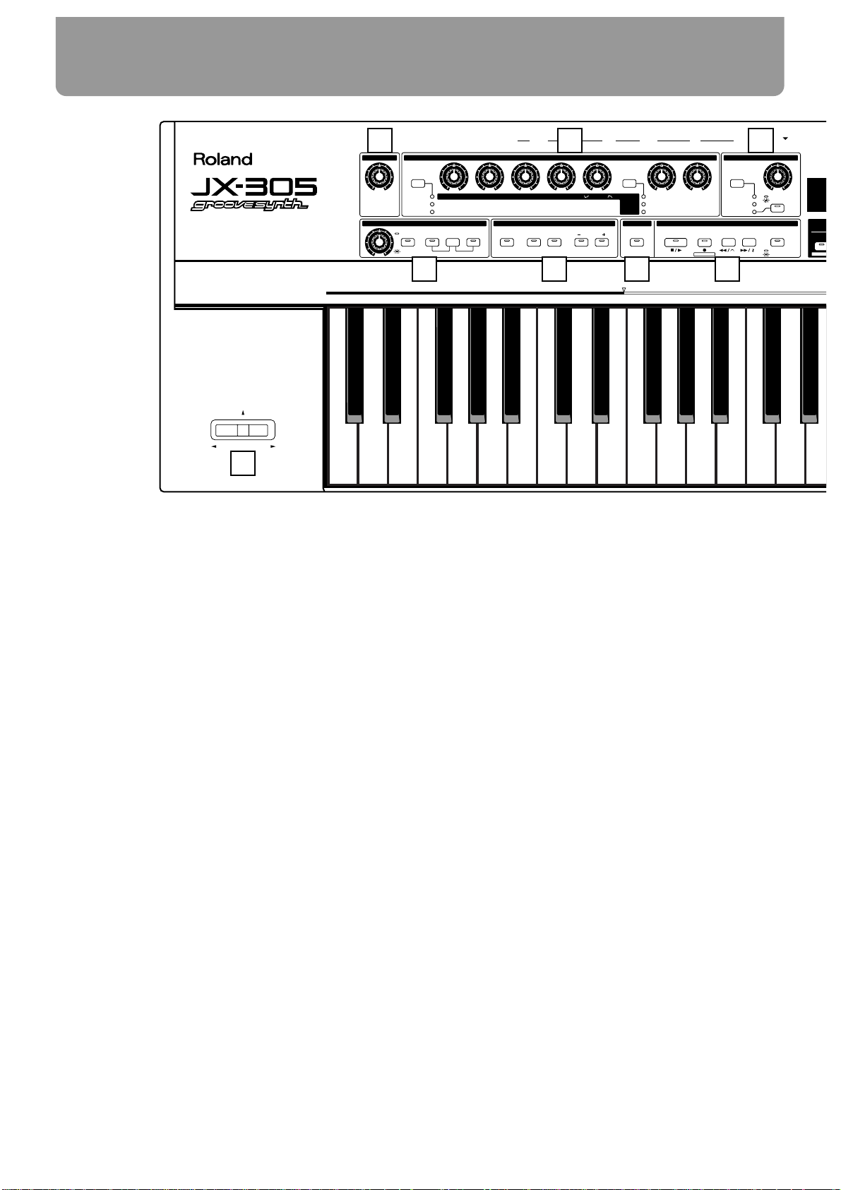
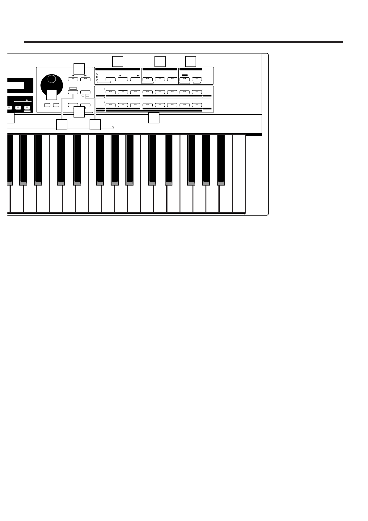
Front Panel
1 VOLUME Knob
Controls the overall volume of the JX-305.
2 REALTIME MODIFY Section
Here you can make settings for sound parameters (p. 54) and effects (p. 101). Also, in the Part
Mixer page you can make various settings for each part (p. 33).
3 QUANTIZE Section
Modifies the groove of the pattern (p. 40).
4 ARPEGGIATOR/RPS Section
Here you can make arpeggiator (p. 24)/RPS settings (p. 48).
5 KEYBOARD Section
Here you can make settings which affect the notes played on the keyboard, such as Key Mode
(p. 18), Octave Shift (p. 21), and Portamento (p. 21).
6 TRANSPOSE Button
Press this button when you wish to transpose (p. 32).
7 SEQUENCER Section
Here are the buttons related to sequencer playback (p. 30) and recording (p. 125).
8 DISPLAY Section
The parameter you wish to modify using [INC] [DEC] or the [VALUE] dial appears in the display.
9 INC/DEC (Increment/Decrement) Buttons
VALUE Dial
Use these to modify the value of a parameter (p. 16).
Front and Rear Panels
10
MODULATION
BENDER
PATTERN
SONG
CUTOFF
LEVEL
PORTA TIME
RESONANCE
PANPOT
FINE TUNE
ENVELOPE
LFO1
MAX
MIN
EFFECTS
STOP/ PL AY
REC
BWD
/TIE
FWD
/REST MODE
OCTAVE
RANGE
RATE
ACCENT
OCTAVEDUALSPLIT
PORTAMENTO
ARP RPSHOLD
RATE
REVERB LEVEL
FADE TIME
DELAY LEVEL
PITCH DEPTH
MULTI CTRL1
FILTER DEPTH
MULTI CTRL2
AMP DEPTH
MULTI CTRL3
GRID
SHUFFLE
GROOVE
TIMING
VELOCITY
1234567
RPS
RPS STOP
PATC
AUDITIO
M.SCOPE
PHONES L(MONO)R HOLD
CONTROL SWITCH
IN OUT
MIDI
MEMORY CARD
THRU
OUTPUT
POWER
PEDAL
QUANTIZEREALTIME MODIFY
KEYBOARD
TRANSPOSE
SEQUENCERARPEGGIATOR/RPS
VOLUME
ATTACK DECAY SUSTAIN RELEASE DEPTH FILTER
AMP
PITCH
DC IN
(9V)
1
4 5 6 7
2 3
18
Page 11
10 PAGE</PAGE> Buttons
Use these buttons to switch between levels of the various setting displays. In pages where
you are assigning a name, these buttons move the cursor.
11 SHIFT Button
This button is used in conjunction with other buttons.
12 UNDO/REDO Button
Press this button to cancel the previous operation (p. 17).
13 ENTER/EXIT Buttons
Use these buttons to execute/cancel an operation, or to exit from a setting page.
14 GROUP Section
Here you can select the group for sounds or patterns (p. 18, 30).
15 PART Section
Press these buttons when you wish to use buttons 1– 8 to select or mute parts (p. 18, 32).
16 EDIT/UTILITY Section
Press these buttons when you wish to edit a sound or pattern, or to store or initialize settings.
17 1–8 Buttons
Use these buttons to select the bank and number of a patch or pattern (p. 18), to select parts or
rhythm groups, or to switch muting on/off (p. 32). When editing, these buttons are used to
select parameters.
18 Pitch Bend Lever/Modulation Lever
This lever lets you modify the pitch or apply vibrato. Depending on the settings, this can also
be used to control specific parameters (p. 22, 47).
11
12345678
12345678
SELECT
PART
MUTE
PART
CTRL
MUTE
NUMBER
PREV NEXT
PRESET
USER
CARD
UTILITY
BANK
1234567R
9 10111213141516
TN /
MEASURE
TEMPO&
SET
RPS
BEAT
MIXER
RHYTHM
PART
BD SD HH CLP CYM
TOM/PERC
HIT OTHERS
WRITE
FX ON/OFF
QTZ SELECT
EDIT/ UTILITY
GROUP PART
TONE SELECT
12341234
TONE SWITCH
EDIT
PTN/SONG
PATCH
TRANSPOSE CHG EVENT QUANTIZE
VIEW FILTER
ERASEINSERTDELETECOPY
AMPLIFIER LFO CONTROL RHY TONEFILTERPITCHWAVECOMMON
ARPEGGIO
CONTROLLER
PART MIDI SEQUENCER SETUP
KEYBOARD
EFFECTSSETUP SYSTEM
PATTERN
DEMO
PAGE
DEC INC ENTEREXIT
UNDO
/REDO
LOWER UPPER
SHIFT
ERASE
VALUE
9
10
13
14 15 16
11 12
Page 12
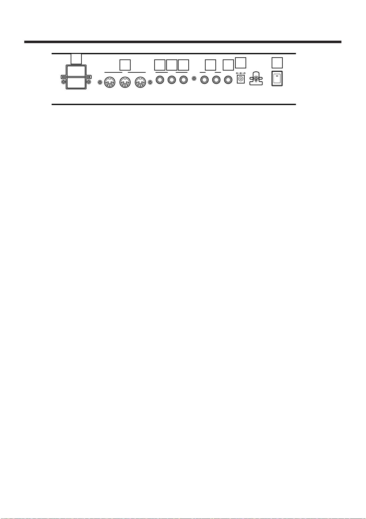
Rear panel
1 MEMORY CARD Slot
An optional memory card (SmartMedia) can be inserted here (p. 159).
2 MIDI IN/OUT/THRU Connectors
External MIDI devices can be connected here (p. 171). Use MIDI cables (sold separately) to
make connections.
3 SWITCH PEDAL Jack
A separately sold pedal switch or foot switch can be connected here. The pedal can be operated to apply various effects (p. 46).
4 CONTROL PEDAL Jack
The expression pedal (EV-5; sold separately) can be connected here. The pedal can be operated to adjust the volume or to make the sound change in various ways (p. 23).
5 HOLD PEDAL Jack
A separately sold pedal switch can be connected here. The pedal can be used to sustain notes
(p. 23).
6 OUTPUT Jacks (L (MONO), R)
An amp or mixer can be connected to these jacks. If outputting in mono, make connections to
the L jack (Quick Start, p. 3).
7 PHONES Jack
Accepts connection of headphones. Audio signals will still be output from the output jacks
even if headphones are connected (Quick Start, p. 3).
8 DC IN Jack
Connect the included AC adapter here (Quick Start, p. 3).
9 POWER Switch
This switch turns the power on/off (Quick Start, p. 5).
12
MEMORY
CARD
S2M-5/S4M-5
THRU
OUT IN
HOLDCONTROL
SWITCH
R
OUTPUT
L(MONO)PHONES
USE ROLAND
ACI,ACB
ADAPTOR ONLY
MIDI PEDAL
450mA
DC IN 9V
POWER
1
2 3 4 5 6 7
98
Page 13
A brief explanation of the JX-305’s internal organization was provided in the Quick Start manual, but this
chapter contains a more detailed explanation of the
basic sections: the controller section, sound generating
section, and the sequencer section.
How the JX-305 Is Organized
fig.1-1TEXT (#MC fig.1-3)
Playing and Operation—Controller
Controllers refer collectively to the keyboard, the
panel knobs, the pitch bend lever, and the pedal connected to the rear panel etc. By operating these controllers you can play sounds or modify them.
Recording Your Performance—
Sequencer
The sequencer can record your playing and controller
operations (knob movements) as MIDI messages, and
can play back the MIDI messages that were recorded.
MIDI messages that have been recorded on the
sequencer can also be transmitted from the MIDI OUT
connector, and used to control external MIDI devices.
Producing the Sound—Sound
Generator
This is the section that produces the sound. The sound
generator produces sound in response to data it
receives from the JX-305’s controllers and its
sequencer. It can also be played by MIDI messages
that arrive from an external MIDI device.
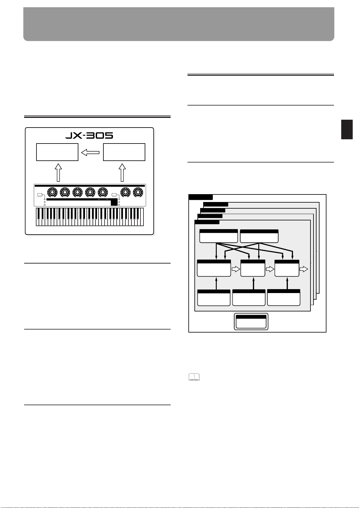
How the Sound Generator Is
Organized
The Smallest Unit of Sound—
Tones
Tones are the smallest unit of sound used by the JX-
305. Although it is possible to create a sound using
only one Tone, the sounds you will normally play on
the JX-305 are “Patches,” which consist of one or more
Tones.
Sounds That You Play—Patches
Patches are the unit of sound that you normally play.
Each Patch consists of up to four Tones.
Tones and Patches are organized as follows.
fig.1-2TEXT (=MC fig.1-4)
* The way in which the four tones are combined will deter-
mine how they will sound. This is determined by the
Structure Type parameter.
☞ “Settings Common to the Entire Patch
(Common)” (p. 77)
Controller section (keyboard, knobs, etc.)
Sound generator
section
Sequencer
section
Playback
Recording
Performance
CUTOFF
LEVEL
PORTA TIME
RESONANCE
PANPOT
FINE TUNE
ENVELOPE
LFO1
EFFECTS
RATE
REVERB LEVEL
FADE TIME
DELAY LEVEL
PITCH DEPTH
MULTI CTRL1
FILTER DEPTH
MULTI CTRL2
AMP DEPTH
MULTI CTRL3
REALTIME MODIFY
ATTACK DECAY SUSTAIN RELEASE DEPTH FILTER
AMP
PITCH
TONE 4
LFO 1
LFO 2
TONE 3
LFO 1
LFO 2
TONE 2
LFO 1
LFO 2
FILTER
AMPLIFIER
TONE 1
PITCH
LFO 1
LFO 2
PITCH ENV
FILTER ENV
AMPLIFIER ENV
WAVE
Cyclically modify the sound
Cyclically modify the sound
Select the basic waveform
Modify the
brightness of
the sound
Modify the volume
Modify the pitch
over time
Modify the brightness
over time
Modify the volume
over time
COMMON
Make common settings
P A TCH
Modify the pitch of the
sound
Chapter 1. an Overview of the JX-305
13
1
Page 14
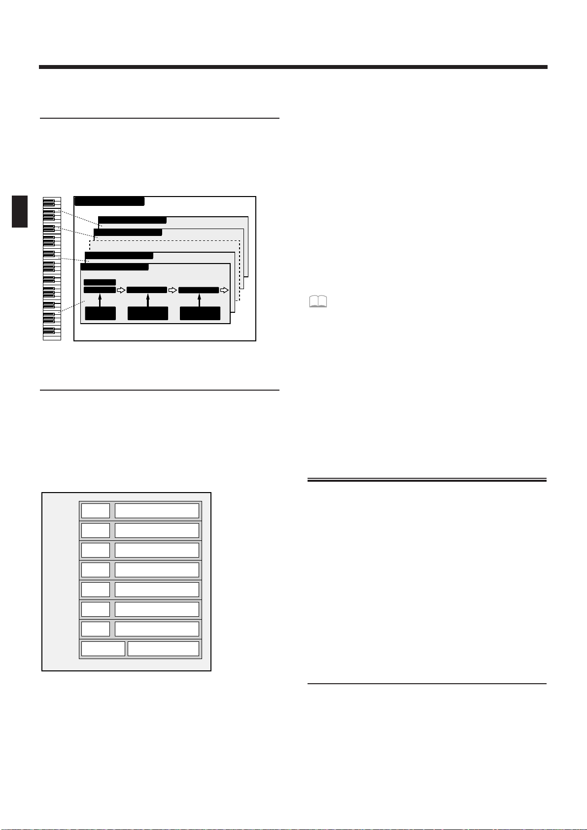
Playing Percussion Instruments—
Rhythm Sets
A collection of various percussion instruments
(rhythm tones) is referred to as a Rhythm Set. A different rhythm tone can be assigned to each key (note
number), allowing you to use a large number of
rhythm tones at once.
fig.1-3 (=MC fig.1-5)
Assigning Instruments to the
Ensemble—Parts
You can think of “Parts” as slots into which Patches
are placed. They can be thought of as being a little like
musicians. You can select a patch (instrument) for each
part (musician), and play multiple parts at once. The
JX-305 has eight parts for pattern playback, and you
can adjust the volume and pan etc. for each part.
fig.1-4TEXT (#MC fig.1-6)
Parts 1–7
For each of these parts, you can select a patch and play
melodic, bass or chordal instruments. Since it is also
possible to select an individual rhythm tone, you can
also use one of these parts as an auxiliary rhythm part.
Rhythm part
For this part, you can select a rhythm set and play percussion instrument sounds.
About simultaneous polyphony
The JX-305 is able to play up to 64 notes simultaneously. If the incoming musical data requests more than 64
notes simultaneously, some notes will drop out. When
using patches with a long release time or when using
RPS, be careful not to exceed the maximum simultaneous polyphony. The number of notes that can be
sounded will actually depend not only on the number
of notes being played, but also on the number of tones
that are used by each patch.
For example, if you are playing a patch that uses four
tones, that patch will take up four times the number of
notes that are played.
If you would like to know about the polyphony
settings...
● The Voice Priority parameter can be set for
each patch to specify how notes will be turned
off when the maximum polyphony is exceeded.
☞ “Settings Common to the Entire Patch
(Common)” (p. 77)
● The Voice Reserve parameter can be set to
specify a minimum number of notes that will
be reserved for each part.
☞ “Specifying the Number of Notes for Each
Part (Voice Reserve)” (p. 169)
How the Sequencer Is Organized
The sequencer records your performance and controller operations as musical data. Playing back the
sequencer will cause this recorded musical data to be
sent to the sound generator, making it produce sound.
In other words, the sequencer plays the instrument
instead of the musician.
In the sense that it records and plays back a performance, a sequencer is similar to a tape recorder.
However, it has unique advantages: the tempo can be
modified without affecting the pitch, there is no
decrease in sound quality no matter how many times
you play something back, and extremely detailed edits
can be made at will.
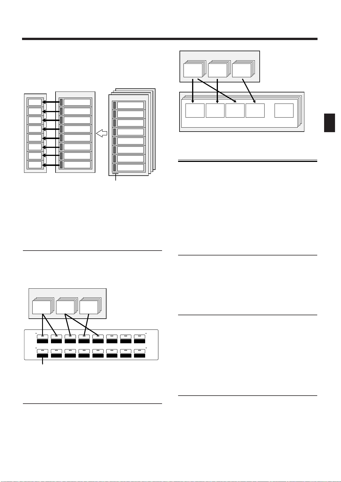
Musical Data Played Back by the
Sequencer—Patterns
Patterns are musical data of various genres for the
sequencer to play back, and can be selected even while
they play back. The data within each pattern is divided into parts, and you can record or play back each
part separately, or modify the musical data inside each
part. For each pattern, you can also specify things such
as the patch, volume and effect settings that will be
used by each part.
RHYTHM TONE (B5)
RHYTHM TONE (D5)
RHYTHM TONE (C4)
FILTER
AMPLIFIER
RHYTHM TONE (B1)
PITCH
WAVE
PITCH
ENV
FILTER
ENV
AMPLIFIER
ENV
RHYTHM SET
Patch
Patch
Patch
Patch
Patch
Patch
Patch
Rhythm Set
Part 1
R Part
Part 2
Part 3
Part 4
Part 5
Part 6
Part 7
Setup parameters
Setup parameters
Setup parameters
Setup parameters
Setup parameters
Setup parameters
Setup parameters
Setup parameters
Sound generator section
Chapter 1. an Overview of the JX-305
14
Page 15
You can save the data in the condition that will be
most appropriate, and change the settings as a whole
simply by changing the pattern. These settings can
also be used when you play the keyboard directly.
fig.1-5TEXT (#MC fig.1-7)
There are two types of patterns: “Preset Patterns”
which are already built into the JX-305, and “User
Patterns” which can contain patterns that you create.
Collecting Frequently Used
Patterns—Pattern Sets
A Pattern Set lets you collect frequently used patterns
so that they can be recalled instantly. Sixteen patterns
can be registered in each pattern set.
fig.1-6TEXT
Arranging Patterns in Playback
Order—Songs
A sequential arrangement of two or more patterns is
called a “song.” When you play back a song, the patterns in the song will play back in succession. A song
can contain up to 50 patterns.
fig.1-7TEXT (#MC fig.1-8)
About Memory
“Memory” refers to the place where patch settings and
musical data for patterns and other things are kept.
The memory of the JX-305 is divided into three areas:
System Memory, User Memory, and Preset Memory.
There is also a “temporary area” within memory, into
which data is placed when you select a patch or pattern, and the data in the temporary area is what you
are actually playing and editing.
Memory for Settings That Affect the
Entire JX-305—System Memory
System Memory contains settings for the system parameters that configure the JX-305. These include parameters that determine the overall operation of the
sound generator or sequencer, and MIDI-related settings.
Rewritable Memory—User Memory
The contents of User Memory can be overwritten, and
are used to store settings or musical data that you create. User Memory stores 256 patches, 200 patterns, 50
songs, 60 RPS sets, and 30 pattern sets.
* At the factory settings, the User Patches and the User
Patterns have the same contents as Preset Memory.
Non-Rewritable Memory—Preset
Memory
The contents of Preset Memory cannot be rewritten.
Preset Memory contains 640 patches and 768 patterns.
PTN P:A11
PTN P:A13
Part 2
Part 1
Part 3
Part 4
Part 5
Part 6
Part 7
R Part
Part 2 data
Part 1 data
Part 3 data
Part 4 data
Part 5 data
Part 6 data
Part 7 data
R Part data
Part 2 data
Part 1 data
Part 3 data
Part 4 data
Part 5 data
Part 6 data
Part 7 data
R Part data
Sound source
section
Parts for pattern
playback
Currently playing
Pattern
playback
Switch
patterns
Parts settings
(Patch selection and
setup parameters)
Sequencer
section
P:A11 U:A11 C:A11
Preset
Registered
pattern
Pattern set example
User Card
12345678
12345678
NUMBER
BANK
1234567R
RHYTHM
PART
BD SD HH CLP CYM
TOM/PERC
HIT OTHERS
P:B14 U:A26 C:A12 U:A12 P:A55 P:A56 C:A14P:A23
U:A14 U:A15 U:A15 P:A85 P:B81 P:B73 U:A11 P:A12
....
1234 50
P:A11
P:A14 U:A17 P:A24 C:A13 P:A35
U:A11 C:A11
PRESET USER CARD
Chapter 1. an Overview of the JX-305
15
1
Page 16
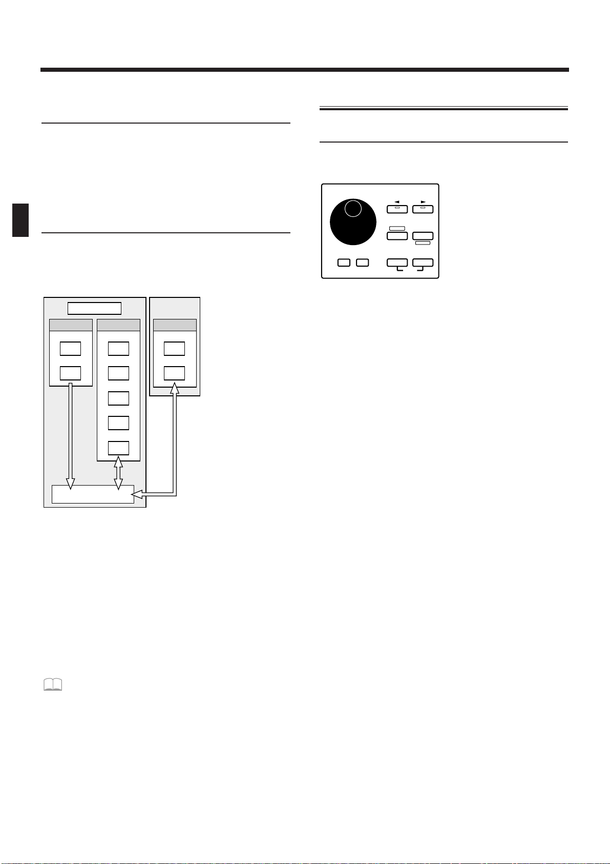
Temporary Memory—The Temporary
Area (Temporary Pattern)
When you play a sound or select a patch for editing,
the selected patch is called into a location known as
the “temporary area.”
When you edit or record a pattern, the contents of the
pattern are automatically copied to TMP (temporary
pattern), and your operations will affect this data.
Memory Card
An optional memory card can be used to store 512
User Patches and 200 User Patterns, just as in the user
memory of the JX-305.
fig.1-8TEXT (#MC fig.1-9)
* The data in memory will be preserved even if the power is
turned off, and can be recalled at any time. However, the
data in the temporary area will be lost when the power is
turned off.
When you modify the settings of a patch or the contents of
a pattern, you are actually modifying the data that was
called into the temporary area or the temporary pattern.
(In other words, you are not directly modifying the data
in memory.) If you wish to keep the changes that you have
made to the patch or pattern, you must save the data as a
user patch or user pattern.
☞ “Saving Patches You’ve Created (Patch
Write)” (p. 82)
☞ “Saving Patterns You’ve Modified (Pattern
Write)” (p. 36)
Basic Operation
Modifying a Value
To select a patch or pattern, or to modify a parameter
value, use the VALUE dial or the INC/DEC buttons.
fig.1-9
INC button/DEC button
To increase a value press [INC]. To decrease a value
press [DEC].
If you continue pressing the button, the value will continue to change.
If you press one button while holding down the other
button, the value will change rapidly.
If you hold down [SHIFT] and press a button, the
value will change in larger steps.
VALUE dial
To increase a value, rotate the [VALUE] dial clockwise. To decrease a value, rotate the [VALUE] dial
counterclockwise.
If you hold down [SHIFT] as you rotate the [VALUE]
dial, the value will change in larger steps.
768
640
200
50
30
60
256
200
512
JX-305
MEMORY CARD
PATCH
PTN
PATCH
PTN
SONG
RPS SET
PATCH
PTN
SYSTEM
PRESET USER CARD
TEMPORARY AREA
PTN SET
DEMO
PAGE
DEC INC ENTEREXIT
UNDO
/REDO
LOWER UPPER
SHIFT
ERASE
VALUE
Chapter 1. an Overview of the JX-305
16
Page 17
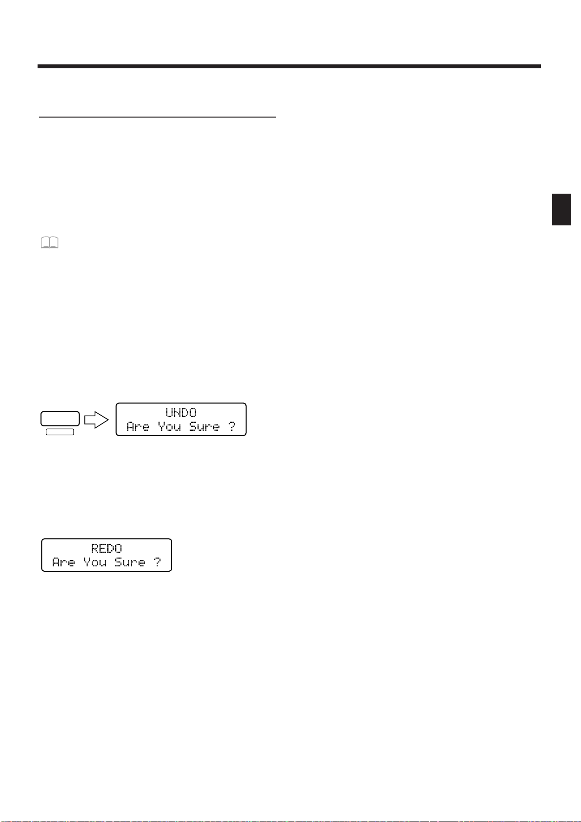
Canceling the Previous
Operation (Undo/Redo)
The function which lets a modified parameter value or
edited musical data to be restored to its previous state
is called Undo. The function which returns the parameter value or musical data from its “Undone” state
back to the edited state is called Redo.
The JX-305 lets you use undo/redo for the following
operations. This is convenient when you wish to cancel a change, or to compare your edits with the original data.
Pattern Edit ☞ “Editing the Musical Data of a
Specified Part (Pattern Edit)” (p. 138)
Song Edit ☞ “Editing Songs (Song Edit)” (p.
155)
Pattern Recording ☞ “Recording Patterns” (p.
125)
Song Recording ☞ “Recording a Song” (p. 155)
1. Make sure that the pattern or song select
page is displayed.
2. Press [UNDO/REDO].
The following display will appear.
fig.1-10 (#MC fig.1-11)
3. Press [ENTER], and your changes will be
“undone,” restoring the value to its
unmodified state.
4. Press [UNDO/REDO] once again.
The following display will appear.
fig.1-11 (#MC fig.1-12)
5.
Press [ENTER], and your changes will be
“redone,” returning the value to its edited state.
* Undo/Redo operations must be done immediately after
you modify the data. Once you save the modified pattern,
the undo/redo operation will no longer be available. Also,
if you use a different operation to make a further change
to the data, it will no longer be possible to undo/redo to
the change that was made first.
When you execute an operation that modifies a large
amount of data, such as during pattern editing, the
Undo operation may not be available.
UNDO
/REDO
ERASE
Chapter 1. an Overview of the JX-305
17
1
Page 18
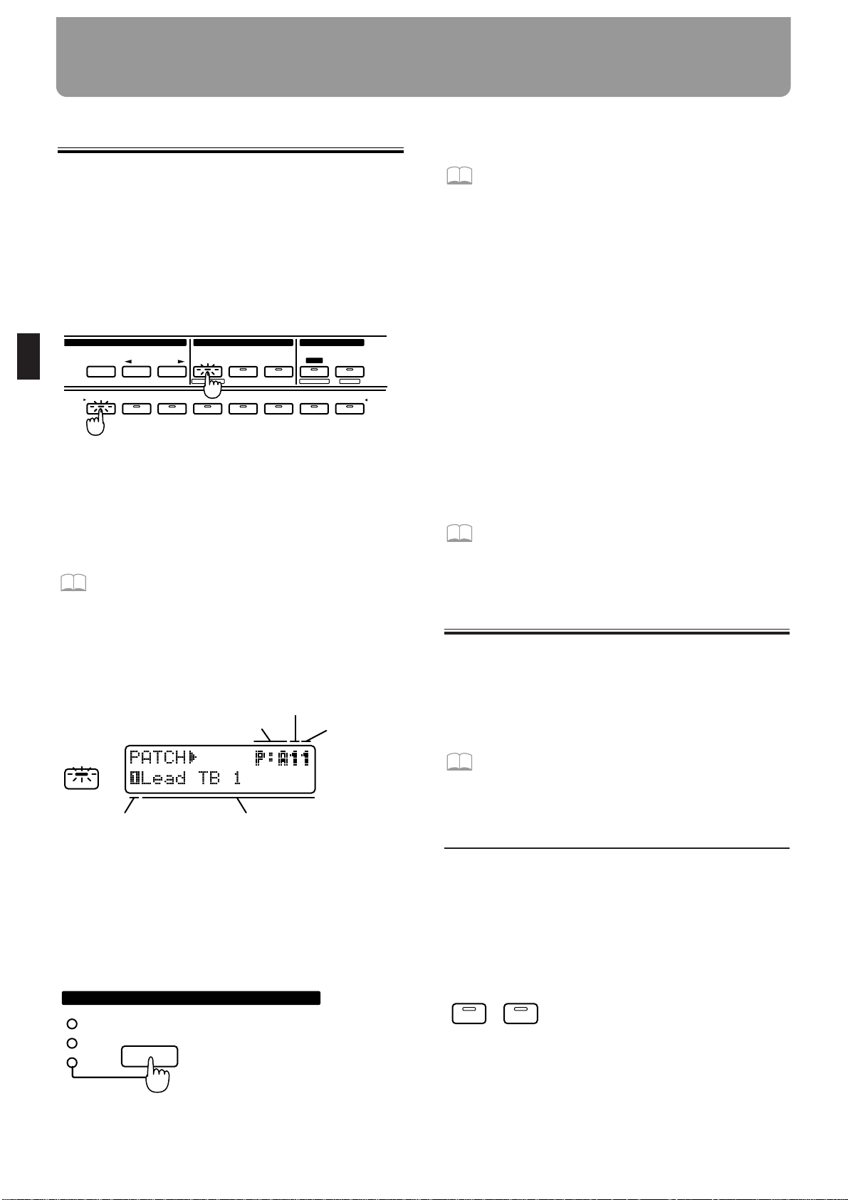
Selecting a Patch
The JX-305 contains a total of 640 different patches.
By specifying the group, bank, and number, you can
select the desired patch and play it on the keyboard.
1. Press [PART SELECT].
The indicator lights.
2. Use PART [1]–[R] to select the part that you
wish to play on the keyboard.
fig.2-1
The currently selected part is referred to as the “current part.”
If the current part is a part 1–7 you can select patches.
If the current part is the rhythm part, you can select
rhythm sets.
☞ “Playing a Rhythm Set” (p. 28)
3. In the DISPLAY section, press [PATCH].
The indicator lights, and the display will show the
group, bank, number and name of the currently selected patch (rhythm set).
fig.2-2E
4. In the GROUP section, press [PRESET/USER/
CARD] to select the group.
Patch groups are organized as follows.
PRESET-> P: A–J (Preset Group)
USER-> U: A–D (User Group)
CARD-> C: A–H (Card Group)
fig.2-3
* The card group cannot be selected unless a separately sold
memory card is inserted.
☞ “Using Memory Cards” (p. 159)
5. In the GROUP section, use [< PREV] [NEXT
>] to select the group (A–J, A–D, A–H).
6. Press [PART SELECT] once again.
The [PART SELECT] indicator goes out, and you can
now use BANK and NUMBER [1]–[8] to select a patch.
7. Use BANK [1]–[8] to select a bank.
8. Use NUMBER [1]–[8] to select a number.
Play the keyboard, and you will hear the selected
patch.
* If the [PART SELECT] or [PART MUTE] indicators in
the PART section are lit, steps 7 and 8 will not be possible. In this case, press [PART SELECT] or [PART
MUTE] to make the indicators go dark.
*Y
ou can also select patches by using [INC] [DEC] or the
[VALUE] dial instead of specifying the group/bank/number.
To view a list of the available patches...
☞ “Preset Patch List” (p. 190)
Playing Two Patches from
the Keyboard (Key Mode)
The JX-305 lets you layer two patches, or play different
patches with the right and left hands. This function is
called the Key Mode.
The Key Mode setting can be stored as part of each
pattern.
☞ “Saving Patterns You’ve Modified (Pattern
Write)” (p. 36)
Playing One Patch Over the
Entire Keyboard (Single)
This is the state in which you will normally play the
keyboard.
1. In the KEYBOARD section, make sure that
the [DUAL] and [SPLIT] indicators are dark.
If either indicator is lit, press the button and get the
indicator to go out.
fig.2-4
12345678
SELECT
PART
MUTE
PART
CTRL
MUTE
PREV NEXT
PRESET
USER
CARD
UTILITY
BANK
1234567R
PART
WRITE
FX ON/ OFF
QTZ SELECT
EDIT/ UTILITY
GROUP PART
EDIT
PATCH
Bank
NumberGroup
Name
Current part
PRESET
USER
CARD
GROUP
DUALSPLIT
Chapter 2. Playing the Keyboard
18
Page 19
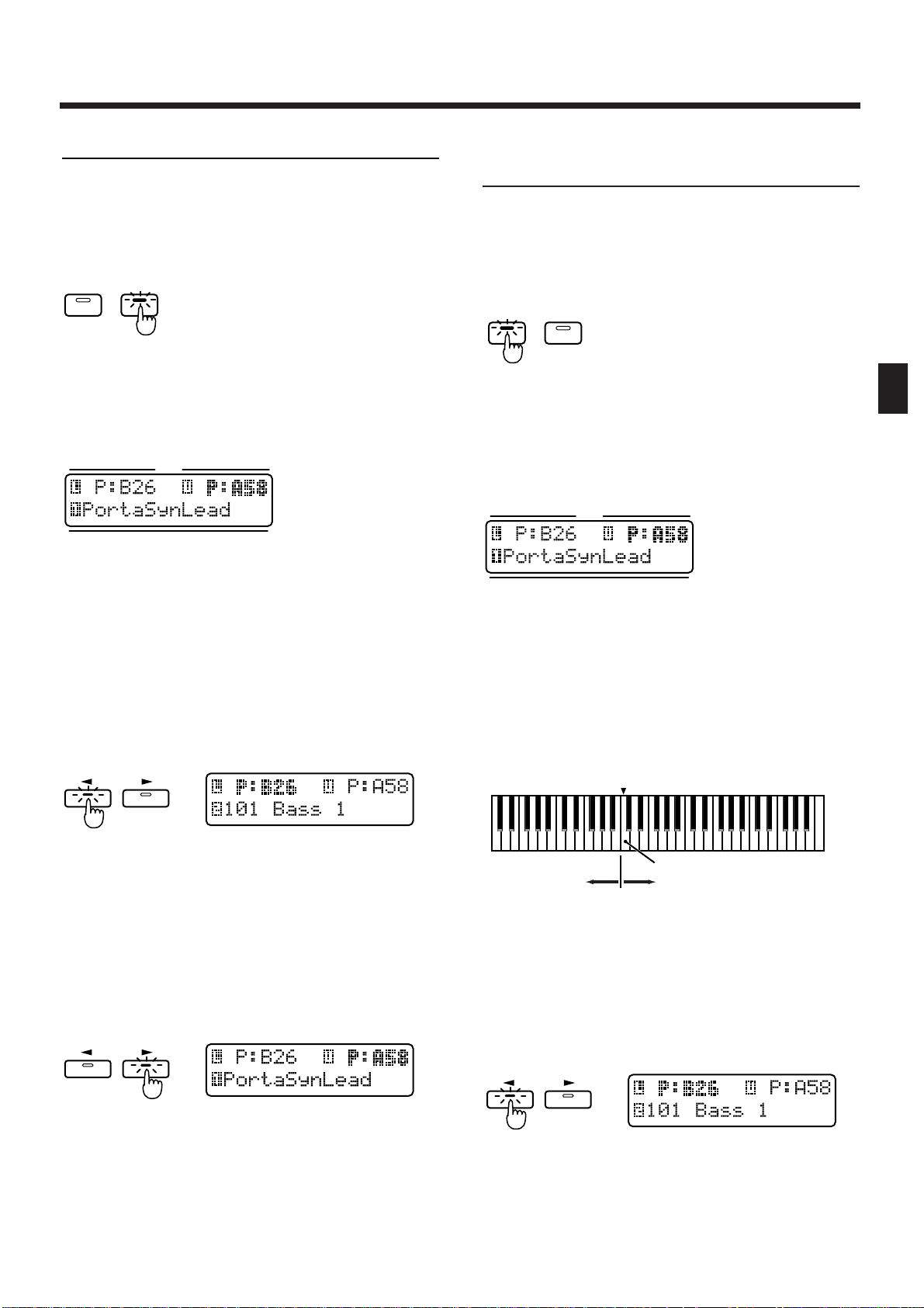
Layering Two Patches (Dual)
1. In the DISPLAY section, press [PATCH].
The indicator lights.
2. In the KEYBOARD section, press [DUAL].
The indicator lights.
fig.2-5
When you select Dual, the following screen will
appear. The part shown in the right of the upper row
is called the “upper part,” and the part shown in the
left of the upper row is called the “lower part.”
fig.2-6
When you play the keyboard, the patches of the lower
part and the upper part will sound simultaneously.
Next, try changing the patch of each part.
3. Press [LOWER].
The indicator lights. The group, bank and number of
the patch for the lower part will be displayed in bold
characters. The lower line of the display will show the
name of the patch that is currently selected for the
lower part.
fig.2-7
4. Select a patch.
The patch of the lower part changes.
5. Press [UPPER].
The indicator lights. The group, bank and number of
the patch for the upper part will be displayed in bold
characters. The lower line of the display will show the
name of the patch that is currently selected for the
upper part.
fig.2-8
6. Select a patch.
The patch of the upper part changes.
7. To return to normal playing condition
(Single), press [DUAL] once again to make
the indicator go dark.
Playing Different Patches with
the Left and Right Hands (Split)
1. In the DISPLAY section, press [PATCH].
The indicator lights.
2. In the KEYBOARD section, press [SPLIT].
The indicator lights.
fig.2-9
When you select Split, the following screen will
appear. The part that is shown in the right of the
upper row is called the “upper part,” and the part that
is shown in the left of the lower row is called the
“lower part.”
fig.2-6
In Split mode, the keyboard is divided into two areas.
Playing the left area will sound the patch of the lower part,
and playing the right area will sound the patch of the upper
part. The note at which the keyboard is devided into left and
right is called the Split Point. For example if the split point is
C4, the keyboard will be divided as shown below. The split
point is included in the Upper part.
fig.2-10TEXT
Here’s how to change the patch of each part:
3. Press [LOWER].
The indicator lights. The group, bank and number of
the patch for the lower part will be displayed in bold
characters. The lower line of the display will show the
name of the patch that is currently selected for the
lower part.
fig.2-7
4. Select a patch.
The patch of the lower part will change.
DUALSPLIT
Patch name
Upper partLower part
PAGE
LOWER UPPER
PAGE
LOWER UPPER
DUALSPLIT
Patch name
Upper partLower part
Lower part Upper part
Split point
C2
C3
C4 C5 C6 C7
PAGE
LOWER UPPER
Chapter 2. Playing the Keyboard
19
2
Page 20
5. Press [UPPER].
The indicator lights. The group, bank and number of
the patch for the upper part will be displayed in bold
characters. The lower line of the display will show the
name of the patch that is currently selected for the
upper part.
fig.2-8
6. Select a patch.
The patch of the upper part will change.
7. To return to normal play mode (Single),
press [SPLIT] once again to make the indicator go dark.
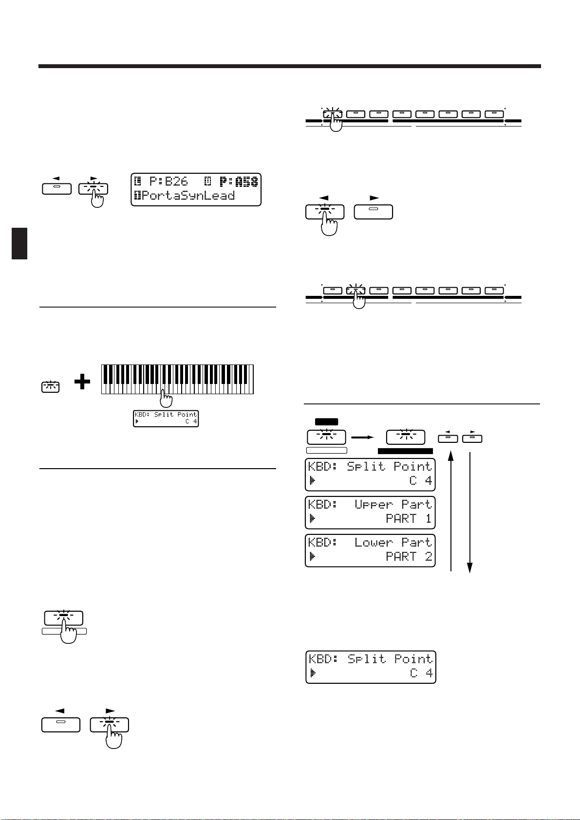
Changing the Split Point
The split point can be changed freely.
1. Hold down [SPLIT] and press the key that
you wish to set as the split point.
fig.2-14
Selecting the Upper Part/Lower Part
Key modes other than Single use two parts (the Upper
part and Lower part). You can select which of the
eight parts will be used as the Upper part, and which
will be used as the Lower part.
* When the Key Mode is Single, the upper part will be
played by the keyboard.
1. Press [PART SELECT].
The indicator lights.
fig.2-15
2. Press [UPPER].
The indicator on the PART button for the part currently selected as the upper part will light.
fig.2-16
3. Press PART [1]–[R] to select the part you
want to assign to the upper part.
fig.2-16-1
4. Press [LOWER].
The indicator on the PART button for the part currently selected as the lower part will light.
fig.2-17
5. Press PART [1]–[R] to select the part you
want to assign to the lower part.
fig.2-17-1
* If you assign the same part to both the upper part and
lower part, it will not be possible to select patches independently.
Modifying the Key Mode
Settings in the Editing Pages
fig.2-13-0
1. Press [EDIT].
The indicator lights, and the Edit page appears.
2. Press BANK [1] (KEYBOARD).
The display will show the Split Point setting page.
fig.2-13
3. Use [INC] [DEC] or the [VALUE] dial to set
the value.
Range: C-1–G9
* The Split Point settings is not affected by Octave Shift.
For example, middle C will be "C4" regardless of the
Octave Shift setting.
PAGE
LOWER UPPER
SPLIT
SELECT
PART
QTZ SELECT
PAGE
LOWER UPPER
12345678
BANK
1234567R
PART
TONE SELECT
12341234
TONE SWITCH
ARPEGGIO
CONTROLLER
PART MIDI SEQUENCER SETUP
KEYBOARD
EFFECTSSETUP SYSTEM
PAGE
LOWER UPPER
12345678
BANK
1234567R
PART
TONE SELECT
12341234
TONE SWITCH
ARPEGGIO
CONTROLLER
PART MIDI SEQUENCER SETUP
KEYBOARD
EFFECTSSETUP SYSTEM
FX ON / OFF
EDIT
1
1
KEYBOARD
PAGE
LOWER UPPER
Chapter 2. Playing the Keyboard
20
Page 21
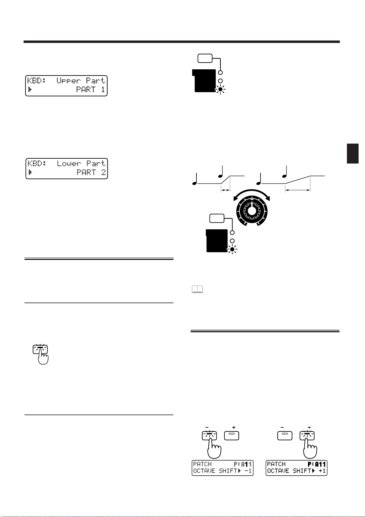
4. Press PAGE [>] to select the upper part setting page.
fig.2-13-1
5. Use [INC] [DEC] or the [VALUE] dial to select
the upper part.
Range: PART 1–7, PART R
6. Once again press PAGE [>] to select the
lower part setting page.
fig.2-13-2
7. Use [INC] [DEC] or the [VALUE] dial to select
the lower part.
Range: PART 1–7, PART R
8. Press [EXIT] to return to the normal display.
Smoothly Changing the Pitch
of the Sound (Portamento)
Portamento is a function which smoothly changes the
pitch from one note to the next. It is effective when
playing single-note lines.
Portamento On/Off
1. In the KEYBOARD section, press [PORTAMENTO].
The indicator lights, and portamento will be turned on.
fig.2-18
2. Each time you press [PORTAMENTO], the
function will be switched on or off.
Changing the Time Over Which the
Pitch Changes (Portamento Time)
You can change the speed at which the pitch will
change when portamento is used.
1. In the REALTIME MODIFY section, press [FILTER/AMP/PITCH] several times, until the
PITCH indicator lights.
fig.2-19
2. Rotate the [PORTA TIME] knob to adjust the
portamento time value.
Range: 0–127
Rotating the knob clockwise will lengthen the time
over which the pitch changes to that of the next note.
Rotating the knob counterclockwise will shorten the
time.
fig.2-20
Portamento settings can be stored as part of the patch.
☞ “Saving Patches You’ve Created (Patch
Write)” (p. 82)
Playing Notes Which Lie Outside the
Range of the Keyboard (Octave Shift)
Octave Shift is a function which shifts the range of the
keyboard in one-octave steps (maximum +/- 3
octaves).
For example, bass notes can be easily played with the
right hand if you first use Octave Shift to lower the
range by one or two octaves.
1. In the KEYBOARD section, press OCTAVE [-]
[+].
The range will be shifted in the -/+ direction, and the
button indicator lights.
fig.2-21
PORTAMENT O
FILTER
AMP
PITCH
CUTOFF
LEVEL
PORTA TIME
FILTER
AMP
PITCH
OCTAVE OCTAVE
Chapter 2. Playing the Keyboard
21
2
Page 22
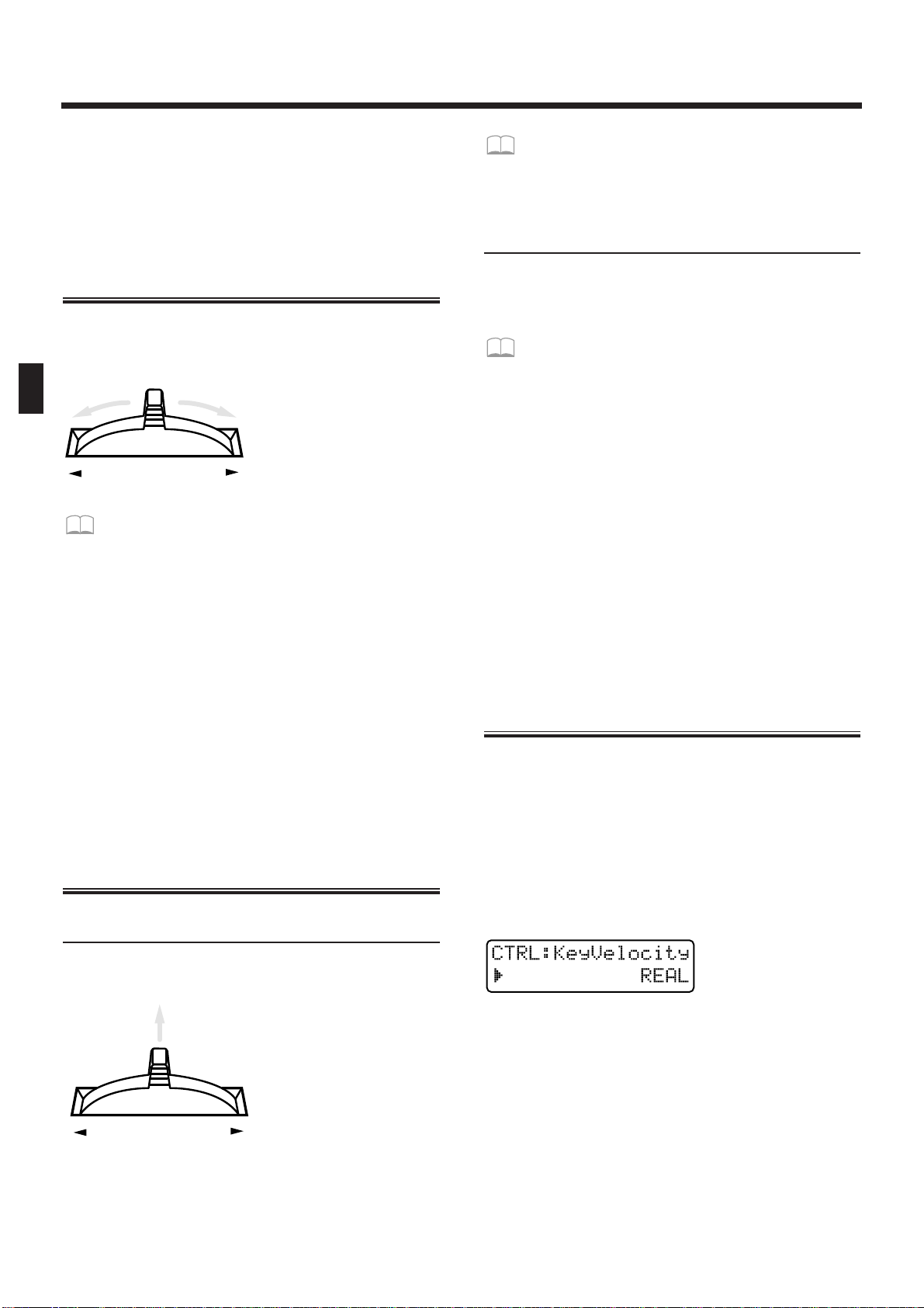
Each time you press OCTAVE [+], the range will be
raised one octave.
Each time you press OCTAVE [-], the range will be
lowered one octave.
While an OCTAVE button is pressed, the display will
indicate the current setting.
Changing the Pitch (Pitch Bend Lever)
By moving the pitch bend lever (located at the left of
the keyboard) to left or right, you can change the pitch
of the sound.
fig.2-22
If you wish to modify the range of pitch
change...
☞ “Adjusting the Range of Pitch Bend (Bend
Range)” (p. 76)
●●●●●●●●●●●●●●●●●●●●●●●●●●●●●●●●●●●●●●●●●●●●●●●●●●●●●●●●●●●●●●●●●●●●●●●●●●●●●●●●●●●●●●●●●●●●●●●●●●●●
Parts affected by the Pitch Bend lever
The part(s) affected by the pitch bend lever will
depend on the Key Mode.
Single : The effect will be applied to the current part.
Split: The effect will be applied to the upper part
when the [UPPER] indicator is lit, and to the
lower part when the [LOWER] indicator is lit.
Dual: Regardless of the [UPPER]-[LOWER] selec-
tion, the effect will be applied to both parts.
●●●●●●●●●●●●●●●●●●●●●●●●●●●●●●●●●●●●●●●●●●●●●●●●●●●●●●●●●●●●●●●●●●●●●●●●●●●●●●●●●●●●●●●●●●●●●●●●●●●●
Applying Modulation to the Sound
Using the Modulation Lever
You can use the Modulation lever to apply changes to
the sound.
fig.2-26
Since the sound will change only when the modulation lever is tilted away from you, this can be used to
add accents to your playing.
If you wish to specify the parameter affected by
the modulation lever...
☞ “Specifying the Parameters That Will Be
Modified by Each Controller (Control)” (p. 76)
Using Aftertouch
Pressure which is applied to the keyboard after playing a note is referred to as "aftertouch." Aftertouch can
be used to apply change to the sound.
To specify the parameter that will be affected
when aftertouch is applied...
☞ “Specifying the Parameters That Will Be
Modified by Each Controller (Control)” (p. 76)
●●●●●●●●●●●●●●●●●●●●●●●●●●●●●●●●●●●●●●●●●●●●●●●●●●●●●●●●●●●●●●●●●●●●●●●●●●●●●●●●●●●●●●●●●●●●●●●●●●●●
Parts that will be affected
The part(s) affected by the modulation lever or aftertouch will depend on the Key Mode.
Single: The effect will be applied to the current part.
Split: The effect will be applied to the upper part
when the [UPPER] indicator is lit, and to the
lower part when the [LOWER] indicator is lit.
Dual: Regardless of the [UPPER]-[LOWER] selec-
tion, the effect will be applied to both parts.
●●●●●●●●●●●●●●●●●●●●●●●●●●●●●●●●●●●●●●●●●●●●●●●●●●●●●●●●●●●●●●●●●●●●●●●●●●●●●●●●●●●●●●●●●●●●●●●●●●●●
Changing the Keyboard
Dynamics (Keyboard Velocity)
The force with which you play the keyboard is called
“velocity.” Velocity can be used to affect the volume
or the way in which each note sounds.
1. Press [EDIT].
The indicator lights, and the edit page will appear in
the display.
2. Press BANK [5] (CONTROLLER).
The Velocity setting page will appear.
fig.2-41
3. Use [INC] [DEC] or the [VALUE] dial to set
the value.
Range:
REAL:
The velocity value will correspond to the strength
with which you actually play the note.
1–127: A fixed velocity value will be produced,
regardless of how strongly you play.
BENDER
BENDER
Chapter 2. Playing the Keyboard
22
Page 23
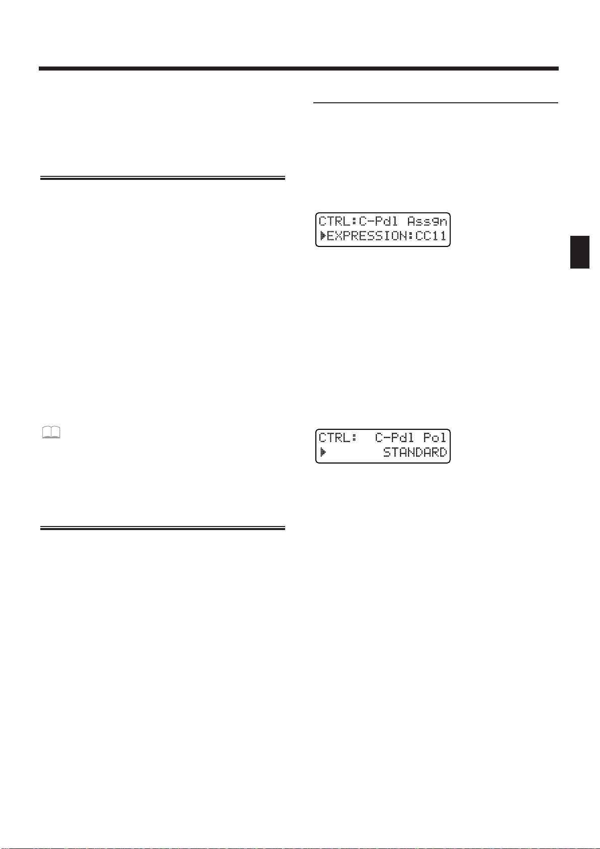
4.
Press [EXIT] when finished making the setting.
The original display will reappear.
The keyboard velocity setting has now been made.
Sustaining the Notes You
Play (Hold Pedal)
When a pedal switch is connected to the Hold Pedal
jack, notes can be sustained while you continue pressing the pedal. Newly played notes will be layered onto
the currently sounding notes. This is the same function
as the damper pedal of a piano.
●●●●●●●●●●●●●●●●●●●●●●●●●●●●●●●●●●●●●●●●●●●●●●●●●●●●●●●●●●●●●●●●●●●●●●●●●●●●●●●●●●●●●●●●●●●●●●●●●●●●
Parts that will be held
The part(s) that will be held will depend on the Key
Mode.
Single: The current part will be held.
Split: The upper part will be held when the
[UPPER] indicator is lit, and the lower part
will be held when the [LOWER] indicator is
lit.
Dual: Both parts will be held, regardless of the
[UPPER]-[LOWER] selection.
●●●●●●●●●●●●●●●●●●●●●●●●●●●●●●●●●●●●●●●●●●●●●●●●●●●●●●●●●●●●●●●●●●●●●●●●●●●●●●●●●●●●●●●●●●●●●●●●●●●●
If you wish to know about the Hold Pedal setting...
☞ “Specifying How the Pedal Will Function”
(p. 163)
Using a Pedal to Modify the
Sound (Control Pedal)
If you connect an expression pedal to the control pedal
jack, you can use the pedal to modify the volume and
tonal character of the sound.
●●●●●●●●●●●●●●●●●●●●●●●●●●●●●●●●●●●●●●●●●●●●●●●●●●●●●●●●●●●●●●●●●●●●●●●●●●●●●●●●●●●●●●●●●●●●●●●●●●●●
Parts that will be controlled
The part(s) that will be controlled by the Control pedal
will depend on the Key Mode.
Single: The sound of the current part will be con-
trolled.
Split: The upper part will be controlled when the
[UPPER] indicator is lit, and the lower part
when the [LOWER] indicator is lit.
Dual: Regardless of the [UPPER]-[LOWER] selec-
tion, the effect will be applied to both parts.
●●●●●●●●●●●●●●●●●●●●●●●●●●●●●●●●●●●●●●●●●●●●●●●●●●●●●●●●●●●●●●●●●●●●●●●●●●●●●●●●●●●●●●●●●●●●●●●●●●●●
Control Pedal Settings
1. Press [EDIT].
The indicator lights, and the editing page will appear.
2. Press BANK [5] (CONTROLLER).
The CONTROLLER setting page will appear.
3. Press PAGE [<] [>] several times to select
the Control Pedal Assign page.
fig.2-38
4. Use [INC] [DEC] or the [VALUE] dial to specify the MIDI message that will be transmitted when the pedal is pressed.
Range:
CC 01–95: Controller numbers 1–95
(except for 6, 32, 38)
PITCH BEND UP: Pitch Bend Up
PITCH BEND DOWN: Pitch Bend Down
AFTERTOUCH: Aftertouch
5. Once again press PAGE [>] to select the
Control Pedal Polarity page.
fig.2-40
6. Use [INC] [DEC] or the [VALUE] dial to set
the value.
Range: STANDARD, REVERSE
If you are using a pedal whose polarity is inverted
(i.e., when the pedal operation is opposite that of what
you expect), select “REVERSE.”
7. Press [EXIT] to complete the setting.
The original display will reappear.
Chapter 2. Playing the Keyboard
23
2
Page 24
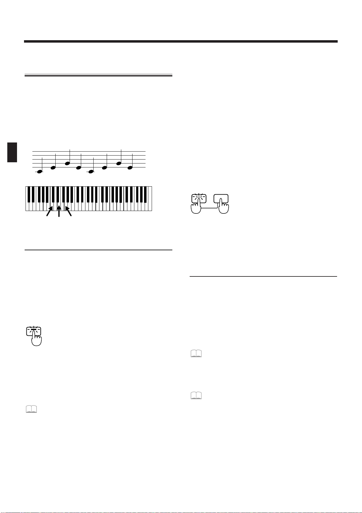
Pressing Chords to Produce
Arpeggios (Arpeggiator)
By using the arpeggiator, you can produce an arpeggio (broken chord) simply by holding down the chord.
For example, if you hold down a C major chord as fol-
lows, an arpeggio of C3, E3, G3, E3, C3, E3, G3.... will
be played.
In the case of
Arpeggio Style: 1/4
Octave Range: 0
fig.2-42(=MC fig.5-1)
Playing Arpeggios
1. Use [PART SELECT] and PART [1]–[R] to
select the part to be used to play arpeggios.
2. In the ARPEGGIATOR/RPS section, press
[ARP].
The indicator lights, and the arpeggiator will be
turned on.
fig.2-43
3. When you play the keyboard, any chord
you play will be sounded as an arpeggio.
* The tempo of the arpeggio will be synchronized to the
tempo of the pattern. If you wish to change the speed of
the arpeggio, change the tempo of the pattern.
☞ “Adjusting the Tempo” (p. 31)
●●●●●●●●●●●●●●●●●●●●●●●●●●●●●●●●●●●●●●●●●●●●●●●●●●●●●●●●●●●●●●●●●●●●●●●●●●●●●●●●●●●●●●●●●●●●●●●●●●●●
Parts that can be used for arpeggios
The part(s) that will sound the arpeggio will depend
on the Key Mode.
Single: Arpeggios can be played on the current part.
Split: Regardless of the [UPPER]-[LOWER] selec-
tion, arpeggios can be played only on the
lower part.
Dual: Arpeggios can be played on either the upper
or the lower, or on both the upper and lower.
For details refer to “Selecting the Part in Dual
Mode Which Will Play the Arpeggio
(Arpeggio Destination)” (p. 26)
●●●●●●●●●●●●●●●●●●●●●●●●●●●●●●●●●●●●●●●●●●●●●●●●●●●●●●●●●●●●●●●●●●●●●●●●●●●●●●●●●●●●●●●●●●●●●●●●●●●●
●●●●●●●●●●●●●●●●●●●●●●●●●●●●●●●●●●●●●●●●●●●●●●●●●●●●●●●●●●●●●●●●●●●●●●●●●●●●●●●●●●●●●●●●●●●●●●●●●●●●
Arpeggio Hold
If you hold down [HOLD] and press [ARP], and get
the indicator to start blinking, the arpeggio will continue sounding even after you take your fingers off the
keyboard. If you play a different chord or notes while
the arpeggio is being held, the arpeggio will change
accordingly.
To cancel Arpeggio Hold, hold down [HOLD] and
press [ARP] simultaneously once again.
fig.2-44
Also, if you connect a pedal switch (sold separately) to
the Hold Pedal jack, you can hold the arpeggio as long
as the pedal switch is pressed.
●●●●●●●●●●●●●●●●●●●●●●●●●●●●●●●●●●●●●●●●●●●●●●●●●●●●●●●●●●●●●●●●●●●●●●●●●●●●●●●●●●●●●●●●●●●●●●●●●●●●
Creating an Arpeggio Pattern
When you wish to make arpeggiator settings, you will
first select an Arpeggio Style. When you select a style,
optimal values will be set for the four parameters
“Accent Rate,” “Motif,” “Beat Pattern,” and “Shuffle
Rate.” You can adjust parameters such as Accent Rate
and Octave Range to modify the pattern to your taste.
If this is not enough, you can also make more detailed
settings.
☞ “Making More Detailed Settings” (p. 26)
The arpeggiator settings you modify can be stored as a
User Style.
☞ “Saving Arpeggio Settings (Arpeggio Write)”
(p. 28)
C3
E3 E3G3
C3
E3 E3G3
C3 E3 G3
ARP
ARP HOLD
Chapter 2. Playing the Keyboard
24
Page 25
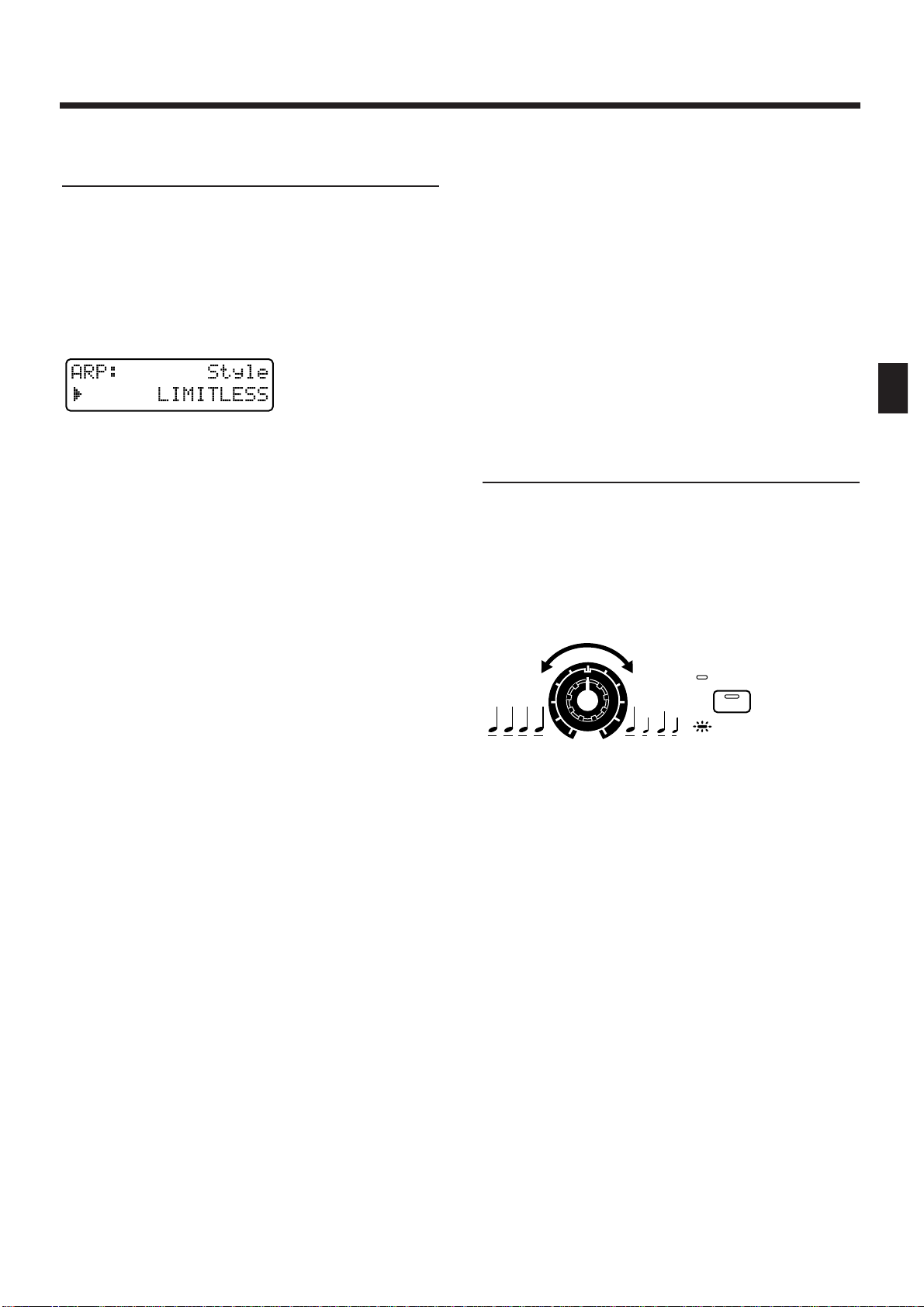
Changing the Way in Which the
Arpeggio Will Play (Arpeggio Style)
Specifies the basic way in which the arpeggio will be
played. Select one of the following 53 types.
1. Hold down [ARP] in the ARPEGGIATOR/RPS
section, and use [INC] [DEC] or the [VALUE]
dial to select the style.
While you hold down the button, the display will indicate the currently-selected style.
fig.2-45(#MC fig.5-4)
Available Settings:
1/4: The rhythm will be divided in quarter notes.
1/6: The rhythm will be divided in quarter note
triplets.
1/8: The rhythm will be divided in eighth notes.
1/12: The rhythm will be divided in eighth note
triplets.
1/16: The rhythm will be divided in 16th notes.
1/32: The rhythm will be divided in 32nd notes.
PORTAMENTO A, B: A style using the portamento
effect.
GLISSANDO: A glissando style.
SEQUENCE A–D: Styles for sequenced patterns.
ECHO: An echo-like style.
SYNTH BASS, HEAVY SLAP, LIGHT SLAP, WALK
BASS: Styles appropriate for bass playing.
RHYTHM GTR 1–5: Styles for guitar cutting. Styles
2–5 are effective when 3–4 notes are held.
3 FINGER: Three-finger guitar style.
STRUMMING GTR: A style simulating a guitar
chord strummed upward (downward). Effective when
5–6 notes are held.
PIANO BACKING, CLAVI CHORD: Styles for keyboard instrument backing.
WALTZ, SWING WALTZ: Styles in triple meter.
REGGAE: A reggae-type style. Effective when 3 notes
are held.
PERCUSSION: A style suitable for percussive instrument sounds.
HARP: The playing style of a harp.
SHAMISEN: The playing style of a Shamisen.
BOUND BALL: A style suggestive of a bouncing ball.
RANDOM: A style in which the notes sound in ran-
dom order.
BOSSANOVA: A style with bossanova guitar cutting.
Hold 3–4 notes for best results. You can increase the
BPM and use this as a Samba.
SALSA:Typical salsa style. Hold 3–4 notes for best
results.
MAMBO: Typical mambo style. Hold 3–4 notes for
best results.
LATIN PERCUSION: A rhythm style with Latin percussion instruments such as Clave, Cowbell, Clap,
Bongo, Conga, Agogo etc.
SAMBA: Typical samba style. Use for rhythm patterns
or bass lines.
TANGO: Typical tango rhythm style. Hold the root,
3rd and 5th of a triad etc. for best results.
HOUSE: A style for house piano backing. Hold 3–4
notes for best results.
LIMITLESS: The settings of all parameters can be
freely combined without restriction.
USER STYLE 1–10: Arpeggio settings can be modified
and saved in one of these user styles.
Adding Expression to the
Arpeggio (Accent Rate)
By modifying the accent strength and note length, you
can change the sense of groove of the arpeggio.
1. Press [ACCENT RATE/OCTAVE RANGE] to
make the indicator go dark.
2. Rotate the [ACCENT RATE] knob to set the
accent rate.
fig.2-46
Rotating the knob clockwise will strengthen the sense
of groove. Rotating the knob counterclockwise will
decrease the amount of expression.
OCTAVE
RANGE
RATE
ACCENT
Chapter 2. Playing the Keyboard
25
2
Page 26
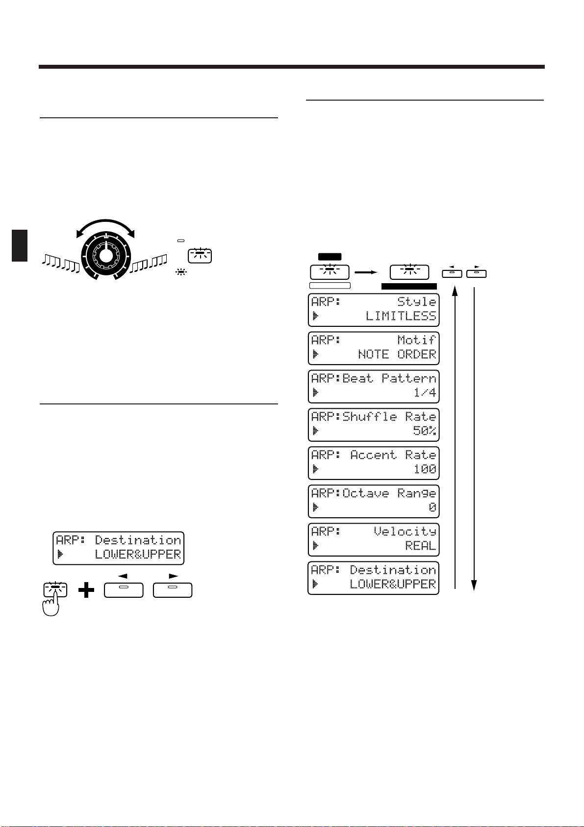
Changing the Pitch Range of the
Arpeggio (Octave Range)
You can specify the pitch range in which the arpeggio
will be developed, in steps of one octave.
1. Press [ACCENT RATE/OCTAVE RANGE] to
make the button indicator light.
2. Rotate the [OCTAVE RANGE] knob to set the
Octave Range.
fig.2-47
Rotating the knob clockwise will cause the pitch range
to be extended upward from the notes which you
play. Rotating the knob counterclockwise will extend
the pitch range downward.
Selecting the Part in Dual Mode
Which Will Play the Arpeggio
(Arpeggio Destination)
When the Key Mode is set to Dual, this setting specifies whether the upper and/or lower part will play
arpeggios.
1. Make sure that the [ARP] indicator is lit.
2. Hold down [DUAL] and use [LOWER]
[UPPER] to select the destination part.
If you press [LOWER] [UPPER] simultaneously, the
destination part will be "LOWER&UPPER."
fig.2-48-0
Range:
LOWER&UPPER: The patches of the upper and
lower parts will be layered to
sound the arpeggio.
LOWER: Arpeggios will be played only on
the lower part. For example, this
lets you play chords in the upper
part and arpeggios in the lower
part.
UPPER: Arpeggios will be played only on
the upper part.
Making More Detailed Settings
Normally you will create the arpeggio pattern by
adjusting the three parameters “Arpeggio Style,”
“Accent Rate,” and “Octave Range.” However by
modifying the settings of additional parameters, you
can create arpeggio patterns that are even richer in
variation.
1. Press [EDIT].
The indicator lights, and the edit page appears.
2. Press BANK [4] (ARPEGGIO).
The ARPEGGIO setting page will appear.
fig.2-48(#MC fig.5-7)
3. Use PAGE [<] [>] to select the parameter
page, and set the parameters.
To leave the setting page, press [EXIT].
OCTAVE
RANGE
RATE
ACCENT
DUAL
PAGE
LOWER UPPER
FX ON / OFF
EDIT
4
4
ARPEGGIO
PAGE
LOWER UPPER
Chapter 2. Playing the Keyboard
26
Page 27

Style (Arpeggio Style)
This is the setting page for “Changing the Way in
Which the Arpeggio Will Play (Arpeggio Style)” (p.
25).
Motif
Specifies the order in which the notes of the chord will
be sounded.
Available Settings:
SINGLE UP: Notes you press will be sounded indi-
vidually, beginning from low to high.
SINGLE DOWN: Notes you press will be sounded
individually, from high to low.
SINGLE UP&DOWN: Notes you press will be sounded individually, from low to high, and then back
down from high to low.
SINGLE RANDOM: Notes you press will be sounded
individually, in random order.
DUAL UP: Notes you press will be sounded two at a
time, beginning from low to high.
DUAL DOWN: Notes you press will be sounded two
at a time, beginning from high to low.
DUAL UP&DOWN: Notes you press will be sounded
two at a time, from low to high, and then back down
from high to low.
DUAL RANDOM: Notes you press will be sounded
two at a time, in random order.
TRIPLE UP: Notes you press will sound three at a
time, from low to high.
TRIPLE DOWN: Notes you press will sound three at
a time, from high to low.
TRIPLE UP&DOWN: Notes you press will sound
three at a time, from low to high and then back down
from high to low.
TRIPLE RANDOM: Notes you press will sound three
at a time, in random order.
NOTE ORDER: Notes you press will be sounded in
the order in which you pressed them. By pressing the
notes in the appropriate order you can produce
melody lines. Up to 128 notes will be remembered.
GLISSANDO: Each chromatic step between the highest and lowest notes you press will sound in succession, repeating upward and downward. Press only the
lowest and the highest notes.
CHORD: All notes you press will sound simultaneously.
BASS+CHORD 1–5: The lowest of the notes you play
will sound, and the remaining notes will sound as a
chord.
BASS+UP 1–8: The lowest of the notes you play will
sound, and the remaining notes will be arpeggiated.
BASS+RND 1–3: The lowest of the notes you play will
sound, and the remaining notes will sound in random
order.
TOP+UP 1–6: The highest of the notes you play will
sound, and the remaining notes will be arpeggiated.
BASS+UP+TOP: The highest and the lowest of the
notes you play will sound, and the remaining notes
will be arpeggiated.
* The parameters which can be set will depend on the cur-
rently-selected Arpeggio Style.
Beat Pattern
This allows you to select the Beat Pattern. It will affect
the accent location and note length, causing the beat
(rhythm) to change.
Range : 1/4, 1/6, 1/8, 1/12, 1/16 1–3, 1/32 1–3, PORTA-A
1–11, PORTA-B 1–15, SEQ-A 1–7, SEQ-B 1–5,
SEQ-C 1, 2, SEQ-D 1–8, ECHO 1–3, MUTE
1–16, STRUM 1–8, REGGAE 1, 2, REF 1, 2,
PERC 1–4, WALKBS, HARP, BOUND, RANDOM, BOSSA NOVA, SALSA 1–4, MAMBO
1–2, CLAVE, REV CLA, GUILO, AGOGO,
SAMBA, TANGO 1–4, HOUSE 1, 2
●●●●●●●●●●●●●●●●●●●●●●●●●●●●●●●●●●●●●●●●●●●●●●●●●●●●●●●●●●●●●●●●●●●●●●●●●●●●●●●●●●●●●●●●●●●●●●●●●●●●
If “PORTA-A 1–11, PORTA-B 1–15” is selected as the
Beat Pattern, the Patch parameter Portamento Time (p.
78) will control the speed of portamento. Adjust the
portamento time as appropriate for the playback
tempo. (It is not necessary to turn portamento on.)
●●●●●●●●●●●●●●●●●●●●●●●●●●●●●●●●●●●●●●●●●●●●●●●●●●●●●●●●●●●●●●●●●●●●●●●●●●●●●●●●●●●●●●●●●●●●●●●●●●●●
* The parameters which can be set will depend on the cur-
rently-selected Arpeggio Style.
Shuffle Rate
This setting lets you modify the note timing to create
shuffle rhythms.
Range: 50–90 (%)
With a setting of 50%, the notes will sound at equal
spacing. As this value is increased, the notes will
become more “bouncy,” as if they were dotted notes.
fig.2-49(=MC fig.5-8)
* If the Beat Pattern setting is “1/4,” shuffle will not be
applied even if you increase the Shuffle Rate setting.
Accent Rate
This is the setting page for “Adding Expression to the
Arpeggio (Accent Rate)” (p. 25).
Range: 0–100
90 10 90 10
50 50 50 50
Shuffle Rate = 50%
Shuffle Rate =90%
Chapter 2. Playing the Keyboard
27
2
Page 28
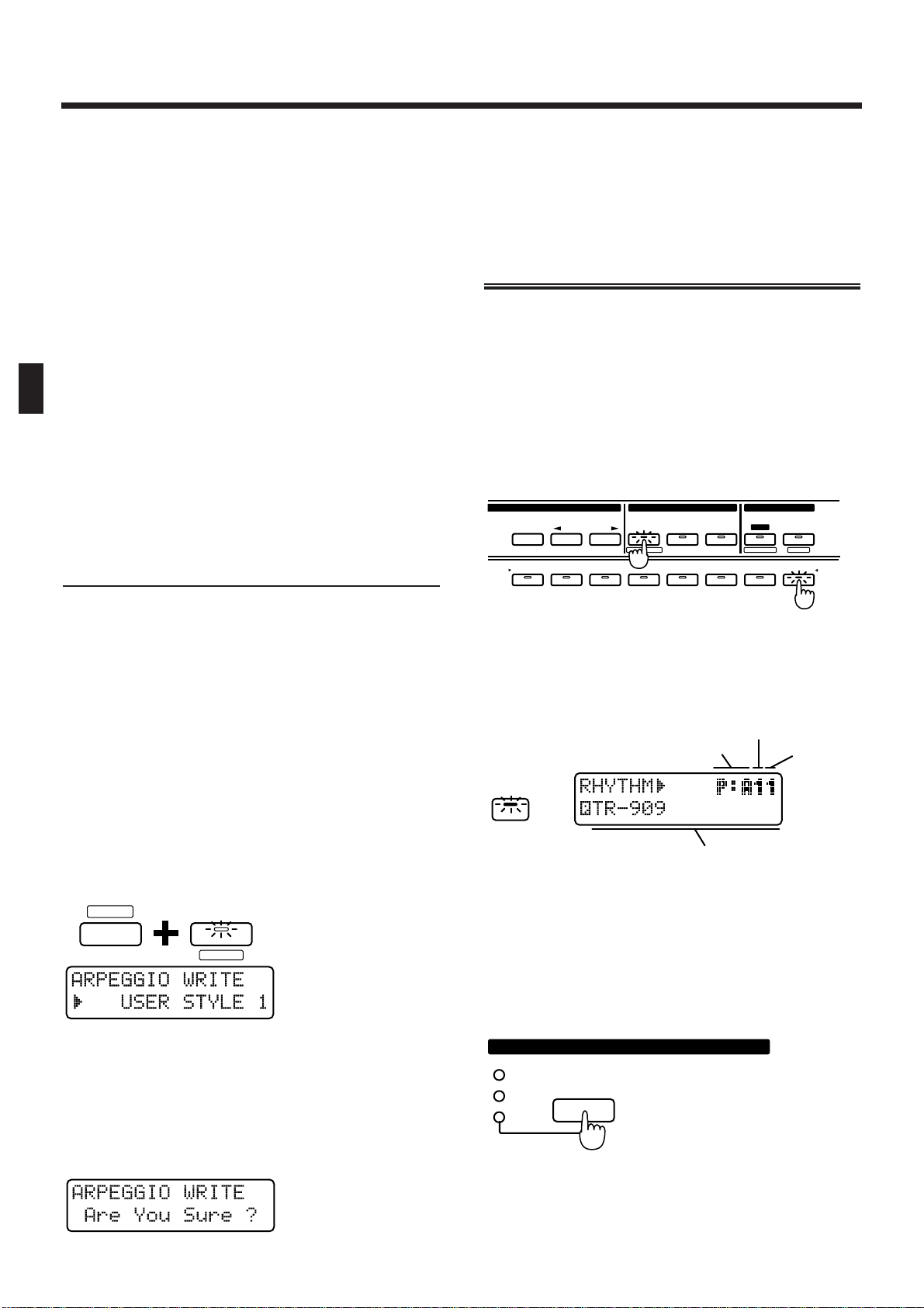
Octave Range
This is the setting page for “Changing the Pitch Range
of the Arpeggio (Octave Range)” (p. 26).
Range: -3–+3
Velocity
Specify the loudness of the notes that you play.
Range: REAL, 1–127
If you want the velocity value to change according to
how strongly you played each note, set this to REAL.
If you want to produce a constant velocity value
regardless of how strongly each note was played,
specify the desired value.
Destination
This is the setting page for “Selecting the Part in Dual
Mode Which Will Play the Arpeggio (Arpeggio
Destination)” (p. 26).
Saving Arpeggio Settings
(Arpeggio Write)
When you have created a playback pattern that you
like, save the settings as a User Style. The JX-305 has
ten user styles, USER STYLE 1–10, and user styles that
you save can be recalled at any time.
* Velocity and Destination Part cannot be saved.
1. Create an arpeggio playback pattern.
2. Make sure that the ARPEGGIO setting page
is shown in the display.
If it is not displayed, press [EDIT] and then press
BANK [4] to access the setting page.
3. Hold down [SHIFT] and press [WRITE].
The indicator will blink, and the following display will
appear.
fig.2-50
4. Use [INC] [DEC] or the [VALUE] dial to specify the writing destination user style.
Range: USER STYLE 1–10
5. Press [ENTER].
The execute page will appear in the display.
fig.2-51
6. Press [ENTER] once again.
The Arpeggio Write operation will be executed, and
the normal display will reappear.
To cancel the operation without executing, press
[EXIT].
Playing a Rhythm Set
The JX-305 contains various rhythm sets, each of
which have a different percussion instrument sound
or sound effect assigned to each key.
These rhythm sets can be selected by specifying the
group, bank and number, and are played from the
keyboard.
1. Use [PART SELECT] and PART [R] to select
the rhythm part.
fig.2-52
2. In the DISPLAY section, press [PATCH].
The indicator lights, and the display will show the
group, bank, number and name of the currently selected rhythm set.
fig.2-53E
3. In the GROUP section, press [PRESET/USER/
CARD] to select the group.
Rhythm set groups are organized as follows:
PRESET
→ P: A, B (Preset group)
USER → U: (User group)
CARD → C: (Card group)
fig.2-3
* The Card group can be selected only when an optional
memory card is inserted.
SHIFT
UTILITY
WRITE
12345678
SELECT
PART
MUTE
PART
CTRL
MUTE
PREV NEXT
PRESET
USER
CARD
UTILITY
BANK
1234567R
PART
WRITE
FX ON/ OFF
QTZ SELECT
EDIT/ UTILITY
GROUP PART
EDIT
PATCH
Bank
NumberGroup
Name
PRESET
USER
CARD
GROUP
Chapter 2. Playing the Keyboard
28
Page 29
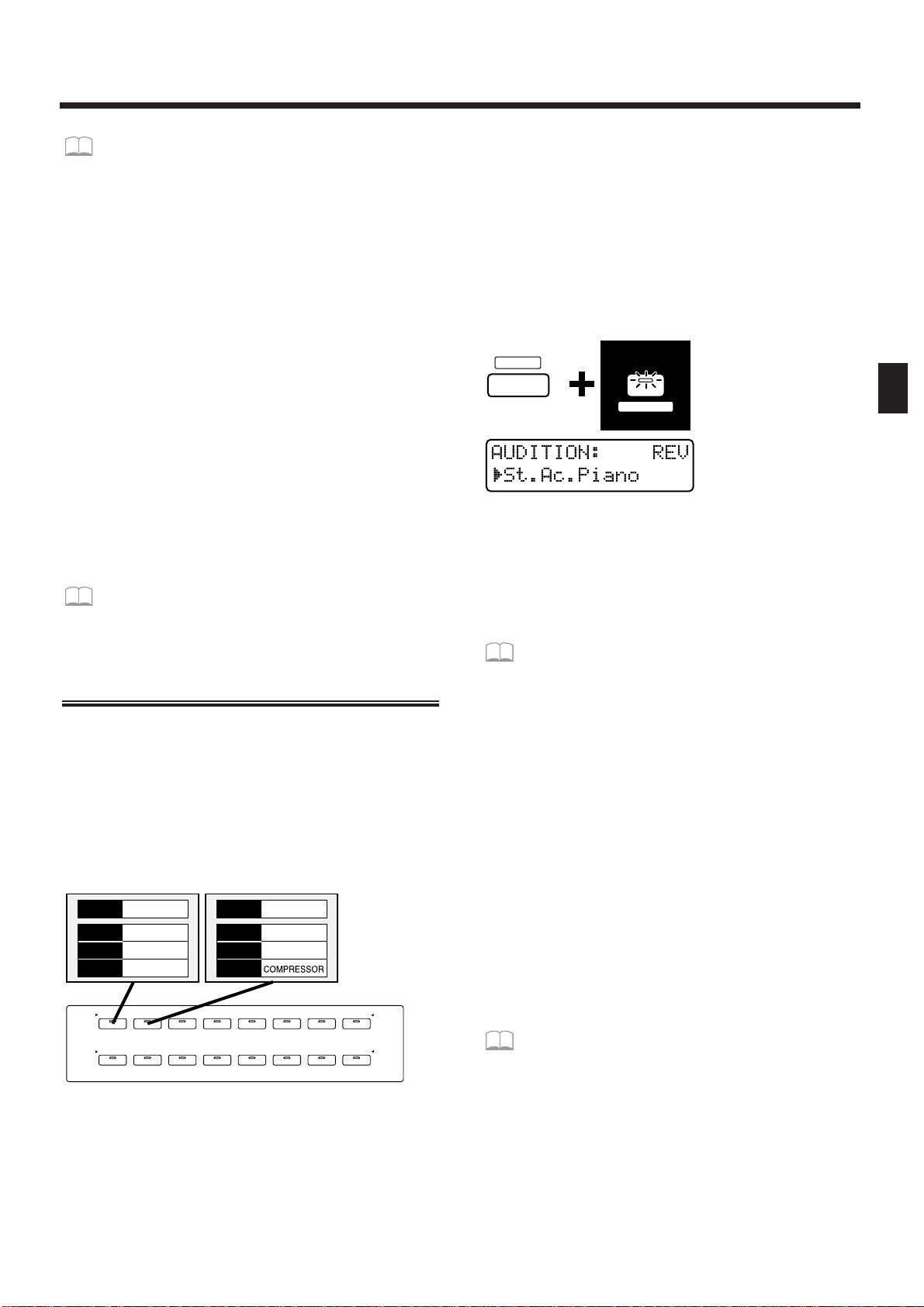
☞ “Using Memory Cards” (p. 159)
4. Press [PART SELECT] once again.
The [PART SELECT] indicator goes out, and you can
now use BANK and NUMBER [1]–[8] to select a
rhythm set.
5. Press BANK [1]–[4] to select the bank.
6. Press NUMBER [1]–[8] to select the number.
Play the keyboard, and the selected rhythm set will be
heard. Each key will play a different percussion instrument sound.
* If the [PART SELECT] or [PART MUTE] indicators in
the PART section are lit, steps 5 and 6 cannot be performed. In this case, press [PART SELECT] or [PART
MUTE] to make the indicator go dark.
* Instead of specifying the group/bank/number, you can
also use [INC] [DEC] or the [VALUE] dial to select a
patch.
* Depending on the group and bank, it may not be possible
to select all numbers [1]–[8].
To view a list of available rhythm sets...
☞ “Preset Rhythm Set List” (p. 195)
Listening to Sound Processed
by the Effects (Audition)
The JX-305 contains three effects units. Thirty-two different settings for these three effects units, together
with a patch/rhythm set are provided as Effect
Templates (16 for patches, 16 for rhythm sets). The
Audition function lets you use these effects templates
to listen to the sound of a patch as it is processed by
the effects units. Effect templates are assigned to the
sixteen BANK and NUMBER [1]–[8] buttons.
fig.2-3-1Åi8-8BUTTONÅj
1. Use [PART SELECT] and PART [1]–[R] to specify whether you will use an effects template for a patch or for a rhythm set.
For parts 1–7, use one of the patch effects templates.
For part R, use one of the rhythm set effects templates.
2. Hold down [SHIFT] and press [AUDITION].
The indicator will begin blinking, and the display will
show the effect type and patch name for the currently
selected effects template.
fig.2-3-2ÅiBUTTON&LCDÅj
* It is not possible to enter the audition function while a
pattern is playing back.
3. Use BANK and NUMBER [1]–[8] to select an
effects template.
To see the effects templates that are available...
☞ “Effects Template List” (p. 203)
4. You can use [INC] [DEC] or the [VALUE] dial
to change only the patch without changing
the effects settings.
If you wish to modify the effects settings, use the procedure given in “Applying Effects to the Sound
(Effects)” (p. 101).
5. To exit the Audition function, press [EXIT].
* When you select a effects template, the setup parameters
of the temporary pattern will change to the settings of the
template.
* It is not possible to select the effects template while a pat-
tern is playing back.
* If you wish to keep the modified effects settings, it is not
possible to rewrite the template, but you can save the data
to a pattern.
☞ “Saving Patterns You’ve Modified (Pattern
Write)” (p. 36)
* A noise-like sound may be heard when the NUMBER [5]
template for rhythm sets is selected, but this is not a malfunction.
12345678
12345678
NUMBER
BANK
1234567R
RHYTHM
PART
BD SD HH CLP CYM
TOM/PERC
HIT OTHERS
St.Ac.Piano
ROOM1
SHORT
REVERB
PATCH
REVERB
DELAY
M-FX
Ac.Piano 1
ROOM1
LONG
PATCH
REVERB
DELAY
M-FX
SHIFT
PATCH
AUDITION
Chapter 2. Playing the Keyboard
29
2
Page 30
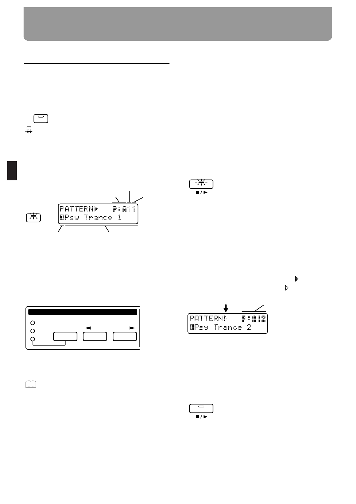
Playing Patterns
1. Make sure that the SEQUENCER section
[MODE] button indicator is dark.
If it is not dark, press [MODE] to make it go dark
(Pattern mode).
fig.3-1 (#MC fig.2-1)
2. Press [PTN/SONG] in the DISPLAY section.
The indicator will light.
The display will indicate the group, bank, number and
name of the currently selected pattern.
fig.3-2E
3. Press [PRESET/USER/CARD] in the GROUP
section to select the group.
Pattern groups are organized as follows.
PRESET → P:A–L (Preset group)
USER → U:A–D (User group)
CARD → C:A–D (Card group)
fig.3-3 (#MC fig.2-3)
* The card group can be selected only if an optional memory
card is inserted.
☞ “Using Memory Cards” (p. 159)
* When all three indicators of the GROUP section are dark,
TMP (the temporary pattern) is selected.
4. Press [<PREV] [NEXT>] in the GROUP section to select group A–L.
5. Use [INC] [DEC] or the [VALUE] dial to select
the bank and number.
Range: P:A11–P:L88, U:A11–U:D18, C:A11–C:D18
The bank, number and name in the display will
change.
A pattern has now been selected.
* P:E33–P:L88 are RPS patterns. Each pattern contains
one phrase.
●●●●●●●●●●●●●●●●●●●●●●●●●●●●●●●●●●●●●●●●●●●●●●●●●●●●●●●●●●●●●●●●●●●●●●●●●●●●●●●●●●●●●●●●●●●●●●●●●●●●
Instead of using [INC] [DEC] or the [VALUE] dial,
you can also select patterns using BANK and NUMBER [1]–[8].
If you wish to use BANK and NUMBER [1]–[8] to
select patterns, make the [PART SELECT] and [PART
MUTE] indicators go dark.
●●●●●●●●●●●●●●●●●●●●●●●●●●●●●●●●●●●●●●●●●●●●●●●●●●●●●●●●●●●●●●●●●●●●●●●●●●●●●●●●●●●●●●●●●●●●●●●●●●●●
6. Press [STOP/PLAY] and the pattern will
play back.
fig.3-4
The pattern that is currently playing back is referred to
as the “current pattern,” and the pattern that is scheduled to play next is called the “next pattern.”
Immediately after a pattern is played back, the current
pattern and the next pattern will be the same pattern,
and that pattern will play back repeatedly.
7. Use steps 3–5 to select the next pattern.
The display will indicate the group, bank, number and
name of the next pattern.
When you select the next pattern, the “ ” at the left
of the pattern group will change to “ .”
fig.3-4-1E
8. When the current pattern plays to the end,
the next pattern will automatically be
selected.
9. Press [STOP/PLAY] and the pattern will
stop playing.
fig.3-5
* Immediately before the pattern changes or repeats, the fol-
lowing display will appear, notifying you that the pattern
is about to change. During this time it is not possible to
select the next pattern.
fig.3-6E
PATTERN
SONG
MODE
SONG
PTN /
Bank
NumberGroup
NameCurrent part
PREV NEXT
PRESET
USER
CARD
GROUP
STOP/PLA Y
Next pattern
STOP/PLA Y
Chapter 3. Playing Patterns
30
Page 31

* If you press [STOP/PLAY] to stop playback after select-
ing the next pattern, the pattern that you had reserved
will be canceled.
* With the factory settings, the User group contain empty
patterns that contain no musical data. Even if you select
an empty pattern, it will not play back. If you specify an
empty pattern as the next pattern, playback will stop the
instant that the pattern changes.
●●●●●●●●●●●●●●●●●●●●●●●●●●●●●●●●●●●●●●●●●●●●●●●●●●●●●●●●●●●●●●●●●●●●●●●●●●●●●●●●●●●●●●●●●●●●●●●●●●●●
Fast-forward and rewind
Each time you press [FWD], the pattern will advance
one measure. Each time you press [BWD], the pattern
will go back one measure.
If you hold down [FWD] and press [BWD], you will
advance to the last measure. If you hold down [BWD]
and press [FWD], you will return to the beginning.
When a pattern is stopped, “ ” will sometimes be
displayed in the display. This indicates that the pattern was stopped in the middle of the measure.
fig.3-7
●●●●●●●●●●●●●●●●●●●●●●●●●●●●●●●●●●●●●●●●●●●●●●●●●●●●●●●●●●●●●●●●●●●●●●●●●●●●●●●●●●●●●●●●●●●●●●●●●●●●
●●●●●●●●●●●●●●●●●●●●●●●●●●●●●●●●●●●●●●●●●●●●●●●●●●●●●●●●●●●●●●●●●●●●●●●●●●●●●●●●●●●●●●●●●●●●●●●●●●●●
Changing patterns instantly
By holding down [SHIFT] and press PAGE [<] [>]
while a pattern is playing back, you can switch immediately to the previous or next pattern. In this case the
pattern will play back the optimal tempo for that pattern.
Also, if you make a new recording and create a pattern
that is only one measure long, and play back this pattern, it will in some cases be impossible to use [INC]
[DEC], the [VALUE] dial or PAGE [<] [>] to select the
next pattern. In such cases, holding down [SHIFT] and
use PAGE [<] [>] to change patterns.
●●●●●●●●●●●●●●●●●●●●●●●●●●●●●●●●●●●●●●●●●●●●●●●●●●●●●●●●●●●●●●●●●●●●●●●●●●●●●●●●●●●●●●●●●●●●●●●●●●●●
If you would like to know what kind of pat-
terns are available...
☞ “Preset Pattern List” (p. 204)
Adjusting the Tempo
The tempo can be adjusted freely even while a pattern
is playing back.
1.
In the DISPLAY section, press [TEMPO& MEASURE].
Indicator will light, and the upper line of the display
will show the current tempo value.
fig.3-8
2. Use the [VALUE] dial to modify the tempo
(20.0–240.0 BPM).
The tempo can be adjusted in 0.1 BPM steps.
By holding down [SHIFT] and rotating the [VALUE]
dial, you can adjust the tempo in 1 BPM units.
●●●●●●●●●●●●●●●●●●●●●●●●●●●●●●●●●●●●●●●●●●●●●●●●●●●●●●●●●●●●●●●●●●●●●●●●●●●●●●●●●●●●●●●●●●●●●●●●●●●●
BPM
BPM stands for Beats Per Minute, and indicates the
number of quarter notes that occur in one minute.
Standard tempo
An optimal tempo is already set for each pattern. This
is called the “standard tempo.”
If you select another pattern while pattern playback is
stopped, the tempo will change to the standard tempo
of that pattern. When you use [INC] [DEC] or the
[VALUE] dial to switch to another pattern during pattern playback, the tempo value of the previous pattern
will be maintained.
●●●●●●●●●●●●●●●●●●●●●●●●●●●●●●●●●●●●●●●●●●●●●●●●●●●●●●●●●●●●●●●●●●●●●●●●●●●●●●●●●●●●●●●●●●●●●●●●●●●●
Viewing the Number of
Measures in a Pattern
If you wish to know the total number of measures in
the current pattern, or the current playback location,
use the following procedure.
1. Press [TEMPO&MEASURE].
The lower line of the display will show the number of
measures in the entire pattern, and the playback location (measure and beat). In the example shown below,
“Total number of measures = 16 measures” “Playback
location = third beat of measure 12”
fig.3-8 (#MC fig.2-8)
2. To return to the pattern select page, press
[PTN/SONG].
Next patternCurrent pattern
MEASURE
TEMPO&
MEASURE
TEMPO&
Chapter 3. Playing Patterns
31
3
Page 32

Muting a Specific Part (Part
Mute/Rhythm Mute)
During pattern playback, you can mute the playback
of a specific part or rhythm tone.
1. Press [PART MUTE].
The [PART MUTE] indicator will light, and the PART
button [1]– [R] indicators will show the current status
of that part.
The RHYTHM button [BD]– [OTHERS] indicators will
also show the current status of that rhythm group.
fig.3-11 (#MC fig.2-11)
Blinking: The playback data is muted.
Lit: The playback data is not muted.
Dark: There is no playback data.
2. Press the button of the part or rhythm
group that you wish to mute.
The indicator of the button you pressed will begin
blinking, and the playback data will be muted.
fig.3-12 (#MC fig.2-12)
To cancel muting, press the button for the muted part
or rhythm group to make the indicator light.
* The indicator will not light even if you press the button of
a part or rhythm group which is dark.
* None of the preset patterns (P:A11-P:E32) contain play-
back data for part 1.
You can change the mute status of each part,
and save the setting in a user pattern.
☞ “Saving Patterns You’ve Modified (Pattern
Write)” (p. 36)
* Rhythm mute settings will not be active if the Part Mute
function has been used to mute the rhythm part itself.
* The rhythm tones that are muted by each RHYTHM but-
ton will depend on the selected rhythm set.
If you would like to know which rhythm tones
correspond to each rhythm group...
☞ “Preset Rhythm Set List” (p. 195)
●●●●●●●●●●●●●●●●●●●●●●●●●●●●●●●●●●●●●●●●●●●●●●●●●●●●●●●●●●●●●●●●●●●●●●●●●●●●●●●●●●●●●●●●●●●●●●●●●●●●
Other type of muting
In addition to Part Mute and Rhythm Mute, a variety
of other muting operations are available. Use them as
appropriate for your needs.
Simultaneously muting all parts (All Mute)
Hold down [SHIFT] and press [PART MUTE].
The indicator of [PART MUTE] will blink and all parts
will be muted. Perform the same operation once again
to return to the previous condition.
Playing back only a specific part (Monitor)
Hold down [PART MUTE] and press the PART button
for the part that you wish to hear.
Exchanging the mute status of all parts (Mute
Exchange)
Hold down [PART MUTE] and press [PART SELECT].
●●●●●●●●●●●●●●●●●●●●●●●●●●●●●●●●●●●●●●●●●●●●●●●●●●●●●●●●●●●●●●●●●●●●●●●●●●●●●●●●●●●●●●●●●●●●●●●●●●●●
Transposing During Playback
(Real-Time Transpose)
Using the VALUE Dial or [INC]
[DEC]
1. Hold down [TRANSPOSE] and use the
[VALUE] dial or [INC] [DEC] to specify the
transpose value.
Range: -12–+12 semitones (factory setting is +4)
fig.3-14 (#MC fig.2-16)
The display will indicate the current setting while you
continue pressing the button. When you modify the
transpose value, the " " at the left of the transpose
value will change to " ."
2. The transposition will be applied from the
moment that you release the button.
To return to the original key, press [TRANSPOSE]
once again to make the button indicator go dark.
MUTE
PART
12345678
12345678
NUMBER
BANK
1234567R
RHYTHM
PART
BD SD HH CLP CYM
TOM/PERC
HIT OTHERS
TRANSPOSE
Chapter 3. Playing Patterns
32
Page 33

Using the Keyboard
1. Hold down [TRANSPOSE] and press a key
to set the transpose value.
The transpose value can be set in a range of -12–+12
semitones, above and below the C4 key.
fig.3-15 (#MC fig.2-17)
2. The transposition will be applied from the
moment that you press the keyboard.
To return to the original key, press [TRANSPOSE]
once again to make the button indicator go dark.
Changing the Settings of Each Part
The settings of a pattern (the volume and pan of each
part, etc.) can be modified in the following two ways.
Using the Part Mixer Page to
Make Changes
In the Part Mixer page, the setting values of each part
are displayed graphically. Here you can also record
the modified settings to a pattern.
☞ “Recording Part Mixer Operations” (p. 128)
fig.3-16
1. Hold down [SHIFT] and press [MIXER].
The indicator will light and the display will show the
Part Mixer page.
2. Use PART [1]–[R] to select the part for
which you wish to make settings.
3. Use PAGE [<] [>] to select the parameter
that you wish to set.
4. Use [INC] [DEC] or the [VALUE] dial to set
the value.
●●●●●●●●●●●●●●●●●●●●●●●●●●●●●●●●●●●●●●●●●●●●●●●●●●●●●●●●●●●●●●●●●●●●●●●●●●●●●●●●●●●●●●●●●●●●●●●●●●●●
When you enter the Part Mixer page, all indicators of
[ENVELOPE/LFO1/EFFECTS], [FILTER/AMP/PITCH]
and [GRID/SHUFFLE/GROOVE] will blink, and you
can use the eight knobs of the REALTIME MODIFY
section and the QUANTIZE section to adjust the settings of each part. At this time, the QUANTIZE settings or REALTIME MODIFY cannot be modified by
the knobs.
fig.3-17
●●●●●●●●●●●●●●●●●●●●●●●●●●●●●●●●●●●●●●●●●●●●●●●●●●●●●●●●●●●●●●●●●●●●●●●●●●●●●●●●●●●●●●●●●●●●●●●●●●●●
5. Press [EXIT] to exit the Part Mixer page.
Adjusting the volume of each part
(Part Level)
fig.3-18
Range: 0–127
With a setting of “127,” the volume setting of the patch
itself will be fully active.
Adjusting the pan of each part (Part Pan)
You can adjust the stereo location in the stereo output
from the OUTPUT jacks. For example, you might place
the drums and bass in the center, the piano at right,
and a pad at left.
fig.3-19
Range: L64–63R
C4
TRANSPOSE
PAGE
LOWER UPPER
SHIFT
MEASURE
TEMPO&
MIXER
CUTOFF
LEVEL
PORTA TIME
RESONANCE
PANPOT
FINE TUNE
ENVELOPE
LFO1
EFFECTS
RATE
REVERB LEVEL
FADE TIME
DELAY LEVEL
PITCH DEPTH
MULTI CTRL1
FILTER DEPTH
MULTI CTRL2
AMP DEPTH
MULTI CTRL3
GRID
SHUFFLE
GROOVE
TIMING
VELOCITY
QUANTIZEREALTIME MODIFY
ATTACK DECAY SUSTAIN RELEASE DEPTH FILTER
AMP
PITCH
12345 67 R
PART
Chapter 3. Playing Patterns
33
3
Page 34

When this setting is at “0,” the setting of the patch
itself will be unaffected.
* Pan is specified independently for each tone of a patch (or
each rhythm tone of a rhythm set). Modifying the Part
Pan applies a relative change to the overall panning of the
patch or rhythm set.
* For some patches, a small amount of sound may be heard
from the opposite speaker even if the pan is set to full left
or full right. Also, the Part Pan setting will have no effect
in the following cases.
• When monaural connections are used
• Tones/rhythm tones for which Random Pan is ON
☞ “Causing pan to change randomly (Random
Pan Switch)” (p. 67)
• Patches/rhythm tones to which a mono-output
Multi Effects (spectrum, overdrive, distortion, noise
generator, phonograph, limiter, phaser) is applied
The same applies for the Lo-Fi or Radio Tuning
effects if the output setting of them is set to MONO.
☞ “Applying Various Effects to the Sound
(Multi-Effects)” (p. 106)
Adjusting the pitch of each part (Part
Key Shift)
You can adjust the pitch of the sound of each part.
fig.3-20
Range: -48–+48 semitones
When the value is “0,” the original pitch of the patch
itself will be used without change.
If you hold down [SHIFT] and change the value using
[INC] [DEC] or the [VALUE] dial, the pitch will
change in units of an octave (12 semitones).
Adjusting the reverb volume for each
part (Part Reverb Level)
You can adjust the volume of the reverberation for
each part.
fig.3-21
Range: 0–127
☞ “Adding Reverberation to the Sound
(Reverb)” (p. 102)
Adjusting the delay volume for each
part (Part Delay Level)
You can adjust the volume of the delay sound for each
part.
fig.3-22
Range: 0–127
☞ “Adding an Echo to the Sound (Delay)” (p.
103)
Applying multi-effects to each part
(Part Multi-Effects Switch)
For each part you can switch multi-effects on/off.
fig.3-23
Range:
OFF: Multi-effects will not be applied.
RHY: The sound will be output according to the
Rhythm Tone Multi-Effects Switch, Rhythm
Tone Reverb Level, and Rhythm Tone Delay
Level settings of the selected rhythm set (only
for the rhythm part) (p. 97).
ON: Multi-effects will be applied.
☞ “Applying Various Effects to the Sound
(Multi-Effects)” (p. 106)
Using the Editing Pages to Make
Changes
In the editing pages you can make settings for all part
parameters, but cannot record the modified settings to
a pattern.
1. Press [EDIT].
The indicator will light and the display will show the
Edit page.
2. Press BANK [3] (PART).
The part setting page will appear.
3. Use [PART SELECT] and PART[1]–[R] to select
the part.
4. Use PAGE [<] [>] to switch parameters.
5. Use [INC] [DEC] or the [VALUE] dial to make
settings.
fig.3-24
Chapter 3. Playing Patterns
34
Page 35

5. Press [EXIT] to leave the setting page.
Selecting the patch that will be
assigned to a part
The patch that is assigned to each part is memorized
as part of the pattern settings.
fig.3-25
Adjusting the volume of each part
(Part Level)
fig.3-26
Range: 0–127
With a setting of “127,” the volume setting of the patch
itself will be fully active.
Adjusting the pan of each part (Part
Pan)
You can adjust the stereo location in the stereo output
from the OUTPUT jacks.
fig.3-27
Range: L64–63R
When this setting is at “0,” the setting of the patch
itself will be unaffected.
Adjusting the pitch of each part (Part
Key Shift)
You can adjust the pitch of the sound of each part.
fig.3-28
Range: -48–+48 semitones
When the value is “0,” the original pitch of the patch
itself will be used without change.
Adjusting the reverb volume for each
part (Part Reverb Level)
The volume of reverberation can be specified for each part.
fig.3-29
Range: 0–127
☞ “Adding Reverberation to the Sound
(Reverb)” (p. 102)
Adjusting the delay volume for each
part (Part Delay Level)
The volume of the delay sound can be specified for
each part.
fig.3-30
Range: 0–127
☞ “Adding an Echo to the Sound (Delay)” (p.
103)
Applying multi-effects to each part
(Part Multi-Effects Switch)
Multi-effects can be switched on/off for each part.
fig.3-31
Range:
OFF : Multi-effects will not be applied.
RHY : The sound will be output according to the
Rhythm Tone Multi-Effects Switch, Rhythm
Tone Reverb Level, and Rhythm Tone Delay
FX ON / OFF
EDIT
3
3
PART
PAGE
LOWER UPPER
Chapter 3. Playing Patterns
35
3
Page 36

Level settings of the selected rhythm set
(rhythm part only) (p. 97).
ON : Multi-effects will be applied.
☞ “Applying Various Effects to the Sound
(Multi-Effects)” (p. 106)
Specifying the output destination for
musical data
(Sequencer Output Assign)
You can specify the output destination for the musical
data of each part. For example, if you wish to use the
JX-305 together with a sampler such as the SP-202, you
can set Sequencer Output Assign to “EXT” for one or
more of the parts. This will allow playback data from
the JX-305 sequencer to control the external MIDI
device.
If you want to control an external MIDI device
such as a sampler...
☞ “Controlling an External MIDI Device from
the JX-305” (p. 174)
fig.3-32 (#MC fig.2-31&fig.2-32)
Range:
INT : Musical data from the sequencer will be
sent to the internal sound generator of the
JX-305.
EXT : Musical data from the sequencer will be
sent to an external device via MIDI OUT.
BOTH : Musical data from the sequencer will be
sent both to the internal sound generator
and from MIDI OUT.
* If “EXT” or “BOTH” is selected, that part will not be
heard even if you play back the pattern.
Musical data from parts that are set to EXT will be
transmitted as MIDI messages from MIDI OUT on a
different MIDI channel for each part.
The musical data of each part is transmitted on the following MIDI channels.
Part 1234567R
Channel 123456710
●●●●●●●●●●●●●●●●●●●●●●●●●●●●●●●●●●●●●●●●●●●●●●●●●●●●●●●●●●●●●●●●●●●●●●●●●●●●●●●●●●●●●●●●●●●●●●●●●●●●
If you wish to use the keyboard to directly play an
external MIDI device, set the Local Switch to “EXT.”
☞ “Disconnecting the Keyboard from the
Internal Sound Generator (Local Switch)” (p.
165)
●●●●●●●●●●●●●●●●●●●●●●●●●●●●●●●●●●●●●●●●●●●●●●●●●●●●●●●●●●●●●●●●●●●●●●●●●●●●●●●●●●●●●●●●●●●●●●●●●●●●
Saving Patterns You’ve
Modified (Pattern Write)
If you have modified the patch and part mixer settings
for each part to create a pattern that you wish to keep,
you can save that pattern as a User Pattern.
1. Make sure that the pattern is stopped.
2. Press [PTN/SONG] to access the pattern
select page.
3. Hold down [SHIFT] and press [WRITE].
The indicator will blink.
The following display will appear, and “ ” (the cursor) will appear at the left of the number.
fig.3-33
If you do not wish to change the number or name, you
can skip steps 4–8.
If you decide not to save the pattern, press [EXIT].
4. Press [PRESET/USER/CARD] to select the
save destination group.
* The PRESET group and TMP annot be selected.
* CARD groups can be selected only if an optional memory
card is inserted.
☞ “Using Memory Cards” (p. 159)
5. Use [INC] [DEC] or the [VALUE] dial to select
the save destination bank and number.
You can also use the BANK and NUMBER [1]–[8] buttons to select the save destination bank and number.
Part 1
Part 2
Part 3
Part 4
Part 5
Part 6
Part 7
Part R
SEQ Out Assign = INT
SEQ Out Assign = INT
SEQ Out Assign = INT
SEQ Out Assign = INT
SEQ Out Assign = INT
SEQ Out Assign = INT
SEQ Out Assign = INT
SEQ Out Assign =EXT
SP-202
MIDI OUT
JX-305
Part R
Part 7
Part 6
Part 5
Part 4
Part 3
Part 2
Part 1
SHIFT
UTILITY
WRITE
Chapter 3. Playing Patterns
36
Page 37

●●●●●●●●●●●●●●●●●●●●●●●●●●●●●●●●●●●●●●●●●●●●●●●●●●●●●●●●●●●●●●●●●●●●●●●●●●●●●●●●●●●●●●●●●●●●●●●●●●●●
At this time, you can press [UNDO/REDO] to check
the name of the pattern that is currently in the save
destination number. After you have found a pattern
that you do not mind overwriting, press
[UNDO/REDO] once again to return to the previous
display.
●●●●●●●●●●●●●●●●●●●●●●●●●●●●●●●●●●●●●●●●●●●●●●●●●●●●●●●●●●●●●●●●●●●●●●●●●●●●●●●●●●●●●●●●●●●●●●●●●●●●
6. Press PAGE [>].
The cursor will move to the beginning of the second
line of the display.
fig.3-34
7. Assign a name to the pattern.
Use [INC] [DEC] or the [VALUE] dial to select characters.
The following characters are available.
space, A–Z, a–z, 0–9, ! “ # $ % & ‘ ( ) * +, - . / : ; < = > ?
@ [ ¥ ] ^ _ ` {|}
8. Repeat steps 6–7 to input the name.
You can move the cursor back toward the left by
pressing PAGE [<].
9. Press [ENTER].
The confirmation screen will appear in the display.
If you decide to cancel the operation, press [EXIT].
fig.3-35
10. Press [ENTER] once again.
fig.0-5
The Pattern Write operation will be carried out, then
the normal display will reappear.
The pattern has now been saved.
●●●●●●●●●●●●●●●●●●●●●●●●●●●●●●●●●●●●●●●●●●●●●●●●●●●●●●●●●●●●●●●●●●●●●●●●●●●●●●●●●●●●●●●●●●●●●●●●●●●●
On the JX-305, the following parameters are memorized for each pattern.
Standard Tempo (p. 31)
Patch Number * (p. 18)
Part Level * (p. 33)
Part Pan * (p. 33)
Part Key Shift * (p. 34)
Part Reverb Level * (p. 34)
Part Delay Level * (p. 34)
Part Multi-Effects Switch * (p. 34)
Reverb settings # (p. 102)
Delay settings # (p. 103)
Multi Effects settings (p. 106)
Part Mute status * (p. 32)
Rhythm Mute status (p. 32)
Sequencer Output Assign * (p. 36)
Key Mode # (p. 18)
Split Point # (p. 20)
Part number assigned to the upper part # (p. 20)
Part number assigned to the lower part # (p. 20)
* The “*” indicates parameters that are set independently
for each part.
* If you switch patterns while playback is stopped, “#” set-
tings will be updated. However, if you switch patterns
during playback, These parameters will maintain the setting of the previous pattern.
These parameters are collectively referred to as the
“setup parameters.”
●●●●●●●●●●●●●●●●●●●●●●●●●●●●●●●●●●●●●●●●●●●●●●●●●●●●●●●●●●●●●●●●●●●●●●●●●●●●●●●●●●●●●●●●●●●●●●●●●●●●
Copying and Initializing Settings
Setup Copy
This operation copies the setup parameters of a specified pattern to the temporary pattern.
1. Press [PTN/SONG] to access the pattern
select page.
2. Press [UTILITY].
The indicator will light.
3. Press PAGE [<] [>] several times to select
“COPY,” and press [ENTER].
4. Press PAGE [<] [>] several times to select
“SETUP PARAM,” and press [ENTER].
The display will indicate the copy source pattern, copy
source part, and copy destination part.
fig.3-37
5. Use [INC] [DEC] or the [VALUE] dial to specify the copy source pattern, the copy source
part, and the copy destination part.
You can move the cursor by pressing PAGE [<] [>].
Available settings for the part:
P1–P7, R: Setup parameters of the specified part
FX: Effects setup parameters
ALL: All setup parameters
If the copy source part setting is “R,” “FX” or “ALL,”
it will not be possible to specify the copy destination
part.
6. Press [ENTER].
The confirmation screen will appear in the display.
If you decide to cancel the operation, press [EXIT].
fig.3-38
Chapter 3. Playing Patterns
37
3
Page 38

7. Press [ENTER] once again.
fig.0-5
The Setup Copy operation will be carried out, then the
normal display will reappear.
To save the copied pattern, use the Pattern Write operation.
☞ “Saving Patterns You’ve Modified (Pattern
Write)” (p. 36)
Pattern Initialize
This operation initializes a pattern to a state of containing no musical data (empty pattern).
1. Press [PTN/SONG] to access the pattern
select page.
2. Select the pattern that you wish to initialize.
* It is not posibble to initialize if you select a preset pattern.
3. Press [UTILITY].
The indicator will light.
4. Press PAGE [<] [>] several times to select
“INITIALIZE,” and press [ENTER].
5. Select “PATTERN,” and press [ENTER].
The following display will appear.
fig.3-40
6. Press [ENTER].
fig.0-5
The Pattern Initialize operation will be carried out,
then the normal display will reappear.
The pattern that was initialized will be saved automatically.
Using the Knobs to Modify
the Sound During Playback
(Real-Time Modify)
You can freely modify the sound of a patch by moving
the sound parameter knobs while a pattern is playing.
This capability is referred to as Real-Time Modify, and
is especially effective when used during a live performance. Realtime Modify adjusts the tone of the entire
patch (rhythm set) selected for the current part, or the
tone of an entire rhythm group.
1. Select a pattern, and play it (p. 30).
2. Use [PART SELECT] and PART [1]–[R] to
select the part.
fig.2-1
●●●●●●●●●●●●●●●●●●●●●●●●●●●●●●●●●●●●●●●●●●●●●●●●●●●●●●●●●●●●●●●●●●●●●●●●●●●●●●●●●●●●●●●●●●●●●●●●●●●●
The part(s) affected by Realtime Modify
The part(s) whose sound will be affected by Realtime
Modify will depend on the Key Mode.
Single: The sound of the current part will be
affected.
Split: The sound of the upper part will be affect-
ed when the [UPPER] indicator is lit, and
the lower part when the [LOWER] indicator is lit.
Dual: The sounds of both the upper and lower
parts will be affected.
●●●●●●●●●●●●●●●●●●●●●●●●●●●●●●●●●●●●●●●●●●●●●●●●●●●●●●●●●●●●●●●●●●●●●●●●●●●●●●●●●●●●●●●●●●●●●●●●●●●●
3. Use the knobs to modify the sound.
fig.3-43
* When modifying the rhythm part, parameters of LFO1
and PORTAMENTO are not used.
If you wish to learn about the function of each
knob and button...
☞“Creating Original Sounds (Patch Edit)” (p.
53)
☞“Creating an Original Rhythm Set (Rhythm
Edit)” (p. 85)
12345678
SELECT
PART
MUTE
PART
CTRL
MUTE
PREV NEXT
PRESET
USER
CARD
UTILITY
BANK
1234567R
PART
WRITE
FX ON/ OFF
QTZ SELECT
EDIT/ UTILITY
GROUP PART
EDIT
CUTOFF
LEVEL
PORTA TIME
RESONANCE
PANPOT
FINE TUNE
ENVELOPE
LFO1
EFFECTS
RATE
REVERB LEVEL
FADE TIME
DELAY LEVEL
PITCH DEPTH
MULTI CTRL1
FILTER DEPTH
MULTI CTRL2
AMP DEPTH
MULTI CTRL3
REALTIME MODIFY
ATTACK DECAY SUSTAIN RELEASE DEPTH FILTER
AMP
PITCH
Chapter 3. Playing Patterns
38
Page 39

●●●●●●●●●●●●●●●●●●●●●●●●●●●●●●●●●●●●●●●●●●●●●●●●●●●●●●●●●●●●●●●●●●●●●●●●●●●●●●●●●●●●●●●●●●●●●●●●●●●●
You can switch the current part during playback to
change the part that you are modifying.
●●●●●●●●●●●●●●●●●●●●●●●●●●●●●●●●●●●●●●●●●●●●●●●●●●●●●●●●●●●●●●●●●●●●●●●●●●●●●●●●●●●●●●●●●●●●●●●●●●●●
Modifying the Sound for an
Individual Rhythm Group
In the rhythm part, a different rhythm tone is assigned
to each key, and you can use Real-Time Modify to
modify the sound of rhythm tone groups such as Bass
Drum or Snare Drum.
1. Select a pattern, and play it (p. 30).
2. Select the rhythm part as the current part.
fig.2-52
The indicator will light, and the RHYTHM buttons
will indicate the rhythm group that is selected for
Real-Time Modify.
fig.3-46 (#MC fig.2-48)
Rhythm groups with button indicators that are lit will
be affected by Real-Time Modify.
For example, if you select [TOM/PERC], all toms and
percussion-type rhythm tones in the rhythm set can be
modified.
3. Press a button [BD]– [OTHERS] to select the
rhythm group that will be affected by RealTime Modify.
The indicator of the selected button will light.
* It is not possible to select two or more groups simultane-
ously.
If no rhythm group is selected, all rhythm groups will
be affected by Realtime Modify.
4. Use the knobs to modify the sound.
●●●●●●●●●●●●●●●●●●●●●●●●●●●●●●●●●●●●●●●●●●●●●●●●●●●●●●●●●●●●●●●●●●●●●●●●●●●●●●●●●●●●●●●●●●●●●●●●●●●●
In addition to this, you can also modify each rhythm
tone in the Rhythm Edit page.
☞ “Creating an Original Rhythm Set” (Rhythm
Edit) (p. 85)
By selecting a different part or rhythm group, you can
change the object of your modifications even while the
pattern is playing.
When the same pattern plays back repeatedly in
Pattern mode, the modified parameter settings will
remain as they are even if you return to the beginning
of the pattern.
These knob movements are referred to as “modify
data,” and can be recorded in a pattern.
☞ “Recording Knob Movements (Modify
Data)” (p. 128)
●●●●●●●●●●●●●●●●●●●●●●●●●●●●●●●●●●●●●●●●●●●●●●●●●●●●●●●●●●●●●●●●●●●●●●●●●●●●●●●●●●●●●●●●●●●●●●●●●●●●
Returning a Pattern to Its Original
State During Playback (Pattern Reset)
When you use Real-Time Modify, the pattern will
remain in its modified state until a different pattern is
selected. Here’s how you can restore a modified pattern to its original state during playback.
Restoring only the patch of a specific
part that was modified
1. Press [PATCH] to access the patch select
page.
2. Select the part that you wish to restore as
the current part.
3. Press [UNDO/REDO].
The following display will appear.
fig.3-48-01
4. Press [ENTER] to return to the previous
patch.
The “*” (asterisk) at the left of the patch number will
disappear.
fig.3-48-02
12345678
SELECT
PART
MUTE
PART
CTRL
MUTE
PREV NEXT
PRESET
USER
CARD
UTILITY
BANK
1234567R
PART
WRITE
FX ON/ OFF
QTZ SELECT
EDIT/ UTILITY
GROUP PART
EDIT
BD SD HH CLP CYM
TOM/PERC
HIT
OTHERS
Select
UNDO
/REDO
ERASE
Chapter 3. Playing Patterns
39
3
Page 40

Restoring the patch (rhythm set) and
part mixer settings of all parts that
were modified
1. In the pattern select page, re-select the pattern that is currently playing (p. 30).
The pattern will return to the beginning, and the original settings will be restored.
●●●●●●●●●●●●●●●●●●●●●●●●●●●●●●●●●●●●●●●●●●●●●●●●●●●●●●●●●●●●●●●●●●●●●●●●●●●●●●●●●●●●●●●●●●●●●●●●●●●●
The relation between modify data that was
recorded and modify data from the knobs
If you perform Real-Time Modify while playing back a
part for which modify data has already been recorded,
the manual knob movements will take priority, and
the modify data within the musical data for that part
will be canceled, and will not be sent to the sound generator. (Note messages in the musical data will be sent
to the sound generator regardless of knob operations.)
fig.3-49TEXT (=MC fig.2-52)
Modify Data that was canceled will once again be
transmitted to the sound generator when the pattern
returns to its beginning, or when you select a different
pattern.
* Each knob has eleven switching points as calibrated on the
panel. Modify Data within the musical data will be canceled from the moment that a knob is moved through one
of these points.
fig.3-50TEXT (#MC fig.2-53)
●●●●●●●●●●●●●●●●●●●●●●●●●●●●●●●●●●●●●●●●●●●●●●●●●●●●●●●●●●●●●●●●●●●●●●●●●●●●●●●●●●●●●●●●●●●●●●●●●●●●
Ensuring Correct Playback from
the Middle of a Pattern
(MIDI Update)
When a pattern is played back from the middle after
fast-forward or rewind, some parts (depending on the
pattern) may have incorrect pitch or volume. This is
because when you move to a different location within
a pattern, the musical data that was “skipped over” is
not transmitted to the sound generator. In such cases,
use the MIDI Update function so that the musical data
(other than note messages) that lies between the beginning of the pattern and the current location will be
transmitted to the sound generator, ensuring that
playback will occur correctly.
1. Make sure that the pattern is stopped.
2. Hold down [SHIFT] and press [STOP/PLAY].
While this operation is being performed, the following
display will appear.
fig.3-51 (#MC fig.2-54)
Changing the Groove of a
Pattern (Play Quantize)
Play Quantize is a function which modifies the pattern
that is being played back by correcting or skewing the
timing of the notes according to a specified rule. This
means that you can modify only the timing with
which the pattern will play back, without affecting the
contents of the data itself.
The JX-305 provides three types of quantization,
which you can use as appropriate for your situation.
You can apply Play Quantize to a specified part while
a pattern plays back, and make detailed timing adjustments in real time while you listen to the playback.
* Quantization affects only the timing of the note messages
(the timing at which notes are played and released), and
does not modify the timing of other messages. This means
that if a pattern contains messages (such as pitch bend)
that apply real-time change to the sound, quantization
settings may cause the timing of these messages to no
longer match the timing of the note messages, so that
playback will be incorrect. When applying quantization, it
is best to use a pattern which does not contain messages
that apply real-time change to the sound.
Note data
canceled
Modify data
Note data
Modify data
Sound
source
section
Modify data
from knob
movements
Realtime Modify begins
Musical data of Part 1
Switch point Modify data is canceled
SHIFT
STOP/PLA Y
Chapter 3. Playing Patterns
40
Page 41

Selecting Parts to Use with Play
Quantize
Play Quantize can be applied to the playback of a specific part. Before you apply Play Quantize, you must
specify the part(s) to which it will apply.
1. Hold down [SHIFT] and press [QTZ SELECT].
The button indicator will blink.
fig.3-52 (#MC fig.7-1)
2. Use PART [1]–[R] to select the part(s) to
which you wish to apply Play Quantize.
Play Quantize will be applied to the parts whose indicators are lit.
fig.3-53 (#MC fig.7-2)
You can simultaneously select more than one part.
Correcting Inaccuracies in the
Rhythm (Grid Quantize)
Grid Quantize will quantize the pattern playback timing to the nearest specified note value. This will cause
the pattern to play back with accurate timing.
fig.3-54 (=MC fig.7-3)
* When Grid Quantize is used, the playback timing will be
correct, but conversely this may produce a mechanical,
inhuman feel. If you wish to preserve the feel of the performance, you can set Resolution to a fine value, or lower the
Strength setting.
Specifying the Unit (Resolution)
The note value unit to which quantization will adjust
the timing is called the Resolution. The timing of notes
will be adjusted to the nearest grid interval of the note
value you specify here. Set this to the length of the
smallest note value that occurs in the pattern.
1. Press [PTN/SONG].
2. Press [GRID/SHFFLE/GROOVE] several
times to make the GRID indicator light.
fig.3-57
3. Press [EDIT].
The indicator will light and the display will show the
Edit page.
4. Press NUMBER [7] (QUANTIZE).
The Grid Quantize setting page will appear.
fig.3-55 (#MC fig.7-4)
5. Use [INC] [DEC] or the [VALUE] dial to set
the Resolution.
Range:
To exit the setting page, press [EXIT].
●●●●●●●●●●●●●●●●●●●●●●●●●●●●●●●●●●●●●●●●●●●●●●●●●●●●●●●●●●●●●●●●●●●●●●●●●●●●●●●●●●●●●●●●●●●●●●●●●●●●
When the GRID indicator is lit, you can also hold
down [GRID/SHUFFLE/GROOVE] and rotate the
[VALUE] dial to modify the Resolution.
●●●●●●●●●●●●●●●●●●●●●●●●●●●●●●●●●●●●●●●●●●●●●●●●●●●●●●●●●●●●●●●●●●●●●●●●●●●●●●●●●●●●●●●●●●●●●●●●●●●●
Applying Grid Quantize
1. Play back the pattern that you wish to
quantize.
2. Press [GRID/SHUFFLE/GROOVE] several
times to make the GRID indicator light.
fig.3-57 (#MC fig.7-6)
3. Grid Quantize will be applied to the playback data according to the Resolution setting.
4. In the QUANTIZE section, rotate the [TIMING] knob to adjust the Strength.
Range: 0–100%
fig.3-58 (#MC fig.7-7)
SELECT
PART
QTZ SELECT
SHIFT
123
456
7
R
GRID
SHUFFLE
GROOVE
FX ON / OFF
EDIT
7
HIT
QUANTIZE
PAGE
LOWER UPPER
GRID
SHUFFLE
GROOVE
Chapter 3. Playing Patterns
41
3
Page 42

Strength specifies the degree to which the note timing
will be corrected toward the note value specified by
Resolution. Rotating the knob clockwise will cause the
notes to be corrected all the way to their correct timing.
When this setting is at “0%,” the notes will be played
at their original (un-quantized) timing.
●●●●●●●●●●●●●●●●●●●●●●●●●●●●●●●●●●●●●●●●●●●●●●●●●●●●●●●●●●●●●●●●●●●●●●●●●●●●●●●●●●●●●●●●●●●●●●●●●●●●
In the Grid Quantize setting page, you can use PAGE
[<] [>] to access the Strength setting page and view the
numerical value of the knob setting while you apply
quantization.
fig.3-58-1
●●●●●●●●●●●●●●●●●●●●●●●●●●●●●●●●●●●●●●●●●●●●●●●●●●●●●●●●●●●●●●●●●●●●●●●●●●●●●●●●●●●●●●●●●●●●●●●●●●●●
Giving Swing to the Rhythm
(Shuffle Quantize)
By applying Shuffle Quantize, you can adjust the timing of the backbeats of the pattern to create “bouncy”
rhythms such as shuffle or swing.
fig.3-59 (=MC fig.7-8)
Specifying the Unit (Resolution)
Specifies the Resolution. The timing of notes will be
adjusted to the nearest grid interval of the note value
you specify here. Set this to the length of the smallest
note value that occurs in the pattern.
1. Press [PTN/SONG].
2. Press [GRID/SHFFLE/GROOVE] several
times to make the SHUFFLE indicator light.
fig.3-62
3. Press [EDIT].
The indicator will light and the display will show the
Edit page .
4. Press NUMBER [7] (QUANTIZE).
The Shuffle Quantize setting page will appear.
fig.3-60 (#MC =fig.7-9)
5. Use [INC] [DEC] or the [VALUE] dial to specify the Resolution.
Range:
To exit the setting page, press [EXIT].
●●●●●●●●●●●●●●●●●●●●●●●●●●●●●●●●●●●●●●●●●●●●●●●●●●●●●●●●●●●●●●●●●●●●●●●●●●●●●●●●●●●●●●●●●●●●●●●●●●●●
When the SHUFFLE indicator is lit, you can also hold
down [GRID/SHUFFLE/GROOVE] and rotate the
[VALUE] dial to modify the Resolution.
●●●●●●●●●●●●●●●●●●●●●●●●●●●●●●●●●●●●●●●●●●●●●●●●●●●●●●●●●●●●●●●●●●●●●●●●●●●●●●●●●●●●●●●●●●●●●●●●●●●●
Applying Shuffle Quantize
1. Play back the pattern that you wish to
quantize.
2. Press [GRID/SHUFFLE/GROOVE] several
times to make the SHUFFLE indicator light.
fig.3-62 (#MC fig.7-11)
3. Shuffle Quantize will be applied according
to the Resolution setting.
4. In the QUANTIZE section, rotate the [TIMING] knob to adjust the Shuffle Rate.
Range: 0–100 %
fig.3-63 (#MC fig.7-12)
100%
50%
0%
TIMING
VELOCITY
GRID
SHUFFLE
GROOVE
FX ON / OFF
EDIT
7
HIT
QUANTIZE
PAGE
LOWER UPPER
GRID
SHUFFLE
GROOVE
100%
50%
0%
TIMING
VELOCITY
Chapter 3. Playing Patterns
42
Page 43

Shuffle Rate refers to the degree to which the backbeats will bounce, and specifies the ratio by which the
backbeats will be separated from the downbeats.
When the knob is in the center position, this setting is
at 50%, and the backbeats will be located exactly
between the adjacent downbeats.
Rotating the knob clockwise will move the backbeats
later in time. Rotating the knob counterclockwise will
move the backbeats earlier in time.
0%: Backbeats will fall at the same timing as the
preceding downbeat.
100%: Backbeats will fall at the same timing as the
following downbeat.
●●●●●●●●●●●●●●●●●●●●●●●●●●●●●●●●●●●●●●●●●●●●●●●●●●●●●●●●●●●●●●●●●●●●●●●●●●●●●●●●●●●●●●●●●●●●●●●●●●●●
In the Shuffle Quantize setting page, you can use
PAGE [<] [>] to access the Shuffle Rate setting page,
and apply quantization while viewing the numerical
setting of the knob.
fig.3-63-1
●●●●●●●●●●●●●●●●●●●●●●●●●●●●●●●●●●●●●●●●●●●●●●●●●●●●●●●●●●●●●●●●●●●●●●●●●●●●●●●●●●●●●●●●●●●●●●●●●●●●
Giving a Groove to the Rhythm
(Groove Quantize)
Groove Quantize lets you select a template by which
the playback timing and the velocity will be quantized. Simply by selecting a different template, you can
give a variety of different-feeling grooves to a pattern.
The JX-305 contains 71 different types of quantization
templates, each of which contains a different set of
playback timing and velocity (dynamics) data.
fig.3-64 (=MC fig.7-13)
* The templates are for use with 4/4 time signatures. They
will not produce the desired result when applied to other
time signatures.
Selecting the Template
1. Press [PTN/SONG].
2. Press [GRID/SHFFLE/GROOVE] several
times to make the GROOVE indicator light.
fig.3-66
3. Press [EDIT].
The indicator will light and the display will show the
Edit page .
4. Press NUMBER [7] (QUANTIZE).
The Groove Quantize Template setting page will
appear.
fig.3-65 (=MC fig.7-14)
5. Use [INC] [DEC] or the [VALUE] dial to select
the template.
To exit the setting page, press [EXIT].
Available Settings:
16 Beat Dance type
01 : Dance-Nm-L.Ac exact/low dynamics
02 : Dance-Nm-H.Ac exact/high dynamics
03 : Dance-Nm-L.Sw exact/light swing
04 : Dance-Nm-H.Sw exact/strong swing
05 : Dance-Hv-L.Ac dragging/low dynamics
06 : Dance-Hv-H.Ac dragging/high dynamics
07 : Dance-Hv-L.Sw dragging/light swing
08 : Dance-Hv-H.Sw dragging/strong swing
09 : Dance-Ps-L.Ac rushing/low dynamics
10 : Dance-Ps-H.Ac rushing/high dynamics
11 : Dance-Ps-L.Sw rushing/light swing
12 : Dance-Ps-H.Sw rushing/strong swing
16 Beat Fusion type
13 : Fuson-Nm-L.Ac exact/low dynamics
14 : Fuson-Nm-H.Ac exact/high dynamics
15 : Fuson-Nm-L.Sw exact/light swing
16 : Fuson-Nm-H.Sw exact/strong swing
17 : Fuson-Hv-L.Ac dragging/low dynamics
18 : Fuson-Hv-H.Ac dragging/high dynamics
19 : Fuson-Hv-L.Sw dragging/light swing
20 : Fuson-Hv-H.Sw dragging/strong swing
21 : Fuson-Ps-L.Ac rushing/low dynamics
22 : Fuson-Ps-H.Ac rushing/high dynamics
23 : Fuson-Ps-L.Sw rushing/light swing
24 : Fuson-Ps-H.Sw rushing/strong swing
GRID
SHUFFLE
GROOVE
FX ON / OFF
EDIT
7
HIT
QUANTIZE
PAGE
LOWER UPPER
Chapter 3. Playing Patterns
43
3
Page 44

16 Beat Reggae type
25 : Regge-Nm-L.Ac exact/low dynamics
26 : Regge-Nm-H.Ac exact/high dynamics
27 : Regge-Nm-L.Sw exact/light swing
28 : Regge-Nm-H.Sw exact/strong swing
29 : Regge-Hv-L.Ac dragging/low dynamics
30 : Regge-Hv-H.Ac dragging/high dynamics
31 : Regge-Hv-L.Sw dragging/light swing
32 : Regge-Hv-H.Sw dragging/strong swing
33 : Regge-Ps-L.Ac rushing/low dynamics
34 : Regge-Ps-H.Ac rushing/high dynamics
35 : Regge-Ps-L.Sw rushing/light swing
36 : Regge-Ps-H.Sw rushing/strong swing
8 Beat Pops type
37 : Pops-Nm-L.Ac exact/low dynamics
38 : Pops-Nm-H.Ac exact/high dynamics
39 : Pops-Nm-L.Sw exact/light swing
40 : Pops-Nm-H.Sw exact/strong swing
41 : Pops-Hv-L.Ac dragging/low dynamics
42 : Pops-Hv-H.Ac dragging/high dynamics
43 : Pops-Hv-L.Sw dragging/light swing
44 : Pops-Hv-H.Sw dragging/strong swing
45 : Pops-Ps-L.Ac rushing/low dynamics
46 : Pops-Ps-H.Ac rushing/high dynamics
47 : Pops-Ps-L.Sw rushing/light swing
48 : Pops-Ps-H.Sw rushing/strong swing
8 Beat Rhumba type
49 : Rhumb-Nm-L.Ac exact/low dynamics
50 : Rhumb-Nm-H.Ac exact/high dynamics
51 : Rhumb-Nm-L.Sw exact/light swing
52 : Rhumb-Nm-H.Sw exact/strong swing
53 : Rhumb-Hv-L.Ac dragging/low dynamics
54 : Rhumb-Hv-H.Ac dragging/high dynamics
55 : Rhumb-Hv-L.Sw dragging/light swing
56 : Rhumb-Hv-H.Sw dragging/strong swing
57 : Rhumb-Ps-L.Ac rushing/low dynamics
58 : Rhumb-Ps-H.Ac rushing/high dynamics
59 : Rhumb-Ps-L.Sw rushing/light swing
60 : Rhumb-Ps-H.Sw rushing/strong swing
Others
61 : Samba 1 samba (pandero)
62 : Samba 2 samba (surdo and timba)
63 : Axe 1 axe (caixa)
64 : Axe 2 axe (surdo)
65 : Salsa 1 salsa (cascara)
66 : Salsa 2 salsa (conga)
67 : Triplets triplets
68 : Quintuplets quintuplets
69 : Sextuplets sextuplets
70 : 7 against 2 seven notes played over two beats
71 : Lagging Tri lagging triplets
●●●●●●●●●●●●●●●●●●●●●●●●●●●●●●●●●●●●●●●●●●●●●●●●●●●●●●●●●●●●●●●●●●●●●●●●●●●●●●●●●●●●●●●●●●●●●●●●●●●●
Selecting a template
Templates are categorized by the three elements of
genre, groove, and variation.
Select the template which combines the desired elements.
Genre
Dance : 16 beat dance
Fuson : 16 beat fusion
Regge : 16 beat reggae
Pops : 8 beat pops
Rhumb : 8 beat rhumba
Others : samba, axe, salsa, tuplets
Groove
Nm (Normal) : on the beat
Hv (Heavy) : ”dragging” the beat
Ps (Pushed) : ”rushing” the beat
Variation
L.Ac (Light Accent) : light dynamics
H.Ac (Hard Accent) : heavy dynamics
L.Sw (Light Swing) : light swing
H.Sw (Hard Swing) : strong swing
For example, in the case of a dance song where you
wish to drag the beat with light swing, you would
select “Dance-Hv-L.Sw.”
* The genre names are only a guideline, and do not mean
that those templates can be used only in the named genre.
Try out additional possibilities.
* If you apply Groove Quantize to musical data which con-
tains inaccuracies in timing, you may not obtain the
desired results. In such cases, it is best to apply Grid
Quantize first, to bring the timing of the original musical
data into alignment with the printed notes.
Chapter 3. Playing Patterns
44
Page 45

* The templates are for use with 4/4 time signatures.
Applying them to other time signatures may not produce
the desired result.
* For samba, axe, salsa and tuplet, it is not possible to select
groove or variation.
●●●●●●●●●●●●●●●●●●●●●●●●●●●●●●●●●●●●●●●●●●●●●●●●●●●●●●●●●●●●●●●●●●●●●●●●●●●●●●●●●●●●●●●●●●●●●●●●●●●●
●●●●●●●●●●●●●●●●●●●●●●●●●●●●●●●●●●●●●●●●●●●●●●●●●●●●●●●●●●●●●●●●●●●●●●●●●●●●●●●●●●●●●●●●●●●●●●●●●●●●
When the GROOVE indicator is lit, you can hold
down [GRID/SHUFFLE/GROOVE] and rotate the
[VALUE] dial to change the template.
●●●●●●●●●●●●●●●●●●●●●●●●●●●●●●●●●●●●●●●●●●●●●●●●●●●●●●●●●●●●●●●●●●●●●●●●●●●●●●●●●●●●●●●●●●●●●●●●●●●●
Applying Groove Quantize
1. Play back the pattern that you wish to
quantize.
2. Press [GRID/SHUFFLE/GROOVE] to make
the GROOVE indicator light.
fig.3-66 (#MC fig.7-15)
3. Groove Quantize will be applied according
to the settings of the selected template.
4. In the QUANTIZE section, rotate the [TIMING] knob to adjust the Strength.
fig.3-67TEXT (#MC fig.7-16)
Range: 0–100%
Strength specifies the degree to which the note timing
will be corrected toward the timings specified by the
template. As the knob is rotated clockwise, the notes
will be corrected further toward the timing of the template.
When this setting is at “0%,” the notes will be played
at their original (un-quantized) timing.
5. Press [TIMING/VELOCITY] to make the indicator light, and rotate the [VELOCITY] knob
to adjust the Velocity Strength.
fig.3-68TEXT (#MC fig.7-17)
Range: 0–100%
Velocity Strength is the degree to which the velocities
of the pattern will be adjusted toward the velocities of
the template. As the knob is rotated clockwise, the
velocities that are played will be closer to the velocities
of the template.
When this setting is at “0%,” the notes will be played
at their original velocities.
●●●●●●●●●●●●●●●●●●●●●●●●●●●●●●●●●●●●●●●●●●●●●●●●●●●●●●●●●●●●●●●●●●●●●●●●●●●●●●●●●●●●●●●●●●●●●●●●●●●●
In the Groove Quantize setting page, you can also use
PAGE [<] [>] to access the Strength or Velocity
Strength setting pages, and use the knobs to adjust the
setting while you view the numerical setting of the
parameter.
●●●●●●●●●●●●●●●●●●●●●●●●●●●●●●●●●●●●●●●●●●●●●●●●●●●●●●●●●●●●●●●●●●●●●●●●●●●●●●●●●●●●●●●●●●●●●●●●●●●●
●●●●●●●●●●●●●●●●●●●●●●●●●●●●●●●●●●●●●●●●●●●●●●●●●●●●●●●●●●●●●●●●●●●●●●●●●●●●●●●●●●●●●●●●●●●●●●●●●●●●
Techniques for creating a sense of groove
Templates use a variety of means to produce an optimal performance result for Groove Quantize. Refer to
the following points as you use templates.
Apply Groove Quantize to drums and bass lines
The drums and bass are the most important parts in
creating the groove. Thus, the templates are created to
match these instruments. It is best to apply Groove
Quantize only to instruments which need it.
Adjust the tempo
The groove templates have been created based on a
tempo in the range of q=120–140. When applying
Groove Quantize to a song with a faster tempo than
this, set Strength to 100% for maximum effectiveness.
For a song with a slower tempo than this, set Strength
below 100%.
To create an effective swing
Careful attention to the tempo is an important part of
creating an effective swing. For example, in the case of
jazz, it will be effective to apply deeper swing to songs
that have a slow tempo. Conversely, lightening the
swing for a faster tempo will give a greater sense of
speed. In another example, applying deeper swing to a
dance-type rhythm at a rapid tempo will produce a
feeling of “bounce.”
Try out various settings to find the most effective type
of swing.
●●●●●●●●●●●●●●●●●●●●●●●●●●●●●●●●●●●●●●●●●●●●●●●●●●●●●●●●●●●●●●●●●●●●●●●●●●●●●●●●●●●●●●●●●●●●●●●●●●●●
GRID
SHUFFLE
GROOVE
100%
50%
0%
Template timing
TIMING
VELOCITY
100%50%
0%
100%50%
0%
Template velocity
TIMING
VELOCITY
Chapter 3. Playing Patterns
45
3
Page 46

Using Pedal for Control
(Switch Pedal)
A pedal switch connected to the SWITCH PEDAL jack
can be used to control the JX-305’s sequencer.
Specifying the Function of the
Switch Pedal
1. Press [EDIT].
The indicator will light and the display will show the
Edit page.
2. Press BANK [5] (CONTROLLER).
The Controller setting page will appear.
3. Press BANK [5] (CONTROLLER) or PAGE [<]
[>] several times to select the Switch Pedal
Assign page.
fig.3-70
4. Use [INC] [DEC] or the [VALUE] dial to specify the function of the switch pedal.
Range:
STOP/PLAY: The pedal will act like the
[STOP/PLAY] button.
PTN INC: (Pattern Increment) The patterns of
the currently selected pattern set will
be successively selected as the next
pattern.
☞ “Collecting Frequently Used Patterns in a Set
(Pattern Set)” (p. 152)
TRANSPOSE: The pedal will act like the [TRANS-
POSE] button (p. 32).
SHIFT: The pedal will act like the [SHIFT]
button.
RPS HOLD: The RPS function can be held (p. 49).
TAP: The tempo will be modified to the
interval at which you press the pedal.
5. Once again press BANK [5] (CONTROLLER)
or PAGE [>] to select the Switch Pedal
Polarity page.
fig.3-71
6. Use [INC] [DEC] or the [VALUE] dial to
switch the polarity of the pedal.
Range: STANDARD, REVERSE
If you are using a pedal with inverted polarity (so the
pedal functions in a way opposite from what you
expect), select “REVERSE.”
7. Press [EXIT] to complete the setting.
The original display will reappear.
Switch pedal settings have now been made.
Using the Pedal to Change the Tempo
You can modify the tempo by the interval at which
you press the pedal.
1. Set the pedal switch setting to “TAP.”
2.
Press the pedal at least three times at quarter-note intervals of the desired tempo
.
The tempo will be calculated automatically, and the tempo
will be changed to the interval at which you press the pedal.
fig.3-72
The pedal can be used to change the tempo even when
the tempo value is not shown in the display.
The BEAT indicator will show the tempo and time signature.
The indicator will blink red on the first beat, and green
on other beats.
TAP TAP TAP
Chapter 3. Playing Patterns
46
Page 47

Simultaneously Changing the
Tempo and Pitch (Turntable)
Turntable is a function which lets you use the pitch
bend lever and modulation lever to affect the playback
of a pattern. When you move the modulation lever, all
parts will be instantly muted. When you move the
pitch bend lever, the tempo and pitch will change
simultaneously, producing an effect similar to when
the pitch of a record turntable is changed.
1. Hold down [SHIFT] and move the modulation lever away from yourself.
The following screen will appear, and you will be able to use
the pitch bend lever to control the Turntable function.
fig.3-73
2. Move the pitch bend lever to left and right.
The tempo and pitch of all parts will change simultaneously.
Moving the pitch bend lever toward the left will
simultaneously lower the tempo and pitch.
Moving it toward the right will simultaneously raise
the pitch. Returning the lever to its normal position
will restore the initial tempo and pitch.
* If the tempo of the pattern is fast, the tempo will not
increase even if the pitch bend lever is moved toward the
right.
3. Move the modulation lever away from
yourself.
While the modulation lever is moved away from yourself, all parts will be muted.
* The keyboard performance (including arpeggios) and RPS
playback will not be muted.
When the modulation lever is returned to its normal
position, the initial mute status will be restored.
4. To turn off the Turntable effect, once again
hold down [SHIFT] and move the modulation lever away from yourself.
The following screen will appear, and the pitch bend
lever and modulation lever will return to their normal
function.
fig.0-46-2
SHIFT
BENDER
Chapter 3. Playing Patterns
47
3
Page 48

RPS (Realtime Phrase Sequence) is a function which
lets you play back the musical data for one part of a
pattern simply by pressing a specified note. You can
play different phrases depending on the note that you
press. Since you can play back RPS phrases while you
play the keyboard or play back a pattern, this function
is ideal for use during a live performance, etc.
For example, if a drum fill-in phrase used by one pattern is assigned as an RPS, you can play back another
pattern without a fill-in, and then add the fill-in simply by pressing a key.
Pressing Notes to Play Back
Phrases
On the JX-305, phrases assigned to the sixteen notes
from C#2 to E3 are handled as one RPS set. The contents of an RPS set can be freely re-assigned later, and
sixty different RPS sets can be stored in memory. The
notes which can be used to assign phrases are the sixteen notes in the diagram except for the C2 note (RPS
Stop).
fig.4-1TEXT (#MC fig.6-1)
1. In the DISPLAY section, press [RPS SET].
The indicator will light, and the display will indicate
the group, bank, number and name of the currently
selected RPS set.
fig.4-2TEXT (#MC fig.6-2)
2. Use [INC] [DEC] or the [VALUE] dial to select
the bank and number.
You can also use the BANK and NUMBER [1]–[8] buttons to select RPS sets.
Range: 11–84
The selection in the display will change.
The RPS set is now selected.
* A brief interval of time is needed for the RPS set to
change. Also, if you change RPS sets during pattern playback, the pattern may slow down or falter, so it is best to
change RPS sets while pattern playback is stopped.
3. Press [RPS] to make the button indicator
light.
fig.4-3
4. Press a key to play back a phrase.
The phrase will play back while you continue pressing
the key.
●●●●●●●●●●●●●●●●●●●●●●●●●●●●●●●●●●●●●●●●●●●●●●●●●●●●●●●●●●●●●●●●●●●●●●●●●●●●●●●●●●●●●●●●●●●●●●●●●●●●
RPS Modify
While you are pressing a key to play an RPS, you can
move the Patch parameter knobs to modify the sound
of the RPS. If you are pressing two or more keys, You
can modify the sound of the key that was last pressed.
fig.4-2-MODIFY
* It is not possible to modify an RPS while editing a
patch/rhythm set or when you enter the Part Mixer page.
* When you release the note, the sound of the current part
(not RPS) will be modified.
RPS playback timing
If you use RPS while a pattern is playing back, the
phrase will start in synchronization with the beat of
the pattern.
By changing the RPS Trigger Quantize setting, you can
modify the timing at which the RPS will play back.
☞ “Specifying the Timing for RPS Playback
(RPS Trigger Quantize)” (p. 167)
Maximum simultaneous RPS playback
Even while a pattern is playing back, the JX-305 can
play back up to 8 phrases simultaneously. However, if
phrases with large amounts of data are played back
simultaneously, the timing may lag behind or notes
may be interrupted. If this occurs, decease the number
of phrases that you play simultaneously.
●●●●●●●●●●●●●●●●●●●●●●●●●●●●●●●●●●●●●●●●●●●●●●●●●●●●●●●●●●●●●●●●●●●●●●●●●●●●●●●●●●●●●●●●●●●●●●●●●●●●
Pattern P:A33
(phrase from Part 2)
RPS STOP
RPS
RPS sample
SET
RPS
Bank
Number
Name
Group
RPS
RPS
CUTOFF
Chapter 4. One-Touch Phrase Playback (RPS)
48
4
Page 49

Causing a Phrase to Continue
Playing (RPS Hold)
Normally, the phrase will stop playing when you take
your finger off the note. However when the RPS Hold
function is used, the phrase will continue playing even
after you release the note.
There are two ways to hold an RPS phrase.
Holding all phrases
1. Hold down [HOLD] and press [RPS].
The indicator will blink.
fig.4-4
2. Press a note to play back a phrase.
The phrase will continue playing back even after you
release the note.
You can press additional notes while the indicator is
blinking, and their phrases will be held.
3. To stop playback of a phrase, hold down
the note of the phrase that you wish to
stop, and press the note at the far left (RPS
STOP).
4. To stop playback of all phrases, either
press the note at the far left (RPS STOP), or
once again press [RPS] and [HOLD] simultaneously.
Holding a specific phrases
1. Press a note to play back the phrase that
you wish to hold.
2. While continuing to press the note, press
[HOLD].
The phrase will continue playing even after you
release the note.
If you release [HOLD] and then press and release
other notes, their phrases will not be held.
fig.4-5
3. To stop playback of a phrase, hold down
the note to which that phrase is assigned,
and press the note at the far left (RPS
STOP).
fig.4-5-1
4. To stop playback of all phrases, press the
note at the far left (RPS STOP).
fig.4-5-2
Alternatively, if you connect a pedal switch or foot
switch (optional) and set the System setting “Switch
Pedal Assign” to “RPS HOLD,” the pedal switch can
be used to hold RPS phrases in the same way as with
the [HOLD] button (p. 46).
Assigning Phrases to the
Keyboard
The phrases that are assigned to an RPS set can be reassigned whenever you wish. You will find it convenient to assign your favorite or frequently-used phrases in one RPS set. As an example, here’s how to assign
the phrase of part 2 of P:A12 in an RPS set.
First we must select the RPS set in which we will
assign the phrase.
1. Select the RPS set to which you wish to
assign the phrase.
2. Select pattern P:A12.
3. Use [PART MUTE] and the PART buttons
[1]–[R] to mute all parts except for part 2.
* You can quickly mute all parts except for part 2 by hold-
ing [PART MUTE] and pressing PART [2].
fig.4-6 (#MC fig.6-4)
4. Make sure that the [RPS] indicator is lit.
RPSHOLD
RPS
HOLD
RPS
RPS STOP Key of phrase
to be stopped
RPS
RPS STOP
12345678
SELECT
PART
MUTE
PART
CTRL
MUTE
PREV NEXT
PRESET
USER
CARD
UTILITY
BANK
1234567R
PART
WRITE
FX ON/ OFF
QTZ SELECT
EDIT/ UTILITY
GROUP PART
EDIT
Chapter 4. One Touch Phrase Playback (RPS)
49
4
Page 50

5. Hold down [RPS], and press the key to
which you wish to assign the phrase.
fig.4-7 (#MC fig.6-5)
The phrase will be assigned to the key that you
pressed.
Phrases can be assigned even while a pattern is playing back.
●●●●●●●●●●●●●●●●●●●●●●●●●●●●●●●●●●●●●●●●●●●●●●●●●●●●●●●●●●●●●●●●●●●●●●●●●●●●●●●●●●●●●●●●●●●●●●●●●●●●
P:E33–P:L88 contain patterns which are prepared
specifically for use with RPS. You might find it convenient to assign phrases from these patterns to use as
fill-ins, or for other situations.
●●●●●●●●●●●●●●●●●●●●●●●●●●●●●●●●●●●●●●●●●●●●●●●●●●●●●●●●●●●●●●●●●●●●●●●●●●●●●●●●●●●●●●●●●●●●●●●●●●●●
●●●●●●●●●●●●●●●●●●●●●●●●●●●●●●●●●●●●●●●●●●●●●●●●●●●●●●●●●●●●●●●●●●●●●●●●●●●●●●●●●●●●●●●●●●●●●●●●●●●●
Cautions when assigning an RPS
* It is not possible to assign phrases of two or more parts to
a single key. You must mute all but one of the parts, the
one with the desired phrase, before assigning it. If any of
the extra parts have been left unmuted when you make
your assignment, the following message will appear in the
display:
fig.4-8 (=MC fig.6-6)
* If after assigning a phrase from a user pattern as an RPS,
you then modify the playback data of the pattern which
contains that phrase, be aware that any change to the
phrase will also be reflected in the way it is played back by
RPS. For example, if you delete the musical data of the
pattern which contains the phrase that you assigned, there
will be no sound when you attempt to play back that
phrase by RPS.
* Even if you assign the phrase of a part that has a setting
of “BOTH” or “EXT” for its Sequencer Output Assign
(p. 36) parameter, the musical data of that phrase will not
be transmitted from MIDI OUT.
* If you assign a phrase from a part that uses multi-effects,
the RPS playback will use the multi-effects settings of the
pattern that is selected at that time. This means that what
you hear when the RPS plays back may be somewhat different from the original phrase.
* If a rhythm part phrase is assigned, the Rhythm Mute set-
tings will be ignored during RPS playback.
* Each phrase is played back by a special RPS part 1–16
which corresponds to each key, but phrases assigned from
a rhythm part will be played back using the rhythm part
of the currently-selected pattern. For this reason, a different rhythm set than that of the registered pattern may
sound in some cases. If the pattern changes so that a different rhythm set is selected, the rhythm set which will
play the RPS will also change.
fig.4-9 (#MC fig.6-7)
Checking the pattern number and part that
were registered
If you hold down a key to which an RPS was registered and press [PTN/SONG], the pattern number,
name and the part registered to that key will appear in
the display while you continue pressing the key.
fig.4-9-PART
●●●●●●●●●●●●●●●●●●●●●●●●●●●●●●●●●●●●●●●●●●●●●●●●●●●●●●●●●●●●●●●●●●●●●●●●●●●●●●●●●●●●●●●●●●●●●●●●●●●●
Making Settings for Each
Phrase
Using the Part Mixer to Modify
Settings
You can use the part mixer to modify settings such as
volume and pan for each RPS part.
The following parameters can be modified for each
RPS part.
RPS Level (RPS Part Level)
RPS Panpot (RPS Part Pan)
RPS Key Shift (RPS Part Key Shift)
RPS Reverb (RPS Part Reverb Level)
RPS Delay (RPS Part Delay Level)
RPS M-FX SW (RPS Part Multi-Effects Switch)
1. Make sure that the [RPS] indicator is lit.
2. Hold down [RPS] and Press [MIXER].
RPS
RPS
PA11
PA12
PA35PA12
PA74
PA75
PA17 PA24 PA33 PA48PB71 PA77 PA86
PA85
PA87 PA11
P-R
P-2
P-RP-1
P-2
P-5
P-R P-4 P-2 P-6P-4 P-6 P-7
P-7
P-3 P-4
1 2 3 4 5 6 7 8 9 10 11 12 13 14 15 16
PAR T 1 2 3 4 5 6 7
PART R
RPS PAR T
Chapter 4. One Touch Phrase Playback (RPS)
50
4
Page 51

The indicator will light, and the display will graphically show the current setting of each RPS part.
3. Press PAGE [<] [>] several times to select
the parameter that you wish to modify.
fig.4-10 (#MC fig.6-8)
4. Press a note to which a phrase has been
registered to switch the part shown in the
display.
If you press any note C#2–G#2, the settings of RPS
parts 1–8 will be graphically displayed.
If you press any note A2–E3, the settings of RPS parts
9–16 will be graphically displayed.
The right side of the display will indicate the current
setting value of the selected RPS part.
5. Use the eight knobs of the REALTIME MODIFY section and the QUANTIZE section to
adjust the settings of each RPS part.
fig.4-10-1
* Keys to which a rhythm part phrase is assigned will
reflect the rhythm part settings of the currently selected
pattern. For example, if RPS phrases using the rhythm
part are assigned to keys C#2 and D2, modifying the volume setting or rhythm set of C#2 key will cause the settings of D2 key and the rhythm part of the selected pattern to change in the same way.
Changing the Patch of Each RPS
Part
You can change the sound which plays each RPS part,
so that the phrase assigned to each key will be heard
with a different sound.
1. Hold down [RPS] and press [PATCH].
The indicator will light, and the following display will
appear.
fig.4-11 (#MC fig.6-9)
2. Press the note for the phrase whose patch
you wish to change to select the RPS part.
The display will indicate the patch of the selected RPS
part.
3. Use [INC] [DEC] or the [VALUE] dial to select
the desired patch.
You can also use the GROUP section [PRESET/USER/
CARD], [<PREV] [NEXT>] and BANK and NUMBER
[1]–[8] buttons to select a patch.
* If you change the rhythm set of a key to which a rhythm
part phrase is registered, the rhythm set of the currently
selected pattern will change in the same way.
PAGE
LOWER UPPER
MEASURE
TEMPO&
MIXER
RPS
CUTOFF
LEVEL
PORTA TIME
RESONANCE
PANPOT
FINE TUNE
ENVELOPE
LFO1
EFFECTS
RATE
REVERB LEVEL
FADE TIME
DELAY LEVEL
PITCH DEPTH
MULTI CTRL1
FILTER DEPTH
MULTI CTRL2
AMP DEPTH
MULTI CTRL3
GRID
SHUFFLE
GROOVE
TIMING
VELOCITY
QUANTIZEREALTIME MODIFY
ATTACK DECAY SUSTAIN RELEASE DEPTH FILTER
AMP
PITCH
1
(9)2(10)3(11)4(12)5(13)6(14)7(15)
8
(16)
RPS PART
RPS
P A TCH
Part4
Chapter 4. One Touch Phrase Playback (RPS)
51
4
Page 52

Saving the Phrases You
Assigned (RPS Set Write)
When you have assigned phrases to create an RPS set
that you like, here’s how to save it as a User RPS Set.
1. Make sure that the pattern is stopped.
2. Press [RPS SET] to access the RPS Set Select
page.
When you modify the contents of an RPS set, an asterisk “*” will appear at the left of the number, indicating
that the selected RPS set has been modified (edited).
Be aware that if you turn off the power without saving
the modified RPS set, the previous settings will reappear.
3. Hold down [SHIFT] and press [WRITE].
The indicator will blink.
The following display will appear, and a cursor “ ”
will appear at the left of the number.
fig.4-12
If you do not wish to change the bank, number or
name, you may skip steps 4–7.
If you decide not to save the pattern, press [EXIT].
4. Use [INC] [DEC] or the [VALUE] dial to select
the save destination bunk and number.
You can also use the BANK and NUMBER [1]–[8] buttons to select an RPS set.
* When saving an RPS set, only the user group can be
selected.
●●●●●●●●●●●●●●●●●●●●●●●●●●●●●●●●●●●●●●●●●●●●●●●●●●●●●●●●●●●●●●●●●●●●●●●●●●●●●●●●●●●●●●●●●●●●●●●●●●●●
At this time, you can press [UNDO/REDO] to check
the name of the RPS set that is currently in the save
destination number. After you have found an RPS set
that you do not mind overwriting, press
[UNDO/REDO] once again to return to the previous
display.
●●●●●●●●●●●●●●●●●●●●●●●●●●●●●●●●●●●●●●●●●●●●●●●●●●●●●●●●●●●●●●●●●●●●●●●●●●●●●●●●●●●●●●●●●●●●●●●●●●●●
5. Press PAGE [>].
The cursor will move to the beginning of the second
line of the display.
fig.4-13
6. Assign a name to the RPS set.
Use [INC] [DEC] or the [VALUE] dial to specify the
characters.
The following characters can be selected.
space, A–Z, a–z, 0–9, ! “ # $ % & ‘ ( ) * + , - ./: ; < = > ?
@ [ ¥ ] ^ _ ` {|}
7. Repeat steps 5–6 to input the name.
By pressing PAGE [<] you can move the cursor back
counterclockwise.
8. Press [ENTER].
The execute display will appear.
If you wish to cancel the operation, press [EXIT].
fig.4-14
9. Press [ENTER] once again.
fig.0-5
The RPS Set Write operation will be executed, and the
normal display will reappear.
The RPS set has now been saved.
SHIFT
UTILITY
WRITE
Chapter 4. One Touch Phrase Playback (RPS)
52
4
Page 53

Although you can use Real-Time Modify to modify
the sound of a patch in real time while a pattern plays,
it is also possible to modify the various aspects of the
sound beforehand to create the perfect patch for your
music. This process is called Patch Edit, allows you to
make detailed parameter settings for each tone.
The sound parameters that can be set during patch
editing are referred to as Patch parameters.
The Basis for the Sound of a
Patch (Tones)
What a Tone Consists of
On the JX-305, the Tone is the smallest unit of sound.
However it is not possible to play tones. Patches are
the unit that you normally play, and tones are the
building blocks which make up these patches.
A tone contains the following elements.
fig.5-1TEXT (=MC fig.1-4)
WAVE
Select the PCM waveform (wave) that is the basis of
the sound.
The JX-305 contains 636 types (A001–A254, B001–B251,
C001–C131) of waveform. Each of the patches in the
JX-305 consist of tones, which in turn are based on
these waveforms.
PITCH
Specify how the pitch will change.
FILTER
Specify how the frequency components of the sound
will change.
AMPLIFIER
Specify how the volume and pan will change.
LFO (Low Frequency Oscillator)
The LFO creates cyclic change (modulation). There are
two LFOs, and these can apply change to the PITCH,
FILTER, and AMPLIFIER. When the LFO is applied to
pitch, a vibrato effect is produced. When the LFO is
applied to filter cutoff frequency, a wah effect is produced, and when it is applied to the amplifier volume
a tremolo effect is produced.
Sound-Editing Procedure
1. Select one of the parts 1–7 as the current
part.
2. Select the patch that you wish to edit (p.
18).
3. Make sure that the patch select page is displayed.
4. Press [EDIT].
The indicator will light, and the edit page will appear
in the display.
fig.05-01-EDIT
5. Select the patch parameter that you wish
to modify, and edit it.
There are two ways to select patch parameters.
Accessing the setting pages and editing
Here’s how you can use NUMBER [1] (COMMON)–[7]
(CONTROL) to access the various setting pages, use
PAGE [<] [>] to switch parameter pages, and edit the
desired parameter. This allows you to edit all parameters, and is a good method when you wish to create
sounds in a logical sequence such as “waveform”
→
“pitch” → “brightness,” and so forth.
Use [INC] [DEC] or the [VALUE] dial to modify the
values.
For the procedure of how to access each setting page,
refer to “Making More Detailed Settings.”
TONE 4
LFO 1
LFO 2
TONE 3
LFO 1
LFO 2
TONE 2
LFO 1
LFO 2
FILTER
AMPLIFIER
TONE 1
PITCH
LFO 1
LFO 2
PITCH ENV
FILTER ENV
AMPLIFIER ENV
WAVE
Cyclically modify the sound
Cyclically modify the sound
Select the basic waveform
Modify the
brightness of
the sound
Modify the volume
Modify the pitch
over time
Modify the brightness
over time
Modify the volume
over time
COMMON
Make common settings
P A TCH
Modify the pitch of the
sound
EDIT:
Select Parameter
Chapter 5. Creating Original Sounds (Patch Edit)
53
5
Page 54

Using knobs or buttons to select an
editing page
By operating a front panel knob or button, you can
directly access the screen page for that parameter, and
edit it. For example, if you rotate the [CUTOFF] knob,
the display will automatically change to the Cutoff
Frequency setting page, and you can edit the setting
while viewing the values for each tone.
* This method cannot be used to edit parameters for which
there is no knob or button on the front panel.
●●●●●●●●●●●●●●●●●●●●●●●●●●●●●●●●●●●●●●●●●●●●●●●●●●●●●●●●●●●●●●●●●●●●●●●●●●●●●●●●●●●●●●●●●●●●●●●●●●●●
Parameters which are assigned to a knob
The parameters which can be adjusted by a knob are
determined by the status of the [ENVELOPE/LFO1/
EFFECTS] indicator and the [FILTER/AMP/PITCH]
indicator.
fig.5-5-1
When the “ENVELOPE” indicator and “FILTER”
indicator are lit
fig.5-5-2TEXT
1: Filter Envelope Attack Time (p. 63)
2: Filter Envelope Decay Time (p. 63)
3: Filter Envelope Sustain Level (p. 63)
4: Filter Envelope Release Time (p. 63)
5: Filter Envelope Depth (p. 64)
6: Cutoff Frequency (p. 62)
7: Resonance (p. 63)
When the “ENVELOPE” indicator and “AMP” indicator are lit
fig.5-5-3TEXT
1: Amplifier Envelope Attack Time (p. 68)
2: Amplifier Envelope Decay Time (p. 68)
3: Amplifier Envelope Sustain Level (p. 68)
4: Amplifier Envelope Release Time (p. 68)
5: – No parameter is assigned.
6: Tone Level (p. 67)
7: Tone Pan (p. 67)
When the “ENVELOPE” indicator and “PITCH”
indicator are lit
fig.5-5-4TEXT
1: Pitch Envelope Attack Time (p. 58)
2: Pitch Envelope Decay Time (p. 58)
3: Pitch Envelope Sustain Level (p. 58)
4: Pitch Envelope Release Time (p. 58)
5: Pitch Envelope Depth (p. 59)
6: Portamento Time (p. 78)
7: Fine Tune (p. 57)
When the “LFO1” indicator is lit
fig.5-5-5TEXT
1: LFO1 Rate (p. 72)
2: LFO1 Fade Time (p. 74)
3: LFO1 Pitch Depth (p. 73)
4: LFO1 Filter Depth (p. 73)
5: LFO1 Amplifier Depth (p. 73)
6, 7: Determined by the [FILTER/AMP/PITCH] status
CUTOFF
LEVEL
PORTA TIME
RESONANCE
PANPOT
FINE TUNE
ENVELOPE
LFO1
EFFECTS
RATE
REVERB LEVEL
FADE TIME
DELAY LEVEL
PITCH DEPTH
MULTI CTRL1
FILTER DEPTH
MULTI CTRL2
AMP DEPTH
MULTI CTRL3
REALTIME MODIFY
ATTACK DECAY SUSTAIN RELEASE DEPTH FILTER
AMP
PITCH
[ENVELOPE/LFO1/EFFECTS]
[FILTER/AMP/PITCH]
CUTOFF
LEVEL
PORTA TIME
RESONANCE
PANPOT
FINE TUNE
ENVELOPE
LFO1
EFFECTS
RATE
REVERB LEVEL
FADE TIME
DELAY LEVEL
PITCH DEPTH
MULTI CTRL1
FILTER DEPTH
MULTI CTRL2
AMP DEPTH
MULTI CTRL3
REALTIME MODIFY
ATTACK DECAY SUSTAIN RELEASE DEPTH FILTER
AMP
PITCH
[ENVELOPE] lit [FILTER] lit
12345 67
CUTOFF
LEVEL
PORTA TIME
RESONANCE
PANPOT
FINE TUNE
ENVELOPE
LFO1
EFFECTS
RATE
REVERB LEVEL
FADE TIME
DELAY LEVEL
PITCH DEPTH
MULTI CTRL1
FILTER DEPTH
MULTI CTRL2
AMP DEPTH
MULTI CTRL3
REALTIME MODIFY
ATTACK DECAY SUSTAIN RELEASE DEPTH FILTER
AMP
PITCH
[ENVELOPE] lit [AMP] lit
12345 67
CUTOFF
LEVEL
PORTA TIME
RESONANCE
PANPOT
FINE TUNE
ENVELOPE
LFO1
EFFECTS
RATE
REVERB LEVEL
FADE TIME
DELAY LEVEL
PITCH DEPTH
MULTI CTRL1
FILTER DEPTH
MULTI CTRL2
AMP DEPTH
MULTI CTRL3
REALTIME MODIFY
ATTACK DECAY SUSTAIN RELEASE DEPTH FILTER
AMP
PITCH
[ENVELOPE] lit [PITCH] lit
12345 67
CUTOFF
LEVEL
PORTA TIME
RESONANCE
PANPOT
FINE TUNE
ENVELOPE
LFO1
EFFECTS
RATE
REVERB LEVEL
FADE TIME
DELAY LEVEL
PITCH DEPTH
MULTI CTRL1
FILTER DEPTH
MULTI CTRL2
AMP DEPTH
MULTI CTRL3
REALTIME MODIFY
ATTACK DECAY SUSTAIN RELEASE DEPTH FILTER
AMP
PITCH
[LFO1] lit
12345 67
Chapter 5. Creating Original Sounds (Patch Edit)
54
5
Page 55

When the “EFFECTS” indicator is lit
fig.5-5-6TEXT
1: Reverb Level (p. 102)
2: Delay Level (p. 104)
3: Multi-Effects Control 1 (p. 107)
4: Multi-Effects Control 2 (p. 107)
5: Multi-Effects Control 3 (p. 106)
6, 7: Determined by the [FILTER/AMP/PITCH] status
* During Patch Edit, it is not possible to access the editing
page for the effect parameters.
●●●●●●●●●●●●●●●●●●●●●●●●●●●●●●●●●●●●●●●●●●●●●●●●●●●●●●●●●●●●●●●●●●●●●●●●●●●●●●●●●●●●●●●●●●●●●●●●●●●●
●●●●●●●●●●●●●●●●●●●●●●●●●●●●●●●●●●●●●●●●●●●●●●●●●●●●●●●●●●●●●●●●●●●●●●●●●●●●●●●●●●●●●●●●●●●●●●●●●●●●
Accessing only the editing page without modifying the setting value
If you wish to see the current setting before you make
any changes, hold down [SHIFT] while you operate
the knob, and you will access only the editing page
without modifying the value.
Maintaining the relative difference between
tones when editing
In an editing page, you can use [INC] [DEC] or the
[VALUE] dial to edit while preserving the relative difference between tones. Use this method when appropriate.
●●●●●●●●●●●●●●●●●●●●●●●●●●●●●●●●●●●●●●●●●●●●●●●●●●●●●●●●●●●●●●●●●●●●●●●●●●●●●●●●●●●●●●●●●●●●●●●●●●●●
The patch edit page will show the currently selected
patch parameters and the settings of each tone.
fig.5-2TEXT
During patch editing, the BANK [1]–[8] indicators will
show the following status.
fig.5-4
Turning each tone on/off (Tone Switch)
Of the tones which make up a patch, tones whose button indicator is lit are turned ON. You can press the
button to switch each tone on/off.
Selecting the tone for editing (Tone
Select)
The tone with a lit button indicator will be affected by
your editing.
The tone to which your editing will apply is indicated
by “ ” shown at the left of the value. In the following
illustration, TONE 1 is being edited.
fig.5-5
Press a button BANK [5]–[8] to select the tone that you
wish to edit.
The indicator of the selected button will light, and “ ”
will be displayed at the left of the setting value.
You can select two or more tones by holding down
one of the buttons while you press another button.
6. To exit the editing pages, press [EDIT] or
[EXIT].
●●●●●●●●●●●●●●●●●●●●●●●●●●●●●●●●●●●●●●●●●●●●●●●●●●●●●●●●●●●●●●●●●●●●●●●●●●●●●●●●●●●●●●●●●●●●●●●●●●●●
An asterisk “*” will be displayed at the left of the
Group of an edited patch. This indicates that the settings of this patch have been modified.
If you select a different patch when the “*” is displayed, the modified settings will be lost. If you wish
to keep the edited patch, you must perform the Patch
Write operation.
☞ “Saving Patches You’ve Created (Patch
Write) “ (p. 82)
fig.5-3
●●●●●●●●●●●●●●●●●●●●●●●●●●●●●●●●●●●●●●●●●●●●●●●●●●●●●●●●●●●●●●●●●●●●●●●●●●●●●●●●●●●●●●●●●●●●●●●●●●●●
CUTOFF
LEVEL
PORTA TIME
RESONANCE
PANPOT
FINE TUNE
ENVELOPE
LFO1
EFFECTS
RATE
REVERB LEVEL
FADE TIME
DELAY LEVEL
PITCH DEPTH
MULTI CTRL1
FILTER DEPTH
MULTI CTRL2
AMP DEPTH
MULTI CTRL3
REALTIME MODIFY
ATTACK DECAY SUSTAIN RELEASE DEPTH FILTER
AMP
PITCH
[EFFECTS] lit
12345 67
Patch parameter
TONE 4
TONE 3
TONE 2
TONE 1
12345678
BANK
1234567R
PART
TONE SELECT
12341234
TONE SWITCH
ARPEGGIO
CONTROLLER
PART MIDI SEQUENCER SETUP
KEYBOARD
EFFECTSSETUP SYSTEM
ON ON
TONE SWITCH TONE SELECT
Select
11234 234
TONE 4
TONE 3
TONE 2
TONE 1
Select
Chapter 5. Creating Original Sounds (Patch Edit)
55
5
Page 56

Changing the Basic
Waveform of the Sound
(Wave/FXM)
Using the WAVE/FXM parameters, you can make settings related to the waveform that is the basis for a
synthesizer’s sound.
1. Press NUMBER [2] (WAVE).
The display will show the WAVE setting page.
2. Use PAGE [<] [>] to switch parameters and
edit them.
fig.5-6 (#MC fig.3-10)
Tone SW (Tone Switch)
Turn this “ON” if you want the tone to sound, or
“OFF” if you do not want the tone to sound.
In order to make the best use of the available polyphony, unused tones should be turned “OFF.”
* The setting of this parameter will be modified when you
use BANK [1] – [4] to turn each tone on/off.
Selecting the basic waveform (Wave
Select)
For each tone, select the waveform that will be the
basis of the sound.
Range: A001–A254, B001–B251, C001–C131
Your editing will apply to the tone(s) that has its
group name (A/B/C) displayed in capital letters.
If only one tone is selected for editing, the waveform
name will be displayed as follows:
fig.5-7TEXT (#MC fig.3-5)
If you would like to learn what waveforms are
available...
☞ “Waveform List” (p. 187)
●●●●●●●●●●●●●●●●●●●●●●●●●●●●●●●●●●●●●●●●●●●●●●●●●●●●●●●●●●●●●●●●●●●●●●●●●●●●●●●●●●●●●●●●●●●●●●●●●●●●
It would not be an exaggeration to say that the major
part of a sound is determined by the waveform that
you select. Once you have an idea of the desired
sound, select a waveform that you think will be suitable.
Sawtooth wave
This is used as the original waveform for most instruments other than woodwinds. Many characteristic
synthesizer sounds can be created using this waveform.
→ A001, A006–A008, A013–A021
Square wave
This waveform is close to the sound of a woodwind
instrument. Many characteristic synthesizer sounds
can also be created using this waveform.
→ A002–A005, A009, A010, A022–A024
Triangle wave
This waveform has fewer overtones, and produces a
less distinctive sound. It is used for making flute-type
sounds.
→A038
Sine wave
A soft sound without much character.
→A039, A040
For most instrumental sounds, you will want to select
one of the following types of waveforms.
Strings → C007–C010
Brass → A102–A108
Piano → C012–C014
Drums → A202–A254, B001–B251, C119–C131
●●●●●●●●●●●●●●●●●●●●●●●●●●●●●●●●●●●●●●●●●●●●●●●●●●●●●●●●●●●●●●●●●●●●●●●●●●●●●●●●●●●●●●●●●●●●●●●●●●●●
Wave Gain
This boosts the waveform. Raising this setting 6 dB
will double the gain. If you are using the booster to
distort the sound, setting this to the maximum value
will be effective.
Range: -6, 0, +6, +12
FX ON / OFF
EDIT
2
SD
WAVE
PAGE
LOWER UPPER
Number Waveform name
Chapter 5. Creating Original Sounds (Patch Edit)
56
5
Page 57

If you would like to learn more about booster
gain settings...
☞ “Settings Common to the Entire Patch
(Common)” (p. 77)
●●●●●●●●●●●●●●●●●●●●●●●●●●●●●●●●●●●●●●●●●●●●●●●●●●●●●●●●●●●●●●●●●●●●●●●●●●●●●●●●●●●●●●●●●●●●●●●●●●●●
FXM (Frequency Cross Modulation)
FXM (Frequency Cross Modulation) uses a specific
waveform to apply frequency modulation to the
selected waveform, creating complex overtones. This
is useful for creating dramatic sounds or sound effects.
●●●●●●●●●●●●●●●●●●●●●●●●●●●●●●●●●●●●●●●●●●●●●●●●●●●●●●●●●●●●●●●●●●●●●●●●●●●●●●●●●●●●●●●●●●●●●●●●●●●●
FXM SW (FXM switch)
When you wish to use FXM, turn this “ON.”
FXM Color
Select one of four types of frequency modulation for
FXM to apply.
Range: 1–4
As this value is increased, the sound will become
rougher. Lower values will produce a metallic sound.
FXM Depth
Adjusts the depth of frequency modulation produced
by FXM.
Range: 1–16
As this value is increased, modulation will be applied
more deeply. As the value is decreased, modulation
depth will decrease.
Pitch-Related Settings
Using the PITCH parameters you can make settings
that affect the pitch.
Modifying the Pitch (Pitch)
Fine adjustments to the pitch (Fine
Tune)
You can adjust the pitch of each tone in 1-cent steps
(1/100th of a semitone).
1. In the REALTIME MODIFY section, press [FILTER/AMP/PITCH] several times to make the
PITCH indicator light.
2. Rotate the [FINE TUNE] knob to adjust the
Fine Tune value.
fig.5-12 (=MC fig.3-12)
Range: -50–+50
Rotating the knob clockwise will raise the pitch.
Rotating it counterclockwise will lower the pitch.
Approximate adjustments to the pitch
(Coarse Tune)
Adjust the pitch of each tone in semitone steps.
1. In the REALTIME MODIFY section, press [FILTER/AMP/PITCH] several times to make the
PITCH indicator light.
2. Hold down [FILTER/AMP/PITCH], and use
[INC] [DEC] or the [VALUE] dial to set the
Coarse Tune value.
fig.5-13
RESONANCE
PANPO T
FINE TUNE
FILTER
AMP
PITCH
DEC INC
FILTER
AMP
PITCH
Chapter 5. Creating Original Sounds (Patch Edit)
57
5
Page 58

Range: -48–+48 semitones
The pitch will rise as this value is increased. The pitch
will fall as this value is decreased.
By holding down [SHIFT] as you make the setting,
you can change the pitch on one-octave steps (12 semitones).
●●●●●●●●●●●●●●●●●●●●●●●●●●●●●●●●●●●●●●●●●●●●●●●●●●●●●●●●●●●●●●●●●●●●●●●●●●●●●●●●●●●●●●●●●●●●●●●●●●●●
Making the sound more spacious
If you select the same waveform for two tones, set the
same Coarse Tune value for both tones and then use
Fine Tune to create a slight pitch difference between
the two tones, the sound will appear more spacious
(the Detune effect).
●●●●●●●●●●●●●●●●●●●●●●●●●●●●●●●●●●●●●●●●●●●●●●●●●●●●●●●●●●●●●●●●●●●●●●●●●●●●●●●●●●●●●●●●●●●●●●●●●●●●
Making the Pitch Change Over
Time (Pitch Envelope)
On acoustic instruments, the pitch sometimes changes
over time, from when the sound begins until it decays
to silence. For example, on brass instruments such as
the trumpet, there is a slight instability in pitch when
the beginning of the note is blown. The P-ENV (Pitch
Envelope) parameters let you make settings that specify this “change in pitch over time.”
fig.5-16TEXT (=MC fig.3-15)
Pitch envelope settings
1. In the REALTIME MODIFY section, press [FILTER/AMP/PITCH] several times to make the
PITCH indicator light.
2. Press [ENVELOPE/LFO1/EFFECTS] several
times to make the ENVELOPE indicator
light.
3. Use the [ATTACK] / [DECAY] / [SUSTAIN] /
[RELEASE] knobs to set the pitch envelope
values.
Available settings:
[ATTACK]/[DECAY]/[RELEASE]: 0–127
[SUSTAIN]: -63–+63
fig.5-17TEXT (#MC fig.3-16)
[ATTACK] (Attack Time)
The time from when the keyboard is played until the
maximum pitch change is reached.
Higher settings will cause the pitch to change over a
longer time.
[DECAY] (Decay Time)
The time from when the maximum pitch change is
reached until the Sustain Level is reached.
Higher settings will cause the pitch to change over a
longer time.
[SUSTAIN] (Sustain Level)
The pitch that will be held.
Positive (+) settings will make the pitch higher than
the normal pitch (as specified by Coarse Tune and
Fine Tune). Negative (-) settings will make the pitch
lower than the normal pitch.
[RELEASE] (Release Time)
The time from when the keyboard is released until the
pitch returns to the normal pitch.
Higher settings will cause the pitch to change over a
longer time.
+
0
-
Pitch
Time
Level1=Level2=+63
Level4=0
Time2=0
+
0
-
A
D
S
R
Pitch
Key on Key off
Time
ENVELOPE
LFO1
EFFECTS
RATE
REVERB LEVEL
FADE TIME
DELAY LEVEL
PITCH DEPTH
MULTI CTRL1
FILTER DEPTH
MULTI CTRL2
AMP DEPTH
MULTI CTRL3
REALTIME MODIFY
ATTACK DECAY SUSTAIN RELEASE DEPTH FILTER
AMP
PITCH
Attack Decay Sustain Release
Chapter 5. Creating Original Sounds (Patch Edit)
58
5
Page 59

Specifying the envelope depth (Pitch
Envelope Depth)
Here’s how you can adjust the depth of the Pitch
Envelope.
1. In the REALTIME MODIFY section, press [FILTER/AMP/PITCH] several times to make the
PITCH indicator light.
2. Press [ENVELOPE/LFO1/EFFECTS] several
times to make the ENVELOPE indicator
light.
3. Use the [DEPTH] knob to adjust the Pitch
Envelope Depth.
fig.5-18 (#MC fig.3-17)
Range: -12–+12
Rotating the knob further toward the right of center
will produce greater pitch change. Rotating the knob
toward the left of center will invert the shape of the
envelope, and rotating it further toward the left will
produce greater pitch change.
●●●●●●●●●●●●●●●●●●●●●●●●●●●●●●●●●●●●●●●●●●●●●●●●●●●●●●●●●●●●●●●●●●●●●●●●●●●●●●●●●●●●●●●●●●●●●●●●●●●●
With both the PITCH and ENVELOPE indicators lit,
hold down [ENVELOPE/LFO1/EFFECTS], and use
[INC] [DEC] or the [VALUE] dial to set the Pitch
Envelope Depth.
●●●●●●●●●●●●●●●●●●●●●●●●●●●●●●●●●●●●●●●●●●●●●●●●●●●●●●●●●●●●●●●●●●●●●●●●●●●●●●●●●●●●●●●●●●●●●●●●●●●●
Making More Detailed Settings
1. Press NUMBER [3] (PITCH).
The display will show the PITCH setting page.
2. Use PAGE [<] [>] to switch parameters and
edit them.
fig.5-14 (#MC fig.3-13)
Coarse Tune
This is the setting page for “Approximate adjustments
to the pitch (Coarse Tune)” (p. 57).
ENVELOPE
LFO1
EFFECTS
DEPTH FILTER
AMP
PITCH
+
0
-
FX ON/ OFF
EDIT
3
HH
PITCH
PAGE
LOWER UPPER
Chapter 5. Creating Original Sounds (Patch Edit)
59
5
Page 60

Fine Tune
This is the setting page for “Fine adjustments to the
pitch (Fine Tune)” (p. 57).
Rnd Pitch (Random Pitch Depth)
This applies a degree of randomness to the pitch of
each note.
Range: 0–1200
As this value is increased, a greater degree of randomness will be applied. As this value is decreased, there
will be less randomness.
With a value of “0” there will be no effect.
Key Follow (Pitch Key Follow)
This setting causes the pitch to be affected by the key
position.
Unless you are creating a special type of sound, you
will normally leave this at “+100.”
fig.5-15TEXT (=MC fig.3-14)
Range: -100–+200
With positive (+) settings, the pitch will rise as you
play higher notes (i.e., notes toward the right of the
keyboard). With negative (-) settings, the pitch will fall
as you play higher notes.
●●●●●●●●●●●●●●●●●●●●●●●●●●●●●●●●●●●●●●●●●●●●●●●●●●●●●●●●●●●●●●●●●●●●●●●●●●●●●●●●●●●●●●●●●●●●●●●●●●●●
+100: As on a conventional keyboard instrument, the
pitch will rise one octave when you move 12
notes upward on the keyboard.
+200: The pitch will rise two octaves when you move
12 notes upward on the keyboard.
0:The pitch will be the same regardless of which
note you play.
-100: The pitch will fall one octave when you move 12
notes upward on the keyboard.
When you are creating sounds of instruments that naturally have minimal change in pitch, such as percussion instruments, it is effective to set Pitch Key Follow
to a setting of “+10” or “+20.”
●●●●●●●●●●●●●●●●●●●●●●●●●●●●●●●●●●●●●●●●●●●●●●●●●●●●●●●●●●●●●●●●●●●●●●●●●●●●●●●●●●●●●●●●●●●●●●●●●●●●
Env Depth (Pitch Envelope Depth)
This is the setting page for “Specifying the envelope
depth (Pitch Envelope Depth) (p. 59). ”
Velo Sens (Pitch Envelope Velocity
Sensitivity)
This setting lets you control the Pitch Envelope depth
by the force with which you play the keyboard.
Range: -100–+150
With positive (+) settings, the pitch will change more
greatly as you play the keyboard more strongly. With
negative (-) settings, the pitch will change less as you
play the keyboard more strongly.
If you wish to change the loudness of the notes
played on the keyboard...
☞ “Changing the Loudness of Notes Played on
the Keyboard (Keyboard Velocity)” (p. 163)
●●●●●●●●●●●●●●●●●●●●●●●●●●●●●●●●●●●●●●●●●●●●●●●●●●●●●●●●●●●●●●●●●●●●●●●●●●●●●●●●●●●●●●●●●●●●●●●●●●●●
When Velocity Sensitivity is set to a positive (+) value,
softly-played notes will have little pitch change, and
strongly-played notes will have greater pitch change;
this lets you simulate “the pitch instability at the
beginning of each note” that is characteristic of wind
instruments.
fig.5-20TEXT (=MC fig.3-19)
●●●●●●●●●●●●●●●●●●●●●●●●●●●●●●●●●●●●●●●●●●●●●●●●●●●●●●●●●●●●●●●●●●●●●●●●●●●●●●●●●●●●●●●●●●●●●●●●●●●●
The four front panel knobs [ATTACK] / [DECAY] /
[SUSTAIN] / [RELEASE] can be used to set the most
commonly-used parameters of the pitch envelope, but
the JX-305 also allows you to make more detailed pitch
envelope settings.
fig.5-21TEXT (=MC fig.3-21)
Time1–4 (Pitch Envelope Time 1–4)
Specifies the time until the next pitch level is reached.
You can make settings for the four parameters Time
1–4.
Range: 0–127
Higher settings will result in a longer time until the
next pitch level is reached.
* The front panel parameter [ATTACK] (Attack Time) cor-
responds to Time1, [DECAY] (Decay Time) to Time3,
and [RELEASE] (Release Time) to Time4.
C4C3C2C1 C5 C6 C7
0
+50
+100
+200
-50
-100
Key
Pitch
+
0
-
+
0
-
Softly played note Strongly played note
+
0
-
Time1(A) Time2
Level1 Level3(S)
Level2 Level4
Time3(D) Time4(R)
Pitch
Time
Key on Key off
Chapter 5. Creating Original Sounds (Patch Edit)
60
5
Page 61

Level1–4 (Pitch Envelope Level 1–4)
Specifies the pitch difference relative to the normal
pitch (as specified by Coarse Tune and Fine Tune).
You can make settings for the four parameters, Level
1–4.
Range: -63–+63
Positive (+) settings will raise the pitch above the normal pitch. Negative (-) settings will lower the pitch
below the normal pitch.
* The front panel parameter [SUSTAIN] (Sustain Level)
corresponds to Level3.
Velo Time1 (Pitch Envelope Velocity
Time 1 Sensitivity)
This parameter lets your playing dynamics on the keyboard control the Time1 time.
Range: -100–+100
With positive (+) settings, Time1 will become faster as
you play the keyboard more strongly. With negative
(-) settings, Time1 will become slower as you play the
keyboard more strongly.
●●●●●●●●●●●●●●●●●●●●●●●●●●●●●●●●●●●●●●●●●●●●●●●●●●●●●●●●●●●●●●●●●●●●●●●●●●●●●●●●●●●●●●●●●●●●●●●●●●●●
When Velocity Time 1 Sensitivity is set to a positive
value, the pitch will change slowly for softly-played
notes, and rapidly for strongly-played notes. This is
useful for creating sound effects, and the like.
fig.5-22TEXT (=MC fig.3-20)
●●●●●●●●●●●●●●●●●●●●●●●●●●●●●●●●●●●●●●●●●●●●●●●●●●●●●●●●●●●●●●●●●●●●●●●●●●●●●●●●●●●●●●●●●●●●●●●●●●●●
Velo Time4 (Pitch Envelope Velocity
Time 4 Sensitivity)
This lets you control Time4 by the speed at which you
release the keyboard.
Range: -100–+100
With positive (+) settings, releasing the keyboard more
quickly will cause Time4 to be faster. With negative (-)
settings, releasing the keyboard more quickly will
cause Time4 to be slower.
Time KF (Pitch Envelope Time Key
Follow)
This setting causes the pitch envelope times (Time
2/3/4) to be affected by the key position.
Higher settings will produce a greater change relative
to the C4 key envelope.
Range: -100–+100
With positive (+) settings, times will become shorter as
you play higher notes. With negative (-) settings, times
will become longer as you play higher notes.
Brightness-Related Settings
(Filter)
Sound consists of a large number of overtones at various frequencies. By using a filter, you can cause only a
specific range of overtones to be passed or attenuated,
thus modifying the brightness. The FILTER parameters let you make settings that affect the brightness of
the sound in this way.
Modifying the Brightness of the
Sound (Filter)
Selecting the type of filter (Filter Type)
Select the type of filter.
1. In the REALTIME MODIFY section, press [FILTER/AMP/PITCH] several times to make the
FILTER indicator light.
2. Hold down [FILTER/AMP/PITCH], and use
[INC] [DEC] or the [VALUE] dial to select the
filter type.
fig.5-23TEXT (#MC fig.3-22)
Available settings:
OFF:
The filter will not be used.
LPF (Low Pass Filter):
This is the most common type of filter, and allows frequencies below the cutoff frequency to pass. It is used
to make the sound more mellow.
BPF (Band Pass Filter):
This filter allows frequencies in the region of the cutoff
frequency to pass, and cuts the rest.
+
0
-
+
0
-
Softly played note Strongly played note
LPF
BPF
HPF
PKG
Level
Frequency
Cutoff frequency
DEC INC
FILTER
AMP
PITCH
Chapter 5. Creating Original Sounds (Patch Edit)
61
5
Page 62

HPF (High Pass Filter):
This filter allows frequencies above the cutoff frequency to pass. It is used to make the sound brighter and
sharper.
PKG (Peaking Filter):
This filter boosts the overtones in the region of the cutoff frequency. It will emphasize the mid-range, and is
useful for creating a distinctive sound.
●●●●●●●●●●●●●●●●●●●●●●●●●●●●●●●●●●●●●●●●●●●●●●●●●●●●●●●●●●●●●●●●●●●●●●●●●●●●●●●●●●●●●●●●●●●●●●●●●●●●
By selecting the Peaking Filter as the Filter Type and
using the LFO to modulate the cutoff frequency, you
can create a “wah” effect.
☞ “Adjusting the depth of cutoff frequency
modulation (LFO1 Filter Depth)” (p. 73)
●●●●●●●●●●●●●●●●●●●●●●●●●●●●●●●●●●●●●●●●●●●●●●●●●●●●●●●●●●●●●●●●●●●●●●●●●●●●●●●●●●●●●●●●●●●●●●●●●●●●
Brightening the sound (Cutoff Frequency)
Specifies the frequency at which the filter will begin to
affect the frequency components of the waveform (the
Cutoff Frequency). By changing the cutoff frequency,
you can control the brightness of the sound.
1. In the REALTIME MODIFY section, press [FILTER/AMP/PITCH] several times to make the
FILTER indicator light.
2. Rotate the [CUTOFF] knob to adjust the cutoff frequency value.
fig.5-24 (#MC fig.3-23)
Range: 0–127
The effect will depend on the Filter Type.
LPF (Low Pass Filter)
Rotating the knob clockwise will cause the sound to
become brighter, approaching the original waveform.
Rotating it counterclockwise will cut more of the high
frequency overtones, making the sound darker.
* For some waveforms, you may not be able to hear any
sound if you lower the value too far.
fig.5-25TEXT (#MC fig.3-24)
BPF (Band Pass Filter)
Rotating the knob clockwise will raise the frequency
area that is heard. Rotating the knob counterclockwise
will cause only a progressively lower frequency area
to be heard.
fig.5-26TEXT (#MC fig.3-25)
HPF (High Pass Filter)
When the knob is turned clockwise, the low frequency
range will be cut more greatly, making the sound
sharper. As the knob is rotated toward the left, the
original sound of the waveform will be heard.
* For some waveforms, you may hear no sound if this value
is raised excessively.
fig.5-27TEXT (#MC fig.3-26)
PKG (Peaking Filter)
When the knob is turned clockwise, the frequency area
that is emphasized will rise. Rotating the knob counterclockwise will lower the frequency area that is
emphasized.
fig.5-28TEXT (#MC fig.3-27)
CUTOFF
LEVEL
PORTA TIME
FILTER
AMP
PITCH
Level
Frequency
Level
Frequency
Level
Frequency
Level
Frequency
Chapter 5. Creating Original Sounds (Patch Edit)
62
5
Page 63

Adding a distinctive character to the
sound (Resonance)
This setting emphasizes the overtones in the region of
the cutoff frequency, adding character to the sound.
1. In the REALTIME MODIFY section, press [FILTER/AMP/PITCH] several times to make the
FILTER indicator light.
2. Rotate the [RESONANCE] knob to adjust the
resonance setting.
fig.5-29 (#MC fig.3-28)
Range: 0–127
As the knob is rotated further clockwise, the sound
will take on more character. Rotating it counterclockwise will make the sound more natural.
fig.5-30TEXT (#MC fig.3-29)
●●●●●●●●●●●●●●●●●●●●●●●●●●●●●●●●●●●●●●●●●●●●●●●●●●●●●●●●●●●●●●●●●●●●●●●●●●●●●●●●●●●●●●●●●●●●●●●●●●●●
Depending on the cutoff frequency setting, raising the
resonance excessively may cause the sound to distort
suddenly.
In order to prevent the resonance from being increased
excessively, factory settings have been made so that
the value will not rise beyond “115” even if the [RESONANCE] knob is rotated all the way to the right. This
is called the Resonance Limiter. You are free to adjust
this upper limit.
☞ “Specifying the Variable Range of
Resonance (Resonance Limiter)” (p. 169)
If you have increased the Resonance Limiter setting,
be careful not to raise the resonance excessively.
●●●●●●●●●●●●●●●●●●●●●●●●●●●●●●●●●●●●●●●●●●●●●●●●●●●●●●●●●●●●●●●●●●●●●●●●●●●●●●●●●●●●●●●●●●●●●●●●●●●●
Making the Brightness Change
Over Time (Filter Envelope)
On acoustic instruments, the tone quality (brightness)
often changes over the duration of a note. For example, on a piano, the sound at the beginning of each
note contains many overtones (i.e., has a bright tone),
and as the note decays to silence, the overtones diminish, making the sound more mellow. The F-ENV
(Filter Envelope) parameters let you create this type of
tonal change over time.
fig.5-33TEXT (=MC fig.3-32)
Filter envelope settings
1. In the REALTIME MODIFY section, press [FILTER/AMP/PITCH] several times to make the
FILTER indicator light.
2. Press [ENVELOPE/LFO1/EFFECTS] several
times to make the ENVELOPE indicator
light.
3. Use the [ATTACK] / [DECAY] / [SUSTAIN] /
[RELEASE] knobs to adjust the filter envelope values.
Range: 0–127
fig.5-34TEXT (#MC fig.3-33)
RESONANCE
PANPO T
FINE TUNE
FILTER
AMP
PITCH
LPF
BPF
HPF
PKG
Level
Frequency
+
0
Cutoff
frequency
Time
Chapter 5. Creating Original Sounds (Patch Edit)
63
5
Page 64

[ATTACK] (Attack Time)
The time from when the keyboard is played until the
maximum tonal change is reached.
Higher settings will cause the tonal change to occur
over a longer time.
[DECAY] (Decay Time)
The time from when the maximum tonal change is
reached until the Sustain Level is reached.
Higher settings will cause the tonal change to occur
over a longer time.
[SUSTAIN] (Sustain Level)
The cutoff frequency level at which the tonal change
will stabilize.
Raising this setting will also raise the cutoff frequency.
[RELEASE] (Release Time)
The time from when the keyboard is released until the
sound disappears.
Higher settings will cause the tonal change to occur
over a longer time.
Specifying the depth of the envelope
(Filter Envelope Depth)
This setting adjusts the depth of the filter envelope.
1. In the REALTIME MODIFY section, press [FILTER/AMP/PITCH] several times to make the
FILTER indicator light.
2. Press [ENVELOPE/LFO1/EFFECTS] several
times to make the ENVELOPE indicator
light.
3. Use the [DEPTH] knob to adjust the Filter
Envelope Depth setting.
fig.5-35TEXT (#MC fig.3-34)
Range: -63–+63
Rotating the knob toward the right of center will produce a greater change in the brightness. If the knob is
rotated toward the left of center, the shape of the envelope will be inverted, and the brightness will change
more greatly as the knob is rotated further.
●●●●●●●●●●●●●●●●●●●●●●●●●●●●●●●●●●●●●●●●●●●●●●●●●●●●●●●●●●●●●●●●●●●●●●●●●●●●●●●●●●●●●●●●●●●●●●●●●●●●
When setting Envelope Depth to a positive (+) value,
the effect of the filter envelope will be easier to hear if
you set a lower cutoff frequency. (With negative (-)
Envelope Depth values, set a higher cutoff frequency.)
●●●●●●●●●●●●●●●●●●●●●●●●●●●●●●●●●●●●●●●●●●●●●●●●●●●●●●●●●●●●●●●●●●●●●●●●●●●●●●●●●●●●●●●●●●●●●●●●●●●●
●●●●●●●●●●●●●●●●●●●●●●●●●●●●●●●●●●●●●●●●●●●●●●●●●●●●●●●●●●●●●●●●●●●●●●●●●●●●●●●●●●●●●●●●●●●●●●●●●●●●
With both the FILTER and ENVELOPE indicators lit,
hold down [ENVELOPE/LFO1/EFFECTS], and use
[INC] [DEC] or the [VALUE] dial to set the Filter
Envelope Depth.
●●●●●●●●●●●●●●●●●●●●●●●●●●●●●●●●●●●●●●●●●●●●●●●●●●●●●●●●●●●●●●●●●●●●●●●●●●●●●●●●●●●●●●●●●●●●●●●●●●●●
+
0
A
D
S
R
Level1=Level2=127
Level4=0
Time2=0
Cutoff
frequency
Time
Key on Key off
ENVELOPE
LFO1
EFFECTS
RATE
REVERB LEVEL
FADE TIME
DELAY LEVEL
PITCH DEPTH
MULTI CTRL1
FILTER DEPTH
MULTI CTRL2
AMP DEPTH
MULTI CTRL3
REALTIME MODIFY
ATTACK DECAY SUSTAIN RELEASE DEPTH FILTER
AMP
PITCH
Attack Decay Sustain Release
ENVELOPE
LFO1
EFFECTS
DEPTH FILTER
AMP
PITCH
+
0
-
Chapter 5. Creating Original Sounds (Patch Edit)
64
5
Page 65

Making More Detailed Settings
1. Press NUMBER [4] (FILTER).
The display will show the FILTER setting page.
2. Use PAGE [<] [>] to switch parameters and
edit them.
fig.5-31 (#MC fig.3-30)
Type (Filter Type)
This is the setting page for “Selecting the type of filter
(Filter Type)” (p. 61).
Cutoff (Cutoff Frequency)
This is the setting page for “Brightening the sound
(Cutoff Frequency)” (p. 62).
Cutoff KF (Cutoff Frequency Key Follow)
This setting causes the cutoff frequency to be affected
by the key position.
fig.5-32TEXT (=MC fig.3-31)
Range: -100–+200
With positive (+) settings, the cutoff frequency will
also rise as you play higher notes. With negative (-)
settings, the cutoff frequency will become lower as
you play higher notes.
●●●●●●●●●●●●●●●●●●●●●●●●●●●●●●●●●●●●●●●●●●●●●●●●●●●●●●●●●●●●●●●●●●●●●●●●●●●●●●●●●●●●●●●●●●●●●●●●●●●●
+100: When you move 12 notes upward from C4 on
the keyboard, the cutoff frequency will rise one
octave.
+200: When you move 12 notes upward from C4 on
the keyboard, the cutoff frequency will rise two
octaves.
0: The cutoff frequency will be the same for all
notes.
-100: When you move 12 notes upward from C4 on
the keyboard, the cutoff frequency will fall one
octave.
If you set Cutoff Frequency to a value of approximately “64,” the key follow effect will be easy to hear.
On acoustic instruments, the tone also changes as the
pitch moves upward or downward. For example, the
sound of a piano becomes slightly more mellow as
you play higher notes. To simulate this type of effect,
set Key Follow to approximately 70.
●●●●●●●●●●●●●●●●●●●●●●●●●●●●●●●●●●●●●●●●●●●●●●●●●●●●●●●●●●●●●●●●●●●●●●●●●●●●●●●●●●●●●●●●●●●●●●●●●●●●
Resonance
This is the setting page for “Adding a distinctive character to the sound (Resonance)” (p. 63).
FX ON/ OFF
EDIT
4
CLP
FILTER
PAGE
LOWER UPPER
C4C3C2C1 C5 C6 C7
0
+50
+100
+200
-50
-100
o
-1
-2
+1
+2
Cutoff frequency
(Octave)
Key
Chapter 5. Creating Original Sounds (Patch Edit)
65
5
Page 66

Reso Velo (Resonance Velocity
Sensitivity)
Specifies how resonance depth will be affected by
your playing dynamics on the keyboard.
Range: -100–+150
With positive (+) settings, playing the keyboard more
strongly will cause the change to be greater. With negative (-) settings, playing the keyboard more strongly
will cause the change to be less.
Env Depth (Filter Envelope Depth)
This is the setting page for “Specifying the depth of
the envelope (Filter Envelope Depth)” (p. 64).
Velo Curve (Filter Envelope Velocity
Curve)
Select the curve of change with which the force of your
playing on the keyboard will affect the amount of
change produced by the filter envelope.
Range: 1–7
fig.5-37 (=MC fig.3-36)
Velo Sens (Filter Envelope Velocity
Sensitivity)
Specifies how the force of your playing on the keyboard will affect the filter envelope.
Range: -100–+150
With positive (+) settings, the tone will change more
as you play more strongly on the keyboard. With negative (-) settings, the tone will change less as you play
more strongly on the keyboard.
If you wish to change the loudness of notes
played on the keyboard...
☞ “Changing the Loudness of Notes Played on
the Keyboard (Keyboard Velocity)” (p. 163)
●●●●●●●●●●●●●●●●●●●●●●●●●●●●●●●●●●●●●●●●●●●●●●●●●●●●●●●●●●●●●●●●●●●●●●●●●●●●●●●●●●●●●●●●●●●●●●●●●●●●
With positive (+) settings of Velocity Sensitivity, the
sound will be brighter for strongly-played notes, and
darker for softly-played notes.
●●●●●●●●●●●●●●●●●●●●●●●●●●●●●●●●●●●●●●●●●●●●●●●●●●●●●●●●●●●●●●●●●●●●●●●●●●●●●●●●●●●●●●●●●●●●●●●●●●●●
The four front panel knobs [ATTACK] / [DECAY] /
[SUSTAIN] / [RELEASE] can be used to set the most
commonly-used parameters of the filter envelope, but
the JX-305 also allows you to make more detailed filter
envelope settings.
fig.5-38TEXT (=MC fig.3-37)
Time1–4 (Filter Envelope Time 1–4)
Specifies the time until the next cutoff frequency is
reached. You can set the four values Time1–4.
Range: 0–127
Higher settings will lengthen the time until the next
cutoff frequency is reached.
* The front panel [ATTACK] (Attack Time) corresponds to
Time1, [DECAY] (Decay Time) to Time3, and
[RELEASE] (Release Time) to Time4.
Level1–4 (Filter Envelope Level 1–4)
Specifies the cutoff frequency at each level. You can set
the four values Level1–4.
Range: 0–127
Higher settings will also raise the cutoff frequency.
* The front panel [SUSTAIN] (Sustain Level) corresponds
to Level3.
Velo Time1 (Filter Envelope Velocity
Time 1 Sensitivity)
Specifies how the dynamics of your playing on the
keyboard will affect Time1.
Range: -100–+100
With positive (+) settings, Time1 will become faster as
you play the keyboard more strongly. With negative (-)
settings, Time1 will become slower as you play the
keyboard more strongly.
Velo Time4 (Filter Envelope Velocity
Time 4 Sensitivity)
Specifies how the speed at which you release the keyboard will affect Time 4.
Range: -100–+100
With positive (+) settings, Time4 will become faster as
you release the keyboard more quickly. With negative
(-) settings, Time4 will become slower as you release
the keyboard more quickly.
1234567
+
0
Time1(A) Time2
Level1 Level3(S)
Level2 Level4
Time3(D) Time4(R)
Cutoff
frequency
Time
Key on Key off
Chapter 5. Creating Original Sounds (Patch Edit)
66
5
Page 67

Time KF (Filter Envelope Time Key
Follow)
This setting causes the filter envelope times (Time
2/3/4) to be affected by the location of the key that
you press.
Relative to the envelope at the C4 note, higher settings
of this parameter will cause the times to change more
greatly.
Range: -100–+100
With positive (+) settings, the times will become shorter as you play higher notes. With negative (-) settings,
the times will become longer as you play higher notes.
●●●●●●●●●●●●●●●●●●●●●●●●●●●●●●●●●●●●●●●●●●●●●●●●●●●●●●●●●●●●●●●●●●●●●●●●●●●●●●●●●●●●●●●●●●●●●●●●●●●●
For example, the notes of a piano change more rapidly
in tone as their pitch rises (i.e., as you play up the keyboard). You can simulate this by setting Time Key
Follow to a positive (+) setting.
●●●●●●●●●●●●●●●●●●●●●●●●●●●●●●●●●●●●●●●●●●●●●●●●●●●●●●●●●●●●●●●●●●●●●●●●●●●●●●●●●●●●●●●●●●●●●●●●●●●●
Settings Related to Volume
and Pan (Amplifier)
The AMP (amplifier) parameters contain settings related to the volume and the position of the sound on the
stereo sound field.
Adjusting the Volume and Pan
Adjusting the volume of each tone
(Tone Level)
This setting adjusts the volume of each tone. This is
used mainly to adjust the volume balance between
tones.
1. In the REALTIME MODIFY section, press [FILTER/AMP/PITCH] several times to make the
AMP indicator light.
2. Rotate the [LEVEL] knob to adjust the Tone
Level setting.
fig.5-39 (#MC fig.3-38)
Range: 0–127
As the knob is rotated further clockwise, the volume
will increase. As it is rotated counterclockwise, the
volume will decrease.
* The overall volume of the entire patch can be modified and
memorized for each pattern as the Setup parameter Part
Level. The Tone Level setting will be multiplied by this
value.
☞ “Adjusting the volume of each part (Part
Level)” (p. 33)
Adjusting the pan for each tone (Tone Pan)
This parameter sets the stereo location for each tone.
1. In the REALTIME MODIFY section, press [FILTER/AMP/PITCH] several times to make the
AMP indicator light.
2. Rotate the [PANPOT] knob to set the Tone
Pan value.
fig.5-40 (#MC fig.3-39)
Range: L64–63R
As the knob is rotated further clockwise, the stereo
location will shift toward the right. As it is rotated
counterclockwise, the location will shift toward the
left.
* The pan of the overall patch can be modified and set for
each pattern by the Setup parameter Part Pan. The Tone
Pan value will be added to this setting.
☞ “Adjusting the pan of each part (Part Pan)”
(p. 33)
Causing pan to change randomly
(Random Pan Switch)
This setting causes the stereo location to change randomly each time a note is played.
1. In the REALTIME MODIFY section, press [FILTER/AMP/PITCH] several times to make the
AMP indicator light.
2. Hold down [FILTER/AMP/PITCH] and use
[INC] [DEC] or the [VALUE] dial to turn the
Random Pan Switch on/off.
CUTOFF
LEVEL
PORTA TIME
FILTER
AMP
PITCH
RESONANCE
PANPO T
FINE TUNE
FILTER
AMP
PITCH
Chapter 5. Creating Original Sounds (Patch Edit)
67
5
Page 68

fig.5-41 (#MC fig.3-40)
* The Tone Pan setting will be ignored by Tones for which
the Random Pan Switch is turned on.
Creating Time-Variable Change
in Volume (Amplifier Envelope)
On acoustic instruments, change in volume occurs
over the duration of each note. For example, on a
piano, the volume reaches the maximum level immediately, and then gradually decays to silence (decaytype instruments). On instruments such as an organ,
the volume remains constant as long as the note is
held (sustaining instruments). The A-ENV (amplifier
envelope) parameters let you specify this type of timevarying change in volume (the Amplifier Envelope).
fig.5-47TEXT (=MC fig.3-47)
Amplifier envelope settings
1. In the REALTIME MODIFY section, press [FILTER/AMP/PITCH] several times to make the
AMP indicator light.
2. Press [ENVELOPE/LFO1/EFFECTS] several
times to make the ENVELOPE indicator
light.
3. Use the [ATTACK] / [DECAY] / [SUSTAIN] /
[RELEASE] knobs to set the amplifier envelope values.
Range: 0–127
●●●●●●●●●●●●●●●●●●●●●●●●●●●●●●●●●●●●●●●●●●●●●●●●●●●●●●●●●●●●●●●●●●●●●●●●●●●●●●●●●●●●●●●●●●●●●●●●●●●●
With both the AMP and ENVELOPE indicators lit,
hold down [ENVELOPE/LFO1/EFFECTS], and use
[INC] [DEC] or the [VALUE] dial to set the Amplifier
Envelope Attack Depth.
●●●●●●●●●●●●●●●●●●●●●●●●●●●●●●●●●●●●●●●●●●●●●●●●●●●●●●●●●●●●●●●●●●●●●●●●●●●●●●●●●●●●●●●●●●●●●●●●●●●●
fig.5-48TEXT (#MC fig.3-48)
[ATTACK] (Attack Time)
The time from when the keyboard is played until the
maximum volume is reached.
Higher settings will cause the volume to change over a
longer time.
[DECAY] (Decay Time)
The time from when the maximum volume is reached
until the Sustain Level is reached.
Higher settings will cause the volume to change over a
longer time.
[SUSTAIN] (Sustain Level)
The level at which the volume reaches a steady state.
Higher settings will also raise the volume.
[RELEASE] (Release Time)
The time from when the keyboard is released until the
volume decays to silence.
Higher settings will cause the volume to change over a
longer time.
Making More Detailed Settings
1. Press NUMBER [5] (AMPLIFIER).
The display will show the AMPLIFIER setting page.
2. Use PAGE [<] [>] to switch parameters and
edit them.
DEC INC
FILTER
AMP
PITCH
ONOFF
+
0
+
0
Level Level
TimeTime
Piano Organ
+
0
A
D
S
R
Level1=Level2=127
Time2=0
Level
Time
Key on Key off
ENVELOPE
LFO1
EFFECTS
RATE
REVERB LEVEL
FADE TIME
DELAY LEVEL
PITCH DEPTH
MULTI CTRL1
FILTER DEPTH
MULTI CTRL2
AMP DEPTH
MULTI CTRL3
REALTIME MODIFY
ATTACK DECAY SUSTAIN RELEASE DEPTH FILTER
AMP
PITCH
Attack Decay Sustain Release
Chapter 5. Creating Original Sounds (Patch Edit)
68
5
Page 69

fig.5-42 (#MC fig.3-41)
Tone Level
This is the setting page for “Adjusting the volume of
each tone (Tone Level)” (p. 67).
●●●●●●●●●●●●●●●●●●●●●●●●●●●●●●●●●●●●●●●●●●●●●●●●●●●●●●●●●●●●●●●●●●●●●●●●●●●●●●●●●●●●●●●●●●●●●●●●●●●●
Bias
The Bias parameters specify how the key position will
affect the Tone Level. This can be used to simulate the
way in which the volume of an acoustic instrument
changes according to the location (pitch) of the note.
●●●●●●●●●●●●●●●●●●●●●●●●●●●●●●●●●●●●●●●●●●●●●●●●●●●●●●●●●●●●●●●●●●●●●●●●●●●●●●●●●●●●●●●●●●●●●●●●●●●●
Bias Dir (Bias Direction)
Select the keyboard area(s) that will be affected above
and/or below the specified Bias Point.
Available settings:
LWR: The volume will be modified for the keyboard
area below the note specified as the Bias Point.
UPR: The volume will be modified for the keyboard
area above the note specified as the Bias Point.
L&U: The volume will be modified symmetrically
toward the left and right of the note specified
as the Bias Point.
ALL: The volume will be modified linearly from the
note specified as the Bias Point.
Bias Point
Specifies the key relative to which the volume will be
modified.
Range: C-1–G9
Bias Level
Adjusts the slope of the volume change that will occur
in the direction specified by Bias Direction.
Range: -100–+100
With positive (+) settings, the slope of volume change
will increase in the positive (+) direction. With negative (-) settings, the slope of volume change will
increase in the negative (-) direction.
* Even with positive (+) settings of this parameter, the vol-
ume cannot exceed the maximum level.
fig.5-43 (=MC fig.3-42)
FX ON/ OFF
EDIT
5
CYM
AMPLIFIER
PAGE
LOWER UPPER
C1
+
0
G9Bias Point
Bias Level
LWR
C1
+
0
G9Bias Point
Bias Level
UPR
C1
+
0
G9Bias Point
Bias Level
L&U
C1
+
0
G9Bias Point
Bias Level
ALL
Chapter 5. Creating Original Sounds (Patch Edit)
69
5
Page 70

●●●●●●●●●●●●●●●●●●●●●●●●●●●●●●●●●●●●●●●●●●●●●●●●●●●●●●●●●●●●●●●●●●●●●●●●●●●●●●●●●●●●●●●●●●●●●●●●●●●●
If you use two tones and set a Bias Direction of “UPR”
for one and “LWR” for the other, the two tones will
fade smoothly into each other as you play across the
Bias Point. (This is known as “key crossfade.”)
fig.5-44 (=MC fig.3-43)
By setting Bias Direction to “L&U,” you can create
sounds that are heard only in a specific area of the
keyboard.
fig.5-45 (=MC fig.3-44)
●●●●●●●●●●●●●●●●●●●●●●●●●●●●●●●●●●●●●●●●●●●●●●●●●●●●●●●●●●●●●●●●●●●●●●●●●●●●●●●●●●●●●●●●●●●●●●●●●●●●
Tone Pan
This is the setting page for “Adjusting the pan for each
tone (Tone Pan)” (p. 67).
Pan KF (Pan Key Follow)
This parameter causes the stereo location to change
according to the key that is played.
fig.5-46TEXT (=MC fig.3-46)
Range: -100–+100
With positive (+) settings, the sound will move toward
the right as you play higher notes. With negative (-)
settings, the sound will move toward the left as you
play higher notes.
Rnd Pan SW (Random Pan Switch)
This is the setting page for “Causing pan to change
randomly (Random Pan Switch)” (p. 67).
Alt Pan Dpth (Alternate Pan Depth)
This parameter causes the stereo location of the sound
to alternate between left and right each time a note is
played.
Range: L63–63R
When this parameter is set in the L direction, the
sound will alternate in the order of left → right →
left→ right. When set in the R direction, the sound will
alternate in the order of right → left→right→ left.
Higher settings will cause greater change.
●●●●●●●●●●●●●●●●●●●●●●●●●●●●●●●●●●●●●●●●●●●●●●●●●●●●●●●●●●●●●●●●●●●●●●●●●●●●●●●●●●●●●●●●●●●●●●●●●●●●
By using two tones and setting the Alternate Pan
Depth of one to “L63” and of the other to “R63,” you
can make the two tones switch places alternately.
●●●●●●●●●●●●●●●●●●●●●●●●●●●●●●●●●●●●●●●●●●●●●●●●●●●●●●●●●●●●●●●●●●●●●●●●●●●●●●●●●●●●●●●●●●●●●●●●●●●●
Velo Curve (Amplifier Envelope
Velocity Curve)
Select the curve at which the strength of your playing
on the keyboard will affect the depth of the amplifier
envelope.
Range: 1–7
fig.5-50 (=MC fig.3-36)
Velo Sens (Amplifier Envelope Velocity
Sensitivity)
Specifies how the depth of the amplifier envelope will be
affected by the strength of your playing on the keyboard.
Range: -100–+150
With positive (+) settings, the volume will increase as
you play more strongly on the keyboard. With negative (-) settings, the volume will decrease as you play
more strongly on the keyboard. If this is set to “0,” the
volume will not be affected by the strength of your
playing on the keyboard.
If you wish to change the loudness of notes
played on the keyboard...
☞ “Changing the Loudness of Notes Played on
the Keyboard (Keyboard Velocity)” (p. 163)
●●●●●●●●●●●●●●●●●●●●●●●●●●●●●●●●●●●●●●●●●●●●●●●●●●●●●●●●●●●●●●●●●●●●●●●●●●●●●●●●●●●●●●●●●●●●●●●●●●●●
If velocity sensitivity is set to a positive (+) value, the
volume will be loud when you play strongly and soft
when you play softly. As this value is increased, the
volume difference between strongly played and softly
played notes will gradually increase.
●●●●●●●●●●●●●●●●●●●●●●●●●●●●●●●●●●●●●●●●●●●●●●●●●●●●●●●●●●●●●●●●●●●●●●●●●●●●●●●●●●●●●●●●●●●●●●●●●●●●
The four front panel knobs [ATTACK] / [DECAY] /
[SUSTAIN] / [RELEASE] can be used to set the most
common-used parameters of the amplifier envelope,
C4C3C2 C5 C6
T1 T2
Bias Point A4 E3
LWRUPR
-50 -50Bias Level
Bias Dir
TONE1TONE2
C4C3C2 C5 C6
T1
Bias Point C4
L&U
-50Bias Level
Bias Dir
TONE1
C4C3C2C1 C5 C6 C7
0
+50
+100
-50
-100
o
L
R
Pan
Key
1234567
Chapter 5. Creating Original Sounds (Patch Edit)
70
5
Page 71

but the JX-305 also allows you to make more detailed
amplifier envelope settings.
fig.5-51TEXT (=MC fig.3-51)
Time1–4 (Amplifier Envelope Time 1–4)
Specifies the time until the next level point is reached.
This can be set for each of the four parameters Time
1–4.
Range: 0–127
Higher settings will lengthen the time until the next
level point is reached.
* The front panel parameter [ATTACK] (Attack Time) cor-
responds to Time1, [DECAY] (Decay Time) to Time3,
and [RELEASE] (Release Time) to Time4.
Level1–3 (Amplifier Envelope Level
1–3)
These parameters specify the volume at each point.
You can set the three points Level1–3.
Range: 0–127
Higher settings will also raise the volume.
* The front panel [SUSTAIN] (Sustain Level) corresponds
to Level3.
Velo Time1 (Amplifier Envelope
Velocity Time 1 Sensitivity)
Specifies how Time1 will be affected by the strength of
your playing on the keyboard.
Range: -100–+100
With positive (+) settings, Time1 will become faster as
you play the keyboard more strongly. With negative
(-) settings, Time1 will become slower as you play the
keyboard more strongly.
●●●●●●●●●●●●●●●●●●●●●●●●●●●●●●●●●●●●●●●●●●●●●●●●●●●●●●●●●●●●●●●●●●●●●●●●●●●●●●●●●●●●●●●●●●●●●●●●●●●●
By setting Velocity Time 1 Sensitivity to positive (+)
settings you can create volume changes that will be
appropriate for strings-type sounds. The volume
attack will be gradual for softly-played notes, and
faster for strongly-played notes.
●●●●●●●●●●●●●●●●●●●●●●●●●●●●●●●●●●●●●●●●●●●●●●●●●●●●●●●●●●●●●●●●●●●●●●●●●●●●●●●●●●●●●●●●●●●●●●●●●●●●
Velo Time4 (Amplifier Envelope
Velocity Time 4 Sensitivity)
Specifies how Time 4 will be affected by the speed at
which you release the keyboard.
Range: -100–+100
With positive (+) settings, Time4 will become faster as
you release the keyboard more quickly. With negative
(-) settings, Time4 will become slower as you release
the keyboard more quickly.
Time KF (Amplifier Envelope Time Key
Follow)
This parameter specifies how the amplifier envelope
times (Time2/3/4) will be affected by the key location.
Relative to the envelope of the C4 note, higher settings
of this parameter will cause greater change in envelope times.
Range: -100–+100
With positive (+) settings, envelope times will become
shorter as you play higher notes. With negative (-) settings, envelope times will become longer as you play
higher notes.
●●●●●●●●●●●●●●●●●●●●●●●●●●●●●●●●●●●●●●●●●●●●●●●●●●●●●●●●●●●●●●●●●●●●●●●●●●●●●●●●●●●●●●●●●●●●●●●●●●●●
On instruments such as a piano, the volume decays
more rapidly for higher notes. This can be simulated
by setting Time Key Follow to positive (+) settings.
●●●●●●●●●●●●●●●●●●●●●●●●●●●●●●●●●●●●●●●●●●●●●●●●●●●●●●●●●●●●●●●●●●●●●●●●●●●●●●●●●●●●●●●●●●●●●●●●●●●●
●●●●●●●●●●●●●●●●●●●●●●●●●●●●●●●●●●●●●●●●●●●●●●●●●●●●●●●●●●●●●●●●●●●●●●●●●●●●●●●●●●●●●●●●●●●●●●●●●●●●
Delay Start
For example, by setting Level1 to “0” and adjusting
Time1 [ATTACK] appropriately, you can create
envelopes in which the sound does not begin until a
certain time after the key is pressed.
fig.5-52TEXT (=MC fig.3-52)
●●●●●●●●●●●●●●●●●●●●●●●●●●●●●●●●●●●●●●●●●●●●●●●●●●●●●●●●●●●●●●●●●●●●●●●●●●●●●●●●●●●●●●●●●●●●●●●●●●●●
Applying Cyclic Changes to
the Sound (LFO)
The LFO (Low Frequency Oscillator) applies cyclic
change to the sound. The JX-305 has two LFOs
(LFO1/LFO2), and each of these can be used to modify the pitch, cutoff frequency or volume of each tone to
create effects such as vibrato, wah and tremolo. Since
both LFOs have the same parameters, the following
explanation will cover both of them.
+
0
Time1(A) Time2
Level1 Level3(S)
Level2
Time3(D) Time4(R)
Level
Time
Key on Key off
Time1(A) Time2
Level1
Level2 Level3(S)
Time3(D) Time4(R)
Key on Key off
Chapter 5. Creating Original Sounds (Patch Edit)
71
5
Page 72

Selecting the Waveform That
Will Modulate the Sound
(LFO1 Waveform)
Select the output waveform for LFO1. The sound will
be modulated in the same shape as the selected waveform.
1. In the REALTIME MODIFY section, press
[ENVELOPE/LFO1/EFFECTS] several times to
make the LFO1 indicator light.
2. Hold down [ENVELOPE/LFO1/EFFECTS] and
use [INC] [DEC] or the [VALUE] dial to select
the LFO1 waveform.
fig.5-53
Available settings:
TRI (triangle): The sound will be modulated continu-
ously. This is a frequently-used waveform, and is suited for effects such as vibrato.
SIN (sine wave): The sound will be modulated
smoothly.
SAW (sawtooth wave): When the sound reaches the
upper value, it will return to the original position and
begin rising again.
SQR (square wave): The sound will be modulated as
if it were being switched between two positions.
TRP (trapezoid wave): The sound will be modulated
as if it were being switched between two positions.
The curve at the transitions differs from square wave.
S&H (sample & hold): This setting causes the sound
to change unpredictably, and is suitable for creating
sound effects.
RND (random): This setting causes the sound to
change unpredictably, and is suitable for creating
sound effects.
CHS (chaos): This setting causes the sound to change
unpredictably without regard to frequency, and is
suitable for creating sound effects.
* When CHS (chaos) is selected, the LFO rate setting will
be ignored.
fig.5-53-WAVE_E
Adjusting the Speed of
Modulation (LFO1 Rate)
Here’s how to adjust the modulation speed of LFO1.
1. In the REALTIME MODIFY section, press
[ENVELOPE/LFO1/EFFECTS] several times to
make the LFO1 indicator light.
2. Rotate the [RATE] knob to adjust the LFO1
rate.
fig.5-55 (#MC fig.3-55)
Range: 0–127
As the knob is rotated further clockwise, the sound
will be modulated more rapidly. As the knob is rotate
further counterclockwise, the sound will be modulated more slowly.
When LFO Tempo Sync (p. 74) is “ON,” you can specify this parameter in terms of a note value.
Range: 0
,
880
At this time rotating the knob toward the right will
cause the sound to be modulated more slowly.
fig.5-56-1 (=MC fig.3-57)
DEC INC
ENVELOPE
LFO1
EFFECTS
TRI SIN SAW
SQR
TRP S&H RND
CHS
RATE
REVERB LEVEL
ENVELOPE
LFO 1
EFFECTS
ATTACK
LFO1
Rate=
Chapter 5. Creating Original Sounds (Patch Edit)
72
5
Page 73

* LFO Rate settings are common to PITCH (pitch), FIL-
TER (brightness) and AMP (volume). The rate cannot be
set independently for these three.
Adjusting the Depth of
Modulation (LFO1 Depth)
For each parameter, you can adjust the depth of the
LFO effect.
Range: -63–+63
The effect will increase as the knob is rotated further
toward the right of center. Rotating the knob toward
the left of center will invert the waveform, and the
effect will increase as the knob is rotated further
toward the left.
fig.5-57 (#MC fig.3-61)
Adjusting the depth of pitch modulation (LFO1 Pitch Depth)
By cyclically modulating the pitch you can create a
vibrato effect.
1. In the REALTIME MODIFY section, press
[ENVELOPE/LFO1/EFFECTS] several times to
make the LFO1 indicator light.
2. Rotate the [PITCH DEPTH] knob to adjust
the vibrato depth.
fig.5-58 (#MC fig.3-58)
Adjusting the depth of cutoff frequency modulation (LFO1 Filter Depth)
By cyclically modulating the cutoff frequency you can
create a wah effect.
1. In the REALTIME MODIFY section, press
[ENVELOPE/LFO1/EFFECTS] several times to
make the LFO1 indicator light.
2. Rotate the [FILTER DEPTH] knob to adjust
the wah depth.
fig.5-59 (#MC fig.3-59)
Adjusting the depth of volume modulation (LFO1 Amplifier Depth)
By cyclically modulating the volume you can create a
tremolo effect.
1. In the REALTIME MODIFY section, press
[ENVELOPE/LFO1/EFFECTS] several times to
make the LFO1 indicator light.
2. Rotate the [AMP DEPTH] knob to adjust the
tremolo depth.
fig.5-60 (#MC fig.3-60)
SUSTAIN
PITCH DEPTH
MULTI CTRL1
ENVELOPE
LFO 1
EFFECTS
FILTER DEPTH
MULTI CTRL2
ENVELOPE
LFO 1
EFFECTS
RELEASE
AMP DEPTH
MULTI CTRL3
ENVELOPE
LFO 1
EFFECTS
DEPTH
Chapter 5. Creating Original Sounds (Patch Edit)
73
5
Page 74

Changing the time over which the
maximum (minimum) modulation is
reached (LFO1 Fade Time)
Specifies the time over which the LFO amplitude will
reach the maximum (minimum) after the LFO1 Delay
Time has elapsed.
1. In the REALTIME MODIFY section, press
[ENVELOPE/LFO1/EFFECTS] several times to
make the LFO1 indicator light.
2. Rotate the [FADE TIME] knob to adjust the
fade time.
fig.5-60-1
Range: 0–127
Higher settings will produce longer times.
Refer to the diagrams for Fade Mode.
☞ “LFO1/LFO2 Fade Mode” (p. 75)
☞ “LFO1/LFO2 Delay Time” (p. 75)
* The LFO2 parameters cannot be edited using the buttons
and knobs in the REALTIME MODIFY section.
Making More Detailed Settings
1. Press NUMBER [6] (LFO).
The display will show the LFO setting page.
2. Use PAGE [<] [>] to switch parameters and
edit them.
* Use this method to edit LFO2 parameters.
fig.5-61 (#MC fig.3-62)
Waveform (LFO1/LFO2 Waveform)
This is the setting page for “Selecting the Waveform
That Will Modulate the Sound (LFO1 Waveform)” (p.
72).
Rate (LFO1/LFO2 Rate)
This is the setting page for “Adjusting the Speed of
Modulation (LFO1 Rate)” (p. 72).
Tempo Sync (LFO1/LFO2 Tempo Sync)
This parameter synchronizes the LFO modulation frequency to the tempo of the pattern.
Available settings:
ON : The modulation speed will be synchronized to
the tempo, and the LFO Rate parameter can be
set in terms of a note value.
OFF : The modulation speed will be determined by
the LFO Rate setting, regardless of the tempo.
FADE TIME
DELAY LEVEL
ENVELOPE
LFO 1
EFFECTS
DECAY
FX ON/ OFF
EDIT
6
LFO
PAGE
LOWER UPPER
TOM/PERC
Chapter 5. Creating Original Sounds (Patch Edit)
74
5
Page 75

Key Sync (LFO1/LFO2 Key Sync)
This parameter synchronizes the LFO cycle to the timing at which the keyboard is played.
Available settings:
ON : The LFO cycle will begin when the keyboard is
played.
OFF : The same LFO waveform will be output regard-
less of the timing at which the keyboard is
played.
fig.5-62TEXT (=MC fig.3-63)
●●●●●●●●●●●●●●●●●●●●●●●●●●●●●●●●●●●●●●●●●●●●●●●●●●●●●●●●●●●●●●●●●●●●●●●●●●●●●●●●●●●●●●●●●●●●●●●●●●●●
When Key Sync is on, the LFO waveform will begin
for each note when it is played, producing a spacious
sound with a sense of movement. When Key Sync is
off, a single LFO waveform will be applied to all notes,
producing a unified sound. When you wish to emphasize the effect (vibrato etc.), you may want to turn this
parameter off. Also, when Tempo Sync is on, leaving
Key Sync off will allow you to synchronize precisely
to the tempo of the pattern.
●●●●●●●●●●●●●●●●●●●●●●●●●●●●●●●●●●●●●●●●●●●●●●●●●●●●●●●●●●●●●●●●●●●●●●●●●●●●●●●●●●●●●●●●●●●●●●●●●●●●
Fade Mode (LFO1/LFO2 Fade Mode)
Select the way in which the LFO effect will be applied.
Available settings:
OnI (On-In): The effect will be applied gradual-
ly, after the keyboard is played.
OnO (On-OUT): The effect will be applied immedi-
ately when the keyboard is played,
and will gradually disappear.
OfI (Off-In): The effect will be applied gradual-
ly, starting when the keyboard is
released.
OfO (Off-Out): The effect will be applied while the
keyboard remains played, and will
gradually disappear after it is
released.
fig.5-63TEXT (=MC fig.3-64)
Delay Time (LFO1/LFO2 Delay Time)
Depending on the Fade Mode setting, specify the time
over which the LFO will be applied or the time over
which it will continue, etc.
Range: 0–127
Higher settings will produce longer times.
Fade Mode settings
OnI: Specifies the time from when the keyboard is
played until the LFO begins to be applied.
OnO: Specifies the time that the LFO will continue
after the keyboard is played.
OfI: Specifies the time from when the keyboard is
released until the LFO begins to be applied.
OfO: Specifies the time that the LFO will continue
after the keyboard is released.
Refer to the diagrams for Fade Mode.
Fade Time (LFO1/LFO2 Fade Time)
This is the setting page for “Changing the time over
which the maximum (minimum) modulation is
reached (LFO1 Fade Time)” (p. 74).
Offset (LFO1/LFO2 Level Offset)
This parameter offsets the LFO waveform upward or
downward from the central value (pitch or cutoff frequency, etc.).
Range: -100–+100
As this value is increased in the positive (+) direction,
the waveform will be moved upward from the central
value. As this value is increased in the negative (-)
direction, the waveform will be moved downward
from the central value.
fig.5-64 (=MC fig.3-65)
Pitch Depth (LFO1/LFO2 Pitch Depth)
This is the setting page for “Adjusting the depth of
pitch modulation (LFO1 Pitch Depth)” (p. 73).
Filter Depth (LFO1/LFO2 Filter Depth)
This is the setting page for “Adjusting the depth of
cutoff frequency modulation (LFO1 Filter Depth)”
(p. 73).
Amp Depth (LFO1/LFO2 Amplifier
Depth)
This is the setting page for “Adjusting the depth of
volume modulation (LFO1 Amplifier Depth)” (p. 73).
ON
OFF
Key on Key on Key on
Delay
Time
Fade
Time
LFO
Depth
OnI OnO
OfI OfO
Delay
Time
Fade
Time
LFO
Depth
Delay
Time
Fade
Time
LFO
Depth
Delay
Time
Fade
Time
LFO
Depth
0
+
-
Chapter 5. Creating Original Sounds (Patch Edit)
75
5
Page 76

Pan Depth (LFO1/LFO2 Pan Depth)
Adjusts the effect that the LFO will have on pan
(stereo location).
Range: -63–+63
Setting values toward the positive (+) side of 0 will
produce a greater change in panning. Setting values
toward the negative (-) side of 0 will invert the waveform to change the pan in the opposite direction.
●●●●●●●●●●●●●●●●●●●●●●●●●●●●●●●●●●●●●●●●●●●●●●●●●●●●●●●●●●●●●●●●●●●●●●●●●●●●●●●●●●●●●●●●●●●●●●●●●●●●
By giving two tones the same rate setting and setting
their Pitch Depth to “+30” and “-30” respectively to
apply opposite-phase LFO, you can create a vibrato
effect in which the pitches change in opposite directions.
fig.5-65 (#MC fig.3-66)
●●●●●●●●●●●●●●●●●●●●●●●●●●●●●●●●●●●●●●●●●●●●●●●●●●●●●●●●●●●●●●●●●●●●●●●●●●●●●●●●●●●●●●●●●●●●●●●●●●●●
Specifying the Parameters
That Will Be Modified by
Each Controller (Control)
These settings determine how the controllers (pitch
bend lever, modulation lever, aftertouch) will control
the patch parameters etc. of the JX-305.
These settings are divided into three groups, depending on the controller involved.
Modulation Lever
This controller is used to apply vibrato or add various
effects.
Settings for it are made using the MOD (Modulation)
parameters.
Pitch Bend Lever
This controller is normally used to control the pitch.
Settings for it are made using the BEND (Pitch Bend)
parameters.
Aftertouch
Aftertouch is a function which produces various types
of change in the sound as you apply pressure to the
keyboard after playing a note.
Settings for it are made using the AFT (Aftertouch)
parameters.
1. Press NUMBER [7] (CONTROL).
The display will show the CONTROL setting page.
2. Use PAGE [<] [>] to switch parameters and
edit them.
fig.5-66
Adjusting the Range of Pitch
Bend (Bend Range)
Bend Up/Down
Specifies the amount of pitch change (in semitone
units) that will occur when the pitch bend lever is
operated. You can make independent settings for
movement to the right (raising the pitch) and left (lowering the pitch).
Available settings:
Bend Range Up : 0 – +12
Bend Range Down : 0 – -48
Higher settings will result in a greater pitch change
when the pitch bend lever is moved to the left or right.
For example, if Bend Range Up is set to “+12,” the
pitch will rise one octave when the pitch bend lever is
moved to the right-most position.
TONE1
TONE2
FX ON/OFF
EDIT
7
HIT
CONTROL
PAGE
LOWER UPPER
PAGE
LOWER UPPER
Chapter 5. Creating Original Sounds (Patch Edit)
76
5
Page 77

Control 1/2/3/4
(Control Destination 1/2/3/4)
Select the parameters that will be controlled when
each controller is operated. For each controller, you
can assign up to four parameters for each tone
(Control 1 through Control 4).
Available settings:
OFF: No control
PCH: Pitch
CUT: Cutoff Frequency (p. 62)
RES: Resonance (p. 63)
LEV: Tone Level (p. 67)
PAN: Tone Pan (p. 67)
L1P: LFO1 Pitch Depth (Vibrato) (p. 73)
L2P: LFO2 Pitch Depth (Vibrato) (p. 75)
L1F: LFO1 Filter Depth (Wah) (p. 73)
L2F: LFO2 Filter Depth (Wah) (p. 75)
L1A: LFO1 Amplifier Depth (Tremolo) (p. 73)
L2A: LFO2 Amplifier Depth (Tremolo) (p. 75)
L1p: LFO1 Pan Depth (p. 76)
L2p: LFO2 Pan Depth (p. 76)
L1R: LFO1 Rate (p. 72)
L2R: LFO2 Rate (p. 74)
Ctrl 1/2/3/4 Depth
(Control 1/2/3/4 Depth)
Specifies the amount of change that will occur for each
parameter selected as a control destination.
Range: -63–+63
Setting values toward the positive (+) side of 0 will
produce a greater change. Setting values toward the
negative (-) side of 0 will invert the waveform to
change in the opposite direction.
* Parameters that are modified using controllers are modi-
fied only temporarily. The value of the parameter itself is
not directly changed.
●●●●●●●●●●●●●●●●●●●●●●●●●●●●●●●●●●●●●●●●●●●●●●●●●●●●●●●●●●●●●●●●●●●●●●●●●●●●●●●●●●●●●●●●●●●●●●●●●●●●
Example of settings
Using LFO2 to apply vibrato controlled by the modulation lever
fig.5-67 (#MC fig.3-84)
For each tone, set the LFO2 Pitch Depth to “0,” and the
LFO2 Rate to approximately “90” (p. 75, 74).
Using the modulation lever to change the cutoff frequency
fig.5-68 (#MC fig.3-85)
Set the cutoff frequency of each tone to approximately
“60” (p. 62).
Using the pitch bend lever to change the panning
fig.5-69 (#MC fig.3-86)
For each tone, set the Tone Pan to “0,” and the Bend
Range Up/Down to “0” (p. 67, 76).
Using aftertouch to bend down
fig.5-70 (#MC fig.3-87)
●●●●●●●●●●●●●●●●●●●●●●●●●●●●●●●●●●●●●●●●●●●●●●●●●●●●●●●●●●●●●●●●●●●●●●●●●●●●●●●●●●●●●●●●●●●●●●●●●●●●
Settings Common to the
Entire Patch (Common)
Here you can make settings that are common to the
entire patch.
Smoothly Changing the Pitch
(Portamento)
You can make settings to apply a portamento effect.
●●●●●●●●●●●●●●●●●●●●●●●●●●●●●●●●●●●●●●●●●●●●●●●●●●●●●●●●●●●●●●●●●●●●●●●●●●●●●●●●●●●●●●●●●●●●●●●●●●●●
Portamento
Portamento is a function that smoothly connects the
pitch of one note to the next. When the Solo switch is
on, you can apply portamento to simulate the slide
performance technique sometimes used on instruments such as violin.
●●●●●●●●●●●●●●●●●●●●●●●●●●●●●●●●●●●●●●●●●●●●●●●●●●●●●●●●●●●●●●●●●●●●●●●●●●●●●●●●●●●●●●●●●●●●●●●●●●●●
Turning portamento on/off
(Portamento Switch)
Turn this on when you wish to use portamento.
1. Press [PORTAMENTO].
The indicator will light, and portamento will be turned
on.
fig.5-79 (#MC fig.3-74)
PORTAMENT O
Chapter 5. Creating Original Sounds (Patch Edit)
77
5
Page 78

Adjusting the time over which the
pitch will change (Portamento Time)
You can adjust the time over which the pitch will
change when portamento is used.
1. In the REALTIME MODIFY section, press [FILTER/AMP/PITCH] several times to make the
PITCH indicator light.
2. Rotate the [PORTAMENTO TIME] knob to set
the portamento time value.
fig.5-80 (#MC fig.3-75)
Range: 0–127
As the knob is rotated further clockwise, the pitch will
take a longer time to reach the next note. As the knob
is rotated counterclockwise, the pitch of the next note
will be reached more quickly.
Making More Detailed Settings
You can make settings that specify how the tones are
combined and how the patch will be played, etc.
1. Press NUMBER [1] (COMMON).
The display will show the COMMON setting page.
2. Use PAGE [<] [>] to select parameters and
edit them.
fig.5-81 (#MC fig.3-77)
Solo SW (Solo Switch)
By turning on the Solo switch, you can play monophonically (one note at a time). It is effective to turn
Solo on when playing synth lead or synth bass sounds.
Range: OFF, ON
CUTOFF
LEVEL
PORTA TIME
FILTER
AMP
PITCH
FX ON/ OFF
EDIT
1
BD
COMMON
PAGE
LOWER UPPER
Chapter 5. Creating Original Sounds (Patch Edit)
78
5
Page 79

Solo Legato (Solo Legato Switch)
Solo Legato is a function that can be applied when the
Solo Switch is on. When Solo Legato is on, playing a
note while the previous note is still held will cause
only the pitch to change, without generating a new
attack. This creates a smooth transition between notes,
which is effective when you wish to simulate the hammering-on and pulling-off techniques used by a guitarist.
Range: OFF, ON
fig.5-82TEXT (=MC fig.3-78)
Portamento SW (Portamento Switch)
This is the setting page for “Turning portamento
on/off (Portamento Switch)” (p. 77).
Portamento Mode
Select the performance technique by which portamento will be applied.
Available settings:
NORMAL : Portamento will always be applied.
LEGATO : Portamento will be applied for notes
played legato (i.e., notes played before
the previous note is released).
Portamento Type
Select the type of the portamento effect.
Available settings:
RATE : The time over which the pitch change occurs
will depend on the distance between the two
pitches.
TIME : The pitch change will occur over a fixed time,
regardless of the distance between pitches.
Portamento Start (Portamento Start
Pitch)
When portamento is on, pressing another key during
the pitch change will cause a new pitch change to
begin. This parameter specifies the pitch at which the
change will begin.
Available settings:
PITCH : When another key is pressed while the pitch
is changing, the new portamento movement
will begin from the pitch at that moment.
NOTE : The new portamento movement will begin
from the pitch toward which it had been
moving.
fig.5-83TEXT (=MC fig.3-79)
Portamento Time
This is the setting page for “Adjusting the time over
which the pitch will change (Portamento Time)” (p.
78).
Struct 1&2/3&4 (Structure Type)
Specifies how tones 1 and 2 will be combined (Strc
1&2), and how tones 3 and 4 will be combined (Strc
3&4).
The display will show how the Tones are combined.
fig.5-72-LCD
The displayed symbols have the following meanings.
: Wave/Pitch 1 (3)
: Wave/Pitch 2 (4)
: Filter 1 (3)
: Filter 2 (4)
: Amplifier 1 (3)
: Amplifier 2 (4)
: Booster
: Ring Modulator
Abbreviations shown for each type have the following
meanings.
W/P: Wave/Pitch
FILTER: Filter
AMP: Amplifier
B: Booster
R: Ring Modulator
Solo SW = ON
Solo Legato = ON
C4 E4 C4E4
Solo SW = ON
Solo Legato = OFF
C4 E4 C4E4
Level
Key on Key on Key off Key on Key on Key off
Time
PITCH
C4C4C5C5D4
D4
C4
C5
D4
NOTE
C4 C5 D4
Pitch
Time
KeyonKeyonKey
on
KeyonKeyonKey
on
Structure
1&2
Structure
Type
Chapter 5. Creating Original Sounds (Patch Edit)
79
5
Page 80

fig.5-72 (=MC fig.3-68)
TYPE 1: This is the most basic type. Tones 1 and 2 (3
and 4) are independent. Select this when
you wish to utilize the waveform of each
tone without change, or when you wish to
layer tones to create a richer sound.
TYPE 2: This type combines the two filters to
strengthen their characteristics. The AMP of
tone 1 (3) will control the volume balance of
the two tones.
TYPE 3: This type mixes the sound of tone 1 (3) and
tone 2 (4), applies a filter, and then applies
a booster to distort the waveform.
TYPE 4: This type applies a booster to distort the
waveform, and then combines the two filters. The AMP of tone 1 (3) adjusts the
depth of the booster.
TYPE 5: This type uses a ring modulator to create
new overtones, and combines the two filters. The AMP of tone 1 (3) adjusts the
depth of ring modulation.
TYPE 6: This type uses a ring modulator to create
new overtones, and in addition mixes in the
sound of tone 2 (4) and stacks the two filters. The AMP of tone 1 (3) adjusts the
depth of ring modulation.
TYPE 7: This type applies a filter to tone 1 (3) and
ring-modulates it with tone 2 (4) to create
new overtones.
TYPE 8: This type applies a filter to tone 1 (3) and
ring-modulates it with tone 2 (4), then
mixes it with the sound of tone 2 (4) and filters the result.
TYPE 9: This type passes the filtered sound of each
tone through a ring modulator to create
new overtones.
TYPE 10: This type passes the filtered sound of each
tone through a ring modulator to create
new overtones, and also mixes in the sound
of tone 2 (4).
* With TYPE 2–10 selected, turning off one of the paired
tones will cause the other tone to sound as TYPE 1.
TONE 3
W/P FILTER AMP
AMP
TONE 2
TONE 1
W/P FILTER AMP
W/P FILTER AMP
TONE 3
W/P FILTERAMP
AMP
TONE 2
TONE 1
W/P FILTERAMP
W/P FILTER AMP
TONE 3
W/P FILTERAMP
FILTER AMP
TONE 2
TONE 1
W/P FILTERAMP
W/P FILTER AMP
B
TONE 1
W/P FILTER AMP
FILTER AMP
TONE 2
TONE 1
W/P FILTER AMP
W/P FILTER AMP
R
TONE 3
W/P FILTERAMP
FILTER AMP
TONE 2
TONE 1
W/P FILTERAMP
W/P FILTER AMP
B
TONE 3
W/P FILTERAMP
FILTER AMP
TONE 2
TONE 1
W/P FILTERAMP
W/P FILTER AMP
R
TONE 3
W/P FILTERAMP
FILTER AMP
TONE 2
TONE 1
W/P FILTERAMP
W/P FILTER AMP
R
TONE 3
W/P FILTER AMP
AMPFILTER
TONE 2
TONE 1
W/P FILTER AMP
W/P AMP
R
FILTER
TONE3
W/P FILTER AMP
AMP
TONE 2
TONE 1
W/P FILTER AMP
W/P AMP
R
FILTER
TONE3
W/P FILTER AMP
AMP
TONE 2
TONE 1
W/P FILTER AMP
W/P AMP
R
FILTER
TYPE1
TYPE2
TYPE3
TYPE4
TYPE5
TYPE6
TYPE7
TYPE8
TYPE9
TYPE10
Chapter 5. Creating Original Sounds (Patch Edit)
80
5
Page 81

Booster 1&2/3&4 (Booster Gain)
When a Structure Type of “TYPE3” or “TYPE4” is
selected, you can adjust the depth of the booster.
This can be set for the pair of tones 1 and 2 (Booster
1&2) and for the pair of tones 3 and 4 (Booster 3&4).
Range: 0, +6, +12, +18
Higher settings will produce greater distortion.
●●●●●●●●●●●●●●●●●●●●●●●●●●●●●●●●●●●●●●●●●●●●●●●●●●●●●●●●●●●●●●●●●●●●●●●●●●●●●●●●●●●●●●●●●●●●●●●●●●●●
Booster
The Booster is a function that increases the input signal in order to distort it.
fig.5-73 (=MC fig.3-69)
In addition to using this for distortion, you can use the
waveform of one of the tones as an LFO to shift the
other waveform up and down, producing an effect
similar to PWM (Pulse Width Modulation). This is
even more effective when used in conjunction with the
Wave Gain of the WAVE/FXM parameters.
☞ “Wave Gain” (p. 56)
fig.5-74TEXT (=MC fig.3-70)
Ring Modulator
The ring modulator multiplies the waveforms of two
tones to create many new overtones that were not present in either of the original waveforms (inharmonic
overtones). This is suitable for creating unpitched
metallic sounds such as bells.
fig.5-75 (=MC fig.3-71)
●●●●●●●●●●●●●●●●●●●●●●●●●●●●●●●●●●●●●●●●●●●●●●●●●●●●●●●●●●●●●●●●●●●●●●●●●●●●●●●●●●●●●●●●●●●●●●●●●●●●
Stretch Tune (Stretch Tuning Depth)
Select the stretch tuning curve. The selected curve will
affect the way that chords will sound.
Range: OFF, 1–3
When this is “OFF,” equal temperament will be used.
As the value is increased, the pitch difference between
the high range and low range will increase.
●●●●●●●●●●●●●●●●●●●●●●●●●●●●●●●●●●●●●●●●●●●●●●●●●●●●●●●●●●●●●●●●●●●●●●●●●●●●●●●●●●●●●●●●●●●●●●●●●●●●
Stretch Tuning
Stretch Tuning is a method of tuning used only on
pianos. In general, pianos are tuned so that their high
range is sharper and their low range is flatter than the
equal tempered pitch. This makes chords sound better.
●●●●●●●●●●●●●●●●●●●●●●●●●●●●●●●●●●●●●●●●●●●●●●●●●●●●●●●●●●●●●●●●●●●●●●●●●●●●●●●●●●●●●●●●●●●●●●●●●●●●
V-Priority (Voice Priority)
Specifies how notes will be prioritized when the maximum simultaneous polyphony (64 notes) is exceeded.
Available settings:
LAST: The last-played notes will take priority.
If more than 64 notes are played, the
first-played notes will be turned off successively.
LOUDEST: The loudest notes will take priority. If
more than 64 notes are played, the notes
with the lowest volume will be turned
off successively.
Key Range L (Key Range Lower)
Specifies the lowest note that the tone will sound.
If a note below this setting is played, it will not sound.
Range: C-1–UPR
Key Range U (Key Range Upper)
Specifies the highest note that the tone will sound.
If a note above this setting is played, it will not sound.
Range: LWR–G9
By using Key Range Lower and Key Range Upper,
you can cause different tones to sound in different
areas of the keyboard.
fig.5-76 (=MC fig.3-71-2)
* It is not possible to set the Lower value above the Upper,
or the Upper below the Lower.
WG1 AMP
WG2
B
WG2
Use WG1 as the LFO Adjust the output of WG1
Waveform shift
produced by WG1
Location at which
waveform distorts
will change
C6C5C3C-1 F7 G9
T1
T3
T2
T4
T1 T2
Key Range U B2 B5
C-1 C3
T3
E7
C5
T4
F7
G9Key Range L
Chapter 5. Creating Original Sounds (Patch Edit)
81
5
Page 82

Velo Range (Velocity Range Switch)
Specifies whether or not the Velocity Range settings
will be enabled. By using velocity range settings, you
can cause different tones to sound in response to notes
played at different strengths on the keyboard.
Range: OFF, ON
When this setting is “ON,” the Velocity Range settings
will be used.
If you wish to change the loudness of the notes
played on the keyboard...
☞ “Changing the Loudness of Notes Played on
the Keyboard (Keyboard Velocity)” (p. 163)
Velo Range L (Velocity Range Lower)
Specifies the lower velocity limit for which the tone
will sound.
The tone will not be sounded by notes played with a
velocity lower than this setting.
Range: 1–UPR
Velo Range U (Velocity Range Upper)
Specifies the upper velocity limit for which the tone
will sound.
The tone will not be sounded by notes played with a
velocity stronger than this setting.
Range: LWR–127
fig.5-77TEXT (=MC fig.3-72)
* It is not possible to set the Lower value above the Upper,
or the Upper below the Lower.
Velo X-Fade (Velocity Crossfade)
Specifies the way in which the volume will change
when a keyboard is played with a velocity that falls
outside the velocity range setting.
Range: 0–127
Higher settings will cause the volume to decrease
more gradually when the velocity falls outside of the
velocity range.
●●●●●●●●●●●●●●●●●●●●●●●●●●●●●●●●●●●●●●●●●●●●●●●●●●●●●●●●●●●●●●●●●●●●●●●●●●●●●●●●●●●●●●●●●●●●●●●●●●●●
By using Velocity Crossfade, you can use playing
dynamics on the keyboard to smoothly connect two
tones.
fig.5-78TEXT (=MC fig.3-73)
●●●●●●●●●●●●●●●●●●●●●●●●●●●●●●●●●●●●●●●●●●●●●●●●●●●●●●●●●●●●●●●●●●●●●●●●●●●●●●●●●●●●●●●●●●●●●●●●●●●●
Saving Patches You’ve
Created (Patch Write)
After you’ve created a patch you like, do this to save it
as a User Patch:
1. Make sure the pattern is stopped.
2. Press [PATCH] to access the Patch Select
page.
If you’ve modified the patch settings, an asterisk “*”
will be displayed at the left of the number, indicating
that the selected patch has been modified (edited).
Be aware that if you select a different patch without
saving the modified patch, your changes will be lost.
3. Hold down [SHIFT] and press [WRITE].
The indicator will blink.
The following display will appear, and the “ ” (cursor) will appear at the left of the group.
fig.5-84
If you do not wish to change the number or name, you
can omit steps 4–8.
If you decide not to save the patch, press [EXIT].
4. Press [PRESET/USER/CARD] to select the
save destination group.
* It is not possible to select the PRESET group.
* CARD groups can be selected only if an optional memory
card is inserted.
☞ “Using Memory Cards” (p. 159)
127
0
T1 T2 T3
T1 T3
T1 T2 T3
T2 T3
Velocity=115
Velocity=70
Velocity=30
T1 T2
Velo Range U 127 80
64 0
T3
127
0Velo Range L
64
80
Velocity
Level Tone which will sound
TONE1 TONE2
40 60
T1 T2
Velo Range U 40 127
30 30
060
00
Velo Range L
A-ENV
Velo Sens
Velo X-Fade
Level
Velocity
SHIFT
UTILITY
WRITE
Chapter 5. Creating Original Sounds (Patch Edit)
82
5
Page 83

5. Use [INC] [DEC] or the [VALUE] dial to select
the save destination bank and number.
You can also use the BANK and NUMBER [1]–[8] buttons to select the save destination bank and number.
●●●●●●●●●●●●●●●●●●●●●●●●●●●●●●●●●●●●●●●●●●●●●●●●●●●●●●●●●●●●●●●●●●●●●●●●●●●●●●●●●●●●●●●●●●●●●●●●●●●●
At this time, you can press [UNDO/REDO] to check
the name and sound of the patch that is currently in
the save destination number. After you have found a
patch that you do not mind overwriting, press
[UNDO/REDO] once again to return to the previous
display.
●●●●●●●●●●●●●●●●●●●●●●●●●●●●●●●●●●●●●●●●●●●●●●●●●●●●●●●●●●●●●●●●●●●●●●●●●●●●●●●●●●●●●●●●●●●●●●●●●●●●
6. Press PAGE [>].
The cursor will move to the beginning of the second
line in the display.
fig.5-85
7. Assign a name to the patch.
Use [INC] [DEC] or the [VALUE] dial to specify the
character.
The following characters can be selected:
Space, A–Z, a–z, 0–9, ! “ # $ % & ‘ ( ) * +, - . / : ; < = > ?
@ [ ¥ ] ^ _ ` {|}
8. Repeat steps 6–7 to input the name.
By pressing PAGE [<] you can move the cursor back
toward the left.
* A name of up to 12 characters can be input.
9. Press [ENTER].
The confirmation screen will appear in the display.
If you decide to cancel the operation, press [EXIT].
fig.5-86
10. Press [ENTER] once again.
fig.0-005
The Patch Write operation will be carried out, then the
normal display will reappear.
The patch has now been saved.
Copying and Initializing Settings
Patch Tone Copy
This operation copies the settings of a tone in a patch
to the specified tone of the currently-selected patch.
1. Select any part 1–7 as the current part.
2. Press [PATCH] to access the patch select
page.
3. Press [UTILITY].
The indicator will light.
4. Press PAGE [<] [>] several times to select
“COPY,” and press [ENTER].
5. Select “TONE,” and press [ENTER].
The display will show the copy source patch, the copy
source tone and the copy destination tone.
fig.5-88TEXT
6. Use [INC] [DEC] or the [VALUE] dial to specify the copy source patch, the copy source
tone and the copy destination tone.
You can use PAGE [<] [>] to move the cursor.
You can also use the BANK and NUMBER [1]–[8] buttons to select the copy source patch.
7. Press [ENTER].
The confirmation screen will appear in the display.
If you decide to cancel the operation, press [EXIT].
fig.5-89
8. Press [ENTER] once again.
fig.0-005
The Patch Tone Copy operation will be carried out,
then the normal display will reappear.
If you wish to save the patch that you copied, use the
Patch Write operation.
☞ “Saving Patches You’ve Created (Patch
Write)” (p. 82)
Copy source
patch
Copy source
tone
Copy
destination
tone
Chapter 5. Creating Original Sounds (Patch Edit)
83
5
Page 84

Patch Initialize
This operation initializes a patch.
1. Press [PATCH] to access the patch select
page.
2. Select the patch that you wish to initialize.
3. Press [UTILITY].
The indicator will light.
4. Press PAGE [<] [>] several times to select
“INITIALIZE,” and press [ENTER].
5. Select “PATCH,” and press [ENTER].
The following display will appear.
fig.5-91
If you decide to cancel the operation, press [EXIT].
6. Press [ENTER].
fig.0-005
The Patch Initialize operation will be carried out, then
the normal display will reappear.
Chapter 5. Creating Original Sounds (Patch Edit)
84
5
Page 85

How a Rhythm Tone Is
Organized
A rhythm set is a group of many rhythm tones. Each
rhythm tone consists of the following elements.
fig.6-1 (#MC fig.1-5)
WAVE
Select the PCM waveform that will be the basis of the
sound.
The JX-305 contains 636 types (A001–A254, B001–B251,
C001–C131) of waveform. Each of the JX-305’s rhythm
tones is based on these waveforms, and a rhythm tone
is assigned to each key to create a rhythm set.
PITCH
This specifies how the pitch will change.
FILTER
This specifies changes in the frequency components of
the sound.
AMPLIFIER
This specifies changes in volume and pan.
Creating the Sounds
In Rhythm Edit, you can modify the parameters of
each rhythm tone independently.
1. Select the rhythm part as the current part.
2. Select the rhythm set that you wish to edit
(p. 28).
3. Make sure that the rhythm set select page
is displayed.
4. Press [EDIT].
The indicator will light, and the edit page will appear
in the display.
fig.5-1-EDIT
5. Select the rhythm set parameter that you
wish to modify.
There are two ways to select rhythm set parameters.
Selecting setting pages for editing
In this method, you will use NUMBER [2] (WAVE)–[8]
(RHY TONE) to select the various setting pages, use
PAGE [<] [>] to switch parameter pages, and edit the
desired parameter. This method allows you to edit all
parameters, and is suitable when you wish to edit a
sound in a logical sequence such as “waveform”→
“pitch”→ “brightness,” etc.
To modify the value, use [INC] [DEC] or the [VALUE]
dial.
For how to access the setting pages, refer to “Making
More Detailed Settings” in each section.
Using knobs and buttons to select the
page for editing
By operating the knobs or buttons of the front panel,
you can directly call up the editing page for that parameter. For example, if you operate [CUTOFF] knob,
the display will automatically change to the cutoff frequency setting page, and you can view the settings for
each rhythm tone as you modify them.
* This method cannot be used to edit parameters for which
there is no front panel knob or button.
In the rhythm edit page, the display will show the currently selected rhythm set parameters and the note
number of the rhythm tone selected for editing.
fig.6-2TEXT
●●●●●●●●●●●●●●●●●●●●●●●●●●●●●●●●●●●●●●●●●●●●●●●●●●●●●●●●●●●●●●●●●●●●●●●●●●●●●●●●●●●●●●●●●●●●●●●●●●●●
Selecting only the edit page without modifying the value
If you wish to see the current value before you modify
it, hold down [SHIFT] while you operate the knob.
This will access the editing page without modifying
the value.
●●●●●●●●●●●●●●●●●●●●●●●●●●●●●●●●●●●●●●●●●●●●●●●●●●●●●●●●●●●●●●●●●●●●●●●●●●●●●●●●●●●●●●●●●●●●●●●●●●●●
6.
Play the keyboard to select the rhythm tone
that you wish to edit, and edit the value.
The last-played rhythm tone will be selected for editing
.
RHYTHM TONE (B5)
RHYTHM TONE (D5)
RHYTHM TONE (C4)
FILTER
AMPLIFIER
RHYTHM TONE (B1)
PITCH
PITCH
ENV
FILTER
ENV
AMPLIFIER
ENV
WAVE
SELECT
RHYTHM SET
EDIT:
Select Parameter
Note number
Rhythm set parameter
Chapter 6. Creating an Original Rhythm Set (Rhythm Edit)
85
6
Page 86

7. To exit from an editing page, press [EDIT]
or [EXIT].
●●●●●●●●●●●●●●●●●●●●●●●●●●●●●●●●●●●●●●●●●●●●●●●●●●●●●●●●●●●●●●●●●●●●●●●●●●●●●●●●●●●●●●●●●●●●●●●●●●●●
An asterisk “*” will be displayed at the left of the
group of an edited rhythm set. This indicates that the
settings of this rhythm set have been modified.
If you select a different rhythm set when the “*” is displayed, the modified settings will be lost. If you wish
to keep the edited rhythm set, you must perform the
Rhythm Set Write operation.
☞ “Saving Rhythm Sets You’ve Created
(Rhythm Set Write) “ (p. 98)
fig.6-3
●●●●●●●●●●●●●●●●●●●●●●●●●●●●●●●●●●●●●●●●●●●●●●●●●●●●●●●●●●●●●●●●●●●●●●●●●●●●●●●●●●●●●●●●●●●●●●●●●●●●
Specifying the Basic
Waveform of the Sound
(Wave)
In the WAVE setting pages you can specify the waveform that will be the basis of the sound, and how it
will sound.
1. Press NUMBER [2] (WAVE).
The display will show the WAVE setting page.
2. Use PAGE [<] [>] to select parameters and
edit them.
fig.6-4 (#MC fig.3-101)
Tone SW (Rhythm Tone Switch)
Turn this “ON” if you want the rhythm tone to sound,
or “OFF” if you do not want it to sound.
In order to make the best use of the available polyphony, set unused rhythm tones to “OFF.”
Selecting the basic waveform (Wave Select)
Select the waveform that will be the basis of each
rhythm tone.
Range: A001–A254, B001–B251, C001–C131
fig.6-5TEXT (#MC fig.3-100)
If you would like to know what waveforms are
available...
☞ “Waveform List” (p. 187)
Wave Gain
This parameter boosts the waveform. Raising the
value by 6 dB will double the gain.
Range: -6, 0, +6, +12
Env Mode (Envelope Mode)
Specifies how the sound will play when a sustainedtype waveform such as a whistle (a looped waveform)
is selected.
Available settings:
NO-SUS: The sound will decay naturally even if
you continue holding the keyboard.
SUSTAIN: The sound will continue as long as the
keyboard is pressed.
* If a waveform with a long decay (one-shot waveform) is
selected, setting this parameter to SUSTAIN will have no
effect.
Mute Group
The Mute Group function lets you prevent percussion
instruments in the same mute group from sounding
simultaneously.
Range: OFF, 1–31
If you are not using the mute group function, set this
OFF.
For example, on an acoustic drum set, it is physically
impossible for the open hi-hat sound to be heard at the
same time as the closed hi-hat sound. To simulate this,
you can specify the same mute group number for both
hi-hat sounds.
fig.6-6 (#MC fig.3-102)
FX ON / OFF
EDIT
2
SD
WAVE
PAGE
LOWER UPPER
Chapter 6. Creating an Original Rhythm Set (Rhythm Edit)
86
6
Page 87

Pitch-Related Settings
The PITCH parameters contain settings that affect the
pitch.
Changing the Pitch of the Sound (Pitch)
Fine pitch adjustments (Fine Tune)
For each rhythm tone, you can make fine adjustments
to the pitch in 1-cent steps (1/100th of a semitone).
1. In the REALTIME MODIFY section, press [FILTER/AMP/PITCH] several times to make the
PITCH indicator light.
2. Rotate the [FINE TUNE] knob to adjust the
Fine Tune value.
fig.6-7 (#MC fig.3-104)
Range: -50–+50
As the knob is rotated further clockwise, the pitch will
rise. As it is rotated counterclockwise, the pitch will
fall.
Approximate pitch adjustments
(Coarse Tune)
For each rhythm tone, you can adjust the pitch in
semitone steps.
1. In the REALTIME MODIFY section, press [FILTER/AMP/PITCH] several times to make the
PITCH indicator light.
2. Hold down [FILTER/AMP/PITCH] and use
[INC] [DEC] or the [VALUE] dial to set the
Coarse Tune value.
fig.6-8 (#MC fig.3-103)
Range: -60–+60
The pitch will rise as the value is increased. The pitch
will fall as the value is decreased.
If you hold down [SHIFT] as you make the setting, the
pitch will change in one-octave steps (12 semitones).
* With certain waveforms assigned to rhythm tones, when
the coarse tune value is increased, the sound may change
to a reversed sound at some point during the value
increase.
Making the Pitch Change Over
Time (Pitch Envelope)
In the P-ENV (Pitch Envelope) parameters you can
make settings to specify how the pitch of the percussion instrument will change over time.
Pitch envelope settings
1. In the REALTIME MODIFY section, press [FILTER/AMP/PITCH] several times to make the
PITCH indicator light.
2. Press [ENVELOPE/LFO1/EFFECTS] several
times to make the ENVELOPE indicator
light.
3. Use the [ATTACK] / [DECAY] / [SUSTAIN] /
[RELEASE] knobs to adjust the pitch envelope values.
Available settings:
[ATTACK]/[DECAY]/[RELEASE]: 0–127
[S]: -63–+63
fig.6-10TEXT (#MC fig.3-106)
RESONANCE
PANPO T
FINE TUNE
FILTER
AMP
PITCH
DEC INC
FILTER
AMP
PITCH
Chapter 6. Creating an Original Rhythm Set (Rhythm Edit)
87
6
Page 88

[ATTACK] (Attack Time)
The time from when the keyboard is played until the
maximum pitch change is reached.
Higher settings will cause the pitch to change over a
longer time.
[DECAY] (Decay Time)
The time from when the maximum pitch change is
reached until the Sustain Level is reached.
Higher settings will cause the pitch to change over a
longer time.
[SUSTAIN] (Sustain Level)
The pitch that will be held.
Positive (+) settings will make the pitch higher than
the normal pitch. Negative (-) settings will make the
pitch lower than the normal pitch.
[RELEASE] (Release Time)
The time from when the keyboard is released until the
pitch returns to the normal pitch.
Higher settings will cause the pitch to change over a
longer time.
Specifying the envelope depth (Pitch
Envelope Depth)
Here’s how you can adjust the depth of the Pitch
Envelope.
1. In the REALTIME MODIFY section, press [FILTER/AMP/PITCH] several times to make the
PITCH indicator light.
2. Press [ENVELOPE/LFO1/EFFECTS] several
times to make the ENVELOPE indicator
light.
3. Use the [DEPTH] knob to adjust the Pitch
Envelope Depth.
fig.6-11 (#MC fig.3-107)
Range: -12–+12
The pitch change will increase as the knob is rotated
further toward the right of center. Rotating the knob
toward the left of center will invert the shape of the
envelope, and the pitch change will increase as the
knob is rotated further left.
●●●●●●●●●●●●●●●●●●●●●●●●●●●●●●●●●●●●●●●●●●●●●●●●●●●●●●●●●●●●●●●●●●●●●●●●●●●●●●●●●●●●●●●●●●●●●●●●●●●●
With both the PITCH and ENVELOPE indicators lit,
hold down [ENVELOPE/LFO1/EFFECTS], and use
[INC] [DEC] or the [VALUE] dial to set the Pitch
Envelope Depth.
●●●●●●●●●●●●●●●●●●●●●●●●●●●●●●●●●●●●●●●●●●●●●●●●●●●●●●●●●●●●●●●●●●●●●●●●●●●●●●●●●●●●●●●●●●●●●●●●●●●●
+
0
-
A
D
S
R
Level1=Level2=+63
Level4=0
Time2=0
Key on Key off
Pitch
Time
ENVELOPE
LFO1
EFFECTS
RATE
REVERB LEVEL
FADE TIME
DELAY LEVEL
PITCH DEPTH
MULTI CTRL1
FILTER DEPTH
MULTI CTRL2
AMP DEPTH
MULTI CTRL3
REALTIME MODIFY
ATTACK DECAY SUSTAIN RELEASE DEPTH FILTER
AMP
PITCH
Attack Decay Sustain Release
ENVELOPE
LFO1
EFFECTS
DEPTH FILTER
AMP
PITCH
+
0
-
Chapter 6. Creating an Original Rhythm Set (Rhythm Edit)
88
6
Page 89

Making More Detailed Settings
1. Press NUMBER [3] (PITCH).
The display will show the PITCH setting page.
2. Use PAGE [<] [>] to select parameters and
edit them.
fig.6-9 (#MC fig.3-105)
Coarse Tune
This is the setting page for “Approximate pitch adjustments (Coarse Tune)” (p. 87).
Fine Tune
This is the setting page for “Fine pitch adjustments
(Fine Tune)” (p. 87).
Rnd Pitch (Random Pitch Depth)
This applies a degree of randomness to the pitch of
each note.
Range: 0–1200
As this value is increased, a greater degree of randomness will be applied. As this value is decreased, there
will be less randomness. With a value of “0” there will
be no effect.
Env Depth (Pitch Envelope Depth)
This is the setting page for “Specifying the envelope
depth (Pitch Envelope Depth)” (p. 88).
Velo Sens (Pitch Envelope Velocity Sensitivity)
This setting lets you control the Pitch Envelope depth
by the force with which you play the keyboard.
Range: -100–+150
With positive (+) settings, the pitch will change more
greatly as you play the keyboard more strongly. With
negative (-) settings, the pitch will change less as you
play the keyboard more strongly.
If you wish to change the loudness of the notes
played on the keyboard...
☞ “Changing the Loudness of Notes Played on
the Keyboard (Keyboard Velocity)” (p. 163)
Velo Time (Pitch Envelope Velocity
Time Sensitivity)
This parameter lets your playing dynamics on the keyboard control the overall time of the entire Pitch
Envelope.
Range: -100–+100
With positive (+) settings, the Pitch Envelope times
will become faster as you play the keyboard more
strongly. With negative (-) settings, the Pitch Envelope
times will become slower as you play the keyboard
more strongly.
The four front panel knobs [ATTACK] / [DECAY] /
[SUSTAIN] / [RELEASE] can be used to set the most
commonly-used parameters of the pitch envelope, but
the JX-305 also allows you to make more detailed pitch
envelope settings.
fig.5-21TEXT (=MC fig.3-21)
FX ON/ OFF
EDIT
3
HH
PITCH
PAGE
LOWER UPPER
+
0
-
Time1(A) Time2
Level1 Level3(S)
Level2 Level4
Time3(D) Time4(R)
Pitch
Time
Key on Key off
Chapter 6. Creating an Original Rhythm Set (Rhythm Edit)
89
6
Page 90

Time1–4 (Pitch Envelope Time 1–4)
Specifies the time until the next pitch level is reached.
You can set the four parameters Time1–4.
Range: 0–127
Higher settings will result in a longer time until the
next pitch level is reached.
* The front panel parameter [ATTACK] (Attack Time) cor-
responds to Time1, [DECAY] (Decay Time) to Time3,
and [RELEASE] (Release Time) to Time4.
Level1–4 (Pitch Envelope Level 1–4)
Specifies the pitch difference relative to the normal
pitch (as specified by Coarse Tune and Fine Tune).
You can set the four parameters Level1–4.
Range: -63–+63
Positive (+) settings will raise the pitch above the normal pitch. Negative (-) settings will lower the pitch
below the normal pitch.
* The front panel parameter [SUSTAIN] (Sustain Level)
corresponds to Level3.
Brightness-Related Settings
(Filter)
The FILTER parameters let you make settings that
affect the brightness of the percussion instrument
sounds.
Modifying the Brightness of the
Sound (Filter)
Selecting the type of filter (Filter Type)
Select the type of filter.
1. In the REALTIME MODIFY section, press [FILTER/AMP/PITCH] several times to make the
FILTER indicator light.
2. Hold down [FILTER/AMP/PITCH] and use
[INC] [DEC] or the [VALUE] dial to select the
Filter Type.
fig.6-14 (#MC fig.3-110)
Avairable settings:
OFF:
The filter will not be used.
LPF (Low Pass Filter):
This is the most common type of filter, and allows frequencies below the cutoff frequency to pass. It is used
to make the sound more mellow.
BPF (Band Pass Filter):
This filter allows frequencies in the region of the cutoff
frequency to pass, and cuts the rest. It is useful for creating sounds with a distinctive tone.
HPF (High Pass Filter):
This filter allows frequencies above the cutoff frequency to pass. It is appropriate for creating percussion
instrument sounds with a distinctive high frequency
range.
PKG (Peaking Filter):
This filter boosts the overtones in the region of the cutoff frequency. It allows you to simulate the resonance
of a drum.
Brightening the sound
(Cutoff Frequency)
Specifies the frequency at which the filter will begin to
affect the frequency components of the waveform (the
Cutoff Frequency). By changing the cutoff frequency,
you can control the brightness of the sound.
1. In the REALTIME MODIFY section, press [FILTER/AMP/PITCH] several times to make the
FILTER indicator light.
2. Rotate the [CUTOFF] knob to adjust the cutoff frequency value.
fig.6-15 (#MC fig.3-111)
Range: 0–127
The effect will depend on the Filter Type.
DEC INC
FILTER
AMP
PITCH
CUTOFF
LEVEL
PORTA TIME
FILTER
AMP
PITCH
Chapter 6. Creating an Original Rhythm Set (Rhythm Edit)
90
6
Page 91

LPF (Low Pass Filter)
Rotating the knob clockwise will cause the sound to
become brighter, approaching the original waveform.
Rotating it counterclockwise will cut more of the high
frequency overtones, making the sound darker.
* For some waveforms, you may not be able to hear any
sound if you lower the value too far.
BPF (Band Pass Filter)
Rotating the knob clockwise will raise the frequency
area that is heard. Rotating the knob counterclockwise
will cause only a progressively lower frequency area
to be heard.
HPF (High Pass Filter)
When the knob is turned clockwise, the low frequency
range will be cut more greatly, making the sound
sharper. As the knob is rotated counterclockwise, the
original sound of the waveform will be heard.
* For some waveforms, you may hear no sound if this value
is raised excessively.
PKG (Peaking Filter)
When the knob is turned clockwise, the frequency area
that is emphasized will rise. Rotating the knob counterclockwise will lower the frequency area that is
emphasized.
Adding a distinctive character to the
sound (Resonance)
This setting emphasizes the overtones in the region of
the cutoff frequency, adding character to the sound.
1. In the REALTIME MODIFY section, press [FILTER/AMP/PITCH] several times to make the
FILTER indicator light.
2. Rotate the [RESONANCE] knob to adjust the
resonance setting.
fig.6-16 (#MC fig.3-112)
Range: 0–127
As the knob is rotated further clockwise, the sound
will have more character. Rotating it counterclockwise
will make the sound more natural.
●●●●●●●●●●●●●●●●●●●●●●●●●●●●●●●●●●●●●●●●●●●●●●●●●●●●●●●●●●●●●●●●●●●●●●●●●●●●●●●●●●●●●●●●●●●●●●●●●●●●
Depending on the cutoff frequency setting, raising the
resonance excessively may cause the sound to distort
suddenly. In order to prevent the resonance from
being increased excessively, factory settings have been
made so that the value will not rise beyond “110” even
if the [RESONANCE] knob is rotated all the way to the
right. This is called the Resonance Limiter. You are
free to adjust this upper limit.
☞ “Specifying the Variable Range of
Resonance (Resonance Limiter)” (p. 169)
If you have increased the Resonance Limiter setting,
be careful not to raise the resonance excessively.
●●●●●●●●●●●●●●●●●●●●●●●●●●●●●●●●●●●●●●●●●●●●●●●●●●●●●●●●●●●●●●●●●●●●●●●●●●●●●●●●●●●●●●●●●●●●●●●●●●●●
Making the Brightness Change
Over Time (Filter Envelope)
On acoustic instruments, the tone quality (brightness)
often changes over the duration of a note. For example, on a piano, the sound at the beginning of each
note contains many overtones (i.e., has a bright tone),
and as the note decays to silence, the overtones diminish, making the sound more mellow. The F-ENV
(Filter Envelope) parameters let you create this type of
tonal change over time.
Filter envelope settings
1. In the REALTIME MODIFY section, press [FILTER/AMP/PITCH] several times to make the
FILTER indicator light.
2. Press [ENVELOPE/LFO1/EFFECTS] several
times to make the ENVELOPE indicator
light.
3. Use the [ATTACK] / [DECAY] / [SUSTAIN] /
[RELEASE] knobs to adjust the filter envelope values.
Range: 0–127
fig.6-18TEXT (#MC fig.3-114)
RESONANCE
PANPO T
FINE TUNE
FILTER
AMP
PITCH
Chapter 6. Creating an Original Rhythm Set (Rhythm Edit)
91
6
Page 92

[ATTACK] (Attack Time)
The time from when the keyboard is pressed until the
maximum tonal change is reached.
Higher settings will cause the tonal change to occur
over a longer time.
[DECAY] (Decay Time)
The time from when the maximum tonal change is
reached until the Sustain Level is reached.
Higher settings will cause the tonal change to occur
over a longer time.
[SUSTAIN] (Sustain Level)
The cutoff frequency level at which the tonal change
will stabilize.
Raising this setting will also raise the cutoff frequency.
[RELEASE] (Release Time)
The time from when the keyboard is released until the
sound disappears.
Higher settings will cause the tonal change to occur
over a longer time.
Specifying the depth of the envelope
(Filter Envelope Depth)
This setting adjusts the depth of the filter envelope.
1. In the REALTIME MODIFY section, press [FILTER/AMP/PITCH] several times to make the
FILTER indicator light.
2. Press [ENVELOPE/LFO1/EFFECTS] several
times to make the ENVELOPE indicator
light.
3. Use the [DEPTH] knob to adjust the Filter
Envelope Depth setting.
fig.6-19 (#MC fig.3-115)
Range: -63–+63
Rotating the knob toward the right of center will
increase the change in brightness. If the knob is rotated toward the left of center, the shape of the envelope
will be inverted, and the change in brightness will
become greater as the knob is rotated toward the left.
●●●●●●●●●●●●●●●●●●●●●●●●●●●●●●●●●●●●●●●●●●●●●●●●●●●●●●●●●●●●●●●●●●●●●●●●●●●●●●●●●●●●●●●●●●●●●●●●●●●●
With both the FILTER and ENVELOPE indicators lit,
hold down [ENVELOPE/LFO1/EFFECTS], and use
[INC] [DEC] or the [VALUE] dial to set the Filter
Envelope Depth.
●●●●●●●●●●●●●●●●●●●●●●●●●●●●●●●●●●●●●●●●●●●●●●●●●●●●●●●●●●●●●●●●●●●●●●●●●●●●●●●●●●●●●●●●●●●●●●●●●●●●
Making More Detailed Settings
1. Press NUMBER [4] (FILTER).
The display will show the FILTER setting page.
2. Use PAGE [<] [>] to select parameters and
edit them.
fig.6-17 (#MC fig.3-113)
+
0
A
D
S
R
Level1=Level2=127
Level4=0
Time2=0
Cutoff
frequency
Key on Key off
Time
ENVELOPE
LFO1
EFFECTS
RATE
REVERB LEVEL
FADE TIME
DELAY LEVEL
PITCH DEPTH
MULTI CTRL1
FILTER DEPTH
MULTI CTRL2
AMP DEPTH
MULTI CTRL3
REALTIME MODIFY
ATTACK DECAY SUSTAIN RELEASE DEPTH FILTER
AMP
PITCH
Attack Decay Sustain Release
ENVELOPE
LFO1
EFFECTS
DEPTH FILTER
AMP
PITCH
+
0
-
Chapter 6. Creating an Original Rhythm Set (Rhythm Edit)
92
6
Page 93

Type (Filter Type)
This is the setting page for “Selecting the type of filter
(Filter Type)” (p. 90).
Cutoff (Cutoff Frequency)
This is the setting page for “Brightening the sound
(Cutoff Frequency)” (p. 90).
Resonance
This is the setting page for “Adding a distinctive character to the sound (Resonance)” (p. 91).
Reso Velo (Resonance Velocity Sensitivity)
Specifies how resonance depth will be affected by
your playing dynamics on the keyboard.
Range: -100–+150
With positive (+) settings, playing the keyboard more
strongly will cause the change to be greater. With negative (-) settings, playing the keyboard more strongly
will cause the change to be less.
Env Depth (Filter Envelope Depth)
This is the setting page for “Specifying the depth of
the envelope (Filter Envelope Depth)” (p. 92).
Velo Sens (Filter Envelope Velocity
Sensitivity)
Specifies how the force of your playing on the keyboard will affect the filter envelope.
Range: -100–+150
With positive (+) settings, the tone will change more
as you play more strongly on the keyboard. With negative (-) settings, the tone will change less as you play
more strongly on the keyboard.
If you wish to change the loudness of the notes
played on the keyboard...
☞ “Changing the Loudness of Notes Played on
the Keyboard (Keyboard Velocity)” (p. 163)
Velo Time (Filter Envelope Velocity
Time Sensitivity)
Specifies how the dynamics of your playing on the
keyboard will affect the overall time of the entire filter
envelope.
Range: -100–+100
With positive (+) settings, the filter envelope times will
become faster as you play the keyboard more strongly.
With negative (-) settings, the filter envelope times will
become slower as you play the keyboard more strongly.
The four front panel knobs [ATTACK] / [DECAY] /
[SUSTAIN] / [RELEASE] can be used to set the most
commonly-used parameters of the filter envelope, but
the JX-305 also allows you to make more detailed filter
envelope settings.
fig.5-38TEXT (=MC fig.3-117)
FX ON/ OFF
EDIT
4
CLP
FILTER
PAGE
LOWER UPPER
+
0
Time1(A) Time2
Level1 Level3(S)
Level2 Level4
Time3(D) Time4(R)
Cutoff
frequency
Time
Key on Key off
Chapter 6. Creating an Original Rhythm Set (Rhythm Edit)
93
6
Page 94

Time1–4 (Filter Envelope Time 1–4)
Specifies the time until the next cutoff frequency is
reached. You can set the four values Time1–4.
Range: 0–127
Higher settings will lengthen the time until the next
cutoff frequency is reached.
* The front panel [ATTACK] (Attack Time) corresponds to
Time 1, [DECAY] (Decay Time) to Time3, and
[RELEASE] (Release Time)to Time4.
Level1–4 (Filter Envelope Level 1–4)
Specifies the cutoff frequency at each level. You can set
the four values Level 1–4.
Range: 0–127
Higher settings will also raise the cutoff frequency.
* The front panel [SUSTAIN] (Sustain Level) corresponds
to Level3.
Settings Related to Volume
and Pan (Amplifier)
The AMP (amplifier) parameters contain settings related to the volume and stereo location of the sound.
Adjusting the Volume and Pan
(Amplifier)
Adjusting the volume of each rhythm
tone (Rhythm Tone Level)
This setting adjusts the volume of each rhythm tone.
This is used mainly to adjust the volume balance
between rhythm tones.
1. In the REALTIME MODIFY section, press [FILTER/AMP/PITCH] several times to make the
AMP indicator light.
2. Rotate the [LEVEL] knob to adjust the
Rhythm Tone Level setting.
fig.6-22 (#MC fig.3-118)
Range: 0–127
As the knob is rotated further clockwise, the volume
will increase. As it is rotated counterclockwise, the
volume will decrease.
* The overall volume of the entire rhythm set can be modi-
fied and memorized for each pattern as the Setup parameter Part Level. The Rhythm Tone Level setting will be
multiplied by this value.
☞ “Adjusting the volume of each part (Part
Level)” (p. 33)
Adjusting the pan for each rhythm
tone (Rhythm Tone Pan)
This parameter sets the stereo location for each
rhythm tone.
1. In the REALTIME MODIFY section, press [FILTER/AMP/PITCH] several times to make the
AMP indicator light.
2. Rotate the [PANPOT] knob to set the
Rhythm Tone Pan value.
fig.6-23 (#MC fig.3-119)
Range: L64–63R
As the knob is rotated further clockwise, the stereo
location will shift toward the right. As it is rotated
counterclockwise, the location will shift toward the
left.
* The pan of the overall rhythm set can be modified and set
for each pattern by the Setup parameter Part Pan. The
Rhythm Tone Pan value will be added to this setting.
☞ “Adjusting the pan of each part (Part Pan)”
(p. 33)
CUTOFF
LEVEL
PORTA TIME
FILTER
AMP
PITCH
RESONANCE
PANPO T
FINE TUNE
FILTER
AMP
PITCH
Chapter 6. Creating an Original Rhythm Set (Rhythm Edit)
94
6
Page 95

Causing pan to change randomly
(Random Pan Switch)
This setting causes the stereo location to change randomly each time a note is played.
1. In the REALTIME MODIFY section, press [FILTER/AMP/PITCH] several times to make the
AMP indicator light.
2. Hold down [FILTER/AMP/PITCH] and use
[INC] [DEC] or the [VALUE] dial to turn the
Random Pan Switch on/off.
fig.6-24 (#MC fig.3-120)
* The Rhythm Tone Pan setting will be ignored by rhythm
tones for which the Random Pan Switch is turned on.
Creating Time-Varying Change in
Volume (Amplifier Envelope)
On acoustic instruments, change in volume occurs
over the duration of each note. For example, on a
piano, the volume reaches the maximum level immediately, and then gradually decays to silence (decaytype instruments). On instruments such as an organ,
the volume remains constant as long as the note is
held (sustain-type instruments). The A-ENV (amplifier
envelope) parameters let you specify this type of timevarying change in volume (the Amplifier Envelope).
Amplifier envelope settings
1. In the REALTIME MODIFY section, press [FILTER/AMP/PITCH] several times to make the
AMP indicator light.
2. Press [ENVELOPE/LFO1/EFFECTS] several
times to make the ENVELOPE indicator
light.
3. Use the [ATTACK] / [DECAY] / [SUSTAIN] /
[RELEASE] knobs to adjust the amplifier
envelope values.
Range: 0–127
●●●●●●●●●●●●●●●●●●●●●●●●●●●●●●●●●●●●●●●●●●●●●●●●●●●●●●●●●●●●●●●●●●●●●●●●●●●●●●●●●●●●●●●●●●●●●●●●●●●●
With both the AMP and ENVELOPE indicators lit,
hold down [ENVELOPE/LFO1/EFFECTS], and use
[INC] [DEC] or the [VALUE] dial to set the Amplifier
Envelope Attack Depth.
●●●●●●●●●●●●●●●●●●●●●●●●●●●●●●●●●●●●●●●●●●●●●●●●●●●●●●●●●●●●●●●●●●●●●●●●●●●●●●●●●●●●●●●●●●●●●●●●●●●●
fig.6-26TEXT (#MC fig.3-123)
[ATTACK] (Attack Time)
The time from when the keyboard is played until the
maximum volume is reached.
Higher settings will cause the volume to change over a
longer time.
[DECAY] (Decay Time)
The time from when the maximum volume is reached
until the Sustain Level is reached.
Higher settings will cause the volume to change over a
longer time.
[SUSTAIN] (Sustain Level)
The level at which the volume reaches a steady state.
Higher settings will also raise the volume.
[RELEASE] (Release Time)
The time from when the keyboard is released until the
volume decays to silence.
Higher settings will cause the volume to change over a
longer time.
DEC INC
FILTER
AMP
PITCH
ONOFF
+
0
A
D
S
R
Level1=Level2=127
Time2=0
Level
Key on Key off
Time
ENVELOPE
LFO1
EFFECTS
RATE
REVERB LEVEL
FADE TIME
DELAY LEVEL
PITCH DEPTH
MULTI CTRL1
FILTER DEPTH
MULTI CTRL2
AMP DEPTH
MULTI CTRL3
REALTIME MODIFY
ATTACK DECAY SUSTAIN RELEASE DEPTH FILTER
AMP
PITCH
Attack Decay Sustain Release
Chapter 6. Creating an Original Rhythm Set (Rhythm Edit)
95
6
Page 96

Making More Detailed Settings
1. Press NUMBER [5] (AMPLIFIER).
The display will show the AMPLIFIER setting page.
2. Use PAGE [<] [>] to select parameters and
edit them.
fig.6-25TEXT (#MC fig.3-121&122)
Tone Level (Rhythm Tone Level)
This is the setting page for “Adjusting the volume of
each rhythm tone (Rhythm Tone Level)” (p. 94).
Tone Pan (Rhythm Tone Pan)
This is the setting page for “Adjusting the pan for each
rhythm tone (Rhythm Tone Pan)” (p. 94).
Rnd Pan SW (Random Pan Switch)
This is the setting page for “Causing pan to change
randomly (Random Pan Switch)” (p. 95).
Alt Pan Dpth (Alternate Pan Depth)
This parameter causes the stereo location of the sound
to alternate between left and right each time a note is
played.
Range: L63–63R
Higher settings will cause greater change.
When this parameter is set in the L direction, the
sound will alternate in the order of left → right → left
→ right. When set in the R direction, the sound will
alternate in the order of right → left→right → left.
Velo Sens (Amplifier Envelope Velocity
Sensitivity)
Specifies how the depth of the amplifier envelope will
be affected by the strength of your playing on the keyboard.
Range: -100–+150
With positive (+) settings, the volume will increase as
you play more strongly on the keyboard. With negative (-) settings, the volume will decrease as you play
more strongly on the keyboard.
If this is set to “0,” the volume will not be affected by
the strength of your playing on the keyboard.
If you wish to change the loudness of the notes
played on the keyboard...
☞ “Changing the Loudness of Notes Played on
the Keyboard (Keyboard Velocity)” (p. 163)
Velo Time (Amplifier Envelope Velocity
Time Sensitivity)
Specifies how the overall times of the entire amplifier
envelope will be affected by the strength of your playing on the keyboard.
Range: -100–+100
With positive (+) settings, amplifier envelope times
will become faster as you play the keyboard more
strongly. With negative (-) settings, amplifier envelope
times will become slower as you play the keyboard
more strongly.
The four front panel knobs [ATTACK] / [DECAY] /
[SUSTAIN] / [RELEASE] can be used to set the most
commonly used parameters of the amplifier envelope,
but the JX-305 also allows you to make more detailed
amplifier envelope settings.
fig.5-51TEXT (=MC fig.3-125)
FX ON/ OFF
EDIT
5
CYM
AMPLIFIER
PAGE
LOWER UPPER
+
0
Time1(A) Time2
Level1 Level3(S)
Level2
Time3(D) Time4(R)
Level
Time
Key on Key off
Chapter 6. Creating an Original Rhythm Set (Rhythm Edit)
96
6
Page 97

Time1–4 (Amplifier Envelope Time 1–4)
Specifies the time until the next level point is reached.
This can be set for each of the four parameters Time
1–4.
Range: 0–127
Higher settings will lengthen the time until the next
level point is reached.
* The front panel parameter [ATTACK] (Attack Time) cor-
responds to Time1, [DECAY] (Decay Time) to Time3,
and [RELEASE] (Release Time) to Time4.
Level1–3 (Amplifier Envelope Level 1–3)
These parameters specify the volume at each point.
You can set the three points Level1–3.
Range: 0–127
Higher settings will also raise the volume.
* The front panel [SUSTAIN] (Sustain Level) corresponds
to Level 3.
Adjusting the Range of Pitch
Bend (Bend Range)
Specifies the amount of pitch change (in semitone
units) that will occur when the pitch bend lever is
operated.
1. Press NUMBER [7] (CONTROL).
The display will show the Bend Range setting page.
fig.6-29 (#MC fig.3-126)
Range: 0–12 semitones
Higher settings will result in a greater pitch change
when the pitch bend lever is moved to the left or right.
For example, if this parameter is set to “12,” the pitch
will rise one octave when the pitch bend lever is
moved to the right-most position. The pitch will lower
one octave when it is moved to the left-most position.
Adjusting the Effects for Each
Rhythm Tone (Rhythm Tone)
In the RHY TONE parameters you can adjust the
amount of effects that will be applied to each rhythm
tone.
1. Press NUMBER [8] (RHY TONE).
The display will show the RHY TONE setting page.
2. Use PAGE [<] [>] to select parameters and
edit them.
fig.6-30 (#MC fig.3-127)
R.TONE Rev Level (Rhythm Tone
Reverb Level)
Specifies the reverb volume for each rhythm tone.
Range: 0–127
Higher settings will increase the reverb volume.
* The Rhythm Tone Reverb Level setting is valid only if the
Part Multi-Effects Switch setting of the rhythm part is set
to “RHY.” Also in this case, if the Reverb Level and the
Part Reverb Level setting of the rhythm part are low,
there will be no reverb even if the Rhythm Tone Reverb
Level is raised.
☞
“Specifying the Part(s) to Which Multi-Effects
Will Be Applied (Part Multi-Effects Switch)” (p.
124)
☞ “Adjusting the Overall Reverb Volume
(Reverb Level)” (p. 102)
☞ “Adjusting the Reverb Volume for Each Part
(Part Reverb Level)” (p. 102)
● If you would like to know more about reverb
settings...
☞ “Adding Reverberation to the Sound
(Reverb)” (p. 102)
FX ON / OFF
EDIT
7
HIT
CONTROL
FX ON / OFF
EDIT
8
OTHERS
RHY-TONE
PAGE
LOWER UPPER
Chapter 6. Creating an Original Rhythm Set (Rhythm Edit)
97
6
Page 98

R.TONE Dly Level (Rhythm Tone Delay Level)
Specifies the amount of delay for each rhythm tone.
Range: 0–127
Higher settings will increase the delay volume.
* The Rhythm Tone Delay Level setting is valid only when
the Part Multi-Effects Switch setting of the rhythm part
is set to “RHY.” Also in this case, if the Delay Level and
the Part Delay Level setting of the rhythm part are low,
there will be no delay even if the Rhythm Tone Delay
Level is raised.
☞
“Specifying the Part(s) to Which Multi-Effects
Will Be Applied (Part Multi-Effects Switch)” (p.
124)
☞ “Adjusting the Overall Delay Volume
(Delay Level)” (p. 104)
☞ “Adjusting the Delay Volume for Each Part
(Part Delay Level)” (p. 104)
● If you would like to know more about delay
settings...
☞ “Adding an Echo to the Sound (Delay)” (p.
103)
R.TONE M-FX SW (Rhythm Tone MultiEffects Switch)
This switches multi-effects on/off for each rhythm
tone. Make this setting when you wish to apply multieffects only to a specific rhythm tone.
Range:
OFF: Multi-effects will not be applied.
ON: Multi-effects will be applied.
* The setting of the Rhythm Tone Multi Effect Switch is
valid only when the Part Multi Effect Switch of the
rhythm part is set to “RHY.”
☞
“Specifying the Part(s) to Which Multi-Effects
Will Be Applied (Part Multi-Effects Switch)” (p.
124)
* If the Multi-Effects Output Level is set to a low value, the
rhythm tone to which multi-effects is applied will not be
heard.
If you would like to learn more about multieffects settings...
☞ “Applying Various Effects to the Sound
(Multi-Effects)” (p. 106)
Saving Rhythm Sets You’ve
Created (Rhythm Set Write)
When you have created a rhythm set that you like, you
can save it as a User Rhythm Set.
1. Make sure that the pattern is stopped.
2. Press [PATCH] to access the rhythm set
select page.
When you modify the settings of a rhythm set, an
asterisk “*” will appear at the left of the number, indicating that the selected rhythm set has been modified
(edited).
Be aware that if you select a different rhythm set without saving the modified rhythm set, your changes will
be lost.
3. Hold down [SHIFT] and press [WRITE].
The indicator will blink.
The following display will appear, and the cursor “ ”
will appear at the left of the number.
fig.6-31
If you do not wish to change the number or name, you
can omit steps 4–8.
If you decide not to save the rhythm set, press [EXIT].
4. Press [PRESET/USER/CARD] to select the
save destination group.
* It is not possible to select the PRESET group.
* CARD groups can be selected only if an optional memory
card is inserted.
☞ “Using Memory Cards” (p. 159)
5. Use [INC] [DEC] or the [VALUE] dial to select
the save destination bank and number.
You can also use the BANK and NUMBER [1]–[8] buttons to select the save destination bunk and number.
SHIFT
UTILITY
WRITE
Chapter 6. Creating an Original Rhythm Set (Rhythm Edit)
98
6
Page 99

●●●●●●●●●●●●●●●●●●●●●●●●●●●●●●●●●●●●●●●●●●●●●●●●●●●●●●●●●●●●●●●●●●●●●●●●●●●●●●●●●●●●●●●●●●●●●●●●●●●●
At this time, you can press [UNDO/REDO] to check
the name and sound of the rhythm set that is currently
in the save destination number. After you have found
a rhythm set that you do not mind overwriting, press
[UNDO/REDO] once again to return to the previous
display.
●●●●●●●●●●●●●●●●●●●●●●●●●●●●●●●●●●●●●●●●●●●●●●●●●●●●●●●●●●●●●●●●●●●●●●●●●●●●●●●●●●●●●●●●●●●●●●●●●●●●
6. Press PAGE [>].
The cursor will move to the beginning of the second
line in the display.
fig.6-32
7. Assign a name to the rhythm set.
Use [INC] [DEC] or the [VALUE] dial to specify the
character.
The following characters can be selected.
Space, A–Z, a–z, 0–9, ! “ # $ % & ‘ ( ) * +, - . / : ; < = > ?
@ [ ¥ ] ^ _ ` {|}
8. Repeat steps 6–7 to input the name.
By pressing PAGE [<] you can move the cursor back
toward the left.
* A name of up to 12 characters can be input.
9. Press [ENTER].
The confirmation screen will appear in the display.
If you decide to cancel the operation, press [EXIT].
fig.6-33
10. Press [ENTER] once again.
fig.0-005
The Rhythm Set Write operation will be carried out,
then the normal display will reappear.
The rhythm set has now been saved.
Copying and Initializing Settings
Rhythm Key Copy
You can copy rhythm tone settings from another
rhythm set to the specified rhythm tone of the currently-selected rhythm set.
1. Select the rhythm part as the current part.
2. Press [PATCH] to access the rhythm set
select page.
3. Press [UTILITY].
The indicator will light.
4. Press PAGE [<] [>] several times to select
“COPY,” and press [ENTER].
5. Select “RHYTHM,” and press [ENTER].
The display will show the copy source rhythm set
number, the note (key) of the copy source rhythm
tone, and the note (key) of the copy destination
rhythm tone.
fig.6-35TEXT
6. Use [INC] [DEC] or the [VALUE] dial to specify the copy source rhythm set number, the
copy source rhythm tone key, and the copy
destination rhythm tone key.
You can use PAGE [<] [>] to move the cursor.
7. Press [ENTER].
The confirmation screen will appear in the display.
If you decide to cancel the operation, press [EXIT].
fig.6-36
8. Press [ENTER] once again.
fig.0-005
The Rhythm Key Copy operation will be carried out,
then the normal display will reappear.
If you wish to save the copied rhythm set, perform the
Rhythm Set Write operation.
☞ “Saving Rhythm Sets You’ve Created
(Rhythm Set Write)” (p. 98)
Copy source
rhythm set
number
Copy source
rhythm tone
key
Copy destination
rhythm tone
key
Chapter 6. Creating an Original Rhythm Set (Rhythm Edit)
99
6
Page 100

Rhythm Tone Initialize
This operation initializes a specific rhythm tone.
1. Press [PATCH] to access the rhythm set
select page.
2. Select the rhythm set.
3. Press [UTILITY].
The indicator will light.
4. Press PAGE [<] [>] several times to select
“INITIALIZE,” and press [ENTER].
5. Select “RHYTHM,” and press [ENTER].
The following display will appear.
fig.6-38
6. Play the keyboard to select the rhythm
tone that you wish to initialize.
7. Press [ENTER].
The confirmation screen will appear in the display.
If you decide to cancel the operation, press [EXIT].
fig.6-38-SURE
8. Press [ENTER].
fig.0-005
The Rhythm Tone Initialize operation will be carried
out, then the normal display will reappear.
Chapter 6. Creating an Original Rhythm Set (Rhythm Edit)
100
6
 Loading...