

Page 1
OWNER’S MANUAL
Thank you, and congratulations on your choice of the Roland JV-1010 64 Voice Synthesizer
Module.
In order to get a good understanding of the JV-1010’s many outstanding features and ensure
many years of trouble-free use, please be sure to read through this manual in its entirety.
Before using this unit, carefully read the sections entitled: “USING THE UNIT
SAFELY” (p. 2–4) and “IMPORTANT NOTES” (p. 5, 6). These sections provide
important information concerning the proper operation of the unit. Additionally,
in order to feel assured that you have gained a good grasp of every feature
provided by your new unit, Owner’s manual should be read in its entirety. The
manual should be saved and kept on hand as a convenient reference.
* Apple is a registered trademark of Apple Computer, Inc.
*Macintosh is a registered trademark of Apple Computer, Inc.
*Emagic and SoundDiver are registered trademarks of Emagic GmbH.
Copyright © 1999 ROLAND CORPORATION
All rights reserved. No part of this publication may be reproduced in any form without
the written permission of ROLAND CORPORATION.
Page 2
For the U.K.
IMPORTANT: THE WIRES IN THIS MAINS LEAD ARE COLOURED IN ACCORDANCE WITH THE FOLLOWING CODE.
BLUE:
BROWN:
As the colours of the wires in the mains lead of this apparatus may not correspond with the coloured markings identifying
the terminals in your plug, proceed as follows:
The wire which is coloured BLUE must be connected to the terminal which is marked with the letter N or coloured BLACK.
The wire which is coloured BROWN must be connected to the terminal which is marked with the letter L or coloured RED.
Under no circumstances must either of the above wires be connected to the earth terminal of a three pin plug.
Used for instructions intended to alert
the user to the risk of death or severe
injury should the unit be used
improperly.
Used for instructions intended to alert
the user to the risk of injury or material
damage should the unit be used
improperly.
* Material damage refers to damage or
other adverse effects caused with
respect to the home and all its
furnishings, as well to domestic
animals or pets.
NEUTRAL
LIVE
The symbol alerts the user to important instructions
or warnings.The specific meaning of the symbol is
determined by the design contained within the
triangle. In the case of the symbol at left, it is used for
general cautions, warnings, or alerts to danger.
The symbol alerts the user to items that must never
be carried out (are forbidden). The specific thing that
must not be done is indicated by the design contained
within the circle. In the case of the symbol at left, it
means that the unit must never be disassembled.
The ● symbol alerts the user to things that must be
carried out. The specific thing that must be done is
indicated by the design contained within the circle. In
the case of the symbol at left, it means that the powercord plug must be unplugged from the outlet.
001
• Before using this unit, make sure to read the
instructions below, and the Owner’s Manual.
..........................................................................................................
002d
• Do not open or perform any internal modifications
on the unit or its AC adaptor. (The only exception
would be where this manual provides specific
instructions which should be followed in order to
put in place user-installable options; see p. 16.)
..........................................................................................................
003
• Do not attempt to repair the unit, or replace parts
within it (except when this manual provides
specific instructions directing you to do so). Refer
all servicing to your retailer, the nearest Roland
Service Center, or an authorized Roland
distributor, as listed on the “Information” page.
..........................................................................................................
004
• Never use or store the unit in places that are:
• Subject to temperature extremes (e.g., direct
sunlight in an enclosed vehicle, near a heating
duct, on top of heat-generating equipment); or
are
• Damp (e.g., baths, washrooms, on wet floors);
or are
• Humid; or are
• Exposed to rain; or are
• Dusty; or are
• Subject to high levels of vibration.
..........................................................................................................
005
• This unit should be used only with a rack or stand
that is recommended by Roland.
..........................................................................................................
006
• When using the unit with a rack or stand recommended by Roland, the rack or stand must be
carefully placed so it is level and sure to remain
stable. If not using a rack or stand, you still need to
make sure that any location you choose for placing
the unit provides a level surface that will properly
support the unit, and keep it from wobbling.
..........................................................................................................
2
Page 3
008c
• Be sure to use only the AC adaptor supplied with
the unit. Also, make sure the line voltage at the
installation matches the input voltage specified on
the AC adaptor’s body. Other AC adaptors may
use a different polarity, or be designed for a
different voltage, so their use could result in
damage, malfunction, or electric shock.
..........................................................................................................
009
• Avoid damaging the power cord. Do not bend it
excessively, step on it, place heavy objects on it,
etc. A damaged cord can easily become a shock or
fire hazard. Never use a power cord after it has
been damaged.
..........................................................................................................
010
• This unit, either alone or in combination with an
amplifier and headphones or speakers, may be
capable of producing sound levels that could
cause permanent hearing loss. Do not operate for a
long period of time at a high volume level, or at a
level that is uncomfortable. If you experience any
hearing loss or ringing in the ears, you should
immediately stop using the unit, and consult an
audiologist.
..........................................................................................................
011
• Do not allow any objects (e.g., flammable material,
coins, pins); or liquids of any kind (water, soft
drinks, etc.) to penetrate the unit.
015
• Do not force the unit’s power-supply cord to share
an outlet with an unreasonable number of other
devices. Be especially careful when using
extension cords—the total power used by all
devices you have connected to the extension cord’s
outlet must never exceed the power rating (watts/
amperes) for the extension cord. Excessive loads
can cause the insulation on the cord to heat up and
eventually melt through.
..........................................................................................................
016
• Before using the unit in a foreign country, consult
with your retailer, the nearest Roland Service
Center, or an authorized Roland distributor, as
listed on the “Information” page.
..........................................................................................................
022b
• Always turn the unit off and unplug the AC
adaptor before attempting installation of the
circuit board (SR-JV80 series).
..........................................................................................................
023
• DO NOT play a CD-ROM disc on a conventional
audio CD player. The resulting sound may be of a
level that could cause permanent hearing loss.
Damage to speakers or other system components
may result.
..........................................................................................................
..........................................................................................................
012c
• Immediately turn the power off, remove the AC
adaptor from the outlet, and request servicing by
your retailer, the nearest Roland Service Center, or
an authorized Roland distributor, as listed on the
“Information” page when:
• The AC adaptor or the power-supply cord has
been damaged; or
• Objects have fallen into, or liquid has been
spilled onto the unit; or
• The unit has been exposed to rain (or
otherwise has become wet); or
• The unit does not appear to operate normally
or exhibits a marked change in performance.
..........................................................................................................
013
• In households with small children, an adult
should provide supervision until the child is
capable of following all the rules essential for the
safe operation of the unit.
..........................................................................................................
014
• Protect the unit from strong impact.
(Do not drop it!)
..........................................................................................................
3
Page 4
USING THE UNIT SAFELY
101b
• The unit and the AC adaptor should be located so
their location or position does not interfere with
their proper ventilation.
..........................................................................................................
102d
• Always grasp only the plug or the body of the AC
adaptor when plugging into, or unplugging from,
an outlet or this unit.
..........................................................................................................
103b
• Whenever the unit is to remain unused for an
extended period of time, disconnect the AC
adaptor.
..........................................................................................................
104
• Try to prevent cords and cables from becoming
entangled. Also, all cords and cables should be
placed so they are out of the reach of children.
..........................................................................................................
106
• Never climb on top of, nor place heavy objects on
the unit.
..........................................................................................................
107d
• Never handle the AC adaptor body, or its plugs,
with wet hands when plugging into, or
unplugging from, an outlet or this unit.
..........................................................................................................
108b
• Before moving the unit, disconnect the AC adaptor
and all cords coming from external devices.
..........................................................................................................
109b
• Before cleaning the unit, turn off the power and
unplug the AC adaptor from the outlet.
..........................................................................................................
110b
• Whenever you suspect the possibility of lightning
in your area, disconnect the AC adaptor from the
outlet.
..........................................................................................................
115a
• Install only the specified circuit board(s) (SR-JV80
series). Remove only the specified screws (p. 16).
..........................................................................................................
4
Page 5

Important Notes
In addition to the items listed under “USING THE UNIT SAFELY” on page 2, please read and
observe the following:
■ Power Supply
• Do not use this unit on the same power circuit with any device that will generate line noise (such
as an electric motor or variable lighting system).
• The AC adaptor will begin to generate heat after long hours of consecutive use. This is normal,
and is not a cause for concern.
• Before connecting this unit to other devices, turn off the power to all units. This will help prevent
malfunctions and/or damage to speakers or other devices.
■ Placement
• This device may interfere with radio and television reception. Do not use this device in the
vicinity of such receivers.
• To avoid possible breakdown, do not use the unit in a wet area, such as an area exposed to rain or
other moisture.
■ Maintenance
• For everyday cleaning wipe the unit with a soft, dry cloth or one that has been slightly dampened
with water. To remove stubborn dirt, use a cloth impregnated with a mild, non-abrasive
detergent. Afterwards, be sure to wipe the unit thoroughly with a soft, dry cloth.
• Never use benzine, thinners, alcohol or solvents of any kind, to avoid the possibility of
discoloration and/or deformation.
fig.3-01
■ Repairs and Data
• Please be aware that all data contained in the unit’s memory may be lost when the unit is sent for
repairs. Important data should always be backed up in another MIDI device (e.g., a sequencer), or
written down on paper (when possible). During repairs, due care is taken to avoid the loss of
data. However, in certain cases (such as when circuitry related to memory itself is out of order),
we regret that it may not be possible to restore the data, and Roland assumes no liability
concerning such loss of data.
■ Memory Backup
• This unit contains a battery which powers the unit’s memory circuits while the main power is off.
When this battery becomes weak, the message shown below will appear in the display. Once you
see this message, have the battery replaced with a fresh one as soon as possible to avoid the loss
of all data in memory. To have the battery replaced, consult with your retailer, the nearest Roland
Service Center, or an authorized Roland distributor, as listed on the “Information” page.
5
Page 6

Important Notes
■ Additional Precautions
• Please be aware that the contents of memory can be irretrievably lost as a result of a malfunction,
or the improper operation of the unit. To protect yourself against the risk of loosing important
data, we recommend that you periodically save a backup copy of important data you have stored
in the unit’s memory in another MIDI device (e.g., a sequencer).
• Unfortunately, it may be impossible to restore the contents of data that was stored in the unit’s
memory or another MIDI device (e.g., a sequencer) once it has been lost. Roland Corporation
assumes no liability concerning such loss of data.
• Use a reasonable amount of care when using the unit’s buttons, sliders, or other controls; and
when using its jacks and connectors. Rough handling can lead to malfunctions.
• When connecting / disconnecting all cables, grasp the connector itself—never pull on the cable.
This way you will avoid causing shorts, or damage to the cable’s internal elements.
• To avoid disturbing your neighbors, try to keep the unit’s volume at reasonable levels. You may
prefer to use headphones, so you do not need to be concerned about those around you (especially
when it is late at night).
• When you need to transport the unit, package it in the box (including padding) that it came in, if
possible. Otherwise, you will need to use equivalent packaging materials.
■ Handling CD-ROMs
• Avoid touching or scratching the shiny underside (encoded surface) of the disc. Damaged or dirty
CD-ROM discs may not be read properly. Keep your discs clean using a commercially available
CD cleaner.
6
Page 7
How to Read This Owner’s Manual
This owner’s manual is organized as follows.
Quick Start
This section is intended for those using the JV-1010 for the first time, and explains how to use various
functions in a simple way. Please read Quick Start and follow along by actually operating the JV-
1010. This will help you understand most of what you need to know for basic operations.
Appendices
This chapter contains a troubleshooting section for use when the JV-1010 is not functioning as
expected. There is also a list of error messages that you can refer to if an error message appears on the
display. A list of patches and MIDI implementation chart are also provided.
■ Notation Used in This Owner’s Manual
An asterisk (*) at the beginning of a paragraph indicates a note or precaution. These should not be
ignored. In the Quick Start section, such material is indicated by ( ).
(p. **) refers to pages within the manual.
Although the JV-1010 cannot be used on its own for creating sounds, using the Emagic
SoundDiver JV/XP on the CD-ROM included with the JV-1010 allows you to create original
sounds. For more on the operation of SoundDiver JV/XP, refer to SoundDiver JV/XP Help.
Furthermore, the Reference Manual that is on the included CD-ROM explains the workings of
patches, performances, rhythm set parameters, and the system parameters that determine the JV1010’s operating environment, along with descriptions of the parameters. Be sure to refer to this
manual this when creating sounds.
7
Page 8

Contents
Main Features........................................................................................10
Front and Rear Panel............................................................................11
Quick Start........................................................13
Getting Ready to Play...........................................................................14
Attaching the Rubber Feet.......................................................................................................................14
Installing on the Rack-Mount Adaptor.................................................................................................14
Installing a Wave Expansion Board.......................................................................................................15
How to Install a Wave Expansion Board...................................................................................15
Making the Connections.......................................................................................................................... 18
Switching the Power On and Off...........................................................................................................20
Switching On the Power ..............................................................................................................20
Switching Off the Power..............................................................................................................20
Reset to Default Factory Settings (Factory Reset) ............................21
Listening to Demo Songs (Demo Play)...............................................22
Composer Profiles.........................................................................................................................23
Choosing and Playing Patches ...........................................................24
Auditioning Patches (Phrase Preview)..................................................................................................25
Playing Notes from a MIDI Keyboard .................................................................................................. 26
Choosing Patches......................................................................................................................................27
Choosing Patches by Bank...........................................................................................................27
Choosing Patches by Category....................................................................................................28
Playing Percussion Sounds.....................................................................................................................29
Using the JV-1010 as the GM Sound Module.....................................31
Entering GM Mode...................................................................................................................................31
Changing Sounds from an External MIDI Device...............................32
Note on Using an External MIDI Device to Switch Sounds ................................................... 32
Changing Patches.....................................................................................................................................32
Changing a Performance......................................................................................................................... 34
Changing a Rhythm Set...........................................................................................................................36
Trying Out Desktop Music ...................................................................38
Connecting to a Computer...................................................................................................................... 38
Connecting to the COMPUTER Connector............................................................................... 38
Connecting with MIDI Connectors ............................................................................................41
Performing Multiple Parts (Performance Mode).................................................................................42
Editing Using Only the JV-1010...........................................................44
Making Part Settings (PART)..................................................................................................................44
Memory-Related Operations (UTILITY)...............................................................................................45
Restoring the Factory Settings (Factory Reset) ......................................................................... 45
Initializing GM Mode (GM Initialize)........................................................................................ 46
Initializing the Settings (Initialize) .............................................................................................47
Transmitting Settings to an External MIDI Device (Data Transfer) ...................................... 48
Making System Settings (SYSTEM).......................................................................................................49
Selecting the Receive Channel (Perform Ctrl CH) ...................................................................49
Tuning (Master Tune)................................................................................................................... 50
8
Page 9

Contents
Appendices........................................................51
Troubleshooting....................................................................................52
Error Messages.....................................................................................53
Patch List...............................................................................................54
Patch Category List ..............................................................................58
Rhythm Set List.....................................................................................64
Performance List...................................................................................67
MIDI Implementation.............................................................................68
Specifications........................................................................................89
Computer Cable Wiring Diagrams.......................................................90
Index.......................................................................................................91
9
Page 10

Main Features
■ Incorporates the JV-1080 Sound Module
The JV-1010 is a 16-part multitimbral internal sound generator that can generate up to 64 voices
simultaneously, and is equipped with a multi-effects processor (EFX) offering a total of 40 different
effects.
The Preset patches are compatible not only with the JV-1080 and the XP-30/50/60/80, but with the
JV-2080 as well.
The General MIDI system is also supported.
General MIDI System
The General MIDI system is a set of recommendations which seeks to provide a way to go
beyond the limitations of proprietary designs, and standardize the MIDI capabilities of sound
generating devices. Sound generating devices and music files that meets the General MIDI
standard bears the General MIDI logo ( ). Music files bearing the General MIDI logo can be
played back using any General MIDI sound generating unit to produce essentially the same
musical performance (p. 31).
■ SR-JV80-09 “Session” Waves and Patch Data Onboard
There are total of 1,023 onboard sounds, including the user patches, presets A through E, and session
sounds.
■ SR-JV80 Series Wave Expansion Boards Can Be Installed
A SR-JV80 series Wave Expansion Board can be installed, enabling expansion of sounds using the SR-
JV80 series.
■ Equipped with Computer Connector
By connecting the instrument to a computer, you can enjoy full-fledged editing.
■ Easy-to-understand, Easy-to-use Operations and Other
Useful Features
You can use the CATEGORY/BANK knob to choose sounds by category.
There is a Phrase Preview that lets you audition patches through phrases, using just the JV-1010.
10
Page 11
Front and Rear Panel
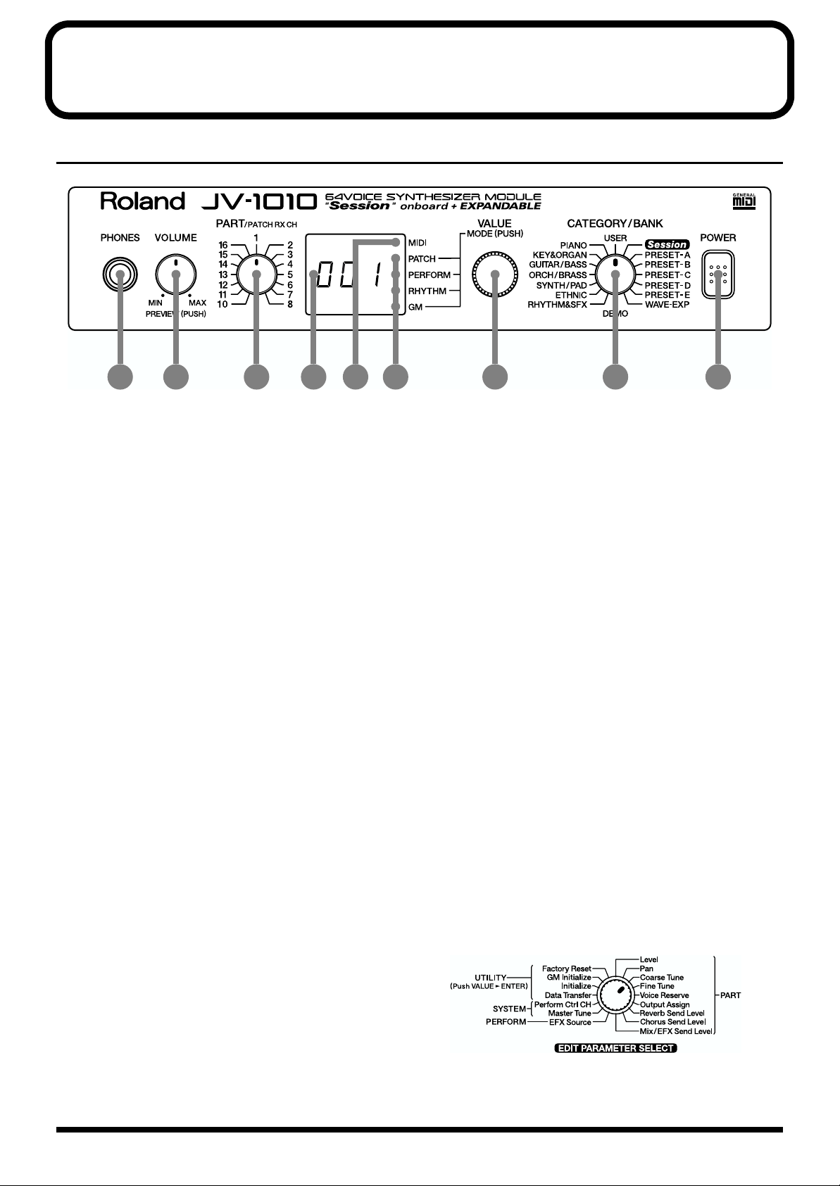
Front Panel
fig.0-01
1
2 3 4 5 6 7 8 9
1. PHONES Jack
This is the jack for connecting headphones (sold separately).
* Use headphones with an impedance of 8 to 150 Ohms.
2. VOLUME Knob
This adjusts the volume level for the OUTPUT jack and the PHONES jack. You can also check out a
sound using the JV-1010 alone by pressing the VOLUME knob (Phrase Preview, p. 25). When in a
mode other than the Patch mode, pressing the VALUE knob while holding down the VOLUME knob
switches you to the Edit mode.
3. PART Knob
In the Patch mode, it changes the receive channel. In the Performance mode or the GM mode, it
selects the Part to which settings are to be applied.
4. Display
Displays a variety of information about the operation being performed.
5. MIDI Indicator
Lights up when MIDI messages are received.
6. MODE Indicators
The indicator for the currently active mode lights up.
7. VALUE Knob
This changes the setting values for parameters. Turning the knob rapidly makes the value change in
larger increments. Pressing the knob switches the mode. When in a mode other than the Patch mode,
pressing the VALUE knob while holding down the VOLUME knob switches you to the Edit mode.
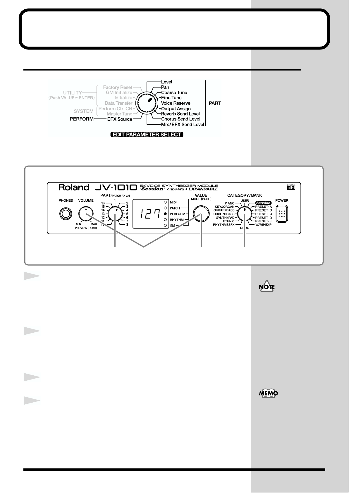
8. CATEGORY/BANK Knob
Used to switch the sound selection range.
In the Edit mode, it is used to select the
parameter to be set. For more information
about the CATEGORY/BANK knob’s functions
in Edit mode, refer to the
SELECT
chart on the JV-1010’s top panel.
EDIT PARAMETER
9. POWER Switch
Pressed to switch the power on and off.
11
Page 12
Front and Rear Panel
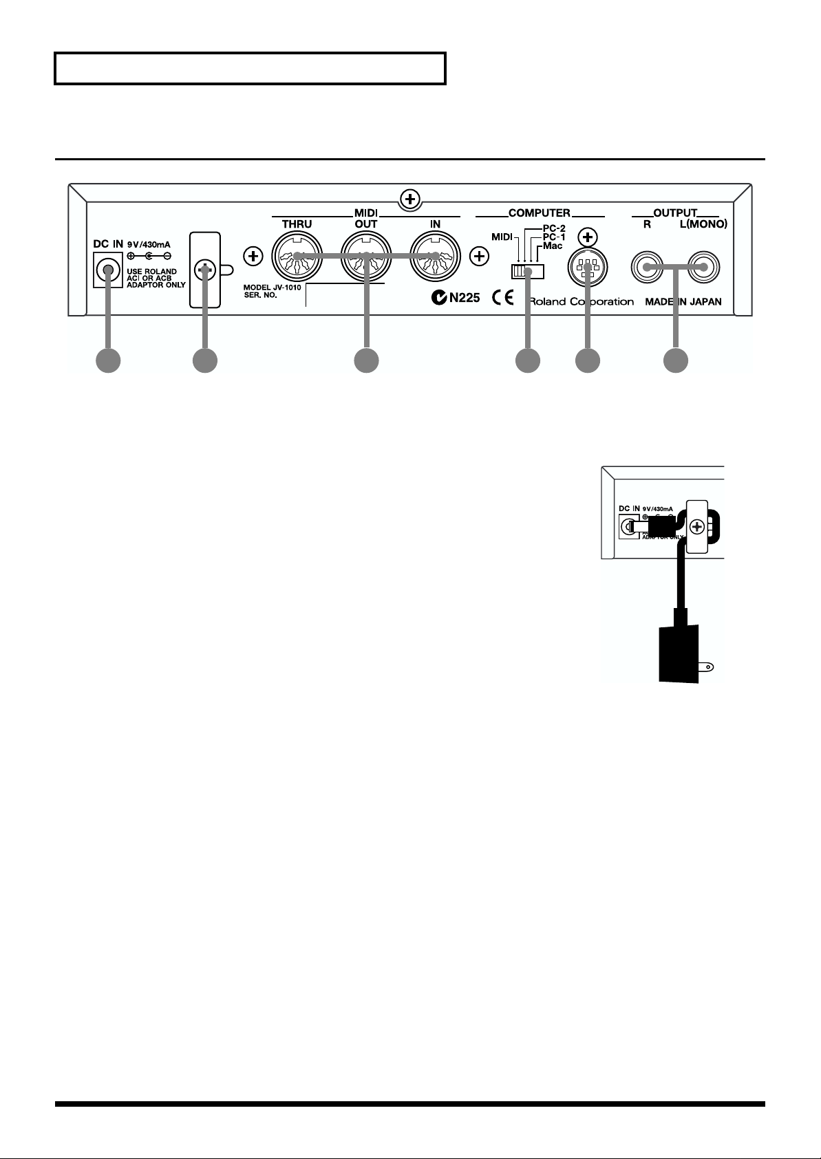
Rear Panel
fig.0-02
1 2 4 53 6
1. AC Adaptor Jack
Accepts connection of the supplied AC adapter.
2. Cord Hook
To prevent the inadvertent disruption of power to your unit (should the
plug be pulled out accidentally), and to avoid applying undue stress to the
AC adaptor jack, anchor the power cord using the cord hook, as shown in
the illustration.
3. MIDI Connectors (IN, OUT, THRU)
These connectors are used to connect the JV-1010 with other devices for sending and receiving MIDI
messages.
When using these connectors to exchange MIDI messages, set the COMPUTER switch to MIDI.
MIDI IN: This receives information from other MIDI instruments.
MIDI OUT: This sends information from the JV-1010.
MIDI THRU: This sends out, unaltered, information received from MIDI IN.
4. COMPUTER Switch (Mac, PC-1, PC-2, MIDI)
The switch should be set as appropriate for the type of computer connected to the COMPUTER
Connector, and the software being used (p. 38).
When using the MIDI connectors, set this to MIDI.
* Turn off the power before changing this switch’s setting.
5. COMPUTER Connector
This is for connecting a computer to the JV-1010 using a computer cable (sold separately) (p. 38).
Set the COMPUTER switch to Mac or PC-2.
6. OUTPUT Jacks (L (MONO), R)
These are for stereo (L/R) output of audio signals to an amp or a mixer. For monaural output,
connect to the left (L) jack.
12
Page 13
Quick Start
Quick Start
13
Page 14
Getting Ready to Play
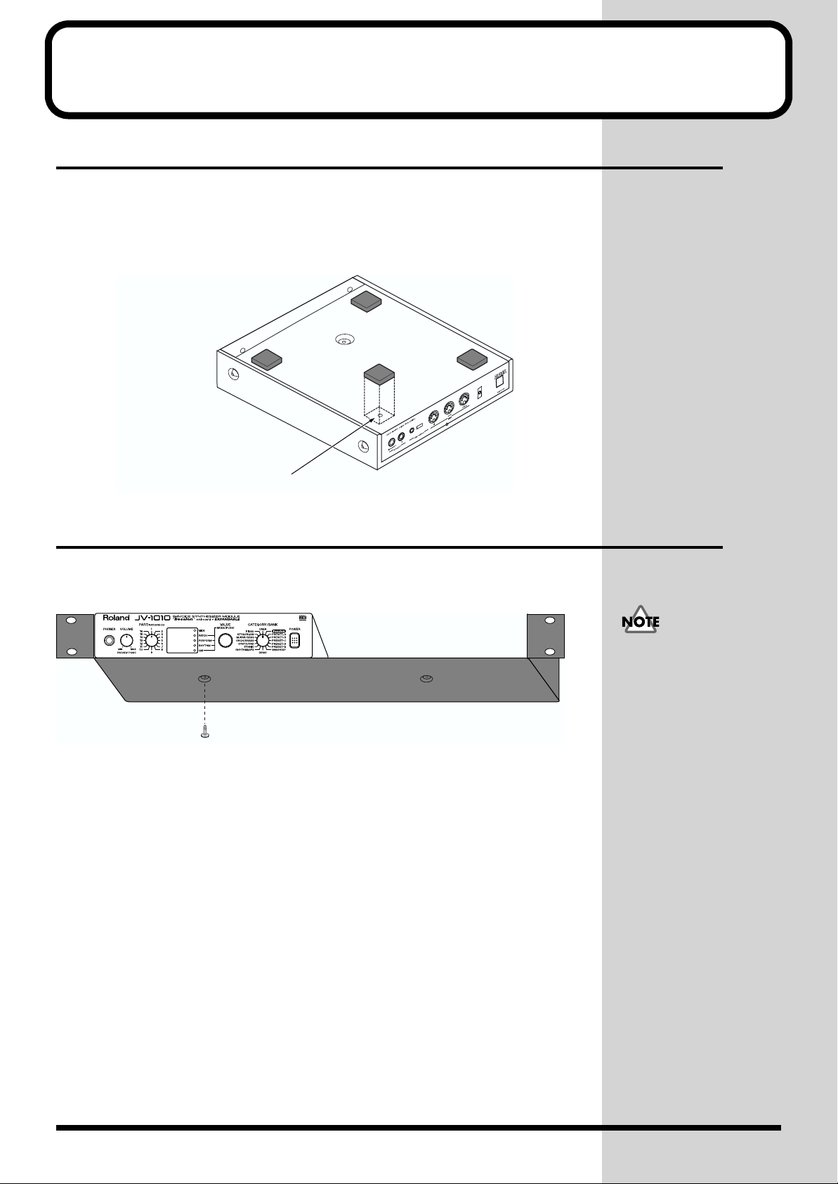
Attaching the Rubber Feet
If you will not be using the separately available RAD-50 rack-mount
adaptor, attach the rubber feet that were supplied with the JV-1010, as
shown in the figure. Use the small holes on the bottom as a guide for
positioning the rubber feet when attaching them.
fig.1-01.e
affix the supplied rubber feet onto the bottom of the unit
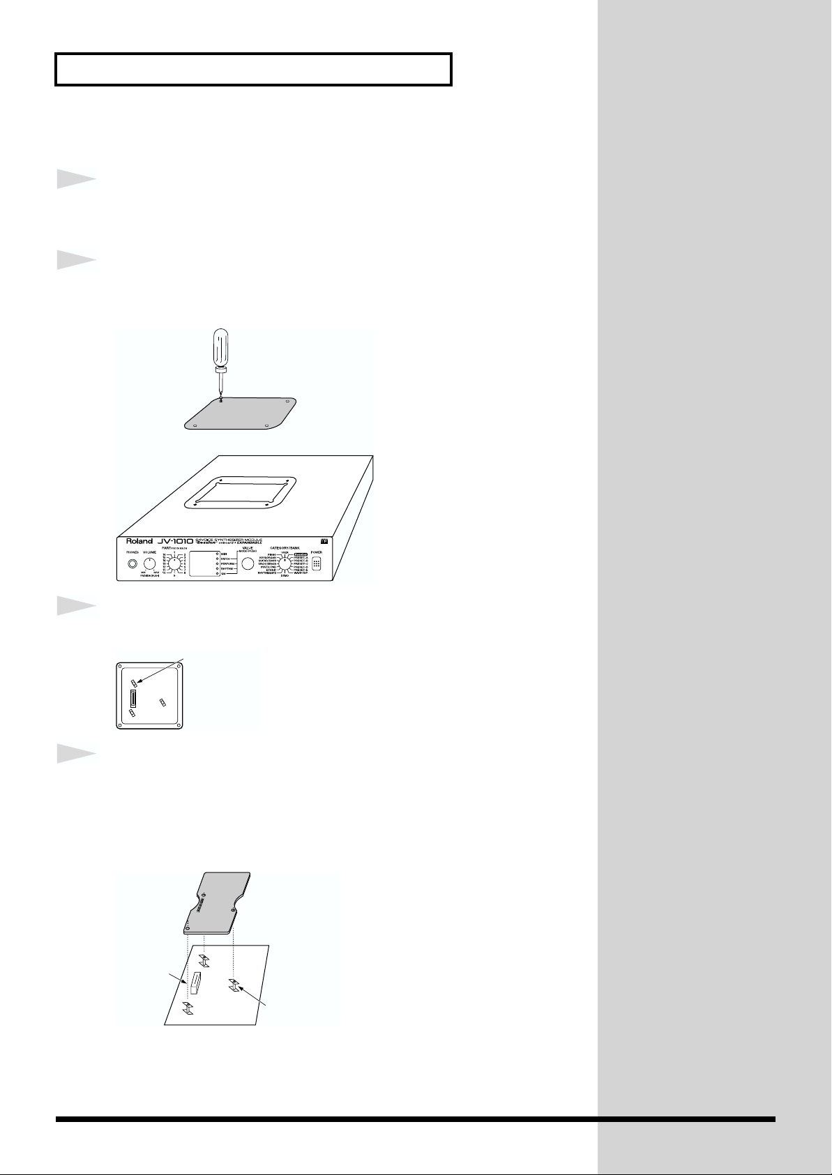
Installing on the Rack-Mount Adaptor
When installing on the rack-mount adaptor (RAD-50; sold separately), use
the screw (M4 x 8) included with the rack-mount adaptor.
fig.1-02.e
Screw (M4 x 8)
When mounting the unit
using the rack-mount
adaptor, install it onto the
rack-mount adaptor
without attaching the
rubber feet.
14
Page 15

Installing a Wave Expansion Board
One Wave Expansion Board (SR-JV80 series; sold separately) can be
installed in the JV-1010.
Waveform data, patches and rhythm sets are stored on the Wave Expansion
Board, so you can increase the number of available sounds by installing the
board in the JV-1010.
The Wave Expansion Board can be installed by removing the top cover.
■ How to Install a Wave Expansion Board
First, here are some important points to remember when installing into the
JV-1010:
● To avoid the risk of damage to internal components that can be caused by
static electricity, please carefully observe the following whenever you
handle the board.
• Before you touch the board, always first grasp a metal object (such as
a water pipe), so you are sure that any static electricity you might
have been carrying has been discharged.
•When handling the board, grasp it only by its edges. Avoid touching
any of the electronic components or connectors.
• Save the bag in which the board was originally shipped, and put the
board back into it whenever you need to store or transport it.
● Do not touch any of the printed circuit pathways or connection terminals.
● Never use excessive force when installing a circuit board. If it doesn’t fit
properly on the first attempt, remove the board and try again.
● When circuit board installation is complete, double-check your work.
● Install only the specified board, and remove only the specified screws.
● Be careful not to cut your hands on the opening for installing the board.
Getting Ready to Play
Installing a Wave
Expansion Board increases
the patches and drum sets
for Parts, but the number of
Parts doesn’t change.
Quick Start
15
Page 16
Getting Ready to Play
Follow the steps below to install the Wave Expansion Board.
1
2
fig.1-03a.e
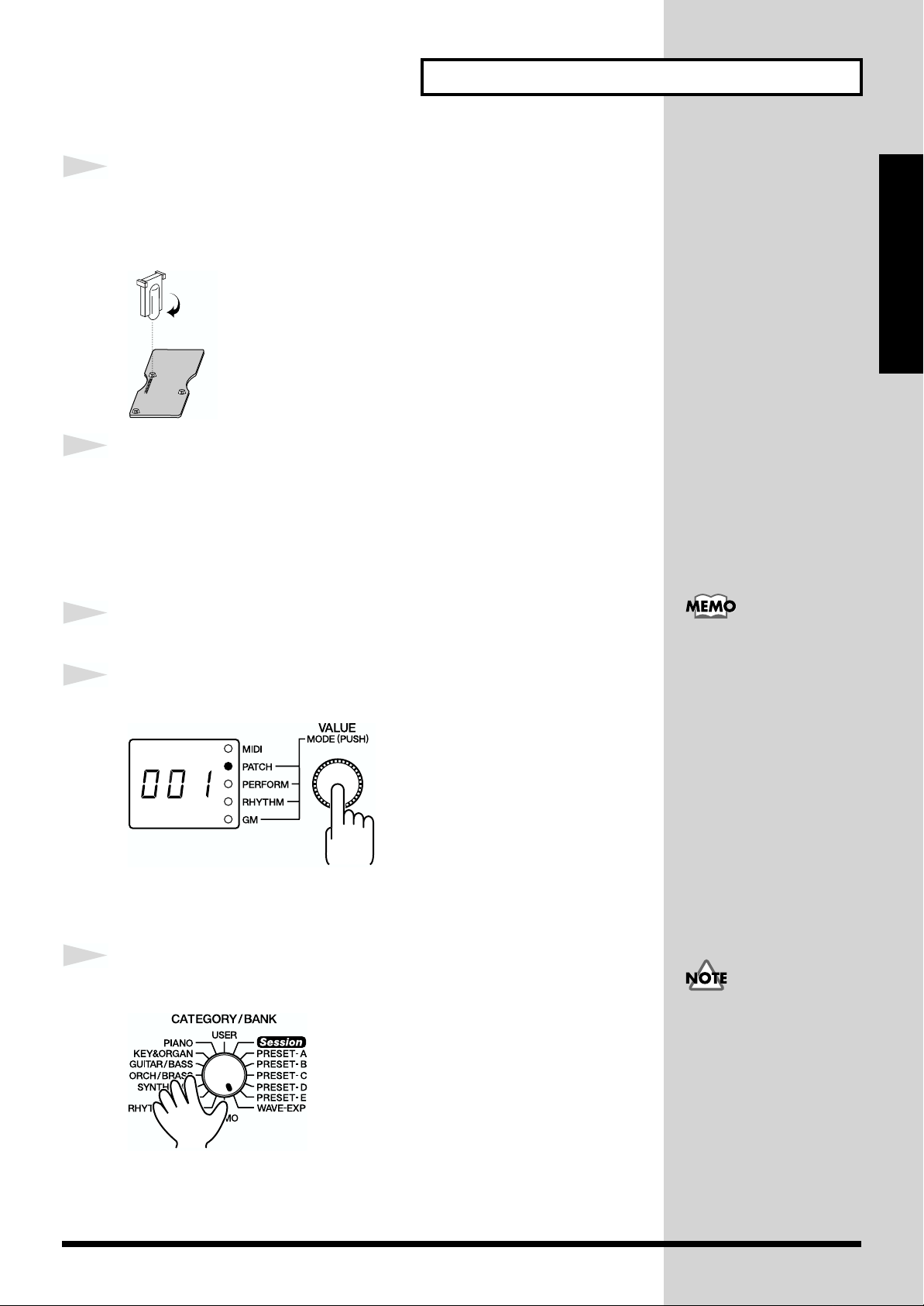
Before installing the Wave Expansion Board, switch off the
power to the JV-1010 and any connected equipment.
Detach the cover on the upper portion of the JV-1010. Loosen
the four screws on the upper portion of the cover.
Screwdriver
3
fig.1-03b.e
4
fig.1-03c.e
Position the board holders so they are oriented.
Board holder
Insert the connector for the Wave Expansion Board into the
connector on the unit, and at the same time, fit the board
holders into the holes. When you do this, the heads of the three
board holders should protrude from the Expansion Board.
Connector
EXP-B
Board holder
16
Page 17
Getting Ready to Play
J
b
5
fig.1-03d.e
6
1
2
fig.1-04
Use the tool supplied with the Wave Expansion Board to
rotate the board holders to LOCK, securing the Wave
Expansion Board in place.
LOCK
Use the (specified) screws you removed in step 2 to reattach
the cover.
This completes the installation of the Wave Expansion Board. Next, make
sure the board is installed correctly.
Switch on the power to the JV-1010 (p. 20).
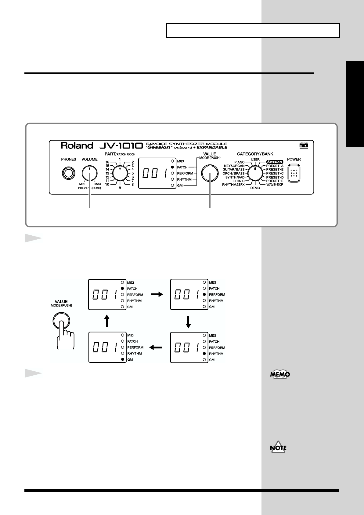
Press the VALUE knob to choose the Patch mode (PATCH).
Pressing the VALUE knob makes the mode change sequentially. Press the
knob several times, until the PATCH indicator lights up.
Quick Start
When a Wave Expansion
Board is installed, then
when you switch on the
power first roland Jv-1010
is displayed, and after that
the final two digits of the
model number for the
installed Wave Expansion
Board flash twice on the
display.
For example, when the SR-
V80-02 “Orchestral” Wave
Expansion Board is
installed, 02 flashes twice
on the display.
3
fig.1-05
Turn the CATEGORY/BANK knob to choose WAVE-EXP.
If 001 appears in the display, the Wave Expansion Board has been installed
correctly.
If the display shows - - -,
it’s likely that the Wave
Expansion Board is not
eing recognized correctly.
Follow the steps in
“Switching Off the
Power” (p. 20) to switch off
the power, then reinstall
the Wave Expansion Board,
making sure you do it
correctly.
17
Page 18
Getting Ready to Play
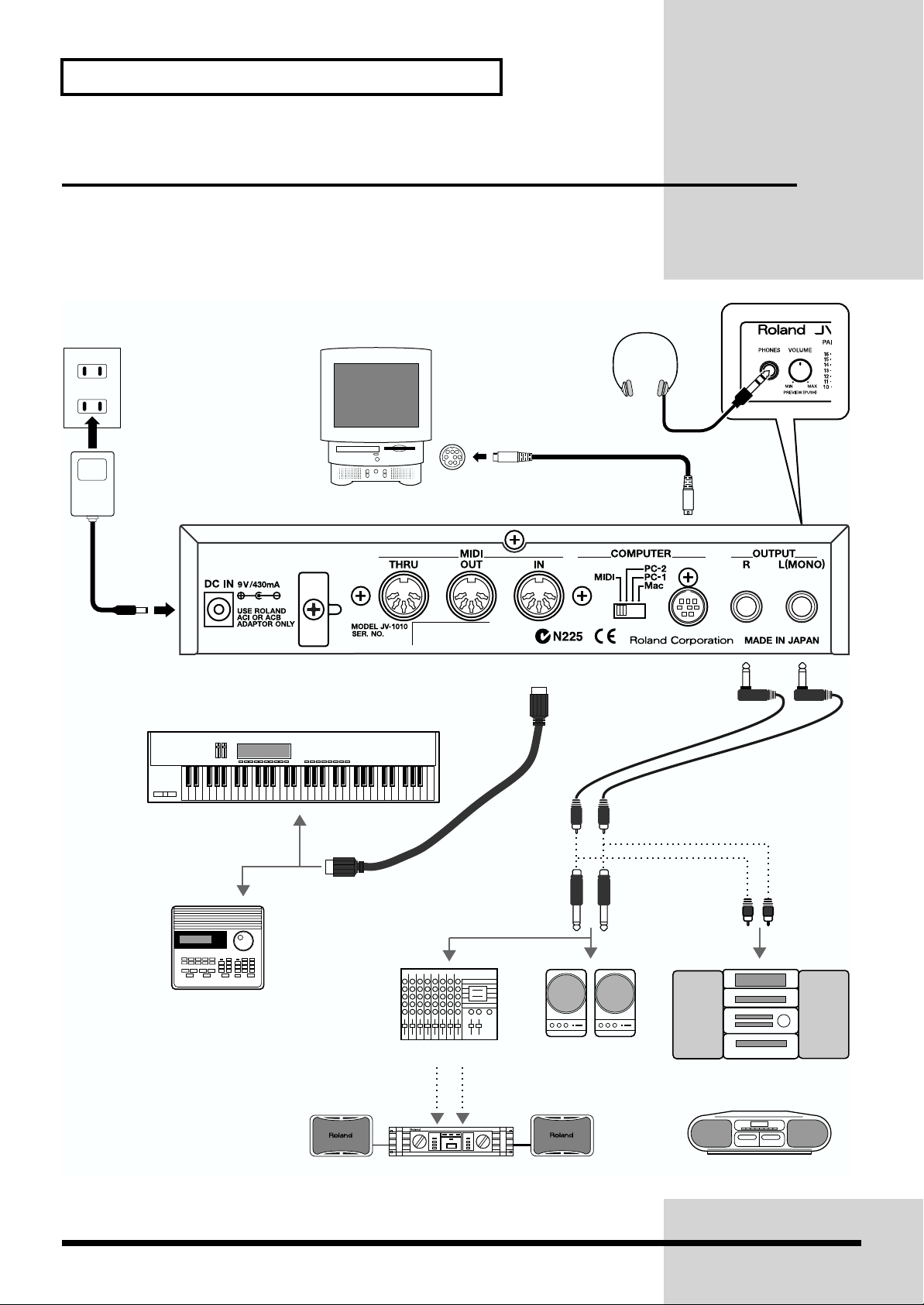
Making the Connections
The JV-1010 does not have a built-in amp or speakers. In order to produce
sound, you need to hook up audio equipment such as a monitor speaker or
a stereo set, or use headphones.
fig.1-06.e
AC adaptor
Headphones
COMPUTER connector
DC IN
MIDI OUT
MIDI sequencer etc.
MIDI keyboard
MIDI OUT
Mixer etc.
MIDI IN
Monitor speakers
(powered)
Stereo set etc.
18
Power amp
Cassette radio
Page 19
1
2
Follow the steps described below to connect the JV-1010 and an external
device.
Before making the connections, make sure the power to all
equipment is switched off.
Connect the included AC adaptor to the AC adaptor jack and
plug the adaptor into a power outlet.
Getting Ready to Play
To prevent malfunction
and/or damage to speakers
or other devices, always
turn down the volume, and
turn off the power on all
devices before making any
connections.
Quick Start
3
Connect the JV-1010 and the external device as shown in the
figure.
Connecting audio equipment: the OUTPUT jacks (L (MONO), R)
Use audio cables (sold separately) to connect the audio device to the
OUTPUT jacks on the JV-1010.
Connecting a MIDI keyboard or sequencer: the MIDI connectors (IN,
OUT, THRU)
Use a MIDI cable (sold separately) to connect the MIDI OUT connector on
the MIDI keyboard or sequencer to the MIDI IN connector on the JV-1010.
Using headphones: the PHONES jack
Plug the headphones (sold separately) into the PHONES jack on the front
panel.
Using a computer: the COMPUTER connector
Use a computer cable (sold separately) to connect the computer to the
COMPUTER connector on the JV-1010.
We recommend using a
stereo connection in order
to get the maximum
performance from the JV1010, but for monaural use,
make the connection to the
L (MONO) OUTPUT jack.
For more information on
making the connection
with the computer, take a
look at “Connecting to a
Computer” (p. 38).
19
Page 20
Getting Ready to Play
b
b
Switching the Power On and Off
■ Switching On the Power
1
2
¬fig.1-07
Before you switch on the power, check the following.
• Are peripheral devices connected correctly?
• Is the volume level on the JV-1010 and the connected external
equipment turned down all the way?
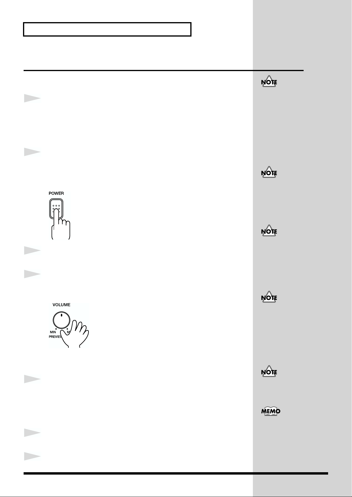
Press the POWER switch on the JV-1010 to switch on the power.
After roland Jv-1010 is displayed, the unit starts up in the same state it was
in when the power was last turned off.
Once the connections have
een completed (p. 18), turn
on power to your various
devices in the order
specified. By turning on
devices in the wrong order,
you risk causing malfunction
and/or damage to speakers
and other devices.
If the power was turned off
while in the Rhythm Set
mode (RHYTHM), the unit
starts up in the Performance
mode (PERFORM).
This unit is equipped with
3
4
Switch on the power to the connected external equipment.
Play sounds on the JV-1010 and turn the VOLUME knob to
a protection circuit. A brief
interval (a few seconds)
after power up is required
efore the unit will operate
normally.
adjust the volume on the JV-1010 and the external equipment.
fig.1-08
Be careful not to turn the
volume up too high.
Excessive volume levels are
not only inconsiderate to
others around you, but may
damage external equipment
or cause hearing loss.
■ Switching Off the Power
1
2
Before you switch off the power, check the following.
• Is the volume level on the JV-1010 and the connected external
equipment turned down all the way?
•Have you saved the sounds or other data you’ve created? (p. 48)
Switch off the power to the connected external equipment.
Turning the VOLUME knob
up all the way may result in
distortion for some sounds.
You can also play sounds
on just the unit itself by
pressing the VOLUME
knob (Phrase Preview, p.
3
20
Switch off the POWER switch on the JV-1010.
Page 21
Reset to Default Factory Settings (Factory Reset)
When using the JV-1010 for the first time, start by returning the settings to
their factory defaults so that the JV-1010 operates as described in the
procedures in the owner’s manual.
This returns all settings stored in memory in the JV-1010 to the values they
had when the unit was shipped from the factory.
fig.1-09
1,4,52 3
Quick Start
fig.Sur
1
2
3
4
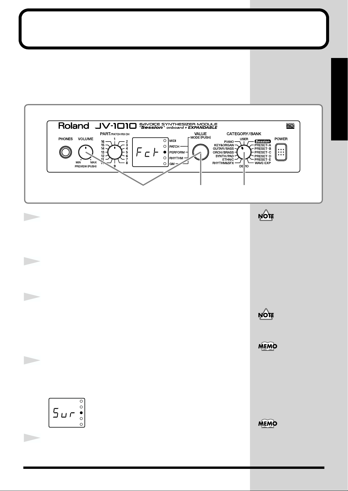
Press the VALUE knob to switch to a mode other than the
Patch mode (PATCH), that is, to the PERFORM, RHYTHM, or
GM mode.
While holding down the VOLUME knob, press the VALUE knob.
Switch to the Edit mode.
Turn the CATEGORY/BANK knob to choose PIANO (Factory
Reset).
Fct flashes on the display.
In the Edit mode, choosing PIANO (Factory Reset) with the CATEGORY/
BANK knob makes it possible to perform Factory Reset.
Press the VALUE knob.
Sur flashes on the display, prompting you to confirm that you indeed wish
to carry out a Factory Reset.
If there is important data
you’ve created that’s stored
in memory, all such data is
discarded, and everything is
returned to the factory
defaults when a Factory Reset
is performed. If important
data is stored in the unit, save
it on an external MIDI device
(p. 48).
When in the Patch mode, you
can’t enter the Edit mode.
For more information
about the CATEGORY/
BANK knob’s other
functions in Edit mode,
refer to the EDIT
PARAMETER SELECT
chart on the JV-1010’s top
panel.
5
Press the VALUE knob.
The Factory Reset is performed, and you leave the Edit mode.
To exit from the Edit mode
without carrying out a
Factory Reset, follow the
same procedure as in step 2.
21
Page 22
Listening to Demo Songs (Demo Play)
The JV-1010 comes with four demonstration songs.
Here’s how to start Demo Play, and listen to the outstanding sounds of the
JV-1010.
Song Name Composer/Copyright
All In Good Time Scott Wilkie © 1999 Scott Wilkie Media (ASCAP)
Guitars Forever Gundy Keller © 1999 Gundy Keller / A-TOWN recordings
Rude99 Hans-Joerg Scheffler © 1999 Hans Scheffler
Overtime Hans-Joerg Scheffler © 1999 Hans Scheffler
fig.1-10
All rights reserved.
Unauthorized use of this
material for purposes other
than private, personal
enjoyment is a violation of
applicable laws.
1
2
3
fig.1-10a
3 2,3 1
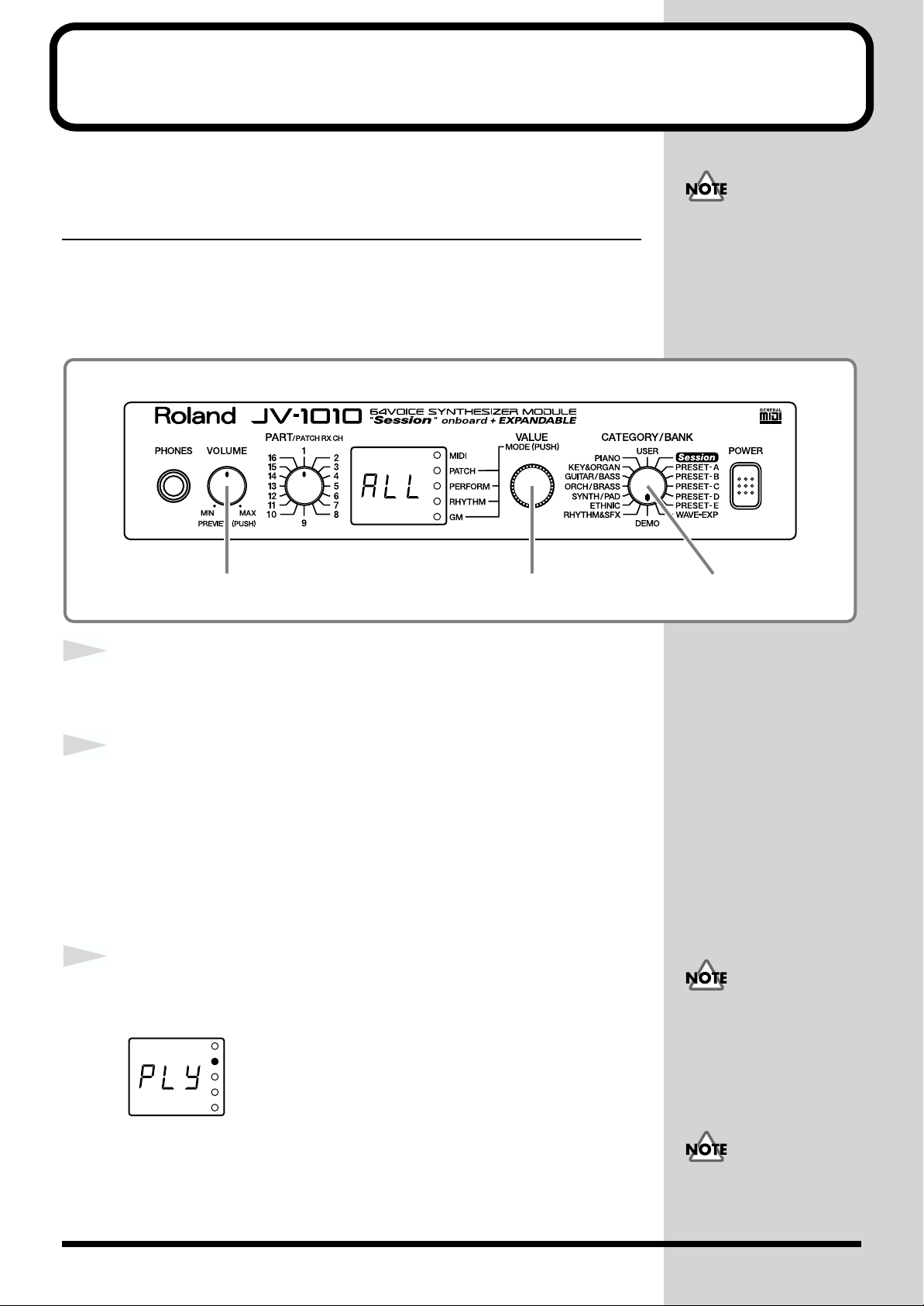
Turn the CATEGORY/BANK knob to choose DEMO.
ALL flashes on the display.
Turn the VALUE knob to choose the song you want to hear.
You can choose ALL, d-1, d-2, d-3, or d-4.
ALL: the songs will playback successively, beginning from the first.
d-1: All In Good Time
d-2: Guitars Forever
d-3: Rude99
d-4: Overtime
Press the VALUE knob or the VOLUME knob.
The display shows Ply and Demo Play starts.
MIDI messages received
from external instruments
are ignored while the
Demo Play screen is
displayed.
22
After a demo song has played all the way to the end, the unit automatically
returns to the start of the song and playback is repeated. To end Demo Play
partway through a song, press the VALUE knob or the VOLUME knob, or
turn the CATEGORY/BANK knob.
No data for the music that
is played will be output
from MIDI OUT.
Page 23

■ Composer Profiles
Scott Wilkie
Scott Wilkie is a contemporary jazz recording artist, based in southern California. He tours frequently
with his own band, and also appears as an artist for Roland in the U.S., Japan, Europe and South
America. His debut solo album, Boundless, was released worldwide in 1999 on Narada/Virgin
Records. You can find him on-line at www.scottwilkie.com.
Gundy Keller
Gundy Keller, a Germany-based guitarist, songwriter and producer, has been an international
demonstrator for Roland since 1986. Gundy focuses mainly on the GR synthesizers and the V-Guitar,
for international music conventions as well as recording sessions requesting completely unusual guitar
sounds. Besides creating his own production company, he’s the founder and director of Rocksound
Music School, a private institute for music instruction. Check out some of his other work on the Roland
VG-8 Demo CD, or the Roland GR-30 Video.
Listening to Demo Songs (Demo Play)
Quick Start
Hans-Joerg Scheffler
Born and raised in the Ruhr valley, the biggest industrial area in Germany, Hans’s attraction to noise
and rhythm came naturally.
Today he runs his own company, DIGITAL AUDIO DESIGN, which produces sampling CDs and CD
ROMs.
He works for Roland as a pro audio product specialist, as a sound designer for expansion boards, and
as a composer of demo songs. He has released several CDs that use the Roland RSS system.
Soundclips of his work can be downloaded at: http://www.united-sound.com/usmaster/
cell2downde.htm
23
Page 24
Choosing and Playing Patches
The JV-1010 comes with a large number of onboard sounds. On the JV-1010,
the sounds used for an ordinary performance are called Patches.
With the JV-1010, you can use seven groups—User, Preset A through E, and
Session—and when a Wave Expansion Board (separately available) is
installed, you can also use the Wave Expansion Board’s onboard patches.
USER
There are 128 patches stored in memory, which you can overwrite with
patches you create yourself.
PRESET-A–C, E
There are 512 patches stored in memory, which cannot be overwritten.
PRESET-D (GM [General MIDI])
These are patches for the General MIDI System, which is designed to
standardize the specifications for MIDI functions for all manufacturers and
models. There are 128 patches stored in memory, which cannot be
overwritten.
When using software for
external MIDI devices, tone
editors, and the like, you
can transmit System
Exclusive messages to
rewrite USER content.
Session
Already onboard is the data from the SR-JV80-09 Wave Expansion Board,
which offers a selection of 255 patches, which cannot be overwritten.
WAVE-EXP (Wave Expansion Board installed in the slot)
Patches are stored in memory on the separately available Wave Expansion
Board, and cannot be overwritten.
You can’t choose a WAVE-
EXP patch unless a Wave
Expansion Board is
installed in the slot EXP-B.
When no Wave Expansion
Board is installed, - - appears on the display.
24
Page 25
Choosing and Playing Patches
Auditioning Patches (Phrase Preview)
On the JV-1010, you can check out patches easily, since phrases are provided
for each type of patch. Thanks to this, you don’t need to have a MIDI
keyboard or sequencer connected.
In this section, we’ll listen to patch sounds in the Patch mode.
fig.1-11
Quick Start
1
fig.1-12
2
2 1
Press the VALUE knob to choose the Patch mode (PATCH).
Pressing the VALUE knob makes the mode change sequentially. Press the
knob several times, until the PATCH indicator lights up.
Holding down the VOLUME knob, the sound for the currently
selected patch is played.
Right after returning
settings to their factory
defaults, the first patch of
the currently selected
Category and Bank
(CATEGORY/BANK) plays.
Some patches may not be
sounded in a suitable range.
25
Page 26

Choosing and Playing Patches
Playing Notes from a MIDI Keyboard
The JV-1010 receives and plays MIDI data from other instruments. When
doing this, the transmitting instrument (the MIDI keyboard or the like) and
the JV-1010 must be set to the same MIDI channel.
Here we’ll play sounds with both channels set to 1.
fig.1-13
1
2
3
4
4 3
Connect a MIDI keyboard to the JV-1010 (p. 18).
Set the transmit channel for the MIDI keyboard (the
transmitting instrument) to 1.
For information on how to make the settings, refer to the owner’s manual
for the MIDI keyboard.
Press the VALUE knob to choose the Patch mode (PATCH).
Pressing the VALUE knob makes the mode change sequentially. Press the
knob several times, until the PATCH indicator lights up.
Turn the PART knob and choose 1.
Here, 1 becomes the JV-1010’s receive channel.
5
fig.1-14
26
Finger some keys on the MIDI keyboard to play a few notes.
When MIDI data is received, the MIDI indicator lights up.
Page 27
Choosing Patches
When you’ve selected the Patch mode or the Performance mode, after
changing the Category and Bank with the CATEGORY/BANK knob, you
can choose a patch by turning the VALUE knob.
You can use either of two methods to choose
a patch: choosing by bank (display with
white text) or choosing by category (display
in blue text).
■ Choosing Patches by Bank
In this section, let’s choose No. 108 Flute from USER (the User group).
fig.1-16
Choosing and Playing Patches
You can’t choose a WAVEEXP patch unless a Wave
Expansion Board is
installed in the slot EXP-B.
When no Wave Expansion
Board is installed, - - appears on the display.
by bankby category
Quick Start
1
2
3
4
fig.1-16a
4 1,3 2
Press the VALUE knob to choose the Patch mode (PATCH).
Pressing the VALUE knob makes the mode change sequentially. Press the
knob several times, until the PATCH indicator lights up.
Turn the CATEGORY/BANK knob to choose USER.
Turn the VALUE knob and choose 108.
You can listen to the selected patch sound (USER No. 108
Flute) by holding down the VOLUME knob.
At this time, the currently selected preset bank USr (USER) and the patch
number 108 appear in alternation on the display.
Turning the VALUE knob
rapidly makes the value
change in large increments.
For more information
about the onboard patches,
take a look at “Patch List”
(p. 54).
27
Page 28
Choosing and Playing Patches
b
j
■ Choosing Patches by Category
Here, let’s choose No. 008 Bright Piano from PIANO (the Piano category).
fig.1-17
4 1,3 2
1
2
3
4
fig.1-18a
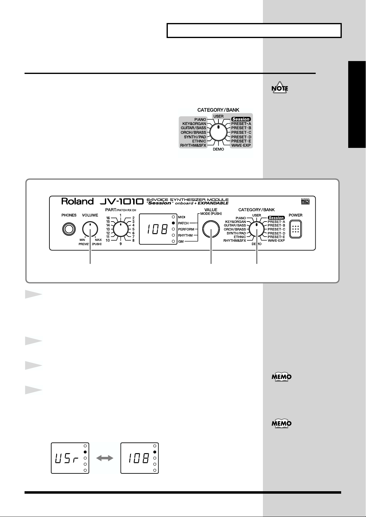
Press the VALUE knob to choose the Patch mode (PATCH).
Pressing the VALUE knob makes the mode change sequentially. Press the
knob several times, until the PATCH indicator lights up.
Turn the CATEGORY/BANK knob to choose PIANO.
Turn the VALUE knob to choose 008.
You can listen to the selected patch sound (PIANO No. 008
Bright Piano) by holding down the VOLUME knob.
At this time, the currently selected bank PrA (PRESET-A) and the patch
number 002 appear in alternation on the display.
When you release the VOLUME knob, the display shows the patch number
008 of the category group PIANO.
The patches you can choose
y category are Preset A, B,
C, D, and E, and Session
(XP-A) patches. The sounds
and categories of User and
WAVE-EXP (XP-B) patches
vary, so you can’t choose
these patches by category.
Turning the VALUE knob
rapidly makes the value
change in large increments.
Also, turning the VALUE
knob while pressing it in
umps you to the value at
the start of each category,
in the currently selected
category group. The start
values for by-category
patches are shown with
a dot at the end of the
number on the display.
For more information
about the by-category
patches, take a look at
“Patch Category List” (p.
58).
28
Page 29
Playing Percussion Sounds
The JV-1010 has Rhythm Sets that contain a variety of percussion
instruments and special effects sounds.
With the JV-1010, you can use seven groups—User, Preset A through E, and
Session—and when a Wave Expansion Board (separately available) is
installed, you can also use the Wave Expansion Board’s onboard rhythm
sets.
USER
There are 2 rhythm sets stored in memory, which you can overwrite with
patches you create yourself.
PRESET-A–C, E
There are 8 rhythm sets stored in memory, which cannot be overwritten.
PRESET-D (GM [General MIDI])
These are rhythm sets for the General MIDI System, which is designed to
standardize the specifications for MIDI functions for all manufacturers and
models. There are 2 rhythm sets stored in memory, which cannot be
overwritten.
Choosing and Playing Patches
Quick Start
When using software for
external MIDI devices, tone
editors, and the like, you
can transmit System
Exclusive messages to
rewrite USER content.
Session
Already onboard is the data from the SR-JV80-09 Wave Expansion Board,
which offers a selection of 8 rhythm sets, which cannot be overwritten.
WAVE-EXP (Wave Expansion Board installed in the slot)
Patches are stored in memory on the separately available Wave Expansion
Board, and cannot be overwritten.
You can’t choose a WAVE-
EXP patch unless a Wave
Expansion Board is
installed in the slot EXP-B.
When no Wave Expansion
Board is installed, - - appears on the display.
29
Page 30

Choosing and Playing Patches
To play rhythm sets using a MIDI keyboard, set the MIDI transmit channel
for the MIDI keyboard to 10.
Here’s how you can play percussion instruments using rhythm sets:
fig.1-19
2,4 3
1
2
3
fig.1-20
Set the transmit channel for the MIDI keyboard (the
transmitting instrument) to 10.
For information on how to make the settings, refer to the owner’s manual
for the MIDI keyboard (the transmitting instrument).
Press the VALUE knob and choose the Rhythm Set mode
(RHYTHM).
Pressing the VALUE knob makes the mode change sequentially. Press the
knob several times until the RHYTHM indicator lights up.
Turn the CATEGORY/BANK knob and choose a bank. Make
your selection from the text displayed in white.
You can’t choose a WAVE-
EXP patch unless a Wave
Expansion Board is
installed in the slot EXP-B.
When no Wave Expansion
Board is installed, - - appears on the display.
4
5
30
Turn the VALUE knob and choose a rhythm set.
Finger some keys on the MIDI keyboard to play a few notes.
A wide variety of percussion sounds are played, depending on the keys you
finger.
When MIDI data is received, the MIDI indicator lights up.
When you’ve selected the
Rhythm Set mode, the
display shows the settings
for Part 10, no matter what
setting the PART knob is at.
For more information
about the onboard rhythm
sets, take a look at
“Rhythm Set List” (p. 64).
Page 31

Using the JV-1010 as the GM Sound Module
The JV-1010 features a GM mode—a convenient way to play back or create
GM score data (music files for GM sound module). You’re able to play back
commercial GM score data releases and even modify various parameter
settings for enhanced musical expression.
Entering GM Mode
fig.1-20a
1
Use GM mode to place the JV-1010’s sound source in GM System compatible
mode. Basically GM mode is similar to a special kind of Performance in
which a GM System Rhythm Set is assigned to Part 10, and GM System
Patches are assigned to other Parts.
1
Press the VALUE knob to switch to the GM mode (GM ).
For more information about
the performance, please refer
to
“Performing Multiple
Parts (Performance
Mode)”
(p. 42).
Quick Start
Pressing the VALUE knob makes the mode change sequentially. Press the
knob several times, until the GM indicator lights up.
When you switch to the GM mode, the sound generator is initialized with
basic settings that allow it to conform with the General MIDI System.
Each time you enter GM mode, the GM Drum Set is assigned to Part 10, and
Piano 1 is assigned to other Parts. You can also select other GM Patches and
GM Drum Sets for each Part to match the performance.
If you want to preserve the
GM mode settings, save the
settings to an external MIDI
device by transmitting them
as MIDI messages. For further
details, see
Settings to an External
MIDI Device (Data
Transfer)”
In GM mode, “- - -”
appears in the display
when a parameter that
cannot be set is selected.
“Transmitting
(p. 48).
31
Page 32

Changing Sounds from an External MIDI Device
You can change patches, performances, and rhythm sets by transmitting Bank
Select messages (Controller numbers 0 and 32) and Program Change messages
to the JV-1010 from an external MIDI device. That is, selecting sounds on an
external MIDI keyboard transmits messages corresponding to the specified
sounds to the JV-1010, thus changing the patch or the like on the JV-1010.
■
Note on Using an External MIDI Device to Switch Sounds
If an external MIDI device transmits a Bank Select message that is outside
the range that the JV-1010 considers as being valid, it is ignored—only the
Program Change message is accepted.
When a JV/XP Series MIDI device is connected to the JV-1010, selecting a
Wave Expansion C (XP-C) or later bank or sound may result in a switch to
a number other than the intended number, so use numbers within the
allowable reception range.
For more on which Bank Select messages can be received, refer to “MIDI
Implementation” (p. 68).
If the Program Numbers on your external MIDI device are referenced as
values from 0 to 127, find the appropriate number by subtracting 1 from the
number in this unit’s correspondence chart. The numbers are displayed in
decimal format.
On the JV-1010, when just a
Program Change message
is received without
receiving a Bank Select
message, only sounds
within a group (such as
PRESET-A or USER) are
changed.
Changing Patches
The JV-1010 can change patches (including the patches for various parts in
a performance) in response to the MIDI data it receives.
Here, we’ll set the transmit channel on the external MIDI device and the
receive channel on the JV-1010 to 1, then transmit a MIDI message from the
external MIDI device to change the patch on the JV-1010 to No. 010 Hip
fig.1-21
Bass in PRESET-B.
3 2
1
32
Set the transmit channel on the external MIDI device to 1.
For information on how to make the settings, refer to the owner’s manual
for the external instrument (the transmitting instrument).
Page 33

Changing Sounds from an External MIDI Device
2
3
4
5
6
Press the VALUE knob to choose the Patch mode (PATCH).
Pressing the VALUE knob makes the mode change sequentially. Press the
knob several times, until the PATCH indicator lights up.
Turn the PART knob and choose 1.
Here, 1 becomes the JV-1010’s receive channel.
Transmit a Bank Select MSB (Controller Number 0) value of 81
from the external MIDI device to the JV-1010
Transmit a Bank Select LSB (Controller Number 32) value of 1
from the external MIDI device to the JV-1010.
Transmit a Program Change 10 from the external MIDI device
to the JV-1010.
Quick Start
Be sure to set the transmit
channel for the external
MIDI device and the
receive channel for the JV1010 to the same channel.
The display on the JV-1010 shows 010 to indicate the switch to the PRESET-
B patch No. 010 Hip Bass.
The correspondences between MIDI messages transmitted from external
MIDI devices and Patch Numbers are as shown below.
Patch Patch Bank Select Program
Group Number MSB LSB Number
USER 1–128 80 0 1–128
PRESET-A 1–128 81 0 1–128
PRESET-B 1–128 81 1 1–128
PRESET-C 1–128 81 2 1–128
PRESET-D 1–128 81 3 1–128
PRESET-E 1–128 81 4 1–128
Session 1–128 84 0 1–128
Session 129–255 84 1 1–127
WAVE-EXP 1–128 84 2 1–128
WAVE-EXP 129–256 84 3 1–128
On the JV-1010, when just a
Program Change message
is received without
receiving a Bank Select
message, only patches and
rhythm sets within the
same group are changed.
33
Page 34

Changing Sounds from an External MIDI Device
Changing a Performance
When changing a performance, set the transmit channel of the external
MIDI device and the Performance Control Channel (Perform Ctrl CH) of the
JV-1010 to the same channel, then transmit the Bank Select and Program
Change messages.
Now let’s set the transmit channel on the external MIDI device and the
Performance Control Channel (Perform Ctrl CH) on the JV-1010 to the same
channel and try changing the performance.
fig.1-22
For more information about
the performance, please refer
to
“Performing Multiple
Parts (Performance
Mode)”
(p. 42).
1
2
3
4
5
Press the VALUE knob and choose the Performance mode
(PERFORM).
Pressing the VALUE knob makes the mode change sequentially. Press the
knob several times until the PERFORM indicator lights up.
While holding down the VOLUME knob, press the VALUE
knob.
Switch to the Edit mode.
Turn the CATEGORY/BANK knob to choose SYNTH/PAD
(Perform Ctrl CH).
Turn the VALUE knob and choose the channel.
A value of from 001 to 016, or OFF flashes in the display.
While holding down the VOLUME knob, press the VALUE
32,5 1,4
When you first take the
unit out of the box, the
setting for the Performance
Control Channel is at OFF.
34
knob.
The JV-1010 exits Edit mode.
Page 35

Changing Sounds from an External MIDI Device
6
7
8
9
Set the transmit channel on the external MIDI device to the
same value that you selected for the Performance Control
Channel (Perform Ctrl CH) in step 4.
For information on how to make the settings, refer to the owner’s manual
for the MIDI keyboard (the transmitting instrument).
Quick Start
Transmit a Bank Select MSB (Controller Number 0) value
(refer to the following table) from the external MIDI device to
the JV-1010.
Transmit a Bank Select LSB (Controller Number 32) value
(refer to the following table) from the external MIDI device to
the JV-1010.
Transmit a Program Change message from the external MIDI
device to the JV-1010 (refer to the following table).
The correspondences between MIDI messages transmitted from external
MIDI devices and Performance Numbers are as shown below.
Performance Performance Bank Select Program
Group Number MSB LSB Number
USER 1–32 80 0 1–32
PRESET-A 1–32 81 0 1–32
PRESET-B 1–32 81 1 1–32
When changing patches or
rhythm sets in various
parts of a performance, set
the transmit channel of the
external device and the
receive channel of the part
to the same channel. Note
that when the Performance
Control Channel and the
receive channel for the part
are the same, the setting for
the Performance Control
Channel takes priority, and
the performance is
switched.
35
Page 36

Changing Sounds from an External MIDI Device
Changing a Rhythm Set
When changing a rhythm set, set the transmit channel of the external MIDI
device and the receive channel of part 10 of the performance on the JV-1010
to the same channel, then transmit the Bank Select and Program Change
messages.
Now let’s try changing the rhythm set from the external MIDI device.
fig.1-23
1
2
3
4
1
Press the VALUE knob and choose the Performance mode
(PERFORM) or the Rhythm Set mode (RHYTHM).
Pressing the VALUE knob makes the mode change sequentially. Press the
knob several times until the PERFORM or RHYTHM indicator lights up.
Set the transmit channel on the external MIDI device to 10.
For information on how to make the settings, refer to the owner’s manual
for the MIDI keyboard (the transmitting instrument).
Transmit a Bank Select MSB (Controller Number 0) value
(refer to the following table) from the external MIDI device to
the JV-1010.
Transmit a Bank Select LSB (Controller Number 32) value
When you first take the
unit out of the box, the
receive-channel setting for
Part 10 is 10. For more
information about part
receive-channel settings,
check out Reference
Manual that is on the
included CD-ROM.
36
(refer to the following table) from the external MIDI device to
the JV-1010.
Page 37

Changing Sounds from an External MIDI Device
5
Transmit a Program Change message from the external MIDI
device to the JV-1010 (refer to the following table).
The correspondences between MIDI messages transmitted from external
MIDI devices and Rhythm Set Numbers are as shown below.
Rhythm Set Rhythm Set Bank Select Program
Group Number MSB LSB Number
USER 1, 2 80 0 1, 2
PRESET-A 1, 2 81 0 1, 2
PRESET-B 1, 2 81 1 1, 2
PRESET-C 1, 2 81 2 1, 2
PRESET-D 1, 2 81 3 1, 2
PRESET-E 1, 2 81 4 1, 2
Session 1–8 84 0 1–8
WAVE-EXP 1–128 84 2 1–128
WAVE-EXP 129–256 84 3 1–128
Quick Start
37
Page 38

Trying Out Desktop Music
If you are running music software on your computer, you can use the
computer to control the operation of the JV-1010. Of course, this allows you
to play back and create song data, switch sounds automatically, and create
sounds from the screen. This type of system is know as DTM (desktop
music). The actual DTM functions available vary greatly with the
application used. Therefore, it is very important to select software that
matches your particular aims.
Connecting to a Computer
Two Ways to Connect
There are two methods that can be used to connect the JV-1010 to a
computer, connecting to the COMPUTER connector and connecting
with MIDI connectors.
When connecting to the COMPUTER connector, a computer cable is used to
connect the JV-1010 to your computer’s serial port (RS-232C).
When using MIDI connectors to make the connection, a MIDI interface
(such as Roland’s Super MPU64) is required. In this case, the MIDI interface
is connected to the computer, and a MIDI cable is used to connect the MIDI
connectors of the MIDI interface to the JV-1010’s MIDI connectors.
Use the connection method that best suits your operating environment to
connect the JV-1010 to your computer.
If connecting using the MIDI connectors, please read the related information
starting on p. 41.
■ Connecting to the COMPUTER Connector
1
Switch off the power to the JV-1010, the computer, and any
connected equipment.
To prevent malfunction
and/or damage to speakers
or other devices, always
turn down the volume, and
turn off the power on all
devices before making any
connections.
38
Page 39

Trying Out Desktop Music
J
b
b
2
fig.1-24.e
3a
3b
Set the COMPUTER switch on the JV-1010’s rear panel to
match the type of computer to be connected as described
below.
For Apple Macintosh computers: Mac
For PCs: PC-2
Apple Macintosh
The connection method described in the following step varies according to
the type of computer; read the applicable section (3a or 3b).
PC
For PCs
When using a PC, connect the computer cable to the serial port (RS-232C
connector) found on the computer’s rear panel.
Computer cable (sold separately): RSC-15AT
This cable has a nine-pin connector. If a cable with 25-pin connectors is
required, refer to the “Computer Cable Wiring Diagrams” (p. 90) and
obtain the appropriate cable.
For Apple Macintosh Computers
Before changing the
COMPUTER switch
setting, first switch off the
power to the JV-1010.
Quick Start
As this setting determines
the rate at which data is
transferred between the
computer and the JV-1010
(baud rate), it is necessary
that both the computer and
V-1010 settings match.
This setting determines the
aud rate for the JV-1010.
When setting your
computer, it may be
necessary to make settings
in the software as well. If
you are using Windows,
the driver setting may
differ from that described
in Step 2. In such cases,
carefully read the manual
included with the driver,
and then make the
necessary settings.
When connecting to a Macintosh computer, connect the computer cable to
either the modem port or the printer port on the computer’s rear panel.
Computer cable (sold separately): RSC-15APL
The PC-2 baud rate is 38.4
(kbit/sec), and the PC-1
aud rate is 31.25 (kbit/sec).
39
Page 40

Trying Out Desktop Music
b
4
fig.1-25.e
Connect the other end of the computer cable to the JV-1010’s
COMPUTER connector.
Apple Macintosh
Modem Port or
Printer Port
JV-1010 rear panel
PC
Optional computer cable
RSC-15APL
Serial port (|O|O|)
Optional computer cable
RSC-15AT
Playing back sounds from
the JV-1010 requires that
the AC adaptor be plugged
in and connection of either
audio cables or
headphones. If these
connections have not yet
een made, please refer to
“Making the
Connections” (p. 18). If
the connections are
complete, please see
“Switching On the
Power” (p. 20).
40
Page 41

■ Connecting with MIDI Connectors
Trying Out Desktop Music
1
2
fig.1-26
3
If you have a MIDI interface (such as Roland’s Super MPU64) connected to
your computer or are connecting to a MIDI interface adaptor, you can then
connect using the MIDI connectors.
Switch off the power to the JV-1010, the computer, and any
connected equipment.
Set the COMPUTER switch on the JV-1010’s rear panel to MIDI.
Use a MIDI cable to connect the MIDI OUT connector of the
MIDI interface with the JV-1010’s MIDI IN connector.
For instructions on
connecting to a computer
using a MIDI interface,
refer to the owner’s manual
that was supplied with the
MIDI interface.
Quick Start
To prevent malfunction
and/or damage to speakers
or other devices, always
turn down the volume, and
turn off the power on all
devices before making any
connections.
Before changing the
COMPUTER switch
setting, first switch off the
power to the JV-1010.
4
Use a MIDI cable to connect the MIDI IN connector of the
MIDI interface with the JV-1010’s MIDI OUT connector.
fig.1-27.e
Apple Macintosh
PC
Modem or
Printer Port
MIDI interface adaptor
Super MPU64
MIDI
JV-1010 rear panel
T
U
O
IN
The setting
is MIDI
JV-1010 rear panel
USB
Connector
USB
cable
The setting
is MIDI
41
Page 42

Trying Out Desktop Music
Performing Multiple Parts (Performance Mode)
A group of sixteen parts to which fifteen patches and one rhythm set are
assigned (fixed at Part 10) is collectively referred to as a Performance.
fig.1-28.e
Performance
Part 11
Part 10
Rhythm Set
Part 9
Part 1
Patch
Part 16
Patch
In a performance, you can assign each patch and rhythm set to a part, then
combine these parts to enjoy an ensemble performance. One of the sixteen
parts (Part 10) is reserved for the rhythm set, with patches assigned to the
remaining fifteen parts.
In other words, using performances allows you to control sixteen separate
sounds with one JV-1010.
A sound generator of this type which can control multiple sounds using one
device is referred to as a multitimbral sound generator.
fig.1-29
In the relationship between performances and parts, the performance is like
an orchestra, parts are the performers, and patches and the rhythm set are
the instruments.
Let’s try selecting some parts and sounds, then play the multiple parts
together as a performance.
As one example, select one of the sixteen parts, PART 2, then select the patch
No.008 Gtr Strings in GUITAR/BASS (the GUITAR/BASS group).
42 1,5
42
Page 43

Trying Out Desktop Music
J
1
2
3
4
5
6
Press the VALUE knob to choose the Performance mode
(PERFORM).
Pressing the VALUE knob makes the mode change sequentially. Press the
knob several times, until the PERFORM indicator lights up.
Turn the PART knob and choose 2.
Set the transmit channel of the external device (the
transmitting device) to 2.
For information on how to make the settings, refer to the owner’s manual
for the MIDI keyboard (the transmitting instrument).
Turn the CATEGORY/BANK knob to choose GUITAR/BASS.
Now, select the patch category.
Turn the VALUE knob to choose patch 008.
Now, patch No.008 Gtr Strings in the GUITAR/BASS category is selected
for PART 2.
Repeat Steps 2–5, using the same procedure to select other
Quick Start
Always make sure that the
number selected with the
V-1010’s PART knob
matches the transmit
channel of the external
device (the transmitting
device). Additionally,
remember that PART 10 is
used exclusively by the
rhythm set.
Turning off the JV-1010’s
power without saving the
created data results in the
loss of that data. Save any
important data that you
wish to preserve to an
external MIDI device (p.
parts.
7
Using a sequencer or computer, play back the song.
For instructions on how to play back songs, refer to the owner’s manual for
the external device (the transmitting device).
The Performance Control
Channel (Perform Ctrl CH)
is preset at the factory to
OFF; remember that
patches are switched when
program changes are
recorded in a song. To
release the Performance
Control Channel (Perform
Ctrl CH) OFF setting, set to
something other than OFF
(p. 49).
For more information about
the onboard patches, take a
look at
“Performance
List”
(p. 67).
43
Page 44
Editing Using Only the JV-1010
Making Part Settings (PART)
fig.1-30
Now try changing the level setting (Level) for PART 2 in Performance
mode.
fig.1-30a
1
2
3
4
Press the VALUE knob to choose the Performance mode
(PERFORM).
Pressing the VALUE knob makes the mode change sequentially. Press the
knob several times, until the PERFORM indicator lights up.
While holding down the VOLUME knob, press the VALUE
knob.
Switch to the Edit mode.
Turn the CATEGORY/BANK knob to choose USER (Level).
Turn the PART knob and choose 2.
In Edit mode, you can select USER (Level) with the CATEGORY/BANK
knob to change the volume level setting for each part.
32,6 1,54
When in the Patch mode,
you can’t enter the Edit
mode.
For more information
about the CATEGORY/
BANK knob’s other
functions in Edit mode,
refer to the EDIT
PARAMETER SELECT
chart on the JV-1010’s top
panel.
44
Page 45

Editing Using Only the JV-1010
5
Turn the VALUE knob to change the level. This can be set in
the range 000–127.
Pan, Coarse Tune, and other parameters can be set in the same way. For
more detailed information about each parameter and its settings, refer to the
Reference Manual that is on the included CD-ROM.
6
While holding down the VOLUME knob, press the VALUE
knob.
The JV-1010 exits Edit mode.
Memory-Related Operations (UTILITY)
Turning off the JV-1010’s
power without saving the
created data results in the
loss of that data. Save any
important data that you
wish to preserve to an
external MIDI device (p.
48).
Quick Start
These operations include initialization of data such as the JV-1010 internal
sound data, and transmission of settings to external devices.
fig.1-31
■ Restoring the Factory Settings (Factory Reset)
This operation restores all settings stored in the JV-1010 to their condition at
the time the unit was shipped from the factory.
For more detailed information and instructions for this procedure, refer to
the “Reset to Default Factory Settings (Factory Reset)” (p. 21).
45
Page 46
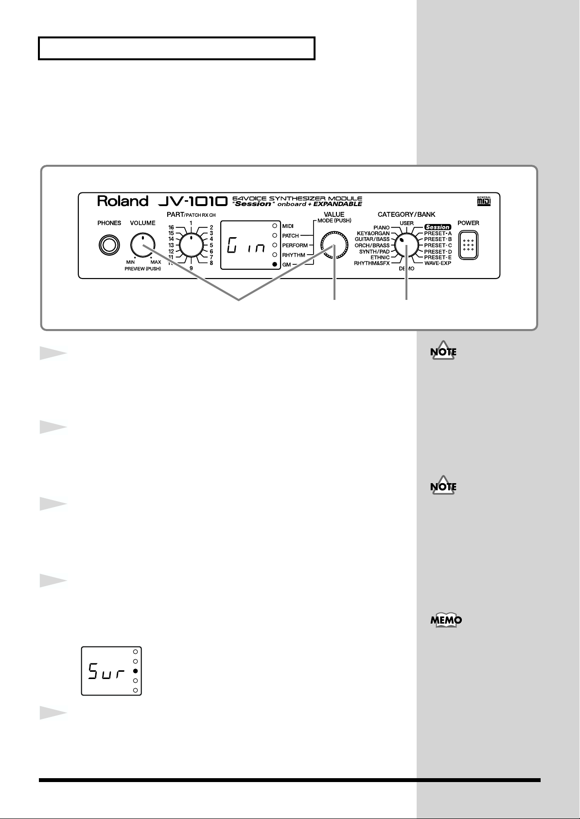
Editing Using Only the JV-1010
■ Initializing GM Mode (GM Initialize)
Using a computer or sequencer connected to the JV-1010 to play music data
bearing the GM logo requires the system be initialized for GM. Carrying out
this initialization restores the basic GM settings.
fig.1-32
32 1,4,5
1
2
3
4
fig.Sur(GM)
Press the VALUE knob to switch to the GM mode (GM).
Pressing the VALUE knob makes the mode change sequentially. Press the
knob several times, until the GM indicator lights up.
While holding down the VOLUME knob, press the VALUE
knob.
Switch to the Edit mode.
Turn the CATEGORY/BANK knob to choose KEY&ORGAN
(GM Initialize).
Gin flashes on the display.
Press the VALUE knob.
Sur flashes in the display; this is a prompt for you to confirm whether or not
you want to execute GM Initialize.
The GM Initialize operation
affects only GM mode data;
no data stored in the user
memory is initialized. If
you want to restore all
settings to their factory
values, carry out Factory
Reset (p. 21).
When in the Patch mode,
you can’t enter the Edit
mode.
To exit Edit mode without
executing GM Initialize,
carry out the operation
described in Step 2.
5
46
Press the VALUE knob.
GM Initialize is executed, and the JV-1010 exits Edit mode.
Page 47
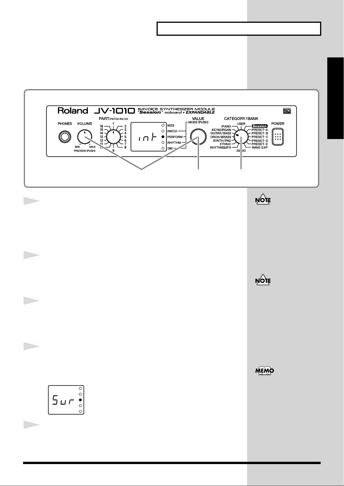
■ Initializing the Settings (Initialize)
This restores the currently selected performance and rhythm set to standard
settings.
fig.1-33
Editing Using Only the JV-1010
Quick Start
32 1,4,5
1
2
3
4
fig.Sur
Press the VALUE knob and choose the Performance mode
(PERFORM) or the Rhythm Set mode (RHYTHM).
Pressing the VALUE knob makes the mode change sequentially. Press the
knob several times until the PERFORM or RHYTHM indicator lights up.
While holding down the VOLUME knob, press the VALUE
knob.
Switch to the Edit mode.
Turn the CATEGORY/BANK knob to choose GUITAR/BASS
(Initialize).
int flashes on the display.
Press the VALUE knob.
Sur flashes in the display; this is a prompt for you to confirm whether or not
you want to execute Initialize.
The GM Initialize operation
affects only the currently
selected data; no data
stored in the user memory
is initialized. If you want to
restore all settings to their
factory values, carry out
Factory Reset (p. 21).
When in the Patch mode,
you can’t enter the Edit
mode.
To exit Edit mode without
executing Initialize, carry
out the operation described
in Step 2.
5
Press the VALUE knob.
Initialize is executed, and the JV-1010 exits Edit mode.
47
Page 48

Editing Using Only the JV-1010
■ Transmitting Settings to an External MIDI Device
(Data Transfer)
This transmits Performance settings to an external MIDI device. This is useful for
times such as when you want to save data on a MIDI instrument ahead of time.
Connect the JV-1010’s MIDI OUT connector to the MIDI IN connector of the
external MIDI device with a MIDI cable. Then, after putting the external
MIDI device in the mode where it is ready to receive data, start the procedure.
fig.1-34
Patch parameters and
system parameters are not
included.
fig.Sur
1
2
3
4
32 1,4,5
Press the VALUE knob to switch to a mode other than the
Patch mode (PATCH), that is, to the PERFORM, RHYTHM, or
GM mode.
While holding down the VOLUME knob, press the VALUE knob.
Switch to the Edit mode.
Turn the CATEGORY/BANK knob to choose ORCH/BRASS
(Data Transfer).
dtr flashes on the display.
Press the VALUE knob.
Sur flashes on the display, prompting you to confirm that you want to carry
out the Data Transfer.
When in the Patch mode,
you can’t enter the Edit
mode.
Transmit GM mode
settings while in GM mode.
GM mode settings are lost
when you switch to
another mode.
To exit Edit mode without
executing Data Transfer,
carry out the operation
described in Step 2.
5
48
Press the VALUE knob.
The Data Transfer is performed, and the JV-1010 exits Edit mode.
Page 49

Editing Using Only the JV-1010
Making System Settings (SYSTEM)
This sets the tuning and other parameters of the JV-1010’s operating
environment.
fig.1-35
■ Selecting the Receive Channel (Perform Ctrl CH)
This selects the receive channel when MIDI messages are used to switch
performances.
fig.1-35a
Quick Start
1
2
3
4
5
32,5 1,4
Press the VALUE knob and choose the Performance mode
(PERFORM) or the Rhythm Set mode (RHYTHM).
Pressing the VALUE knob makes the mode change sequentially. Press the
knob several times until the PERFORM or RHYTHM indicator lights up.
While holding down the VOLUME knob, press the VALUE knob.
Switch to the Edit mode.
Turn the CATEGORY/BANK knob to choose SYNTH/PAD
(Perform Ctrl CH).
Turn the VALUE knob to select the channel.
The value 001–016, OFF flashes in the display.
While holding down the VOLUME knob, press the VALUE knob.
The JV-1010 exits Edit mode.
When in the Patch mode,
you can’t enter the Edit
mode.
For more detailed
information, refer to the
Reference Manual that is
on the included CD-ROM.
49
Page 50

Editing Using Only the JV-1010
■ Tuning (Master Tune)
Allows the sound generator to be tuned. The value indicated is the
frequency of Note Number 69 (the A4 key).
fig.1-36
32,5 1,4
1
2
3
4
5
Press the VALUE knob to switch to a mode other than the
Patch mode (PATCH), that is, to the PERFORM, RHYTHM, or
GM mode.
While holding down the VOLUME knob, press the VALUE
knob.
Switch to the Edit mode.
Turn the CATEGORY/BANK knob to choose ETHNIC
(Master Tune).
Turn the VALUE knob to adjust the tuning frequency.
The value 27.4–52.6 is indicated in the display.
While holding down the VOLUME knob, press the VALUE
When in the Patch mode,
you can’t enter the Edit
mode.
The hundreds place (4) is
not displayed.
50
knob.
The JV-1010 exits Edit mode.
For more detailed
information, refer to the
Reference Manual that is
on the included CD-ROM.
Page 51

Appendices
Appendices
51
Page 52

Troubleshooting
If no sound is produced, or if operation otherwise seems
wrong, first check the following points. If after trying the
following remedies, the unit still does not operate correctly,
please contact your Roland dealer or the nearest Roland
Service Center.
* Refer to the “Error Messages” (p. 53) if some kind of message
is displayed on the screen during operation.
The power does not come on.
- Is the AC adaptor properly plugged onto the wall and the
JV-1010?
No sound is produced.
- Is all other equipment, such as external amps and
speakers, properly connected?
- Is the power to the JV-1010 and all connected external
devices turned on?
- Is the JV-1010’s VOLUME knob turned to MIN?
- Is the volume on any connected external devices turned
down?
- Has the volume been lowered by volume/expression
messages received from an external device?
- Have all connections been made properly?
When using the JV-1010 without a computer, please connect
audio cables or headphones (p. 18).
If using the JV-1010 connected to a computer, use a computer
cable or MIDI cable to make the connection to the computer
(p. 38). Then connect audio cables or headphones (p. 18).
- Is the sound audible with headphones connected?
If sound can be heard through the headphones, then the
cause may lie elsewhere, such as a short in an audio cable
carrying the signal to another device, a bad connection, or a
malfunction in a connected amp, mixer, or speakers.
- Is the specified Wave Expansion Board properly installed?
(p. 15)
WAVE-EXP patches and rhythm sets cannot be selected
unless the Wave Expansion Board is installed in the
designated slot.
- Is the COMPUTER switch on the JV-1010’s rear panel set
to the correct position?
When using the JV-1010 while connected to a computer, set the
switch to the position appropriate for the connection method,
type of computer being used, and the driver settings (p. 38).
* Before changing the COMPUTER switch setting, first switch
off the power to the JV-1010.
Songs are not played back correctly.
- Are you playing songs created for the GS format?
While the JV-1010 is compatible with the General MIDI
System, GS Format is not supported, so such songs may not
play back correctly.
- If playing back GM scores, is the sound generator in GM
mode?
Switch to GM mode (p. 31).
No sound is produced, even when
playing back songs.
- Is the Rx Switch parameter set to OFF?
Set this to ON.
There is no sound for a specific part.
- Is the volume level for the part turned down?
Raise the volume for the part for which no sound is being
produced with the Level setting (p. 44).
- Is reception of MIDI messages enabled?
Set the Rx Switch parameter to ON.
- Does the part’s MIDI receive channel match the MIDI
transmit channel of the connected MIDI device?
Set the MIDI receive channel with the Channel parameter.
The sound is distorted.
- Is a distortion-type effect being applied to the sound?
If the sound for a specific patch or part is distorted, lower the
volume level on that part (p. 44).
When the overall sound is distorted, lower the volume level
with the VOLUME knob.
The pitch has shifted.
- Has the JV-1010’s tuning been shifted?
Check the Master Tune value (p. 50).
- Have the Coarse Tune and Fine Tune settings for the
specific parts been made?
Check the values for the Coarse Tune and Fine Tune
settings (p. 44).
The JV-1010 does not output MIDI
data.
- Is the COMPUTER switch on the JV-1010’s rear panel set
correctly?
When outputting JV-1010 data through the COMPUTER
connector, set the COMPUTER switch to PC-2 or Mac
according to the computer and software being used (p. 38).
The JV-1010 does not output data from the COMPUTER
connector when the COMPUTER switch is set to MIDI. In this
case, data is output from the MIDI OUT connector.
The sound is interrupted.
- Is the polyphony (maximum number of voices) being
exceeded?
When more than 64 voices are used simultaneously, the
voices exceeding this limit of 64 are interrupted.
Set a sufficiently high value as the Voice Reserve setting for
parts you want to make sure are not interrupted (p. 44).
52
Page 53
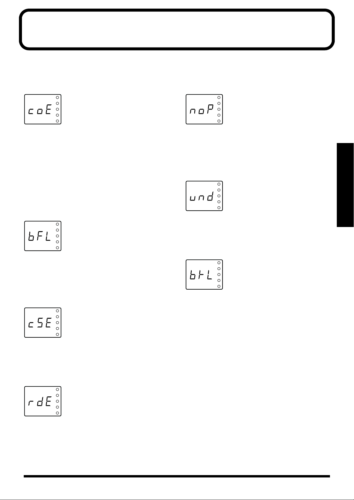
Error Messages
An error message appears in the display when an error in operation occurs, or if an operation cannot be processed correctly.
When this occurs, continue by following the instructions indicated in the error message.
coE (MIDI Communication Error)
fig.coE
Situation: There is a problem with the MIDI cable
connected to the JV-1010’s MIDI IN connector or
with an external device. However, this message
is also displayed when the power for the
external device is turned off.
Action: Check to make sure the MIDI cable is firmly and
properly connected. Otherwise confirm that
there is no short in the MIDI cable (try switching
the MIDI cable to check this).
bFL (MIDI Buffer Full)
fig.bFL
Situation: More MIDI messages were received in a short
time than could be processed correctly.
Action: Reduce the amount of MIDI messages that are
transmitted.
noP (No Patch)
fig.noP
Situation: If no expansion board is installed, then an
expansion board patch or rhythm set is specified
from the external MIDI device.
Action: Reselect the patch and rhythm set.
und (User Memory Damaged)
fig.und
Appendices
Situation: USER data has been damaged.
Action: Restore the factory settings with the Factory
Reset procedure.
btL (Battery Low)
fig.btL
cSE (MIDI Check Sum Error)
fig.cSE
Situation: A system exclusive message that was received
had an incorrect check sum value.
Action: Correct the check sum value.
rdE (Receive Data Error)
fig.rdE
Situation: A system exclusive message was not properly
received. Repeated appearance of this same
error message means that there is a problem
with the MIDI message.
Action: Check the content of the received system
exclusive message.
Situation: Battery power used for saving parameter
settings has been used up.
Action: Take the JV-1010 to your dealer or nearby
Roland Service to have the battery exchanged.
53
Page 54

Patch List
USER (User Group) PR-A (Preset A Group)
No. Name Voice Key Assign
001 Tremendously 4 POLY
002 St.Concert 4 POLY
003 CyberTrance2 4 POLY
004 SessionNyln2 3 POLY
005 ViennaStrgs3 4 POLY
006 R&R Brass 3 POLY
007 Velo Power 4 POLY
008 Super Tenor 3 POLY
009 Breathy Humz 2 POLY
010 Ow Bass 1 SOLO
011 Dunes 4 POLY
012 Celestial 2 4 POLY
013 Tone Wh.Solo 3 POLY
014 Poly Brs 4 POLY
015 Combing Slow 3 POLY
016 SA Rhodes 5 3 POLY
017 Adrenaline 4 POLY
018 DanceStack 1 3 POLY
019 Flying Waltz 4 POLY
020 East Europe 2 POLY
021 Silky Way 2 POLY
022 Techno Dream 3 POLY
023 Raverborg 4 POLY
024 Pan Pipes 2 POLY
025 Pretty Bells 2 POLY
026 Glistening 4 POLY
027 Metal Solo 4 POLY
028 StateXLChrd2 4 SOLO
029 Raggatronic 4 POLY
030 ChristmasFlt 2 POLY
031 Acc.de Paris 2 POLY
032 DreamVoices2 2 POLY
033 VintageCall2 4 POLY
034 Trancing Pad 2 POLY
035 OldiesOrgan2 2 POLY
036 X..? Whistle 3 POLY
037 Analog Drama 3 POLY
038 BPF Lead 1 POLY
039 Clean Tele 4 POLY
040 Earth Blow 2 POLY
041 Pulsatronic 3 POLY
042 Funky Slap 1 SOLO
043 Echo Rhodes 4 POLY
044 pp Harmonium 1 POLY
045 Blue Notes 4 POLY
046 Aurora 4 POLY
047 Breathy Brs 3 POLY
048 Enlighten 4 POLY
049 Tube Smoke 2 POLY
050 Perelandra 4 POLY
051 SquareLead 2 2 POLY
052 Shadows 4 POLY
053 Organizer 3 POLY
054 Full Orchest 4 POLY
055 B’on d’moov! 3 POLY
056 Sugar Bell 2 4 POLY
057 Player’s EP 2 POLY
058 4pole Bass 2 SOLO
059 Octapad 3 POLY
060 Tria Bells 4 POLY
061 Wire Pad 3 POLY
062 Singing’Mini 1 SOLO
063 Heirborne 4 POLY
064 Trumpet 2 POLY
No. Name Voice Key Assign
065 Steel Away 3 POLY
066 D-50 Stack 4 POLY
067 Solo Strat 3 POLY
068 Soap Opera 1 POLY
069 Sop.Sax mf 2 POLY
070 Dimensional 2 POLY
071 Blusey OD 2 POLY
072 Stacc.Heaven 4 POLY
073 PhaseBlipper 2 POLY
074 Pure Tibet 1 POLY
075 Afterlife 3 POLY
076 Perky B 2 POLY
077 JUNO Power! 4 POLY
078 SessionBrass 4 POLY
079 JX SqrCarpet 2 POLY
080 Phaser MC 2 POLY
081 Sweep Clav 2 3 POLY
082 BluesHarp 1 POLY
083 Scat Flute 2 POLY
084 5thPad 2 4 POLY
085 Belfry Chime 3 POLY
086 Atmos Harp 4 POLY
087 DesertCrystl 4 POLY
088 December Sky 4 POLY
089 Upright Pno 3 POLY
090 Darkshine 4 POLY
091 Exotic Velo 4 POLY
092 Atlantis 2 4 POLY
093 Creamy 2 POLY
094 Morning Lite 2 POLY
095 DanceStack 5 4 POLY
096 D50FantaPerc 3 POLY
097 Resojuice 2 SOLO
098 Silicon Str 4 POLY
099 Keep :-) 2 POLY
100 Sm.Brass Grp 4 POLY
101 Echo Piano 3 POLY
102 HeavenlyPad 2 POLY
103 Sequalog 4 POLY
104 Solo Steel 4 POLY
105 Spectrum Mod 4 POLY
106 Delicate EP 2 POLY
107 Triumph Brs 3 POLY
108 Flute 1 POLY
109 2.2 Bell Pad 4 POLY
110 JustLovely 2 1 POLY
111 GR500 TmpDly 2 POLY
112 Dawn 2 Dusk 3 POLY
113 Gluey Pad 3 POLY
114 SquareKeys 3 2 POLY
115 Arasian Morn 4 POLY
116 D’light 2 POLY
117 Perky Noize 3 POLY
118 Mod DirtyWav 3 POLY
119 Moving Glass 1 POLY
120 Sci-Fi Str 3 POLY
121 OD 5ths 3 POLY
122 Far East 4 POLY
123 Phobos 2 POLY
124 Cyber Dreams 3 POLY
125 Cave 2 4 POLY
126 Helium Queen 4 SOLO
127 Rain Forest 4 POLY
128 Crowds 4 POLY
No. Name Voice Key Assign
001 64voicePiano 1 POLY
002 Bright Piano 1 POLY
003 Classique 2 POLY
004 Nice Piano 3 POLY
005 Piano Thang 3 POLY
006 Power Grand 3 POLY
007 House Piano 2 POLY
008 E.Grand 1 POLY
009 MIDIed Grand 3 POLY
010 Piano Blend 3 POLY
011 West Coast 4 POLY
012 PianoStrings 4 POLY
013 Bs/Pno+Brs 4 POLY
014 Waterhodes 2 POLY
015 S.A.E.P. 3 POLY
016 SA Rhodes 1 4 POLY
017 SA Rhodes 2 2 POLY
018 Stiky Rhodes 3 POLY
019 Dig Rhodes 2 POLY
020 Nylon EPiano 4 POLY
021 Nylon Rhodes 4 POLY
022 Rhodes Mix 3 POLY
023 PsychoRhodes 2 POLY
024 Tremo Rhodes 4 POLY
025 MK-80 Rhodes 1 POLY
026 MK-80 Phaser 1 POLY
027 Delicate EP 2 POLY
028 Octa Rhodes1 4 POLY
029 Octa Rhodes2 4 POLY
030 JV Rhodes+ 4 POLY
031 EP+Mod Pad 4 POLY
032 Mr.Mellow 4 POLY
033 Comp Clav 1 POLY
034 Klavinet 4 POLY
035 Winger Clav 4 POLY
036 Phaze Clav 1 2 POLY
037 Phaze Clav 2 1 POLY
038 Phuzz Clav 2 POLY
039 Chorus Clav 1 POLY
040 Claviduck 2 POLY
041 Velo-Rez Clv 1 POLY
042 Clavicembalo 4 POLY
043 Analog Clav1 1 POLY
044 Analog Clav2 1 POLY
045 Metal Clav 3 POLY
046 Full Stops 2 POLY
047 Ballad B 3 POLY
048 Mellow Bars 4 POLY
049 AugerMentive 3 POLY
050 Perky B 2 POLY
051 The Big Spin 3 POLY
052 Gospel Spin 3 POLY
053 Roller Spin 3 POLY
054 Rocker Spin 3 POLY
055 Tone Wh.Solo 3 POLY
056 Purple Spin 4 POLY
057 60’s LeadORG 2 POLY
058 Assalt Organ 3 POLY
059 D-50 Organ 2 POLY
060 Cathedral 4 POLY
061 Church Pipes 4 POLY
062 Poly Key 3 POLY
063 Poly Saws 4 POLY
064 Poly Pulse 4 POLY
No. Name Voice Key Assign
065 Dual Profs 3 POLY
066 Saw Mass 4 POLY
067 Poly Split 4 POLY
068 Poly Brass 3 POLY
069 Stackoid 4 POLY
070 Poly Rock 4 POLY
071 D-50 Stack 4 POLY
072 Fantasia JV 4 POLY
073 Jimmee Dee 4 POLY
074 Heavenals 4 POLY
075 Mallet Pad 4 POLY
076 Huff N Stuff 3 POLY
077 Puff 1080 2 POLY
078 BellVox 1080 4 POLY
079 Fantasy Vox 4 POLY
080 Square Keys 2 POLY
081 Childlike 4 POLY
082 Music Box 3 POLY
083 Toy Box 2 POLY
084 Wave Bells 4 POLY
085 Tria Bells 4 POLY
086 Beauty Bells 4 POLY
087 Music Bells 2 POLY
088 Pretty Bells 2 POLY
089 Pulse Key 3 POLY
090 Wide Tubular 4 POLY
091 AmbienceVibe 4 POLY
092 Warm Vibes 2 POLY
093 Dyna Marimba 1 POLY
094 Bass Marimba 4 POLY
095 Nomad Perc 3 POLY
096 Ethno Metals 4 POLY
097 Islands Mlt 4 POLY
098 Steelin Keys 3 POLY
099 Steel Drums 1 POLY
100 Voicey Pizz 3 POLY
101 Sitar 2 POLY
102 Drone Split 4 POLY
103 Ethnopluck 4 POLY
104 Jamisen 2 POLY
105 Dulcimer 2 POLY
106 East Melody 2 POLY
107 MandolinTrem 4 POLY
108 Nylon Gtr 1 POLY
109 Gtr Strings 3 POLY
110 Steel Away 3 POLY
111 Heavenly Gtr 4 POLY
112 12str Gtr 1 2 POLY
113 12str Gtr 2 3 POLY
114 Jz Gtr Hall 1 POLY
115 LetterFrmPat 4 POLY
116 Jazz Scat 3 POLY
117 Lounge Gig 3 POLY
118 JC Strat 1 POLY
119 Twin Strats 3 POLY
120 JV Strat 2 POLY
121 Syn Strat 2 POLY
122 Rotary Gtr 2 POLY
123 Muted Gtr 1 POLY
124 SwitchOnMute 2 POLY
125 Power Trip 2 POLY
126 Crunch Split 4 POLY
127 Rezodrive 2 SOLO
128 RockYurSocks 4 SOLO
Voice: number of voice
54
Page 55

PR-B (Preset B Group) PR-C (Preset C Group)
No. Name Voice Key Assign
001 Dist Gtr 1 3 POLY
002 Dist Gtr 2 3 POLY
003 R&R Chunk 4 POLY
004 Phripphuzz 1 SOLO
005 Grungeroni 3 POLY
006 Black Widow 4 POLY
007 Velo-Wah Gtr 1 POLY
008 Mod-Wah Gtr 2 POLY
009 Pick Bass 1 SOLO
010 Hip Bass 2 POLY
011 Perc.Bass 3 SOLO
012 Homey Bass 2 SOLO
013 Finger Bass 1 SOLO
014 Nylon Bass 2 POLY
015 Ac.Upright 1 SOLO
016 Wet Fretls 1 SOLO
017 Fretls Dry 2 POLY
018 Slap Bass 1 2 POLY
019 Slap Bass 2 1 SOLO
020 Slap Bass 3 1 SOLO
021 Slap Bass 4 2 POLY
022 4 Pole Bass 1 SOLO
023 Tick Bass 4 SOLO
024 House Bass 3 SOLO
025 Mondo Bass 3 SOLO
026 Clk AnalogBs 2 SOLO
027 Bass In Face 2 POLY
028 101 Bass 2 SOLO
029 Noiz Bass 2 SOLO
030 Super Jup Bs 2 POLY
031 Occitan Bass 3 POLY
032 Hugo Bass 4 SOLO
033 Multi Bass 2 POLY
034 Moist Bass 2 SOLO
035 BritelowBass 4 SOLO
036 Untamed Bass 3 SOLO
037 Rubber Bass 3 SOLO
038 Stereoww Bs 3 SOLO
039 Wonder Bass 3 SOLO
040 Deep Bass 2 POLY
041 Super JX Bs 2 SOLO
042 W<RED>-Bass 4 POLY
043 HI-Ring Bass 3 POLY
044 Euro Bass 2 SOLO
045 SinusoidRave 1 SOLO
046 Alternative 2 SOLO
047 Acid Line 1 SOLO
048 Auto TB-303 3 SOLO
049 Hihat Tekno 2 POLY
050 Velo Tekno 1 3 SOLO
051 Raggatronic 4 POLY
052 Blade Racer 4 POLY
053 S&H Pad 1 POLY
054 Syncrosonix 3 POLY
055 Fooled Again 1 POLY
056 Alive 3 POLY
057 Velo Tekno 2 2 POLY
058 Rezoid 4 POLY
059 Raverborg 4 POLY
060 Blow Hit 4 POLY
061 Hammer Bell 3 POLY
062 Seq Mallet 2 POLY
063 Intentions 3 POLY
064 Pick It 3 POLY
No. Name Voice Key Assign
065 Analog Seq 2 POLY
066 Impact Vox 4 POLY
067 TeknoSoloVox 2 POLY
068 X-Mod Man 2 POLY
069 Paz <==> Zap 1 SOLO
070 4 Hits 4 You 4 POLY
071 Impact 4 POLY
072 Phase Hit 3 POLY
073 Tekno Hit 1 2 POLY
074 Tekno Hit 2 2 POLY
075 Tekno Hit 3 4 POLY
076 Reverse Hit 3 POLY
077 SquareLead 1 3 POLY
078 SquareLead 2 2 POLY
079 You and Luck 2 SOLO
080 Belly Lead 4 POLY
081 WhistlinAtom 2 POLY
082 Edye Boost 2 SOLO
083 MG Solo 4 SOLO
084 FXM Saw Lead 4 SOLO
085 Sawteeth 3 SOLO
086 Smoothe 2 SOLO
087 MG Lead 2 SOLO
088 MG Interval 4 SOLO
089 Pulse Lead 1 3 POLY
090 Pulse Lead 2 4 SOLO
091 Little Devil 4 SOLO
092 Loud SynLead 4 SOLO
093 Analog Lead 2 SOLO
094 5th Lead 2 SOLO
095 Flute 2 POLY
096 Piccolo 1 POLY
097 VOX Flute 4 POLY
098 Air Lead 2 POLY
099 Pan Pipes 2 POLY
100 Airplaaane 4 POLY
101 Taj Mahal 1 POLY
102 Raya Shaku 3 POLY
103 Oboe mf 1 POLY
104 Oboe Express 2 POLY
105 Clarinet mp 1 POLY
106 ClariExpress 2 POLY
107 Mitzva Split 4 POLY
108 ChamberWinds 4 POLY
109 ChamberWoods3 POLY
110 Film Orch 4 POLY
111 Sop.Sax mf 2 POLY
112 Alto Sax 3 POLY
113 AltoLead Sax 3 POLY
114 Tenor Sax 3 POLY
115 Baritone Sax 3 POLY
116 Take A Tenor 4 POLY
117 Sax Section 4 POLY
118 Bigband Sax 4 POLY
119 Harmonica 2 POLY
120 Harmo Blues 2 POLY
121 BluesHarp 1 POLY
122 Hillbillys 4 POLY
123 French Bags 4 POLY
124 Majestic Tpt 1 SOLO
125 Voluntare 2 POLY
126 2Trumpets 2 POLY
127 Tpt Sect 4 POLY
128 Mute TP mod 4 POLY
No. Name Voice Key Assign
001 Harmon Mute 1 POLY
002 Tp&Sax Sect 4 POLY
003 Sax+Tp+Tb 3 POLY
004 Brass Sect 4 POLY
005 Trombone 1 POLY
006 Hybrid Bones 4 POLY
007 Noble Horns 4 POLY
008 Massed Horns 3 POLY
009 Horn Swell 4 POLY
010 Brass It! 4 POLY
011 Brass Attack 3 POLY
012 Archimede 3 POLY
013 Rugby Horn 3 POLY
014 MKS-80 Brass 2 POLY
015 True ANALOG 2 POLY
016 Dark Vox 2 POLY
017 RandomVowels 4 POLY
018 Angels Sing 2 POLY
019 Pvox Oooze 3 POLY
020 Longing... 3 POLY
021 Arasian Morn 4 POLY
022 Beauty Vox 3 POLY
023 Mary-AnneVox 4 POLY
024 Belltree Vox 4 POLY
025 Vox Panner 2 POLY
026 Spaced Voxx 4 POLY
027 Glass Voices 3 POLY
028 Tubular Vox 4 POLY
029 Velo Voxx 2 POLY
030 Wavox 3 POLY
031 Doos 1 POLY
032 Synvox Comps 4 POLY
033 Vocal Oohz 3 POLY
034 LFO Vox 1 POLY
035 St.Strings 2 POLY
036 Warm Strings 4 POLY
037 Somber Str 4 POLY
038 Marcato 2 POLY
039 Bright Str 2 POLY
040 String Ens 4 POLY
041 TremoloStrng 2 POLY
042 Chambers 3 POLY
043 ViolinCello 4 POLY
044 Symphonique 4 POLY
045 Film Octaves 4 POLY
046 Film Layers 4 POLY
047 Bass Pizz 4 POLY
048 Real Pizz 3 POLY
049 Harp On It 3 POLY
050 Harp 2 POLY
051 JP-8 Str 1 2 POLY
052 JP-8 Str 2 3 POLY
053 E-Motion Pad 4 POLY
054 JP-8 Str 3 4 POLY
055 Vintage Orch 4 POLY
056 JUNO Strings 3 POLY
057 Gigantalog 4 POLY
058 PWM Strings 3 POLY
059 Warmth 2 POLY
060 ORBit Pad 2 POLY
061 Deep Strings 2 POLY
062 Pulsify 4 POLY
063 Pulse Pad 4 POLY
064 Greek Power 4 POLY
Patch List
No. Name Voice Key Assign
065 Harmonicum 2 POLY
066 D-50 Heaven 2 POLY
067 Afro Horns 3 POLY
068 Pop Pad 4 POLY
069 Dreamesque 4 POLY
070 Square Pad 4 POLY
071 JP-8 Hollow 4 POLY
072 JP-8Haunting 4 POLY
073 Heirborne 4 POLY
074 Hush Pad 4 POLY
075 Jet Pad 1 2 POLY
076 Jet Pad 2 2 POLY
077 Phaze Pad 3 POLY
078 Phaze Str 4 POLY
079 Jet Str Ens 2 POLY
080 Pivotal Pad 4 POLY
081 3D Flanged 1 POLY
082 Fantawine 4 POLY
083 Glassy Pad 3 POLY
084 Moving Glass 1 POLY
085 Glasswaves 3 POLY
086 Shiny Pad 4 POLY
087 ShiftedGlass 2 POLY
088 Chime Pad 3 POLY
089 Spin Pad 2 POLY
090 Rotary Pad 4 POLY
091 Dawn 2 Dusk 3 POLY
092 Aurora 4 POLY
093 Strobe Mode 4 POLY
094 Albion 2 POLY
095 Running Pad 4 POLY
096 Stepped Pad 4 POLY
097 Random Pad 4 POLY
098 SoundtrkDANC 4 POLY
099 Flying Waltz 4 POLY
100 Vanishing 1 POLY
101 5th Sweep 4 POLY
102 Phazweep 4 POLY
103 Big BPF 4 POLY
104 MG Sweep 4 POLY
105 CeremonyTimp 3 POLY
106 Dyno Toms 4 POLY
107 Sands ofTime 4 POLY
108 Inertia 4 POLY
109 Vektogram 4 POLY
110 Crash Pad 4 POLY
111 Feedback VOX 4 POLY
112 Cascade 1 POLY
113 Shattered 2 POLY
114 NextFrontier 2 POLY
115 Pure Tibet 1 POLY
116 Chime Wash 4 POLY
117 Night Shade 4 POLY
118 Tortured 4 POLY
119 Dissimilate 4 POLY
120 Dunes 4 POLY
121 Ocean Floor 1 POLY
122 Cyber Space 3 POLY
123 Biosphere 2 POLY
124 Variable Run 4 POLY
125 Ice Hall 2 POLY
126 ComputerRoom4 POLY
127 Inverted 4 POLY
128 Terminate 3 POLY
Voice: number of voice
Appendices
55
Page 56

Patch List
PR-D (GM Group) PR-E (Preset E Group)
No. Name Voice Key Assign
001 Piano 1 2 POLY
002 Piano 2 2 POLY
003 Piano 3 2 POLY
004 Honky-tonk 2 POLY
005 E.Piano 1 2 POLY
006 E.Piano 2 4 POLY
007 Harpsichord 2 POLY
008 Clav. 2 POLY
009 Celesta 1 POLY
010 Glockenspiel 2 POLY
011 Music Box 1 POLY
012 Vibraphone 1 POLY
013 Marimba 2 POLY
014 Xylophone 2 POLY
015 Tubular-bell 2 POLY
016 Santur 2 POLY
017 Organ 1 1 POLY
018 Organ 2 1 POLY
019 Organ 3 2 POLY
020 Church Org.1 2 POLY
021 Reed Organ 1 POLY
022 Accordion Fr 2 POLY
023 Harmonica 1 POLY
024 Bandoneon 2 POLY
025 Nylon-str.Gt 1 POLY
026 Steel-str.Gt 1 POLY
027 Jazz Gt. 1 POLY
028 Clean Gt. 1 POLY
029 Muted Gt. 1 POLY
030 Overdrive Gt 1 POLY
031 DistortionGt 1 POLY
032 Gt.Harmonics 3 POLY
033 Acoustic Bs. 3 POLY
034 Fingered Bs. 1 POLY
035 Picked Bs. 1 POLY
036 Fretless Bs. 1 POLY
037 Slap Bass 1 1 POLY
038 Slap Bass 2 2 POLY
039 Synth Bass 1 1 POLY
040 Synth Bass 2 1 POLY
041 Violin 1 POLY
042 Viola 1 POLY
043 Cello 1 POLY
044 Contrabass 1 POLY
045 Tremolo Str 1 POLY
046 PizzicatoStr 1 POLY
047 Harp 2 POLY
048 Timpani 1 POLY
049 Strings 2 POLY
050 Slow Strings 1 POLY
051 Syn.Strings1 2 POLY
052 Syn.Strings2 2 POLY
053 Choir Aahs 3 POLY
054 Voice Oohs 1 POLY
055 SynVox 1 POLY
056 OrchestraHit 2 POLY
057 Trumpet 2 POLY
058 Trombone 1 POLY
059 Tuba 2 POLY
060 MutedTrumpet 1 POLY
061 French Horn 2 POLY
062 Brass 1 2 POLY
063 Synth Brass1 1 POLY
064 Synth Brass2 2 POLY
No. Name Voice Key Assign
065 Soprano Sax 1 POLY
066 Alto Sax 1 POLY
067 Tenor Sax 1 POLY
068 Baritone Sax 2 POLY
069 Oboe 2 POLY
070 English Horn 2 POLY
071 Bassoon 2 POLY
072 Clarinet 1 POLY
073 Piccolo 1 POLY
074 Flute 1 POLY
075 Recorder 2 POLY
076 Pan Flute 2 POLY
077 Bottle Blow 2 POLY
078 Shakuhachi 1 POLY
079 Whistle 1 POLY
080 Ocarina 2 POLY
081 Square Wave 2 POLY
082 Saw Wave 2 POLY
083 Syn.Calliope 2 POLY
084 Chiffer Lead 2 POLY
085 Charang 3 POLY
086 Solo Vox 2 POLY
087 5th Saw Wave 3 POLY
088 Bass & Lead 2 POLY
089 Fantasia 3 POLY
090 Warm Pad 2 POLY
091 Polysynth 2 POLY
092 Space Voice 2 POLY
093 Bowed Glass 3 POLY
094 Metal Pad 2 POLY
095 Halo Pad 3 POLY
096 Sweep Pad 2 POLY
097 Ice Rain 2 POLY
098 Soundtrack 2 POLY
099 Crystal 2 POLY
100 Atmosphere 2 POLY
101 Brightness 3 POLY
102 Goblin 2 POLY
103 Echo Drops 2 POLY
104 Star Theme 2 POLY
105 Sitar 1 POLY
106 Banjo 1 POLY
107 Shamisen 2 POLY
108 Koto 1 POLY
109 Kalimba 1 POLY
110 Bag Pipe 3 POLY
111 Fiddle 1 POLY
112 Shanai 1 POLY
113 Tinkle Bell 4 POLY
114 Agogo 1 POLY
115 Steel Drums 1 POLY
116 Woodblock 1 POLY
117 Taiko 4 POLY
118 Melo. Tom 1 2 POLY
119 Synth Drum 2 POLY
120 Reverse Cym. 2 POLY
121 Gt.FretNoise 1 POLY
122 Breath Noise 2 POLY
123 Seashore 3 POLY
124 Bird 4 POLY
125 Telephone 1 1 POLY
126 Helicopter 2 POLY
127 Applause 4 POLY
128 Gun Shot 2 POLY
No. Name Voice Key Assign
001 Echo Piano 3 POLY
002 Upright Pno 3 POLY
003 RD-1000 3 POLY
004 Player’s EP 2 POLY
005 D-50 Rhodes 4 POLY
006 Innocent EP 2 POLY
007 Echo Rhodes 4 POLY
008 See-Thru EP 3 POLY
009 FM BellPiano 3 POLY
010 Ring E.Piano 4 POLY
011 Soap Opera 1 POLY
012 Dirty Organ 3 POLY
013 Surf’s Up! 2 POLY
014 Organesque 3 POLY
015 pp Harmonium 1 POLY
016 PieceOfCheez 1 POLY
017 Harpsy Clav 2 POLY
018 Exotic Velo 4 POLY
019 HolidayCheer 4 POLY
020 Morning Lite 2 POLY
021 Prefab Chime 3 POLY
022 Belfry Chime 3 POLY
023 Stacc.Heaven 4 POLY
024 2.2 Bell Pad 4 POLY
025 Far East 4 POLY
026 Wire Pad 3 POLY
027 PhaseBlipper 2 POLY
028 Sweep Clav 3 POLY
029 Glider 2 POLY
030 Solo Steel 4 POLY
031 DesertCrystl 4 POLY
032 Clear Guitar 3 POLY
033 Solo Strat 3 POLY
034 Feed Me! 4 POLY
035 Tube Smoke 2 POLY
036 Creamy 2 POLY
037 Blusey OD 2 POLY
038 Grindstone 2 POLY
039 OD 5ths 3 POLY
040 East Europe 2 POLY
041 Dulcitar 4 POLY
042 Atmos Harp 4 POLY
043 Pilgrimage 4 POLY
044 202 Rude Bs 2 SOLO
045 2pole Bass 2 SOLO
046 4pole Bass 2 SOLO
047 Phaser MC 2 POLY
048 Miniphaser 2 POLY
049 Acid TB 1 SOLO
050 Full Orchest 4 POLY
051 Str + Winds 4 POLY
052 Flute 2080 2 POLY
053 Scat Flute 2 POLY
054 Sax Choir 4 POLY
055 Ballad Trump 4 POLY
056 Sm.Brass Grp 4 POLY
057 Royale 4 POLY
058 Brass Mutes 2 POLY
059 Breathy Brs 3 POLY
060 3 Osc Brass 3 POLY
061 P5 Polymod 2 POLY
062 Triumph Brs 3 POLY
063 Techno Dream 3 POLY
064 Organizer 3 POLY
No. Name Voice Key Assign
065 Civilization 3 POLY
066 Mental Chord 4 SOLO
067 House Chord 4 SOLO
068 Sequalog 4 POLY
069 Booster Bips 2 POLY
070 VintagePlunk 4 SOLO
071 Plik-Plok 2 POLY
072 RingSequence 4 POLY
073 Cyber Swing 4 POLY
074 Keep :-) 2 POLY
075 Resojuice 2 SOLO
076 B’on d’moov! 3 POLY
077 Dist TB-303 2 SOLO
078 Temple of JV 4 POLY
079 Planet Asia 4 POLY
080 Afterlife 3 POLY
081 Trancing Pad 2 POLY
082 Pulsatronic 3 POLY
083 Cyber Dreams 3 POLY
084 Warm Pipe 1 SOLO
085 Pure Pipe 2 POLY
086 SH-2000 2 SOLO
087 X..? Whistle 3 POLY
088 Jay Vee Solo 3 POLY
089 Progresso Ld 4 SOLO
090 Adrenaline 4 POLY
091 Enlighten 4 POLY
092 Glass Blower 3 POLY
093 Earth Blow 2 POLY
094 JX SqrCarpet 2 POLY
095 Dimensional 2 POLY
096 Jupiterings 2 POLY
097 Analog Drama 3 POLY
098 Rich Dynapad 4 POLY
099 Silky Way 2 POLY
100 Gluey Pad 3 POLY
101 BandPass Mod 2 POLY
102 Soundtraque 2 POLY
103 Translucence 4 POLY
104 Darkshine 4 POLY
105 D’light 2 POLY
106 December Sky 4 POLY
107 Octapad 3 POLY
108 JUNO Power! 4 POLY
109 Spectrum Mod 4 POLY
110 Stringsheen 3 POLY
111 GR500 TmpDly 2 POLY
112 Mod DirtyWav 3 POLY
113 Silicon Str 4 POLY
114 D50FantaPerc 3 POLY
115 Rotodreams 3 POLY
116 Blue Notes 4 POLY
117 RiversOfTime 4 POLY
118 Phobos 2 POLY
119 2 0 8 0 4 POLY
120 Unearthly 4 POLY
121 Glistening 4 POLY
122 Sci-Fi Str 3 POLY
123 Shadows 4 POLY
124 Helium Queen 4 SOLO
125 Sci-Fi FX x4 1 POLY
126 Perky Noize 3 POLY
127 Droplet 3 POLY
128 Rain Forest 4 POLY
Voice: number of voice
56
Page 57

XP-A (Session)
No. Name Voice
001 St.Concert 4
002 9ft.Grand 1 4
003 9ft.Grand 2 4
004 Euro Classic 2
005 St.Pno & Str 4
006 Compress Pno 1
007 LA Session 4
008 Water Piano 4
009 Vibra Rhodes 3
010 Stack Rhodes 4
011 ArcoEnsemble 2
012 Vienna Strgs 3
013 Str Adagio 2
014 Oct Strings 3
015 Silky Filter 2
016 Soft Strings 2
017 SlowStr.Sect 2
018 GiantStrings 4
019 Str+Choir 1 4
020 Str+Choir 2 4
021 Str+Choir 3 4
022 Breathy Humz 2
023 Dream Voices 2
024 Mmmms 2
025 Chorale 1
026 Space Men 3
027 Choir Mm+Aah 4
028 Ivory Mist 4
029 PercussiVox 4
030 Mysteriouso 3
031 Phase Mmhs 3
032 AmbientStory 4
033 Venus 3
034 SessionBrass 4
035 Port.Tpts 2
036 R&R Brass 3
037 Echo Brass 4
038 E.Coast Brs 4
039 Bop Soli 2
040 Soft Saxes 4
041 Orchestral 4
042 Octalog Hrn 2
043 Tpt Soloist 1
044 Legato Tpt 2
045 Dyno Trumpet 2
046 Ethno-Trumps 2
047 Super Tenor 3
048 TenorExpress 2
049 T.Sax f 1
050 Legato Flute 2
051 Touch Flute 2
052 NewAge Flute 1
053 Flute inMist 2
054 Hybrid Flute 2
055 Flute & Cla 3
056 ChristmasFlt 2
057 Fifth Flute 2
058 Cosmic Flute 2
059 Acc.de Paris 2
060 Paris 50’s 4
061 Musette Ens 4
062 Montmartre 2
063 Sad Akordion 3
064 Fr.Accordion 1
No. Name Voice
065 Fr.Accord 2 2
066 Troubadour 3
067 SessionNylon 3
068 Solo Nylon 1 3
069 Solo Nylon 2 2
070 Nylon & Str 4
071 Nylon & Flt 3
072 Nylon Chord 3
073 Stratar 2
074 Clean Tele 4
075 Nashville 1
076 Super Trem 4
077 SpaghettiGtr 2
078 Duanne’sTone 2
079 Big Hair Ld 2
080 Metal Solo 4
081 Crunch Tone 1
082 Overdriven 1
083 Blues Tele 4
084 Tube Double 2
085 Neil’s Rust 4
086 Short Crunch 4
087 X-Fade Metal 4
088 Velo Power 4
089 Phazy Chunk 4
090 Reso Tele 1
091 Wah Wah BPM 4
092 Rock P.Bass1 1
093 Rock P.Bass2 2
094 Rock P.Bass3 4
095 Big Jazz Bs 3
096 BriteJazz Bs 1
097 Ch.Jazz Bs 2
098 Mellow Jz Bs 2
099 Mute E.Bs 1
100 Octabahn Bs 4
101 Slobbery Bs 2
102 Phase Worm 2
103 Euro Rave Bs 2
104 Pumpin’ Bs 3
105 Tech NoBase 2
106 Bad Acid Bs 2
107 CheepEcho Bs 3
108 Manic Bs 4
109 JP6 Sqr Key 2
110 Square drops 1
111 Celestial 3
112 Heavenly Eko 4
113 JD-800 Nomad 3
114 Vibrolater 4
115 MartianChime 4
116 Big Wet Blip 4
117 Amazing Echo 4
118 DelaySession 4
119 Deletex 4
120 Tarlia 3
121 Mahoroba 4
122 Eurotek Clav 2
123 Dope Resoclv 1
124 Tekno Juno 2
125 Buzzzzzzzzzz 2
126 Slop-a-rama 2
127 Isn’t Pretty 3
128 Polywasp 1
No. Name Voice
129 Quixelate 4
130 Trangoa Wave 2
131 Spiked Cheez 3
132 Glassy Cheez 3
133 Super 808Cow 4
134 Arpeggiatoid 4
135 Euro Hit 1 4
136 Euro Hit 2 2
137 Rave Slice 1
138 Str Torture 2
139 Juno Harpsi 3
140 Big Mess Pad 4
141 Harpsichoir 4
142 Echo Juno 3
143 Phazerave 2
144 DanceStack 1 3
145 DanceStack 2 4
146 DanceStack 3 4
147 DanceStack 4 3
148 DanceStack 5 4
149 DanceStack 6 3
150 DanceStack 7 4
151 DanceStack 8 4
152 Eurotek Brs 4
153 Synergy Brs 4
154 PortaSynthex 3
155 Razor VCOs 4
156 Big PWM 2
157 Flutey Stack 2
158 Wobbly 5th 4
159 Tekno Square 3
160 Trance VoXxX 4
161 Random Rave 3
162 Raver Circus 4
163 Resorave 2
164 Flangomatic 2
165 O-Zu-Nu 4
166 Sub Divided 1
167 Ancient Sqr 2
168 Fat Flange 2
169 Phaze NRG 1
170 Phase Vox 3
171 Systekno 4
172 On the move! 2
173 XP’ration 2
174 Big Ensemble 4
175 Lazerette 3
176 Fazed String 4
177 Combing Slow 3
178 Jet Stack 4
179 Phazeslopad 4
180 Rize Mass 3
181 Portent 2
182 DCO Sweeper 3
183 Sweep Rain 4
184 Sweep Stack 3
185 Big Vectors 4
186 Poly Swell 2
187 Alchemy 3
188 Soli-na 2
189 90s Str Mach 4
190 Ultra Cheez 2
191 Juno-60 Pad 3
192 Progressive 2
Patch List
No. Name Voice
193 Build-Up Syn 3
194 Atlantis 2 4
195 Perelandra 4
196 Plutonium 4
197 Nautilus 2
198 Metal Dreams 2
199 Glass Clouds 4
200 Harmonicloud 4
201 Shining Veil 3
202 Ethereal JX 2
203 Striking 5th 4
204 Meow 5ths 2
205 Stepflanger 3
206 Happy LFOs 4
207 Aero Insect 3
208 Beat Sweeper 2
209 Wormy Lead 3
210 Atmo Lead 3
211 Caliolead 3
212 Tweedles 2
213 Raw PWM 2
214 Voc Solo 5th 4
215 Dirty Lead 2
216 Boostweeper1 2
217 Boostweeper2 2
218 B3 Filth 4
219 Phazed Organ 3
220 VSw Vibrafon 3
221 SA Vibe 1
222 Rich Vibes 2
223 SpaceGamelan 4
224 Toy Vibe 3
225 Analog Bomb 2
226 Seashore 2 4
227 Creation 4
228 Cyberjunkie 4
229 Sci-Fi Bells 3
230 Shine on 1
231 DEMO Piano1 4
232 DEMO Piano2 4
233 DEMO PnoVox 3
234 DEMO Str 1 2
235 DEMO Str 2 2
236 DEMO Str 3 2
237 DEMO SynPuls 2
238 DEMO 5thPad 4
239 DEMO Choir 2
240 DEMO Brass 1
241 DEMO Tenor 3
242 DEMO Tpt 1
243 DEMO Flute 2
244 DEMO Nylon 4
245 DEMO PhaseGt 4
246 DEMO DistGt1 4
247 DEMO DistGt2 3
248 DEMO Strat 3
249 DEMO SlapBs 2
250 DEMO P.Bass 1
251 DEMO SynBs 2
252 DEMO SynLead 4
253 DEMO Insect 4
254 DEMO Buzzzzz 2
255 DEMO Crowd 4
Voice: number of voice
Appendices
57
Page 58

Patch Category List
PIANO KEY&ORGAN
(Piano Group) (Keyboard & Organ Group)
PNO (AC.PIANO)
Acoustic Piano
No. Name Voice Preset No.
001 St.Concert 4 XP-A:001
002 9ft.Grand 1 4 XP-A:002
003 9ft.Grand 2 4 XP-A:003
004 Euro Classic 2 XP-A:004
005 DEMO Piano1 4 XP-A:231
006 DEMO Piano2 4 XP-A:232
007 64voicePiano 1 PR-A:001
008 Bright Piano 1 PR-A:002
009 Classique 2 PR-A:003
010 Nice Piano 3 PR-A:004
011 Piano Thang 3 PR-A:005
012 Power Grand 3 PR-A:006
013 Piano 1 2 PR-D:001
014 Piano 2 2 PR-D:002
015 Piano 3 2 PR-D:003
016 Compress Pno 1 XP-A:006
017 Honky-tonk 2 PR-D:004
018 Echo Piano 3 PR-E:001
019 Upright Pno 3 PR-E:002
020 St.Pno & Str 4 XP-A:005
021 PianoStrings 4 PR-A:012
022 DEMO PnoVox 3 XP-A:233
023 LA Session 4 XP-A:007
024 Piano Blend 3 PR-A:010
025 Water Piano 4 XP-A:008
026 RD-1000 3 PR-E:003
027 MIDIed Grand 3 PR-A:009
028 E.Grand 1 PR-A:008
EP (EL.PIANO)
Electric Piano
No. Name Voice Preset No.
029 SA Rhodes1 4 PR-A:016
030 Stiky Rhodes 3 PR-A:018
031 Dig Rhodes 2 PR-A:019
032 SA Rhodes 2 2 PR-A:017
033 E.Piano 1 2 PR-D:005
034 S.A.E.P. 3 PR-A:015
035 MK-80 Rhodes 1 PR-A:025
036 Player’s EP 2 PR-E:004
037 Rhodes Mix 3 PR-A:022
038 Octa Rhodes1 4 PR-A:028
039 Octa Rhodes2 4 PR-A:029
040 Waterhodes 2 PR-A:014
041 Tremo Rhodes 4 PR-A:024
042 PsychoRhodes 2 PR-A:023
043 MK-80 Phaser 1 PR-A:026
044 E.Piano 2 4 PR-D:006
045 Delicate EP 2 PR-A:027
046 FM BellPiano 3 PR-E:009
047 West Coast 4 PR-A:011
048 Mr.Mellow 4 PR-A:032
049 JV Rhodes+ 4 PR-A:030
050 EP+Mod Pad 4 PR-A:031
051 D-50 Rhodes 4 PR-E:005
052 Innocent EP 2 PR-E:006
053 Echo Rhodes 4 PR-E:007
054 See-Thru EP 3 PR-E:008
055 Ring E.Piano 4 PR-E:010
056 Stack Rhodes 4 XP-A:010
057 Nylon EPiano 4 PR-A:020
058 Nylon Rhodes 4 PR-A:021
059 Vibra Rhodes 3 XP-A:009
KEY (KEYBOARDS)
Other Keyboards (Clav,
Harpsichord etc.)
No. Name Voice Preset No.
001 Comp Clav 1 PR-A:033
002 Clav. 2 PR-D:008
003 Chorus Clav 1 PR-A:039
004 Clavicembalo 4 PR-A:042
005 Klavinet 4 PR-A:034
006 Metal Clav 3 PR-A:045
007 Harpsy Clav 2 PR-E:017
008 Winger Clav 4 PR-A:035
009 Phaze Clav 1 2 PR-A:036
010 Phaze Clav 2 1 PR-A:037
011 Phuzz Clav 2 PR-A:038
012 PieceOfCheez 1 PR-E:016
013 Claviduck 2 PR-A:040
014 Velo-Rez Clv 1 PR-A:041
015 Analog Clav1 1 PR-A:043
016 Analog Clav2 1 PR-A:044
017 Celesta 1 PR-D:009
018 Harpsichord 2 PR-D:007
019 Harpsichoir 4 XP-A:141
BEL (BELL)
Bell, Bell Pad
No. Name Voice Preset No.
020 Pretty Bells 2 PR-A:088
021 Wave Bells 4 PR-A:084
022 Music Bells 2 PR-A:087
023 Beauty Bells 4 PR-A:086
024 Tria Bells 4 PR-A:085
025 Crystal 2 PR-D:099
026 Tinkle Bell 4 PR-D:113
027 Ethno Metals 4 PR-A:096
028 Glockenspiel 2 PR-D:010
029 Childlike 4 PR-A:081
030 Music Box 3 PR-A:082
031 Music Box 1 PR-D:011
032 Toy Box 2 PR-A:083
033 Square Keys 2 PR-A:080
034 Vibrolater 4 XP-A:114
035 Tubular-bell 2 PR-D:015
036 Wide Tubular 4 PR-A:090
037 Belfry Chime 3 PR-E:022
038 Stacc.Heaven 4 PR-E:023
039 D-50 Stack 4 PR-A:071
040 Fantasia JV 4 PR-A:072
041 Jimmee Dee 4 PR-A:073
042 HolidayCheer 4 PR-E:019
043 Morning Lite 2 PR-E:020
044 Heavenals 4 PR-A:074
045 2.2 Bell Pad 4 PR-E:024
046 Mallet Pad 4 PR-A:075
047 JD-800 Nomad 3 XP-A:113
048 Huff N Stuff 3 PR-A:076
049 BellVox 1080 4 PR-A:078
050 Celestial 3 XP-A:111
051 Fantasy Vox 4 PR-A:079
052 Heavenly Eko 4 XP-A:112
053 Tarlia 3 XP-A:120
054 MartianChime 4 XP-A:115
055 Hammer Bell 3 PR-B:061
056 Big Wet Blip 4 XP-A:116
057 Prefab Chime 3 PR-E:021
MLT (MALLET)
Mallet
No. Name Voice Preset No.
058 Warm Vibes 2 PR-A:092
059 SA Vibe 1 XP-A:221
060 Vibraphone 1 PR-D:012
061 VSw Vibrafon 3 XP-A:220
062 Rich Vibes 2 XP-A:222
063 AmbienceVibe 4 PR-A:091
064 SpaceGamelan 4 XP-A:223
065 Toy Vibe 3 XP-A:224
066 Exotic Velo 4 PR-E:018
067 Dyna Marimba 1 PR-A:093
068 Bass Marimba 4 PR-A:094
069 Marimba 2 PR-D:013
070 Nomad Perc 3 PR-A:095
071 Xylophone 2 PR-D:014
072 Steel Drums 1 PR-A:099
073 Steel Drums 1 PR-D:115
074 Islands Mlt 4 PR-A:097
075 Steelin Key 3 PR-A:098
ORG (ORGAN)
Electric and Church Organ
No. Name Voice Preset No.
076 Full Stops 2 PR-A:046
077 Roller Spin 3 PR-A:053
078 Gospel Spin 3 PR-A:052
079 Ballad B 3 PR-A:047
080 Mellow Bars 4 PR-A:048
081 Organ 1 1 PR-D:017
082 Organ 2 1 PR-D:018
083 AugerMentive 3 PR-A:049
084 Perky B 2 PR-A:050
085 The Big Spin 3 PR-A:051
086 Rocker Spin 3 PR-A:054
087 Tone Wh.Solo 3 PR-A:055
088 Dirty Organ 3 PR-E:012
089 Organ 3 2 PR-D:019
090 B3 Filth 4 XP-A:218
091 Purple Spin 4 PR-A:056
092 60’s LeadORG 2 PR-A:057
093 Assalt Organ 3 PR-A:058
094 D-50 Organ 2 PR-A:059
095 Surf’s Up! 2 PR-E:013
096 Soap Opera 1 PR-E:011
097 Phazed Organ 3 XP-A:219
098 Cathedral 4 PR-A:060
099 Church Pipes 4 PR-A:061
100 Church Org.1 2 PR-D:020
101 Organesque 3 PR-E:014
102 pp Harmonium 1 PR-E:015
103 Reed Organ 1 PR-D:021
ACD (ACCORDION)
Accordion
No. Name Voice Preset No.
104 Montmartre 2 XP-A:062
105 Acc.de Paris 2 XP-A:059
106 Fr.Accordion 1 XP-A:064
107 Paris 50’s 4 XP-A:060
108 Fr.Accord 2 2 XP-A:065
109 Bandoneon 2 PR-D:024
110 Accordion Fr 2 PR-D:022
111 Musette Ens 4 XP-A:061
112 Sad Akordion 3 XP-A:063
HRM (HARMONICA)
Harmonica, Blues Harp
No. Name Voice Preset No.
113 Harmonica 2 PR-B:119
114 Harmonica 1 PR-D:023
115 Harmo Blues 2 PR-B:120
116 BluesHarp 1 PR-B:121
58
Page 59

GUITAR/BASS
(Guitar/Bass Group)
Patch Category List
AGT (AC.GUITAR)
Acoustic Guitar
No. Name Voice Preset No.
001 SessionNylon 3 XP-A:067
002 Nylon Gtr 1 PR-A:108
003 Nylon-str.Gt 1 PR-D:025
004 DEMO Nylon 4 XP-A:244
005 Solo Nylon 1 3 XP-A:068
006 Solo Nylon 2 2 XP-A:069
007 Nylon & Str 4 XP-A:070
008 Gtr Strings 3 PR-A:109
009 Nylon & Flt 3 XP-A:071
010 DesertCrystl 4 PR-E:031
011 Nylon Chord 3 XP-A:072
012 Deletex 4 XP-A:119
013 Steel Away 3 PR-A:110
014 Steel-str.Gt 1 PR-D:026
015 Solo Steel 4 PR-E:030
016 12str Gtr 1 2 PR-A:112
017 12str Gtr 2 3 PR-A:113
018 Heavenly Gtr 4 PR-A:111
019 Atmosphere 2 PR-D:100
020 Gt.FretNoise 1 PR-D:121
021 Troubadour 3 XP-A:066
EGT (EL.GUITAR)
Electric Guitar
No. Name Voice Preset No.
022 Clean Tele 4 XP-A:074
023 Jz Gtr Hall 1 PR-A:114
024 LetterFrmPat 4 PR-A:115
025 Jazz Gt. 1 PR-D:027
026 Jazz Scat 3 PR-A:116
027 Clear Guitar 3 PR-E:032
028 Nashville 1 XP-A:075
029 Super Trem 4 XP-A:076
030 SpaghettiGtr 2 XP-A:077
031 Duanne’sTone 2 XP-A:078
032 JC Strat 1 PR-A:118
033 Twin Strats 3 PR-A:119
034 Stratar 2 XP-A:073
035 Solo Strat 3 PR-E:033
036 JV Strat 2 PR-A:120
037 Clean Gt. 1 PR-D:028
038 Syn Strat 2 PR-A:121
039 Rotary Gtr 2 PR-A:122
040 Muted Gtr 1 PR-A:123
041 SwitchOnMute 2 PR-A:124
042 Muted Gt. 1 PR-D:029
043 Gt.Harmonics 3 PR-D:032
044 Velo-Wah Gtr 1 PR-B:007
045 Wah Wah BPM 4 XP-A:091
046 Reso Tele 1 XP-A:090
047 DEMO PhaseGt 4 XP-A:245
048 DEMO Strat 3 XP-A:248
DGT (DIST.GUITAR)
Distortion Guitar
No. Name Voice Preset No.
049 Big Hair Ld 2 XP-A:079
050 Metal Solo 4 XP-A:080
051 Feed Me! 4 PR-E:034
052 DEMO DistGt1 4 XP-A:246
053 DEMO DistGt2 3 XP-A:247
054 Neil’s Rust 4 XP-A:085
055 Crunch Tone 1 XP-A:081
056 Tube Smoke 2 PR-E:035
057 Overdriven 1 XP-A:082
058 Dist Gtr 1 3 PR-B:001
059 Dist Gtr 2 3 PR-B:002
060 RockYurSocks 4 PR-A:128
061 Creamy 2 PR-E:036
062 Blusey OD 2 PR-E:037
063 Blues Tele 4 XP-A:083
064 Grindstone 2 PR-E:038
065 Rezodrive 2 PR-A:127
066 Tube Double 2 XP-A:084
067 OD 5ths 3 PR-E:039
068 Overdrive Gt 1 PR-D:030
069 DistortionGt 1 PR-D:031
070 R&R Chunk 4 PR-B:003
071 Velo Power 4 XP-A:088
072 Short Crunch 4 XP-A:086
073 X-Fade Metal 4 XP-A:087
074 Phazy Chunk 4 XP-A:089
075 Power Trip 2 PR-A:125
076 Crunch Split 4 PR-A:126
077 Phripphuzz 1 PR-B:004
078 Grungeroni 3 PR-B:005
079 Black Widow 4 PR-B:006
080 Mod-Wah Gtr 2 PR-B:008
BS (BASS)
Acoustic & Electric Bass
No. Name Voice Preset No.
081 Rock P.Bass1 1 XP-A:092
082 Rock P.Bass2 2 XP-A:093
083 Rock P.Bass3 4 XP-A:094
084 Big Jazz Bs 3 XP-A:095
085 BriteJazz Bs 1 XP-A:096
086 Finger Bass 1 PR-B:013
087 Fingered Bs. 1 PR-D:034
088 Mellow Jz Bs 2 XP-A:098
089 Ch.Jazz Bs 2 XP-A:097
090 Octabahn Bs 4 XP-A:100
091 Pick Bass 1 PR-B:009
092 Picked Bs. 1 PR-D:035
093 Hip Bass 2 PR-B:010
094 Mute E.Bs 1 XP-A:099
095 Perc.Bass 3 PR-B:011
096 Homey Bass 2 PR-B:012
097 Slap Bass 1 2 PR-B:018
098 Slap Bass 2 1 PR-B:019
099 Slap Bass 3 1 PR-B:020
100 Slap Bass 4 2 PR-B:021
101 Slap Bass 1 1 PR-D:037
102 Slap Bass 2 2 PR-D:038
103 Fretls Dry 2 PR-B:017
104 Fretless Bs. 1 PR-D:036
105 Wet Fretls 1 PR-B:016
106 Nylon Bass 2 PR-B:014
107 Ac.Upright 1 PR-B:015
108 Acoustic Bs. 3 PR-D:033
109 DEMO P.Bass 1 XP-A:250
110 DEMO SlapBs 2 XP-A:249
SBS (SYNTH BASS)
Synth Bass
No. Name Voice Preset No.
111 4 Pole Bass 1 PR-B:022
112 Tick Bass 4 PR-B:023
113 House Bass 3 PR-B:024
114 Mondo Bass 3 PR-B:025
115 2pole Bass 2 PR-E:045
116 4pole Bass 2 PR-E:046
117 Wonder Bass 3 PR-B:039
118 Rubber Bass 3 PR-B:037
119 Stereoww Bs 3 PR-B:038
120 Clk AnalogBs 2 PR-B:026
121 Bass In Face 2 PR-B:027
122 101 Bass 2 PR-B:028
123 Noiz Bass 2 PR-B:029
124 Occitan Bass 3 PR-B:031
125 Super Jup Bs 2 PR-B:030
126 Hugo Bass 4 PR-B:032
127 Untamed Bass 3 PR-B:036
128 CheepEcho Bs 3 XP-A:107
129 Slobbery Bs 2 XP-A:101
130 Euro Rave Bs 2 XP-A:103
131 Multi Bass 2 PR-B:033
132 Moist Bass 2 PR-B:034
133 Bad Acid Bs 2 XP-A:106
134 Acid TB 1 PR-E:049
135 Synth Bass 1 1 PR-D:039
136 BritelowBass 4 PR-B:035
137 Deep Bass 2 PR-B:040
138 Super JX Bs 2 PR-B:041
139 W<RED>-Bass 4 PR-B:042
140 Synth Bass 2 1 PR-D:040
141 Tech NoBase 2 XP-A:105
142 HI-Ring Bass 3 PR-B:043
143 Euro Bass 2 PR-B:044
144 SinusoidRave 1 PR-B:045
145 202 Rude Bs 2 PR-E:044
146 Pumpin’ Bs 3 XP-A:104
147 Phaser MC 2 PR-E:047
148 Miniphaser 2 PR-E:048
149 Phase Worm 2 XP-A:102
150 Manic Bs 4 XP-A:108
151 DEMO SynBs 2 XP-A:251
Appendices
59
Page 60

Patch Category List
ORCH/BRASS
(Orchestra/Brass Group)
STR (STRINGS)
Strings
No. Name Voice Preset No.
001 Str Adagio 2 XP-A:013
002 ArcoEnsemble 2 XP-A:011
003 Vienna Strgs 3 XP-A:012
004 Oct Strings 3 XP-A:014
005 Soft Strings 2 XP-A:016
006 GiantStrings 4 XP-A:018
007 St.Strings 2 PR-C:035
008 Warm Strings 4 PR-C:036
009 Somber Str 4 PR-C:037
010 Marcato 2 PR-C:38
011 Bright Str 2 PR-C:039
012 String Ens 4 PR-C:040
013 DEMO Str 1 2 XP-A:234
014 Strings 2 PR-D:049
015 Chambers 3 PR-C:042
016 SlowStr.Sect 2 XP-A:017
017 Silky Filter 2 XP-A:015
018 Slow Strings 1 PR-D:050
019 Film Octaves 4 PR-C:045
020 DEMO Str 2 2 XP-A:235
021 DEMO Str 3 2 XP-A:236
022 TremoloStrng 2 PR-C:041
023 Tremolo Str 1 PR-D:045
024 Str+Choir 1 4 XP-A:019
025 Str+Choir 2 4 XP-A:020
026 PizzicatoStr 1 PR-D:046
027 Bass Pizz 4 PR-C:047
028 Real Pizz 3 PR-C:048
029 Voicey Pizz 3 PR-A:100
030 Violin 1 PR-D:041
031 Fiddle 1 PR-D:111
032 ViolinCello 4 PR-C:043
033 Viola 1 PR-D:042
034 Cello 1 PR-D:043
035 Contrabass 1 PR-D:044
036 JP-8 Str 1 2 PR-C:051
037 JP-8 Str 2 3 PR-C:052
038 JP-8 Str 3 4 PR-C:054
039 Deep Strings 2 PR-C:061
ORC (ORCHESTRA)
Orchestra Ensemble
No. Name Voice Preset No.
040 Symphonique 4 PR-C:044
041 Film Layers 4 PR-C:046
042 Full Orchest 4 PR-E:050
043 Str + Winds 4 PR-E:051
044 Film Orch 4 PR-B:110
HIT (HIT&STAB)
Orchestra Hit, Hit
No. Name Voice Preset No.
045 OrchestraHit 2 PR-D:056
046 Impact 4 PR-B:071
047 Phase Hit 3 PR-B:072
048 Reverse Hit 3 PR-B:076
049 Tekno Hit 1 2 PR-B:073
050 Tekno Hit 2 2 PR-B:074
051 Tekno Hit 3 4 PR-B:075
052 Euro Hit 1 4 XP-A:135
053 Euro Hit 2 2 XP-A:136
054 Rave Slice 1 XP-A:137
055 Blow Hit 4 PR-B:060
056 4 Hits 4 You 4 PR-B:070
WND (WIND)
Winds (Oboe, Clarinet etc.)
No. Name Voice Preset No.
057 Oboe mf 1 PR-B:103
058 Oboe Express 2 PR-B:104
059 Oboe 2 PR-D:069
060 English Horn 2 PR-D:070
061 Bassoon 2 PR-D:071
062 Clarinet mp 1 PR-B:105
063 ClariExpress 2 PR-B:106
064 Clarinet 2 PR-D:072
065 ChamberWinds 4 PR-B:108
066 ChamberWoods3 PR-B:109
067 Mitzva Split 4 PR-B:107
FLT (FLUTE)
Flute, Piccolo
No. Name Voice Preset No.
068 Legato Flute 2 XP-A:050
069 Flute 2 PR-B:095
070 Flute 1 PR-D:074
071 Flute 2080 2 PR-E:052
072 Touch Flute 2 XP-A:051
073 DEMO Flute 2 XP-A:243
074 Fifth Flute 2 XP-A:057
075 Piccolo 1 PR-B:096
076 Piccolo 1 PR-D:073
077 Pan Pipes 2 PR-B:099
078 Pan Flute 2 PR-D:076
079 Bottle Blow 2 PR-D:077
080 Air Lead 2 PR-B:098
081 Recorder 2 PR-D:075
082 Ocarina 2 PR-D:080
083 Whistle 1 PR-D:079
084 VOX Flute 4 PR-B:097
085 Scat Flute 2 PR-E:053
086 NewAge Flute 1 XP-A:052
087 Cosmic Flute 2 XP-A:058
088 Flute inMist 2 XP-A:053
089 Flute & Cla 3 XP-A:055
090 Hybrid Flute 2 XP-A:054
091 ChristmasFlt 2 XP-A:056
BRS (AC.BRASS)
Acoustic Brass
No. Name Voice Preset No.
092 SessionBrass 4 XP-A:034
093 E.Coast Brs 4 XP-A:038
094 R&R Brass 3 XP-A:036
095 Port.Tpts 2 XP-A:035
096 Brass Sect 4 PR-C:004
097 Tpt Sect 4 PR-B:127
098 Brass 1 2 PR-D:062
099 DEMO Brass 1 XP-A:240
100 Echo Brass 4 XP-A:037
101 Royale 4 PR-E:057
102 Sm.Brass Grp 4 PR-E:056
103 Tp&Sax Sect 4 PR-C:002
104 Sax+Tp+Tb 3 PR-C:003
105 Hybrid Bones 4 PR-C:006
106 Bop Soli 2 XP-A:039
107 Orchestral 4 XP-A:041
108 Noble Horns 4 PR-C:007
109 Horn Swell 4 PR-C:009
110 Massed Horns 3 PR-C:008
111 French Horn 2 PR-D:061
112 Majestic Tpt 1 PR-B:124
113 Voluntare 2 PR-B:125
114 Tpt Soloist 1 XP-A:043
115 Legato Tpt 2 XP-A:044
116 Dyno Trumpet 2 XP-A:045
117 DEMO Tpt 1 XP-A:242
118 Trumpet 2 PR-D:057
119 Ballad Trump 4 PR-E:055
120 2Trumpets 2 PR-B:126
121 Ethno-Trumps 2 XP-A:046
122 Harmon Mute 1 PR-C:001
123 Mute TP mod 4 PR-B:128
124 MutedTrumpet 1 PR-D:060
125 Brass Mutes 2 PR-E:058
126 Trombone 1 PR-C:005
127 Trombone 1 PR-D:058
128 Tuba 2 PR-D:059
SBR (SYNTH BRASS)
Synth Brass
No. Name Voice Preset No.
129 3 Osc Brass 3 PR-E:060
130 Poly Brass 3 PR-A:068
131 P5 Polymod 2 PR-E:061
132 Brass It! 4 PR-C:010
133 Brass Attack 3 PR-C:011
134 Archimede 3 PR-C:012
135 Synergy Brs 4 XP-A:153
136 Rugby Horn 3 PR-C:013
137 MKS-80 Brass 2 PR-C:014
138 Synth Brass1 1 PR-D:063
139 Synth Brass2 2 PR-D:064
140 True ANALOG 2 PR-C:015
141 Afro Horns 3 PR-C:067
142 Breathy Brs 3 PR-E:059
143 Triumph Brs 3 PR-E:062
144 Octalog Hrn 2 XP-A:042
SAX (SAX)
Sax
No. Name Voice Preset No.
145 Soprano Sax 1 PR-D:065
146 Sop.Sax mf 2 PR-B:111
147 Alto Sax 3 PR-B:112
148 AltoLead Sax 3 PR-B:113
149 Alto Sax 1 PR-D:066
150 Super Tenor 3 XP-A:047
151 TenorExpress 2 XP-A:048
152 T.Sax f 1 XP-A:049
153 DEMO Tenor 3 XP-A:241
154 Tenor Sax 3 PR-B:114
155 Tenor Sax 1 PR-D:067
156 Baritone Sax 3 PR-B:115
157 Baritone Sax 2 PR-D:068
158 Soft Saxes 4 XP-A:040
159 Sax Section 4 PR-B:117
160 Bigband Sax 4 PR-B:118
161 Take A Tenor 4 PR-B:116
162 Sax Choir 4 PR-E:054
60
Page 61

SYNTH/PAD
(Synth/Pad Group)
Patch Category List
HLD (HARD LEAD)
Hard Synth Lead
No. Name Voice Preset No.
001 Pulse Lead 1 1 PR-B:089
002 Little Devil 4 PR-B:091
003 Square Wave 2 PR-D:081
004 Sawteeth 3 PR-B:085
005 FXM Saw Lead 4 PR-B:084
006 Saw Wave 2 PR-D:082
007 Loud SynLead 4 PR-B:092
008 5th Saw Wave 3 PR-D:087
009 MG Solo 4 PR-B:083
010 MG Interval 4 PR-B:088
011 Eurotek Clav 2 XP-A:122
012 Progresso Ld 4 PR-E:089
013 Trangoa Wave 2 XP-A:130
014 Raw PWM 2 XP-A:213
015 5th Lead 2 PR-B:094
016 Wormy Lead 3 XP-A:209
017 Tweedles 2 XP-A:212
018 Edye Boost 2 PR-B:082
019 Adrenaline 4 PR-E:090
020 Analog Lead 2 PR-B:093
021 Buzzzzzzzzzz 2 XP-A:125
022 On the move! 2 XP-A:172
023 Dirty Lead 2 XP-A:215
024 Charang 3 PR-D:085
025 Bass & Lead 2 PR-D:088
SLD (SOFT LEAD)
Soft Synth Lead
No. Name Voice Preset No.
026 SquareLead 1 3 PR-B:077
027 Syn.Calliope 2 PR-D:083
028 X..? Whistle 3 PR-E:087
029 Solo Vox 2 PR-D:086
030 Caliolead 3 XP-A:211
031 SquareLead 2 2 PR-B:078
032 Warm Pipe 1 PR-E:084
033 Atmo Lead 3 XP-A:210
034 Pure Pipe 2 PR-E:085
035 WhistlinAtom 2 PR-B:081
036 Belly Lead 4 PR-B:080
037 Smoothe 2 PR-B:086
038 You and Luck 2 PR-B:079
039 Pulse Lead 2 4 PR-B:090
040 MG Lead 2 PR-B:087
041 Chiffer Lead 4 PR-D:084
042 SH-2000 2 PR-E:086
043 Jay Vee Solo 3 PR-E:088
044 Voc Solo 5th 4 XP-A:214
045 DEMO SynLead4 XP-A:252
TEK (TECHNO SYNTH)
Techno Synth
No. Name Voice Preset No.
046 Raver Circus 4 XP-A:162
047 Eurotek Brs 4 XP-A:152
048 DanceStack 1 3 XP-A:144
049 DanceStack 2 4 XP-A:145
050 DanceStack 3 4 XP-A:146
051 DanceStack 4 3 XP-A:147
052 DanceStack 5 4 XP-A:148
053 DanceStack 6 3 XP-A:149
054 DanceStack 8 4 XP-A:151
056 Big BPF 4 PR-C:103
057 Systekno 4 XP-A:171
058 B’on d’moov! 3 PR-E:076
059 Mental Chord 4 PR-E:066
060 House Chord 4 PR-E:067
061 Auto TB-303 3 PR-B:048
062 Dist TB-303 2 PR-E:077
063 Resojuice 2 PR-E:075
064 Keep :-Åj 2 PR-E:074
065 Dope Resoclv 1 XP-A:123
066 Rezoid 4 PR-B:058
067 Tekno Juno 2 XP-A:124
068 Phazerave 2 XP-A:143
069 Tekno Square 3 XP-A:159
070 Raverborg 4 PR-B:059
071 Airplaaane 4 PR-B:100
072 Trance VoXxX 4 XP-A:160
073 TeknoSoloVox 2 PR-B:067
074 Random Rave 3 XP-A:161
075 Resorave 2 XP-A:163
076 Pick It 3 PR-B:064
077 House Piano 2 PR-A:007
078 Velo Tekno 2 2 PR-B:057
079 Analog Seq 2 PR-B:065
080 Sequalog 4 PR-E:068
081 Intentions 3 PR-B:063
082 Seq Mallet 2 PR-B:062
083 Plik-Plok 2 PR-E:071
084 Booster Bips 2 PR-E:069
085 VintagePlunk 4 PR-E:070
086 RingSequence 4 PR-E:072
087 Cyber Swing 4 PR-E:073
088 Hihat Tekno 2 PR-B:049
089 Impact Vox 4 PR-B:066
090 Techno Dream 3 PR-E:063
091 Organizer 3 PR-E:064
092 Civilization 3 PR-E:065
093 Velo Tekno 1 3 PR-B:050
PLS (PULSATING)
Pulsating Synth
No. Name Voice Preset No.
094 Alternative 2 PR-B:046
095 Acid Line 1 PR-B:047
096 Raggatronic 4 PR-B:051
097 Blade Racer 4 PR-B:052
098 S&H Pad 1 PR-B:053
099 Happy LFOs 4 XP-A:206
100 Syncrosonix 3 PR-B:054
101 Fooled Again 1 PR-B:055
102 Aero Insect 3 XP-A:207
103 Beat Sweeper 2 XP-A:208
104 Alive 3 PR-B:056
105 DEMO Insect 4 XP-A:253
106 X-Mod Man 2 PR-B:068
107 Paz <==> Zap 1 PR-B:069
108 Flying Waltz 4 PR-C:099
109 Strobe Mode 4 PR-C:093
110 Albion 2 PR-C:094
111 Planet Asia 4 PR-E:079
112 Afterlife 3 PR-E:080
113 Running Pad 4 PR-C:095
114 Pulsatronic 3 PR-E:082
115 Trancing Pad 2 PR-E:081
116 LFO Vox 1 PR-C:034
117 Cyber Dreams 3 PR-E:083
118 Stepped Pad 4 PR-C:096
119 Random Pad 4 PR-C:097
120 SoundtrkDANC 4 PR-C:098
121 Phazweep 4 PR-C:102
122 Goblin 2 PR-D:102
123 Temple of JV 4 PR-E:078
124 XP’ration 2 XP-A:173
125 DEMO SynPuls 2 XP-A:237
FX (SYNTH FX)
Synth FX (Noise etc.)
No. Name Voice Preset No.
126 Vanishing 1 PR-C:100
127 Shining Veil 3 XP-A:201
128 Vektogram 4 PR-C:109
129 Cascade 1 PR-C:112
130 Shattered 2 PR-C:113
131 Pure Tibet 1 PR-C:115
132 Sands ofTime 4 PR-C:107
133 NextFrontier 2 PR-C:114
134 Inertia 4 PR-C:108
135 RiversOfTime 4 PR-E:117
136 Atlantis2 4 XP-A:194
137 Rize Mass 3 XP-A:180
138 Glistening 4 PR-E:121
139 Perelandra 4 XP-A:195
140 Stepflanger 3 XP-A:205
141 Plutonium 4 XP-A:196
142 Metal Dreams 2 XP-A:198
143 Glass Clouds 4 XP-A:199
144 Portent 2 XP-A:181
145 Big Vectors 4 XP-A:185
146 DCO Sweeper 3 XP-A:182
147 Sweep Rain 4 XP-A:183
148 Sweep Stack 3 XP-A:184
149 Alchemy 3 XP-A:187
150 Striking 5th 4 XP-A:203
151 Meow 5ths 2 XP-A:204
152 Ethereal JX 2 XP-A:202
153 Harmonicloud 4 XP-A:200
154 Feedback VOX 4 PR-C:111
155 Chime Wash 4 PR-C:116
156 Nautilus 2 XP-A:197
157 Creation 4 XP-A:227
158 Phobos 2 PR-E:118
159 Terminate 3 PR-C:128
160 2 0 8 0 4 PR-E:119
161 Crash Pad 4 PR-C:110
162 Tortured 4 PR-C:118
163 O-Zu-Nu 4 XP-A:165
164 Sci-Fi Str 3 PR-E:122
165 DelaySession 4 XP-A:118
166 Night Shade 4 PR-C:117
167 Unearthly 4 PR-E:120
168 Dunes 4 PR-C:120
169 Ice Hall 2 PR-C:125
170 Cyber Space 3 PR-C:122
171 Dissimilate 4 PR-C:119
172 Ocean Floor 1 PPR-C:121
173 Helium Queen 4 PR-E:124
174 Shadows 4 PR-E:123
175 Boostweeper1 2 XP-A:216
176 Boostweeper2 2 XP-A:217
177 Biosphere 2 PR-C:123
178 ComputerRoom 4 PR-C:126
179 Cyberjunkie 4 XP-A:228
180 Sci-Fi FX x4 1 PR-E:125
181 Shine on 1 XP-A:230
182 Variable Run 4 PR-C:124
183 Sci-Fi Bells 3 XP-A:229
184 Inverted 4 PR-C:127
185 Breath Noise 2 PR-D:122
Appendices
61
Page 62

Patch Category List
SYNTH/PAD
(Synth/Pad Group)
SYN (OTHER SYNTH)
Poly Synth
No. Name Voice Preset No.
186 Poly Key 3 PR-A:062
187 Poly Saws 4 PR-A:063
188 Polysynth 2 PR-D:091
189 Poly Pulse 4 PR-A:064
190 Dual Profs 3 PR-A:065
191 Saw Mass 4 PR-A:066
192 Big Mess Pad 4 XP-A:140
193 Poly Split 4 PR-A:067
194 Poly Rock 4 PR-A:070
195 Puff 1080 2 PR-A:077
196 Stackoid 4 PR-A:069
197 Echo Juno 3 XP-A:142
198 Pulse Key 3 PR-A:089
199 Wire Pad 3 PR-E:026
200 Juno Harpsi 3 XP-A:139
201 PhaseBlipper 2 PR-E:027
202 Sweep Clav 3 PR-E:028
203 Isn’t Pretty 3 XP-A:127
204 Polywasp 1 XP-A:128
205 Slop-a-rama 2 XP-A:126
206 Glider 2 PR-E:029
207 Spiked Cheez 3 XP-A:131
208 Glassy Cheez 3 XP-A:132
209 Lazerette 3 XP-A:175
210 Quixelate 4 XP-A:129
211 Super 808Cow 4 XP-A:133
212 Arpeggiatoid 4 XP-A:134
213 Brightness 3 PR-D:101
214 Fantasia 3 PR-D:089
215 Ice Rain 2 PR-D:097
216 JP6 Sqr Key 2 XP-A:109
217 Square drops 1 XP-A:110
218 Amazing Echo 4 XP-A:117
219 Str Torture 2 XP-A:138
220 PortaSynthex 3 XP-A:154
221 Razor VCOs 4 XP-A:155
222 Big PWM 2 XP-A:156
223 Flutey Stack 2 XP-A:157
224 Wobbly 5th 4 XP-A:158
225 Flangomatic 2 XP-A:164
226 Sub Divided 1 XP-A:166
227 Fat Flange 2 XP-A:168
228 Phaze NRG 1 XP-A:169
229 Big Ensemble 4 XP-A:174
230 Soli-na 2 XP-A:188
231 90s Str Mach 4 XP-A:189
232 Ancient Sqr 2 XP-A:167
233 Progressive 2 XP-A:192
234 Build-Up Syn 3 XP-A:193
235 DEMO Buzzzzz 2 XP-A:254
BPD (BRIGHT PAD)
Bright Pad Synth
No. Name Voice Preset No.
236 Phazeslopad 4 XP-A:179
237 Jet Stack 4 XP-A:178
238 Combing Slow 3 XP-A:177
239 Spectrum Mod 4 PR-E:109
240 Stringsheen 3 PR-E:110
241 Mod DirtyWav 3 PR-E:112
242 Echo Drops 2 PR-D:103
243 5th Sweep 4 PR-C:101
244 Greek Power 4 PR-C:064
245 MG Sweep 4 PR-C:104
246 GR500 TmpDly 2 PR-E:111
247 Silicon Str 4 PR-E:113
248 Vintage Orch 4 PR-C:055
249 Gigantalog 4 PR-C:057
250 PWM Strings 3 PR-C:058
251 Ultra Cheez 2 XP-A:190
252 JUNO Strings 3 PR-C:056
253 JUNO Power! 4 PR-E:108
254 Pivotal Pad 4 PR-C:080
255 Fantawine 4 PR-C:082
256 Metal Pad 2 PR-D:094
257 Star Theme 2 PR-D:104
258 Harmonicum 2 PR-C:065
259 D-50 Heaven 2 PR-C:066
260 D50FantaPerc 3 PR-E:114
261 Heirborne 4 PR-C:073
262 Hush Pad 4 PR-C:074
263 Halo Pad 3 PR-D:095
264 Rotodreams 3 PR-E:115
265 Mahoroba 4 XP-A:121
SPD (SOFT PAD)
Soft Pad Synth
No. Name Voice Preset No.
266 Earth Blow 2 PR-E:093
267 Square Pad 4 PR-C:070
268 JX SqrCarpet 2 PR-E:094
269 JP-8 Hollow 4 PR-C:071
270 JP-8Haunting 4 PR-C:072
271 Silky Way 2 PR-E:099
272 Rich Dynapad 4 PR-E:098
273 Warm Pad 2 PR-D:090
274 Warmth 2 PR-C:059
275 Pop Pad 4 PR-C:068
276 Gluey Pad 3 PR-E:100
277 ORBit Pad 2 PR-C:060
278 Syn.Strings1 2 PR-D:051
279 Syn.Strings2 2 PR-D:052
280 Juno-60 Pad 3 XP-A:191
281 Octapad 3 PR-E:107
282 Poly Swell 2 XP-A:186
283 E-Motion Pad 4 PR-C:053
284 Translucence 4 PR-E:103
285 Glassy Pad 3 PR-C:083
286 Glass Blower 3 PR-E:092
287 Dreamesque 4 PR-C:069
288 Moving Glass 1 PR-C:084
289 D’light 2 PR-E:105
290 Glasswaves 3 PR-C:085
291 ShiftedGlass 2 PR-C:087
292 Bowed Glass 3 PR-D:093
293 December Sky 4 PR-E:106
294 Pulse Pad 4 PR-C:063
295 Pulsify 4 PR-C:062
296 Shiny Pad 4 PR-C:086
297 Analog Drama 3 PR-E:097
298 BandPass Mod 2 PR-E:101
299 Dimensional 2 PR-E:095
300 Phaze Str 4 PR-C:078
301 Jupiterings 2 PR-E:096
302 Fazed String 4 XP-A:176
303 Jet Str Ens 2 PR-C:079
304 Phaze Pad 3 PR-C:077
305 Jet Pad 1 2 PR-C:075
306 Jet Pad 2 2 PR-C:076
307 Sweep Pad 2 PR-D:096
308 3D Flanged 1 PR-C:081
309 Dawn 2 Dusk 3 PR-C:091
310 Aurora 4 PR-C:092
311 Chime Pad 3 PR-C:088
312 Spin Pad 2 PR-C:089
313 Rotary Pad 4 PR-C:090
314 Soundtrack 2 PR-D:098
315 Soundtraque 2 PR-E:102
316 Darkshine 4 PR-E:104
317 DEMO 5thPad 4 XP-A:238
VOX (VOX)
Vox, Choir
No. Name Voice Preset No.
318 Dark Vox 2 PR-C:016
319 Angels Sing 2 PR-C:018
320 Beauty Vox 3 PR-C:022
321 Pvox Oooze 3 PR-C:019
322 Dream Voices 2 XP-A:023
323 SynVox 1 PR-D:055
324 RandomVowels 4 PR-C:017
325 Choir Aahs 3 PR-D:053
326 Enlighten 4 PR-E:091
327 Longing... 3 PR-C:020
328 Arasian Morn 4 PR-C:021
329 Mary-AnneVox 4 PR-C:023
330 Belltree Vox 4 PR-C:024
331 Vox Panner 2 PR-C:025
332 Glass Voices 3 PR-C:027
333 Tubular Vox 4 PR-C:028
334 Space Voice 2 PR-D:092
335 PercussiVox 4 XP-A:029
336 Wavox 3 PR-C:030
337 Velo Voxx 2 PR-C:029
338 Vocal Oohz 3 PR-C:033
339 Spaced Voxx 4 PR-C:026
340 Phase Mmhs 3 XP-A:031
341 Mysteriouso 3 XP-A:030
342 Ivory Mist 4 XP-A:028
343 AmbientStory 4 XP-A:032
344 Venus 3 XP-A:033
345 Phase Vox 3 XP-A:170
346 Doos 1 PR-C:031
347 Voice Oohs 1 PR-D:054
348 Synvox Comps 4 PR-C:032
349 Chorale 1 XP-A:025
350 Str+Choir3 4 XP-A:021
351 Space Men 3 XP-A:026
352 DEMO Choir 2 XP-A:239
353 Breathy Humz 2 XP-A:022
354 Mmmms 2 XP-A:024
355 Choir Mm+Aah 4 XP-A:027
62
Page 63

Patch Category List
ETHNIC RHYTHM&SFX
(Ethnic Group) (Rhythm & Sound Effects Group)
PLK (PLUCKED)
Plucked (Harp etc.)
No. Name Voice Preset No.
001 Sitar 2 PR-A:101
002 Drone Split 4 PR-A:102
003 Sitar 1 PR-D:105
004 Dulcimer 2 PR-A:105
005 Santur 2 PR-D:016
006 East Europe 2 PR-E:040
007 Dulcitar 4 PR-E:041
008 Harp On It 3 PR-C:049
009 Harp 2 PR-C:050
010 Harp 2 PR-D:047
011 Atmos Harp 4 PR-E:042
012 Shamisen 2 PR-D:107
013 Jamisen 2 PR-A:104
014 Koto 1 PR-D:108
015 Ethnopluck 4 PR-A:103
016 Kalimba 1 PR-D:109
017 Pilgrimage 4 PR-E:043
ETH (ETHNIC)
Other Ethnic
No. Name Voice Preset No.
018 Shakuhachi 1 PR-D:078
019 Taj Mahal 1 PR-B:101
020 Raya Shaku 3 PR-B:102
021 Shanai 1 PR-D:112
022 Bag Pipe 3 PR-D:110
023 French Bags 4 PR-B:123
024 East Melody 2 PR-A:106
025 Far East 4 PR-E:025
FRT (FRETTED)
Fretted Inst (Mandolin etc.)
No. Name Voice Preset No.
026 MandolinTrem 4 PR-A:107
027 Banjo 1 PR-D:106
PRC (PERCUSSION)
Percussion
No. Name Voice Preset No.
001 CeremonyTimp 3 PR-C:105
002 Timpani 1 PR-D:048
003 Dyno Toms 4 PR-C:106
004 Melo. Tom 1 2 PR-D:118
005 Taiko 4 PR-D:117
006 Agogo 1 PR-D:114
007 Woodblock 1 PR-D:116
008 Synth Drum 2 PR-D:119
009 Reverse Cym. 2 PR-D:120
010 Perky Noize 3 PR-E:126
SFX (SOUND FX)
Sound Effects
No. Name Voice Preset No.
011 Seashore 3 PR-D:123
012 Seashore 2 4 XP-A:226
013 Bird 4 PR-D:124
014 Telephone 1 1 PR-D:125
015 Helicopter 2 PR-D:126
016 Applause 4 PR-D:127
017 DEMO Crowd 4 XP-A:255
018 Gun Shot 2 PR-D:128
019 Droplet 3 PR-E:127
020 Rain Forest 4 PR-E:128
021 Analog Bomb 2 XP-A:225
BTS (BEAT&GROOVE)
Beat and Groove
--- No assign
DRM (DRUMS)
Drum Set
--- No assign
CMB (COMBINATION)
Other Patches which use
Split and Layer
No. Name Voice Preset No.
022 Blue Notes 4 PR-E:116
023 Lounge Gig 3 PR-A:117
024 Bs/Pno+Brs 4 PR-A:013
025 Hillbillys 4 PR-B:122
Appendices
63
Page 64

Rhythm Set List
USER (User) PR-A (Preset A Group) PR-B (Preset B Group)
C2
C3
C4
C5
C6
C7
Note No.
35
36
37
38
39
40
41
42
43
44
45
46
47
48
49
50
51
52
53
54
55
56
57
58
59
60
61
62
63
64
65
66
67
68
69
70
71
72
73
74
75
76
77
78
79
80
81
82
83
84
85
86
87
88
89
90
91
92
93
94
95
96
97
98
001
HouseDrumSet 1
Scratch 1
808 SN
Dry Stick
808 SN
808 Claps
808 SN
808 Kick
606 HiHat Cl
808 SN
606 HiHat Cl
808 Kick
606 HiHat Op
808 SN
808 Kick
Crash 1
808 SN
Ride 2
REV Crash 1
Ride Bell 1
Tambourine
Crash 1
Cowbell 1
Crash 1
Vibraslap
Ride 2
Bongo Hi
Bongo Lo
Cga Mute Hi
Cga Open Hi
Cga Open Lo
Timbale
Timbale
Agogo
Agogo
Cabasa Cut
Maracas
Soft Pad B
Soft Pad A
Long Guiro
Long Guiro
Claves
Wood Block
Wood Block
Cuica
Cuica
Open Triangl
Open Triangl
Cabasa Cut
Tambourine
Old Kick
Scratch 1
Piccolo SN
Scratch 3
White Noise
Synth Saw 1
Synth Pulse1
Back Hit
Tekno Hit
Orch. Hit
Philly Hit
REV Back Hit
MC500 Beep 1
R8 Click
MC500 Beep 2
002
JazzDrumSet1
Hybrid Kick2
Hybrid Kick1
Side Stick
Ballad SN
Brush Slap
Brush Swish
Verb Tom Lo
Cl HiHat 1
Verb Tom Lo
Pedal HiHat
Verb Tom Hi
Op HiHat
Verb Tom Hi
Verb Tom Hi
Crash 1
Verb Tom Hi
Ride 2
China Cym
Ride Bell 1
Tambourine
Crash 1
Cowbell 1
Crash 1
Vibraslap
Ride 2
Bongo Hi
Bongo Lo
Cga Mute Hi
Cga Open Hi
Cga Open Lo
Timbale
Timbale
Agogo
Agogo
Cabasa Up
Maracas
Soft Pad B
Soft Pad A
Long Guiro
Long Guiro
Claves
Wood Block
Wood Block
Cuica
Cuica
Open Triangl
Open Triangl
Cabasa Cut
Spectrum
Wind Chimes
Wood Block
Cga Slap
Dry Tom Lo
Lite Kick
Hybrid Kick2
Old Kick
808 Kick
Natural SN1
Natural SN2
SN Roll
Natural SN2
Metronome 2
R8 Click
Metronome 1
001
PopDrumSet 1
Verb Kick
Hybrid Kick1
Side Stick
Natural SN2
808 Claps
SN Roll
Verb Tom Lo
Cl HiHat 1
Verb Tom Lo
Cl HiHat 2
Verb Tom Hi
Op HiHat
Verb Tom Hi
Verb Tom Hi
Crash 1
Verb Tom Hi
Ride 2
China Cym
Ride Bell 1
Tambourine
Crash 1
Cowbell 1
Crash 1
Cowbell 1
Ride Bell 1
Cga Mute Hi
Cga Mute Lo
Cga Slap
Cga Open Hi
Cga Open Lo
Timbale
Timbale
Agogo
Agogo
Cabasa Up
Maracas
Soft Pad A
Soft Pad B
Long Guiro
Long Guiro
Claves
Wood Block
Wood Block
Cuica
Cuica
Open Triangl
Open Triangl
Cabasa Cut
Spectrum
Wind Chimes
Wood Block
Cga Slap
Dry Tom Lo
Lite Kick
Hybrid Kick2
Old Kick
Pop Voice
Wind Agogo
Op HiHat
Anklungs
Op HiHat
Metronome 2
R8 Click
Metronome 1
002
PopDrumSet 2
Hybrid Kick1
Round Kick
Dry Stick
Piccolo SN
Hand Claps
Piccolo SN
Verb Tom Lo
Cl HiHat 1
Verb Tom Lo
Cl HiHat 2
Verb Tom Hi
Op HiHat
Verb Tom Hi
Verb Tom Hi
Crash 1
Verb Tom Hi
Ride 1
China Cym
Ride Bell 1
Tambourine
Crash 1
Cowbell 1
Crash 1
Cowbell 1
Ride Bell 1
Cga Mute Hi
Cga Mute Lo
Cga Slap
Cga Open Hi
Cga Open Lo
Timbale
Timbale
Agogo
Agogo
Cabasa Up
Maracas
Cabasa Down
Cabasa Cut
808 Kick
808 SN
DIGI Bell 1
808 SN
808 Kick
Spectrum
808 Kick
Spectrum
808 Kick
Spectrum
808 Kick
808 Kick
Feedbackwave
808 Kick
Feedbackwave
Pop Voice
Pop Voice
Wind Agogo
Pop Voice
Wind Agogo
Op HiHat
Anklungs
Op HiHat
Metronome 2
R8 Click
Metronome 1
001
PowerDrumSet
Verb Kick
Round Kick
Dry Stick
Piccolo SN
808 Claps
Natural SN2
Verb Tom Lo
Cl HiHat 1
Verb Tom Lo
Pedal HiHat
Verb Tom Lo
Op HiHat
Verb Tom Lo
Verb Tom Hi
Crash 1
Verb Tom Hi
Ride 1
China Cym
Ride Bell 1
Tambourine
Crash 1
Cowbell 1
Crash 1
Vibraslap
Ride 1
Bongo Hi
Bongo Lo
Cga Mute Hi
Cga Open Hi
Cga Open Lo
Timbale
Timbale
Agogo
Agogo
Cabasa Up
Maracas
Soft Pad A
Soft Pad B
Long Guiro
Long Guiro
Claves
Wood Block
Wood Block
Cuica
Cuica
Open Triangl
Open Triangl
Maracas
Ice Rain
Wind Chimes
Claves
808 SN
Verb Tom Hi
Piccolo SN
Scratch 3
Tin Wave
Spectrum
REV Steel DR
REV Tin Wave
REV PiccloSN
REV Crash 1
Metronome 2
R8 Click
Metronome 1
002
RaveDrumSet
808 Kick
Round Kick
Side Stick
808 SN
808 Claps
808 SN
808 Kick
606 HiHat Cl
Tekno Hit
606 HiHat Cl
808 Kick
606 HiHat Op
Tekno Hit
808 Kick
Crash 1
Tekno Hit
Voice Breath
MC500 Beep 1
MC500 Beep 2
R8 Click
Pizz
DIGI Bell 1
Rattles
Ride Bell 1
REV Tamb
2.2 Vibwave
Low Pink NZ
Kalimba
Metal Wind
Lead Wave
Tin Wave
Agogo
Lite Kick
Agogo
Lite Kick
Agogo
Gtr Harm A
Gtr Harm A
Piano Thump
Natural SN1
Hand Claps
Natural SN1
808 SN
PowerChord B
Hybrid Kick2
PowerChord B
Gt.FretNoise
Banjo B
Slap Bass 1
Oboe mf A
Shakuhachi
Pizz
Syn Vox 1
Voice Aahs A
Voice Oohs2A
Pop Voice
Male Ooh A
Voice Breath
Org Vox C
Vox Noise
Vox Noise
Applause
R8 Click
Metronome 2
64
Page 65

C2
C3
C4
C5
C6
C7
Note No.
35
36
37
38
39
40
41
42
43
44
45
46
47
48
49
50
51
52
53
54
55
56
57
58
59
60
61
62
63
64
65
66
67
68
69
70
71
72
73
74
75
76
77
78
79
80
81
82
83
84
85
86
87
88
89
90
91
92
93
94
95
96
97
98
Rhythm Set List
PR-C (Preset C Group) PR-D (GM Group) PR-E (Preset E Group)
001
JazzDrumSet2
Round Kick
Old Kick
Side Stick
Ballad SN
Hand Claps
SN Roll
Verb Tom Lo
Cl HiHat 2
Dry Tom Lo
Pedal HiHat
Verb Tom Lo
Op HiHat
Dry Tom Lo
Verb Tom Hi
Crash 1
Dry Tom Hi
Ride 2
China Cym
Ride Bell 1
Tambourine
Crash 1
Cowbell 1
Crash 1
Vibraslap
Ride 2
Bongo Hi
Bongo Lo
Cga Mute Hi
Cga Open Hi
Cga Open Lo
Timbale
Timbale
Agogo
Agogo
Cabasa Up
Maracas
Soft Pad A
Brush Swish
Long Guiro
Long Guiro
Claves
Wood Block
Metronome 2
Cuica
Cuica
Open Triangl
Open Triangl
Cabasa Cut
Spectrum
Wind Chimes
Wood Block
Cga Slap
Dry Tom Lo
Lite Kick
Hybrid Kick2
Old Kick
Natural SN2
Natural SN1
Brush Swish
Brush Roll
Brush Slap
Metronome 2
R8 Click
Metronome 1
002
OrchDrumSet
Old Kick
Round Kick
Side Stick
Ballad SN
808 Claps
SN Roll
Timpani
Timpani
Timpani
Timpani
Timpani
Timpani
Timpani
Timpani
Timpani
Timpani
Timpani
Timpani
Timpani
Tambourine
Crash 1
Cowbell 1
Crash 1
Ride 1
Ride 2
Bongo Hi
Bongo Lo
Cga Mute Hi
Cga Open Hi
Cga Open Lo
Timbale
Timbale
Agogo
Agogo
Cabasa Up
Maracas
Soft Pad A
Soft Pad B
Long Guiro
Long Guiro
Claves
Wood Block
Wood Block
Cuica
Cuica
Open Triangl
Open Triangl
Cabasa Cut
Spectrum
Wind Chimes
Wood Block
Cga Slap
Dry Tom Lo
Applause
Hybrid Kick2
Cl HiHat 1
Round Kick
Pedal HiHat
Natural SN2
Op HiHat
Brush Slap
Brush Swish
Brush Roll
SN Roll
001
GM Drum Set
Verb Kick
Hybrid Kick1
Side Stick
Ballad SN
808 Claps
Piccolo SN
Verb Tom Lo
Cl HiHat 1
Verb Tom Lo
Pedal HiHat
Verb Tom Hi
Op HiHat
Verb Tom Hi
Verb Tom Hi
Crash 1
Verb Tom Hi
Ride 2
China Cym
Ride Bell 1
Tambourine
Crash 1
Cowbell 1
Crash 1
Vibraslap
Ride 2
Bongo Hi
Bongo Lo
Cga Mute Hi
Cga Open Hi
Cga Open Lo
Timbale
Timbale
Agogo
Agogo
Cabasa Up
Maracas
Soft Pad A
Soft Pad B
Long Guiro
Long Guiro
Claves
Wood Block
Wood Block
Cuica
Cuica
Open Triangl
Open Triangl
Cabasa Cut
Spectrum
Wind Chimes
Wood Block
Cga Slap
Dry Tom Lo
Lite Kick
Hybrid Kick2
Old Kick
808 Kick
Natural SN1
Natural SN2
808 SN
Brush Slap
Brush Swish
Brush Roll
SN Roll
002
BrushDrumSet
Hybrid Kick2
Hybrid Kick1
Side Stick
Brush Swish
Brush Slap
Brush Roll
Dry Tom Lo
Cl HiHat 1
Dry Tom Lo
Pedal HiHat
Dry Tom Hi
Op HiHat
Dry Tom Hi
Dry Tom Hi
Crash 1
Dry Tom Hi
Ride 2
China Cym
Ride Bell 1
Tambourine
Crash 1
Cowbell 1
Crash 1
Vibraslap
Ride 2
Cga Mute Hi
Cga Mute Lo
Cga Slap
Cga Open Hi
Cga Open Lo
Timbale
Timbale
Agogo
Agogo
Cabasa Up
Maracas
Soft Pad A
Soft Pad B
Long Guiro
Long Guiro
Claves
Wood Block
Wood Block
Cuica
Cuica
Open Triangl
Open Triangl
Cabasa Cut
Spectrum
Wind Chimes
Wood Block
Cga Slap
Dry Tom Lo
Lite Kick
Hybrid Kick2
Old Kick
808 Kick
Natural SN1
Natural SN2
SN Roll
Brush Slap
Metronome 2
R8 Click
Metronome 1
001
PowerDrmSet2
Verb Kick
Round Kick
Dry Stick
Piccolo SN
808 Claps
SN Roll
Verb Tom Lo
Cl HiHat 1
Verb Tom Lo
Pedal HiHat
Verb Tom Lo
Op HiHat
Verb Tom Lo
Verb Tom Hi
Crash 1
Verb Tom Hi
Ride 1
China Cym
Ride Bell 1
Tambourine
Crash 1
Cowbell 1
Crash 1
Vibraslap
Ride 1
Bongo Hi
Bongo Lo
Cga Mute Hi
Cga Open Hi
Cga Open Lo
Timbale
Timbale
Agogo
Agogo
Cabasa Up
Maracas
Soft Pad A
Soft Pad B
Long Guiro
Long Guiro
Claves
Wood Block
Wood Block
Cuica
Cuica
Open Triangl
Open Triangl
Maracas
Ice Rain
Wind Chimes
Claves
808 SN
Verb Tom Hi
Piccolo SN
Scratch 3
Tin Wave
Spectrum
REV Steel DR
REV Tin Wave
REV PiccloSN
REV Crash 1
Metronome 2
R8 Click
Metronome 1
002
PowerRaveSet
Verb Kick
Round Kick
Dry Stick
Piccolo SN
808 Claps
Natural SN2
Verb Tom Lo
Cl HiHat 1
Verb Tom Lo
Pedal HiHat
Verb Tom Lo
Op HiHat
Verb Tom Lo
Verb Tom Hi
Crash 1
Verb Tom Hi
Ride 1
China Cym
Ride Bell 1
Tambourine
Crash 1
Cowbell 1
Crash 1
Vibraslap
Ride 1
Bongo Hi
Bongo Lo
Cga Mute Hi
Cga Open Hi
Cga Open Lo
Timbale
Timbale
Agogo
Agogo
Agogo
Maracas
606 HiHat Cl
606 HiHat Cl
606 HiHat Op
Long Guiro
Claves
Wood Block
Wood Block
Pizz
Syn Vox 1
Voice Aahs A
Voice Oohs2A
Male Ooh A
Ice Rain
808 SN
808 SN
808 SN
Hand Claps
Voice Breath
Scratch 3
Tin Wave
Crash 1
Ride Bell 1
REV Tin Wave
DIGI Bell 1
Metal Wind
Applause
R8 Click
Metronome 1
Appendices
65
Page 66

Rhythm Set List
XP-A (Session)
001
37
39
42
44
46
49
51
54
56
58
61
63
66
68
70
73
75
78
80
82
85
87
90
92
94
97
SessionSet 1
Deep Kick 3
Mix Kick
Side Stick
Solo Snr
HC2 Claps 1
90’s Snare
Verb Tom Lo
Cl HiHat 1
Verb Tom Lo
Cl HiHat 2
Verb Tom Hi
Op HiHat
Verb Tom Hi
Verb Tom Hi
Crash 1
Verb Tom Hi
Ride 2
China Cym
Ride Bell 1
Tamb.Long
Crash 1
Cowbell 1
Crash 1
Cowbell 1
Ride Bell 1
Bongo3 High
Bongo3 Low
Cga Slap
Cga Open Hi
Cga Open Lo
Timbale
Timbale
Agogo
Agogo
Shaker 4
Shaker 5
Soft Pad A
Soft Pad B
Long Guiro
Long Guiro
Claves
Wood Block
Wood Block
Cuica
Cuica
Open Triangl
Open Triangl
Cabasa Cut
Auhvox
Tekno Hit 3
Tekno Hit 3
Tekno Hit 2
Tekno Hit 2
FX Bell 2fw
FX Bell 1fw
FX Bomb
Sm.Club fw
HC2 Claps 2
Gtr Scrap
707 Claps
Gtr Slid Nz
Gtr Cut Nz
R8 Click
Gtr Slap
C2
C3
C4
C5
C6
C7
Note No.
35
36
38
40
41
43
45
47
48
50
52
53
55
57
59
60
62
64
65
67
69
71
72
74
76
77
79
81
83
84
86
88
89
91
93
95
96
98
002
SessionSet 2
Mix Kick
Deep Kick 3
Side Stick
Loose Snr
HC2 Claps 1
Ring Snr
Verb Tom Lo
Cl HiHat 1
Verb Tom Lo
Cl HiHat 2
Verb Tom Hi
Op HiHat
Verb Tom Hi
Verb Tom Hi
Crash 1
Verb Tom Hi
Ride 2
China Cym
Ride Bell 1
Tamb.Long
Crash 1
Cowbell 1
Crash 1
Cowbell 1
Ride Bell 1
Bongo3 High
Bongo3 Low
Cga Slap
Cga Open Hi
Cga Open Lo
Timbale
Timbale
Agogo
Agogo
Shaker 4
Shaker 5
Soft Pad A
Soft Pad B
Long Guiro
Long Guiro
Claves
Wood Block
Wood Block
Cuica
Cuica
Open Triangl
Open Triangl
Cabasa Cut
Auhvox
Gtr Feedback
Gtr Scrap
Gtr Slid Nz
Gtr Cut Nz
Gtr Slap
Wah Down 1
Wah Up 1
Wah Down 2
Wah Up 2
Sm.Club
Sm.Club fw
FX Bell 1fw
FX Bell 2fw
R8 Click
REV Snr Buzz
003
SessionSet 3
Deep Kick 3
TD7 Kick
Side Stick
Rap Snr
707 Claps
House Snr
Verb Tom Lo
Cl HiHat 1
Verb Tom Lo
Cl HiHat 2
Verb Tom Hi
Op HiHat
Verb Tom Hi
Verb Tom Hi
Crash 1
Verb Tom Hi
Ride 2
China Cym
Ride Bell 1
Tamb.Long
Crash 1
Cowbell 1
Crash 1
Cowbell 1
Ride Bell 1
Bongo3 High
Bongo3 Low
Cga Slap
Cga Open Hi
Cga Open Lo
Timbale
Timbale
Agogo
Agogo
Shaker 4
Shaker 5
Soft Pad A
Soft Pad B
Long Guiro
Long Guiro
Claves
Wood Block
Wood Block
Cuica
Cuica
Open Triangl
Open Triangl
Cabasa Cut
REV Gt Scrap
REV Gt SldNz
REV Gt CutNz
REV Gt Slap
REV TeknHit2
REV TeknHit3
REV Dance K3
REV 909 Snr2
REV 909 Snr3
REV Rap Snr
REV Talk Snr
REV JinglSnr
REV HouseSnr
REV Mute Snr
R8 Click
REV 909 Rim2
004
SessionSet 4
Dance Kick 2
Dance Kick 3
909 Rim 2
909 Snr 2
909 Claps 2
808 Snr 2
909 Tom 2
606 HiHat Cl
Verb Tom Lo
606 HiHat Op
909 Tom 2
606 HiHat Op
Verb Tom Hi
909 Tom 2
Crash 1
Verb Tom Hi
Ride 2
China Cym
Ride Bell 1
CR78 Tamb.
Crash 1
Cowbell 1
Crash 1
Cowbell 1
Ride Bell 1
Bongo3 High
Bongo3 Low
Cga Slap
Cga Open Hi
Cga Open Lo
Timbale
Timbale
Agogo
Agogo
Shaker 4
Shaker 5
Soft Pad A
Soft Pad B
Long Guiro
Long Guiro
Claves
Wood Block
Wood Block
Cuica
Cuica
Open Triangl
Open Triangl
Cabasa Cut
Auhvox
Tekno Hit 3
Tekno Hit 3
Tekno Hit 2
Tekno Hit 2
FX Bell 2fw
FX Bell 1fw
FX Bomb
Sm.Club fw
HC2 Claps 2
FingerSnaps2
707 Claps
626 Shaker
Tamb.Short
R8 Click
Tamb.Long
005
SessionSet 5
Kick Ghost
Dance Kick 3
909 Rim 2
909 Snr 3
HC2 Claps 2
Talk Snr
909 Tom 2
606 HiHat Cl
Verb Tom Lo
606 HiHat Op
909 Tom 2
606 HiHat Op
Verb Tom Hi
909 Tom 2
Crash 1
Verb Tom Hi
Ride 2
China Cym
Ride Bell 1
CR78 Tamb.
Crash 1
Cowbell 1
Crash 1
Cowbell 1
Ride Bell 1
Bongo3 High
Bongo3 Low
Cga Slap
Cga Open Hi
Cga Open Lo
Timbale
Timbale
Agogo
Agogo
626 Shaker
Shaker 4
Soft Pad A
Soft Pad B
Long Guiro
Long Guiro
Claves
Wood Block
Wood Block
Cuica
Cuica
Open Triangl
Open Triangl
Cabasa Cut
Auhvox
Tekno Hit 3
Tekno Hit 3
Tekno Hit 2
Tekno Hit 2
REV Dance K3
REV TeknHit3
REV TeknHit3
REV TeknHit2
REV TeknHit2
REV 808 Snr2
REV 909 Snr2
REV 909 Snr3
REV HC2 Clp1
R8 Click
REV 707 Clps
006
SessionSet 6
Dance Kick 3
Dance Kick 2
Mute Snr
Jingle Snr
HC2 Claps 2
Tiny Snr 2
909 Tom 2
606 HiHat Cl
Verb Tom Lo
606 HiHat Op
909 Tom 2
606 HiHat Op
Verb Tom Hi
909 Tom 2
Crash 1
Verb Tom Hi
Ride 2
China Cym
Ride Bell 1
CR78 Tamb.
Crash 1
Cowbell 1
Crash 1
Cowbell 1
Ride Bell 1
Bongo3 High
Bongo3 Low
Cga Slap
Cga Open Hi
Cga Open Lo
Timbale
Timbale
Agogo
Agogo
626 Shaker
Shaker 4
Soft Pad A
Soft Pad B
Long Guiro
Long Guiro
Claves
Wood Block
Wood Block
Cuica
Cuica
Open Triangl
Open Triangl
Cabasa Cut
Auhvox
Tekno Hit 3
Tekno Hit 3
Tekno Hit 2
Tekno Hit 2
Tekno Loop
REV TeknHit3
REV TeknHit3
REV TeknHit2
REV TeknHit2
Blaster A
Juno Rave A
Hard 5ths A
CR78 Tamb.
R8 Click
FingerSnap 3
007
SessionSet 7
Deep Kick 3
Mix Kick
Side Stick
Solo Snr
707 Claps
Ring Snr
909 Tom 2
606 HiHat Cl
Verb Tom Lo
606 HiHat Cl
909 Tom 2
606 HiHat Op
Verb Tom Hi
909 Tom 2
Crash 1
Verb Tom Hi
Ride 2
China Cym
Ride Bell 1
CR78 Tamb.
Crash 1
Cowbell 1
Crash 1
Cowbell 1
Ride Bell 1
Bongo3 High
Bongo3 Low
Cga Slap
Cga Open Hi
Cga Open Lo
Timbale
Timbale
Agogo
Agogo
626 Shaker
Shaker 4
Soft Pad A
Soft Pad B
Long Guiro
Long Guiro
Claves
Wood Block
Wood Block
Cuica
Cuica
Open Triangl
Open Triangl
Cabasa Cut
REV Shaker 5
REV Shaker 4
REV Shaker 3
REV 626Shakr
REV CR78Tamb
REV Tamb.Lng
REV Tamb.Sht
REV Bongo3 H
REV Bongo3 L
REV F.Snap 3
REV F.Snaps2
REV HC2 Clp2
REV 707 Clps
REV HC2 Clp1
R8 Click
REV 909 Clp2
008
Demo Drum
Old Kick
Hybrid Kick1
Side Stick
Loose Snr
Tambrin MENU
Natural SN2
Verb Tom Lo
Cl HiHat 1
Verb Tom Lo
Pedal HiHat
Verb Tom Hi
Op HiHat
Verb Tom Hi
Verb Tom Hi
Crash 1
Verb Tom Hi
Ride 1
China Cym
Ride Bell 1
Tamb.Long
Crash 1
Cowbell 1
Crash 1
Vibraslap
Ride 2
Bongo Hi
Bongo Lo
Cga Mute Hi
Cga Open Hi
Cga Open Lo
Timbale
Timbale
Agogo
Agogo
Cabasa Up
Maracas
Soft Pad A
Soft Pad B
Long Guiro
Long Guiro
Claves
Wood Block
Wood Block
Shaker 3
Cuica
606 HiHat Cl
Open Triangl
606 HiHat Op
Ride 2
Dance Kick 2
Dance Kick 2
House Snr
Tiny Snr 2
Tiny Snr 2
Hybrid Kick2
Old Kick
Dance Kick 2
Loose Snr
Natural SN2
Tiny Snr 2
Wind Chimes
Dry Tom Lo
Piccolo SN
Dry Tom Lo
66
Page 67

Performance List
USER (User Group) PR-A (Preset A Group) PR-B (Preset B Group)
No. Name Key Mode
01 EasternSplit LAYER
02 Opening Orch LAYER
03 Feedback EP LAYER
04 Humming Vox LAYER
05 Tekno Loop 1 LAYER
06 Fr.Horn Sect LAYER
07 SpaceCarrier LAYER
08 Orchestral LAYER
09 Nebular Vox LAYER
10 Terminator LAYER
11 Flying Jazz LAYER
12 Sweeper LAYER
13 Rave Split LAYER
14 Multi Sax LAYER
15 Cosmic Dawn LAYER
16 Bass / Lead LAYER
17 S&H / Pad LAYER
18 AcPiano+Pad LAYER
19 Kicks Attack LAYER
20 Step Brass LAYER
21 Drone / Pipe LAYER
22 Chime Dreams LAYER
23 Tekno Loop 2 LAYER
24 Big Band LAYER
25 Labyrinth LAYER
26 White Hole LAYER
27 Cyber Sweep LAYER
28 Tekno Asia LAYER
29 1080 Fantasy LAYER
30 Pop Ballad LAYER
31 Rhythmatic LAYER
32 Power JV LAYER
No. Name Key Mode
01 House Set SINGLE
02 Analectro SINGLE
03 Anatronic SINGLE
04 Tekno Pop 1 SINGLE
05 Tekno Pop 2 SINGLE
06 Hard Core SINGLE
07 Hi Energy SINGLE
08 Pop Dance SINGLE
09 Acid Set SINGLE
10 Ambient Set SINGLE
11 Electro Pop SINGLE
12 Pop Set 1 SINGLE
13 Pop Set 2 SINGLE
14 Pop Set 3 SINGLE
15 Pop Set 4 SINGLE
16 L.A. Ballad SINGLE
17 Hip Hop Set SINGLE
18 Funk Rock SINGLE
19 Funk Fusion SINGLE
20 Heavy Metal SINGLE
21 Heavy Kids LAYER
22 Latin Set SINGLE
23 BrazilianSet SINGLE
24 New Age 1 SINGLE
25 New Age 2 SINGLE
26 Orchestra SINGLE
27 Concerto SINGLE
28 Film Score 1 SINGLE
29 Film Score 2 SINGLE
30 Symphonic SINGLE
31 Chamber Set SINGLE
32 Baroque Set SINGLE
No. Name Key Mode
01 Africa SINGLE
02 World Ethnic SINGLE
03 Asian Ethnic SINGLE
04 Asian Band SINGLE
05 60’s Set SINGLE
06 Blues Band SINGLE
07 Country Band SINGLE
08 Folk Set SINGLE
09 Reggae Band SINGLE
10 FunkWah Band SINGLE
11 Funkin’Phaze SINGLE
12 Zydeco Band SINGLE
13 New Orleans SINGLE
14 Dixieland SINGLE
15 Big Band Set SINGLE
16 Cont.Jazz 1 SINGLE
17 Cont.Jazz 2 SINGLE
18 Ac.Jazz Set SINGLE
19 Gospel Set SINGLE
20 All Strings SINGLE
21 All Brass SINGLE
22 All Piano 1 SINGLE
23 All Piano 2 SINGLE
24 All Keyboard SINGLE
25 All Organ SINGLE
26 All Winds SINGLE
27 All Bells LAYER
28 Mlt & Perc SINGLE
29 All Seq SINGLE
30 All Bass SINGLE
31 All Pad SINGLE
32 All FX SINGLE
Appendices
67
Page 68

MIDI Implementation
Model: JV-1010 (64 Voice Synthesizer Module)
Version: 1.00
Date: Jan. 28 1999
1. Data Reception
■ Channel Voice Messages
● Note Off
status 2nd byte 3rd byte
8nH kkH vvH
9nH kkH 00H
n=MIDI channel number: 0H - FH (ch.1 - ch.16)
kk=note number: 00H - 7FH (0 - 127)
vv=Note Off velocity: 00H - 7FH (0 - 127)
* Not received in Performance mode when the Receive Switch (PERFORM/PART) is OFF.
* Not received by the Rhythm Part (Part 10) when the Envelope Mode is NO-SUS.
● Note On
status 2nd byte 3rd byte
9nH kkH vvH
n=MIDI channel number: 0H - FH (ch.1 - ch.16)
kk=note number: 00H - 7FH (0 - 127)
vv=Note On velocity: 01H - 7FH (1 - 127)
* Not received in Performance mode when the Receive Switch (PERFORM/PART) is OFF.
● Polyphonic Aftertouch
status 2nd byte 3rd byte
AnH kkH vvH
n=MIDI channel number: 0H - FH (ch.1 - ch.16)
kk=note number: 00H - 7FH (0 - 127)
vv=Aftertouch: 00H - 7FH (0 - 127)
* This message is received if the Aftertouch Source (SYSTEM) is POLY or CH&POLY.
* Not received in Performance mode when the Receive Switch (PERFORM/PART) is OFF.
* Not received in GM mode.
● Control Change
* If the corresponding Controller number is selected for the Patch Control Source 2/3
(PATCH), the corresponding effect will occur.
* If a Controller number that corresponds to the System Control Source 1/2 (SYSTEM) is
selected, the specified effect will apply if Patch Control Source 2/3 (PATCH) is set to
SYS-CTRL1 or SYS-CTRL2.
* Not received in Performance mode when the Receive Switch (PERFORM/PART) or the
Control Change Receive Switch is OFF.
❍Bank Select (Controller number 0,32)
status 2nd byte 3rd byte
BnH 00H mmH
BnH 20H llH
n=MIDI channel number: 0H - FH (ch.1 - ch.16)
mm,ll=Bank number: 00 00H - 7F 7FH (bank.1 - bank.16384)
* Not received when the Receive Program Change or Receive Bank Select (SYSTEM) is
OFF.
* Not received in GM mode.
* The Patches corresponding to each Bank Select are as follows.
Bank Select | Program No | Group Patch No.
MSB | LSB | |
——————+—————+————————————+————————————————————————————————————————
80 | 0 | 0 - 127 | User 1 - 128
81 | 0 | 0 - 127 | PR-A 1 - 128
81 | 1 | 0 - 127 | PR-B 1 - 128
81 | 2 | 0 - 127 | PR-C 1 - 128
81 | 3 | 0 - 127 | GM 1 - 128
81 | 4 | 0 - 127 | PR-E 1 - 128
84 | 0 | 0 - 127 | XP-A (Session) 1 - 128
84 | 1 | 0 - 126 | XP-A 129 - 255
84 | 2 | 0 - 127 | XP-B 1 - 128
84 | 3 | 0 - 127 | XP-B 129 - 256
* The Performance corresponding to each Bank Select are as follows.
Bank Select | Program No | Group Performance No.
MSB | LSB | |
——————+—————+————————————+————————————————————————————————————————
80 | 0 | 0 - 31 | User 1 - 32
81 | 0 | 0 - 31 | PR-A 1 - 32
81 | 1 | 0 - 31 | PR-B 1 - 32
* The Rhythm set corresponding to each Bank Select are as follows.
Bank Select | Program No | Group Rhythm set No.
MSB | LSB | |
——————+—————+————————————+————————————————————————————————————————
80 | 0 | 0 - 1 | User 1 - 2
81 | 0 | 0 - 1 | PR-A 1 - 2
81 | 1 | 0 - 1 | PR-B 1 - 2
81 | 2 | 0 - 1 | PR-C 1 - 2
81 | 3 | 0 - 1 | GM 1 - 2
81 | 4 | 0 - 1 | PR-E 1 - 2
84 | 0 | 0 - 7 | XP-A (Session) 1 - 8
84 | 2 | 0 - 127 | XP-B 1 - 128
84 | 3 | 0 - 127 | XP-B 129 - 256
❍Modulation (Controller number 1)
status 2nd byte 3rd byte
BnH 01H vvH
n=MIDI channel number: 0H - FH (ch.1 - ch.16)
vv=Modulation depth: 00H - 7FH (0 - 127)
❍Breath type (Controller number 2)
status 2nd byte 3rd byte
BnH 02H vvH
n=MIDI channel number: 0H - FH (ch.1 - ch.16)
vv=control value: 00H - 7FH (0 - 127)
❍Foot type (Controller number 4)
status 2nd byte 3rd byte
BnH 04H vvH
n=MIDI channel number: 0H - FH (ch.1 - ch.16)
vv=control value: 00H - 7FH (0 - 127)
❍Portamento Time (Controller number 5)
status 2nd byte 3rd byte
BnH 05H vvH
n=MIDI channel number: 0H - FH (ch.1 - ch.16)
vv=Portamento Time: 00H - 7FH (0 - 127)
* Portamento Time will change.
❍Data Entry (Controller number 6, 38)
status 2nd byte 3rd byte
BnH 06H mmH
BnH 26H llH
n=MIDI channel number: 0H - FH (ch.1 - ch.16)
mm,ll= the value of the parameter specified by RPN/NRPN
mm=MSB, ll=LSB
68
❍Volume (Controller number 7)
status 2nd byte 3rd byte
BnH 07H vvH
n=MIDI channel number: 0H - FH (ch.1 - ch.16)
vv=Volume: 00H - 7FH (0 - 127)
❍Balance (Controller number 8)
status 2nd byte 3rd byte
BnH 08H vvH
n=MIDI channel number: 0H - FH (ch.1 - ch.16)
vv=Balance: 00H - 7FH (0 - 127)
Page 69

MIDI Implementation
❍Panpot (Controller number 10)
status 2nd byte 3rd byte
BnH 0AH vvH
n=MIDI channel number: 0H - FH (ch.1 - ch.16)
vv=Panpot: 00H - 40H - 7FH (left - center - right)
* Adjust the stereo location over 128 steps, where 0 is far left, 64 is center, and 127 is far
right. However this is not received when the Pan Control Switch is OFF.
❍Expression (Controller number 11)
status 2nd byte 3rd byte
BnH 0BH vvH
n=MIDI channel number: 0H - FH (ch.1 - ch.16)
vv=Expression: 00H - 7FH (0 - 127)
* If the Volume Control Source (SYSTEM) is set to VOL&EXP, the volume of the Part
corresponding to the MIDI channel of the received message will be adjusted. However
this is not received if the Receive Volume (PATCH) is OFF.
* In GM mode, the volume can always be controlled.
❍Hold 1 (Controller number 64)
status 2nd byte 3rd byte
BnH 40H vvH
n=MIDI channel number: 0H - FH (ch.1 - ch.16)
vv=control value: 00H - 7FH (0 - 127) 0-63=OFF, 64-127=ON
* Not received when the Receive Hold-1 (PATCH) is OFF.
❍Portamento (Controller number 65)
status 2nd byte 3rd byte
BnH 41H vvH
n=MIDI channel number: 0H - FH (ch.1 - ch.16)
vv=control value: 00H - 7FH (0 - 127) 0-63=OFF, 64-127=ON
* The Portamento Sw (PATCH) will change.
❍Sostenuto (Controller number 66)
status 2nd byte 3rd byte
BnH 42H vvH
n=MIDI channel number: 0H - FH (ch.1 - ch.16)
vv=control value: 00H - 7FH (0 - 127) 0-63=OFF, 64-127=ON
❍Soft (Controller number 67)
status 2nd byte 3rd byte
BnH 43H vvH
n=MIDI channel number: 0H - FH (ch.1 - ch.16)
vv=control value: 00H - 7FH (0 - 127) 0-63=OFF, 64-127=ON
❍Hold 2 (Controller number 69)
status 2nd byte 3rd byte
BnH 45H vvH
n=MIDI channel number: 0H - FH (ch.1 - ch.16)
vv=control value: 00H - 7FH (0 - 127)
*A hold movement isn't done.
❍Sound Controller 2 (Controller number 71)
status 2nd byte 3rd byte
BnH 47H vvH
n=MIDI channel number: 0H - FH (ch.1 - ch.16)
vv=control value: 00H - 40H - 7FH (-128 - 0 - +126)
* The Resonance (PATCH) will change relatively.
❍Sound Controller 3 (Controller number 72)
status 2nd byte 3rd byte
BnH 48H vvH
n=MIDI channel number: 0H - FH (ch.1 - ch.16)
vv=control value: 00H - 40H - 7FH (-128 - 0 - +126)
* The Filter Envelope Time 2–4 (PATCH), Level Envelope Time 2–4 (PATCH) will change
relatively.
❍Sound Controller 4 (Controller number 73)
status 2nd byte 3rd byte
BnH 49H vvH
n=MIDI channel number: 0H - FH (ch.1 - ch.16)
vv=control value: 00H - 40H - 7FH (-128 - 0 - +126)
* The Filter Envelope Time 1 (PATCH), The Level Envelope Time 1 (PATCH) will change
relatively.
❍Sound Controller 5 (Controller number 74)
status 2nd byte 3rd byte
BnH 4AH vvH
n=MIDI channel number: 0H - FH (ch.1 - ch.16)
vv=control value: 00H - 40H - 7FH (-64 - 0 - +63)
* The Cutoff Frequency (PATCH) will change relatively.
❍General Purpose Controller 5 (Controller number 80)
status 2nd byte 3rd byte
BnH 50H vvH
n=MIDI channel number: 0H - FH (ch.1 - ch.16)
vv=control value: 00H - 40H - 7FH (-128 - 0 - +126)
* Level Envelope Level 1–3 (PATCH) of Tone 1 will change relatively.
❍General Purpose Controller 6 (Controller number 81)
status 2nd byte 3rd byte
BnH 51H vvH
n=MIDI channel number: 0H - FH (ch.1 - ch.16)
vv=control value: 00H - 40H - 7FH (-128 - 0 - +126)
* Level Envelope Level 1–3 (PATCH) of Tone 2 will change relatively.
❍General Purpose Controller 7 (Controller number 82)
status 2nd byte 3rd byte
BnH 52H vvH
n=MIDI channel number: 0H - FH (ch.1 - ch.16)
vv=control value: 00H - 40H - 7FH (-128 - 0 - +126)
* Level Envelope Level 1–3 (PATCH) of Tone 3 will change relatively.
❍General Purpose Controller 8 (Controller number 83)
status 2nd byte 3rd byte
BnH 53H vvH
n=MIDI channel number: 0H - FH (ch.1 - ch.16)
vv=control value: 00H - 40H - 7FH (-128 - 0 - +126)
* Level Envelope Level 1–3 (PATCH) of Tone 4 will change relatively.
❍Portamento Control (Controller number 84)
status 2nd byte 3rd byte
BnH 54H kkH
n=MIDI channel number: 0H - FH (ch.1 - ch.16)
kk=source note number: 00H - 7FH (0 - 127)
*A Note On message received immediately after a Portamento control will be sounded
with the pitch changing smoothly from the source note number. If a voice is already
sounding at the same note number as the source note number, that voice will change
pitch to the pitch of the newly received Note On, and continue sounding (i.e., will be
played legato).
* The speed of the pitch change caused by Portamento is determined by the Portamento
Time value.
❍Effect 1 (Reverb Send Level) (Controller number 91)
status 2nd byte 3rd byte
BnH 5BH vvH
n=MIDI channel number: 0H - FH (ch.1 - ch.16)
vv=Reverb Send Level: 00H - 7FH (0 - 127)
* In Performance mode, the Reverb Send Level parameter of each Part will change.
Appendices
69
Page 70

MIDI Implementation
❍Effect 3 (Chorus Send Level) (Controller number 93)
status 2nd byte 3rd byte
BnH 5DH vvH
n=MIDI channel number: 0H - FH (ch.1 - ch.16)
vv=Chorus Send Level: 00H - 7FH (0 - 127)
* In Performance mode, the Chorus Send Level parameter of each Part will change.
❍RPN MSB/LSB (Controller number 100,101)
status 2nd byte 3rd byte
BnH 65H mmH
BnH 64H llH
n=MIDI channel number: 0H - FH (ch.1 - ch.16)
mm=MSB of the parameter number specified by RPN
ll=LSB of the parameter number specified by RPN
<<< RPN >>>
Control Changes include RPN (Registered Parameter Numbers), which are extended
parameters whose function is defined in the MIDI specification.
When using RPNs, first the RPN (Controller numbers 100 and 101; they can be sent in any
order) is transmitted to specify the parameter you wish to control. Then, Data Entry
messages (Controller numbers 6 and 38) are used to set the value of the specified parameter.
Once a RPN parameter has been specified, all further Data Entry messages on that channel
are considered to apply to that specified parameter. In order to prevent accidents, when the
desired setting has been made for the parameter, it is recommended that RPN be set to Null.
This device receives the following RPNs.
RPN Data entry
MSB LSB MSB LSB Notes
00H 00H mmH - Pitch Bend Sensitivity
mm: 00H - 0CH (0 - 12 semitones)
ll: ignored (processed as 00H)
Up to 1 octave can be specified in semitone steps.
* The Bend Range Up/Down will also be
changed.
*Not received by the Rhythm Part (Part 10).
00H 01H mmH llH Channel Fine Tuning
mm, ll: 20 00H - 40 00H - 60 00H
(-4096 x 100 / 8192 - 0 - +4096 x 100 / 8192 cent)
* In Patch mode, the Master Tune (SYSTEM)
will change.
* In Performance mode, the Fine Tune
(PERFORM) of each Part will change. When
received on the Control channel, the Master
Tune (SYSTEM) will change.
00H 02H mmH - Channel Coarse Tuning
mm: 10H - 40H - 70H (-48 - 0 - +48 semitones)
ll: ignored (processed as 00H)
*Not received in Patch mode.
* In Performance mode, the Coarse Tune
(PERFORM/PART) of each Part will change.
7FH 7FH - - RPN null
RPN and NRPN will be set as “unspecified”.
Once this setting has been made, subsequent
Data Entry messages will be ignored. (It is not
necessary to transmit Data Entry for RPN Null
settings.
Parameter values that were previously set will
not change.
mm, ll: ignored
● Program Change
status 2nd byte
CnH ppH
n=MIDI channel number: 0H - FH (ch.1 - ch.16)
pp=Program number: 00H - 7FH (prog.1 - prog.128)
* Not received when the Receive Program Change is OFF.
*When received on the Control channel, the Performance will change.
* Not received in Performance mode when the Receive Switch (PERFORM/PART) is OFF.
● Channel Aftertouch
status 2nd byte
DnH vvH
n=MIDI channel number: 0H - FH (ch.1 - ch.16)
vv=Channel Aftertouch: 00H - 7FH (0 - 127)
* Not received in Performance mode when the Receive Switch (PERFORM/PART) is OFF.
● Pitch Bend Change
status 2nd byte 3rd byte
EnH llH mmH
n=MIDI channel number: 0H - FH (ch.1 - ch.16)
mm,ll=Pitch Bend value: 00 00H - 40 00H - 7F 7FH (-8192 - 0 - +8191)
* Not received in Performance mode when the Receive Switch (PERFORM/PART) is OFF.
■ Channel Mode Messages
● All Sound Off (Controller number 120)
status 2nd byte 3rd byte
BnH 78H 00H
n=MIDI channel: 0H - FH (ch.1 - ch.16)
*When this message is received, all notes currently sounding on the corresponding
channel will be turned off.
* Not received in Performance mode when the Receive Switch (PERFORM/PART) is OFF.
● Reset All Controllers (Controller number 121)
status 2nd byte 3rd byte
BnH 79H 00H
n=MIDI channel number: 0H - FH (ch.1 - ch.16)
* Not received in Performance mode when the Receive Switch (PERFORM/PART) is OFF.
*When this message is received, the following controllers will be set to their reset values.
Controller Reset value
Pitch Bend Change [+-]0 (center)
Polyphonic Key Pressure 0 (off)
Channel Pressure 0 (off)
Modulation 0 (off)
Breath type 0 (minimum)
Expression 127 (maximum)
Hold 1 0 (off)
Sostenuto 0 (off)
Soft 0 (off)
Hold 2 0 (off)
RPN Unset. Previously set data will not change.
NRPN Unset. Previously set data will not change.
System General purpose controller 1 0 (minimum)
System General purpose controller 2 0 (minimum)
● All Note Off (Controller number 123)
status 2nd byte 3rd byte
BnH 7BH 00H
n=MIDI channel number: 0H - FH (ch.1 - ch.16)
*When All Note Off is received, all currently sounding notes of the corresponding
channel will be turned off. However if Hold 1 or Sostenuto are on, the sound will be held
until these are turned off.
* Not received in Performance mode if the Receive Switch (PERFORM/PART) is OFF.
● Omni Off (Controller number 124)
status 2nd byte 3rd byte
BnH 7CH 00H
n=MIDI channel number: 0H - FH (ch.1 - ch.16)
* The same processing as when All Note Off is received will be done.
* Not received in Performance mode if the Receive Switch (PERFORM/PART) is OFF.
However the controller will be at minimum.
70
Page 71

MIDI Implementation
● Omni On (Controller number 125)
status 2nd byte 3rd byte
BnH 7DH 00H
n=MIDI channel number: 0H - FH (ch.1 - ch.16)
* The same processing as when All Note Off is received will be done. The instrument will
not be set to OMNI ON.
* Not received in Performance mode if the Receive Switch (PERFORM/PART) is OFF.
● Mono (Controller number 126)
status 2nd byte 3rd byte
BnH 7EH mmH
n=MIDI channel number: 0H - FH (ch.1 - ch.16)
mm=Mono number: 00H - 10H (0 - 16)
* The same processing as when All Note Off is received will be done, and the Key Assign
Mode (PATCH) will be set to SOLO.
* Not received in Performance mode if the Receive Switch (PERFORM/PART) is OFF.
● Poly (Controller number 127)
status 2nd byte 3rd byte
BnH 7FH 00H
n=MIDI channel number: 0H - FH (ch.1 - ch.16)
* The same processing as when All Note Off is received will be done, and the Key Assign
Mode (PATCH) will be set to POLY.
* Not received in Performance mode if the Receive Switch (PERFORM/PART) is OFF.
■ System Realtime Messages
● Timing Clock
status
F8H
* This message will be received if the Clock Source (SYSTEM) is MIDI.
● Active Sensing
status
FEH
*When an Active Sensing message is received, the unit will begin monitoring the interval
at which MIDI messages are received. During monitoring, if more than 420 ms passes
without a message being received, the same processing will be done as when All Sound
Off, All Note Off, and Reset All Controllers messages are received. Then monitoring will
be halted.
● Universal Non-realtime System Exclusive Messages
❍Identity Request Message
When this message is received, Identity Reply message (p. 73) will be transmitted.
status data byte status
F0H 7EH, dev, 06H, 01H F7H
Byte
F0H Exclusive status
7EH ID number (Universal Non-realtime message)
dev device ID (dev: 10H)
06H sub ID#1 (General Information)
01H sub ID#2 (Identity Request)
F7H EOX (End Of Exclusive)
* The “dev” is own device number or 7FH (Broadcast).
❍GM System On
“GM System On” is a command message that resets the internal settings of the instrument
to the GM initial state (General MIDI System - Level 1). A GM instrument that receives this
message will automatically enter a state in which it can correctly perform a GM score.
status data byte status
F0H 7EH, 7FH, 09H, 01H F7H
Byte Remarks
F0H Exclusive status
7EH ID number (Universal Non-realtime message)
7FH device ID (Broadcast)
09H sub ID#1 (General MIDI Message)
01H sub ID#2 (General MIDI On)
F7H EOX (End Of Exclusive)
❍GM System Off
When this messages is received, this instrument will return to the performance mode.
status data byte status
F0H 7EH, 7FH, 09H, 02H F7H
Byte Remarks
F0H Exclusive status
7EH ID number (Universal Non-realtime message)
7FH device ID (Broadcast)
09H sub ID#1 (General MIDI Message)
02H sub ID#2 (General MIDI Off)
F7H EOX (End Of Exclusive)
Remarks
Appendices
■ System Exclusive Messages
status data byte status
F0H iiH, ddH, ......, eeH F7H
F0H: System Exclusive message status
ii = ID number: This is the ID number (manufacturer ID) that specifies the
manufacturer whose exclusive message this is. Roland's manufacturer
ID is 41H.ID numbers 7EH and 7FH are defined in an expansion of the
MIDI standard as Universal Non-realtime messages (7EH) and
Universal Realtime Messages (7FH).
dd,..., ee = data: 00H - 7FH (0 - 127)
F7H: EOX (End Of Exclusive)
Of the System Exclusive messages received by this device, the Universal Non-realtime
messages and the Universal Realtime messages and the Data Request (RQ1) messages and
the Data Set (DT1) messages will be set automatically.
* The device ID number of this instrument is fixed at 10H (17).
● Universal Realtime System Exclusive Messages
❍Master Volume
status data byte status
F0H 7FH, 7FH, 04H, 01H, llH, mmH F7H
Byte Remarks
F0H Exclusive status
7FH ID number (Universal Realtime message)
7FH device ID (Broadcast)
04H sub ID#1 (Device Control Message)
01H sub ID#2 (Master Volume)
llH LSB of Master Volume
mmH MSB of Master Volume
F7H EOX (End Of Exclusive)
* LSB of Master Volume (llH) is processed as 00H.
* This message is not received in GM mode.
71
Page 72

MIDI Implementation
● Data Transmission
This instrument can use exclusive messages to exchange many varieties of internal settings
with other devices.
The model ID of the exclusive messages used by this instrument is 6AH.
❍Data Request 1 RQ1
This message requests the other device to transmit data. The address and size indicate the
type and amount of data that is requested.
When a Data Request message is received, if the device is in a state in which it is able to
transmit data, and if the address and size are appropriate, the requested data is transmitted
as a Data Set 1 (DT1) message. If the conditions are not met, nothing is transmitted.
status
F0H 41H, dev, 6AH, 11H, aaH, bbH, F7H
Byte
F0H Exclusive status
41H ID number (Roland)
dev device ID (dev: 10H)
6AH model ID (JV-1010)
11H command ID (RQ1)
aaH address MSB
bbH address
ccH address
ddH address LSB
ssH size MSB
ttH size
uuH size
vvH size LSB
sum checksum
F7H EOX (End Of Exclusive)
* The size of data that can be transmitted at one time is fixed for each type of data. and
data requests must be made with a fixed starting address and size. Refer to the address
and size given in “Parameter Address Map” (p. 74).
* For the checksum, refer to (p. 86).
* This message is not received in GM mode.
❍Data Set 1 DT1
This message transmits the actual data, and is used when you wish to set the data of the
receiving device.
status data byte status
F0H 41H, dev, 6AH, 12H, aaH, bbH, F7H
Byte
F0H Exclusive status
41H ID number (Roland)
dev device ID (dev: 10H)
6AH model ID (JV-1010)
12H command ID (DT1)
aaH address MSB
bbH address
ccH address
ddH address LSB
eeH data: The actual data to be transmitted. Multi-byte
::
ffH data
sum checksum
F7H EOX (End Of Exclusive)
data byte status
ccH, ddH, ssH, ttH, uuH, vvH, sum
Remarks
ccH, ddH, eeH, ... ffH, sum
Remarks
data is transmitted in the order of the address.
❍Data Set 1 DT1
This message transmits the actual data, and is used when you wish to set the data of the
receiving device.
status data byte status
F0H 41H, dev, 42H, 12H, aaH, bbH, F7H
Byte
F0H Exclusive status
41H ID number (Roland)
dev device ID (dev: 10H)
42H model ID (GS)
12H command ID (DT1)
aaH address MSB
bbH address middle byte
ccH address LSB
ddH data: The actual data to be transmitted. Multi-byte
::
eeH data
sum checksum
F7H EOX (End Of Exclusive)
* This message is not received in GM mode.
ccH, ddH, ... eeH, sum
Remarks
data is transmitted in the address order.
2. Data Transmission
■ Channel Voice Messages
* The following control changes and program changes are transmitted to an external MIDI
device when a GM Data Transfer command is executed.
● Control Change
❍Data Entry (Controller number 6, 38)
status 2nd byte 3rd byte
BnH 06H mmH
BnH 26H llH
n=MIDI channel number: 0H - FH (ch.1 - ch.16)
mm,ll=the value of the parameter specified by RPN/NRPN
mm=MSB, ll=LSB
❍Volume (Controller number 7)
status 2nd byte 3rd byte
BnH 07H vvH
n=MIDI channel number: 0H - FH (ch.1 - ch.16)
vv=Volume: 00H - 7FH (0 - 127)
❍Panpot (Controller number 10)
status 2nd byte 3rd byte
BnH 0AH vvH
n=MIDI channel number: 0H - FH (ch.1 - ch.16)
vv=panpot: 00H - 40H - 7FH (left - center - right)
❍Effect 1 (Reverb Send Level) (Controller number 91)
status 2nd byte 3rd byte
BnH 5BH vvH
n=MIDI channel number: 0H - FH (ch.1 - ch.16)
vv=Reverb Send Level: 00H - 7FH (0 - 127)
* The amount of data that is transmitted at one time is fixed for the type of data, and only
data of the fixed starting address and size will be transmitted. Refer to the address and
size given in “Parameter Address Map” (p. 74).
* Data whose size is greater than 128 bytes should be divided into packets of 128 bytes or
less and transmitted. Successive “Data Set 1” messages should have at least 20 ms of
time interval between them.
* For the checksum, refer to (p. 86).
* This message is not received in GM mode.
This device is able to receive GS Exclusive messages only for Scale Tune settings.
72
❍Effect 3 (Chorus Send Level) (Controller number 93)
status 2nd byte 3rd byte
BnH 5DH vvH
n=MIDI channel: 0H - FH (ch.1 - ch.16)
vv=Chorus Send Level: 00H - 7FH (0 - 127)
Page 73

MIDI Implementation
❍RPN MSB/LSB (Controller number 100, 101)
status 2nd byte 3rd byte
BnH 65H mmH
BnH 64H llH
n=MIDI channel number: 0H - FH (ch.1 - ch.16)
mm=MSB of the parameter number specified by RPN
ll=LSB of the parameter number specified by RPN
<<< RPN >>>
Control Changes include RPN (Registered Parameter Numbers), which are extended
parameters whose function is defined in the MIDI specification.
When using RPNs, first the RPN (Controller numbers 100 and 101; they can be sent in any
order) is transmitted to specify the parameter you wish to control. Then, Data Entry
messages (Controller numbers 6 and 38) are used to set the value of the specified parameter.
Once a RPN parameter has been specified, all further Data Entry messages on that channel
are considered to apply to that specified parameter. In order to prevent accidents, when the
desired setting has been made for the parameter, it is recommended that RPN be set to Null.
This device transmits the following RPNs.
RPN Data entry
MSB LSB
00H 00H mmH - Pitch Bend Sensitivity
00H 01H mmH llH Channel Fine Tuning
00H 02H mmH - Channel Coarse Tuning
MSB LSB Notes
mm: 00H - 0CH (0 - 12 semitones)
ll: ignored (processed as 00H)
Up to 1 octave can be specified in semitone steps.
* The Bend Range Up/Down will also be
changed.
* Not received by the Rhythm Part (Part 10).
mm, ll: 20 00H - 40 00H - 60 00H
(-4096 x 100 / 8192 - 0 - +4096 x 100 / 8192 cent)
* In Patch mode, the Master Tune (SYSTEM)
will change.
* In Performance mode, the Fine Tune
(PERFORM) of each Part will change. When
received on the Control channel, the Master
Tune (SYSTEM) will change.
mm: 10H - 40H - 70H (-48 - 0 - +48 semitones)
ll: ignored (processed as 00H)
* Not received in Patch mode.
* In Performance mode, the Coarse Tune
(PERFORM/PART) of each Part will change.
● Program Change
status 2nd byte
CnH ppH
n=MIDI channel: 0H - FH (ch.1 - ch.16)
pp=Program number: 00H - 7FH (prog.1 - prog.128)
■ System Exclusive Messages
There is a kind of the Universal Non-realtime messages and the Data Set (DT1) messages in
the System Exclusive messages transmitted by this device.
* The device ID number of this instrument is fixed at 10H (17).
● Universal Non-realtime System Exclusive Messages
❍Identity Reply Message
When Identity Request message (p. 71) is received, this message will be transmitted.
status data byte status
F0H 7EH, dev, 06H, 02H, 41H, 6AH, 00H, F7H
Byte
F0H Exclusive status
7EH ID number (Universal Non-realtime message)
dev device ID (dev: 10H)
06H sub ID#1 (General Information)
02H sub ID#2 (Identity Reply)
41H ID number (Roland)
6AH 00H Device family code
05H 00H Device family number code
00H 00H 00H 00H Software revision level
F7H EOX (End Of Exclusive)
● Data Transmission
❍Data Set1 DT1
status data byte status
F0H 41H, dev, 6AH, 12H, aaH, bbH, F7H
Byte
F0H Exclusive status
41H ID number (Roland)
dev device ID (dev: 10H)
6AH model ID (JV-1010)
12H command ID (DT1)
aaH address MSB
bbH address
ccH address
ddH address LSB
eeH data: The actual data to be transmitted. Multi-byte
::
ffH data
sum checksum
F7H EOX (End Of Exclusive)
05H, 00H, 00H, 00H, 00H, 00H
Remarks
ccH, ddH, eeH, ... ffH, sum
Remarks
data is transmitted in the address order.
Appendices
* The amount of data transmitted at one time is fixed for the type of data, and the data will
be transmitted with the fixed starting address and size. Refer to the address and size
given in “Parameter Address Map” (p. 74).
* Large amounts of data must be divided into packets of 128 bytes or less, and transmitted
at intervals of approximately 20 ms.
* For the checksum, refer to (p. 86).
73
Page 74

MIDI Implementation
3. Parameter Address Map
1. JV-1010 (Model ID=6AH)
* For addresses marked by a #, the data must be divided into 2 parts for transmission. For example, data with the hexadecimal value ABH would be divided into 0AH and 0BH, and transmitted
in that order.
* Parameter values enclosed in < > are for the JV-1080 / JV-2080 / XP-30 / XP-50 / XP-60 / XP-80, and will be ignored if received by the JV-1010.
+——————————————————————————————————————————————————————————————————————————————+
| Start | |
| Address | Description |
|—————————————+————————————————————————————————————————————————————————————————|
| 00 00 00 00 | System 1-1 |
|—————————————+————————————————————————————————————————————————————————————————|
| 01 00 00 00 | Temporary Performance 1-2 |
| 02 00 00 00 | Performance Mode Temporary Patch(part 1) 1-3 |
| 02 01 00 00 | Performance Mode Temporary Patch(part 2) |
| : | |
| 02 08 00 00 | Performance Mode Temporary Patch(part 9) |
| 02 09 00 00 | Temporary Rhythm Setup 1-4 |
| 02 0A 00 00 | Performance Mode Temporary Patch(part 11) 1-3 |
| : | |
| 02 0F 00 00 | Performance Mode Temporary Patch(part 16) |
| 03 00 00 00 | Patch Mode Temporary Patch 1-3 |
|—————————————+————————————————————————————————————————————————————————————————|
| 10 00 00 00 | User Performance USER:01 1-2 |
| 10 01 00 00 | User Performance USER:02 |
| : | |
| 10 1F 00 00 | User Performance USER:32 |
| 10 40 00 00 | User Rhythm Setup USER:1 1-4 |
| 10 41 00 00 | User Rhythm Setup USER:2 |
| 11 00 00 00 | User Patch USER:001 1-3 |
| 11 01 00 00 | User Patch USER:002 |
| : | |
| 11 7F 00 00 | User Patch USER:128 |
+——————————————————————————————————————————————————————————————————————————————+
● 1-1.System
+——————————————————————————————————————————————————————————————————————————————+
| Offset | |
| Address | Description |
|—————————————+————————————————————————————————————————————————————————————————|
| 00 00 | System Common 1-1-1 |
| 10 00 | Part 1 Scale Tune 1-1-2 |
| 11 00 | Part 2 Scale Tune |
| : | |
| 1F 00 | Part 16 Scale Tune |
| 20 00 | Patch Mode Scale Tune 1-1-2 |
+——————————————————————————————————————————————————————————————————————————————+
● 1-1-1.System Common
+——————————————————————————————————————————————————————————————————————————————+
| Offset | |
| Address | Size | Description Data (Value) |
|—————————————+————————————————————————————————————————————————————————————————|
| 00 00 | 0000 00aa | Sound Mode 0 - 2 *1 |
| 00 01 | 0aaa aaaa | Performance Number 0 - 127 *2 | +———————————————————————————————————————————————————————————+
| 00 02 | 0000 00aa | Patch Group Type 0 - 2 *3 -> | | Patch Group | Group Type | Group ID | Number (value) |
| 00 03 | 0aaa aaaa | Patch Group ID 0 - 127 -> | |—————————————+————————————+——————————+—————————————————————|
|# 00 04 | 0000 aaaa | Patch Number 0 - 255 -> | | USER | 0 | 1 | 0 - 127 (001 - 128) |
| | 0000 bbbb | (001 - 256) | | <CARD | 0 | 2 | 0 - 127 (001 - 128)>|
| 00 06 | 0aaa aaaa | Master Tune 0 - 126 *4 | | PR-A | 0 | 3 | 0 - 127 (001 - 128) |
| 00 07 | 0000 000a | Scale Tune Switch 0 - 1 (OFF,ON) | | PR-B | 0 | 4 | 0 - 127 (001 - 128) |
| 00 08 | 0000 000a | EFX Switch 0 - 1 (OFF,ON) | | PR-C | 0 | 5 | 0 - 127 (001 - 128) |
| 00 09 | 0000 000a | Chorus Switch 0 - 1 (OFF,ON) | | PR-D | 0 | 6 | 0 - 127 (001 - 128) |
| 00 0A | 0000 000a | Reverb Switch 0 - 1 (OFF,ON) | | PR-E | 0 | 7 | 0 - 127 (001 - 128) |
| 00 0B | 0000 000a | Patch Remain 0 - 1 (OFF,ON) | | <PCM | 1 | 1 - 127 | 0 - 127 (001 - 128)>|
| 00 0C | 0000 000a | Clock Source 0 - 1 (INT,MIDI) | |XP-A(Session)| 2 | 9 | 0 - 254 (001 - 255) |
| 00 0D | 0000 0aaa | TAP Control Source 0 - 4 *5 | | XP-B | 2 | 1 - 127 | 0 - 255 (001 - 256) |
| 00 0E | 0000 0aaa | Hold Control Source 0 - 4 *5 | +———————————————————————————————————————————————————————————+
| 00 0F | 0000 0aaa | Peak Control Source 0 - 4 *5 |
| 00 10 | 0000 000a | Volume Control Source 0 - 1 *6 |
| 00 11 | 0000 00aa | Aftertouch Source 0 - 2 *7 |
| 00 12 | 0aaa aaaa | System Control Source 1 1 - 97 *8 |
| 00 13 | 0aaa aaaa | System Control Source 2 1 - 97 *8 |
|—————————————+———————————+————————————————————————————————————————————————————|
| 00 14 | 0000 000a | Receive Program Change 0 - 1 (OFF,ON) |
| 00 15 | 0000 000a | Receive Bank Select 0 - 1 (OFF,ON) |
| 00 16 | 0000 000a | Receive Control Change 0 - 1 (<OFF,ON>) |
| 00 17 | 0000 000a | Receive Modulation 0 - 1 (<OFF,ON>) |
| 00 18 | 0000 000a | Receive Volume 0 - 1 (<OFF,ON>) |
| 00 19 | 0000 000a | Receive Hold-1 0 - 1 (<OFF,ON>) |
| 00 1A | 0000 000a | Receive Pitch Bend 0 - 1 (<OFF,ON>) |
| 00 1B | 0000 000a | Receive Aftertouch 0 - 1 (<OFF,ON>) |
| 00 1C | 000a aaaa | Control Channel 0 - 16 (1 - 16,OFF)|
| 00 1D | 0000 aaaa | Patch Receive Channel 0 - 15 (1 - 16) |
| 00 1E | 0000 000a | Rhythm Edit Source 0 - 1 *9 |
|—————————————+———————————+————————————————————————————————————————————————————|
| 00 1F | 0000 00aa | Preview Sound Mode 0 - 2 *10 |
| 00 20 | 0aaa aaaa | Preview Note Set 1 0 - 127 (C-1 - G9) |
| 00 21 | 0aaa aaaa | Preview Velocity Set 1 0 - 127 *11 |
| 00 22 | 0aaa aaaa | Preview Note Set 2 0 - 127 (C-1 - G9) |
| 00 23 | 0aaa aaaa | Preview Velocity Set 2 0 - 127 *11 |
| 00 24 | 0aaa aaaa | Preview Note Set 3 0 - 127 (C-1 - G9) |
| 00 25 | 0aaa aaaa | Preview Velocity Set 3 0 - 127 *11 |
| 00 26 | 0aaa aaaa | Preview Note Set 4 0 - 127 (C-1 - G9) |
| 00 27 | 0aaa aaaa | Preview Velocity Set 4 0 - 127 *11 |
|—————————————+———————————+————————————————————————————————————————————————————|
| 00 28 | 0000 000a | Transmit Program Change 0 - 1 (<OFF,ON>) |
| 00 29 | 0000 000a | Transmit Bank Select 0 - 1 (<OFF,ON>) |
| 00 2A | 000a aaaa | Patch Transmit Channel 0 - 17 *12 |
|—————————————+———————————+————————————————————————————————————————————————————|
| 00 2B | 0000 000a | Transpose Switch 0 - 1 (<OFF,ON>) |
| 00 2C | 0000 aaaa | Transpose Value 0 - 11 (<-5 - +6>)|
| 00 2D | 0000 0aaa | Octave Shift 0 - 6 (<-3 - +3>)|
| 00 2E | 0aaa aaaa | Keyboard Velocity 0 - 127 *13 |
| 00 2F | 0000 00aa | Keyboard Sens 0 - 2 *14 |
| 00 30 | 0aaa aaaa | Aftertouch Sens 0 - 100 (<0 - 100>)|
| 00 31 | 0aaa aaaa | Pedal(1) Assign 1 - 104 *15 |
| 00 32 | 0000 00aa | Pedal(1) Output Mode 0 - 3 *16 |
74
Page 75

MIDI Implementation
| 00 33 | 0000 000a | Pedal(1) Polarity 0 - 1 *17 |
| 00 34 | 0aaa aaaa | Pedal2 Assign 1 - 104 *15 |
| 00 35 | 0000 00aa | Pedal2 Output Mode 0 - 3 *16 |
| 00 36 | 0000 000a | Pedal2 Polarity 0 - 1 *17 |
| 00 37 | 0aaa aaaa | C1 Assign 1 - 97 *18 |
| 00 38 | 0000 00aa | C1 Output Mode 0 - 3 *16 |
| 00 39 | 0aaa aaaa | C2 Assign 1 - 97 *18 |
| 00 3A | 0000 00aa | C2 Output Mode 0 - 3 *16 |
| 00 3B | 0000 00aa | Hold Pedal Output Mode 0 - 3 *16 |
| 00 3C | 0000 000a | Hold Pedal Polarity 0 - 1 *17 |
|—————————————+———————————+————————————————————————————————————————————————————|
| 00 3D | 0000 000a | Bank Select Group1 Switch 0 - 1 (<OFF,ON>) |
| 00 3E | 0aaa aaaa | Bank Select Group1 MSB 0 - 127 (<0 - 127>)|
| 00 3F | 0aaa aaaa | Bank Select Group1 LSB 0 - 127 (<0 - 127>)|
| 00 40 | 0000 000a | Bank Select Group2 Switch 0 - 1 (<OFF,ON>) |
| 00 41 | 0aaa aaaa | Bank Select Group2 MSB 0 - 127 (<0 - 127>)|
| 00 42 | 0aaa aaaa | Bank Select Group2 LSB 0 - 127 (<0 - 127>)|
| 00 43 | 0000 000a | Bank Select Group3 Switch 0 - 1 (<OFF,ON>) |
| 00 44 | 0aaa aaaa | Bank Select Group3 MSB 0 - 127 (<0 - 127>)|
| 00 45 | 0aaa aaaa | Bank Select Group3 LSB 0 - 127 (<0 - 127>)|
| 00 46 | 0000 000a | Bank Select Group4 Switch 0 - 1 (<OFF,ON>) |
| 00 47 | 0aaa aaaa | Bank Select Group4 MSB 0 - 127 (<0 - 127>)|
| 00 48 | 0aaa aaaa | Bank Select Group4 LSB 0 - 127 (<0 - 127>)|
| 00 49 | 0000 000a | Bank Select Group5 Switch 0 - 1 (<OFF,ON>) |
| 00 4A | 0aaa aaaa | Bank Select Group5 MSB 0 - 127 (<0 - 127>)|
| 00 4B | 0aaa aaaa | Bank Select Group5 LSB 0 - 127 (<0 - 127>)|
| 00 4C | 0000 000a | Bank Select Group6 Switch 0 - 1 (<OFF,ON>) |
| 00 4D | 0aaa aaaa | Bank Select Group6 MSB 0 - 127 (<0 - 127>)|
| 00 4E | 0aaa aaaa | Bank Select Group6 LSB 0 - 127 (<0 - 127>)|
| 00 4F | 0000 000a | Bank Select Group7 Switch 0 - 1 (<OFF,ON>) |
| 00 50 | 0aaa aaaa | Bank Select Group7 MSB 0 - 127 (<0 - 127>)|
| 00 51 | 0aaa aaaa | Bank Select Group7 LSB 0 - 127 (<0 - 127>)|
|—————————————+———————————+————————————————————————————————————————————————————|
| 00 52 | 0aaa aaaa | Pedal3 Assign 1 - 104 *15 |
| 00 53 | 0000 00aa | Pedal3 Output Mode 0 - 3 *16 |
| 00 54 | 0000 000a | Pedal3 Polarity 0 - 1 *17 |
| 00 55 | 0aaa aaaa | Pedal4 Assign 1 - 104 *15 |
| 00 56 | 0000 00aa | Pedal4 Output Mode 0 - 3 *16 |
| 00 57 | 0000 000a | Pedal4 Polarity 0 - 1 *17 |
|—————————————+———————————+————————————————————————————————————————————————————|
| 00 58 | 00aa aaaa | Arpeggio Style 0 - 42 (<1 - 43>) |
| 00 59 | 00aa aaaa | Arpeggio Motif 0 - 37 (<1 - 38>) |
| 00 5A | 0aaa aaaa | Arpeggio Beat Pattern 0 - 114 (<1 - 115>)|
| 00 5B | 0aaa aaaa | Arpeggio Accent Rate 0 - 100 (<0 - 100>)|
| 00 5C | 0aaa aaaa | Arpeggio Shuffle Rate 50 - 90 (<50 - 90>)|
| 00 5D | 0aaa aaaa | Arpeggio Keyboard Velocity 0 - 127 *13 |
| 00 5E | 0000 0aaa | Arpeggio Octave Range 0 - 6 (-3 - +3) |
| 00 5F | 0000 aaaa | Arpeggio Part Number 0 - 15 *19 |
|—————————————+———————————+————————————————————————————————————————————————————|
|# 00 60 | 0000 aaaa | System Tempo 20 - 250 |
| | 0000 bbbb | |
|—————————————+————————————————————————————————————————————————————————————————|
| 00 62 | 0aaa aaaa | C3 Assign 1 - 97 *18 |
| 00 63 | 0000 00aa | C3 Output Mode 0 - 3 *16 |
| 00 64 | 0aaa aaaa | C4 Assign 1 - 97 *18 |
| 00 65 | 0000 00aa | C4 Output Mode 0 - 3 *16 |
|—————————————+———————————+————————————————————————————————————————————————————|
|Total size | 00 00 00 66 |
+——————————————————————————————————————————————————————————————————————————————+
*1 PERFORMANCE, PATCH, GM
*2 USER:01–USER:32, <CARD:01–CARD:32>, PR-A:01–PR-A:32, PR-B:01–PR-B:32
*3 USER&PRESET, <PCM>, EXP
*4 427.4–452.6
*5 OFF, HOLD-1, SOSTENUTO, SOFT, HOLD-2
*6 VOLUME, VOLUME&EXPRESSION
*7 CHANNEL, POLY, CH&POLY
*8 CC01–CC05, CC07–CC31, CC64–CC95, PITCH BEND, AFTERTOUCH
*9 <PANEL, PANEL&MIDI>
*10 SINGLE, CHORD, PHRASE
*11 OFF, 1–127
*12 <1–16, RX-CH, OFF>
*13 <REAL, 1–127>
*14 <LIGHT, MEDIUM, HEAVY>
*15 <CC01–CC05, CC07–CC31, CC64–CC95, PITCH BEND, AFTERTOUCH, PROG-UP, PROG-DOWN, START/STOP, PUNCH-IN/OUT, TAP-TEMPO, OCTAVE-UP, OCTAVE-DOWN>
*16 <OFF, INT, MIDI, INT&MIDI>
*17 <STANDARD, REVERSE>
*18 <CC01–CC05, CC07–CC31, CC64–CC95, PITCH BEND, AFTERTOUCH>
*19 <PART1–PART16>
Appendices
● 1-1-2.Scale Tune
+——————————————————————————————————————————————————————————————————————————————+
| Offset | |
| Address | Size | Description Data (Value) |
|—————————————+————————————————————————————————————————————————————————————————|
| 00 00 | 0aaa aaaa | Scale Tune for C 0 - 127 (-64 - +63)|
| 00 01 | 0aaa aaaa | Scale Tune for C# 0 - 127 (-64 - +63)|
| 00 02 | 0aaa aaaa | Scale Tune for D 0 - 127 (-64 - +63)|
| 00 03 | 0aaa aaaa | Scale Tune for D# 0 - 127 (-64 - +63)|
| 00 04 | 0aaa aaaa | Scale Tune for E 0 - 127 (-64 - +63)|
| 00 05 | 0aaa aaaa | Scale Tune for F 0 - 127 (-64 - +63)|
| 00 06 | 0aaa aaaa | Scale Tune for F# 0 - 127 (-64 - +63)|
| 00 07 | 0aaa aaaa | Scale Tune for G 0 - 127 (-64 - +63)|
| 00 08 | 0aaa aaaa | Scale Tune for G# 0 - 127 (-64 - +63)|
| 00 09 | 0aaa aaaa | Scale Tune for A 0 - 127 (-64 - +63)|
| 00 0A | 0aaa aaaa | Scale Tune for A# 0 - 127 (-64 - +63)|
| 00 0B | 0aaa aaaa | Scale Tune for B 0 - 127 (-64 - +63)|
|—————————————+————————————————————————————————————————————————————————————————|
|Total size | 00 00 00 0C |
+——————————————————————————————————————————————————————————————————————————————+
75
Page 76

MIDI Implementation
● 1-2.Performance
+——————————————————————————————————————————————————————————————————————————————+
| Offset | |
| Address | Description |
|—————————————+————————————————————————————————————————————————————————————————|
| 00 00 | Performance Common 1-2-1 |
| 10 00 | Performance Part 1 1-2-2 |
| 11 00 | Performance Part 2 |
| : | |
| 1F 00 | Performance Part 16 |
+——————————————————————————————————————————————————————————————————————————————+
● 1-2-1.Performance Common
+——————————————————————————————————————————————————————————————————————————————+
| Offset | |
| Address | Size | Description Data (Value) |
|—————————————+————————————————————————————————————————————————————————————————|
| 00 00 | 0aaa aaaa | Performance Name 1 32 - 127 |
| 00 01 | 0aaa aaaa | Performance Name 2 32 - 127 |
| 00 02 | 0aaa aaaa | Performance Name 3 32 - 127 |
| 00 03 | 0aaa aaaa | Performance Name 4 32 - 127 |
| 00 04 | 0aaa aaaa | Performance Name 5 32 - 127 |
| 00 05 | 0aaa aaaa | Performance Name 6 32 - 127 |
| 00 06 | 0aaa aaaa | Performance Name 7 32 - 127 |
| 00 07 | 0aaa aaaa | Performance Name 8 32 - 127 |
| 00 08 | 0aaa aaaa | Performance Name 9 32 - 127 |
| 00 09 | 0aaa aaaa | Performance Name 10 32 - 127 |
| 00 0A | 0aaa aaaa | Performance Name 11 32 - 127 |
| 00 0B | 0aaa aaaa | Performance Name 12 32 - 127 |
|—————————————+———————————+————————————————————————————————————————————————————|
| 00 0C | 0000 aaaa | EFX Source 0 - 15 *1 |
| 00 0D | 00aa aaaa | EFX Type 0 - 39 (1 - 40) |
| 00 0E | 0aaa aaaa | EFX Parameter 1 0 - 127 |
| 00 0F | 0aaa aaaa | EFX Parameter 2 0 - 127 |
| 00 10 | 0aaa aaaa | EFX Parameter 3 0 - 127 |
| 00 11 | 0aaa aaaa | EFX Parameter 4 0 - 127 |
| 00 12 | 0aaa aaaa | EFX Parameter 5 0 - 127 |
| 00 13 | 0aaa aaaa | EFX Parameter 6 0 - 127 |
| 00 14 | 0aaa aaaa | EFX Parameter 7 0 - 127 |
| 00 15 | 0aaa aaaa | EFX Parameter 8 0 - 127 |
| 00 16 | 0aaa aaaa | EFX Parameter 9 0 - 127 |
| 00 17 | 0aaa aaaa | EFX Parameter 10 0 - 127 |
| 00 18 | 0aaa aaaa | EFX Parameter 11 0 - 127 |
| 00 19 | 0aaa aaaa | EFX Parameter 12 0 - 127 |
| 00 1A | 0000 00aa | EFX Output Assign 0 - 2 *2 |
| 00 1B | 0aaa aaaa | EFX Mix Out Send Level 0 - 127 |
| 00 1C | 0aaa aaaa | EFX Chorus Send Level 0 - 127 |
| 00 1D | 0aaa aaaa | EFX Reverb Send Level 0 - 127 |
| 00 1E | 0000 aaaa | EFX Control Source 1 0 - 10 *3 |
| 00 1F | 0aaa aaaa | EFX Control Depth 1 0 - 126 (-63 - +63)|
| 00 20 | 0000 aaaa | EFX Control Source 2 0 - 10 *3 |
| 00 21 | 0aaa aaaa | EFX Control Depth 2 0 - 126 (-63 - +63)|
| 00 22 | 0aaa aaaa | Chorus Level 0 - 127 |
| 00 23 | 0aaa aaaa | Chorus Rate 0 - 127 |
| 00 24 | 0aaa aaaa | Chorus Depth 0 - 127 |
| 00 25 | 0aaa aaaa | Chorus Pre-Delay 0 - 127 |
| 00 26 | 0aaa aaaa | Chorus Feedback 0 - 127 |
| 00 27 | 0000 00aa | Chorus Output 0 - 2 *4 |
| 00 28 | 0000 0aaa | Reverb Type 0 - 7 *5 |
| 00 29 | 0aaa aaaa | Reverb Level 0 - 127 |
| 00 2A | 0aaa aaaa | Reverb Time 0 - 127 |
| 00 2B | 000a aaaa | Reverb HF Damp 0 - 17 *6 |
| 00 2C | 0aaa aaaa | Delay Feedback 0 - 127 |
|—————————————+———————————+————————————————————————————————————————————————————|
|# 00 2D | 0000 aaaa | Performance Tempo 20 - 250 |
| | 0000 bbbb | |
| 00 2F | 0000 000a | Keyboard Range Switch 0 - 1 (OFF,ON) |
|—————————————+———————————+————————————————————————————————————————————————————|
| 00 30 | 0aaa aaaa | Voice Reserve 1 0 - 64 |
| 00 31 | 0aaa aaaa | Voice Reserve 2 0 - 64 |
| 00 32 | 0aaa aaaa | Voice Reserve 3 0 - 64 |
| 00 33 | 0aaa aaaa | Voice Reserve 4 0 - 64 |
| 00 34 | 0aaa aaaa | Voice Reserve 5 0 - 64 |
| 00 35 | 0aaa aaaa | Voice Reserve 6 0 - 64 |
| 00 36 | 0aaa aaaa | Voice Reserve 7 0 - 64 |
| 00 37 | 0aaa aaaa | Voice Reserve 8 0 - 64 |
| 00 38 | 0aaa aaaa | Voice Reserve 9 0 - 64 |
| 00 39 | 0aaa aaaa | Voice Reserve 10 0 - 64 |
| 00 3A | 0aaa aaaa | Voice Reserve 11 0 - 64 |
| 00 3B | 0aaa aaaa | Voice Reserve 12 0 - 64 |
| 00 3C | 0aaa aaaa | Voice Reserve 13 0 - 64 |
| 00 3D | 0aaa aaaa | Voice Reserve 14 0 - 64 |
| 00 3E | 0aaa aaaa | Voice Reserve 15 0 - 64 |
| 00 3F | 0aaa aaaa | Voice Reserve 16 0 - 64 |
|—————————————+———————————+————————————————————————————————————————————————————|
| 00 40 | 0000 000a | Keyboard Mode 0 - 1 *7 |
| 00 41 | 0000 000a | Clock Source 0 - 1 *8 |
|—————————————+————————————————————————————————————————————————————————————————|
|Total size | 00 00 00 42 |
+——————————————————————————————————————————————————————————————————————————————+
*1 PERFORM, 1–9, 11–16
*2 MIX, <DIRECT-1>, <DIRECT-2>
*3 OFF, SYS-CTRL1, SYS-CTRL2, MODULATION, BREATH, FOOT, VOLUME, PAN, EXPRESSION, PITCH BEND, AFTERTOUCH
*4 MIX, REV, MIX+REV
*5 ROOM1, ROOM2, STAGE1, STAGE2, HALL1, HALL2, DELAY, PAN-DLY
*6 200, 250, 315, 400, 500, 630, 800, 1000, 1250, 1600, 2000, 2500, 3150, 4000, 5000, 6300, 8000, BYPASS
*7 <LAYER, SINGLE>
*8 PERFORMANCE, SYSTEM
76
Page 77

MIDI Implementation
● 1-2-2.Performance Part
+——————————————————————————————————————————————————————————————————————————————+
| Offset | |
| Address | Size | Description Data (Value) |
|—————————————+————————————————————————————————————————————————————————————————|
| 00 00 | 0000 000a | Receive Switch 0 - 1 (OFF,ON) |
| 00 01 | 0000 aaaa | MIDI Channel 0 - 15 (1 - 16) |
|—————————————+———————————+————————————————————————————————————————————————————| +———————————————————————————————————————————————————————————+
| 00 02 | 0000 00aa | Patch Group Type 0 - 2 *1 -> | | Patch Group | Group Type | Group ID | Number (value) |
| 00 03 | 0aaa aaaa | Patch Group ID 0 - 127 -> | |—————————————+————————————+——————————+—————————————————————|
|# 00 04 | 0000 aaaa | Patch Number 0 - 255 -> | | USER | 0 | 1 | 0 - 127 (001 - 128) |
| | 0000 bbbb | (001 - 256)| | <CARD | 0 | 2 | 0 - 127 (001 - 128)>|
| 00 06 | 0aaa aaaa | Part Level 0 - 127 | | PR-A | 0 | 3 | 0 - 127 (001 - 128) |
| 00 07 | 0aaa aaaa | Part Pan 0 - 127 (L64 - 63R)| | PR-B | 0 | 4 | 0 - 127 (001 - 128) |
| 00 08 | 0aaa aaaa | Part Coarse Tune 0 - 96 (-48 - +48)| | PR-C | 0 | 5 | 0 - 127 (001 - 128) |
| 00 09 | 0aaa aaaa | Part Fine Tune 0 - 100 (-50 - +50)| | PR-D | 0 | 6 | 0 - 127 (001 - 128) |
| 00 0A | 0000 0aaa | Output Assign 0 - 4 *2 | | PR-E | 0 | 7 | 0 - 127 (001 - 128) |
| 00 0B | 0aaa aaaa | Mix/EFX Send Level 0 - 127 | | <PCM | 1 | 1 - 127 | 0 - 127 (001 - 128)>|
| 00 0C | 0aaa aaaa | Chorus Send Level 0 - 127 | |XP-A(Session)| 2 | 9 | 0 - 254 (001 - 255) |
| 00 0D | 0aaa aaaa | Reverb Send Level 0 - 127 | | XP-B | 2 | 1 - 127 | 0 - 255 (001 - 256) |
| 00 0E | 0000 000a | Receive Program Change Switch 0 - 1 (OFF,ON) | +———————————————————————————————————————————————————————————+
| 00 0F | 0000 000a | Receive Volume Switch 0 - 1 (OFF,ON) |
| 00 10 | 0000 000a | Receive Hold-1 Switch 0 - 1 (OFF,ON) |
| 00 11 | 0aaa aaaa | Keyboard Range Lower 0 - 127 *3 |
| 00 12 | 0aaa aaaa | Keyboard Range Upper 0 - 127 *4 |
|—————————————+———————————+————————————————————————————————————————————————————|
| 00 13 | 0000 0aaa | Octave Shift 0 - 6 (<-3 - +3>)|
| 00 14 | 0000 000a | Local Switch 0 - 1 (<OFF,ON>) |
| 00 15 | 0000 000a | Transmit Switch 0 - 1 (<OFF,ON>) |
| 00 16 | 0000 0aaa | Transmit Bank Select Group 0 - 7 *5 |
|# 00 17 | 0000 aaaa | Transmit Volume 0 - 128 |
| | 0000 bbbb | (<0 - 127,OFF>)|
|—————————————+————————————————————————————————————————————————————————————————|
|Total size | 00 00 00 19 |
+——————————————————————————————————————————————————————————————————————————————+
*1 USER&PRESET, <PCM>, EXP
*2 MIX, EFX, <DIRECT-1>, <DIRECT-2>, PATCH
*3 C-1–Upper
*4 Lower–G9
*5 <PATCH, GROUP1–GROUP7>
Appendices
● 1-3.Patch
+——————————————————————————————————————————————————————————————————————————————+
| Offset | |
| Address | Description |
|—————————————+————————————————————————————————————————————————————————————————|
| 00 00 | Patch Common 1-3-1 |
| 10 00 | Patch Tone 1 1-3-2 |
| 12 00 | Patch Tone 2 |
| 14 00 | Patch Tone 3 |
| 16 00 | Patch Tone 4 |
+——————————————————————————————————————————————————————————————————————————————+
● 1-3-1.Patch Common
+——————————————————————————————————————————————————————————————————————————————+
| Offset | |
| Address | Size | Description Data (Value) |
|—————————————+————————————————————————————————————————————————————————————————|
| 00 00 | 0aaa aaaa | Patch Name 1 32 - 127 |
| 00 01 | 0aaa aaaa | Patch Name 2 32 - 127 |
| 00 02 | 0aaa aaaa | Patch Name 3 32 - 127 |
| 00 03 | 0aaa aaaa | Patch Name 4 32 - 127 |
| 00 04 | 0aaa aaaa | Patch Name 5 32 - 127 |
| 00 05 | 0aaa aaaa | Patch Name 6 32 - 127 |
| 00 06 | 0aaa aaaa | Patch Name 7 32 - 127 |
| 00 07 | 0aaa aaaa | Patch Name 8 32 - 127 |
| 00 08 | 0aaa aaaa | Patch Name 9 32 - 127 |
| 00 09 | 0aaa aaaa | Patch Name 10 32 - 127 |
| 00 0A | 0aaa aaaa | Patch Name 11 32 - 127 |
| 00 0B | 0aaa aaaa | Patch Name 12 32 - 127 |
|—————————————+———————————+————————————————————————————————————————————————————|
| 00 0C | 00aa aaaa | EFX Type 0 - 39 (1 - 40) |
| 00 0D | 0aaa aaaa | EFX Parameter 1 0 - 127 |
| 00 0E | 0aaa aaaa | EFX Parameter 2 0 - 127 |
| 00 0F | 0aaa aaaa | EFX Parameter 3 0 - 127 |
| 00 10 | 0aaa aaaa | EFX Parameter 4 0 - 127 |
| 00 11 | 0aaa aaaa | EFX Parameter 5 0 - 127 |
| 00 12 | 0aaa aaaa | EFX Parameter 6 0 - 127 |
| 00 13 | 0aaa aaaa | EFX Parameter 7 0 - 127 |
| 00 14 | 0aaa aaaa | EFX Parameter 8 0 - 127 |
| 00 15 | 0aaa aaaa | EFX Parameter 9 0 - 127 |
| 00 16 | 0aaa aaaa | EFX Parameter 10 0 - 127 |
| 00 17 | 0aaa aaaa | EFX Parameter 11 0 - 127 |
| 00 18 | 0aaa aaaa | EFX Parameter 12 0 - 127 |
| 00 19 | 0000 00aa | EFX Output Assign 0 - 2 *1 |
| 00 1A | 0aaa aaaa | EFX Mix Out Send Level 0 - 127 |
| 00 1B | 0aaa aaaa | EFX Chorus Send Level 0 - 127 |
| 00 1C | 0aaa aaaa | EFX Reverb Send Level 0 - 127 |
| 00 1D | 0000 aaaa | EFX Control Source 1 0 - 10 *2 |
| 00 1E | 0aaa aaaa | EFX Control Depth 1 0 - 126 (-63 - +63)|
| 00 1F | 0000 aaaa | EFX Control Source 2 0 - 10 |
| 00 20 | 0aaa aaaa | EFX Control Depth 2 0 - 126 (-63 - +63)|
| 00 21 | 0aaa aaaa | Chorus Level 0 - 127 |
| 00 22 | 0aaa aaaa | Chorus Rate 0 - 127 |
| 00 23 | 0aaa aaaa | Chorus Depth 0 - 127 |
| 00 24 | 0aaa aaaa | Chorus Pre-Delay 0 - 127 |
| 00 25 | 0aaa aaaa | Chorus Feedback 0 - 127 |
| 00 26 | 0000 00aa | Chorus Output 0 - 2 *3 |
| 00 27 | 0000 0aaa | Reverb Type 0 - 7 *4 |
| 00 28 | 0aaa aaaa | Reverb Level 0 - 127 |
| 00 29 | 0aaa aaaa | Reverb Time 0 - 127 |
| 00 2A | 000a aaaa | Reverb HF Damp 0 - 17 *5 |
| 00 2B | 0aaa aaaa | Delay Feedback 0 - 127 |
77
Page 78

MIDI Implementation
|—————————————+———————————+————————————————————————————————————————————————————|
|# 00 2C | 0000 aaaa | Patch Tempo 20 - 250 |
| | 0000 bbbb | |
| 00 2E | 0aaa aaaa | Patch Level 0 - 127 |
| 00 2F | 0aaa aaaa | Patch Pan 0 - 127 (L64 - 63R)|
| 00 30 | 0aaa aaaa | Analog Feel 0 - 127 |
| 00 31 | 0000 aaaa | Bend Range Up 0 - 12 |
| 00 32 | 00aa aaaa | Bend Range Down 0 - 48 (0 - -48) |
| 00 33 | 0000 000a | Key Assign Mode 0 - 1 (POLY,SOLO)|
| 00 34 | 0000 000a | Solo Legato 0 - 1 (OFF,ON) |
| 00 35 | 0000 000a | Portamento Switch 0 - 1 (OFF,ON) |
| 00 36 | 0000 000a | Portamento Mode 0 - 1 *6 |
| 00 37 | 0000 000a | Portamento Type 0 - 1 (RATE,TIME)|
| 00 38 | 0000 000a | Portamento Start 0 - 1 *7 |
| 00 39 | 0aaa aaaa | Portamento Time 0 - 127 |
| 00 3A | 0000 aaaa | Patch Control Source 2 0 - 15 *8 |
| 00 3B | 0000 aaaa | Patch Control Source 3 0 - 15 *8 |
| 00 3C | 0000 00aa | EFX Control Hold/Peak 0 - 2 *9 |
| 00 3D | 0000 00aa | Control 1 Hold/Peak 0 - 2 *9 |
| 00 3E | 0000 00aa | Control 2 Hold/Peak 0 - 2 *9 |
| 00 3F | 0000 00aa | Control 3 Hold/Peak 0 - 2 *9 |
| 00 40 | 0000 000a | Velocity Range Switch 0 - 1 (OFF,ON) |
| 00 41 | 0000 0aaa | Octave Shift 0 - 6 (-3 - +3) |
| 00 42 | 0000 00aa | Stretch Tune Depth 0 - 3 (OFF,1 - 3)|
| 00 43 | 0000 000a | Voice Priority 0 - 1 *10 |
|—————————————+———————————+————————————————————————————————————————————————————|
| 00 44 | 0000 aaaa | Structure Type 1&2 0 - 9 (1 - 10) |
| 00 45 | 0000 00aa | Booster 1&2 0 - 3 *11 |
| 00 46 | 0000 aaaa | Structure Type 3&4 0 - 9 (1 - 10) |
| 00 47 | 0000 00aa | Booster 3&4 0 - 3 *11 |
|—————————————+———————————+————————————————————————————————————————————————————|
| 00 48 | 0000 000a | Clock Source 0 - 1 *12 |
| 00 49 | 0aaa aaaa | Patch Category 0 - 127 *13 |
|—————————————+————————————————————————————————————————————————————————————————|
|Total size | 00 00 00 4A |
+——————————————————————————————————————————————————————————————————————————————+
*1 MIX, <DIRECT-1>, <DIRECT-2>
*2 OFF, SYS-CTRL1, SYS-CTRL2, MODULATION, BREATH, FOOT, VOLUME, PAN, EXPRESSION, PITCH BEND, AFTERTOUCH
*3 MIX, REV, MIX+REV
*4 ROOM1, ROOM2, STAGE1, STAGE2, HALL1, HALL2, DELAY, PAN-DLY
*5 200, 250, 315, 400, 500, 630, 800, 1000, 1250, 1600, 2000, 2500, 3150, 4000, 5000, 6300, 8000, BYPASS
*6 NORMAL, LEGATO
*7 PITCH, NOTE
*8 OFF, SYS-CTRL1, SYS-CTRL2, MODULATION, BREATH, FOOT, VOLUME, PAN, EXPRESSION, PITCH BEND, AFTERTOUCH, LFO1, LFO2, VELOCITY, KEYFOLLOW, PLAYMATE
*9 OFF, HOLD, PEAK
*10 LAST, LOUDEST
*11 0, +6, +12, +18
*12 PATCH, SYSTEM
*13 NO ASSIGN, AC.PIANO, EL.PIANO, KEYBOARDS, BELL, MALLET, ORGAN, ACCORDION, HARMONICA, AC.GUITAR, EL.GUITAR, DIST.GUITAR, BASS, SYNTH BASS, STRINGS,
ORCHESTRA, HIT&STAB, WIND, FLUTE, AC.BRASS, SYNTH BRASS, SAX, HARD LEAD, SOFT LEAD, TECHNO SYNTH, PULSATING, SYNTH FX, OTHER SYNTH, BRIGHT PAD,
SOFT PAD, VOX, PLUCKED, ETHNIC, FRETTED, PERCUSSION, SOUND FX, BEAT&GROOVE, DRUMS, COMBINATION (0–38)
● 1-3-2.Patch Tone
+——————————————————————————————————————————————————————————————————————————————+
| Offset | |
| Address | Size | Description Data (Value) |
|—————————————+————————————————————————————————————————————————————————————————|
| 00 00 | 0000 000a | Tone Switch 0 - 1 (OFF,ON) | +———————————————————————————————————————————————————————————+
| 00 01 | 0000 00aa | Wave Group Type 0 - 2 *1 -> | | Wave Group | Group Type | Group ID | Number (value) |
| 00 02 | 0aaa aaaa | Wave Group ID 0 - 127 -> | |—————————————+————————————+——————————+—————————————————————|
|# 00 03 | 0000 aaaa | Wave Number 0 - 254 -> | | INT-A | 0 | 1 | 0 - 254 (001 - 255) |
| | 0000 bbbb | (001 - 255)| | INT-B | 0 | 2 | 0 - 192 (001 - 193) |
| 00 05 | 0000 00aa | Wave Gain 0 - 3 *2 | | <PCM | 1 | 1 - 127 | 0 - 254 (001 - 255)>|
| 00 06 | 0000 000a | FXM Switch 0 - 1 (OFF,ON) | |XP-A(Session)| 2 | 9 | 0 - 205 (001 - 206) |
| 00 07 | 0000 00aa | FXM Color 0 - 3 (1 - 4) | | XP-B | 2 | 1 - 127 | 0 - 254 (001 - 255) |
| 00 08 | 0000 aaaa | FXM Depth 0 - 15 (1 - 16) | +———————————————————————————————————————————————————————————+
| 00 09 | 0000 0aaa | Tone Delay Mode 0 - 7 *3 |
| 00 0A | 0aaa aaaa | Tone Delay Time 0 - 127 |
|—————————————+———————————+————————————————————————————————————————————————————|
| 00 0B | 0aaa aaaa | Velocity Cross Fade 0 - 127 |
| 00 0C | 0aaa aaaa | Velocity Range Lower 1 - 127 *4 |
| 00 0D | 0aaa aaaa | Velocity Range Upper 1 - 127 *5 |
| 00 0E | 0aaa aaaa | Keyboard Range Lower 0 - 127 *6 |
| 00 0F | 0aaa aaaa | Keyboard Range Upper 0 - 127 *7 |
| 00 10 | 0000 000a | Redamper Control Switch 0 - 1 (OFF,ON) |
| 00 11 | 0000 000a | Volume Control Switch 0 - 1 (OFF,ON) |
| 00 12 | 0000 000a | Hold-1 Control Switch 0 - 1 (OFF,ON) |
| 00 13 | 0000 000a | Pitch Bend Control Switch 0 - 1 (OFF,ON) |
| 00 14 | 0000 00aa | Pan Control Switch 0 - 2 *8 |
| 00 15 | 000a aaaa | Controller 1 Destination 1 0 - 18 *9 |
| 00 16 | 0aaa aaaa | Controller 1 Depth 1 0 - 126 (-63 - +63)|
| 00 17 | 000a aaaa | Controller 1 Destination 2 0 - 18 *9 |
| 00 18 | 0aaa aaaa | Controller 1 Depth 2 0 - 126 (-63 - +63)|
| 00 19 | 000a aaaa | Controller 1 Destination 3 0 - 18 *9 |
| 00 1A | 0aaa aaaa | Controller 1 Depth 3 0 - 126 (-63 - +63)|
| 00 1B | 000a aaaa | Controller 1 Destination 4 0 - 18 *9 |
| 00 1C | 0aaa aaaa | Controller 1 Depth 4 0 - 126 (-63 - +63)|
| 00 1D | 000a aaaa | Controller 2 Destination 1 0 - 18 *9 |
| 00 1E | 0aaa aaaa | Controller 2 Depth 1 0 - 126 (-63 - +63)|
| 00 1F | 000a aaaa | Controller 2 Destination 2 0 - 18 *9 |
| 00 20 | 0aaa aaaa | Controller 2 Depth 2 0 - 126 (-63 - +63)|
| 00 21 | 000a aaaa | Controller 2 Destination 3 0 - 18 *9 |
| 00 22 | 0aaa aaaa | Controller 2 Depth 3 0 - 126 (-63 - +63)|
| 00 23 | 000a aaaa | Controller 2 Destination 4 0 - 18 *9 |
| 00 24 | 0aaa aaaa | Controller 2 Depth 4 0 - 126 (-63 - +63)|
| 00 25 | 000a aaaa | Controller 3 Destination 1 0 - 18 *9 |
| 00 26 | 0aaa aaaa | Controller 3 Depth 1 0 - 126 (-63 - +63)|
| 00 27 | 000a aaaa | Controller 3 Destination 2 0 - 18 *9 |
| 00 28 | 0aaa aaaa | Controller 3 Depth 2 0 - 126 (-63 - +63)|
| 00 29 | 000a aaaa | Controller 3 Destination 3 0 - 18 *9 |
| 00 2A | 0aaa aaaa | Controller 3 Depth 3 0 - 126 (-63 - +63)|
| 00 2B | 000a aaaa | Controller 3 Destination 4 0 - 18 *9 |
| 00 2C | 0aaa aaaa | Controller 3 Depth 4 0 - 126 (-63 - +63)|
78
Page 79

|—————————————+———————————+————————————————————————————————————————————————————|
| 00 2D | 0000 0aaa | LFO1 Waveform 0 - 7 *10 |
| 00 2E | 0000 000a | LFO1 Key Sync 0 - 1 (OFF,ON) |
| 00 2F | 0aaa aaaa | LFO1 Rate 0 - 127 |
| 00 30 | 0000 0aaa | LFO1 Offset 0 - 4 *11 |
| 00 31 | 0aaa aaaa | LFO1 Delay Time 0 - 127 |
| 00 32 | 0000 00aa | LFO1 Fade Mode 0 - 3 *12 |
| 00 33 | 0aaa aaaa | LFO1 Fade Time 0 - 127 |
| 00 34 | 0000 00aa | LFO1 External Sync 0 - 2 *13 |
| 00 35 | 0000 0aaa | LFO2 Waveform 0 - 7 *10 |
| 00 36 | 0000 000a | LFO2 Key Sync 0 - 1 (OFF,ON) |
| 00 37 | 0aaa aaaa | LFO2 Rate 0 - 127 |
| 00 38 | 0000 0aaa | LFO2 Offset 0 - 4 *11 |
| 00 39 | 0aaa aaaa | LFO2 Delay Time 0 - 127 |
| 00 3A | 0000 00aa | LFO2 Fade Mode 0 - 3 *12 |
| 00 3B | 0aaa aaaa | LFO2 Fade Time 0 - 127 |
| 00 3C | 0000 00aa | LFO2 External Sync 0 - 2 *13 |
|—————————————+———————————+————————————————————————————————————————————————————|
| 00 3D | 0aaa aaaa | Coarse Tune 0 - 96 (-48 - +48)|
| 00 3E | 0aaa aaaa | Fine Tune 0 - 100 (-50 - +50)|
| 00 3F | 000a aaaa | Random Pitch Depth 0 - 30 *14 |
| 00 40 | 0000 aaaa | Pitch Keyfollow 0 - 15 *15 |
| 00 41 | 000a aaaa | Pitch Envelope Depth 0 - 24 (-12 - +12)|
| 00 42 | 0aaa aaaa | Pitch Envelope Velocity Sens 0 - 125 *16 |
| 00 43 | 0000 aaaa | Pitch Envelope Velocity Time1 0 - 14 *17 |
| 00 44 | 0000 aaaa | Pitch Envelope Velocity Time4 0 - 14 *17 |
| 00 45 | 0000 aaaa | Pitch Envelope Time Keyfollow 0 - 14 *17 |
| 00 46 | 0aaa aaaa | Pitch Envelope Time 1 0 - 127 |
| 00 47 | 0aaa aaaa | Pitch Envelope Time 2 0 - 127 |
| 00 48 | 0aaa aaaa | Pitch Envelope Time 3 0 - 127 |
| 00 49 | 0aaa aaaa | Pitch Envelope Time 4 0 - 127 |
| 00 4A | 0aaa aaaa | Pitch Envelope Level 1 0 - 126 (-63 - +63)|
| 00 4B | 0aaa aaaa | Pitch Envelope Level 2 0 - 126 (-63 - +63)|
| 00 4C | 0aaa aaaa | Pitch Envelope Level 3 0 - 126 (-63 - +63)|
| 00 4D | 0aaa aaaa | Pitch Envelope Level 4 0 - 126 (-63 - +63)|
| 00 4E | 0aaa aaaa | Pitch LFO1 Depth 0 - 126 (-63 - +63)|
| 00 4F | 0aaa aaaa | Pitch LFO2 Depth 0 - 126 (-63 - +63)|
|—————————————+———————————+————————————————————————————————————————————————————|
| 00 50 | 0000 0aaa | Filter Type 0 - 4 *18 |
| 00 51 | 0aaa aaaa | Cutoff Frequency 0 - 127 |
| 00 52 | 0000 aaaa | Cutoff Keyfollow 0 - 15 *15 |
| 00 53 | 0aaa aaaa | Resonance 0 - 127 |
| 00 54 | 0aaa aaaa | Resonance Velocity Sens 0 - 125 *16 |
| 00 55 | 0aaa aaaa | Filter Envelope Depth 0 - 126 (-63 - +63)|
| 00 56 | 0000 0aaa | Filter Envelope Velocity Curve 0 - 6 (1 - 7) |
| 00 57 | 0aaa aaaa | Filter Envelope Velocity Sens 0 - 125 *16 |
| 00 58 | 0000 aaaa | Filter Envelope Velocity Time1 0 - 14 *17 |
| 00 59 | 0000 aaaa | Filter Envelope Velocity Time4 0 - 14 *17 |
| 00 5A | 0000 aaaa | Filter Envelope Time Keyfollow 0 - 14 *17 |
| 00 5B | 0aaa aaaa | Filter Envelope Time 1 0 - 127 |
| 00 5C | 0aaa aaaa | Filter Envelope Time 2 0 - 127 |
| 00 5D | 0aaa aaaa | Filter Envelope Time 3 0 - 127 |
| 00 5E | 0aaa aaaa | Filter Envelope Time 4 0 - 127 |
| 00 5F | 0aaa aaaa | Filter Envelope Level 1 0 - 127 |
| 00 60 | 0aaa aaaa | Filter Envelope Level 2 0 - 127 |
| 00 61 | 0aaa aaaa | Filter Envelope Level 3 0 - 127 |
| 00 62 | 0aaa aaaa | Filter Envelope Level 4 0 - 127 |
| 00 63 | 0aaa aaaa | Filter LFO1 Depth 0 - 126 (-63 - +63)|
| 00 64 | 0aaa aaaa | Filter LFO2 Depth 0 - 126 (-63 - +63)|
|—————————————+———————————+————————————————————————————————————————————————————|
| 00 65 | 0aaa aaaa | Tone Level 0 - 127 |
| 00 66 | 0000 00aa | Bias Direction 0 - 3 *19 |
| 00 67 | 0aaa aaaa | Bias Position 0 - 127 (C-1 - G9) |
| 00 68 | 0000 aaaa | Bias Level 0 - 14 *17 |
| 00 69 | 0000 0aaa | Level Envelope Velocity Curve 0 - 6 (1 - 7) |
| 00 6A | 0aaa aaaa | Level Envelope Velocity Sens 0 - 125 *16 |
| 00 6B | 0000 aaaa | Level Envelope Velocity Time1 0 - 14 *17 |
| 00 6C | 0000 aaaa | Level Envelope Velocity Time4 0 - 14 *17 |
| 00 6D | 0000 aaaa | Level Envelope Time Keyfollow 0 - 14 *17 |
| 00 6E | 0aaa aaaa | Level Envelope Time 1 0 - 127 |
| 00 6F | 0aaa aaaa | Level Envelope Time 2 0 - 127 |
| 00 70 | 0aaa aaaa | Level Envelope Time 3 0 - 127 |
| 00 71 | 0aaa aaaa | Level Envelope Time 4 0 - 127 |
| 00 72 | 0aaa aaaa | Level Envelope Level 1 0 - 127 |
| 00 73 | 0aaa aaaa | Level Envelope Level 2 0 - 127 |
| 00 74 | 0aaa aaaa | Level Envelope Level 3 0 - 127 |
| 00 75 | 0aaa aaaa | Level LFO1 Depth 0 - 126 (-63 - +63)|
| 00 76 | 0aaa aaaa | Level LFO2 Depth 0 - 126 (-63 - +63)|
| 00 77 | 0aaa aaaa | Tone Pan 0 - 127 (L64 - 63R)|
| 00 78 | 0000 aaaa | Pan Keyfollow 0 - 14 *17 |
| 00 79 | 00aa aaaa | Random Pan Depth 0 - 63 |
| 00 7A | 0aaa aaaa | Alternate Pan Depth 1 - 127 (L63 - 63R)|
| 00 7B | 0aaa aaaa | Pan LFO1 Depth 0 - 126 (L63 - 63R)|
| 00 7C | 0aaa aaaa | Pan LFO2 Depth 0 - 126 (L63 - 63R)|
|—————————————+———————————+————————————————————————————————————————————————————|
| 00 7D | 0000 00aa | Output Assign 0 - 3 *20 |
| 00 7E | 0aaa aaaa | Mix/EFX Send Level 0 - 127 |
| 00 7F | 0aaa aaaa | Chorus Send Level 0 - 127 |
| 01 00 | 0aaa aaaa | Reverb Send Level 0 - 127 |
|—————————————+————————————————————————————————————————————————————————————————|
|Total size | 00 00 01 01 |
+——————————————————————————————————————————————————————————————————————————————+
*1 INT, <PCM>, EXP
*2 -6, 0, +6, +12
*3 NORMAL, HOLD, PLAYMATE, CLOCK-SYNC, <TAP-SYNC>, KEY-OFF-N, KEY-OFF-D, TEMPO-SYNC
*4 1–Upper
*5 Lower–127
*6 C-1–Upper
*7 Lower–G9
*8 OFF, CONTINUOUS, KEY-ON
*9 OFF, PCH, CUT, RES, LEV, PAN, MIX, CHO, REV, PL1, PL2, FL1, FL2, AL1, AL2, pL1, pL2, L1R, L2R
*10 TRI, SIN, SAW, SQR, TRP, S&H, RND, CHS
*11 -100, -50, 0, +50, +100
*12 KEY-ON-IN, KEY-ON-OUT, KEY-OFF-IN, KEY-OFF-OUT
*13 OFF, CLOCK, <TAP>
*14 0, 1, 2, 3, 4, 5, 6, 7, 8, 9, 10, 20, 30, 40, 50, 60, 70, 80, 90, 100, 200, 300, 400, 500, 600, 700, 800, 900, 1000, 1100, 1200
*15 -100, -70, -50, -30, -10, 0, +10, +20, +30, +40, +50, +70, +100, +120, +150, +200
MIDI Implementation
Appendices
79
Page 80

MIDI Implementation
*16 -100–+150
*17 -100, -70, -50, -40, -30, -20, -10, 0, +10, +20, +30, +40, +50, +70, +100
*18 OFF, LPF, BPF, HPF, PKG
*19 LOWER, UPPER, LOWER&UPPER, ALL
*20 MIX, EFX, <DIRECT-1>, <DIRECT-2>
● 1-4.Rhythm Setup
+——————————————————————————————————————————————————————————————————————————————+
| Offset | |
| Address | Description |
|—————————————+————————————————————————————————————————————————————————————————|
| 00 00 | Rhythm Common 1-4-1 |
| 23 00 | Rhythm Note for Key# 35 1-4-2 |
| 24 00 | Rhythm Note for Key# 36 |
| : | |
| 62 00 | Rhythm Note for Key# 98 |
+——————————————————————————————————————————————————————————————————————————————+
● 1-4-1.Rhythm Common
+——————————————————————————————————————————————————————————————————————————————+
| Offset | |
| Address | Size | Description Data (Value) |
|—————————————+————————————————————————————————————————————————————————————————|
| 00 00 | 0aaa aaaa | Rhythm Name 1 32 - 127 |
| 00 01 | 0aaa aaaa | Rhythm Name 2 32 - 127 |
| 00 02 | 0aaa aaaa | Rhythm Name 3 32 - 127 |
| 00 03 | 0aaa aaaa | Rhythm Name 4 32 - 127 |
| 00 04 | 0aaa aaaa | Rhythm Name 5 32 - 127 |
| 00 05 | 0aaa aaaa | Rhythm Name 6 32 - 127 |
| 00 06 | 0aaa aaaa | Rhythm Name 7 32 - 127 |
| 00 07 | 0aaa aaaa | Rhythm Name 8 32 - 127 |
| 00 08 | 0aaa aaaa | Rhythm Name 9 32 - 127 |
| 00 09 | 0aaa aaaa | Rhythm Name 10 32 - 127 |
| 00 0A | 0aaa aaaa | Rhythm Name 11 32 - 127 |
| 00 0B | 0aaa aaaa | Rhythm Name 12 32 - 127 |
|—————————————+————————————————————————————————————————————————————————————————|
|Total size | 00 00 00 0C |
+——————————————————————————————————————————————————————————————————————————————+
● 1-4-2.Rhythm Note
+——————————————————————————————————————————————————————————————————————————————+
| Offset | |
| Address | Size | Description Data (Value) |
|—————————————+————————————————————————————————————————————————————————————————|
| 00 00 | 0000 000a | Tone Switch 0 - 1 (OFF,ON) | +———————————————————————————————————————————————————————————+
| 00 01 | 0000 00aa | Wave Group Type 0 - 2 *1 -> | | Wave Group | Group Type | Group ID | Number (value) |
| 00 02 | 0aaa aaaa | Wave Group ID 0 - 127 -> | |—————————————+————————————+——————————+—————————————————————|
|# 00 03 | 0000 aaaa | Wave Number 0 - 254 -> | | INT-A | 0 | 1 | 0 - 254 (001 - 255) |
| | 0000 bbbb | (001 - 255) | | INT-B | 0 | 2 | 0 - 192 (001 - 193) |
| 00 05 | 0000 00aa | Wave Gain 0 - 3 *2 | | <PCM | 1 | 1 - 127 | 0 - 254 (001 - 255)>|
| 00 06 | 0000 aaaa | Bend Range 0 - 12 | |XP-A(Session)| 2 | 9 | 0 - 205 (001 - 206) |
| 00 07 | 000a aaaa | Mute Group 0 - 31 (OFF,1 - 31)| | XP-B | 2 | 1 - 127 | 0 - 254 (001 - 255) |
| 00 08 | 0000 000a | Envelope Mode 0 - 1 *3 | +———————————————————————————————————————————————————————————+
| 00 09 | 0000 000a | Volume Control Switch 0 - 1 (OFF,ON) |
| 00 0A | 0000 000a | Hold-1 Control Switch 0 - 1 (OFF,ON) |
| 00 0B | 0000 00aa | Pan Control Switch 0 - 2 *4 |
|—————————————+———————————+————————————————————————————————————————————————————|
| 00 0C | 0aaa aaaa | Coarse Tune 0 - 127 (C-1 - G9) |
| 00 0D | 0aaa aaaa | Fine Tune 0 - 100 (-50 - +50)|
| 00 0E | 000a aaaa | Random Pitch Depth 0 - 30 *5 |
| 00 0F | 000a aaaa | Pitch Envelope Depth 0 - 24 (-12 - +12)|
| 00 10 | 0aaa aaaa | Pitch Envelope Velocity Sens 0 - 125 *6 |
| 00 11 | 0000 aaaa | Pitch Envelope Velocity Time 0 - 14 *7 |
| 00 12 | 0aaa aaaa | Pitch Envelope Time 1 0 - 127 |
| 00 13 | 0aaa aaaa | Pitch Envelope Time 2 0 - 127 |
| 00 14 | 0aaa aaaa | Pitch Envelope Time 3 0 - 127 |
| 00 15 | 0aaa aaaa | Pitch Envelope Time 4 0 - 127 |
| 00 16 | 0aaa aaaa | Pitch Envelope Level 1 0 - 126 (-63 - +63)|
| 00 17 | 0aaa aaaa | Pitch Envelope Level 2 0 - 126 (-63 - +63)|
| 00 18 | 0aaa aaaa | Pitch Envelope Level 3 0 - 126 (-63 - +63)|
| 00 19 | 0aaa aaaa | Pitch Envelope Level 4 0 - 126 (-63 - +63)|
|—————————————+———————————+————————————————————————————————————————————————————|
| 00 1A | 0000 0aaa | Filter Type 0 - 4 *8 |
| 00 1B | 0aaa aaaa | Cutoff Frequency 0 - 127 |
| 00 1C | 0aaa aaaa | Resonance 0 - 127 |
| 00 1D | 0aaa aaaa | Resonance Velocity Sens 0 - 125 *6 |
| 00 1E | 0aaa aaaa | Filter Envelope Depth 0 - 126 (-63 - +63)|
| 00 1F | 0aaa aaaa | Filter Envelope Velocity Sens 0 - 125 *6 |
| 00 20 | 0000 aaaa | Filter Envelope Velocity Time 0 - 14 *7 |
| 00 21 | 0aaa aaaa | Filter Envelope Time 1 0 - 127 |
| 00 22 | 0aaa aaaa | Filter Envelope Time 2 0 - 127 |
| 00 23 | 0aaa aaaa | Filter Envelope Time 3 0 - 127 |
| 00 24 | 0aaa aaaa | Filter Envelope Time 4 0 - 127 |
| 00 25 | 0aaa aaaa | Filter Envelope Level 1 0 - 127 |
| 00 26 | 0aaa aaaa | Filter Envelope Level 2 0 - 127 |
| 00 27 | 0aaa aaaa | Filter Envelope Level 3 0 - 127 |
| 00 28 | 0aaa aaaa | Filter Envelope Level 4 0 - 127 |
|—————————————+———————————+————————————————————————————————————————————————————|
| 00 29 | 0aaa aaaa | Tone Level 0 - 127 |
| 00 2A | 0aaa aaaa | Level Envelope Velocity Sens 0 - 125 *6 |
| 00 2B | 0000 aaaa | Level Envelope Velocity Time 0 - 14 *7 |
| 00 2C | 0aaa aaaa | Level Envelope Time 1 0 - 127 |
| 00 2D | 0aaa aaaa | Level Envelope Time 2 0 - 127 |
| 00 2E | 0aaa aaaa | Level Envelope Time 3 0 - 127 |
| 00 2F | 0aaa aaaa | Level Envelope Time 4 0 - 127 |
| 00 30 | 0aaa aaaa | Level Envelope Level 1 0 - 127 |
| 00 31 | 0aaa aaaa | Level Envelope Level 2 0 - 127 |
| 00 32 | 0aaa aaaa | Level Envelope Level 3 0 - 127 |
| 00 33 | 0aaa aaaa | Tone Pan 0 - 127 (L64 - 63R)|
| 00 34 | 00aa aaaa | Random Pan Depth 0 - 63 |
| 00 35 | 0aaa aaaa | Alternate Pan Depth 1 - 127 (L63 - 63R)|
|—————————————+———————————+————————————————————————————————————————————————————|
| 00 36 | 0000 00aa | Output Assign 0 - 3 *9 |
| 00 37 | 0aaa aaaa | Mix/EFX Send Level 0 - 127 |
| 00 38 | 0aaa aaaa | Chorus Send Level 0 - 127 |
| 00 39 | 0aaa aaaa | Reverb Send Level 0 - 127 |
|—————————————+————————————————————————————————————————————————————————————————|
|Total size | 00 00 00 3A |
+——————————————————————————————————————————————————————————————————————————————+
80
Page 81

*1 INT, <PCM>, EXP
*2 -6, 0, +6, +12
*3 NO-SUS, SUSTAIN
*4 OFF, CONTINUOUS, KEY-ON
*5 0, 1, 2, 3, 4, 5, 6, 7, 8, 9, 10, 20, 30, 40, 50, 60, 70, 80, 90, 100, 200, 300, 400, 500, 600, 700, 800, 900, 1000, 1100, 1200
*6 -100–+150
*7 -100, -70, -50, -40, -30, -20, -10, 0, +10, +20, +30, +40, +50, +70, +100
*8 OFF, LPF, BPF, HPF, PKG
*9 MIX, EFX, <DIRECT-1>, <DIRECT-2>
■ Address Block Map
The following is an outline of the address map for Exclusive messages.
Address(H) Block Sub Block Reference
=========== ==================== =========================== =========
00 00 00 00 +——————————————————+......................................+———————+
| System common | | 1-1-1 |
+——————————————————+......................................+———————+
+——————————————————+.....+——————————+.....................+———————+
|Scale tune | | Part 1 | | 1-1-2 |
+——————————————————+. +——————————+.....................+———————+
: : . | : |
: : . +——————————+
: : . | Part 16 |
: : . +——————————+
: : . +——————————+
: : . | Patch |
: : .+——————————+
01 00 00 00 +——————————————————+.....+——————————+.....................+———————+
| Temporary | | Common | | 1-2-1 |
| performance | +——————————+.....................+———————+
+——————————————————+. +——————————+.....................+———————+
: : . | Part 1 | | 1-2-2 |
: : . +——————————+.....................+———————+
: : . | : |
: : . +——————————+
: : . | Part 16 |
: : .+——————————+
02 00 00 00 +——————————————————+.....+——————————+.....+——————————+....+———————+
| Performance mode | | Part 1 | | Common | | 1-3-1 |
| temporary patch | +——————————+. +——————————+....+———————+
+——————————————————+.. | : | . +——————————+....+———————+
: : . +——————————+ . | Tone 1 | | 1—3—2 |
: : . | Part 9 | . +——————————+....+———————+
: : .+——————————+ . | : |
: : . +——————————+
: : . | Tone 4 |
: : .+——————————+
02 09 00 00 +——————————————————+.....+——————————+.....................+———————+
| Temporary | | Common | | 1-4-1 |
| rhythm setup | +——————————+.....................+———————+
+——————————————————+. +——————————+.....................+———————+
: : . | Note# 35 | | 1-4-2 |
: : . +——————————+.....................+———————+
: : . | : |
: : . +——————————+
: : . | Note# 98 |
: : .+——————————+
02 0A 00 00 +——————————————————+.....+——————————+.....+——————————+....+———————+
| Performance mode | | Part 11 | | Common | | 1-3-1 |
| temporary patch | +——————————+. +——————————+....+———————+
+——————————————————+.. | : | . +——————————+....+———————+
: : . +——————————+ . | Tone 1 | | 1—3—2 |
: : . | Part 16 | . +——————————+....+———————+
: : .+——————————+ . | : |
: : . +——————————+
: : . | Tone 4 |
: : .+——————————+
03 00 00 00 +——————————————————+.....+——————————+.....................+———————+
| Patch mode | | Common | | 1-3-1 |
| temporary patch | +——————————+.....................+———————+
+——————————————————+. +——————————+.....................+———————+
: : . | Tone 1 | | 1-3-2 |
: : . +——————————+.....................+———————+
: : . | : |
: : . +——————————+
: : . | Tone 4 |
: : .+——————————+
10 00 00 00 +——————————————————+.....+——————————+.....+——————————+....+———————+
| User | | USER:01 | | Common | | 1-2-1 |
| performance | +——————————+. +——————————+....+———————+
+——————————————————+.. | : | . +——————————+....+———————+
: : . +——————————+ . | Part 1 | | 1—2—2 |
: : . | USER:32 | . +——————————+....+———————+
: : .+——————————+ . | : |
: : . +——————————+
: : . | Part 16 |
: : .+——————————+
10 40 00 00 +——————————————————+.....+——————————+.....+——————————+....+———————+
| User | | USER:1 | | Common | | 1-4-1 |
| rhythm setup | +——————————+. +——————————+....+———————+
+——————————————————+... +——————————+ . +——————————+....+———————+
: : . | USER:2 | . | Note# 35 | | 1-4-2 |
: : +——————————+ . +——————————+....+———————+
: : . | : |
: : . +——————————+
: : . | Note# 98 |
: : .+——————————+
11 00 00 00 +——————————————————+.....+——————————+.....+——————————+....+———————+
| User | | USER:001 | | Common | | 1-3-1 |
| patch | +——————————+. +——————————+....+———————+
+——————————————————+.. | : | . +——————————+....+———————+
: : . +——————————+ . | Tone 1 | | 1—3—2 |
: : . | USER:128 | . +——————————+....+———————+
: : .+——————————+ . | : |
: : . +——————————+
: : . | Tone 4 |
: : .+——————————+
MIDI Implementation
Appendices
81
Page 82

MIDI Implementation
2. GS (Model ID = 42H)
+—————————————————————————————————————————————————————————————————————————————+
| Start | |
| address | Description |
|—————————————+———————————————————————————————————————————————————————————————|
| 40 10 00 | Scale Tune Part10 2-1 |
| 40 11 00 | : Part1 |
| 40 12 00 | : Part2 |
| 40 13 00 | : Part3 |
| 40 14 00 | : Part4 |
| 40 15 00 | : Part5 |
| 40 16 00 | : Part6 |
| 40 17 00 | : Part7 |
| 40 18 00 | : Part8 |
| 40 19 00 | : Part9 |
| 40 1A 00 | : Part11 |
| 40 1B 00 | : Part12 |
| 40 1C 00 | : Part13 |
| 40 1D 00 | : Part14 |
| 40 1E 00 | : Part15 |
| 40 1F 00 | : Part16 |
+—————————————————————————————————————————————————————————————————————————————+
● 2-1.Scale Tune
+—————————————————————————————————————————————————————————————————————————————+
| Offset | |
| Address | Description |
|—————————————+———————————————————————————————————————————————————————————————|
| 40 | 0aaa aaaa | Scale Tune for C 0 - 127 |
| | | (-64 - +63) |
| 41 | 0aaa aaaa | Scale Tune for C# 0 - 127 |
| | | (-64 - +63) |
| 42 | 0aaa aaaa | Scale Tune for D 0 - 127 |
| | | (-64 - +63) |
| 43 | 0aaa aaaa | Scale Tune for D# 0 - 127 |
| | | (-64 - +63) |
| 44 | 0aaa aaaa | Scale Tune for E 0 - 127 |
| | | (-64 - +63) |
| 45 | 0aaa aaaa | Scale Tune for F 0 - 127 |
| | | (-64 - +63) |
| 46 | 0aaa aaaa | Scale Tune for F# 0 - 127 |
| | | (-64 - +63) |
| 47 | 0aaa aaaa | Scale Tune for G 0 - 127 |
| | | (-64 - +63) |
| 48 | 0aaa aaaa | Scale Tune for G# 0 - 127 |
| | | (-64 - +63) |
| 49 | 0aaa aaaa | Scale Tune for A 0 - 127 |
| | | (-64 - +63) |
| 4A | 0aaa aaaa | Scale Tune for A# 0 - 127 |
| | | (-64 - +63) |
| 4B | 0aaa aaaa | Scale Tune for B 0 - 127 |
| | | (-64 - +63) |
|—————————————+———————————————————————————————————————————————————————————————|
|Total Size | 00 00 0C |
+—————————————————————————————————————————————————————————————————————————————+
* In order for a GS Exclusive message to be correctly received by the JV-1010, the starting address of the message must be the Start address of each Part (the address of Scale Tune C, i.e., offset
40).
82
Page 83

MIDI Implementation
4. Supplementary Material
■ Correspondence of the EFX algorithm and
Exclusive Address (EFX Parameter 1–12)
EFX | Parameter | Value
———————+————————————————————————————————+———————————————————————
● Type01: STEREO-EQ
———————+————————————————————————————————+———————————————————————
prm1 | Low Frequency | 0 - 1
prm2 | Low Gain | 0 - 30
prm3 | High Frequency | 0 - 1
prm4 | Hi Gain | 0 - 30
prm5 | Peaking1 Frequency | 0 - 16
prm6 | Peaking1 Q | 0 - 4
prm7 | Peaking1 Gain | 0 - 30
prm8 | Peaking2 Frequency | 0 - 16
prm9 | Peaking2 Q | 0 - 4
prm10 | Peaking2 Gain | 0 - 30
prm11 | Level | 0 - 127
● Type02: OVERDRIVE
———————+————————————————————————————————+———————————————————————
prm1 | Drive | 0 - 127
prm2 | Output Pan | 0 - 127
prm3 | Amp Simulator Type | 0 - 3
prm4 | Low Gain | 0 - 30
prm5 | High Gain | 0 - 30
prm6 | Output Level | 0 - 127
● Type03: DISTORTION
———————+————————————————————————————————+———————————————————————
prm1 | Drive | 0 - 127
prm2 | Output Pan | 0 - 127
prm3 | Amp Simulator Type | 0 - 3
prm4 | Low Gain | 0 - 30
prm5 | High Gain | 0 - 30
prm6 | Output Level | 0 - 127
● Type04: PHASER
———————+————————————————————————————————+———————————————————————
prm1 | Manual | 0 - 125
prm2 | Rate | 0 - 125
prm3 | Depth | 0 - 127
prm4 | Resonance | 0 - 127
prm5 | Mix Level | 0 - 127
prm6 | Output Pan | 0 - 127
prm7 | Output Level | 0 - 127
● Type05: SPECTRUM
———————+————————————————————————————————+———————————————————————
prm1 | Band1 Gain | 0 - 30
prm2 | Band2 Gain | 0 - 30
prm3 | Band3 Gain | 0 - 30
prm4 | Band4 Gain | 0 - 30
prm5 | Band5 Gain | 0 - 30
prm6 | Band6 Gain | 0 - 30
prm7 | Band7 Gain | 0 - 30
prm8 | Band8 Gain | 0 - 30
prm9 | Q | 0 - 4
prm10 | Output Pan | 0 - 127
prm11 | Output Level | 0 - 127
● Type06: ENHANCER
———————+————————————————————————————————+———————————————————————
prm1 | Sens | 0 - 127
prm2 | Mix Level | 0 - 127
prm3 | Low Gain | 0 - 30
prm4 | High Gain | 0 - 30
prm5 | Output Level | 0 - 127
● Type07: AUTO-WAH
———————+————————————————————————————————+———————————————————————
prm1 | Filter Type | 0 - 1
prm2 | Rate | 0 - 125
prm3 | Depth | 0 - 127
prm4 | Sens | 0 - 127
prm5 | Manual | 0 - 127
prm6 | Peak | 0 - 127
prm7 | Output Level | 0 - 127
● Type08: ROTARY
———————+————————————————————————————————+———————————————————————
prm1 | High Frequency Slow Rate | 0 - 125
prm2 | Low Frequency Slow Rate | 0 - 125
prm3 | High Frequency Fast Rate | 0 - 125
prm4 | Low Frequency Fast Rate | 0 - 125
prm5 | Speed | 0 - 1
prm6 | High Frequency Acceleration | 0 - 15
prm7 | Low Frequency Acceleration | 0 - 15
prm8 | High Frequency Level | 0 - 127
prm9 | Low Frequency Level | 0 - 127
prm10 | Separation | 0 - 127
prm11 | Output Level | 0 - 127
● Type09: COMPRESSOR
———————+————————————————————————————————+———————————————————————
prm1 | Sustain | 0 - 127
prm2 | Attack | 0 - 127
prm3 | Output Pan | 0 - 127
prm4 | Post Gain | 0 - 3
prm5 | Low Gain | 0 - 30
prm6 | HiGH Gain | 0 - 30
prm7 | Output Level | 0 - 127
● Type10: LIMITER
———————+————————————————————————————————+———————————————————————
prm1 | Threshold Level | 0 - 127
prm2 | Release Time | 0 - 127
prm3 | Compression Ratio | 0 - 3
prm4 | Output Pan | 0 - 127
prm5 | Post Gain | 0 - 3
prm6 | Low Gain | 0 - 30
prm7 | High Gain | 0 - 30
prm8 | Output Level | 0 - 127
● Type11: HEXA-CHORUS
———————+————————————————————————————————+———————————————————————
prm1 | Pre Delay Time | 0 - 125
prm2 | Rate | 0 - 125
prm3 | Depth | 0 - 127
prm4 | Pre Delay Deviation | 0 - 20
prm5 | Depth Deviation | 0 - 40
prm6 | Pan Deviation | 0 - 20
prm7 | Effect Balance | 0 - 100
prm8 | Output Level | 0 - 127
● Type12: TREMOLO-CHORUS
———————+————————————————————————————————+———————————————————————
prm1 | Pre Delay Time | 0 - 125
prm2 | Chorus Rate | 0 - 125
prm3 | Chorus Depth | 0 - 127
prm4 | Tremolo Rate | 0 - 125
prm5 | Tremolo Separation | 0 - 127
prm6 | Tremolo Phase | 0 - 90
prm7 | Effect Balance | 0 - 100
prm8 | Output Level | 0 - 127
● Type13: SPACE-D
———————+————————————————————————————————+———————————————————————
prm1 | Pre Delay Time | 0 - 125
prm2 | Rate | 0 - 125
prm3 | Depth | 0 - 127
prm4 | Phase | 0 - 90
prm5 | Low Gain | 0 - 30
prm6 | High Gain | 0 - 30
prm7 | Effect Balance | 0 - 100
prm8 | Output Level | 0 - 127
● Type14: STEREO-CHORUS
———————+————————————————————————————————+———————————————————————
prm1 | Filter Type | 0 - 2
prm2 | Cutoff Frequency | 0 - 16
prm3 | Pre Delay Time | 0 - 125
prm4 | Rate | 0 - 125
prm5 | Depth | 0 - 127
prm6 | Phase | 0 - 90
prm7 | (not used) |
prm8 | Low Gain | 0 - 30
prm9 | High Gain | 0 - 30
prm10 | Effect Balance | 0 - 100
prm11 | Output Level | 0 - 127
● Type15: STEREO-FLANGER
———————+————————————————————————————————+———————————————————————
prm1 | Filter Type | 0 - 2
prm2 | Cutoff Frequency | 0 - 16
prm3 | Pre Delay Time | 0 - 125
prm4 | Rate | 0 - 125
prm5 | Depth | 0 - 127
prm6 | Phase | 0 - 90
prm7 | Feedback Level | 0 - 98
prm8 | Low Gain | 0 - 30
prm9 | High Gain | 0 - 30
prm10 | Effect Balance | 0 - 100
prm11 | Output Level | 0 - 127
● Type16: STEP-FLANGER
———————+————————————————————————————————+———————————————————————
prm1 | Pre Delay Time | 0 - 125
prm2 | Rate | 0 - 125
prm3 | Depth | 0 - 127
prm4 | Feedback Level | 0 - 98
prm5 | Step Rate | 0 - 125
prm6 | Phase | 0 - 90
prm7 | Low Gain | 0 - 30
prm8 | High Gain | 0 - 30
prm9 | Effect Balance | 0 - 100
prm10 | Output Level | 0 - 127
Appendices
83
Page 84

MIDI Implementation
● Type17: STEREO-DELAY
———————+————————————————————————————————+———————————————————————
prm1 | Feedback Mode | 0 - 1
prm2 | Delay Time Left | 0 - 126
prm3 | Delay Time Right | 0 - 126
prm4 | Feedback Phase Left | 0 - 1
prm5 | Feedback Phase Right | 0 - 1
prm6 | Feedback Level | 0 - 98
prm7 | HF Damp | 0 - 17
prm8 | Low Gain | 0 - 30
prm9 | High Gain | 0 - 30
prm10 | Effect Balance | 0 - 100
prm11 | Output Level | 0 - 127
● Type18: MODULATION-DELAY
———————+————————————————————————————————+———————————————————————
prm1 | Feedback Mode | 0 - 1
prm2 | Delay Time Left | 0 - 126
prm3 | Delay Time Right | 0 - 126
prm4 | Feedback Level | 0 - 98
prm5 | HF Damp | 0 - 17
prm6 | Rate | 0 - 125
prm7 | Depth | 0 - 127
prm8 | Phase | 0 - 90
prm9 | Low Gain | 0 - 30
prm10 | High Gain | 0 - 30
prm11 | Effect Balance | 0 - 100
prm12 | Output Level | 0 - 127
● Type19: TRIPLE-TAP-DELAY
———————+————————————————————————————————+———————————————————————
prm1 | Delay Time Left | 0 - 125
prm2 | Delay Time Right | 0 - 125
prm3 | Delay Time Center | 0 - 125
prm4 | Feedback Level | 0 - 98
prm5 | HF Damp | 0 - 17
prm6 | Left Level | 0 - 127
prm7 | Right Level | 0 - 127
prm8 | Center Level | 0 - 127
prm9 | Low Gain | 0 - 30
prm10 | High Gain | 0 - 30
prm11 | Effect Balance | 0 - 100
prm12 | Output Level | 0 - 127
● Type20: QUADRUPLE-TAP-DELAY
———————+————————————————————————————————+———————————————————————
prm1 | Delay Time 1 | 0 - 125
prm2 | Delay Time 2 | 0 - 125
prm3 | Delay Time 3 | 0 - 125
prm4 | Delay Time 4 | 0 - 125
prm5 | Level 1 | 0 - 127
prm6 | Level 2 | 0 - 127
prm7 | Level 3 | 0 - 127
prm8 | Level 4 | 0 - 127
prm9 | Feedback Level | 0 - 98
prm10 | HF Damp | 0 - 17
prm11 | Effect Balance | 0 - 100
prm12 | Output Level | 0 - 127
● Type21: TIME-CONTROL-DELAY
———————+————————————————————————————————+———————————————————————
prm1 | Delay Time | 0 - 120
prm2 | Feedback Level | 0 - 98
prm3 | Acceleration | 0 - 15
prm4 | HF Damp | 0 - 17
prm5 | Output Pan | 0 - 127
prm6 | Low Gain | 0 - 30
prm7 | High Gain | 0 - 30
prm8 | Effect Balance | 0 - 100
prm9 | Output Level | 0 - 127
● Type22: 2VOICE-PITCH-SHIFTER
———————+————————————————————————————————+———————————————————————
prm1 | Pitch Shifter Mode | 0 - 4
prm2 | Coarse Pitch A | 0 - 36
prm3 | Coarse Pitch B | 0 - 36
prm4 | Fine Pitch A | 0 - 100
prm5 | Fine Pitch B | 0 - 100
prm6 | Pre Delay Time A | 0 - 126
prm7 | Pre Delay Time B | 0 - 126
prm8 | Output Pan A | 0 - 127
prm9 | Output Pan B | 0 - 127
prm10 | Level Balance | 0 - 100
prm11 | Effect Balance | 0 - 100
prm12 | Output Level | 0 - 127
● Type23: FBK-PITCH-SHIFTER
———————+————————————————————————————————+———————————————————————
prm1 | Pitch Shifter Mode | 0 - 4
prm2 | Coarse Pitch | 0 - 36
prm3 | Fine Pitch | 0 - 100
prm4 | Pre Delay Time | 0 - 126
prm5 | Feedback Level | 0 - 98
prm6 | Output Pan | 0 - 127
prm7 | Low Gain | 0 - 30
prm8 | High Gain | 0 - 30
prm9 | Effect Balance | 0 - 100
prm10 | Output Level | 0 - 127
● Type24: REVERB
———————+————————————————————————————————+———————————————————————
prm1 | Reverb Type | 0 - 5
prm2 | Pre Delay Time | 0 - 125
prm3 | Gate Time | 0 - 127
prm4 | HF Damp | 0 - 17
prm5 | Low Gain | 0 - 30
prm6 | High Gain | 0 - 30
prm7 | Effect Balance | 0 - 100
prm8 | Output Level | 0 - 127
● Type25: GATE-REVERB
———————+————————————————————————————————+———————————————————————
prm1 | Gate-Reverb Type | 0 - 3
prm2 | Pre Delay Time | 0 - 125
prm3 | Gate Time | 0 - 99
prm4 | Low Gain | 0 - 30
prm5 | High Gain | 0 - 30
prm6 | Effect Balance | 0 - 100
prm7 | Output Level | 0 - 127
● Type26: OVERDRIVE→CHORUS (serial)
———————+————————————————————————————————+———————————————————————
prm1 | Drive | 0 - 127
prm2 | Over Drive Pan | 0 - 127
prm3 | Chorus Pre Delay Time | 0 - 125
prm4 | Chorus Rate | 0 - 125
prm5 | Chorus Depth | 0 - 127
prm6 | (not used) |
prm7 | Chorus Balance | 0 - 100
prm8 | Output Level | 0 - 127
● Type27: OVERDRIVE→FLANGER (serial)
———————+————————————————————————————————+———————————————————————
prm1 | Drive | 0 - 127
prm2 | Over Drive Pan | 0 - 127
prm3 | Flanger Pre Delay Time | 0 - 125
prm4 | Flanger Rate | 0 - 125
prm5 | Flanger Depth | 0 - 127
prm6 | Flanger Feedback Level | 0 - 98
prm7 | Flanger Balance | 0 - 100
prm8 | Output Level | 0 - 127
● Type28: OVERDRIVE→DELAY (serial)
———————+————————————————————————————————+———————————————————————
prm1 | Drive | 0 - 127
prm2 | Over Drive Pan | 0 - 127
prm3 | Delay Time | 0 - 126
prm4 | Delay Feedback Level | 0 - 98
prm5 | Delay HF Damp | 0 - 17
prm6 | Delay Balance | 0 - 100
prm7 | Output Level | 0 - 127
● Type29: DISTORTION→CHORUS (serial)
———————+————————————————————————————————+———————————————————————
prm1 | Distortion Drive | 0 - 127
prm2 | Distortion Pan | 0 - 127
prm3 | Chorus Pre Delay Time | 0 - 125
prm4 | Chorus Rate | 0 - 125
prm5 | Chorus Depth | 0 - 127
prm6 | (not used) |
prm7 | Chorus Balance | 0 - 100
prm8 | Output Level | 0 - 127
● Type30: DISTORTION→FLANGER (serial)
———————+————————————————————————————————+———————————————————————
prm1 | Distortion Drive | 0 - 127
prm2 | Distortion Pan | 0 - 127
prm3 | Flanger Pre Delay Time | 0 - 125
prm4 | Flanger Rate | 0 - 125
prm5 | Flanger Depth | 0 - 127
prm6 | Flanger Feedback Level | 0 - 98
prm7 | Flanger Balance | 0 - 100
prm8 | Output Level | 0 - 127
● Type31: DISTORTION→DELAY (serial)
———————+————————————————————————————————+———————————————————————
prm1 | Distortion Drive | 0 - 127
prm2 | Distortion Pan | 0 - 127
prm3 | Delay Time | 0 - 126
prm4 | Delay Feedback Level | 0 - 98
prm5 | Delay HF Damp | 0 - 17
prm6 | Delay Balance | 0 - 100
prm7 | Output Level | 0 - 127
● Type32: ENHANCER→CHORUS (serial)
———————+————————————————————————————————+———————————————————————
prm1 | Enhancer Sens | 0 - 127
prm2 | Enhancer Mix Level | 0 - 127
prm3 | Chorus Pre Delay Time | 0 - 125
prm4 | Chorus Rate | 0 - 125
prm5 | Chorus Depth | 0 - 127
prm6 | (not used) |
prm7 | Chorus Balance | 0 - 100
prm8 | Output Level | 0 - 127
84
Page 85

MIDI Implementation
● Type33: ENHANCER→FLANGER (serial)
———————+————————————————————————————————+———————————————————————
prm1 | Enhancer Sens | 0 - 127
prm2 | Enhancer Mix Level | 0 - 127
prm3 | Flanger Pre Delay Time | 0 - 125
prm4 | Flanger Rate | 0 - 125
prm5 | Flanger Depth | 0 - 127
prm6 | Flanger Feedback Level | 0 - 98
prm7 | Flanger Balance | 0 - 100
prm8 | Output Level | 0 - 127
● Type34: ENHANCER→DELAY (serial)
———————+————————————————————————————————+———————————————————————
prm1 | Enhancer Sens | 0 - 127
prm2 | Enhancer Mix Level | 0 - 127
prm3 | Delay Time | 0 - 126
prm4 | Delay Feedback Level | 0 - 98
prm5 | Delay HF Damp | 0 - 17
prm6 | (not used) |
prm7 | Delay Balance | 0 - 100
prm8 | Output Level | 0 - 127
● Type35: CHORUS→DELAY (serial)
———————+————————————————————————————————+———————————————————————
prm1 | Chorus Pre Delay Time | 0 - 125
prm2 | Chorus Rate | 0 - 125
prm3 | Chorus Depth | 0 - 127
prm4 | (not used) |
prm5 | Chorus Balance | 0 - 100
prm6 | Delay Time | 0 - 126
prm7 | Delay Feedback Level | 0 - 98
prm8 | Delay HF Damp | 0 - 17
prm9 | Delay Balance | 0 - 100
prm10 | Output Level | 0 - 127
● Type36: FLANGER→DELAY (serial)
———————+————————————————————————————————+———————————————————————
prm1 | Flanger Pre Delay Time | 0 - 125
prm2 | Flanger Rate | 0 - 125
prm3 | Flanger Depth | 0 - 127
prm4 | Flanger Feedback Level | 0 - 98
prm5 | Flanger Balance | 0 - 100
prm6 | Delay Time | 0 - 126
prm7 | Delay Feedback Level | 0 - 98
prm8 | Delay HF Damp | 0 - 17
prm9 | Delay Balance | 0 - 100
prm10 | Output Level | 0 - 127
● Type37: CHORUS→FLANGER (serial)
———————+————————————————————————————————+———————————————————————
prm1 | Chorus Pre Delay Time | 0 - 125
prm2 | Chorus Rate | 0 - 125
prm3 | Chorus Depth | 0 - 127
prm4 | Chorus Balance | 0 - 100
prm5 | Flanger Pre Delay Time | 0 - 125
prm6 | Flanger Rate | 0 - 125
prm7 | Flanger Depth | 0 - 127
prm8 | Flanger Feedback Level | 0 - 98
prm9 | Flanger Balance | 0 - 100
prm10 | Output Level | 0 - 127
● Type38: CHORUS/DELAY (parallel)
———————+————————————————————————————————+———————————————————————
prm1 | Chorus Pre Delay Time | 0 - 125
prm2 | Chorus Rate | 0 - 125
prm3 | Chorus Depth | 0 - 127
prm4 | (not used) |
prm5 | Chorus Balance | 0 - 100
prm6 | Delay Time | 0 - 126
prm7 | Delay Feedback Level | 0 - 98
prm8 | Delay HF Damp | 0 - 17
prm9 | Delay Balance | 0 - 100
prm10 | Output Level | 0 - 127
● Type39: FLANGER/DELAY (parallel)
———————+————————————————————————————————+———————————————————————
prm1 | Flanger Pre Delay Time | 0 - 125
prm2 | Flanger Rate | 0 - 125
prm3 | Flanger Depth | 0 - 127
prm4 | Flanger Feedback Level | 0 - 98
prm5 | Flanger Balance | 0 - 100
prm6 | Delay Time | 0 - 126
prm7 | Delay Feedback Level | 0 - 98
prm8 | Delay HF Damp | 0 - 17
prm9 | Delay Balance | 0 - 100
prm10 | Output Level | 0 - 127
● Type40: CHORUS/FLANGER (parallel)
———————+————————————————————————————————+———————————————————————
prm1 | Chorus Pre Delay Time | 0 - 125
prm2 | Chorus Rate | 0 - 125
prm3 | Chorus Depth | 0 - 127
prm4 | Chorus Balance | 0 - 100
prm5 | Flanger Pre Delay Time | 0 - 125
prm6 | Flanger Rate | 0 - 125
prm7 | Flanger Depth | 0 - 127
prm8 | Flanger Feedback Level | 0 - 98
prm9 | Flanger Balance | 0 - 100
prm10 | Output Level | 0 - 127
■ Decimal/Hexadecimal Table (hexadecimal values
are indicated by a following “H”)
MIDI uses 7-bit hexadecimal values to indicate data values and the address and size of
exclusive messages. The following table shows the correspondence between decimal and
hexadecimal numbers.
+——————+——————++——————+——————++——————+——————++——————+——————+
| D | H || D | H || D | H || D | H |
+——————+——————++——————+——————++——————+——————++——————+——————+
| 0 | 00H || 32 | 20H || 64 | 40H || 96 | 60H |
| 1 | 01H || 33 | 21H || 65 | 41H || 97 | 61H |
| 2 | 02H || 34 | 22H || 66 | 42H || 98 | 62H |
| 3 | 03H || 35 | 23H || 67 | 43H || 99 | 63H |
| 4 | 04H || 36 | 24H || 68 | 44H || 100 | 64H |
| 5 | 05H || 37 | 25H || 69 | 45H || 101 | 65H |
| 6 | 06H || 38 | 26H || 70 | 46H || 102 | 66H |
| 7 | 07H || 39 | 27H || 71 | 47H || 103 | 67H |
| 8 | 08H || 40 | 28H || 72 | 48H || 104 | 68H |
| 9 | 09H || 41 | 29H || 73 | 49H || 105 | 69H |
| 10 | 0AH || 42 | 2AH || 74 | 4AH || 106 | 6AH |
| 11 | 0BH || 43 | 2BH || 75 | 4BH || 107 | 6BH |
| 12 | 0CH || 44 | 2CH || 76 | 4CH || 108 | 6CH |
| 13 | 0DH || 45 | 2DH || 77 | 4DH || 109 | 6DH |
| 14 | 0EH || 46 | 2EH || 78 | 4EH || 110 | 6EH |
| 15 | 0FH || 47 | 2FH || 79 | 4FH || 111 | 6FH |
| 16 | 10H || 48 | 30H || 80 | 50H || 112 | 70H |
| 17 | 11H || 49 | 31H || 81 | 51H || 113 | 71H |
| 18 | 12H || 50 | 32H || 82 | 52H || 114 | 72H |
| 19 | 13H || 51 | 33H || 83 | 53H || 115 | 73H |
| 20 | 14H || 52 | 34H || 84 | 54H || 116 | 74H |
| 21 | 15H || 53 | 35H || 85 | 55H || 117 | 75H |
| 22 | 16H || 54 | 36H || 86 | 56H || 118 | 76H |
| 23 | 17H || 55 | 37H || 87 | 57H || 119 | 77H |
| 24 | 18H || 56 | 38H || 88 | 58H || 120 | 78H |
| 25 | 19H || 57 | 39H || 89 | 59H || 121 | 79H |
| 26 | 1AH || 58 | 3AH || 90 | 5AH || 122 | 7AH |
| 27 | 1BH || 59 | 3BH || 91 | 5BH || 123 | 7BH |
| 28 | 1CH || 60 | 3CH || 92 | 5CH || 124 | 7CH |
| 29 | 1DH || 61 | 3DH || 93 | 5DH || 125 | 7DH |
| 30 | 1EH || 62 | 3EH || 94 | 5EH || 126 | 7EH |
| 31 | 1FH || 63 | 3FH || 95 | 5FH || 127 | 7FH |
+——————+——————++——————+——————++——————+——————++——————+——————+
D: decimal
H: hexadecimal
* Decimal expressions such as used for MIDI channel, Bank Select, and Program Change
will be the value 1 greater than the decimal value given in the above table.
* Since each MIDI byte carries 7 significant data bits, each byte can express a maximum of
128 different values. Data for which higher resolution is required must be transmitted
using two or more bytes. For example a value indicated as a two-byte value of aa bbH
would have a value of aa x 128 + bb.
* For a signed number (+/-), 00H = -64, 40H = +/-0, and 7FH = +63. I.e., the decimal
equivalent will be 64 less than the decimal value given in the above table. For a two-byte
signed number, 00 00H = -8192, 40 00H = +/-0, and 7F 7FH = +8191. For example the
decimal expression of aa bbH would be aa bbH - 40 00H = (aa x 128 + bb - 64 x 128.
* Hexadecimal notation in two 4-bit units is used for data indicated as “nibbled”. The
nibbled two-byte value of 0a 0b H would be a x 16 + b.
<Example 1> What is the decimal equivalent of 5AH?
From the above table, 5AH = 90.
<Example 2> What is the decimal equivalent of the 7-bit hexadecimal values 12 34H?
From the above table, 12H = 18 and 34H = 52
Thus, 18 x 128 + 52 = 2356
<Example 3> What is the decimal equivalent of the nibbled expression 0A 03 09 0DH?
From the above table, 0AH = 10, 03H = 3, 09H = 9, 0DH = 13
Thus, the result is ((10 x 16 + 3) x 16 + 9) x 16 + 13 = 41885
<Example 4> What is the nibbled equivalent of the decimal number 1258?
16 ) 1258
16 ) 78...10
16 ) 4...14
0... 4
From the above table, 0=00H, 4=04H, 14=0EH, 10=0AH
Thus the result is 00 04 0E 0AH
Appendices
85
Page 86

MIDI Implementation
■ Examples of Actual MIDI Messages
<Example 1> 92 3E 5F
9n is the Note On status and `n' is the MIDI channel number. Since 2H = 2, 3EH = 62, and
5FH = 95, this is a Note On message of MIDI CH = 3, note number 62 (note name D4) and
velocity 95.
<Example 2> CE 49
CnH is the Program Change status and `n' is the MIDI channel number. Since EH = 14, and
49H = 73, this is a Program Change message of MIDI CH = 15, Program number 74 (in the
GS sound map, Flute).
<Example 3> EA 00 28
EnH is the Pitch Bend Change status and `n' is the MIDI channel number. The 2nd byte
(00H=0) is the LSB of the Pitch Bend value, and the 3rd byte (28H=40) is the MSB. However
since the Pitch Bend is a signed number with 0 at 40 00H (= 64 x 128 + 0 = 8192), the Pitch
Bend value in this case is 28 00H - 40 00H = 40 x 128 + 0 - (64 x 128 + 0) = 5120 - 8192 = -3072
If we assume that the Pitch Bend Sensitivity is set to two semitones, the pitch will change
only -200 cents for a Pitch Bend value of -8192 (00 00H). Thus, this message is specifying a
Pitch Bend of -200 x (-3072) / (-8192) = -75 cents on MIDI CH = 11.
<Example 4> B3 64 00 65 00 06 0C 26 00 64 7F 65 7F
BnH is the Control Change status, and `n' is the MIDI channel number. In Control Change
messages, the 2nd byte is the controller number, and the 3rd byte is the parameter value.
MIDI allows what is known as “running status,” when if messages of the same status follow
each other, it is permitted to omit the second and following status bytes. In the message
above, running status is being used, meaning that the message has the following content.
B3 64 00 MIDI CH = 4, RPN parameter number LSB: 00H
(B3) 65 00 MIDI CH = 4, RPN parameter number MSB: 00H
(B3) 06 0C MIDI CH = 4, parameter value MSB: 0CH
(B3) 26 00 MIDI CH = 4, parameter value LSB: 00H
(B3) 64 7F MIDI CH = 4, RPN parameter number LSB: 7FH
(B3) 65 7F MIDI CH = 4, RPN parameter number MSB: 7FH
Thus, this message transmits a parameter value of 0C 00H to RPN parameter number 00
00H on MIDI CH = 4, and then sets the RPN parameter number to 7F 7FH.
The function assigned to RPN parameter number 00 00H is Pitch Bend Sensitivity, and the
MSB of the parameter value indicates semitone steps. Since the MSB of this parameter value
is 0CH = 12, the maximum width of pitch bend is being set to [+/-] 12 semitones (1 octave)
(GS sound sources ignore the LSB of Pitch Bend Sensitivity, but it is best to transmit the LSB
(parameter value 0) as well, so that the message can be correctly received by any device.
Once the parameter number has been set for RPN or NRPN, all subsequent Data Entry
messages on that channel will be effective. Thus, it is recommended that after you have
made the change you want, you set the parameter number to 7F 7FH (an “unset” or “null”
setting). The final (B3) 64 7F (B3) 65 7F is for this purpose.
It is not a good idea to store many events within the data of a song (e.g., a Standard MIDI
File song) using running status as shown in <Example 4>. When the song is paused, fastforwarded or rewound, the sequencer may not be able to transmit the proper status, causing
the sound source to misinterpret the data. It is best to attach the proper status byte to all
events.
It is also important to transmit RPN or NRPN parameter number settings and parameter
values in the correct order. In some sequencers, data events recorded in the same clock (or a
nearby clock) can sometimes be transmitted in an order other than the order in which they
were recorded. It is best to record such events at an appropriate interval (1 tick at TPQN=96,
or 5 ticks at TPQN=480).
* TPQN: Ticks Per Quarter Note (i.e., the time resolution of the sequencer)
■ Examples of Exclusive Messages and
Calculating the Checksum
Roland exclusive messages (RQ1, DT1) are transmitted with a checksum at the end of the
data (before F7) to check that the data was received correctly. The value of the checksum is
determined by the address and data (or size) of the exclusive message.
❍How to Calculate the Checksum
(hexadecimal values are indicated by a “H”)
The checksum consists of a value whose lower 7 bits are 0 when the address, size and
checksum itself are added.
The following formula shows how to calculate the checksum when the exclusive message to
be transmitted has an address of aa bb cc ddH, and data or size of ee ffH.
aa + bb + cc + dd + ee + ff = total
total / 128 = quotient ... remainder
128 - remainder = checksum
<Example 1> Setting the Performance Common REVERB TYPE to DELAY (DT1)
The “Parameter Address Map” indicates that the starting address of the Temporary
Performance is 01 00 00 00H, that the Performance Common offset address is 00 00H, and
that the REVERB TYPE address is 00 28H. Thus, the address is:
01 00 00 00H
00 00H
+) 00 28H
01 00 00 28H
Since DELAY is parameter value 06H,
F0 41 10 6A 12 01 00 00 28 06 ?? F7
(1) (2) (3) (4) (5) address data checksum (6)
(1) Exclusive status (2) ID number (Roland) (3) Device ID (17)
(4) Model ID (JV-1010) (5) Command ID (DT1) (6) EOX
Next we calculate the checksum.
01H + 00H + 00H + 28H + 06H = 1 + 0 + 0 + 40 + 6 = 47 (sum)
47 (total) / 128 = 0 (quotient) ... 47 (remainder)
checksum = 128 - 47 (quotient) = 81 = 51H
This means that the message transmitted will be F0 41 10 6A 12 01 00 00 28 06 51 F7.
<Example 2> Retrieving data for USER:03 Performance Part 3 (RQ1)
The “Parameter Address Map” indicates that the starting address of USER:03 is 10 02 00
00H, and that the offset address of Performance Part 3 is 12 00H. Thus, the address is:
10 02 00 00H
+) 12 00H
10 02 12 00H
Since the size of the Performance Part is 00 00 00 19H,
F0 41 10 6A 11 10 02 12 00 00 00 00 19 ?? F7
(1) (2) (3) (4) (5) address size checksum (6)
(1) Exclusive status (2) ID number (Roland) (3) Device ID (17)
(4) Model ID (JV-1010) (5) Command ID (RQ1) (6) EOX
Next we calculate the checksum.
10H + 02H + 12H + 00H + 00H + 00H + 00H + 19H =
16 + 2 + 18 + 0 + 0 + 0 + 0 + 25 = 61 (sum)
61 (total) / 128 = 0 (product) ... 61 (remainder)
checksum = 128 - 61 (remainder) = 67 = 43H
86
Thus, a message of F0 41 10 6A 11 10 02 12 00 00 00 00 19 43 F7 would be transmitted.
Page 87

MIDI Implementation
<Example 3> Retrieving data for Temporary Performance (RQ1)
*When a data transfer is executed in Utility mode, data that is accessed will be the same
as that which is transmitted when the Type parameter is set to PERFORM and the Source
parameter is set to TEMP: -PATCH
The “Parameter Address Map” gives the following start addresses for Temporary
Performance data.
01 00 00 00H Temporary Performance Common
01 00 10 00H Temporary Performance Part 1
:
01 00 1F 00H Temporary Performance Part 16
Since Performance Part has a size of 00 00 00 19H, we add that size to the start address of the
Temporary Performance Part 16, resulting in:
01 00 1F 00H
+) 00 00 00 19H
01 00 1F 19H
Thus, the Size for the retrieved data will be:
01 00 1F 19H
-) 01 00 00 00H
00 00 1F 19H
F0 41 10 6A 11 01 00 00 00 00 00 1F 19 ?? F7
(1) (2) (3) (4) (5) address size checksum (6)
(1) Exclusive status (2) ID number (Roland) (3) Device ID (17)
(4) Model ID (JV-1010) (5) Command ID (RQ1) (6) EOX
Calculating the checksum as shown in <Example 2>, we get a message of F0 41 10 6A 11 01
00 00 00 00 00 1F 19 47 F7 to be transmitted.
<Example 4> Retrieving the Temporary Performance data together with all Temporary
Part and Rhythm Set data (RQ1)
*When a data transfer is executed in Utility mode, the data that is accessed will be the
same as that which is transmitted when the Type parameter is set to PERFORM and the
Source parameter is set to TEMP: +PATCH
The “Parameter Address Map” gives the following start addresses for Temporary
Performance, Performance Mode Temporary Patch and Performance Mode Temporary
Rhythm.
01 00 00 00H Temporary Performance
02 00 00 00H Performance Mode Temporary Patch (part 1)
:
02 08 00 00H Performance Mode Temporary Patch (part 9)
02 09 00 00H Temporary Rhythm Setup
02 0A 00 00H Performance Mode Temporary Patch (part 11)
:
02 0F 00 00H Performance Mode Temporary Patch (part 16)
The Patch offset addresses are as follows.
00 00H Patch Common
10 00H Patch Tone 1
:
16 00H Patch Tone 4
Since Patch Tone has a size of 00 00 01 01H, we add this size to the start address of
Performance Mode Temporary Patch (Part 16) Tone 4, to get:
02 0F 00 00H
16 00H
+) 00 00 01 01H
02 0F 17 01H
Thus, the size of the retrieved data will be:
02 0F 17 01H
-) 01 00 00 00H
01 0F 17 01H
F0 41 10 6A 11 01 00 00 00 01 0F 17 01 ?? F7
(1) (2) (3) (4) (5) address size checksum (6)
(1) Exclusive status (2) ID number (Roland) (3) Device ID (17)
(4) Model ID (JV-1010) (5) Command ID (RQ1) (6) EOX
Calculating the checksum as shown in <Example 2>, we get a message of F0 41 10 6A 11 01
00 00 00 01 0F 17 01 57 F7 to be transmitted.
■ Scale Tune Function
(Model ID: 42H (GS), address: 40 1x 40H)
Scale Tune is a function that makes fine adjustments to the pitch of each note C-B. Settings
are made for one octave, and applied to the notes of all octaves. By making Scale Tune
settings you can use tunings and temperaments other than the standard Equal
Temperament. Here we give three types of settings as examples.
* Scale tune messages for any parts are recognized in the patch mode.
❍Equal Temperament
This temperament divides the octave into 12 equal steps, and is the temperament most
frequently used today, especially in western music. Initially, the Scale Tune function of this
instrument is set to Equal Temperament.
❍Just Intonation (tonic of C)
The primary triads sound more beautiful in just intonation than in equal temperament.
However, this applies only in one key, and chords will be discordant if you play in a
different key. The settings here are for a tonic of C.
❍Arabian-type Scale
The Scale Tune function allow you to use various tunings of ethnic music. Here is one of the
Arabian scales.
Setting examples
Note Equal Temp. Just (in C) Arabian-type Scale
C0 0 -6
C# 0 -8 +45
D0 +4 -2
Eb 0 +16 -12
E0-14 -51
F0 -2 -8
F# 0 -10 +43
G0 +2 -4
G# 0 +14 +47
A0 -16 0
Bb 0 +14 -10
B0-12 -49
The values in the above table are in units of 1 cent. Convert these values to hexadecimal,
and transmit them as exclusive data. For example to set the Scale Tune of Part 1 to an
Arabian-type scale, transmit the following data.
F0 41 10 42 12 40 11 40 3A 6D 3E 34 0D 38 6B 3C 6F 40 36 0F 76 F7
■ ASCII Code Table
On the JV-1010, the following ASCII code set is used for processing data such as the Patch
Name and the Performance Name.
+——————+——————+——————++——————+——————+——————++——————+——————+——————+
| D | H | Char || D | H | Char || D | H | Char |
+——————+——————+——————++——————+——————+——————++——————+——————+——————+
| 32 | 20H | SP || 64 | 40H | @ || 96 | 60H | ` |
| 33 | 21H | ! || 65 | 41H | A || 97 | 61H | a |
| 34 | 22H | " || 66 | 42H | B || 98 | 62H | b |
| 35 | 23H | # || 67 | 43H | C || 99 | 63H | c |
| 36 | 24H | $ || 68 | 44H | D || 100 | 64H | d |
| 37 | 25H | % || 69 | 45H | E || 101 | 65H | e |
| 38 | 26H | & || 70 | 46H | F || 102 | 66H | f |
| 39 | 27H | ` || 71 | 47H | G || 103 | 67H | g |
| 40 | 28H | ( || 72 | 48H | H || 104 | 68H | h |
| 41 | 29H | ) || 73 | 49H | I || 105 | 69H | i |
| 42 | 2AH | * || 74 | 4AH | J || 106 | 6AH | j |
| 43 | 2BH | + || 75 | 4BH | K || 107 | 6BH | k |
| 44 | 2CH | , || 76 | 4CH | L || 108 | 6CH | l |
| 45 | 2DH | - || 77 | 4DH | M || 109 | 6DH | m |
| 46 | 2EH | . || 78 | 4EH | N || 110 | 6EH | n |
| 47 | 2FH | / || 79 | 4FH | O || 111 | 6FH | o |
| 48 | 30H | 0 || 80 | 50H | P || 112 | 70H | p |
| 49 | 31H | 1 || 81 | 51H | Q || 113 | 71H | q |
| 50 | 32H | 2 || 82 | 52H | R || 114 | 72H | r |
| 51 | 33H | 3 || 83 | 53H | S || 115 | 73H | s |
| 52 | 34H | 4 || 84 | 54H | T || 116 | 74H | t |
| 53 | 35H | 5 || 85 | 55H | U || 117 | 75H | u |
| 54 | 36H | 6 || 86 | 56H | V || 118 | 76H | v |
| 55 | 37H | 7 || 87 | 57H | W || 119 | 77H | w |
| 56 | 38H | 8 || 88 | 58H | X || 120 | 78H | x |
| 57 | 39H | 9 || 89 | 59H | Y || 121 | 79H | y |
| 58 | 3AH | : || 90 | 5AH | Z || 122 | 7AH | z |
| 59 | 3BH | ; || 91 | 5BH | [ || 123 | 7BH | { |
| 60 | 3CH | < || 92 | 5CH | \ || 124 | 7CH | | |
| 61 | 3DH | = || 93 | 5DH | ] || 125 | 7DH | } |
| 62 | 3EH | > || 94 | 5EH | ^ |+——————+——————+——————+
| 63 | 3FH | ? || 95 | 5FH | _ |
+——————+——————+——————++——————+——————+——————+
D: decimal
H: hexadecimal
* SP indicates “space.”
Appendices
87
Page 88

64 Voice Synthesizer Module
Date: Jan. 20, 1999
Model JV-1010
Function...
Basic
Channel
Mode
Note
Number :
Velocity
After
Touch
Pitch Bend
Control
Change
Default
Changed
Default
Messages
Altered
True Voice
Note On
Note Off
Key's
Channel's
1–5, 7–31, 64–95 *3
1–5, 7–31, 64–95 *3
0, 32
6, 38
98, 99
100, 101
MIDI Implementation Chart
Transmitted Recognized
1
2
4
5
7
8
10
11
64
65
66
67
69
71
72
73
74
80
81
82
83
84
91
93
X
X
X
X
**************
X
**************
X
X
X
X
X
X
X
X
X
X
O
O
X
O
X
X
X
X
X
X
X
X
X
X
X
X
X
X
X
O
O
X
X
X
O
*4
*4
*4
*4
*4
*4
1–16
1–16
Mode 3
Mode 3, 4 (M = 1)
0–127
0–127
O
O
O *1
O *1
O *1
O
O
O
O
O
O
O
O
O
O
O
O
O
O
O
O (Resonance)
O (Decay Time)
O (Attack Time)
O (Cutoff)
O (Tone 1 Level)
O (Tone 2 Level)
O (Tone 3 Level)
O (Tone 4 Level)
O
O (Reverb)
O (Chorus)
O
O
X
O
Version: 1.00
Remarks
* 2
*1
Bank select
Modulation
Breath type
Foot type
Portamento time
Data entry
Volume
Balance
Panpot
Expression
Hold 1
Portamento
Sostenuto
Soft
Hold 2
Sound controller 2
Sound controller 3
Sound controller 4
Sound controller 5
General purpose controller 5
General purpose controller 6
General purpose controller 7
General purpose controller 8
Portamento control
General purpose effects 1
General purpose effects 3
CC1 (General purpose controller 1)
CC2 (General purpose controller 2)
NRPN LSB, MSB
RPN LSB, MSB
Program
Change
: True Number
System Exclusive
System
Common
System
Real Time
Aux
Messages
: Song Position
: Song Select
: Tune Request
: Clock
: Commands
: All Sound Off
: Reset All Controllers
: Local On/Off
: All Notes Off
: Active Sensing
: System Reset
Notes
Mode 1 : OMNI ON, POLY
Mode 3 : OMNI OFF, POLY
O *4
**************
O *5
X
X
X
X
X
X
X
X
X
X
X
O *1
0–127
O *1
X
X
X
O *1
X
O (120, 126, 127)
O
X
O (123–127)
O
X
Program No. 1–128
* 1 O X is selectable.
* 2 Recognized as M=1 even if M≠1.
* 3 Can be changed settings.
* 4 Transmitted to an external MIDI device when a GM Data Transfer command is executed.
* 5 Transmitted to an external MIDI device when a Data Transfer command is executed, or an RQ1 has been received.
Mode 2 : OMNI ON, MONO
Mode 4 : OMNI OFF, MONO
O : Yes
X : No
88
Page 89

Specifications
JV-1010: 64 Voice Synthesizer Module (Conforms to General MIDI System)
● Number of Parts
16 (Part 10 is Rhythm Part)
● Maximum Polyphony
64 voices
● Effects
EFX: 40 sets
Reverb: 1 set (8 types)
Chorus: 1 set
● Preset Memory
Patches: 895 (640 same as the JV-2080 + 255 from “Session”)
Performances: 64
Rhythm Sets: 18 (10 same as the JV-2080 + 8 from “Session”)
● User Memory
Patches: 128
Performances: 32
Rhythm Sets: 2
● Wave Expansion Boards (sold separately)
Max. 1 Board
* Each Wave Expansion Board includes Patches / Rhythm Sets
that make use of the waves on the board.
● Display
7 segments, 3 characters (LED)
● Connectors
Output Jacks (L(Mono), R)
Headphones Jack
MIDI Connectors (IN, OUT, THRU)
Computer Connector (Mac, PC-1, PC-2, MIDI)
● Power Supply
DC 9V (AC Adaptor)
● Current Draw
430 mA
● Dimensions
218 (W) x 237 (D) x 45 (H) mm
8-5/8 (W) x 9-3/8 (D) x 1-13/16 (H) inches
● Weight
1.4 kg / 3 lbs 2 oz (excluding AC Adaptor)
● Accessories
Owner’s Manual
AC Adaptor (ACI/ACB Series)
CD-ROM (SoundDiver JV/XP, Reference Manual)
Rubber Feet
● Options
Wave Expansion Boards: SR-JV80 series
Rack Mount Adaptor: RAD-50
Appendices
* In the interest of product improvement, the specifications and/or appearance of this unit are subject to change without prior notice.
89
Page 90

Computer Cable Wiring Diagrams
For Apple Macintosh (Sold separately: RSC-15APL)
mini DIN, 8-pin, male mini DIN, 8-pin, male
678
345
12
mini DIN, 8-pin, male
For PC (9-pin) (Sold separately: RSC-15AT)
HSKo 1
HSKi 2
TXD- 3
GND 4
RXD- 5
TXD+ 6
GPi 7
RXD+ 8
mini DIN, 8-pin, male
1 HSKo
2 HSKi
3 TXD4 GND
5 RXD6 TXD+
7 GPi
8 RXD+
678
345
12
For PC (25-pin)
mini DIN, 8-pin, male
678
345
12
mini DIN, 8-pin, male
678
345
12
mini DIN, 8-pin, male
HSKo 1
HSKi 2
TXD- 3
GND 4
RXD- 5
mini DIN, 8-pin, male
HSKo 1
HSKi 2
TXD- 3
GND 4
RXD- 5
D-sub, 9-pin, female
7 RTS
8 CTS
3 TXD
5 GND
2 RXD
D-sub, 25-pin, female
4 RTS
5 CTS
2 TXD
7 GND
3 RXD
D-sub, 9-pin, female
51
96
D-sub, 25-pin, female
13 1
25 14
90
Page 91

Index
A
AC adaptor jack ........................................................12, 19
C
CATEGORY/BANK knob ............................................11
Computer cable ..............................................................40
COMPUTER connector .....................................12, 19, 40
COMPUTER switch .................................................12, 39
Mac .............................................................................39
MIDI ...........................................................................41
PC-2 ............................................................................39
Connection ......................................................................18
Connecting to the COMPUTER connector ...........38
Connecting with MIDI connectors .........................41
Cord hook ........................................................................12
D
DEMO ..............................................................................22
Demo song
Composer profiles ....................................................23
Demo play .................................................................22
Listening to demo songs ..........................................22
Desktop music ................................................................38
Display .............................................................................11
- - - .......................................................17, 24, 27, 30–31
ALL .............................................................................22
bFL ..............................................................................53
btL ...............................................................................53
coE ...............................................................................53
cSE ...............................................................................53
dtr ................................................................................48
Fct ................................................................................21
Gin ..............................................................................46
int ................................................................................47
noP ..............................................................................53
Ply ...............................................................................22
PrA ..............................................................................28
rdE ..............................................................................53
Sur ...................................................................21, 46–48
und ..............................................................................53
USr ..............................................................................27
DTM .................................................................................38
E
Edit mode ........................................................................44
Error message
bFL ..............................................................................53
btL ...............................................................................53
coE ...............................................................................53
cSE ...............................................................................53
noP ..............................................................................53
rdE ..............................................................................53
und ..............................................................................53
External MIDI device
Changing a performance from an external MIDI
device ..........................................................................34
Changing a rhythm set from an external MIDI
device ..........................................................................36
Changing patches from an external MIDI device 32
Transmitting settings to an external MIDI device 48
F
Factory Reset ...................................................................21
G
GM
Entering GM mode ...................................................31
General MIDI system ...............................................10
GM mode ...................................................................31
GM score data ...........................................................31
Initializing GM mode ...............................................46
M
MIDI connectors (IN, OUT, THRU) .......................12, 19
MIDI indicator ..........................................................11, 26
MIDI interface .................................................................41
MIDI keyboard ...............................................................26
MODE indicator .............................................................11
Multitimbral sound generator ......................................42
O
OUTPUT jacks (L (MONO), R) ...............................12, 19
P
PART
Coarse Tune ...............................................................45
Level ...........................................................................44
Pan ..............................................................................45
PART knob ......................................................................11
Patch .................................................................................24
Auditioning patches .................................................25
Changing patches from an external MIDI device 32
Choosing patches ......................................................27
Choosing patches by bank .......................................27
Choosing patches by category ................................28
Patch mode ................................................................25
PRESET-A–C, E .........................................................24
PRESET-D ..................................................................24
Session ........................................................................24
USER ...........................................................................24
WAVE-EXP ................................................................24
PERFORM .......................................................................43
Performance
Changing a performance from an external MIDI
device ..........................................................................34
Performance control channel ..................................34
Performance mode ...................................................43
PHONES jack ............................................................11, 19
Phrase preview ...............................................................25
POWER switch ..........................................................11, 20
91
Page 92

Index
R
Rack-mount adaptor ......................................................14
Receive channel ..............................................................49
RHYTHM ........................................................................30
Rhythm set ......................................................................29
Changing a rhythm set from an external MIDI
device .........................................................................36
PRESET-A–C, E .........................................................29
PRESET-D ..................................................................29
Rhythm set mode ......................................................30
Session ........................................................................29
USER ...........................................................................29
WAVE-EXP ................................................................29
Rubber feet ......................................................................14
S
SYSTEM
Master Tune ...............................................................50
Perform Ctrl CH .................................................34, 49
T
Tuning ..............................................................................50
U
USER ................................................................................27
UTILITY
Data Transfer .............................................................48
Factory Reset .............................................................45
GM Initialize ..............................................................46
Initialize .....................................................................47
V
VALUE knob ...................................................................11
VOLUME knob .........................................................11, 20
W
Wave expansion board
Installing a wave expansion board ........................15
SR-JV80 series ............................................................15
WAVE-EXP .....................................................................17
92
Page 93

For EU Countries
Apparatus containing
Lithium batteries
ADVARSEL!
Lithiumbatteri - Eksplosionsfare ved
fejlagtig håndtering.
Udskiftning må kun ske med batteri af
samme fabrikat og type.
Levér det brugte batteri tilbage til
leverandøren.
ADVARSEL
Eksplosjonsfare ved feilaktig skifte av
batteri.
Benytt samme batteritype eller en
tilsvarende type anbefalt av
apparatfabrikanten.
Brukte batterier kasseres i henhold til
fabrikantens instruks joner.
This product complies with the requirements of European Directive 89/336/EEC.
Danger of explosion if battery is
CAUTION
incorrectly replaced.
Replace only with the same or
equivalent type recommended by the
manufacturer.
Discard used batteries according to the
manufacturer’s instructions.
VARNING
Explosionsfara vid felaktigt batteribyte.
Använd samma batterityp eller en
ekvivalent typ som rekommenderas av
apparattillverkaren.
Kassera använt batteri enligt
fabrikantens instruktion.
VAROITUS
Paristo voi räjähtää, jos se on
virheellisesti asennettu.
Vaihda paristo ainoastaan
laitevalmistajan suosittelemaan
tyyppiin. Hävitä käytetty paristo
valmistajan ohjeiden mukaisesti.
For EU Countries
For the USA
FEDERAL COMMUNICATIONS COMMISSION
RADIO FREQUENCY INTERFERENCE STATEMENT
This equipment has been tested and found to comply with the limits for a Class B digital device, pursuant to Part 15 of the
FCC Rules. These limits are designed to provide reasonable protection against harmful interference in a residential
installation. This equipment generates, uses, and can radiate radio frequency energy and, if not installed and used in
accordance with the instructions, may cause harmful interference to radio communications. However, there is no guarantee
that interference will not occur in a particular installation. If this equipment does cause harmful interference to radio or
television reception, which can be determined by turning the equipment off and on, the user is encouraged to try to correct the
interference by one or more of the following measures:
– Reorient or relocate the receiving antenna.
– Increase the separation between the equipment and receiver.
– Connect the equipment into an outlet on a circuit different from that to which the receiver is connected.
– Consult the dealer or an experienced radio/TV technician for help.
Unauthorized changes or modification to this system can void the users authority to operate this equipment.
This equipment requires shielded interface cables in order to meet FCC class B Limit.
For Canada
NOTICE
This Class B digital apparatus meets all requirements of the Canadian Interference-Causing Equipment Regulations.
AVIS
Cet appareil numérique de la classe B respecte toutes les exigences du Règlement sur le matériel brouilleur du Canada.
93
Page 94

Information
When you need repair service, call your nearest Roland Service Center or authorized Roland distributor in your country as
shown below.
AFRICA
AFRICA
EGYPT
Al Fanny Trading Office
9, EBN Hagar A1 Askalany Street,
ARD E1 Golf, Heliopolis,
Cairo 11341, EGYPT
TEL: 20-2-417-1828
REUNION
Maison FO - YAM Marcel
25 Rue Jules Hermann,
Chaudron - BP79 97 491
Ste Clotilde Cedex,
REUNION ISLAND
TEL: (0262) 218-429
SOUTH AFRICA
That Other Music Shop
(PTY) Ltd.
11 Melle St., Braamfontein,
Johannesbourg, SOUTH AFRICA
P.O.Box 32918, Braamfontein 2017
Johannesbourg, SOUTH AFRICA
TEL: (011) 403 4105
Paul Bothner (PTY) Ltd.
17 Werdmuller Centre,
Main Road, Claremont 7708
SOUTH AFRICA
P.O.BOX 23032, Claremont 7735,
SOUTH AFRICA
TEL: (021) 674 4030
ASIA
CHINA
Beijing Xinghai Musical
Instruments Co., Ltd.
6 Huangmuchang Chao Yang
District, Beijing, CHINA
TEL: (010) 6774 7491
Shanghai Xingtong Acoustics
Equipment CO.,Ltd.
5F. No.1500 Pingliang Road
New East Club Plaza, Shanghai,
CHINA
TEL: (021) 5580-0800
HONG KONG
Tom Lee Music Co., Ltd.
Service Division
22-32 Pun Shan Street, Tsuen
Wan, New Territories,
HONG KONG
TEL: 2415 0911
INDIA
Rivera Digitec (India) Pvt. Ltd.
409, Nirman Kendra Mahalaxmi
Flats Compound Off. Dr. Edwin
Moses Road, Mumbai-400011,
INDIA
TEL: (022) 498 3079
INDONESIA
PT Citra IntiRama
J1. Cideng Timur No. 15J-150
Jakarta Pusat
INDONESIA
TEL: (021) 6324170
KOREA
Cosmos Corporation
1461-9, Seocho-Dong,
Seocho Ku, Seoul, KOREA
TEL: (02) 3486-8855
MALAYSIA
BENTLEY MUSIC SDN BHD
140 & 142, Jalan Bukit Bintang
55100 Kuala Lumpur,MALAYSIA
TEL: (03) 2144-3333
PHILIPPINES
G.A. Yupangco & Co. Inc.
339 Gil J. Puyat Avenue
Makati, Metro Manila 1200,
PHILIPPINES
TEL: (02) 899 9801
SINGAPORE
Swee Lee Company
150 Sims Drive,
SINGAPORE 387381
TEL: 846-3676
CRISTOFORI MUSIC PTE
LTD
Blk 3014, Bedok Industrial Park E,
#02-2148, SINGAPORE 489980
TEL: 243 9555
TAIWAN
ROLAND TAIWAN
ENTERPRISE CO., LTD.
Room 5, 9fl. No. 112 Chung Shan
N.Road Sec.2, Taipei, TAIWAN,
R.O.C.
TEL: (02) 2561 3339
THAILAND
Theera Music Co. , Ltd.
330 Verng NakornKasem, Soi 2,
Bangkok 10100, THAILAND
TEL: (02) 2248821
VIETNAM
Saigon Music
138 Tran Quang Khai St.,
District 1
Ho Chi Minh City
VIETNAM
TEL: (08) 844-4068
AUSTRALIA/
NEW ZEALAND
AUSTRALIA
Roland Corporation
Australia Pty., Ltd.
38 Campbell Avenue
Dee Why West. NSW 2099
AUSTRALIA
TEL: (02) 9982 8266
NEW ZEALAND
Roland Corporation Ltd.
32 Shaddock Street, Mount Eden,
Auckland, NEW ZEALAND
TEL: (09) 3098 715
CENTRAL/LATIN
AMERICA
ARGENTINA
Instrumentos Musicales S.A.
Av.Santa Fe 2055
(1123) Buenos Aires
ARGENTINA
TEL: (011) 4508-2700
BRAZIL
Roland Brasil Ltda
Rua San Jose, 780 Sala B
Parque Industrial San Jose
Cotia - Sao Paulo - SP, BRAZIL
TEL: (011) 4615 5666
COSTA RICA
JUAN Bansbach
Instrumentos Musicales
Ave.1. Calle 11, Apartado 10237,
San Jose, COSTA RICA
TEL: 258-0211
CHILE
Comercial Fancy S.A.
Rut.: 96.919.420-1
Nataniel Cox #739, 4th Floor
Santiago - Centro, CHILE
TEL: (02) 688-9540
EL SALVADOR
OMNI MUSIC
75 Avenida Norte y Final
Alameda Juan Pablo ,
Edificio No.4010 San Salvador,
EL SALVADOR
TEL: 262-0788
MEXICO
Casa Veerkamp, s.a. de c.v.
Av. Toluca No. 323, Col. Olivar
de los Padres 01780 Mexico D.F.
MEXICO
TEL: 668-0480
PANAMA
SUPRO MUNDIAL, S.A.
Boulevard Andrews, Albrook,
Panama City, REP. DE PANAMA
TEL: 315-0101
PARAGUAY
Distribuidora De
Instrumentos Musicales
J.E. Olear y ESQ. Manduvira
Asuncion PARAGUAY
TEL: (021) 492-124
PERU
VIDEO Broadcast S.A.
Portinari 199 (ESQ. HALS),
San Borja, Lima 41,
REP. OF PERU
TEL: (01) 4758226
URUGUAY
Todo Musica S.A.
Francisco Acuna de Figueroa 1771
C.P.: 11.800
Montevideo, URUGUAY
TEL: (02) 924-2335
VENEZUELA
Musicland Digital C.A.
Av. Francisco de Miranda,
Centro Parque de Cristal, Nivel
C2 Local 20 Caracas
VENEZUELA
TEL: (212) 285-8586
EUROPE
AUSTRIA
Roland Austria GES.M.B.H.
Siemensstrasse 4, P.O. Box 74,
A-6063 RUM, AUSTRIA
TEL: (0512) 26 44 260
BELGIUM/HOLLAND/
LUXEMBOURG
Roland Benelux N. V.
Houtstraat 3, B-2260, Oevel
(Westerlo) BELGIUM
TEL: (014) 575811
DENMARK
Roland Scandinavia A/S
Nordhavnsvej 7, Postbox 880,
DK-2100 Copenhagen
DENMARK
TEL: (039)16 6200
FRANCE
Roland France SA
4, Rue Paul Henri SPAAK,
Parc de l'Esplanade, F 77 462 St.
Thibault, Lagny Cedex FRANCE
TEL: 01 600 73 500
FINLAND
Roland Scandinavia As,
Filial Finland
Lauttasaarentie 54 B
Fin-00201 Helsinki, FINLAND
TEL: (9) 682 4020
GERMANY
Roland Elektronische
Musikinstrumente HmbH.
Oststrasse 96, 22844 Norderstedt,
GERMANY
TEL: (040) 52 60090
GREECE
STOLLAS S.A.
Music Sound Light
155, New National Road
Patras 26442, GREECE
TEL: (061) 43-5400
HUNGARY
Intermusica Ltd.
Warehouse Area ‘DEPO’ Pf.83
H-2046 Torokbalint, HUNGARY
TEL: (23) 511011
IRELAND
Roland Ireland
Audio House, Belmont Court,
Donnybrook, Dublin 4.
Republic of IRELAND
TEL: (01) 2603501
ITALY
Roland Italy S. p. A.
Viale delle Industrie 8,
20020 Arese, Milano, ITALY
TEL: (02) 937-78300
NORWAY
Roland Scandinavia Avd.
Kontor Norge
Lilleakerveien 2 Postboks 95
Lilleaker N-0216 Oslo
NORWAY
TEL: 273 0074
POLAND
P. P. H. Brzostowicz
UL. Gibraltarska 4.
PL-03664 Warszawa POLAND
TEL: (022) 679 44 19
PORTUGAL
Tecnologias Musica e Audio,
Roland Portugal, S.A.
Cais Das Pedras, 8/9-1 Dto
4050-465 PORTO
PORTUGAL
TEL: (022) 608 00 60
ROMANIA
FBS LINES
Piata Libertatii 1,
RO-4200 Gheorghehi
TEL: (095) 169-5043
RUSSIA
MuTek
3-Bogatyrskaya Str. 1.k.l
107 564 Moscow, RUSSIA
TEL: (095) 169 5043
SPAIN
Roland Electronics
de España, S. A.
Calle Bolivia 239, 08020
Barcelona, SPAIN
TEL: (93) 308 1000
SWEDEN
Roland Scandinavia A/S
SWEDISH SALES OFFICE
Danvik Center 28, 2 tr.
S-131 30 Nacka SWEDEN
TEL: (08) 702 0020
SWITZERLAND
Roland (Switzerland) AG
Musitronic AG
Gerberstrasse 5, Postfach,
CH-4410 Liestal, SWITZERLAND
TEL: (061) 927-8383
UKRAINE
TIC-TAC
Mira Str. 19/108
P.O. Box 180
295400 Munkachevo, UKRAINE
TEL: (03131) 414-40
UNITED KINGDOM
Roland (U.K.) Ltd.
Atlantic Close, Swansea
Enterprise Park, SWANSEA
SA7 9FJ,
UNITED KINGDOM
TEL: (01792) 700139
MIDDLE EAST
BAHRAIN
Moon Stores
No.16, Bab Al Bahrain Avenue,
P.O.Box 247, Manama 304,
State of BAHRAIN
TEL: 211 005
CYPRUS
Radex Sound Equipment Ltd.
17, Diagorou Street, Nicosia,
CYPRUS
TEL: (02) 66-9426
IRAN
MOCO, INC.
No.41 Nike St., Dr.Shariyati Ave.,
Roberoye Cerahe Mirdamad
Tehran, IRAN
TEL: (021) 285-4169
ISRAEL
Halilit P. Greenspoon &
Sons Ltd.
8 Retzif Ha'aliya Hashnya St.
Tel-Aviv-Yafo ISRAEL
TEL: (03) 6823666
JORDAN
AMMAN Trading Agency
245 Prince Mohammad St.,
Amman 1118, JORDAN
TEL: (06) 464-1200
KUWAIT
Easa Husain Al-Yousifi
Abdullah Salem Street,
Safat, KUWAIT
TEL: 243-6399
LEBANON
A. Chahine & Fils
Gerge Zeidan St., Chahine Bldg.,
Achrafieh, P.O.Box: 16-5857
Beirut, LEBANON
TEL: (01) 20-1441
QATAR
Al Emadi Co. (Badie Studio
& Stores)
P.O. Box 62,
Doha, QATAR
TEL: 4423-554
SAUDI ARABIA
aDawliah Universal
Electronics APL
Corniche Road, Aldossary Bldg.,
1st Floor, Alkhobar,
SAUDI ARABIA
P.O.Box 2154, Alkhobar 31952
SAUDI ARABIA
TEL: (03) 898 2081
SYRIA
Technical Light & Sound
Center
Bldg. No. 47,
Khaled Ebn Al Walid St.
Damascus, SYRIA
TEL: (011) 221-1230
TURKEY
Barkat muzik aletleri ithalat
ve ihracat Ltd Sti
Siraselviler Caddesi Siraselviler
Pasaji No:74/20
Taksim - Istanbul, TURKEY
TEL: (0212) 2499324
U.A.E.
Zak Electronics & Musical
Instruments Co. L.L.C.
Zabeel Road, Al Sherooq Bldg.,
No. 14, Grand Floor, Dubai, U.A.E.
TEL: (04) 3360715
NORTH AMERICA
CANADA
Roland Canada Music Ltd.
(Head Office)
5480 Parkwood Way Richmond
B. C., V6V 2M4 CANADA
TEL: (0604) 270 6626
Roland Canada Music Ltd.
(Toronto Office)
Unit 2, 109 Woodbine Downs
Blvd, Etobicoke, ON
M9W 6Y1 CANADA
TEL: (0416) 213 9707
U. S. A.
Roland Corporation U.S.
5100 S. Eastern Avenue
Los Angeles, CA 90040-2938,
U. S. A.
TEL: (323) 890 3700
As of January 1, 2002 (Roland)
94
Page 95

Page 96

01891601 ’02-2-AE2-61N
 Loading...