

Page 1
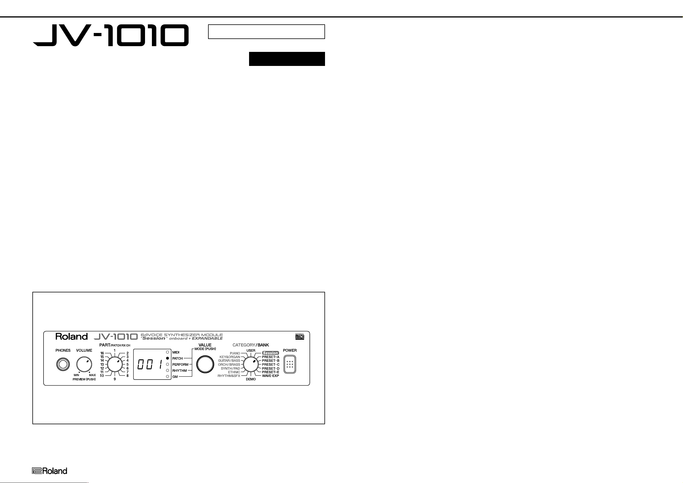
JV-1010 Feb. 1999
SERVICE NOTES
First Edition
Issued by RJA
TABLE OF CONTENTS Page
SPECIFICATIONS ................................................................................ 1
PANEL LAYOUT ........................................................................ 2
EXPLODED VIEW ................................................................................... 3
PARTS LIST .......................................................................... 4
FACTORY RESET ....................................................... 6
Updating the program memory software version ....................... 6
TEST MODE ........................................................................ 7
Error messages ............................................................. 11
Block diagram ............................................................. 12
Circuit diagram ................................................................................... 13
Circuit board ................................................................ 15
目次
主な仕様
パネル配置図
分解図
パーツリスト
ファクトリー・リセット
プログラムメモリーのバージョンアップ方法
テストモード
エラー・メッセージ
ブロック図・配線図
回路図
基板図(フィルム)
SPECIFICATIONS
JV-1010: 64 Voice Synthesizer Module
(Conforms to General MIDI System)
● Number of Parts
16 (Part 10 is Rhythm Part)
● Maximum Polyphony
64 voices
● Preset Memory
Patches: 895 (640 same as the JV-2080 + 255 from "Session")
Performances: 64
Rhythm Sets: 18 (10 same as the JV-2080 + 8 from "Session")
● User Memory
Patches: 128
Performances: 32
Rhythm Sets: 2
● Wave Expansion Boards (sold separately)
Max. 1 Board
* Each Wave Expansion Board includes Patches / Rhythm Sets that make
use of the waves on the board.
● Effects
EFX: 40 sets
Reverb: 1 set (8 types)
Chorus: 1 set
● Display
7 segments, 3 characters (LED)
主な仕様
JV-1010:64ボイス・シンセサイザー・モジュール
(GMシステム対応)
●音源
PCM方式
● パート数
16(パート10はリズム・パート)
● 最大同時発音数
64音
● プリセット・メモリー
パッチ:895(640:JV-2080相当+255:Session)
パフォーマンス:64
リズム・セット:18(10:JV-2080相当+8:Session)
● ユーザー・メモリー
パッチ:128
パフォーマンス:32
リズム・セット:2
● ウェーブ・エクスパンション・ボード(別売)
最大1枚
※各ウェーブ・エクスパンション・ボードには、ボードのウェーブを
使ったパッチ/リズム・セットが記憶されています。
● エフェクト
EFX:40種類
リバーブ:1種類(8タイプ)
コーラス:1種類
● ディスプレイ
7セグメント3桁
● Connectors
Output Jacks (L(Mono), R)
Headphones Jack
MIDI Connectors (IN, OUT, THRU)
Computer Connector (Mac, PC-1, PC-2, MIDI)
● Power Supply
DC 9V (AC Adaptor)
● Current Draw
430 mA
● Dimensions
218 (W) × 237 (D) × 45 (H) mm
8-5/8 (W) × 9-3/8 (D) × 1-13/16 (H) inches
● Weight
1.4 kg / 3 lbs 2 oz (excluding AC Adaptor)
● Accessories
Owner's Manual (Japanese:#71451067)
(English:#71451078)
AC Adaptor (ACI-100C:#00905756)
(ACI-120C:#00905767)
(ACI-230C:#01018312)
(ACB-230E 230VE:#01458278)
(ACB-240A:#12449549)
MIDI CABLE (#23485228)
ORIGINAL CONNECT CORD (#00908323)
CD-ROM (SoundDiver JV/XP, Reference Manual)(#01788623)
Rubber Feet(#00564612)
● 接続端子
アウトプット・ジャック(L(MONO)、R)
ヘッドホン・ジャック
MIDIコネクター(IN、OUT、THRU)
コンピューター端子(Mac、PC-1、PC-2、MIDI)
● 出力インピーダンス
1kΩ
●電源
DC9V(ACアダプター)
● 消費電流
430mA
● 外形寸法
218(幅)×237(奥行)×45(高さ)mm
●重量
1.4kg(ACアダプターを除く)
● 付属品
取扱説明書 (和文:#71451067)
(英文:#71451078)
ACアダプター(ACI-100C)(#00905756)
MIDIケーブル(#23485228)
オーディオ・ケーブル(#00908323)
保証書(#40232334)
ゴム足(#00564612)
Copyright © 1999 by ROLAND CORPORATION
All rights reserved. No part of this publication may be reproduced in any form without the written permission of ROLAND CORPORATION.
© 1999 ローランド 本書の一部、もくしは全部を無断で複写・転載することを禁じます。
17059968 Printed in Japan AA00 (DP)
● Options
Wave Expansion Boards: SR-JV80 series
Rack Mount Adaptor:RAD-50
* In the interest of product improvement, the specifications and/or
appearance of this unit are subject to change without prior notice.
● 別売品
ウェーブ・エクスパンション・ボード:SR-JV80シリーズ
ステレオ・ヘッドホン:RH-20/80/120
MIDIケーブル:MSC-15/25/50
コンピューター・ケーブル:RSC-15N/15AT/15APL
ラック・マウント・アダプター:RAD-50
※
製品の仕様および外観は、改良のため予告なく変更することがあります。
1
Page 2
JV-1010 Feb. 1999
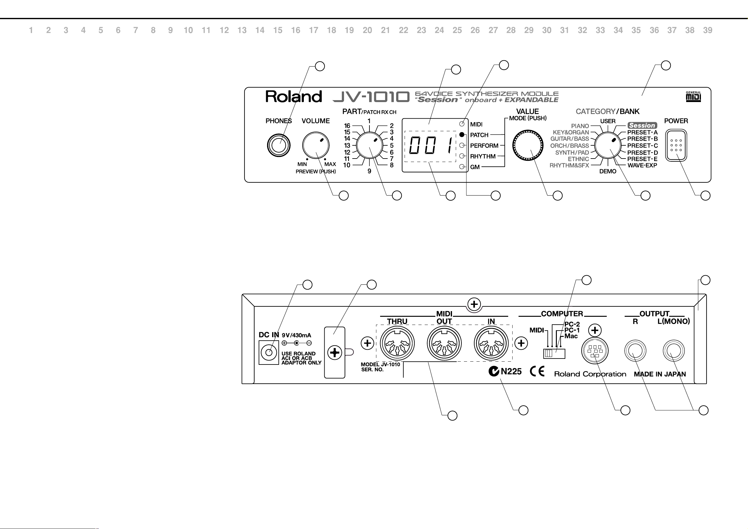
PANEL LAYOUT
A
FRONT VIEW PARTS LIST
NO.
B
C
D
E
F
G
PART CODE
q 22480260 P R-KNOB MF BLK/LCG
01789523 9M/M ROTARY POT. RK0971214
w 22480260 P R-KNOB MF BLK/LCG
01785212 SWITCH (DIGITAL SW) SRRS1G-F0615-1
e 22480260 P R-KNOB MF BLK/LCG
01785212 SWITCH (DIGITAL SW) SRRS1G-F0615-1
r 22485307 M R-KNOB L BLK 248-307
01785790 ROTARY ENCODER RK09710EL-5R4611
t 01785423 DISPLAY COVER
y 00560745 LED (GREEN) SLR-325MCT31
u 00348490 LED (RED) SLR-325VCT31
i 00451423 LED LB-303VA
o 13449172 7SEG 6.5MM JACK HLJ7000-01-3010
!0 32490595 P S-KEY MX BLK
13129369 PUSH SWITCH SPUN19430A
!1 71345534 FRONT PANEL ASSY
H
I
/パネル配置図
/正面図 パーツリスト
PART NAME DESCRIPTION
FRONT VIEW
/正面図
9
1
2
5
8
6
7
11
34
10
J
K
REAR VIEW PARTS LIST
L
M
N
O
NO.
PART CODE
!2 13449720 DC JACK HEC2305-01-250
!3 22365714 CORD HOOK
!4 13429273 MIDI CONNECTOR YKF51-5046 (TRIPRET)
!5 00899223 SLIDE SWITCH SSSF124-S06N1
!6 13429911 DIN JACK TCS7927-28-401
!7 13449283 6.5MM JACK HLJ7101-01-3010
!8 01785401 BOTTOM CHASSIS
!9 71342178 TOP COVER ASSY
P
Q
R
/背面図 パーツリスト
PART NAME DESCRIPTION
REAR VIEW
/背面図
12
13
14
15
19
16 1718
S
T
U
V
2
Page 3
JV-1010 Feb. 1999
A
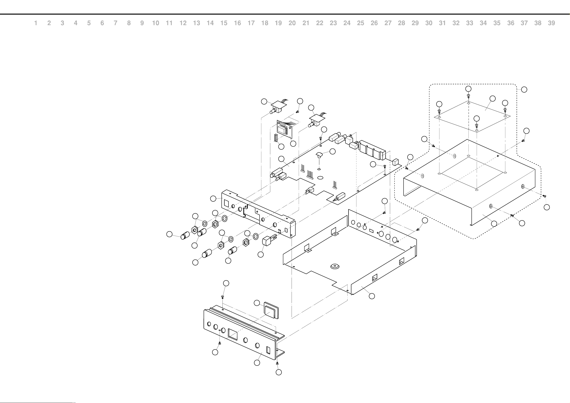
EXPLODED VIEW
/分解図
B
C
D
E
F
G
H
I
J
K
L
M
[
PORTS
[
SCREW
]
NO.
PART CODE
q 22480260 P R-KNOB MF BLK/LCG
w 22485307 M R-KNOB L BLK 248-307
e 32490595 P S-KEY MX BLK
r 01785412 FRONT HOLDER ESD-R-16C
t 71342189 MAIN BOARD ASSY (EXG)
y 71342201 D-SW BOARD ASSY
u 71342190 LED BOARD ASSY
i 01785467 ISOLATOR LED MASK
o 01789534 PWB SPACER RSPS-6L
!0 71345534 FRONT PANEL ASSY
!1 01785423 DISPLAY COVER
!2 01785401 BOTTOM CHASSIS
!3 71342178 TOP COVER ASSY
!4 01785445 TOP COVER
!5 22025583 EXP COVER 202-583
]
NO.
PART CODE
a 40011090 SCREW M3×6 BINDING TAPTITE B BZC
b 40011145 SCREW M3×6 FLAT TAPTITE B FE BZC
c 40011056 SCREW M3×6 BINDING TAPTITE B ZC
d 40011490 SCREW M3×6 PAN MACHINE W/SW BZC
e 40011312 SCREW M3×6 BINDING P-TITE FE BZC
f This NUT and WASER are included in the #01789523 9M/M ROTARY POT.
このナットとワッシャーは、017895239M/MROTARYPOTに含まれます。
g This NUT and WASER are included in the #01785212 SWITCH (DIGITAL SW)
このナットとワッシャーは、01785212SWITCH(DIGTALSW)に含まれます。
h This NUT and WASER are included in the #01785790 ROTARY ENCODER.
このナットとワッシャーは、01785790ROTARYENCODERに含まれます。
PART NAME DESCRIPTION
PART NAME DESCRIPTION
1
a
6
8
5
4
f
g
h
g
a
6
c
a
7
9
a
c
d
a
a
e
15
a
14
13
a
a
a
N
O
P
Q
R
S
T
U
V
1
3
2
1
b
12
11
a
10
a
3
Page 4

JV-1010 Feb. 1999
/ハイブリット
PARTS LIST
SAFETY PRECAUTION:*1
The parts marked
related characteristics.
Use only listed parts for
replacement.
安全上の注意:*1
が付いている部品は、安全
上特別な規格でつくられたも
のです。
交換の際は、指定された部品
番号以外の部品は使わないよ
うにして下さい。
Note 1 : Consider about the natural environment carefully before through the old lithium battery away when you exchange to the new one.you exchange to the new one.
注意1 : リチウム電池の交換時に、不要になったリチウム電池は、環境問題を十分考慮した上で処理して下さい。
have safety-
/パーツリスト
The parts marked #
are new (initial
parts). *2
#の付いた部品は新
規部品です。*2
CONSIDERATIONS ON PARTS ORDERING
When ordering any parts listed in the parts list, please specify the following items in the order sheet.
Failure to completely fill the above items with correct number and description will result in delayed or even
undelivered replacement.
パーツ発注に関するお願い
オーダーシートには、必ず下記の4項目は正確に記入して下さい。(例外は除く)
もし記入洩れ、誤記等が有る場合、必要部品が発送できなかったり、大幅な遅れの原因になりま
す。御協力をお願いします。
QTY PART NUMBER DESCRIPTION MODEL NUMBER
10 22575241 Sharp key C-20/50
Ex.
15 2247017300 Knob (orange) DAC-15D
必要数 パーツナンバー 品名 使用機種
10 22575241 Sharp key C-20/50
例)
15 2247017300 Knob (orange) DAC-15D
*1 *2
↓↓
CASING Q'ty
/ケース
# 01785423 DISPLAY COVER 1
# 71342178 TOP COVER ASSY 1
NOTE: 'TOP COVER ASSY' includes the follwing parts.
注意:補修用MAINBOARDASSYは、下記の部品を含みます。
# 01785445 TOP COVER
22025583 EXP COVER202-583
# 71345534 FRONT PANEL ASSY 1
CHASSIS
/シャーシ
# 01785401 BOTTOM CHASSIS 1
# 01785412 FRONT HOLDER FRONT 1
KNOB, BUTTON
/つまみ、ボタン
32490595 P S-KEY MX BLK 1
22480260 P R-KNOB MF BLK/LCG 3
22485307 M R-KNOB L BLK 248-307 1
SWITCH
/スイッチ
13129369 SPUN19430A PUSH SWITCH SW2 on MAIN 1
00899223 SSSF124-S06N1 SLIDE SWITCH SW1 on MAIN 1
# 01785212 SRRS1G-F0615-1 (DIGITAL SW) SWITCH SW3 on D-SW 1
JACK, SOCKET
/ジャック、ソケット
13429273 YKF51-5046 (TRIPRET) MIDI CONNECTOR JK4 on MAIN 1
13429911 TCS7927-28-401 (RS422) DIN JACK JK5 on MAIN 1
13449172 HLJ7000-01-3010 6.5MM JACK JK6 on MAIN 1
13449283 HLJ7101-01-3010 6.5MM JACK JK2,3 on MAIN 2
13449720 HEC2305-01-250 DC JACK JK1 on MAIN 1
DISPLAY UNIT
/表示ユニット
00451423 LB-303VA 7SEG LED LED1 on LED 1
PCB ASSY
/基板完成品
# E 71342189 MAIN BOARD ASSY (EXG) 1
NOTE: 'MAIN BOARD ASSY' includes the following parts.
注意:補修用MAINBOARDASSYは、下記の部品を含みます。
12189810 PCB SPACER WLS-14-094VO 3
# 71342190 LED BOARD ASSY 1
NOTE: 'LED BOARD ASSY' includes the following parts.
注意:補修用REDBOARDASSYは、下記の部品を含みます。
# 01893545 W2 WIRING 14X85-P2.0 1
# 71342201 D-SW BOARD ASSY 2
NOTE: 'D-SW BOARD ASSY' includes the following parts.
注意:補修用D-SWBOARDASSYは、下記の部品を含みます。
# 01893523 W1 RIBBON CABLE 5X50-P2.0 UL-2678 1
MB → Main Board Assy
VB → VR Board Assy
EB → ENC Board Assy
JB → Jack Board Assy
IC
# 01897978 HD6437016F28 MIKT1 IC (CPU) IC1 on MAIN 1
01679978 RA09-002 (XP6) IC (CUSTOM) IC3 on MAIN 1
01122412 TC551001CF-70L IC (SRAM) IC2 on MAIN 1
01679556 MN414260DSJ-06T1 IC (DRAM) IC4,5 on MAIN 2
01783445
01783456
01561945 LH28F160S5T-L70 IC (FLASH MEMORY) IC14 on MAIN
01451578 AK4324-VF-E2 IC (DAC) IC26 on MAIN 1
15269219H0 HD74LS05FPEL IC (TTL) IC31 on MAIN 1
15259782T0 TC74HC257AF(EL) IC IC10 on MAIN 1
15259884 TC7S08F(TE85L) IC (CMOS) IC100 on MAIN 1
15259887 TC7SU04F(TE85L) IC (CMOS) IC32 on MAIN 1
15259740T0 TC74HC139AF(EL) IC (HS-CMOS) IC15 on MAIN 1
15249111 TC7WU04F(TE12L) IC (C MOS) IC12 on MAIN 1
15249112 TC7W32F(TE12L) IC (C MOS) IC9 on MAIN 1
00232645 TC7W14F(TE12L) IC (CMOS) IC27 on MAIN 1
15289111 TL062CPS ELL2000 IC (OP AMP) JFET IC34 on MAIN 1
15189261 M5218AFP-600E IC (OP AMP) BIPOLAR IC20,22 on MAIN 2
15289105 UPC4570G2-E2 IC (OP AMP) BIPOLAR IC25,28 on MAIN 2
01670890 PQ3DZ53U IC (REGULATOR) IC33 on MAIN 1
00344390 TA7805F(TE16L) IC (REGULATOR) IC23 on MAIN 1
00122978 SI-8221L SWITCHING REGULATOR IC18 on MAIN 1
15289404 IR3M03N2-T2 IC (REGULATOR) DC-DC IC24 on MAIN 1
01783534 SN7534051NS IC IC29 on MAIN 1
15199937 M51953BFP-600C IC (RESET IC) IC19 on MAIN 1
15289125 PC-410KT 178FAY IC (PHOTO COUPLER) IC30 on MAIN 1
# 01899267 LH537UYB IC (MASKROM) IC35 on MAIN
TRANSISTOR
01121278 2SA1576A T106 QRS TRANSISTOR Q1 on MAIN 1
01121289 2SC4081 T106 QRS TRANSISTOR Q2,4,21 on MAIN 3
15319105 2SC3326-A(TE85L) TRANSISTOR on MAIN 4
01783612 RN2426(TE85L) TRANSISTOR on MAIN 5
15329516 DTC114EKT146 TRANSISTOR on MAIN 9
DIODE
15339142 RB705D T146 SCHOTTKY DIODE DA2 on MAIN 1
01017512 RB411D T146 SCHOTTKY DIODE D11 on MAIN 1
15039142 S5688G(TPB5) 1A/400V RECTIFIER DIODE D2 on MAIN 1
01121323 DA204U T106 ARRAY DIODE DA1 on MAIN 1
01126823 RD20S-T1 B ZENER DIODE on MAIN 6
01565678 RD5.1M-T2B ZENER DIODE on MAIN 2
00348490 SLR-325VCT31 LED (RED) LED3,4,5,6 on LED 4
00560745 SLR-325MCT31 LED (GREEN) LED2 on LED 1
RESISTOR
01455989 ERDS1VJ101T 1/2W CARBON RESISTOR R42,54 on MAIN 2
15399409 RPC10T 332 J 1/10W MTL.FILM RESISTOR on MAIN 10
15399417 RPC10T 682 J 1/10W MTL.FILM RESISTOR on MAIN 13
15399441 RPC10T 683 J MTL.FILM RESISTOR on MAIN 8
01011856 RPC05T 0R0 J MTL.FILM RESISTER on MAIN 13
15399401 RPC10T 152 J MTL.FILM RESISTOR on MAIN 4
00566956 RPC05T 390 J MTL.FILM RESISTOR on MAIN 1
00567034 RPC05T 121 J MTL.FILM RESISTOR on MAIN 1
00567067 RPC05T 221 J MTL.FILM RESISTOR on MAIN 5
00567078 RPC05T 271 J MTL.FILM RESISTOR on MAIN 1
00567112 RPC05T 471 J MTL.FILM RESISTOR on MAIN 1
00567134 RPC05T 681 J MTL.FILM RESISTOR on MAIN 1
15399393 RPC10T 681 J 1/10W MTL.FILM RESISTOR on MAIN 2
15399373 RPC10T 101 J 1/10W MTL.FILM RESISTOR on MAIN 4
15399349 RPC10T 100 J MTL.FILM RESISTOR on MAIN 6
15399369 RPC10T 680 J 1/10W MTL.FILM RESISTOR on MAIN 2
15399415 RPC10T 562 J 1/10W MTL.FILM RESISTOR on MAIN 4
15399425 RPC10T 153 J MTL.FILM RESISTOR on MAIN 1
15399433 RPC10T 333 J 1/10W MTL.FILM RESISTOR on MAIN 2
00567156 RPC05T 102 J MTL.FILM RESISTOR on MAIN 2
LHMN0PVW(MIKT1 WAVE ROM A)
LHMN0PU5(MIKT1 WAVE ROM B)
/トランジスター
/ダイオード
/抵抗
IC (MASK ROM) IC6 on MAIN 1
IC (MASK ROM) IC7 on MAIN 1
(Serial No. ZM 10100~ZM23799)1
(Serial No.ZM23800~)
1
4
Page 5
JV-1010 Feb. 1999
00567212 RPC05T 332 J MTL.FILM RESISTOR on MAIN 2
00567245 RPC05T 472 J MTL.FILM RESISTOR on MAIN 3
00567301 RPC05T 153 J MTL.FILM RESISTOR on MAIN 1
00567378 RPC05T 473 J MTL.FILM RESISTOR on MAIN 1
00567556 RPC05T 105 J MTL.FILM RESISTOR on MAIN 1
01011256 SR73K2ETD 0.47JOHM 1/2W MTL.FILM RESISTOR on MAIN 1
15399429 RPC10T 223 J 1/10W MTL.FILM RESISTOR on MAIN 1
15399405 RPC10T 222 J 1/10W MTL.FILM RESISTOR on MAIN 1
15399301 RPC10T 0R0 J MTL.FILM RESISTOR on MAIN 6
15399421 RPC10T 103 J 1/10W MTL.FILM RESISTOR on MAIN 1
15399377 RPC10T 151 J MTL.FILM RESISTOR on MAIN 9
15399397 RPC10T 102 J 1/10W MTL.FILM RESISTOR on MAIN 2
00567023 RPC05T 101 J MTL.FILM RESISTOR on MAIN 8
00567289 RPC05T 103 J MTL.FILM RESISTOR on MAIN 17
00567412 RPC05T 104 J MTL.FILM RESISTOR on MAIN 1
15399385 RPC10T 331 J MTL.FILM RESISTOR on MAIN 2
15399381 RPC10T 221 J 1/10W MTL.FILM RESISTOR on MAIN 1
00566867 RPC05T 100 J MTL.FILM RESISTOR on MAIN 2
15409113 EXBV8V103JV RESISTOR ARRAY on MAIN 9
01013923 EXBV8V100JV RESISTOR ARRAY on MAIN 6
01457145 EXBE10C103J RESISTER ARRAY on MAIN 3
00126112 EXBV8V101JV RESISTOR ARRAY on MAIN 7
POTENTIOMETER
# 01789523 RK0971214 9M/M ROTARY POT. VR1 on MAIN 1
CAPACITOR
# 15359433R0 GRM40B561K50PT10 CERAMIC CAPACITOR on MAIN 2
# 15359437R0 GRM40B122K50PT10 CERAMIC CAPACITOR on MAIN 2
15359206R0 GRM40F104Z25PT10 CERAMIC CAPACITOR on MAIN 2
# 01672412 GRM39CH150J50PT CERAMIC CAPACITOR on MAIN 2
01672423 GRM40CH101J50PT CERAMIC CAPACITOR on MAIN 4
# 01675190 GRM39CH220J50PT CERAMIC CAPACITOR on MAIN 2
# 01675256 GRM39CH680J50PT CERAMIC CAPACITOR on MAIN 2
01675367 GRM39CH471J50PT CERAMIC CAPACITOR on MAIN 1
01675278 GRM39CH101J50PT CERAMIC CAPACITOR on MAIN 18
00567823 GRM39B102K50PT CERAMIC CAPACITOR on MAIN 3
00567978 GRM39F104Z25PT CERAMIC CAPACITOR on MAIN 65
01349312 GRM39F105Z10PT CERAMIC CAPACITOR on MAIN 1
# 00567834 GRM39B122K50PT CERAMIC CAPACITOR on MAIN 3
00567945 GRM39B103K50PT CERAMIC CAPACITOR on MAIN 3
# 13519627M0 ECKR1H271KB5 CERAMIC CAPACITOR on MAIN 1
# 01675167 GRM39CH100D50PT CERAMIC CAPACITOR on MAIN 1
13549255M0 ECQ-B1H102JF3 POLYEST.CAPACITOR on MAIN 2
13549341 ECQ-B1H101KF3 POLYEST. CAPACITOR on MAIN 2
# 13639566J0 SME25VB10TP CHEMICAL CAPACITOR on MAIN 4
13639574 SME25VB4R7TP CHEMICAL CAPACITOR on MAIN 7
13639602J0 SME50VB1TP CHEMICAL CAPACITOR on MAIN 1
13639513J0 SME6.3VB220TP 220UF/6.3V CHEMICAL CAPACITOR on MAIN 2
13649646 SME16VB470TP 470UF/16V CHEMICAL CAPACITOR on MAIN 1
13639514M0 ECA0JM331B CHEMICAL CAPASITOR on MAIN 2
13629624S0 6SC10M+T (OS) 6.3V10 CHEMICAL CAPACITOR on MAIN 1
13639550J0 SME16VB100TP 100UF/16V CHEMICAL CAPACITOR on MAIN 1
13639569J0 SME25VB47TP CHEMICAL CAPACITOR on MAIN 16
/ボリューム
/コンデンサー
ENCODER
# 01785790 RK09710EL-5R4611 ROTARY ENCODER EN1 on MAIN 1
CONNECTOR
13369600 52147-0510(5P) CONNECTOR CN3,5 on MAIN 2
13369936 53253-1410 (2MM PITCH) CONNECTOR CN7 on MAIN 1
13429833 52411-0402 40P CONNECTOR CN1 on MAIN 1
13429294 51048-0500(5P) CABLE HOLDER CN2 on D-SW 1
SCREW
40011090 SCREW M3X6 BINDING TAPTITE B BZC 8
40011056 SCREW M3X6 BINDING TAPTITE B ZC 6
40011145 SCREW M3X6 FLAT TAPTITE B FE BZC 2
40011312 SCREW M3X8 BINDING P-TITE FE BZC 2
40011490 SCREW M3X6 PAN MACHINE W/SW BZC 1
PACKING
00892734 ADAPTOR PAD 1
# 01891090 PAD 1
00906423 MODULE PAD L SS-55ST 1
00906445 MODULE PAD R SC-55ST 1
# 01785434 PACKING CASE 1
# 01897990 OUTER PACKING CASE OUTER 1
MISCELIANEOUS
12569249 LITHIUM BATTERY CR2032 220MAH/3V 1
22365714 CORD HOOK 236-714 1
01785467 ISOLATOR LED MASK 1
# 01789534 PWB SPACER RSPS-6L 1
12189815 BATTERY HOLDER BH-32 BT1 on MAIN 1
ACCESSORIES (STANDARD)
00905756 AC ADAPTOR ACI-100C 1
00905767 AC ADAPTOR ACI-120C 1
01018312 AC ADAPTOR ACI-230C 1
01458278 AC ADAPTOR ACB-230E 230VE(DC9V.1200MA) 1
12449549 AC ADAPTOR ACB-240A 1
00564612 FOOT C4305+N#500 4
01788623 CD-ROM (EXP ONLY) SOUND EDITOR+JV-1010 MANUAL 1
23485228 MIDI CABLE 348-228 1M (BLACK) 1
00908323 ORIGINAL CONNECT CORD RCA PIN 1.0M 4ADPT 1
# 71451067 OWNER'S MANUAL JAPANESE 1
# 71451078 OWNER'S MANUAL ENGLISH 1
40232334 (Japan Only) 1
/エンコーダー
/コネクター
/ねじ類
/梱包材
/その他
/標準付属品
(海外用)
Contents of CD-ROM
• SoundDriver JV/XP
• MIDI Driver
• JV/1010 Reference Manual
• Licence Agreement
保証書セット
INDUCTOR, COIL, FILTER
01346089 SBC3-331-551 CHOKE COIL on MAIN 2
00237212 SH-202 CHOKE COIL on MAIN 1
12449347 EXC ELDR35V FERRITE-BEAD on MAIN 6
01340834 EXCML20A390 FERRITE-BEAD on MAIN 1
01455623 N2012Z102T01 FERRITE-BEAD on MAIN 12
CRYSTAL, RESONATOR
00901912 MA-406 24.576MHZ TE24 CRYSTAL X1 on MAIN 1
01126267 MA-406 7.056MHZ CRYSTAL X2 on MAIN 1
/インダクター、コイル、フィルター
/クリスタル、発振子
5
Page 6

JV-1010 Feb. 1999
FACTORY RESET
(1) Turn on the power.
(2) ((2)Press [VALUE] to select except PATCH
MODE(PERFORM,RHYTHM,GM).
(3) Hold on to press [VOLUME],press the [VALUE].
(4) Rotate [CATEGORY/BANK] to select PIANO(Factory
Reset).
Display show as follows
(5) Press [VALUE].
The Factory Reset page will appear.
(6) Press[VALUE]
Factory Reset operation will be carried out.
ファクトリー・リセット
(1) 電源を投入します。
(2)
VALUEつまみを押して、パッチ・モード(PATCH)以
外のモード(PERFORM,RHYTHM,GM)に切り替えます。
(3)
VOLUMEつまみを押しながらVALUEつまみを押します。
(4) CATEGORY/BANKつまみを回してPIANO(Factory
Reset)を選びます
ディスプレイには次のように表示されます。
(5) VALUEつまみを押します。
ファクトリー・リセットの画面に入ります
(6) VALUEつまみを押します。
ファクトリー・リセットが実行されます。
Updating the program memory
software version
JV-1010 user the FLASH MEMORY.
These ROMs can be update the program by transferring the data in
upgrading disk (SMF format),through MIDI.
Required Items
• JV-1010 Version Up Disk Set ( Pno. 17048955 )
(The Version up disk contains the JV-1010 program converted
into SMF data.Obtain the latest version from the service center.)
• Sequencer(Anything that will play back SMF will do.)
• MIDI cable
Update procedure
1. Connect MIDI OUT of the Sequencer with MIDI IN of the JV-
1010.
2. Rotate [PART] to select 14,rotate [CATEGORY] to select
GUITAR/BASS.
Turn the power on while holding down [VOLUME][VALUE].
(Wait three seconds)
プログラムメモリーのバージョン
アップ方法
JV-1010は初期バージョン(SerialNo.ZM10100〜ZM23799)に
おいてプログラムROMにフラッシュメモリーが使用されてい
ます。
このプログラムROMは外部シーケンサーよりMIDIによるプログ
ラムのアップデートが可能です。手順は下記のとおりです。
用意するもの
・ JV-1010Ver.upDisk(部品番号:17048955)
(Ver.upDiskにはJV-1010のプログラムをSMFにコンバー
トしたものが入っています。
サービスセンターから最新のものを取り寄せてください。
・ SMFプレイヤー(シーケンサー)
(SMFデータが再生できれば、何でもよい。XP-80等)
・ MIDIケーブル
バージョンアップ作業
1. MIDIケーブルを外部シーケンサーのMIDIOUTからJV1010のMIDIINにつなぎます。
2. JV-1010の[PART:14][CATEGORY:GUITAR/BASS]に合わ
せ、[VOLUME][VALUE]を押しながら電源を入れます。
(3秒間押し続けます)
3. Release [VOLUME][VALUE] button. Hold down
[VOLUME] button.
3. 一度押していた指をはなし、その後もう一度[VOL UM E ]
のみを押します。
6
Page 7

JV-1010 Feb. 1999
Memory&Battery
d
When you enter Update mode, display shows following.
4. Check to see that display shows as described above and then
playback the SMF data.
When the update procedure is in normal operation, MIDI LED
will blink.
The file names are as follows.
000001.mid
000002.mid
|
00000#.mid
5. After the all files has been played, Turn the power off.
Update procedure is complete.
After executing update procedure, be perform the Factory
Reset.
押し続けると、DISPLAYに以下のように表示されます。
4. 上の表示を確認してから、外部シーケンサーをプレイし
ます。
正常にバージョンアップされているとMIDIのLEDが点滅
します。
ファイルの名前は、下記のとおりです。
000001.mid
000002.mid
¦
00000#.mid
5. 全てのファイルをプレイし終わったら、電源をOFFし
ます。
以上でアップデートは完了です。
アップデートが終了したら必ずファクトリーリセット
を行って下さい。
TEST MODE
NOTE:
When you execute test mode, the various parameters will be given
special settings.
❍Required items
• MIDI Cable ×1
• Monitor Speaker(MA-12 etc.) ×2
• Computer Test Cable(17049906) ×1
• Expansion Board ×1
❍Entering the TEST MODE
Connect the Monitor Speaker to the OUTPUT of the JV-1010.
Set the Rear select SW to Mac.
Rotate [PART] to select 15, rotate [CATEGORY] to select
KEY&ORGAN.
Turn the power on while holding down [VOLUME](Wait three
seconds).
Release [Volume]button. Hold down [VOLUME]button.
テストモード
注意:
テストモードを実行すると各種設定が特殊な設定になりま
す。テストモードを実行した後、ファクトリーリセットを
行ってください。
❍用意するもの
・ MIDIケーブル ×1
・ モニタースピーカー(MA-12等) ×2
・
コンピューターテストケーブル
・ エクスパンションボード ×1
❍テストモードの入りかた
JV-1010のアウトプット端子にモニタースピーカーを接続します。
リアのSELECTSWを[Mac]に合わせます。
[PART:15]、[CATEGORY:KEY&ORGAN]に合わせ、
[VOLUME]を押しながら電源ONします。(3秒間押し続け
ます)
一度押していた指をはなし、その後もう一度[VOLUME]を押
します。
押し続けるとDISPLAYに以下のように表示されます。
(17049906) ×1
When you enter TEST MODE, 7seg LED Test runs automatically.
❍To exit the Test Mode
Turn the power off.
❍Test Item
The JV-1010 has the following 8 items.
Rotate [CATEGORY] to select test item.
VersionNo.
7-segLED
テストモードに入るとすぐに7-segLEDテストに入ります。
❍
テストモードの抜けかた
もう一度電源を入れ直すことにより、通常のモードに戻ります。
❍テスト項目
JV-1010には以下のテスト項目があります。
テストモードの各項目はカテゴリーSWを回して選択します。
ExpansionBoar
MIDI
ComputerI/F
SoundCheck
Encoder
Digital-SW
7
Page 8

JV-1010 Feb. 1999
0: 7segLED Test
1: Identifying the Program Version
2: Memory and Battery Test
3: Expansion Board Test
4: MIDI Test
5: Computer I/F Test
6: Sound check
7: Encoder Test
8: Digital SW Test
0: 7segLED Test
7segLED displays "8." in order of left,center and right.
Troubleshooting for 7-seg LED Test
Result of Test Check
Not lit LED1, Q5 to 16
/テストの結果 /チェック項目
/不灯
0: 7-segLEDテスト
1: バージョン表示
2: MEMORY&バッテリー
3: Expansion・ボードテスト
4: MIDIテスト
5: コンピューター・インターフェース・テスト
6: サウンドチェック
7: エンコーダー・テスト
8: デジタルSWテスト
0: 7segLEDテスト
DISPLAYに8.の文字が左から右へ移動します。
7-segLEDテストトラブルシューティング
Troubleshooting for Memory and Battery Test
Result of Test Check
/テストの結果 /チェック項目
MEMORY&バッテリーテスト・トラブルシューティング
IC1
IC14 or 35
IC4
IC2
IC3 or 5
1: Identifying the Program Version
The 7-seg LED shows the version number.
2: Memory and Battery Test
When you press [VALUE], Memory and Battery Test runs
automatically.
You can check the following display appears.
1:バージョン表示
CPUとROMのバージョンを確認します。
2:MEMORY&バッテリーテスト
[VALUE]を押すと自動的にテストを行います
以下の順に表示されることを確認して下さい。
OK
3: Expansion Board Test
When you press [VALUE], Expansion Board Test runs
automatically.
You can check the following display appears.
Troubleshooting for Expansion Board Test
Result of Test Check
/テストの結果 /チェック項目
Battery (CR2032) BT1, IC34
3.Expansion・ボードテスト
[VALUE]を押すと自動的にテストを行います
以下の順に表示されることを確認して下さい。
OK
Expansion・ボード・テスト・トラブルシューティング
CN1
IC7
IC6
8
Page 9

JV-1010 Feb. 1999
4: MIDI Test
The following display will appear.
Make a loop with MIDI cable that connects MIDI IN and MIDI
OUT.
When MIDI cable is connected, MIDI indicator lights.
Troubleshooting for MIDI Test
Result of Test Check
MIDI indicator does not lit. IC30, IC31, IC1
5:Computer I/F Test
To perform the Serial Test in Test mode, the "COMPUTER Test
cable"(17049906)is needed.
Please place an order for this cable with your Local Roland Service
when neccessary.
When you Switch the Rear select SW in any order, Correspondence
LED will light.
Switches LED
Mac GM
PC-1 RHYTHM
PC-2 PERFORM
MIDI PATCH
/テストの結果 /チェック項目
/MIDIインジケーターが点灯しない
4:MIDIテスト
以下の表示になります。
MIDI・OUT端子とMIDI・IN端子をMIDIケーブルでループさ
せます。MIDIケーブルを接続している時、MIDIインジケー
ターが点灯する事を確認します。
MIDIテスト・トラブルシューティング
5:コンピューター・インターフェース・テスト
このテストを行うには、コンピューターテストケーブルが必
要です。
必要な場合には、ローランドサービスセンターまで注文して
ください。
(PartNo.17049906)
リア面のSWを切り替えるとフロント面の対応するLEDが
点灯します。
Switches LED
Mac GM
PC-1 RHYTHM
PC-2 PERFORM
MIDI PATCH
コンピューター・インターフェース・テスト・トラブル
シューティング
Result of Test Check
(PC-1, PC-2)
No response SW1, Q3
6: Sound Check
When sound test starts, at first sound output from L ch of
OUTPUT and Headphone.
Every time press the [VALUE], output channel is switched.
start OUTPUT/L sine wave
[VALUE] OUTPUT/R rectangular wave
[VALUE] OUTPUT/L&R sine wave
/テストの結果 /チェック項目
IC29, IC32
/リア面のSWでLEDが反応しない
6:サウンドチェック
このテストに入ると、最初はOUTPUTとヘッドフォンの
左から音が出ます。
[VALUE]を押す度に出力が切り替わります。
/サイン波
/矩形波
/サイン波
Set the selector switch on the rear panel to "mac"
Check the waveform(1MHz) is observed with the oscilloscope.
Set the selector switch on the rear panel to "PC-1"or"PC-2"
Check the 7-seg LED still display, even though trun on a switch of
the COMPUTER test cable.
切り替えSWがMacのとき、
テストプラグのプローブをオシロスコープで観測し、1MHz
の信号が出ていることを確認します。
切り替えSWがPC-1またはPC-2のとき、
DISPLAYの表示が以下のようになるかどうか確認してくださ
い。
また、テストケーブルのPUSHSWを切り替えても表示が変わ
らないことを確認して下さい。
7:Encoder Test
Check that the display of 7-seg LED changes by rotating the
encoder clockwise and counter clockwise.
Troubleshooting for Encoder Test
Result of Test Check
No response EN1, IC27
/テストの結果 /チェック項目
/エンコーダーを回しても表示が変化しない
7:エンコーダー・テスト
エンコーダーを左右に回し、DISPLAYの表示が変化すること
を確認して下さい。
エンコーダー・テスト・トラブルシューティング
9
Page 10

JV-1010 Feb. 1999
8: DIGITAL-SW Test
Check that the following display appears by rotating the [PART]
clockwise.
15
16
1
8:デジタルSWテスト
パートを時計回りに回して、表示が以下のようになるかを確
認してください。
Check that the following display appears by rotating the
[CATEGORY] clockwise.
DEMO to GUITAR/BASS Invalid
KEY&ORGAN
PIANO
USER
パートを1に合わせると「カテゴリー」のSWのテストに入り
ます。
カテゴリーを時計回りに回して、以下の表示になることを確
認してください。
DEMO〜GUITAR/BASS 無効
2
16
1
(Sound of Bell output)
(ベルの音が鳴ります)
Session
PRESET-A
PIANO
USER
(Sound of Bell output)
(ベルの音が鳴ります)
10
Troubleshooting for DIGITAL-SW Test
Result of Test Check
No response SW3, IC10
/テストの結果 /チェック項目
/
SWを回しても変化しない
デジタルSW・テスト・トラブルシューティング
Page 11

JV-1010 Feb. 1999
■ Error messages
● (Battery Low)
Situation : The internal backup battery has run down.
Action : Contact a nearby qualified Roland service personnel.
● (MIDI Buffer Full)
Situation : More MIDI data was received in a short time than could
be processed.
Action : Reduce the amount of MIDI data that is being
transmitted.
■エラー・メッセージ
原因: 本体バックアップ用電池が消耗しています。
対応: 最寄りのローランド・サービスにご連絡下さい。
原因: 受信したMIDIメッセージの量が多いため、正し く
処理できませんでした。
対応: 送信するMIDIメッセージの量を減らして下さい。
● (Receive Data Error)
Situation : A MIDI message could not be received correctly.
Action : If this message appears repeatedly, there is a problem
with the content of the MIDI messages.
● (User Memory Damaged)
Situation : The data in the USER group has been damaged.
Action : Perform the Factory Reset operation.
● (No Patch)
原因: MIDIメッセージが正しく受信できませんでした。
対応: 何度も同じメッセージが表示されるときは、MIDI
メッセージの内容に問題があります。
原因: USERのデータが壊れています。
対応: ファクトリー・リセットの操作で、出荷時の設定に戻
して下さい。
● (MIDI Check Sum Error)
Situation : Exclusive data was not received correctly.It is possible
that Check Sum value was incorrect.
Action : Check the value of the Check Sum. If it is incorrect,
correct the value and re-do the operation.
● (MIDI Communication Error)
Situation : It is possible that a MIDI cable has been pulled out or
broken.
Action : Check the MIDI cables.
原因: 受信したシステム・エクスクルーシブ・メッセージの
チェック・サムの値が間違っています。
対応: チェック・サムの値を修正して下さい。
原因: MIDIケーブルが抜けているか、断線している可能性
があります。
対応: 接続を確認したり、MIDIケーブルを交換してみてく
ださい。
Situation : You have selected EXP-B without using the Expansion
Board.(Using MIDI)
Action : Connect the Expansion Board to increase the maximum
number of sounds.
● (- - -)
Situation : You have selected EXP-B without using the Expansion
Board.
Action : Connect the Expansion Board to increase the maximum
number of sounds.
原因: エクスパンション・ボードを追加していないのに、
MIDIでEXP-Bを選択しました。
対応: 音色数を増やしたい時はエクスパンション・ボードを
追加してください。
原因: エクスパンション・ボードを追加していないのに、パ
ネルからEXP-Bを選択しました。
対応: 音色数を増やしたい時はエクスパンション・ボードを
追加してください。
11
Page 12

JV-1010 Feb. 1999
BLOCK DIAGRAM/ブロック図・配線図
A
B
CN20
C
PC Interface
D
E
F
G
H
I
J
K
L
M
N
O
P
Q
R
Comp I/F
JK5
Comp select SW
SW1
THRU
OUT
MIDI
IN
D-SW
BOARD
D-SW
BOARD
Part
SW
Category
IC10
Multiplexer
SW
Encoder
EN1
IC1
CPU
LED
LED BOARD
SRAM DRAM
IC2
ADRESS & DATA
FLASH
MEMORY
IC14
JK1
DC JACK
Power SW
MASK
SW2
IC4
ROM
IC35
SW Reg
IC18
DAC
IC26
D+5V
A+5V
IC3
XP6
Differential
Amplifier
IC25
WAVE
AB
IC6
DRAM
Effect
IC5
Filter
IC28
WAVE
IC7
Buffer
Volume
VR1
IC22
EXP-B
CN1
JK2
OUTPUT L/MONO
JK3
OUTPUT R
JK6
PHONES
Amplifier
IC20
S
T
U
V
12
IC23
Regulator
DC-DC Converter
A-5V
Page 13

JV-1010 Feb. 1999
FWP
XCPURST
XRS
D
D
5
D
5
D
D
D
CN20
IL-S-8P-S2T2-EF
2
2
3
8
IC101A
HD74LS05FP
1
HD74LS05FP
10
HD74LS05FP
0.1
R316
0
R315
C313
100P
TXD1
COMPOUT
CPUOUT
COMPIN
SSSS222-01-A
11
13
SSSS222-01-A
R356
CIRCUIT DIAGRAM 1/1
A
/回路図
B
C
D
E
F
G
H
I
J
K
L
M
N
O
P
Q
R
HD64F7017
Serial No.
ZM10100~ZM10199:
HD6437016EAF
Serial No.
ZM10200~:
Change information
Serial No.
/対象シリアル番号:
Z10100~ZM10199
S
T
U
V
There are follwing parts on the Main Board Assy
以下のパーツが実装されています。
IC101, SW10, CN20
R314
1K
5 6
9 8
11
13
D
+
5
IC101G
+
14
C312
12
7
+
10K
IC101B
3 4
2
There are not following parts on the Main Board Assy
以下のパーツが実装されていません。
R355
R356
+
5
8
7
CPUOUT
7
6
CPUIN
6
5
5
4
MD1
4
3
1
XCPURST
1
D
T
CPUIN
R355
NIU
21
22
23
RXD1
SW10B
NIU
SW10A
12
13
Page 14

JV-1010 Feb. 1999
CIRCUIT DIAGRAM 2/2
A
/回路図
B
C
D
E
F
G
H
I
J
K
L
M
N
O
+
5D
P
Q
PD-CNTL
PD-CNTL
XRST
R308
R307
47K
D
1
2
C305
0
0.01
D
C306
0.1
53
IC100
TC7S08F
SD
WCK
D
BCK
4
256FS
D
R
S
T
DC IN
9V/430mA
ACI/ACB
C67
0.1
SD
WCK
BCK
256FS
+
Q21
5.1MB
R26
D10
3.3K
5.1MB
R31
3.3K
1
R125
3.3K
A
2SC4081
2
3
1
L100
EXCELDR35V
A
JK2
HLJ7101-01-3010
2
4
1
JK3
HLJ7101-01-3010
2
4
1
L101
EXCELDR35V
C80
A
0.1
C140
0.1
A
A9
R129
1K
D12
13
AA
23
Q4
JK6
HLJ7000-01-3010
D
D
D
2SC4081
1
2SC4081
23
1
C153
0.1
R27
R29
15K
220
R30
3.3K
C35
23
220/6.3
Q2
AAA
1
A5
C36
0.1
32
R32
22K
-A5-
Q1
2SA1576A
PHONES
OUTPUT Impedance : 100 ohms
Recommended Load Impedance : 32 ohms
出力インピーダンス:100Ω
推奨負荷インピーダンス:32Ω以上
OUTPUT-L(MONO)
OUTPUT Impedance : 1k ohms
Recommended Load Impedance : 10k ohms
出力インピーダンス:1KΩ
推奨負荷インピーダンス:10KΩ以上
OUTPUT-R
OUTPUT Impedance:1k ohms
Recommended Load Impedance : 10k ohms
出力インピーダンス:1KΩ
推奨負荷インピーダンス:10KΩ以上
C38
4.7/25
or greater
or greater
or greater
+
5D
R33
6
RST
VCC
GND
IC19
M51953BFP
D
NC
NC
NC
NC
DLY
A
1K
1
2
3
8
5
A
SW2A
JK1
HEC2305-01-250
2
1
3 C42
SPUN19430A
4
3
C43
0.1
12 13
22 23
SW2B
SPUN19430A
EXCML20A@
FL1
SH-202
1
2
0.1
A
D2
S5688G(TPB5)
12
+
5A
R128
NIU
C77
10/6.3
OS-CON
A5
-
+4.6dB
0.1
C69
47/25
22
AOUTL+
AOUTL-
AOUTR+
AOUTR-
20
C93
0.1
DZFL
DZFR
VREF
IC26
AK4324
24
19
18
17
16
23
21
C90
0.1
+
5A
C70
0.1
A
R399
68
A5
+
-
R71
3.3K
5A
R65
3.3K
C58
10/25
C62
10/25
R84
3.3K
R87
3.3K
C138
100P
R62 5.6K
2
3
R79
5.6K
A
6
5
R93
5.6K
A
C141
0.1
C145
0.1
+
R81
+
+
C139
100P
R69
6.8K
1
IC25A
UPC4570G2
5.6K
R85
6.8K
7
IC25B
UPC4570G2
84
IC25C
UPC4570G2
C72
1200P
C83
1200P
R70
6.8K
R86
6.8K
+
5D
C398
C68
47/25
D
2
AVDD
7
8
6
5
9
4
3
DEM1
DEM0
DIF2
DIF1
DIF0
SDATA
LRCK
BICK
PD
SMUTE
DFS
MCLK
CKS
DVDD
DVSS
1
AVSS
12
11
15
14
13
10
DA
L19
C65
330/6.3
A
SBC3-331-551
A
2
-
3
+
IC28A
UPC4570G2
C79
560P
A
6
-
5
+
IC28B
UPC4570G2
C88
560P
A
A9
+
R127
6.8K
IC24
8
CD
7
IPK
R126
0.47
6
VCC
4
GND
L20
R56
C57
6.8K
330/6.3
AA
VR1C
RK0971214@
C74
4.7/25
1
C85
4.7/25
7
+
5A
C59
10/25
C63
10/25
A5
-
IC18
SI-8221L
+
31 32
5D
CS
ES
VIN-
CT
R124
10K
VIN4VO
R37 0
C51
0.1
R48 0
1
2
5
3
C44
470/16
IR3M03AN
C71 270P
DD
VOLUME
VR1A
13
RK0971214@
12
11
A
A
VR1B
23
RK0971214@
22
21
AA
84
C142
IC28C
UPC4570G2
0.1
+
C146
0.1
GND
LIN
2
IC23
AN7705F
1
IN
COM
2
R77
6.8K
A
R68
2.2K
D11
13
RB411D
C124
100P
R72
C125
6.8K
68P
C126
68P
+
5A
AAA
A5
-
+
3
C52
0.1
L21
SBC3-331-551
5D
1
3
OUT
A
VOL-SW
IC22A
M5218AFP
2
C75
-
4.7/25
3
+
R73
68K
AA
IC22B
M5218AFP
6
C86
-
4.7/25
5
+
R88
R89
6.8K
68K
AA
C47
C143
47/25
0.1
-
C147
0.1
+
C49
47/25
7
C45
47/25
4
D
+
5A
C53
100/16
A
1
C399
0.1
7
84
IC22C
M5218AFP
C40
0.01
D
C48
1/50
D
A5
+
-
R44
1.5K
R45
1.5K
R57
1.5K
R58
1.5K
A
A
5A
R299
68
C41
220/6.3
C46
47/25
1
1
XRST
Q13
2SC3326A
23
R46
68K
AA
Q17
2SC3326A
23
R59
68K
AA
Q18
R63
680
2SC3326A
23
1
R74
3.3K
AA
Q19
R82
680
2SC3326A
23
1
R90
3.3K
84
C144
0.1
+
C148
0.1
R40 6.8K
A
C54
4.7/25
R52 6.8K
A
C60
4.7/25
R75
68K
R91
68K
AA
IC20C
M5218AFP
+13.7dB
C136 100P
R41 33K
2
-
3
+
IC20A
M5218AFP
R47
6.8K
A
C137100P
R53 33K
6
-
5
+
IC20B
M5218AFP
R60
6.8K
A
C73
47/25
R76
68K
C84
47/25
R92
68K
AA
R42
100
1
C55
1000P
R54
100
7
R64
330
R83
EXCELDR35V
330
A
C61
1000P
A
L3
EXCELDR35V
C76
100P(K)
AA
L4
C87
100P(K)
+
A9
13
L17
EXCELDR35V
L18
EXCELDR35V
C56
0.1
U
V
14
Page 15

JV-1010 Feb. 1999
CIRCUIT BOARD
A
B
C
D
E
F
G
H
I
/基板図(フィルム)
J
K
L
M
N
O
P
Q
R
S
T
U
V
view from component side.
15
 Loading...