

Page 1
Page 2

Contents
Navigating Between Screens . . . . . . . . . . . . . . . . . . . . . . . . . . . . . . . . . . . . .3
Registration Screen. . . . . . . . . . . . . . . . . . . . . . . . . . . . . . . . . . . . . . . . . . . . . . 3
Registration Part Screen . . . . . . . . . . . . . . . . . . . . . . . . . . . . . . . . . . . . . . . . . 4
Live Set Screen . . . . . . . . . . . . . . . . . . . . . . . . . . . . . . . . . . . . . . . . . . . . . . . . . . 5
Live Set Eects Routing Screen . . . . . . . . . . . . . . . . . . . . . . . . . . . . . . . . . . 6
Synth Tone Edit (OSC/FILTER/AMP) Screen . . . . . . . . . . . . . . . . . . . . . . . . 6
Tone Blender Screen . . . . . . . . . . . . . . . . . . . . . . . . . . . . . . . . . . . . . . . . . . . . 7
Parameter List . . . . . . . . . . . . . . . . . . . . . . . . . . . . . . . . . . . . . . . . . . . . . . . . . . . 8
Registration Part Screen . . . . . . . . . . . . . . . . . . . . . . . . . . . . . . . . . . . . . . . . . 8
Registration Common/Control Screen. . . . . . . . . . . . . . . . . . . . . . . . . . . .8
Registration PERC Part Screen, Registration SOLO Part Screen . . . .13
Registration Eects Routing Screen . . . . . . . . . . . . . . . . . . . . . . . . . . . . .16
Registration External Part Screen . . . . . . . . . . . . . . . . . . . . . . . . . . . . . . .17
Live Set Screen . . . . . . . . . . . . . . . . . . . . . . . . . . . . . . . . . . . . . . . . . . . . . . . . .18
Live Set Common Screen . . . . . . . . . . . . . . . . . . . . . . . . . . . . . . . . . . . . . . .19
Live Set Layer Screen . . . . . . . . . . . . . . . . . . . . . . . . . . . . . . . . . . . . . . . . . . .20
Live Set Eects Routing Screen . . . . . . . . . . . . . . . . . . . . . . . . . . . . . . . . .24
Live Set Tone Modify Screen (SuperNATURAL Acoustic Tones) . . . .25
Live Set Tone Modify Screen (SuperNATURAL Synth Tones) . . . . . . .33
Tone Blender Screen . . . . . . . . . . . . . . . . . . . . . . . . . . . . . . . . . . . . . . . . . . .36
Synth Tone Edit (PRO EDIT) Screen . . . . . . . . . . . . . . . . . . . . . . . . . . . . . .37
Multi-Eects Parameters (MFX) . . . . . . . . . . . . . . . . . . . . . . . . . . . . . . . . .42
Reverb Parameters . . . . . . . . . . . . . . . . . . . . . . . . . . . . . . . . . . . . . . . . . . . . .79
Appendix . . . . . . . . . . . . . . . . . . . . . . . . . . . . . . . . . . . . . . . . . . . . . . . . . . . . . . .80
Control Change Assign List . . . . . . . . . . . . . . . . . . . . . . . . . . . . . . . . . . . . .80
About Note . . . . . . . . . . . . . . . . . . . . . . . . . . . . . . . . . . . . . . . . . . . . . . . . . . . .86
The Parameter Guide (this document) presents a detailed explanation of each parameter.
Explanations of parameters and notes regarding the settings are provided for each screen shown in the screen owchart (p. 3–p. 7).
Refer to this guide when you want to learn more about the parameters, or to get tips for creating sounds.
Copyright © 2011 ROLAND CORPORATION
All rights reserved. No part of this publication may be reproduced in any form without the written permission of ROLAND CORPORATION.
Roland, COSM, and SuperNATURAL are either registered trademarks or trademarks of
Roland Corporation in the United States and/or other countries.
2
Page 3
Navigating Between Screens
On the JUPITER-80, you navigate between screens by touching the enclosed areas or buttons shown in the illustrations below. Here we explain how
to navigate between screens.
The explanations in this manual include illustrations that depict what should typically be shown by the display. Note, however, that your unit may
incorporate a newer, enhanced version of the system (e.g., includes newer sounds), so what you actually see in the display may not always match
what appears in the manual.
The explanations of the parameters are organized by screen.
The parameters shown in each screen are described on the page indicated like this:
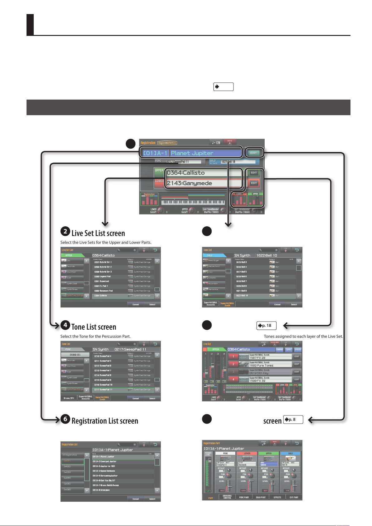
Registration Screen
This is the main screen that appears when you turn on the power. It shows the name of the currently selected Registration, the sound and volume of
each Part, and the split status.
1
p. xx
.
2
Live Set List screen
Select the Live Sets for the Upper and Lower Parts. Select the Tone for the Solo Part.
4
Tone List screen
Select the Tone for the Percussion Part. View the name and volume of the Tones assigned to each layer of the Live Set.
3
Tone List screen
5
Live Set screen
p. 18
6
Registration List screen
Select a Registration from a list. View the Registration’s volume, and settings such as the volume and pan of
7
Registration Part screen
each Part.
p. 8
3
Page 4
Navigating Between Screens
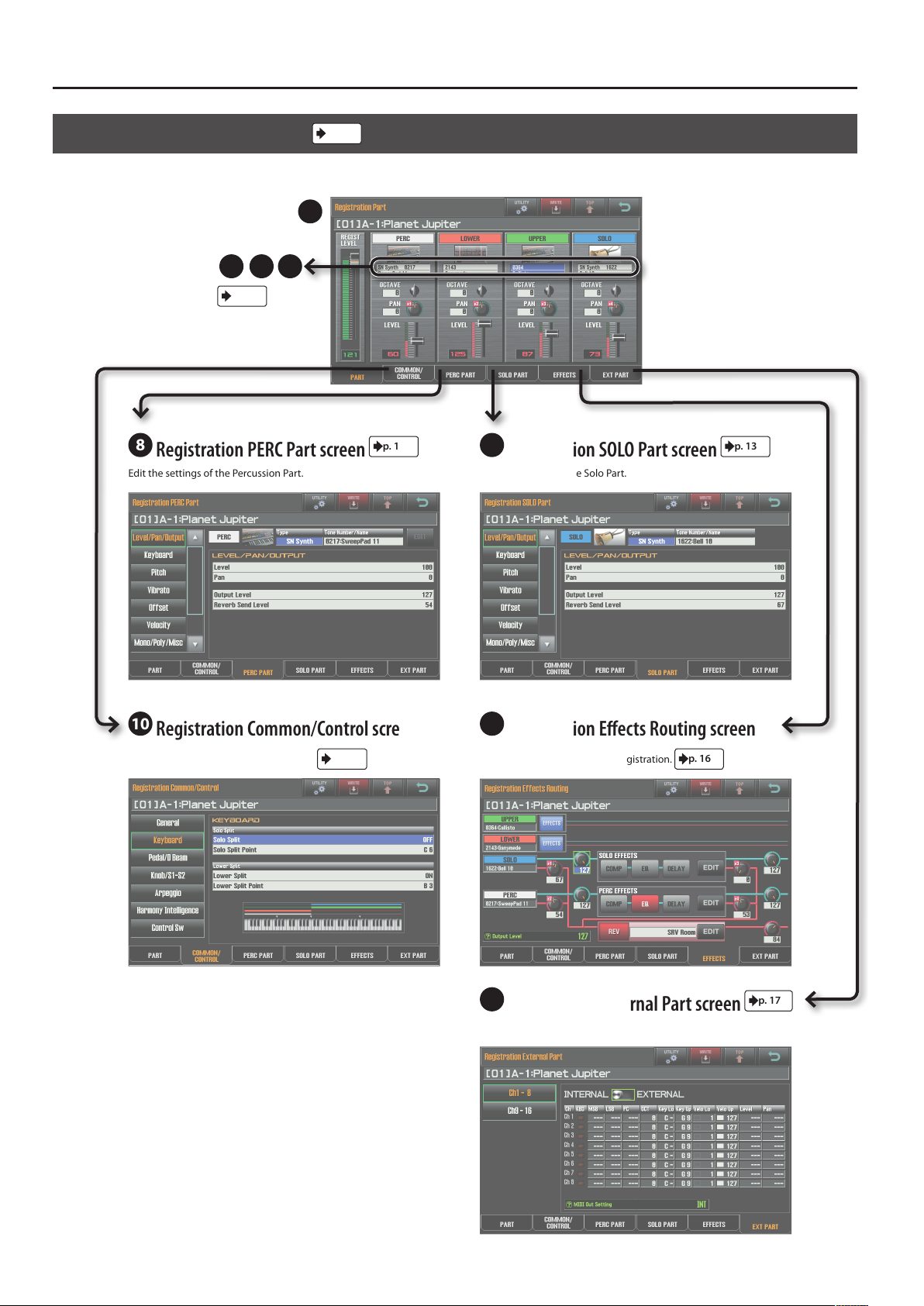
Registration Part Screen
Here you can view the volume of the Registration, and the volume and pan settings of each Part.
p. 8
7
432
p. 3
8
Registration PERC Part screen
Edit the settings of the Percussion Part. Edit the settings of the Solo Part.
p. 13
9
Registration SOLO Part screen
p. 13
10
Registration Common/Control screen
Make overall settings for the Registration.
p. 8
11
Registration Eects Routing screen
Edit the eect settings for the Registration.
12
Registration External Part screen
Edit Part settings for an external MIDI device.
p. 16
p. 17
4
Page 5
Navigating Between Screens
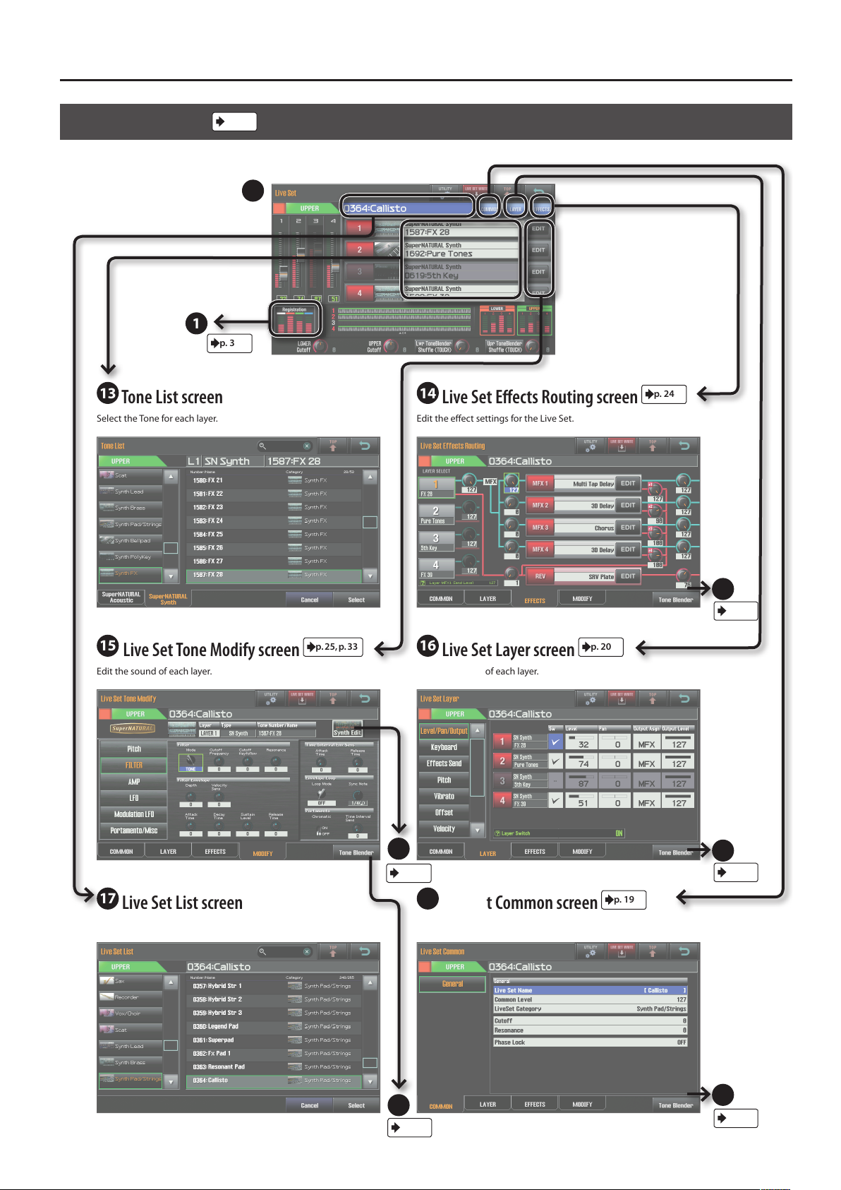
Live Set Screen
View the name and volume of the Tones assigned to each layer of the Live Set.
p. 18
5
1
p. 3
13
Tone List screen
Select the Tone for each layer. Edit the eect settings for the Live Set.
14
Live Set Eects Routing screen
p. 24
15
Live Set Tone Modify screen
Edit the sound of each layer. Edit the settings of each layer.
p. 25, p. 33
16
Live Set Layer screen
21
p. 37
17
Live Set List screen
Select a Live Set. Make overall settings for the Live Set.
18
Live Set Common screen
24
p. 36
p. 20
24
p. 36
p. 19
24
p. 36
24
p. 36
5
Page 6
Navigating Between Screens
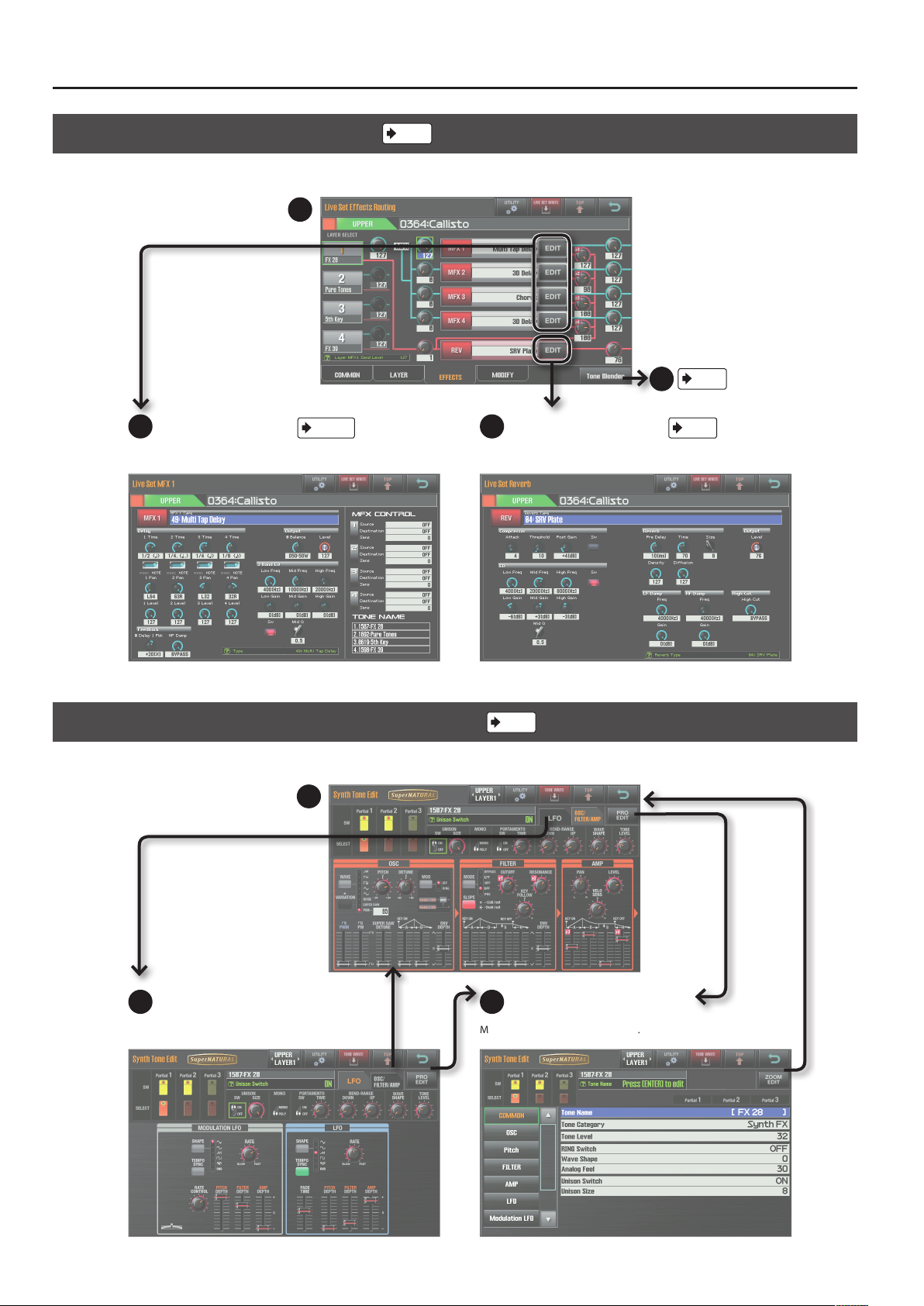
Live Set Eects Routing Screen
Edit the eect settings for the Live Set.
14
19
Live Set MFX screen
Edit the parameters of each multi-eect. Edit the reverb parameters of the Live Set.
p. 42–
p. 24
20
Live Set Reverb screen
24
p. 36
p. 79
Synth Tone Edit (OSC/FILTER/AMP) Screen
Edit the oscillator, lter, and amp settings of the SuperNATURAL Synth Tone.
21
22
LFO screen
Edit the Tone’s LFO settings. Make detailed settings for the Tone.
p. 37
23
Pro Edit screen
6
Page 7
Navigating Between Screens
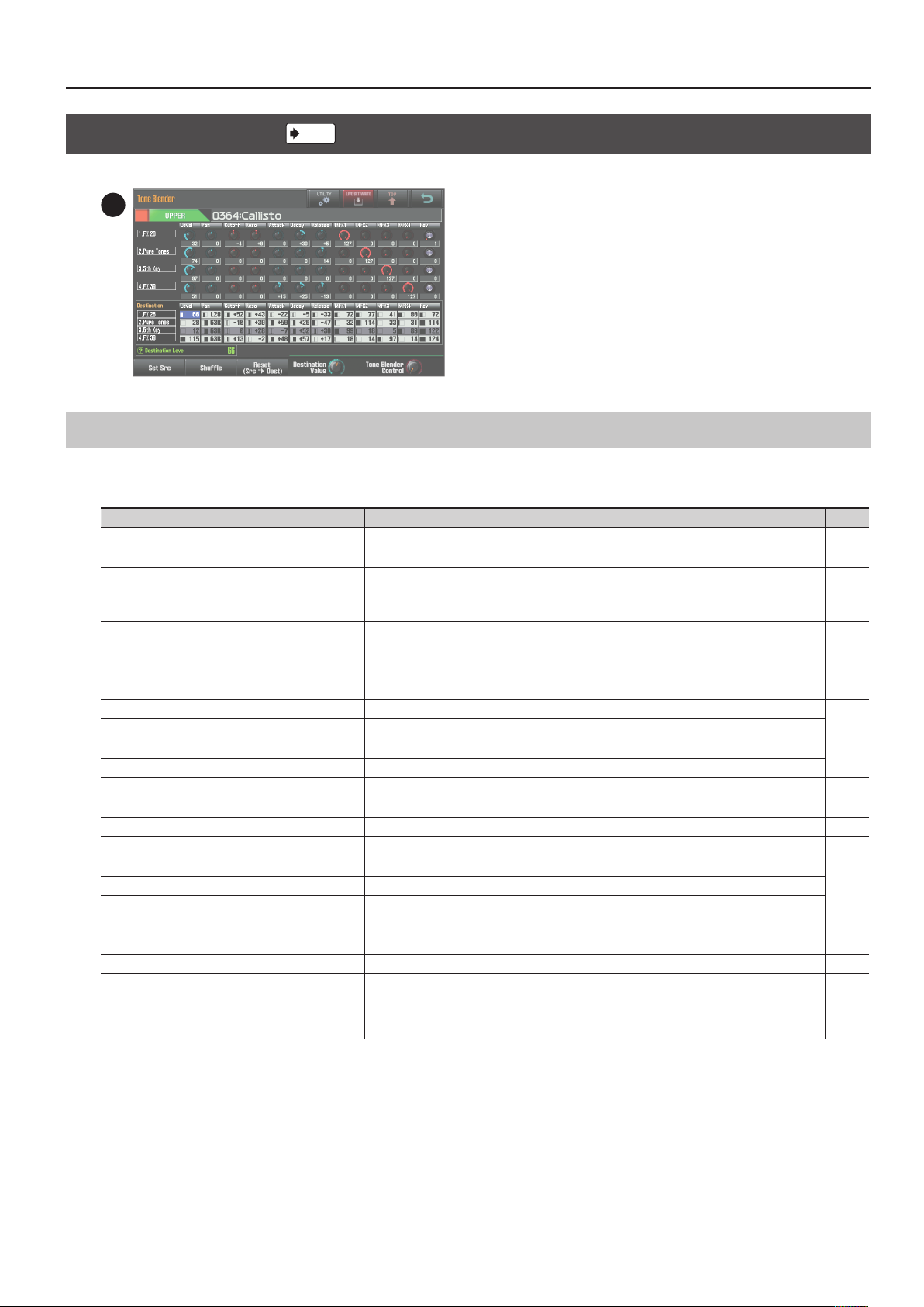
Tone Blender Screen
Simultaneously edit multiple parameters of the Live Set.
p. 36
24
List of Shortcuts
By holding down the [SHIFT] button and pressing another button, you can edit the settings of the button you pressed; i.e., this is a shortcut to the
corresponding editing screen.
Shortcut Description Page
[SHIFT] + [ASSIGNABLE] Accesses the D Beam Assign setting screen. p. 9
[SHIFT] + [S1] (or S2) Accesses the Switch S1 Assign (or Switch S2 Assign) setting screen. p. 9
[SHIFT] + [HOLD]
[SHIFT] + ARPEGGIO LOWER [ON/OFF]
[SHIFT] + ARPEGGIO UPPER [ON/OFF]
[SHIFT] + [HARMONY INTELLIGENCE] Accesses the Harmony Type setting screen. p. 12
Accesses the arpeggiator setting screen. p. 10
[SHIFT] + [SPLIT] Accesses the Lower Split Point setting screen. p. 8
[SHIFT] + [SOLO SPLIT] Accesses the Solo Split Point setting screen. p. 8
[SHIFT] + LOWER [BASS] Accesses the Synth Tone Edit screen for layer 1 of the Live Set assigned to the Lower Part.
[SHIFT] + LOWER [PAD] Accesses the Synth Tone Edit screen for layer 2 of the Live Set assigned to the Lower Part.
[SHIFT] + LOWER [CHOIR] Accesses the Synth Tone Edit screen for layer 3 of the Live Set assigned to the Lower Part.
[SHIFT] + LOWER [STRINGS] Accesses the Synth Tone Edit screen for layer 4 of the Live Set assigned to the Lower Part.
[SHIFT] + LOWER [SYNTH BRASS] Accesses the Live Set Common screen of the Lower Part. p. 19
[SHIFT] + LOWER [WOOD WINDS] Accesses the Live Set Layer screen of the Lower Part. p. 20
[SHIFT] + LOWER [OTHER] Accesses the Live Set Eects Routing screen of the Lower Part. p. 24
[SHIFT] + UPPER [PIANO] Accesses the Synth Tone Edit screen for layer 1 of the Live Set assigned to the Upper Part.
[SHIFT] + UPPER [E. PIANO] Accesses the Synth Tone Edit screen for layer 2 of the Live Set assigned to the Upper Part.
[SHIFT] + UPPER [CLAV] Accesses the Synth Tone Edit screen for layer 3 of the Live Set assigned to the Upper Part.
[SHIFT] + UPPER [COMBO ORGAN] Accesses the Synth Tone Edit screen for layer 4 of the Live Set assigned to the Upper Part.
[SHIFT] + UPPER [VIBES/MARIMBA] Accesses the Live Set Common screen of the Upper Part. p. 19
[SHIFT] + UPPER [ACCORDION/HARMONICA] Accesses the Live Set Layer screen of the Upper Part. p. 20
[SHIFT] + UPPER [OTHER] Accesses the Live Set Eects Routing screen of the Upper Part. p. 24
Accesses the Tone Blender screen.
[SHIFT] + rotate the [E1]–[E4] knobs
* This function is available in Registration screens and Live Set screens, and requires that Tone
Blender (CC79) be assigned as one of the Knob E1 Assign–Knob E4 Assign settings (“Registration
Common/Control Screen” (P. 8)).
p. 37
p. 37
p. 36
7
Page 8
Parameter List
The following icons indicate how the parameters are saved.
Registration
Live Set
: Saved as Registration parameters.
: Saved as Live Set parameters.
Tone
: Saved as Synth Tone parameters.
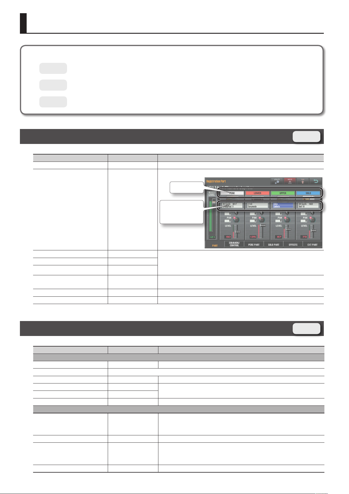
Registration Part Screen
Parameter Value Explanation
REGIST LEVEL 0–127 Volume of the registration. Use this to adjust the volume balance between registrations.
Part on/o switch.
Part Switch
Part Switch OFF, ON
Live Set Number
Tone Type
Tone Number
Registration
Live Set Number - Assigns a sound to the part. A Live Set is assigned to the upper part and the lower part, and a
Tone Type -
Tone Number -
OCTAVE -3– +3
PAN L64–0–63R Part panning (left/right position).
LEVEL 0–127 Part volume. This is used mainly to adjust the volume balance between parts.
Tone is assigned to the solo part and the percussion part.
* The SuperNATURAL acoustic tone 0028:TW Organ can’t be assigned to the solo part or
percussion part.
Part (keyboard) pitch in one-octave steps.
This can’t be specied for a part to which manual percussion is assigned.
Registration Common/Control Screen
Parameter Value Explanation
General tab
Registration Name - Name of the registration.
Registration Level Described in the Registration Part screen’s “REGIST LEVEL” (p. 8).
Tempo 20–250 Tempo for the arpeggio, LFO, eects, metronome, etc.
Transpose Switch OFF, ON
Transpose Value -5 (G)– +6 (F#)
Octave Shift -3– +3 Species the keyboard pitch in octave steps.
Keyboard tab
Solo Split OFF, ON
Solo Split Point F1–G7 Species the solo split point.
Lower Split OFF, ON
Lower Split Point E1–F#7 Species the lower split point.
8
Species the keyboard pitch in semitone steps.
If this is on, the sound of the solo part will be sounded by keys to the right of the solo split
point, and the sound of the upper part will be sounded by those to the left.
The solo split point key will be the lowest note of the solo part (it will be included in the solo
part).
If this is on, the sound of the upper part will be sounded by keys to the right of the lower split
point, and the sound of the lower part will be sounded by those to the left.
The lower split point key will be the highest note of the lower part (it will be included in the
lower part).
Registration
Page 9
Parameter Value Explanation
Pedal/D Beam tab
This selects the function that’s controlled when the D Beam controller’s ASSIGNABLE button is on.
OFF No function is assigned.
D Beam Assign
Control Pedal 1 Assign
Control Pedal 2 Assign
Knob/S1-S2 tab
Knob E1 Assign
Knob E2 Assign
Knob E3 Assign
Knob E4 Assign
CC01–31, 33–95 Controller numbers 1–31, 33–95
AFTERTOUCH Aftertouch
BEND UP The same eect as when the pitch bend lever is moved to the right.
BEND DOWN The same eect as when the pitch bend lever is moved to the left.
These select the functions that are controlled by pedals connected to the FOOT PEDAL CTRL 1 and 2 jacks.
Control Pedal 1 Assign and Control Pedal 2 Assign settings are enabled when the system parameters Control Pedal 1 Assign
Source or Control Pedal 2 Assign Source are set to REGISTRATION.
OFF No function is assigned.
CC01–31, 33–95 Controller numbers 1–31, 33–95
AFTERTOUCH Aftertouch
BEND UP The same eect as when the pitch bend lever is moved to the right.
BEND DOWN The same eect as when the pitch bend lever is moved to the left.
These select the functions that are assigned to E1–E4. You can specify whether the setting will apply to Upper or Lower.
No Assign No function is assigned.
Cuto Adjust the Live Set Common Cuto.
Resonance Adjust the Live Set Common Resonance.
Attack Time Oset Adjust the Live Set Layer Attack Time Oset.
Decay Time Oset Adjust the Live Set Layer Decay Time Oset.
Release Time Oset Adjust the Live Set Layer Release Time Oset.
Vibrato Rate Adjust the Live Set Layer Vibrato Rate.
Vibrato Depth Adjust the Live Set Layer Vibrato Depth.
Vibrato Delay Adjust the Live Set Layer Vibrato Delay.
CC05 (Porta Time)
CC07 (Volume)
CC10 (Pan)
CC16 (Modify-1)
CC17 (Modify-2)
CC18 (Modify-3)
CC19 (Modify-4)
CC65 (PortamentoSw)
CC71 (Resonance)
CC72 (Release Time)
CC73 (Attack Time)
CC74 (Cuto)
CC75 (Decay Time)
CC76 (Vib Rate)
CC77 (Vib Depth)
CC78 (Vib Delay)
CC79 (Tone Blender)
CC80 (Variation-1)
CC81 (Variation-2)
CC82 (Variation-3)
CC83 (Variation-4)
CC91 (Reverb)
Transmit the corresponding control change.
Parameter List
9
Page 10
Parameter List
Parameter Value Explanation
These select the functions that are assigned to the [S1]/[S2] buttons.
Some SuperNATURAL acoustic tones allow you to use control changes to modify the tone character of the sound or switch to
a dierent variation sound. For details, refer to “Control Change Assign List” (p. 80).
OFF
CC01 (Modulation)
CC02 (Breath)
CC03
CC04 (Foot Type)
CC11 (Expression)
CC12
CC13
CC14
CC15
CC16 (Modify-1)
CC17 (Modify-2)
CC18 (Modify-3)
CC19 (Modify-4)
CC20
CC21
CC22
Switch S1 Assign
Switch S2 Assign
Switch S1 Type
Switch S2 Type
Arpeggio tab
Upper Switch
Lower Switch
Style P001–P128, U001–U128
Hold OFF, ON Turns the arpeggio hold function on/o.
Variation 1–
CC23
CC24
CC25
CC26
CC27
CC28
CC29
CC30
CC31
CC64 (Hold-1)
CC65 (PortamentoSw)
CC66 (Sostenuto)
CC67 (Soft)
CC68 (Legato Sw)
CC69 (Hold-2)
CC79 (Tone Blender)
CC80 (Variation-1)
CC81 (Variation-2)
CC82 (Variation-3)
CC83 (Variation-4)
AFTERTOUCH Transmit aftertouch.
MONO/POLY Transmit a control change.
LATCH Switch the setting on/o each time you press the button.
MOMENTARY The setting will be on while the button is held down, and o when released.
OFF, ON Turns the arpeggiator on/o.
Transmit a control change.
Transmit a control change.
If a SuperNATURAL acoustic tone is selected, a specic eect will be applied (p. 80).
Transmit a control change.
Transmit a control change.
If a SuperNATURAL acoustic tone is selected, a specic eect will be applied (p. 80).
Species the basic style of the arpeggio.
You can create your own original arpeggio style by importing an SMF into an arpeggio style.
For details, refer to JUPITER-80 Owner’s Manual “Creating an Arpeggio Style from a MIDI File
(Import).”
Each arpeggio style provides several variations (patterns). Here you can select the variation
number. The number of variations will depend on the arpeggio style.
10
Page 11
Parameter Value Explanation
Choose one of the following to specify the order in which the notes of the chord you play will be sounded.
UP The notes will be sounded from the lowest to the highest note you play.
DOWN The notes will be sounded from the highest to the lowest note you play.
UP&DOWN
RANDOM The notes you play will be sounded in random order.
NOTE ORDER
Motif
Velocity
Oct Range -3– +3
Accent 0–100%
GLISSANDO
CHORD All of the notes you play will sound simultaneously.
AUTO1
AUTO2
PHRASE
REAL,
1–127
The notes will be sounded from the lowest to the highest note, and then back down to the
lowest note.
The notes you play will be sounded in the order you played them. You can create a melody line
by playing the notes in the appropriate order. The order of up to 128 notes can be remembered.
A chromatic glissando will be sounded upward and then downward repeatedly between the
lowest and highest notes you played. Play two notes; the lowest and highest desired notes.
The timing at which each note will sound is assigned automatically, starting at the lowest note
you play.
The timing at which each note will sound is assigned automatically, starting at the highest note
you play.
Play only one key; a phrase based on the pitch of that key will be sounded. If you play more than
one key, the last key you play will take priority.
Species the loudness at which the notes you play will be sounded. If you want the notes to be
sounded at the velocity with which you actually struck the key, choose “REAL.” If you want the
notes to be sounded at a xed velocity regardless of how strongly you struck the key, specify
that value (1–127).
Species the range in octaves in which the arpeggio will be sounded. Choose “0” if you want
only the notes you play to be sounded.
Choose “+1” if you want the notes of the chord you played as well as the same notes one octave
higher to be sounded. Choose “-1” if you want the notes of the chord you played as well as the
notes one octave lower to be sounded.
Modies the groove of the performance by adjusting the strength of the accents and the
duration of the notes. The “100%” setting produces the strongest sense of groove.
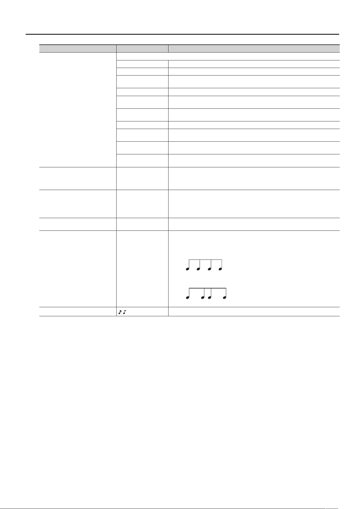
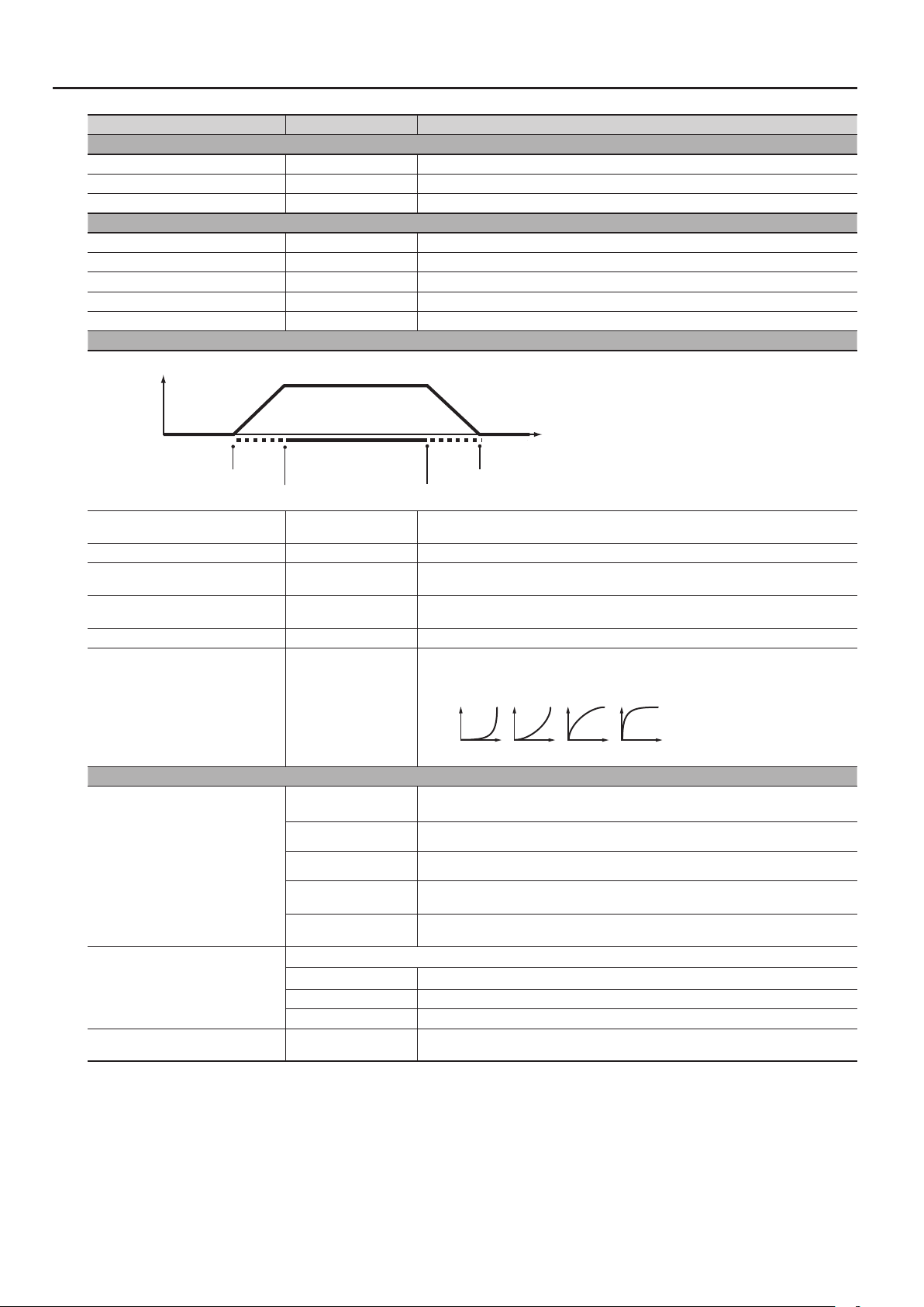
Produces a shue rhythm by adjusting the timing of the notes.
With the “50%” setting, notes will be sounded at equal intervals. As this value is increased, the
result will be more like dotted notes.
Shue Rate = 50%
Parameter List
Shue Rate 0–100%
Shue Resolution
,
50 5050 50
Shue Rate = 90%
90 10 90 10
Species the timing (as a note value) at which the notes will be heard.
11
Page 12
Parameter List
Parameter Value Explanation
Harmony Intelligence tab
Harmony Switch OFF, ON Turns the harmony intelligence on/o.
ORGAN Harmony appropriate for organ sounds will be produced.
Harmony typical of big band jazz will be produced.
This is appropriate for brass sounds.
Block chord harmony will be produced.
This is appropriate for piano or mallet sounds.
Harmony appropriate for hymns will be produced.
This is appropriate for choir sounds.
Simple duet harmony will be produced.
This is appropriate for brass sounds.
Combination harmony will be produced.
This is appropriate for brass or wind sounds.
Open chord harmony will be produced.
This is appropriate for guitar sounds.
Flamboyant show-type harmony will be produced.
This is appropriate for organ sounds.
Gospel harmony will be produced.
This is appropriate for organ or choir sounds.
For each controller, you can specify whether MIDI messages will be transmitted to the part (ON)
or not transmitted (OFF).
If INTERNAL is set for “MIDI Out Setting” (p. 17), these settings also apply to the MIDI output.
Harmony Type
Control Sw tab
Bend (Bender)
Mod (Modulation)
S1 (Switch S1)
S2 (Switch S2)
Hold (Hold Pedal)
Pedal1 (Control Pedal 1)
Pedal2 (Control Pedal 2)
Aft (Aftertouch)
DBeam (D Beam)
BIG BAND
STRINGS Harmony typical of a string ensemble will be produced. This is appropriate for string sounds.
BLOCK
HYMN
TRADITIONAL Two notes of harmony will be added to the notes you play.
DUET
COMBO
COUNTRY
BROADWAY
GOSPEL
OCTAVE1 The note you play will be layered with a note one octave lower.
OCTAVE2 The note you play will be layered with a note two octaves lower.
1NOTE One note of harmony will be added to the note you play.
2NOTES Two notes of harmony will be added to the note you play.
3NOTES Three notes of harmony will be added to the note you play.
4NOTES Four notes of harmony will be added to the note you play.
OFF, ON
12
Page 13
Parameter List
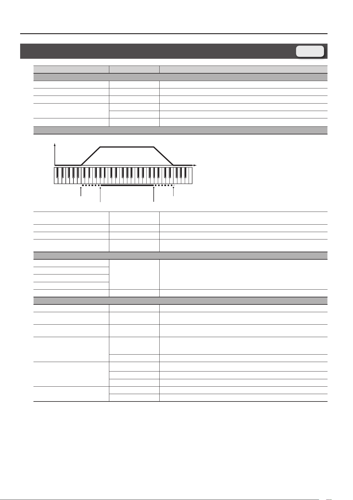
Keyboard Range Lower
Keyboard Range Upper
Keyboard Fade Width Lower
Keyboard Fade Width Upper
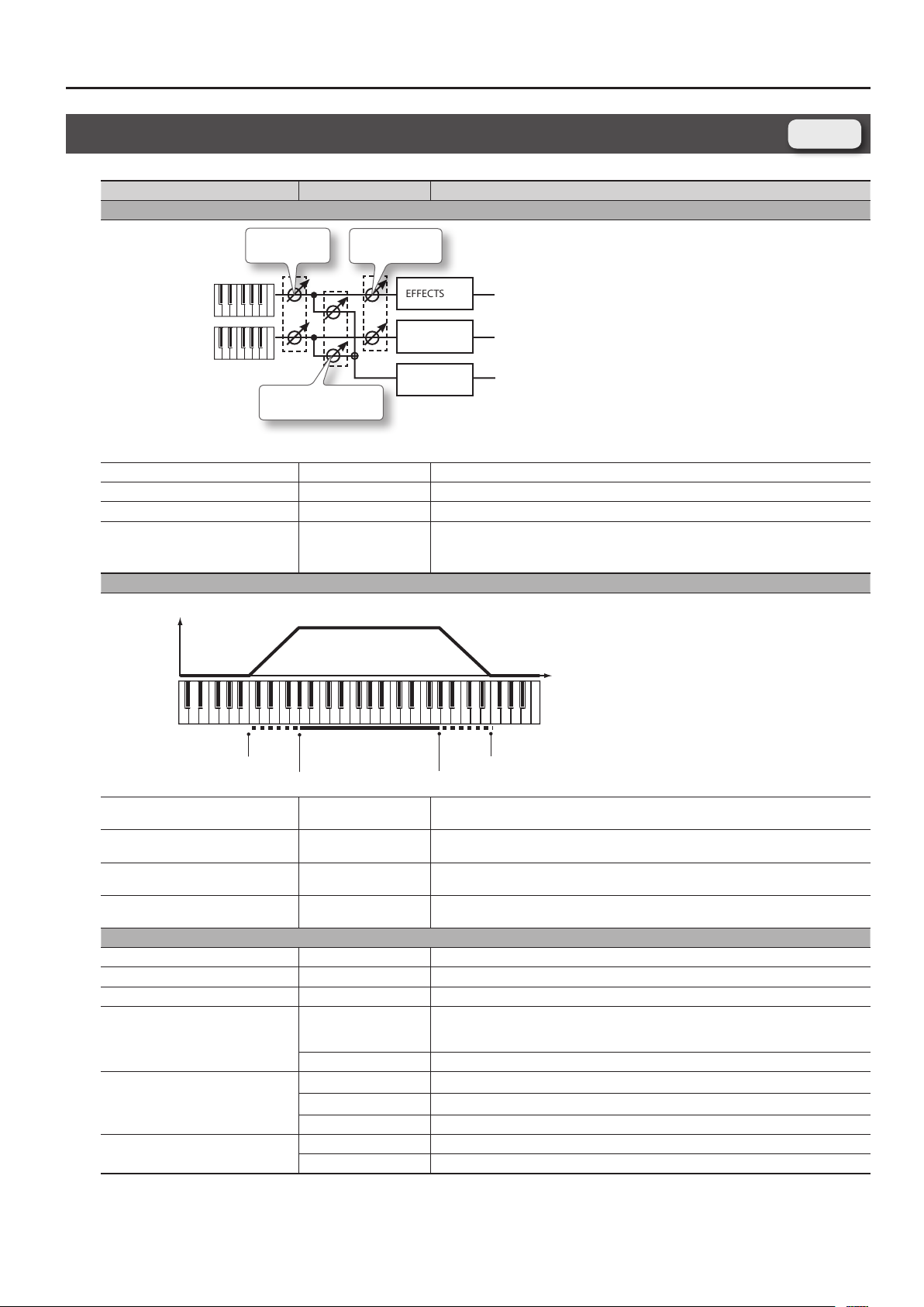
Registration PERC Part Screen, Registration SOLO Part Screen
Parameter Value Explanation
Level/Pan/Output tab
Level, Pan
SOLO Part
PERC Part
Reverb Send Level
Level 0–127 Volume of the part.
Pan L64–0–63R Part panning.
Output Level 0–127 Volume at which the part’s sound is sent to the eect.
Reverb Send Level 0–127 Volume at which the part’s sound is sent to the reverb.
Output Level
EFFECTS
EFFECTS
REV
Registration
Keyboard tab
Level
Pitch
Keyboard Fade Width Upper *5 0–127
Keyboard Range Upper *5
Keyboard Range Lower *5
Keyboard Fade Width Lower *5 0–127
Pitch tab
Octave Shift *6 -3– +3 Pitch of the part sound (in 1-octave units)
Coarse Tune -48– +48 Pitch of the part sound (in semitones, +/-4 octaves)
Fine Tune -50– +50 Pitch of the part sound (in 1-cent steps; one cent is 1/100th of a semitone)
Pitch Bend Range
Portamento Switch *6, *9
Portamento Time *6
(Keyboard Range
Lower)–G9
C-–(Keyboard Range
Upper)
0–24
TONE The pitch bend range setting of the tone assigned to the part will be used.
OFF Portamento will not be applied.
ON Portamento will be applied.
TONE The portamento switch setting of the tone assigned to the part will be used.
0–127 Time over which the pitch change will occur when using portamento
TONE The portamento time setting of the tone assigned to the part will be used.
Determines what will happen to the part level when a note that’s higher than Key Range Upper
is played. If you don’t want the layer to sound at all, set this parameter to “0.”
Species the highest note that the layer will sound for each part.
Species the lowest note that the layer will sound for each part.
Determines what will happen to the part level when a note that’s lower than Key Range Lower is
played. If you don’t want the layer to sound at all, set this parameter to “0.”
Amount of pitch change in semitones (2 octaves) that will occur when the Pitch Bend Lever is
moved. The amount of change when the lever is tilted is set to the same value for both left and
right sides.
13
Page 14
Parameter List
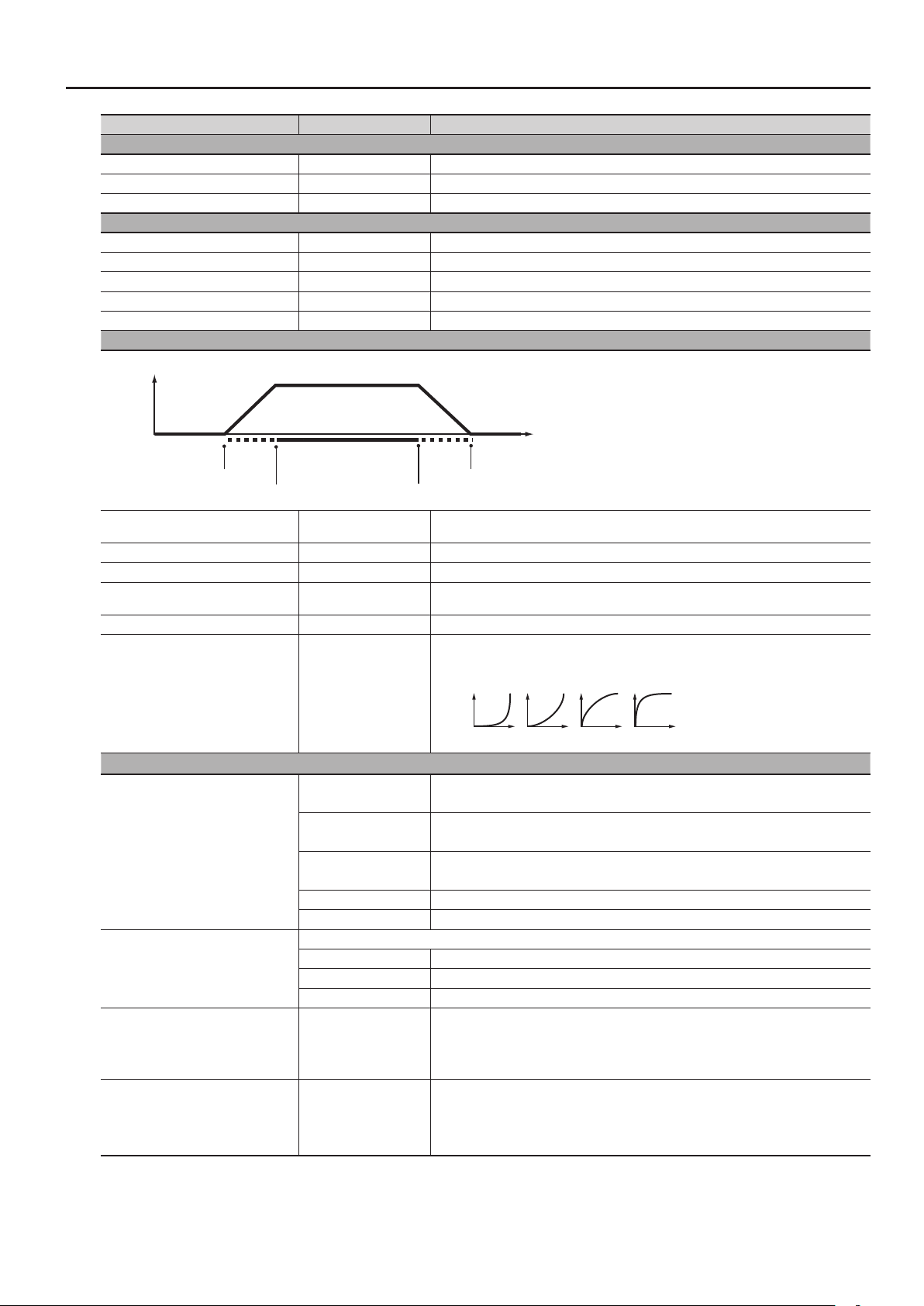
Velocity Range Lower
Velocity Range Upper
Velocity Fade Width Lower
Velocity Fade Width Upper
21 3 4
Parameter Value Explanation
Vibrato tab
Vibrato Rate -64– +63 For each part, adjust the vibrato speed
Vibrato Depth -64– +63 For each part, this adjusts the depth of the vibrato eect
Vibrato Delay -64– +63 For each part, this adjusts the time delay until the vibrato
Oset tab
Cuto Oset *2 -64– +63 Cuto frequency of the part
Resonance Oset *2 -64– +63 Resonance of the part
Attack Time Oset *2 -64– +63 Amp/Filter Envelope of the part Attack Time
Decay Time Oset *7 -64– +63 Amp/Filter Envelope of the part Decay Time
Release Time Oset *2 -64– +63 Amp/Filter Envelope of the part Release Time
Velocity tab
Level
Velocity
Velocity Fade Width Lower 0–127
Velocity Range Lower 1–(Velocity Range Upper) Species the lowest velocity at which the part will sound.
Velocity Range Upper
Velocity Fade Width Upper 0–127
Velocity Sens Oset -63– +63 Adjusts the velocity sensitivity. The higher the value, the greater the sensitivity.
Velocity Curve Type OFF, 1–4
Mono/Poly/Misc tab
Mono/Poly *6
Legato Switch *6
Voice Reserve 0–63, FULL
(Velocity Range
Lower)–127
MONO
POLY Chords can be played on the tone assigned to the part.
TONE The mono/poly setting of the tone assigned to the part will be used.
SOLO 1
SOLO 2
Legato refers to playing smoothly without a perceptible break between notes.
OFF Legato will not be applied to the part.
ON Legato will be applied to the part when you play single notes.
TONE The legato setting of the tone assigned to the part will be used.
Determines what will happen to the tone’s level when the tone is played at a velocity lower than
Velo Range Lower. If you don’t want the tone to sound at all, set this parameter to “0.”
Species the highest velocity at which the part will sound.
Determines what will happen to the tone’s level when the tone is played at a velocity greater
than Velo Range Upper. If you don’t want the tone to sound at all, set this parameter to “0.”
Velocity curve for each part.
Selects for each part one of the four following Velocity Curve types that best matches the touch
of the keyboard. Set this to “OFF” if you are using the keyboard’s own velocity curve.
The tone assigned to the part will only play monophonically.
The most recently played note will take priority.
The tone assigned to the part will only play monophonically.
The highest note will take priority.
The tone assigned to the part will only play monophonically.
The lowest note will take priority.
This setting species the number of voices that will be reserved for each part when more than
128 voices are played simultaneously.
14
Page 15
Parameter List
Parameter Value Explanation
Rx Filter1 tab
Receive Bender
Receive Polyphonic Key Pressure *6
Receive Channel Pressure *6
Receive Modulation (CC01) *6
Receive Expression (CC11)
Receive Hold-1 (CC64)
Rx Filter2 tab
Receive Breath Type (CC02) *8
Receive Foot Type (CC04) *8
Receive Portamento (CC05, CC65) *6
Receive Filter Oset (CC71, CC74)
Receive Envelope Oset
(CC72, CC73, CC75)
Receive Reverb Send (CC91)
Receive Modify (CC16-19) *6
Receive Variation (CC80-83) *6
*2 This has no eect on the SuperNATURAL acoustic tones Concert Grand (0001)–Honky-tonk (0009) and TW Organ (0028). Also, the eect may be dicult to notice
for some SuperNATURAL acoustic tones.
*5 This has no eect if a manual percussion sound is assigned. Manual percussion is played using the leftmost fteen notes of the keyboard.
*6 This has no eect if a manual percussion or Drums/SFX sound is assigned.
*7 This has no eect on SuperNATURAL acoustic tones other than Vibraphone (0026), Marimba (0027), Timpani (0049), Steel Drums (0077), APS Vibraphone (0078), APS
Marimba (0079), APS Timpani (0094), and APS Steel Drums (0117).
*8 This has no eect if a SuperNATURAL synth tone, manual percussion, or Drums/SFX sound is assigned.
*9 This has no eect on the SuperNATURAL acoustic tones TW Organ (0028), Timpani (0049), and APS Timpani (0094).
OFF, ON
OFF, ON
Species whether the part will receive messages of a specic MIDI part (ON) or will not receive
them (OFF).
Species whether the part will receive messages of a specic MIDI part (ON) or will not receive
them (OFF).
15
Page 16

Parameter List
Registration Eects Routing Screen
Parameter Value Explanation
Reverb Switch OFF, ON Turns the reverb on/o for the solo and percussion parts.
Output Level Described in “Output Level” (p. 13) for the Registration PERC Part screen and Registration SOLO Part.
Reverb Send Level Described in “Reverb Send Level” (p. 13) for the Registration PERC Part screen and Registration SOLO Part screen.
Comp Switch
OFF, ON Turns each eect on/oEQ Switch
Delay Switch
Eects Reverb Send Level 0–127 Level of the signal sent from the eect to the reverb
Eects Output Level 0–127 Output level of the eect
Reverb Level 0–127 Output level of the reverb
SOLO EFFECTS, PERC EFFECTS
COMP tab
Comp Switch OFF, ON Compressor switch for the solo and percussion parts
Attack 0–127
Threshold 0–127 Adjusts the volume at which compression begins
Post Gain 0– +18dB Adjusts the output gain.
Low Gain -15– +15dB Gain of the low range
High Gain -15– +15dB Gain of the high range
Comp Level 0–127 Output Level
EQ tab
EQ Switch OFF, ON Equalizer switch for the solo and percussion parts
Low Freq 200, 400Hz Frequency of the low range
Low Gain -15– +15dB Gain of the low range
Mid1 Freq 200–8000Hz Frequency of the middle range 1
Mid1 Gain -15– +15dB Gain of the middle range 1
Mid1 Q 0.5, 1.0, 2.0, 4.0, 8.0
Mid2 Freq 200–8000Hz Frequency of the middle range 2
Mid2 Gain -15– +15dB Gain of the middle range 2
Mid2 Q 0.5, 1.0, 2.0, 4.0, 8.0
High Freq 2000, 4000, 8000Hz Frequency of the high range
High Gain -15– +15dB Gain of the high range
EQ Level 0–127 Output Level
DELAY tab
Delay Switch OFF, ON Delay switch for the solo and percussion parts
Delay Left
Delay Right
Phase Left
Phase Right
Feedback Mode NORMAL, CROSS
Feedback -98– +98%
HF Damp 200–8000Hz, BYPASS Adjusts the frequency above which sound fed back to the eect is ltered out. (BYPASS: no cut)
Low Gain -15– +15dB Gain of the low range
0–1300msec,
note (p. 86)
Phase of the left delay sound
NORMAL Non-inverted
INVERSE Inverted
Phase of the right delay sound
NORMAL Non-inverted
INVERSE Inverted
Sets the time from when the input exceeds the Threshold until the volume starts being
compressed
Width of the middle range 1
Set a higher value for Q to narrow the range to be aected.
Width of the middle range 2
Set a higher value for Q to narrow the range to be aected.
Adjusts the time until the delay sound is heard.
Selects the way in which delay sound is fed back into the eect.
See the gures “43 : DELAY” (p. 63).
Adjusts the amount of the delay sound that’s fed back into the eect. (Negative values invert
the phase.)
Registration
16
Page 17
High Gain -15– +15dB Gain of the high range
Balance D100:0W–D0:100W Volume balance between the direct sound (D) and the delay sound (W )
Delay Level 0–127 Output Level
Reverb
For details on the reverb eect, refer to “Reverb Parameters” (p. 79).
Parameter List
Registration External Part Screen
Parameter Value Explanation
Ch1-8 tab, Ch9-16 tab
MIDI output settings
MIDI Out Setting
KBD (Keyboard Switch) OFF, ON MIDI channels that are turned on will be output.
MSB (External Bank Select MSB)
LSB (External Bank Select LSB)
PC (Program Change) 1–128, ---
OCT (Part Octave Shift) -3– +3 Species the pitch of each channel in steps of an octave.
Key Lo (Keyboard Range Lower) C-– (Key Up) Species the bottom key of the key range for each channel.
Key Up (Keyboard Range Upper) (Key Lo)–G9 Species the top key of the key range for each channel.
Velo Lo (Velocity Range Lower) 1– (Velo Up) Species the lower limit of the velocity range for each channel.
Velo Up (Velocity Range Upper) (Velo Lo)–127 Species the upper limit of the velocity range for each channel.
Level (External Level) 0–127, ---
Pan (External Pan) L64–0–63R, ---
INT (INTERNAL) MIDI output will occur according to the part settings.
EXT (EXTERNAL)
0–127, ---
MIDI output will occur according to the settings in the Registration External Part screen.
This is convenient when using the JUPITER-80 as a master keyboard.
If you want a bank select number and program change number to be transmitted when you
switch registrations, specify the desired values here.
If you don’t want these to be transmitted, choose “---”.
If you want a volume message to be transmitted when you switch registrations, specify its value
here. If you don’t want these to be transmitted, choose “---”.
If you want a pan message to be transmitted when you switch registrations, specify its value
here. If you don’t want these to be transmitted, choose “---”.
Registration
17
Page 18
Parameter List
Live Set Screen
Parameter Value Explanation
Volume of each layer. This setting’s main purpose is to adjust the volume balance between layer.
Level 0–127
Layer Switch OFF, ON Layer on/o setting
Tone Type
Tone Number 0001–
SuperNATURAL Acoustic,
SuperNATURAL Synth
Selects the type of tone.
Selects the tone.
* The SuperNATURAL acoustic tone 0028:TW Organ can be assigned only to layer 1 of the upper part
Live Set
and lower part.
18
Page 19
Parameter List
Live Set Common Screen
Parameter Value Explanation
General tab
Live Set Name - Name of the live set.
Common Level 0–127 Adjusts the overall volume of the live set.
No assign, Ac.Piano, Pop
Piano, E.Grand Piano,
E.Piano1, E.Piano2, E.Organ,
Pipe Organ, Reed Organ,
Harpsichord, Clav, Celesta,
Accordion, Harmonica, Bell,
Mallet, Ac.Guitar, E.Guitar,
Dist.Guitar, Ac.Bass, E.Bass,
Synth Bass, Plucked/Stroke,
Solo Strings, Ensemble
LiveSet Category
Cuto *2 -64– +63 Species the cuto frequency for the entire live set.
Resonance *2 -64– +63 Species the resonance for the entire live set.
Phase Lock *3 OFF, ON
Strings, Orchestral, Solo
Brass, Ensemble Brass,
Wind, Flute, Sax, Recorder,
Vox/Choir, Scat, Synth Lead,
Synth Brass, Synth Pad/
Strings, Synth Bellpad,
Synth PolyKey, Synth FX,
Synth Seq/Pop, Phrase,
Pulsating, Beat&Groove,
Hit, Sound FX, Drums,
Percussion, Stack, Zone,
Distorted
Selects the category of the live set.
Turn this “ON” if you want to align the timing at which each layer produces sound.
If this is “ON,” all layers will sound simultaneously when all are ready.
This means that in some cases, it might take a moment from when the note message is received
until the sound is heard.
Turn this “ON” if necessary.
Live Set
*2 This has no eect on the SuperNATURAL acoustic tones Concert Grand (0001)–Honky-tonk (0009) and TW Organ (0028). Also, the eect may be dicult to notice
for some SuperNATURAL acoustic tones.
*3 This has no eect on the SuperNATURAL acoustic tone TW Organ (0028).
19
Page 20
Parameter List
Live Set Layer Screen
Parameter Value Explanation
Level/Pan/Output tab
Sw (Layer Switch) OFF, ON Layer on/o setting
Level 0–127 Volume of each layer. This setting’s main purpose is to adjust the volume balance between layer.
Pan L64–0–63R Left/right position of each layer
Output Assign
Output Level 0–127 Level of the signal that is sent to the output destination specied by Output Assign
Keyboard tab
Level
Fade Lower
Range Lower
Fade Lower (Key Fade Lower) *3 0–127
Range Lower (Key Range Lower) C-– (Range Upper) Species the lowest note that the layer will sound for each layer.
Range Upper (Key Range Upper) (Range Lower)–G9 Species the highest note that the layer will sound for each layer.
Fade Upper (Key Fade Upper) *3 0–127
Eects Send tab
MFX1 Send (Layer MFX1 Send Level)
MFX2 Send (Layer MFX2 Send Level)
MFX3 Send (Layer MFX3 Send Level)
MFX4 Send (Layer MFX4 Send Level)
Reverb Send (Reverb Send Level) 0–127 Level of the signal sent from the layer to reverb
Pitch tab
Octave (Octave Shift) -3– +3 Pitch of the layer’s sound (in 1-octave units)
Coarse (Coarse Tune) -48– +48
Fine (Fine Tune) *3 -50– +50
Bend Range (Pitch Bend Range)
Porta SW (Portamento Switch) *9
PortaTime (Portamento Time) *9
MFX Output in stereo via the MFX.
L+R Output in stereo from the OUTPUT jacks without passing through MFX.
Pitch
Fade Upper
Range Upper
Determines what will happen to the layer’s level when a note that’s lower than Key Range Lower
is played. If you don’t want the layer to sound at all, set this parameter to “0.”
Determines what will happen to the layer’s level when a note that’s higher than Key Range
Upper is played. If you don’t want the layer to sound at all, set this parameter to “0.”
0–127 Level of the signal sent from the layer to MFX 1–4
Pitch of the layer’s sound
(in semitones, +/-4 octaves)
Pitch of the layer’s sound
(in 1-cent steps; one cent is 1/100th of a semitone)
0–24
TONE The bend range setting specied by the tone will be used.
OFF Portamento will not be applied.
ON Portamento will be applied.
TONE The portamento switch setting of the tone assigned to the layer will be used.
0–127 Time over which the pitch change will occur when using portamento
TONE The portamento time setting of the tone assigned to the layer will be used.
Amount of pitch change in semitones (2 octaves) that will occur when the Pitch Bend Lever is
moved. The amount of change when the lever is tilted is set to the same value for both left and
right sides.
Live Set
20
Page 21
Parameter Value Explanation
21 3 4
Vibrato tab
Vib Rate (Vibrato Rate) *3 -64– +63 For each layer, adjust the vibrato speed
Vib Depth (Vibrato Depth) *3 -64– +63 For each layer, this adjusts the depth of the vibrato eect
Vib Delay (Vibrato Delay) *3 -64– +63 For each layer, this adjusts the time delay until the vibrato
Oset tab
Cuto (Cuto Oset) *2 -64– +63 Cuto frequency
Resonance (Resonance Oset) *2 -64– +63 Resonance
Attack Time (Attack Time Oset) *2 -64– +63 Amp/Filter Envelope of the layer Attack Time
Decay (Decay Time Oset) *7 -64– +63 Amp/Filter Envelope of the layer Release Time
Release (Release Time Oset) *2 -64– +63 Amp/Filter Envelope of the layer Decay Time
Velocity tab
Level
Velocity
Parameter List
Fade Lower
Range Lower
FadeLower (Velocity Fade Lower) *3 0–127
VeloLower (Velocity Range Lower) *3 1– (Upper) Species the lowest velocity at which the layer will sound.
VeloUpper (Velocity Range Upper) *3 (Lower)–127 Species the highest velocity at which the layer will sound.
FadeUpper (Velocity Fade Upper) *3 0–127
VeloSens (Velocity Sens Oset) *1 -63– +63 Adjusts the velocity sensitivity. The higher the value, the greater the sensitivity.
Curve (Velocity Curve Type) OFF, 1–4
Mono/Poly/Misc tab
MONO
POLY Chords can be played on the tone assigned to the layer.
Mono/Poly *3
TONE The mono/poly setting of the tone assigned to the layer will be used.
SOLO 1 The tone assigned to the layer will only play monophonically. The highest note will take priority.
SOLO 2 The tone assigned to the layer will only play monophonically. The lowest note will take priority.
Legato refers to playing smoothly without a perceptible break between notes.
Legato (Legato Switch) *1
LayerSection (Layer Section Switch) OFF, ON
VoiceRsv (Voice Reserve) 0–63, FULL
OFF Legato will not be applied to the layer.
ON Legato will be applied to the layer when you play single notes.
TONE The legato setting of the tone assigned to the layer will be used.
Range Upper
Fade Upper
Determines what will happen to the tone’s level when the tone is played at a velocity lower than
Velo Range Lower. If you don’t want the tone to sound at all, set this parameter to “0.”
Determines what will happen to the tone’s level when the tone is played at a velocity greater
than Velo Range Upper. If you don’t want the tone to sound at all, set this parameter to “0.”
Velocity curve for each layer
Selects for each layer one of the four following Velocity Curve types that best matches the touch
of the keyboard. Set this to “OFF” if you are using the keyboard’s own velocity curve.
The tone assigned to the layer will only play monophonically.
The most recently played note will take priority.
If this is on, you’ll be able to play the layer as part of a Section. By assigning wind or string
instruments to multiple layers, you can create the impression of a brass section or string section.
For details on how this works, refer to “LayerSection examples” (p. 23).
This parameter is valid for SuperNATURAL Acoustic wind instruments and string instruments
(with the exception of some ethnic sounds).
This setting species the number of voices that will be reserved for each layer when more than
128 voices are played simultaneously.
It is not possible for the settings of all layers to total an amount greater than 64. The remaining
number of available voices will be displayed at (rest=). Pay attention to this readout as you make
Voice Reserve settings.
21
Page 22
Parameter List
Parameter Value Explanation
Rx Filter1 tab
Bend (Receive Bender) *3
PAf (Receive Poly Key Press) *3
CAf (Receive Channel Press) *3
Mod (Receive Modulation: CC01) *3
Exp (Receive Expression: CC11) *3
Hold (Receive Hold-1: CC64) *3
Rx Filter2 tab
Breath (Receive Breath Type: CC02) *4
Foot (Receive Foot Type: CC04) *4
Porta (Receive Portamento: CC05, CC65)
*3
Filter (Receive Filter Oset: CC71, CC74)
*3
Env (Receive Envelope Oset: CC72,
CC73, CC75) *3
Reverb (Receive Reverb Send: CC91)
Modify (Receive Modify: CC16-19)
Vari (Receive Variation: CC80-83)
*1 This has no eect on SuperNATURAL acoustic tones other than Concert Grand (0001) through Honky-tonk (0009).
*2 This has no eect on the SuperNATURAL acoustic tones Concert Grand (0001)–Honky-tonk (0009) and TW Organ (0028).
Also, the eect may be dicult to notice for some SuperNATURAL acoustic tones.
*3 This has no eect on the SuperNATURAL acoustic tone TW Organ (0028).
*4 This has no eect on the SuperNATURAL acoustic tone TW Organ (0028) or on SuperNATURAL synth tones.
*7 This has no eect on SuperNATURAL acoustic tones other than Vibraphone (0026), Marimba (0027), Timpani (0049), Steel Drums (0077), APS Vibraphone (0078), APS
Marimba (0079), APS Timpani (0094), and APS Steel Drums (0117).
*9 This has no eect on the SuperNATURAL acoustic tones TW Organ (0028), Timpani (0049), and APS Timpani (0094).
OFF, ON Turn reception of specic MIDI messages on/o for each layer
OFF, ON Turn reception of specic MIDI messages on/o for each layer
22
Page 23
Parameter List
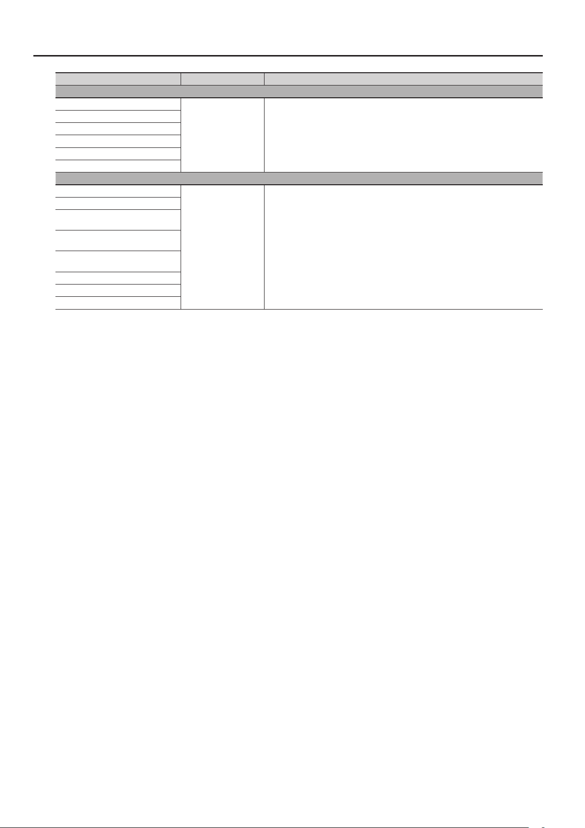
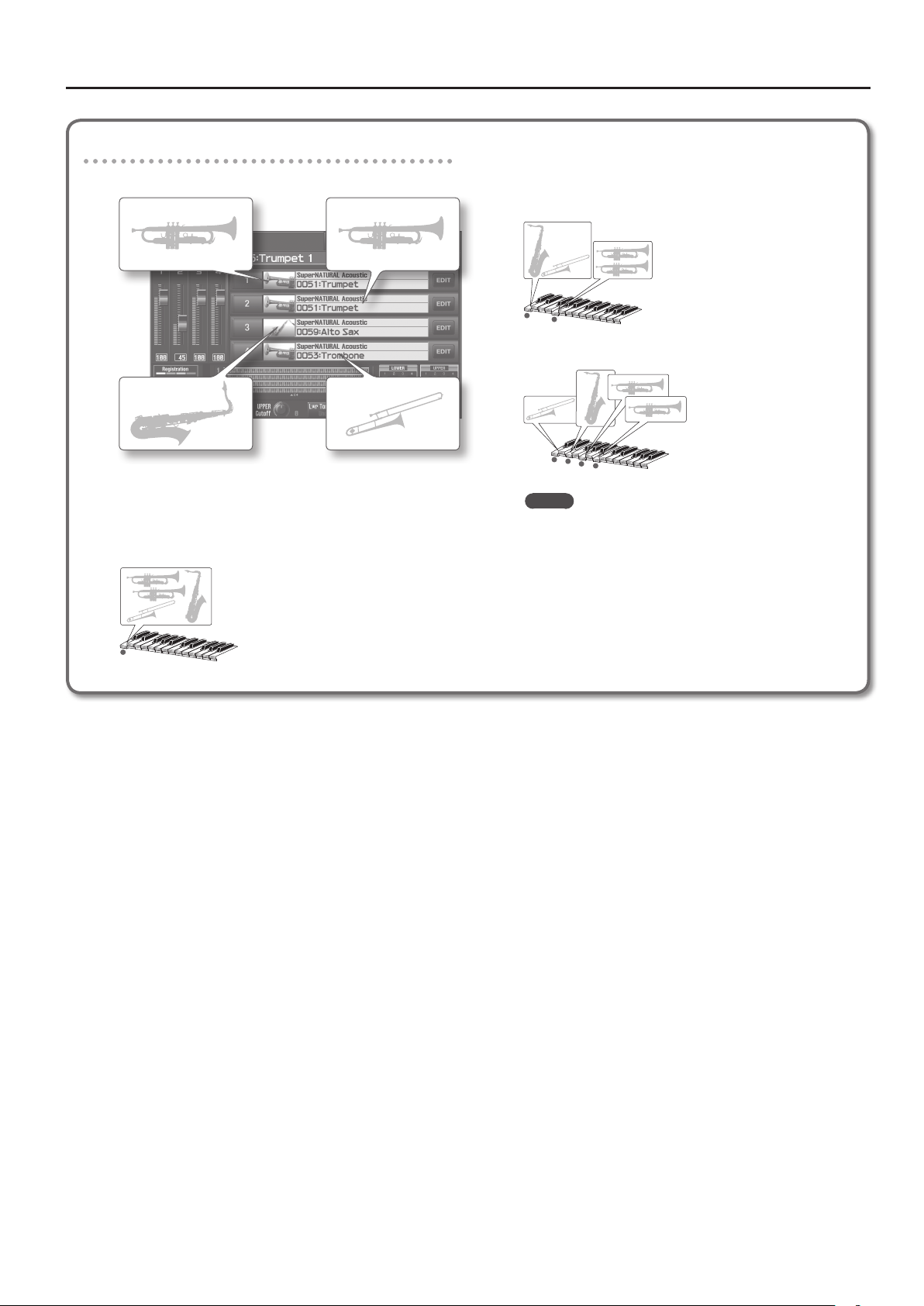
LayerSection examples
(LayerSection turned on for all layers)
Layer 1
When a single note is played
All instruments for which LayerSection is turned on will sound
at the same pitch.
Each instrument will be assigned to an appropriate octave.
Layer 2
Layer 4Layer 3
When multiple notes are played simultaneously
Each instrument will automatically be assigned to the
appropriate one of the notes you played.
• Example: Two notes played simultaneously
• Example: Four notes played simultaneously
MEMO
• When you turn LayerSection on and play multiple notes
simultaneously, the layers (sounds) will be assigned in the
order of their layer number, starting with the high note.
• The “Coarse Tune” setting is used only if LayerSection is
turned on and you’re playing a single note; it has no eect
when you play multiple notes simultaneously (chords).
For example, if you’re using brass section sounds, and want
the trombone to sound one octave lower for single notes,
but at the normal pitch for chords, set Coarse Tune to “-12.”
23
Page 24
Parameter List
Live Set Eects Routing Screen
Parameter Value Explanation
Output Level 0–127 Level of the signal sent to the output destination specied by Output Assign
Output Assign
Layer MFX1 Send Level
Layer MFX2 Send Level
Layer MFX3 Send Level
Layer MFX4 Send Level
Reverb Send Level 0–127 Level of the signal sent from each layer to the reverb
MFX Sw OFF, ON Multi-eects on/o
Type 0–76
MFX Output Level 0–127 Volume of the sound that has been processed by the multi-eect
MFX Reverb Send Level 0–127 Amount of reverb applied to the sound that has been processed by the multi-eect
Reverb Sw OFF, ON Reverb on/o
Reverb Type
Reverb Level 0–127 Volume of the reverb sound
MFX Output in stereo via the MFX.
L+R Output in stereo from the OUTPUT jacks without passing through MFX.
0–127 Levels of the signals sent from each layer to MFX 1–4
Type of multi-eect to use (choose one of 76 types)
For details on each multi-eect, refer to “Multi-Eects Parameters (MFX)” (p. 42).
For details on how this reverb eect, refer to “Reverb Parameters” (p. 79).
00 (OFF) Reverb will not be used
01 (REVERB) Basic reverb
02 (SRV ROOM) Reverb that simulates the reverberation of a room
03 (SRV HALL) Reverb that simulates the reverberation of a hall
04 (SRV PLATE) Simulation of a plate echo (a reverb device that uses a metal plate)
05 (GM2 REVERB) GM2 reverb
Live Set
24
Page 25
Parameter List
Live Set Tone Modify Screen (SuperNATURAL Acoustic Tones)
Changes in dynamics
You can produce changes in dynamics that are idiomatic to each specic instrument, shifting smoothly from subtle to powerful sounds in a natural
way that goes beyond a mere change in volume.
* Dynamics can be controlled by Note-on Velocity, the Modulation controller (CC01), or Expression (CC11).
After playing a key, you can operate the Modulation controller (CC01) to continuously control the dynamics (percussion instruments, struck-string
instruments, and plucked-string instruments are excepted).
Legato eect
With the exception of some sounds, legato playing (the technique of playing the next key before releasing the previous key) lets you play notes that
are smoothly connected.
* To obtain a legato eect, set Mono/Poly (p. 21) to TONE or MONO.
Performance variation sounds
Musically appropriate performance variations are provided for each instrument, and you can use control changes (CC80–CC83) to instantly switch
between these variations while you perform.
0001:Concert Grand–0009:Honky Tonk
Dierences in your playing strength will smoothly change the tone character in a natural way.
Live Set
Parameter Value Explanation
String Resonance 0–127
Key O Resonance 0–127
Hammer Noise -2– +2
Stereo Width 0–63 The higher the value set, the wider the sound is spread out.
Nuance TYPE1, TYPE2, TYPE3
Tone Character -5– +5 Higher values produce a harder sound; lower values produce a more mellow sound.
When the keys are pressed on an acoustic piano, the strings for keys that are already pressed also
vibrate sympathetically. The function used to reproduce is called “String Resonance.”
Increasing the value will increase the amount of eect.
This adjusts resonances such as the key-o sound of an acoustic piano (subtle sounds that are heard
when you release a key).
Higher values will increase the volume of the resonances.
This adjusts the sound of the hammer striking the string of an acoustic piano.
Higher values will increase the sound of the hammer striking the string.
This changes the Tone’s subtle nuances by altering the phase of the left and right sounds.
This eect is dicult to hear when headphones are used.
This has no eect for 0008:Concert Mono.
0010:Pure Vintage EP1–0025:Clav CA Combo
A key-o noise typical of that instrument will be heard when you release the key.
Parameter Value Explanation
Key O Noise (CC16) -64– +63
Adjusts the amount of key-o noise. Higher settings will raise the volume.
This has no eect for 0012:Pure Wurly.
25
Page 26
Parameter List
0026:Vibraphone, 0027:Marimba, 0078:APS Vibraphone, 0079:APS Marimba
You can play a roll by operating the Modulation controller (CC01) while playing a note.
You can produce a glissando eect by operating the pitch bend lever while holding down a note, or by playing legato with the Portamento SW (CC65)
turned on.
If Bend Range is set to Tone, you can produce a glissando eect by operating the pitch bend lever.
If Bend Range is set to anything other than Tone, this eect will be obtained if Bend Mode (CC19) is turned on. Use this when you want to switch
between glissando playing and conventional pitch change.
By using Mute (CC18) you can simulate the technique of using your hand or mallet to mute the vibration (sound). It is eective to assign this to the D
Beam controller.
Parameter Value Explanation
Mallet Hardness (CC16) -64– +63 Adjusts the hardness of the mallet. Higher settings produce the sound of a harder mallet.
Roll Speed (CC17) -64– +63 Adjusts the speed of the roll eect.
Variation Refer to p. 32. Performance variation sounds
0028:TW Organ
0028:TW Organ can be assigned only to layer 1 of the upper part or lower part.
Parameter Value Explanation
Harmonic Bar tab
Harmonic Bar 16' 0–8
Harmonic Bar 5-1/3' 0–8
Harmonic Bar 8' 0–8
Harmonic Bar 4' 0–8
Harmonic Bar 2-2/3' 0–8
Harmonic Bar 2' 0–8
Harmonic Bar 1-3/5' 0–8
Harmonic Bar 1-1/3' 0–8
Harmonic Bar 1' 0–8
Leakage Level 0–127 Level at which the signal of tonewheels unrelated to the pressed keys is mixed into the input
Percussion tab
Percussion Switch OFF, ON If this is on, a crisp attack will be added to the beginning of the notes.
Percussion Soft
Percussion Soft Level 0–15 Volume of the percussion sound when Percussion Soft is set to SOFT
Percussion Normal Level 0–15 Volume of the percussion sound when Percussion Soft is set to NORM
Percussion Slow
Percussion Slow Time 0–127 Decay time of the percussion sound when Percussion Slow is set to SLOW
Percussion Fast Time 0–127 Decay time of the percussion sound when Percussion Slow is set to FAST
Percussion Harmonic
Percussion Recharge Time 0–10
Percussion Harmonic Bar Level 0–127
Click Level tab
Key On Click Level 0–31 Level of the key-click when a key is pressed
Key O Click Level 0–31 Level of the key-click when a key is released
NORM
SOFT The percussion sound will be reduced, and the harmonic bars will be at the normal volume.
FAST The percussion sound will disappear immediately, producing a sharp attack.
SLOW The percussion sound will disappear slowly, producing a more gentle attack.
2ND The percussion sound will be the same pitch as the 4’ harmonic bar.
3RD The percussion sound will be the same pitch as the 2-2/3’ harmonic bar.
Adjust the level of each footage.
A dierent harmonic component is assigned to each footage; the sound of the organ is created by
mixing these components.
The 8’ footage is the core of the sound; this is the basic pitch around which the sound is created.
The percussion sound will be at the normal volume, and the sound of the harmonic bars will be
reduced.
Normally, the percussion sound will be added only to the rst note of successive notes played legato.
This reproduces the characteristics of the analog circuitry that produced the percussion sound in
tonewheel organs, which caused the percussion sound to be softer when keys were pressed in quick
succession. This species the characteristics of this analog circuit.
The volume of the organ will be reduced if Percussion Soft is set to NORM.
This species how much the volume will be reduced.
26
Page 27

Parameter List
0029:French Accordion, 0030:Italian Accordion, 0032:Bandoneon, 0080:APS Accordion,
0082:APS Bandoneon
These sounds let you produce distinctive volume changes, as if you were operating the bellows of the instrument.
If Bend Range is set to Tone, moving the pitch bend lever upward will produce a tremolo eect, as if you were moving the bellows in small steps.
If Bend Range is set to anything other than Tone, this eect will be produced if Bend Mode (CC19) is turned on. Use this when you want to switch
between the tremolo eect and conventional pitch change.
Parameter Value Explanation
Noise Level (CC16) -64– +63 Adjusts the amount of key noise heard when you press or release a key.
0031:Harmonica, 0081:APS Harmonica
If Bend Range is set to Tone, moving the pitch bend lever upward will produce a wah eect as if you were using your hands to enclose the harmonica.
If Bend Range is set to anything other than Tone, this eect will be produced if Bend Mode (CC19) is turned on. Use this when you want to switch
between the wah eect and conventional pitch change.
Parameter Value Explanation
Noise Level (CC16) -64– +63 Adjusts the amount of breath noise.
Growl Sens (CC18) 0–127 Adjusts the distinctive nuance (growl) of the breath noise.
0033:Nylon Guitar–0035:SteelStr Guitar, 0083:APS Nylon Guitar–0084:APS SteelStr Gt.
Note numbers 34 and lower will produce ghost notes as played on a guitar.
Parameter Value Explanation
Noise Level (CC16) -64– +63
Strum Speed (CC17) -64– +63
Strum Mode (CC19) OFF, ON
Variation Refer to p. 32. Performance variation sounds
Adjusts the volume of the string grazing or picking noise.
This has no eect on the 0083:APS Nylon Guitar and 0084:APS SteelStr Gt.
Adjusts the deviation in the timing of sound production by the strings when strumming with Strum
Mode turned on. Higher values produce a greater time deviation. The eect will be more signicant
for lower velocities.
If Strum Mode is turned on, strumming will be produced when you play multiple keys simultaneously. This also reproduces the dierence in time at which each string of a guitar is sounded.
The guitar’s up strokes and down strokes will alternately be produced when chords are played in
succession.
It is eective to use this with Hold turned on.
0036:Acoustic Bass–0041:Fretless Bass, 0085:APS Acoustic Bs.–0088:APS Fretless Bs.
By playing legato rapidly, you can simulate techniques that are distinctive of a bass, such as slides or hammering-on, depending on the speed at
which you played the notes.
Parameter Value Explanation
Noise Level (CC16) -64– +63
Variation Refer to p. 32. Performance variation sounds
Adjusts the volume of the string grazing or picking noise.
This has no eect on the 0085:APS Acoustic Bs. – 0088:APS Fretless Bs.
27
Page 28

Parameter List
0042:Violin–0047:Contrabass, 0089:APS Violin–0092:APS Contrabass
If Porta SW (p. 20) is turned on, a portamento eect typical of a violin will be produced. Note ranges corresponding to open strings will produce an
open-string sound without vibrato.
Parameter Value Explanation
Noise Level (CC16) -64– +63 Adjusts the amount of string grazing noise.
Variation Refer to p. 32. Performance variation sounds
0048:Harp, 0093:APS Harp
By turning Glissando mode (CC19) on, you can cause only the notes included in a specic scale to be sounded.
This lets you easily produce an idiomatic harp glissando simply by playing a glissando on the white keys.
It is eective to play this while holding down the HOLD pedal.
By using Mute (CC18) you can simulate the technique of using your hand to stop the vibration of the strings.
Parameter Value Explanation
Glissando Mode (CC19) OFF, ON
7th, Major, Minor,
Play Scale
Scale Key
Variation Refer to p. 32. Performance variation sounds
Hrm-Mi (Harmonic Minor),
Dim (Diminish),
Whole (Whole Tone)
C, Db, D, Eb, E, F, Gb, G, Ab,
A, Bb, B
If this is on, you can produce the eect of sweeping across the harp strings by playing a glissando on
the keyboard.
Species the scale used when Glissando Mode is on.
Species the key of the scale produced when you play a glissando with Glissando Mode turned on.
0049:Timpani, 0094:APS Timpani
You can play a roll by operating the Modulation controller (CC01) while playing a note.
You can use Mute (CC18) to simulate the muting technique of using your hand to press down on the timpani.
It is eective to assign this to the D Beam controller.
Parameter Value Explanation
Roll Speed (CC17) -64– +63 Adjusts the speed of the roll eect.
Variation Refer to p. 32. Performance variation sounds
0050:Strings, 0095:APS Strings
Parameter Value Explanation
Variation Refer to p. 32. Performance variation sounds
28
Page 29

Parameter List
0051:Trumpet, 0052:Flugel Horn, 0056:Mute Trumpet, 0057:French Horn, 0096:APS
Trumpet, 0098:APS Mute Trumpet, 0099:APS French Horn
By setting Bend Range to Tone, you can use the pitch bend lever to create discontinuous pitch changes or falls that are typical of a brass instrument.
• Moving the pitch bend lever in the upward direction will create a discontinuous pitch change typical of brass instruments.
• Moving the pitch bend lever in the downward direction will produce a fall eect.
If Bend Range is set to anything other than Tone, this eect will be produced if Bend Mode (CC19) is turned on. Use this when you want to switch
between discontinuous pitch changes or falls, and conventional pitch change.
Parameter Value Explanation
Noise Level (CC16) -64– +63 Adjusts the amount of breath noise for the brass instrument.
Growl Sens (CC18) 0–127 Adjusts the distinctive nuance (growl) that occurs when a brass instrument is blown.
Variation Refer to p. 32. Performance variation sounds
0053:Trombone–0055:Bass Trombone, 0097:APS Trombone
By playing legato with the Portamento SW turned on, you can create the eect of glissando performance on a trombone.
By setting Bend Range to Tone, you can use the pitch bend lever to create discontinuous pitch changes or falls that are typical of a brass instrument.
• Moving the pitch bend lever in the upward direction will create a discontinuous pitch change typical of brass instruments.
• Moving the pitch bend lever in the downward direction will produce a fall eect.
If Bend Range is set to anything other than Tone, this eect will be produced if Bend Mode (CC19) is turned on. Use this when you want to switch
between discontinuous pitch changes or falls, and conventional pitch change.
Parameter Value Explanation
Noise Level (CC16) -64– +63 Adjusts the amount of breath noise for the brass instrument.
Growl Sens (CC18) 0–127 Adjusts the distinctive nuance (growl) that occurs when a brass instrument is blown.
Variation Refer to p. 32. Performance variation sounds
0058:Soprano Sax–0061:Baritone Sax, 0100:APS Soprano Sax–0103:APS Baritone Sax
If Bend Range is set to Tone, you can use the pitch bend lever to create glissando or fall eects.
• Moving the pitch bend lever in the upward direction will produce a glissando eect.
• Moving the pitch bend lever in the downward direction will produce a fall eect.
If Bend Range is set to anything other than Tone, this eect will be produced if Bend Mode (CC19) is turned on. Use this when you want to switch
between glissando/fall eects and conventional pitch change.
Parameter Value Explanation
Noise Level (CC16) -64– +63 Adjusts the amount of the brass instrument’s breath noise or key noise.
Growl Sens (CC18) 0–127 Adjusts the distinctive nuance (growl) that occurs when a brass instrument is blown.
Variation Refer to p. 32. Performance variation sounds
29
Page 30

Parameter List
0062:Oboe–0069:Flute 2, 0104:APS Oboe–0109:APS Flute
If Bend Range is set to Tone, you can use the pitch bend lever to create glissando or fall eects.
• Moving the pitch bend lever in the upward direction will produce a glissando eect.
• Moving the pitch bend lever in the downward direction will produce a fall eect.
If Bend Range is set to anything other than Tone, this eect will be produced if Bend Mode (CC19) is turned on. Use this when you want to switch
between glissando/fall eects and conventional pitch change.
Parameter Value Explanation
Noise Level (CC16) -64– +63 Adjusts the amount of breath noise for the brass instrument.
Growl Sens (CC18) 0–127 Adjusts the distinctive nuance (growl) that occurs when a brass instrument is blown.
Variation Refer to p. 32. Performance variation sounds
0070:Pan Flute, 0110:APS Pan Flute
If Bend Range is set to Tone, you can use the pitch bend lever to create glissando or fall eects.
• Moving the pitch bend lever in the upward direction will produce a glissando eect.
• Moving the pitch bend lever in the downward direction will produce a fall eect.
If Bend Range is set to anything other than Tone, this eect will be produced if Bend Mode (CC19) is turned on. Use this when you want to switch
between glissando/fall eects and conventional pitch change.
You can create a utter sound by using Flutter (CC81) to switch the variation. Strongly played notes will sound a phrase typical of pan utes.
Parameter Value Explanation
Noise Level (CC16) -64– +63 Adjusts the amount of breath noise for the brass instrument.
Growl Sens (CC18) 0–127 Adjusts the distinctive nuance (growl) that occurs when a brass instrument is blown.
Variation Refer to p. 32. Performance variation sounds
0071:Shakuhachi, 0072:Ryuteki, 0111:APS Shakuhachi, 0112:APS Ryuteki
Legato playing will produce notes that are connected as if they were played in a single breath.
Parameter Value Explanation
Noise Level (CC16) -64– +63 Adjusts the amount of breath noise for the brass instrument.
Growl Sens (CC18) 0–127 Adjusts the distinctive nuance (growl) that occurs when a brass instrument is blown.
Variation Refer to p. 32. Performance variation sounds
0073:Sitar, 0113:APS Sitar
Note numbers 47 and below will produce a sitar sound eect.
CC80 values in the range of 64–127 will play a tambura phrase, and values in the range 0–63 will silence it.
Parameter Value Explanation
Resonance Level (CC16) -64– +63 Adjusts the sympathetic resonance. Higher settings will increase the sympathetic resonance.
Tambura Level -64– +63 Adjusts the volume of the tambura sound eect sounded by CC80.
Tambura Pitch -12– +12 Adjusts the pitch of the tambura sound eect sounded by CC80.
30
Page 31

0074:Uilleann Pipes, 0114:APS UilleannPipe
CC80 values in the range of 64–127 will sound a drone. Values in the range of 0–63 will silence the drone.
Parameter Value Explanation
Drone Level -64– +63 Adjusts the volume of the drone sound eect sounded by CC80.
Drone Pitch -12– +12 Adjusts the pitch of the drone sound eect sounded by CC80.
Variation Refer to p. 32. Performance variation sounds
0075:Erhu, 0115:APS Erhu
Turning the Portamento SW on will produce the smooth pitch change typical of this instrument.
Note ranges corresponding to open strings will produce an open-string sound without vibrato.
Parameter Value Explanation
Noise Level (CC16) -64– +63 Adjusts the amount of string grazing noise.
Variation Refer to p. 32. Performance variation sounds
Parameter List
0076:Sarangi, 0116:APS Sarangi
Turning the Portamento SW on will produce the smooth pitch change typical of this instrument.
Note ranges corresponding to open strings will produce an open-string sound without vibrato.
CC80 values in the range of 64–127 will play a tambura phrase, and values in the range 0–63 will silence it.
Parameter Value Explanation
Resonance Level (CC16) -64– +63 Adjusts the sympathetic resonance. Higher settings will increase the sympathetic resonance.
Tambura Level -64– +63 Adjusts the volume of the tambura sound eect sounded by CC80.
Tambura Pitch -12– +12 Adjusts the pitch of the tambura sound eect sounded by CC80.
0077:Steel Drums, 0117:APS Steel Drums
You can play a roll by operating the Modulation controller (CC01) while playing a note.
You can produce a glissando eect by employing pitch bend while playing the keyboard, or by playing legato with the Portamento SW (CC65) turned
on.
If Bend Range is set to Tone, you can use the pitch bend lever to produce a glissando eect.
If Bend Range is set to anything other than Tone, this eect will be produced if Bend Mode (CC19) is turned on. Use this when you want to switch
between glissando/fall eects and conventional pitch change.
By using Mute (CC18) you can simulate the technique of using your hand or mallet to mute the vibration (sound). It is eective to assign this to the D
Beam controller.
Parameter Value Explanation
Resonance Level (CC16) -64– +63 Adjusts the sympathetic resonance. Higher settings will increase the sympathetic resonance.
Roll Speed (CC17) -64– +63 Adjusts the speed of the roll eect.
Variation Refer to p. 32. Performance variation sounds
31
Page 32

Parameter List
Performance Variations for SuperNATURAL Acoustic Tones
SuperNATURAL
Acoustic Tones
0001 Concert Grand - - - -
0002 Grand Piano1 - - - 0003 Grand Piano2 - - - 0004 Grand Piano3 - - - 0005 Mellow Piano - - - 0006 Bright Piano - - - 0007 Upright Piano - - - 0008 Concert Mono - - - 0009 Honky-tonk - - - 0010 Pure Vintage EP1 - - - 0011 Pure Vintage EP2 - - - 0012 Pure Wurly - - - 0013 Pure Vintage EP3 - - - 0014 Tined EP1 - - - 0015 Tined EP2 - - - 0016 Old Hammer EP - - - 0017 Dyno Piano - - - 0018 Clav CB Flat - - - 0019 Clav CA Flat - - - 0020 Clav CB Medium - - - 0021 Clav CA Medium - - - 0022 Clav CB Brillia - - - 0023 Clav CA Brillia - - - 0024 Clav CB Combo - - - 0025 Clav CA Combo - - - 0026 Vibraphone Dead Stroke Tremolo Sw - 0027 Marimba Dead Stroke - - 0028 TW Organ - - - 0029 French Accordion - - - 0030 ItalianAccordion - - - 0031 Harmonica - - - 0032 Bandoneon - - - 0033 Nylon Guitar Mute Harmonics - 0034 Flamenco Guitar Rasgueado Harmonics - 0035 SteelStr Guitar Mute Harmonics - 0036 Acoustic Bass Staccato Harmonics - 0037 Fingered Bass Slap Harmonics - 0038 Fingered Bass 2 Slap Harmonics - 0039 Picked Bass Bridge Mute Harmonics - 0040 Picked Bass 2 Bridge Mute Harmonics - 0041 Fretless Bass Staccato Harmonics - 0042 Violin Staccato Pizzicato Tremolo 0043 Violin 2 Staccato Pizzicato Tremolo 0044 Viola Staccato Pizzicato Tremolo 0045 Cello Staccato Pizzicato Tremolo 0046 Cello 2 Staccato Pizzicato Tremolo 0047 Contrabass Staccato Pizzicato Tremolo 0048 Harp Nail - - 0049 Timpani Flam Accent Roll - 0050 Strings Staccato Pizzicato Tremolo Fall
0051 Trumpet Staccato Fall - 0052 Frugal Horn Staccato Fall - 0053 Trombone Staccato Fall - 0054 Trombone 2 Staccato Fall - 0055 Bass Trombone Staccato Fall - 0056 Mute Trumpet Staccato Fall - 0057 French Horn Staccato - - 0058 Soprano Sax Staccato Fall - 0059 Alto Sax Staccato Fall - 0060 Tenor Sax Staccato Fall - -
1 2 3 4
Variation
SuperNATURAL
Acoustic Tones
0061 Baritone Sax Staccato Fall - 0062 Oboe Staccato - - 0063 English Horn Staccato - - 0064 Bassoon Staccato - - 0065 Clarinet Staccato - - 0066 Bass Clarinet Staccato - - 0067 Piccolo Staccato - - 0068 Flute Staccato - - 0069 Flute2 Staccato - - 0070 Pan Flute Staccato Flutter - 0071 Shakuhachi Staccato Ornament - 0072 Ryuteki Staccato Ornament - 0073 Sitar - - - 0074 Uilleann Pipes - Ornament - 0075 Erhu Staccato Ornament - 0076 Sarangi - - - 0077 Steel Drums Mute - - 0078 APS Vibraphone Dead Stroke Tremolo Sw - 0079 APS Marimba Dead Stroke - - 0080 APS Accordion - - - 0081 APS Harmonica - - - 0082 APS Bandoneon - - - 0083 APS Nylon Guitar Mute Harmonics - 0084 APS SteelStr Gt. Mute Harmonics - 0085 APS Acoustic Bs. Staccato Harmonics - 0086 APS Fingered Bs. Slap Harmonics - 0087 APS Picked Bass Bridge Mute Harmonics - 0088 APS Fretless Bs. Staccato Harmonics - 0089 APS Violin Staccato Pizzicato Tremolo 0090 APS Viola Staccato Pizzicato Tremolo 0091 APS Cello Staccato Pizzicato Tremolo 0092 APS Contrabass Staccato Pizzicato Tremolo 0093 APS Harp Nail - - 0094 APS Timpani Flam Accent Roll - 0095 APS Strings Staccato Pizzicato Tremolo Fall
0096 APS Trumpet Staccato Fall - 0097 APS Trombone Staccato Fall - 0098 APS Mute Trumpet Staccato Fall - 0099 APS French Horn Staccato - - 0100 APS Soprano Sax Staccato Fall - 0101 APS Alto Sax Staccato Fall - 0102 APS Tenor Sax Staccato Fall - 0103 APS Baritone Sax Staccato Fall - 0104 APS Oboe Staccato - - 0105 APS English Horn Staccato - - 0106 APS Bassoon Staccato - - 0107 APS Clarinet Staccato - - 0108 APS Piccolo Staccato - - 0109 APS Flute Staccato - - 0110 APS Pan Flute Staccato Flutter - 0111 APS Shakuhachi Staccato Ornament - 0112 APS Ryuteki Staccato Ornament - 0113 APS Sitar - - - 0114 APS UilleannPipe - Ornament - 0115 APS Erhu Staccato Ornament - 0116 APS Sarangi - - - 0117 APS Steel Drums Mute - - -
1 2 3 4
Variation
32
Page 33

Parameter List
Live Set Tone Modify Screen (SuperNATURAL Synth Tones)
Parameter Value Explanation
Pitch tab
Pitch Envelope
Depth -12– +12
Attack Time -63– +63
Decay Time -63– +63
FILTER tab
Filter
OFF No lter is used.
LPF
BPF
Mode
HPF
PKG
TONE The setting of the tone assigned to the layer will be used.
Cuto Frequency -63– +63
Cuto Keyfollow -200, -190, …, +190, +200
Resonance -63– +63
Filter Envelope
Depth -63– +63
Velocity Sens -63– +63
Attack Time -63– +63
Decay Time -63– +63
Sustain Level -63– +63
Release Time -63– +63
Adjusts the OSC Pitch Env Depth (p. 38) of the tone assigned to the layer.
The nal value is the sum of this value and the OSC Pitch Env Depth.
Adjusts the OSC Pitch Env Attack Time (p. 38) of the tone assigned to the layer.
The nal value is the sum of this value and the OSC Pitch Env Attack Time.
Higher settings will result in a longer time until the next pitch is reached.
Adjusts the OSC Pitch Env Decay Time (p. 38) of the tone assigned to the layer.
The nal value is the sum of this value and the OSC Pitch Env Decay Time.
Higher settings will result in a longer time until the next pitch is reached.
Low Pass Filter
This reduces the volume of all frequencies above the Cuto Frequency (p. 33) in order to round o, or
un-brighten the sound.
Band Pass Filter
This leaves only the frequencies in the region of the Cuto Frequency (p. 33), and cuts the rest.
This can be useful when creating distinctive sounds.
High Pass Filter
This cuts the frequencies in the region below the Cuto Frequency (p. 33). This is suitable for creating
percussive sounds emphasizing their higher tones.
Peaking Filter
This emphasizes the frequencies in the region of the Cuto Frequency (p. 33). You can use this to
create wah-wah eects by employing an LFO to change the Cuto Frequency cyclically.
Adjusts the FILTER Cuto (p. 39) of the tone assigned to the layer.
The nal value is the sum of the FILTER Cuto, the Live Set Common screen’s Cuto (p. 19), the Live Set
Layer screen’s Cuto Oset (p. 21), and the value of this parameter.
Amount of change in the cuto frequency relative to the position of the key that you played
The nal value is the sum of this value and the FILTER Cuto Keyfollow (p. 39).
Adjusts the FILTER Resonance (p. 39) of the tone assigned to the layer.
The nal value is the sum of the FILTER Resonance, Live Set Common screen’s Resonance (p. 19), the
Live Set Layer screen’s Resonance Oset (p. 21), and the value of this parameter.
Adjusts the FILTER Env Depth (p. 39) of the tone assigned to the layer.
The nal value is the sum of this value and the FILTER Env Depth.
Adjusts the FILTER Env Velocity Sens (p. 39) of the tone assigned to the layer.
The nal value is the sum of this value and the FILTER Env Velocity Sens.
Adjusts the FILTER Env Attack Time (p. 39) of the tone assigned to the layer.
The nal value is the sum of the Live Set Layer screen’s Attack Time Oset (p. 21), the FILTER Env Attack
Time, and the value of this parameter.
Adjusts the FILTER Env Decay Time (p. 39) of the tone assigned to the layer.
The nal value is the sum of the Live Set Layer screen’s Decay Time Oset (p. 21), the FILTER Env Decay
Time, and the value of this parameter.
Adjusts the FILTER Env Sustain Level (p. 39) of the tone assigned to the layer.
The nal value is the sum of this value and the FILTER Env Sustain Level.
Adjusts the FILTER Env Release Time (p. 39) of the tone assigned to the layer.
The nal value is the sum of the Live Set Layer screen’s Release Time Oset (p. 21), the FILTER Env
Release Time, and the value of this parameter.
Live Set
33
Page 34

Parameter List
Parameter Value Explanation
AMP tab
AMP Level
Velocity Sens -63– +63
Keyfollow
AMP Envelope
Attack Time -63– +63
Decay Time -63– +63
Sustain Level -63– +63
Release Time -63– +63
LFO tab
LFO
Shape
Rate
Key Trigger
LFO Depth
Pitch OFF, -63– +63
Filter OFF, -63– +63
AMP OFF, -63– +63
Pan OFF, -63– +63
-100, -90, …, +90, +100,
TONE
Selects the LFO waveform.
If anything other than TONE is selected, the LFO will be applied to the FILTER using the waveform selected for the tone’s LFO
Shape (p. 40) plus the waveform selected here.
SIN
TRI
SAW-UP
SQR
RND Random wave
S&H Sample and Hold (The LFO value will change once each cycle.)
TONE The settings of the tone assigned to the layer will be used.
0–127 Modulation speed of the LFO
note (p. 86)
TONE The setting of the tone assigned to the layer will be used.
OFF, ON
TONE The setting of the tone assigned to the layer will be used.
Adjusts the AMP Level Velocity Sens (p. 39) of the tone assigned to the layer.
The nal value is the sum of this value and the AMP Level Velocity Sens.
Specify this if you want to vary the volume according to the position of the key that you play.
With the C4 key (middle C) as the base volume, “+” values will make the volume increase as you play
above C4; “-” values will make the volume decrease. Higher values will produce greater change.
If this is set to TONE, the AMP Level Keyfollow (p. 39) setting of the tone assigned to the layer will be
used.
Adjusts the AMP Env Attack Time (p. 40) of the tone assigned to the layer.
The nal value is the sum of the Live Set Layer screen’s Attack Time Oset (p. 21), the AMP Env Attack
Time, and the value of this parameter.
Adjusts the AMP Env Decay Time (p. 40) of the tone assigned to the layer.
The nal value is the sum of the Live Set Layer screen’s Decay Time Oset (p. 21), the AMP Env Decay
Time, and the value of this parameter.
Adjusts the AMP Env Sustain Level (p. 40) of the tone assigned to the layer.
The nal value is the sum of this value and the AMP Env Sustain Level.
Adjusts the AMP Env Release Time (p. 40) of the tone assigned to the layer.
The nal value is the sum of the Live Set Layer screen’s Release Time Oset (p. 21), the AMP Env
Release Time, and the value of this parameter.
Sine wave
Triangle wave
Sawtooth wave
Square wave
If you want the LFO rate to be synchronized with the tempo, this should be set in terms of a note
value.
Species whether the LFO cycle will be synchronized to begin when the key is pressed (ON) or not
(OFF).
Depth of LFO applied to the pitch
If this is OFF, the result will be the same as a setting of 0, regardless of the tone’s setting.
The nal value is the sum of this value and the LFO Pitch Depth.
Depth of LFO applied to the cuto frequency
If this is OFF, the result will be the same as a setting of 0, regardless of the tone’s setting.
The nal value is the sum of this value and the LFO Filter Depth.
Depth of LFO applied to the volume
If this is OFF, the result will be the same as a setting of 0, regardless of the tone’s setting.
The nal value is the sum of this value and the LFO Amp Depth.
Depth of LFO applied to pan (stereo position)
If this is OFF, the result will be the same as a setting of 0, regardless of the tone’s setting.
The nal value is the sum of this value and the LFO Pan Depth.
34
Page 35

Parameter Value Explanation
Modulation LFO tab
Modulation LFO
Selects the LFO waveform.
SIN
TRI
Shape
Rate
Key Trigger
Modulation LFO Depth
Pitch OFF, -63– +63
Filter OFF, -63– +63
AMP OFF, -63– +63
Pan OFF, -63– +63
Portamento/Misc tab
Portamento Mode
Modulation Limit 0–127
SAW-UP
SQR
RND Random wave
S&H Sample and Hold (The LFO value will change once each cycle.)
TONE The settings of the tone assigned to the layer will be used.
0–127 Modulation speed of the LFO
note (p. 86)
TONE The setting of the tone assigned to the layer will be used.
OFF, ON
TONE The setting of the tone assigned to the layer will be used.
NORMAL Portamento will always be applied.
LEGATO Portamento will be applied only when you play legato.
TONE The setting of the tone assigned to the layer will be used.
Sine wave
Triangle wave
Sawtooth wave
Square wave
If you want the LFO rate to be synchronized with the tempo, this should be set in terms of a note
value.
Species whether the LFO cycle will be synchronized to begin when the key is pressed (ON) or not
(OFF).
Depth of LFO applied to the pitch
When the modulation lever is in the center position, the LFO specied by Shape will be applied.
Depth of LFO applied to the cuto frequency
When the modulation lever is in the center position, the LFO specied by Shape will be applied.
Depth of LFO applied to the volume
When the modulation lever is in the center position, the LFO specied by Shape will be applied.
Depth of LFO applied to pan (stereo position)
When the modulation lever is in the center position, the LFO specied by Shape will be applied.
You can change the depth of the Ring Modulator (p. 37) and Super Saw Detune (p. 38) of the tone
assigned to the layer.
Normally, you can leave this set at 100.
Parameter List
35
Page 36

Parameter List
Time Interval Env Sens
Attack Time 0–127
Release Time 0–127
Envelope Loop
Shortens the FILTER and AMP Attack Time (p. 39) according to the spacing between note-on events.
Higher values produce a greater eect. With a setting of 0, there will be no eect.
This is eective when you want to play rapid notes using a sound that has a slow attack (Attack
Time).
Shortens the FILTER and AMP Release Time (p. 39) if the interval between one note-on and the next
note-o is brief. Higher values produce a greater eect. With a setting of 0, there will be no eect.
This is eective when you want to play staccato notes using a sound that has a slow release.
Use this to loop the envelope between certain regions during a note-on.
Sustain
Loop Mode
Sync Note note (p. 86) Species the loop rate when Loop Mode is set to TEMPO-SYNC.
Portamento
Chromatic OFF, ON If this is turned on, portamento will operate in semitone steps.
Time Interval Sens 0–127
Attack
OFF The envelope will operate normally.
FREE-RUN
TEMPO-SYNC
Decay
When the Decay segment has ended, the envelope will return to the Attack. The Attack through
Decay segments will repeat until note-o occurs.
Species the loop rate as a note value (p. 86) (Sync Note parameter).
Returns to the Attack at the specied rate. If the Attack+Decay time is shorter than the specied
rate, the Sustain Level will be maintained. If the Attack+Decay time is longer than the specied rate,
the envelope will return to the Attack even though the Decay has not been completed. This will
continue repeating until note-o occurs.
Shortens the Portamento Time (p. 41) according to the spacing between note-on events. Higher
values produce a greater eect. With a setting of 0, there will be no eect.
Tone Blender Screen
Parameter Value Explanation
Level (Destination Level) 0–127
Pan (Destination Pan) L64–0–63R
Cuto (Destination Cuto) *2 -64– +63
Reso (Destination Resonance) *2 -64– +63
Attack (Destination Attack) *2 -64– +63
Decay (Destination Decay) *7 -64– +63
Release (Destination Release) *2 -64– +63
MFX1 (Destination MFX1 Send) 0–127
MFX2 (Destination MFX2 Send) 0–127
MFX3 (Destination MFX3 Send) 0–127
MFX4 (Destination MFX4 Send) 0–127
Rev (Destination Reverb Send) 0–127
Values of the layer’s parameters (destination values) produced when the Tone Blender Control (CC79)
is at 127 (maximum).
Live Set
36
*2 This has no eect on the SuperNATURAL acoustic tones Concert Grand (0001)–Honky-tonk (0009) and TW Organ (0028). Also, the eect may be dicult to notice
for some SuperNATURAL acoustic tones.
*7 This has no eect on SuperNATURAL acoustic tones other than Vibraphone (0026), Marimba (0027), Timpani (0049), Steel Drums (0077), APS Vibraphone (0078), APS
Marimba (0079), APS Timpani (0094), and APS Steel Drums (0117).
Page 37

Parameter List
Synth Tone Edit (PRO EDIT) Screen
Parameter Value Explanation
Partial 1-3 Switch OFF, ON Use these buttons to turn on the partial that you want to be heard.
Partial 1-3 Select OFF, ON Use these buttons to select the partial that you want to edit.
COMMON tab
Tone Name - Name of the tone.
No assign, Ac.Piano, Pop
Piano, E.Grand Piano,
E.Piano1, E.Piano2, E.Organ,
Pipe Organ, Reed Organ,
Harpsichord, Clav, Celesta,
Accordion, Harmonica, Bell,
Mallet, Ac.Guitar, E.Guitar,
Dist.Guitar, Ac.Bass, E.Bass,
Synth Bass, Plucked/Stroke,
Tone Category
Tone Level 0–127 Adjusts the overall volume of the tone.
Solo Strings, Ensemble
Strings, Orchestral, Solo
Brass, Ensemble Brass,
Wind, Flute, Sax, Recorder,
Vox/Choir, Scat, Synth Lead,
Synth Brass, Synth Pad/
Strings, Synth Bellpad,
Synth PolyKey, Synth FX,
Synth Seq/Pop, Phrase,
Pulsating, Beat&Groove,
Hit, Sound FX, Drums,
Percussion
Selects the tone’s category.
Turns ring modulator on/o.
Tone
RING Switch OFF, ON
Wave Shape 0–127
Analog Feel 0–127
Unison Switch OFF, ON
By multiplying partial 1’s OSC and partial 2’s OSC, this creates a complex, metallic-sounding
waveform like that of a bell.
The partial 1’s OSC waveform will change as shown in the illustration, and partial 2’s OSC will be
output with its original waveform.
Partial 1’s OSC
waveform
Partial 2’s OSC
waveform
Partial 1’s OSC
output waveform
The modulator LFO will always use the partial parameter settings, regardless of the LFO Shape, Rate,
and Key Trigger settings of the Live Set Modify parameters.
If Ring Switch is turned on, the OSC Pulse Width Mod Depth, OSC Pulse Width, and SUPER SAW
Detune of partial 1 and partial 2 cannot be used.
In addition, if an asymmetrical square wave is selected as the OSC waveform, the OSC variation
will be ignored, and there will be a slight dierence in sound compared to the originally selected
waveform.
Partial 1 will be modulated by the pitch of partial 2. Higher values produce a greater eect.
This has no eect if the partial 1 waveform is PW-SQR or SP-SAW.
Use this to apply “1/f uctuation,” a type of randomness or instability that is present in many natural
systems (such as a babbling brook or whispering breeze) and is perceived as pleasant by many
people.
By applying “1/f uctuation” you can create the natural-sounding instability that is characteristic of
an analog synthesizer.
This layers a single sound.
If the Unison Switch is on, the number of notes layered on one key will change according to the
number of keys you play.
37
Page 38

Parameter List
Parameter Value Explanation
Number of notes assigned to each key when the Unison Switch is on
Example: If Unison Size is 8
Number of keys pressed Number of notes sounded
Unison Size 2, 4, 6, 8
OSC tab
SAW
SQR
PW-SQR
OSC Wave
OSC Wave Variation A, B, C
Wave Number 1–363
Wave Gain -6, 0, +6, +12
OSC Pulse Width Mod Depth 0–127
OSC Pulse Width 0–127
OSC Pulse Width Shift 0–127
Super Saw Detune 0–127
Pitch tab
OSC Pitch -24– +24 Adjusts the pitch in semitone steps.
OSC Detune -50– +50 Adjusts the pitch in steps of one cent.
OSC Pitch Env Attack Time 0–127
OSC Pitch Env Decay Time 0–127
OSC Pitch Env Depth -63– +63 This species how much the pitch envelope will aect the pitch.
Octave Shift -3– +3 Species the octave of the tone.
Pitch Bend Range Up 0– +24
Pitch Bend Range Down 0– -24
TRI
SINE
NOISE
SUPER SAW (SP-SAW)
PCM This is a PCM waveform.
38
1 8
2 4 each
3–4 2 each
5–8 1 each
This waveform contains a sine wave fundamental plus a xed proportion of sine wave harmonics at
all integer multiples of that fundamental.
This waveform contains a sine wave fundamental plus a xed proportion of sine wave harmonics at
odd-numbered multiples of that fundamental.
The overtone structure of this waveform will vary signicantly depending on the width of the upper
portion of the waveform (Pulse Width).
This waveform contains a sine wave fundamental plus a xed proportion of sine wave harmonics at
even-numbered multiples of that fundamental.
This is a sine wave. This is a waveform that produces just a single frequency; it is the basis of all sound.
This waveform contains all frequencies. It is suitable for percussion instrument sounds or sound
eects.
This produces a tone similar to seven sawtooth waves heard simultaneously. Pitch-shifted sounds are
added to the center sound. It is suitable for strings sounds, and for creating thick sounds.
You can select variations of the currently selected WAVE.
* This has no eect for SP-SAW or PCM.
Selects the PCM waveform.
* This is valid only if PCM is selected for OSC Wave.
Species the gain (amplitude) of the waveform.
The value will change in 6 dB (decibel) steps. Each 6 dB increase doubles the gain.
* This is valid only if PCM is selected for OSC Wave.
Species the amount (depth) of LFO applied to PW (Pulse Width).
If the OSC Wave has selected
modulation applied to PW (pulse width).
If the Ring Switch is on, this has no eect on partials 1 and 2.
Species the pulse width.
If the OSC Wave has selected
upper portion of the square wave (the pulse width) as a percentage of the entire cycle.
Decreasing the value will decrease the width, approaching a square wave (pulse width = 50%).
Increasing the value will increase the width, producing a distinctive sound.
If the Ring Switch is on, this has no eect on partials 1 and 2.
Shifts the range of change. Normally, you can leave this at 127.
If the Ring Switch is on, this has no eect on partials 1 and 2.
Species the amount of pitch dierence between the seven sawtooth waves layered within a single
oscillator.
Higher values will increase the pitch dierence. (OSC Detune applies an equal amount of pitch
dierence between each of the seven sawtooth waves.)
If the Ring Switch is on, this has no eect on partials 1 and 2.
* This is valid only if SP-SAW is selected for OSC Wave.
Species the attack time of the pitch envelope.
This species the time from the moment you press the key until the pitch reaches its highest (or
lowest) point.
Species the decay time of the pitch envelope.
This species the time from the moment the pitch reaches its highest (or lowest) point until it returns
to the pitch of the key you pressed.
Species the amount of pitch change that occurs when the pitch bend/modulation lever is moved all
the way to the right.
Species the amount of pitch change that occurs when the pitch bend/modulation lever is moved all
the way to the left.
(PW-SQR), you can use this slider to specify the amount of LFO
(PW-SQR), you can use this slider to specify the width of the
Page 39

Parameter Value Explanation
FILTER tab
FILTER Mode BYPASS, LPF, HPF, BPF, PKG Selects the type of lter.
FILTER Slope -12dB, -24dB This button selects the slope (steepness) of the lter.
FILTER Cuto 0–127 Species the cuto frequency.
Here’s how you can make the lter cuto frequency to vary according to the key you play.
Cuto frequency
(octave)
+2
+100
Parameter List
High
FILTER Cuto Keyfollow -100– +100
+1
0
-1
-2
+50
0
-50
-100
Value
Low
FILTER Env Velocity Sens -63– +63
C4C3C2 C5 C6
Here’s how you can make the lter envelope depth vary according to the strength with which you
play the key.
Key
FILTER Resonance 0–127 Resonance emphasizes the sound in the region of the lter cuto frequency.
This species the time from the
FILTER Env Attack Time 0–127
moment you press the key until the
cuto frequency reaches its highest
(or lowest) point.
This species the time from when the
FILTER Env Decay Time 0–127
FILTER Env Sustain Level 0–127
cuto frequency reaches its highest
(or lowest) point, until it decays to
the sustain level.
This species the cuto frequency
that will be maintained from when
the decay time has elapsed until you
release the key.
Cuto
frequency
Key-on
This species the time from when
FILTER Env Release Time 0–127
you release the key until the cuto
frequency reaches its minimum
value.
This species the direction and
FILTER Env Depth -63– +63
depth to which the cuto frequency
will change.
Species the cuto frequency of an independent -6 dB high-pass lter.
Key-o
DEPTH
Time
HPF Cuto 0–127
-6dB HPF
BYPASS, LPF, HPF,
BPF, PKG
AMP tab
AMP Level 0–127 Partial volume.
AMP Level Velocity Sens -63– +63
Here’s how you can make the volume vary according to the strength with which you play the
keyboard.
AMP Pan L64–64R Here’s how to change the stereo position of the partial.
AMP Level Keyfollow
-100, -90, -80, -70, -60, -50,
-40, -30, -20, -10, 0, +10,
+20, +30, +40, +50, +60,
+70, +80, +90, +100
Specify this if you want to vary the volume according to the position of the key that you play.
With the C4 key (middle C) as the base volume, “+” values will make the volume increase as you play
above C4; “-” values will make the volume decrease. Higher values will produce greater change.
39
Page 40

Parameter List
Parameter Value Explanation
Species the attack time of the amp
AMP Env Attack Time 0–127
AMP Env Decay Time 0–127
AMP Env Sustain Level 0–127
AMP Env Release Time 0–127
LFO tab
Selects the LFO waveform.
TRI
SIN
LFO Shape
LFO Rate 0–127 Species the LFO rate when Modulation LFO Tempo Sync Switch is OFF.
LFO Tempo Sync Switch OFF, ON If this is ON, the LFO rate can be specied as a note value relative to the tempo.
LFO Tempo Sync Note note (p. 86) Species the LFO rate when Modulation LFO Tempo Sync Switch is ON.
SAW
SQR
S&H Sample and Hold (The LFO value will change once each cycle.)
RND Random wave
envelope.
This species the time from the
moment you press the key until the
maximum volume is reached.
Species the decay time of the amp
envelope.
This species the time from when the
maximum volume is reached, until it
decays to the sustain level.
Species the sustain level of the amp
envelope.
This species the volume level that
will be maintained from when the
attack and decay times have elapsed
until you release the key.
Species the release time of the amp
envelope.
This species the time from when
you release the key until the volume
reaches its minimum value.
Triangle wave
Sine wave
Sawtooth wave
Square wave
This species the time from when the partial sounds until the LFO reaches its maximum amplitude.
Cuto
frequency
Key-on
Key-o
Time
LFO Fade Time 0–127
Fade Time
LFO Key Trigger OFF, ON If this is on, the LFO cycle will be restarted when you press a key.
LFO Pitch Depth -63– +63 This allows the LFO to modulate the pitch, producing a vibrato eect.
LFO Filter Depth -63– +63 This allows the LFO to modulate the FILTER CUTOFF (cuto frequency), producing a wah eect.
LFO Amp Depth -63– +63 This allows the LFO to modulate the AMP LEVEL (volume), producing a tremolo eect.
LFO Pan Depth -63– +63 Here’s how to make the PAN (stereo position) vary (Auto Panning).
Modulation LFO tab
Selects the LFO waveform.
There is an LFO that is always applied to the partial, and a MODULATION LFO for applying modulation when the pitch bend/
modulation lever is moved away from yourself.
TRI
Modulation LFO Shape
Modulation LFO Rate 0–127 Species the LFO rate when Modulation LFO Tempo Sync Switch is OFF.
Modulation LFO Tempo Sync Switch OFF, ON If this is ON, the LFO rate can be specied as a note value relative to the tempo.
Modulation LFO Tempo Sync Note note (p. 86) Species the LFO rate when Modulation LFO Tempo Sync Switch is ON.
Modulation LFO Pitch Depth -63– +63 This allows the LFO to modulate the pitch, producing a vibrato eect.
SIN
SAW
SQR
S&H Sample and Hold (The LFO value will change once each cycle.)
RND Random wave
Triangle wave
Sine wave
Sawtooth wave
Square wave
40
Page 41

Parameter List
Parameter Value Explanation
Modulation LFO Filter Depth -63– +63 This allows the LFO to modulate the FILTER CUTOFF (cuto frequency), producing a wah eect.
Modulation LFO Amp Depth -63– +63 This allows the LFO to modulate the AMP LEVEL (volume), producing a tremolo eect.
Modulation LFO Pan Depth -63– +63 Here’s how to make the PAN (stereo position) vary (Auto Panning).
Make these settings if you want to change the Modulation LFO Rate when the modulation lever is
Modulation LFO Rate Control -63– +63
Mono/Porta tab
Mono/Poly POLY, MONO Species whether notes will sound polyphonically (POLY) or monophonically (MONO).
Legato Switch OFF, ON
Portamento Switch OFF, ON Species whether the portamento eect will be applied (ON) or not applied (OFF).
Portamento Time 0–127
NORMAL Portamento will always be applied.
Portamento Mode
Aftertouch tab
Cuto Aftertouch Sens -63– +63
Level Aftertouch Sens -63– +63
LEGATO
operated.
Specify a positive (+) value if you want the Modulation LFO Rate to speed up when you move the
modulation lever; specify a negative (-) value if you want it to slow down.
This is valid only if the Mono/Poly parameter is set to “MONO.” If this is on, pressing a key while the
previous key remains held down will cause the pitch to change to that of the newly pressed key
while maintaining the state in which the previous note was being sounded.
This produces an eect similar to hammering-on or pulling-o when playing a guitar.
Species the time taken for the pitch to change when playing portamento.
Higher values lengthen the time over which the pitch will change to the next note.
Portamento will be applied only when you play legato (i.e., when you press the next key before
releasing the previous key).
Species how aftertouch pressure will aect the cuto frequency.
Specify a positive (+) value if you want aftertouch to raise the cuto frequency; specify a negative (-)
value if you want aftertouch to lower the cuto frequency.
Species how aftertouch pressure will aect the volume.
Specify a positive (+) value if you want aftertouch to increase the volume; specify a negative (-) value
if you want aftertouch to decrease the volume.
41
Page 42

Parameter List
Multi-Eects Parameters (MFX)
The multi-eects feature 76 types dierent kinds of eects. Some
of the eects consist of two or more dierent eects connected in
series.
FILTER (10 types)
01 EQUALIZER p. 44
02 SPECTRUM p. 44
03 ISOLATOR p. 44
04 LOW BOOST p. 44
05 SUPER FILTER p. 45
06 STEP FILTER p. 45
07 ENHANCER p. 46
08 AUTO WAH p. 46
09 HUMANIZER p. 47
10 SPEAKER SIMULATOR p. 47
MODULATION (12 types)
11 PHASER p. 48
12 STEP PHASER p. 48
13 MULTI STAGE PHASER p. 49
14 INFINITE PHASER p. 49
15 RING MODULATOR p. 50
16 STEP RING MODULATOR p. 50
17 TREMOLO p. 51
18 AUTO PAN p. 51
19 STEP PAN p. 52
20 SLICER p. 52
21 ROTARY p. 53
22 VK ROTARY p. 53
CHORUS (12 types)
23 CHORUS p. 54
24 FLANGER p. 54
25 STEP FLANGER p. 55
26 HEXA-CHORUS p. 55
27 TREMOLO CHORUS p. 56
28 SPACE-D p. 56
29 3D CHORUS p. 57
30 3D FLANGER p. 57
31 3D STEP FLANGER p. 58
32 2BAND CHORUS p. 58
33 2BAND FLANGER p. 59
34 2BAND STEP FLANGER p. 59
DYNAMICS (8 types)
35 OVERDRIVE p. 60
36 DISTORTION p. 60
37 VS OVERDRIVE p. 60
38 VS DISTORTION p. 60
39 GUITAR AMP SIMULATOR p. 61
40 COMPRESSOR p. 61
41 LIMITER p. 62
42 GATE p. 62
DELAY (13 types)
43 DELAY p. 63
44 LONG DELAY p. 63
45 SERIAL DELAY p. 64
46 MODULATION DELAY p. 64
47 3TAP PAN DELAY p. 65
48 4TAP PAN DELAY p. 65
49 MULTI TAP DELAY p. 66
50 REVERSE DELAY p. 66
51 SHUFFLE DELAY p. 67
52 3D DELAY p. 67
53 TIME CTRL DELAY p. 68
54 LONG TIME CTRL DELAY p. 68
55 TAPE ECHO p. 69
LO-FI (5 types)
56 LOFI NOISE p. 69
57 LOFI COMPRESS p. 70
58 LOFI RADIO p. 70
59 TELEPHONE p. 70
60 PHONOGRAPH p. 71
PITCH (3 types)
61 PITCH SHIFTER p. 71
62 2VOICE PITCH SHIFTER p. 72
63 STEP PITCH SHIFTER p. 72
COMBINATION (12 types)
64
OVERDRIVE ➝ CHORUS
65
OVERDRIVE ➝ FLANGER
66
OVERDRIVE ➝ DELAY
67
DISTORTION ➝ CHORUS
68
DISTORTION ➝ FLANGER
69
DISTORTION ➝ DELAY
70
ENHANCER ➝ CHORUS
71
ENHANCER ➝ FLANGER
72
ENHANCER ➝ DELAY
73
CHORUS ➝ DELAY
74
FLANGER ➝ DELAY
75
CHORUS ➝ FLANGER
PIANO (1 type)
76 SYMPATHETIC RESONANCE p. 78
p. 73
p. 73
p. 74
p. 74
p. 74
p. 74
p. 75
p. 75
p. 76
p. 76
p. 77
p. 77
Parameters marked with a sharp “#” can be controlled using a MFX
CONTROL (Two setting items will change simultaneously for “#1”
and “#2”).
42
Page 43

Parameter List
When Using 3D Eects
The following 3D eects utilize RSS (Roland Sound Space)
technology to create a spaciousness that cannot be produced by
delay, reverb, chorus, etc.
29: 3D CHORUS
30: 3D FLANGER
31: 3D STEP FLANGER
52: 3D DELAY
When using these eects, we recommend that you place your
speakers as follows. Also, make sure that the speakers are at a
sucient distance from the walls on either side.
30˚ 30˚
If the left and right speakers are too far apart, or if there is too much
reverberation, the full 3D eect may not appear. Each of these
eects has an “Output Mode” parameter. If the sound from the
OUTPUT jacks is to be heard through speakers, set this parameter
to “SPEAKER.” If the sound is to be heard through headphones, set
it to “PHONES.” This will ensure that the optimal 3D eect will be
heard. If this parameter is not set correctly, the full 3D eect may
not appear.
About the STEP RESET function
Controlling a MFX via MIDI (MFX CONTROL)
You can use MIDI messages such as control change messages to
control the principal MFX parameters.
This capability is called “MFX CONTROL (multi-eects control).”
The parameters that can be controlled are preset for each MFX type,
and are the parameters marked by a “#” symbol in the following
explanations of each MFX parameter. Up to four multi-eects
control settings can be assigned using MFX 1–4.
To use MFX CONTROL, you’ll need to specify which MIDI message
(Source) will aect which parameter (Destination), and how greatly
(Sens).
Parameter Value Explanation
Species the MIDI message that will control the corresponding
MFX CONTROL parameter.
OFF MFX will not be used.
CC01–31 Controller number 1–31
Source (1–4)
Destination
(1–4)
Sens (1–4) -63– +63
CC33–95 Controller number 33–95
PITCH BEND Pitch bend
AFTERTOUCH Aftertouch
SYS CTRL1–4
Refer to the
parameters marked
“#” on p. 44 and
following
Use the controller that is assigned by the
System Parameter setting Sys Ctrl 1–4
Source.
Selects the multi-eect parameter that will
be controlled by control source 1–4.
The type of parameters that can be selected
will depend on the type of multi-eect
you’ve selected in MFX Type.
Species the depth of MFX CONTROL.
Specify a positive (+) value if you want
to change the value of the assigned destination in a positive direction (larger, toward
the right, faster, etc.), or specify a negative
value (-) if you want to change the value in
a negative direction (smaller, toward the
left, slower, etc.). Larger values will allow a
greater amount of control.
06 : STEP FILTER
16 : STEP RING MODULATOR
19 : STEP PAN
20 : SLICER
63 : STEP PITCH SHIFTER
The above ve types contain a sixteen-step sequencer. For these
types, you can use a MFX CONTROL to reset the sequence to play
from the rst step. To do this, set the MFX CONTROL Destination to
“Step Reset.”
For example if you are using the modulation lever to control the
eect, you would make the following settings.
Parameter Value
Source CC01: MODULATION
Destination Step Reset
Sens +63
With these settings, the sequence will play back from the rst step
whenever you operate the modulation lever.
43
Page 44

Parameter List
01 : EQUALIZER
This is a four-band stereo equalizer (low, mid x 2, high).
L in
R in
Parameter Value Explanation
Low Freq 200, 400Hz Frequency of the low range
Low Gain # -15– +15dB Gain of the low range
Mid1 Freq 200–8000Hz Frequency of the middle range 1
Mid1 Gain -15– +15dB Gain of the middle range 1
Mid1 Q 0.5, 1.0, 2.0, 4.0, 8.0
Mid2 Freq 200–8000Hz Frequency of the middle range 2
Mid2 Gain -15– +15dB Gain of the middle range 2
Mid2 Q 0.5, 1.0, 2.0, 4.0, 8.0
High Freq 2000, 4000, 8000Hz Frequency of the high range
High Gain # -15– +15dB Gain of the high range
Level # 0–127 Output Level
4-Band EQ
4-Band EQ
L out
R out
Width of the middle range 1
Set a higher value for Q to narrow
the range to be aected.
Width of the middle range 2
Set a higher value for Q to narrow
the range to be aected.
02 : SPECTRUM
This is a stereo spectrum. Spectrum is a type of lter which modies the timbre by
boosting or cutting the level at specic frequencies.
L in
R in
Spectrum
Spectrum
L out
R out
03 : ISOLATOR
This is an equalizer which cuts the volume greatly, allowing you to add a special
eect to the sound by cutting the volume in varying ranges.
L in
R in
Parameter Value Explanation
Boost/Cut Low #
Boost/Cut Mid #
Boost/Cut High #
Anti Phase Low Sw OFF, ON
Anti Phase Low Level 0–127
Anti Phase Mid Sw OFF, ON Settings of the Anti-Phase function
Anti Phase Mid Level 0–127
Low Boost Sw OFF, ON
Low Boost Level 0–127
Level 0–127 Output Level
Isolator
Isolator
Low Boost
Low Boost
-60– +4dB
L out
R out
These boost and cut each of the
High, Middle, and Low frequency
ranges.
At -60 dB, the sound becomes
inaudible. 0 dB is equivalent to the
input level of the sound.
Turns the Anti-Phase function
on and o for the Low frequency
ranges.
When turned on, the counterchannel of stereo sound is inverted and
added to the signal.
Adjusts the level settings for the
Low frequency ranges.
Adjusting this level for certain
frequencies allows you to lend
emphasis to specic parts. (This is
eective only for stereo source.)
for the Middle frequency ranges
The parameters are the same as for
the Low frequency ranges.
Turns Low Booster on/o.
This emphasizes the bottom to
create a heavy bass sound.
Increasing this value gives you a
heavier low end.
* Depending on the Isolator and
lter settings this eect may be
hard to distinguish.
Parameter Value Explanation
Band1 (250Hz)
Band2 (500Hz)
Band3 (1000Hz)
Band4 (1250Hz)
Band5 (2000Hz)
Band6 (3150Hz)
Band7 (4000Hz)
Band8 (8000Hz)
Q 0.5, 1.0, 2.0, 4.0, 8.0
Level # 0–127 Output Level
-15– +15dB Gain of each frequency band
Simultaneously adjusts the width
of the adjusted ranges for all the
frequency bands.
44
04 : LOW BOOST
Boosts the volume of the lower range, creating powerful lows.
L in
R in
Low Boost
Low Boost
Parameter Value Explanation
Boost
Frequency #
Boost Gain # 0– +12dB
Boost Width WIDE, MID, NARROW
Low Gain -15– +15dB Gain of the low frequency range
High Gain -15– +15dB Gain of the high frequency range
Level 0–127 Output level
2-Band EQ
2-Band EQ
50–125Hz
L out
R out
Center frequency at which the
lower range will be boosted
Amount by which the lower range
will be boosted
Width of the lower range that will
be boosted
Page 45

Parameter List
SAW1 SAW2
05 : SUPER FILTER
This is a lter with an extremely sharp slope. The cuto frequency can be varied
cyclically.
L in
R in
Parameter Value Explanation
Filter Type
Filter Slope
Filter Cuto # 0–127
Filter
Resonance #
Filter Gain 0– +12dB
Modulation Sw OFF, ON On/o switch for cyclic change
Modulation Wave
Super Filter
Super Filter
Filter type
Frequency range that will pass through each lter
LPF Frequencies below the cuto
BPF
HPF Frequencies above the cuto
NOTCH
Amount of attenuation per octave
-12dB Gentle
-24dB Steep
-36dB Extremely steep
0–127
How the cuto frequency will be modulated
TRI Triangle wave
SQR Square wave
SIN Sine wave
SAW1 Sawtooth wave (upward)
SAW2 Sawtooth wave (downward)
L out
R out
Frequencies in the region of the
cuto
Frequencies other than the region
of the cuto
Cuto frequency of the lter
Increasing this value will raise the
cuto frequency.
Filter resonance level
Increasing this value will
emphasize the region near the
cuto frequency.
Amount of boost for the lter
output
06 : STEP FILTER
This is a lter whose cuto frequency can be modulated in steps. You can specify the
pattern by which the cuto frequency will change.
L in
R in
Parameter Value Explanation
Step 01-16 0–127 Cuto frequency at each step
Rate #
Attack # 0–127
Filter Type
Filter Slope
Filter
Resonance #
Filter Gain 0– +12dB
Level 0–127 Output level
Step Filter
Step Filter
0.05–10.00Hz,
note (p. 86)
Filter type
Frequency range that will pass through each lter
LPF Frequencies below the cuto
BPF
HPF Frequencies above the cuto
NOTCH
Amount of attenuation per octave
-12dB Gentle
-24dB Steep
-36dB Extremely steep
0–127
MEMO
You can use MFX CONTROL to make the step sequence play again from
the beginning (p. 43).
L out
R out
Rate of modulation
Speed at which the cuto
frequency changes between steps
Frequencies in the region of the
cuto
Frequencies other than the region
of the cuto
Filter resonance level
Increasing this value will
emphasize the region near the
cuto frequency.
Amount of boost for the lter
output
Rate #
Depth 0–127 Depth of modulation
Attack # 0–127
Level 0–127 Output level
0.05–10.00Hz,
note (p. 86)
Rate of modulation
Speed at which the cuto
frequency will change
This is eective if Modulation
Wave is SQR, SAW1, or SAW2.
45
Page 46

Parameter List
07 : ENHANCER
Controls the overtone structure of the high frequencies, adding sparkle and tightness
to the sound.
L in
R in
Parameter Value Explanation
Sens # 0–127 Sensitivity of the enhancer
Mix # 0–127
EQ Sw OFF, ON Turns the EQ switch on/o.
Low Freq 200, 400Hz Frequency of the low range
Low Gain -15– +15dB Gain of the low range
Mid Freq 200–8000Hz Frequency of the middle range
Mid Gain -15– +15dB Gain of the middle range
Mid Q 0.5, 1.0, 2.0, 4.0, 8.0
High Freq 2000, 4000, 8000Hz Frequency of the high range
High Gain -15– +15dB Gain of the high range
Level 0–127 Output Level
Enhancer
Enhancer
Mix
Mix
3-Band
EQ
3-Band
EQ
Level of the overtones generated
by the enhancer
Width of the middle range
Set a higher value for Q to narrow
the range to be aected.
L out
R out
08 : AUTO WAH
Cyclically controls a lter to create cyclic change in timbre.
L in
R in
Parameter Value Explanation
Filter Type
Manual # 0–127
Peak 0–127
Sens # 0–127
Polarity
Rate #
Depth # 0–127 Depth of modulation
Phase # 0–180deg
EQ Sw OFF, ON Turns the EQ switch on/o.
Low Freq 200, 400Hz Frequency of the low range
Low Gain -15– +15dB Gain of the low range
Mid Freq 200–8000Hz Frequency of the middle range
Mid Gain -15– +15dB Gain of the middle range
Mid Q 0.5, 1.0, 2.0, 4.0, 8.0
High Freq 2000, 4000, 8000Hz Frequency of the high range
High Gain -15– +15dB Gain of the high range
Level 0–127 Output Level
Auto Wah
Auto Wah
3-Band EQ
3-Band EQ
Type of lter
LPF
BPF
Sets the direction in which the frequency will change when
the auto-wah lter is modulated.
UP
DOWN
0.05–10.00Hz,
note (p. 86)
L out
R out
The wah eect will be applied over
a wide frequency range.
The wah eect will be applied over
a narrow frequency range.
Adjusts the center frequency at
which the eect is applied.
Adjusts the amount of the wah
eect that will occur in the range
of the center frequency.
Set a higher value for Q to narrow
the range to be aected.
Adjusts the sensitivity with which
the lter is controlled.
The lter will change toward a
higher frequency.
The lter will change toward a
lower frequency.
Frequency of modulation
Adjusts the degree of phase shift
of the left and right sounds when
the wah eect is applied.
Width of the middle range
Set a higher value for Q to narrow
the range to be aected.
46
Page 47

Parameter List
L in
R in
L out
R out
09 : HUMANIZER
Adds a vowel character to the sound, making it similar to a human voice.
Overdrive
Parameter Value Explanation
Drive Sw OFF, ON Turns Drive on/o.
Drive # 0–127
Vowel1 a, e, i, o, u
Vowel2 a, e, i, o, u
Rate #
Depth # 0–127 Eect depth
Input Sync Sw OFF, ON
Input Sync Threshold 0–127
Manual #
EQ Sw OFF, ON Turns the EQ switch on/o.
Low Freq 200, 400Hz Frequency of the low range
Low Gain -15– +15dB Gain of the low range
Mid Freq 200–8000Hz Frequency of the middle range
Mid Gain -15– +15dB Gain of the middle range
Mid Q 0.5, 1.0, 2.0, 4.0, 8.0
High Freq 2000, 4000, 8000Hz Frequency of the high range
High Gain -15– +15dB Gain of the high range
Pan # L64–63R Stereo location of the output
Level 0–127 Output Level
Formant
0.05–10.00Hz,
note (p. 86)
Point at which Vowel 1/2 switch
0–49
50
51–100
3-Band
EQ
Degree of distortion
Also changes the volume.
Selects the vowel.
Frequency at which the two
vowels switch
LFO reset on/o
Determines whether the LFO for
switching the vowels is reset by
the input signal (ON) or not (OFF).
Volume level at which reset is
applied
Vowel 1 will have a longer
duration.
Vowel 1 and 2 will be of equal
duration.
Vowel 2 will have a longer
duration.
Width of the middle range
Set a higher value for Q to narrow
the range to be aected.
Pan L
Pan R
10 : SPEAKER SIMULATOR
Simulates the speaker type and microphone settings used to record the speaker
sound.
L in
R in
Parameter Value Explanation
Speaker Type (See the table below.) Type of speaker
Mic Setting 1, 2, 3
Mic Level # 0–127 Volume of the microphone
Direct Level # 0–127 Volume of the direct sound
EQ Sw OFF, ON Turns the EQ switch on/o.
Low Freq 200, 400Hz Frequency of the low range
Low Gain -15– +15dB Gain of the low range
Mid Freq 200–8000Hz Frequency of the middle range
Mid Gain -15– +15dB Gain of the middle range
Mid Q 0.5, 1.0, 2.0, 4.0, 8.0
High Freq 2000, 4000, 8000Hz Frequency of the high range
High Gain -15– +15dB Gain of the high range
Level # 0–127 Output Level
Speaker 3-Band EQ
Speaker
3-Band EQ
Specications of each Speaker Type
The speaker column indicates the diameter of each speaker unit (in inches) and the
number of units.
Type Cabinet Speaker Microphone
SMALL 1 Small open-back enclosure 10 Dynamic
SMALL 2 Small open-back enclosure 10 Dynamic
MIDDLE Open back enclosure 12 x 1 Dynamic
JC-120 Open back enclosure 12 x 2 Dynamic
BUILT-IN 1 Open back enclosure 12 x 2 Dynamic
BUILT-IN 2 Open back enclosure 12 x 2 Condenser
BUILT-IN 3 Open back enclosure 12 x 2 Condenser
BUILT-IN 4 Open back enclosure 12 x 2 Condenser
BUILT-IN 5 Open back enclosure 12 x 2 Condenser
BG STACK 1 Sealed enclosure 12 x 2 Condenser
BG STACK 2 Large sealed enclosure 12 x 2 Condenser
MS STACK 1 Large sealed enclosure 12 x 4 Condenser
MS STACK 2 Large sealed enclosure 12 x 4 Condenser
METAL STACK Large double stack 12 x 4 Condenser
2-STACK Large double stack 12 x 4 Condenser
3-STACK Large triple stack 12 x 4 Condenser
L out
R out
Adjusts the location of the
microphone that is recording the
sound of the speaker.
This can be adjusted in three steps,
with the microphone becoming
more distant in the order of 1, 2,
and 3.
Width of the middle range
Set a higher value for Q to narrow
the range to be aected.
47
Page 48

Parameter List
11 : PHASER
This is a stereo phaser. A phase-shifted sound is added to the original sound and
modulated.
L in
R in
Parameter Value Explanation
Mode
Manual # 0–127
Rate #
Depth 0–127 Depth of modulation
Polarity
Resonance # 0–127 Amount of feedback
Cross
Feedback
Mix # 0–127 Level of the phase-shifted sound
EQ Sw OFF, ON Turns the EQ switch on/o.
Low Freq 200, 400Hz Frequency of the low range
Low Gain -15– +15dB Gain of the low range
Mid Freq 200–8000Hz Frequency of the middle range
Mid Gain -15– +15dB Gain of the middle range
Mid Q 0.5, 1.0, 2.0, 4.0, 8.0
High Freq 2000, 4000, 8000Hz Frequency of the high range
High Gain -15– +15dB Gain of the high range
Level 0–127 Output Level
Phaser
Mix
Mix
Phaser
4-STAGE,
8-STAGE,
12-STAGE
0.05–10.00Hz,
note (p. 86)
Selects whether the left and right phase of the modulation
will be the same or the opposite.
INVERSE
SYNCHRO
-98– +98%
3-Band
EQ
3-Band
EQ
Number of stages in the phaser
Adjusts the basic frequency
from which the sound will be
modulated.
Frequency of modulation
The left and right phase will be
opposite.
When using a mono source, this
spreads the sound.
The left and right phase will be
the same.
Select this when inputting a stereo
source.
Adjusts the proportion of the
phaser sound that is fed back into
the eect. (Negative values invert
the phase.)
Width of the middle range
Set a higher value for Q to narrow
the range to be aected.
L out
R out
12 : STEP PHASER
This is a stereo phaser. The phaser eect will be varied gradually.
L in
R in
Parameter Value Explanation
Mode
Manual # 0–127
Rate #
Depth 0–127 Depth of modulation
Polarity
Resonance # 0–127 Amount of feedback
Cross
Feedback
Step Rate #
Mix # 0–127 Level of the phase-shifted sound
EQ Sw OFF, ON Turns the EQ switch on/o.
Low Freq 200, 400Hz Frequency of the low range
Low Gain -15– +15dB Gain of the low range
Mid Freq 200–8000Hz Frequency of the middle range
Mid Gain -15– +15dB Gain of the middle range
Mid Q 0.5, 1.0, 2.0, 4.0, 8.0
High Freq 2000, 4000, 8000Hz Frequency of the high range
High Gain -15– +15dB Gain of the high range
Level 0–127 Output Level
Step Phaser
Mix
Mix
Step Phaser
4-STAGE,
8-STAGE,
12-STAGE
0.05–10.00Hz,
note (p. 86)
Selects whether the left and right phase of the modulation
will be the same or the opposite.
INVERSE
SYNCHRO
-98– +98%
0.10–20.00Hz,
note (p. 86)
3-Band
EQ
3-Band
EQ
Number of stages in the phaser
Adjusts the basic frequency
from which the sound will be
modulated.
Frequency of modulation
The left and right phase will be
opposite.
When using a mono source, this
spreads the sound.
The left and right phase will be
the same.
Select this when inputting a stereo
source.
Adjusts the proportion of the
phaser sound that is fed back into
the eect. (Negative values invert
the phase.)
Rate of the step-wise change in
the phaser eect
Width of the middle range
Set a higher value for Q to narrow
the range to be aected.
L out
R out
48
Page 49

Parameter List
Resonance
L in
L out
L in
L out
R out
13 : MULTI STAGE PHASER
Extremely high settings of the phase dierence produce a deep phaser eect.
Multi Stage
Phaser
Mix
3-Band
EQ
R in
Parameter Value Explanation
Mode
Manual # 0–127
Rate #
Depth 0–127 Depth of modulation
Resonance # 0–127 Amount of feedback
Mix # 0–127 Level of the phase-shifted sound
Pan # L64–63R
EQ Sw OFF, ON Turns the EQ switch on/o.
Low Freq 200, 400Hz Frequency of the low range
Low Gain -15– +15dB Gain of the low range
Mid Freq 200–8000Hz Frequency of the middle range
Mid Gain -15– +15dB Gain of the middle range
Mid Q 0.5, 1.0, 2.0, 4.0, 8.0
High Freq 2000, 4000, 8000Hz Frequency of the high range
High Gain -15– +15dB Gain of the high range
Level 0–127 Output Level
4-STAGE, 8-STAGE,
12-STAGE, 16-STAGE,
20-STAGE, 24-STAGE
0.05–10.00Hz,
note (p. 86)
Number of phaser stages
Adjusts the basic frequency
from which the sound will be
modulated.
Frequency of modulation
Stereo location of the output
sound
Width of the middle range
Set a higher value for Q to narrow
the range to be aected.
Pan L
Pan R
R out
14 : INFINITE PHASER
A phaser that continues raising/lowering the frequency at which the sound is
modulated.
Infinite Phaser 3-Band EQ
R in
Parameter Value Explanation
Mode 1, 2, 3, 4
Speed # -100– +100
Resonance # 0–127 Amount of feedback
Mix # 0–127
Pan # L64–63R Panning of the output sound
EQ Sw OFF, ON Turns the EQ switch on/o.
Low Freq 200, 400Hz Frequency of the low range
Low Gain -15– +15dB Gain of the low range
Mid Freq 200–8000Hz Frequency of the middle range
Mid Gain -15– +15dB Gain of the middle range
Mid Q 0.5, 1.0, 2.0, 4.0, 8.0
High Freq 2000, 4000, 8000Hz Frequency of the high range
High Gain -15– +15dB Gain of the high range
Level 0–127 Output Level
Higher values will produce a
deeper phaser eect.
Speed at which to raise or lower
the frequency at which the sound
is modulated
(+: upward / -: downward)
Volume of the phase-shifted
sound
Width of the middle range
Set a higher value for Q to narrow
the range to be aected.
Pan L
Pan R
49
Page 50

Parameter List
15 : RING MODULATOR
This is an eect that applies amplitude modulation (AM) to the input signal, producing bell-like sounds. You can also change the modulation frequency in response to
changes in the volume of the sound sent into the eect.
L in
R in
Parameter Value Explanation
Frequency # 0–127
Sens # 0–127
Polarity
EQ Sw OFF, ON Turns the EQ switch on/o.
Low Freq 200, 400Hz Frequency of the low range
Low Gain -15– +15dB Gain of the low range
Mid Freq 200–8000Hz Frequency of the middle range
Mid Gain -15– +15dB Gain of the middle range
Mid Q 0.5, 1.0, 2.0, 4.0, 8.0
High Freq 2000, 4000, 8000Hz Frequency of the high range
High Gain -15– +15dB Gain of the high range
Balance # D100:0W–D0:100W
Level 0–127 Output Level
Ring Mod
Ring Mod
3-Band EQ
3-Band EQ
Determines whether the frequency modulation moves
towards higher frequencies or lower frequencies.
UP Higher frequencies
DOWN Lower frequencies
L out
R out
Adjusts the frequency at which
modulation is applied.
Adjusts the amount of frequency
modulation applied.
Width of the middle range
Set a higher value for Q to narrow
the range to be aected.
Volume balance between the
direct sound (D) and the eect
sound (W)
16 : STEP RING MODULATOR
This is a ring modulator that uses a 16-step sequence to vary the frequency at which
modulation is applied.
L in
Step Ring Mod
R in
Step Ring Mod
Parameter Value Explanation
Step 01-16 0–127
Rate #
Attack # 0–127
EQ Sw OFF, ON Turns the EQ switch on/o.
Low Freq 200, 400Hz Frequency of the low range
Low Gain -15– +15dB Gain of the low range
Mid Freq 200–8000Hz Frequency of the middle range
Mid Gain -15– +15dB Gain of the middle range
Mid Q 0.5, 1.0, 2.0, 4.0, 8.0
High Freq 2000, 4000, 8000Hz Frequency of the high range
High Gain -15– +15dB Gain of the high range
Balance # D100:0W–D0:100W
Level 0–127 Output Level
0.05–10.00Hz,
note (p. 86)
3-Band EQ
3-Band EQ
MEMO
You can use MFX CONTROL to make the step sequence play again from
the beginning (p. 43).
L out
R out
Frequency of ring modulation at
each step
Rate at which the 16-step
sequence will cycle
Speed at which the modulation
frequency changes between steps
Width of the middle range
Set a higher value for Q to narrow
the range to be aected.
Volume balance between the
direct sound (D) and the eect
sound (W)
50
Page 51

Parameter List
SAW1 SAW2
SAW1 SAW2
L
L
17 : TREMOLO
Cyclically modulates the volume to add tremolo eect to the sound.
L in
R in
Parameter Value Explanation
Mod Wave
Rate #
Depth # 0–127
EQ Sw OFF, ON Turns the EQ switch on/o.
Low Freq 200, 400Hz Frequency of the low range
Low Gain -15– +15dB Gain of the low range
Mid Freq 200–8000Hz Frequency of the middle range
Mid Gain -15– +15dB Gain of the middle range
Mid Q 0.5, 1.0, 2.0, 4.0, 8.0
High Freq 2000, 4000, 8000Hz Frequency of the high range
High Gain -15– +15dB Gain of the high range
Level 0–127 Output Level
Tremolo
Tremolo
3-Band EQ
3-Band EQ
Modulation Wave
TRI Triangle wave
SQR Square wave
SIN Sine wave
SAW1/2 Sawtooth wave
0.05–10.00Hz,
note (p. 86)
L out
R out
Frequency to which the eect is
applied
Depth to which the eect is
applied
Width of the middle range
Set a higher value for Q to narrow
the range to be aected.
18 : AUTO PAN
Cyclically modulates the stereo location of the sound.
L in
R in
Parameter Value Explanation
Mod Wave
Rate #
Depth # 0–127
EQ Sw OFF, ON Turns the EQ switch on/o.
Low Freq 200, 400Hz Frequency of the low range
Low Gain -15– +15dB Gain of the low range
Mid Freq 200–8000Hz Frequency of the middle range
Mid Gain -15– +15dB Gain of the middle range
Mid Q 0.5, 1.0, 2.0, 4.0, 8.0
High Freq 2000, 4000, 8000Hz Frequency of the high range
High Gain -15– +15dB Gain of the high range
Level 0–127 Output Level
Auto Pan
Auto Pan
3-Band EQ
3-Band EQ
Modulation Wave
TRI Triangle wave
SQR Square wave
SIN Sine wave
SAW1/2 Sawtooth wave
R
0.05–10.00Hz,
note (p. 86)
L out
R out
R
Frequency to which the eect is
applied
Depth to which the eect is
applied
Width of the middle range
Set a higher value for Q to narrow
the range to be aected.
51
Page 52

Parameter List
19 : STEP PAN
This uses a 16-step sequence to vary the panning of the sound.
L in
R in
Parameter Value Explanation
Step 01-16 L64–63R Pan at each step
Rate #
Attack # 0–127
Input Sync Sw OFF, ON
Input Sync Threshold 0–127
EQ Sw OFF, ON Turns the EQ switch on/o.
Low Freq 200, 400Hz Frequency of the low range
Low Gain -15– +15dB Gain of the low range
Mid Freq 200–8000Hz Frequency of the middle range
Mid Gain -15– +15dB Gain of the middle range
Mid Q 0.5, 1.0, 2.0, 4.0, 8.0
High Freq 2000, 4000, 8000Hz Frequency of the high range
High Gain -15– +15dB Gain of the high range
Level 0–127 Output Level
Step Pan
Step Pan
3-Band EQ
3-Band EQ
0.05–10.00Hz,
note (p. 86)
MEMO
You can use MFX CONTROL to make the step sequence play again from
the beginning (p. 43).
L out
R out
Rate at which the 16-step
sequence will cycle
Speed at which the pan changes
between steps
Species whether an input note
will cause the sequence to resume
from the rst step of the sequence
(ON) or not (OFF)
Volume at which an input note will
be detected
Width of the middle range
Set a higher value for Q to narrow
the range to be aected.
20 : SLICER
By applying successive cuts to the sound, this eect turns a conventional sound into
a sound that appears to be played as a backing phrase. This is especially eective
when applied to sustain-type sounds.
L in
R in
Parameter Value Explanation
Step 01-16 0–127 Level at each step
Rate #
Attack # 0–127
Input Sync Sw OFF, ON
Input Sync Threshold 0–127
Mode
Shue # 0–127
Level 0–127 Output Level
Slicer
Slicer
0.05–10.00Hz,
note (p. 86)
Sets the manner in which the volume changes as one step
progresses to the next.
LEGATO
SLASH
L out
R out
Rate at which the 16-step
sequence will cycle
Speed at which the level changes
between steps
Species whether an input note
will cause the sequence to resume
from the rst step of the sequence
(ON) or not (OFF)
Volume at which an input note will
be detected
The change in volume from
one step’s level to the next
remains unaltered. If the level of
a following step is the same as
the one preceding it, there is no
change in volume.
The level is momentarily set to 0
before progressing to the level
of the next step. This change in
volume occurs even if the level of
the following step is the same as
the preceding step.
Timing of volume changes in
levels for even-numbered steps
(step 2, step 4, step 6...).
The higher the value, the later the
beat progresses.
52
MEMO
You can use MFX CONTROL to make the step sequence play again from
the beginning (p. 43).
Page 53

Parameter List
21 : ROTARY
The Rotary eect simulates the sound of the rotary speakers often used with the
electric organs of the past.
Since the movement of the high range and low range rotors can be set independently, the unique type of modulation characteristic of these speakers can be
simulated quite closely. This eect is most suitable for electric organ Tones.
L in
Rotary
R in
Parameter Value Explanation
Simultaneously switch the rotational speed of the low
frequency rotor and high frequency rotor.
Speed #
Woofer Slow Speed 0.05–10.00Hz
Woofer Fast Speed 0.05–10.00Hz
Woofer Acceleration 0–15
Woofer Level 0–127 Volume of the low frequency rotor
Tweeter Slow Speed 0.05–10.00Hz
Tweeter Fast Speed 0.05–10.00Hz
Tweeter Acceleration 0–15
Tweeter Level 0–127
Separation 0–127 Spatial dispersion of the sound
EQ Sw OFF, ON Turns the EQ switch on/o.
Low Freq 200, 400Hz Frequency of the low range
Low Gain -15– +15dB Gain of the low range
Mid Freq 200–8000Hz Frequency of the middle range
Mid Gain -15– +15dB Gain of the middle range
Mid Q 0.5, 1.0, 2.0, 4.0, 8.0
High Freq 2000, 4000, 8000Hz Frequency of the high range
High Gain -15– +15dB Gain of the high range
Level # 0–127 Output Level
SLOW
FAST
3-Band EQ
3-Band EQ
Slows down the rotation to the
Slow Rate.
FAST Speeds up the rotation to the
Fast Rate.
Slow speed (SLOW) of the low
frequency rotor
Fast speed (FAST) of the low
frequency rotor
Adjusts the time it takes the low
frequency rotor to reach the newly
selected speed when switching
from fast to slow (or slow to fast)
speed. Lower values will require
longer times.
Settings of the high frequency
rotor
The parameters are the same as for
the low frequency rotor
Width of the middle range
Set a higher value for Q to narrow
the range to be aected.
L out
R out
22 : VK ROTARY
This type provides modied response for the rotary speaker, with the low end
boosted further.
This eect features the same specications as the VK-7’s built-in rotary speaker.
L in
Rotary
R in
Parameter Value Explanation
Rotational speed of the rotating speaker
Speed #
Brake # OFF, ON
Woofer Slow Speed 0.05–10.00Hz
Woofer Fast Speed 0.05–10.00Hz
Woofer Trans Up 0–127
Woofer Trans Down 0–127
Woofer Level 0–127 Volume of the woofer
Tweeter Slow Speed 0.05–10.00Hz
Tweeter Fast Speed 0.05–10.00Hz
Tweeter Trans Up 0–127
Tweeter Trans Down 0–127
Tweeter Level 0–127
Spread 0–10
Low Gain -15– +15dB Gain of the low range
High Gain -15– +15dB Gain of the high range
Level # 0–127 Output Level
SLOW Slow
FAST Fast
2-Band EQ
2-Band EQ
Switches the rotation of the rotary
speaker. When this is turned on,
the rotation will gradually stop.
When it is turned o, the rotation
will gradually resume.
Low-speed rotation speed of the
woofer
High-speed rotation speed of the
woofer
Adjusts the rate at which the
woofer rotation speeds up when
the rotation is switched from
SLOW to FAST.
Adjusts the rate at which the
woofer rotation speeds up when
the rotation is switched from FAST
to SLOW.
Settings of the tweeter
The parameters are the same as for
the woofer.
Sets the rotary speaker stereo
image. The higher the value set,
the wider the sound is spread out.
L out
R out
53
Page 54

Parameter List
Balance D
Balance D
Balance D
Balance D
23 : CHORUS
This is a stereo chorus. A lter is provided so that you can adjust the timbre of the
chorus sound.
L in
Chorus
Chorus
R in
Parameter Value Explanation
Type of lter
OFF No lter is used
Filter Type
Cuto Freq 200–8000Hz
Pre Delay 0.0–100msec
Rate #
Depth 0–127 Depth of modulation
Phase 0–180deg Spatial spread of the sound
EQ Sw OFF, ON Turns the EQ switch on/o.
Low Freq 200, 400Hz Frequency of the low range
Low Gain -15– +15dB Gain of the low range
Mid Freq 200–8000Hz Frequency of the middle range
Mid Gain -15– +15dB Gain of the middle range
Mid Q 0.5, 1.0, 2.0, 4.0, 8.0
High Freq 2000, 4000, 8000Hz Frequency of the high range
High Gain -15– +15dB Gain of the high range
Balance # D100:0W–D0:100W
Level 0–127 Output Level
LPF
HPF
0.05–10.00Hz,
note (p. 86)
3-Band
EQ
Balance W
Balance W
3-Band
EQ
Cuts the frequency range above
the Cuto Freq
Cuts the frequency range below
the Cuto Freq
Center frequency when using the
lter to cut a specic frequency
range
Adjusts the delay time from the
direct sound until the chorus
sound is heard.
Frequency of modulation
Width of the middle range
Set a higher value for Q to narrow
the range to be aected.
Volume balance between the
direct sound (D) and the eect
sound (W)
L out
R out
24 : FLANGER
This is a stereo anger. (The LFO has the same phase for left and right.)
It produces a metallic resonance that rises and falls like a jet airplane taking o or
landing. A lter is provided so that you can adjust the timbre of the anged sound.
L in
Flanger
Feedback
Feedback
Flanger
R in
Parameter Value Explanation
Type of lter
OFF No lter is used
Filter Type
Cuto Freq 200–8000Hz
Pre Delay 0.0–100msec
Rate #
Depth 0–127 Depth of modulation
Phase 0–180deg Spatial spread of the sound
Feedback # -98– +98%
EQ Sw OFF, ON Turns the EQ switch on/o.
Low Freq 200, 400Hz Frequency of the low range
Low Gain -15– +15dB Gain of the low range
Mid Freq 200–8000Hz Frequency of the middle range
Mid Gain -15– +15dB Gain of the middle range
Mid Q 0.5, 1.0, 2.0, 4.0, 8.0
High Freq 2000, 4000, 8000Hz Frequency of the high range
High Gain -15– +15dB Gain of the high range
Balance # D100:0W–D0:100W
Level 0–127 Output Level
LPF
HPF
0.05–10.00Hz,
note (p. 86)
3-Band
EQ
Balance W
Balance W
3-Band
EQ
Cuts the frequency range above
the Cuto Freq
Cuts the frequency range below
the Cuto Freq
Center frequency when using the
lter to cut a specic frequency
range
Adjusts the delay time from when
the direct sound begins until the
anger sound is heard.
Frequency of modulation
Adjusts the proportion of the
anger sound that is fed back into
the eect. (Negative values invert
the phase.)
Width of the middle range
Set a higher value for Q to narrow
the range to be aected.
Volume balance between the
direct sound (D) and the eect
sound (W)
L out
R out
54
Page 55

Parameter List
Balance D
Balance D
25 : STEP FLANGER
This is a anger in which the anger pitch changes in steps. The speed at which the
pitch changes can also be specied in terms of a note-value of a specied tempo.
L in
Step Flanger
Feedback
Feedback
Step Flanger
R in
Parameter Value Explanation
Type of lter
OFF No lter is used
Filter Type
Cuto Freq 200–8000Hz
Pre Delay 0.0–100msec
Rate #
Depth 0–127 Depth of modulation
Phase 0–180deg Spatial spread of the sound
Feedback # -98– +98%
Step Rate #
EQ Sw OFF, ON Turns the EQ switch on/o.
Low Freq 200, 400Hz Frequency of the low range
Low Gain -15– +15dB Gain of the low range
Mid Freq 200–8000Hz Frequency of the middle range
Mid Gain -15– +15dB Gain of the middle range
Mid Q 0.5, 1.0, 2.0, 4.0, 8.0
High Freq 2000, 4000, 8000Hz Frequency of the high range
High Gain -15– +15dB Gain of the high range
Balance # D100:0W–D0:100W
Level 0–127 Output Level
LPF
HPF
0.05–10.00Hz,
note (p. 86)
0.10–20.00Hz,
note (p. 86)
3-Band
EQ
Balance W
Balance W
3-Band
EQ
Cuts the frequency range above
the Cuto Freq
Cuts the frequency range below
the Cuto Freq
Center frequency when using the
lter to cut a specic frequency
range
Adjusts the delay time from when
the direct sound begins until the
anger sound is heard.
Frequency of modulation
Adjusts the proportion of the
anger sound that is fed back into
the eect. (Negative values invert
the phase.)
Rate (period) of pitch change
Width of the middle range
Set a higher value for Q to narrow
the range to be aected.
Volume balance between the
direct sound (D) and the eect
sound (W)
L out
R out
26 : HEXA-CHORUS
Uses a six-phase chorus (six layers of chorused sound) to give richness and spatial
spread to the sound.
L in
Balance D
Hexa Chorus
R in
Parameter Value Explanation
Pre Delay 0.0–100msec
Rate #
Depth 0–127 Depth of modulation
Pre Delay Deviation 0–20
Depth Deviation -20– +20
Pan Deviation
Balance # D100:0W–D0:100W
EQ Sw OFF, ON Turns the EQ switch on/o.
Low Freq 200, 400Hz Frequency of the low range
Low Gain -15– +15dB Gain of the low range
Mid Freq 200–8000Hz Frequency of the middle range
Mid Gain -15– +15dB Gain of the middle range
Mid Q 0.5, 1.0, 2.0, 4.0, 8.0
High Freq 2000, 4000, 8000Hz Frequency of the high range
High Gain -15– +15dB Gain of the high range
Level 0–127 Output Level
Balance D
0.05–10.00Hz,
note (p. 86)
0–20
0
20
3-Band EQ
Balance W
Balance W
3-Band EQ
Adjusts the delay time from the
direct sound until the chorus
sound is heard.
Frequency of modulation
Adjusts the dierences in Pre
Delay between each chorus sound.
Adjusts the dierence in
modulation depth between each
chorus sound.
Adjusts the dierence in stereo
location between each chorus
sound.
All chorus sounds will be in the
center.
Each chorus sound will be spaced
at 60 degree intervals relative to
the center.
Volume balance between the
direct sound (D) and the eect
sound (W)
Width of the middle range
Set a higher value for Q to narrow
the range to be aected.
L out
R out
55
Page 56

Parameter List
Balance D
Balance D
27 : TREMOLO CHORUS
This is a chorus eect with added Tremolo (cyclic modulation of volume).
L in
Balance D
Tremolo Chorus
R in
Parameter Value Explanation
Pre Delay 0.0–100msec
Chorus Rate #
Chorus Depth 0–127
Tremolo Rate #
Tremolo Separation 0–127 Spread of the tremolo eect
Tremolo Phase 0–180deg Spread of the tremolo eect
Balance # D100:0W–D0:100W
EQ Sw OFF, ON Turns the EQ switch on/o.
Low Freq 200, 400Hz Frequency of the low range
Low Gain -15– +15dB Gain of the low range
Mid Freq 200–8000Hz Frequency of the middle range
Mid Gain -15– +15dB Gain of the middle range
Mid Q 0.5, 1.0, 2.0, 4.0, 8.0
High Freq 2000, 4000, 8000Hz Frequency of the high range
High Gain -15– +15dB Gain of the high range
Level 0–127 Output Level
Balance D
0.05–10.00Hz,
note (p. 86)
0.05–10.00Hz,
note (p. 86)
3-Band EQ
Balance W
Balance W
3-Band EQ
Adjusts the delay time from the
direct sound until the chorus
sound is heard.
Modulation frequency of the
chorus eect
Modulation depth of the chorus
eect
Modulation frequency of the
tremolo eect
Volume balance between the
direct sound (D) and the eect
sound (W)
Width of the middle range
Set a higher value for Q to narrow
the range to be aected.
L out
R out
28 : SPACE-D
This is a multiple chorus that applies two-phase modulation in stereo. It gives no
impression of modulation, but produces a transparent chorus eect.
L in
Space D
Space D
R in
Parameter Value Explanation
Pre Delay 0.0–100msec
Rate #
Depth 0–127 Depth of modulation
Phase 0–180deg Spatial spread of the sound
EQ Sw OFF, ON Turns the EQ switch on/o.
Low Freq 200, 400Hz Frequency of the low range
Low Gain -15– +15dB Gain of the low range
Mid Freq 200–8000Hz Frequency of the middle range
Mid Gain -15– +15dB Gain of the middle range
Mid Q 0.5, 1.0, 2.0, 4.0, 8.0
High Freq 2000, 4000, 8000Hz Frequency of the high range
High Gain -15– +15dB Gain of the high range
Balance # D100:0W–D0:100W
Level 0–127 Output Level
0.05–10.00Hz,
note (p. 86)
3-Band
EQ
Balance W
Balance W
3-Band
EQ
Adjusts the delay time from the
direct sound until the chorus
sound is heard.
Frequency of modulation
Width of the middle range
Set a higher value for Q to narrow
the range to be aected.
Volume balance between the
direct sound (D) and the eect
sound (W)
L out
R out
56
Page 57

Parameter List
EQ
EQ
29 : 3D CHORUS
This applies a 3D eect to the chorus sound. The chorus sound will be positioned 90
degrees left and 90 degrees right.
L
3D Chorus
R
Parameter Value Explanation
Type of lter
OFF No lter is used
Filter Type
Cuto Freq 200–8000Hz
Pre Delay 0.0–100msec
Rate #
Depth 0–127
Phase 0–180deg Spatial spread of the chorus sound
Output Mode
Low Gain -15– +15dB Gain of the low range
High Gain -15– +15dB Gain of the high range
Balance # D100:0W–D0:100W
Level 0–127 Output Level
LPF
HPF
0.05–10.00Hz,
note (p. 86)
The optimal 3D eect will be achieved.
SPEAKER When using speakers
PHONES When using headphones
2-Band
EQ
2-Band
Cuts the frequency range above
the Cuto Freq
Cuts the frequency range below
the Cuto Freq
Center frequency when using the
lter to cut a specic frequency
range
Adjusts the delay time from the
direct sound until the chorus
sound is heard.
Frequency of modulation
Modulation depth of the chorus
eect
Volume balance between the
direct sound (D) and the eect
sound (W)
L out
R out
30 : 3D FLANGER
This applies a 3D eect to the anger sound. The anger sound will be positioned 90
degrees left and 90 degrees right.
L
3D Flanger
R
Parameter Value Explanation
Type of lter
OFF No lter is used
Filter Type
Cuto Freq 200–8000Hz
Pre Delay 0.0–100msec
Rate #
Depth 0–127 Depth of modulation
Phase 0–180deg Spatial spread of the anger sound
Feedback # -98– +98%
Output Mode
Low Gain -15– +15dB Gain of the low range
High Gain -15– +15dB Gain of the high range
Balance # D100:0W–D0:100W
Level 0–127 Output Level
LPF
HPF
0.05–10.00Hz,
note (p. 86)
The optimal 3D eect will be achieved.
SPEAKER When using speakers
PHONES When using headphones
2-Band
EQ
2-Band
Cuts the frequency range above
the Cuto Freq
Cuts the frequency range below
the Cuto Freq
Center frequency when using the
lter to cut a specic frequency
range
Adjusts the delay time from when
the direct sound begins until the
anger sound is heard.
Frequency of modulation
Adjusts the proportion of the
anger sound that is fed back into
the eect. (Negative values invert
the phase.)
Volume balance between the
direct sound (D) and the eect
sound (W)
L out
R out
57
Page 58

Parameter List
EQ
R in
R out
L in
L out
31 : 3D STEP FLANGER
This applies a 3D eect to the step anger sound. The anger sound will be
positioned 90 degrees left and 90 degrees right.
L
3D Step Flanger
R
Parameter Value Explanation
Type of lter
OFF No lter is used
Filter Type
Cuto Freq 200–8000Hz
Pre Delay 0.0–100msec
Rate #
Depth 0–127 Depth of modulation
Phase 0–180deg Spatial spread of the sound
Feedback # -98– +98%
Step Rate #
Output Mode
Low Gain -15– +15dB Gain of the low range
High Gain -15– +15dB Gain of the high range
Balance # D100:0W–D0:100W
Level 0–127 Output Level
LPF
HPF
0.05–10.00Hz,
note (p. 86)
0.10–20.00Hz,
note (p. 86)
The optimal 3D eect will be achieved.
SPEAKER When using speakers
PHONES When using headphones
2-Band
EQ
2-Band
Cuts the frequency range above
the Cuto Freq
Cuts the frequency range below
the Cuto Freq
Center frequency when using the
lter to cut a specic frequency
range
Adjusts the delay time from when
the direct sound begins until the
anger sound is heard.
Frequency of modulation
Adjusts the proportion of the
anger sound that is fed back into
the eect. (Negative values invert
the phase.)
Rate (period) of pitch change
Volume balance between the
direct sound (D) and the eect
sound (W)
L out
R out
32 : 2 BAND CHORUS
A chorus eect that lets you apply an eect independently to the low-frequency and
high-frequency ranges.
High Band Chorus
Split
Low Band Chorus
High Band Chorus
Split
Low Band Chorus
Parameter Value Explanation
Split Freq 200–8000Hz
Low Pre Delay 0.0–100msec
Low Rate #
Low Depth 0–127
Low Phase 0–180deg
High Pre Delay 0.0–100msec
High Rate #
High Depth 0–127
High Phase 0–180deg
Balance # D100:0W–D0:100W
Level 0–127 Output Level
0.05–10.00Hz,
note (p. 86)
0.05–10.00Hz,
note (p. 86)
Frequency at which the low and
high ranges will be divided
Delay time from when the original
sound is heard to when the
low-range chorus sound is heard
Rate at which the low-range
chorus sound is modulated
Modulation depth for the
low-range chorus sound
Spaciousness of the low-range
chorus sound
Delay time from when the original
sound is heard to when the
high-range chorus sound is heard
Rate at which the low-range
chorus sound is modulated
Modulation depth for the
high-range chorus sound
Spaciousness of the high-range
chorus sound
Volume balance between the
direct sound (D) and the eect
sound (W)
58
Page 59

Parameter List
R in
R out
L in
L out
R in
R out
L in
L out
33 : 2 BAND FLANGER
A anger that lets you apply an eect independently to the low-frequency and
high-frequency ranges.
High Band Flanger
Split
Split
Parameter Value Explanation
Split Freq 200–8000Hz
Low Pre Delay 0.0–100msec
Low Rate #
Low Depth 0–127
Low Phase 0–180deg
Low Feedback # -98– +98%
High Pre Delay 0.0–100msec
High Rate #
High Depth 0–127
High Phase 0–180deg
High Feedback # -98– +98%
Balance # D100:0W–D0:100W
Level 0–127 Output Level
High Band Feedback
Low Band Flanger
Low Band Feedback
High Band Feedback
High Band Flanger
Low Band Feedback
Low Band Flanger
0.05–10.00Hz,
note (p. 86)
0.05–10.00Hz,
note (p. 86)
Frequency at which the low and
high ranges will be divided
Delay time from when the original
sound is heard to when the
low-range anger sound is heard
Rate at which the low-range
anger sound is modulated
Modulation depth for the
low-range anger sound
Spaciousness of the low-range
anger sound
Proportion of the low-range
anger sound that is to be
returned to the input (negative
values invert the phase)
Delay time from when the original
sound is heard to when the
high-range anger sound is heard
Rate at which the high-range
anger sound is modulated
Modulation depth for the
high-range anger sound
Spaciousness of the high-range
anger sound
Proportion of the high-range
anger sound that is to be
returned to the input (negative
values invert the phase)
Volume balance between the
direct sound (D) and the eect
sound (W)
34 : 2 BAND STEP FLANGER
A step anger that lets you apply an eect independently to the low-frequency and
high-frequency ranges.
High Band Step Flanger
Split
Split
Parameter Value Explanation
Split Freq 200–8000Hz
Low Pre Delay 0.0–100msec
Low Rate #
Low Depth 0–127
Low Phase 0–180deg
Low Feedback # -98– +98%
Low Step Rate #
High Pre Delay 0.0–100msec
High Rate #
High Depth 0–127
High Phase 0–180deg
High Feedback # -98– +98%
High Step Rate #
Balance # D100:0W–D0:100W
Level 0–127 Output Level
High Band Feedback
Low Band Step Flanger
Low Band Feedback
High Band Feedback
High Band Step Flanger
Low Band Feedback
Low Band Step Flanger
Frequency at which the low and
high ranges will be divided
Delay time from when the original
sound is heard to when the
low-range anger sound is heard
0.05–10.00Hz,
note (p. 86)
0.10–20.00Hz,
note (p. 86)
0.05–10.00Hz,
note (p. 86)
0.10–20.00Hz,
note (p. 86)
Rate at which the low-range
anger sound is modulated
Modulation depth for the
low-range anger sound
Spaciousness of the low-range
anger sound
Proportion of the low-range
anger sound that is to be
returned to the input (negative
values invert the phase)
Rate at which the steps will cycle
for the low-range anger sound
Delay time from when the original
sound is heard to when the
high-range anger sound is heard
Rate at which the high-range
anger sound is modulated
Modulation depth for the
high-range anger sound
Spaciousness of the high-range
anger sound
Proportion of the high-range
anger sound that is to be
returned to the input (negative
values invert the phase)
Rate at which the steps will cycle
for the high-range anger sound
Volume balance between the
direct sound (D) and the eect
sound (W)
59
Page 60

Parameter List
L in
R in
L out
R out
L in
L out
R out
L in
R in
L out
R out
L in
R in
L out
R out
35 : OVERDRIVE
Creates a soft distortion similar to that produced by vacuum tube ampliers.
Over
drive
Parameter Value Explanation
Drive # 0–127
Amp Type
EQ Sw OFF, ON Turns the EQ switch on/o.
Low Freq 200, 400Hz Frequency of the low range
Low Gain -15– +15dB Gain of the low range
Mid Freq 200–8000Hz Frequency of the middle range
Mid Gain -15– +15dB Gain of the middle range
Mid Q 0.5, 1.0, 2.0, 4.0, 8.0
High Freq 2000, 4000, 8000Hz Frequency of the high range
High Gain -15– +15dB Gain of the high range
Pan # L64–63R
Level 0–127 Output Level
Amp
Simulator
Type of guitar amp
SMALL Small amp
BUILT-IN Single-unit type amp
2-STACK Large double stack amp
3-STACK Large triple stack amp
3-Band
EQ
Degree of distortion
Also changes the volume.
Width of the middle range
Set a higher value for Q to narrow
the range to be aected.
Stereo location of the output
sound
Pan L
Pan R
36 : DISTORTION
Produces a more intense distortion than Overdrive. The parameters are the same as
for “35: OVERDRIVE.”
Pan L
Pan R
R in
Distortion
Amp
Simulator
3-Band
EQ
37 : VS OVERDRIVE
This is an overdrive that provides heavy distortion.
Overdrive
Parameter Value Explanation
Drive # 0–127
Tone # 0–127
Amp Sw OFF, ON Turns the Amp Simulator on/o.
Amp Type
EQ Sw OFF, ON Turns the EQ switch on/o.
Low Freq 200, 400Hz Frequency of the low range
Low Gain -15– +15dB Gain of the low range
Mid Freq 200–8000Hz Frequency of the middle range
Mid Gain -15– +15dB Gain of the middle range
Mid Q 0.5, 1.0, 2.0, 4.0, 8.0
High Freq 2000, 4000, 8000Hz Frequency of the high range
High Gain -15– +15dB Gain of the high range
Pan # L64–63R
Level 0–127 Output Level
Amp
Simulator
Type of guitar amp
SMALL Small amp
BUILT-IN Single-unit type amp
2-STACK Large double stack amp
3-STACK Large triple stack amp
3-Band
EQ
Degree of distortion
Also changes the volume.
Sound quality of the Overdrive
eect
Width of the middle range
Set a higher value for Q to narrow
the range to be aected.
Stereo location of the output
sound
Pan L
Pan R
38 : VS DISTORTION
This is a distortion eect that provides heavy distortion. The parameters are the same
as for “37: VS OVERDRIVE.”
Distortion
Amp
Simulator
3-Band
EQ
Pan L
Pan R
60
Page 61

Parameter List
L in
R in
L out
R out
39 : GUITAR AMP SIMULATOR
This is an eect that simulates the sound of a guitar amplier.
Pre Amp
Parameter Value Explanation
Pre Amp Sw OFF, ON Turns the amp switch on/o.
JC-120, CLEAN TWIN,
MATCH DRIVE, BG
LEAD, MS1959I,
Pre Amp Type
Pre Amp Volume # 0–127
Pre Amp Master # 0–127 Volume of the entire pre-amp
Pre Amp Gain LOW, MIDDLE, HIGH Amount of pre-amp distortion
Pre Amp Bass
Pre Amp Middle
Pre Amp Treble
Pre Amp Presence 0–127
Pre Amp Bright OFF, ON
Speaker Sw OFF, ON
Speaker Type (See the table below.) Type of speaker
Mic Setting 1, 2, 3
Mic Level 0–127 Volume of the microphone
Direct Level 0–127 Volume of the direct sound
Pan # L64–63R
Level # 0–127 Output Level
MS1959II, MS1959I+II,
SLDN LEAD, METAL
5150, METAL LEAD,
OD-1, OD-2 TURBO,
DISTORTION, FUZZ
0–127
Speaker
Type of guitar amp
Volume and amount of distortion
of the amp
Tone of the bass/mid/treble
frequency range
Middle cannot be set if “MATCH
DRIVE” is selected as the Pre Amp
Type.
Tone for the ultra-high frequency
range
Turning this “On” produces a
sharper and brighter sound.
This parameter applies to the
“JC-120,” “CLEAN TWIN,” and “BG
LEAD” Pre Amp Types.
Determines whether the signal
passes through the speaker (ON),
or not (OFF).
Adjusts the location of the
microphone that’s capturing the
sound of the speaker.
This can be adjusted in three steps,
from 1 to 3, with the microphone
becoming more distant as the
value increases.
Stereo location of the output
sound
Pan L
Pan R
Specications for each Speaker Type
The speaker column indicates the diameter of each speaker unit (in inches) and the
number of units.
Type Cabinet Speaker Microphone
SMALL 1
SMALL 2
MIDDLE Open back enclosure 12 x 1 Dynamic
JC-120 Open back enclosure 12 x 2 Dynamic
BUILT-IN 1 Open back enclosure 12 x 2 Dynamic
BUILT-IN 2 Open back enclosure 12 x 2 Condenser
BUILT-IN 3 Open back enclosure 12 x 2 Condenser
BUILT-IN 4 Open back enclosure 12 x 2 Condenser
BUILT-IN 5 Open back enclosure 12 x 2 Condenser
BG STACK 1 Sealed enclosure 12 x 2 Condenser
BG STACK 2 Large sealed enclosure 12 x 2 Condenser
MS STACK 1 Large sealed enclosure 12 x 4 Condenser
MS STACK 2 Large sealed enclosure 12 x 4 Condenser
METAL STACK Large double stack 12 x 4 Condenser
2-STACK Large double stack 12 x 4 Condenser
3-STACK Large triple stack 12 x 4 Condenser
Small open-back
enclosure
Small open-back
enclosure
10 Dynamic
10 Dynamic
40 : COMPRESSOR
Flattens out high levels and boosts low levels, smoothing out uctuations in volume.
L in
Compressor
R in
Compressor
Parameter Value Explanation
Attack # 0–127
Threshold # 0–127
Post Gain 0– +18dB Adjusts the output gain.
EQ Sw OFF, ON Turns the EQ switch on/o.
Low Freq 200, 400Hz Frequency of the low range
Low Gain -15– +15dB Gain of the low range
Mid Freq 200–8000Hz Frequency of the middle range
Mid Gain -15– +15dB Gain of the middle range
Mid Q 0.5, 1.0, 2.0, 4.0, 8.0
High Freq 2000, 4000, 8000Hz Frequency of the high range
High Gain -15– +15dB Gain of the high range
Level # 0–127 Output Level
3-Band EQ
3-Band EQ
L out
R out
Sets the time from when the input
exceeds the Threshold until the
volume starts being compressed
Adjusts the volume at which
compression begins
Width of the middle range
Set a higher value for Q to narrow
the range to be aected.
61
Page 62

Parameter List
41 : LIMITER
Compresses signals that exceed a specied volume level, preventing distortion from
occurring.
L in
R in
Parameter Value Explanation
Release # 0–127
Threshold # 0–127
Ratio 1.5:1, 2:1, 4:1, 100:1 Compression ratio
Post Gain 0– +18dB Adjusts the output gain.
EQ Sw OFF, ON Turns the EQ switch on/o.
Low Freq 200, 400Hz Frequency of the low range
Low Gain -15– +15dB Gain of the low range
Mid Freq 200–8000Hz Frequency of the middle range
Mid Gain -15– +15dB Gain of the middle range
Mid Q 0.5, 1.0, 2.0, 4.0, 8.0
High Freq 2000, 4000, 8000Hz Frequency of the high range
High Gain -15– +15dB Gain of the high range
Level # 0–127 Output Level
Limiter
Limiter
3-Band EQ
3-Band EQ
L out
R out
Adjusts the time after the signal
volume falls below the Threshold
Level until compression is no
longer applied.
Adjusts the volume at which
compression begins
Width of the middle range
Set a higher value for Q to narrow
the range to be aected.
42 : GATE
Cuts the reverb’s delay according to the volume of the sound sent into the eect. Use
this when you want to create an articial-sounding decrease in the reverb’s decay.
L in
R in
Parameter Value Explanation
Threshold # 0–127
Mode
Attack 0–127
Hold 0–127
Release 0–127
Balance # D100:0W–D0:100W
EQ Sw OFF, ON Turns the EQ switch on/o.
Low Freq 200, 400Hz Frequency of the low range
Low Gain -15– +15dB Gain of the low range
Mid Freq 200–8000Hz Frequency of the middle range
Mid Gain -15– +15dB Gain of the middle range
Mid Q 0.5, 1.0, 2.0, 4.0, 8.0
High Freq 2000, 4000, 8000Hz Frequency of the high range
High Gain -15– +15dB Gain of the high range
Level 0–127 Output Level
Gate
Gate
3-Band EQ
3-Band EQ
Type of gate
GATE
DUCK
L out
R out
Volume level at which the gate
begins to close
The gate will close when the
volume of the original sound
decreases, cutting the original
sound.
The gate will close when the
volume of the original sound
increases, cutting the original
sound.
Adjusts the time it takes for the
gate to fully open after being
triggered.
Adjusts the time it takes for the
gate to start closing after the
source sound falls beneath the
Threshold.
Adjusts the time it takes the gate
to fully close after the hold time.
Volume balance between the
direct sound (D) and the eect
sound (W)
Width of the middle range
Set a higher value for Q to narrow
the range to be aected.
62
Page 63

Parameter List
Balance D
Balance D
Balance D
Balance D
EQ
43 : DELAY
This is a stereo delay.
When Feedback Mode is NORMAL:
L in
Delay
Feedback
Feedback
Delay
R in
When Feedback Mode is CROSS:
L in
Delay
Feedback
Feedback
Delay
R in
Parameter Value Explanation
Delay Left
Delay Right
Phase Left
Phase Right
Feedback Mode NORMAL, CROSS
Feedback # -98– +98%
HF Damp 200–8000Hz, BYPASS
EQ Sw OFF, ON Turns the EQ switch on/o.
Low Freq 200, 400Hz Frequency of the low range
Low Gain -15– +15dB Gain of the low range
Mid Freq 200–8000Hz Frequency of the middle range
Mid Gain -15– +15dB Gain of the middle range
Mid Q 0.5, 1.0, 2.0, 4.0, 8.0
High Freq 2000, 4000, 8000Hz Frequency of the high range
High Gain -15– +15dB Gain of the high range
Balance # D100:0W–D0:100W
Level 0–127 Output Level
0–1300msec,
note (p. 86)
Phase of the left delay sound
NORMAL Non-inverted
INVERSE Inverted
Phase of the right delay sound
NORMAL Non-inverted
INVERSE Inverted
3-Band
EQ
Balance W
Balance W
3-Band
EQ
3-Band
EQ
Balance W
Balance W
3-Band
EQ
Adjusts the time until the delay
sound is heard.
Selects the way in which delay
sound is fed back into the eect.
(See the gures above.)
Adjusts the amount of the delay
sound that’s fed back into the
eect. (Negative values invert the
phase.)
Adjusts the frequency above
which sound fed back to the eect
is ltered out.
(BYPASS: no cut)
Width of the middle range
Set a higher value for Q to narrow
the range to be aected.
Volume balance between the
direct sound (D) and the eect
sound (W)
L out
R out
L out
R out
44 : LONG DELAY
A delay that provides a long delay time.
L in
Long Delay
R in
Parameter Value Explanation
Delay Time
Phase NORMAL, INVERSE
Feedback # -98– +98%
HF Damp 200–8000Hz, BYPASS
Pan # L64–63R Panning of the delay sound
Balance # D100:0W–D0:100W
EQ Sw OFF, ON Turns the EQ switch on/o.
Low Freq 200, 400Hz Frequency of the low range
Low Gain -15– +15dB Gain of the low range
Mid Freq 200–8000Hz Frequency of the middle range
Mid Gain -15– +15dB Gain of the middle range
Mid Q 0.5, 1.0, 2.0, 4.0, 8.0
High Freq 2000, 4000, 8000Hz Frequency of the high range
High Gain -15– +15dB Gain of the high range
Level 0–127 Output Level
Feedback
0–2600msec,
note (p. 86)
3-Band
EQ
Pan L
Pan R
3-Band
Delay time from when the original
sound is heard to when the delay
sound is heard
Phase of the delay (NORMAL:
non-inverted, INVERT: inverted)
Proportion of the delay sound
that is to be returned to the input
(negative values invert the phase)
Frequency at which the high
frequency content of the delayed
sound will be cut
(BYPASS: no cut)
Volume balance between the
direct sound (D) and the eect
sound (W)
Width of the middle range
Set a higher value for Q to narrow
the range to be aected.
L out
R out
63
Page 64

Parameter List
Balance D
Balance D
Balance D
Balance D
45 : SERIAL DELAY
This delay connects two delay units in series. Feedback can be applied independently
to each delay unit, allowing you to produce complex delay sounds.
Pan L
Pan R
3-Band
EQ
3-Band
EQ
L out
R out
L in
Delay 1
Feedback 1
R in
Parameter Value Explanation
Delay 1 Time
Delay 1 Feedback # -98– +98%
Delay 1 HF Damp 200–8000Hz, BYPASS
Delay 2 Time
Delay 2 Feedback # -98– +98%
Delay 2 HF Damp 200–8000Hz, BYPASS
Pan # L64–63R Panning of the delay sound
EQ Sw OFF, ON Turns the EQ switch on/o.
Low Freq 200, 400Hz Frequency of the low range
Low Gain -15– +15dB Gain of the low range
Mid Freq 200–8000Hz Frequency of the middle range
Mid Gain -15– +15dB Gain of the middle range
Mid Q 0.5, 1.0, 2.0, 4.0, 8.0
High Freq 2000, 4000, 8000Hz Frequency of the high range
High Gain -15– +15dB Gain of the high range
Balance # D100:0W–D0:100W
Level 0–127 Output Level
0–1300msec,
note (p. 86)
0–1300msec,
note (p. 86)
Delay 2
Feedback 2
Delay time from when sound is
input to delay 1 until the delay
sound is heard
Proportion of the delay sound
that is to be returned to the input
of delay 1 (negative values invert
the phase)
Frequency at which the
high-frequency content of the
delayed sound of delay 1 will be
cut (BYPASS: no cut)
Delay time from when sound is
input to delay 2 until the delay
sound is heard
Proportion of the delay sound
that is to be returned to the input
of delay 2 (negative values invert
the phase)
Frequency at which the
high-frequency content of the
delayed sound of delay 2 will be
cut (BYPASS: no cut)
Width of the middle range
Set a higher value for Q to narrow
the range to be aected.
Volume balance between the
direct sound (D) and the eect
sound (W)
46 : MODULATION DELAY
Adds modulation to the delayed sound.
When Feedback Mode is NORMAL:
L in L out
Delay
Feedback
Feedback
Delay
Modulation
Modulation
R in R out
When Feedback Mode is CROSS:
L in
Delay
Feedback
Feedback
Delay
Modulation
Modulation
R in
Parameter Value Explanation
Delay Left
Delay Right
Feedback Mode NORMAL, CROSS
Feedback # -98– +98%
HF Damp 200–8000Hz, BYPASS
Rate #
Depth 0–127 Depth of modulation
Phase 0–180deg Spatial spread of the sound
EQ Sw OFF, ON Turns the EQ switch on/o.
Low Freq 200, 400Hz Frequency of the low range
Low Gain -15– +15dB Gain of the low range
Mid Freq 200–8000Hz Frequency of the middle range
Mid Gain -15– +15dB Gain of the middle range
Mid Q 0.5, 1.0, 2.0, 4.0, 8.0
High Freq 2000, 4000, 8000Hz Frequency of the high range
High Gain -15– +15dB Gain of the high range
Balance # D100:0W–D0:100W
Level 0–127 Output Level
0–1300msec,
note (p. 86)
0.05–10.00Hz,
note (p. 86)
3-Band
EQ
Balance W
Balance W
3-Band
EQ
3-Band
EQ
Balance W
Balance W
3-Band
EQ
Adjusts the time until the delay
sound is heard.
Selects the way in which delay
sound is fed back into the eect
(See the gures above.)
Adjusts the amount of the delay
sound that’s fed back into the
eect. (Negative values invert the
phase.)
Adjusts the frequency above
which sound fed back to the eect
is ltered out. (BYPASS: no cut)
Frequency of modulation
Width of the middle range
Set a higher value for Q to narrow
the range to be aected.
Volume balance between the
direct sound (D) and the eect
sound (W)
L out
R out
64
Page 65

Parameter List
Balance D
Balance D
Balance D
L
R
47 : 3TAP PAN DELAY
Produces three delay sounds; center, left and right.
L in
Left Tap
Triple Tap Delay
Feedback
Center Tap
Right Tap
R in
Parameter Value Explanation
Delay Left/Right/
Center
Center Feedback # -98– +98%
HF Damp 200–8000Hz, BYPASS
Left/Right/Center
Level
EQ Sw OFF, ON Turns the EQ switch on/o.
Low Freq 200, 400Hz Frequency of the low range
Low Gain -15– +15dB Gain of the low range
Mid Freq 200–8000Hz Frequency of the middle range
Mid Gain -15– +15dB Gain of the middle range
Mid Q 0.5, 1.0, 2.0, 4.0, 8.0
High Freq 2000, 4000, 8000Hz Frequency of the high range
High Gain -15– +15dB Gain of the high range
Balance # D100:0W–D0:100W
Level 0–127 Output Level
0–2600msec,
note (p. 86)
0–127 Volume of each delay
3-Band
EQ
Balance W
Balance W
3-Band
EQ
Adjusts the time from the original
sound until the left, right, and
center delayed sounds are heard
Adjusts the amount of the delay
sound that’s fed back into the
eect. (Negative values invert the
phase.)
Adjusts the frequency above
which sound fed back to the eect
is ltered out. (BYPASS: no cut)
Width of the middle range
Set a higher value for Q to narrow
the range to be aected.
Volume balance between the
direct sound (D) and the eect
sound (W)
L out
R out
48 : 4TAP PAN DELAY
This eect has four delays.
L in
Feedback
R in
2 3
1
Parameter Value Explanation
Delay 1-4 Time
Delay 1 Feedback # -98– +98%
HF Damp 200–8000Hz, BYPASS
Delay 1-4 Level 0–127 Volume of each delay
EQ Sw OFF, ON Turns the EQ switch on/o.
Low Freq 200, 400Hz Frequency of the low range
Low Gain -15– +15dB Gain of the low range
Mid Freq 200–8000Hz Frequency of the middle range
Mid Gain -15– +15dB Gain of the middle range
Mid Q 0.5, 1.0, 2.0, 4.0, 8.0
High Freq 2000, 4000, 8000Hz Frequency of the high range
High Gain -15– +15dB Gain of the high range
Balance # D100:0W–D0:100W
Level 0–127 Output Level
Delay 1
Quadruple
Tap Delay
Delay 4
4
0–2600msec,
note (p. 86)
Delay 2
Delay 3
Balance D
Stereo location of each delay
3-Band
EQ
Balance W
Balance W
3-Band
EQ
Adjusts the time from the original
sound until delay sounds 1–4 are
heard
Adjusts the amount of the delay
sound that’s fed back into the
eect. (Negative values invert the
phase.)
Adjusts the frequency above
which sound fed back to the eect
is ltered out. (BYPASS: no cut)
Width of the middle range
Set a higher value for Q to narrow
the range to be aected.
Volume balance between the
direct sound (D) and the eect
sound (W)
L out
R out
65
Page 66

Parameter List
Balance D
Balance D
EQ
49 : MULTI TAP DELAY
This eect provides four delays. Each of the Delay Time parameters can be set to a
note length based on the selected tempo. You can also set the panning and level of
each delay sound.
L in
Feed
back
Delay 1
Delay 3
Multi Tap Delay
Delay 4
Delay 2
R in
Parameter Value Explanation
Delay 1-4 Time
Delay 1 Feedback # -98– +98%
HF Damp 200–8000Hz, BYPASS
Delay 1-4 Pan L64–63R Stereo location of Delays 1–4
Delay 1-4 Level 0–127 Output level of Delays 1–4
EQ Sw OFF, ON Turns the EQ switch on/o.
Low Freq 200, 400Hz Frequency of the low range
Low Gain -15– +15dB Gain of the low range
Mid Freq 200–8000Hz Frequency of the middle range
Mid Gain -15– +15dB Gain of the middle range
Mid Q 0.5, 1.0, 2.0, 4.0, 8.0
High Freq 2000, 4000, 8000Hz Frequency of the high range
High Gain -15– +15dB Gain of the high range
Balance # D100:0W–D0:100W
Level 0–127 Output Level
0–2600msec,
note (p. 86)
3-Band
EQ
Balance W
Balance W
3-Band
EQ
Adjusts the time until Delays 1–4
are heard.
Adjusts the amount of the delay
sound that’s fed back into the
eect. (Negative values invert the
phase.)
Adjusts the frequency above
which sound fed back to the eect
is ltered out. (BYPASS: no cut)
Width of the middle range
Set a higher value for Q to narrow
the range to be aected.
Volume balance between the
direct sound (D) and the eect
sound (W)
L out
R out
50 : REVERSE DELAY
This is a reverse delay that adds a reversed and delayed sound to the input sound.
A tap delay is connected immediately after the reverse delay.
L in
Feedback
Rev. Delay
Rev
Delay
D3
D1
D2
R in
Parameter Value Explanation
Threshold 0–127
Rev Delay Time
Rev Delay Feedback # -98– +98%
Rev Delay HF Damp 200–8000Hz, BYPASS
Rev Delay Pan L64–63R
Rev Delay Level 0–127 Volume of the reverse delay sound
Delay 1 - 3 Time
Delay 3 Feedback # -98– +98%
Delay HF Damp 200–8000Hz, BYPASS
Delay 1 Pan,
Delay 2 Pan
Delay 1 Level,
Delay 2 Level
Low Gain -15– +15dB Gain of the low range
High Gain -15– +15dB Gain of the high range
Balance # D100:0W–D0:100W
Level 0–127 Output Level
0–1300msec,
note (p. 86)
0–1300msec,
note (p. 86)
L64–63R Panning of the tap delay sounds
0–127 Volume of the tap delay sounds
Volume at which the reverse delay
will begin to be applied
Delay time from when sound is
input into the reverse delay until
the delay sound is heard
Proportion of the delay sound that
is to be returned to the input of
the reverse delay (negative values
invert the phase)
Frequency at which the
high-frequency content of the
reverse-delayed sound will be cut
(BYPASS: no cut)
Panning of the reverse delay
sound
Delay time from when sound is
input into the tap delay until the
delay sound is heard
Proportion of the delay sound
that is to be returned to the input
of the tap delay (negative values
invert the phase)
Frequency at which the
hi-frequency content of the tap
delay sound will be cut
(BYPASS: no cut)
Volume balance between the
direct sound (D) and the eect
sound (W)
2-Band
2-Band
EQ
L out
R out
66
Page 67

Parameter List
EQ
EQ
51 : SHUFFLE DELAY
Adds a shue to the delay sound, giving the sound a bouncy delay eect with a
swing feel.
L in
Feedback
Delay A
A
Delay
Delay B
B
R in
Parameter Value Explanation
Delay Time #
Shue Rate # 0–100
Acceleration 0–15
Feedback # -98– +98%
HF Damp 200–8000Hz, BYPASS
Pan A/B L64–63R Stereo location of Delay A/B
Level A/B 0–127 Volume of delay A/B
EQ Sw OFF, ON Turns the EQ switch on/o.
Low Freq 200, 400Hz Frequency of the low range
Low Gain -15– +15dB Gain of the low range
Mid Freq 200–8000Hz Frequency of the middle range
Mid Gain -15– +15dB Gain of the middle range
Mid Q 0.5, 1.0, 2.0, 4.0, 8.0
High Freq 2000, 4000, 8000Hz Frequency of the high range
High Gain -15– +15dB Gain of the high range
Balance # D100:0W–D0:100W
Level 0–127 Output Level
0–2600msec,
note (p. 86)
Adjusts the time until the delay
sound is heard.
Adjusts the ratio (as a percentage)
of the time that elapses before
Delay B sounds relative to the time
that elapses before the Delay A
sounds. When set to 100, the delay
times are the same.
Adjusts the speed which the Delay
Time changes from the current
setting to its specied new setting.
Adjusts the amount of the delay
that’s feedback into the eect.
(Negative values invert the phase.)
Adjusts the frequency above
which sound fed back to the eect
is ltered out. (BYPASS: no cut)
Width of the middle range
Set a higher value for Q to narrow
the range to be aected.
Volume balance between the
direct sound (D) and the eect
sound (W)
3-Band
EQ
3-Band
L out
R out
52 : 3D DELAY
This applies a 3D eect to the delay sound. The delay sound will be positioned 90
degrees left and 90 degrees right.
L
3D Delay L
Level
2-Band
EQ
3D Delay C
Feedback
3D Delay R
R
Parameter Value Explanation
Delay Left
Delay Right
Delay Center
Center Feedback # -98– +98%
HF Damp 200–8000Hz, BYPASS
Left Level
Right Level
Center Level
Output Mode
Low Gain -15– +15dB Gain of the low range
High Gain -15– +15dB Gain of the high range
Balance # D100:0W–D0:100W
Level 0–127 Output Level
0–2600msec,
note (p. 86)
0–127
The optimal 3D eect will be achieved.
SPEAKER When using speakers
PHONES When using headphones
2-Band
Adjusts the delay time from the
direct sound until the delay sound
is heard.
Adjusts the proportion of the
delay sound that is fed back into
the eect. (Negative values invert
the phase.)
Adjusts the frequency above
which sound fed back to the eect
will be cut. (BYPASS: no cut)
Output level of the center/left/
right delay sound
Volume balance between the
direct sound (D) and the eect
sound (W)
L out
R out
67
Page 68

Parameter List
Balance D
53 : TIME CTRL DELAY
A stereo delay in which the delay time can be varied smoothly.
L in
Time Ctrl Delay
Feedback
Feedback
Time Ctrl Delay
R in
Parameter Value Explanation
Delay Time #
Acceleration 0–15
Feedback # -98– +98%
HF Damp 200–8000Hz, BYPASS
EQ Sw OFF, ON Turns the EQ switch on/o.
Low Freq 200, 400Hz Frequency of the low range
Low Gain -15– +15dB Gain of the low range
Mid Freq 200–8000Hz Frequency of the middle range
Mid Gain -15– +15dB Gain of the middle range
Mid Q 0.5, 1.0, 2.0, 4.0, 8.0
High Freq 2000, 4000, 8000Hz Frequency of the high range
High Gain -15– +15dB Gain of the high range
Balance # D100:0W–D0:100W
Level 0–127 Output Level
0–1300msec,
note (p. 86)
3-Band EQ
Pan L
Pan R
3-Band EQ
Adjusts the time until the delay
is heard.
Adjusts the speed which the Delay
Time changes from the current
setting to a specied new setting.
The rate of change for the Delay
Time directly aects the rate of
pitch change.
Adjusts the amount of the delay
that’s fed back into the eect.
(Negative values invert the phase.)
Adjusts the frequency above
which sound fed back to the eect
is ltered out. (BYPASS: no cut)
Width of the middle range
Set a higher value for Q to narrow
the range to be aected.
Volume balance between the
direct sound (D) and the eect
sound (W)
L out
R out
54 : LONG TIME CTRL DELAY
A delay in which the delay time can be varied smoothly, and allowing an extended
delay to be produced.
L in
Balance D
Time Control Delay
R in
Parameter Value Explanation
Delay Time #
Acceleration 0–15
Feedback # -98– +98%
HF Damp 200–8000Hz, BYPASS
Pan # L64–63R Stereo location of the delay
EQ Sw OFF, ON Turns the EQ switch on/o.
Low Freq 200, 400Hz Frequency of the low range
Low Gain -15– +15dB Gain of the low range
Mid Freq 200–8000Hz Frequency of the middle range
Mid Gain -15– +15dB Gain of the middle range
Mid Q 0.5, 1.0, 2.0, 4.0, 8.0
High Freq 2000, 4000, 8000Hz Frequency of the high range
High Gain -15– +15dB Gain of the high range
Balance # D100:0W–D0:100W
Level 0–127 Output Level
Feedback
0–2600msec,
note (p. 86)
3-Band
EQ
Balance W
Balance W
3-Band
EQ
Adjusts the time until the delay
is heard.
Adjusts the speed which the Delay
Time changes from the current
setting to a specied new setting.
The rate of change for the Delay
Time directly aects the rate of
pitch change.
Adjusts the amount of the delay
that’s fed back into the eect.
(Negative values invert the phase.)
Adjusts the frequency above
which sound fed back to the eect
is ltered out. (BYPASS: no cut)
Width of the middle range
Set a higher value for Q to narrow
the range to be aected.
Volume balance between the
direct sound (D) and the eect
sound (W)
L out
R out
68
Page 69

Parameter List
EQ
55 : TAPE ECHO
A virtual tape echo that produces a realistic tape delay sound. This simulates the tape
echo section of a Roland RE-201 Space Echo.
L in
Direct Level
Tape Echo
R in
Parameter Value Explanation
Mode
Repeat Rate # 0–127
Intensity # 0–127 Amount of delay repeats
Bass -15– +15dB
Treble -15– +15dB
Head S Pan
Head M Pan
Head L Pan
Tape Distortion 0–5
Wow/Flutter Rate 0–127
Wow/Flutter Depth 0–127 Depth of wow/utter
Echo Level # 0–127 Volume of the echo sound
Direct Level # 0–127 Volume of the original sound
EQ Sw OFF, ON Turns the EQ switch on/o.
Low Freq 200, 400Hz Frequency of the low range
Low Gain -15– +15dB Gain of the low range
Mid Freq 200–8000Hz Frequency of the middle range
Mid Gain -15– +15dB Gain of the middle range
Mid Q 0.5, 1.0, 2.0, 4.0, 8.0
High Freq 2000, 4000, 8000Hz Frequency of the high range
High Gain -15– +15dB Gain of the high range
Level 0–127 Output Level
Direct Level
S, M, L, S+M, S+L, M+L,
S+M+L
L64–63R
3-Band EQ
Echo Level
Echo Level
3-Band EQ
Combination of playback heads
to use
Select from three dierent heads
with dierent delay times.
S: short
M: middle
L: long
Tape speed
Increasing this value will shorten
the spacing of the delayed sounds.
Boost/cut for the lower range of
the echo sound
Boost/cut for the upper range of
the echo sound
Independent panning for the
short, middle, and long playback
heads
Amount of tape-dependent distortion to be added This simulates
the slight tonal changes that can
be detected by signal-analysis
equipment. Increasing this value
will increase the distortion.
Speed of wow/utter (complex
variation in pitch caused by tape
wear and rotational irregularity)
Width of the middle range
Set a higher value for Q to narrow
the range to be aected.
L out
R out
56 : LOFI NOISE
In addition to a lo- eect, this adds various types of noise such as white noise and
disc noise.
L in
Lo-Fi
Noise Gen.
Lo-Fi
R in
Parameter Value Explanation
LoFi Type 1–9
Type of lter that follows the LoFi eect
OFF No lter is used
Post Filter Type
Post Filter Cuto 200–8000Hz Center frequency of the lter
W/P Noise Type WHITE, PINK
W/P Noise LPF 200–8000Hz, BYPASS
W/P Noise Level # 0–127 Volume of the white/pink noise
Disc Noise Type LP, EP, SP, RND
Disc Noise LPF 200–8000Hz, BYPASS
Disc Noise Level # 0–127 Volume of the record noise
Hum Noise Type 50Hz, 60Hz Frequency of the hum noise
Hum Noise LPF 200–8000Hz, BYPASS
Hum Noise Level # 0–127 Volume of the hum noise
EQ Sw OFF, ON Turns the EQ switch on/o.
Low Freq 200, 400Hz Frequency of the low range
Low Gain -15– +15dB Gain of the low range
Mid Freq 200–8000Hz Frequency of the middle range
Mid Gain -15– +15dB Gain of the middle range
Mid Q 0.5, 1.0, 2.0, 4.0, 8.0
High Freq 2000, 4000, 8000Hz Frequency of the high range
High Gain -15– +15dB Gain of the high range
Balance # D100:0W–D0:100W
Level 0–127 Output Level
LPF
HPF
3-Band
EQ
3-Band
Degrades the sound quality.
The sound quality grows poorer as
this value is increased.
Cuts the frequency range above
the Cuto.
Cuts the frequency range below
the Cuto.
Switch between white noise and
pink noise.
Center frequency of the low pass
lter applied to the white/pink
noise (BYPASS: no cut)
Type of record noise
The frequency at which the noise
is heard depends on the selected
type.
Adjusts the cuto frequency of
the low pass lter applied to the
record noise. (BYPASS: no cut)
Center frequency of the low pass
lter applied to the hum noise
(BYPASS: no cut)
Width of the middle range
Set a higher value for Q to narrow
the range to be aected.
Volume balance between the
direct sound (D) and the eect
sound (W)
L out
R out
69
Page 70

Parameter List
EQ
EQ
57 : LOFI COMPRESS
This is an eect that intentionally degrades the sound quality for creative purposes.
L in
R in
Compressor
Compressor
Parameter Value Explanation
Selects the type of lter applied to the sound before it
Pre Filter Type
LoFi Type 1–9
Post Filter Type
Post Filter Cuto 200–8000Hz Basic frequency of the Post Filter
Balance # D100:0W–D0:100W
EQ Sw OFF, ON Turns the EQ switch on/o.
Low Freq 200, 400Hz Frequency of the low range
Low Gain -15– +15dB Gain of the low range
Mid Freq 200–8000Hz Frequency of the middle range
Mid Gain -15– +15dB Gain of the middle range
Mid Q 0.5, 1.0, 2.0, 4.0, 8.0
High Freq 2000, 4000, 8000Hz Frequency of the high range
High Gain -15– +15dB Gain of the high range
Level # 0–127 Output Level
passes through the Lo-Fi eect.
1 Compressor o
2–6 Compressor on
Type of lter that follows the LoFi eect
OFF No lter is used
LPF
HPF
Lo-Fi
Lo-Fi
3-Band
EQ
3-Band
Degrades the sound quality.
The sound quality grows poorer as
this value is increased.
Cuts the frequency range above
the Cuto
Cuts the frequency range below
the Cuto
Volume balance between the
direct sound (D) and the eect
sound (W)
Width of the middle range
Set a higher value for Q to narrow
the range to be aected.
L out
R out
58 : LOFI RADIO
In addition to a Lo-Fi eect, this eect also generates radio noise.
L in
Lo-Fi
Radio
Lo-Fi
R in
Parameter Value Explanation
LoFi Type 1–9
Type of lter that follows the LoFi eect
OFF No lter is used
Post Filter Type
Post Filter Cuto 200–8000Hz Basic frequency of the Post Filter
Radio Detune # 0–127
Radio Noise Level # 0–127 Volume of the radio noise
EQ Sw OFF, ON Turns the EQ switch on/o.
Low Freq 200, 400Hz Frequency of the low range
Low Gain -15– +15dB Gain of the low range
Mid Freq 200–8000Hz Frequency of the middle range
Mid Gain -15– +15dB Gain of the middle range
Mid Q 0.5, 1.0, 2.0, 4.0, 8.0
High Freq 2000, 4000, 8000Hz Frequency of the high range
High Gain -15– +15dB Gain of the high range
Balance # D100:0W–D0:100W
Level 0–127 Output Level
LPF
HPF
3-Band
EQ
3-Band
Degrades the sound quality.
The sound quality grows poorer as
this value is increased.
Cuts the frequency range above
the Cuto.
Cuts the frequency range below
the Cuto.
Simulates the tuning noise of a
radio. As this value is raised, the
tuning drifts further.
Width of the middle range
Set a higher value for Q to narrow
the range to be aected.
Volume balance between the
direct sound (D) and the eect
sound (W)
L out
R out
70
59 : TELEPHONE
This eect produces a mued sound, like that heard through a telephone.
L in
R in
Parameter Value Explanation
Voice Quality # 0–15
Treble -15– +15dB Bandwidth of the telephone voice
Balance # D100:0W–D0:100W
Level 0–127 Output Level
Telephone
Telephone
L out
R out
Audio quality of the telephone
voice
Volume balance between the
direct sound (D) and the eect
sound (W)
Page 71

Parameter List
Balance D
Balance D
60 : PHONOGRAPH
Simulates a sound recorded on an analog record and played back on a record player.
This eect also simulates the various types of noise that are typical of a record, and
even the rotational irregularities of an old turntable.
L in
Phonograph
Phonograph
Balance W
Balance W
R in
Parameter Value Explanation
Signal Distortion 0–127 Depth of distortion
Frequency Range 0–127
Disc Type LP, EP, SP
Scratch Noise Level 0–127
Dust Noise Level 0–127
Hiss Noise Level 0–127 Volume of continuous “hiss”
Total Noise Level # 0–127 Volume of overall noise
Wow 0–127
Flutter 0–127
Random 0–127
Total Wow/Flutter # 0–127
Balance # D100:0W–D0:100W
Level 0–127 Output Level
L out
R out
Frequency response of the
playback system
Decreasing this value will produce
the impression of an old system
with a poor frequency response.
Rotational speed of the turntable
This will aect the frequency of
the scratch noise.
Amount of noise due to scratches
on the record
Volume of noise due to dust on
the record
Depth of long-cycle rotational
irregularity
Depth of short-cycle rotational
irregularity
Depth of indenite-cycle
rotational irregularity
Depth of overall rotational
irregularity
Volume balance between the
direct sound (D) and the eect
sound (W)
61 : PITCH SHIFTER
A stereo pitch shifter.
L in
3-Band EQ
Pitch Shifter
Pitch Shifter
R in
Parameter Value Explanation
Coarse #1 -24– +12semi
Fine #1 -100– +100cent
Delay Time
Feedback # -98– +98%
EQ Sw OFF, ON Turns the EQ switch on/o.
Low Freq 200, 400Hz Frequency of the low range
Low Gain -15– +15dB Gain of the low range
Mid Freq 200–8000Hz Frequency of the middle range
Mid Gain -15– +15dB Gain of the middle range
Mid Q 0.5, 1.0, 2.0, 4.0, 8.0
High Freq 2000, 4000, 8000Hz Frequency of the high range
High Gain -15– +15dB Gain of the high range
Balance # D100:0W–D0:100W
Level 0–127 Output Level
0–1300msec,
note (p. 86)
3-Band EQ
Adjusts the pitch of the pitch
shifted sound in semitone steps.
Adjusts the pitch of the pitch
shifted sound in 2-cent steps.
Adjusts the delay time from the
direct sound until the pitch shifted
sound is heard.
Adjusts the proportion of the pitch
shifted sound that is fed back into
the eect. (Negative values invert
the phase.)
Width of the middle range
Set a higher value for Q to narrow
the range to be aected.
Volume balance between the
direct sound (D) and the eect
sound (W)
L out
R out
71
Page 72

Parameter List
Balance D
EQ
62 : 2VOICE PITCH SHIFTER
Shifts the pitch of the original sound. This 2-voice pitch shifter has two pitch shifters,
and can add two pitch shifted sounds to the original sound.
L in
R in
Parameter Value Explanation
Pitch1 Coarse #1 -24– +12semi
Pitch1 Fine #1 -100– +100cent
Pitch1 Delay
Pitch1 Feedback # -98– +98%
Pitch1 Pan # L64–63R
Pitch1 Level 0–127 Volume of the Pitch Shift1 sound
Pitch2 Coarse #2 -24– +12semi
Pitch2 Fine #2 -100– +100cent
Pitch2 Delay
Pitch2 Feedback # -98– +98%
Pitch2 Pan # L64–63R
Pitch2 Level 0–127
EQ Sw OFF, ON Turns the EQ switch on/o.
Low Freq 200, 400Hz Frequency of the low range
Low Gain -15– +15dB Gain of the low range
Mid Freq 200–8000Hz Frequency of the middle range
Mid Gain -15– +15dB Gain of the middle range
Mid Q 0.5, 1.0, 2.0, 4.0, 8.0
High Freq 2000, 4000, 8000Hz Frequency of the high range
High Gain -15– +15dB Gain of the high range
Balance # D100:0W–D0:100W
Level 0–127 Output Level
Level 1
2Voice
Pitch Shifter
Level 1
0–1300msec,
note (p. 86)
0–1300msec,
note (p. 86)
Pan 1 L
Pan 1 R
Pan 2 L
Pan 2 R
Balance D
Adjusts the pitch of Pitch Shift 1 in
semitone steps.
Adjusts the pitch of Pitch Shift
Pitch 1 in 2-cent steps.
Adjusts the delay time from the
direct sound until the Pitch Shift 1
sound is heard.
Adjusts the proportion of the pitch
shifted sound that is fed back into
the eect. (Negative values invert
the phase.)
Stereo location of the Pitch Shift
1 sound
Settings of the Pitch Shift 2 sound.
The parameters are the same as for
the Pitch Shift 1 sound.
Width of the middle range
Set a higher value for Q to narrow
the range to be aected.
Volume balance between the
direct sound (D) and the eect
sound (W)
3-Band
EQ
Balance W
Balance W
3-Band
EQ
L out
R out
63 : STEP PITCH SHIFTER
A pitch shifter in which the amount of pitch shift is varied by a 16-step sequence.
L in
Step Pitch Shifter
Step Pitch Shifter
R in
Parameter Value Explanation
Step 01-16 -24– +12semi
Rate #
Attack # 0–127
Gate Time # 0–127
Fine -100– +100cent
Delay Time
Feedback # -98– +98%
Low Gain -15– +15dB Gain of the low range
High Gain -15– +15dB Gain of the high range
Balance # D100:0W–D0:100W
Level 0–127 Output Level
0.05–10.0Hz,
note (p. 86)
0–1300msec,
note (p. 86)
MEMO
You can use MFX CONTROL to make the step sequence play again from
the beginning (p. 43).
2-Band
EQ
2-Band
Amount of pitch shift at each step
(semitone units)
Rate at which the 16-step
sequence will cycle
Speed at which the amount of
pitch shift changes between steps
Duration of the pitch shifted
sound at each step
Pitch shift adjustment for all steps
(2-cent units)
Delay time from the original sound
until the pitch-shifted sound is
heard
Proportion of the pitch-shifted
sound that is to be returned to
the input (negative values invert
the phase)
Volume balance between the
direct sound (D) and the eect
sound (W)
L out
R out
72
Page 73

Parameter List
Balance D
64 : OVERDRIVE ➝ CHORUS
This eect connects an overdrive and a chorus in series.
L in
Overdrive
R in
Parameter Value Explanation
Overdrive Drive # 0–127
Overdrive Pan # L64–63R
Chorus Pre Delay 0.0–100msec
Chorus Rate #
Chorus Depth 0–127 Depth of modulation
Chorus Balance # D100:0W–D0:100W
EQ Sw OFF, ON Turns the EQ switch on/o.
Low Freq 200, 400Hz Frequency of the low range
Low Gain -15– +15dB Gain of the low range
Mid Freq 200–8000Hz Frequency of the middle range
Mid Gain -15– +15dB Gain of the middle range
Mid Q 0.5, 1.0, 2.0, 4.0, 8.0
High Freq 2000, 4000, 8000Hz Frequency of the high range
High Gain -15– +15dB Gain of the high range
Level 0–127 Output Level
0.05–10.00Hz,
note (p. 86)
Balance D
Chorus
Balance D
3-Band EQ
Balance W
Balance W
3-Band EQ
Degree of distortion
Also changes the volume.
Stereo location of the overdrive
sound
Adjusts the delay time from the
direct sound until the chorus
sound is heard.
Frequency of modulation
Adjusts the volume balance
between the sound that is sent
through the chorus (W) and the
sound that is not sent through the
chorus (D).
Width of the middle range
Set a higher value for Q to narrow
the range to be aected.
L out
R out
65 : OVERDRIVE ➝ FLANGER
This eect connects an overdrive and a anger in series.
L in
Feedback
Overdrive
R in
Parameter Value Explanation
Overdrive Drive # 0–127
Overdrive Pan # L64–63R
Flanger Pre Delay 0.0–100msec
Flanger Rate #
Flanger Depth 0–127 Depth of modulation
Flanger Feedback # -98– +98%
Flanger Balance # D100:0W–D0:100W
EQ Sw OFF, ON Turns the EQ switch on/o.
Low Freq 200, 400Hz Frequency of the low range
Low Gain -15– +15dB Gain of the low range
Mid Freq 200–8000Hz Frequency of the middle range
Mid Gain -15– +15dB Gain of the middle range
Mid Q 0.5, 1.0, 2.0, 4.0, 8.0
High Freq 2000, 4000, 8000Hz Frequency of the high range
High Gain -15– +15dB Gain of the high range
Level 0–127 Output Level
0.05–10.00Hz,
note (p. 86)
Flanger
Balance D
Degree of distortion
Also changes the volume.
Stereo location of the overdrive
sound
Adjusts the delay time from when
the direct sound begins until the
anger sound is heard.
Frequency of modulation
Adjusts the proportion of the
anger sound that is fed back into
the eect. (Negative values invert
the phase.)
Adjusts the volume balance
between the sound that is sent
through the anger (W) and the
sound that is not sent through the
anger (D).
Width of the middle range
Set a higher value for Q to narrow
the range to be aected.
3-Band EQ
Balance W
Balance W
3-Band EQ
L out
R out
73
Page 74

Parameter List
Balance D
66 : OVERDRIVE ➝ DELAY
This eect connects an overdrive and a delay in series.
L in
Overdrive
R in
Parameter Value Explanation
Overdrive Drive # 0–127
Overdrive Pan # L64–63R
Delay Time
Delay Feedback # -98– +98%
Delay HF Damp 200–8000Hz, BYPASS
Delay Balance # D100:0W–D0:100W
EQ Sw OFF, ON Turns the EQ switch on/o.
Low Freq 200, 400Hz Frequency of the low range
Low Gain -15– +15dB Gain of the low range
Mid Freq 200–8000Hz Frequency of the middle range
Mid Gain -15– +15dB Gain of the middle range
Mid Q 0.5, 1.0, 2.0, 4.0, 8.0
High Freq 2000, 4000, 8000Hz Frequency of the high range
High Gain -15– +15dB Gain of the high range
Level 0–127 Output Level
0–2600msec,
note (p. 86)
Balance D
Delay
Feedback
Balance D
3-Band EQ
Balance W
Balance W
3-Band EQ
Degree of distortion
Also changes the volume.
Stereo location of the overdrive
sound
Adjusts the delay time from the
direct sound until the delay sound
is heard.
Adjusts the proportion of the
delay sound that is fed back into
the eect. (Negative values invert
the phase.)
Adjusts the frequency above
which sound fed back to the eect
will be cut. (BYPASS: no cut)
Adjusts the volume balance
between the sound that is sent
through the delay (W) and the
sound that is not sent through the
delay (D).
Width of the middle range
Set a higher value for Q to narrow
the range to be aected.
L out
R out
67 : DISTORTION ➝ CHORUS
The parameters are essentially the same as in “64: OVERDRIVE ➝ CHORUS,” with the
exception of the following two.
Overdrive Drive ➝ Distortion Drive,
Overdrive Pan ➝ Distortion Pan
L in
R in
Distortion
Balance D
Chorus
Balance D
3-Band EQ
Balance W
Balance W
3-Band EQ
L out
R out
68 : DISTORTION ➝ FLANGER
The parameters are essentially the same as in “65: OVERDRIVE ➝ FLANGER,” with the
exception of the following two.
Overdrive Drive ➝ Distortion Drive,
Overdrive Pan ➝ Distortion Pan
L in
R in
Distortion
Feedback
Flanger
Balance D
3-Band EQ
Balance W
Balance W
3-Band EQ
69 : DISTORTION ➝ DELAY
The parameters are essentially the same as in “66: OVERDRIVE ➝ DELAY,” with the
exception of the following two.
Overdrive Drive ➝ Distortion Drive,
Overdrive Pan ➝ Distortion Pan
L in
R in
Distortion
Balance D
Delay
Feedback
Balance D
3-Band EQ
Balance W
Balance W
3-Band EQ
L out
R out
L out
R out
74
Page 75

Parameter List
Balance D
70 : ENHANCER ➝ CHORUS
This eect connects an enhancer and a chorus in series.
L in
Enhancer
R in
Enhancer
Parameter Value Explanation
Enhancer Sens # 0–127 Sensitivity of the enhancer
Enhancer Mix # 0–127
Chorus Pre Delay 0.0–100msec
Chorus Rate #
Chorus Depth 0–127 Depth of modulation
Chorus Balance # D100:0W–D0:100W
EQ Sw OFF, ON Turns the EQ switch on/o.
Low Freq 200, 400Hz Frequency of the low range
Low Gain -15– +15dB Gain of the low range
Mid Freq 200–8000Hz Frequency of the middle range
Mid Gain -15– +15dB Gain of the middle range
Mid Q 0.5, 1.0, 2.0, 4.0, 8.0
High Freq 2000, 4000, 8000Hz Frequency of the high range
High Gain -15– +15dB Gain of the high range
Level 0–127 Output Level
Mix
Mix
0.05–10.00Hz,
note (p. 86)
Balance D
Chorus
Balance D
3-Band
EQ
Balance W
Balance W
3-Band
EQ
Level of the overtones generated
by the enhancer
Adjusts the delay time from the
direct sound until the chorus
sound is heard.
Frequency of modulation
Adjusts the volume balance
between the sound that is sent
through the chorus (W) and the
sound that is not sent through the
chorus (D).
Width of the middle range
Set a higher value for Q to narrow
the range to be aected.
L out
R out
71 : ENHANCER ➝ FLANGER
This eect connects an enhancer and a anger in series.
L in
Enhancer
Mix
Feedback
Flanger
R in
Enhancer
Parameter Value Explanation
Enhancer Sens # 0–127 Sensitivity of the enhancer
Enhancer Mix # 0–127
Flanger Pre Delay 0.0–100msec
Flanger Rate #
Flanger Depth 0–127 Depth of modulation
Flanger Feedback # -98– +98%
Flanger Balance # D100:0W–D0:100W
EQ Sw OFF, ON Turns the EQ switch on/o.
Low Freq 200, 400Hz Frequency of the low range
Low Gain -15– +15dB Gain of the low range
Mid Freq 200–8000Hz Frequency of the middle range
Mid Gain -15– +15dB Gain of the middle range
Mid Q 0.5, 1.0, 2.0, 4.0, 8.0
High Freq 2000, 4000, 8000Hz Frequency of the high range
High Gain -15– +15dB Gain of the high range
Level 0–127 Output Level
Mix
0.05–10.00Hz,
note (p. 86)
Balance D
Level of the overtones generated
by the enhancer
Adjusts the delay time from when
the direct sound begins until the
anger sound is heard.
Frequency of modulation
Adjusts the proportion of the
anger sound that is fed back into
the eect. (Negative values invert
the phase.)
Adjusts the volume balance
between the sound that is sent
through the anger (W) and the
sound that is not sent through the
anger (D).
Width of the middle range
Set a higher value for Q to narrow
the range to be aected.
3-Band
EQ
Balance W
Balance W
3-Band
EQ
L out
R out
75
Page 76

Parameter List
Balance D
72 : ENHANCER ➝ DELAY
This eect connects an enhancer and a delay in series.
L in
Enhancer
Mix
Balance D
Delay
R in
Enhancer
Parameter Value Explanation
Enhancer Sens # 0–127 Sensitivity of the enhancer
Enhancer Mix # 0–127
Delay Time
Delay Feedback # -98– +98%
Delay HF Damp 200–8000Hz, BYPASS
Delay Balance # D100:0W–D0:100W
EQ Sw OFF, ON Turns the EQ switch on/o.
Low Freq 200, 400Hz Frequency of the low range
Low Gain -15– +15dB Gain of the low range
Mid Freq 200–8000Hz Frequency of the middle range
Mid Gain -15– +15dB Gain of the middle range
Mid Q 0.5, 1.0, 2.0, 4.0, 8.0
High Freq 2000, 4000, 8000Hz Frequency of the high range
High Gain -15– +15dB Gain of the high range
Level 0–127 Output Level
Mix
0–2600msec,
note (p. 86)
Feedback
Balance D
Level of the overtones generated
by the enhancer
Adjusts the delay time from the
direct sound until the delay sound
is heard.
Adjusts the proportion of the
delay sound that is fed back into
the eect. (Negative values invert
the phase.)
Adjusts the frequency above
which sound fed back to the eect
will be cut. (BYPASS: no cut)
Adjusts the volume balance
between the sound that is sent
through the delay (W) and the
sound that is not sent through the
delay (D).
Width of the middle range
Set a higher value for Q to narrow
the range to be aected.
3-Band
EQ
Balance W
Balance W
3-Band
EQ
L out
R out
73 : CHORUS ➝ DELAY
This eect connects a chorus and a delay in series.
L in
Balance W
Chorus
Balance W
R in
Parameter Value Explanation
Chorus Pre Delay 0.0–100msec
Chorus Rate #
Chorus Depth 0–127 Depth of modulation
Chorus Balance # D100:0W–D0:100W
Delay Time
Delay Feedback # -98– +98%
Delay HF Damp 200–8000Hz, BYPASS
Delay Balance # D100:0W–D0:100W
EQ Sw OFF, ON Turns the EQ switch on/o.
Low Freq 200, 400Hz Frequency of the low range
Low Gain -15– +15dB Gain of the low range
Mid Freq 200–8000Hz Frequency of the middle range
Mid Gain -15– +15dB Gain of the middle range
Mid Q 0.5, 1.0, 2.0, 4.0, 8.0
High Freq 2000, 4000, 8000Hz Frequency of the high range
High Gain -15– +15dB Gain of the high range
Level 0–127 Output Level
Balance D
0.05–10.00Hz,
note (p. 86)
0–2600msec,
note (p. 86)
Balance D
Delay
Feedback
Balance D
Adjusts the delay time from the
direct sound until the chorus
sound is heard.
Frequency of modulation
Volume balance between the
direct sound (D) and the chorus
sound (W)
Adjusts the delay time from the
direct sound until the delay sound
is heard.
Adjusts the proportion of the
delay sound that is fed back into
the eect. (Negative values invert
the phase.)
Adjusts the frequency above
which sound fed back to the eect
will be cut. (BYPASS: no cut)
Adjusts the volume balance
between the sound that is sent
through the delay (W) and the
sound that is not sent through the
delay (D).
Width of the middle range
Set a higher value for Q to narrow
the range to be aected.
3-Band
EQ
Balance W
Balance W
3-Band
EQ
L out
R out
76
Page 77

Parameter List
Balance D
Feedback
Balance D
Feedback
Balance D
Balance D
74 : FLANGER ➝ DELAY
This eect connects a anger and a delay in series.
L in
R in
Parameter Value Explanation
Flanger Pre Delay 0.0–100msec
Flanger Rate #
Flanger Depth 0–127 Depth of modulation
Flanger Feedback # -98– +98%
Flanger Balance # D100:0W–D0:100W
Delay Time
Delay Feedback # -98– +98%
Delay HF Damp 200–8000Hz, BYPASS
Delay Balance # D100:0W–D0:100W
EQ Sw OFF, ON Turns the EQ switch on/o.
Low Freq 200, 400Hz Frequency of the low range
Low Gain -15– +15dB Gain of the low range
Mid Freq 200–8000Hz Frequency of the middle range
Mid Gain -15– +15dB Gain of the middle range
Mid Q 0.5, 1.0, 2.0, 4.0, 8.0
High Freq 2000, 4000, 8000Hz Frequency of the high range
High Gain -15– +15dB Gain of the high range
Level 0–127 Output Level
Balance W
Flanger
Balance W
Balance D
0.05–10.00Hz,
note (p. 86)
0–2600msec,
note (p. 86)
Balance W
Delay
Balance W
Balance D
Adjusts the delay time from when
the direct sound begins until the
anger sound is heard.
Frequency of modulation
Adjusts the proportion of the
anger sound that is fed back into
the eect. (Negative values invert
the phase.)
Volume balance between the
direct sound (D) and the anger
sound (W)
Adjusts the delay time from the
direct sound until the delay sound
is heard.
Adjusts the proportion of the
delay sound that is fed back into
the eect. (Negative values invert
the phase.)
Adjusts the frequency above
which sound fed back to the eect
will be cut. (BYPASS: no cut)
Adjusts the volume balance
between the sound that is sent
through the delay (W) and the
sound that is not sent through the
delay (D).
Width of the middle range
Set a higher value for Q to narrow
the range to be aected.
3-Band
EQ
3-Band
EQ
L out
R out
75 : CHORUS ➝ FLANGER
This eect connects a chorus and a anger in series.
L in
Balance W
Chorus
Balance W
R in
Parameter Value Explanation
Chorus Pre Delay 0.0–100msec
Chorus Rate #
Chorus Depth 0–127
Chorus Balance # D100:0W–D0:100W
Flanger Pre Delay 0.0–100msec
Flanger Rate #
Flanger Depth 0–127
Flanger Feedback # -98– +98%
Flanger Balance # D100:0W–D0:100W
EQ Sw OFF, ON Turns the EQ switch on/o.
Low Freq 200, 400Hz Frequency of the low range
Low Gain -15– +15dB Gain of the low range
Mid Freq 200–8000Hz Frequency of the middle range
Mid Gain -15– +15dB Gain of the middle range
Mid Q 0.5, 1.0, 2.0, 4.0, 8.0
High Freq 2000, 4000, 8000Hz Frequency of the high range
High Gain -15– +15dB Gain of the high range
Level 0–127 Output Level
Balance D
0.05–10.00Hz,
note (p. 86)
0.05–10.00Hz,
note (p. 86)
Feedback
Flanger
Balance D
Adjusts the delay time from the
direct sound until the chorus
sound is heard.
Modulation frequency of the
chorus eect
Modulation depth of the chorus
eect
Volume balance between the
direct sound (D) and the chorus
sound (W)
Adjusts the delay time from when
the direct sound begins until the
anger sound is heard.
Modulation frequency of the
anger eect
Modulation depth of the anger
eect
Adjusts the proportion of the
anger sound that is fed back into
the eect. (Negative values invert
the phase.)
Adjusts the volume balance
between the sound that is sent
through the anger (W) and the
sound that is not sent through the
anger (D).
Width of the middle range
Set a higher value for Q to narrow
the range to be aected.
3-Band
EQ
Balance W
Balance W
3-Band
EQ
L out
R out
77
Page 78

Parameter List
L in
L out
76 : SYMPATHETIC RESONANCE
On an acoustic piano, holding down the damper pedal allows other strings to
resonate in sympathy with the notes you play, creating rich and spacious resonances.
This eect simulates these sympathetic resonances.
Sym. Resonance
R in
Parameter Value Explanation
Damper # 0–127
Depth # 0–127 Depth of the eect
Octave -3– +3 oct
Detune -50– +50 cent
Phase NORMAL, INVERSE
Time 10–5000 ms
Low Damp Freq 20–1000Hz
High Damp Freq 1000–10000Hz
Level 0–127 Output Level
Depth to which the damper pedal
is pressed (controls the resonant
sound)
Octave shift amount for the
sympathetic resonance
Pitch shift amount for the
sympathetic resonance
Phase at which the sympathetic
resonance is generated
Time over which the sympathetic
resonance will decay (lowering the
Octave setting will make this more
noticeable)
Frequency at which the lowfrequency content of the resonant
sound will be cut
Frequency at which the highfrequency content of the resonant
sound will be cut
R out
78
Page 79

Parameter List
Reverb Parameters
These settings allow you to select the desired type of reverb, and its characteristics.
Parameter Value Explanation
Type of reverb
00 : OFF Reverb will not be used
01 : Reverb Basic reverb
02 : SRV Room
Reverb Type
Reverb Level 0–127 Volume of the reverb sound
01 : REVERB
Type
Time 0–127
HF Damp 200–8000Hz, BYPASS
Delay Feedback 0–127
02 : SRV ROOM
03 : SRV HALL
04 : SRV PLATE
COMP Sw OFF, ON Turns the COMP switch on/o.
Attack 0–127
Threshold 0–127
Post Gain 0– +18dB Adjusts the output gain.
EQ Sw OFF, ON Turns the EQ switch on/o.
Low Freq 200, 400Hz Frequency of the low range
Low Gain -15– +15dB Gain of the low range
Mid Freq 200–8000Hz Frequency of the middle range
Mid Gain -15– +15dB Gain of the middle range
Mid Q 0.5, 1.0, 2.0, 4.0, 8.0
High Freq 2000, 4000, 8000Hz Frequency of the high range
High Gain -15– +15dB Gain of the high range
03 : SRV Hall
04 : SRV Plate
05 : GM2 Reverb GM2 reverb
Type of reverb/delay
ROOM1 Short reverb with high density
ROOM2 Short reverb with low density
STAGE1
STAGE2
HALL1 Very clear-sounding reverb
HALL2 Rich reverb
DELAY Conventional delay eect
PAN-DELAY
Reverb that simulates the
reverberation of a room
Reverb that simulates the
reverberation of a hall
Simulation of a plate echo (a
reverb device that uses a metal
plate)
Reverb with greater late
reverberation
Reverb with strong early
reections
Delay eect with echoes that pan
left and right
Time length of reverberation
(Type: ROOM1–HALL2)
Delay time
(Type: DELAY, PAN-DELAY)
Adjusts the frequency above
which the high-frequency content
of the reverb sound will be cut, or
“damped.” (BYPASS: no cut)
Adjusts the amount of delay
feedback when the Type setting is
DELAY or PAN-DELAY. Amount of
delay sound returned to the input
(this setting is valid only if Type is
DELAY or PAN-DELAY)
Sets the time from when the input
exceeds the Threshold until the
volume starts being compressed
Adjusts the volume at which
compression begins
Width of the middle range
Set a higher value for Q to narrow
the range to be aected.
Parameter Value Explanation
Pre Delay 0.0–100msec
Time 0–127 Time length of reverberation
Size 1–8 Size of the simulated room or hall
Density 0–127 Density of reverb
Diusion 0–127
LF Damp Freq 50–4000Hz
LF Damp Gain -36–0dB
HF Damp Freq 4000–12500Hz
HF Damp Gain -36–0dB
High Cut 160–12500Hz, BYPASS
05 : GM2 REVERB
Type of reverb
Character
Pre-LPF 0–7
Level 0–127 Output level of reverberation
Time 0–127 Time length of reverberation
Delay Feedback 0–127
0–5 Reverb
6, 7 Delay
Adjusts the delay time from the
direct sound until the reverb
sound is heard.
Adjusts the change in the density
of the reverb over time.
The higher the value, the more the
density increases with time.
(The eect of this setting is most
pronounced with long reverb
times.)
Adjusts the frequency below
which the low-frequency content
of the reverb sound will be
reduced, or “damped.”
Adjusts the amount of damping
applied to the frequency range
selected with LF Damp. With
a setting of “0,” there will be
no reduction of the reverb’s
low-frequency content.
Adjusts the frequency above
which the high-frequency content
of the reverb sound will be
reduced, or “damped.”
Adjusts the amount of damping
applied to the frequency range
selected with HF Damp. With
a setting of “0,” there will be
no reduction of the reverb’s
high-frequency content.
Adjusts the frequency above
which the high-frequency content
of the reverb will be reduced.
(BYPASS: no cut)
Cuts the high frequency range of
the sound coming into the reverb.
Higher values will cut more of the
high frequencies.
Adjusts the amount of the delay
sound that is fed back into the
eect when the Character setting
is 6 or 7.
79
Page 80

Appendix
Control Change Assign List
The sound of the SuperNATURAL acoustic tone can be controlled by receiving a specied control change (CC).
The parameters that are controlled by CC16–CC19 are the same as the parameters listed in “Live Set Tone Modify Screen (SuperNATURAL Acoustic
Tones)” (P. 25) (except for *4–*9).
CC80–CC83 are performance variation sounds (except for *10).
SuperNATURAL
Acoustic Tone
0001 Concert Grand - - - - - - - - 0001 Concert Grand Portamento - Vibrato -
0002 Grand Piano1 - - - - - - - - 0002 Grand Piano1 Portamento - Vibrato -
0003 Grand Piano2 - - - - - - - - 0003 Grand Piano2 Portamento - Vibrato -
0004 Grand Piano3 - - - - - - - - 0004 Grand Piano3 Portamento - Vibrato -
0005 Mellow Piano - - - - - - - - 0005 Mellow Piano Portamento - Vibrato -
0006 Bright Piano - - - - - - - - 0006 Bright Piano Portamento - Vibrato -
0007 Upright Piano - - - - - - - -
0008 Concert Mono - - - - - - - - 0008 Concert Mono Portamento - Vibrato -
0009 Honky-tonk - - - - - - - - 0009 Honky-tonk Portamento - Vibrato -
0010 Pure Vintage EP1 Key O Noise - - - - - - - 0010 Pure Vintage EP1 Portamento - Vibrato -
0011 Pure Vintage EP2 Key O Noise - - - - - - -
0012 Pure Wurly - - - - - - - -
0013 Pure Vintage EP3 Key O Noise - - - - - - - 0013 Pure Vintage EP3 Portamento - Vibrato -
0014 Tined EP1 Key O Noise - - - - - - - 0014 Tined EP1 Portamento - Vibrato -
0015 Tined EP2 Key O Noise - - - - - - - 0015 Tined EP2 Portamento - Vibrato -
0016 Old Hammer EP Key O Noise - - - - - - - 0016 Old Hammer EP Portamento - Vibrato -
0017 Dyno Piano Key O Noise - - - - - - - 0017 Dyno Piano Portamento - Vibrato -
0018 Clav CB Flat Key O Noise - - - - - - - 0018 Clav CB Flat Portamento - Vibrato -
0019 Clav CA Flat Key O Noise - - - - - - - 0019 Clav CA Flat Portamento - Vibrato -
0020 Clav CB Medium Key O Noise - - - - - - - 0020 Clav CB Medium Portamento - Vibrato -
0021 Clav CA Medium Key O Noise - - - - - - - 0021 Clav CA Medium Portamento - Vibrato -
0022 Clav CB Brillia Key O Noise - - - - - - - 0022 Clav CB Brillia Portamento - Vibrato -
0023 Clav CA Brillia Key O Noise - - - - - - - 0023 Clav CA Brillia Portamento - Vibrato -
0024 Clav CB Combo Key O Noise - - - - - - - 0024 Clav CB Combo Portamento - Vibrato -
0025 Clav CA Combo Key O Noise - - - - - - - 0025 Clav CA Combo Portamento - Vibrato -
0026 Vibraphone Mallet Hardness Roll Speed Mute (*4) Bend Mode (*9) Dead Stroke Tremolo Sw - - 0026 Vibraphone Portamento Tremolo Speed Roll Sw+Dynamics (*3) -
0027 Marimba Mallet Hardness Roll Speed Mute (*4) Bend Mode (*9) Dead Stroke - - 0027 Marimba Portamento - Roll Sw+Dynamics (*3) -
0028 TW Organ - - - - - - - 0028 TW Organ - - - -
0029 French Accordion Noise Level - - Bend Mode (*6) - - - -
0030 ItalianAccordion Noise Level - - Bend Mode (*6) - - - - 0030 ItalianAccordion Portamento - Dynamics -
0031 Harmonica Noise Level - Growl Sens Bend Mode (*7) - - - - 0031 Harmonica Portamento - Dynamics Vibrato
0032 Bandoneon Noise Level - - Bend Mode (*6) - - - - 0032 Bandoneon Portamento - Dynamics -
0033 Nylon Guitar Noise Level Strum Speed - Strum Mode Mute Harmonics - - 0033 Nylon Guitar Portamento - Vibrato Vibrato
0034 Flamenco Guitar Noise Level Strum Speed - Strum Mode Rasgueado Harmonics - - 0034 Flamenco Guitar Portamento - Vibrato Vibrato
0035 SteelStr Guitar Noise Level Strum Speed - Strum Mode Mute Harmonics - - 0035 SteelStr Guitar Portamento - Vibrato Vibrato
0036 Acoustic Bass Noise Level - - - Staccato Harmonics - - 0036 Acoustic Bass Portamento - Vibrato Vibrato
0037 Fingered Bass Noise Level - - - Slap Harmonics - - 0037 Fingered Bass Portamento - Vibrato Vibrato
0038 Fingered Bass 2 Noise Level - - - Slap Harmonics - - 0038 Fingered Bass 2 Portamento - Vibrato Vibrato
0039 Picked Bass Noise Level - - - Bridge Mute Harmonics - -
0040 Picked Bass 2 Noise Level - - - Bridge Mute Harmonics - -
0041 Fretless Bass Noise Level - - - Staccato Harmonics - - 0041 Fretless Bass Portamento - Vibrato Vibrato
0042 Violin Noise Level - - - Staccato Pizzicato Tremolo - 0042 Violin Portamento - Dynamics+Vibrato Vibrato
0043 Violin 2 Noise Level - - - Staccato Pizzicato Tremolo - 0043 Violin 2 Portamento - Dynamics+Vibrato Vibrato
0044 Viola Noise Level - - - Staccato Pizzicato Tremolo - 0044 Viola Portamento - Dynamics+Vibrato Vibrato
0045 Cello Noise Level - - - Staccato Pizzicato Tremolo - 0045 Cello Portamento - Dynamics+Vibrato Vibrato
0046 Cello 2 Noise Level - - - Staccato Pizzicato Tremolo - 0046 Cello 2 Portamento - Dynamics+Vibrato Vibrato
0047 Contrabass Noise Level - - - Staccato Pizzicato Tremolo -
0048 Harp - - Mute (*5) Glissando Mode Nail - - - 0048 Harp Portamento - Vibrato Vibrato
CC16 CC17 CC18 CC19 CC80 CC81 CC82 CC83
80
Page 81

Appendix
SuperNATURAL
Acoustic Tone
0007 Upright Piano Portamento - Vibrato -
0011 Pure Vintage EP2 Portamento - Vibrato -
0012 Pure Wurly Portamento - Vibrato -
CC65 CC76
CC01 (System Control 1
Source) *1
AFTERTOUCH
(System Control 2
Source) *2
0029 French Accordion Portamento - Dynamics -
0039 Picked Bass Portamento - Vibrato Vibrato
0040 Picked Bass 2 Portamento - Vibrato Vibrato
0047 Contrabass Portamento - Dynamics+Vibrato Vibrato
81
Page 82

Appendix
SuperNATURAL
Acoustic Tone
0049 Timpani - Roll Speed Mute (*4) - Flam Accent Roll - - 0049 Timpani - - Roll Sw+Dynamics (*3) -
0050 Strings - - - - Staccato Pizzicato Tremolo Fall 0050 Strings Portamento - Dynamics+Vibrato Level
0051 Trumpet Noise Level - Growl Sens Bend Mode (*8) Staccato Fall - - 0051 Trumpet Portamento - Dynamics+Vibrato Vibrato
0052 Flugel Horn Noise Level - Growl Sens Bend Mode (*8) Staccato Fall - - 0052 Flugel Horn Portamento - Dynamics+Vibrato Vibrato
0053 Trombone Noise Level - Growl Sens Bend Mode (*8) Staccato Fall - - 0053 Trombone Portamento - Dynamics+Vibrato Vibrato
0054 Trombone 2 Noise Level - Growl Sens Bend Mode (*8) Staccato Fall - - 0054 Trombone 2 Portamento - Dynamics+Vibrato Vibrato
0055 Bass Trombone Noise Level - Growl Sens Bend Mode (*8) Staccato Fall - -
0056 Mute Trumpet Noise Level - Growl Sens Bend Mode (*8) Staccato Fall - - 0056 Mute Trumpet Portamento - Dynamics+Vibrato Vibrato
0057 French Horn Noise Level - Growl Sens Bend Mode (*8) Staccato - - - 0057 French Horn Portamento - Dynamics+Vibrato Vibrato
0058 Soprano Sax Noise Level - Growl Sens Bend Mode (*8) Staccato Fall - - 0058 Soprano Sax Portamento - Dynamics+Vibrato Vibrato
0059 Alto Sax Noise Level - Growl Sens Bend Mode (*8) Staccato Fall - - 0059 Alto Sax Portamento - Dynamics+Vibrato Vibrato
0060 Tenor Sax Noise Level - Growl Sens Bend Mode (*8) Staccato Fall - - 0060 Tenor Sax Portamento - Dynamics+Vibrato Vibrato
0061 Baritone Sax Noise Level - Growl Sens Bend Mode (*8) Staccato Fall - - 0061 Baritone Sax Portamento - Dynamics+Vibrato Vibrato
0062 Oboe Noise Level - Growl Sens Bend Mode (*8) Staccato - - - 0062 Oboe Portamento - Dynamics+Vibrato Vibrato
0063 English Horn Noise Level - Growl Sens Bend Mode (*8) Staccato - - - 0063 English Horn Portamento - Dynamics+Vibrato Vibrato
0064 Bassoon Noise Level - Growl Sens Bend Mode (*8) Staccato - - - 0064 Bassoon Portamento - Dynamics+Vibrato Vibrato
0065 Clarinet Noise Level - Growl Sens Bend Mode (*8) Staccato - - - 0065 Clarinet Portamento - Dynamics+Vibrato Vibrato
0066 Bass Clarinet Noise Level - Growl Sens Bend Mode (*8) Staccato - - -
0067 Piccolo Noise Level - Growl Sens Bend Mode (*8) Staccato - - - 0067 Piccolo Portamento - Dynamics+Vibrato Vibrato
0068 Flute Noise Level - Growl Sens Bend Mode (*8) Staccato - - - 0068 Flute Portamento - Dynamics+Vibrato Vibrato
0069 Flute2 Noise Level - Growl Sens Bend Mode (*8) Staccato - - - 0069 Flute2 Portamento - Dynamics+Vibrato Vibrato
0070 Pan Flute Noise Level - Growl Sens Bend Mode (*8) Staccato Flutter - - 0070 Pan Flute Portamento - Dynamics+Vibrato Vibrato
0071 Shakuhachi Noise Level - Growl Sens - Staccato Ornament - - 0071 Shakuhachi Portamento - Dynamics+Vibrato Vibrato
0072 Ryuteki Noise Level - Growl Sens - Staccato Ornament - -
0073 Sitar Resonance Level - - - Tambura (*10) - - - 0073 Sitar Portamento - Vibrato Vibrato
0074 Uilleann Pipes - - - - Drone (*10) Ornament - - 0074 Uilleann Pipes Portamento - Dynamics Vibrato
0075 Erhu Noise Level - - - Staccato Ornament - - 0075 Erhu Portamento - Dynamics+Vibrato Vibrato
0076 Sarangi Resonance Level - - - Tambura (*10) - - - 0076 Sarangi Portamento - Dynamics Vibrato
0077 Steel Drums Resonance Level Roll Speed Mute (*4) Bend Mode (*9) Mute - - - 0077 Steel Drums Portamento - Roll Sw+Dynamics (*3) -
0078 APS Vibraphone Mallet Hardness Roll Speed Mute (*4) Bend Mode (*9) Dead Stroke Tremolo Sw - - 0078 APS Vibraphone Portamento Tremolo Speed Roll Sw+Dynamics (*3) -
0079 APS Marimba Mallet Hardness Roll Speed Mute (*4) Bend Mode (*9) Dead Stroke - - 0079 APS Marimba Portamento - Roll Sw+Dynamics (*3) -
0080 APS Accordion Noise Level - - Bend Mode (*6) - - - - 0080 APS Accordion Portamento - Dynamics -
0081 APS Harmonica Noise Level - Growl Sens Bend Mode (*7) - - - - 0081 APS Harmonica Portamento - Dynamics Vibrato
0082 APS Bandoneon Noise Level - - Bend Mode (*6) - - - - 0082 APS Bandoneon Portamento - Dynamics -
0083 APS Nylon Guitar - Strum Speed - Strum Mode Mute Harmonics - - 0083 APS Nylon Guitar Portamento - Vibrato Vibrato
0084 APS SteelStr Gt. - Strum Speed - Strum Mode Mute Harmonics - - 0084 APS SteelStr Gt. Portamento - Vibrato Vibrato
0085 APS Acoustic Bs. - - - - Staccato Harmonics - - 0085 APS Acoustic Bs. Portamento - Vibrato Vibrato
0086 APS Fingered Bs. - - - - Slap Harmonics - - 0086 APS Fingered Bs. Portamento - Vibrato Vibrato
0087 APS Picked Bass - - - - Bridge Mute Harmonics - - 0087 APS Picked Bass Portamento - Vibrato Vibrato
0088 APS Fretless Bs. - - - - Staccato Harmonics - - 0088 APS Fretless Bs. Portamento - Vibrato Vibrato
0089 APS Violin Noise Level - - - Staccato Pizzicato Tremolo - 0089 APS Violin Portamento - Dynamics+Vibrato Vibrato
0090 APS Viola Noise Level - - - Staccato Pizzicato Tremolo - 0090 APS Viola Portamento - Dynamics+Vibrato Vibrato
0091 APS Cello Noise Level - - - Staccato Pizzicato Tremolo -
0092 APS Contrabass Noise Level - - - Staccato Pizzicato Tremolo -
0093 APS Harp - - Mute (*5) Glissando Mode Nail - - -
0094 APS Timpani - Roll Speed Mute (*4) - Flam Accent Roll - - 0094 APS Timpani - - Roll Sw+Dynamics (*3) -
0095 APS Strings - - - - Staccato Pizzicato Tremolo Fall 0095 APS Strings Portamento - Dynamics+Vibrato Level
0096 APS Trumpet Noise Level - Growl Sens Bend Mode (*8) Staccato Fall - - 0096 APS Trumpet Portamento - Dynamics+Vibrato Vibrato
0097 APS Trombone Noise Level - Growl Sens Bend Mode (*8) Staccato Fall - - 0097 APS Trombone Portamento - Dynamics+Vibrato Vibrato
0098 APS Mute Trumpet Noise Level - Growl Sens Bend Mode (*8) Staccato Fall - - 0098 APS Mute Trumpet Portamento - Dynamics+Vibrato Vibrato
0099 APS French Horn Noise Level - Growl Sens Bend Mode (*8) Staccato - - -
0100 APS Soprano Sax Noise Level - Growl Sens Bend Mode (*8) Staccato Fall - -
0101 APS Alto Sax Noise Level - Growl Sens Bend Mode (*8) Staccato Fall - -
0102 APS Tenor Sax Noise Level - Growl Sens Bend Mode (*8) Staccato Fall - - 0102 APS Tenor Sax Portamento - Dynamics+Vibrato Vibrato
0103 APS Baritone Sax Noise Level - Growl Sens Bend Mode (*8) Staccato Fall - - 0103 APS Baritone Sax Portamento - Dynamics+Vibrato Vibrato
CC16 CC17 CC18 CC19 CC80 CC81 CC82 CC83
82
Page 83

Appendix
SuperNATURAL
Acoustic Tone
0055 Bass Trombone Portamento - Dynamics+Vibrato Vibrato
0066 Bass Clarinet Portamento - Dynamics+Vibrato Vibrato
CC65 CC76
CC01 (System Control 1
Source) *1
AFTERTOUCH
(System Control 2
Source) *2
0072 Ryuteki Portamento - Dynamics+Vibrato Vibrato
0091 APS Cello Portamento - Dynamics+Vibrato Vibrato
0092 APS Contrabass Portamento - Dynamics+Vibrato Vibrato
0093 APS Harp Portamento - Vibrato Vibrato
0099 APS French Horn Portamento - Dynamics+Vibrato Vibrato
0100 APS Soprano Sax Portamento - Dynamics+Vibrato Vibrato
0101 APS Alto Sax Portamento - Dynamics+Vibrato Vibrato
83
Page 84

Appendix
SuperNATURAL
Acoustic Tone
0104 APS Oboe Noise Level - Growl Sens Bend Mode (*8) Staccato - - - 0104 APS Oboe Portamento - Dynamics+Vibrato Vibrato
0105 APS English Horn Noise Level - Growl Sens Bend Mode (*8) Staccato - - - 0105 APS English Horn Portamento - Dynamics+Vibrato Vibrato
0106 APS Bassoon Noise Level - Growl Sens Bend Mode (*8) Staccato - - - 0106 APS Bassoon Portamento - Dynamics+Vibrato Vibrato
0107 APS Clarinet Noise Level - Growl Sens Bend Mode (*8) Staccato - - - 0107 APS Clarinet Portamento - Dynamics+Vibrato Vibrato
0108 APS Piccolo Noise Level - Growl Sens Bend Mode (*8) Staccato - - - 0108 APS Piccolo Portamento - Dynamics+Vibrato Vibrato
0109 APS Flute Noise Level - Growl Sens Bend Mode (*8) Staccato - - - 0109 APS Flute Portamento - Dynamics+Vibrato Vibrato
0110 APS Pan Flute Noise Level - Growl Sens Bend Mode (*8) Staccato Flutter - -
0111 APS Shakuhachi Noise Level - Growl Sens - Staccato Ornament - - 0111 APS Shakuhachi Portamento - Dynamics+Vibrato Vibrato
0112 APS Ryuteki Noise Level - Growl Sens - Staccato Ornament - - 0112 APS Ryuteki Portamento - Dynamics+Vibrato Vibrato
0113 APS Sitar Resonance Level - - - Tambura (*10) - - - 0113 APS Sitar Portamento - Vibrato Vibrato
0114 APS UilleannPipe - - - - Drone (*10) Ornament - - 0114 APS UilleannPipe Portamento - Dynamics Vibrato
0115 APS Erhu Noise Level - - - Staccato Ornament - - 0115 APS Erhu Portamento - Dynamics+Vibrato Vibrato
0116 APS Sarangi Resonance Level - - - Tambura (*10) - - - 0116 APS Sarangi Portamento - Dynamics Vibrato
0117 APS Steel Drums Resonance Level Roll Speed Mute (*4) Bend Mode (*9) Mute - - - 0117 APS Steel Drums Portamento - Roll Sw+Dynamics (*3) -
CC16 CC17 CC18 CC19 CC80 CC81 CC82 CC83
84
Page 85

Appendix
SuperNATURAL
Acoustic Tone
0110 APS Pan Flute Portamento - Dynamics+Vibrato Vibrato
CC65 CC76
CC01 (System Control 1
Source) *1
AFTERTOUCH
(System Control 2
Source) *2
*1 The setting of System Control 1 Source is used. With the factory settings, CC01 is assigned.
*2 The setting of System Control 2 Source is used. With the factory settings, AFTERTOUCH is assigned.
*3 Regardless of the System Control 1 Source setting, this can always be controlled by CC01.
*4 Mute: Simulates the technique of using a hand or mallet to stop the vibration (sound) of the instrument. Higher values will produce stronger muting.
*5 Mute: Simulates the technique of using a hand to stop the vibration of the string.
*6 Bend Mode: If Bend Range is set to anything other than Tone, operating the pitch bend lever when Bend Mode (CC19) is ON will produce a bellows tremolo eect.
Use this if you want to switch between the tremolo eect and conventional pitch change.
*7 Bend Mode: If Bend Range is set to anything other than Tone, operating the pitch bend lever when Bend Mode (CC19) is ON will simulate the wah eect produced
by cupping the hands around the instrument. Use this when you want to switch between the wah eect and conventional pitch change.
*8 Bend Mode: If Bend Range is set to anything other than Tone, operating the pitch bend lever when Bend Mode (CC19) is ON will produce a discontinuous pitch
change. Use this if you want to switch between discontinuous pitch change and conventional pitch change.
*9 Bend Mode: If Bend Range is set to anything other than Tone, operating the pitch bend lever when Bend Mode (CC19) is ON will produce a glissando eect. Use this
if you want to switch between glissando playing and conventional pitch change.
*10 The sound of the corresponding technique will be produced.
85
Page 86

Appendix
About Note
Some parameters (such as Rate or Delay Time) can be set in terms of a note value.
If Rate is specied as a note value, the modulation will be synchronized to the tempo.
note:
Sixty-fourth-note triplet Sixty-fourth note Thirty-second-note triplet Thirty-second note
Sixteenth-note triplet Dotted thirty-second note Sixteenth note Eighth-note triplet
Dotted sixteenth note Eighth note Quarter-note triplet Dotted eighth note
Quarter note Half-note triplet Dotted quarter note Half note
Whole-note triplet Dotted half note Whole note Double-note triplet
Dotted whole note Double note 4 Four whole notes 8 Eight whole notes
12 Twelve whole notes 16 Sixteen whole notes
NOTE!
• If a parameter for which the Rate is specied as a note value is assigned as an MFX CONTROL destination, you cannot use MFX CONTROL to vary
that parameter.
• If you specify the delay time as a note value, slowing down the tempo will not change the delay time beyond a certain length. This is because
there is an upper limit for the delay time; if the delay time is specied as a note value and you slow down the tempo until this upper limit is
reached, the delay time cannot change any further. This upper limit is the maximum value that can be specied when setting the delay time as a
numerical value.
• The type (range) of selectable note values will vary depending on the parameter.
86
1PS
 Loading...